Read this manual before use of product
IWAKI Hicera Pump
V series
Instruction Manual

Thank you for selecting an Iwaki V Series Hicera Pump. This instruction manual deals with
"Safety instructions", "Outline", "Installation", "Operation" and "Maintenance" sections.
Please read through this manual carefully to ensure the optimum performance, safety and serv-
ice of your pump.
Contents
Important instructions ···································································· 1
Safety instructions ·········································································· 2
Outline 1. Unpacking & Inspection ..................................................6
2. Product outline .................................................................6
3. Model code .......................................................................7
4. Specification .....................................................................8
Installation 1. Before installation ..........................................................10
2. Installation/Piping/Wiring .............................................12
Operation 1. Operation ........................................................................15
Maintenance 1. Disassembly & Assembly ...............................................18
2. Troubleshooting ..............................................................24
3. Dimensions .....................................................................25
4. Wear parts ......................................................................27
This instruction manual should be kept on hand by the end user for
quick reference.
Contact us or your nearest dealer if you have any questions.
- 1 -
Important instruction
For exportation
Technology related to the use of goods in this instruction manual falls in the category of
technology contained in the Foreign Exchange Order Attachment, which includes com-
plementary export control of technology. Please be reminded that export license, which
is issued by the Ministry of Economy, Trade, and Industry could be required, when this is
exported or provided to someone even in Japan.
Nonobservance or misapplication of “Caution” sec-
tions could lead to a personal injury or property
damage.
For the Safe and
Correct Handling of the Pump
● "Safety Instruction" section deals with important details about handling of the product. Before
use, read this section carefully for the prevention of personal injury or property damage.
● Observe the instructions accompanied with "WARNING" or "CAUTION" in this manual. These
instructions are very important for protecting users from dangerous situations.
● The symbols on this instruction manual have the following meanings:
WARNING
Nonobservance or misapplication of “Warning” sec-
tions could lead to a serious accident which may
result in death.
CAUTION
Types of Symbols
Indicates that “Warning” or “Caution” must be exercised. Inside this triangle, a con-
crete and practical image provided as a warning or caution message is depicted.
Indicates a prohibited action or procedure. Inside or near this circle, a concrete and
practical image of the activity to be avoided is depicted.
Indicates an important action or procedure which must be performed or carried out
without fail. Failure to follow the instructions herein can lead to malfunction or
damage to the pump.

- 2 -
WARNING
● Turn off power before work
Be sure to turn off power before starting maintenance/repair work. Make
sure no one turns on power while working on the pump, otherwise it may
result in a serious accident. Let other people know about the situation by
displaying a notice such as "POWER OFF (Maintenance)" near power
switch.
● Stop operation
On sensing danger or abnormality in operation, stop operation immedi-
ately and solve problems.
● For a specified application only
Use of the pump in any application other than those clearly specified may
result in a personal injury or property damage.
● Do not remodel the pump
A remodelled pump will not be warranted. Also, we are not responsible for
a personal injury or property damage due to modification.
● Wear protective clothing
Always wear protective clothing such as eye protection and protective
gloves during pipework or dismantlement of the pump.
● Protect the pump from getting wet or high humidity
Risk of an electrical shock or a short circuit. The pump is not water-proof
or dust-proof structure. Do not wet the pump or place in a highly humid
place.
Specified application only
No modification
Prohibition
Safety instruction
Danger
Wear protective
gear
Electrical shock

- 3 -
Safety instruction
Danger
Grounding
Prohibition
Prohibition
CAUTION
● Earthing
Risk of electrical shock. Do not run the pump without earthing. Secure
earth protection to reduce the risk.
● Install an earth leakage breaker
Risk of electrical shock. Do not run the pump without a leakage breaker.
Secure a leakage breaker to reduce the risk.
● Do not damage the power cable
Do not pull or knot the power cable or place a heavy stuff on it. Damage
to the power cable could lead to a fire or an electrical shock.
● Observe instructions in this manual in dismantlement work
Do not dismantle the pump beyond the extent of instructions in this manu-
al.
● Limitations on working and storage areas
Do not install or store the pump in the following places where...
1. Ambient temperature exceeds 40°C or falls below 0°C.
2. in a flammable atmosphere
● Disposal of the used pump
Dispose of any used or damaged pump in accordance with relevant regu-
lations. Consult a licensed industrial waste products disposing company.
● A qualified operator only
The pump must be handled or operated by a qualified person with a full
understanding of the pump. Any person who is not familiar with this prod-
uct should not taka part in operation or management.
Electrical shock
Danger
Prohibition

- 4 -
CAUTION
● For a specified power only
Do not apply any voltage other than the specified one on the motor name-
plate. Otherwise, damage or fire may result.
● Do not run pump dry
Do not run pump dry (Operation without liquid). Friction heart builds up
during dry running operation and damages internal parts. If the pump is
operated with a suction side valve closed or without priming, the pump
runs dry.
● Do not wet electric parts or wiring
Risk of fire or electrical shock. Install the pump free from liquid spill.
● Ventilation
Poisoning may result when handling a harmful liquid. Keep good ventila-
tion in your working area.
● Countermeasure against efflux
Take protective measures against accidental chemical efflux and splash at
pump or piping breakage. Do not allow an outflow to directly soak into the
ground.
● Do no use a damaged pump
Using a damaged pump could lead to an electric leak or shock.
Prohibition
Prohibition
Prohibition
Safety instruction
Caution
Caution
Do not wet or dampen

- 5 -
Outline
1. Unpacking & Inspection ........................ 6
2. Product outline ...................................... 6
3. Model code ........................................... 7
4. Specification ......................................... 8

- 6 -
1. Unpacking & Inspection
On unpacking the product, check the following points. If you find any problems, contact your near-
est distributor.
1. Check the information on nameplate (model code, flow rate, head and voltage) to see if the product is
delivered as per order.
2. Check for transit damage, deformation and loose bolts.
2. Product outline
The Hicera pump is a metering pump with ceramic wet ends such as a plunger, a cylinder and other
related parts.
The plunger reciprocates and rotates in the cylinder where liquid is taken in from a suction line and
then delivered to a discharge line.
1. The rotating plunger contracts to take in liquid
into the cylinder from a suction line as the duct on
the plunger passes the inlet.
2. The rotating plunger extends to let out liquid from
the cylinder to a discharge line as the duct on the
plunger passes the outlet.
Contraction
Plunger
Cylinder
IN OUT IN OUT
: Plunger reciprocation
: Plunger rotation
: Flow direction
Outline
Extension

- 7 -
3. Model code
V - 05SLP 1 A 1 - Xa b c d e
a. Plunger diameter, Wet end materials, Flushing port
Code Plunger dia (mm)Plunger/Sylinder
materialPump head ma-
terialFlushing port
Applicable pumps
05SL ø5 SiC/SiC SCS14 - V-05
05SLP ø5 SiC/SiC SCS14 Equipped V-05
10AL ø10 AL2O3/AL2O3 SCS14 - V-10
10ALP ø10 AL2O3/AL2O3 SCS14 Equipped V-10
10SL ø10 SiC/SiC SCS14 - V-10
10SLP ø10 SiC/SiC SCS14 Equipped V-10
15AS ø15 AL2O3/AL2O3 SUS304 - V-15
15ASP ø15 AL2O3/AL2O3 SUS304 Equipped V-15
15SS ø15 SiC/SiC SUS304 - V-15
15SSP ø15 SiC/SiC SUS304 Equipped V-15
Pump head material code L: SCS14 (Lost-wax casting) for the V-05, 10
S: SUS304(machining) for the V-15
b. Joint
1: ø6mm SUS tube joint (V-05/-10)
2: ø10mm SUS tube joint (V-05/-10)
3: ø13mm SUS joint (V-15)
4: Rc1/4" SUS female thread joint (V-05/-10)
5: Rc3/8" SUS female thread joint (V-15)
6: Other joints
c. Induction motor speed reduction ratio
A: 1/150 B: 1/75 C: 1/30 D: 1/15 E: 1/7.5 F: 1/5 G: 1/3
d. Power voltage
1: 100VAC single-phase motor
2: 200VAC single-phase motor
3: 200VAC three-phase motor
4: 100-115VAC single-phase motor
5: 220-230VAC single-phase motor
0: Other motors
e. Special version code
X: Custom design (Contact us for detail)
Outline
- 8 -
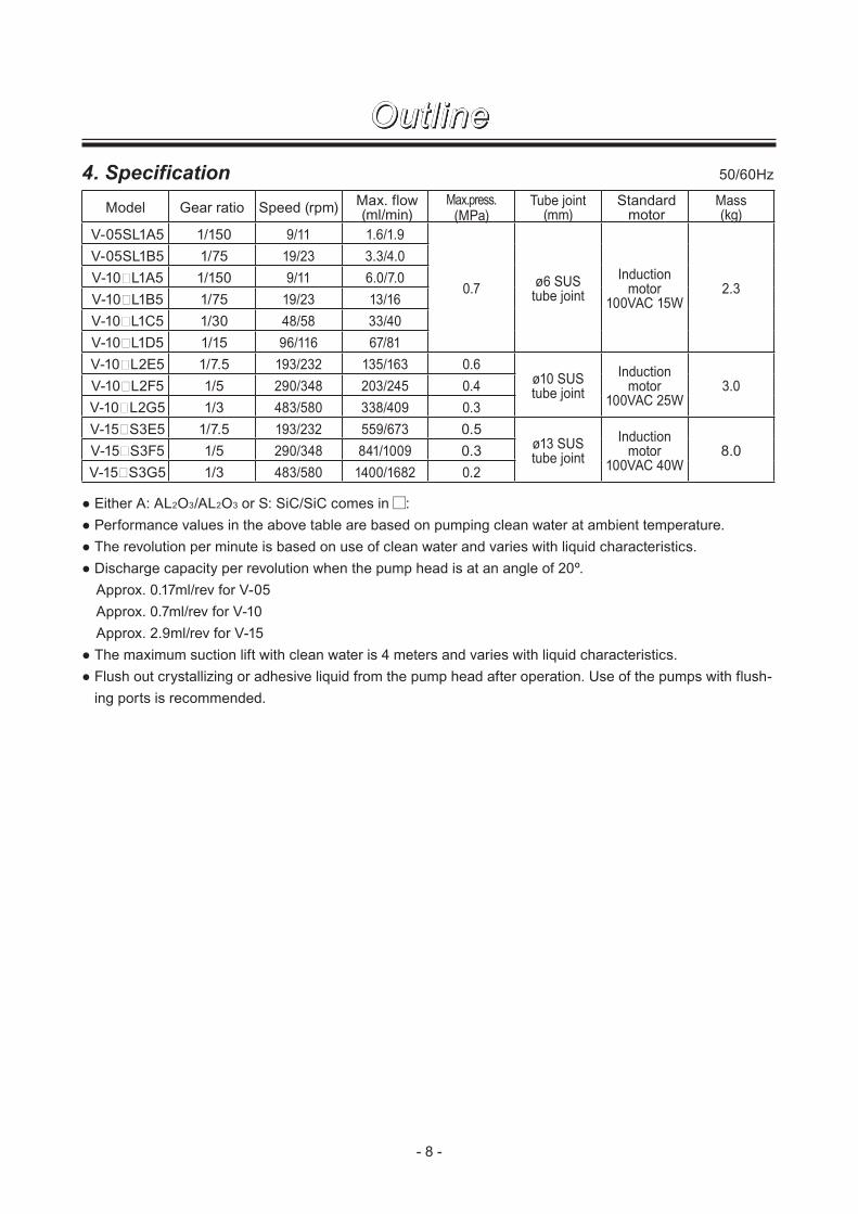
4. Specification 50/60Hz
Outline
Model Gear ratio Speed (rpm)Max. flow(ml/min)
Max.press.(MPa)
Tube joint(mm)
Standard motor
Mass(kg)
V-05SL1A5 1/150 9/11 1.6/1.9
0.7ø6 SUStube joint
Induction motor
100VAC 15W2.3
V-05SL1B5 1/75 19/23 3.3/4.0
V-10�L1A5 1/150 9/11 6.0/7.0
V-10�L1B5 1/75 19/23 13/16
V-10�L1C5 1/30 48/58 33/40
V-10�L1D5 1/15 96/116 67/81
V-10�L2E5 1/7.5 193/232 135/163 0.6ø10 SUStube joint
Induction motor
100VAC 25W3.0V-10�L2F5 1/5 290/348 203/245 0.4
V-10�L2G5 1/3 483/580 338/409 0.3
V-15�S3E5 1/7.5 193/232 559/673 0.5ø13 SUStube joint
Induction motor
100VAC 40W8.0V-15�S3F5 1/5 290/348 841/1009 0.3
V-15�S3G5 1/3 483/580 1400/1682 0.2
● Either A: AL2O3/AL2O3 or S: SiC/SiC comes in :
● Performance values in the above table are based on pumping clean water at ambient temperature.
● The revolution per minute is based on use of clean water and varies with liquid characteristics.
● Discharge capacity per revolution when the pump head is at an angle of 20º.
Approx. 0.17ml/rev for V-05
Approx. 0.7ml/rev for V-10
Approx. 2.9ml/rev for V-15
● The maximum suction lift with clean water is 4 meters and varies with liquid characteristics.
● Flush out crystallizing or adhesive liquid from the pump head after operation. Use of the pumps with flush-
ing ports is recommended.

- 9 -
Installation
1. Before installation ............................... 10
2. Installation/Piping/Wiring .................... 12

- 10 -
1. Before installation1. Do not run pump dry (except for the start-up dry
running to fill the pump head with liquid.)
Friction heat builds up in the pump head during
dry running and the plunger seizes in the cylin-
der.
2. Do not close valves
Closed-discharge operation causes a sharp
pressure rise and may result in pump failure or
motor burning out. Be sure to open a suction line
and a discharge line before operation.
3. Degassing
Fully open a discharge line and set the pump
head angle to 20º (the maximum stroke length).
Run the pump in this condition to expel air from
the pump and tubing.
4. Temperature influence
A flow rate, liquid viscosity, vapour pressure and
corrosion resistance changes with liquid tem-
perature.
CAUTION:
The allowable liquid temperature range is
0-80ºC. Apply heat-resistant grease to the
motor bearing or use a cooling fan to cool
down motor temperature when liquid tem-
perature exceeds 65ºC.
5. Viscous liquid
The pump is capable of handling liquid up to
20,000 cP, but then keep pump rotation speed
lower as viscosity gets higher, especially when
liquid viscosity is 500 cP or more. Contact us for
detail.
Discharge valve
Suction valve
Viscous liquid
Installation

- 11 -
6. Precipitation or Crystallization
Flush out liquid that has property of precipitation
or crystallization from the pump head.
CAUTION
If the pump is left before flushing, the
plunger may be stuck in the cylinder. In this
case the pump does not start to run.
7. Operating conditions
Do not cover the motor tight. Avoid areas where
ambient temperature exceeds 40ºC or ambient
humidity exceeds 85% RH. Do not wet the pump,
or an electrical leak or a fire may result.
8. Earthing
Be sure to earth the pump. Install an earth leak-
age breaker as necessary.
CAUTION
If an earth leakage breaker has worked to
open a circuit, turn off a main power-supply
switch. Always determine a root cause and
solve problems before resuming operation.
9. Take preventative measures for fire and dust
CAUTION
Do not place a dangerous or a flamma-
ble substance near the pump. Protect the
motor from dust.
Earth
Installation

- 12 -
4m
Rubber plate
2. Installation/Piping/Wiring■ Installation
1. Select an installation location where is con-
venient for maintenance. Ambient temperature
should not exceed 40ºC or falls below 0ºC.
Observe the maximum ambient humidity of
85%RH. Do not install the pump out of doors.
CAUTION
When installing the pump, be careful not
to impact the pump. A strong impact may
adversely affect pump performance.
The pump can be mounted either verti-
cally or horizontally. A flow direction can be
reversed by inverting motor rotation.
2. The maximum suction lift is 4 meters based on
operation with clean water and changes accord-
ing to liquid characteristics.
3. Fix the pump with M5 screws. Place a rubber
plate beneath the pump base to reduce noise or
oscillation as necessary.
Installation
- 13 -
Motor
CWCCW
Black
Red
White
Capacitor
CW
CCWSW
Line
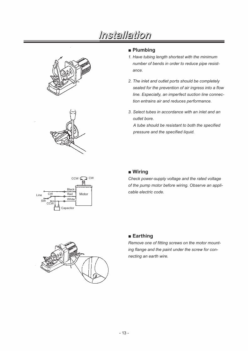
■ Plumbing
1. Have tubing length shortest with the minimum
number of bends in order to reduce pipe resist-
ance.
2. The inlet and outlet ports should be completely
sealed for the prevention of air ingress into a flow
line. Especially, an imperfect suction line connec-
tion entrains air and reduces performance.
3. Select tubes in accordance with an inlet and an
outlet bore.
A tube should be resistant to both the specified
pressure and the specified liquid.
■ Wiring
Check power-supply voltage and the rated voltage
of the pump motor before wiring. Observe an appli-
cable electric code.
■ Earthing
Remove one of fitting screws on the motor mount-
ing flange and the paint under the screw for con-
necting an earth wire.
Installation

- 14 -
Operation
1. Operation ............................................ 15

- 15 -
1. OperationDo not run pump dry or run it with a discharge valve or a suction valve closed.
■ Starting process
Operate the pump according to the following procedure after installation, tubing and wiring of pump.
No. Points to be checked Procedure
1
Tubing, wiring and voltage ● See "■ Plumbing" and "■ Wiring" sections.
● Check the spec label to see if the power supply voltage is
correct.
2 A discharge and a suction line. ● Fully open both suction and discharge valves.
3
Rotational direction ● Check if the direction of rotation is correct.
Prime the pump and run the motor for just a moment to
check a flow direction.
● Counter clockwise (CCW)
CCW rotation seen from the
motor end. Liquid flows in the
direction of "a".
● Clockwise (CW)
CW rotation seen from the
motor end. Liquid flows in the
direction of "b".
4
Starting ● Run the pump for a while and check liquid flows without a
hitch. Upon finding abnormality, turn off power and solve the
cause of abnormality. Refer to "Troubleshooting" section.
5
Operation ● Make sure air has been expelled from the pump and a tub-
ing system completely. If not, an accurate flow rate can not
be obtained. Angle the pump head to 20º and run the pump
until air is expelled completely. After air is all eliminated,
adjust discharge pressure to a specified level.
● Flow rate can be adjusted from 0 to the maximum by chang-
ing the pump head angle.
6
Points to be checked during
operation
● Do not allow foreign matters to enter the pump. Foreign mat-
ters may cause the plunger to be locked or damaged, hin-
dering a liquid circulation.
Install a dampener to reduce pulsation as necessary. Contact for us for detail.
■ Stoppage
No. Points to be checked Procedure
1
Wet ends ● Flush the pump head with clean water after operation with
sticky or settling liquid. Dismantle the pump head for clean-
ing as necessary.
2Before a long period of stoppage ● Drain liquid from the pump head and dismantle it for clean-
ing before a long period of stoppage.
Operation
a
b

- 16 -
Operation
■ Daily inspection
See the following check items in operation. On detection of abnormality, stop operation immediately. Take
measures referring to the item "Trouble shooting".
No. States Points to be checked How to check
1
Pumping • If liquid is pumped. Flow meter or
visual inspection
• If discharge pressure/ suction pressure is normal. Check specifica-
tion.
2
Noise and vibration • If abnormal noise or vibration occurs. They are signs
of abnormal operation.
Visual or audio
inspection
• Place a rubber plate beneath the pump base to reduce
noise or oscillation as necessary.
3
Air ingress from pump
head joints and a suc-
tion line
• If leakage occurs. Visual inspection
• If pumped liquid includes air bubbles, check lines for
leakage and retighten as necessary.
4
High surface tempera-
ture of the pump and the
motor
• Pump surface temperature gets higher along with liq-
uid temperature.
Touch or use a
thermometer
• Motor surface temperature should be 40ºC higher than
ambient temperature, or below.
- 17 -
Maintenance
1. Disassembly & Assembly .................... 18
2. Troubleshooting .................................. 24
3. Dimensions ......................................... 25
4. Wear parts .......................................... 27

- 18 -
1. Disassembly & Assembly
■ Exploded view (V-05/-10)
No. Part names Q'ty Remarks No. Part names Q'ty Remarks
1 Plunger 1 Al2O3/SiC 14 Mounting plate 1
2 Cylinder 1 Al2O3/SiC 15 Drive joint 1 AL
3 Pump head 1 SCS14 16 Spherical bearing 1
4 Cap nut 1 SUS303 17 Cap 1
5 Tube joint 2 SUS316 18 Lock lever 1 Zn
6 Joint seal 2 PTFE 19 Lock bar 1
7 Head seal 1 PTFE 20Hex. sock head
bolt (with sw)1 SUS304
8 Lip seal 3 PTFE 21 Back seat 1 PTFE
9 Bearing case 1 AC4C 50 Induction motor 1
10 Bearing 1 6004ZZ 101 Plunger ass'y 1
11 Stop ring 1 102 Bearing case ass'y 1
12 Joint cover 1 AL 103 Drive joint ass'y 1
13 Base 1
11
10
15
12
1
2
17 16
Maintenance

- 19 -
■ Dismantlement (V-05/-10)
Follow the procedure below to take apart the pump
head.
1. Remove tube connections from the pump head.
Be careful not to get wet with chemical liquid.
Wipe chemicals off immediately when your hand
or component parts get wet.
2. Remove the base (13) from a foundation.
3. Release the lock lever (18) and direct the pump
head to 10º position.
4. Loosen the hex sock head bolt (20) via the hole
beneath the base (13) and unfix the connection
between the pump head (3) and the mounting
plate (14).
5. Take out the pump head (3) from the drive joint
ass'y (103) with the cylinder and plunger (1) in it.
6. Remove the cap nut (4) from the pump head and
pull out the cylinder (2) with the plunger (1) in it.
7. Pull out the plunger (1) by rotating it in the cylin-
der (2).
8. Pull out the lip seals (8) by rotating them slowly
on the plunger.
Be careful not to damage lip seals. Clean all parts
thoroughly after dismantlement.
Maintenance

- 20 -
■ Assembly (V-05/-10)
Follow the procedure below to put together the
pump head.
1. Insert the head seal (7) first and then the cylinder
(2) into the pump head (3).
Make sure the flow paths of the cylinder lie direc-
tory beneath those of the pump head. The head
seal of the V-05 has mounting direction. Always
direct its concave side to the cylinder (2).
2. Fit the joint seals (6) into the tube joints (5) and
then screw these joints into the pump head (3) to
softly hold the cylinder.
3. First slide the cap nut (4), then the back seat and
the lip seals (8) onto the plunger (1) as far as they
will go. Softly rotate the lip seals on the plunger
when sliding them onto it. See the enlarged
photo on the left for the mounting direction of the
lip seals.
Do not bend or scratch the lip seals. Degrease
and clean the plunger with benzine or thinner
after this process.
4. Hold the plunger pin and pass the plunger (1)
through the cylinder (2), rotating it from side to
side.
5. Tighten the cap nut (4) to the pump head by a
torque in between 20 and 30kgf•cm.
6. Tighten the tube joints to the pump head by
15kgf•cm.
Do not tighten the tube joints too much, or they
deform the cylinder and prevent the rotation of
the plunger.
7. Pull out the plunger end from the pump head and
fit the plunger pin into the spherical bearing in the
drive joint ass'y (103).
Adjust the direction of the spherical bearing as
necessary. Always grease the plunger pin to keep
good lubrication performance.
8. Place the pump head onto the mounting plate
(14) and direct the pump head to 10º position.
Fix the connection between the pump head (3)
and the mounting plate (14) with a spring washer
and the hex socket head bolt (20) via the hole
beneath the base (13).
Plunger
Back seat
Lip seals
Plunger pin
Cap nut
Maintenance

- 21 -
1
2
23
■ Exploded view (V-15)
No. Part names Q'ty Remarks No Part names Q'ty Remarks
1 Plunger ass'y 1 Al2O3/SiC 14 Drive joint ass'y 1
2 Cylinder 1 Al2O3/SiC 15 Bearing case ass'y 1
3 Pump head 1 SUS304 16 Drive joint cover 1 SUS304
4 Head cover 1 SUS304 18 Pump base 1 SPCC
5 Head seal 1 PTFE 19 Angle scale 1 PE
6 Tube joint 2 SUS316 20 Nut (with pw/sw) 1 SUS304
7 Joint seal 2 PTFE 21 Hex. sock head bolt (with sw)
4 SUS304
10 Seal stopper 1 PTFE 22 Hex. sock head bolt (with sw)
1 SUS304
11 Lip seal 2 PTFE 23Pump frame mounting
screw1 SUS304
12 Pump frame 1 SPCC 24 Pumphead mounting screw (with pw/sw)
8 SUS304
13 Motor frame 1 SPCC
Maintenance

- 22 -
■ Dismantlement (V-15)
Follow the procedure below to take apart the pump head.
1. Remove all tube connections from the pump head.
Be careful not to get wet with chemical liquid. Wipe chemicals off immediately when your hand or compo-
nent parts get wet.
2. Remove the pump base (18) from a foundation.
3. Unscrew the pump frame mounting screw (23) and the hex socket head bolt (22) to separate the pump
frame (12) from the motor frame (13).
4. Unhook the plunger ass'y (1) from the drive joint ass'y (14).
5. Pull out the plunger ass'y (1) by rotating it in the cylinder (2).
Do not roughly withdraw the ass'y, or lip seals may be damaged.
6. Remove four pumphead mounting screws (24) on the pump frame (12) to separate the pump head (3).
7. Unscrew and take away all the tube joints (6) from the pump head (3).
8. Unscrew and remove all the four head cover mounting screws to detach the head cover (4) from the pump
head (3).
9. Withdraw the cylinder (2) from the pump head (3).
Clean all parts thoroughly after dismantlement.
10. Pull out the lip seals (11) and seal stopper (10) by rotating them slowly on the plunger.
Do not bend or scratch the lip seals. Clean all parts thoroughly after dismantlement.
Maintenance

- 23 -
■ Assembly (V-15)
Follow the procedure below to put together the pump head.
1. Insert the plunger ass'y (1) into the pump frame (12 ). And then slide the seal stopper (10) down onto the
plunger ass'y as far as it will go.
2. Slide two lip seals (11) down onto the plunger ass'y as far as they will go, rotating each of them slowly, to
align them back to back.
Do not bend or scratch the lip seals. Degrease and clean the plunger with benzine or thinner after this
process.
3. Hold the plunger pin and pass the plunger (1) through the cylinder (2), rotating it from side to side. And
then fit the cylinder into the pump head (3), making sure the cylinder flow paths lie directory beneath those
of the pump head.
4. Fix the pump head with the pump frame (12) with the pumphead mounting screws.
5. Fit the joint seals (7) into the tube joints (6) and then screw these joints into the pump head (3) to softly
hold the cylinder.
6. Place the head seal (5) on the top of the cylinder, on its concave side, and fasten the head cover (4) to the
pump head (3) by 15kgf•cm.
Do not tighten the head cover too much, or it deforms the cylinder and prevent the rotation of the plunger.
7. Tighten the tube joints (6) to the pump head by 15kgf•cm.
Do not tighten the tube joints too much, or it deforms the cylinder and prevent the rotation of the plunger.
8. Pull out the plunger end from the pump head and fit the plunger pin into the spherical bearing in the drive
joint ass'y (14).
Adjust the direction of the spherical bearing as necessary. Always grease the plunger pin to keep good
lubrication performance, or seizing or noise may result.
9. Place the pump head onto the pump base (18). Fix the pump frame (12) with the pump frame mounting
frame (23) plus the nut (20 ) and the hex socket head bolt (22). Do not fasten the bolt too much before
adjusting the pump head angle to a specified point. The range of the pump head angle is in between 0
and 20º.
Maintenance

- 24 -
Maintenance
2. Troubleshooting
Problem Cause Countermeasures
The pump does not start
to run.
Power is not supplied. Supply power.
Wrong wiring or disconnection Correct wiring.
Motor failure (winding disconnection or
capacitor failure)
Replace motor.
*Plunger seizing due to crystallization Take apart the pump head and clean
wet ends.
High specific gravity or high viscosity Use an applicable pump model.
The pump does not de-
liver liquid during opera-
tion.
Dry running Replace both the plunger and cylinder.
A suction and a discharge line is
closed during operation.
Open both the suction and discharge
lines.
A supply tank is empty. Replenish the supply tank.
The motor is rotating the other way
around.
Correct wiring.
A flow rate is too small.
Air ingress through a tube joint. Keep tube joints air-tight.
Pump rotation speed is too low. Increase a rotation speed.
A lip seal is crushed. Replace as necessary.
A suction line is crushed. Replace as necessary.
Significant vibration
or noise
Motor failure (winding disconnection or
capacitor failure)
Replace motor.
Dry running Replace both the plunger and cylinder.
Discharge pressure is too high. Reduce discharge pressure.
A suction and a discharge line is
closed during operation.
Open both the suction and discharge
lines.
Air ingress through a tube joint. Keep tube joints air-tight.
Development of cavitation Reduce a motor rpm, liquid tempera-
ture, and tubing resistance.
*A supply tank is empty. Replenish the supply tank.
*Anchor bolts are loose. Fasten anchor bolts.
Sympathetic vibration with the pump
and other parts of system
Place an anti-vibration rubber beneath
the pump.
Liquid leaks. A lip seal is crushed. Replace as necessary.
Pump stops.
Wrong wiring or disconnection Correct wiring.
Motor failure (winding disconnection or
capacitor failure)
Replace motor.
Clogging due to foreign matters Remove foreign matters. Replace parts
if damaged.
* means major failure cases.

- 25 -
Maintenance
3. Dimensions
V-05/-10 (15W induction motor)
V-05/-10 (25W induction motor)
238 or 248 NOTE2
112 or 122 NOTE1
248 or 259 NOTE4
122 or 133 NOTE3

- 26 -
Maintenance
339 or 357 NOTE54 × ø5
V-15
NOTE1: 112mm for the gear ratio of 1/3-1/15
122mm for the gear ratio of 1/30-1/150
NOTE2: 238mm for the gear ratio of 1/3-1/15
248mm for the gear ratio of 1/30-1/150
NOTE3: 122mm for the gear ratio of 1/3-1/15
133mm for the gear ratio of 1/30-1/150
NOTE4: 248mm for the gear ratio of 1/3-1/15
259mm for the gear ratio of 1/30-1/150
NOTE5: 339mm for the gear ratio of 1/3-1/15
357mm for the gear ratio of 1/30-1/150

- 27 -
Maintenance
4. Wear partsReplace wear parts according to the estimated service life as shown below.
V-05
Parts
Lip seal Joint seal Head seal Back seat
Life 2000hr Each maintenance Each maintenance Each maintenance
Q'ty 3 2 1 1
V-10
Parts
Lip seal Joint seal Head seal Back seat
Life 2000hr Each maintenance Each maintenance Each maintenance
Q'ty 3 2 1 1
V-15
Parts
Lip seal Joint seal Head seal Seal stopper
Life 2000hr Each maintenance Each maintenance When deteriorated
Q'ty 2 2 1 1
Estimated service lives are calculated based on pumping clean water at ambient temperature and 0.3MPa,
and change with liquid pressure, liquid temperature and liquid characteristics.

- 28 -

- 29 -

T607-1 '10/08
( )Country codes
IWAKI CO.,LTD. 6-6 Kanda-Sudacho 2-chome Chiyoda-ku Tokyo 101-8558 Japan
TEL:(81)3 3254 2935 FAX:3 3252 8892(http://www.iwakipumps.jp)
Australia IWAKI Pumps Australia Pty. Ltd. TEL : (61)2 9899 2411 FAX : 2 9899 2421 Italy IWAKI Italia S.R.L. TEL : (39)02 990 3931 FAX : 02 990 42888
Austria IWAKI (Austria) GmbH TEL : (43)2236 33469 FAX : 2236 33469 Korea IWAKI Korea Co.,Ltd. TEL : (82)2 2630 4800 FAX : 2 2630 4801
Belgium IWAKI Belgium n.v. TEL : (32)1367 0200 FAX : 1367 2030 Malaysia IWAKIm Sdn. Bhd. TEL : (60)3 7803 8807 FAX : 3 7803 4800
China IWAKI Pumps (Shanghai) Co., Ltd. TEL : (86)21 6272 7502 FAX : 21 6272 6929 Norway IWAKI Norge AS TEL : (47)66 81 16 60 FAX : 66 81 16 61
China IWAKI Pumps (Guandong) Co., Ltd. TEL : (86)750 3866228 FAX : 750 3866278 Singapore IWAKI Singapore Pte. Ltd. TEL : (65)6316 2028 FAX : 6316 3221
China GFTZ IWAKI Engineering & Trading (Guangzhou) TEL : (86)20 8435 0603 FAX : 20 8435 9181 Spain IWAKI Iberica Pumps, S.A. TEL : (34)943 630030 FAX : 943 628799
China GFTZ IWAKI Engineering & Trading (Beijing) TEL : (86)10 6442 7713 FAX : 10 6442 7712 Sweden IWAKI Sverige AB TEL : (46)8 511 72900 FAX : 8 511 72922
Denmark IWAKI Nordic A/S TEL : (45)48 24 2345 FAX : 48 24 2346 Switzerland IWAKI (Schweiz) AG TEL : (41)26 674 9300 FAX : 26 674 9302
Finland IWAKI Suomi Oy TEL : (358)9 2745810 FAX : 9 2742715 Taiwan IWAKI Pumps Taiwan Co., Ltd. TEL : (886)2 8227 6900 FAX : 2 8227 6818
France IWAKI France S.A. TEL : (33)1 69 63 33 70 FAX : 1 64 49 92 73 Taiwan IWAKI Pumps Taiwan (Hsin-chu) Co., Ltd. TEL : (886)3 573 5797 FAX : (886)3 573 5798
Germany IWAKI EUROPE GmbH TEL : (49)2154 9254 0 FAX : 2154 9254 48 Thailand IWAKI (Thailand) Co.,Ltd. TEL : (66)2 322 2471 FAX : 2 322 2477
Holland IWAKI EUROPE NL Branch TEL : (31)547 293 160 FAX : 547 292 332 U.K. IWAKI Pumps (UK) LTD. TEL : (44)1743 231363 FAX : 1743 366507
Hong Kong IWAKI Pumps Co., Ltd. TEL : (852)2 607 1168 FAX : 2 607 1000 U.S.A. IWAKI AMERICA Inc. TEL : (1)508 429 1440 FAX : 508 429 1386
Indonesia IWAKI Singapore (Indonesia Branch) TEL : (62)21 690 6606 FAX : 21 690 6612 Vietnam IWAKI pumps Vietnam Co.,Ltd. TEL : (84)613 933456 FAX : 613 933399