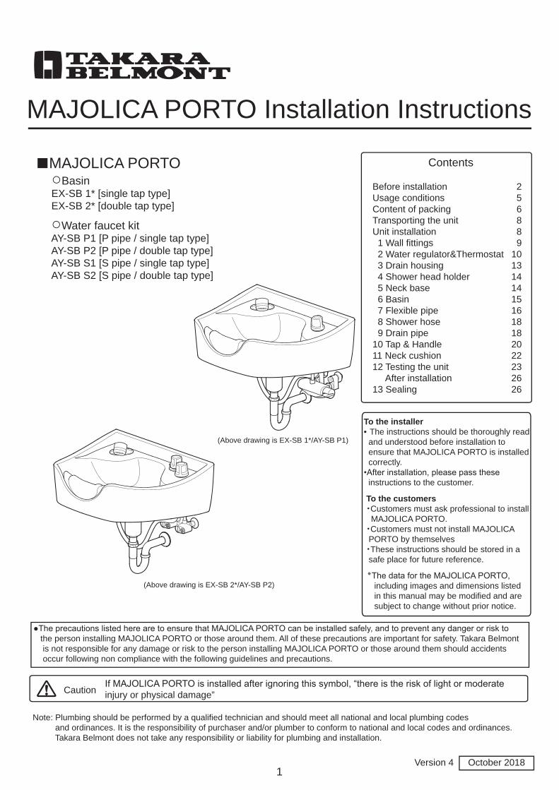
MAJOLICA PORTO Installation Instructions
■MAJOLICA PORTOBefore installationUsage conditionsContent of packingTransporting the unitUnit installation 1 Wall fittings 2 Water regulator&Thermostat 3 Drain housing 4 Shower head holder 5 Neck base 6 Basin 7 Flexible pipe 8 Shower hose 9 Drain pipe10 Tap & Handle11 Neck cushion12 Testing the unit After installation13 Sealing
Contents
2 5 6 8 8 910131414151618182022232626
○BasinEX-SB 1* [single tap type]EX-SB 2* [double tap type]
○Water faucet kitAY-SB P1 [P pipe / single tap type]AY-SB P2 [P pipe / double tap type]AY-SB S1 [S pipe / single tap type]AY-SB S2 [S pipe / double tap type]
(Above drawing is EX-SB 1*/AY-SB P1)
(Above drawing is EX-SB 2*/AY-SB P2)
●The precautions listed here are to ensure that MAJOLICA PORTO can be installed safely, and to prevent any danger or risk to the person installing MAJOLICA PORTO or those around them. All of these precautions are important for safety. Takara Belmont is not responsible for any damage or risk to the person installing MAJOLICA PORTO or those around them should accidents occur following non compliance with the following guidelines and precautions.
Note: Plumbing should be performed by a qualified technician and should meet all national and local plumbing codes and ordinances. It is the responsibility of purchaser and/or plumber to conform to national and local codes and ordinances. Takara Belmont does not take any responsibility or liability for plumbing and installation.
1
To the installer• The instructions should be thoroughly read and understood before installation to ensure that MAJOLICA PORTO is installed correctly.•After installation, please pass these instructions to the customer.
To the customers・Customers must ask professional to install MAJOLICA PORTO.・Customers must not install MAJOLICA PORTO by themselves・These instructions should be stored in a safe place for future reference.
,The data for the MAJOLICA PORTO٭ including images and dimensions listed in this manual may be modified and are subject to change without prior notice.
CautionIf MAJOLICA PORTO is installed after ignoring this symbol, “there is the risk of light or moderateinjury or physical damage”
Version 4 October 2018
2
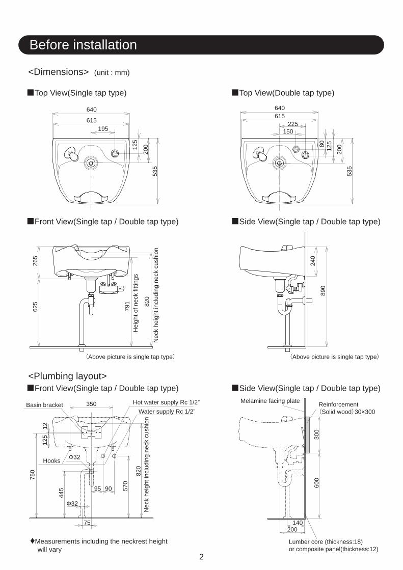
Before installation
<Dimensions> (unit : mm)
<Plumbing layout>
Top View(Single tap type) Top View(Double tap type)
Front View(Single tap / Double tap type) Side View(Single tap / Double tap type)
Front View(Single tap / Double tap type) Side View(Single tap / Double tap type)
Measurements including the neckrest height will vary
Lumber core (thickness:18)or composite panel(thickness:12)
Reinforcement(Solid wood)30×300
Melamine facing plate
640
615
640
225615
19512
5
200
535
265
240
890
300
600
625
535
12580
200
150
140200
75
95 90
350Basin bracket
Hooks
Hot water supply Rc 1/2”Water supply Rc 1/2”
820
570
445
125
750
12
Nec
k he
ight
incl
udin
g ne
ck c
ushi
on
791 82
0N
eck
heig
ht in
clud
ing
neck
cus
hion
Hei
ght o
f nec
k fit
tings
(Above picture is single tap type) (Above picture is single tap type)
3
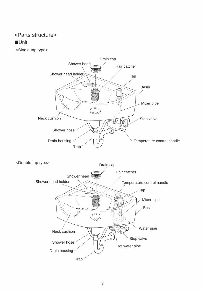
<Parts structure> Unit
<Single tap type>
Drain cap
Hair catcher
Tap
Basin
Mixer pipe
Stop valve
Temperature control handle
Shower head
Shower head holder
Neck cushion
Shower hose
Drain housingTrap
Drain cap
Hair catcher
Temperature control handle
Tap
Mixer pipe
Basin
Water pipe
Stop valve
Hot water pipe
Neck cushion
Shower head holderShower head
Shower hose
Drain housing
Trap
<Double tap type>
4
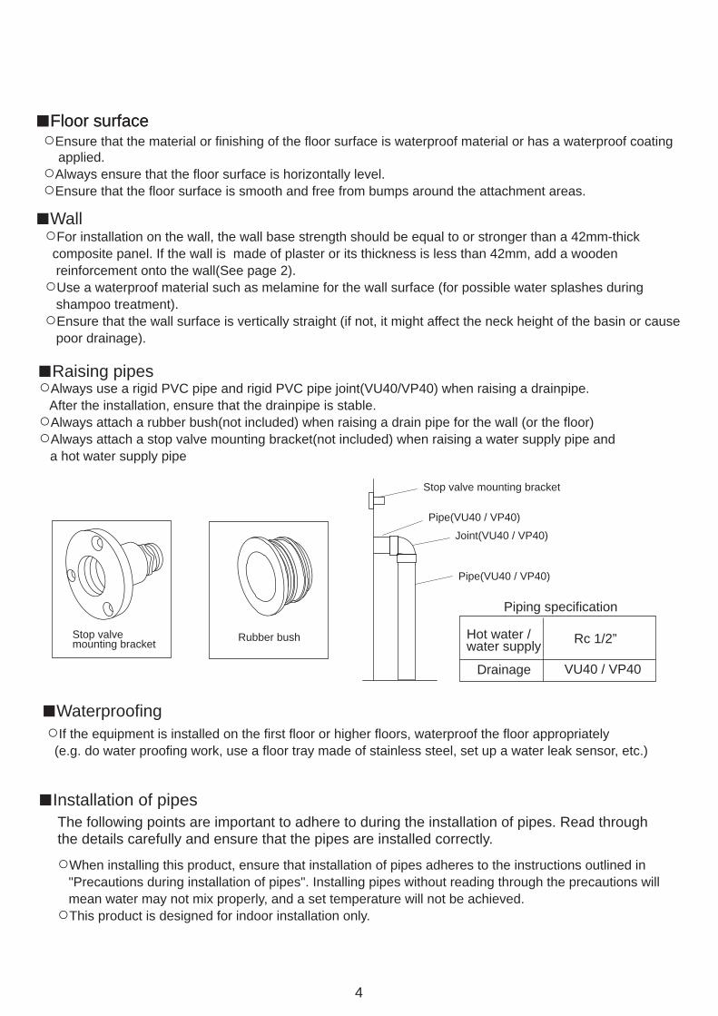
Floor surfaceFloor surface
Wall
Ensure that the material or finishing of the floor surface is waterproof material or has a waterproof coating applied.
Always ensure that the floor surface is horizontally level. Ensure that the floor surface is smooth and free from bumps around the attachment areas.
For installation on the wall, the wall base strength should be equal to or stronger than a 42mm-thick composite panel. If the wall is made of plaster or its thickness is less than 42mm, add a wooden reinforcement onto the wall(See page 2).
Use a waterproof material such as melamine for the wall surface (for possible water splashes during shampoo treatment).
Ensure that the wall surface is vertically straight (if not, it might affect the neck height of the basin or cause poor drainage).
Raising pipesAlways use a rigid PVC pipe and rigid PVC pipe joint(VU40/VP40) when raising a drainpipe.
After the installation, ensure that the drainpipe is stable.Always attach a rubber bush(not included) when raising a drain pipe for the wall (or the floor)Always attach a stop valve mounting bracket(not included) when raising a water supply pipe and
a hot water supply pipe
WaterproofingIf the equipment is installed on the first floor or higher floors, waterproof the floor appropriately
(e.g. do water proofing work, use a floor tray made of stainless steel, set up a water leak sensor, etc.)
Installation of pipesThe following points are important to adhere to during the installation of pipes. Read through the details carefully and ensure that the pipes are installed correctly.
When installing this product, ensure that installation of pipes adheres to the instructions outlined in "Precautions during installation of pipes". Installing pipes without reading through the precautions will mean water may not mix properly, and a set temperature will not be achieved.
This product is designed for indoor installation only.
Stop valvemounting bracket Rubber bush
Stop valve mounting bracket
Pipe(VU40 / VP40)
Joint(VU40 / VP40)
Pipe(VU40 / VP40)
Piping specification
Hot water / water supply Rc 1/2”
VU40 / VP40Drainage
Usage conditions
5
Precautions during installation of pipesDo not use pipes made of materials that may cause rust in the water supply pipe. In general, VP pipes
or other materials specified by regulations for a particular region, are recommended for installation. In general, Type L deoxidized copper pipes are recommended for hot water pipes. In general, the same diameter and same pressure is recommended for hot water pipes and
water supply pipes. Always use a reamer to deburr the ends of cut pipes.Avoid using inverted U-shaped pipes (siphon) as these can cause air to become trapped. Always connect hot water pipes and water supply pipes after removing all contaminants such as dirt,
sand and oil as these can cause problems. After connecting the pipes and testing water flow, clean the filter and shower head. Ensure that the drain pipe is installed at a gradient of 1/50 for a diameter of 75mm or less,
or 1/100 for a diameter of 75mm or more. Do not connect the hot water pipes and water supply pipes in reverse. Connecting pipes in reverse will
mean the temperature of water cannot be controlled properly by the water taps, which may cause scalds or burns.
Ensure that the hot water pipes from water boilers are only run over a short distance so as to minimize resistance. Longer pipes can cause fluctuations in temperature and poor hot water delivery.
Always wrap pipes with lagging material after installation is complete. Water boiler pipes
water pipes and main water supply pipes.
The equipment comes with a strainer installed.
Hot water supply and water supply conditions
Water used
Hot water supply,water supply pressure
Hot water temperatureinto the product
℃ or less.℃ or higher than the shower temperature used.
rust or sand.)
buildup of scale within the basin body. Aeration may be minimal when using
installed.
~ 2
2
2
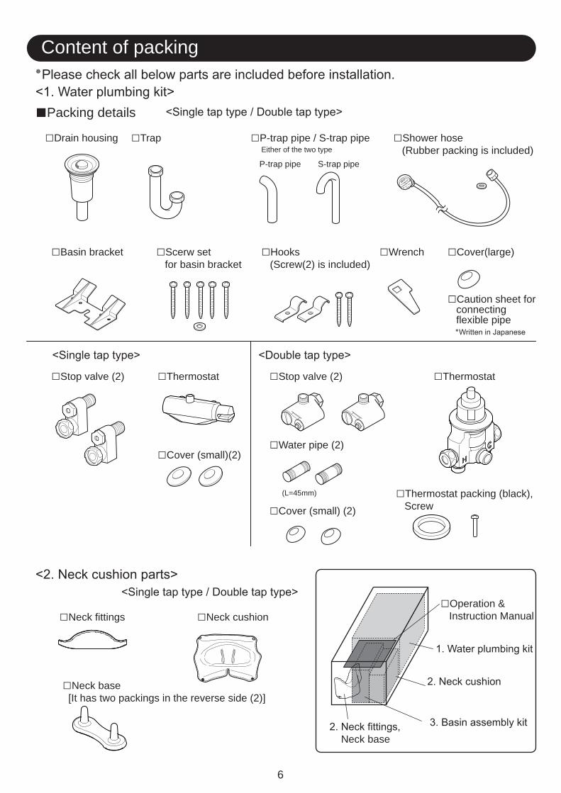
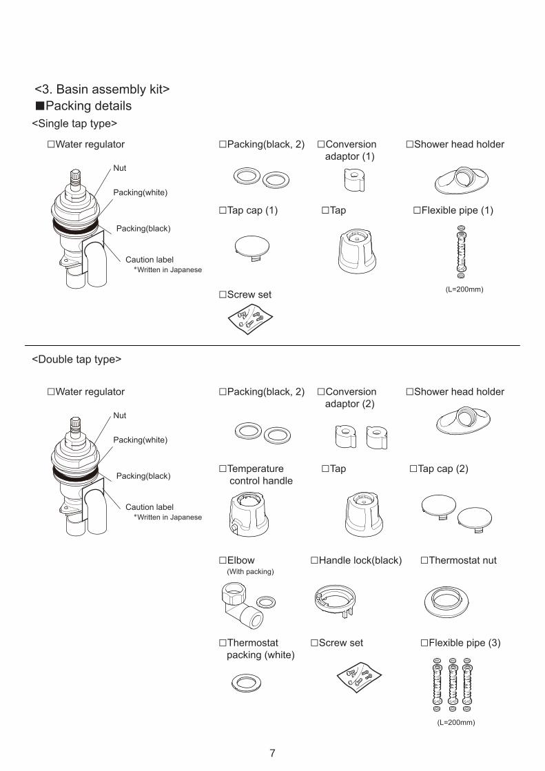
Content of packing
6
Drain housing Trap P-trap pipe / S-trap pipe Shower hose (Rubber packing is included)Either of the two type
P-trap pipe S-trap pipe
Basin bracket
Stop valve (2)
Scerw set for basin bracket
Hooks (Screw(2) is included)
Wrench Cover(large)
Caution sheet for connecting flexible pipe
Thermostat ThermostatStop valve (2)
Water pipe (2)
(L=45mm)
Cover (small) (2)
Cover (small)(2)
Neck fittings Neck cushion
Neck base [It has two packings in the reverse side (2)]
Packing details
Thermostat packing (black), Screw
Operation & Instruction Manual
Neck base
7
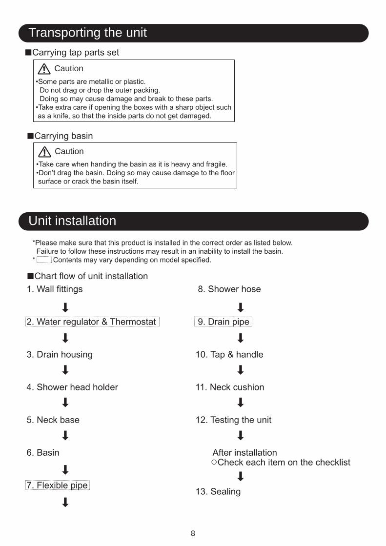
Transporting the unit
Unit installation
8
Caution
Caution
9
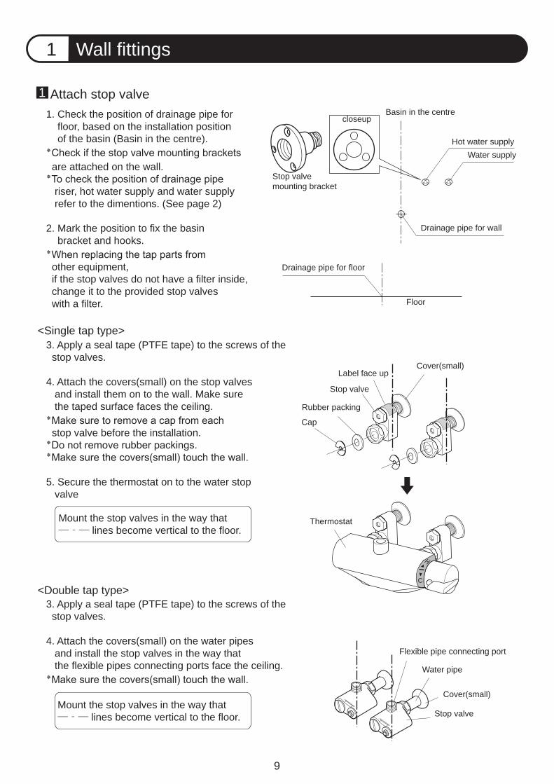
Wall fittings1
Basin in the centrecloseup
Stop valvemounting bracket
Hot water supplyWater supply
Drainage pipe for wall
Floor
Drainage pipe for floor
Cover(small)Label face up
Stop valve
Rubber packing
Cap
Thermostat
Flexible pipe connecting port
Water pipe
Cover(small)
Stop valve
H
C
Attach stop valve1. Check the position of drainage pipe for floor, based on the installation position of the basin (Basin in the centre).
are attached on the wall.
riser, hot water supply and water supply refer to the dimentions. (See page 2)
2. Mark the position to fix the basin bracket and hooks.
other equipment, if the stop valves do not have a filter inside, change it to the provided stop valves with a filter.
3. Apply a seal tape (PTFE tape) to the screws of the stop valves.
4. Attach the covers(small) on the stop valves and install them on to the wall. Make sure the taped surface faces the ceiling.
stop valve before the installation.
5. Secure the thermostat on to the water stop valve
Mount the stop valves in the way that ―‐― lines become vertical to the floor.
3. Apply a seal tape (PTFE tape) to the screws of the stop valves.
4. Attach the covers(small) on the water pipes and install the stop valves in the way that the flexible pipes connecting ports face the ceiling.
1
<Single tap type>
<Double tap type>
Mount the stop valves in the way that―‐― lines become vertical to the floor.
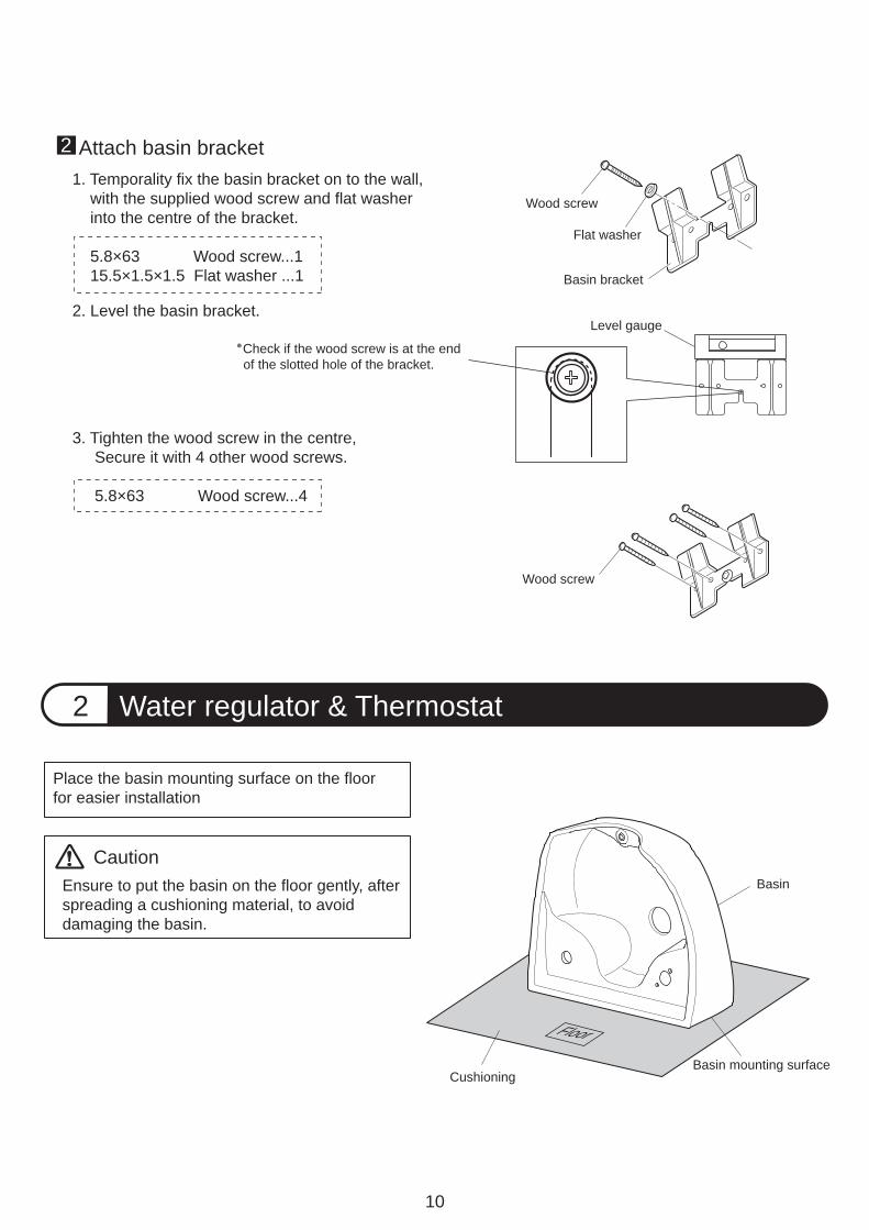
Place the basin mounting surface on the floor for easier installation
10
Water regulator & Thermostat2
Wood screw
Attach basin bracket1. Temporality fix the basin bracket on to the wall, with the supplied wood screw and flat washer into the centre of the bracket.
5.8×63 Wood screw...1 15.5×1.5×1.5 Flat washer ...1
2. Level the basin bracket.
2
Ensure to put the basin on the floor gently, afterspreading a cushioning material, to avoid damaging the basin.
Caution
CushioningBasin mounting surface
Basin
3. Tighten the wood screw in the centre, Secure it with 4 other wood screws. 5.8×63 Wood screw...4
Check if the wood screw is at the end of the slotted hole of the bracket.
Level gauge
Flat washer
Basin bracket
Wood screw
Floor
11
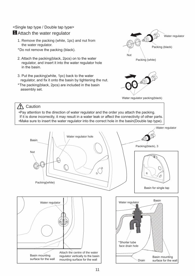
■Attach the water regulator1. Remove the packing (white, 1pc) and nut from the water regulator..Do not remove the packing (black)٭
2. Attach the packing(black, 2pcs) on to the water regulator, and insert it into the water regulator hole in the basin.
3. Put the packing(white, 1pc) back to the water regulator, and fix it onto the basin by tightening the nut. The packing(black, 2pcs) are included in the basin٭ assembly set.
1
Basin mountingsurface for the wall
Attach the centre of the waterregulator vertically to the basinmounting surface for the wall Drain
Basin mountingsurface for the wall
Water regulator Basin
Shorter tube٭ face drain hole
Basin for single tap
Packing(white)
Nut
BasinWater regulator hole
Packing(black), 3
Water regulator
Water regulator
Water regulator packing(black)
Packing (black)
Packing (white)Nut
Caution•Pay attention to the direction of water regulator and the order you attach the packing. If it is done incorrectly, it may result in a water leak or affect the connectivity of other parts.•Make sure to insert the water regulator into the correct hole in the basin(Double tap type).
<Single tap type / Double tap type>
Water regulator
12
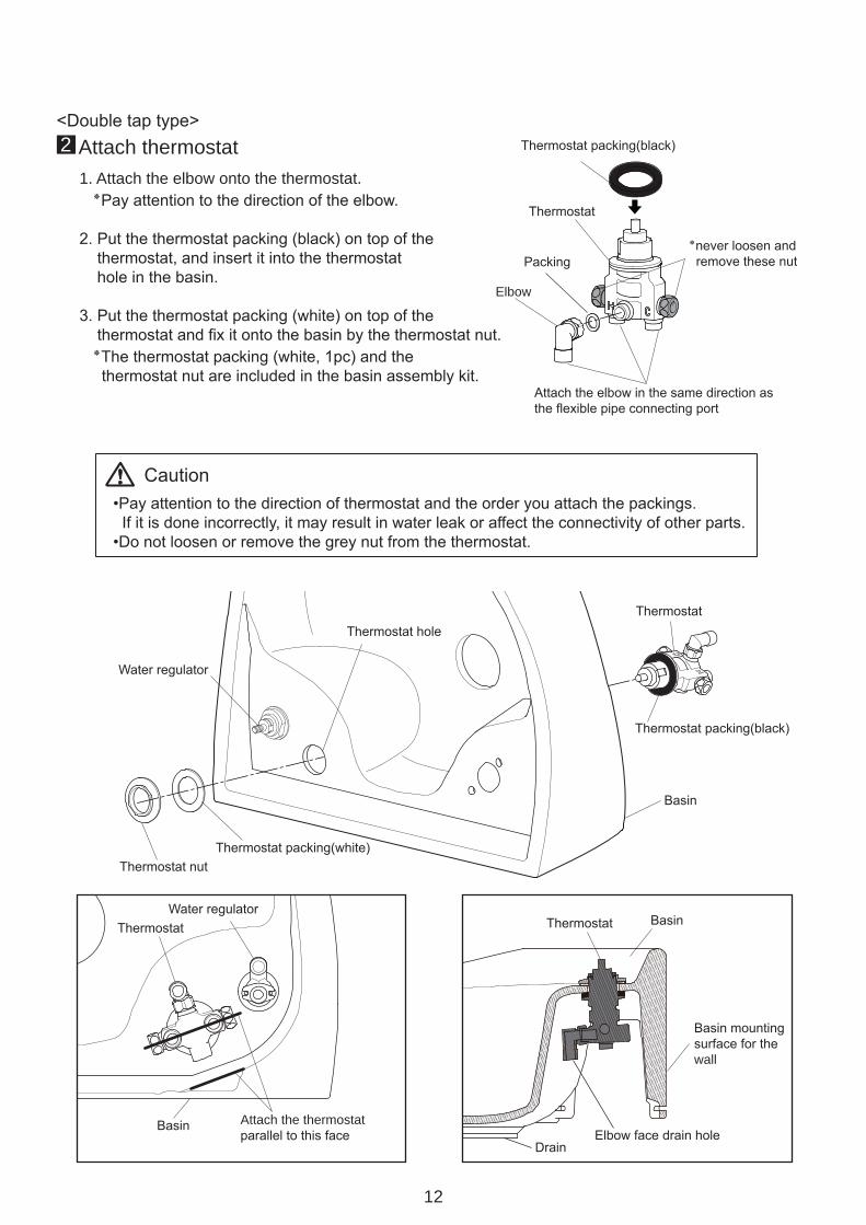
■Attach thermostat1. Attach the elbow onto the thermostat..Pay attention to the direction of the elbow٭
2. Put the thermostat packing (black) on top of the thermostat, and insert it into the thermostat hole in the basin.
3. Put the thermostat packing (white) on top of the thermostat and fix it onto the basin by the thermostat nut. The thermostat packing (white, 1pc) and the٭ thermostat nut are included in the basin assembly kit.
2
Basin mountingsurface for the wall
Thermostat packing(black)
<Double tap type>
•Pay attention to the direction of thermostat and the order you attach the packings. If it is done incorrectly, it may result in water leak or affect the connectivity of other parts.•Do not loosen or remove the grey nut from the thermostat.
Caution
Thermostat
Packing
Elbow
never loosen and٭ remove these nut
Attach the elbow in the same direction asthe flexible pipe connecting port
Thermostat
Thermostat packing(black)
Basin
Thermostat nutThermostat packing(white)
Water regulator
Thermostat hole
Water regulatorThermostat
Basin Attach the thermostatparallel to this face
DrainElbow face drain hole
Thermostat Basin
Basin mountingsurface for thewall
13
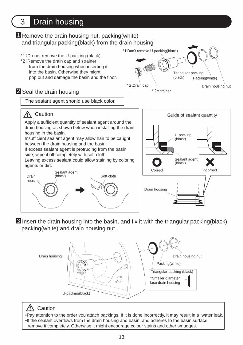
Drain housing3■Remove the drain housing nut, packing(white) and triangular packing(black) from the drain housing
.Do not remove the U-packing (black):1٭Remove the drain cap and strainer:2٭ from the drain housing when inserting it into the basin. Otherwise they might pop out and damage the basin and the floor.
1
■Seal the drain housing2
■Insert the drain housing into the basin, and fix it with the triangular packing(black), packing(white) and drain housing nut.3
Drain cap:2٭Strainer:2٭
Don’t remove U-packing(black):1٭
Triangular packing(black) Packing(white)
Drain housing nut
Sealant agent(black)
CautionApply a sufficient quantity of sealant agent around the drain housing as shown below when installing the drain housing in the basin. Insufficient sealant agent may allow hair to be caught between the drain housing and the basin.If excess sealant agent is protruding from the basin side, wipe it off completely with soft cloth. Leaving excess sealant could allow staining by coloring agents or dirt.
•Pay attention to the order you attach packings. If it is done incorrectly, it may result in a water leak.•If the sealant overflows from the drain housing and basin, and adheres to the basin surface, remove it completely. Otherwise it might encourage colour stains and other smudges.
Caution
Drain housing
Packing(white)
Drain housing nut
Smaller diameter٭face drain housing
Triangular packing (black)
U-packing(black)
Correct incorrect
Guide of sealant quantity
U-packing(black)
Drain housing
Soft clothSealant agent(black)Drain
housing
The sealant agent shonld use black color.
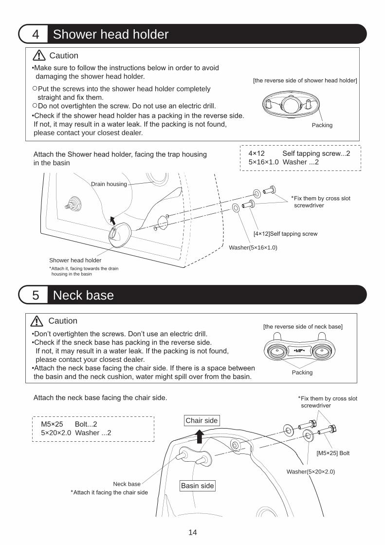
Neck base5
14
Shower head holder4
Caution
damaging the shower head holder.
Put the screws into the shower head holder completely
please contact your closest dealer.
Caution
Packing
Drain housing
housing in the basin
Shower head holder
Washer(5×16×1.0)
5×16×1.0 Washer ...2
5×20×2.0 Washer ...2
Washer(5×20×2.0)
Chair side
Neck base
please contact your closest dealer.
Packing
in the basin
15
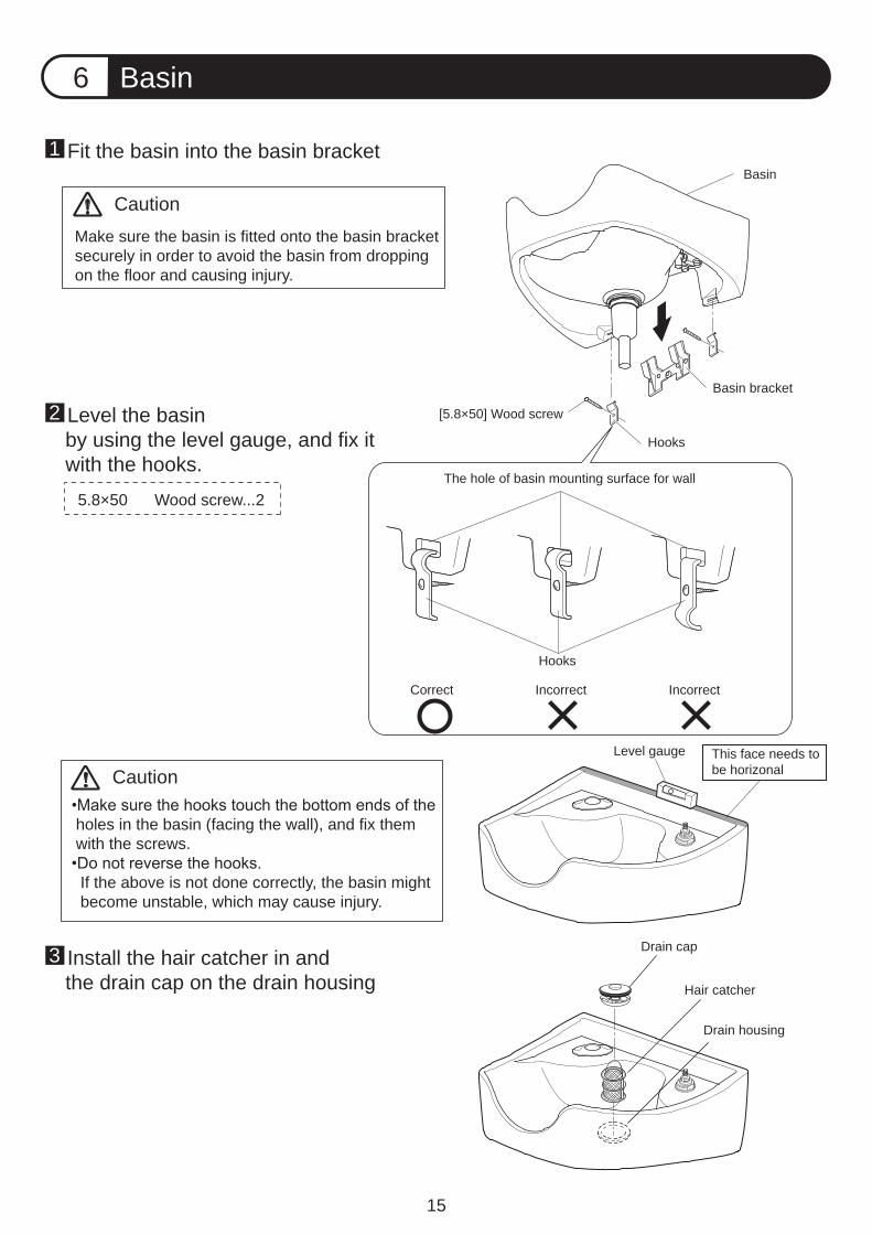
Basin6
Caution
Basin bracket
[5.8×50] Wood screw
Fit the basin into the basin bracket1
Install the hair catcher in and the drain cap on the drain housing3
Level the basin by using the level gauge, and fix it with the hooks.
2
Make sure the basin is fitted onto the basin bracket securely in order to avoid the basin from dropping on the floor and causing injury.
Basin
Hooks
The hole of basin mounting surface for wall
Correct
Hooks
IncorrectIncorrect
Level gauge This face needs tobe horizonal
Drain cap
Hair catcher
Drain housing
5.8×50 Wood screw...2
Caution
holes in the basin (facing the wall), and fix them with the screws.
If the above is not done correctly, the basin might become unstable, which may cause injury.
16
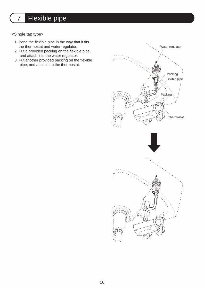
Flexible pipe7
Water regulator
<Single tap type>
PackingFlexible pipe
Packing
Thermostat
1. Bend the flexible pipe in the way that it fits the thermostat and water regulator.2. Put a provided packing on the flexible pipe, and attach it to the water regulator.3. Put another provided packing on the flexible pipe, and attach it to the thermostat.
17
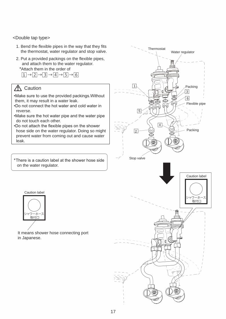
Water regulator
<Double tap type>
Packing
Flexible pipe
Packing
Thermostat1. Bend the flexible pipes in the way that they fits the thermostat, water regulator and stop valve.
2. Put a provided packings on the flexible pipes, and attach them to the water regulator.
Stop valve
Caution label
シャワーホース 取付口
1
2
5
3
6
1 → 2 → 3 → 4 → 5 → 6*Attach them in the order of
Caution
them, it may result in a water leak.
reverse.
do not touch each other.
hose side on the water regulator. Doing so might prevent water from coming out and cause water leak.
on the water regulator.
It means shower hose connecting portin Japanese.
Caution label
シャワーホース 取付口
4
18
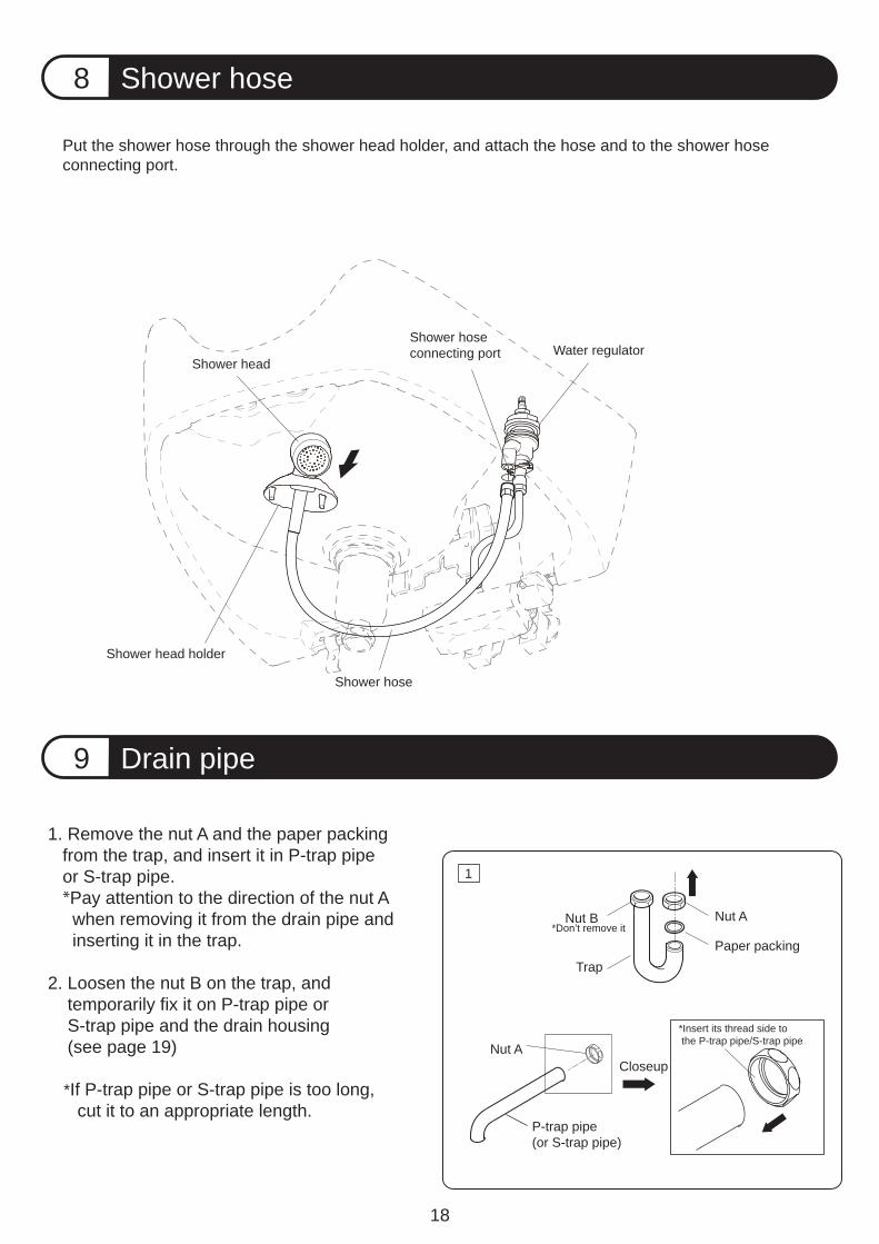
Shower hose8
Drain pipe9
Shower head
Shower hose
Shower head holder
Put the shower hose through the shower head holder, and attach the hose and to the shower hoseconnecting port.
Water regulatorShower hose connecting port
1. Remove the nut A and the paper packing from the trap, and insert it in P-trap pipe or S-trap pipe. *Pay attention to the direction of the nut A when removing it from the drain pipe and inserting it in the trap.
2. Loosen the nut B on the trap, and temporarily fix it on P-trap pipe or S-trap pipe and the drain housing (see page 19)
*If P-trap pipe or S-trap pipe is too long, cut it to an appropriate length.
Nut B Nut A
Paper packing
Nut ACloseup
P-trap pipe(or S-trap pipe)
*Insert its thread side to the P-trap pipe/S-trap pipe
Trap
*Don’t remove it
1
19
S-trap type
Shower hose
Drainage pipe rises(VU40/VP40)
wall
wall
Trap
S-trap pipe
Cover(large)
P-trap pipe
Cover(large)
Trap
Paper packing
S-trap pipe
P-trap pipe
Rubber packing
Plastic packing Cover(large)
P-trap type
S-trap type P-trap type
2, 5
3, 45
floor floorDrainage pipe rises(VU40/VP40)
Rubber bush(not included)
Cover(large)Rubber bush(not included)
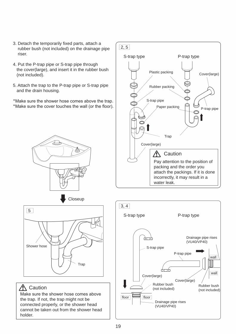
3. Detach the temporarily fixed parts, attach a rubber bush (not included) on the drainage pipe riser.
4. Put the P-trap pipe or S-trap pipe through the cover(large), and insert it in the rubber bush (not included).
5. Attach the trap to the P-trap pipe or S-trap pipe and the drain housing.
Closeup
Caution
Caution
the trap. If not, the trap might not be connected properly, or the shower head cannot be taken out from the shower head holder.
Pay attention to the position of packing and the order youattach the packings. If it is done incorrectly, it may result in awater leak.
20
Tap & handle10
Tap cap
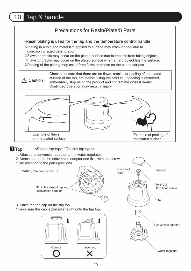
Precautions for Resin(Plated) Parts
Caution
on the plated surface the plated surface
[M4×20]Pan head screw
Tap
(Blue)
Correct
Tap1
M4×
21
Nail(long)
Tap cap
[4×16]Pan headself tapping screw
Temperaturecontrol knob
Conversion adaptor
Handle lock
Thermostat
Correct Incorrect
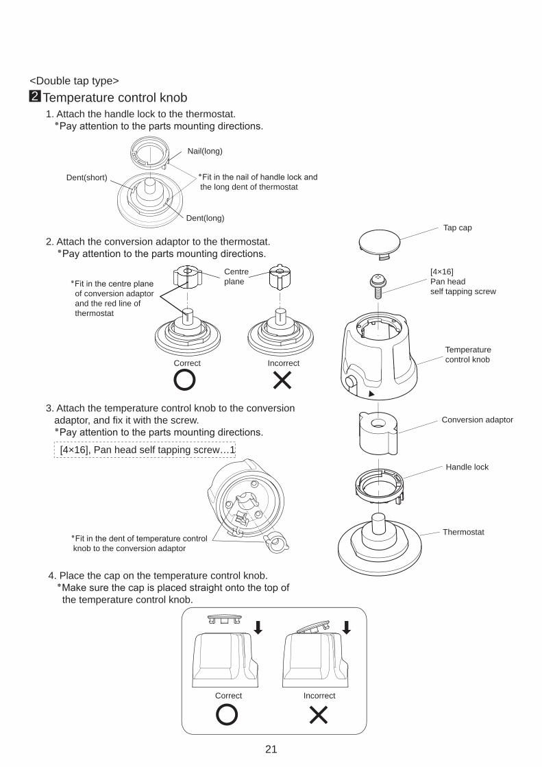
■Temperature control knob2<Double tap type>
Dent(long)
Dent(short)
Centreplane
Fit in the nail of handle lock and٭ the long dent of thermostat
Fit in the centre plane٭ of conversion adaptor and the red line of thermostat
Fit in the dent of temperature control٭ knob to the conversion adaptor
Correct Incorrect
1. Attach the handle lock to the thermostat..Pay attention to the parts mounting directions٭
2. Attach the conversion adaptor to the thermostat..Pay attention to the parts mounting directions٭
3. Attach the temperature control knob to the conversion adaptor, and fix it with the screw..Pay attention to the parts mounting directions٭
[4×16], Pan head self tapping screw…1
4. Place the cap on the temperature control knob.Make sure the cap is placed straight onto the top of٭ the temperature control knob.
22
Neck cushion11
Basin side Basin side
Chair side
Caution
Chair side
Overhead view
Neck cushionCutaway
Neck fittings
Neck fittings
Chair side
Adjust theheight
Adjust theheight
Cutaway
HookFix the hooks at thebottom of neck fittiings
Cutaway
Chair side
Basin side
come to the chair side.
Neck base Basin side
Chair side
Washer(5×20×2.0)
come to the chair side.
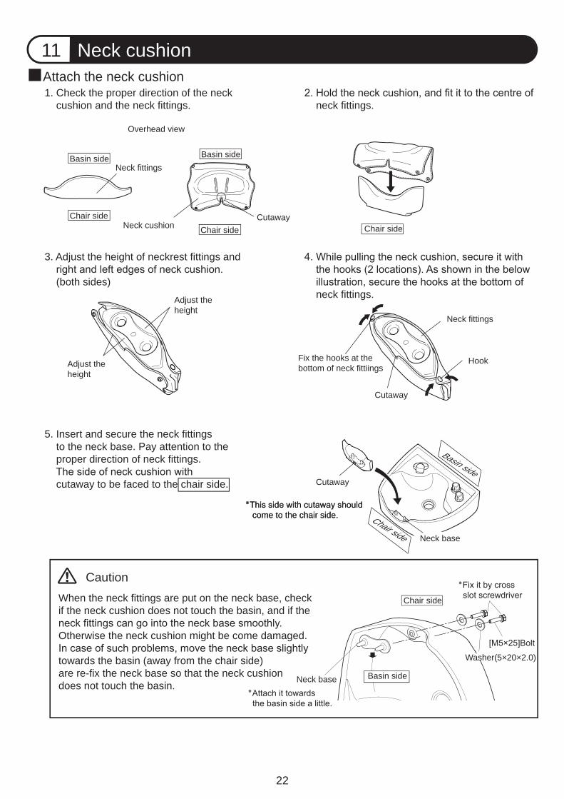
When the neck fittings are put on the neck base, checkif the neck cushion does not touch the basin, and if the
Otherwise the neck cushion might be come damaged.
towards the basin (away from the chair side)are re-fix the neck base so that the neck cushiondoes not touch the basin.
1. Check the proper direction of the neck cushion and the neck fittings. neck fittings.
3. Adjust the height of neckrest fittings and
(both sides) neck fittings.
5. Insert and secure the neck fittings to the neck base. Pay attention to the proper direction of neck fittings.
cutaway to be faced to the chair side.
Attach the neck cushion
Neck base
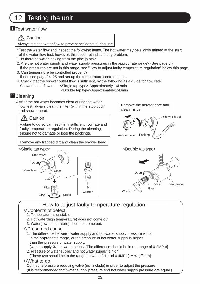
Always test the water flow to prevent accidents during use.
23
Testing the unit12
Shower head
Test water flow1
Cleaning2
PackingAerator core
Close
Open
WrenchFilter
WrenchCloseOpen
Open
CloseWrench
Stop valve
Remove the aerator core andclean inside
Remove any trapped dirt and clean the shower head
<Single tap type> <Double tap type>
of the water flow test, however, this does not indicate any problem.1. Is there no water leaking from the pipe joints?2. Are the hot water supply and water supply pressures in the appropriate range? (See page 5 ) If the pressures are not in this range, see ”How to adjust faulty temperature regulation” below this page.3. Can temperature be controlled properly? If not, see page 24, 25 and set up the temperature control handle4. Check that the shower outlet flow is sufficient, by the following as a guide for flow rate. Shower outlet flow rate: <Single tap type> Approximately 16L/min <Double tap type>Approximately15L/min
After the hot water becomes clear during the water flow test, always clean the filter (within the stop cock) and shower head.
Failure to do so can result in insufficient flow rate and faulty temperature regulation. During the cleaning, ensure not to damage or lose the packings.
Caution
Caution
How to adjust faulty temperature regulationContents of defect
Presumed cause
What to do
1. Temperature is unstable.2. Hot water(high temperature) does not come out.3. Water(low temperature) does not come out.
1. The difference between water supply and hot-water supply pressure is not in the appropriate range, or the pressure of hot water supply is higher than the pressure of water supply. [water supply hot water supply (The difference should be in the range of 0.2MPa)]2. Pressure of water supply and hot water supply is high [These two should be in the range between 0.1 and 0.4MPa(1~4kgf/cm )]
Connect a pressure reducing valve (not include) in order to adjust the pressure.(It is recommended that water supply pressure and hot water supply pressure are equal.)
Stop valveFilter
2
24
Open
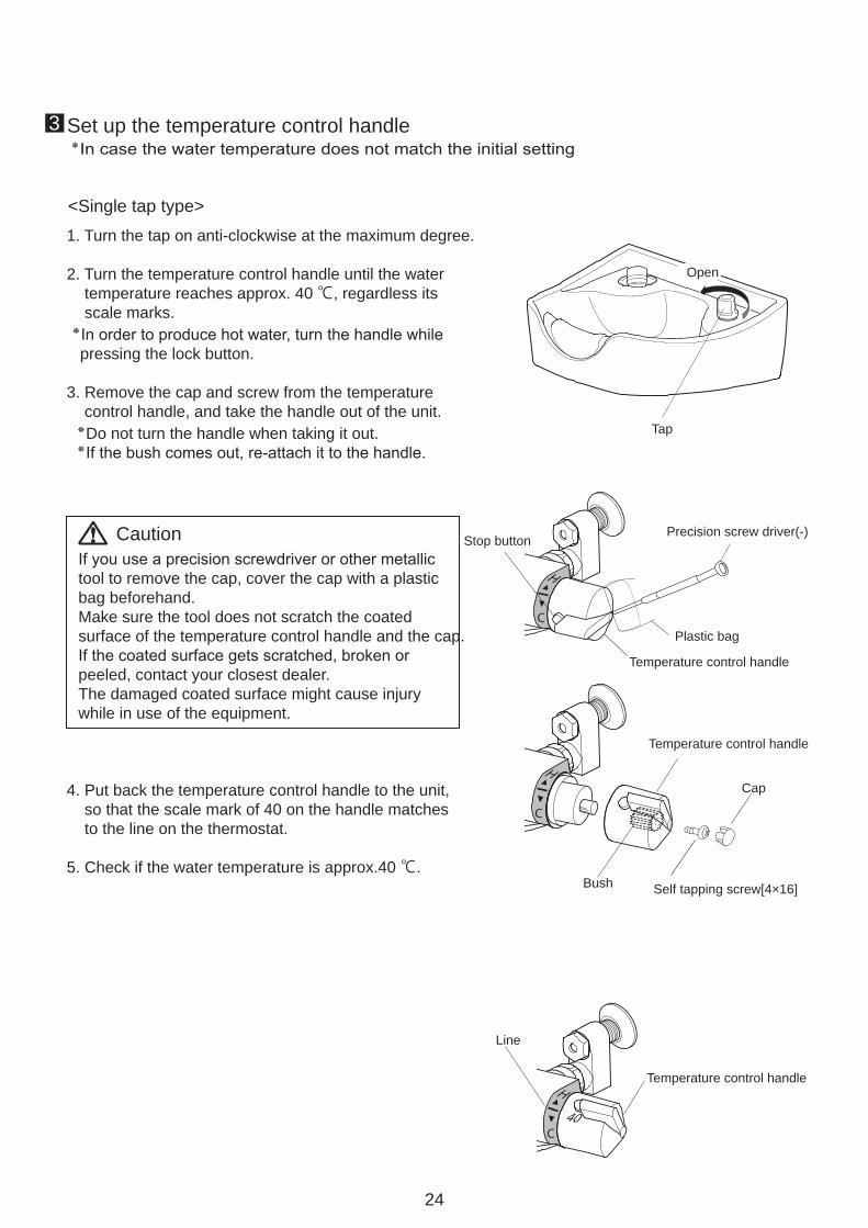
Set up the temperature control handle3
Tap
Stop buttonCaution
Plastic bag
Temperature control handle
Precision screw driver(-)
Temperature control handle
Bush
Cap
Self tapping screw[4×16]
Line
Temperature control handle
<Single tap type> 1. Turn the tap on anti-clockwise at the maximum degree.
2. Turn the temperature control handle until the water temperature reaches approx. 40 ℃, regardless its scale marks.
pressing the lock button.
3. Remove the cap and screw from the temperature control handle, and take the handle out of the unit.
Do not turn the handle when taking it out.
4. Put back the temperature control handle to the unit, so that the scale mark of 40 on the handle matches to the line on the thermostat.
5. Check if the water temperature is approx.40 ℃.
tool to remove the cap, cover the cap with a plastic bag beforehand.Make sure the tool does not scratch the coatedsurface of the temperature control handle and the cap.
peeled, contact your closest dealer. The damaged coated surface might cause injury while in use of the equipment.
C
H
C
H
C
H
40
25
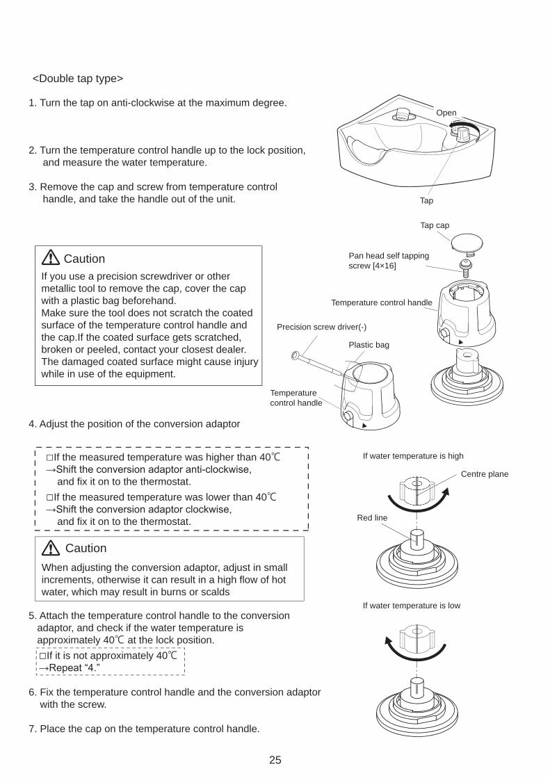
Precision screw driver(-)
Tap
Open
Tap cap
Pan head self tappingscrew [4×16]
Plastic bag
Temperaturecontrol handle
Temperature control handle
Centre plane
Red line
If water temperature is high
<Double tap type>
1. Turn the tap on anti-clockwise at the maximum degree.
2. Turn the temperature control handle up to the lock position, and measure the water temperature.
3. Remove the cap and screw from temperature control handle, and take the handle out of the unit.
If you use a precision screwdriver or other metallic tool to remove the cap, cover the cap with a plastic bag beforehand.Make sure the tool does not scratch the coatedsurface of the temperature control handle and the cap.If the coated surface gets scratched, broken or peeled, contact your closest dealer. The damaged coated surface might cause injury while in use of the equipment.
Caution
4. Adjust the position of the conversion adaptor
If the measured temperature was higher than 40℃
and fix it on to the thermostat.If the measured temperature was lower than 40℃
and fix it on to the thermostat.
CautionWhen adjusting the conversion adaptor, adjust in small increments, otherwise it can result in a high flow of hot water, which may result in burns or scalds
5. Attach the temperature control handle to the conversion adaptor, and check if the water temperature is approximately 40℃ at the lock position. If it is not approximately 40℃
6. Fix the temperature control handle and the conversion adaptor with the screw.
7. Place the cap on the temperature control handle.
If water temperature is low
26
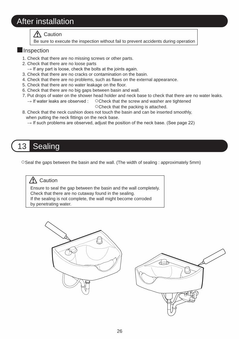
Sealing13
After installation
Inspection
CautionBe sure to execute the inspection without fail to prevent accidents during operation
CautionEnsure to seal the gap between the basin and the wall completely.Check that there are no cutaway found in the sealing.If the sealing is not complete, the wall might become corroded by penetrating water.
Seal the gaps between the basin and the wall. (The width of sealing : approximately 5mm)
1. Check that there are no missing screws or other parts.2. Check that there are no loose parts
3. Check that there are no cracks or contamination on the basin.4. Check that there are no problems, such as flaws on the external appearance.5. Check that there are no water leakage on the floor.6. Check that there are no big gaps between basin and wall.7. Put drops of water on the shower head holder and neck base to check that there are no water leaks.
Check that the screw and washer are tightened Check that the packing is attached.8. Check that the neck cushion does not touch the basin and can be inserted smoothly, when putting the neck fittings on the neck base.

27
Memo

28
1-1, 2-Chome, Higashi-shinsaibashi,Chuo-ku,Osaka,Japan
Printed in Japan
TAKARA BELMONT CORPORATIONTEL : (06) 6213-5945 FAX : (06) 6212-3680
1A0LJ1A0