NOVEMBER 2016
MAGNUMSTONEretaining walls installation manual
/ 2 /
AUSTRAL MASONRY
CONTENTS04 Overview
07 UnitSpecifications
08 Installation
08 – Gravity MagnumStone Wall
16 – Geogrid Reinforced MagnumStone Wall
20 – MagnumStone Positive Connection
22 – MagnumStone Wall
28 – MagnumStone Top Of Wall
30 We Are Brickworks
Magnumstone Installation Guide

/ 3 /
MAGNUMSTONE INSTALLATION GUIDE

/ 4 /
AUSTRAL MASONRY
MAGNUMSTONEOverview
Design Advantage
Installation Advantage
Economic Advantage
· MagnumStone units are made from high strength, wet cast concrete that provides durability and resistance to weathering.
· MagnumStone’s large vertical and horizontal hollow cores reduce efflorescence problems and the use of costly pigments.
· MagnumStone units provide excellent solutions for gravity, geogrid reinforced, steel/concrete, plantable and other types of wall structures.
· MagnumStone units are nearly half the weight per face foot of solid block systems, providing superior environmental advantages both by using far less concrete in manufacturing and by the resulting efficiency of transportation.
· MagnumStone provides superior flexibility in creating curves, corners, steps and terraced walls.
The MagnumStone retaining wall system was developed with the installer in mind. MagnumStone’s durable, high shear strength concrete SecureLugs fit into the lower units’ hollow cores, allowing significant lateral movement without losing
unit to unit interlock. Tapered sides make it easy to build tight curves and straight walls with complete accuracy. MagnumStone’s large vertical and horizontal hollow cores filled with gravel, along with its high strength SecureLug,
provide a superb geogrid to block connection.
MagnumStone is committed to providing complete technical and construction information to installers and engineers to ensure the successful completion of any retaining wall project. Your best choice is MagnumStone for value, beauty,
durability, ease of construction, and complete retaining wall excellence.
· A small crew can easily install 74 to 140 square meters of wall a day
· The one-step SecureLug system outperforms the pins or clip method, speeding up installation time considerably.
· MagnumStone’s hollow core makes it easy to saw cut, add special lighting, or place fence posts into when adding creative details.
· MagnumStone system will save time, labor, and material costs.
· MagnumStone walls can cost considerably less than conventional cast in place concrete walls or traditional masonry systems.
· MagnumStone light-weight, hollow core units are less expensive to ship and handle.
· MagnumStone labor and equipment costs are low because no special equipment is required and semi-skilled workers will find the units easy to install

/ 5 /
MAGNUMSTONE INSTALLATION GUIDE
· A small crew can easily install 74 to 140 square meters of wall a day
· The one-step SecureLug system outperforms the pins or clip method, speeding up installation time considerably.
· MagnumStone’s hollow core makes it easy to saw cut, add special lighting, or place fence posts into when adding creative details.
MAGNUMSTONEOverview
Vertical Hollow Core
SecureLug Connection
Horizontal Hollow Core
Vertical SecureLug
Vertical System
Batter SecureLug
Batter System

/ 6 /
AUSTRAL MASONRY

/ 7 /
MAGNUMSTONE INSTALLATION GUIDE
MAGNUMSTONEUnit Specifications
Dimensions: 1219 W x 610 H x 610 D (mm)
Face Area: 0.74sq m
Volume of Voids: 0.180sq m
Gravel/Filled Weight: 975kg
Batter/Set Back: 4.5º
5cm/Unit and Vertical Opt Available
Dimensions: 1219 W x 305 H x 610 D (mm)
Face Area: 0.37sq m
Colume of Voids: 0.09sq m
Gravel/Filled Weight: 490kg
Batter/Set Back: 4.5º
2.5cm/Unit and Vertical Opt Available
Standard Unit
Weight: 621kg
Half High Unit
Weight: 340kg
Standard Base Unit
Weight: 621kg
Half High Base Unit
Weight: 328kg
Standard Top Unit
Weight: 533kg
Half High Top Unit
Weight: 308kg
Step/CapDimensions: 660 TFW x 711 BFW x 610 H
x 51 TNF x 102 BNF mm Face Area: 0.434m²
Weight: 154kg
Half High Corner/End UnitDimensions: 686 TFW x 711 BFW x 610 H x
76 TNF x 102 BNF cm Face Area: 0.4217m²
Weight: 77kg
*Weights and dimensions are nominal. Specifications may change. Verify exact information with your local producer.

/ 8 /
AUSTRAL MASONRY
GRAVITY MAGNUMSTONE WALLOverview
Gravity (SRW) segmental retaining wall systems are structures lower in height that use the MagnumStone™ unit weight combined with gravel core infill to resist earth pressures behind and on top of the wall. The 4.5 degree batter or setback of the MagnumStone™ wall along with proper soil conditions below and behind the wall provide the stability of the structure. For walls 1.2m and taller a qualified engineer should be consulted.
/ 9 /
MAGNUMSTONE INSTALLATION GUIDE
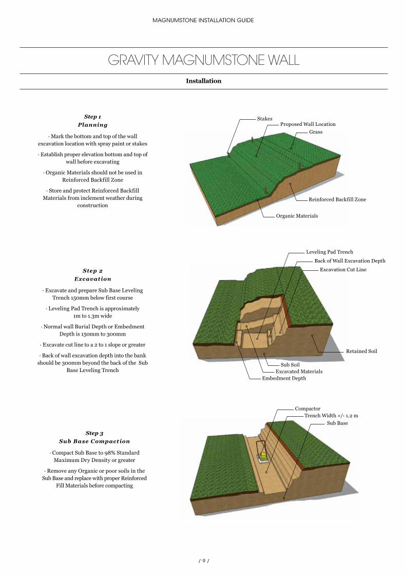
GRAVITY MAGNUMSTONE WALLInstallation
Proposed Wall LocationStakes
Reinforced Backfill Zone
Grass
Organic Materials
Leveling Pad Trench
Retained Soil
Sub Soil
Back of Wall Excavation Depth
Excavation Cut Line
Embedment DepthExcavated Materials
CompactorTrench Width +/- 1.2 m
Sub Base
Step 2 Excavation
· Excavate and prepare Sub Base Leveling Trench 150mm below first course
· Leveling Pad Trench is approximately 1m to 1.3m wide
· Normal wall Burial Depth or Embedment Depth is 150mm to 300mm
· Excavate cut line to a 2 to 1 slope or greater
· Back of wall excavation depth into the bank should be 300mm beyond the back of the Sub
Base Leveling Trench
Step 1Planning
· Mark the bottom and top of the wall excavation location with spray paint or stakes
· Establish proper elevation bottom and top of wall before excavating
· Organic Materials should not be used in Reinforced Backfill Zone
· Store and protect Reinforced Backfill Materials from inclement weather during
construction
Step 3Sub Base Compaction
· Compact Sub Base to 98% Standard Maximum Dry Density or greater
· Remove any Organic or poor soils in the Sub Base and replace with proper Reinforced
Fill Materials before compacting

/ 10 /
AUSTRAL MASONRY
GRAVITY MAGNUMSTONE WALLInstallation
Leveling Pad TrenchBase Stabilization Fabric
Trench Depth 150mm
Rake for Rough GradingWell Graded Gravel +/- 150mm Deep
CompactorCompacted Gravel Leveling Pad
Step 4Base Stabilization
· (Optional) place 2m wide Base Stabilization Fabric on top of leveling
pad trench
· Base Stabilization Fabrics will help prevent sub base materials from mixing with the gravel
base leveling pad during compaction
· Fabric also provides extra Structural Bearing Stability to the base leveling pad
Step 5 Rough Leveling Pad
· Place well graded gravel on top of fabric in the leveling pad trench approximately 150mm deep
· Rough grade gravel with a rake close to finish base elevation
Step 6 Compact Leveling Pad
· Compact Gravel Leveling Pad to 98% Standard Maximum Dry Density or greater
· Correct Moisture Content in the gravel will help in reaching proper compaction

/ 11 /
MAGNUMSTONE INSTALLATION GUIDE
Screed PipeScreed Board or Straight Edge
Short Level
Long Level
Screed PipeShovel
Compacted Gravel Leveling Pad
Extra Gravel
Screed Board or Straight Edge
Screeded Leveling Pad
Screed Pipe
Step 7 Level Screed Pipes
· Place first 1.22m long Screed Pipe across the trench at one end of the wall or at the lowest elevation
· Scratch a trench for the pipe in the compacted gravel with a chipping hammer
· Use a short level or Laser Level to set the Screed Pipe to the proper level
· Gravel is added underneath and around the Screed Pipe to support while leveling
· Place the second Screed Pipe across the trench approximately 3m from the first Screed Pipe
· Level the second Screed Pipe to the same elevation as the first Screed Pipe by using a long level on top of a Screed
Board, Straight Edge or with a Laser Level
· Continue to place and level Screed Pipes the full length of the trench leveling pad or until reaching a base elevation
change
Step 8Extra Gravel
· Place or remove extra Well Graded Gravel level to the top of the Screed Pipes as needed
· (If more than 35mm inches of loose gravel is added, repeat the compaction steps again before screeding)
Step 9Screeding Leveling Pad
· Screed the gravel leveling pad with a Screed Board or Straight Edge across the trench on top of two Screed Pipes
· The coarser the gravel the more back and forth the screeding action when drawing the Screed across the
leveling pad
· Too much pressure on the screed straight edge may dislodge the level of the screed pipes while screeding
· A second screed pass may be needed to insure an accurate level has been achieved
· Continue to screed the leveling pad until completing the full length of the
trench or up to the first elevation change
GRAVITY MAGNUMSTONE WALLInstallation

/ 12 /
AUSTRAL MASONRY
Step 10Removed SecureLugs
· MagnumStone™ base units, placed on the leveling pad, are manufactured without
SecureLugs
· Place each unit on top of the leveling pad in such a way as not to disturb the level gravel
Step 11Lay First Course
· Remove the Screed Pipes from the leveling pad
· Place a steel stake at either end of the leveling pad to establish the back of the first course of
units
· Secure tightly a string line to the stakes at either end which will provide the guide to line up the back of each MagnumStone™ base unit
· The distance of the string line between the steel stakes may vary due to heavy winds
Toe of WallImpermeable Material
Hollow Core Impermeable MaterialStep 12
Impermeable Fill
· Backfill behind, in front (toe of wall) and in the hollow cores of the units with Impermeable
Materials up to the desired level of the Perforated Drain Pipe
· Compact the impermeable materials behind, in front and in the hollow cores of the units
Steel Stake with String Line Attached
MagnumStone Base Units Are Manufactured without SecureLugs
GRAVITY MAGNUMSTONE WALLInstallation

/ 13 /
MAGNUMSTONE INSTALLATION GUIDE
Step 13Drain Pipe Outlet
· Perforated Drain Pipe should have adequate slope to drain water in the right direction
towards each Drain Pipe Outlet
· Drain Pipe Outlet can be every 10m or 15m
· Perforated Drain Pipe, laid in the Horizontal Cores, can be a Sock Wrapped system to help
prevent fines from migrating into the pipe
Burial Depth Compact the Backfill Before Placing Bluemetal / Drainage Aggregate
Perforated Drain PipeHorizontal Hollow Cores
Drain Pipe Outlet
Slope
GRAVITY MAGNUMSTONE WALLInstallation
Step 14 Backf ill
· Place and compact Backfill Materials in maximum Lifts of 200mm
· Lifts may be less than 200mm depending on the type of soil or size of equipment
· Each Lift should be compacted to 98% Standard Maximum Dry Density or greater
· The correct Moisture Content in the Backfill Materials will help in reaching proper
Compaction Density

/ 14 /
AUSTRAL MASONRY
MagnumStone Course 2
Clear Crush Drain Gravel
Bluemetal / Drainage Aggregate Placed 50mm Below Top of Units
Broom
GRAVITY MAGNUMSTONE WALLInstallation
Step 15Drainage Gravel
· Bluemetal / Drainage Aggregate is placed in the vertical and horizontal hollow cores after placing
and compaction of the backfill materials
· The Drainage Aggregate should be 50mm below the top of units to allow for
SecureLug connection
· Clear Crush Drain Gravel does not need to be compacted
· Sweep the top of the MagnumStone™ units clean of all rock and dirt before placing second
course of MagnumStone™ units
· Make sure the Backfill Materials directly behind the wall are placed flush to the top of the
units
· Make sure the Backfill Materials are well compacted and level as possible
Step 16Continue Installation
· Continue to install each course of units following the same steps as above
· Install and compact Backfill Materials in 200mm Lifts until wall is complete

/ 15 /
MAGNUMSTONE INSTALLATION GUIDE
Bluemetal / Drainage Aggregate Placed 50mm Below Top of Units
*Final determination of the suitability of the contemplated use, and its manner of use are the sole responsibility of the user
Soil Separation Filter Fabric
Swale
MagnumStone Top Unit
Bluemetal / Drainage Aggregate
GRAVITY MAGNUMSTONE WALLInstallation
Step 17Top of Wall Units
· Complete the top of the wall with MagnumStone™ Top Units
· MagnumStone™ Top Units are manufactured with the back panel 204mm lower than the front
face panel
· The Bluemetal / Drainage Aggregate and backfill materials will be placed flush to the top
of lowered back panel. There are times when more than 204mm of top soils may be required
Step 18 Soil Separation Fabric
· Place a 1.83mt wide Soil Separating Filter Fabric on top of the backfill and drainage gravel
and against the back of the last units before placing the planting soils
· The fabric will prevent planting soil fines from staining the face of the wall and migrating into the Bluemetal / Drainage Aggregate (Angular
Aggregate free of fines)
Step 19 Final Grading
· Insure that final grading is done on top and bottom of the wall
· Make sure to protect newly placed planting soil from erosion during heavy rains or
surface runoff

/ 16 /
AUSTRAL MASONRY
GEOGRID REINFORCED MAGNUMSTONE WALLSOverview
Creating a MagnumStone™ reinforced wall system, involves the use of geogrids for reinforcement. MagnumStone™ walls 1.2m and taller will automatically have active pressures because of their height. Walls smaller than 1.2m may also require geogrid reinforcement
depending on other related factors. Parking lots, roadways, or positive slopes above walls for example, require the use of reinforcement to help resist the increased pressure behind the wall. Geogrid used with the appropriate lengths, layers, and compacted backfill materials
will resist these active forces above and behind the wall. For walls 1.2m and taller a qualified engineer should be consulted.

/ 17 /
MAGNUMSTONE INSTALLATION GUIDE
Embedment Depth
Excavated MaterialsSub Base
Retained Soil
Leveling Pad TrenchBack of Wall Excavation Depth
Excavation Cut Line
Geogrid Reinforcement Cut in Lengths Designed by Engineer
Geogrid Reinforcement
Geogrid Strength Orientation
Correct Geogrid Strength Orientation
GEOGRID REINFORCED MAGNUMSTONE WALLSInstallation
Step 1Planning
· Excavate and prepare Sub Base Leveling Trench 150mm below first course
· Leveling Pad Trench is approximately 1m to 1.3m wide
· Normal wall Burial Depth or Embedment Depth is 300mm to 600mm or one block (for
more information refer to design manual)
· Excavate cut line to a 2 to 1 slope or greater
· Back of wall excavation depth into the bank at the base of the wall should be from the face of
wall to the designed length of Geogrid
Step 2Cut Geogrid
· Cut Geogrid Reinforcement to the length specified in the design
· Geogrids are manufactured in two directions Uni-axial or Bi-axial. Uni-axial grid has one
direction of strength and that direction has to be oriented perpendicularly to the face of the wall during installation. Bi-axial grid can be
laid in two directions, perpendicular and lengthwise to the face of wall (ensure that the
lengthwise direction is still in accordance to the length specified by the Engineer’s design)
· Correct geogrid orientation, strength and length is crucial to the success of the wall
project
· Each Geogrid length should be laid parallel and adjacent to each other but never overlapping

/ 18 /
AUSTRAL MASONRY
Geogrid Elevations Set to Engineer Design
No Greater Than 200mm LiftsSecureLug Geogrid Connection
Stakes Placed to Maintain Geogrid TensionTensioned Geogrid
Bluemetal / Drainage Aggregate
GEOGRID REINFORCED MAGNUMSTONE WALLSInstallation
Step 3 Lay Geogrid
· Place the Geogrid as far forward on the MagnumStone™ units as possible without
revealing it on the face
· Place the next course of MagnumStone™ units on top of the lower units and Geogrid at a half
bond to the lower units
· The two SecureLugs will fit securely into the hollow cores of the two units below and lock the
Geogrid into the gravel core
· The gravel in the lower units will be recessed 50mm or more to allow for the SecureLugs
connection
· Complete the installation of units on the Geogrid Reinforced courses
· Make sure each unit is installed against the unit next to it leaving no gaps between unit
joints
· Use stakes or backfill materials to maintain the tension of the Geogrid during backfilling
· Do not drive equipment directly on top of Geogrid
Step 4Reinforced Backf ill
· Backfill the Reinforced Zone by placing materials from the back of the wall towards
the end of the Geogrid
· Install drainage gravel in the cores after placing and compacting backfill materials
· Install and compact backfill materials in Lifts no greater than 200mm until wall is complete
Reinforced Zone

/ 19 /
MAGNUMSTONE INSTALLATION GUIDE
No Greater Than 200mm Lifts

/ 20 /
AUSTRAL MASONRY
MAGNUMSTONE POSITIVE CONNECTIONOverview
One single length of geogrid is wrapped through the hollow core providing equal length reinforcement at the bottom and top of a single MagnumStone™ unit. The geogrid wrapped hollow core is then filled with gravel making this the ultimate
geogrid positive connection.

/ 21 /
MAGNUMSTONE INSTALLATION GUIDE
MAGNUMSTONE POSITIVE CONNECTIONInstallation
Step 1Lay f irst course
· Geogrid positive reinforcement will be cut in .61m wide strips and twice the length specified in the design plus .61m for the unit height. (if
specified Geogrid length is 3m the length will be 6.6m long)
· Place the base units vertical open core over the half rolled length of Geogrid. Make sure the
Geogrid is placed to the correct design length, perpendicular and centered to the unit before
placing MagnumStone™
Step 2Compact Backf ill
· Backfill and compact the Reinforced Zone by placing materials from the back of the wall towards the end of the Geogrid. Install and compact Backfill Materials in 200mm Lifts
Step 3Wrap geogrid
· Pull rolled Geogrid out of the vertical core and place perpendicular to top of first unit on top of
compacted backfill. Tension Geogrid before installing drainage gravel. Install the Bluemetal
/ Drainage Aggregate 50mm below the top of units to allow for Securelug connection
Step 4Lay second course
· Place the second MagnumStone™ units vertical open core over the second layer of half rolled Geogrid. Make sure Geogrid is placed to the
correct design length perpendicular to the unit and centered to the two adjacent Geogrid strips
before placing the unit
· Repeat above steps for each course of MagnumStone™ Positive Reinforced Wall

/ 22 /
AUSTRAL MASONRY
MAGNUMSTONE WALLOverview
This section provides detailed, illustrated step-by-step instructions for using MagnumStone™ to construct wall details including: inside curves, outside curves,
elevation changes, and both inside and outside corners.
Curves, corners and elevation changes are the portions of a wall project that adapt to the specifics of the site and the needs of its users. Correct construction and professional
completion of these wall details greatly enhances the visual appeal of the finished project and avoids the time and costs associated with improper installation.

/ 23 /
MAGNUMSTONE INSTALLATION GUIDE
Second Standard Unit
Half High Base Unit
Standard Base Unit
First Standard Unit
Last Standard Base UnitHalf High Leveling Pad
First Half High Base UnitSecond Half High Base Unit
Half High Base Unit
MAGNUMSTONE WALLInstallation
Step 1Base Elevation Changes
· The top of the last Standard Base Unit will be used to establish the Half High Base Units
gravel leveling pad elevation
· Make sure to backfill and compact the gravel in and around the last Standard Base Unit
· Finished grade of the leveling pad should be 4mm to 8mm above half the height of the last
Standard Base Unit to allow for a small amount of settlement to the first
Half High Base Unit
· Repeat steps 5 through 9 in the gravity section on preparing the step up gravel leveling pad
Step 2Lay Elevation Changes
· Place the first Standard Unit, (with SecureLugs), on the second course at a half bond on top of last & second last Half High Base Units
· The two SecureLugs will fit into the hollow cores of the two Half High Units below. To align
the wall, place a string line at the back of the units for a straight wall or place a PVC Flex Pipe for a curved wall
· The batter or set back will be 50mm/unit (4.5 degree)
· Place the second Standard Unit half on the last Half High Unit and half on the gravel leveling pad. Ensure that the SecureLug is removed on
the leveling pad side of the unit
· Complete the installation of the MagnumStone™ units in either direction of the
elevation change
· Make sure each unit is in line and laid tight to each other

/ 24 /
AUSTRAL MASONRY
MAGNUMSTONE WALLConvex/Outside Curves
Step 1Convex First Course
· If possible, start building a curve from the center and work left and right
through the curve
· Use PVC Flex Pipes to create smooth and accurate Convex curves
· Use the back of the unit for alignment
· Build each course of units by starting at the same place and the same bond
as the last course
· Convex curves have a slight increase in batter or setback to the standard 50mm/unit
· The taller the wall the larger the Convex first course needs to be. The radius of each
additional course will be slightly smaller than the lower course
· MagnumStone™ minimum Convex curve is approximately 4m radius
Step 2Convex Geogrid Curve
· Each Geogrid length should be laid perpendicularly to the wall face
· Geogrid should not overlap on the MagnumStone™ units
· Correct geogrid orientation, strength and length is crucial to the success
of the wall project
PVC Flex PipeFirst Course
Smaller Radius
Larger Radius
Work LeftStart Center of Curve Work Right
+/- 75mm Backfill Materials Between Geogrid Overlaps
Do Not Overlap Geogrid on MagnumStone Units
Center of Curve
Min Convex Radius 3.7m

/ 25 /
MAGNUMSTONE INSTALLATION GUIDE
MAGNUMSTONE WALLConcave/Inside Curves
Step 1Concave First Course
· If possible, start building a curve from the center and work left and right
through the curve
· Use PVC Flex Pipes to create smooth and accurate Concave curves
· Use the back of the unit for alignment
· Build each course of units by starting at the same place and the same bond as
the last course
· Concave curves have a slight decrease in batter or setback to the standard 50mm/unit
· The taller the wall the smaller the Concave first course needs to be. The radius of each additional
course will be slightly larger than the lower course
Step 2Concave Geogrid Curve
· Each Geogrid length should be laid perpendicularly to the wall face
· Geogrid should not overlap on the MagnumStone™ units
· To ensure 100% coverage, place a second layer of Geogrid centered to the unreinforced
triangle zone one course above the main Geogrid layer
· Correct geogrid orientation, strength and length is crucial to the success of the wall
project
PVC Flex PipeCenter of Curve
First Course
Unreinforced Triangle Zone
Work LeftStart Center of Curve
Work Right
Main Geogrid Layer
Geogrid Placed at Center to Unreinforced Triangle Zone
Secondary Geogrid Layer
Larger Radius
Smaller Radius

/ 26 /
AUSTRAL MASONRY
MAGNUMSTONE WALLOutside 90º Corners
Step 1Outside First Course
· Use a Corner/End Unit to build an outside corner
· Attach a Left Corner/End Unit to the first MagnumStone™ base unit and place assembled
corner unit on base leveling pad to start the outside corner
· Place a MagnumStone™ unit on either side against the Corner/End Unit
· Continue to lay the MagnumStone™ base course on either side of the corner until first
course is completed
· Attach a Right Corner/End Unit to a MagnumStone™ standard unit (with
SecureLugs) and place on second course overlapping lower corner unit. Align the second
course corner unit with lower corner unit to achieve proper setback
· Continue to lay the MagnumStone™ second course on either side of the
corner until second course is completed
Step 2Outside Geogrid Corner
· Each Geogrid length should be laid perpendicularly to the wall face
· Geogrid should not overlap on the MagnumStone™ units
· Lay the 1st Geogrid corner section perpendicularly to one side of the corner
· Lay the 2nd Geogrid section perpendicularly to the other side of the corner but not overlapping
the 1st Geogrid section
· Lay the secondary Geogrid layer one course above and perpendicular to the lower main
Geogrid layer directional strength
· Correct geogrid orientation, strength and length is crucial to the success
of the wall project
1st Course 2nd Course
Right Corner/End Unit
2nd Geogrid Corner Section
Geogrid Layers Should Not Overlap
1st Geogrid Corner Section
Secondary Geogrid Layer (One Piece)
Main Geogrid Layer
Left Corner/End Unit

/ 27 /
MAGNUMSTONE INSTALLATION GUIDE
MAGNUMSTONE WALLInside 90º Corners
Step 1Inside First Course
· Place the second unit at right angle and centered to the first MagnumStone™ base unit. Continue to install the MagnumStone™
base units right and left of the first inside corner units
· Place the second unit at right angle and centered to the 1st unit on the second course
· Make sure second course units are placed at a 50mm/unit setback to the lower inside corner
· Continue to install the units left and right of the inside corner to complete the second course
of the wall
· Repeat the above step by step installation until the wall height is completed or until reaching
the first Geogrid layer
Step 2Inside Geogrid Corner
· Each Geogrid length should be laid perpendicularly to the wall face
· Geogrid should not overlap on the MagnumStone™ units
· Lay the 1st Geogrid corner section perpendicularly to one side of the corner and
overlap h/4 through the backfill (Height of Wall ÷ 4)
· Lay the 2nd Geogrid section perpendicularly to the 1st Geogrid
· Lay the second Geogrid layer perpendicularly and overlap h/4 through the backfill opposite to
the first Geogrid layer
· The h/4 overlap will alternate layer to layer to properly secure the inside corner
· Correct geogrid orientation, strength and length is crucial to the success of the wall
project
2nd Base Unit Centered
1st Base Unit
50mm
1st Geogrid Section
Height/4 Overlap Through the Backfill
2nd Geogrid Section
Second Geogrid Section
Second Course Staggered 50mm
First Geogrid Layer
Second Geogrid Layer

/ 28 /
AUSTRAL MASONRY
Once again the large hollow cores provide yet another solution. This time it facilitates the easy embedment of traffic barriers, railings, fences or even large “Jersey” barriers
that projects require for top of wall safety. The top of wall details can be secured by infilling the vertical and horizontal cores with concrete. Another benefit is the
embedment system near the front of the wall face. This provides the designer and owner maximum usage of the land above the wall without sacrificing any structural
integrity.
MAGNUMSTONE TOP OF WALLOverview

/ 29 /
MAGNUMSTONE INSTALLATION GUIDE
Grass Swales
· An impermeable soil Swale can be created on top of the wall to take care of any water
that may cascade over the wall face
Concrete Swales· Concrete Swales can be placed on top of
the MagnumStone™ wall to take care of any possible surface water problems that may
damage the backfill soils
Fence Posts· Fence posts, railings or guard rails can be placed into the large vertical hollow cores
· Fill the vertical and hollow cores with concrete to the depth and length around each
post that will resist lateral force
· Check with a qualified engineer
MAGNUMSTONE TOP OF WALLDetails

/ 30 /
AUSTRAL MASONRY

/ 31 /
MAGNUMSTONE INSTALLATION GUIDE
Opposite: GB Smooth Porcelain
WE AREBrickworks
Brickworks Building Products is one of Australia’s largest and most diverse
building material manufacturers. Under the Brickworks Building Products umbrella
are some of Australia’s best known building materials brands. Our products
include bricks, pavers, masonry blocks, retaining wall systems, precast concrete panels,
concrete and terracotta roof tiles, timber products, terracotta façades
and specialised building systems.
With a broad product portfolio and manufacturing and sales facilities
across Australia, Brickworks Building Products is uniquely placed to service
the demands of the building industry.
With over 1,200 staff across Australia and New Zealand, we pride ourselves on our
commitment to product, service excellence and our leadership position.

STYLE AND FUNCTION
www.australmasonry.com.au1300 masonry (1300 627 667)
follow brickworks building products on
The product images in our brochures give a general indication of colour for your preliminary selection.We also recommend you view current product samples before making your final decision.
Partners in Design 10/2016
Austral Masonry is part of the Brickworks Group