HYUNDAI U-Series
Magnetic Contactor | Overload Relay
www.hyundai-elec.com
Head Office 1, Jeonha-dong, Dong-gu, Ulsan, Korea Tel: 82-52-202-8101~8 Fax: 82-52-202-8100
Seoul 140-2, Gye-dong, Jongno-gu, Seoul, Korea (Sales & Marketing) Tel: 82-2-746-8519, 7510 Fax: 82-2-746-7647
Orlando 4700 Millenia Blvd., Suite 370, Orlando, Florida 32839, U.S.A. Tel: 1-407-249-7350 Fax: 1-407-275-4940
New Jersey 300 Sylvan Avenue, Englewood Cliffs, NJ, 07632, U.S.A. Tel: 1-201-816-0286, 8028 Fax: 1-201-816-4083
Chicago 1090 Fargo Avenue Elk Grove Village, IL60007, U.S.A. Tel: 1-847-228-8845 Fax: 1-847-437-3574
London 2nd Floor, The Triangle, 5-17 Hammersmith Grove, London, W6 0LG, UK Tel: 44-20-8741-0501 Fax: 44-20-8741-5620
Tokyo 8th Fl., Yurakucho Denki Bldg.1-7-1, Yuraku-cho, Chiyoda-gu, Tokyo, 100-0006, Japan Tel: 81-3-3212-2076, 3215-7159 Fax: 81-3-3211-2093
Osaka I-Room 5th Fl. Nagahori-Plaza Bldg. 2-4-8, Minami Senba, Chuo-Ku, Osaka, 542-0081, Japan Tel: 81-6-6261-5766, 5767 Fax: 81-6-6261-5818
Riyadh 2nd Floor, the Plaza, P.O.Box 21840 Riyadh 11485, Saudi Arabia Tel: 966-1-462-2331 Fax: 966-1-464-4696
Dubai 205, Building 4, Emaar Square, Sheikh Zayed Road, Pobox 252458, Dubai, UAE Tel: 971-4-425-7995 Fax: 971-4-425-7996
Kuwait Floor 15, Al Sour Tower, Al Sour Street, Al-Qiblah, Kuwait Tel: 965-2291-5354 Fax: 965-2291-5355
Moscow World Trade Center, Ent. 3, #1902, Krasnopresnenskaya Nab.12, Moscow, 123610, Russia Tel: 7-495-258-1381 Fax: 7-495-258-1382
Madrid Paseo De La Castellana 216, Planta 0, 28046 Madrid, Spain Tel: 34-91-732-0454 Fax: 34-91-733-2389
Sofia 1271, Sofia 41, Rojen Blvd., Bulgaria Tel: 359-2-803-3200, 3220 Fax: 359-2-803-3203
Montgomery 600 South Court Street, Suite 316 Montgomery, AL36104, U.S.A. Tel: 1-334-230-9921 Fax: 1-334-240-6869
Yangzhong No.9 Xiandai Road, Xinba Scientific and Technologic Zone, Yangzhong, Jiangsu, P.R.C. Zip: 212212, China Tel: 86-511-8842-0666, 0212 Fax: 86-511-8842-0668, 0231
COntentsFeatures 4 · Contactor & Control Relay 9 · Thermal Overload Relay 49Dimensions 58 ·Installation 70 · Precautions 71
We build a better future!
for YOU and being neW
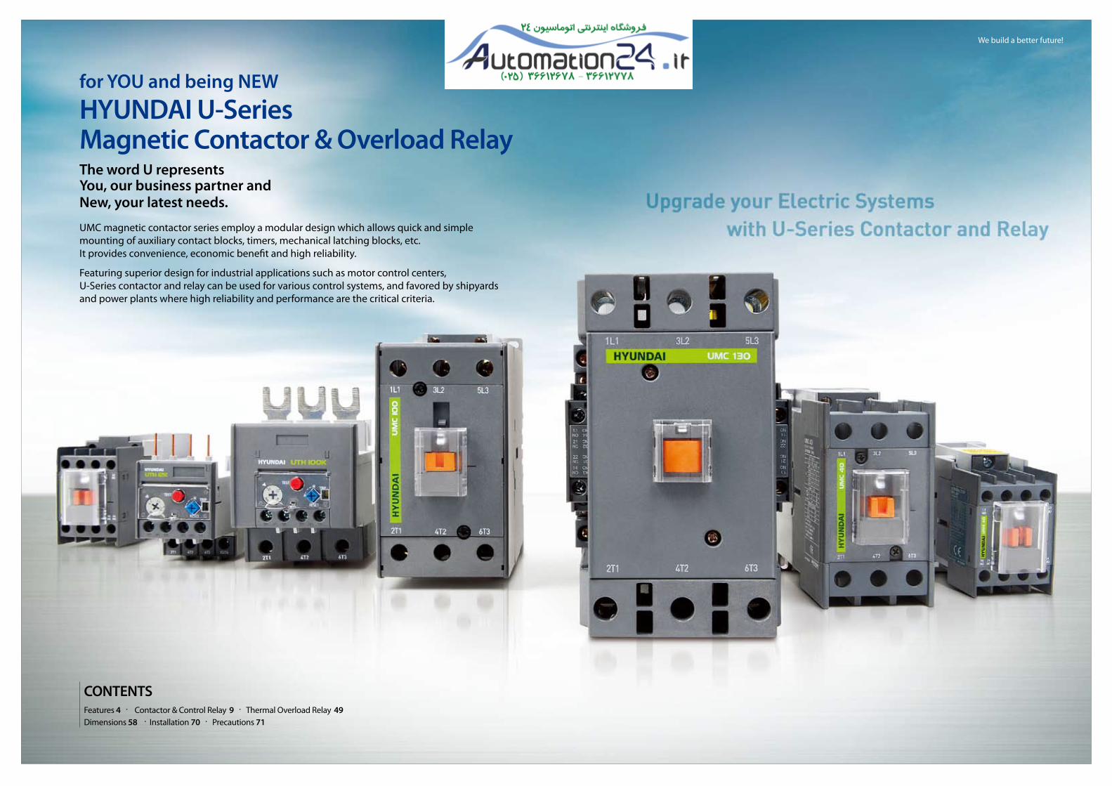
HYUnDAI U-series Magnetic Contactor & Overload Relaythe word U representsYou, our business partner and new, your latest needs.
UMC magnetic contactor series employ a modular design which allows quick and simple mounting of auxiliary contact blocks, timers, mechanical latching blocks, etc.It provides convenience, economic benefit and high reliability.
Featuring superior design for industrial applications such as motor control centers,U-Series contactor and relay can be used for various control systems, and favored by shipyardsand power plants where high reliability and performance are the critical criteria.

4 Magnetic Contactor & Overload Relay_5
HYUNDAI U-Series Magnetic Contactor l Overload Relay
Features
Connection
■ screw type : 9-800A ■ Lug type : 40-100A
35mm DIN-rail installation up to 100AF
Safety cover - IP20
Easy coil replacement
Convenient main contact inspection Light-weight by engineering plastic
Optimized arc grid
Noise free & free voltage by DC exciting method (115-800A)
CB certified by KERI (IEC60947-4-1)

Magnetic Contactor & Overload Relay_7
Cover
Arc grid
Arc chamber
Contact bridge
Moving contact
Return spring
Moving core
Coil
Coil terminal safety cover
Fixed core
FrameDamper
Front safety cover
Fixed contact
Main terminal safety cover
Main terminal safety cover
6
HYUNDAI U-Series Magnetic Contactor l Overload Relay
Features
Name plate
Arc chamber
Frame
Surge absorber installation part
Screw installation hole
Front safety cover
Side accessoryinstallation hole
DIN-rail installation part
Holder
Load side numbering
Front safety cover
Main terminal
Load side numbering
Coil terminal
Model name
external structure
Internal structure
12AF
UTH12■ Current range 0.12-12A
32AFUMC18, 25, 32■ Rated current 18, 25, 32A■ Rated insulation voltage 750V
UTH32■ Current range 0.12-32A
65AFUMC40, 50, 65■ Rated current 40, 50, 65A■ Rated insulation voltage 750V
UTH65■ Current range 7-65A
100AFUMC75, 85, 100■ Rated current 75, 85, 100A■ Rated insulation voltage 750V
UTH100■ Current range 17-100A
150AFUMC115, 130, 150■ Rated current 115, 130, 150A■ Rated insulation voltage 1000V
UTH150■ Current range 48-150A
265AFUMC185, 225, 265■ Rated current 185, 225, 265A■ Rated insulation voltage 1000V
UTH265■ Current range 48-265A
500AFUMC300, 400, 500■ Rated current 300, 400, 500A■ Rated insulation voltage 1000V
UTH400■ Current range
90-400A
UTH800■ Current range
300-500A
800AFUMC630, 800■ Rated current 630, 800A■ Rated insulation voltage 1000V
UTH800■ Current range 378-800A
UMC9,12■ Rated current 9, 12A■ Rated insulation voltage 750V
Ampere Frame

+ + + + + + + + + + + + + + + + + + + + + + + ++ + + + + + + + + + + + + + + + + + + + + + + ++ + + + + + + + + + + + + + + + + + + + + + + ++ + + + + + + + + + + + + + + + + + + + + + + ++ + + + + + + + + + + + + + + + + + + + + + + ++ + + + + + + + + + + + + + + + + + + + + + + ++ + + + + + + + + + + + + + + + + + + + + + + ++ + + + + + + + + + + + + + + + + + + + + + + +8
HYUNDAI U-Series Magnetic Contactor l Overload Relay
Features
1 7
1
9
56
33
2
4
4
Accessories
1. Contactor UMC 2. Front safety cover
3. Auxiliary contact block (Front mounting) UAB 4. Auxiliary contact block (Side mounting) UAL
5. Mechanical latching block ULB 6. Electronic timer block UET
7. Mechanical interlock unit UTL 8. Surge absorber URC/UCD
9. Thermal overload relay UTH
8
Contactor & Control Relay
※The applicable accessories of each contactor are not same as above. For exact application to each contactor, please refer to next pages.
Accessories

Magnetic Contactor & Overload Relay_11
Contactor & Control Relay
10
HYUNDAI U-Series Magnetic Contactor l Overload Relay
Rating Overview
UMC75
AC750
AC690
8
115
22/75
37/75
37/64
37/42
-
2,000
10,000
13/55
25/52
30
450
900
1,800(1,200)1)
200
400
750
750
600
600
90
-
-
25/68
60/77
50/52
2
●
UMC85
AC750
AC690
8
125
25/85
45/85
50/75
45/45
-
2,000
10,000
15/65
30/62
30
450
900
1,800(1,200)1)
200
400
850
850
680
680
105
-
-
30/80
60/77
50/52
3
●
UMC100
AC750
AC690
8
145
30/100
55/100
50/85
45/65
-
2,000
10,000
17/72
33/68
30
450
900
1,800(1,200)1)
200
400
1,000
1,000
800
800
125
-
-
30/80
60/77
75/77
3
●
UMC115
AC1,000
AC1,000
8
160
37/115
60/115
59/100
55/65
65/50
1,000
5,000
19/80
37/75
30
450
900
1,800
200
400
1,150
1,150
920
920
160
-
-
40/104
75/96
100/99
3
-
UMC130
AC1,000
AC1,000
8
180
40/130
65/130
70/120
75/82
75/54
1,000
5,000
22/93
45/90
30
450
900
1,800
200
400
1,300
1,300
1,040
1,040
180
-
-
40/104
75/96
100/99
3
-
UMC150
AC1,000
AC1,000
8
210
45/150
75/150
90/140
90/120
90/66
1,000
5,000
30/125
55/110
30
450
900
1,800
200
400
1,500
1,500
1,200
1,200
210
-
-
50/130
100/124
125/125
4
-
UMC185
AC1,000
AC1,000
8
275
55/185
90/185
110/180
110/120
110/78
1,000
5,000
37/150
75/150
30
300
600
1,200
200
400
1,850
1,850
1,480
1,480
230
-
-
60/154
125/156
150/144
4
-
UMC225
AC1,000
AC1,000
8
315
75/225
132/225
132/200
132/150
132/96
1,000
5,000
45/185
90/185
30
300
600
1,200
200
400
2,250
2,250
1,800
1,800
260
-
-
75/192
150/180
200/192
4
-
UMC265
AC1,000
AC1,000
8
350
80/265
147/265
150/225
160/173
160/113
1,000
5,000
50/200
102/200
30
300
600
1,200
200
400
2,650
2,650
2,120
2,120
330
-
-
100/248
200/240
250/242
4
-
UMC300
AC1,000
AC1,000
8
400
90/300
160/300
200/273
200/220
200/141
1,000
5,000
55/220
110/220
30
300
600
1,200
150
300
3,000
3,000
2,400
2,400
350
-
-
100/248
250/302
250/242
5
-
UMC400
AC1,000
AC1,000
8
500
125/400
220/400
250/300
250/300
250/178
1,000
5,000
75/300
150/300
30
300
600
1,200
150
300
4,000
4,000
3,200
3,200
450
-
-
150/360
300/361
300/289
5
-
UMC500
AC1,000
AC1,000
8
550
140/500
250/500
300/426
335/360
275/192
50
500
90/350
175/350
3
300
600
1,200
150
300
5,000
5,000
4,000
4000
550
-
-
150/360
300/361
350/336
5
-
UMC630
AC1,000
AC1,000
8
750
190/630
330/500
330/500
400/412
300/213
50
500
110/400
200/400
3
300
600
1,200
150
300
6,300
6,300
5,040
5,040
750
-
-
250/480
500/477
500/382
6
-
UMC800
AC1,000
AC1,000
8
900
220/800
440/800
500/720
500/630
400/284
50
500
160/630
300/630
3
300
600
1,200
150
300
8,000
8,000
6,400
6,400
900
-
-
300/720
600/708
600/578
7
-
3NO
-
2NO+1NC
-
70 × 140 × 128
70 × 140 × 128
-
1.40
1.40
-
3NO
-
-
2NO+2NC
-
-
103 × 155 × 146
-
-
2.50
3NO
-
-
2NO+2NC
-
-
138 × 204 × 174
-
-
4.70
3NO
-
-
2NO+2NC
-
-
163 × 243 × 203
-
-
8.75
3NO
-
-
2NO+2NC
-
-
276 × 314 × 253
-
-
22
ScrewScrew & DIN-rail
※1) The value in parentheses is for direct current (DC).
Model UMC9
AC750
AC690
6
25
2.5/9
4/9
4/7
5.5/6
-
2,500
25,000
1.5/8
2.2/6
30
1,000
2,000
3,600
300
600
110
90
88
72
21
0.5/9.8
1/8
2/6.8
5/7.6
5/6.1
00
●
3NO
1NO or 1NC
1NO or 1NC
-
44 × 75 × 80
44 × 75 × 112
-
0.30
0.55
-
3NO
-
-
-
45 × 83 × 94
45 × 83 × 127
-
0.40
0.70
-
3NO
-
2NO+1NC
-
55 × 106 × 111
55 × 106 × 111
-
0.75
0.75
-
UMC12
AC750
AC690
6
25
3.5/12
5.5/12
7.5/12
7.5/9
-
2,500
25,000
2.2/11
4/9
30
1,000
2,000
3,600
300
600
130
120
104
96
21
1/16
2/12
3/9.6
7.5/11
10/11
00
●
UMC18
AC750
AC690
8
40
4.5/18
7.5/18
8.5/15
7.5/9
-
2,500
15,000
3.7/16
4/11
30
1,000
2,000
3,600
300
600
180
180
144
144
30
1.5/16
3/17
5/15.2
10/14
15/21
0
●
UMC25
AC750
AC690
8
45
5.5/25
11/25
15/22
15/18
-
2,500
15,000
3.7/18
5.5/13
30
1,000
2,000
3,600
300
600
250
250
200
200
40
2/20
3/17
10/28
20/27
15/21
0
●
UMC32
AC750
AC690
8
55
7.5/32
15/32
18.5/28
18.5/22
-
2,000
15,000
4.5/22
7.5/17
30
1,000
2,000
3,600
300
600
320
320
256
256
50
2/24
5/28
10/28
25/34
20/22
1
●
UMC40
AC750
AC690
8
60
11/40
18.5/40
22/32
22/23
-
2,000
15,000
5.5/25
11/24
30
750
1,500(900)1)
3,000(1,200)1)
250
500
400
400
320
320
60
3/34
7.5/40
15/42
30/40
30/32
1
●
UMC50
AC750
AC690
8
70
15/50
22/50
30/43
30/28
-
2,000
15,000
7.5/35
15/32
30
750
1,500(900)1)
3,000(1,200)1)
250
500
500
500
400
400
70
5/56
10/50
20/54
40/52
30/42
2
●
UMC65
AC750
AC690
8
100
18.5/65
30/65
33/60
33/35
-
2,000
15,000
11/50
22/47
30
750
1,500(900)1)
3,000(1,200)1)
250
500
650
650
520
520
80
5/56
10/50
20/54
40/52
40/52
2
●
Rated insulation voltage [Ui]
Rated operation voltage [Ue]
Rated impulse withstand current [Uimp]
Rated thermal current [Ith] (AC1)
AC200-240V
AC380-440V
AC500-550V
AC660-690V
Rated AC1,000V
current Lifetime Electrical
(440V) Mechanical
AC200-240V
AC380-440V
Electrical lifetime
100% load
Operating 50% load
frequency 20% load
(per hour) 100% load
50% load
Making capacity AC220V
AC440V
Breaking capacity AC220V
AC440V
Continuous current at 40℃
AC100-120V
Rated AC220-240V
current AC220-240V
AC440-480V
AC550-600V
NEMA size
Mounting method
Application for hoist
Main
Contacts AC
Auxiliary DC
AC/DC
AC Width ×
Dimensions DC Height ×
AC/DC Depth
AC
Weight DC
AC/DC
V
V
kV
A
kW/A
× 1,000
times
kW/A
× 1,000 times
times
times
A
A
A
HP/A
HP/A
mm
kg
IEC6
0947
UL5
08 &
CSA
Screw & DIN-rail
※1) The value in parentheses is for direct current (DC).
AC3
[Ie]
AC4
[Ie]
AC1
AC2
AC3
AC4
1 phase
3 phase

Magnetic Contactor & Overload Relay_13
Contactor & Control Relay
◆ Order information
◆ Accessories
Contactor: UMC9-12
UMC 12
Code
UMC
Series
UMC
CodeRated current
AC3, AC440V
Power
9
12
9A
12A
4kW
5.5kW
01 N S
Code Code Application Code Terminalaccessory
01
10
Auxiliary contact
0NO+1NC
1NO+0NC
N
HS Safety
cover Standard
Hoist
X220
CodeVoltage (V)
Current,frequency
X
A
D
24-440
24-480
24-250
AC, 50Hz
AC, 60Hz
DC
6
45
22
8
7
1. Front safety cover UMC100IC page 35
2. Auxiliary contact block (Front mounting) UAB page 30
3. Auxiliary contact block (Side mounting) UAL65 page 30
4. Mechanical latching block ULB100 page 33
5. Electronic timer block UET page 34
6. Mechanical interlock block UTL65 page 32
7. Surge absorber URC/UCD page 35
8. Thermal overload relay UTH12 page 50
3
3
1
12
HYUNDAI U-Series Magnetic Contactor l Overload Relay
specifications & Order Information
Contactor l UMC 9-12A
◆ Operation voltage
AC, 50Hz AC, 60Hz DC
24424880
100110120220230240380400415440
2448
100110120208220230240277380440460480
24486080
100110125200220250
(Unit: V)
Model UMC9 UMC12
AC750
AC690
6
25
2.5/9
4/9
4/7
5.5/6
-
2,500
25,000
1.5/8
2.2/6
30
1,000
2,000
3,600
300
600
110
90
88
72
●
3NO
1NO or 1NC
1NO or 1NC
44 × 75 × 80
44 × 75 × 112
0.30
0.55
AC750
AC690
6
25
3.5/12
5.5/12
7.5/12
7.5/9
-
2,500
25,000
2.2/11
4/9
30
1,000
2,000
3,600
300
600
130
120
104
96
●
Rated insulation voltage [Ui]
Rated operation voltage [Ue]
Rated impulse withstand current [Uimp]
Rated thermal current [Ith] (AC1)
AC200-240V
AC380-440V
AC500-550V
AC660-690V
Rated AC1,000V
current Lifetime
Electrical
Mechanical
AC200-240V
AC380-440V
Electrical lifetime
100% load
Operating 50% load
frequency 20% load
(per hour) 100% load
50% load
Making capacity AC220V
AC440V
Breaking capacity AC220V
AC440V
Mounting method
Application for hoist
Main
Contacts Auxiliary
AC
DC
AC
Dimensions
DC
Weight AC
DC
IEC6
0947
V
V
kV
A
kW/A
× 1,000times
kW/A
× 1,000 times
times
times
A
A
mm
kg
Screw & DIN-rail
AC3
[Ie]
AC4
[Ie]
AC1
AC2
AC3
AC4
Width ×
Height ×
Depth
◆ Contact arrangement
Item AC, DC
Contactoronly
Contactor with side mounting auxiliary
contact block1) (max.)
1NO 1NC
3NO+2NC 2NO+3NC
1L1
2T1
5L3
6T3
3L2
4T2
A1
A234
33 1L1
2T1
5L3
6T3
3L2
4T2
A1
A242
41
1L1
2T1
5L3
6T3
3L2
4T2
A1
A234
33 1L1
2T1
5L3
6T3
3L2
4T2 42
41
14
13
22
21
32
31
44
43 A1
A214
13
22
21
32
31
44
43
◆ Standard order code and unit
ModelAC220V, 50Hz
Code Unit
AC220V, 60Hz
Code Unit
DC110V
Code UnitCategory
UMC9
UMC12
UMC9 01NS X220 50
UMC9 10NS X220 50
UMC12 01NS X220 50
UMC12 10NS X220 50
UMC9 01NS A220 50
UMC9 10NS A220 50
UMC12 01NS A220 50
UMC12 10NS A220 50
UMC9 01NS D110 25
UMC9 10NS D110 25
UMC12 01NS D110 25
UMC12 10NS D110 25
MC CE
※1) For applicable auxiliary contact block, please refer to page 30, 31.
※ Non-specified voltage can be available on request. For technical information of coil, please refer to page 42, 43.

Magnetic Contactor & Overload Relay_15
Contactor & Control Relay
◆ Order information
◆ Accessories
X220
CodeVoltage (V)
Current,frequency
X
A
D
24-440
24-480
24-250
AC, 50Hz
AC, 60Hz
DC
Contactor: UMC18-32
6
45
22
3
3
8
7
1. Front safety cover UMC100IC page 35
2. Auxiliary contact block (Front mounting) UAB page 30
3. Auxiliary contact block (Side mounting) UAL65 page 30
4. Mechanical latching block ULB100 page 33
5. Electronic timer block UET page 34
6. Mechanical interlock block UTL65 page 32
7. Surge absorber URC/UCD page 35
8. Thermal overload relay UTH32 page 50
1
14
HYUNDAI U-Series Magnetic Contactor l Overload Relay
specifications & Order Information
Contactor l UMC 18-32A
Model
3NO
-
-
45 × 83 × 94
45 × 83 × 127
0.40
0.70
Rated insulation voltage [Ui]
Rated operation voltage [Ue]
Rated impulse withstand current [Uimp]
Rated thermal current [Ith] (AC1)
AC200-240V
AC380-440V
AC500-550V
AC660-690V
Rated AC1,000V
current Lifetime
Electrical
Mechanical
AC200-240V
AC380-440V
Electrical lifetime
100% load
Operating 50% load
frequency 20% load
(per hour) 100% load
50% load
Making capacity AC220V
AC440V
Breaking capacity AC220V
AC440V
Mounting method
Application for hoist
Main
Contacts Auxiliary
AC
DC
AC
Dimensions
DC
Weight AC
DC
IEC6
0947
V
V
kV
A
kW/A
× 1,000times
kW/A
× 1,000 times
times
times
A
A
mm
kg
AC3
[Ie]
AC4
[Ie]
AC1
AC2
AC3
AC4
Width ×
Height ×
Depth
UMC18 UMC25 UMC32
AC750
AC690
8
40
4.5/18
7.5/18
8.5/15
7.5/9
-
2,500
15,000
3.7/16
4/11
30
1,000
2,000
3,600
300
600
180
180
144
144
●
AC750
AC690
8
45
5.5/25
11/25
15/22
15/18
-
2,500
15,000
3.7/18
5.5/13
30
1,000
2,000
3,600
300
600
250
250
200
200
●
AC750
AC690
8
55
7.5/32
15/32
18.5/28
18.5/22
-
2,000
15,000
4.5/22
7.5/17
30
1,000
2,000
3,600
300
600
320
320
256
256
●
Screw & DIN-rail
◆ Operation voltage
AC, 50Hz AC, 60Hz DC
24424880
100110120220230240380400415440
2448
100110120208220230240277380440460480
24486080
100110125200220250
(Unit: V)◆ Contact arrangement
Item AC, DC
Contactoronly
Contactor with side mounting auxiliary
contact block1) (max.)
1L1
2T1
5L3
6T3
3L2
4T2
A1
A2
1L1
2T1
5L3
6T3
3L2
4T2
A1
A214
13
22
21
32
31
44
43
2NO+2NC
UMC 32
Code
UMC
Series
UMC
CodeRated current
AC3, AC440V
Power
18
25
32
18A
25A
32A
7.5kW
11kW
15kW
00 N S
Code Code Application Code Terminalaccessory
00
Auxiliary contact
0NO+0NC N
HS Safety
cover Standard
Hoist
◆ Standard order code and unit
ModelAC220V, 50Hz
Code Unit
AC220V, 60Hz
Code Unit
UMC18
UMC25
UMC32
UMC18 00NS X220 40
UMC25 00NS X220 40
UMC32 00NS X220 40
UMC18 00NS A220 40
UMC25 00NS A220 40
UMC32 00NS A220 40
DC110V
Code UnitCategory
UMC18 00NS D110 20
UMC25 00NS D110 20
UMC32 00NS D110 20
MC CE
※1) For applicable auxiliary contact block, please refer to page 30, 31.
※ Non-specified voltage can be available on request. For technical information of coil, please refer to page 42, 43.

Magnetic Contactor & Overload Relay_17
Contactor & Control Relay
◆ Order information
◆ Accessories
Contactor: UMC40-65
6
45
22
3
3
8
7
1. Front safety cover UMC100IC page 35
2. Auxiliary contact block (Front mounting) UAB page 30
3. Auxiliary contact block (Side mounting) UAL65 page 30
4. Mechanical latching block ULB100 page 33
5. Electronic timer block UET page 34
6. Mechanical interlock block UTL65 page 32
7. Surge absorber URC/UCD page 35
8. Thermal overload relay UTH65 page 50
1
16
HYUNDAI U-Series Magnetic Contactor l Overload Relay
specifications & Order Information
Contactor l UMC 40-65A
※1) The value in parentheses is for direct current (DC).
Model
3NO
-
2NO+1NC
55 × 106 × 111
55 × 106 × 111
0.75
0.75
Rated insulation voltage [Ui]
Rated operation voltage [Ue]
Rated impulse withstand current [Uimp]
Rated thermal current [Ith] (AC1)
AC200-240V
AC380-440V
AC500-550V
AC660-690V
Rated AC1,000V
current Lifetime
Electrical
Mechanical
AC200-240V
AC380-440V
Electrical lifetime
100% load
Operating 50% load
frequency 20% load
(per hour) 100% load
50% load
Making capacity AC220V
AC440V
Breaking capacity AC220V
AC440V
Mounting method
Application for hoist
Main
Contacts Auxiliary
AC
DC
AC
Dimensions
DC
Weight AC
DC
IEC6
0947
V
V
kV
A
kW/A
× 1,000times
kW/A
× 1,000 times
times
times
A
A
mm
kg
Screw & DIN-rail
AC3
[Ie]
AC4
[Ie]
AC1
AC2
AC3
AC4
Width ×
Height ×
Depth
UMC40 UMC50 UMC65
AC750
AC690
8
60
11/40
18.5/40
22/32
22/23
-
2,000
15,000
5.5/25
11/24
30
750
1,500(900)1)
3,000(1,200)1)
250
500
400
400
320
320
●
AC750
AC690
8
70
15/50
22/50
30/43
30/28
-
2,000
15,000
7.5/35
15/32
30
750
1,500(900)1)
3,000(1,200)1)
250
500
500
500
400
400
●
AC750
AC690
8
100
18.5/65
30/65
33/60
33/35
-
2,000
15,000
11/50
22/47
30
750
1,500(900)1)
3,000(1,200)1)
250
500
650
650
520
520
●
◆ Operation voltage
AC, 50Hz AC, 60Hz DC
24424880
100110120220230240380400415440
2448
100110120208220230240277380440460480
24486080
100110125200220250
(Unit: V)◆ Contact arrangement
Item AC DC
Contactoronly
Contactor with side mounting auxiliary
contact block1) (max.)2NO+1NC2NO+2NC
1L1
2T1
5L3
6T3
3L2
4T2
A1
A214
13
22
21
32
31
44
43
1L1
2T1
5L3
6T3
3L2
4T2
A1
A2
1L1
2T1
5L3
6T3
3L2
4T2
A1
A214
13
22
21
32
31
44
43
X220
CodeVoltage (V)
Current,frequency
X
A
D
24-440
24-480
24-250
AC, 50Hz
AC, 60Hz
DC
UMC 65
Code
UMC
Series
UMC
CodeRated current
AC3, AC440V
Power
40
50
65
40A
50A
65A
18.5kW
22kW
30kW
00 N S
Code Code Application Code Terminalaccessory
001)
212)
Auxiliary contact
0NO+0NC
2NO+1NC
N
HS Safety
cover Standard
Hoist
Cage lugC※ 1) for AC 2) for DC
◆ Standard order code and unit
ModelAC220V, 50Hz
Code Unit
AC220V, 60Hz
Code Unit
UMC40
UMC50
UMC65
UMC40 00NS X220 16
UMC50 00NS X220 16
UMC65 00NS X220 16
UMC40 00NS A220 16
UMC50 00NS A220 16
UMC65 00NS A220 16
DC110V
Code UnitCategory
UMC40 21NS D110 16
UMC50 21NS D110 16
UMC65 21NS D110 16
MC CE
※1) For applicable auxiliary contact block, please refer to page 30, 31.
※ Non-specified voltage can be available on request. For technical information of coil, please refer to page 42, 43.

◆ Order information
◆ Accessories
Contactor: UMC75-100
6
45
22
3
3
8
7
1. Front safety cover UMC100IC page 35
2. Auxiliary contact block (Front mounting) UAB page 30
3. Auxiliary contact block (Side mounting) UAL100 page 30
4. Mechanical latching block ULB100 page 33
5. Electronic timer block UET page 34
6. Mechanical interlock block UTL100 page 32
7. Surge absorber URC/UCD page 35
8. Thermal overload relay UTH100 page 50
1
Contactor l UMC 75-100A
Magnetic Contactor & Overload Relay_19
Contactor & Control Relay
18
HYUNDAI U-Series Magnetic Contactor l Overload Relay
specifications & Order Information
※1) The value in parentheses is for direct current (DC).
Model
3NO
-
2NO+1NC
70 × 140 × 128
70 × 140 × 128
1.40
1.40
Rated insulation voltage [Ui]
Rated operation voltage [Ue]
Rated impulse withstand current [Uimp]
Rated thermal current [Ith] (AC1)
AC200-240V
AC380-440V
AC500-550V
AC660-690V
Rated AC1,000V
current Lifetime
Electrical
Mechanical
AC200-240V
AC380-440V
Electrical lifetime
100% load
Operating 50% load
frequency 20% load
(per hour) 100% load
50% load
Making capacity AC220V
AC440V
Breaking capacity AC220V
AC440V
Mounting method
Application for hoist
Main
Contacts Auxiliary
AC
DC
AC
Dimensions
DC
AC
Weight DC
IEC6
0947
V
V
kV
A
kW/A
× 1,000times
kW/A
× 1,000 times
times
times
A
A
mm
kg
Screw & DIN-rail
AC3
[Ie]
AC4
[Ie]
AC1
AC2
AC3
AC4
Width ×
Height ×
Depth
UMC75 UMC85 UMC100
AC750
AC690
8
115
22/75
37/75
37/64
37/42
-
2,000
10,000
13/55
25/52
30
450
900
1,800(1,200)1)
200
400
750
750
600
600
●
AC750
AC690
8
125
25/85
45/85
50/75
45/45
-
2,000
10,000
15/65
30/62
30
450
900
1,800(1,200)1)
200
400
850
850
680
680
●
AC750
AC690
8
145
30/100
55/100
50/85
45/65
-
2,000
10,000
17/72
33/68
30
450
900
1,800(1,200)1)
200
400
950
950
760
760
●
◆ Operation voltage
AC, 50Hz AC, 60Hz DC
24424880
100110120220230240380400415440
2448
100110120208220230240277380440460480
24486080
100110125200220250
(Unit: V)◆ Contact arrangement
Item AC DC
Contactoronly
Contactor with side mounting auxiliary
contact block1) (max.)2NO+1NC2NO+2NC
1L1
2T1
5L3
6T3
3L2
4T2
A1
A214
13
22
21
32
31
44
43
1L1
2T1
5L3
6T3
3L2
4T2
A1
A2
1L1
2T1
5L3
6T3
3L2
4T2
A1
A214
13
22
21
32
31
44
43
X220
CodeVoltage (V)
Current,frequency
X
A
D
24-440
24-480
24-250
AC, 50Hz
AC, 60Hz
DC
UMC 100
Code
UMC
Series
UMC
CodeRated current
AC3, AC440V
Power
75
85
100
75A
85A
100A
37kW
45kW
55kW
00 N S
Code Code Application Code Terminalaccessory
001)
212)
Auxiliary contact
0NO+0NC
2NO+1NC
N
HS Safety
cover Standard
Hoist
Cage lugC※ 1) for AC 2) for DC
◆ Standard order code and unit
ModelAC220V, 50Hz
Code Unit
AC220V, 60Hz
Code Unit
UMC75
UMC85
UMC100
UMC75 00NS X220 9
UMC85 00NS X220 9
UMC100 00NS X220 9
UMC75 00NS A220 9
UMC85 00NS A220 9
UMC100 00NS A220 9
DC110V
Code UnitCategory
UMC75 21NS D110 6
UMC85 21NS D110 6
UMC100 21NS D110 6
MC CE
※1) For applicable auxiliary contact block, please refer to page 30, 31.
※ Non-specified voltage can be available on request. For technical information of coil, please refer to page 42, 43.

Magnetic Contactor & Overload Relay_21
Contactor & Control Relay
◆ Order information
◆ Accessories
Contactor: UMC115-150
32
2
4
1. Front safety cover UMC150IC page 35
2. Auxiliary contact block (Side mounting) UAL400 page 30
3. Mechanical interlock block UTL265 page 32
4. Thermal overload relay UTH150 page 52
1
20
HYUNDAI U-Series Magnetic Contactor l Overload Relay
specifications & Order Information
Contactor l UMC 115-150A
Model
3NO
2NO+2NC
103 × 155 × 146
2.50
Rated insulation voltage [Ui]
Rated operation voltage [Ue]
Rated impulse withstand current [Uimp]
Rated thermal current [Ith] (AC1)
AC200-240V
AC380-440V
AC500-550V
AC660-690V
Rated AC1,000V
current Lifetime
Electrical
Mechanical
AC200-240V
AC380-440V
Electrical lifetime
100% load
Operating 50% load
frequency 20% load
(per hour) 100% load
50% load
Making capacity AC220V
AC440V
Breaking capacity AC220V
AC440V
Mounting method
Contacts Main
Auxiliary AC/DC
Dimensions AC/DC
Weight AC/DC
IEC6
0947
V
V
kV
A
kW/A
× 1,000times
kW/A
× 1,000 times
times
times
A
A
mm
kg
Screw
AC3
[Ie]
AC4
[Ie]
AC1
AC2
AC3
AC4
Width ×
Height ×
Depth
UMC115 UMC130 UMC150
AC1,000
AC1,000
8
160
37/115
60/115
59/100
55/65
65/50
1,000
5,000
19/80
37/75
30
450
900
1,800
200
400
1,150
1,150
920
920
AC1,000
AC1,000
8
180
40/130
65/130
70/120
75/82
75/54
1,000
5,000
22/93
45/90
30
450
900
1,800
200
400
1,300
1,300
1,040
1,040
AC1,000
AC1,000
8
210
45/150
75/150
90/140
90/120
90/66
1,000
5,000
30/125
55/110
30
450
900
1,800
200
400
1,500
1,500
1,200
1,200
◆ Operation voltage
AC/DC
Voltage band
24
48
220
440
AC: 24-26DC: 24
AC: 44-52DC: 48
AC: 100-240DC: 110-220
AC: 380-450
(Unit: V)◆ Contact arrangement
Item AC/DC
Contactoronly
Contactor with side mounting auxiliary
contact block1) (max.)
2NO+2NC
4NO+4NC
1L1
2T1
5L3
6T3
3L2
4T2
A1
A214
13
22
21
32
31
44
43
1L1
2T1
5L3
6T3
3L2
4T2
A1
A214
13
22
21
32
31
44
43
54
53
62
61
72
71
84
83
F220
CodeVoltage (V)
Current
F
24
48
220
440
AC/DC
UMC 150
Code
UMC
Series
UMC
CodeRated current
AC3, AC440V
Power
115
130
150
115A
130A
150A
60kW
65kW
75kW
22 N S
Code Code Application Code Terminalaccessory
22
Auxiliary contact
2NO+2NC N StandardS Safety
cover
◆ Standard order code and unit
ModelAC/DC220V
Code UnitCategory
UMC115
UMC130
UMC150
UMC115 22NS F220 6
UMC130 22NS F220 6
UMC150 22NS F220 6
MC CE
※1) For applicable auxiliary contact block, please refer to page 30, 31.
※ Non-specified voltage can be available on request. For technical information of coil, please refer to page 42, 43.

Magnetic Contactor & Overload Relay_23
Contactor & Control Relay
◆ Accessories
Contactor: UMC185-265
3
2
2
4
1. Front safety cover UMC265IC page 35
2. Auxiliary contact block (Side mounting) UAL400 page 30
3. Mechanical interlock block UTL265 page 32
4. Thermal overload relay UTH265 page 52
1
22
HYUNDAI U-Series Magnetic Contactor l Overload Relay
specifications & Order Information
Contactor l UMC 185-265A
Model
3NO
2NO+2NC
138 × 204 × 174
4.70
Rated insulation voltage [Ui]
Rated operation voltage [Ue]
Rated impulse withstand current [Uimp]
Rated thermal current [Ith] (AC1)
AC200-240V
AC380-440V
AC500-550V
AC660-690V
Rated AC1,000V
current Lifetime
Electrical
Mechanical
AC200-240V
AC380-440V
Electrical lifetime
100% load
Operating 50% load
frequency 20% load
(per hour) 100% load
50% load
Making capacity AC220V
AC440V
Breaking capacity AC220V
AC440V
Mounting method
Contacts Main
Auxiliary AC/DC
Dimensions AC/DC
Weight AC/DC
IEC6
0947
V
V
kV
A
kW/A
× 1,000times
kW/A
× 1,000 times
times
times
A
A
mm
kg
Screw
AC3
[Ie]
AC4
[Ie]
AC1
AC2
AC3
AC4
Width ×
Height ×
Depth
UMC185 UMC225 UMC265
AC1,000
AC1,000
8
275
55/185
90/185
110/180
110/120
110/78
1,000
5,000
37/150
75/150
30
300
600
1,200
200
400
1,850
1,850
1,480
1,480
AC1,000
AC1,000
8
315
75/225
132/225
132/200
132/150
132/96
1,000
5,000
45/185
90/185
30
300
600
1,200
200
400
2,250
2,250
1,800
1,800
AC1,000
AC1,000
8
350
80/265
147/265
150/225
160/173
160/113
1,000
5,000
50/200
102/200
30
300
600
1,200
200
400
2,650
2,650
2,120
2,120
◆ Operation voltage
AC/DC
Voltage band
24
48
220
440
AC: 24-26DC: 24
AC: 44-52DC: 48
AC: 100-240DC: 110-220
AC: 380-450
(Unit: V)◆ Contact arrangement
Item AC/DC
Contactoronly
Contactor with side mounting auxiliary
contact block1) (max.)
2NO+2NC
4NO+4NC
1L1
2T1
5L3
6T3
3L2
4T2
A1
A214
13
22
21
32
31
44
43
1L1
2T1
5L3
6T3
3L2
4T2
A1
A214
13
22
21
32
31
44
43
54
53
62
61
72
71
84
83
◆ Order information
F220
CodeVoltage (V)
Current
F
24
48
220
440
AC/DC
UMC 265
Code
UMC
Series
UMC
CodeRated current
AC3, AC440V
Power
185
225
265
185A
225A
265A
90kW
132kW
147kW
22 N S
Code Code Application Code Terminalaccessory
22
Auxiliary contact
2NO+2NC N StandardS Safety
cover
◆ Standard order code and unit
ModelAC/DC220V
Code UnitCategory
UMC185
UMC225
UMC265
UMC185 22NS F220 3
UMC225 22NS F220 3
UMC265 22NS F220 3
MC CE
※1) For applicable auxiliary contact block, please refer to page 30, 31.
※ Non-specified voltage can be available on request. For technical information of coil, please refer to page 42, 43.

Magnetic Contactor & Overload Relay_25
Contactor & Control Relay
◆ Accessories
Contactor: UMC300-500
3
2
2
1. Front safety cover UMC400IC page 35
2. Auxiliary contact block (Side mounting) UAL400 page 30
3. Mechanical interlock block UTL400 page 32
4. Thermal overload relay UTH400, UTH800 page 52
4
1
24
HYUNDAI U-Series Magnetic Contactor l Overload Relay
specifications & Order Information
Contactor l UMC 300-500A
Model
3NO
2NO+2NC
163 × 243 × 203
8.75
Rated insulation voltage [Ui]
Rated operation voltage [Ue]
Rated impulse withstand current [Uimp]
Rated thermal current [Ith] (AC1)
AC200-240V
AC380-440V
AC500-550V
AC660-690V
Rated AC1,000V
current Lifetime
Electrical
Mechanical
AC200-240V
AC380-440V
Electrical lifetime
100% load
Operating 50% load
frequency 20% load
(per hour) 100% load
50% load
Making capacity AC220V
AC440V
Breaking capacity AC220V
AC440V
Mounting method
Contacts Main
Auxiliary AC/DC
Dimensions AC/DC
Weight AC/DC
IEC6
0947
V
V
kV
A
kW/A
× 1,000times
kW/A
× 1,000 times
times
times
A
A
mm
kg
Screw
AC3
[Ie]
AC4
[Ie]
AC1
AC2
AC3
AC4
Width ×
Height ×
Depth
UMC300 UMC400 UMC500
AC1,000
AC1,000
8
400
90/300
160/300
200/273
200/220
200/141
1,000
5,000
55/220
110/220
30
300
600
1,200
150
300
3,000
3,000
2,400
2,400
AC1,000
AC1,000
8
500
125/400
220/400
250/300
250/300
250/178
1,000
5,000
75/300
150/300
30
300
600
1,200
150
300
4,000
4,000
3,200
3,200
AC1,000
AC1,000
8
550
140/500
250/500
300/426
335/360
275/192
500
5,000
90/350
175/350
30
300
600
1,200
150
300
5,000
5,000
4,000
4,000
◆ Operation voltage
AC/DC
Voltage band
220
440
AC: 100-240DC: 110-220
AC: 380-450
(Unit: V)
1L1
2T1
5L3
6T3
3L2
4T2
A1
A214
13
22
21
32
31
44
43
1L1
2T1
5L3
6T3
3L2
4T2
A1
A214
13
22
21
32
31
44
43
54
53
62
61
72
71
84
83
◆ Contact arrangement
Item AC/DC
Contactoronly
Contactor with side mounting auxiliary
contact block1) (max.)
2NO+2NC
4NO+4NC
◆ Order information
F220
CodeVoltage (V)
Current
F220
440AC/DC
UMC 500
Code
UMC
Series
UMC
CodeRated current
AC3, AC440V
Power
300
400
500
300A
400A
500A
160kW
220kW
250kW
22 N S
Code Code Application Code Terminalaccessory
22
Auxiliary contact
2NO+2NC N StandardS Safety
cover
◆ Standard order code and unit
ModelAC/DC220V
Code UnitCategory
UMC300
UMC400
UMC500
UMC300 22NS F220 2
UMC400 22NS F220 2
UMC500 22NS F220 2
MC CE
※1) For applicable auxiliary contact block, please refer to page 30, 31.
※ Non-specified voltage can be available on request. For technical information of coil, please refer to page 42, 43.

Magnetic Contactor & Overload Relay_27
Contactor & Control Relay
◆ Accessories
Contactor: UMC630-800
3
2
2
1. Front safety cover UMC800IC page 35
2. Auxiliary contact block (Side mounting) UAL400 page 30
3. Mechanical interlock block UTL400 page 32
4. Thermal overload relay UTH800 page 52
1
26
HYUNDAI U-Series Magnetic Contactor l Overload Relay
specifications & Order Information
Contactor l UMC 630-800A
Model
3NO
2NO+2NC
276 × 314 × 253
22
Rated insulation voltage [Ui]
Rated operation voltage [Ue]
Rated impulse withstand current [Uimp]
Rated thermal current [Ith] (AC1)
AC200-240V
AC380-440V
AC500-550V
AC660-690V
Rated AC1,000V
current Lifetime
Electrical
Mechanical
AC200-240V
AC380-440V
Electrical lifetime
100% load
Operating 50% load
frequency 20% load
(per hour) 100% load
50% load
Making capacity AC220V
AC440V
Breaking capacity AC220V
AC440V
Mounting method
Contacts Main
Auxiliary AC/DC
Dimensions AC/DC
Weight AC/DC
IEC6
0947
V
V
kV
A
kW/A
× 1,000times
kW/A
× 1,000 times
times
times
A
A
mm
kg
Screw
AC3
[Ie]
AC4
[Ie]
AC1
AC2
AC3
AC4
Width ×
Height ×
Depth
UMC630
AC1,000
AC1,000
8
750
190/600
330/630
330/500
400/412
300/213
500
5,000
110/400
200/400
30
300
600
1,200
150
300
6,300
6,300
5,040
5,040
UMC800
AC1,000
AC1,000
8
900
220/800
440/800
500/720
500/630
400/284
500
5,000
160/630
300/630
30
300
600
1,200
150
300
8,000
8,000
6,400
6,400
◆ Operation voltage
AC/DC
Voltage band
220
440
AC: 100-240DC: 110-220
AC: 380-450
(Unit: V)
1L1
2T1
5L3
6T3
3L2
4T2
A1
A214
13
22
21
32
31
44
43
1L1
2T1
5L3
6T3
3L2
4T2
A1
A214
13
22
21
32
31
44
43
54
53
62
61
72
71
84
83
◆ Contact arrangement
Item AC/DC
Contactoronly
Contactor with side mounting auxiliary
contact block1) (max.)
2NO+2NC
4NO+4NC
◆ Order information
F220
CodeVoltage (V)
Current
F220
440AC/DC
UMC 800
Code
UMC
Series
UMC
CodeRated current
AC3, AC440V
Power
630
800
630A
800A
330kW
400kW
22 N S
Code Code Application Code Terminalaccessory
22
Auxiliary contact
2NO+2NC N StandardS Safety
cover
◆ Standard order code and unit
ModelAC/DC220V
Code UnitCategory
UMC630
UMC800
UMC630 22NS F220 1
UMC800 22NS F220 1MC CE
4
※1) For applicable auxiliary contact block, please refer to page 30, 31.
※ Non-specified voltage can be available on request. For technical information of coil, please refer to page 42, 43.

Magnetic Contactor & Overload Relay_29
Contactor & Control Relay
◆ Accessories
◆ Operating characteristics
Model Auxiliarycontacts
NC contact (On)NO contact (Off)NC contact (Off)NO contact (On)Pick-up Drop-out
Operating time (msec)Voltage band
UMX(AC220V, 60Hz)
UMT(DC110V)
15-25
-
13-23
-
16-28
-
15-25
-
7-17
7-17
7-17
7-17
10-15
10-20
8-18
10-20
5-15
-
5-15
-
28-38
-
25-35
-
15-25
13-23
13-23
13-23
40-50
38-48
35-45
35-45
115-130
130-145
115-130
135-148
50-65
53-68
50-65
50-65
70-85
70-85
75-90
75-95
12-23
12-20
13-25
13-25
22
40
441)
802)
22
40
443)
804)
34
22
5
1. Front safety cover UMC100IC page 35
2. Auxiliary contact block (Front mounting) UAB page 30
3. Mechanical latching block ULB100 page 33
4. Electronic timer block UET page 34
5. Surge absorber URC/UCD page 35
1
28
HYUNDAI U-Series Magnetic Contactor l Overload Relay
specifications & Order Information
Control relay l UMX, UMt
◆ Contact arrangement
UMX04UMT04
UMX13UMT13
UMX22UMT22
UMX31UMT31
UMX40UMT40
A1
A244
43
34
33
24
23
14
13
A1
A244
43
34
33
22
21
14
13
A1
A244
43
32
31
22
21
14
13
A1
A242
41
32
31
22
21
12
11
A1
A242
41
32
31
24
23
12
11
◆ HYUNDAI control relay is the best solution where quick response time is required such as in control circuit and factory automation.
◆ UMX is for AC operation, and UMT is for DC operation.◆ Both UMX and UMT have five contact arrangements; 4NC, 1NO+3NC, 2NO+2NC, 3NO+1NC, 4NO.◆ The protection degree is IP20.◆ Accessories can be attached by one-touch method. •Auxiliary contact block •Electronic timer •Latching block •Surge absorber◆ Maximum NC contact 4NC is the maximum contact combination of control relay including auxiliary contact block. Front mounting auxiliary contact block (UAB) can be attached on control relay; however, side
mounting auxiliary contact block (UAL) is not applicable. ◆ Applicable standard IEC60947-5-1, VDE0660, CENELEC-EN50011
On operation Off operation
UMX
UMT
ModelUMX
AC operation
UMT
DC operation
AC750
AC1,000
20
10
4
3.5
3
2
5
3
2.5
1
3
2
1
0.6
6
3
1.1
15,000
2 × 0.75-2.5
3,000
35/25
16
25
Screw & DIN-rail
0NO+4NC
1NO+3NC
2NO+2NC
3NO+1NC
4NO+0NC
80VA/64W(60Hz) 7W
80VA/2.5W(60Hz) 7W
44 × 75 × 80 44 × 75 × 112
0.3 0.55
IEC60947
VDE0660
Rated thermal current [Ith] (AC1)
AC220V
AC380V
AC15 AC440V
AC500V
AC690V
DC24V
DC48V
Rated DC110V
current DC220V
[Ie] DC24V
DC13 DC48V
(Coil load) DC110V
DC220V
AC120V
UL/CSA AC240V
DC125V
Mechanical lifetime × 1,000
Cable size
Operating frequency (per hour)
Plug-fuse (Fast/Slow)
Short circuit protection MCB (C curve)
HRC fuse (DIN/BS88)
Mounting method
Auxiliary contacts
Coil power consumption Inrush
Normal
Dimensions Width × Height × Depth
Weight
V
A
A
times
mm2
times
A
mm
kg
◆ Ratings & characteristics
Rated insulation voltage [Ui]
DC12(Resistive load)
◆ Operation voltage
AC, 50Hz AC, 60Hz DC
244248
100110220240380400440500550
2448
110120208220240380440480600
2448
100110125200220
(Unit: V)
※1) UMX04+UAB40 or UMX40+UAB04 2) UMX40+UAB40 3) UMT04 +UAB40 or UMT40 +UAB04 4) UMT40 +UAB40
◆ Order information
UMX 22 X220N S
Model/ Code Operation Code Code
Voltage (V)Current,
frequencyCode Application Code Terminalaccessory
04
13
22
31
40
X1)
A1)
D2)
24-550
24-600
24-220
AC, 50Hz
AC, 60Hz
DC
Auxiliary contact
AC
DC
UMX
UMT
0NO+4NC
1NO+3NC
2NO+2NC
3NO+1NC
4NO+0NC
N S Safety cover Standard
※1) for UMX 2) for UMT
◆ Standard order code and unit
Model AC220V, 50Hz
Code Unit
AC220V, 60Hz
Code Unit
UMX04
UMX13
UMX22
UMX31
UMX40
UMX 04NS X220 50
UMX 13NS X220 50
UMX 22NS X220 50
UMX 31NS X220 50
UMX 40NS X220 50
UMX 04NS A220 50
UMX 13NS A220 50
UMX 22NS A220 50
UMX 31NS A220 50
UMX 40NS A220 50
Model DC110V
Code Unit
UMT04
UMT13
UMT22
UMT31
UMT40
UMT 04NS D110 25
UMT 13NS D110 25
UMT 22NS D110 25
UMT 31NS D110 25
UMT 40NS D110 25
Category
MC C8※ Non-specified voltage can be available on request.
For technical information of coil, please refer to page 42, 43.

Magnetic Contactor & Overload Relay_31
Contactor & Control Relay
· UAB
◆ Ratings ◆ Contact arrangement
UL & CSA
UAB02 : 0NO+2NC
UAB11 : 1NO+1NC
UAB20 : 2NO+0NC
UAB04 : 0NO+4NC
UAB13 : 1NO+3NC
UAB22 : 2NO+2NC
UAB31 : 3NO+1NC
UAB40 : 4NO+0NC
UAL65UAL100UAL400 : 1NO+1NC
UAL400A : 1NO+1NC
UAL65DUAL100D : 1NO(+1NC)*( ): DC
UAB020NO+2NC
62
61
52
51
UAB111NO+1NC
62
61
UAB202NO+0NC
64
63
54
53
UAB040NO+4NC
UAB131NO+3NC
UAB222NO+2NC
84
83
54
53
54
53
84
83UAB313NO+1NC
74
73
54
53
UAB404NO+0NC
84
83
74
73
64
63
54
53
UAL65/UAL100/UAL4001NO+1NC 22/
21/
14/
13/
62
61
52
51
82
81
72
71
52
51
82
81
72
71
64
63
62
61
72
71
62
61
43
44
32
31
UAL65A/UAL100A/UAL400A1NO+1NC 62/
61/
54/
53/
83
84
72
71
UAL65D/UAL100D1NO+(1NC)DC용 /32
/31
/43
/44
14
13
22
21
DC
30
HYUNDAI U-Series Magnetic Contactor l Overload Relay
Accessories
Auxiliary contact block l UAB, UAL
※ 4NC is the maximum NC contact number in combination with the auxiliary contact of applicable product.
1) UAL65 and UAL100 can be applicable to hoist application.
◆ Order information
UAB 22 N S
Model / Code CodeApplicable product
Mountingposition Code Application Code Terminal
accessory
02
11
20
04
13
22
31
40
651)
1001)
400
Auxiliary contact
UMC9-100
UMX, UMT
UMC9-800
Front
Side
UAB
UAL
0NO+2NC
1NO+1NC
2NO+0NC
0NO+4NC
1NO+3NC
2NO+2NC
3NO+1NC
4NO+0NC
1NO+1NC
1NO+1NC
1NO+1NC
UAB
UAL
N
H
S Safety coverStandard
Hoist
※ When side mounting auxiliary contact block (UAL) is required without mechanical interlock unit, the block shall be installed on both left and right side together.
Rated insulation voltage [Ui]
Rated thermal current [Ith]
Ratedcurrent [Ie]
AC15(Coil load)
DC13(Coil load)
AC690 (IEC), AC600 (UL)
16
6
4
3
3
3
2
6
2.8
1.1
0.55
0.31
0.2
V
A
A
A
AC120V
AC240V
AC380V
AC440V
AC500V
AC690V
DC24V
DC48V
DC120V
DC240V
DC480V
DC600V
· UAL
IEC60947
◆ Standard order code and unit
Model Auxiliary contact
Weight(kg)
Applicable product
Mounting position
SpecificationOrder information
UAB02
UAB11
UAB20
UAB04
UAB13
UAB22
UAB31
UAB40
UAL65
UAL100
UAL400
Code Unit
UAB02NS
UAB11NS
UAB20NS
UAB04NS
UAB13NS
UAB22NS
UAB31NS
UAB40NS
UAL65NS
UAL100NS
UAL400NS
240
240
240
120
120
120
120
120
350
0NO+2NC
1NO+1NC
2NO+0NC
0NO+4NC
1NO+3NC
2NO+2NC
3NO+1NC
4NO+0NC
1NO+1NC
1NO+1NC
1NO+1NC
0.031
0.031
0.031
0.053
0.053
0.053
0.053
0.053
0.028
0.053
0.042
UMC9-100
UMX, UMTFront
UMC9-65
UMC75-100
UMC115-800
Side
UAB
UAL
Category
MC C9
Rated insulation voltage [Ui]
Rated thermal current [Ith]
AC12(Resistiveload)
AC15(Coil load)
DC12(Resistiveload)
Hoistapplication1)
(NO contact only)
DC13(Coil load)
AC110V
AC220V
AC440V
AC690V
AC110V
AC220V
AC440V
AC690V
AC220V
DC24V
DC48V
DC110V
DC220V
DC24V
DC48V
DC110V
DC220V
AC750
16
10
8
6
2
6
6
3
2
10
5
3
2.5
1
3
2
1
0.6
V
A
A
A
A
A
A
※1) UAL65 and UAL100 are applicable.
Ratedcurrent [Ie]
Rated thermal current [Ith]
AC
DC
120V
240V
480V
600V
125V
250V
440V
600V
16
6
3
1.5
1.2
1.1
0.55
0.31
0.2
A
A
A
Ratedcurrent [Ie]

Magnetic Contactor & Overload Relay_33
Contactor & Control Relay
Mechanical latching block l ULB
◆ Mechanical latching block keeps the contactor and control relay mechanically latched in the event of instant control power out or voltage drop, so they can keep ON status.
◆ Mechanical latching block starts to latch the contactor or control relay when it is energized, and keep latching during the drop-out of contactor or control relay. The mechanical latching can be released electrically or manually.
◆ Handling •How to OFF - Electrical: Put power to the mechanical latching block. - Manual: Push up the lever to “O” position. •How to On - Electrical: Put the control power to contactor or control relay. - Manual: Push down the bridge at “I” until mechanically latched. •Caution - Mechanical latching block must not receive control power for more than 1 sec. - It is not allowed to put the control power on contactor (or control relay) and
mechanical latching block at the same time.
◆ Wiring diagram
※ A1/A2: Coil terminal E1/ E2: Mechanical latching block terminal
A1
A2
E2
E1
ULB100
Contactor /Control relay
NO contact
32
HYUNDAI U-Series Magnetic Contactor l Overload Relay
Accessories
Mechanical interlock unit l UtL
UTL65 UTL100 UTL265
Plastic
UTL400
Steel
◆ Mechanical interlock unit provides reliable interlocking between two contactors for reverse operation.
◆ Handling •Mechanical interlock unit must be installed on contactors directly without side
mounting auxiliary contact block. If side mounting auxiliary contact blocks are installed on contactors, the inner side blocks must be removed.
•When side mounting auxiliary contact block is required, two blocks can be installed on both outer sides of contactors.
•Mechanical interlock unit must be installed vertically. •Electrical interlock should be applied via NC contacts of UTL65 for UMC9-65 contactor or side mounting auxiliary contact
blocks (UAL) for UMC75-800. •Simultaneous closing by excessive force may cause damage.
◆ Order information
Code
Order information Specification
Unit Model
Applicable contactor Weight (kg)
UMC9-652)
UMC75-1002)
UMC115-265
UMC300-800
0.042
0.019
0.081
0.101
UTL651)
UTL100
UTL265
UTL400
UTL
※ 1) 2NC contacts are included. 2) Not applicable to UMC40-100 DC control voltage contactor.
Category
MC CB
◆ Ratings
Power consumption
Rated voltage
Operation voltage
Operating frequency
Mechanical lifetime
Weight
VA
W
AC
DC
V
times
times
kg
25
20
24, 48, 100-125, 200-240, 440
24, 48, 100-125, 200-240
(0.85-1.1) × Uc
1,200
500,000
0.1
V
◆ Order information
Code
Order information Specification
Unit Current Operation voltage (V) Applicable productModel
ULB100 F024
ULB100 F048
ULB100 F110
ULB100 F220
ULB100 A440
AC/DC
AC
24
48
100-125
200-240
440
UMC9-100
UMX
UMTULB100
Category
MC CA
96
96
96
96
96
Contactor & Control Relay
Magnetic Contactor & Overload Relay_35
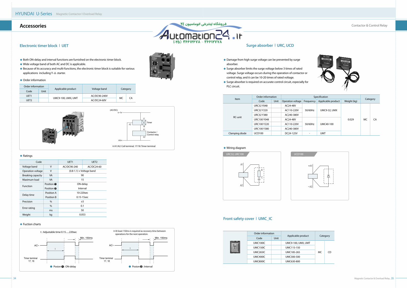
electronic timer block l Uet
◆ Both ON-delay and interval functions are furnished on the electronic timer block. ◆ Wide voltage band of both AC and DC is applicable. ◆ Because of its accuracy and multi-functions, the electronic timer block is suitable for various
applications including Y-△ starter.
◆ Order information
Code
Order information
UnitApplicable product Voltage band Category
UMC9-100, UMX, UMTAC/DC90-240V
AC/DC24-60VMC CA
UET1
UET2
◆ Fuction charts
u~/u-(AC/DC)
o/u+
Timer
Contactor /Control relay
※ A1/A2: Coil terminal, 17/18: Timer terminal
34
HYUNDAI U-Series Magnetic Contactor l Overload Relay
Accessories
surge absorber l URC, UCD
Front safety cover l UMC_IC
◆ Damage from high surge voltage can be prevented by surge absorber.
◆ Surge absorber limits the surge voltage below 3 times of rated voltage. Surge voltage occurs during the operation of contactor or control relay, and it can be 10-20 times of rated voltage.
◆ Surge absorber is required on accurate control circuit, especially for PLC circuit.
◆ Wiring diagram
URC32, URC100 UCD100
ItemOrder information Specification
CategoryCode Unit Operation voltage Frequency Applicable product Weight (kg)
RC-unit
URC32 Y048 AC24-48V
UMC9-32, UMX
0.029 MC CA
URC32 Y220 AC110-220V 50/60Hz
URC32 Y380 AC240-380V
URC100 Y048 AC24-48V
UMC40-100URC100 Y220 AC110-220V 50/60Hz
URC100 Y380 AC240-380V
Clamping diode UCD100 DC24-125V - UMT
Order informationApplicable product Category
Code Unit
UMC100IC UMC9-100, UMX, UMT
MC CD
UMC150IC UMC115-150
UMC265IC UMC185-265
UMC400IC UMC300-500
UMC800IC UMC630-800
AC~
Min. 150ms Min. 150ms
Timer terminal 17, 18
Timer terminal 17, 18
AC~
※ At least 150ms is required as recovery time between operations for the next operation.
t : Adjustable time 0.15......220sec
Posion : ON-delay Posion : Interval
◆ Ratings
Voltage band
Operation voltage
Breaking capacity
Maximum load
Function
Delay time
Precision
Error rating
Weight
Code UET1 UET2
V
V
VA
VA
Position
Position
Position A
Position B
%
%
ms
kg
AC/DC90-240 AC/DC24-60
(0.8-1.1) × Voltage band
90
15
ON-delay
Interval
10-220sec
0.15-15sec
±5
0.1
50
0.053

Magnetic Contactor & Overload Relay_37
Contactor & Control Relay
Order code Applicable product Composition Category
UMCHT100 UMC75-100
6EA MC CDUMCHT150 UMC115-150
UMCHT265 UMC185-265
UMCHT400 UMC300-400
Order code Applicable product Composition Category
UMCTIP9 UMC9
Moving contact: 3EA
Fixed contact: 6EAMC CD
UMCTIP12 UMC12
UMCTIP18 UMC18
UMCTIP25 UMC25
UMCTIP32 UMC32
UMCTIP40 UMC40
UMCTIP50 UMC50
UMCTIP65 UMC65
UMCTIP75 UMC75
UMCTIP85 UMC85
UMCTIP100 UMC100
UMCTIP115 UMC115
UMCTIP130 UMC130
UMCTIP150 UMC150
UMCTIP185 UMC185
UMCTIP225 UMC225
UMCTIP265 UMC265
UMCTIP300 UMC300
UMCTIP400 UMC400
UMCTIP500 UMC500
UMCTIP630 UMC630
UMCTIP800 UMC800
Moving contacts
Fixed contacts
36
HYUNDAI U-Series Magnetic Contactor l Overload Relay
spare Part
Coil l UMCOL
Arc chute l UMCHt
Main contact l UMCtIP
Order code Applicable product Composition Category
UMC12PC UMC9-12
Main terminal cover: 2EA
Coil terminal cover: 1EA
Auxiliary contact terminal
cover: 8EA (UMC115-800)
MC CD
UMC32PC UMC18-32
UMC65PC UMC40-65
UMC100PC UMC75-100
UMC150PC UMC115-150
UMC265PC UMC185-265
UMC400PC UMC300-500
UMC800PC UMC630-800
Mainterminal cover
Coilterminal cover
Auxiliary contactterminal cover
terminal protection cover l UMC_PC
◆ Order information
UMCOL
Code Description
Coil for contactor and control relayUMCOL
X220
Code Voltage (V) Current, frequency
AC, 50Hz
AC, 60Hz
DC
AC/DC
24-550
24-600
24-220
24-240
X
A
D
F
◆ Operation voltage
Model AC, 50Hz AC, 60Hz DC AC/DC Voltage band
UMCOL12
UMCOL32
UMCOL65
UMCOL100
UMCOL65
UMCOL100
24424880
100110120220230240380400415440
2448
100110120208220230240277380440460480
24486080
100110125200220250
UMCOL150
UMCOL265
24
48
220 440
AC: 24-26 DC: 24 AC: 44-52 DC: 48 AC: 100-240 DC: 110-220 AC: 380-450
UMCOL400
UMCOL800
220
440
AC: 100-240 DC: 110-220 AC: 380-450
(Unit: V)
12
Code Applicable product
UMC9-12, UMX, UMT
UMC18-32
UMC40-65
UMC75-100
UMC115-150
UMC185-265
UMC300-500
UMC630-800
12
32
65
100
150
265
400
800
◆ Standard order code
Code Applicable product Voltage Category
MC CC
UMCOL12 X220
UMCOL32 X220
UMCOL65 X220
UMCOL100 X220
UMCOL12 D110
UMCOL32 D110
UMCOL65 D110
UMCOL100 D110
UMCOL150 F220
UMCOL265 F220
UMCOL400 F220
UMCOL800 F220
UMC9-12, UMX
UMC18-32
UMC40-65
UMC75-100
UMC9-12, UMT
UMC18-32
UMC40-65
UMC75-100
UMC115-150
UMC185-265
UMC300-500
UMC630-800
AC220V, 50Hz
AC220V, 50Hz
AC220V, 50Hz
AC220V, 50Hz
DC110V
DC110V
DC110V
DC110V
AC/DC220V
AC/DC220V
AC/DC220V
AC/DC220V
※ Non-specified voltage can be available on request. For technical information of coil, please refer to page 42, 43.
※ For applicable voltage to each coil, please refer to below operation voltage table.

Magnetic Contactor & Overload Relay_39
Contactor & Control Relay
38
HYUNDAI U-Series Magnetic Contactor l Overload Relay
technical Information
The contactors can be selected according to rated themal current(Ith), rated operating current(le), making & breaking capacities, electrical & mechanical endurance, and utilization category.
◆ Utilization categories of IeC 60947
AC1
AC2
AC3
AC4
AC12
AC15
DC1
DC3
DC5
DC12
DC13
Non-inductive or slightly inductive loads, resistance furnaces
Slip-ring motors: starting, plugging
Squirrel cage motors: starting, switching off motors during running
Squirrel cage motors: plugging, inching
Resistive heating loads
Coil loads
Non-inductive or slightly inductive loads, resistance furnaces
Shunt motors: plugging, inching
Series motors: plugging, inching
Resistive heating loads
Coil loads
◆ Making and breaking capacities according to utilization categories
Making Making & breakingCategory
AC1
AC2
AC3
AC4
DC1
DC3
DC5
AC15
DC13
Number of operations
50
50
50
50
50
50
50
10
10
Cosø
0.8
0.65
0.45 (≤100A)
0.35 (>100A)
1.0
2.5
15
0.3
6P
Voltage
1.05Ue
1.05Ue
1.05Ue
1.05Ue
1.05Ue
1.05Ue
1.05Ue
1.1Ue
1.1Ue
Current
1.5Ie
4.0Ie
8.0Ie
10.0Ie
1.5Ie
4.0Ie
4.0Ie
10Ie
1.1Ie
Number of operations
-
-
50
50
-
-
-
-
-
Cosø
-
-
0.45 (≤100A)
0.35 (>100A)
-
-
-
-
-
Voltage
-
-
Ue
Ue
-
-
-
-
-
Current
-
-
10Ie
12Ie
-
-
-
-
-
Making & breakingCategory
AC1
AC2
AC3
AC4
DC1
DC3
DC5
AC15
DC13
Number of operations
6,000
6,000
6,000
6,000
6,000
6,000
6,000
6,000
6,000
On-time
0.05sec
0.05sec
0.05sec
0.05sec
0.05sec
0.05sec
0.05sec
0.05sec
0.05sec
Cosø
0.8
0.65
0.45 (Ie≤100A)
0.35 (Ie>100A)
1.0
2.0
7.5
0.3
6P
Voltage
1.05Ue
1.05Ue
1.05Ue
1.05Ue
1.05Ue
1.05Ue
1.05Ue
1.1Ue
1.1Ue
Current
1.0Ie
2.0Ie
2.0Ie
6.0Ie
1.0Ie
2.5Ie
2.5Ie
10Ie
1.1Ie
◆ Operating times according to utilization categories
Making BreakingCategory
AC1
AC2
AC3
AC4
DC1
DC3
DC5
Voltage
1Ue
1Ue
0.17Ue
1Ue
1Ue
1Ue
1Ue
Cosø
0.95
0.65
0.65 (Ie≤17A)
0.35 (Ie>17A)
1
2
7.5
Current
1Ie
2.5Ie
1Ie
6Ie
1Ie
2.5Ie
2.5Ie
Cosø
0.95
0.65
0.65 (Ie≤17A)
0.35 (Ie>17A)
1
2
7.5
Voltage
1Ue
1Ue
1Ue
1Ue
1Ue
1Ue
1Ue
Current
1Ie
2.5Ie
6Ie
6Ie
1Ie
2.5Ie
2.5Ie
◆ electrical characteristics according to utilization categories
※ Ie: Rated current Ue: Rated voltage
◆ selection of AC3 & AC4 contactors •When the frequency of operation is lower than the recommendation, motor output can be increased, but should not
exced the making and breaking capacities of the contactor. If thermal overload relay is used, the short-circuit protection should be caefully considered and the recommended fuse ratings should not be exceeded.
•The contactors can be chosen considering the electrical lifetime by means of the diagrams. •The electrical lifetime of the contactor fo for AC3, AC4 duty can be calculated using this formula.
L =1
P1/L1 + P2/L2 + … + Pn/Ln
L (electrical lifetime) = = 0.47 x 10⁶ 1
0.95/2.0 x 106 + 0.05/0.03 x 106
- On AC3 electrical lifetime curve, the lifetime of UMC100 is 2.0 x 10⁶
- On AC4 electrical lifetime curve, the lifetime of UMC100 is 0.03 x 10⁶
※ Example of UMC100
Motor: 80A full load current at AC440V, 480A starting current (6 times of rated current) AC3 use: 70A rated current with 95% coefficient AC4 use: 70A rated current (420A starting current) with 5% coefficient
※ Starting current must be less than 6 times of rated current.
10
5
3
2
1
0.5
0.3
0.22 3 5 10 20 30 50 100 200 300 500 1000
Millions of operating cycles
10
5
3
2
1
0.5
0.3
0.1
2 3 5 10 20 30 50 100 200 300 500 1000
Millions of operating cycles
0.05
0.03
0.02
0.01
0.005
0.2
97531
975
3
1
1 3 5 7 9
1 3 5 7 9
1 3 5 7 9
1 3 5 7 9
1 3 5 7 9
UMC9
UMC12
UMC18
UMC25
1 3 5 79
UMC32
UMC40
UMC50
UMC65 UMC75UMC85
UMC100
UMC115 UMC13
0 UMC150
UMC185 UMC22
5 UMC265
UMC300
UMC400
1 3 5 7 9
UMC9
UMC12
UMC18UMC25
UMC40
UMC50
UMC130
UMC150
UMC32
UMC85
UMC65UMC75
UMC225
UMC400
UMC185 UMC28
5 UMC300
1 3 5 7 9 1 3 5 7 91 3 5 79
1 3 5 7 9 1 3 5 7 9
97531
975
3
1
9753
1
UMC100 UMC11
5
AC3 electrical lifetime curve (380-440VAC)
10
5
3
2
1
0.5
0.3
0.22 3 5 10 20 30 50 100 200 300 500 1000
Millions of operating cycles
10
5
3
2
1
0.5
0.3
0.1
2 3 5 10 20 30 50 100 200 300 500 1000
Millions of operating cycles
0.05
0.03
0.02
0.01
0.005
0.2
97531
975
3
1
1 3 5 7 9
1 3 5 7 9
1 3 5 7 9
1 3 5 7 9
1 3 5 7 9
UMC9
UMC12
UMC18
UMC25
1 3 5 79
UMC32
UMC40
UMC50
UMC65 UMC75UMC85
UMC100
UMC115 UMC13
0 UMC150
UMC185 UMC22
5 UMC265
UMC300
UMC400
1 3 5 7 9
UMC9
UMC12
UMC18UMC25
UMC40
UMC50
UMC130
UMC150
UMC32
UMC85
UMC65UMC75
UMC225
UMC400
UMC185 UMC28
5 UMC300
1 3 5 7 9 1 3 5 7 91 3 5 79
1 3 5 7 9 1 3 5 7 9
97531
975
3
1
9753
1
UMC100 UMC11
5
AC4 electrical lifetime curve (380-440VAC)
•L : Electrical lifetime of contactor
•L1 : Electrical lifetime in AC3 duty
•L2 : Electrical lifetime in AC4 duty
•P1 : Coefficient of use in AC3 duty
•P2 : Coefficient of use in AC4 duty
•P1 + P2 + … + Pn = 1
Rated current(A)
Rated current(A)

Magnetic Contactor & Overload Relay_41
Contactor & Control Relay
40
HYUNDAI U-Series Magnetic Contactor l Overload Relay
technical Information
◆ Voltage, current & torque of Y-△ starting
◆ Contactor and thermal overload relay for normal Y-△ starter
Starting (Star-use contactor)
6Im
2Im
1.5T
0.5T
6Im
2Im
Im
Im Em
Contact voltageContact current Full load currentContact voltageFull load current TorqueStarting current Im
Operating (Delta-use contactor / C2)Starting method
Direct
Star-delta Em/ Im / Em/
※ Im: Delta wiring load current Em: Line-to line voltage T: Rated torque (assumed torque fluctuations)
Em/
※ - Above data are based on squirrel cage motor (AC3) and slip-ring motor (AC2). Data are subject to change according to motor classes and motor manufacturers. - Above data are based on less than 10 seconds motor starting time. Motor starting time must be considered when over 10 seconds motor starting time is applied. - Inrush current shall be considered when a capacitor is used. - Recommendable change-over time from Y-△ is between 30ms and 80ms. - 58% of motor full load current is recommended for UTH setting current. 1) FLC: Full load current.
※ C1: Main contactor C2: Delta contactor C3: Star contactor D1: Electronic timer block C4: Control relay
AC200-240V, 3ø, 60Hz
Motor capacity Main circult(C1)
△circult(C2)
Y circult(C3)
Thermaloverload
relaykW
5.5
7.5
11
15
18.5
22
30
37
45
55
75
90
110
132
160
250
300
HP
7.5
10
15
20
25
30
40
50
60
75
100
125
150
180
220
350
-
FLC1)
22
32
40
50
70
80
110
130
150
180
260
300
367
434
519
810
-
UMC25
UMC32
UMC40
UMC50
UMC50
UMC65
UMC100
UMC115
UMC130
UMC150
UMC185
UMC225
UMC300
UMC400
UMC400
UMC630
-
UMC25
UMC32
UMC40
UMC50
UMC50
UMC65
UMC100
UMC115
UMC130
UMC150
UMC185
UMC225
UMC300
UMC400
UMC400
UMC630
-
UMC18
UMC25
UMC32
UMC32
UMC40
UMC40
UMC50
UMC65
UMC65
UMC100
UMC115
UMC130
UMC150
UMC225
UMC225
UMC400
-
UTH32K
UTH32K
UTH65K
UTH65K
UTH65K
UTH65K
UTH100K
UTH150K
UTH150K
UTH150K
UTH265K
UTH265K
UTH400K
UTH400K
UTH400K
UTH800K
-
AC380-440V, 3ø, 60Hz
Motor capacity Main circult(C1)
△circult(C2)
Y circult(C3)
Thermaloverload
relaykW
5.5
7.5
11
15
18.5
22
30
37
45
55
75
90
110
132
160
250
300
HP
7.5
10
15
20
25
30
40
50
60
75
100
125
150
180
220
350
402
FLC1)
12
18
22
32
40
50
65
80
90
110
150
180
220
260
300
500
560
UMC25
UMC25
UMC25
UMC32
UMC40
UMC40
UMC50
UMC65
UMC65
UMC100
UMC115
UMC130
UMC150
UMC185
UMC225
UMC400
UMC400
UMC25
UMC25
UMC25
UMC32
UMC40
UMC40
UMC50
UMC65
UMC65
UMC100
UMC115
UMC130
UMC150
UMC185
UMC225
UMC400
UMC400
UMC25
UMC25
UMC25
UMC25
UMC25
UMC32
UMC40
UMC40
UMC40
UMC50
UMC65
UMC100
UMC115
UMC115
UMC130
UMC225
UMC300
UTH32K
UTH32K
UTH32K
UTH32K
UTH65K
UTH65K
UTH65K
UTH65K
UTH65K
UTH100K
UTH150K
UTH150K
UTH150K
UTH265K
UTH265K
UTH400K
UTH400K
Main circuit diagram Control circuit diagram
for UMC9-100 for UMC115-800
Operation Voltage Ratio Electrical lifetime UMC12
2.7
1.5
1.5
0.75
1.1
0.5
4
2.2
3.7
1.5
2.2
1.1
0.75
0.4
1
0.4
UMC9
2.2
1
1
0.5
0.75
0.3
2.7
1.5
1.5
0.75
1.1
0.5
0.75
0.2
0.75
0.2
UMC18
3.7
2.7
2.7
1.1
1.5
0.75
4
3.7
4
2.2
3.7
1.5
1.5
0.5
2.2
0.75
UMC25
4
3.7
3.7
1.5
2.5
1.1
7.5
7.5
7.5
3.7
5.5
2.2
2.2
0.75
3.7
1.5
UMC32
5.5
4.5
4.5
2.2
4.5
1.8
11
9
9
4.5
7.5
3.7
2.5
1.1
4.5
2.2
UMC40
7.5
5.5
5.5
3.7
4.5
2.7
15
11
11
5.5
11
3.7
3.7
1.5
4.5
2.2
UMC50
11
7.5
7.5
3.7
5.5
3.7
22
15
15
7.5
15
5.5
5.5
22
7.5
3.7
UMC65
15
11
11
5.5
7.5
4
30
22
22
11
15
7.5
7.5
3
11
5.5
UMC75
18.5
15
15
7.5
9
4
37
30
30
15
15
7.5
9
3.7
18.5
7.5
UMC85
19.0
15
15
7.5
11
5.5
37
30
30
15
22
11.0
9
3.7
18.5
7.5
UMC100
25
15
19
9
11
5.5
50
37
37
18.5
25
13
11
4.5
22.0
11.0
100,000
500,000
100,000
500,000
100,000
500,000
100,000
500,000
100,000
500,000
100,000
500,000
100,000
500,000
100,000
500,000
10%
50%
100%
10%
50%
100%
100%
AC220V
AC440V
AC220V
AC440V
Inching
Plugging
UMC130
30
22
22
9
15
7.5
60
45
45
22
30
15
15
5.5
30
15
UMC115
30
15
22
9
11
5.5
50
37
37
18.5
25
13
11
4.5
22
11
UMC150
37
25
30
11
19
9
75
55
55
30
45
22
19
7.5
37
19
UMC185
45
30
37
15
25
11
90
75
75
37
55
25
22
11
45
22
UMC225
55
37
45
19
30
15
110
90
90
37
60
30
25
13
45
25
UMC265
65
45
50
22
32
17
132
110
110
42
65
32
30
15
49
26
UMC300
75
50
55
25
37
22
150
125
132
50
75
37
37
18.5
55
30
UMC400
110
65
75
30
45
25
200
132
150
75
110
55
45
22
75
37
UMC500
132
70
80
32
50
30
250
140
167
80
120
63
50
25
90
40
UMC630
160
75
90
37
55
37
300
150
190
90
132
75
55
30
110
45
UMC800
200
132
150
45
75
45
400
190
220
110
160
90
75
37
150
100,000
500,000
100,000
500,000
100,000
500,000
100,000
500,000
100,000
500,000
100,000
500,000
100,000
500,000
100,000
500,000
10%
50%
100%
10%
50%
100%
AC220V
AC440V
AC220V
AC440V
Inching
Plugging
◆ Inching & plugging duty AC4 utilization category(Unit: kW)
Operation Voltage Ratio Electrical lifetime
※ - Ratio of inching operation (%) =
- The inching limit of making & breaking frequency is below the continous 10 operations based on 1 operation per 1 second.
Inching operationsStandard operations + Inching operations
x 100
100%
(Unit: kW)
3 3
3 3

Magnetic Contactor & Overload Relay_43
Contactor & Control Relay
42
HYUNDAI U-Series Magnetic Contactor l Overload Relay
technical Information
◆ Control coil voltage◆ Coil characteristics
Model UMC12
80
10/2.5
10
10
-
-
-
-
-
-
12-30
45-55
-
-
8-15
6-18
-
-
60
-
UMC18
80
10/2.5
10
10
-
-
-
-
-
-
12-30
45-55
-
-
8-15
6-18
-
-
60
-
UMC50
200
15/5
200
5
-
-
-
-
-
-
9-18
10-18
-
-
4-13
5-15
-
-
150
-
UMC65
200
15/5
200
5
-
-
-
-
-
-
9-18
10-18
-
-
4-13
5-15
-
-
150
-
UMC75
300
20/8
200
8
-
-
-
-
-
-
11-18
14-20
-
-
6-12
5-15
-
-
200
-
UMC85
300
20/8
200
8
-
-
-
-
-
-
11-18
14-20
-
-
6-12
5-15
-
-
200
-
VA
VA/W
W
W
VA
VA/W
VA
VA/W
W
W
ms
VA
Inrush
Sealed
Inrush
Sealed
Inrush
Sealed
Inrush
Sealed
Inrush
Sealed
AC
DC
AC
DC
AC
DC
AC
DC
AC operation coil(220V/60Hz)AC & DC
coil
AC/DC common coil
AC & DCcoil
AC/DCcommoncoil
AC & DCcoil
AC/DCcommoncoil
AC or DC coil
AC/DC common coil
AC operation coil(220V/60Hz)
AC operation coil(110V/60Hz)
DC operation coil
Closing(coil ON →contact ON)
Opening(coil OFF →contact OFF)
Min. capacity
DC operation coil
Prow
er c
onsu
mpt
ion
Ope
ratin
g tim
eCo
ntro
ltr
ansf
orm
er
UMC9
80
10/2.5
10
10
-
-
-
-
-
-
12-30
45-55
-
-
8-15
6-18
-
-
60
-
UMC25
80
10/2.5
10
10
-
-
-
-
-
-
12-30
45-55
-
-
8-15
6-18
-
-
60
-
UMC32
80
10/2.5
10
10
-
-
-
-
-
-
12-30
45-55
-
-
8-15
6-18
-
-
60
-
UMC40
200
15/5
200
5
-
-
-
-
-
-
9-18
10-18
-
-
4-13
5-15
-
-
150
-
Model AC, 50Hz AC, 60Hz DC Remark
UMC9
UMC12
UMC18
UMC25
UMC32
UMC40
UMC50
UMC65
UMC75
UMC85
UMC100
24424880
100110120220230240380400415440
2448
100110120208220230240277380440460480
24486080
100110125200220250
1) Rated current should be applied to the contactor coil.
2) Applicable voltage: 85-110%
3) Keep applying out bound applicable voltage could shorten
the coil lifetime.
4) If out of applicable voltage is applied to the coil, it could
cause short coil lifetime, coil burnt-out, and even fire.
(Unit: V)
AC/DC
Voltage bandRemark Model
UMC115UMC130UMC150UMC185UMC225UMC265
UMC300UMC400UMC500UMC630UMC800
24
48
220
440
220
440
AC: 24-26DC: 24 AC: 44-52DC: 48
AC: 100-240DC: 110-220
AC: 380-450
AC: 100-240DC: 110-220
AC: 380-450
1) Rated current should be applied to the contactor coil.
2) Applicable voltage: 85-110%
3) Keep applying out bound applicable voltage could shorten the coil
lifetime.
4) If out of applicable voltage is applied to the coil, it could cause short
coil lifetime, coil burnt-out, and even fire.
(Unit: V)
※ Non-specified voltage is available on request.
Model
VA
VA/W
W
W
VA
VA/W
VA
VA/W
W
W
ms
VA
Inrush
Sealed
Inrush
Sealed
Inrush
Sealed
Inrush
Sealed
Inrush
Sealed
AC
DC
AC
DC
AC
DC
AC
DC
AC operation coil(220V/60Hz)AC & DC
coil
AC/DC common coil
AC & DCcoil
AC/DCcommoncoil
AC & DCcoil
AC/DCcommoncoil
AC or DC coil
AC/DC common coil
AC operation coil(220V/60Hz)
AC operation coil(110V/60Hz)
DC operation coil
Closing(coil ON →contact ON)
Opening(coil OFF →contact OFF)
DC operation coil
UMC100
300
20/8
200
8
-
-
-
-
-
-
11-18
14-20
-
-
6-12
5-15
-
-
200
-
UMC115
-
-
-
-
290
7.4/3.8
180
3.3/2.1
193
2.3
-
-
40-80
70-80
-
-
18-25
15-20
-
200
UMC130
-
-
-
-
290
7.4/3.8
180
3.3/2.1
193
2.3
-
-
40-80
70-80
-
-
18-25
15-20
-
200
UMC150
-
-
-
-
290
7.4/3.8
180
3.3/2.1
193
2.3
-
-
40-80
70-80
-
-
18-25
15-20
-
200
UMC185
-
-
-
-
360
9.3/5.8
240
6.4/4.4
234
3.4
-
-
25-45
35-45
-
-
40-50
35-45
-
200
UMC225
-
-
-
-
360
9.3/5.8
240
6.4/4.4
234
3.4
-
-
25-45
35-45
-
-
40-50
35-45
-
200
UMC265
-
-
-
-
360
9.3/5.8
240
6.4/4.4
234
3.4
-
-
25-45
35-45
-
-
40-50
35-45
-
200
UMC300
-
-
-
-
380
9.3/5.8
250
6.4/4.4
234
3.4
-
-
25-40
35-45
-
-
35-50
35-45
-
200
UMC400
-
-
-
-
380
9.3/5.8
250
6.4/4.4
234
3.4
-
-
25-40
35-45
-
-
35-50
35-45
-
200
UMC500
-
-
-
-
380
9.3/5.8
250
6.4/4.4
234
3.4
-
-
25-40
35-45
-
-
35-50
35-45
-
200
UMC630
-
-
-
-
1,700
17.1/10.6
850
10.5/8
850
9.5
-
-
45-150
45-150
-
-
45-150
45-150
-
1,000
UMC800
-
-
-
-
1,700
17.1/10.6
850
10.5/8
850
9.5
-
-
45-150
45-150
-
-
45-150
45-150
-
1,000
※ The operating time of UMC115-400 is the average value of AC220V, 60Hz and DC110V.
Prow
er c
onsu
mpt
ion
Ope
ratin
g tim
eCo
ntro
ltr
ansf
orm
er
Min. capacity
Model

Magnetic Contactor & Overload Relay_45
Contactor & Control Relay
44
HYUNDAI U-Series Magnetic Contactor l Overload Relay
technical Information
Model Item AC DC
UMC40UMC50UMC65UMC75UMC85UMC100
Contactoronly
Contactor with side mounting auxiliary
contact block1)
(max.)2NO+1NC2NO+2NC
1L1
2T1
5L3
6T3
3L2
4T2
A1
A214
13
22
21
32
31
44
43
1L1
2T1
5L3
6T3
3L2
4T2
A1
A2
1L1
2T1
5L3
6T3
3L2
4T2
A1
A214
13
22
21
32
31
44
43
1L1
2T1
5L3
6T3
3L2
4T2
A1
A214
13
22
21
32
31
44
43
1L1
2T1
5L3
6T3
3L2
4T2
A1
A2
1L1
2T1
5L3
6T3
3L2
4T2
A1
A214
13
22
21
32
31
44
43
1L1
2T1
5L3
6T3
3L2
4T2
A1
A214
13
22
21
32
31
44
43
1L1
2T1
5L3
6T3
3L2
4T2
A1
A2
1L1
2T1
5L3
6T3
3L2
4T2
A1
A214
13
22
21
32
31
44
43
◆ Auxiliary contact characteristics
Rated insulation voltage
Rated thermal current [Ith]
Model UMC9-800
AC12(Resistiveloads)
Ratedcurrent[Ie]
AC15(Coil loads)
Hoistapplication1)
(NO contact only)
DC12(Resistiveloads)
DC13(Coil loads)
AC110V
AC220V
AC440V
AC690V
AC110V
AC220V
AC440V
AC690V
AC220V
DC24V
DC48V
DC110V
DC220V
DC24V
DC48V
DC110V
DC220V
AC750
16
10
8
6
2
6
6
3
2
10
5
3
2.5
1
3
2
1
0.6
V
A
A
A
A
A
A
IEC60947 UL & CSA
UMC9-800
Rated thermal current [Ith]
Ratedcurrent[Ie]
AC
DC
120V
240V
480V
600V
125V
250V
440V
600V
16
6
3
1.5
1.2
1.1
0.55
0.31
0.2
A
A
A
Model
◆ Contact arrangement
ItemModel AC, DC
UMC9UMC12
Contactoronly
Contactor with side mounting auxiliary
contact block1)
(max.)2NO+3NC3NO+2NC
1NO 1NC
UMC18UMC25UMC32
Contactoronly
Contactor with side mounting auxiliary
contact block1)
(max.)2NO+2NC
1L1
2T1
5L3
6T3
3L2
4T2
A1
A234
33 1L1
2T1
5L3
6T3
3L2
4T2
A1
A242
41
1L1
2T1
5L3
6T3
3L2
4T2
A1
A234
33 1L1
2T1
5L3
6T3
3L2
4T2 42
41
14
13
22
21
32
31
44
43 A1
A214
13
22
21
32
31
44
43
1L1
2T1
5L3
6T3
3L2
4T2
A1
A234
33 1L1
2T1
5L3
6T3
3L2
4T2
A1
A242
41
1L1
2T1
5L3
6T3
3L2
4T2
A1
A234
33 1L1
2T1
5L3
6T3
3L2
4T2 42
41
14
13
22
21
32
31
44
43 A1
A214
13
22
21
32
31
44
43
1L1
2T1
5L3
6T3
3L2
4T2
A1
A2
1L1
2T1
5L3
6T3
3L2
4T2
A1
A214
13
22
21
32
31
44
43
1) Hoist application is available for UMC9-100.
Contactor and auxiliary block
Model AC/DC
UMC115UMC130UMC150UMC185UMC225UMC265UMC300UMC400UMC500UMC630UMC800
Contactoronly
Contactor with side mounting auxiliary
contact block1)
(max.)
2NO+2NC
4NO+4NC
1L1
2T1
5L3
6T3
3L2
4T2
A1
A214
13
22
21
32
31
44
43
1L1
2T1
5L3
6T3
3L2
4T2
A1
A214
13
22
21
32
31
44
43
54
53
62
61
72
71
84
83
1L1
2T1
5L3
6T3
3L2
4T2
A1
A214
13
22
21
32
31
44
43
1L1
2T1
5L3
6T3
3L2
4T2
A1
A214
13
22
21
32
31
44
43
54
53
62
61
72
71
84
83
Item
A1
A244
43
34
33
24
23
14
13
A1
A244
43
34
33
22
21
14
13
A1
A244
43
32
31
22
21
14
13
A1
A242
41
32
31
22
21
12
11
A1
A242
41
32
31
24
23
12
11
Control relay
Model AC, DC
UMX04UMT04
UMX13UMT13
UMX22UMT22
UMX31UMT31
UMX40UMT40
※1) For applicable auxiliary contact block, please refer to page 30, 31.
※1) For applicable auxiliary contact block, please refer to page 30, 31.
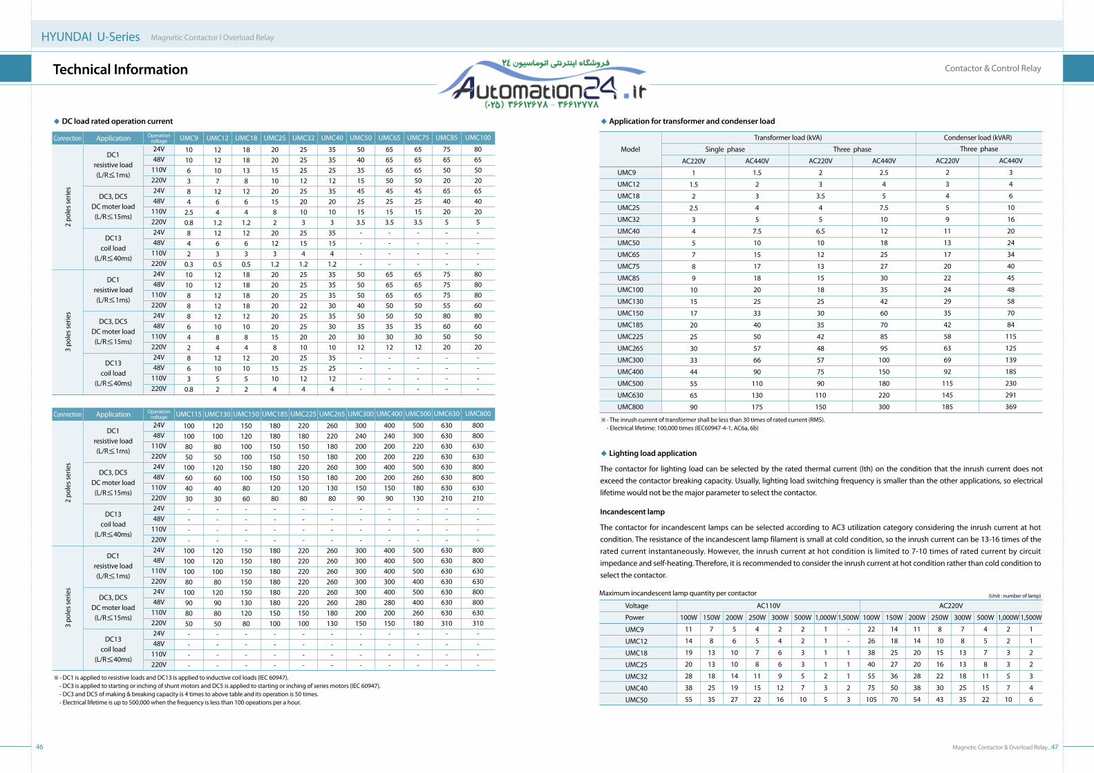
Magnetic Contactor & Overload Relay_47
Contactor & Control Relay
46
HYUNDAI U-Series Magnetic Contactor l Overload Relay
technical Information
Connection Application Operation voltage UMC12
1212107
1264
1.21263
0.512121212121084
121052
UMC9
10106384
2.50.8842
0.31010888642863
0.8
UMC18
1818138
1264
1.21263
0.518181818121084
121052
UMC25
20201510201582
20123
1.2202020202020158
2015104
UMC32
252525122520103
25154
1.225252522252520102525124
UMC40
353525123520103
35154
1.235353530353020103525124
UMC50
504035154525153.5
----
5050504050353012----
UMC65
656565504525153.5
----
6565655050353012----
UMC75
656565504525153.5
----
6565655050353012----
UMC85
756550206540205----
7575755580605020----
UMC100
806550206540205----
8080806080605020----
24V48V
110V220V24V48V
110V220V24V48V
110V220V24V48V
110V220V24V48V
110V220V24V48V
110V220V
DC1resistive load(L/R≤1ms)
DC3, DC5DC moter load(L/R≤15ms)
DC13coil load
(L/R≤40ms)
DC1resistive load(L/R≤1ms)
DC3, DC5DC moter load(L/R≤15ms)
DC13coil load
(L/R≤40ms)
Connection Application Operation voltage UMC130
1201008050
120604030----
12012010080
120908050----
UMC115
1001008050
100604030----
10010010080
100908050----
UMC150
1501201001001501008060----
15015015015015013012080----
UMC185
18018015015018015012080----
180180180180180180150100
----
UMC225
22018015015022015012080----
220220220220220220150100
----
UMC265
26022018018026018013080----
260260260260260260180130
----
UMC300
30024020020030020015090----
300300300300300280200150
----
UMC400
40024020020040020015090----
400400400300400280200150
----
UMC500
500300220220500260180130
----
500500500400500400260180
----
UMC630
630630630630630630630210
----
630630630630630630630310
----
UMC800
800800630630800800630210
----
800800630630800800630310
----
24V48V
110V220V24V48V
110V220V24V48V
110V220V24V48V
110V220V24V48V
110V220V24V48V
110V220V
DC1resistive load(L/R≤1ms)
DC3, DC5DC moter load(L/R≤15ms)
DC13coil load
(L/R≤40ms)
DC1resistive load(L/R≤1ms)
DC3, DC5DC moter load(L/R≤15ms)
DC13coil load
(L/R≤40ms)
◆ DC load rated operation current
※ - DС1 is applied to resistive loads and DC13 is applied to inductive coil loads (IEC 60947). - DC3 is applied to starting or inching of shunt motors and DC5 is applied to starting or inching of series motors (IEC 60947). - DC3 and DC5 of making & breaking capacity is 4 times to above table and its operation is 50 times. - Electrical lifetime is up to 500,000 when the frequency is less than 100 opeations per a hour.
Transformer load (kVA)
Single phase Three phase
Condenser load (kVAR)
Model
AC220V
1
1.5
2
2.5
3
4
5
7
8
9
10
15
17
20
25
30
33
44
55
65
90
UMC9
UMC12
UMC18
UMC25
UMC32
UMC40
UMC50
UMC65
UMC75
UMC85
UMC100
UMC130
UMC150
UMC185
UMC225
UMC265
UMC300
UMC400
UMC500
UMC630
UMC800
AC440V
1.5
2
3
4
5
7.5
10
15
17
18
20
25
33
40
50
57
66
90
110
130
175
AC220V
2
3
3.5
4
5
6.5
10
12
13
15
18
25
30
35
42
48
57
75
90
110
150
AC440V
2.5
4
5
7.5
10
12
18
25
27
30
35
42
60
70
85
95
100
150
180
220
300
AC220V
2
3
4
5
9
11
13
17
20
22
24
29
35
42
58
63
69
92
115
145
185
AC440V
3
4
6
10
16
20
24
34
40
45
48
58
70
84
115
125
139
185
230
291
369
Three phase
※ - The inrush current of transformer shall be less than 30 times of rated current (RMS). - Electrical lifetime: 100,000 times (IEC60947-4-1, AC6a, 6b)
The contactor for lighting load can be selected by the rated thermal current (Ith) on the condition that the inrush current does not exceed the contactor breaking capacity. Usually, lighting load switching frequency is smaller than the other applications, so electrical lifetime would not be the major parameter to select the contactor.
Incandescent lamp
The contactor for incandescent lamps can be selected according to AC3 utilization category considering the inrush current at hot condition. The resistance of the incandescent lamp filament is small at cold condition, so the inrush current can be 13-16 times of the rated current instantaneously. However, the inrush current at hot condition is limited to 7-10 times of rated current by circuit impedance and self-heating. Therefore, it is recommended to consider the inrush current at hot condition rather than cold condition to select the contactor.
1,500W
1
1
2
2
3
4
6
AC220VAC110V
1,000W
2
2
3
3
5
7
10
500W
4
5
7
8
11
15
22
300W
7
8
13
13
18
25
35
250W
8
10
15
16
22
30
43
200W
11
14
20
20
28
38
54
150W
14
18
25
27
36
50
70
100W
22
26
38
40
55
75
105
1,500W
-
-
1
1
1
2
3
1,000W
1
1
1
1
2
3
5
500W
2
2
3
3
5
7
10
300W
2
4
6
6
9
12
16
250W
4
5
7
8
11
15
22
200W
5
6
10
10
14
19
27
150W
7
8
13
13
18
25
35
100W
11
14
19
20
28
38
55
UMC9
UMC12
UMC18
UMC25
UMC32
UMC40
UMC50
Voltage
Power
Maximum incandescent lamp quantity per contactor
◆ Application for transformer and condenser load
◆ Lighting load application
2 po
les s
erie
s2
pole
s ser
ies
3 po
les s
erie
s3
pole
s ser
ies
(Unit : number of lamp)

48
HYUNDAI U-Series Magnetic Contactor l Overload Relay
technical Information
◆ Applicable cable size & tightening torque
Main terminal
Terminal screw Applicable cable size (mm2) Tightening torque (kgf.cm)Model
UMC9
UMC12
UMC18
UMC25
UMC32
UMC40
UMC50
UMC65
UMC75
UMC85
UMC100
UMC115
UMC130
UMC150
UMC185
UMC225
UMC265
UMC300
UMC400
UMC500
UMC630
UMC800
M3.5
M3.5
M4
M4
M4
M6
M6
M6
M8
M8
M8
M8
M8
M8
M10
M10
M10
M12
M12
M12
M16
M16
1.25-5.5
1.25-5.5
1.25-14
1.25-14
1.25-14
2-22
2-22
2-22
2-38
2-38
2-38
2-60
2-60
2-60
2-150
2-150
2-150
2-240
2-240
2-240
80-325
80-325
12
12
26
26
26
40
40
40
60
60
60
60
60
60
100
100
100
140
140
140
140
140
Coil terminal
Terminal screw Applicable cable size (mm2) Tightening torque (kgf.cm)Model
UMC9-100
UMC115-800M3.5 1.25-2 12
thermal Overload Relay
+ + + + + + + + + + + + + + + + + + + + + + + ++ + + + + + + + + + + + + + + + + + + + + + + ++ + + + + + + + + + + + + + + + + + + + + + + ++ + + + + + + + + + + + + + + + + + + + + + + ++ + + + + + + + + + + + + + + + + + + + + + + ++ + + + + + + + + + + + + + + + + + + + + + + ++ + + + + + + + + + + + + + + + + + + + + + + ++ + + + + + + + + + + + + + + + + + + + + + + +

Magnetic Contactor & Overload Relay_51
Thermal Overload Relay
50
HYUNDAI U-Series Magnetic Contactor l Overload Relay
specifications & Order Information
Model UTH100UTH65UTH32UTH12
UMC75
UMC85
UMC100
Setting сurrent (A)
UMC40
UMC50
UMC65
Setting сurrent (A)
UMC18
UMC25
UMC32
Setting сurrent (A) Setting сurrent (A)
UMC9
UMC12
Min.
17
22
28
34
45
52
59
70
Mid.
21
27
34
42
55
63
72
85
Max.
25
32
40
50
65
75
85
100
Min.
7
8
12
15
17
22
28
34
45
Mid.
8.5
10
15
18.5
21
27
34
42
55
Max.
10
12
18
22
25
32
40
50
65
Min.
0.12
0.18
0.25
0.34
0.5
0.6
0.8
1.1
1.5
2
2.8
3
4
5.6
6
8
12
15
17
22
Mid.
0.15
0.22
0.3
0.42
0.6
0.75
1
1.35
1.8
2.5
3.5
4
5
6.8
7.5
10
15
18.5
21
27
Max.
0.18
0.26
0.35
0.5
0.7
0.9
1.2
1.6
2.1
3
4.2
5
6
8
9
12
18
22
25
32
Min.
0.12
0.18
0.25
0.34
0.5
0.6
0.8
1.1
1.5
2
2.8
3
4
5.6
6
8
Mid.
0.15
0.22
0.3
0.42
0.6
0.75
1
1.35
1.8
2.5
3.5
4
5
6.8
7.5
10
Max.
0.18
0.26
0.35
0.5
0.7
0.9
1.2
1.6
2.1
3
4.2
5
6
8
9
12
Applicable contactor
Nominal current
0.18
0.26
0.35
0.5
0.7
0.9
1.2
1.6
2.1
3
4.2
5
6
8
9
10
12
18
22
25
32
40
50
65
75
85
100
K-type
H-type
Auxiliary contact
Reset
Phase loss protection (Differential trip)
Applicable cable Main terminal
(mm2) Aux. terminal
Dimensions (mm)
Weight (kg, K-type)
◆ Order information
UTH 100
Code
UTH
Series
UTH
Code Applicable contactor
12
32
65
100
UMC9-12
UMC18-32
UMC40-65
UMC75-100
S
Code Terminalaccessory
S Safety cover
K
Code Element
K
H
3
2
A0100
Code Setting current (A) Code Setting
current (A)
A0P18
A0P26
A0P35
A0P50
A0P70
A0P90
A1P20
A1P60
A2P10
A0003
A4P20
A0005
A0006
A0008
A0009
A0010
A0012
A0018
A0022
A0025
A0032
A0040
A0050
A0065
A0075
A0085
A0100
0.12-0.18
0.18-0.26
0.25-0.35
0.34-0.5
0.5-0.7
0.6-0.9
0.8-1.2
1.1-1.6
1.5-2.1
2-3
2.8-4.2
3-5
4-6
5.6-8
6-9
7-10
8-12
12-18
15-22
17-25
22-32
28-40
34-50
45-65
52-75
59-85
70-100
3 element
2 element
1NO+1NC
Manual & Automatic
K-type only
1-2.5
1-2.5
45 × 79 × 76
0.125
2-10
45 × 81 × 91
0.165
2-25
55 × 94 × 105
0.302
6-38
70 x 108 x 123
0.545
◆ DIN-rail adaptor
Model Code Mounting method Category
MC CB
Weight (kg)
Screw & DIN-rail
0.060
0.079
0.126
0.222
UTHMB12
UTHMB32
UTHMB65
UTHMB100
UTHMB
UtH12-100 l 0.12-100A
Phase protection
※ UTH makes trip within 2 minutes on 150% overload at hot condition, so the protection class of UTH is 10A.
◆ Standard order code and unit
Model Code Setting current (A) Unit
UTH12
UTH65
UTH12K A0P18SUTH12K A0P26SUTH12K A0P35SUTH12K A0P50SUTH12K A0P70SUTH12K A0P90SUTH12K A1P20SUTH12K A1P60SUTH12K A2P10SUTH12K A0003SUTH12K A4P20SUTH12K A0005SUTH12K A0006SUTH12K A0008SUTH12K A0009SUTH12K A0012SUTH65K A0010SUTH65K A0012SUTH65K A0018SUTH65K A0022SUTH65K A0025SUTH65K A0032SUTH65K A0040SUTH65K A0050SUTH65K A0065S
0.12-0.180.18-0.260.25-0.350.34-0.50.5-0.70.6-0.90.8-1.21.1-1.61.5-2.1
2-32.8-4.2
3-54-6
5.6-86-9
8-127-108-12
12-1815-2217-2522-3228-4034-5045-65
Model Code Setting current (A) Unit Category
MC CF
UTH32
UTH100
UTH32K A0P18SUTH32K A0P26SUTH32K A0P35SUTH32K A0P50SUTH32K A0P70SUTH32K A0P90SUTH32K A1P20SUTH32K A1P60SUTH32K A2P10SUTH32K A0003SUTH32K A4P20SUTH32K A0005SUTH32K A0006SUTH32K A0008SUTH32K A0009SUTH32K A0012SUTH32K A0018SUTH32K A0022SUTH32K A0025SUTH32K A0032S
UTH100K A0025SUTH100K A0032SUTH100K A0040SUTH100K A0050SUTH100K A0065SUTH100K A0075SUTH100K A0085SUTH100K A0100S
0.12-0.180.18-0.260.25-0.350.34-0.50.5-0.70.6-0.90.8-1.21.1-1.61.5-2.1
2-32.8-4.2
3-54-6
5.6-86-9
8-1212-1815-2217-2522-3217-2522-3228-4034-5045-6552-7559-85
70-100
Width ×
Height ×
Depth
44444444444444444444444444444444282828282828282828
40404040404040404040404040404040404040401010101010101010

Magnetic Contactor & Overload Relay_53
Thermal Overload Relay
52
HYUNDAI U-Series Magnetic Contactor l Overload Relay
specifications & Order Information
◆ Order information
◆ Standard order code and unit
Model Code Setting current (A) Unit
MC CF
Category
UTH150
UTH265
UTH400
UTH800
UTH150K A0080S
UTH150K A0115S
UTH150K A0130S
UTH150K A0150S
UTH265K A0080S
UTH265K A0115S
UTH265K A0130S
UTH265K A0150S
UTH265K A0185S
UTH265K A0225S
UTH265K A0265S
UTH400K A0150S
UTH400K A0185S
UTH400K A0225S
UTH400K A0265S
UTH400K A0300S
UTH400K A0400S
UTH800K A0500S
UTH800K A0630S
UTH800K A0800S
48-80
69-115
78-130
90-150
48-80
69-115
78-130
90-150
111-185
135-225
159-265
90-150
111-185
135-225
159-265
180-300
240-400
300-500
378-630
480-800
K
Code Element
K
H
3
2
A0800
Code Setting current(A)
A0080
A0115
A0130
A0150
A0185
A0225
A0265
A0300
A0400
A0500
A0630
A0800
48-80
69-115
78-130
90-150
111-185
135-225
159-265
180-300
240-400
300-500
378-630
480-800
UtH150-800 l 48-800A (Ct operated type)S
Code Terminal accessory
S Safety cover
Model
Applicable contactor
Nominal current
80 (CT 80:5)
115 (CT 115:5)
130 (CT 130:5)
150 (CT 150:5)
185 (CT 185:5)
225 (CT 225:5)
265 (CT 265:5)
300 (CT 300:5)
400 (CT 400:5)
500 (CT 500:5)
630 (CT 630:5)
800 (CT 800:5)
K-type
H-type
Auxiliary contact
Reset
Phase loss protection (Differential trip)
Applicable cable Main terminal
(mm2) Aux. terminal
Dimensions (mm)
Weight (kg, K-type)
UTH150 UTH265 UTH400 UTH800
UMC115
UMC130
UMC150
Setting current (A)
UMC185
UMC225
UMC265
Setting current (A)
UMC300
UMC400
Setting current (A)
UMC500
UMC630
UMC800
Setting current (A)
Min.
48
69
78
90
Mid.
64
92
104
120
Max.
80
115
130
150
Min.
48
69
78
90
111
135
159
Mid.
64
92
104
120
148
180
212
Max.
80
115
130
150
185
225
265
Min.
90
111
135
159
180
240
Mid.
120
148
180
212
240
320
Max.
150
185
225
265
300
400
Min.
300
378
480
Mid.
400
504
640
Max.
500
630
800
3 element
2 element
1NO+1NC
Manual & Automatic
K-type only
1-2.5
-
180 × 159 × 187
1.65
-
180 × 185 × 185
1.85
-
180 × 205 × 185
1.94
-
245 × 223 × 197
5.70
Phase protection
※ UTH makes trip within 2minutes on 150% overload at hot condition, so the protection class of UTH is 10A.
UTH 800
Code
UTH
Series
UTH
Code Applicable contactor
150
265
400
800
UMC115-150
UMC185-265
UMC300-500
UMC630-800
Width ×
Height ×
Depth
3
3
3
3
3
3
3
3
3
3
3
3
3
3
3
3
3
1
1
1
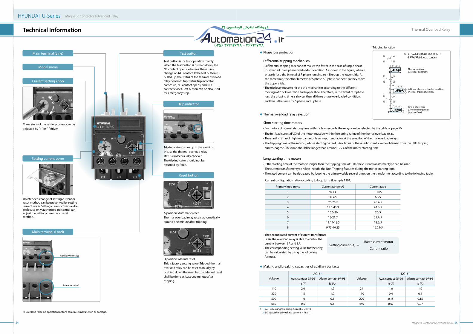
Magnetic Contactor & Overload Relay_55
Thermal Overload Relay
54
HYUNDAI U-Series Magnetic Contactor l Overload Relay
technical Information
Three steps of the setting current can be adjusted by "+" or "-" driver.
Trip indicator comes up in the event of trip, so the thermal overload relay status can be visually checked. The trip indicator should not be returned by force.
Unintended change of setting current or reset method can be prevented by setting current cover. Setting current cover can be sealed, so only authorized personnel can adjust the setting current and reset method.
Test button is for test operation mainly. When the test button is pushed down, the NC contact opens; whereas, there is no change on NO contact. If the test button is pulled up, the status of the thermal overload relay becomes trip status; trip indicator comes up, NC contact opens, and NO contact closes. Test button can be also used for emergency stop.
A position: Automatic resetThermal overload relay resets automatically around one minute after tripping.
H position: Manual reset This is factory setting value. Tripped thermal overload relay can be reset manually by pushing down the reset button. Manual reset shall be done at least one minute after tripping.
◆ Thernal overload relay selection
Short starting time motors
•Formotorsofnormalstartingtimewithinafewseconds,therelayscanbeselectedbythetableofpage56.
•Thefullloadcurent(FLC)ofthemotormustbewithinthesettingrangeofthethemaloverloadrelay. •Thestartingtimeofhigh-inertiamotorisanimportantfactorattheselectionofthermaloverloadrelays. • The tripping time of the motors, whose starting current is 6-7 times of the rated current, can be obtained from the UTH tripping
curves, page56. This time should be longer than around 125% of the motor starting time.
Long starting time motors • If the starting time of the motor is longer than the tripping time of UTH, the current transformer type can be used. • The current transformer type relays include the Non-Tripping features during the motor starting time. • The rated current can be decreased by looping the primary cable several times on the transformer according to the following table.
Current configuration ratio according to loop turns (Example 130A)
Primary loop turns Current range (A) Current ratio
1
2
3
4
5
6
7
8
78-130
39-65
26-26.7
19.5-43.3
15.6-26
13-21.7
11.14-18.5
9.75-16.25
130/5
65/5
26.7/5
43.3/5
26/5
21.7/5
18.5/5
16.25/5
◆ Making and breaking capacities of auxiliary contacts
※ 1) AC15: Making/breaking current = le x 10 2) DC13: Making/breaking current = le x 1.1
VoltageAC151)
Voltage
DC132)
Aux. contact 95-96
Ie (A)
Alarm contact 97-98
Ie (A)
Aux. contact 95-96
Ie (A)
Alarm contact 97-98
Ie (A)
110
220
500
660
2.0
1.5
1.0
0.5
1.2
1.0
0.5
0.3
24
110
220
440
1.0
0.4
0.15
0.07
1.0
0.4
0.15
0.07
Auxiliary contact
Main terminal
Tripping function
※ - L1/L2/L3: 3phase line (R, S, T) - 95/96/97/98: Aux. contact
Normal position(Untripped position)
All three phase overloaded condition(Normal tripping function)
Single phase loss(Differential tripping)(R phase fixed)
Setting current cover
Main terminal (Load)
Test button
Trip indicator
Reset button
Main terminal (Line)
Current setting knob
Model name
※ Excessive force on operation buttons can cause malfunction or damage.
Setting current (A) =Rated current motor
Current ratio
• The second rated current of current transformer is 5A, the overload relay is able to control the current between 3A and 5A.• The corresponding setting value for the relay
can be calculated by using the following formula.
◆ Phase loss protection Differential tripping mechanism •Differentialtrippingmechanismmakestripfasterinthecaseofsinglephase
loss than all three phase overloaded condition. As shown in the figure, when R phase is loss, the bimetal of R phase remains, so it fixes up the lower slide. At the same time, the other bimetals of S phase & T phase are bent, so they move the upper slide.
•Thetriplevermovetohitthetripmechanismaccordingtothedifferentmoving ratio of lower slide and upper slide. Therefore, in the event of R phase loss, the tripping time is shorter than all three phase overloaded condition, and this is the same for S phase and T phase.

56
HYUNDAI U-Series Magnetic Contactor l Overload Relay
technical Information
● Dimensions● Installation● Precautions
+ + + + + + + + + + + + + + + + + + + + + + + ++ + + + + + + + + + + + + + + + + + + + + + + ++ + + + + + + + + + + + + + + + + + + + + + + ++ + + + + + + + + + + + + + + + + + + + + + + ++ + + + + + + + + + + + + + + + + + + + + + + ++ + + + + + + + + + + + + + + + + + + + + + + ++ + + + + + + + + + + + + + + + + + + + + + + ++ + + + + + + + + + + + + + + + + + + + + + + +
UTH12K UTH32K UTH65K
UTH100K UTH150-400K, UTH800K (500A) UTH800K (630, 800A)
0.30.40.50.60.8
1
2
34568
10
20
3040
60
2
34568
10
20
3040
60
1 2 3 4 5 6 7 8 9 10 12
Sec
ond
Min
ute
Trip
ping
tim
e
Trip
ping
tim
e
Trip
ping
tim
e
Trip
ping
tim
e
Trip
ping
tim
e
Trip
ping
tim
e
2 h
1.2 1.50.30.40.50.60.8
1
2
34568
10
20
3040
60
2
34568
10
20
3040
60
1 2 3 4 5 6 7 8 9 10 12
Sec
ond
Min
ute
2 h
1.2 1.5
0.30.40.50.60.8
1
2
34568
10
20
3040
60
2
34568
10
20
3040
60
1 2 3 4 5 6 7 8 9 10 12
Sec
ond
Min
ute
2 h
1.2 1.5
0.30.40.50.60.8
1
2
34568
10
20
3040
60
2
34568
10
20
3040
60
1 2 3 4 5 6 7 8 9 10 12S
econ
dM
inut
e
2 h
1.2 1.5
0.30.40.50.60.8
1
2
34568
10
20
3040
60
2
34568
10
20
3040
60
1 2 3 4 5 6 7 8 9 10 12
Sec
ond
Min
ute
2 h
1.2 1.50.30.40.50.60.8
1
2
34568
10
20
3040
60
2
34568
10
20
3040
60
1 2 3 4 5 6 7 8 9 10 12
Sec
ond
Min
ute
2 h
1.2 1.5
Multiple of current setting X → ln[A] Multiple of current setting X → ln[A] Multiple of current setting X → ln[A]
Multiple of current setting X → ln[A] Multiple of current setting X → ln[A] Multiple of current setting X → ln[A]
◆ Tripping curve
•Trippingcurveof3phaseoverloadconditionshowstheaveragetrippingtimebasedonthecoldstartingat+20℃ ambient temperature. Tripping time of hot starting is 20-40% of cold starting.
•Averagetrippingtimeofsinglephaseoverloadis40-60%ofthreephaseoverload.

Magnetic Contactor & Overload Relay_5958
HYUNDAI U-Series Magnetic Contactor l Overload Relay
Dimensions
Contactor(Unit: mm)
146.
0
155.
0
16.5
M8 bolt
95.9
145.9
103.065.0
146.
0
10.2
90.0
120.
013
0.0
6.2
UMC115 / UMC130 / UMC150
(Unit: mm)
DC: 112.0
31.2
31.844.064.0
40.0
62.6
75.0
57.0
7.0AC: 80.0A
50.0
68.0
30.0
35.0
M3.5 (Aux. terminal)
M3.5 (Coil terminal)
M3.5 (Main terminal)
UMC9 / UMC12
UABULBUET
Accessory A (mm)35
42.539
26.4
41.2
96.0
123.
0
140.
0
45.0
70.0
94.0
M3.5 (Coil terminal)
M8 (Main terminal)
M3.5 (AUX. terminal)
A 127.58
55.0
60.0
130.
0
77.1
UMC75 / UMC85 / UMC100
UABULBUET
Accessory A (mm)35
42.539
29.0
45.0
65.0
52.0
78.6
83.0
60.424.4
7.0
35.0
60.0
75.5
DC: 126.9AC: 93.9A
M3.5 (Aux. terminal)
M4 (Main terminal)
M3.5 (Coil terminal)
UMC18 / UMC25 / UMC32
UABULBUET
Accessory A (mm)35
42.539
24.0
55.075.0
69.6
35.0
99.0
106.
4
43.047.0
95.0
72.4
8.0
110.8A
M3.5 (Aux. terminal)
M6 (Main terminal)
M3.5 (Coil terminal)UMC40 / UMC50 / UMC65
UABULBUET
Accessory A (mm)35
42.539
※ Dimensions may be revised without notice.
116.0
12.0174.2
91.0
138.0
25.0
164.
018
9.0
204.
0
M10 bolt
6.0
120.0
161.
017
1.0
19.0
UMC185 / UMC225 / UMC265
※ Dimensions may be revised without notice.

Magnetic Contactor & Overload Relay_6160
HYUNDAI U-Series Magnetic Contactor l Overload Relay
Dimensions
Control relay
203.0
18.5109.0163.0
243.
0
201.
0
30.0
133.2M12 bolt
145.0
221.
0
225.
0
8.6
UMC300 / UMC400 / UMC500
159.0276.0
274.
0
40.0
300.
0
M16 bolt 25.0157.2
258.2250.0
270.
0
10.8
UMC630 / UMC800
(Unit: mm)Contactor with thermal overload relay
44.0
129.
6
40.0
80.057.0
77.962.2
24.8
35.029.8
68.0
50.0
UMC9 / UMC12 + UTH12
45.065.0
52.0
141.
3
15.440.1
60.493.9
35.0
75.5
60.0
34.275.6
91.3
UMC18 / UMC25 / UMC32 + UTH32
55.075.0
69.6
174.
9
29.253.9
66.4109.8
41.047.0
92.0
100.
0
40.892.7
108.4
UMC40 / UMC50 / UMC65 + UTH65
(Unit: mm)
※ Dimensions may be revised without notice.
UMT: 112.0
31.2
31.844.064.0
40.0
62.6
75.0
57.0
7.0UMX: 80.0A
50.0
68.0
30.0
35.0
M3.5 (Aux. terminal)
M3.5 (Coil terminal)
M3.5 (Main terminal)
UMX / UMT
※ Dimensions may be revised without notice.
UABULBUET
Accessory A (mm)35
42.539
Contactor
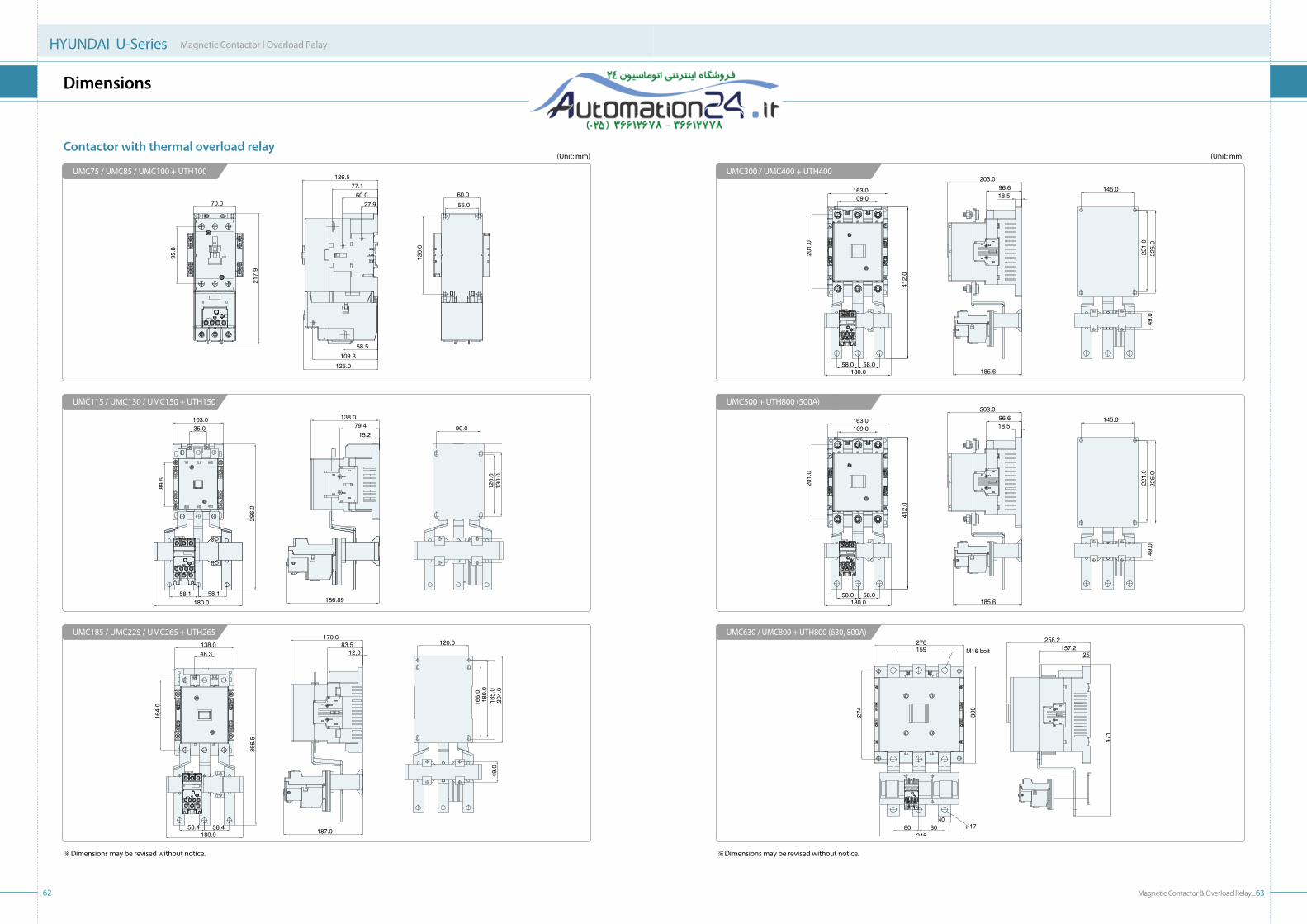
Magnetic Contactor & Overload Relay_6362
HYUNDAI U-Series Magnetic Contactor l Overload Relay
Dimensions
Contactor with thermal overload relay(Unit: mm) (Unit: mm)
UMC75 / UMC85 / UMC100 + UTH100 UMC300 / UMC400 + UTH400
UMC115 / UMC130 / UMC150 + UTH150 UMC500 + UTH800 (500A)
UMC185 / UMC225 / UMC265 + UTH265 UMC630 / UMC800 + UTH800 (630, 800A)
※ Dimensions may be revised without notice. ※ Dimensions may be revised without notice.
70.0
95.8
217.
9
27.960.0
77.1126.5
58.5
109.3
125.0
55.0
60.0
130.
0103.035.0
89.5
296.
0
186.89
138.0
15.279.4
180.058.1 58.1
153.
0
90.0
130.
012
0.0
49.0
138.048.3
164.
0
366.
5
12.083.5
170.0
187.058.4 58.4
180.0
120.0
204.
018
5.0
180.
0
49.0
166.
0
109.0163.0
201.
0
203.096.618.5
145.0
225.
022
1.0
49.0
412.
0
58.0 58.0180.0 185.6
109.0163.0
201.
0
203.096.618.5
145.0
225.
022
1.0
49.0
412.
0
58.0 58.0180.0 185.6
159276
274
300
24580 80 Ø17
40
M16 bolt25
157.2258.2
471

Magnetic Contactor & Overload Relay_6564
HYUNDAI U-Series Magnetic Contactor l Overload Relay
Dimensions
thermal overload relay60
.4
45.0
10.6 10.5 10.1
12.7
54.4
78.4
10.6 10.6 10.610.0 10.0 10.0
2.1
54.4
7.3 42.3
27.9
22.5
59.9 75
.6
M3.5 (Main terminal)
M3.5 (Aux. terminal)
M3.5 (Aux. terminal)
M3.5 (Main terminal) 10.6 10.045.0
30.5
67.9
62.7
95.0
83.6
35.0
85.0
10.6 35.0
85.0
UTH12
14.3 14.3
53.0
16.1
81.0
60.0
14.3 14.310.010.010.0
45.0 M4 (Main terminal)
2.3
59.4
9.4 42.7
29.9
33.3
74.7 90
.4
M3.5 (Aux. terminal)
M3.5 (Aux. terminal)
M4 (Main terminal)
35.0
85.0
14.3 10.045.0
14.3
41.3
82.7 98
.4
95.0
67.4
35.0
85.0
UTH32
(Unit: mm)
17.5 17.5
66.7
19.3
61.9 93
.5
17.5 17.510.010.010.0
55.0
2.6
69.1
10.3 48.9
37.5
89.4 10
4.8
44.4
M3.5 (Aux. terminal)
M6 (Main terminal)
M3.5 (Aux. terminal)
M6 (Main terminal)
40.0
96.5
91.5
17.5 10.055.0
17.5
45.5
97.4 11
3.1
79.7
107.5
40.0
96.5
91.5
UTH65
22.5 22.5
81.7 10
7.6
20.2
72.7
22.5 22.510.0 10.0 10.0
70.0M8 (Main terminal)
3.0
74.9
12.6 53.7
56.4
107.
2 122.
9
32.9
M3.5 (Aux. terminal)
M8 (Main terminal)
M3.5 (Aux. terminal)
60.0
110.
0
22.5 10.070.0
22.4
121.0
64.4
115.
2 130.
9
85.9
60.0
110.
0
UTH100
(Unit: mm)
※ Dimensions may be revised without notice. ※ Dimensions may be revised without notice.

Magnetic Contactor & Overload Relay_6766
HYUNDAI U-Series Magnetic Contactor l Overload Relay
Dimensions
thermal overload relay
32.5 32.5
58.1 58.1
159.
0180.0
M8 (Main sc
rew)
95.8
48.3
186.7
49.0
76.0
UTH150
45.5 45.5
58.4 58.4
180.0
185.
0
115.8
48.3185.1
49.0
76.0
M10 (Main sc
rew)
UTH265
(Unit: mm)
54.5 54.7
58.0 58.0
205.
0
132.8
48.3
185.1
76.0
49.0
M8 (Main
scre
w)
180.0
80
51.8
163.6
100
245
80 80
40
197
157
222.6
Ø17
UTH400 / UTH800 (500A)
UTH800 (630, 800A)
(Unit: mm)
※ Dimensions may be revised without notice. ※ Dimensions may be revised without notice.

Magnetic Contactor & Overload Relay_6968
HYUNDAI U-Series Magnetic Contactor l Overload Relay
Dimensions
Contactors with mechanical interlock unit
UMC9 / UMC12 + UTL65
99.4
75.0
40.0
80.0 35.0
29.8
35.0
29.8
68.0
50.0
57.0 M4
M3.5 (Main terminal)
7.0
UMC115 / UMC130 / UMC150 + UTL265
UMC185 / UMC225 / UMC265 + UTL265
UMC300 / UMC400 / UMC500 + UTL400
UMC630 / UMC800 + UTL400
UMC18 / UMC25 / UMC32 + UTL65
UMC40 / UMC50 / UMC65 + UTL65
UMC75 / UMC85 / UMC100 + UTL100
121.4141.4
69.6
106.
4
29.253.9
66.4109.6
41.047.0
41.047.0
92.0
100.
0
M8 (Main terminal)
M48.0
(Unit: mm) (Unit: mm)
45.3
130.
0
32.5123.0
209.
6
256.2
M8 (Main teminal)
108.0158.0
7 7 775.6 75.6
172.2
189.
6
M610.0
67.0
200.
9
54.4182.0
335.
0
387.0
M12 (Main terminal)
151.4221.2
8 8 8
309.
8
131.5 131.5287.0
M818.5
430
610
294 79.5M16 (Main teminal)
274
78
208208 12
25157.2
258.2
390
M12
57.5
164.
0
45.5155.0
265.
0
325.0
M10 (Main terminal)
129.2187.4
7 7 7110.0 110.0
241.0
245.
0
M612.0
※ Dimensions may be revised without notice. ※ Dimensions may be revised without notice.
35.0 35.0
75.5
60.0
101.4121.4
83.0
52.0
93.960.4
40.115.4 M4
M4 (Main terminal)
7.0
204.0
200.
0
152.0176.0
140.
095
.8
91.1141.5
41.974.0
130.0146.0
180.
0
M8 (Main terminal)
M5
8.0

70
HYUNDAI U-Series Magnetic Contactor l Overload Relay
Installation Precautions
◆ Safety precautions
CAUTION •Do not operate before setting and adjustment.
WARNING
•All procedures must be conducted only by qualified persons. Otherwise, electrical shock, personnel injury, or a fire could occur.
•Rated current, rated voltage, load capacity, frequency, but not limited to, of the product must meet the load.
•The product, bolt tightness, assembled status, and operating condition shall be checked visually and electrically from time to time. If any damage occurs, the product or parts must be replaced immediately.
•Power must be OFF before wiring work. •All wirings, especially for main terminal and coil terminal, shall be tightened by proper torque
in correct manner. •Cable and terminal must be suitable for the product and the load. •Lubrication is prohibited on the product, parts, and wirings. •Any modification, deforming, or machining of the product or parts is prohibited. •The function of product and part shall be checked occasionally.
NOTICE •Do not open the package. •Do not drop or apply shock. •Do not store in high temperature, high humidity, or corrosive gas.
•Allprocedures must be conducted only by qualified persons. Otherwise, electrical shock, personnel injury, or a fire could occur.
•The product shall not be stored or operated in abnormal environment, such as, but not limited to, high temperature, high humidity, over vibration, and corrosive gas.
•All care must be taken to prevent dust, moisture, and foreign objects from entering the product.
WARNING
◆ Transportation and storage
◆ Check point before operation
◆ Precautions for installation, operation, and maintenance
◆ Please install the contactor in the place free from moisture and vibration.◆ It is recommended to install the contactor in a vertical plane, but +30°slant is acceptable as standard installation. ◆ Lateral or horizontal installation could decrease the mechanical lifetime and electrical performance of contactor
compared with standard installation.
Standard installation Lateral / Horizontal installation
Distance
Contactor
L1
L2
L3
30
5
6
30
15
11
80
15
32
80
15
32
90
20
40
UMC75-100 UMC115-150 UMC185-265 UMC300-500 UMC630-800
(Unit: mm)
Magnetic Contactor & Overload Relay_71
Ambient temperature 20℃ (Standard), -25-40℃
Average temperature (24hours) below 35℃
Storage temperature -30-65℃, non freezing site
Relative humidity 40-85% RH
Altitude below 2,000m
Vibration-proof 10-55Hz, 2g
Impact-proof 5g
◆ Standard operation conditions for normal performance
◆ Minimum insulation distance