The Drive & Control Company
Linear Motion Technology Handbook
1-2 Bosch Rexroth AG
www.boschrexroth.com/brl
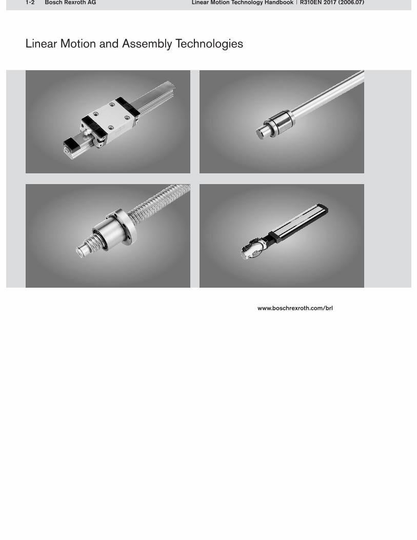
Linear Motion and Assembly Technologies
Linear Motion Technology Handbook R310EN 2017 (2006.07)

1-3Bosch Rexroth AGLinear Motion Technology HandbookR310EN 2017 (2006.07)
1 Introduction
Reliable guidance and precise positioning – Rexroth provides a complete linear motion technology range for these tasks, from guides through to drive units. Linear motion technology components are the interface between static and moving machine elements. They significantly affect the machine characteristics. Linear motion technology comes into play whenever precision and high load-bearing capability are required, as is above all the case in machine construction and automation. Rexroth’s guidance components are profiled rail systems and linear bushings and shafts. Ball screw assemblies are the drive components used for positioning. Both of these functions are combined in linear motion systems. However, Rexroth offers much more than just linear motion products. As a global equipment provider for machinery and plant construction, Rexroth provides all the relevant drive, control and motion technologies – from mechanics, hydraulics and pneumatics through to electronics.
This linear motion technology handbook provides specialized knowledge about Rexroth’s linear motion technology products, giving users insights into the world of linear motion. The handbook is not de-signed to replace the Rexroth product catalogs but simply as a supplement to them. The dimensions, performance data and product versions, etc. must still be taken from the catalogs. The handbook, however, contains extensive advice on system characteristics, product selection, design and calcula-tion. It is designed for all linear motion technology users.
The handbook is divided into a general Principles chapter, equally applicable to all Rexroth products, and into additional special chapters on the individual linear motion technology components.
The Principles chapter describes the physical background knowledge for linear motion technology. This includes rolling contact with all its usual practical manifestations, as well as generally accepted methods for calculating nominal life. Also described are system characteristics common to all prod-ucts, such as preload, rigidity, accuracy and friction. The following chapters on Profiled Rail Systems, Linear Bushings and Shafts, Ball Screw Drives and Linear Motion Systems refer to the respective Rexroth products and their characteristics. These chapters cover additional basic knowledge, system properties, advice on product selection, and design hints for users of these products. A substantial part of the handbook covers how to calculate, dimension and configure the guidance and drive com-ponents. This includes detailed calculation of the components’ life expectancy, calculation of the static load safety factors, determination of the critical screw speed, and drive dimensioning. The structural design and the functionalities of the individual types, versions and components are also described. The reader is therefore provided with an overview of each product’s special characteristics.
We hope that you will enjoy reading and using this handbook.
Bosch Rexroth AGThe Drive & Control CompanyLinear Motion and Assembly Technologies
1.1 Foreword

1-4 Bosch Rexroth AG Linear Motion Technology Handbook R310EN 2017 (2006.07)
1 Introduction
1.2 Contents
1 Introduction . . . . . . . . . . . . . . . . . . . . . 1-3
1.1 Foreword . . . . . . . . . . . . . . . . . . . . . . . . . . . . . . . 1-3
1.2 Contents . . . . . . . . . . . . . . . . . . . . . . . . . . . . . . . 1-4
2 Prinziples . . . . . . . . . . . . . . . . . . . . . . . . 2-1
2.1 Historical development . . . . . . . . . . . . . . . . . . 2-1
2.2 Technical principles . . . . . . . . . . . . . . . . . . . . . 2-32.2.1 Elements of a machine . . . . . . . . . . . . . . . . . . . . . . . 2-32.2.2 Guides . . . . . . . . . . . . . . . . . . . . . . . . . . . . . . . . . . . . . . 2-52.2.2.1 Differentiation of guides according to
the type of motion . . . . . . . . . . . . . . . . . . . . . . . . . . . .2-52.2.2.2 Differentiation of linear guides according to
the type of contact points . . . . . . . . . . . . . . . . . . . . .2-52.2.2.3 Operating principle of linear guides . . . . . . . . . . . . .2-62.2.2.4 Linear guide characteristics . . . . . . . . . . . . . . . . . . . .2-72.2.2.5 Differentiation of rolling contact guides according
to rolling element recirculation . . . . . . . . . . . . . . . . .2-72.2.3 Drive . . . . . . . . . . . . . . . . . . . . . . . . . . . . . . . . . . . . . . . . 2-82.2.3.1 Drive types . . . . . . . . . . . . . . . . . . . . . . . . . . . . . . . . . .2-82.2.3.2 Screw drive . . . . . . . . . . . . . . . . . . . . . . . . . . . . . . . . .2-9
2.3 Rolling contact . . . . . . . . . . . . . . . . . . . . . . . . . 2-102.3.1 Rolling contact of balls and rollers . . . . . . . . . . . .2-102.3.1.1 Contact areas in balls and rollers . . . . . . . . . . . . . .2-102.3.1.2 Ball contact conformity . . . . . . . . . . . . . . . . . . . . . . .2-112.3.1.3 Logarithmic and cylindrical roller profiles . . . . . . . .2-112.3.1.4 Elastic deflection of balls and rollers . . . . . . . . . . . .2-122.3.2 Running track geometry for
ball rolling elements . . . . . . . . . . . . . . . . . . . . . . . . .2-132.3.2.1 Arc-shaped raceways . . . . . . . . . . . . . . . . . . . . . . . .2-132.3.2.2 Differential slip . . . . . . . . . . . . . . . . . . . . . . . . . . . . . .2-14
2.4 Life expectancy . . . . . . . . . . . . . . . . . . . . . . . . 2-152.4.1 Calculation principles . . . . . . . . . . . . . . . . . . . . . . . .2-152.4.1.1 Nominal life . . . . . . . . . . . . . . . . . . . . . . . . . . . . . . . .2-152.4.1.2 Dynamic and static load capacities . . . . . . . . . . . . .2-162.4.1.3 Equivalent load on bearing . . . . . . . . . . . . . . . . . . . .2-182.4.1.4 Static load safety factor . . . . . . . . . . . . . . . . . . . . . .2-212.4.2 Conditions of use . . . . . . . . . . . . . . . . . . . . . . . . . . .2-222.4.2.1 Environmental conditions . . . . . . . . . . . . . . . . . . . . .2-222.4.2.2 Operating conditions . . . . . . . . . . . . . . . . . . . . . . . .2-242.4.2.3 Installation conditions . . . . . . . . . . . . . . . . . . . . . . . .2-252.4.2.4 Normal conditions of use . . . . . . . . . . . . . . . . . . . . .2-252.4.3 Damage profiles . . . . . . . . . . . . . . . . . . . . . . . . . . . .2-26
2.5 System technology . . . . . . . . . . . . . . . . . . . . 2-282.5.1 Preload and rigidity . . . . . . . . . . . . . . . . . . . . . . . . . .2-282.5.2 Friction . . . . . . . . . . . . . . . . . . . . . . . . . . . . . . . . . . . . .2-292.5.3 Sealing . . . . . . . . . . . . . . . . . . . . . . . . . . . . . . . . . . . . .2-302.5.4 Lubrication . . . . . . . . . . . . . . . . . . . . . . . . . . . . . . . . .2-312.5.4.1 Lubrication principles . . . . . . . . . . . . . . . . . . . . . . . .2-312.5.4.2 Lubricants . . . . . . . . . . . . . . . . . . . . . . . . . . . . . . . . .2-332.5.4.3 Lubrication intervals . . . . . . . . . . . . . . . . . . . . . . . . .2-352.5.5 Accuracy . . . . . . . . . . . . . . . . . . . . . . . . . . . . . . . . . . .2-362.5.5.1 Accuracy levels in guides and drive units . . . . . . . .2-362.5.5.2 Accuracy types in linear motion systems . . . . . . . .2-36
2.6 Product overview . . . . . . . . . . . . . . . . . . . . . . 2-37
1-5Bosch Rexroth AGLinear Motion Technology HandbookR310EN 2017 (2006.07)
1 Introduction
1.2 Contents
3 Profiled rail systems . . . . . . . . . . . . . 3-1
3.1 Principles . . . . . . . . . . . . . . . . . . . . . . . . . . . . . . 3-13.1.1 System technology . . . . . . . . . . . . . . . . . . . . . . . . . . . 3-13.1.1.1 Structural design of a profiled rail system . . . . . . . . .3-23.1.1.2 Load-bearing capability . . . . . . . . . . . . . . . . . . . . . . . .3-93.1.1.3 Preload . . . . . . . . . . . . . . . . . . . . . . . . . . . . . . . . . . . .3-143.1.1.4 Rigidity . . . . . . . . . . . . . . . . . . . . . . . . . . . . . . . . . . . .3-163.1.1.5 Accuracy . . . . . . . . . . . . . . . . . . . . . . . . . . . . . . . . . .3-183.1.1.6 Travel accuracy . . . . . . . . . . . . . . . . . . . . . . . . . . . . .3-213.1.1.7 Friction . . . . . . . . . . . . . . . . . . . . . . . . . . . . . . . . . . . .3-243.1.2 Product selection . . . . . . . . . . . . . . . . . . . . . . . . . . .3-263.1.2.1 Product selection aids . . . . . . . . . . . . . . . . . . . . . . .3-263.1.2.2 Product selection procedure . . . . . . . . . . . . . . . . . .3-303.1.3 Profiled rail system layout . . . . . . . . . . . . . . . . . . .3-333.1.3.1 Number of runner blocks and guide rails . . . . . . . .3-333.1.3.2 Mounting orientation of the profiled rail guide . . . .3-343.1.3.3 Guide rail mounting . . . . . . . . . . . . . . . . . . . . . . . . . .3-343.1.3.4 Runner block mounting . . . . . . . . . . . . . . . . . . . . . . .3-403.1.3.5 Design of the adjoining structure . . . . . . . . . . . . . . .3-413.1.3.6 Installation scenarios . . . . . . . . . . . . . . . . . . . . . . . . .3-473.1.4 Design notes . . . . . . . . . . . . . . . . . . . . . . . . . . . . . . .3-503.1.4.1 Installation tolerances . . . . . . . . . . . . . . . . . . . . . . . .3-503.1.4.2 Guidelines for economical designs . . . . . . . . . . . . .3-553.1.5 Calculations . . . . . . . . . . . . . . . . . . . . . . . . . . . . . . . .3-573.1.5.1 Procedure for manual calculations . . . . . . . . . . . . .3-573.1.5.2 Define the operating conditions . . . . . . . . . . . . . . . .3-593.1.5.3 Loads due to forces and moments . . . . . . . . . . . . .3-643.1.5.4 Combined equivalent load on bearing . . . . . . . . . . .3-713.1.5.5 Taking the preload into account . . . . . . . . . . . . . . .3-743.1.5.6 Equivalent dynamic load on bearing . . . . . . . . . . . .3-753.1.5.7 Life expectancy . . . . . . . . . . . . . . . . . . . . . . . . . . . . .3-763.1.5.8 Equivalent static load on bearing . . . . . . . . . . . . . . .3-793.1.5.9 Static load safety factor . . . . . . . . . . . . . . . . . . . . . .3-813.1.5.10 Example of a nominal life calculation . . . . . . . . . . . .3-813.1.6 Defining the peripherals . . . . . . . . . . . . . . . . . . . . .3-943.1.6.1 Lubrication . . . . . . . . . . . . . . . . . . . . . . . . . . . . . . . . .3-943.1.6.2 Sealing . . . . . . . . . . . . . . . . . . . . . . . . . . . . . . . . . . . .3-963.1.6.3 Corrosion protection . . . . . . . . . . . . . . . . . . . . . . . . .3-983.1.6.4 Additional functions . . . . . . . . . . . . . . . . . . . . . . . . .3-99
3.2 Ball rail systems . . . . . . . . . . . . . . . . . . . . . . 3-1013.2.1 System characteristics . . . . . . . . . . . . . . . . . . . . .3-1013.2.2 Structural design . . . . . . . . . . . . . . . . . . . . . . . . . . .3-1023.2.3 Product selection guide . . . . . . . . . . . . . . . . . . . . .3-1063.2.3.1 Versions . . . . . . . . . . . . . . . . . . . . . . . . . . . . . . . . . 3-1063.2.3.2 Application areas . . . . . . . . . . . . . . . . . . . . . . . . . . 3-106
3.3 Miniature ball rail systems . . . . . . . . . . . . . 3-1073.3.1 System characteristics . . . . . . . . . . . . . . . . . . . . .3-1073.3.2 Structural design . . . . . . . . . . . . . . . . . . . . . . . . . . .3-1083.3.3 Product selection guide . . . . . . . . . . . . . . . . . . . . .3-1113.3.3.1 Versions . . . . . . . . . . . . . . . . . . . . . . . . . . . . . . . . . 3-1113.3.3.2 Application areas . . . . . . . . . . . . . . . . . . . . . . . . . . 3-111
3.4 eLINE ball rail systems . . . . . . . . . . . . . . . . 3-1123.4.1 System characteristics . . . . . . . . . . . . . . . . . . . . .3-1123.4.2 Structural design . . . . . . . . . . . . . . . . . . . . . . . . . . .3-1133.4.3 Product selection guide . . . . . . . . . . . . . . . . . . . .3-1163.4.3.1 Versions . . . . . . . . . . . . . . . . . . . . . . . . . . . . . . . . . 3-1163.4.3.2 Application areas . . . . . . . . . . . . . . . . . . . . . . . . . . 3-1163.4.3.3 Simplified calculations . . . . . . . . . . . . . . . . . . . . . 3-116
3.5 Roller rail systems . . . . . . . . . . . . . . . . . . . . 3-1173.5.1 System characteristics . . . . . . . . . . . . . . . . . . . . .3-1173.5.2 Structural design . . . . . . . . . . . . . . . . . . . . . . . . . . .3-1183.5.3 Product selection guide . . . . . . . . . . . . . . . . . . . .3-1213.5.3.1 Versions . . . . . . . . . . . . . . . . . . . . . . . . . . . . . . . . . 3-1213.5.3.2 Application areas . . . . . . . . . . . . . . . . . . . . . . . . . . 3-121
3.6 Cam roller guides . . . . . . . . . . . . . . . . . . . . . 3-1223.6.1 System characteristics . . . . . . . . . . . . . . . . . . . . .3-1223.6.2 Structural design . . . . . . . . . . . . . . . . . . . . . . . . . . .3-1233.6.3 Product selection guide . . . . . . . . . . . . . . . . . . . . .3-1253.6.3.1 Versions . . . . . . . . . . . . . . . . . . . . . . . . . . . . . . . . . 3-1253.6.3.2 Application areas . . . . . . . . . . . . . . . . . . . . . . . . . . 3-1263.6.3.3 Different calculation procedure . . . . . . . . . . . . . . 3-126
3.7 Integrated measuring system . . . . . . . . . . 3-1273.7.1 Position measuring systems principles . . . . . .3-1273.7.2 System characteristics . . . . . . . . . . . . . . . . . . . . .3-1293.7.3 Structural design . . . . . . . . . . . . . . . . . . . . . . . . . . .3-1303.7.3.1 Components functions . . . . . . . . . . . . . . . . . . . . . 3-1313.7.3.2 Function description of the inductive sensors . . 3-1343.7.4 Electronics . . . . . . . . . . . . . . . . . . . . . . . . . . . . . . . .3-1363.7.5 Product selection guide . . . . . . . . . . . . . . . . . . . .3-1383.7.5.1 Accuracy of the measuring system . . . . . . . . . . . 3-1383.7.5.2 Application areas . . . . . . . . . . . . . . . . . . . . . . . . . . 3-138

1-6 Bosch Rexroth AG Linear Motion Technology Handbook R310EN 2017 (2006.07)
1 Introduction
1.2 Contents
4 Linear bushings and shafts . . . . . . . 4-1
4.1 Principles . . . . . . . . . . . . . . . . . . . . . . . . . . . . . . 4-14.1.1 System technology . . . . . . . . . . . . . . . . . . . . . . . . . . . 4-14.1.1.1 Structural design of a linear bushing . . . . . . . . . . . . .4-14.1.1.2 Structural design of a linear set . . . . . . . . . . . . . . . . .4-24.1.1.3 Structural design of shafts, shaft support blocks
and shaft support rails . . . . . . . . . . . . . . . . . . . . . . . . . 4-34.1.1.4 Standards . . . . . . . . . . . . . . . . . . . . . . . . . . . . . . . . . .4-34.1.1.5 Type designations and forms of linear bushings . . .4-44.1.2 Product selection . . . . . . . . . . . . . . . . . . . . . . . . . . . . 4-64.1.2.1 Linear bushing applications . . . . . . . . . . . . . . . . . . . .4-64.1.2.2 Linear bushing characteristics and technical data . .4-74.1.2.3 Application parameters . . . . . . . . . . . . . . . . . . . . . . . .4-84.1.2.4 Selection of appropriate linear bushings . . . . . . . . .4-84.1.3 Design notes . . . . . . . . . . . . . . . . . . . . . . . . . . . . . . .4-104.1.3.1 Influence of the direction of loading on
the load capacity . . . . . . . . . . . . . . . . . . . . . . . . . . . .4-104.1.3.2 Design measures . . . . . . . . . . . . . . . . . . . . . . . . . . . .4-114.1.3.3 Lubrication . . . . . . . . . . . . . . . . . . . . . . . . . . . . . . . . .4-144.1.4 Calculations . . . . . . . . . . . . . . . . . . . . . . . . . . . . . . . .4-164.1.4.1 Nominal life . . . . . . . . . . . . . . . . . . . . . . . . . . . . . . . .4-164.1.4.2 Equivalent dynamic load on bearing . . . . . . . . . . . .4-194.1.4.3 Resulting load . . . . . . . . . . . . . . . . . . . . . . . . . . . . . .4-194.1.4.4 Varying bearing loads from varying
load directions . . . . . . . . . . . . . . . . . . . . . . . . . . . . . .4-204.1.4.5 Torque considerations for torque-resistant
linear bushings . . . . . . . . . . . . . . . . . . . . . . . . . . . . .4-214.1.4.6 Static load safety factor . . . . . . . . . . . . . . . . . . . . . .4-224.1.4.7 Shaft deflection . . . . . . . . . . . . . . . . . . . . . . . . . . . . .4-224.1.5 Calculation example . . . . . . . . . . . . . . . . . . . . . . . . .4-23
4.2 Linear bushings . . . . . . . . . . . . . . . . . . . . . . . . 4-264.2.1 Compact and eLINE linear bushings . . . . . . . . . .4-264.2.2 Super linear bushings A and B . . . . . . . . . . . . . . .4-274.2.3 Standard linear bushings . . . . . . . . . . . . . . . . . . . .4-294.2.4 Segmental linear bushings . . . . . . . . . . . . . . . . . . .4-304.2.5 Super linear bushings H and SH . . . . . . . . . . . . .4-314.2.6 Radial linear bushings . . . . . . . . . . . . . . . . . . . . . . .4-324.2.7 Torque-resistant linear bushings . . . . . . . . . . . . .4-334.2.8 Linear bushings for combined linear and
rotary motion . . . . . . . . . . . . . . . . . . . . . . . . . . . . . . .4-34
4.3 Linear sets . . . . . . . . . . . . . . . . . . . . . . . . . . . . 4-35
4.4 Precision steel shafts . . . . . . . . . . . . . . . . . . 4-37
4.5 Shaft support rails . . . . . . . . . . . . . . . . . . . . . 4-38
4.6 Shaft support blocks . . . . . . . . . . . . . . . . . . . 4-39
5 Ball screw drives . . . . . . . . . . . . . . . . . 5-1
5.1 Principles . . . . . . . . . . . . . . . . . . . . . . . . . . . . . . 5-15.1.1 System technology . . . . . . . . . . . . . . . . . . . . . . . . . . . 5-15.1.1.1 Structural design of a ball screw assembly . . . . . . .5-25.1.1.2 Load ratings . . . . . . . . . . . . . . . . . . . . . . . . . . . . . . . . .5-95.1.1.3 Preload . . . . . . . . . . . . . . . . . . . . . . . . . . . . . . . . . . . .5-105.1.1.4 Rigidity . . . . . . . . . . . . . . . . . . . . . . . . . . . . . . . . . . . .5-125.1.1.5 Accuracy . . . . . . . . . . . . . . . . . . . . . . . . . . . . . . . . . .5-145.1.1.6 Dynamic drag torque . . . . . . . . . . . . . . . . . . . . . . . .5-165.1.1.7 Characteristic speed and maximum linear speed . .5-175.1.1.8 Mechanical efficiency . . . . . . . . . . . . . . . . . . . . . . . .5-175.1.1.9 Lubrication . . . . . . . . . . . . . . . . . . . . . . . . . . . . . . . . .5-185.1.2 Product selection . . . . . . . . . . . . . . . . . . . . . . . . . . .5-195.1.2.1 Guide to choosing the right product . . . . . . . . . . . .5-195.1.2.2 Product selection procedure . . . . . . . . . . . . . . . . . .5-205.1.2.3 Pre-selection . . . . . . . . . . . . . . . . . . . . . . . . . . . . . . .5-205.1.3 Calculations . . . . . . . . . . . . . . . . . . . . . . . . . . . . . . . .5-215.1.3.1 Defining the requirements . . . . . . . . . . . . . . . . . . . .5-215.1.3.2 Life expectancy . . . . . . . . . . . . . . . . . . . . . . . . . . . . .5-235.1.3.3 Critical speed . . . . . . . . . . . . . . . . . . . . . . . . . . . . . .5-275.1.3.4 Permissible axial load on screw (buckling load) . . .5-285.1.3.5 End bearings . . . . . . . . . . . . . . . . . . . . . . . . . . . . . . .5-295.1.3.6 Drive torque and drive power . . . . . . . . . . . . . . . . . .5-295.1.3.7 Calculation example . . . . . . . . . . . . . . . . . . . . . . . . .5-305.1.4 Design notes . . . . . . . . . . . . . . . . . . . . . . . . . . . . . . .5-365.1.4.1 Adjoining structures and installation tolerances . . .5-365.1.4.2 Guidelines for economical constructions . . . . . . . .5-375.1.4.3 Safety nuts for vertical applications . . . . . . . . . . . . .5-385.1.5 Mounting instructions . . . . . . . . . . . . . . . . . . . . . . .5-39
5.2 Ball nuts . . . . . . . . . . . . . . . . . . . . . . . . . . . . . . 5-405.2.1 Single nuts . . . . . . . . . . . . . . . . . . . . . . . . . . . . . . . . .5-405.2.1.1 System characteristics . . . . . . . . . . . . . . . . . . . . . . .5-405.2.1.2 Application areas . . . . . . . . . . . . . . . . . . . . . . . . . . . .5-405.2.2 Standard series single nuts . . . . . . . . . . . . . . . . . .5-415.2.2.1 System characteristics . . . . . . . . . . . . . . . . . . . . . . .5-415.2.2.2 Application areas . . . . . . . . . . . . . . . . . . . . . . . . . . . .5-415.2.3 Miniature series single nuts . . . . . . . . . . . . . . . . . .5-425.2.3.1 System characteristics . . . . . . . . . . . . . . . . . . . . . . .5-425.2.3.2 Application areas . . . . . . . . . . . . . . . . . . . . . . . . . . . .5-425.2.4 eLINE series single nuts . . . . . . . . . . . . . . . . . . . . .5-435.2.4.1 System characteristics . . . . . . . . . . . . . . . . . . . . . . .5-435.2.4.2 Application areas . . . . . . . . . . . . . . . . . . . . . . . . . . . .5-435.2.5 Double nuts . . . . . . . . . . . . . . . . . . . . . . . . . . . . . . . .5-445.2.5.1 System characteristics . . . . . . . . . . . . . . . . . . . . . . .5-445.2.5.2 Application areas . . . . . . . . . . . . . . . . . . . . . . . . . . . .5-44
5.3 Drive units . . . . . . . . . . . . . . . . . . . . . . . . . . . . . 5-455.3.1 Drive units with driven screw . . . . . . . . . . . . . . . . .5-455.3.1.1 System characteristics . . . . . . . . . . . . . . . . . . . . . . .5-455.3.1.2 Application areas . . . . . . . . . . . . . . . . . . . . . . . . . . . .5-475.3.2 Drive units with driven nut . . . . . . . . . . . . . . . . . . .5-485.3.2.1. System characteristics . . . . . . . . . . . . . . . . . . . . . . .5-485.3.2.2 Application areas . . . . . . . . . . . . . . . . . . . . . . . . . . . .5-49
1-7Bosch Rexroth AGLinear Motion Technology HandbookR310EN 2017 (2006.07)
1 Introduction
1.2 Contents
6 Linear motion systems . . . . . . . . . . . 6-1
6.1 Principles . . . . . . . . . . . . . . . . . . . . . . . . . . . . . . 6-16.1.1 System technology . . . . . . . . . . . . . . . . . . . . . . . . . . . 6-16.1.1.1 Basic structural design of linear motion systems . . .6-36.1.1.2 Type and size designations . . . . . . . . . . . . . . . . . . .6-106.1.1.3 Guideway types . . . . . . . . . . . . . . . . . . . . . . . . . . . . .6-116.1.1.4 Drive unit types . . . . . . . . . . . . . . . . . . . . . . . . . . . . .6-146.1.2 Product selection . . . . . . . . . . . . . . . . . . . . . . . . . . .6-186.1.2.1 Application parameters . . . . . . . . . . . . . . . . . . . . . . .6-186.1.2.2 Product selection aids . . . . . . . . . . . . . . . . . . . . . . .6-206.1.2.3 Motor, controller and control system . . . . . . . . . . . .6-216.1.2.4 Conditions of use . . . . . . . . . . . . . . . . . . . . . . . . . . .6-216.1.3 Design notes . . . . . . . . . . . . . . . . . . . . . . . . . . . . . . .6-236.1.3.1 General design notes for linear motion systems . .6-236.1.3.2 Fastening linear motion systems to
the mounting base . . . . . . . . . . . . . . . . . . . . . . . . . . .6-256.1.4 Calculations . . . . . . . . . . . . . . . . . . . . . . . . . . . . . . . .6-266.1.4.1 External loads and nominal life calculation . . . . . . .6-266.1.4.2 Motor design calculations, including cycle times . .6-276.1.4.3 Deflection . . . . . . . . . . . . . . . . . . . . . . . . . . . . . . . . . .6-30
6.2 Linear modules . . . . . . . . . . . . . . . . . . . . . . . . 6-316.2.1 System characteristics . . . . . . . . . . . . . . . . . . . . . .6-316.2.2 Linear modules MKK with ball rail system
and ball screw drive . . . . . . . . . . . . . . . . . . . . . . . . .6-326.2.3 Linear modules MKR/MLR with ball rail system/
cam roller guide and toothed belt drive . . . . . . . . .6-336.2.4 Linear modules MKR/MKZ with two ball rail systems
and toothed belt/rack and pinion drive . . . . . . . . . . . .6-346.2.5 Linear modules MKP with ball rail system and
pneumatic drive . . . . . . . . . . . . . . . . . . . . . . . . . . . . .6-356.2.6 Linear modules MKL and LKL with
ball rail systems and linear motor . . . . . . . . . . . .6-366.2.7 Connection elements for linear modules . . . . . .6-37
6.3 Compact modules . . . . . . . . . . . . . . . . . . . . . 6-386.3.1 System characteristics . . . . . . . . . . . . . . . . . . . . . .6-386.3.2 Compact modules CKK with ball rail systems
and ball screw drive . . . . . . . . . . . . . . . . . . . . . . . . .6-396.3.3 Compact modules CKR with ball rail systems
and toothed belt drive . . . . . . . . . . . . . . . . . . . . . . .6-406.3.4 Compact modules CKL with ball rail systems
and linear motor . . . . . . . . . . . . . . . . . . . . . . . . . . . .6-416.3.5 Connection elements and Easy-2-Combine
automation system . . . . . . . . . . . . . . . . . . . . . . . . . .6-42
6.4 Precision modules . . . . . . . . . . . . . . . . . . . . . 6-436.4.1 System characteristics . . . . . . . . . . . . . . . . . . . . . .6-43
6.5 Ball rail tables . . . . . . . . . . . . . . . . . . . . . . . . . 6-456.5.1 System characteristics . . . . . . . . . . . . . . . . . . . . . .6-456.5.2 Ball rail tables TKK with ball rail systems
and ball screw drive . . . . . . . . . . . . . . . . . . . . . . . . .6-46
6.5.3 Ball rail tables TKL with ball rail systems and linear motor . . . . . . . . . . . . . . . . . . . . . . . . . . . .6-47
6.6 Linear motion slides . . . . . . . . . . . . . . . . . . . 6-486.6.1 System characteristics . . . . . . . . . . . . . . . . . . . . . .6-48
6.7 Cartesian motion systems . . . . . . . . . . . . . . 6-496.7.1 System characteristics . . . . . . . . . . . . . . . . . . . . . .6-496.7.2 Basic structure of the CMS. . . . . . . . . . . . . . . . . . .6-50
6.8 Electrical components . . . . . . . . . . . . . . . . . . 6-516.8.1 Overview . . . . . . . . . . . . . . . . . . . . . . . . . . . . . . . . . . .6-516.8.2 Motors . . . . . . . . . . . . . . . . . . . . . . . . . . . . . . . . . . . . .6-526.8.2.1 Servo motors . . . . . . . . . . . . . . . . . . . . . . . . . . . . . . .6-536.8.2.2 Linear motors . . . . . . . . . . . . . . . . . . . . . . . . . . . . . . .6-546.8.2.3 Three-phase motors . . . . . . . . . . . . . . . . . . . . . . . . .6-556.8.2.4 Stepping motors . . . . . . . . . . . . . . . . . . . . . . . . . . . .6-556.8.3 Controllers and control systems . . . . . . . . . . . . . .6-566.8.3.1 Servo controllers . . . . . . . . . . . . . . . . . . . . . . . . . . . .6-576.8.3.2 Frequency inverters . . . . . . . . . . . . . . . . . . . . . . . . . .6-586.8.3.3 Positioning control . . . . . . . . . . . . . . . . . . . . . . . . . .6-586.8.3.4 Path control . . . . . . . . . . . . . . . . . . . . . . . . . . . . . . . .6-596.8.3.5 Control cabinet solutions . . . . . . . . . . . . . . . . . . . . .6-596.8.4 Switches and sensors . . . . . . . . . . . . . . . . . . . . . . .6-606.8.4.1 Mechanical switches . . . . . . . . . . . . . . . . . . . . . . . . .6-616.8.4.2 Proximity switches . . . . . . . . . . . . . . . . . . . . . . . . . . .6-616.8.4.3 Hall sensors . . . . . . . . . . . . . . . . . . . . . . . . . . . . . . . .6-616.8.4.4 Reed sensors . . . . . . . . . . . . . . . . . . . . . . . . . . . . . . .6-626.8.4.5 Switch mounting arrangements . . . . . . . . . . . . . . . .6-62

1-8 Bosch Rexroth AG Linear Motion Technology Handbook R310EN 2017 (2006.07)
1 Introduction
1.2 Contents
7 Appendix . . . . . . . . . . . . . . . . . . . . . . . . 7-1
7.1 Bosch Rexroth AG: The Drive & Control Company . . . . . . . . . . . . 7-17.1.1 A strong partner worldwide . . . . . . . . . . . . . . . . . . . 7-17.1.2 Linear motion and assembly technologies . . . . . 7-17.1.2.1 Linear motion technology . . . . . . . . . . . . . . . . . . . . . .7-27.1.2.2 Assembly technology . . . . . . . . . . . . . . . . . . . . . . . . .7-4
7.2 Glossary . . . . . . . . . . . . . . . . . . . . . . . . . . . . . . . 7-6
7.3 Index . . . . . . . . . . . . . . . . . . . . . . . . . . . . . . . . . . 7-9

2-1Bosch Rexroth AG
2 Principles
Linear Motion Technology HandbookR310EN 2017 (2006.07)
2.1 Historical development
When building the pyramids, the Egyptians had already encountered the problem of how to move heavy loads. This was solved by using tree trunks laid under blocks of stone. Water was also ap-plied as a lubricant to reduce friction.
Linear motion
Rolling contact profiled rail systems
This basic principle is still used today in modern linear motion guides. The rolling elements nowa-days, however, no longer have to be carried to the desired position by hand but instead recirculate within the guide system itself. The requirements regarding rigidity, load-bearing capacity and resistance to movement have also changed. Ap-plications today place the highest demands on precision and economy.
Historical illustration of a ball rail system
Round guides In 1957, “Deutsche Star” signed a license con-tract to manufacture ball bushings in accordance with the patents held by the US-based Thomson company. “Deutsche Star” therefore became the leading manufacturer of linear bearings in Europe.
Egyptian linear motion guide
“Deutsche Star” catalog

2-2 Bosch Rexroth AG
2 Principles
Linear Motion Technology Handbook R310EN 2017 (2006.07)
Ball screw drive
Ball screw drive from a historical patent
Linear motion systems
2.1 Historical development
Sliding screw drives were already used in Antiq-uity to convert rotary motion into linear motion. The ball screw drive was first mentioned in litera-ture in the 19th century. It replaced sliding friction with rolling friction. It was first used industrially in the 1940s, when General Motors built ball screw drives into vehicle steering systems. Further in-dustrial applications soon followed. Since then, the design and manufacturing processes have made enormous progress. Today, ball screw drives are found in a broad range of industries.
Linear motion systems are ready-to-install drive and guidance units. This makes it easier for users to design and assemble their applications. It is not necessary to calculate and dimension the individual components, since the linear motion systems are installed as complete units.The first linear motion systems built by the former “Deutsche Star” consisted of linear bushings and shafts and a ball screw or pneumatic drive. These transfer tables were also offered as two-axis X-Y tables. Meanwhile, many different guide and drive unit variants have been incorporated into linear motion systems. Today, customers can select the optimal linear motion system from a broad range of Rexroth products.
X-Y table from the “Deutsche Star“ product range
2-3Bosch Rexroth AG
2 Principles
Linear Motion Technology HandbookR310EN 2017 (2006.07)
2.2 Technical principles2.2.1 Elements of a machine
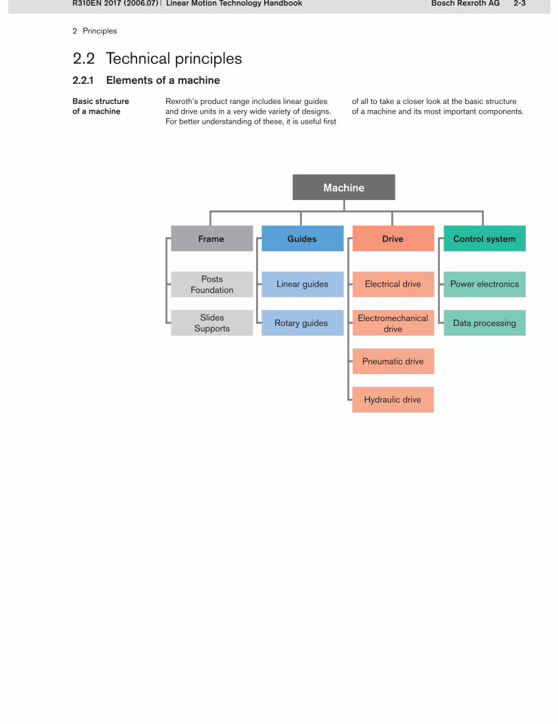
Basic structure of a machine
Rexroth’s product range includes linear guides and drive units in a very wide variety of designs. For better understanding of these, it is useful first
of all to take a closer look at the basic structure of a machine and its most important components.
SlidesSupports
PostsFoundation
Frame
Rotary guides
Linear guides
Guides
Data processing
Power electronics
Control system
Electromechanicaldrive
Pneumatic drive
Hydraulic drive
Electrical drive
Drive
Machine

2-4 Bosch Rexroth AG
2 Principles
Linear Motion Technology Handbook R310EN 2017 (2006.07)
2.2 Technical principles2.2.1 Elements of a machine
Elements of a machine (example) Frame
Control system
Guides
Drive
Machine with typical linear components shown in color
A machine’s frame consists of stationary com- ponents (posts, foundation) and moving com- ponents (slides, supports). There are various designs to suit the corresponding application (standard machine base, gantry design, etc.)
FrameFrame The frame’s purpose is to anchor the machine and to transmit forces.
These are responsible for the guidance and pow-er transmission of the moving machine compo-nents. The machine’s accuracy is due in no small
GuidesGuides measure to the accuracy of the guidance system. Based on the movement, a distinction is made between linear guidance and rotary guidance.
Drives convert electrical, hydraulic or pneumatic energy into mechanical energy. Electromechani-cal drives are a special form of drive incorporating transmission elements (e.g. ball screw drives). A distinction is made between main drives, which
DrivesDrives execute relative movements (e.g. between a tool and a workpiece), and auxiliary drives, which execute positioning movements (e.g. workpiece transport or tool changing).
The control system coordinates the requisite movements of the machine, i.e. the moving parts’ speed and acceleration. The power electronics serves the motors and high-powered actuators,
Control systemControl system whereas the data processing system covers the limit switches, measuring systems, field bus systems and the safety circuits.

2-5Bosch Rexroth AG
2 Principles
Linear Motion Technology HandbookR310EN 2017 (2006.07)
2.2 Technical principles2.2.2 Guides
2.2.2.1 Differentiation of guides according to the type of motion
Machines could not execute movements without guidance components. Depending on the guide’s design, forces and moments can be transmitted in certain directions between moving and non-moving components. Guides can generally be differentiated according to their type of motion.
Linear guides
Rotary motion takes place about an axis.Examples: deep groove ball bearings, radial sliding bearings
Rotary guidesRotary guides
2.2.2.2 Differentiation of linear guides according to the type of contact points
Linear guides can be differentiated according to the physical operating principle of the contact point, as is shown in the following diagram.
Guides are differentiated according to the type of motion, the type of contact points and the rolling element recirculation principle used.
Linear motion takes place along an axis.Examples: ball rail systems, dovetail sliders
Rotary guide
Linear guide
Roller guides
Ball guides
Cam roller guides
Hydrostatic guides
Fluidostatic guides
Aerostatic guides
Metal/metal
Rolling contact guides
Hydrodynamic guides
Metal/plastic
Linear guides
Sliding guides Magnetic guides
2-6 Bosch Rexroth AG
2 Principles
Linear Motion Technology Handbook R310EN 2017 (2006.07)
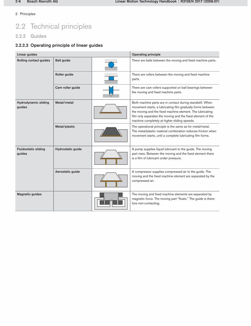
Linear guides Operating principle
Rolling contact guides Ball guide There are balls between the moving and fixed machine parts.
Roller guide There are rollers between the moving and fixed machine parts.
Cam roller guide There are cam rollers supported on ball bearings between the moving and fixed machine parts.
Hydrodynamic sliding guides
Metal/metal Both machine parts are in contact during standstill. When movement starts, a lubricating film gradually forms between the moving and the fixed machine element. The lubricating film only separates the moving and the fixed element of the machine completely at higher sliding speeds.
Metal/plastic The operational principle is the same as for metal/metal. The metal/plastic material combination reduces friction when movement starts, until a complete lubricating film forms.
Fluidostatic sliding guides
Hydrostatic guide A pump supplies liquid lubricant to the guide. The moving part rises. Between the moving and the fixed element there is a film of lubricant under pressure.
Aerostatic guide A compressor supplies compressed air to the guide. The moving and the fixed machine element are separated by the compressed air.
Magnetic guides The moving and fixed machine elements are separated by magnetic force. The moving part “floats.” The guide is there-fore non-contacting.
2.2 Technical principles2.2.2 Guides
2.2.2.3 Operating principle of linear guides
2-7Bosch Rexroth AG
31 21
2
3
2 Principles
Linear Motion Technology HandbookR310EN 2017 (2006.07)
2.2.2 Guides
2.2 Technical principles
Characteristics Rolling contact guides Hydrodynamic sliding guides
Fluidostatic sliding guides
Magnetic guide
Ball guide
Roller guide
Cam roller guide
Metal/ metal
Metal/ plastic
Hydrostatic guide
Aerostatic guide
Magnetic suspension
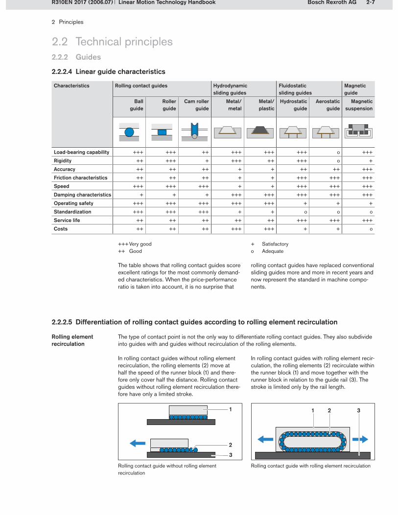
Load-bearing capability +++ +++ ++ +++ +++ +++ o +++
Rigidity ++ +++ + +++ ++ +++ o +
Accuracy ++ ++ ++ + + ++ ++ +++
Friction characteristics ++ ++ ++ + + +++ +++ +++
Speed +++ +++ +++ + + +++ +++ +++
Damping characteristics + + + +++ +++ +++ +++ +++
Operating safety +++ +++ +++ +++ +++ + + +
Standardization +++ +++ +++ + + o o o
Service life ++ ++ ++ ++ ++ +++ +++ +++
Costs ++ ++ ++ +++ +++ + + o
+++ Very good++ Good
2.2.2.4 Linear guide characteristics
The table shows that rolling contact guides score excellent ratings for the most commonly demand-ed characteristics. When the price-performance ratio is taken into account, it is no surprise that
The type of contact point is not the only way to differentiate rolling contact guides. They also subdivide into guides with and guides without recirculation of the rolling elements.
Rolling element recirculation
Rolling contact guide without rolling element recirculation
Rolling contact guide with rolling element recirculation
rolling contact guides have replaced conventional sliding guides more and more in recent years and now represent the standard in machine compo-nents.
2.2.2.5 Differentiation of rolling contact guides according to rolling element recirculation
+ Satisfactoryo Adequate
In rolling contact guides without rolling element recirculation, the rolling elements (2) move at half the speed of the runner block (1) and there-fore only cover half the distance. Rolling contact guides without rolling element recirculation there-fore have only a limited stroke.
In rolling contact guides with rolling element recir-culation, the rolling elements (2) recirculate within the runner block (1) and move together with the runner block in relation to the guide rail (3). The stroke is limited only by the rail length.

2-8 Bosch Rexroth AG
2 Principles
Linear Motion Technology Handbook R310EN 2017 (2006.07)
2.2.3 Drive
2.2 Technical principles
2.2.3.1 Drive types
Electrical, electromechanical, pneumatic or hydraulic drives can be used for main and auxiliary drives.
Among the electromechanical drives, the ball screw drive belongs to the sub-category of transmission elements. It is also frequently called a feed component.
e.g. linear motor
Electrical drive
Gearboxese.g. planetary gears
Motore.g. servomotor
Transmission elements
e.g. screw drive, toothed belt drive
Electro-mechanical
drive
e.g. hydraulic cylinder
Hydraulic drive
e.g. pneumatic cylinder
e.g. pneumatic cylinder
Pneumatic drive
Drive

2-9Bosch Rexroth AG
1
4
5
3
2
2 Principles
Linear Motion Technology HandbookR310EN 2017 (2006.07)
2.2.3 Drive
2.2 Technical principles
2.2.3.2 Screw drive
The following illustration of a Ball Rail Table TKK shows the typical structural design of a drive unit with ball screw drive together with rail guides.
Structural designStructural design
In a screw drive, a rotational movement takes place about an axis with a defined screw lead. Here rotary motion is converted into linear motion and vice versa.In mechanical engineering, screw drives are clas-sified as drive elements (transmission elements, feed elements).Examples: ball screws (BS), acme screws
DIN 69051 Part 1 defines a ball screw as follows:An assembly comprising a ball screw shaft and a ball nut and which is capable of converting rotary motion into linear motion and vice versa. The roll-ing elements of the assembly are balls.
Screw driveScrew drive
DIN 69051 Part 1Ball screw driveDIN 69051 Part 1Ball screw drive
Ball screw driveCarriageGuide railMotorGear unit (here: timing belt side drive)
1�2�3�4�5�
Screw drive
Ball Rail Table TKK with ball screw drive and ball rail system

2-10 Bosch Rexroth AG
2 Principles
Linear Motion Technology Handbook R310EN 2017 (2006.07)
2.3.1 Rolling contact of balls and rollers
2.3 Rolling contact
The rolling contact considerations for balls are based on the Hertz theory. This deals with the behavior of two curved bodies when they are pressed against each other by an external force. The elastic deformation, the dimensions of the compression areas, the maximum surface pres-sure and the sub-surface stresses occurring dur-ing the rolling contact of balls can be calculated using the Hertz theory.
The simplest case is the contact of a sphere with a plane (idealized point contact). In this case, there is a relatively small circular contact area, leading to a very high surface pressure.
If balls with different diameters are compared, it becomes apparent that, in the case of larger balls, the deformation and the surface pressure are smaller under the same load. The load-bear-ing capacity therefore rises as the ball diameter increases.
The Hertz theory does not apply to deformation in the case of line contact. If two cylindrical rollers are pressed together with their axes parallel, a line-shaped contact is produced. The resulting contact area is elongated, with the shape and size of the contact area dependent only on the load and the length of the contact line. Elastic deformation during line contact is independent of the roller diameter. At a constant roller diameter, the load-bearing capacity rises with increasing roller length.
Line contact in the case of rollersLine contact in the case of rollers
Point contact for ball rolling elements
Contact area for balls and rollers under increasing load
2.3.1.1 Contact areas in balls and rollers
In linear motion technology, balls or rollers are used as the rolling elements. Balls and rollers have differ-ent characteristics because of their different geometries.
The Hertz theory
Line contact for roller rolling elements
Rollers have a larger contact area than balls. This larger contact area enables the rollers to transmit greater forces, leading to greater rigidity. Compa-red to balls, therefore, smaller sizes can be used to bear the same external load.
Contact areaContact area
Point contact in the case of balls

2-11Bosch Rexroth AG
2 Principles
Linear Motion Technology HandbookR310EN 2017 (2006.07)
2.3.1 Rolling contact of balls and rollers
2.3 Rolling contact
Stress distribution for cylindrical roller profiles
Stress distribution for logarithmic roller profiles
Stress distribution for a contact area without conformity
2.3.1.2 Ball contact conformity
= conformity (%)RLb = running track radius (mm)DW = ball diameter (mm)
A ball on a running track designed for contact conformity will deflect significantly less than a comparable ball on a planar running track. Also, where there is conformity between the ball and the track, the ball will have a longer life than a ball with point contact because of the larger contact area and the resulting distribution of the forces acting on it.
In the case of rolling ball contact with planar running tracks, the high surface pressure and the absence of guided movement have an unfavor-able effect. For these reasons, profiled running tracks offering contact conformity are used. This increases the contact area and reduces the surface pressure accordingly. Higher load-bearing capabilities can therefore be achieved. This also serves to guide the movement of the rolling element.
Conformity is the ratio of the running track radius to the ball diameter, expressed as a percentage:
Running tracks with contact conformityRunning tracks with contact conformity
Definition of conformityDefinition of conformity
Stress distribution for a contact area with conformity
2.3.1.3 Logarithmic and cylindrical roller profiles
(2-1)
Rolling contact with rollers differs from that with balls. A distinction is made between rollers with cylindrical and logarithmic profiles. Both forms are approximately comparable in terms of their elastic deflection behavior.Rollers with logarithmic profiles, however, offer further advantages:
More even distribution of forcesLower peak stresses at the edges Correspondingly less edge contact
This results in longer life than with cylindrical rollers. Rexroth therefore uses rollers with loga-rithmic profiles.
Logarithmic profileLogarithmic profile
= · 100%RLbDW

2-12 Bosch Rexroth AG
2 Principles
Linear Motion Technology Handbook R310EN 2017 (2006.07)
2.3.1 Rolling contact of balls and rollers
2.3 Rolling contact
Elastic deflection Elastic deflection means that no permanent deformation of the parts in contact occurs.Depending on the type of rolling element and the shape and area of the contacting surfaces, a force acting on the rolling element will lead to different degrees of elastic deflection:
Rollers deflect less than balls. Rollers have a significantly higher rigidity and a higher load-bearing capacity because of the larger contact area.The deflection behavior of rollers with logarithmic profiles and rollers with cylindrical profiles are approximately comparable.A ball on a running track with conformity will deflect significantly less than a comparable ball on a track with no conformity.
The graph shows the elastic deflection for the rolling contact conditions described.
Elas
tic d
eflec
tion e
l
Force F
– Ball and running track with no conformity – Ball and running track with conformity – Roller with logarithmic profile– Roller with cylindrical profile
Assumptions:Balls and rollers with the same diameter Rollers in standard lengths
2.3.1.4 Elastic deflection of balls and rollers
Exemplary comparison of elastic deflection in balls and rollers
2-13Bosch Rexroth AG
2 Principles
Linear Motion Technology HandbookR310EN 2017 (2006.07)
2.3.2 Running track geometry for ball rolling elements
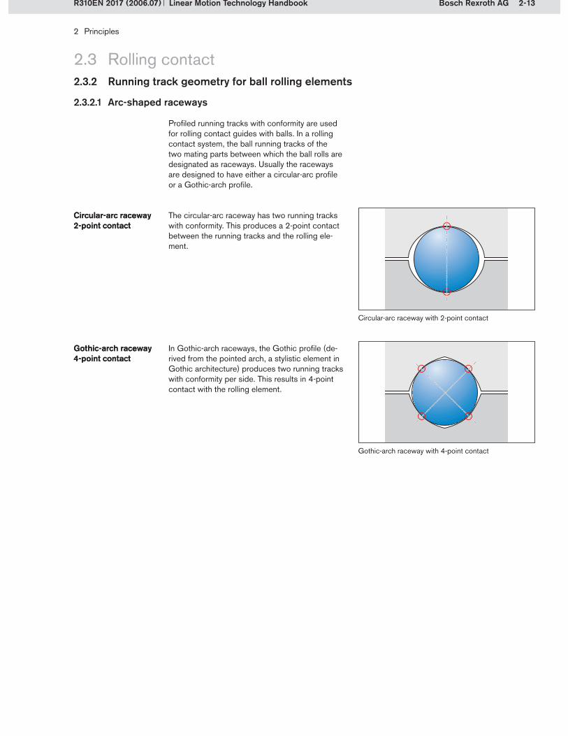
Profiled running tracks with conformity are used for rolling contact guides with balls. In a rolling contact system, the ball running tracks of the two mating parts between which the ball rolls are designated as raceways. Usually the raceways are designed to have either a circular-arc profile or a Gothic-arch profile.
The circular-arc raceway has two running tracks with conformity. This produces a 2-point contact between the running tracks and the rolling ele-ment.
Circular-arc raceway2-point contactCircular-arc raceway2-point contact
Circular-arc raceway with 2-point contact
Gothic-arch raceway with 4-point contact
2.3 Rolling contact
2.3.2.1 Arc-shaped raceways
In Gothic-arch raceways, the Gothic profile (de-rived from the pointed arch, a stylistic element in Gothic architecture) produces two running tracks with conformity per side. This results in 4-point contact with the rolling element.
Gothic-arch raceway4-point contactGothic-arch raceway4-point contact
2-14 Bosch Rexroth AG
!
!
d1 d2
· d1
· d2
DS
DS
2 Principles
Linear Motion Technology Handbook R310EN 2017 (2006.07)
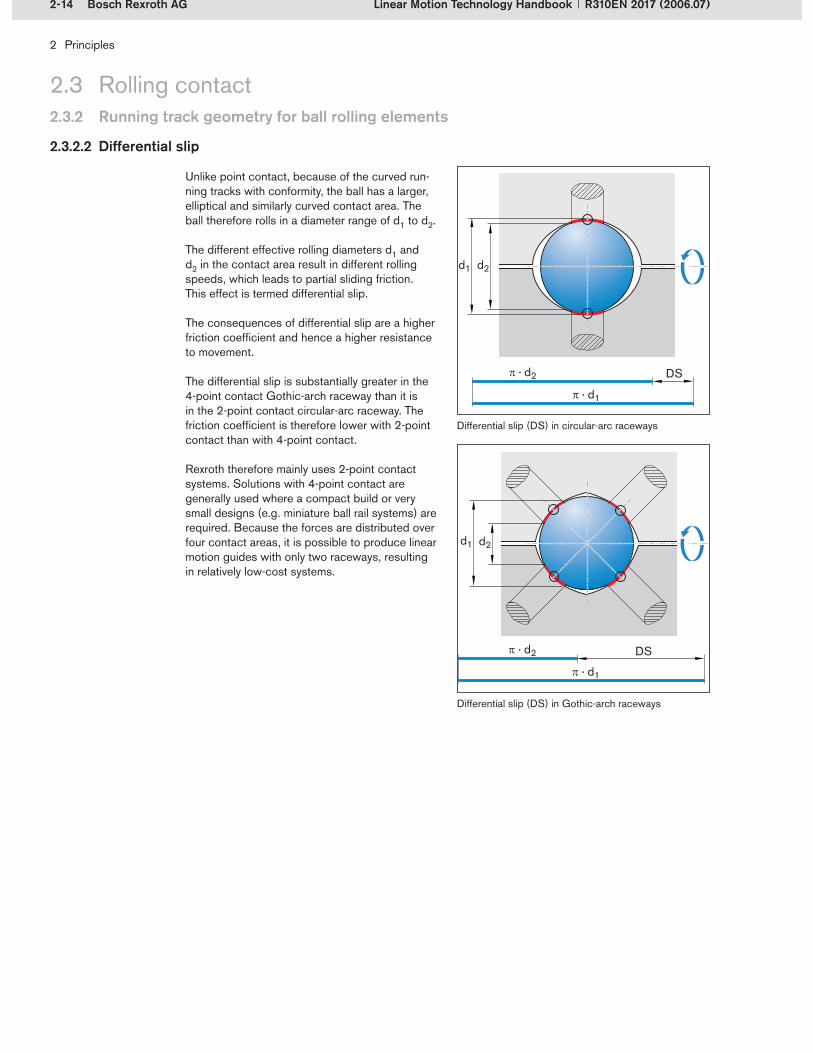
Unlike point contact, because of the curved run-ning tracks with conformity, the ball has a larger, elliptical and similarly curved contact area. The ball therefore rolls in a diameter range of d1 to d2.
The different effective rolling diameters d1 and d2 in the contact area result in different rolling speeds, which leads to partial sliding friction. This effect is termed differential slip.
The consequences of differential slip are a higher friction coefficient and hence a higher resistance to movement.
The differential slip is substantially greater in the 4-point contact Gothic-arch raceway than it is in the 2-point contact circular-arc raceway. The friction coefficient is therefore lower with 2-point contact than with 4-point contact.
Rexroth therefore mainly uses 2-point contact systems. Solutions with 4-point contact are generally used where a compact build or very small designs (e.g. miniature ball rail systems) are required. Because the forces are distributed over four contact areas, it is possible to produce linear motion guides with only two raceways, resulting in relatively low-cost systems.
Differential slip (DS) in circular-arc raceways
Differential slip (DS) in Gothic-arch raceways
2.3.2.2 Differential slip
2.3.2 Running track geometry for ball rolling elements
2.3 Rolling contact

2-15Bosch Rexroth AG
L = CF
p(2-2)
2 Principles
Linear Motion Technology HandbookR310EN 2017 (2006.07)
2.4.1 Calculation principles
2.4 Life expectancy
2.4.1.1 Nominal life
The nominal life L is the distance that a compo-nent can cover before the first signs of fatigue appear on the running tracks or rolling elements.Lundberg and Palmgren have developed a calcu-lation method for predicting the life expectancy of an anti-friction bearing as a function of the loading.
Nominal life LNominal life L
L = nominal life (100 km for linear guides or 1 million
revolutions for ball screw assemblies)C = dynamic load capacity (N)F = bearing loading and/or sum of external
force components acting on the bearing (N)p = exponent of the nominal life equation,
depending on the type of rolling element (–)
p = 3for linear ball bearings and ball screw assembliesp = 10/3for linear roller bearings
This calculation method is based on the Hertz theory, which enables statements to be made about the maximum surface pressure of two curved bodies. The dynamic load capacities are calculated from this, dependent on the surface factors.
The load capacities resulting from calculation ac-cording to the standard are often clearly exceed-ed by Rexroth in statistically-confirmed endurance tests – a result of their comprehensive system know-how.
An individual bearing’s probability of survival is the probability that the bearing will achieve or exceed a certain service life. The probability of survival is therefore a percentage of a group of
Probability of survivalProbability of survival identical bearings that have the same calculated life expectancy when operating under identical conditions.
In the case of linear motion guides, the life expec-tancy is related to the distance traveled and with ball screw drives to the number of revolutions. For both systems the life expectancy calculation is similar to the method given in DIN ISO 281 for rolling bearings. This calculation method is based on a fatigue theory which draws on the alternating shear stress hypothesis.

2-16 Bosch Rexroth AG
Lna = a1 ·CF
p
2 Principles
Linear Motion Technology Handbook R310EN 2017 (2006.07)
2.4.1.2 Dynamic and static load capacities
Dynamic load capacities are used as a basis for calculating life expectancy. Static load capacities are required for checking the static load safety factor. Specific details are provided in the correspond-ing product catalogs. Detailed descriptions of the calculation method are provided in the sub- sections for the specific guide and drive units.
National and international standards establish the methods for calculating dynamic and static load capacities.
Profiled rail systems and linear bushings and shafts per ISO 14728 Parts 1 and 2Ball screw assemblies per DIN 69051 Part 4
The dynamic load capacity C represents the load-ing at which a sufficiently large number of identi-cal bearings achieves the nominal life expectancy. In the case of ball screw drives and rotating anti-friction bearings, the nominal life expectancy is
Dynamic load capacity CDynamic load capacity C
1 million revolutions. The dynamic load capacity of linear motion guides, such as profiled rail sys-tems and linear bushings and shafts, is based on a nominal life expectancy of 100 km travel.
The static load capacity C0 must be understood as a loading that causes a permanent deformation of the rolling element and the running track, which corresponds to approximately to 0.0001 times the
Static load capacity C0
Static load capacity C0
rolling element’s diameter. Experience has shown that deformations of such small magnitude do not adversely affect the smoothness of operation.
The nominal life L10 is understood as being the achievable calculated life expectancy with a prob-ability of survival of 90%. This means that 90% of a sufficiently large quantity of identical bearings
Nominal life L10Nominal life L10
Lna = modified life expectancy (100 km for linear guides or 1 million
revolutions for ball screw assemblies)a1 = life expectancy coefficientC = dynamic load capacity (N)F = bearing loading and/or sum of external
force components acting on the bearing (N)p = exponent of the nominal life equation,
depending on the type of rolling element (–)
p = 3for linear ball bearings and ball screw assembliesp = 10/3for linear roller bearings
(2-3)
Probability of survival (%) 90 95 96 97 98 99
a1 (–) 1.00 0.62 0.53 0.44 0.33 0.21
achieve or exceed the theoretical life expectancy before material fatigue occurs.
If this probability is too low, the calculated life expectancy must be reduced by a certain factor, this being the life expectancy coefficient a1 for the
probability of survival. This results in the modified life expectancy Lna.
Modified life expectancy Lna
Modified life expectancy Lna
2.4.1 Calculation principles
2.4 Life expectancy
ISO 14728
DIN 69051
Standards
2-17Bosch Rexroth AG
2 Principles
Linear Motion Technology HandbookR310EN 2017 (2006.07)
2.4.1 Calculation principles
2.4 Life expectancy
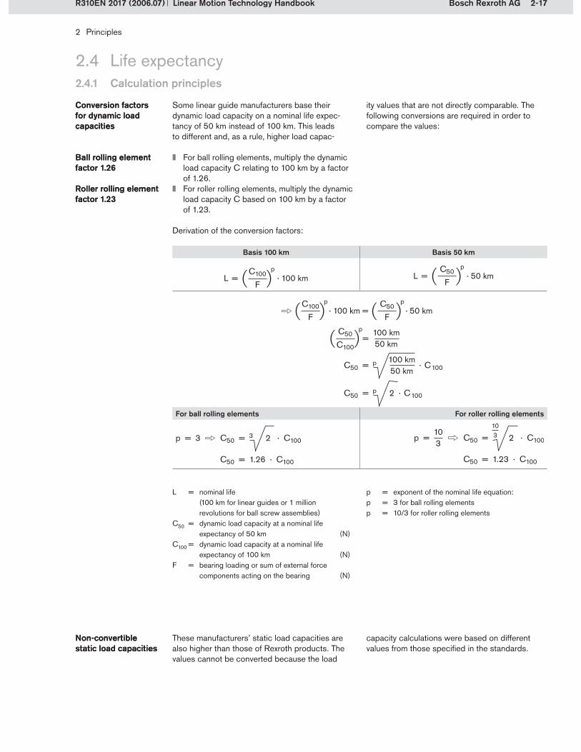
Some linear guide manufacturers base their dynamic load capacity on a nominal life expec-tancy of 50 km instead of 100 km. This leads to different and, as a rule, higher load capac-
Conversion factors for dynamic load capacities
Conversion factors for dynamic load capacities
ity values that are not directly comparable. The following conversions are required in order to compare the values:
For ball rolling elements, multiply the dynamic load capacity C relating to 100 km by a factor of 1.26.For roller rolling elements, multiply the dynamic load capacity C based on 100 km by a factor of 1.23.
Derivation of the conversion factors:
Ball rolling element factor 1.26Ball rolling element factor 1.26
Roller rolling element factor 1.23Roller rolling element factor 1.23
L = nominal life (100 km for linear guides or 1 million
revolutions for ball screw assemblies)C50 = dynamic load capacity at a nominal life
expectancy of 50 km (N)C100 = dynamic load capacity at a nominal life
expectancy of 100 km (N)F = bearing loading or sum of external force
components acting on the bearing (N)
Basis 100 km Basis 50 km
L = · 100 kmC100
F
pL = · 50 km
C50
F
p
C50 = · C100100 km50 km
· 100 km =C100
F
p
=C50
C100
p 100 km50 km
· 50 kmC50
F
p
p
C50 = 2 · C100 p
For ball rolling elements For roller rolling elements
p = 3 C50 = 2 · C100
C50 = 1.26 · C100
3 p = C50 = 2 · C100
C50 = 1.23 · C100
103
103
These manufacturers’ static load capacities are also higher than those of Rexroth products. The values cannot be converted because the load
Non-convertible static load capacitiesNon-convertible static load capacities
capacity calculations were based on different values from those specified in the standards.
p = exponent of the nominal life equation:p = 3 for ball rolling elementsp = 10/3 for roller rolling elements

2-18 Bosch Rexroth AG
2 Principles
Linear Motion Technology Handbook R310EN 2017 (2006.07)
2.4.1 Calculation principlesCalculation principles
2.4 Life expectancyLife expectancy
2.4.1.3 Equivalent load on bearing
A linear motion system is subjected to different types of loading during a travel cycle. In order to simplify life expectancy calculations, these loads are summarized into one single load known as the
The equivalent static load has to be determined when loads from several directions and moments simultaneously act on a linear motion system while it is at rest. The calculation formula for the
Equivalent static loadEquivalent static load
The equivalent dynamic load is determined when loads alternate frequently during operation. Alter-nating loads may, for instance, be positive and negative acceleration forces as well as process forces.
Equivalent dynamic loadEquivalent dynamic load
equivalent load on the bearing. The shorter form “equivalent load” may also be used as a synonym.
The equivalent load comprises two aspects, which are described in more detail in the follow-ing paragraphs:
Equivalent static loadEquivalent dynamic load
Loads summarized in the equivalent load:Loads acting in different directionsLoads acting in different discrete time or travel steps (phases)
equivalent load differs depending upon the de-sign. Please refer to the corresponding details for the individual products.
For calculating the equivalent dynamic load, first of all a representative cycle (cross section) must be established, with the loads, travel distances, speeds and accelerations to be expected. This cycle is divided into n phases in which the loads and speeds are constant. If this is not the case, a mean or equivalent value must be established for the respective phase.
CycleCycle Cycles are distance-dependent for linear motion guides and time-dependent for ball screw drives.A cycle usually consists of a complete travel cycle (forward and back), which is divided into individ-ual time phases.

2-19Bosch Rexroth AG
(2-4)
F (N
)
s (m)
s1 s2
F1
F2
F3
Fm
s3
(2-5)
(2-6)
2 Principles
Linear Motion Technology HandbookR310EN 2017 (2006.07)
2.4.1 Calculation principlesCalculation principles
2.4 Life expectancyLife expectancy
The equivalent dynamic load for a cycle consist-ing of different phases is determined as follows: The respective individual loads are multiplied by the distance covered (expressed as a percentage of total distance covered) in the separate phases and thereby converted to an equivalent load.
Determination of the equivalent dynamic load
Determination of the equivalent dynamic load
p = 3 for linear ball bearingsp = 10/3 for linear roller bearings
When calculating with time phases (discrete time steps), changing velocities and speeds must also be factored in. The procedures for determining cycles and cal-culating discrete travel and time steps are given below.
Calculation of the equivalent dynamic load for linear motion guides:Equivalent dynamic load of linear guides with discrete travel steps
Cycle for phases 1 to 3 with different loads F1 to F3 (simplified illustration without return travel)
Distance-dependent load cycle (example)Distance-dependent cycleDistance-dependent cycle
Determination of the discrete travel steps:The discrete travel steps qsn in percentages per phase are required in order to calculate the equivalent dynamic load on the bearing.
Discrete travel stepsDiscrete travel steps The entire cycle travel s must therefore be divided into phases with discrete travel steps sn. A con-stant load Fn and a constant velocity vn act during each phase.
Calculation of the discrete travel steps:
qsn = discrete travel step in phase n (%)s1 ... sn = travel for phase n (mm)s = travel for all phases (mm)
Fm = equivalent dynamic load (N)F1 ... Fn = load in phase 1 ... n (N)qs1 ... qsn = discrete travel steps for
phases 1 ... n (%)
-- Actual force profile– Approximated force profile– Average force over the entire cycle (equivalent dynamic load Fm)
Fm = F1 · + F2 · + ... + Fn · p qsn
100%qs2
100%qs1
100% p p p
qsn = · 100%sns
2-20 Bosch Rexroth AG
F (N
)
t (s)
t1 t2
F1
F2 F3
Fm
t3
n1 n3
n2
0 1 2 3 4 5 6 7 8 109t (s)
t1 t2 t3250
200
150
100
50
0
n (m
in-1
)
nm
(2-9)
(2-10)
(2-7)
(2-8)
2 Principles
Linear Motion Technology Handbook R310EN 2017 (2006.07)
2.4.1 Calculation principlesCalculation principles
2.4 Life expectancyLife expectancy
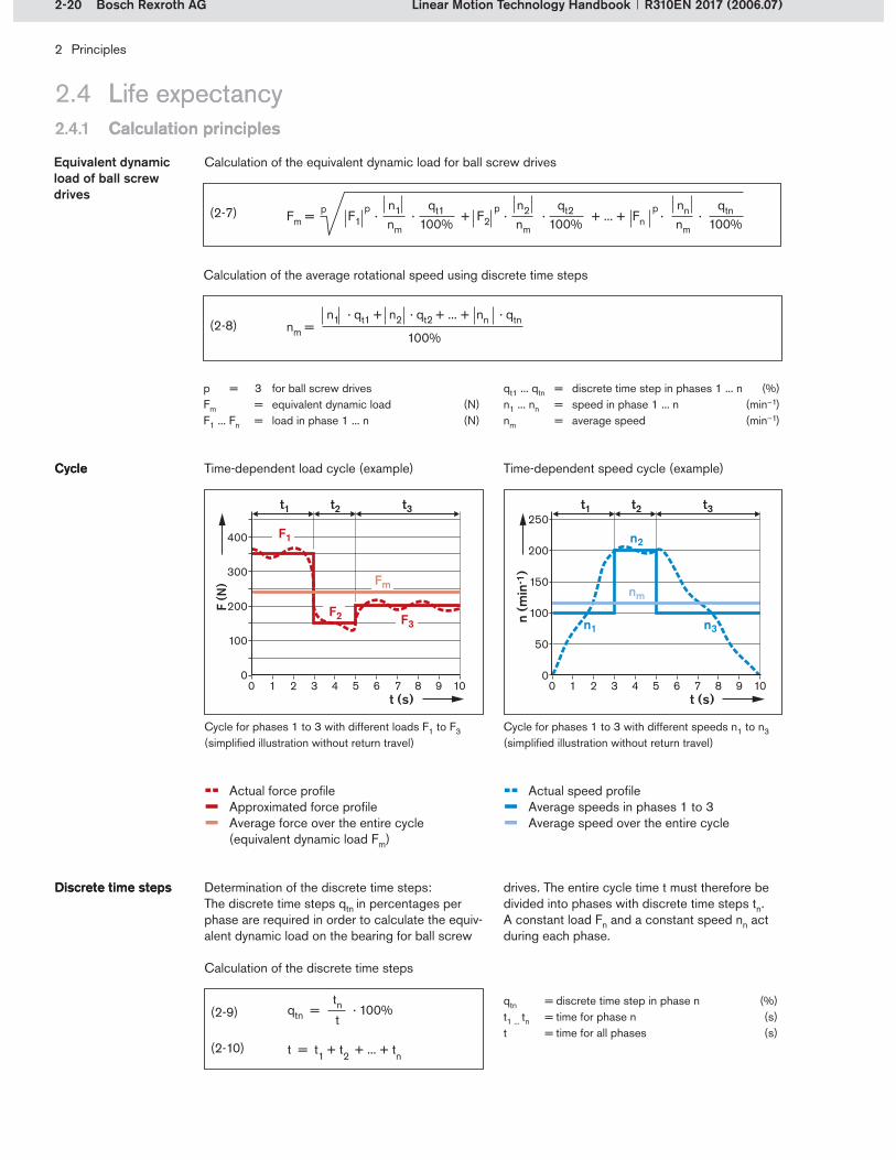
Cycle for phases 1 to 3 with different speeds n1 to n3 (simplified illustration without return travel)
Cycle for phases 1 to 3 with different loads F1 to F3 (simplified illustration without return travel)
Determination of the discrete time steps:The discrete time steps qtn in percentages per phase are required in order to calculate the equiv-alent dynamic load on the bearing for ball screw
Discrete time stepsDiscrete time steps
Calculation of the discrete time steps
qtn = discrete time step in phase n (%)t1 ... tn = time for phase n (s)t = time for all phases (s)
drives. The entire cycle time t must therefore be divided into phases with discrete time steps tn. A constant load Fn and a constant speed nn act during each phase.
Calculation of the equivalent dynamic load for ball screw drives
p = 3 for ball screw drivesFm = equivalent dynamic load (N)F1 ... Fn = load in phase 1 ... n (N)
Equivalent dynamic load of ball screw drives
Calculation of the average rotational speed using discrete time steps
qt1 ... qtn = discrete time step in phases 1 ... n (%)n1 ... nn = speed in phase 1 ... n (min–1)nm = average speed (min–1)
Time-dependent load cycle (example)CycleCycle Time-dependent speed cycle (example)
-- Actual force profile– Approximated force profile– Average force over the entire cycle (equivalent dynamic load Fm)
-- Actual speed profile– Average speeds in phases 1 to 3– Average speed over the entire cycle
qtn = · 100%tnt
n1nm
Fm = F1 · · + F2 · · + ... + Fn · ·p qt1
100%n2nm
qt2100%
nnnm
qtn100%
p p p
nm =n1 · qt1 + n2 · qt2 + ... + nn · qtn
100%

2-21Bosch Rexroth AG
(2-11)
2 Principles
Linear Motion Technology HandbookR310EN 2017 (2006.07)
2.4.1 Calculation principlesCalculation principles
2.4 Life expectancyLife expectancy
2.4.1.4 Static load safety factor
The static load safety factor S0 is required in order to avoid any inpermissible permanent deforma-tions of the running tracks and rolling elements. It is the ratio of the static load capacity C0 to the
Static load safety factor S0
Static load safety factor S0
Conditions of use S0
Normal conditions of use 1 ... 2
Low impact loads and vibrations 2 ... 4
Moderate impact loads and vibrations 3 ... 5
Heavy impact loads and vibrations 4 ... 6
Unknown load parameters 6 ... 15
Normal conditions of use are defined in section 2.4.2.4.
Irrespective of the static load safety factor, it must be ensured that the maximum permissible loads, as indicated for some linear motion guides, are not exceeded.
The load-bearing capability of the threaded connections must also be checked. These are frequently weaker than the bearings themselves. The load-bearing capability of linear motion tech-nology components is such that the screws used could be over-stressed.
S0 = static load safety factorC0 = static load capacity (N)F0 max = load (N)
maximum load occurring, F0 max, and is always determined using the highest amplitude, even if this is only of very short duration.
Recommendations for the static load safety factor under different conditions of use

2-22 Bosch Rexroth AG
2 Principles
Linear Motion Technology Handbook R310EN 2017 (2006.07)
2.4.2 Conditions of use
2.4 Life expectancyLife expectancy
Various conditions affect the life expectancy:
2.4.2.1 Environmental conditions
This is understood as being contamination in the operating environment, such as shavings or dust, which can work its way into the products. This contamination leads to the running tracks and bearing surfaces being subject to greater wear and the nominal life perhaps not being achieved.Coarse contamination with shavings from cutting operations can block the rolling elements, result-ing in running track damage and fracture of the plastic components.The appropriate seals for the degree of contami-nation must be selected.
ContaminationContamination
Influence on service life of the size of any dirt particles working their way into the bearing
Ser
vice
life
Particle size
Contamination
Conditions of use
Metalworking fluids
Temperature
Electrical current
Construction
Humidity
Chemical effects
Environmental conditions
Assembly
Installation conditions
Linear and rotational speeds
Vibrations
Lubrication
Short stroke
Impacts and overloading
Operating conditions

2-23Bosch Rexroth AG
2 Principles
Linear Motion Technology HandbookR310EN 2017 (2006.07)
2.4.2 Conditions of use
2.4 Life expectancyLife expectancy
Metalworking fluids are used in machine tools to cool and lubricate the tool and the workpiece. There are different types of metalworking fluids: non-water-miscible fluids (straight oils), water-miscible fluids (concentrates), and fluids mixed with water (emulsions, solutions).
The guide unit’s lubrication is disturbed by the penetration of metalworking fluid, i.e. the lubricant is altered and gradually washed out. The guide unit must therefore be operated with appropriate protection in place.
Metalworking fluidsMetalworking fluids Aqueous metalworking fluids can also cause corrosion. It has been shown that the water contained in the metalworking fluid evaporates over time and can condense as water on the running tracks and rolling elements. This can lead to premature breakdown because of corroded components.
Preventive measures:Use of corrosion-resistant steel Hard-chroming of the componentsReinforcing the seals on the guidesAdjusting the lubricationExecution of scheduled cleaning and lubricating strokes
When humidity penetrates into the guide units and drive components, corrosion also occurs. The preventive measures are the same as those for protection from metalworking fluids.
HumidityHumidity
There is a permissible operating temperature range for all guide units. The temperature of the elements themselves is ultimately the determin-ing factor, i.e., the incorporated plastic materials, for instance, can lose their mechanical charac-teristics at inadmissible temperature levels. The maximum operating temperatures are shown in the respective product catalogs and in the follow-ing chapters.
When the temperature rises above the upper limit or falls below the lower limit, high stresses can be produced in the components. This can lead to premature system breakdown.
TemperatureTemperature Damage may also be caused as a result of the different heat expansion coefficients of steel and plastic. Plastic deformation, cracking and ruptur-ing of the plastic parts may also lead to premature system breakdown.
When considering the temperature, the whole machine, from bed to attachments, must be taken into account in addition to the linear motion tech-nology components. The different heat expansion coefficients of materials, manufacturing toler-ances and any misalignments and temperature gradients in the construction can produce high additional loads as a result of distortive stresses.
Chemicals can attack the steel and plastic parts of the guide units and/or drive components. The surfaces of the running tracks and the rolling ele-ments are particularly sensitive.
Chemical effectsChemical effects More details of the compatibility of individual chemicals with the guide units can be obtained from Rexroth. If exposure to chemicals cannot be avoided, protective measures must be taken after appropriate consultation with Rexroth.
If electricity flows through the anti-friction bearing elements, this can lead to abrasion and acceler-ated corrosion. Even an amperage within the mA
Electrical currentElectrical current range can cause damage to the rolling contact surfaces. This type of damage to the anti-friction bearing is termed ridge formation or ridging.
2-24 Bosch Rexroth AG
2 Principles
Linear Motion Technology Handbook R310EN 2017 (2006.07)
2.4.2 Conditions of use
2.4 Life expectancyLife expectancy
2.4.2.2 Operating conditions
Insufficient lubrication leads to excessive wear of the running track and rolling element surfaces. Visible signs of this wear include discolorations on the bearing surfaces.
LubricationLubrication The lubrication guidelines and advice (see section 2.5.4 and the product catalogs) must be followed to prevent unnecessary shortening of the service life.
The maximum permissible linear or rotary speed is specified for each product. If these limits are exceeded, the plastic parts in particular can be damaged. All the relevant details for this are pro-vided further on in the chapters on the individual products.
Linear and rotational speedsLinear and rotational speeds
For ball screw drives, resonance, which occurs during operation close to the critical speed, must be avoided because this can destroy the system.
Short-stroke applications are applications in which not all of the rolling elements recirculating within the bearing component arrive in the load-bearing zone during execution of the stroke. The consequences can be premature material fatigue and therefore breakdown of the guide units.
Short strokeShort stroke The definition is different for each product and is discussed in the corresponding sub-chapter and in the product catalogs.Short-stroke applications must be taken into account when calculating the life expectancy.
Vibrations in the machine are caused either by the process (operating forces) or by the drive (regula-tion oscillations and imbalances). Process forces can be, for example, cutting forces in machine tools. Oscillations may be generated by the drive unit when regulating the motor during positioning.
VibrationsVibrations Vibration can lead to contact corrosion, overload-ing and excessive wear in the affected area. The damaged surfaces can greatly reduce the service life of the components.
Brief, jerky loading peaks can adversely affect the life expectancy of the guide units. They are usually caused by cannoning in the machine or collisions of slides and carriages. This causes high stresses in the machine components. This so-called crash behavior is now taken increasingly into consider-ation in new machine designs.
Impacts and overloadingImpacts and overloading
Impacts in the dynamic or static state, whose peak loads are higher than the maximum permis-sible loads can damage the components. Over-loading can cause plastic deformation (e.g. dents in the running tracks as a result of massive forces acting on the rolling elements) or fractures.
2-25Bosch Rexroth AG
2 Principles
Linear Motion Technology HandbookR310EN 2017 (2006.07)
The table in section 2.4.3 contains an illustrated overview of the possible effects of the different influencing factors that can cause damage.
2.4.2 Conditions of use
2.4 Life expectancyLife expectancy
2.4.2.3 Installation conditions
The components may be subject to additional preloading if the dimensions of adjoining struc-tures are outside the permissible tolerances for installation. This increases the internal loading, which shortens the life expectancy. This addition-al loading is often not detectable by increased friction.
ConstructionConstruction The design notes and tolerances indicated in this handbook and the respective product catalogs must therefore be observed.
The same applies to incorrect mounting of the components. This can also cause internal stresses. It is therefore essential to follow the guidelines given in the mounting instructions
MountingMounting and the product catalogs. All mounting and assembly work must be performed with care and due attention to cleanliness.
Rexroth recommends that all guide and drive units be used under normal environmental, oper-ating and installation conditions.
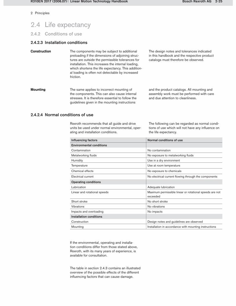
2.4.2.4 Normal conditions of use
The following can be regarded as normal condi-tions of use which will not have any influence on the life expectancy.
Influencing factors Normal conditions of use
Environmental conditions
Contamination No contamination
Metalworking fluids No exposure to metalworking fluids
Humidity Use in a dry environment
Temperature Use at room temperature
Chemical effects No exposure to chemicals
Electrical current No electrical current flowing through the components
Operating conditions
Lubrication Adequate lubrication
Linear and rotational speeds Maximum permissible linear or rotational speeds are not exceeded
Short stroke No short stroke
Vibrations No vibrations
Impacts and overloading No impacts
Installation conditions
Construction Design notes and guidelines are observed
Mounting Installation in accordance with mounting instructions
If the environmental, operating and installa-tion conditions differ from those stated above, Rexroth, with its many years of experience, is available for consultation.

2-26 Bosch Rexroth AG
2 Principles
Linear Motion Technology Handbook R310EN 2017 (2006.07)
2.4 Life expectancy
Damage type Damage photo Possible causes of failure Remedies
Corrosion Unfavorable environmental influencesExposure to metalworking fluidsAggressive media (acids etc.)High humidity (saline mist)
Adapt to suit the environmentUse corrosion-protected versionUse appropriate sealing systemsUse appropriate coversOptimize lubrication
Rolling element blocking
Shavings contaminationDust contaminationInadequate lubricationRolling element fractureDefective recirculation piece
Use appropriate sealing systemsUse appropriate coversEnsure adequate lubricationAvoid overloadingCheck the application
Pronounced darkening
Inadequate lubrication (high temperatures)
Optimize lubrication
PittingPeeling/flaking
Rolling element fatigueEnd of service life
Reduce the loadsUse a heavier duty componentCheck the application
Plastic indentations by rolling elements
Static overload Use a heavier duty componentReduce the loads
Destruction of recirculation zone(e.g. ball runner block)
Excessive speedsCollisionsRolling element blocking because of contamination
Reduce the speedsAvoid overloadingAvoid collisionsUse appropriate sealing systemsUse appropriate covers
2.4.3 Damage profiles
2-27Bosch Rexroth AG
2 Principles
Linear Motion Technology HandbookR310EN 2017 (2006.07)
2.4 Life expectancyLife expectancy2.4.3 Damage profiles
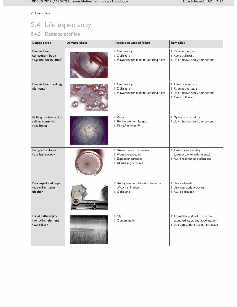
Damage type Damage photo Possible causes of failure Remedies
Destruction of component body(e.g. ball screw drive)
OverloadingCollisionsFlawed material, manufacturing error
Reduce the loadsAvoid collisionsUse a heavier duty component
Destruction of rolling elements
OverloadingCollisionsFlawed material, manufacturing error
Avoid overloadingReduce the loadsUse a heavier duty componentAvoid collisions
Rolling marks on the rolling elements(e.g. balls)
WearRolling element fatigueEnd of service life
Optimize lubricationUse a heavier duty component
Fatigue fractures(e.g. ball screw)
Rotary bending stressesVibration stressesExpansion stressesAlternating stresses
Avoid rotary bending (correct any misalignments)Avoid resonance oscillations
Destroyed end caps(e.g. roller runner blocks)
Rolling element blocking because of contaminationCollisions
Use end sealsUse appropriate coversAvoid collisions
Local flattening of the rolling element(e.g. roller)
SlipContamination
Adjust the preload to suit the expected loads and accelerationsUse appropriate covers and seals

2-28 Bosch Rexroth AG
2 Principles
Linear Motion Technology Handbook R310EN 2017 (2006.07)
2.5.1 Preload and rigidity
2.5 System technology
Preloading increases the rigidity of the overall system. It anticipates the occurrence of elastic deformation of the rolling elements under load, thereby reducing the deflection characteristics of the system as a whole. However, the resistance to movement becomes greater as the preload
PreloadPreload
Effect of preloading on the elastic deflection
– Ball without preload– Ball with preloadpr Deflection at preload force FprFpr Preload force
increases, and high preloads have a negative effect on the life expectancy. When calculating the nominal life, the preload must be taken into account as an additional load on the bearing.
Example:Deformation of a ball between two flat plates, with or without preloading, according to the Hertz theory. Ball diameter = 5 mmPreload force Fpr = 100 N
Elas
tic d
eflec
tion
(m
)
pr
Fpr External load F (N)
The deflection curve for the preloaded ball can be produced by parallel shifting of the curve for the non-preloaded ball.

2-29Bosch Rexroth AG
FN
v
FR
(2-12)
Friction force
2 Principles
Linear Motion Technology HandbookR310EN 2017 (2006.07)
2.5.2 Friction
2.5 System technology
In linear motion technology, the value of the friction coefficient varies according to the system used. The magnitude of the friction force depends primarily on the seals used, the type of rolling
Friction coefficientFriction coefficient
Friction forceFriction force
FR = friction force (N) = friction coefficient (–)FN = normal force (force perpendicular
to the contact area) (N)
contact, and the loading. The lubrication and the speed also affect the friction.
The following table shows the friction coefficients without seals, i.e. the values for rolling friction.
Linear component Friction coefficient without seal Comment
Linear bushing and shaft 0.001 ... 0.004 Standard linear bushing
Ball rail system 0.0020.003
2-point contact4-point contact
Roller rail system 0.0004 Line contact
Ball screw assembly 0.0040.010
2-point contact4-point contact
Using the ball rail system as an example, the chart below illustrates the effects of different seals on the friction force. It shows that the seal friction
Seals and friction forcesSeals and friction forces
accounts for the largest proportion of the overall friction.
Friction forces of a ball runner block with 2% C preload on a guide rail with mounting hole plugs (example)
20%
50%
100%
180%180
160
140
120
100
80
60
40
20
0
Fric
tion
forc
e (%
)
Without seal (only rolling friction)With low-friction sealWith standard seal With standard seal and end seal

2-30 Bosch Rexroth AG
FR
FN
2
3
1
2
1
3
4
2 Principles
Linear Motion Technology Handbook R310EN 2017 (2006.07)
2.5.3 Sealing
2.5 System technologySystem technology
Seals prevent dirt, shavings, etc. from working their way into a system and shortening its service life. There are particular types of seals for special applications. The interaction between the seal and the lubricant is described below.
A particular feature of sealing for linear bearings is that wiper seals are used to seal the ends of the components in the direction of motion. Unlike the seals for rotating rolling contact bearings, there is a discharge of lubricant here. The result-ing lubricating film ensures that there is little wear on the seals.
If side seals are present on the linear motion com-ponents, these work in exactly the same way as antifriction bearing seals in which the inner side of the seal is separated from the (contaminated) outer side.
Function of sealsFunction of seals
End sealsEnd seals
Side sealsSide seals
Wiper end seal of a linear motion guide
Direction of motionInner side of sealContaminationLubricant
FR Friction forceFN Preload force
1�2�3�4�
Seals with very low friction (low-friction seals)Standard sealsSeals with very good sealing action (reinforced seals)
1�2�3�
Res
ista
nce
to m
ovem
ent
Sealing action
The sealing action is influenced by the geometry and material of the seals.The chart opposite shows the effect of different varieties of seal on the sealing action and the resistance to movement.
Sealing actionSealing action
Resistance to movementResistance to movement
Relationship between the sealing action and resistance to movement
Depending on the product, additional sealing elements may be required. Auxiliary seals are to be recommended in environments with fine dirt or metal particles and cooling or cutting fluids.
Additional sealsAdditional seals
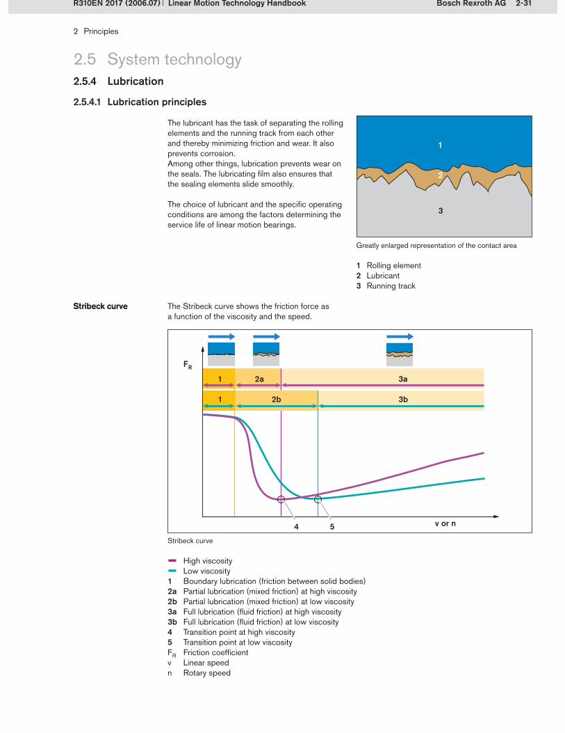
2-31Bosch Rexroth AG
1
2
3
4
2a 3a1
5
FR
2b 3b1
2 Principles
Linear Motion Technology HandbookR310EN 2017 (2006.07)
2.5.4 Lubrication
2.5 System technology
2.5.4.1 Lubrication principles
The lubricant has the task of separating the rolling elements and the running track from each other and thereby minimizing friction and wear. It also prevents corrosion.Among other things, lubrication prevents wear on the seals. The lubricating film also ensures that the sealing elements slide smoothly.
The choice of lubricant and the specific operating conditions are among the factors determining the service life of linear motion bearings.
Greatly enlarged representation of the contact area
Rolling elementLubricantRunning track
1�2�3�
– High viscosity– Low viscosity1 Boundary lubrication (friction between solid bodies)2a Partial lubrication (mixed friction) at high viscosity2b Partial lubrication (mixed friction) at low viscosity3a Full lubrication (fluid friction) at high viscosity3b Full lubrication (fluid friction) at low viscosity4 Transition point at high viscosity5 Transition point at low viscosityFR Friction coefficientv Linear speedn Rotary speed
The Stribeck curve shows the friction force as a function of the viscosity and the speed.
Stribeck curveStribeck curve
Stribeck curve
v or n

2-32 Bosch Rexroth AG
2 Principles
Linear Motion Technology Handbook R310EN 2017 (2006.07)
At standstill, there is contact between the solid bodies, and solid-body friction prevails. The lubri-cating film forms as a function of the speed.
Boundary lubricationBoundary lubrication
Solid-body friction
Mixed friction develops during the starting up or running down phase. A thin lubricating film forms, but there is still partial contact between the solid bodies.
Partial lubricationPartial lubrication
Shortly after the transition point, the optimum condition, fluid friction, is reached. The lubricant’s internal friction now determines the increasing friction coefficient as the speed increases further.
Full lubricationFull lubrication
Viscosity is a measure of the internal friction of lubricating oils (see also section 2.5.4.2). With low-viscosity oils, the partial lubrication range is greater than with high-viscosity oils. The transition point is only reached at a higher speed. Subsequently, the curve does not rise as steeply, since there is less internal friction at lower viscosity.
ViscosityViscosity
Mixed friction
Fluid friction
2.5.4 Lubrication
2.5 System technologySystem technology

2-33Bosch Rexroth AG
2 Principles
Linear Motion Technology HandbookR310EN 2017 (2006.07)
2.5.4 Lubrication
2.5 System technologySystem technology
2.5.4.2 Lubricants
Linear motion components can be lubricated with grease (grease, liquid grease) or oil.
Type NLGI grade Consistency Worked penetration(0.1 mm)
Dynalub
Liquid grease 000 Fluid 445–475
00 Moderately fluid 400–430 Dynalub 520
0 Very soft 355–385
Grease 1 Soft 310–340
2 Moderately soft 265–295 Dynalub 510
3 Semi-fluid 220–250
4 Semi-hard 175–205
5 Hard 130–160
6 Very hard 85–115
Grease lubricants consist of the basic oil (e.g. a mineral oil base), a thickener (e.g. lithium soap) and various additives (e.g. against corrosion). Because of their thick consistency, grease lubri-cants help to prevent the penetration of contami-nants into the linear motion guides and support the action of the sealing and wiping elements.
Grease lubricantsGrease lubricants Greases provide long-lasting lubrication specifi-cally at the contact point between the friction partners and enable very long lubrication intervals up to lubrication for life.
Liquid greases have a soft fluid consistency and can be conveyed much more easily than harder types of grease. They are therefore frequently used in central lubrication systems.
Liquid greaseLiquid grease The central lubrication system’s geometrical char-acteristics must also be taken into account in addition to the consistency class of the grease.
Greases are classified into NLGI grades (National Lubricating Grease Institute) according to their consistency. They are a measure of the lubricant’s stiffness.
Consistency classification of lubricants per DIN 51818:
ConsistencyNLGI gradesConsistencyNLGI grades
Grease lubricants from Rexroth are highlighted in the table. For additional specifications, please refer to the “Recommended grease types” sec-tion below.
Dry lubricants or lubricants containing solid par-ticles should never be used in Rexroth products.

2-34 Bosch Rexroth AG
2 Principles
Linear Motion Technology Handbook R310EN 2017 (2006.07)
2.5.4 Lubrication
2.5 System technologySystem technology
Oil lubricants distribute more evenly than greases and therefore reach the contact points better. They also have a good capacity to dissipate fric-tional heat. However, it must be borne in mind that lubricating oils are dragged out more easily
Oil lubricantsOil lubricants
Grease type Dynalub 510 Dynalub 520
Designation according to DIN 51825according to DIN 51826
KP2K-20GP00K-20
NLGI grade according to DIN 51818 NLGI 2 NLGI 00
Compatibility with any incorporated plastic parts must always be taken into account when using lubricants.
CompatibilityCompatibility
With its Dynalub greases, Rexroth offers lubri-cants specially designed for linear motion guides and ball screw drives:
Recommended grease typesRecommended grease types
Depending on the linear motion product, the re-quired lubricant can be applied using a manually operated grease gun, a lubricant dispenser or an appropriate central lubrication system.Oil-air lubrication or oil-mist lubrication is some-times used for special applications.
Lubricant application methodsLubricant application methods
than grease. Oil lubricants are classified into vari-ous grades, as specified in DIN 51519, according to their viscosity.
Lubricating oil CLP, CGLP per DIN 51517Viscosity ISO VG 220 per DIN 51519Shell Tonna S 220The recommendations in the product catalogs should also be followed.
Recommended oil typesRecommended oil types
Preservative oils for protection against corrosion are not lubricating oils. It is essential to check their compatibility with the lubricant being used.
Preservative oilsPreservative oils
The lubricants used must always be of the same type.
No mixing of lubricantsNo mixing of lubricants
If the equipment is to be used in areas with spe-cial environmental conditions, special testing and possibly a special lubricant may be required.
These environmental conditions are, for instance:Clean roomsVacuumFood industryDirect exposure to metalworking fluids or aggressive chemicalsExtreme temperatures
In these cases please consult Rexroth.
Special environmen-tal conditions

2-35Bosch Rexroth AG
2 Principles
Linear Motion Technology HandbookR310EN 2017 (2006.07)
2.5.4 Lubrication
2.5 System technologySystem technology
2.5.4.3 Lubrication intervals
To ensure that the linear motion components will function perfectly, the prescribed lubrication inter-vals and quantities must be observed.
The initial (basic) lubrication of the linear motion guides and ball screw drives is of particular im-portance. Linear motion components must not be put into operation without initial lubrication. The
Initial lubricationInitial lubrication corresponding product catalogs show the lubri-cation quantities required. If the basic lubrication is applied in-factory before shipment, no initial lubrication by the user is required.
The lubrication intervals and quantities for relu-brication are also shown in the product catalogs. Shorter lubrication intervals may be required in the case of environmental influences such as contamination, the use of metalworking fluids, vibrations, impact loads, etc.
In-service lubricationIn-service lubrication The lubrication intervals are also load-dependent, i.e. the intervals shorten as the loading increases.
Specific recommendations are given in the Lubrication section of the corresponding product catalogs.
Lubrication recommendations from the Roller Rail Systems catalog
The graph shows an example of the load-dependent lubrication intervals for lubrication with grease.
s = relubrication interval expressed as travel (km)C = dynamic load capacity (N)F = equivalent dynamic load (N)
0 0.1 0.2 0.3 0.4F/C
1015
5075
100125
250400
1000
1
s (k
m)
65 + 65/100
100 + 125
55 + 55/85
3525
45

2-36 Bosch Rexroth AG
2 Principles
Linear Motion Technology Handbook R310EN 2017 (2006.07)
2.5.5 Accuracy
2.5 System technologySystem technology
Geometric accuracy is a decisive production and selection criterion in linear motion technol-ogy. The level of accuracy required will depend on the specific application. For optimum results, the level of accuracy to be met must first of all be specified. The higher the level of accuracy
required, the higher the demands will be – both on the linear motion components used and on the overall structure. The various levels of accuracy are defined in different standards.
2.5.5.1 Accuracy levels in guides and drive units
Profiled rail systems, linear bushings and shafts, and ball screw drives are categorized according to accuracy classes or tolerance grades respec-tively.
Profiled rail systems are specified according to accuracy classes. These classes are defined by different levels of maximum tolerances for differences in height and width. They have been standardized in DIN 645 but have been extended
Accuracy classesAccuracy classes
Linear bushings and shafts are specified ac-cording to tolerance grades. These grades are standardized under ISO 13012 and ISO 10285.Ball screw drives are also specified according to tolerance grades. In this case, the tolerance
Tolerance gradesTolerance grades
in the meantime with higher accuracy classes as specified by linear motion guide manufacturers.For more detailed information, see Chapter 3.
2.5.5.2 Accuracy types in linear motion systems
Various types of accuracy are specified for linear motion systems:
Absolute accuracy is the discrepancy between an expected target position and the average value for the actual position, resulting from approaching
Absolute accuracyAbsolute accuracy the target position from different directions (multi-directional motion).
The positioning accuracy is the maximum devia-tion of the actual position from the target position, in accordance with VDI/DGQ 3441.
Positioning accuracyPositioning accuracy Potential influencing factors may be:The accuracy of the linear motion unit, the gearbox, the motor and the measuring systemBall screw pitch errorsThe play in the systemThe controller or its parameter settings
The repeatability indicates how precisely a linear motion system positions itself when approach-ing a position repeatedly from the same direction
RepeatabilityRepeatability (unidirectional motion). Repeatability can also be considered as the deviation of the actual position from the target position.
grades specify the permissible travel deviation and travel variation, as defined in DIN 69051-3.Detailed information is provided in the relevant product catalogs.

2-37Bosch Rexroth AG
2 Principles
Linear Motion Technology HandbookR310EN 2017 (2006.07)
2.6 Product overview
In profiled rail systems, balls, rollers and cam rollers are used as the rolling elements. Because of their high load-bearing capability and their great rigidity they are suitable for almost all tasks requiring precise linear motion. In addition, the guide rails and runner blocks have built-in inter-changeability.This group includes:
Ball Rail SystemsRoller Rail SystemsCam Roller Guides
Detailed information on Profiled Rail Systems can be found in Chapter 3.
Profiled rail systemsProfiled rail systems
Ball rail system
Linear bushings and shafts are rolling-contact linear motion guides. The linear bushings run on hardened and ground precision steel shafts and are available in numerous types, designs and sizes to suit a wide variety of applications. In addition to closed-type linear bushings for self-supporting shafts, open-type bushings are avail-able for high loads and very long guides, with the shaft being supported along its entire length. In comparison to other guides, linear bushings have an additional degree of freedom in the circumfer-ential direction and can compensate for inaccura-cies in the mounting base. Linear bushings and shafts are often referred to as round guides.
Detailed information on Linear Bushings and Shafts can be found in Chapter 4.
Linear bushings and shaftsLinear bushings and shafts
Linear bushing and shaft
Rexroth’s products can be grouped as follows:Profiled Rail SystemsLinear Bushings and ShaftsPrecision Ball Screw AssembliesLinear Motion Systems

2-38 Bosch Rexroth AG
2 Principles
Linear Motion Technology Handbook R310EN 2017 (2006.07)
2.6 Product overview
Ball screw assemblies are rolling-contact drive transmission components for converting rotary motion into linear motion. They operate with a high degree of precision and are suitable for high-speed applications. A broad selection of precision screws and zero-backlash preloaded or adjustable-preload single and double nuts is avail-able for all feed, positioning and transport tasks.
Detailed information on Precision Ball Screw Assemblies can be found in Chapter 5.
Precision ball screw assembliesPrecision ball screw assemblies
Precision ball screw assembly
Linear motion systems are ready-to-install sys-tems which essentially comprise a linear guide unit and a drive unit. All of the systems are also available complete with motor, controller, control system and measuring system.The use of linear motion systems facilitates the design, assembly and commissioning of ma-chines. Individual performance characteristics such as precise movement of loads or fast travel are optimized as necessary for each application. These complete systems provide solutions for a very wide variety of applications.This group includes:
Linear ModulesCompact ModulesLinear Motion Slides
Detailed information on Linear Motion Systems can be found in Chapter 6.
Linear motion systemsLinear motion systems
Linear module

3-1Bosch Rexroth AG
3 Profiled rail systems
Linear Motion Technology HandbookR310EN 2017 (2006.07)
3.1 Principles
Profiled rail systems are the guides of choice for applications requiring especially high precision, low maintenance, low wear and low friction, as well as highly accurate positioning. The Rexroth range includes the following profiled rail systems:
3.1.1 System technology
Product name Abbreviation Section
Ball rail system BRS 3.2
Miniature ball rail system Mini BRS 3.3
eLINE ball rail system eLINE BRS 3.4
Roller rail system RRS 3.5
Cam roller guide CRG 3.6

3-2 Bosch Rexroth AG
1
2
3 4
43
3 Profiled rail systems
Linear Motion Technology Handbook R310EN 2017 (2006.07)
3.1 Principles3.1.1 System technology
3.1.1.1 Structural design of a profiled rail system
Profiled rail system (example: ball rail system)
Profiled rail systems consist of a runner block androfiled rail systems consist of a runner block and a guide rail. The runner block comprises several parts. It has one or more rolling element circuits with a load bearing zone and a return zone. In the load-bearing zone the rolling elements transmit the load from the runner block to the rail, and vice
Runner block and guide railRunner block and guide rail
versa. In the return zone the rolling elements are not subjected to loading and are guided around the circuit and back into the load-bearing zone. This recirculation of the rolling elements allows unlimited linear travel.
Rolling element load-bearing zone and return zone in a schematic representation (left) and as implemented in a ball rail system
Rolling element load-bearing zoneRolling element return zone
3�4�
Guide railRunner block
1�2�

3-3Bosch Rexroth AG
1
23
5
4
6
7
3 Profiled rail systems
Linear Motion Technology HandbookR310EN 2017 (2006.07)
3.1 Principles3.1.1 System technology
A key component of the runner block is the body with its hardened raceways. The rolling elements are normally made from anti-friction bearing steel and are in rolling contact with the runner block and with the rail. The end caps contain recircula-tion pieces which guide the rolling elements from the load-bearing zone to the return zone, and vice versa. The end caps are also designed to
accommodate sealing elements. A complete seal kit consists of the end wiper seals and the side seals, providing all-around sealing to prevent dirt or dust from working its way into the runner block. Runner blocks are lubricated via lube ports in the end caps to ensure full functionality of the guide. The guide rail has hardened running tracks to match the hardened raceways in the runner block.
Lube port (lube nipple)End wiper sealEnd capRunner block bodyRolling elementSide sealGuide rail
1�2�3�4�5�6�7�
Structural design, as illustrated by a latest-generation ball rail system

3-4 Bosch Rexroth AG
3 Profiled rail systems
Linear Motion Technology Handbook R310EN 2017 (2006.07)
Profiled rail guides are available in a wide variety of designs for use as machine elements. The main design styles and sizes are cover-ed
External structure of profiled rail guidesExternal structure of profiled rail guides
Design stylesDesign styles
3.1 Principles3.1.1 System technology
Width of guide rail base
Size is determined by the width A2 of the guide rail base, which also determines the dimensions of the runner block.
In wide profiled rail system designations it is the second figure (e.g. 20/40) which denotes the width A2 of the guide rail base, while the first fig-ure (20/40) refers to the standard sizing system.
SizesSizes
There are, however, many more design styles available than those specified in the standard. Special applications and new machine concepts require specially engineered guides to achieve
Series 1 Series 2 Series 3
Design style Normal Slimline Slimline High
Normal Long
Slimline Long
Slimline High Long
Runner block design styles according to DIN 645-1:
Series 1 Series 2
Design style For mounting from above
For mounting from below
Guide rail design styles according to DIN 645-1:design styles according to DIN 645-1: according to DIN 645-1:
maximum performance. Runner block designs today include wide, short and low-profile versions. Guide rails are also available as V-guide rails with a dovetail fit.
Reference standard DIN 645 Part 2 DIN 645 Part 1
Title of standard Rolling bearings, profile rail rolling guides – Part 2: Dimensions for series 4
Rolling bearings, profile rail rolling guides – Part 1: Dimensions for series 1 to 3
Profiled rail system Miniature Standard
Size 7 9 12 15 15 20 25 30 35 45 55 65
by the DIN 645 standard, which also specifies the main outside dimensions and the connection dimensions.
No reference standard
Profiled rail system Wide Heavy duty
Size 20/40 25/70 35/90 55/85 65/100 100 125

3-5Bosch Rexroth AG
xy
z
5
31
4
2
4 6
3 Profiled rail systems
Linear Motion Technology HandbookR310EN 2017 (2006.07)
3.1 Principles3.1.1 System technology
Axial and rotational directions of movement
Because of their structural design, linear guides have various reference surfaces and edges for alignment with and mounting to adjoining struc-tures. The bases of the runner blocks and guide rails serve as mating surfaces for mounting to the surrounding structure. They have threaded or countersunk holes to receive fixing screws.
The side surfaces serve to transmit forces laterally and to align the components during installation. They are called reference edges. The guide rail has two reference edges that can be used inde-pendently of each other. Runner blocks generally have one reference edge which must be taken into consideration during mounting. However, some runner block types can have two or more reference edges.
Reference surfaces and edgesReference surfaces and edges
Reference surfaces and edges
Base of the runner blockHead of runner blockReference edge on the runner blockTwo reference edges on the railHead of the guide railBase of the guide rail
1�2�3�4�5�6�
In profiled rail guides, movement or displacement of the runner block is governed by the coordinate system shown in the illustration. This coordinate system has 6 degrees of freedom. The X-axis is the direction of travel. In all other directions, movement is only possible as elastic deflection of the guide unit under load.
Linear degrees of freedom (along the axes):Direction of travel (X-axis)Lateral movement (Y-axis)Lift-off movement (Z-axis) Downward movement (Z-axis, negative direction)
Rotational degrees of freedom:Rolling (rotation about the X-axis)Pitching (rotation about the Y-axis)Yawing (rotation about the Z-axis)
Coordinate systemCoordinate system
Rolling
Yawing
Pitching

3-6 Bosch Rexroth AG
3 Profiled rail systems
Linear Motion Technology Handbook R310EN 2017 (2006.07)
Just as in rotary rolling contact bearings, the raceways in profiled rail guides can be arranged in an X- or an O-configuration. The system char-acteristics of these two arrangements are identi-cal except for their behavior when subjected to a torsional moment. They show no differences in behavior under down loads, lift-off loads and side loads or under longitudinal moments.
Comparison of X- and O-arrangementsComparison of X- and O-arrangements
X-arrangement O-arrangement
Because of its greater leverage (a), the O-arrange-ment can withstand higher torque forces than the X-arrangement. In same-size systems, the O-arrangement therefore offers higher torsional stiffness. Rexroth’s 4-row ball and roller rail sys-tems have an O-arrangement.
3.1 Principles3.1.1 System technology
Manufacturers are free to design the internal structure of profiled rail guides as they wish. The guides produced by the various manufacturers differ in the way rolling contact is achieved. Specifically, these differences relate to:
Rolling element shape (ball/roller)Rolling element sizeRolling contact type (2-point/4-point)Conformity of ball contactNumber of rolling element rows (2/4/6)Arrangement of rolling element rows (X/O) Contact angle
Internal structure of profiled rail guidesInternal structure of profiled rail guides
These differences result in different system characteristics in terms of the load capacity, rigidity and friction.
The influences of the rolling element shape and size, rolling contact and conformity were discussed earlier in Chapter 2, section 2.3. This section therefore deals only with the specific characteristics of profiled rail guides.
The number of load-bearing rolling element rows is a basic distinguishing feature in profiled rail guides. It influences the load capacity, the rigidity behavior and the friction behavior of the profiled rail guide. The more rows a rail guide has, the greater the load capacity and the rigidity will be. However, this statement applies only when all other parameters remain constant, i.e. same roll-ing element shape and size, same type of rolling contact (2-point or 4-point), same conformity, same arrangement, and same contact angle.
Number of rolling element rowsNumber of rolling element rows
2 rolling element rows 4 rolling element rows 6 rolling element rows
It should also be noted that increasing numbers of rows result in increasingly complex and costly designs.
Rexroth uses only 2-row and 4-row designs in its ball rail systems. The roller rail systems have 4 rows. These designs allow a much more even distribution of the load across the rolling element rows than is possible with 6-row profiled rail guides.
a a

3-7Bosch Rexroth AG
!
! !
! !
Fz
!
!
!
! Fy
3 Profiled rail systems
Linear Motion Technology HandbookR310EN 2017 (2006.07)
3.1 Principles3.1.1 System technology
Profiled rail guides should be capable of taking up loads from all directions. The raceways or contact points are therefore arranged at an angle. This corresponds to the nominal contact angle as defined in the ISO 14728 standard for the angle of contact between the rolling-contact partners in profiled rail guides.
ISO 14728 defines the nominal contact angle as follows:“Angle between the direction of load on the linear bearing and the nominal line of action of the re-sultant forces transmitted by a bearing raceway member to a rolling element.”
The contact angle is therefore dependent on the direction of loading. It is always indicated for loads in the main directions of loading (Y-axis, Z-axis). In all Rexroth profiled rail systems, the contact angle is 45°.
Contact angleContact angle
Nominal contact angle
Contact angle under side loadsContact angle under lift-off or down loads

3-8 Bosch Rexroth AG
3 Profiled rail systems
Linear Motion Technology Handbook R310EN 2017 (2006.07)
3.1 Principles
Rolling-bearing profiled rail guides can be differentiated according to the following basic structural criteria.
Number and arrange-ment of rolling element rows
Number and arrange-ment of rolling element rows
3.1.1 System technology
Profiled rail guide Number of rolling element rows
Schematic representation
Type of contact Arrangement of raceways
Rexrothrange
Ball rail systems (BRS)
2 rows 4-point contact Miniature ball rail systemseLINE ball rail systems
4 rows 4-point contact
4 rows 2-point contact X-arrangement
4 rows 2-point contact O-arrangement Ball rail systems
6 rows 4-point contact
6 rows 2-point contact Combined X-O-arrangement
Roller rail systems (RRS)
4 rows Line contact X-arrangement
4 rows Line contact O-arrangement Roller rail systems

3-9Bosch Rexroth AG
xy
z
Mx
M z
My
Fz
Fy
3 Profiled rail systems
Linear Motion Technology HandbookR310EN 2017 (2006.07)
3.1 Principles
3.1.1.2 Load-bearing capability
In Rexroth’s 2-row and 4-row ball and roller rail systems the raceways are arranged with a 45° angle of contact in relation to the main di-rections of loading. This results in the same high load capacity of the entire system in all four major planes of load application. The runner blocks can be subjected to forces and to load moments.
Forces in the four major planes of load application:Lift-off Fz (positive Z-direction)Down load –Fz (negative Z-direction)Side load Fy (positive Y-direction)Side load –Fy (negative Y-direction)
Moment loads:Moment Mx (about the X-axis)Moment My (about the Y-axis)Moment Mz (about the Z-axis)
Load-bearing capabilityLoad-bearing capability
3.1.1 System technology
Major directions of loading
The load-bearing capability of profiled rail systems is described by the static load capacity C0 and the dynamic load capacity C. These load capac-ity ratings are key characteristics describing the performance capability of the systems. Rexroth verifies the dynamic load capacities for all of
Load capacitiesLoad capacities
The radial loading of constant magnitude and direction which a linear rolling bearing can
Definition of dynamic load capacity CDefinition of dynamic load capacity C
its products in endurance tests. Its profiled rail systems have the same load capacities in all major planes of load application. The methods for calculating load capacities are defined in the ISO 14728 standard.
The static load in the direction of loading which results in a permanent overall deformation of approximately 0.0001 times the rolling element diameter at the center of the most heavily load- ed rolling element/raceway contact (acc. to ISO 14728-2).
Definition of static load capacity C0
Definition of static load capacity C0
According to ISO 14728-2, this corresponds to a calculated contact stress at the contact point of:
4200 to 4600 MPa for ball rail guides4000 MPa for roller rail guides
The dynamic load moments Mt and ML and the static load moments Mt0 and ML0 are calculated from the load capacities, the geometry, the num-ber of rolling element rows, the number of load-carrying rolling elements, and the contact angle.
Dynamic load mo-ments Mt, ML and static load moments Mt0, ML0
Dynamic load mo-ments Mt, ML and static load moments Mt0, ML0
They are crucial factors when the runner blocks are subjected to torsional and longitudinal mo-ment loads.
theoretically endure for a nominal life of 100 km distance traveled (acc. to ISO 14728-1).
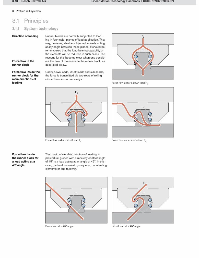
3-10 Bosch Rexroth AG
3 Profiled rail systems
Linear Motion Technology Handbook R310EN 2017 (2006.07)
3.1 Principles3.1.1 System technology
Runner blocks are normally subjected to load-ing in four major planes of load application. They may, however, also be subjected to loads acting at any angle between these planes. It should be remembered that the load-bearing capability of the elements will be reduced in such cases. The reasons for this become clear when one consid-ers the flow of forces inside the runner block, as described below.
Under down loads, lift-off loads and side loads, the force is transmitted via two rows of rolling elements or via two raceways.
Force flow in the runner blockForce flow in the runner block
Direction of loadingDirection of loading
Force flow inside the runner block for the main directions of loading
Force flow inside the runner block for the main directions of loading Force flow under a down load Fz
The most unfavorable direction of loading in profiled rail guides with a raceway contact angle of 45° is a load acting at an angle of 45°. In this case, the load is carried by only one row of rolling elements or one raceway.
Force flow inside the runner block for a load acting at a 45° angle
Force flow inside the runner block for a load acting at a 45° angle
Lift-off load at a 45° angleDown load at a 45° angle
Force flow under a lift-off load Fz Force flow under a side load Fy

3-11Bosch Rexroth AG
F
Fz
Fcomb
Fy
3 Profiled rail systems
Linear Motion Technology HandbookR310EN 2017 (2006.07)
3.1 Principles3.1.1 System technology
Since the reference edges and the mounting surfaces can only transmit vertical and horizontal forces, the most unfavorable case occurs when the loads acting in the vertical and horizontal direction are of equal magnitude.
Combined equivalent load on bearingCombined equivalent load on bearing
Most unfavorable case: Load acting at an angle of 45° or horizontal and vertical loads of equal magnitude
Expressed in mathematical terms, the resultant total load is obtained by addition of the vertical force vector and the horizontal force vector :
The load-bearing capacity of the profiled rail guide depends on the direction of loading. For the nominal life calculation, the factor used to describe the load is therefore not the resultant load but instead the combined equivalent load on the bearing Fcomb . This is obtained by adding the absolute values of the vertical force |Fz| and the horizontal force |Fy| acting on the run-ner block.
(3-1)
Calculating the combined equivalent load on the bearing thus makes allowance for the fact that the load-bearing capability of a profiled rail guide will be reduced when a load is applied at an angle rather than in one of the main directions of loading. For the same load capacity rating, the life expectancy will therefore be shortened due to the higher load on the bearing.
The structural design of Rexroth’s profiled rail systems permits a simplified calculation of the combined equivalent load on the bearing Fcomb using formula (3-1).
If a single load or the load resulting from sev-eral forces acts in any direction other than the main directions of loading, then the calculated combined load on the bearing Fcomb will be greater than the resultant total load | | obtained by addition of the force vectors.
Comparison of | | and Fcomb for the most unfavorable case |Fy| = |Fz|
Fres
Fy
Fz
Determination of Fcomb

3-12 Bosch Rexroth AG
3 Profiled rail systems
Linear Motion Technology Handbook R310EN 2017 (2006.07)
3.1 Principles3.1.1 System technology
The following diagram maps the direction of load-ing relative to the load or the load capacity, show-ing the conditions under which the same nominal life will be achieved. The values derive from the
Dependency of nominal life on the direction of loading
Dependency of nominal life on the direction of loading
Loads and load capacities for the same nominal life under different directions of loading
– Load– Load capacity
(3-2)
formulas mentioned above for calculating the load on the bearing and the relationship between the load capacity and the load.
a) In all four major directions of loading the value is 1, i.e. the full nominal life will be achieved at loads and load capacities of 100%.
b) To achieve the same nominal life as in one of the four main directions of loading, a load acting at a 45° angle must not exceed 0.707 times the load acting in one of the four main directions of loading.
Notes explaining the diagram Notes explaining the diagram
c) Alternatively, to achieve the same nominal life as in one of the four main directions of loading, the load capacity for a load acting at a 45° an-gle would have to be 1.414 times greater than the load capacity in the main directions of loading. In practice, this means installing a larger profiled rail guide or a greater number of runner blocks in order to increase the load-bearing capability of the system.
L = nominal life (km)C = load capacity (N)F = load (N)
45
90
135
180
225
270
315
0
0
0.5
1.0
1.5
c)a)
b)

3-13Bosch Rexroth AG
L = · 105 m CF
p
3 Profiled rail systems
Linear Motion Technology HandbookR310EN 2017 (2006.07)
3.1 Principles3.1.1 System technology
To increase the service life of the guides, they should therefore be installed in an orientation appropriate to the actual direction of loading. If this is not done, the service life may be drasti-cally shortened.
Since the load capacity to load ratio is accounted for in the nominal life calculation by the expo-nent p, the travel life expectancy will therefore be significantly reduced at a load application angle of 45°.
Effect of the load direction on the life expectancy (in %)
– Ball rail system– Roller rail system
(3-3)
Example:For a load acting at an angle of 45°, the life ex-pectancy of a ball rail system is only 35% of that for a load acting in any of the main loading direc-tions. The life expectancy of a roller rail system may even be as little as 32%.
p = 3 for ball rail guidesp = 10/3 for roller rail guides
45
90
135
180
225
270
315
0
0 %10%20%30%40%50%60%70%80%90%
100%

3-14 Bosch Rexroth AG
a a
DWDW
3 Profiled rail systems
Linear Motion Technology Handbook R310EN 2017 (2006.07)
3.1 Principles3.1.1 System technology
Runner blocks can be preloaded in order to increase the overall rigidity of the profiled rail guide. The preload anticipates the effects of elastic deflection. It is achieved through widening of the runner block body by using rolling elements (diameter DW) with a defined oversize dOS.
Definition of preloadDefinition of preload
Preloading by inserting oversized rolling elements
The chosen oversize determines the degree of preload. Preloading causes the flanks of the runner block body to curve outward at the tips. Depending on the linear guide type, versions are available with different degrees of preload or with-out preload (i.e., with clearance).
3.1.1.3 Preload
DW = rolling element diameter (mm)a = distance between raceways (mm)dOS = oversize (mm)
DW = a + dOS

3-15Bosch Rexroth AG
3 Profiled rail systems
Linear Motion Technology HandbookR310EN 2017 (2006.07)
3.1 Principles3.1.1 System technology
Example for a size 25 runner block with a load capacity C of 22,800 N and preload class C2:
Fpr = Xpr · C = 0.08 · 22800 N = 1824 N
(3-4)
Fpr = preload force of the runner block (N)Xpr = preload class factor (–)C = dynamic load capacity of the runner block (N)
The preload force for a particular preload class can be calculated using the respective preload class factor Xpr . This internal loading of the runner block must be taken into account when calculat-ing the life expectancy.
Preload class Code
Version Preload class factor Xpr (–)
Application area
C0 Without preload (with clearance)
0 For particularly smooth-running guide systems with the lowest possible friction and a minimum of external influences.
C1 Slight preload 0.02 C (2% of C)For roller rail systems (RRS):0.03 C (3% of C)
0.02
0.03 (RRS)
For zero-clearance guide systems with low external loads and low requirements on overall rigidity.
C2 Medium preload 0.08 C (8% of C)
0.08 For precise guide systems with both high exter-nal loading and high demands on overall rigidity; also recommended for single-rail systems. Above-average moment loads can be absorbed without significant elastic deflection.
C3 High preload 0.13 C (13% of C)
0.13 For highly rigid guide systems such as required in precision machine tools or forming/molding machines. Above-average loads and moments can be absorbed with the least possible elastic deflection.
Selection of the preload classSelection of the preload class
The degree of preload is classified in relation to the dynamic load capacity C. Depending on their design, runner blocks may be available in up to four preload classes (C0, C1, C2, C3).
Preload classesPreload classes The higher the preload, the more rigid the runner block will be.

3-16 Bosch Rexroth AG
3 Profiled rail systems
Linear Motion Technology Handbook R310EN 2017 (2006.07)
3.1 Principles3.1.1 System technology
The rigidity of a runner block is defined by the relationship between the external load and the resulting elastic deflection in the direction of loading.
Rigidity is an important criterion for selection of rail guides. Profiled rail systems have different rigidity levels (see selection criteria, section 3.1.2)
Definition of rigidityDefinition of rigidity
3.1.1.4 Rigidity
(3-5)
(3-6)
(3-7)
according to their type and design. The rigidity of a particular runner block depends on the preload class selected. The higher the preload of the system, the greater the rigidity will be. The rigid-ity levels of the runner blocks are illustrated as curves in charts (see example on following page).
Down load
Lift-off load
Side load
F = load resulting from a force (N) = elastic deflection in the
direction of loading (m) c = rigidity in the direction of loading (N/m)
cdown =Fdown
down
clift-off =Flift-off
lift-off
cside =Fside
side
Fdowndown
Flift-offlift-off
Fsideside
Downward load
Upward load
Sideways load
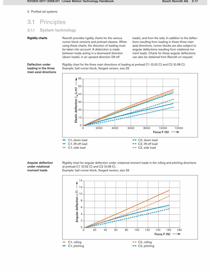
3-17Bosch Rexroth AG
3 Profiled rail systems
Linear Motion Technology HandbookR310EN 2017 (2006.07)
3.1 Principles3.1.1 System technology
Rexroth provides rigidity charts for the various runner block versions and preload classes. When using these charts, the direction of loading must be taken into account. A distinction is made between loads acting in a downward direction (down loads), in an upward direction (lift-off
Rigidity chartsRigidity charts loads), and from the side. In addition to the deflec-tions resulting from loading in these three main axial directions, runner blocks are also subject to angular deflections resulting from rotational mo-ment loads. Charts for these angular deflections can also be obtained from Rexroth on request.
Rigidity chart for the three main directions of loading at preload C1 (0.02 C) and C2 (0.08 C). Example: ball runner block, flanged version, size 25
Deflection under loading in the three main axial directions
Angular deflection under rotational moment loads
Rigidity chart for angular deflection under rotational moment loads in the rolling and pitching directions at preload C1 (0.02 C) and C2 (0.08 C). Example: ball runner block, flanged version, size 25
– C1, down load – C1, lift-off load– C1, side load
-- C2, down load-- C2, lift-off load-- C2, side load
– C1, rolling – C1, pitching
-- C2, rolling -- C2, pitching
Elas
tic d
eflec
tion e
l (m
)
Force F (N)
Force F (N)
Ang
ular
defl
ectio
n
(')
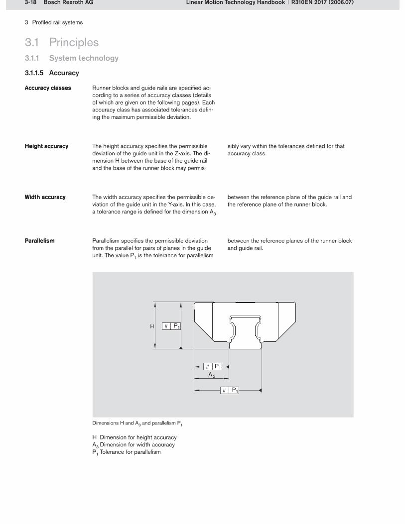
3-18 Bosch Rexroth AG
H P1
P1
P1
A3
3 Profiled rail systems
Linear Motion Technology Handbook R310EN 2017 (2006.07)
3.1 Principles3.1.1 System technology
3.1.1.5 Accuracy
Runner blocks and guide rails are specified ac-cording to a series of accuracy classes (details of which are given on the following pages). Each accuracy class has associated tolerances defin-ing the maximum permissible deviation.
Accuracy classesAccuracy classes
The height accuracy specifies the permissible deviation of the guide unit in the Z-axis. The di-mension H between the base of the guide rail and the base of the runner block may permis-
Height accuracyHeight accuracy
H Dimension for height accuracyA3 Dimension for width accuracyP1 Tolerance for parallelism
sibly vary within the tolerances defined for that accuracy class.
The width accuracy specifies the permissible de-viation of the guide unit in the Y-axis. In this case, a tolerance range is defined for the dimension A3
Width accuracyWidth accuracy between the reference plane of the guide rail and the reference plane of the runner block.
Dimensions H and A3 and parallelism P1
Parallelism specifies the permissible deviation from the parallel for pairs of planes in the guide unit. The value P1 is the tolerance for parallelism
ParallelismParallelism between the reference planes of the runner block and guide rail.

3-19Bosch Rexroth AG
3 Profiled rail systems
Linear Motion Technology HandbookR310EN 2017 (2006.07)
3.1 Principles3.1.1 System technology
The height and width accuracies are specified by tolerances for the dimensions H and A3 as defined for the various accuracy classes. The accuracy tolerances relate to the manufacturing tolerances of the runner block and the guide rail.
Tolerances for accuracy classesTolerances for accuracy classes
Accuracy classes Tolerances1) for dimensions H and A3 (m) Max. difference in dimension H and A3 on one guide rail (m)
H,
A3
H A3
E ± 120 ± 70 60
N ± 100 ± 40 30
H ± 40 ± 20 15
P ± 20 ± 10 7
XP2) ± 11 ± 8 7
SP ± 10 ± 7 5
UP ± 5 ± 5 3
Measured at middle of runner block
For any runner block/rail combination at any position on rail
For different runner blocks at same position on rail
Tolerances for combinations of guide rails and runner blocks with different accuracy classes on requestCombination of XP runner block and SP guide rail in ball rail systems
1)2)
The table below shows the height and width tolerances for profiled rail systems.
The parallelism offset relates to the manufactur-ing tolerances of the guide rails. The graph below shows the maximum parallelism offset P1 when the rail guide is in service as a function of the
Parallelism offset of the rail guide in service
Parallelism offset of the rail guide in service
Maximum permissible parallelism offset P1 of the rail guide in service (measured at middle of runner block) as a function of the guide rail length L
guide rail length. These curves assume that the respective rail guides have been mounted under ideal conditions.

3-20 Bosch Rexroth AG
3 Profiled rail systems
Linear Motion Technology Handbook R310EN 2017 (2006.07)
The guide components are manufactured with such high precision that runner blocks and guide rails can be interchanged without problems. For example, a runner block can be paired with any
Precision manufacturingPrecision manufacturing
guide rail of the same size. Similarly, different runner blocks can also be used on one and the same guide rail. Runner blocks can therefore be ordered separately and combined as required.
3.1 Principles3.1.1 System technology
The accuracy classes define the geometric toler-ances (i.e. maximum permissible deviations) for rail guides in the directions described above. The original accuracy classes were first specified in DIN 645. Advances in manufacturing techniques
Accuracy classesAccuracy classes have made it possible to add higher accuracy classes to the ones defined in the standard. The accuracy class for a profiled rail system is se-lected on the basis of the intended application.
Profiled rail guide Accuracy class and description
E N H P XP SP UPeLINE Normal High
accuracyPrecision eXtra
precisionSuper precision
Ultra precision
Ball rail system
–
Miniature ball rail system
– – – –
eLINE ball rail system
– – – – –
Roller rail system
– – –
Accuracy class XP applies only to high-precision ball runner blocks with very good travel character-istics. Guide rails are not available in XP.Accuracy classes XP, SP and UP are suitable for high-precision metal-cutting operations, measur-ing technology, high-precision scanners, electrical discharge machining, etc.
In roller rail systems, guide rails can also be sup-plied in accuracy class GP (corresponds to SP, but with additional sorting according to height tol-erance). Cam roller guides have fixed tolerances.
Accuracy classes of Rexroth profiled rail systems:

3-21Bosch Rexroth AG
xy
z
3 Profiled rail systems
Linear Motion Technology HandbookR310EN 2017 (2006.07)
3.1 Principles3.1.1 System technology
For a system with several runner blocks spaced at short distances, it is advisable to select a higher accuracy class for the run-ner blocks than for the guide rail. The runner block tolerances are the deciding factor here, because a configuration with multiple runner blocks may result in preloading of the system.
Selection of the accuracy classSelection of the accuracy class
If the runner blocks are spaced widely apart, the guide rail should have a higher accuracy class than the runner blocks. In this case, the guide rail tolerances are more important because of possible distortive stresses, es-pecially in systems with several rails installed parallel to one another.
Recommended combination Guide rail accuracy classes
E N H P SP UP
Runner block accuracy classes
E – – – –
N – – –
H – – –
P – – –
XP – – –
SP – – –
UP – – – –
Table showing recommended runner block/guide rail combinations:
The table below allows preselection according to application areas:
Accuracy classes Application area Accuracy
Handling Forming operations
Cutting operations
Measuring, testing
E eLINE – – – Low demands on accuracy
N Normal – – –
H High accuracy
P Precision –
XP eXtra precision –
SP Super precision – –
UP Ultra precision – – Extremely high demands on accuracy
The travel accuracy of profiled rail systems is described by five of the six possible degrees of freedom. These are the linear degrees of freedom in the Y-axis (width variations) and in the Z-axis (height variations), as well as the rotational degrees of freedom about the X-axis (rolling), Y-axis (pitching) and the Z-axis (yawing). Since the X-axis is the direction in which the guide trav-els, no accuracy specifications can be made here.
Five degrees of freedomFive degrees of freedom
3.1.1.6 Travel accuracy
Axial and rotational directions of movement
Rolling
Yawing
Pitching

3-22 Bosch Rexroth AG
!µ
3 Profiled rail systems
Linear Motion Technology Handbook R310EN 2017 (2006.07)
Geometric travel accuracy is the term used to de-scribe the actual travel performance of the runner block when in service.
The movement of the rolling elements as they re-circulate influences the geometric travel accuracy of the profiled rail system as a whole. A particular phenomenon in this respect is rolling element pulsation. This arises as a result of changes in load distribution as the rolling elements enter the load-bearing zone and the related variation in the
Travel accuracy accuracyTravel accuracy accuracy
Comparison of height variations between a conventional ball runner block (–) and a high-precision ball runner block (–). Example: size 35, ball diameter 6.35 mm
number of rolling elements actually bearing the load. Geometric travel variations due to rolling element pulsation are characterized by the period length of the variations, which is equivalent to two times the rolling element diameter. The geometry of the entry and exit zones guiding the rolling elements into and out of load-bearing zone has a major effect on rolling element pulsation.
The guide rail also has an influence on geometric travel accuracy. In addition to effects due to the height and width variations described in con-nection with tolerance classes, screw-fastening of the guide rail can cause local deformations around the mounting holes spaced along the rail. This results in vertical waviness. Horizontal wavi-ness may also occur due to straightness errors in the guide rail, improper mounting, and geometric deficiencies in the adjoining structure.
All of these factors combined – accuracy of the surrounding structures, installation, and the rail and rolling elements themselves – result in geo-metric travel variations causing the runner block to execute micromovements as it travels along the rail. These micromovements occur both in the rotational degrees of freedom (rolling, pitching, yawing) and in the linear degrees of freedom (height and width variations).
= height variation (m)s = travel (mm)
3.1 Principles3.1.1 System technology
Variations in the Z-axis
Vertical and horizontal waviness
Ball runner blocks are available in high-precision versions with optimized geometry at the transi-tions between the load-bearing and the return
High precision versionsHigh precision versions
zone, resulting in especially good travel perfor-mance. This optimized geometry is a standard feature in the XP, SP and UP versions.

3-23Bosch Rexroth AG
4
3
1
2
5
1
2
67
3
3 Profiled rail systems
Linear Motion Technology HandbookR310EN 2017 (2006.07)
3.1 Principles3.1.1 System technology
The following measures have a positive effect on the geometric travel performance of profiled rail systems:
Use of high-precision runner blocksUse of runner blocks and guide rails with high accuracy classes Use of long runner blocksReducing the tightening torque for the rail mounting screws. Caution: This may result in a decrease in the transmittable forces and moments.Reducing the spacing between guide rail mounting holes in ball rail systems for applica-tions requiring high travel accuracy and low variations in frictional drag
Optimizing the travel accuracyOptimizing the travel accuracy
Installing systems with two rails and at least two runner blocks per railUse of wide runner blocks in systems with only one guide rail
Very high travel accuracy can be achieved only if the adjoining structure has been manufactured to close shape and location tolerances and with accurately machined surfaces. Data on the required tolerances can be obtained from Rexroth on request.
A ball deflects the steel segment only as far as necessary to allow the following ball to enter load-free. The ball is no longer guided into the load-bearing zone by a rigid entry channel but by a very smooth flexing curve, which ideally transi-tions tangentially into the load-bearing zone.
The extremely smooth ball entry behavior and the continuous adjustment of the entry zone in response to the actual load are the great advan-tages of these high precision ball runner blocks.
The balls are guided to the beginning of the entry zone by the ball recirculation track.When the distance between the runner block and the rail becomes smaller than the ball diameter, the ball is subjected to loading (preload).The preload increases in the entry zone and reaches a maximum in the load-bearing zone. The ball transmits the force from the runner block to the rail.As they transition from the entry zone into the load-bearing zone the balls are subjected to pulse-like changes in loading due to the changes in geometry.
Entry zone geometry of conventional ball runner blocks
Entry zone geometry of conventional ball runner blocks
The balls are guided to the beginning of the entry zone by the ball recirculation track. The ball (5) is not loaded as it enters the tran-sition zone because the ball (6) causes the tip of the steel segment (4) to deflect. This deflec-tion is the sum of the compliance of the ball itself and the compliance of the unsupported end of the steel segment.As the distance between the steel segment and the rail becomes smaller than the ball diameter, the ball is gradually subjected to loading.The preload is smoothly increased until the ball (7) has reached its maximum preload.
Entry zone geometry of high-precision ball runner blocks
Entry zone geometry of high-precision ball runner blocks
Entry zone in conventional runner blocks
Runner blockRolling elementGuide rail
1�2�3�
Entry zone in high-precision runner blocks
Runner blockRolling elementGuide railSteel segment
1�2�3�4�

3-24 Bosch Rexroth AG
FRFRFRFRFRFRFRFRFRFR
FRFRFF v
FR (N
)
s (mm)
3 Profiled rail systems
Linear Motion Technology Handbook R310EN 2017 (2006.07)
3.1 Principles3.1.1 System technology
When dimensioning the drive, it is essential to know the level of friction involved. Friction mea-surements are therefore carried out on all profiled rail systems. The friction values are given in tables in the respective product catalogs. Friction data for special applications can be obtained from Rexroth on request.
The frictional drag of a runner block may vary as it travels along the rail. This is due to the varying number of rolling elements present in the load-bearing zone at any one time. Alternate loading and unloading of the rolling elements as they enter into and exit from the load-bearing zone also causes variations.
Friction in profiled rail guidesFriction in profiled rail guides
3.1.1.7 Friction
Frictional force FR
Friction profile of a conventional ball runner block (–) and of a high-precision ball runner block (–) under the same load. Example: size 35, ball diameter 6.35 mm
The level of friction in a specific profiled rail sys-tem depends on the following factors:
LoadPreloadSealing
FR = friction force (N)s = travel (mm)
Travel speedLubricantRunner block temperature
The total friction of a runner block is determined by several factors:
Rolling frictionSliding frictionLubricant frictionFriction of the seals
Friction factorsFriction factors

3-25Bosch Rexroth AG
3 Profiled rail systems
Linear Motion Technology HandbookR310EN 2017 (2006.07)
3.1 Principles3.1.1 System technology
Rolling friction is caused by the rolling motion of loaded rolling elements along the raceways. It is influenced by the shape of the rolling element (ball/roller) and by the rolling contact
Rolling frictionRolling friction
Profiled rail guide Description of rolling contact Friction coefficient
Ball rail system Rolling friction of balls with 2-point contact
0.002
Roller rail system Rolling friction of cylindrical rollers 0.0004
geometry (2-point/4-point contact, conformity, profiling) – see Chapter 2. The friction coefficient differs according to the type of rolling contact involved.
Friction coefficients of Rexroth ball rail systems and roller rail systems for rolling friction under loads acting in the four main loading directions:
The rolling friction of the guide component increases as the load increases. The load may be due either to an external or an internal force. External loads can be machining forces, weight
forces and acceleration forces. Internal loads are caused by the preload or by improper installation.
Sliding friction occurs between the rolling elements and the plastic components in the recirculation zone and in the return zone (see illustration). The plastic components serve as lateral guides and as recirculation pieces in the end caps. In order to keep the sliding friction between the rolling elements and the plastic parts as low as possible, Rexroth uses only plastics with very good sliding properties.
Sliding frictionSliding friction
Sliding friction between rolling elements in the recirculation and return zones
Lubricant friction is caused by displacement of the lubricant inside the runner block. The friction level in this case is determined by the properties of the lubricant used.
Lubricant frictionLubricant friction With fresh lubricant, i.e. at start-up and just after relubrication, the friction coefficient rises briefly. It decreases again after a short running-in period.
The end wipers and the side seals also cause friction. These contact-type seals glide along the guide rail when the runner block is in motion, thus increasing the total friction of the linear guide. This type of friction is again increased when ad-ditional seal kits and front lube units (available as accessories) are installed. Frictional drag due to seals is highest in new linear guides, but de-creases to a constant value after a short running-in phase.
Friction of the sealsFriction of the seals
Frictional force FR due to seals

3-26 Bosch Rexroth AG
3 Profiled rail systems
Linear Motion Technology Handbook R310EN 2017 (2006.07)
3.1 Principles3.1.2 Product selection
3.1.2.1 Product selection aids
Various sizes are available, depending on the type of profiled rail system. The individual sizes have different load capacities.
SizesSizes
Profiled rail guide Sizes
7 9 12 15 20 25 30 32 35 42 45 52 55 65 100 125
Ball rail system
– – – – – – – –
Miniature ball rail system
– – – – – – – – – – –
eLINE ball rail system
– – – – – – – – – – – – –
Roller rail system
– – – – – – – – –
Cam roller guide
– – – – – – – – – – –
Profiled rail systems can be pre-selected accord-ing to the following criteria:
SizesRunner block designsSystem characteristicsDynamic and static load ratios
Profiled rail guide Sizes for wide profiled rail systems
20/40 25/70 35/90 55/85 65/100
Wide ball rail system
– –
Wide roller rail system
– – –
The tables below show the sizes offered by Rexroth (as of 2005):
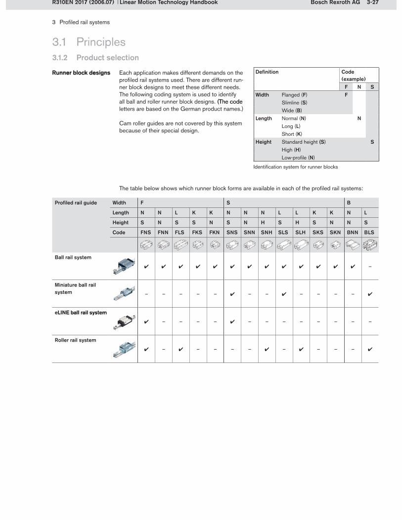
3-27Bosch Rexroth AG
3 Profiled rail systems
Linear Motion Technology HandbookR310EN 2017 (2006.07)
3.1.2 Product selection
3.1 Principles
Each application makes different demands on the profiled rail systems used. There are different run-ner block designs to meet these different needs. The following coding system is used to identify all ball and roller runner block designs. (The code(The code letters are based on the German product names.)
Cam roller guides are not covered by this system because of their special design.
Runner block designsRunner block designs
The table below shows which runner block forms are available in each of the profiled rail systems:
Profiled rail guide Width F S B
Length N N L K K N N N L L K K N L
Height S N S S N S N H S H S N N S
Code FNS FNN FLS FKS FKN SNS SNN SNH SLS SLH SKS SKN BNN BLS
Ball rail system
–
Miniature ball rail system – – – – – – – – – – –
eLINE ball rail systemLINE ball rail system
– – – – – – – – – – – –
Roller rail system
– – – – – – – – –
Definition Code (example)
F N SWidth Flanged (F) F
Slimline (S)Wide (B)
Length Normal (N) NLong (L)Short (K)
Height Standard height ( (S) SHigh (H)Low-profile (N)
Identification system for runner blocks

3-28 Bosch Rexroth AG
3 Profiled rail systems
Linear Motion Technology Handbook R310EN 2017 (2006.07)
3.1 Principles3.1.2 Product selection
The demands made on profiled rail systems vary according to the specific application.System characteristicsSystem characteristics
Profiled rail guide Load capacity Rigidity Accuracy Friction Maximumspeed
Ball rail system
+++ ++ +++ +++ 10 m/s
Miniature ball rail system ++ ++ ++ +++ 5 m/s
eLINE ball rail system
++ + ++ +++ 2 m/s
Roller rail system
+++ +++ +++ ++ 3 m/s
Cam roller guide
+ o + +++ 10 m/s
+++ Very good++ Good+ Satisfactoryo Adequate
Profiled rail guide Short stroke characteristics
Noise characteristics Lubrication requirement
Costs
Ball rail system
++ +++ ++ ++
Miniature ball rail system ++ ++ +++ ++
eLINE ball rail system
++ ++ +++ +++
Roller rail system
+++ ++ ++ +
Cam roller guide
++ +++ +++ ++
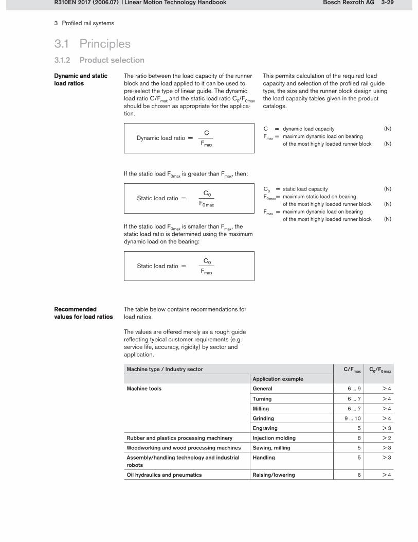
3-29Bosch Rexroth AG
3 Profiled rail systems
Linear Motion Technology HandbookR310EN 2017 (2006.07)
3.1.2 Product selection
3.1 Principles
The ratio between the load capacity of the runner block and the load applied to it can be used to pre-select the type of linear guide. The dynamic load ratio C/Fmax and the static load ratio C0/F0max should be chosen as appropriate for the applica-tion.
This permits calculation of the required load capacity and selection of the profiled rail guide type, the size and the runner block design using the load capacity tables given in the product catalogs.
Dynamic and static load ratiosDynamic and static load ratios
The table below contains recommendations for load ratios.
The values are offered merely as a rough guide reflecting typical customer requirements (e.g. service life, accuracy, rigidity) by sector and application.
Recommended values for load ratiosRecommended values for load ratios
C = dynamic load capacity (N)Fmax = maximum dynamic load on bearing
of the most highly loaded runner block (N)
C0 = static load capacity (N)F0 max = maximum static load on bearing
of the most highly loaded runner block (N)Fmax = maximum dynamic load on bearing
of the most highly loaded runner block (N)
Machine type / Industry sector C/Fmax C0/F0 max
Application example
Machine tools General 6 ... 9 > 4
Turning 6 ... 7 > 4
Milling 6 ... 7 > 4
Grinding 9 ... 10 > 4
Engraving 5 > 3
Rubber and plastics processing machinery Injection molding 8 > 2
Woodworking and wood processing machines Sawing, milling 5 > 3
Assembly/handling technology and industrial robots
Handling 5 > 3
Oil hydraulics and pneumatics Raising/lowering 6 > 4
If the static load F0max is greater than Fmax, then:
If the static load F0max is smaller than Fmax, the static load ratio is determined using the maximum dynamic load on the bearing:
Dynamic load ratio = ==
Static load ratio =
Static load ratio =

3-30 Bosch Rexroth AG
3 Profiled rail systems
Linear Motion Technology Handbook R310EN 2017 (2006.07)
3.1.2 Product selection
3.1 Principles
Many different parameters must be considered to arrive at the optimal choice of profiled rail guide. Though the selection procedure described below is a typical one, it may not apply to all applica-tions. For some applications it may be useful to switch the order of the steps involved. Often, the starting situations will be different. While new-build projects generally give designers full freedom of choice, the range of available options will be restricted at the outset when modifying
3.1.2.2 Product selection procedure
existing designs. Also, some types of guide are more commonly used in certain sectors and applications than in others. Another point to be considered at an early stage is the level of accuracy required, as this may eliminate some versions in the first place. It is therefore advisable to run through all the steps once to gain a better idea of the possible options before proceeding to select the product and perform the nominal life calculations.
When selecting profiled rail systems, the first step is to define the requirements and operating condi-tions for the application, as shown at right.
Step 1: Define the requirements
Step 1: Define the requirements
Procedure
Step 1 Define the requirements
Step 2 Select an appropriate profiled rail guide
Step 3 Define the layout for the profiled rail guide
Step 4 Define the preload class
Step 5 Perform the calculations
Step 6 Define the accuracy class
Step 7 Define the peripherals
Result Ordering details with part numbers
Requirements
Stroke length
Speed
Acceleration
Masses
Loads
Accuracy
Rigidity
Installation space
Travel cycles
Required life
Environmental conditions
Operating conditions
Additional functions (position measurement, drive, brakes)

3-31Bosch Rexroth AG
3 Profiled rail systems
Linear Motion Technology HandbookR310EN 2017 (2006.07)
3.1.2 Product selection
3.1 Principles
The next step is to roughly calculate or estimate the expected loads for the individual runner blocks. The appropriate profiled rail system (type, size and runner block design) can then be selected using the load capacities and the selection charts. The load capacities can be found in the respective Rexroth product catalogs. The static and dynamic load ratios (C0/F0max and C/Fmax) must also be taken into account here. The selec-tion tables were introduced in section 3.1.2.1. They refer to the sizes, runner block designs, and system characteristics.
Step 2: Select an appropriate profiled rail guide
Step 2: Select an appropriate profiled rail guide
Profiled rail guides Abbreviation Section
Ball rail system BRS 3.2
Miniature ball rail system Mini BRS 3.3
eLINE ball rail system eLINE BRS 3.4
Roller rail system RRS 3.5
Cam roller guide CRG 3.6
The layout for the profiled rail system now has to be defined (see section 3.1.3). Define the number of runner blocks and guide rails first. Then define the mounting orientation (horizontal, vertical, inclined, wall mounting or overhead mounting). Finally, determine how the guide rails and runner blocks are to be mounted and fastened, keeping the location and use of the reference edges in mind.
Step 3: Define the layout for the profiled rail guide
Step 3: Define the layout for the profiled rail guide
Layout parameters Section
Number of runner blocks and guide rails
3.1.3.1
Mounting orientation 3.1.3.2
Guide rail mounting 3.1.3.3
Runner block mounting 3.1.3.4
Design of the adjoining structure 3.1.3.5
The preload class is chosen on the basis of the required rigidity. The rigidity charts should be con-sulted to check whether the desired rigidity will be achieved. If this check shows that the rigidity will not be high enough, the linear guide must be redimensioned. The tables listing the preload classes according to areas of use and applica-tions can be used as a rough guide here.
Step 4: Define the preload class
Step 4: Define the preload class
Section
Selection of the preload class 3.1.1.3

3-32 Bosch Rexroth AG
3 Profiled rail systems
Linear Motion Technology Handbook R310EN 2017 (2006.07)
3.1.2 Product selection
3.1 Principles
Using the available data, calculate the nominal life and the static load safety factor. If the required values are not met, repeat steps one to four and select a more appropriate profiled rail guide. Rexroth provides a special design calculation service to assist with nominal life calculations.
Step 5:CalculationsStep 5:Calculations
Procedure for calculations Section
Define the operating conditions 3.1.5.2
Forces and load moments 3.1.5.3
Combined equivalent load on bearing 3.1.5.4
Taking preload into account 3.1.5.5
Equivalent dynamic load on bearing 3.1.5.6
Nominal life 3.1.5.7
Equivalent static load on bearing 3.1.5.8
Static load safety factor 3.1.5.9
Once the nominal life requirements are fulfilled, the next step is to define the accuracy class. This depends heavily on the area and application in which the linear guide is to be used. Help is pro-vided in the form of selection charts and tables.
Step 6:Define the accuracy class
Step 6:Define the accuracy class
Section
Selection of the accuracy class 3.1.1.5
The last step is to define the peripherals for the linear guide. This includes specifying the lubrica-tion system and the in-service lubrication inter-vals. Adequate protection against life-shortening factors must be also be selected, i.e. appropriate sealing and corrosion protection.
Rexroth linear guides can be equipped with ad-ditional functionalities such as clamping and brak-ing units, rack and pinion drives, and integrated measuring systems.
Step 7: Define the peripherals
Step 7: Define the peripherals
Defining the peripherals Section
Lubrication 3.1.6.1
Sealing 3.1.6.2
Corrosion protection
3.1.6.3
Additional functions
Clamping and braking units
3.1.6.4
Rack and pinion drive 3.1.6.4
Integrated measuring system
3.7
After this final step, all the required ordering de-tails are known, including the part numbers for the runner blocks, guide rails and the required accessories.
Result:Ordering details with part numbers
Result:Ordering details with part numbers
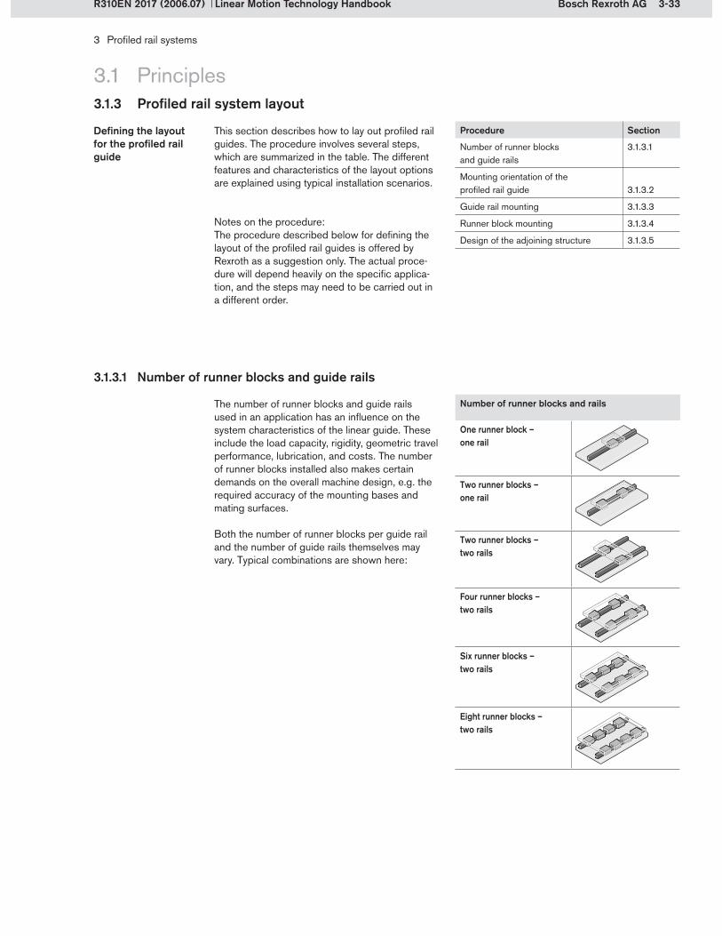
3-33Bosch Rexroth AG
3 Profiled rail systems
Linear Motion Technology HandbookR310EN 2017 (2006.07)
3.1.3 Profiled rail system layout
3.1 Principles
3.1.3.1 Number of runner blocks and guide rails
The number of runner blocks and guide rails used in an application has an influence on the system characteristics of the linear guide. These include the load capacity, rigidity, geometric travel performance, lubrication, and costs. The number of runner blocks installed also makes certain demands on the overall machine design, e.g. the required accuracy of the mounting bases and mating surfaces.
Both the number of runner blocks per guide rail and the number of guide rails themselves may vary. Typical combinations are shown here:
Number of runner blocks and rails
One runner block –one rail
Two runner blocks –one rail
Two runner blocks –two rails
Four runner blocks –two rails
Six runner blocks –two rails
Eight runner blocks –two rails
This section describes how to lay out profiled rail guides. The procedure involves several steps, which are summarized in the table. The different features and characteristics of the layout options are explained using typical installation scenarios.
Procedure Section
Number of runner blocks and guide rails
3.1.3.1
Mounting orientation of the profiled rail guide
3.1.3.2
Guide rail mounting 3.1.3.3
Runner block mounting 3.1.3.4
Design of the adjoining structure 3.1.3.5
Notes on the procedure:The procedure described below for defining the layout of the profiled rail guides is offered by Rexroth as a suggestion only. The actual proce-dure will depend heavily on the specific applica-tion, and the steps may need to be carried out in a different order.
Defining the layout for the profiled rail guide
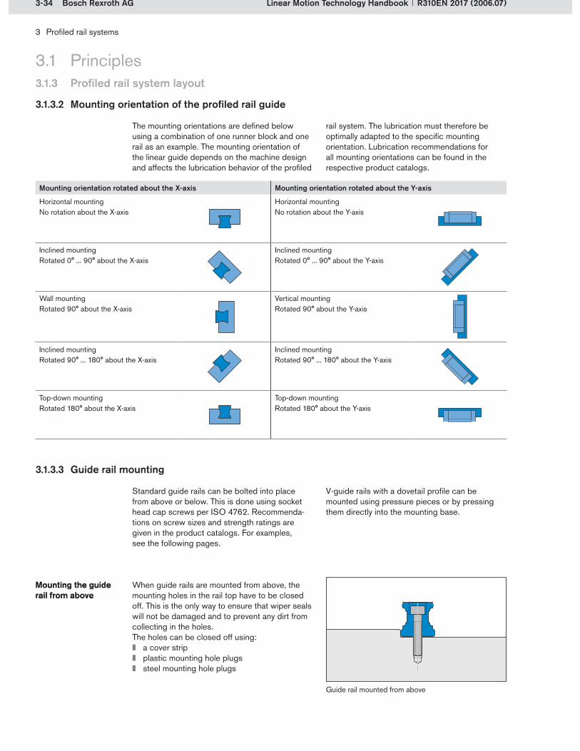
3-34 Bosch Rexroth AG
3 Profiled rail systems
Linear Motion Technology Handbook R310EN 2017 (2006.07)
3.1.3 Profiled rail system layout
3.1 Principles
3.1.3.2 Mounting orientation of the profiled rail guide
The mounting orientations are defined below using a combination of one runner block and one rail as an example. The mounting orientation of the linear guide depends on the machine design and affects the lubrication behavior of the profiled
rail system. The lubrication must therefore be optimally adapted to the specific mounting orientation. Lubrication recommendations for all mounting orientations can be found in the respective product catalogs.
Mounting orientation rotated about the X-axis Mounting orientation rotated about the Y-axis
Horizontal mountingNo rotation about the X-axis
Horizontal mountingNo rotation about the Y-axis
Inclined mountingRotated 0° ... 90° about the X-axis
Inclined mountingRotated 0° ... 90° about the Y-axis
Wall mountingRotated 90° about the X-axis
Vertical mountingRotated 90° about the Y-axis
Inclined mountingRotated 90° ... 180° about the X-axis
Inclined mountingRotated 90° ... 180° about the Y-axis
Top-down mountingRotated 180° about the X-axis
Top-down mountingRotated 180° about the Y-axis
3.1.3.3 Guide rail mounting
Standard guide rails can be bolted into place from above or below. This is done using socket head cap screws per ISO 4762. Recommenda-tions on screw sizes and strength ratings are given in the product catalogs. For examples, see the following pages.
V-guide rails with a dovetail profile can be mounted using pressure pieces or by pressing them directly into the mounting base.
When guide rails are mounted from above, the mounting holes in the rail top have to be closed off. This is the only way to ensure that wiper seals will not be damaged and to prevent any dirt from collecting in the holes.The holes can be closed off using:
a cover stripplastic mounting hole plugssteel mounting hole plugs
Mounting the guide rail from aboveMounting the guide rail from above
Guide rail mounted from above
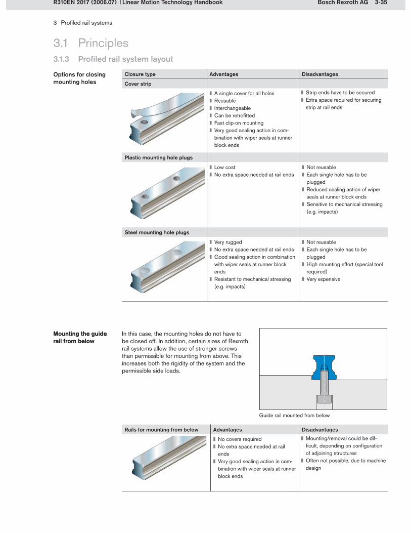
3-35Bosch Rexroth AG
3 Profiled rail systems
Linear Motion Technology HandbookR310EN 2017 (2006.07)
3.1.3 Profiled rail system layout
3.1 Principles
Closure type Advantages Disadvantages
Cover strip
A single cover for all holesReusableInterchangeableCan be retrofittedFast clip-on mountingVery good sealing action in com-bination with wiper seals at runner block ends
Strip ends have to be securedExtra space required for securing strip at rail ends
Plastic mounting hole plugs
Low costNo extra space needed at rail ends
Not reusableEach single hole has to be pluggedReduced sealing action of wiper seals at runner block endsSensitive to mechanical stressing (e.g. impacts)
Steel mounting hole plugs
Very ruggedNo extra space needed at rail endsGood sealing action in combination with wiper seals at runner block endsResistant to mechanical stressing (e.g. impacts)
Not reusableEach single hole has to be pluggedHigh mounting effort (special tool required) Very expensive
In this case, the mounting holes do not have to be closed off. In addition, certain sizes of Rexroth rail systems allow the use of stronger screws than permissible for mounting from above. This increases both the rigidity of the system and the permissible side loads.
Mounting the guide rail from belowMounting the guide rail from below
Rails for mounting from below Advantages Disadvantages
No covers requiredNo extra space needed at rail endsVery good sealing action in com-bination with wiper seals at runner block ends
Mounting/removal could be dif-ficult, depending on configuration of adjoining structures Often not possible, due to machine design
Guide rail mounted from below
Options for closing mounting holes

3-36 Bosch Rexroth AG
3 Profiled rail systems
Linear Motion Technology Handbook R310EN 2017 (2006.07)
3.1.3 Profiled rail system layout
3.1 Principles
V-guide rail with pressure piece
V-guide railwith pressure pieces
Advantages Disadvantages
No rail cover/plugs requiredNo screws directly in the rail, therefore no wavinessNo additional lateral retention requiredNo extra space needed at rail ends
Extra space needed at sideHigh effort required to prepare the machine bed and mount the rails
Rexroth offers guide rails with a dovetail profile (V-guide rails) for the most commonly used sizes. The rail itself contains no mounting holes. It is mounted by inserting it into a suitably fabricated machine bed and wedged into place from the side using screw-down pressure pieces. V-guide rails with pressure pieces are available for roller rail systems.
Mounting of V-guide rail using pressure pieces
Mounting of V-guide rail using pressure pieces
V-guide rails can also be mounted by pressing (levering) them into the mounting base. The rail is held firmly in place due to plastic deformation of the mounting base. The mounting base must be made from a suitable material, e.g. aluminum. Press-fitting reduces the costs for manufacturing the adjoining structure and for mounting the guide rail. V-guide rails for press-fitting are available for ball rail systems.
Press-fitting the V-guide rail into mounting base
Press-fitting the V-guide rail into mounting base
V-guide rail mounted by press-fitting
V-guide rail for press-fitting Advantages Disadvantages
No cover/plugs requiredNo screw-fastenersFast mountingReduced costsNo need to bore holes or tap threads in the adjoining structure
Extra space needed at sideRequires special mounting toolsReduced load-bearing capability due to aluminum mounting base

3-37Bosch Rexroth AG
3 Profiled rail systems
Linear Motion Technology HandbookR310EN 2017 (2006.07)
3.1.3 Profiled rail system layout
3.1 Principles
The choice of rail mounting option will depend on the specific application. The following table shows nine different mounting options and the mounting time required in each case. The infor-
Comparison of mounting options and mounting times
Comparison of mounting options and mounting times
Option Illustration Description Mounting time in %
1 Guide rail mounted from above. The mounting holes are not plugged. This option is not recommended by Rexroth. It is shown here merely for the purpose of comparison.
100
2 Guide rail mounted from above and with cover strip. The strip is secured by a clamp at each end. 125
3 Guide rail mounted from above and with cover strip. The strip is secured by screw-down protective caps. 130
4 Guide rail mounted from above. The mounting holes are then closed with plastic plugs. 125
5 Guide rail mounted from above. The mounting holes are then closed with steel plugs, which are pressed in using a special tool.
225
6 Guide rail mounted from above. Additional lateral retention is provided in the form of a wedge profile. This option with open mounting holes is shown merely for the purpose of comparison.
180
7 Guide rail mounted from below.
130
8 V-guide rail mounted using pressure pieces. Since the pressure pieces already provide lateral retention, this option can be com-pared with option 6. The mounting time is considerably shorter.
130
9 V-guide rail pressed into aluminum mounting base.
115
mation relates to a size 25 ball guide rail with a rail length of 536 mm, mounted using 9 screws.

3-38 Bosch Rexroth AG
3 Profiled rail systems
Linear Motion Technology Handbook R310EN 2017 (2006.07)
3.1 Principles3.1.3 Profiled rail system layout
The high performance capability of profiled rail systems may cause the load limits for screw connections as specified in DIN 645-1 to be exceeded. The most critical point is the screw connection between the guide rail and the mount-ing base. If the lift-off loads Fz or moments Mx are higher than the maximum permissible loads Fz max
Load on the screw connections of guide rails
Load on the screw connections of guide rails
Loads on the screw connections for a guide rail mounted from above
The values shown in the table apply under the following conditions:
Mounting screw quality 12.9Screws tightened to the specified torqueScrews lightly oiledRails screwed down to steel or cast iron basesScrew-in depth at least 2x thread diameterFor screws in quality 8.8, an approximation factor of 0.6 can be applied.
If any side loads act on the linear guide, the screw connections must additionally be checked for lateral strength (see section 3.1.3.5).
Guide rail Size Static lift-off loads Fz and moment loads MxShort runner block Normal runner block Long runner block
FKS, SKS, FKN, SKN FNS, SNS, SNH, FNN, SNN
FLS, SLS, SLH
Fz max Mx max Fz max Mx max Fz max Mx maxN Nm N Nm N Nm
Mounted from above
20 10 000 90 11 700 106 13 400 12125 14 600 154 17 100 180 19 500 20530 – 360 32 400 420 37 100 480
Mounted from below
20 – 128 16 500 149 18 900 17025 14 300 150 16 700 170 19 100 20030 – 350 31 700 410 36 200 470
and moments Mx max shown in the table, the screw connections must be recalculated.
Details of the permissible loads are given in the respective product catalogs. The table shows an extract from the ball rail systems catalog.
Loads on the screw connections for a guide rail mounted from below
The table shows examples of the maximum permissible values for lift-off loads and moments acting on runner blocks in relation to the screw-connections of the guide rails:
Sample values from the ball rail systems product catalog

3-39Bosch Rexroth AG
002 002001 001
c)
b)a)
d)
b)a)
d)c)
001 001
c) c)d)
a)
3 Profiled rail systems
Linear Motion Technology HandbookR310EN 2017 (2006.07)
One-piece guide rails can only be supplied up to a certain maximum length. This maximum length depends on the type, size and configuration of the profiled rail system. If longer rail lengths are required, these can be supplied as composite
Composite guide railsComposite guide rails
rails made up of matching rail sections mounted end to end. The end faces of the rail sections are machined to ensure a seamless transition at the joints with full load-bearing capability.
3.1 Principles3.1.3 Profiled rail system layout
In composite rails the full identification code is marked on both the first and the last rail section. The joints (a) are marked with a number (d) identi-fying the specific joint. They are also marked with
Identification of composite guide rails
Identification of composite guide rails
a serial rail number (b) to ensure that the sections can be mounted in the right order.
Guide rail made up of two sections
Guide rail made up of three or more sections
a) Jointb) Serial rail numberc) Full rail identification on first and last sectionsd) Joint number

3-40 Bosch Rexroth AG
3 Profiled rail systems
Linear Motion Technology Handbook R310EN 2017 (2006.07)
3.1.3 Profiled rail system layout
3.1 Principles
3.1.3.4 Runner block mounting
Just as with the guide rails, the runner block range also offers the possibility of fastening at-tachments from above or below. However, care should be taken to select the correct runner block
All runner blocks have standardized threaded mounting holes for top-down fastening of attach-ments. The threads are metric sizes 4, 6 or 9. The number of holes and the mounting hole pattern depend on the type, size and version of runner block.
Top-down fastening of attachments to runner block
Top-down fastening of attachments to runner block
Example of top-down fastening
Example of bottom-up fastening
version (see below) for the chosen mounting method. If required, the runner blocks can be additionally secured by pinning.
The flanged runner block versions also allow bottom-up fastening of attachments. The mount-ing hole pattern for this option is standardized. The middle mounting holes will only accommo-date socket head cap screws with a low-profile head as specified in DIN 6912.
Bottom-up fastening of attachments to runner blocks
Bottom-up fastening of attachments to runner blocks
Pinning for added security
Runner blocks can also be pinned to increase their lateral rigidity. The positions for pin holes are indicated in the respective catalogs. Pre-drilled holes made for production purposes may already exist at these positions. These holes can be bored open. Hardened tapered or straight pins per ISO 8734 can be used for runner block pinning.
Pinning of runner blocksPinning of runner blocks

3-41Bosch Rexroth AG
O 2 O 1
O6
O 1 O 4
O3
O 4 O 4
3 Profiled rail systems
Linear Motion Technology HandbookR310EN 2017 (2006.07)
3.1.3 Profiled rail system layout
3.1 Principles
3.1.3.5 Design of the adjoining structure
Examples of screw-fasteners used to mount runner blocks and guide rails
When side loads are to be expected, it is essen-tial to check whether the chosen screw-fasteners will be capable of transmitting these forces. This check can be done using the tables provided in the product catalogs. The tables contain size-related values for permissible side loads without lateral retention. These values are listed
Permissible side loads without lateral retention
Permissible side loads without lateral retention
with reference to the dynamic load capacity C. If the maximum permissible value is exceeded, reinforcement must be provided in the form of a reference edge, lateral retention or pinning.
The table below shows sample data from the ball rail systems catalog.
Example:A size 25 FNS runner block is to be mounted by top-down fastening using six socket head cap screws (O4, M8 x 20, strength class 12.9, per
ISO 4762). The guide rail is also to be mounted by top-down fastening with socket head cap screws (O3, M6 x 30, strength class 12.9, per ISO 4762).
Result:The runner block can be subjected to a maximum side load of 0.35 C (35% C). The screws used to fasten the guide rail can only transmit up to 0.10 C (10% C) without a reference edge or lateral retention.
Any higher load will require a reference edge, lateral retention or pinning.
Size Screw sizesRunner block Guide rail
O1ISO 4762
4 pcs.
O2DIN 6912
2 pcs.
O4ISO 4762
6 pcs.
O3ISO 4762
O6ISO 4762
20 M5x16 M5x12 M6x16 M5x25 M6x1625 M6x20 M6x16 M8x20 M6x30 M6x2030 M8x25 M8x16 M10x20 M8x30 M8x20
Screw strength class
Permissible side load without lateral retentionRunner block Guide rail
O1 O2 O4 O3 O68.8 11% C 15% C 23% C 6% C 6% C12.9 18% C 22% C 35% C 10% C 10% C
Sample values from the ball rail systems product catalog
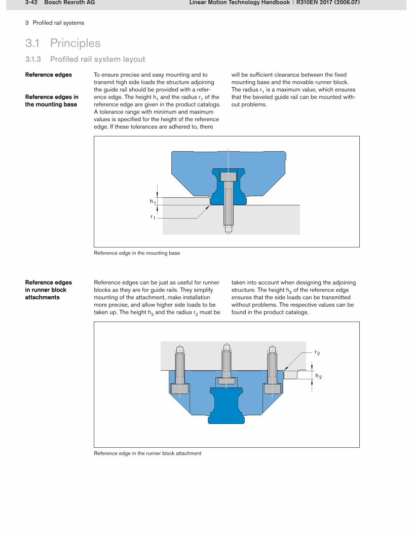
3-42 Bosch Rexroth AG
3 Profiled rail systems
Linear Motion Technology Handbook R310EN 2017 (2006.07)
3.1 Principles3.1.3 Profiled rail system layout
To ensure precise and easy mounting and to transmit high side loads the structure adjoining the guide rail should be provided with a refer-ence edge. The height h1 and the radius r1 of the reference edge are given in the product catalogs. A tolerance range with minimum and maximum values is specified for the height of the reference edge. If these tolerances are adhered to, there
Reference edgesReference edges
Reference edges in the mounting baseReference edges in the mounting base
Reference edge in the mounting base
Reference edge in the runner block attachment
Reference edges can be just as useful for runner blocks as they are for guide rails. They simplify mounting of the attachment, make installation more precise, and allow higher side loads to be taken up. The height h2 and the radius r2 must be
Reference edges in runner block attachments
Reference edges in runner block attachments
will be sufficient clearance between the fixed mounting base and the movable runner block. The radius r1 is a maximum value, which ensures that the beveled guide rail can be mounted with-out problems.
taken into account when designing the adjoining structure. The height h2 of the reference edge ensures that the side loads can be transmitted without problems. The respective values can be found in the product catalogs.
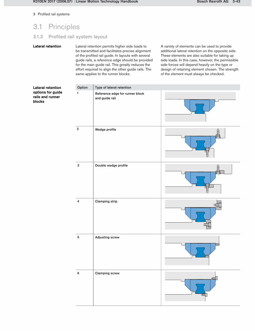
3-43Bosch Rexroth AG
3 Profiled rail systems
Linear Motion Technology HandbookR310EN 2017 (2006.07)
3.1.3 Profiled rail system layout
3.1 Principles
Lateral retention permits higher side loads to be transmitted and facilitates precise alignment of the profiled rail guide. In layouts with several guide rails, a reference edge should be provided for the main guide rail. This greatly reduces the effort required to align the other guide rails. The same applies to the runner blocks.
Lateral retention options for guide rails and runner blocks
Lateral retention options for guide rails and runner blocks
Lateral retentionLateral retention A variety of elements can be used to provide additional lateral retention on the opposite side. These elements are also suitable for taking up side loads. In this case, however, the permissible side forces will depend heavily on the type or design of retaining element chosen. The strength of the element must always be checked.
Option Type of lateral retention
1 Reference edge for runner block and guide rail
2 Wedge profile
3 Double wedge profile
4 Clamping strip
5 Adjusting screw
6 Clamping screw

3-44 Bosch Rexroth AG
3 Profiled rail systems
Linear Motion Technology Handbook R310EN 2017 (2006.07)
3.1 Principles3.1.3 Profiled rail system layout
Option Type of lateral retention
7 Shaft with countersunk screw
8 Clamping piece with countersunk screw
9 Clamping piece with tapered countersink
10 Press-fitted rail
11 V-guide rail with pressure piece
12 Press-fitted V-guide rail
When specifying the layout and number of refer-ence edges and/or lateral retention elements for guide rails and runner blocks, the following four factors must be taken into account:
LoadAccuracyMounting methodGeometry
Layout of reference edges and lateral retention elements
Layout of reference edges and lateral retention elements
An additional factor is the cost, which should always be checked when selecting the lateral retention option. This includes checking the cost of purchase and manufacturing as well as the expected installation costs.

3-45Bosch Rexroth AG
3 Profiled rail systems
Linear Motion Technology HandbookR310EN 2017 (2006.07)
3.1.3 Profiled rail system layout
3.1 Principles
The magnitude and direction of the loads acting on the linear guide unit determine the number and arrangement of the lateral reference edges. If the permissible values for side loads (see 3.1.3.5) are exceeded, reference edges or additional lateral retention must be provided. Reference edges and lateral retention also increase the rigidity of the system. These reinforcements are therefore recommended for applications involving impacts and vibration.
LoadsLoads For the transmission of side loads the reference edges should be arranged according to the force flow in the system. Purely vertical loads (lift-off and down loads) have no effect on the layout of the reference edges. The exception here is the V-guide rail, where lateral retention is an integral feature of the mounting method. The examples below illustrate the various load scenarios:
Loads Reference edges Features
Without reference edgesMounting of runner block and guide rail without reference edges
Suitable for transmitting low side loads which can be transmitted via the screw connections.
2 reference edgesMounting of runner block and guide rail with one reference edge each (on opposite sides)
Suitable for transmitting high side loads in one direction.
4 reference edgesMounting of runner block and guide rail with two reference edges each (additional lateral retention in each case)
Suitable for transmitting alternating side loads. The higher load should be trans-mitted through the reference edges.
Though the loads themselves might not always require a reference edge, it is often necessary to mount the guide rail with a reference edge,
AccuracyAccuracy in order to achieve the required accuracy of the overall installation.
Illustration Accuracy Features
Without reference edgeLow to high accuracy (depending on mounting method)
The accuracy is determined by the straightness of the rail. Higher levels of accuracy can be achieved by aligning the rail during installation.
1 reference edgeHigh accuracy
The accuracy is determined by the precision with which the rail is pushed against the reference edge during installation and by the straightness of the reference edge.
2 reference edgesVery high accuracy
The accuracy is determined by the precision of mounting and by the straightness of the reference edge and the lateral retention.
Note: The straightness deviations of the guide rail have been deliberately exaggerated in the illustrations.
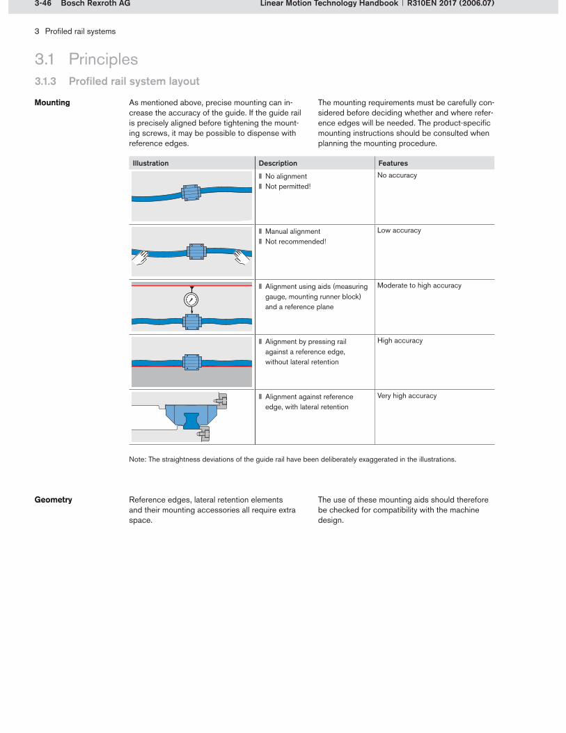
3-46 Bosch Rexroth AG
3 Profiled rail systems
Linear Motion Technology Handbook R310EN 2017 (2006.07)
3.1 Principles3.1.3 Profiled rail system layout
As mentioned above, precise mounting can in-crease the accuracy of the guide. If the guide rail is precisely aligned before tightening the mount-ing screws, it may be possible to dispense with reference edges.
MountingMounting The mounting requirements must be carefully con-sidered before deciding whether and where refer-ence edges will be needed. The product-specific mounting instructions should be consulted when planning the mounting procedure.
Illustration Description Features
No alignmentNot permitted!
No accuracy
Manual alignmentNot recommended!
Low accuracy
Alignment using aids (measuring gauge, mounting runner block) and a reference plane
Moderate to high accuracy
Alignment by pressing rail against a reference edge, without lateral retention
High accuracy
Alignment against reference edge, with lateral retention
Very high accuracy
Reference edges, lateral retention elements and their mounting accessories all require extra space.
GeometryGeometry The use of these mounting aids should therefore be checked for compatibility with the machine design.
Note: The straightness deviations of the guide rail have been deliberately exaggerated in the illustrations.

3-47Bosch Rexroth AG
3 Profiled rail systems
Linear Motion Technology HandbookR310EN 2017 (2006.07)
3.1.3 Profiled rail system layout
3.1 Principles
3.1.3.6 Installation scenarios
The following illustrations show typical installation scenarios. These scenarios reflect the layouts, mounting orientations, mounting methods and de-sign criteria described earlier. Most of them relate to applications with 2 rails and 4 runner blocks,
as this is the most commonly used combination. Provided as design aids, these examples give an insight into the great variety of configurations that can be found in practice.
Installation scenario
Description
1 No reference edgesFor high lift-off and down loadsLow side loads possibleHigh mounting effort
2 Runner block and guide rail with one reference edge each (on opposite sides)Higher side loads from one direction permittedEasy mounting due to reference edgesHigh accuracy
3 Both guide rails with one reference edgeRunner blocks without reference edges
4 Both guide rails with one reference edgeOne runner block with reference edgeEasy mountingHigh accuracySuitable for high side loads from one direction
5 Runner block and guide rail on one side with reference edge and lateral retentionRunner block with reference edge takes up all side loadsFor high side loads from both directionsEasy mounting
6 First guide rail with reference edge, second with reference edge and lateral retentionRunner block with reference edge and lateral retention takes up side loadsHigh accuracy

3-48 Bosch Rexroth AG
3 Profiled rail systems
Linear Motion Technology Handbook R310EN 2017 (2006.07)
Installation scenario
Description
7 One runner block and two guide rails braced via reference edges and lateral retentionHigh side loads possibleVery high accuracy
8 Runner blocks and guide rails braced via reference edges and lateral retentionPinning in addition to screw-fasteners for very high side loadsVery high accuracy
9 Inclined installation, rotated 45° about X-axisFor very high loads acting at an angle of 45°
10 Vertical installation, rotated 90° about X-axis (wall mounting)Both guide rails with reference edge For high horizontal loadsHigh accuracy
11 Top-down installation, rotated 180° about X-axisFor mainly vertical loadsHigher side loads from one direction possible
12 For loads acting mainly from above and from the sideLow space requirementHigh mounting effortIntermediate adapter plate required
13 For mainly horizontal loadsLow space requirementHigh mounting effortIntermediate adapter plate required
14 “L” layout to take up moment loadsHigh moment load capacity
3.1 Principles3.1.3 Profiled rail system layout

3-49Bosch Rexroth AG
3 Profiled rail systems
Linear Motion Technology HandbookR310EN 2017 (2006.07)
Installation scenario
Description
15 Four guide rails to carry extremely heavy loadsVery high rigidity
16 Short travel distances within a relatively large machineFour short rails
17 Very high rigidity with load acting centrallyVery high mounting effortIntermediate adapter plates required
18 Guide rail travelsRunner blocks stationary
3.1.3 Profiled rail system layout
3.1 Principles

3-50 Bosch Rexroth AG
3 Profiled rail systems
Linear Motion Technology Handbook R310EN 2017 (2006.07)
3.1.4 Design notes
3.1 Principles
This section provides information for design engineers on how to plan and install profiled rail systems. The following topics are dealt with in detail:
Installation tolerancesGuidelines for economical designs
A number of tolerances must be met to ensure that a profiled rail system will deliver full perfor-mance. Deviations from the specified values can shorten the life of the guide. As long as the deviations are kept within the tolerance limits, the effect on the service life can generally be neglected.
The installation tolerances relate to:Vertical offsetParallelism offset of mounted railsTolerances for different installation situationsSurface finish details
Permissible tolerances are specified for vertical offsets in the longitudinal and transverse direc-tions. These tolerances vary according to the design of the runner block. “Super” runner blocks, which have a self-alignment capability, and runner blocks made from aluminum can compensate for larger errors than runner blocks made from steel. The runner block version (e.g. long or short) also determines the tolerance limits. Specific details can be found in the respective product catalogs.
Vertical offsetVertical offset
3.1.4.1 Installation tolerances
Self alignment capability in “Super” runner blocks
Short ball runner block (SKS) Long ball runner block (SLS)

3-51Bosch Rexroth AG
a
S1
3 Profiled rail systems
Linear Motion Technology HandbookR310EN 2017 (2006.07)
3.1 Principles3.1.4 Design notes
Vertical offset in the transverse direction
Runner block Length Calculation factor Y for preload class
C0 C1 C2 C3Steel runner block Standard/long 4.3 · 10 –4 2.8 . 10 –4 1.7 . 10 –4 1.2 . 10 –4
Short 5.2 · 10 –4 3.4 . 10 –4 2.0 . 10 –4 1.4 . 10 –4
“Super” runner block Short 8.0 . 10 –4 6.0 . 10 –4 – –
Aluminum runner block Standard 7.0 . 10 –4 5.0 . 10 –4 – –
(3-8)
S1 = permissible vertical offset (mm)a = distance between guide rails (mm)Y = calculation factor (–)
The permissible vertical offset in the transverse direction is calculated from the distance between guide rails “a” and a calculation factor Y, which depends on the preload class (C0, C1, C2, C3) of the runner blocks.
Permissible vertical offset in the trans-verse direction S1
Permissible vertical offset in the trans-verse direction S1
The calculation factor Y also depends on the run-ner block design (steel, aluminum, “Super” runner block) and on its length. For short runner blocks, the offset can be 20% higher than the permis-sible value for standard-length runner blocks.
S1 = a · Y
Example for a Rexroth ball rail system with 4 rows of balls:

3-52 Bosch Rexroth AG
b
S2
3 Profiled rail systems
Linear Motion Technology Handbook R310EN 2017 (2006.07)
3.1 Principles3.1.4 Design notes
Vertical offset in the longitudinal direction
(3-9)
S2 = permissible vertical offset (mm)b = distance between runner blocks (mm)X = calculation factor (–)
Runner block Calculation factor X for runner block length
Standard Long ShortSteel runner block 4.3 . 10 –5 3.0 . 10 –5 6.0 . 10 –5
Aluminum runner block 6.0 . 10 –5 – –
“Super” runner blocks can compensate for longitudinal offsets of up to 10’ due to their self-alignment capability.
Compensation of offsets in “Super” runner blocks
S2 = b · X
Permissible vertical offset in the longitu-dinal direction S2
The permissible vertical offset in the longitudinal direction is calculated from the distance between runner blocks “b” and a calculation factor X, which depends on the material of the runner blocks (steel/aluminum) and on their length.
The values for long runner blocks are approx. 30% lower and the values for short runner blocks approx. 40% higher than the limits for standard-length runner blocks.
Example for a Rexroth ball rail system with 4 rows of balls:

3-53Bosch Rexroth AG
3 Profiled rail systems
Linear Motion Technology HandbookR310EN 2017 (2006.07)
3.1 Principles3.1.4 Design notes
If the guide rails are not aligned parallel to each other, stresses will arise in the guide system, resulting in additional loads and thus shorten-ing the service life. To make sure that this does not happen, the parallelism offset P1 must be observed. As long as the values specified in the table are met, the effect of parallelism offsets on the service life can generally be neglected. The tolerances depend on the specific installation conditions. In precision installations the adjoin-ing structures are rigid and highly accurate. In
Parallelism offset of mounted railsParallelism offset of mounted rails
standard installations the adjoining structures are compliant, allowing parallelism offset tolerances up to twice those for precision installations. The parallelism offset values apply to all runner blocks in the standard range and depend on the preload and the material of the runner block. For short runner blocks, the offset can be 20% higher than the permissible value for standard-length runner blocks.
Parallelism of guide rails
Effect of the runner block version on the parallelism offset, using a size 25 ball rail system as an example:
Runner block Parallelism offset P1 (mm) for preload class
C0 C1 C2 C3
Steel runner block in precision installations
0.019 0.012 0.007 0.005
Short steel runner block in precision installations
0.023 0.014 0.008 0.006
Steel runner block in standard installations
0.038 0.024 0.014 0.010
Short steel runner block in standard installations
0.046 0.029 0.017 0.012
“Super” runner block 0.032 0.023 – –
Aluminum runner block 0.026 0.017 – –
If so requested by customers, Rexroth can check the mounting base and attachments to determine whether they meet the accuracy requirements. This check covers the entire installation situation,
Tolerances for different installation situations
Tolerances for different installation situations
including specification of all necessary shape and positional tolerances. The calculated nominal life can only be achieved when these tolerances are observed.
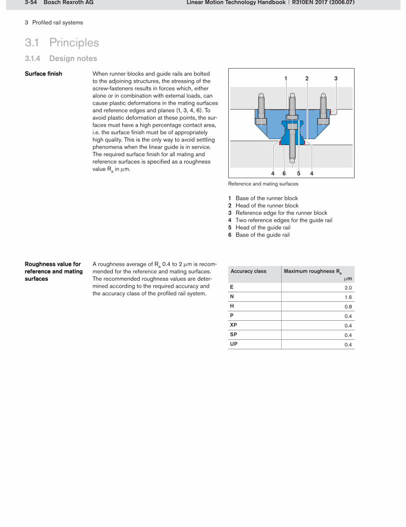
3-54 Bosch Rexroth AG
5
31
4
2
4 6
3 Profiled rail systems
Linear Motion Technology Handbook R310EN 2017 (2006.07)
3.1 Principles3.1.4 Design notes
When runner blocks and guide rails are bolted to the adjoining structures, the stressing of the screw-fasteners results in forces which, either alone or in combination with external loads, can cause plastic deformations in the mating surfaces and reference edges and planes (1, 3, 4, 6). To avoid plastic deformation at these points, the sur-faces must have a high percentage contact area, i.e. the surface finish must be of appropriately high quality. This is the only way to avoid settling phenomena when the linear guide is in service. The required surface finish for all mating and reference surfaces is specified as a roughness value Ra in m.
Surface finishSurface finish
A roughness average of Ra 0.4 to 2 m is recom-mended for the reference and mating surfaces. The recommended roughness values are deter-mined according to the required accuracy and the accuracy class of the profiled rail system.
Roughness value for reference and mating surfaces
Roughness value for reference and mating surfaces
Accuracy class Maximum roughness Ra m
E 2.0
N 1.6
H 0.8
P 0.4
XP 0.4
SP 0.4
UP 0.4
Reference and mating surfaces
Base of the runner blockHead of the runner blockReference edge for the runner blockTwo reference edges for the guide railHead of the guide railBase of the guide rail
1�2�3�4�5�6�

3-55Bosch Rexroth AG
3 Profiled rail systems
Linear Motion Technology HandbookR310EN 2017 (2006.07)
3.1 Principles3.1.4 Design notes
3.1.4.2 Guidelines for economical designs
When using profiled rail systems it is essential to consider and define all requirements in order to determine the required system characteristics. The maxim here is: as accurate as necessary, as inaccurate as possible.
As accurate as nec-essary, as inaccurate as possible
As accurate as nec-essary, as inaccurate as possible
High accuracy classes only make sense if the adjoining structures have the same high accuracy level. Selecting an appropriate accuracy class right from the beginning can considerably reduce costs when it comes to manufacturing the mount-ing base and attachments.
The higher the preload is, the higher the accuracy requirements on the adjoining structures will be. This should be remembered when choosing the preload class. For high preloads, the permissible vertical offset of the mounting base in the trans-verse direction is small.
Preload only as high as necessaryPreload only as high as necessary
The same applies to parallelism tolerances between two guide rails. High accuracy require-ments on the mounting base and the attachments always drive up the manufacturing costs.
The smaller the distance between rails installed parallel to each other, the more accurately the rails have to be aligned vertically.
Ensure a sufficiently large distance between rails
Ensure a sufficiently large distance between rails
The distance between the guide rails should therefore be appropriately sized.
If the attachment has low accuracy, short runner blocks or even self-aligning “Super” runner blocks can be used.
Short or “Super” runner blocks for larger inaccuracies
Short or “Super” runner blocks for larger inaccuracies
Within certain limits, these components can com-pensate for straightness errors in a guide rail.
The adjoining structures should always be designed to allow optimal installation and subsequent maintenance. The space provided for profiled rail systems should therefore be
Ensure sufficient space for linear guides
Ensure sufficient space for linear guides
appropriately dimensioned. The design should also make allowance for easy replacement of the linear guides.
3-56 Bosch Rexroth AG
3 Profiled rail systems
Linear Motion Technology Handbook R310EN 2017 (2006.07)
3.1 Principles3.1.4 Design notes
The use of standard components and preferred lengths reduces the cost of purchase. It also speeds up delivery and reduces spare parts complexity.
Use of standard components and preferred lengths
Use of standard components and preferred lengths
When using linear guides, the same type of profiled rail system should be used per slide or, where possible, per machine or series.
Same linear guides in all axesSame linear guides in all axes
This also reduces the cost of purchase, ware-housing, and installation.
When selecting the lubrication system, it is impor-tant to consider not only the cost of connecting the system up to the runner block, but also the cost of the additional equipment required.
Long-term lubrica-tion for cost-efficient operation
Long-term lubrica-tion for cost-efficient operation
The use of front lube units or the standard long-term lubrication offered by Rexroth profiled rail systems is therefore recommended.
Depending on the application, it may be possible to eliminate a reference edge by pinning the run-ner blocks.
Eliminating a reference edge by pinning runner blocks
Eliminating a reference edge by pinning runner blocks
In linear guides with two or more rails, one rail should be designed as the main rail. This rail should be fixed against a reference edge. All the other rails can then be aligned relative to the main rail during installation.
Design one guide rail as the main railDesign one guide rail as the main rail

3-57Bosch Rexroth AG
3 Profiled rail systems
Linear Motion Technology HandbookR310EN 2017 (2006.07)
3.1.5.1 Procedure for manual calculations
The actual calculation of the nominal life in terms of travel or operating hours requires precise de-termination of the loads acting on the bearings. Finally, the static and dynamic load safety factors have to be checked. The recommended proce-dure is shown below.
3.1 Principles3.1.5 Calculations
Rexroth provides a design calculation service to assist with nominal life calculations. The travel life expectancy is calculated using a software pro-gram called LINEAR MOTION DESIGNER. All the customer has to do is to specify the operating conditions.
Calculation serviceCalculation service
Layout selection page from the LINEAR MOTION DESIGNER calculation software
The nominal life calculation consists of several steps. The calculation principles for determining the nominal life of profiled rail systems will be described first.
Summary of the procedure:Define the operating conditions.Calculate the loads due to forces and moments.Calculate the combined equivalent load on the bearing.Take the preload into account.Calculate the equivalent dynamic load on the bearing.Calculate the life expectancy.Calculate the equivalent static load on the bearing.Calculate the static load safety factor.
Besides using the LINEAR MOTION DESIGNER program, the nominal life can, of course, be cal-culated by conventional methods. The manual procedure is described in detail below.

3-58 Bosch Rexroth AG
3 Profiled rail systems
Linear Motion Technology Handbook R310EN 2017 (2006.07)
3.1 Principles3.1.5 Calculations
Detailed procedure, using a linear guide with two rails and four runner blocks as an example:
Calculation step
Define the operating conditionsData on the guide system, layout,
dynamic cycle and loads
Calculate the loads due to forces and momentsin every phase n for each runner block i
in the y- and z-directions
Calculate the combined equivalent load on the bearingin every phase n and for each runner block i
Take the preload into accountusing the effective equivalent load on the bearing
in every phase n for each runner block i
Calculate the equivalent dynamic load on the bearing
for varying loads for each runner block i
Calculate the nominal or modified life expectancy
at constant or varying speed for each runner block i
Calculate the equivalent static load on the bearing for combined loads for each runner block i
Calculate the static load safety factor
InputData
OutputResult
Machine design (structure, application)
LW, LS, Ly, Lz, , ,m, xS, yS, zS, Fg, FaFp, xp, yp, zp, Fw, j, Fwx, j, Fwy, j, Fwz, j, xw, j, yw, j, zw, j, n, tn, sn, vn, an, qsn, qtn, C, C0 , Xpr, Mt, Mt0, ML, ML0
LW, LS, Ly, LzFwx, j, Fwy, j, Fwz, j(Fg, Fp, Fa)xw, j, yw, j, zw, j(xS, yS, zS, xp, yp, zp)
Fy n i, Fz n i
Fy n i, Fz n i Fcomb n i
C, Xpr, Fcomb n i Fpr, Flim, Feff n i
qsn, Feff n i Fm i
C, Fm i, sstroke, nstroke, qtn, vn, a1
vmLi, Lh i, Lna i
F0 y i, F0 z iM0 x i, M0 y i, M0 z iC0, Mt0, ML0
F0 comb i
C0F0 comb i, Fmax eff n i
S0
Step 1:
Step 2:
Step 3:
Step 4:
Step 5:
Step 6:
Step 7:
Step 8:
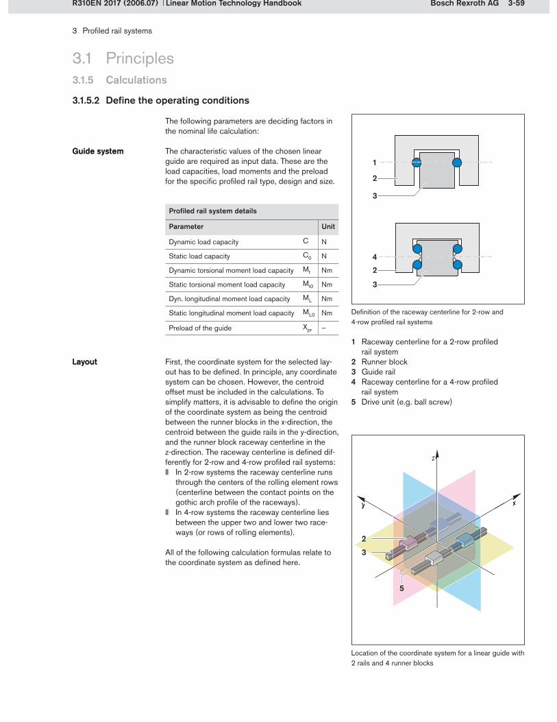
3-59Bosch Rexroth AG
xy xy
z
3
42
3
1
2
5
2
3
3 Profiled rail systems
Linear Motion Technology HandbookR310EN 2017 (2006.07)
3.1.5.2 Define the operating conditions
The following parameters are deciding factors in the nominal life calculation:
The characteristic values of the chosen linear guide are required as input data. These are the load capacities, load moments and the preload for the specific profiled rail type, design and size.
Guide systemGuide system
First, the coordinate system for the selected lay-out has to be defined. In principle, any coordinate system can be chosen. However, the centroid offset must be included in the calculations. To simplify matters, it is advisable to define the origin of the coordinate system as being the centroid between the runner blocks in the x-direction, the centroid between the guide rails in the y-direction, and the runner block raceway centerline in the z-direction. The raceway centerline is defined dif-ferently for 2-row and 4-row profiled rail systems:
In 2-row systems the raceway centerline runs through the centers of the rolling element rows (centerline between the contact points on the gothic arch profile of the raceways).In 4-row systems the raceway centerline lies between the upper two and lower two race-ways (or rows of rolling elements).
All of the following calculation formulas relate to the coordinate system as defined here.
LayoutLayout
Location of the coordinate system for a linear guide with 2 rails and 4 runner blocks
3.1 Principles3.1.5 Calculations
Profiled rail system details
Parameter Unit
Dynamic load capacity C N
Static load capacity C0 N
Dynamic torsional moment load capacity Mt Nm
Static torsional moment load capacity Mt0 Nm
Dyn. longitudinal moment load capacity ML Nm
Static longitudinal moment load capacity ML0 Nm
Preload of the guide Xpr –
Definition of the raceway centerline for 2-row and 4-row profiled rail systems
Raceway centerline for a 2-row profiled rail systemRunner blockGuide railRaceway centerline for a 4-row profiled rail systemDrive unit (e.g. ball screw)
1�
2�3�4�
5�

3-60 Bosch Rexroth AG
y x
L W
LS
m
z Sz S
xS
yS
L z
Ly
!
"
z
21
3
3 Profiled rail systems
Linear Motion Technology Handbook R310EN 2017 (2006.07)
3.1 Principles3.1.5 Calculations
The layout of the guide system is described by the centroid distances of the guide rails LS and the runner blocks LW .
All forces acting on the system along the x-direc-tion must be applied via the drive unit, e.g. ball screw. Consequently, the location of the drive unit relative to the origin of the coordinate system is included in the calculation as the dimensions Ly and Lz .
If the system is not installed horizontally, the orientation must be specified using the angles and . The mass of the carriage assembly and the location of its center of gravity are also required.
Layout of a linear guide with 2 rails and 4 runner blocks
Drive unit (e.g. ball screw)Guide railRunner block
1�2�3�
Layout details
Parameter Unit
Distance between runner blocks LW mm
Distance between guide rails LS mm
Location of drive unit in the y-direction
Ly mm
Location of drive unit in the z-direction
Lz mm
Angular location of the guide relative to the X-axis
°
Angular location of the guide relative to the Y-axis
°
Location of center of gravity in the x-direction
xS mm
Location of center of gravity in the y-direction
yS mm
Location of center of gravity in the z-direction
zS mm
Mass m kg
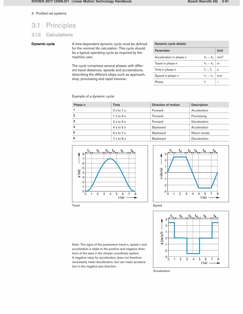
3-61Bosch Rexroth AG
3 Profiled rail systems
Linear Motion Technology HandbookR310EN 2017 (2006.07)
A time-dependent dynamic cycle must be defined for the nominal life calculation. This cycle should be a typical operating cycle as required by the machine user.
The cycle comprises several phases with differ-ent travel distances, speeds and accelerations, describing the different steps such as approach, stop, processing and rapid traverse.
Dynamic cycleDynamic cycle
Note: The signs of the parameters travel s, speed v and acceleration a relate to the positive and negative direc-tions of the axes in the chosen coordinate system.A negative value for acceleration does not therefore necessarily mean deceleration, but can mean accelera-tion in the negative axis direction.
Example of a dynamic cycle:
Phase n Time Direction of motion Description1 0 s to 1 s Forward Acceleration
2 1 s to 3 s Forward Processing
3 3 s to 4 s Forward Deceleration
4 4 s to 5 s Backward Acceleration
5 5 s to 7 s Backward Return stroke
6 7 s to 8 s Backward Deceleration
3.1 Principles3.1.5 Calculations
Travel Speed
Dynamic cycle details
Parameter Unit
Acceleration in phase n a1 ... an m/s2
Travel in phase n s1 ... sn m
Time in phase n t1 ... tn s
Speed in phase n v1 ... vn m/s
Phase n –
Acceleration
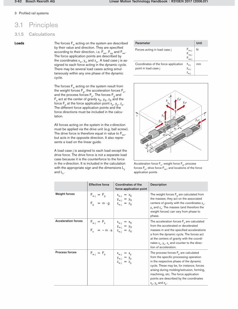
3-62 Bosch Rexroth AG
y x
L zLy
z p
xp
FpxFpz
Fg
Fa yp
Fpy
z S
xS
yS
Fwx
z
3 Profiled rail systems
Linear Motion Technology Handbook R310EN 2017 (2006.07)
The forces Fw acting on the system are described by their value and direction. They are specified according to their direction, i.e. Fwx , Fwy and Fwz . The force application points are described by the coordinates xw , yw and zw . A load case j is as-signed to each force acting in the dynamic cycle. There may be several load cases acting simul-taneously within any one phase of the dynamic cycle.
LoadsLoads
3.1 Principles3.1.5 Calculations
Effective force Coordinates of the force application point
Description
Weight forces Fw, j = Fg
Fg = m . g
xw, j = xSyw, j = ySzw, j = zS
The weight forces Fg are calculated from the masses; they act on the associated centers of gravity with the coordinates xs , ys and zs . The masses (and therefore the weight forces) can vary from phase to phase.
Acceleration forces Fw, j = Fa
Fa = – m . a
xw, j = xSyw, j = ySzw, j = zS
The acceleration forces Fa are calculated from the accelerated or decelerated masses m and the specified accelerations a from the dynamic cycle. The forces act at the centers of gravity with the coordi-nates xs , ys , zs and counter to the direc-tion of acceleration.
Process forces Fw, j = Fp xw, j = xpyw, j = ypzw, j = zp
The process forces Fp are calculated from the specific processing operation in the respective phase of the dynamic cycle. These may be, for instance, forces arising during molding/extrusion, forming, machining, etc. The force application points are described by the coordinates xp , yp and zp .
The forces Fw acting on the system result from the weight forces Fg , the acceleration forces Fa , and the process forces Fp . The forces Fg and Fa act at the center of gravity xS , yS , zS and the force Fp at the force application point xp , yp , zp . The different force application points and the force directions must be included in the calcu-lation.
All forces acting on the system in the x-direction must be applied via the drive unit (e.g. ball screw). The drive force is therefore equal in value to Fwx , but acts in the opposite direction. It also repre-sents a load on the linear guide.
A load case j is assigned to each load except the drive force. The drive force is not a separate load case because it is the counterforce to the force in the x-direction. It is included in the calculation with the appropriate sign and the dimensions Ly and Lz .
Acceleration force Fa , weight force Fg , process forces Fp , drive force Fwx , and locations of the force application points
Parameter Unit
Forces acting in load case j Fwx, j Fwy, j Fwz, j
N
Coordinates of the force application point in load case j
xw, j yw, j zw, j
mm
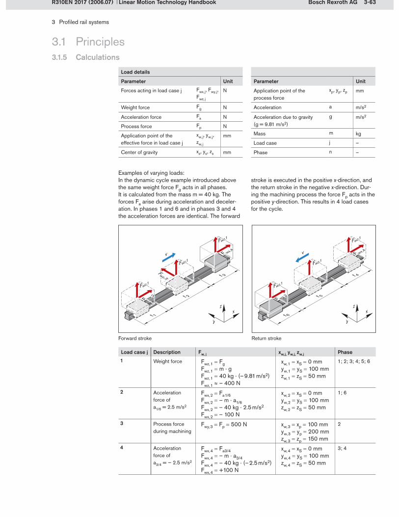
3-63Bosch Rexroth AG
t 3
t 2
t 1x
y
z
F wx,4
Fwz,1
v
F wx,2
Fwz,1
Fwz,1
Fwy,3 t 4
t 5
t 6x
y
z
F wx,4
Fwz,1
F wx,2
Fwz,1
Fwz,1
v
3 Profiled rail systems
Linear Motion Technology HandbookR310EN 2017 (2006.07)
3.1 Principles3.1.5 Calculations
In the dynamic cycle example introduced above the same weight force Fg acts in all phases. It is calculated from the mass m = 40 kg. The forces Fa arise during acceleration and deceler- ation. In phases 1 and 6 and in phases 3 and 4 the acceleration forces are identical. The forward
stroke is executed in the positive x-direction, and the return stroke in the negative x-direction. Dur-ing the machining process the force Fp acts in the positive y-direction. This results in 4 load cases for the cycle.
Load case j Description Fw, j xw, j, yw, j, zw, j Phase1 Weight force Fwz, 1 Fg
Fwz, 1 m . gFwz, 1 40 kg . (– 9.81 m/s2)Fwz, 1 – 400 N
xw, 1 xS 0 mmyw, 1 yS 100 mmzw, 1 zS 50 mm
1; 2; 3; 4; 5; 6
2 Acceleration force ofa1/6 = 2.5 m/s2
Fwx, 2 Fa 1/6Fwx, 2 – m . a1/6Fwx, 2 – 40 kg . 2.5 m/s2
Fwx, 2 – 100 N
xw, 2 xS 0 mmyw, 2 yS 100 mmzw, 2 zS 50 mm
1; 6
3 Process force during machining
Fwy, 3 Fp 500 N xw, 3 xp 100 mmyw, 3 yp 200 mmzw, 3 zp 150 mm
2
4 Acceleration force of a3/4 = – 2.5 m/s2
Fwx, 4 Fa3/4Fwx, 4 – m . a3/4Fwx, 4 – 40 kg . (– 2.5 m/s2)Fwx, 4 +100 N
xw, 4 xS 0 mmyw, 4 yS 100 mmzw, 4 zS 50 mm
3; 4
Forward stroke Return stroke
Examples of varying loads:
Load details
Parameter Unit
Forces acting in load case j Fwx, j, Fwy, j, Fwz, j
N
Weight force Fg N
Acceleration force Fa N
Process force Fp N
Application point of the effective force in load case j
xw, j, yw, j, zw, j
mm
Center of gravity xs, ys, zs mm
Parameter Unit
Application point of the process force
xp, yp, zp mm
Acceleration a m/s2
Acceleration due to gravity (g = 9.81 m/s2)
g m/s2
Mass m kg
Load case j –
Phase n –

3-64 Bosch Rexroth AG
xy
z
Mx
M z
My
Fz
Fy
3 Profiled rail systems
Linear Motion Technology Handbook R310EN 2017 (2006.07)
3.1 Principles3.1.5 Calculations
3.1.5.3 Loads due to forces and moments
The forces acting on the system are distributed among the runner blocks according to the layout of the system. The loads due to forces and mo-ments resulting from the forces acting on the sys-tem have to be calculated for each runner block when performing the nominal life calculation.
All load calculations assume an infinitely rigid mounting base and an infinitely rigid attachment.
Forces and moments acting on the runner block
The following table shows the layouts that are most commonly used in practice along with the runner block loads that have to be calculated in each case.
Scenario Layout Forces Moments
in z-direction
in y-direction
about the X-axis
about the Y-axis
about the Z-axis
Lift-off/down force
Side load Torsional moment
Longitudi-nal moment
Longitudi-nal moment
1 1 rail1 runner block
Fz Fy Mx My Mz
2 1 rail2 runner blocks
Fz Fy Mx – –
3 2 rails2 runner blocks
Fz Fy – My Mz
4 2 rails4 runner blocks
Fz Fy – – –
5 2 rails6 runner blocks
Fz Fy – – –
6 2 rails8 runner blocks
Fz Fy – – –
Load on a single runner block due to forces and moments
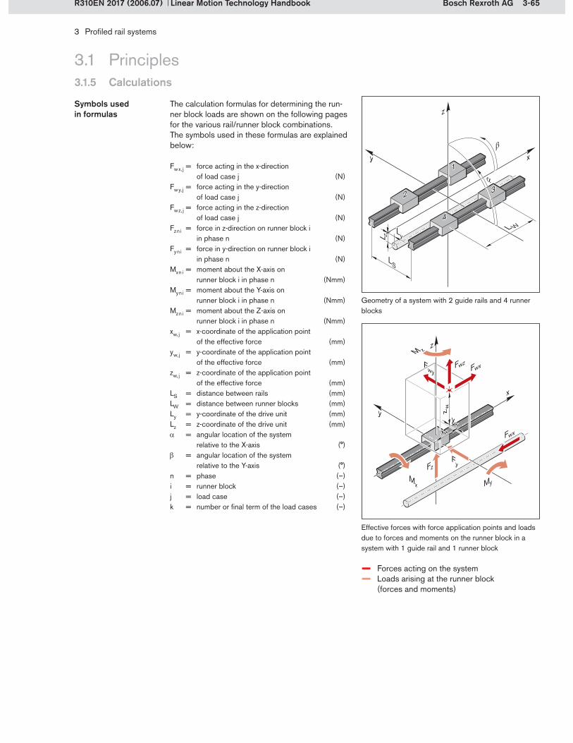
3-65Bosch Rexroth AG
L W
LS
!
"
xy
z
1
2 3
4
L z
Ly
y
x
FzFy
z w
xw
yw
Fwx
zM z
MyMx
Fwy FwxFwz
3 Profiled rail systems
Linear Motion Technology HandbookR310EN 2017 (2006.07)
3.1 Principles3.1.5 Calculations
The calculation formulas for determining the run-ner block loads are shown on the following pages for the various rail/runner block combinations. The symbols used in these formulas are explained below:
Symbols used in formulas
Fw x, j = force acting in the x-direction of load case j (N)
Fw y, j = force acting in the y-direction of load case j (N)
Fw z, j = force acting in the z-direction of load case j (N)
Fz n i = force in z-direction on runner block i in phase n (N)
Fy n i = force in y-direction on runner block i in phase n (N)
Mx n i = moment about the X-axis on runner block i in phase n (Nmm)
My n i = moment about the Y-axis on runner block i in phase n (Nmm)
Mz n i = moment about the Z-axis on runner block i in phase n (Nmm)
xw, j = x-coordinate of the application point of the effective force (mm)
yw, j = y-coordinate of the application point of the effective force (mm)
zw, j = z-coordinate of the application point of the effective force (mm)
LS = distance between rails (mm)LW = distance between runner blocks (mm)Ly = y-coordinate of the drive unit (mm)Lz = z-coordinate of the drive unit (mm) = angular location of the system
relative to the X-axis (°) = angular location of the system
relative to the Y-axis (°)n = phase (–)i = runner block (–)j = load case (–)k = number or final term of the load cases (–)
Geometry of a system with 2 guide rails and 4 runner blocks
Effective forces with force application points and loads due to forces and moments on the runner block in a system with 1 guide rail and 1 runner block
– Forces acting on the system– Loads arising at the runner block (forces and moments)
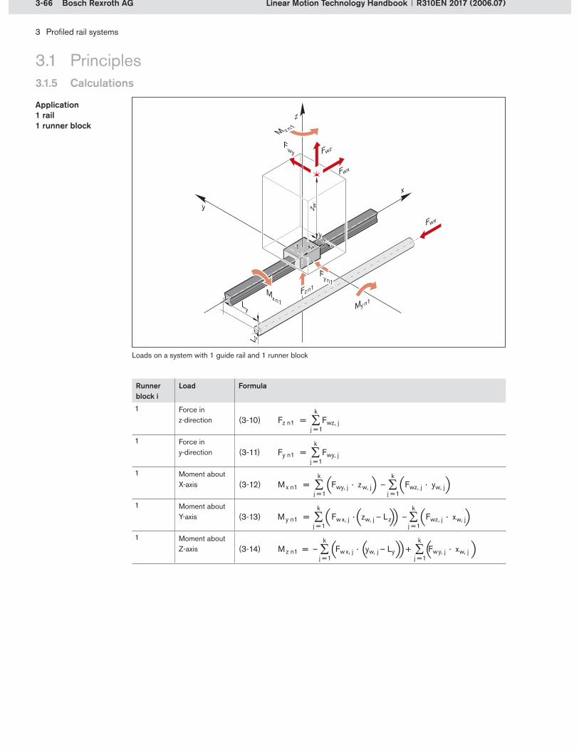
3-66 Bosch Rexroth AG
1
y
x
Fy n1
Fz n1
L z
Lyz w
xw
yw
Fwy
Fwx
Fwz
Fwx
z
M z n1
My n1M
x n1
3 Profiled rail systems
Linear Motion Technology Handbook R310EN 2017 (2006.07)
3.1 Principles3.1.5 Calculations
Loads on a system with 1 guide rail and 1 runner block
Runner block i
Load Formula
1 Force in z-direction Fz n 1 = Fwz, j
k
j = 1
1 Force in y-direction Fy n 1 = Fwy, j
k
j = 1
1 Moment about X-axis Mx n 1 = Fwy, j · zw, j – Fwz, j · yw, j
k
j = 1
k
j = 1
1 Moment about Y-axis My n 1 = Fw x, j · zw, j – Lz – Fwz, j · xw, j
k
j = 1
k
j = 1
1 Moment about Z-axis Mz n 1 = – Fw x, j · yw, j – Ly + Fwy, j · xw, j
k
j = 1
k
j = 1
Application 1 rail1 runner block
(3-10)
(3-11)
(3-12)
(3-13)
(3-14)

3-67Bosch Rexroth AG
1
2
L W
Fzn1
Fzn2
xy
Fyn1
Fyn2
L zLy
Fwy
Fwx
Fwz
Mxn1/2
Fwx
z w
xwyw
z
3 Profiled rail systems
Linear Motion Technology HandbookR310EN 2017 (2006.07)
Application 1 rail2 runner blocks
Runner block i
Load Formula
1 Force in z-direction
k
j = 1Fz n 1 = –
Fwz, j
k
j = 1
k
j = 1Fwx, j · zw, j – Lz – Fwz, j · xw, j
2 L W
2 Force in z-direction
k
j = 1Fz n 2 = +
Fwz, j
k
j = 1
k
j = 1Fwx, j · zw, j – Lz – Fwz, j · xw, j
2 L W
1 Force in y-direction
k
j = 1Fy n 1 = –
Fwy, j
k
j = 1
k
j = 1Fwx, j · yw, j – Ly – Fwy, j · xw, j
2 L W
2 Force in y-direction
k
j = 1Fy n 2 = +
Fwy, j
k
j = 1
k
j = 1Fwx, j · yw, j – Ly – Fwy, j · xw, j
2 L W
1/2 Moment about X-axis
Mx n 1 = Mx n 2 =
k
j = 1
k
j = 1Fwy, j · zw, j – Fwz, j · yw, j
2
Loads on a system with 1 guide rail and 2 runner blocks
3.1 Principles3.1.5 Calculations
(3-15)
(3-16)
(3-17)
(3-18)
(3-19)

3-68 Bosch Rexroth AG
Fz n2
Fz n1
Fy n2
1
2
LS
x
y
L z
Lyz w
xw
yw
Mz n1/2
My n1/2
Fwy
Fwx
Fwz
FwxFy n1
z
3 Profiled rail systems
Linear Motion Technology Handbook R310EN 2017 (2006.07)
3.1 Principles3.1.5 Calculations
Application 2 rails2 runner blocks
Runner block i
Load Formula
1 Force in z-direction
k
j = 1
k
j = 1Fwy, j · zw, j – Fwz, j · yw, j
LS
k
j = 1Fz n 1 = –
Fwz, j
2
2 Force in z-direction
k
j = 1
k
j = 1Fwy, j · zw, j – Fwz, j · yw, j
LS
k
j = 1Fz n 2 = +
Fwz, j
2
1/2 Force in y-direction
1/2 Moment about Y-axis
My n 1 = My n 2 =
k
j = 1
k
j = 1Fwx, j · zw, j – Lz – Fwz, j · xw, j
2
1/2 Moment about Z-axis
Mz n 1 = Mz n 2 =
k
j = 1
k
j = 1Fwx, j · yw, j – Ly + Fwy, j · yw, j –
2
Loads on a system with 2 guide rails and 2 runner blocks
(3-20)
(3-21)
(3-23)
(3-22)
(3-24)

3-69Bosch Rexroth AG
1
23
4Fz n2
Fz n4
Fz n3
Fz n1
L W
LS
x
y
L z
Ly
yw
xw
z w
Fwy
Fwx
Fwz
Fwx
z
3 Profiled rail systems
Linear Motion Technology HandbookR310EN 2017 (2006.07)
3.1 Principles3.1.5 Calculations
Applications with 2 rails and 4 runner blocks are the most common of all layouts. This layout will therefore be described in more detail.
Application 2 rails4 runner blocks
i Formula1 k
j = 1Fz n 1 = + +
Fwz, j
k
j = 1
k
j = 1Fwz, j · yw, j – Fwy, j · zw, j
4 2 · L S
k
j = 1
k
j = 1Fwz, j · xw, j – Fwx, j · zw, j – L z
2 · L W
2 k
j = 1Fz n 2 = + +
Fwz, j
k
j = 1
k
j = 1Fwz, j · yw, j – Fwy, j · zw, j
4 2 · L S
k
j = 1
k
j = 1Fwx, j · zw, j – L z – Fwz, j · x w, j
2 · L W
3 k
j = 1Fz n 3 = + +
Fwz, j
k
j = 1
k
j = 1Fwy, j · zw, j – Fwz, j · yw, j
4 2 · L S
k
j = 1
k
j = 1Fwz, j · xw, j – Fwx, j · zw, j – L z
2 · L W
4 k
j = 1Fz n 4 = + +
Fwz, j
k
j = 1
k
j = 1Fwy, j · zw, j – Fwz, j · yw, j
4 2 · L S
k
j = 1
k
j = 1Fwx, j · zw, j – L z – Fwz, j · x w, j
2 · L W
The external loads Fz n i acting on the runner blocks i (1 to 4) in the z-direction in a phase n are calculated using the following formulas.
Loads in z-direction
Loads on a system with 2 guide rails and 4 runner blocks
(3-25)
(3-26)
(3-27)
(3-28)

3-70 Bosch Rexroth AG
1
23
4
L W
LS
x
y
L z
Ly
Fy n2
Fy n4
Fy n3
Fy n1yw
xw
z w
Fwy
Fwx
Fwz
Fwx
z
3 Profiled rail systems
Linear Motion Technology Handbook R310EN 2017 (2006.07)
3.1 Principles3.1.5 Calculations
The external loads Fy n i acting on the runner blocks i (1 to 4) in the y-direction in a phase n are calculated using the following formulas.
Loads in y-direction
i Formula13
k
j = 1Fy n 1 = Fy n 3 = +
Fwy, j
4
k
j = 1
k
j = 1Fwy, j · xw, j – Fwx, j · yw, j – L y
2 · L W
24
k
j = 1Fy n 2 = Fy n 4 = –
Fwy, j
4
k
j = 1
k
j = 1Fwy, j · xw, j – Fwx, j · yw, j – L y
2 · L W
Loads on a system with 2 guide rails and 4 runner blocks
(3-29)
(3-30)

3-71Bosch Rexroth AG
y x
z
Fz n i
i
Fy n i
3 Profiled rail systems
Linear Motion Technology HandbookR310EN 2017 (2006.07)
3.1.5.4 Combined equivalent load on bearing
3.1 Principles3.1.5 Calculations
The loads calculated for the individual runner blocks (forces Fx , Fy , Fz and moments Mx , My , Mz) are combined into comparative loads for each runner block. These comparative loads are called the combined equivalent loads on the bearing.
For the calculation of loads on runner blocks, a distinction is made between horizontal loads (y-direction) and vertical loads (z-direction), similar to the distinction between radial and axial forces in rotary anti-friction bearings. For loads acting in a direction other than the main directions described above, the forces must be resolved. Runner blocks can take up moments as well as forces. If several runner blocks are mounted one behind the other at close intervals on a guide rail, this must be taken into account when calculating the load on the bearing.
The load cases are therefore as follows:Vertical and horizontal forcesVertical and horizontal forces combined with momentsConsideration of closely spaced runner blocks (using contact factor fC)
Main directions of loading Definition of main load directions
Vertical and horizontal forces
(3-31)
Fcomb n i = combined equivalent load on bearing for runner block i (N)
Fz n i = force in z-direction on runner block i during phase n (N)
Fy n i = force in y-direction on runner block i during phase n (N)
For external loads acting on a runner block i in phase n due to vertical forces Fz and horizontal forces Fy , a comparative load is required for the nominal life calculation. This combined equivalent load on the bearing is the sum of the absolute values of the forces Fz and Fy . The structure of the profiled rail systems allows this simplified calculation.
Vertical and horizontal forces

3-72 Bosch Rexroth AG
xy
z
iM
x n i
M z n i
My n i
Fz n i
Fy n i
3 Profiled rail systems
Linear Motion Technology Handbook R310EN 2017 (2006.07)
3.1 Principles3.1.5 Calculations
For an external load acting on a runner block i in phase n due to vertical and horizontal forces com-bined with moments about the X, Y and Z-axes, the combined equivalent load on the bearing is calculated using the formulas given below.
Since it is assumed that the adjoining structure is infinitely rigid, moments can only occur in three specific layouts. The only situation in which mo-ments can be taken up in all directions is a layout with just one runner block (see section 3.1.5.3).
Vertical and horizontal forces combined with moments
Layout Formula
1 rail 1 runner block
Mx n iMt
Fcomb n i = Fy n i + Fz n i + C · + C · + C ·My n iML
Mz n iML
1 rail 2 runner blocks
Fcomb n i = Fy n i + Fz n i + C · Mx n iMt
2 rails 2 runner blocks
Fcomb n i = Fy n i + Fz n i + C · + C ·Myn iML
Mz n iML
Combination of force and moment loads
Fcomb n i = combined equivalent load on bearing for runner block i during phase n (N)
Fy n i = force in y-direction acting on runner block i during phase n (N)
Fz n i = force in z-direction acting on runner block i during phase n (N)
Mx n i = torsional moment about the X-axis acting on runner block i during phase n (Nm)
My n i = longitudinal moment about the Y-axis acting on runner block i during phase n (Nm)
Mz n i = longitudinal moment about the Z-axis acting on runner block i during phase n (Nm)
(3-32)
(3-33)
(3-34)
C = dynamic load capacity (N)Mt = dynamic torsional moment
load capacity (Nm)ML = dynamic longitudinal moment
load capacity (Nm)

3-73Bosch Rexroth AG
Fcomb n i = · Fy n i + Fz n i 1fC
3 Profiled rail systems
Linear Motion Technology HandbookR310EN 2017 (2006.07)
3.1 Principles3.1.5 Calculations
If runner blocks are mounted on a guide rail one behind the other with a center-to-center dis-tance LW of less than 1.5 times the runner block length LFW , this is likely to result in an unequal distribution of the load between the runner blocks. The reasons for this are inaccuracies in the mounting surfaces and the manufacturing tolerances of the guide components.
In such a case, the contact factor fC is included when calculating the load on the bearing. The contact factor depends on the number of closely spaced runner blocks. It is a statistical value. In normal operation, with sufficient space between the runner blocks, the contact factor is fC = 1.
The contact factor fC can be calculated using the following formula:
Closely spaced runner blocks
Contact factor
Runner block length and center-to-center distance between runner blocks
(3-35)
fC = contact factor (–)i = number of closely spaced runner blocks (–)
Number of runner blocks Contact factor fC1 1
2 0.81
3 0.72
4 0.66
5 0.62
Because the contact factor fC increases the equivalent load on the bearing, the nominal life will be reduced to a greater or lesser extent, depending on the load case.
Fcomb n i = combined equivalent load on bearing for runner block i during phase n (N)
Fy n i = force in y-direction acting on runner block i during phase n (N)
Fz n i = force in z-direction acting on runner block i during phase n (N)
For situations with closely spaced runner blocks, the formulas (3-32) to (3-34) taking account of moment loads are also multiplied with the inverse of fC .
Moment loads
(3-36)
fC = i0.7
i
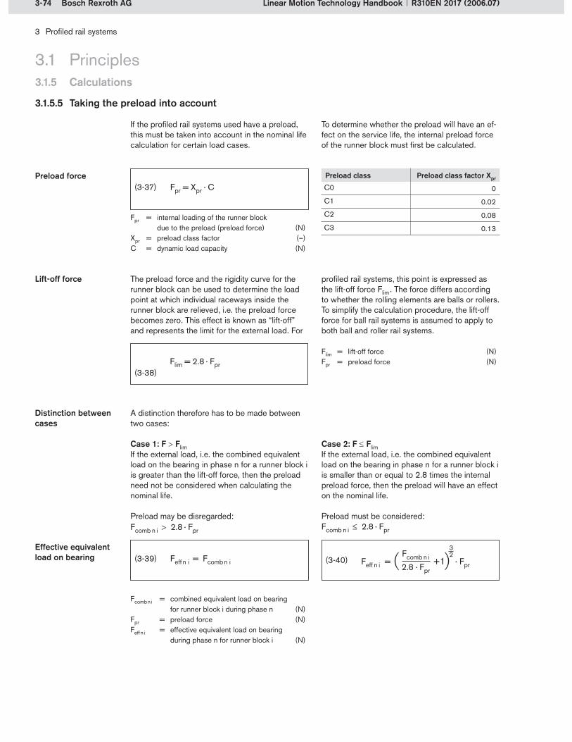
3-74 Bosch Rexroth AG
3 Profiled rail systems
Linear Motion Technology Handbook R310EN 2017 (2006.07)
3.1.5.5 Taking the preload into account
If the profiled rail systems used have a preload, this must be taken into account in the nominal life calculation for certain load cases.
(3-37)
Fpr = internal loading of the runner block due to the preload (preload force) (N)
Xpr = preload class factor (–)C = dynamic load capacity (N)
Preload class Preload class factor Xpr
C0 0
C1 0.02
C2 0.08
C3 0.13
The preload force and the rigidity curve for the runner block can be used to determine the load point at which individual raceways inside the runner block are relieved, i.e. the preload force becomes zero. This effect is known as “lift-off” and represents the limit for the external load. For
Lift-off force profiled rail systems, this point is expressed as the lift-off force Flim . The force differs according to whether the rolling elements are balls or rollers. To simplify the calculation procedure, the lift-off force for ball rail systems is assumed to apply to both ball and roller rail systems.
Flim = lift-off force (N)Fpr = preload force (N)
To determine whether the preload will have an ef-fect on the service life, the internal preload force of the runner block must first be calculated.
3.1 Principles3.1.5 Calculations
A distinction therefore has to be made between two cases:
Case 1: F FlimIf the external load, i.e. the combined equivalent load on the bearing in phase n for a runner block i is greater than the lift-off force, then the preload need not be considered when calculating the nominal life.
Preload may be disregarded:
Distinction between cases
Case 2: F FlimIf the external load, i.e. the combined equivalent load on the bearing in phase n for a runner block i is smaller than or equal to 2.8 times the internal preload force, then the preload will have an effect on the nominal life.
Preload must be considered:
Fcomb n i = combined equivalent load on bearing for runner block i during phase n (N)
Fpr = preload force (N)Feff n i = effective equivalent load on bearing
during phase n for runner block i (N)
(3-38)
(3-39)Effective equivalent load on bearing (3-40)
Flim = 2.8 · Fpr
Fcomb n i > 2.8 · Fpr Fcomb n i ! 2.8 · Fpr
Feff n i = +1 · Fpr Fcomb n i2.8 · Fpr
32
Preload force

3-75Bosch Rexroth AG
F (N
)
s (m)
s1 s2
F3
F2
F1
Fm
s3
3 Profiled rail systems
Linear Motion Technology HandbookR310EN 2017 (2006.07)
3.1 Principles3.1.5 Calculations
3.1.5.6 Equivalent dynamic load on bearing
The equivalent dynamic load on the bearing Fm must always be calculated when varying process forces or varying weight forces are involved, or when the system is to be accelerated and de-celerated. Calculation of the equivalent dynamic load combines the loads on a runner block i in the individual phases n to produce a resulting com-parative load for the entire dynamic cycle. If the load on the bearing varies in steps, the equivalent dynamic load on the bearing is calculated in a manner similar to that for rotary anti-friction bearings.
Varying forces
For stepwise variations in loads, the equivalent dynamic load on the bearing is calculated accord-ing to discrete travel steps.
Calculation of discrete travel steps for phase n:
Stepwise variations in bearing loads
(3-41) qs1 ... qsn = discrete travel steps for phases 1 ... n (%)
s1 ... sn = travel in phases 1 ... n (mm)s = total travel (mm)n = phase (–)
(3-42)
Example of stepwise variations in loading
For each runner block i and each motion phase n, the individual loads are calculated as described in the preceding sections. These individual loads are then multiplied by the percentages for the dis-crete travel steps. Finally, formula (3-43) is used to calculate the equivalent load on the runner block throughout the entire motion cycle.
Equivalent dynamic loading of a runner block
Fm i = equivalent dynamic load on bearing for runner block i (N)
Feff 1 i ... Feff n i = effective equivalent load on bearing for runner block i in phases 1 ... n (N)
qs1 ... qsn = discrete travel steps for phases 1 ... n (%)
s1 ... sn = travel in phases 1 ... n (mm)s = total travel (mm)
(3-43)
p = 3 for ball rail guidesp = 10/3 for roller rail guides
-- Actual force profile– Effective equivalent load in phases 1 ... n– Equivalent dynamic load for entire cycle
qsn = · 100%sns

3-76 Bosch Rexroth AG
Li = · 105 m CFi
p
3 Profiled rail systems
Linear Motion Technology Handbook R310EN 2017 (2006.07)
3.1.5.7 Life expectancy
The calculated service life which an individual linear motion rolling bearing, or a group of ap-parently identical linear motion rolling bearings operating under the same conditions, can attain with a 90% probability, with contemporary,
Nominal life
The nominal life of a runner block i is calculated using the following formula. The result is the expected travel life in meters.
Li = nominal life of the runner block i (m)C = dynamic load capacity (N)Fi = load on bearing of the runner block i (N)(3-44)
p = 3 for ball rail guidesp = 10/3 for roller rail guides
Load case Force Fi Nominal life Description SectionForce loads Fy n i
Fz n i Li = · 105 m CFy n i
p A constant force acting in the main load direction on the runner block i
3.1.5.3
Combined equivalent load on bearing
Fcomb n iLi = · 105 m C
Fcomb n i
p A constant force acting at a certain angle or a constant moment acting on the runner block i
3.1.5.4
Taking preload into account with the effective equivalent load on bearing
Feff n iLi = · 105 m C
Feff n i
p Effect of preload and a constant load on bearing on runner block i
3.1.5.5
Equivalent dynamic load on bearing Fm iLi = · 105 m C
Fm i
p Varying load on bearing acting in n phases on runner block i
3.1.5.6
Depending on the load case, the following forces can be factored into the formula.
Distinction according to load case
commonly used materials and manufacturing quality under conventional operating conditions (per ISO 14728 Part 1).
3.1 Principles3.1.5 Calculations
If the stroke length sstroke and the stroke fre-quency nstroke are constant throughout the service life, the service life in operating hours can be calculated as follows:
Nominal life in operating hours
Lh i = nominal life (h)Li = nominal life (m)sstroke = stroke length (m)nstroke = stroke frequency
(full cycles per minute) (min–1)
(3-49)
(3-45)
(3-46)
(3-47)
(3-48)
Lh i = L i
2 · sstroke · nstroke · 60
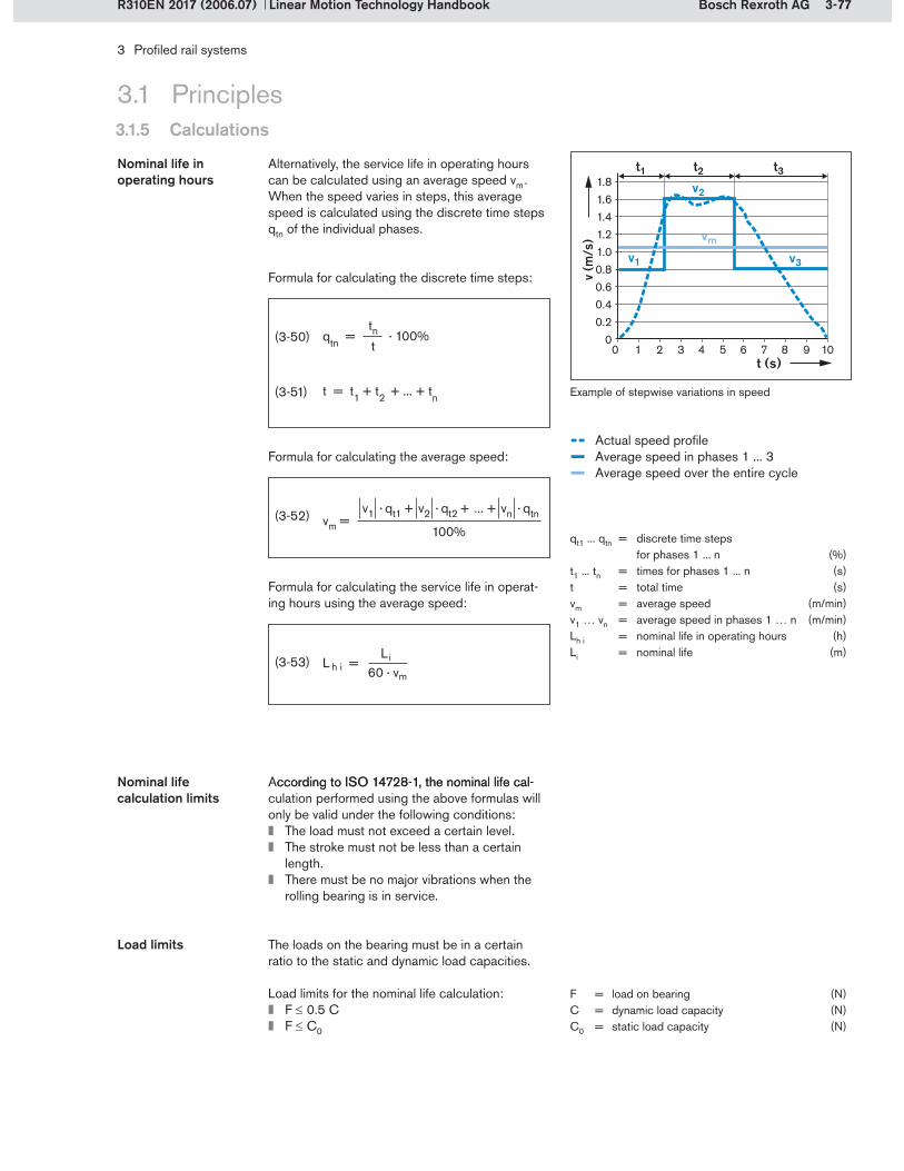
3-77Bosch Rexroth AG
3 Profiled rail systems
Linear Motion Technology HandbookR310EN 2017 (2006.07)
3.1 Principles3.1.5 Calculations
Alternatively, the service life in operating hours can be calculated using an average speed vm . When the speed varies in steps, this average speed is calculated using the discrete time steps qtn of the individual phases.
qt1 ... qtn = discrete time steps for phases 1 ... n (%)
t1 ... tn = times for phases 1 ... n (s)t = total time (s)vm = average speed (m/min)v1 … vn = average speed in phases 1 … n (m/min)Lh i = nominal life in operating hours (h)Li = nominal life (m)
(3-50)
Example of stepwise variations in speed(3-51)
(3-52)
(3-53)
According to ISO 14728-1, the nominal life cal-ccording to ISO 14728-1, the nominal life cal-culation performed using the above formulas will only be valid under the following conditions:
The load must not exceed a certain level.The stroke must not be less than a certain length.There must be no major vibrations when the rolling bearing is in service.
Nominal life calculation limits
F = load on bearing (N)C = dynamic load capacity (N)C0 = static load capacity (N)
Nominal life in operating hours
The loads on the bearing must be in a certain ratio to the static and dynamic load capacities.
Load limits for the nominal life calculation:F 0.5 CF C0
Load limits
-- Actual speed profile– Average speed in phases 1 ... 3– Average speed over the entire cycle
Formula for calculating the discrete time steps:
Formula for calculating the average speed:
Formula for calculating the service life in operat-ing hours using the average speed:
qtn = · 100%tnt
1.81.61.41.21.00.80.60.40.2
00 1 2 3 4 5 6 7 8 109
v (m
/s)
t (s)
t1 t2
v1
v2
v3
vm
t3
vm = v1 · qt1 + v2 · qt2 + ... + vn · qtn
100%

3-78 Bosch Rexroth AG
L na i = a1 · · 105 m CFi
p
3 Profiled rail systems
Linear Motion Technology Handbook R310EN 2017 (2006.07)
The probability that a guide will attain the nominal life L is 90%. If a higher life expectancy is desired, the calculations are performed using the modi-fied life expectancy Lna . The nominal life L is then multiplied by the coefficient a1 . This coefficient stands for the probability of survival of the runner blocks and is shown in the table alongside.
Modified life expectancy
Lna i = modified life expectancy (m)C = dynamic load capacity (N)Fi = load on bearing of the runner block i (N)a1 = life expectancy coefficient (–)
(3-54)
Probability of survival (%) Lna a1
90 L10a 1
95 L5a 0.62
96 L4a 0.53
97 L3a 0.44
98 L2a 0.33
99 L1a 0.21
p = 3 for ball rail guidesp = 10/3 for roller rail guides
3.1 Principles3.1.5 Calculations
When the stroke is less than two times the run-ner block length, not all the rolling elements will undergo rolling contact in the load-bearing zone. These applications are called short-stroke ap-plications.
Stroke limit for the nominal life calculation:Lstroke 2 · LFW
Definition of short stroke:Lstroke 2 · LFW
Limitation due to short stroke
LFW = runner block length (mm)Lstroke = stroke length (mm)
If the application is a short stroke one, this must be taken into account in the nominal life calcula-tion. The expected service life will then be shorter than the nominal life. Users should contact Rexroth for assistance in calculating the service life for such applications.
Vibrations can considerably shorten the service life of a profiled rail system. If major vibrations are expected in the machine environment, users should contact Rexroth for advice.
Limitation due to vibrations
Stroke length and runner block length
LFW
Lstroke
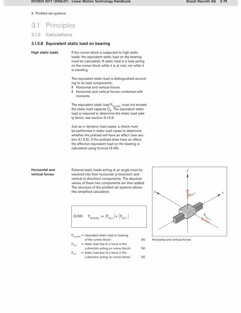
3-79Bosch Rexroth AG
y x
z
F0 z n i
i
F0 y n i
3 Profiled rail systems
Linear Motion Technology HandbookR310EN 2017 (2006.07)
3.1 Principles3.1.5 Calculations
3.1.5.8 Equivalent static load on bearing
If the runner block is subjected to high static loads, the equivalent static load on the bearing must be calculated. A static load is a load acting on the runner block while it is at rest, not while it is traveling.
The equivalent static load is distinguished accord-ing to its load components:
Horizontal and vertical forcesHorizontal and vertical forces combined with moments
The equivalent static load F0 comb i must not exceed the static load capacity C0. The equivalent static load is required to determine the static load safe-ty factor, see section 3.1.5.9.
Just as in dynamic load cases, a check must be performed in static load cases to determine whether the preload will have an effect (see sec-tion 3.1.5.5). If the preload does have an effect, the effective equivalent load on the bearing is calculated using formula (3-40).
High static loads
External static loads acting at an angle must be resolved into their horizontal (y-direction) and vertical (z-direction) components. The absolute values of these two components are then added. The structure of the profiled rail systems allows this simplified calculation.
Horizontal and vertical forces
F0 comb i = equivalent static load on bearing of the runner block i (N)
F0 y i = static load due to a force in the y-direction acting on runner block i (N)
F0 z i = static load due to a force in the z-direction acting on runner block i (N)
(3-55)
Horizontal and vertical forces

3-80 Bosch Rexroth AG
xy
z
iM
0 x i
M 0 z i
M0 y i
F0 z i
F0 y i
3 Profiled rail systems
Linear Motion Technology Handbook R310EN 2017 (2006.07)
3.1 Principles3.1.5 Calculations
F0 comb i = equivalent static load on bearing of the runner block i (N)
F0 y i = force in the y-direction acting on runner block i (N)
F0 z i = force in the z-direction acting on runner block i (N)
C0 = static load capacity (N)
M0 x i = static torsional moment about the X-axis acting on runner block i (Nm)
M0 y i = static longitudinal moment about the Y-axis acting on runner block i (Nm)
M0 z i = static longitudinal moment about the Z-axis acting on runner block i (Nm)
Mt0 = static torsional moment load capacity (Nm)ML0 = static longitudinal moment load
capacity (Nm)
The combined external static load on the bearing due to forces and moments about the X, Y and Z-axes occurs only in certain layouts (see sec-tion 3.1.5.3).
Horizontal and vertical forces combined with moments
Layout Formula
1 rail 1 runner block
M0 x iMt0
F0 comb i = F0 y i + F0 z i + C0 · + C0 · + C0 ·M0 y iML0
M0 z iML0
1 rail 2 runner blocks
M0 x iMt 0
F0 comb i = F0 y i + F0 z i + C0 ·
2 rails 2 runner blocks
M 0 y i ML0
F0 comb i = F0 y i + F0 z i + C0 · + C0 · M0 z i ML0
(3-56)
(3-57)
(3-58)
Combination of force and moment loadsThe formulas for the respective layouts of profiled rail systems are shown in the table below.

3-81Bosch Rexroth AG
C0F0 max
C0F0 comb i
S0 = = C0
Fmax
C0Feff n i
S0 = =
3 Profiled rail systems
Linear Motion Technology HandbookR310EN 2017 (2006.07)
3.1 Principles3.1.5 Calculations
3.1.5.9 Static load safety factor
The static load safety factor S0 is calculated to assure that the rolling elements and the raceways will not be subjected to impermissible loading. This calculation is based on the maximum load on the most heavily loaded runner block. For a static
load, this will be the maximum static load on the bearing FF0 max , and for a purely dynamic load, the maximum dynamic load on the bearing Fmax .
Case 1: Calculation using the maximum static load on bearing F0 max
Case 2: Calculation using the maximum dynamic load on bearing Fmax
(3-59)
S0 = static load safety factor (–)C0 = static load capacity (N)F0 max = maximum static load on bearing (N)F0 comb i = maximum equivalent static load
on bearing of the runner block i (N)
(3-60)
3.1.5.10 Example of a nominal life calculation
The system in this calculation example comprises 2 rails and 4 runner blocks. This is a very com-monly used layout. The required service life is 10,000 hours. The motion cycle to be calculated involves weight forces at the center of gravity of the mass and a process force Fp . To make the calculation example easier to understand, a simplified dynamic cycle without a return stroke is assumed.
A size 30 ball rail system was chosen as the out-come of the product selection procedure.
Step 1: Define the operating conditions
Fmax = maximum dynamic load on bearing (N)Feff n i = maximum dynamic load on bearing
in phase n on runner block i (N)
Conditions of use S0
Normal conditions of use 1) 1 ... 2
Low impact loads and vibrations 2 ... 4
Moderate impact loads and vibrations 3 ... 5
Heavy impact loads and vibrations 4 ... 6
Unknown load parameters 6 ... 15
Recommendations for the static load safety factor:
Normal conditions of use are defined in Chapter 2, section 2.4.2.4.
1)
Profiled rail system details
Feature/parameter Value
Profiled rail guide Ball rail system
Size 30
Runner block Flanged, long, standard height (FLS),
without ball chain
Part number R1653 721 20
Preload class C2
Preload class factor Xpr 0.08
Accuracy class SP
Dynamic load capacity C 40 000 N
Static load capacity C0 57 800 N
Irrespective of the static load safety factor, it must be ensured that the maximum permissible loads of the profiled rail system are not exceeded. The maximum permissible load is determined by the structural strength of the runner blocks. Values for the maximum permissible loads are indicated in the product catalogs for some of the profiled rail systems.
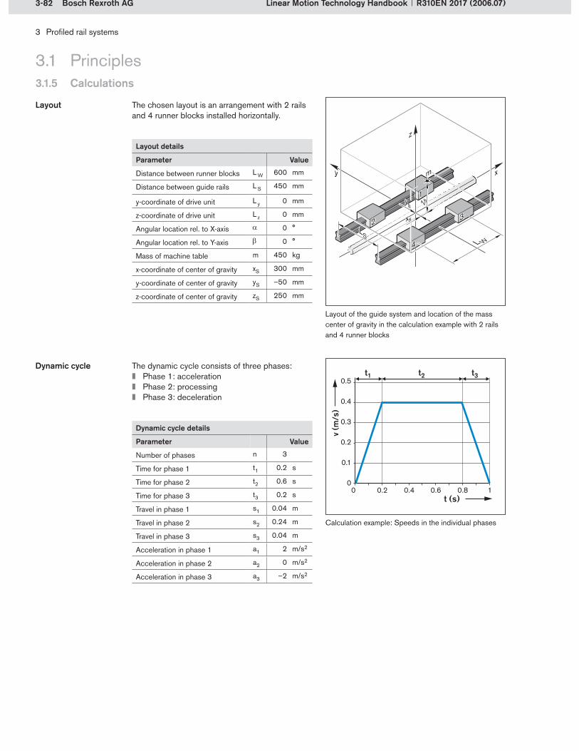
3-82 Bosch Rexroth AG
xy
z
z s
xs
ys
m
LS
1
2
4
3
L W
3 Profiled rail systems
Linear Motion Technology Handbook R310EN 2017 (2006.07)
The chosen layout is an arrangement with 2 rails and 4 runner blocks installed horizontally.
Layout
Layout of the guide system and location of the mass center of gravity in the calculation example with 2 rails and 4 runner blocks
3.1 Principles3.1.5 Calculations
Layout details
Parameter Value
Distance between runner blocks L W 600 mm
Distance between guide rails L S 450 mm
y-coordinate of drive unit L y 0 mm
z-coordinate of drive unit L z 0 mm
Angular location rel. to X-axis 0 °
Angular location rel. to Y-axis 0 °
Mass of machine table m 450 kg
x-coordinate of center of gravity xS 300 mm
y-coordinate of center of gravity yS –50 mm
z-coordinate of center of gravity zS 250 mm
Calculation example: Speeds in the individual phases
The dynamic cycle consists of three phases:Phase 1: accelerationPhase 2: processingPhase 3: deceleration
Dynamic cycle
Dynamic cycle details
Parameter Value
Number of phases n 3
Time for phase 1 t1 0.2 s
Time for phase 2 t2 0.6 s
Time for phase 3 t3 0.2 s
Travel in phase 1 s1 0.04 m
Travel in phase 2 s2 0.24 m
Travel in phase 3 s3 0.04 m
Acceleration in phase 1 a1 2 m/s2
Acceleration in phase 2 a2 0 m/s2
Acceleration in phase 3 a3 –2 m/s2
0.5
0.4
0.3
0.2
0.1
00 0.2 0.4 0.6 0.8 1
v (m
/s)
t (s)
t1 t2 t3

3-83Bosch Rexroth AG
3 Profiled rail systems
Linear Motion Technology HandbookR310EN 2017 (2006.07)
3.1 Principles3.1.5 Calculations
Calculate the discrete travel steps qsn using formulas (3-42) and (3-41):Discrete travel steps
Calculate the discrete time steps qtn using formulas (3-51) and (3-50):Discrete time steps
Calculate the average speeds in the individual phases:
Average speeds
Travel-speed curve
– Actual speed profile– Average speed
0.450.400.350.300.250.200.150.100.5
00 100 200 30050 150 250 350
v (m
/s)
v (m
/s)
s (mm)
s1 s2 s3
v1v1
v2v2
v3v3
qsn = · 100% sns
qs1 = · 100% = · 100% = 12.5% s1s
0.04 m0.32 m0.24 m0.32 m0.04 m0.32 m
qs2 = · 100% = · 100% = 75% s2s
qs3 = · 100% = · 100% = 12.5% s3s
s = sn = s1 + s2 + s3 = 0.04 m + 0.24 m + 0.04 m = 0.32 m
qtn = · 100% tnt
qt1 = · 100% = · 100% = 20% t1t
0.2 s1 s
0.6 s1 s
0.2 s1 s
qt2 = · 100% = · 100% = 60% t2t
qt3 = · 100% = · 100% = 20% t3t
t = tn = t1 + t2 + t3 = 0.2 s + 0.6 s + 0.2 s = 1 s
vn = sntn
s1t1
v1 = = = 0.2 = 12 0.04 m0.2 s
ms
mmin
s2t2
v2 = = = 0.4 = 24 0.24 m0.6 s
ms
mmin
s3t3
v3 = = = 0.2 = 12 0.04 m0.2 s
ms
mmin

3-84 Bosch Rexroth AG
y xz p
xp
Fg
Fa yp
Fpy
z S
xS
yS
z
L W
1
2
4
3
3 Profiled rail systems
Linear Motion Technology Handbook R310EN 2017 (2006.07)
Analyze and assign the load cases:
Load case j Description Effective force Fw,j Force application point xw,j, yw,j, zw,j Phase n1 Weight force Fwz,1 = Fg = –4415 N xw,1 = xS = 300 mm
yw,1 = yS = –50 mmzw,1 = zS = 250 mm
1; 2; 3
2 Acceleration force of a1 = 2 m/s2
Fwx,2 = Fa1 = –900 N xw,2 = xS = 300 mmyw,2 = yS = –50 mmzw,2 = zS = 250 mm
1
3 Process force during machining
Fwy,3 = Fp = –4500 N xw,3 = xp = 200 mmyw,3 = yp = 150 mmzw,3 = zp = 500 mm
2
4 Acceleration force of a3 = –2.5 m/s2
Fwx,4 = Fa3 = +900 N xw,4 = xS = 300 mmyw,4 = yS = –50 mmzw,4 = zS = 250 mm
3
3.1 Principles3.1.5 Calculations
Load details
Parameter Value
Mass of machine table m 450 kg
x-coordinate of center of gravity xS 300 mm
y-coordinate of center of gravity yS –50 mm
z-coordinate of center of gravity zS 250 mm
Process force in y-direction Fp –4500 N
x-coordinate of process force application point
xp 200 mm
y-coordinate of process force application point
yp 150 mm
z-coordinate of process force application point
zp 500 mm
Load
Phase n Effective force
1 Weight force and acceleration force
2 Weight force and process force
3 Weight force and acceleration force
Calculate the effective forces:
Analyze the effective forces:Acceleration force Fa , weight force Fg , process force Fp and coordinates of the force application points
Since the drive unit lies along the origin of the coordinate system, there is no need to include the drive force in the calculation.
Effective force Calculation
Weight force Fg = m · g = 450 kg · – 9.81 = – 4415 Nms2
Acceleration force in positive x-direction during approach. Because of the mass moment of in-ertia, the force acts in the negative x-direction.
Acceleration force in negative x-direction during deceleration. Because of the mass moment of inertia, the force acts in the positive x-direction.

3-85Bosch Rexroth AG
xy
z
1
2
4
3
z w
xw
yw
LS
Fwx, 2
Fz1 1
Fz1 4
Fz1 3Fz1 2
Fwz,1
L W
Fwx, 2
Fz1 1 = + + = –1775 N ( –4415 N )
4 ( –4415 N ) · ( –50 mm)
2 · 450 mm((–4415 N ) · 300 mm) – ((–900 N ) · 250 mm)
2 · 600 mm
Fz1 1 = + + Fwz, 1 Fwz, 1 · yw, 1 ( Fwz, 1 · xw, 1) – (Fwx, 2 · zw, 2 )
4 2 · L S 2 · L W
Fz1 2 = + + = 58 N ( –4415 N )
4 ( –4415 N ) · ( –50 mm)
2 · 450 mm((–900 N ) · 250 mm) – ((–4415 N) · 300 mm)
2 · 600 mm
Fz1 2 = + + Fwz, 1 Fwz, 1 · yw, 1 ( Fwx, 2 · zw, 2 ) – (Fwz, 1 · xw, 1)
4 2 · L S 2 · L W
Fz1 3 = + + = –2265 N ( –4415 N )
4 – (( –4415 N ) · ( –50 mm))
2 · 450 mm ((–4415 N) · 300 mm) – ((–900 N) · 250 mm)
2 · 600 mm
Fz1 3 = + + Fwz, 1 – (Fwz, 1 · yw, 1) ( Fwz, 1 · xw, 1) – (Fwx, 2 · zw, 2)
4 2 · L S 2 · L W
Fz1 4 = + + = –433 N ( –4415 N )
4 –(( –4415 N ) · ( –50 mm))
2 · 450 mm((–900 N ) · 250 mm) – ((–4415 N) · 300 mm)
2 · 600 mm
Fz1 4 = + + Fwz, 1 – (Fwz, 1 · yw, 1) ( Fwx, 2 · zw, 2) – (Fwz, 1 · xw, 1)
4 2 · L S 2 · L W
3 Profiled rail systems
Linear Motion Technology HandbookR310EN 2017 (2006.07)
3.1 Principles3.1.5 Calculations
For a 2-rail/4-runner block layout, only the forces have to be calculated because – assuming an infinitely rigid adjoining structure – no moments arise at the runner blocks.
Calculate the forces using the formulas:(3-25) to (3-28) for the loads on the runner blocks in the z-direction(3-29) to (3-30) for the loads on the runner blocks in the y-direction
Step 2: Calculate the loads due to forces and moments
Load on runner blocks due toWeight force Fg = –4415 NAcceleration force Fa1 = –900 N during approach
Calculate load on bearing per runner block in phase 1
Load case j Fwx, j Fwy, j Fwz, j xw, j yw, j zw, j
1 – – Fwz, 1 = –4415 N xw, 1 = 300 mm yw, 1 = –50 mm zw, 1 = 250 mm
2 Fwx, 2 = –900 N – – xw, 2 = 300 mm yw, 2 = –50 mm zw, 2 = 250 mm
Lift-off/down loads in the z-direction
Loads on bearing in the z-direction during phase 1
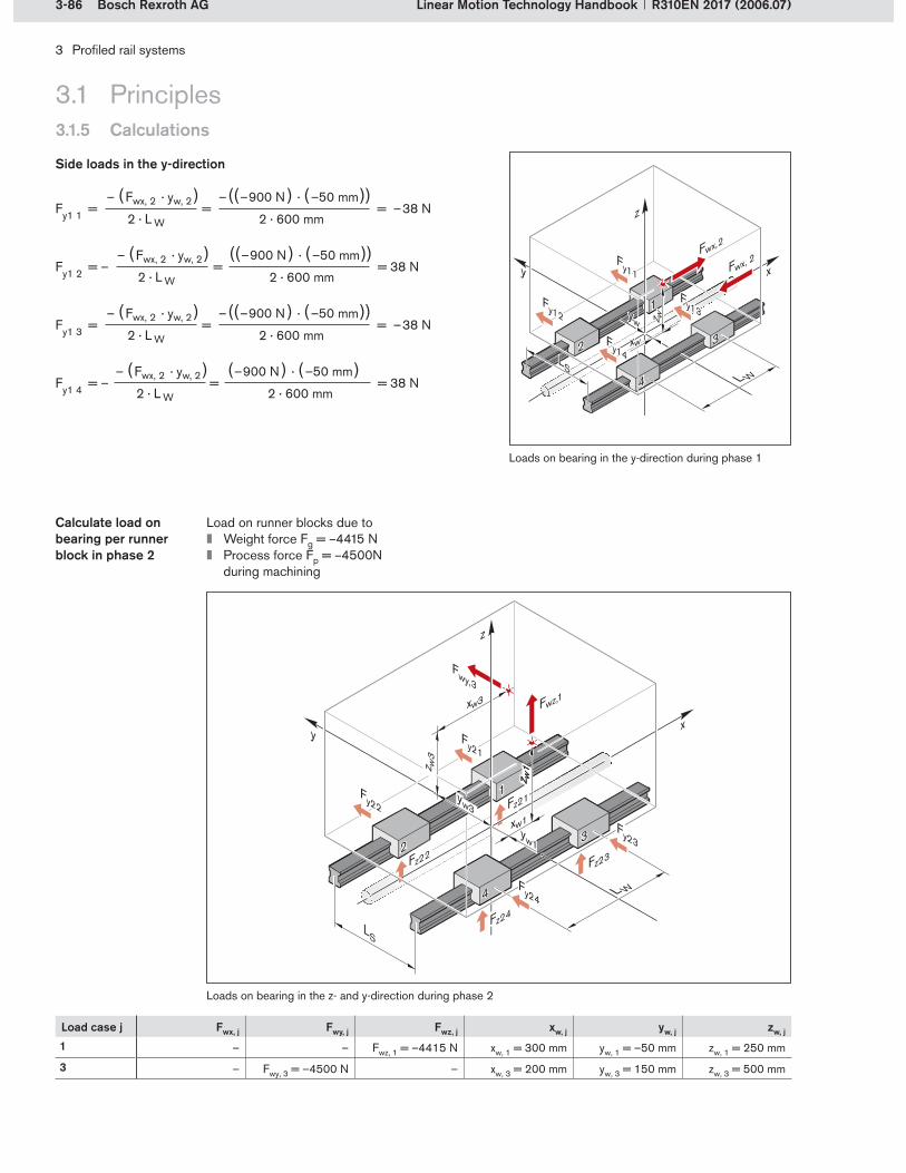
3-86 Bosch Rexroth AG
Fy1 1 = = = –38 N – (Fwx, 2 · yw, 2 ) –((–900 N ) · (–50 mm))
2 · L W 2 · 600 mm
Fy1 2 = – = = 38 N – (Fwx, 2 · yw, 2 ) ((–900 N ) · (–50 mm))
2 · L W 2 · 600 mm
Fy1 3 = = = –38 N – (Fwx, 2 · yw, 2 ) –((–900 N ) · (–50 mm))
2 · L W 2 · 600 mm
Fy1 4 = – = = 38 N – (Fwx, 2 · yw, 2 ) (–900 N ) · (–50 mm)
2 · L W 2 · 600 mm
xy
z
z w
xw
yw
LS
1
2
4
3
Fwx, 2
Fy1 1
Fy1 4
Fy1 3Fy1 2
L W
Fwx, 2
Fz2 4
Fz2 3
Fz2 1
Fz2 2
y x
L W
LS
1
2
4
3
z w3
xw3
yw3
z w1
z w1
xw1yw1
Fy2 1
Fy2 4
Fy2 3
Fy2 2
Fwz,1
Fwy, 3
z
3 Profiled rail systems
Linear Motion Technology Handbook R310EN 2017 (2006.07)
Load on runner blocks due toWeight force Fg = –4415 NProcess force Fp = –4500N during machining
Calculate load on bearing per runner block in phase 2
Load case j Fwx, j Fwy, j Fwz, j xw, j yw, j zw, j
1 – – Fwz, 1 = –4415 N xw, 1 = 300 mm yw, 1 = –50 mm zw, 1 = 250 mm
3 – Fwy, 3 = –4500 N – xw, 3 = 200 mm yw, 3 = 150 mm zw, 3 = 500 mm
3.1 Principles3.1.5 Calculations
Side loads in the y-direction
Loads on bearing in the y-direction during phase 1
Loads on bearing in the z- and y-direction during phase 2

3-87Bosch Rexroth AG
Fy 2 1 = + = + = –1875 N (–4500 N ) (–4500 N ) · 200 mm
4
Fy 2 2 = – = –375 N Fwy, 3 · xw, 3
2 · L W
Fwy, 3 · xw, 3
2 · L W
Fwy, 3 · xw, 3
2 · L W
Fwy, 3
Fwy, 3 · xw, 3Fwy, 3
4
Fy 2 3 = + = –1875 NFwy, 3
4
Fy 2 4 = – = –375 NFwy, 3
4
2 · L W 4 2 · 600 mm
Fz 2 1 = + +
Fz 2 1 = + + = 538 N (–4415 N ) (–4415 N ) · (–50 mm) – ((–4500 N ) · 500 mm) (–4415 N ) · 300 mm
4
(Fwz, 1 · yw, 1) – (Fwy, 3 · zw, 3 )2 · L S
(Fwz, 1 · xw, 1)2 · L W
Fwz, 1
4
Fz 2 2 = + + = 2745 N(Fwz, 1 · yw, 1) – (Fwy, 3 · zw, 3 )
2 · L S
– (Fwz, 1 · xw, 1)2 · L W
Fwz, 1
4
Fz 2 3 = + + = –4953 N(Fwy, 3 · zw, 3) – (Fwz, 1 · yw, 1)
2 · L S
(Fwz, 1 · xw, 1)2 · L W
Fwz, 1
4
Fz 2 4 = + + = –2745 N(Fwy, 3 · zw, 3) – (Fwz, 1 · yw, 1)
2 · L S
– (Fwz, 1 · xw, 1)2 · L W
Fwz, 1
4
2 · 450 mm 2 · 600 mm
3 Profiled rail systems
Linear Motion Technology HandbookR310EN 2017 (2006.07)
3.1 Principles3.1.5 Calculations
Lift-off/down loads in the z-direction
Side loads in the y-direction

3-88 Bosch Rexroth AG
Fz 3 1 = + +
Fz 3 1 = + + = –2150 N (–4415 N ) (–4415 N ) · (–50 mm) ((–4415 N ) · 300 mm) – (900 N · 250 mm)
4
(Fwz, 1 · xw, 1) – (Fwx, 4 · zw, 4)2 · L S
Fwz, 1 · yw, 1
2 · L W
Fwz, 1
4
(Fwx, 4 · zw, 4) – (Fwz, 1 · xw, 1)2 · L S
Fwz, 1 · yw, 1
2 · L W
Fwz, 1
4
(Fwz, 1 · xw, 1) – (Fwx, 4 · zw, 4)2 · L S
–(Fwz, 1 · yw, 1)2 · L W
Fwz, 1
4
(Fwx, 4 · zw, 4) – (Fwz, 1 · xw, 1)2 · L S
–(Fwz, 1 · yw, 1)2 · L W
Fwz, 1
4
Fz 3 2 = + + = 433 N
Fz 3 3 = + + = –2640 N
Fz 3 4 = + + = –58 N
2 · 450 mm 2 · 600 mm
Fy 3 1 = = = 38 N –(Fwx, 4 · yw, 4) – (900 N · (– 50 mm))
Fy 3 2 = – = – 38 N –(Fwx, 4 · yw, 4)
Fy 3 3 = = 38 N –(Fwx, 4 · yw, 4)
2 · L W
2 · L W
Fy 3 4 = – = – 38 N –(Fwx, 4 · yw, 4)
2 · L W
2 · L W
2 · 600 mm
3 Profiled rail systems
Linear Motion Technology Handbook R310EN 2017 (2006.07)
Runner block i Phase 1 Phase 2 Phase 3
Fz 1 i Fy 1 i Fz 2 i Fy 2 i Fz 3 i Fy 3 i1 –1775 N –38 N 538 N –1875 N –2150 N 38 N
2 58 N 38 N 2745 N –375 N 433 N –38 N
3 –2265 N –38 N –4953 N –1875 N –2640 N 38 N
4 –433 N 38 N –2745 N –375 N –58 N –38 N
3.1 Principles3.1.5 Calculations
Load on runner blocks due to Weight force Fg = –4415 NAcceleration force Fa3 = 900 N during deceleration
Calculate load on bearing per runner block in phase 3
Load case j Fwx, j Fwy, j Fwz, j xw, j yw, j zw, j
1 – – Fwz, 1 = –4415 N xw, 1 = 300 mm yw, 1 = –50 mm zw, 1 = 250 mm
4 Fwx, 4 = 900 N – – xw, 4 = 300 mm yw, 4 = –50 mm zw, 4 = 250 mm
Lift-off/down loads in the z-direction
Side loads in the y-direction
Refer to illustrations for phase 1.
Intermediate results: Loads on bearing per runner block and phase

3-89Bosch Rexroth AG
Fcomb 1 1 = Fz 1 1 + Fy 1 1 = –1775 N + – 38 N = 1813 N
Fcomb 1 2 = Fz 1 2 + Fy 1 2 = 58 N + 38 N = 96 N
Fcomb 1 3 = Fz 1 3 + Fy 1 3 = –2265 N + – 38 N = 2303 N
Fcomb 1 4 = Fz 1 4 + Fy 1 4 = –433 N + 38 N = 471 N
Fcomb 2 1 = Fz 2 1 + Fy 2 1 = 538 N + –1875 N = 2413 N
Fcomb3 4 = Fz 3 4 + Fy 3 4 = –58 N + – 38 N = 96 N
. . .
3 Profiled rail systems
Linear Motion Technology HandbookR310EN 2017 (2006.07)
3.1 Principles3.1.5 Calculations
It is also possible to calculate the loads on the runner blocks individually for each load case (weight force, acceleration forces, and process force).
Note If this is done, then the calculated individual loads have to be added as appropriate for the load case combination in the respective phase. This makes the calculation clearer.
Calculate the combined equivalent load on bearing in phase 1 for runner blocks 1 to 4:
Calculate the combined equivalent load on bearing in phase 2 and phase 3 for runner blocks 1 to 4:
Runner block i Phase 1 Phase 2 Phase 3
Fcomb 1 i Fcomb 2 i Fcomb 3 i
1 1813 N 2413 N 2188 N
2 96 N 3120 N 471 N
3 2303 N 6828 N 2678 N
4 471 N 3120 N 96 N
Intermediate results: Combined equivalent loads on bearing per runner block and phase
Step 3: Calculate combined equivalent load on bearing
The combined equivalent load on the bearing is calculated using formula (3-31).

3-90 Bosch Rexroth AG
3 Profiled rail systems
Linear Motion Technology Handbook R310EN 2017 (2006.07)
Runner block i Phase 1 Phase 2 Phase 3
Feff 1 i Feff 2 i Feff 3 i
1 4219 N 4576 N 4441 N
2 3252 N 5009 N 3456 N
3 4510 N 7485 N 4737 N
4 3456 N 5009 N 3252 N
Intermediate results: Effective equivalent load on bearing per runner block and phase
3.1 Principles3.1.5 Calculations
Calculate phases 1, 2 and 3 for runner blocks 1 to 4:
The following ball rail system was selected:Size 30, runner block flanged, long, standard height (FLS)Preload class C2 (corresponds to a preload of 8% of dynamic load capacity C, Xpr = 0.08)Dynamic load capacity C = 40,000 N
Step 4: Take the preload into account
Ball runner block flanged, long, standard height (FLS)
Calculate the preload force Fpr for the runner block according to formula (3-37):
To determine whether the preload will have an effect on the service life, the lift-off force Flim must be calculated using formula (3-38):
Since the combined equivalent load on bearing is smaller than the lift-off force for all calculated runner blocks i and phases n, the preload must be taken into account in the calculations.
Fcomb n i < Flim for all loads on bearing
For the rest of the calculation procedure, the effective equivalent load on bearing must first be calculated for all runner blocks and all phases using formula (3-40).
32
32
32
32
32
Feff 1 1 = · Fpr = · 3200 N = 4219 N Fcomb 1 1
2.8 · Fpr
1813 N2.8 · 3200 N
+1+1
Feff 1 2 = · Fpr = · 3200 N = 3252 N Fcomb 1 2
2.8 · Fpr
96 N2.8 · 3200 N
+1+1
Feff 3 4 = · Fpr = · 3200 N = 3252 N Fcomb 3 4
2.8 · Fpr
96 N2.8 · 3200 N
+1+1
. . .
32
Fpr = Xpr · C = 0.08 · 40000 N = 3200 N
Flim = 2.8 · Fpr = 2.8 · 3200 N = 8960 N
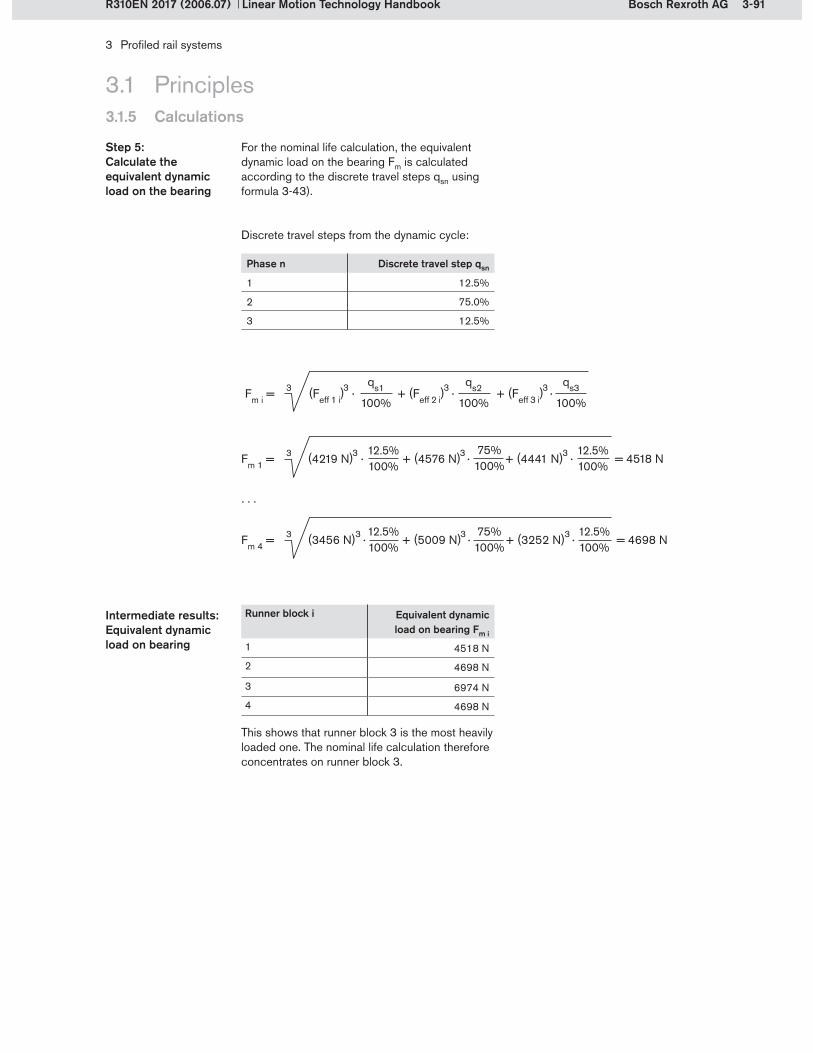
3-91Bosch Rexroth AG
3 Profiled rail systems
Linear Motion Technology HandbookR310EN 2017 (2006.07)
3.1 Principles3.1.5 Calculations
Runner block i Equivalent dynamic load on bearing Fm i
1 4518 N
2 4698 N
3 6974 N
4 4698 N
Intermediate results: Equivalent dynamic load on bearing
This shows that runner block 3 is the most heavily loaded one. The nominal life calculation therefore concentrates on runner block 3.
For the nominal life calculation, the equivalent dynamic load on the bearing Fm is calculated according to the discrete travel steps qsn using formula 3-43).
Step 5: Calculate the equivalent dynamic load on the bearing
Discrete travel steps from the dynamic cycle:
Phase n Discrete travel step qsn
1 12.5%
2 75.0%
3 12.5%
Fm i = (Feff 1 i) · + (Feff 2 i) · + (Feff 3 i) · 3 3 3 3qs1
100%
qs3
100%
qs2
100%
Fm 1 = (4219 N) · + (4576 N) · + (4441 N) · = 4518 N3 3 3 3 12.5%100%
Fm 4 = (3456 N) · + (5009 N) · + (3252 N) · = 4698 N3 3 3 3 12.5%100%
75%100%
75%100%
12.5%100%
12.5%100%
. . .
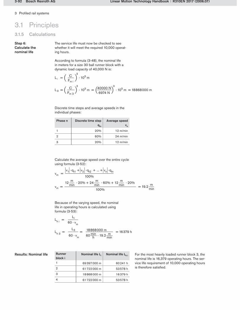
3-92 Bosch Rexroth AG
Li = · 105 m CFm i
3
L3 = · 105 m = · 105 m = 18 868 000 mCFm 3
3 40000 N6974 N
3
3 Profiled rail systems
Linear Motion Technology Handbook R310EN 2017 (2006.07)
Runner block i
Nominal life Li Nominal life Lh i
1 69 397 000 m 60 241 h
2 61 722 000 m 53 578 h
3 18 868 000 m 16 379 h
4 61 722 000 m 53 578 h
Results: Nominal life For the most heavily loaded runner block 3, the nominal life is 16,379 operating hours. The ser-vice life requirement of 10,000 operating hours is therefore satisfied.
3.1 Principles3.1.5 Calculations
Because of the varying speed, the nominal life in operating hours is calculated using formula (3-53):
Discrete time steps and average speeds in the individual phases:
Phase n Discrete time step qtn
Average speed vn
1 20% 12 m/min
2 60% 24 m/min
3 20% 12 m/min
Calculate the average speed over the entire cycle using formula (3-52):
The service life must now be checked to see whether it will meet the required 10,000 operat-ing hours.
According to formula (3-48), the nominal life in meters for a size 30 ball runner block with a dynamic load capacity of 40,000 N is:
Step 6: Calculate the nominal life
vm = = 19.212 · 20% + 24 · 60% + 12 · 20%m
minm
minm
min mmin100%
vm = v1 · qt1 + v2 · qt2 + ... + vn · qtn
100%
18 868 000 m60 · 19.2
L3
Lh i =
Lh 3 = = = 16 379 h
Li
60 · vm
60 · vm mmin
minh

3-93Bosch Rexroth AG
3 Profiled rail systems
Linear Motion Technology HandbookR310EN 2017 (2006.07)
3.1 Principles3.1.5 Calculations
According to formula (3-60), the static load safety factor for C0 = 57,800 N is:
Step 8: Calculate the static load safety factor
The maximum load Fmax occurs in phase 2 at run-ner block 3. In order to calculate the static load safety factor, the load due to the preload must also be taken into account.
Step 7: Calculate the equivalent static load on the bearing
C0Fmax
S0 =
57800 N7485 N
S0 = = 7.72

3-94 Bosch Rexroth AG
3 Profiled rail systems
Linear Motion Technology Handbook R310EN 2017 (2006.07)
3.1 Principles3.1.6 Defining the peripherals
3.1.6.1 Lubrication
An extensive range of standard parts, special add-ons and accessories is available for profiled rail systems, allowing them to be adapted to each specific application. This offer includes recom-mendations for designing the lubrication system and lubrication intervals, as well as accessories to simplify installation and maintenance of the system. There are special seals and seal kits to ensure consistently good performance in environ-mental conditions which might otherwise shorten
the life of the equipment. For humid environments, profiled rail systems can be supplied in special corrosion-resistant versions. In addition to their main purpose, the guides can also be equipped with items such as clamping and braking units, drive units, and measuring systems to extend their range of functionalities.
Rexroth offers the following solutions for enhanc-ing profiled rail guides:
Solutions Section
Lubrication 3.1.6.1
Sealing 3.1.6.2
Corrosion protection 3.1.6.3
Additional functions Clamping and braking units 3.1.6.4
Rack and pinion drives 3.1.6.4
Integrated measuring system 3.7
Note:Not all solutions are available for all types and sizes of profiled rail systems. The choice of peripherals should be considered as early as
the product selection stage. The availability of parts/versions and the relevant details can be found in the respective product catalogs.
When selecting the lubricant, the following factors must be considered:
LoadsSpeedStroke lengthTemperatureHumidityExposure to metalworking fluids Dirt/shavings
Operating conditionsOperating conditions
If linear guides are to be used in extreme operat-ing conditions, e.g. with high exposure to metal-working fluids, this must be taken into account when specifying the lubricant and the lubricant quantities. Metalworking fluids that have worked their way into a runner block can wash out the lubricant. This can be avoided by shortening the lubrication cycles.

3-95Bosch Rexroth AG
3 Profiled rail systems
Linear Motion Technology HandbookR310EN 2017 (2006.07)
3.1 Principles3.1.6 Defining the peripherals
If oil lubricants are used, the mounting orienta-tion will affect the distribution of the lubricant within the system. The number and location of the lube ports and the lubricant quantities must be specified as appropriate for the chosen mounting orientation. Details can be found in the Rexroth product catalogs.
Mounting orientationMounting orientation
Front lube units are fastened to the end faces of the runner block. They supply the rolling contact points and the seals with lubricant. Specially designed lube distribution ducts ensure that the lubricant is applied where it is needed: directly to the raceways and to the guide rail surface. This prolongs the relubrication intervals. The run-ner block should be pre-lubricated with grease. The front lube units are filled with oil. Under normal loads, they allow travel distances of up to 10,000 km without relubrication. The maximum operating temperature for front lube units is 60°C.
Front lube unitsFront lube units
The required lubrication intervals vary according to the conditions of use and the lubricant used. Lubrication intervals also depend on the loads ap-plied. Details can be found in the Rexroth product catalogs.
Lubrication intervalsLubrication intervals
Front lube unit for ball rail systems
Horizontal1 lube port atat either of the two end caps
Mounting orientation I Mounting orientation IIII
Horizontal, top-downSame port
Vertical to inclined horizontal1 lube port at top end cap
0° to max. ±90°
Information on mounting orientations and lube ports for normal-stroke applications (Examples taken from the roller rail systems product catalog; full details are given in the catalog)
Mounting orientation IIIIIIWall mounting1 lube port atat either of the two end caps
0° to max. ±90°

3-96 Bosch Rexroth AG
1
2
3 Profiled rail systems
Linear Motion Technology Handbook R310EN 2017 (2006.07)
3.1 Principles3.1.6 Defining the peripheralsDefining the peripherals
3.1.6.2 Sealing
The rolling elements and the raceways in the runner block must be protected from foreign par-ticles. Dirt or shavings can considerably shorten the life of the guide. Rexroth offers a broad range
of accessories in addition to the standard sealing options. Users can therefore put together the sealing system that best suits their needs.
Wiper seals (1) are seals integrated in the end caps. They are a standard feature in all runner blocks. Wiper seals come in different types: standard (universal) seals, low-friction seals, and reinforced (heavy-duty) seals.
Universal seals are the standard option for Rexroth runner blocks. Designed for applications in normal operating environments, they offer good sealing action and low resistance to movement.
Low-friction seals are the solution for applications requiring especially smooth running in environ-ments with little or no contamination, where sealing action is of secondary importance.
Reinforced seals were designed for operation in extreme environmental conditions. With their excellent sealing action, they provide highly effective protection.
Wiper sealsWiper seals
Integrated wiper seals in a ball runner block
Most of the profiled rail systems come standard with two or four side seals (2), providing lateral protection (perpendicular to the direction of travel) for the runner block internals.
Side seals Side seals
Version Seal types Degree of contamination
Integrated seals
Low-friction seals
Standard (universal) seals
Reinforced seals
Additional external seals
End seals(standard feature in roller rail systems)
Viton seals
Seal kit
Bellows
Integrated side seals in a ball runner block

3-97Bosch Rexroth AG
12
3
3 Profiled rail systems
Linear Motion Technology HandbookR310EN 2017 (2006.07)
3.1 Principles3.1.6 Defining the peripheralsDefining the peripherals
External end seals provide effective protection for the runner block, preventing dirt or liquids from working their way in. End seals are attached to the end face of the runner block. Depending on the type of profiled rail system, these seals may be of one-piece or two-piece design. They are standard accessories in roller rail systems.
End sealsEnd seals
Two-piece end seal
Viton seals are an additional option for external sealing. They offer even better sealing action than the end seals. However, the Viton material causes significantly higher friction. Viton seals are chemically resistant and can withstand high temperatures.
Viton sealsViton seals
Viton seal
Metal scrapers provide added protection against coarse particles. Made from stainless spring steel, they are designed to ensure effective removal of shavings and coarse contamination.
Metal scrapersMetal scrapers
Metal scraper
The seal kit is intended for applications involving a combination of coarse and fine dirt and exposure to fluids. It consists of a metal scraper (1), a rein-forcing plate (2) and a two-piece end seal (3).
Seal kitSeal kit
Seal kit
Bellows come in a variety of designs. They can be delivered with or without a lubrication plate. Heat-resistant bellows are also available. These are metallized on one side, making them resis-tant to individual sparks, welding splatter or hot shavings. They are designed for an operating temperature of 100°C, but can withstand brief temperature peaks of up to 200°C.
BellowsBellows
Bellows

3-98 Bosch Rexroth AG
3 Profiled rail systems
Linear Motion Technology Handbook R310EN 2017 (2006.07)
3.1 Principles3.1.6 Defining the peripheralsDefining the peripherals
3.1.6.3 Corrosion protection
Corrosion protection type Description
Aluminum Runner block made from aluminum
Resist NR Runner block made from corrosion-resistant steel
Resist NR II Runner block and guide rail made from corrosion-resistant steel
Resist CR Runner block and guide rail made from hard chrome plated steel
In this version, the runner block body is made of aluminum. The runner blocks have the same dynamic load capacity (100% C) as the standard steel version, but their load-bearing capability is
AluminumAluminum reduced due to the lower strength of aluminum. Rexroth therefore indicates the maximum per-missible load Fmax for these designs. Aluminum runner blocks offer weight savings up to 60%.
The runner block body is made from corrosion- resistant steel. All other steel parts are identical to those used in standard runner blocks. This design
Resist NRResist NR provides high corrosion resistance with the same dynamic and static load capacities (100% C and 100% C0) as the standard version.
In this version, all steel parts are made from corrosion-resistant steel, thus offering especially good protection against corrosion. The disadvan-tage of this design is that the load capacities are reduced (65% C) relative to the standard version because the runner block and guide rail race-ways and the rolling elements are not made from anti-friction bearing steel. Profiled rail systems in Resist NR II are specifically intended for use in applications involving aqueous media, very dilute acids, alkalis or salt solutions. They are particu-
Resist NR IIResist NR II larly suitable for environments with a relative humidity of over 70% and temperatures above 30°C, such as cleaning lines, surface treatment and pickling lines, steam degreasing equipment, and refrigeration systems. Since they have built-in corrosion protection, they are also ideal for use in cleanrooms and under vacuum. Other application areas include printed circuit board assembly, and the pharmaceuticals and food industries.
In this version, both the runner block body and the guide rail are hard chrome plated with a matt silver finish. Their corrosion resistance is cor-respondingly high. Resist CR rail guides offer the same dynamic and static load capacities (100% C and 100% C0) as the standard versions.
Resist CRResist CR The thickness of the hard chrome layer on the runner blocks and guide rails increases the out-side dimensions, resulting in different tolerances for the accuracy classes.
The corrosion protection options for the profiled rail systems range are listed below.
The product catalogs indicate which type of cor-rosion protection is available for each particular guide.

3-99Bosch Rexroth AG
3 Profiled rail systems
Linear Motion Technology HandbookR310EN 2017 (2006.07)
3.1 Principles3.1.6 Defining the peripheralsDefining the peripherals
3.1.6.4 Additional functions
Among its range of accessories, Rexroth also offers clamping and braking units. The clamping units serve to prevent linear guides from moving when they are at rest. The braking units were de-signed to bring moving linear guides to a stand-still and keep them stationary during rest phases. These elements have no guidance function.
Note:The braking units are not safety brakes!
Clamping and braking unitsClamping and braking units
Hydraulic clamping unit on a ball rail
Pneumatic clamping and braking unit on a roller rail
Clamping and braking units are available in the following versions:
Hydraulic clamping unitsPneumatic clamping unitsElectrical clamping unitsHydraulic clamping and braking units Pneumatic clamping and braking units Manual clamping units
Manual clamping unit on a roller rail
Pneumatic clamping unit on a ball rail

3-100 Bosch Rexroth AG
1
3
2 4
56
2
3 Profiled rail systems
Linear Motion Technology Handbook R310EN 2017 (2006.07)
3.1 Principles3.1.6 Defining the peripheralsDefining the peripherals
Gear rackPinion (various gear ratios possible)Shrink-fit disk
1�2�3�
Gear reducerCouplingMotor
4�5�6�
The gear rack can be lined up with the rail and bolted directly with it to the machine bed. This significantly reduces the mounting effort. Rack and pinion drives must be adequately lubricated. Permanent lubrication is therefore recommended, preferably by means of a felt wheel connected to a central lubrication system.
Advantages of rack and pinion drives:Long guideway lengthsHigh travel speedsIn multiple-carriage applications, each axis can be moved separatelyReduced mass in Z-axis, by designing applications with traveling rails (stationary motor and runner block, traveling rail and gear rack)High rigidity, especially over long strokes
Gear racks and pinions are space-saving solu-tions for driving linear motion guides. To ensure long life, Rexroth uses proven high grade steel materials with inductively hardened toothing for these components. In addition to the purely mechanical elements, all attachments such as gear reducers, motors and controllers are also available. The helical toothing allows high forces to be transmitted within a small space and with low noise generation.
Rack and pinion drives Rack and pinion drives
Ball rail system with rack and pinion drive
Rack and pinion drive components
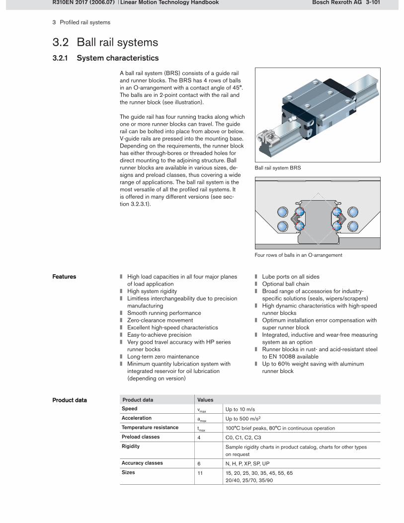
3-101Bosch Rexroth AG
3 Profiled rail systems
Linear Motion Technology HandbookR310EN 2017 (2006.07)
3.2 Ball rail systems3.2.1 System characteristics
Ball rail system BRS
A ball rail system (BRS) consists of a guide rail and runner blocks. The BRS has 4 rows of balls in an O-arrangement with a contact angle of 45°. The balls are in 2-point contact with the rail and the runner block (see illustration).
The guide rail has four running tracks along which one or more runner blocks can travel. The guide rail can be bolted into place from above or below. V-guide rails are pressed into the mounting base. Depending on the requirements, the runner block has either through-bores or threaded holes for direct mounting to the adjoining structure. Ball runner blocks are available in various sizes, de-signs and preload classes, thus covering a wide range of applications. The ball rail system is the most versatile of all the profiled rail systems. It is offered in many different versions (see sec-tion 3.2.3.1).
High load capacities in all four major planes of load applicationHigh system rigidityLimitless interchangeability due to precision manufacturingSmooth running performanceZero-clearance movementExcellent high-speed characteristicsEasy-to-achieve precisionVery good travel accuracy with HP series runner bocksLong-term zero maintenance Minimum quantity lubrication system with integrated reservoir for oil lubrication (depending on version)
FeaturesFeatures Lube ports on all sidesOptional ball chainBroad range of accessories for industry- specific solutions (seals, wipers/scrapers)High dynamic characteristics with high-speed runner blocksOptimum installation error compensation with super runner blockIntegrated, inductive and wear-free measuring system as an optionRunner blocks in rust- and acid-resistant steel to EN 10088 available Up to 60% weight saving with aluminum runner block
Product data Values
Speed vmax Up to 10 m/s
Acceleration amax Up to 500 m/s2
Temperature resistance tmax 100°C brief peaks, 80°C in continuous operation
Preload classes 4 C0, C1, C2, C3
Rigidity Sample rigidity charts in product catalog, charts for other types on request
Accuracy classes 6 N, H, P, XP, SP, UP
Sizes 11 15, 20, 25, 30, 35, 45, 55, 6520/40, 25/70, 35/90
Product dataProduct data
Four rows of balls in an O-arrangement

3-102 Bosch Rexroth AG
1
34
5
6
9
7
11
12 10
2
8
3 Profiled rail systems
Linear Motion Technology Handbook R310EN 2017 (2006.07)
3.2 Ball rail systems3.2.2 Structural design
Ball runner blocks are pre-lubricated before shipment. The customer is free to decide which lubricant to use in his application. Either grease or oil lubrication is possible. Corrosion-protected versions are available in Resist CR, Resist NR and Resist NR II.
Runner blocks, general descriptionRunner blocks, general description
For additional sealing of the runner block there are end seals, Viton seals, metal scrapers, seal kits and bellows.
Lube port (lube nipple)Threaded plateSealing plate (wiper seal)Ball guide (part of end cap)Recirculation plate (part of end cap)Lubrication insertRunner block bodyEnd capBalls (rolling elements)Ball chain (optional)Side sealGuide rail
1�2�3�4�5�6�7�8�9�10�11�12�
Structural design as implemented in a latest-generation ball rail system
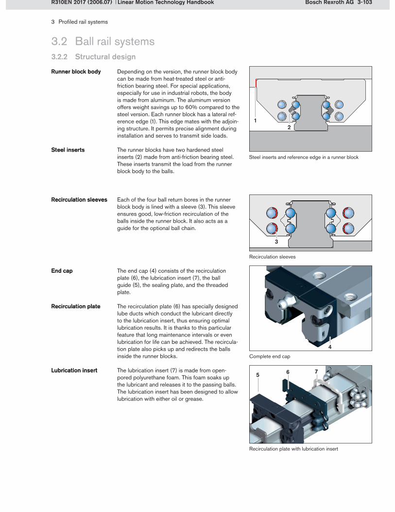
3-103Bosch Rexroth AG
12
3
4
5 6 7
3 Profiled rail systems
Linear Motion Technology HandbookR310EN 2017 (2006.07)
3.2 Ball rail systems3.2.2 Structural design
Complete end cap
Each of the four ball return bores in the runner block body is lined with a sleeve (3). This sleeve ensures good, low-friction recirculation of the balls inside the runner block. It also acts as a guide for the optional ball chain.
Recirculation sleevesRecirculation sleeves
The end cap (4) consists of the recirculation plate (6), the lubrication insert (7), the ball guide (5), the sealing plate, and the threaded plate.
End capEnd cap
The recirculation plate (6) has specially designed lube ducts which conduct the lubricant directly to the lubrication insert, thus ensuring optimal lubrication results. It is thanks to this particular feature that long maintenance intervals or even lubrication for life can be achieved. The recircula-tion plate also picks up and redirects the balls inside the runner blocks.
The lubrication insert (7) is made from open-pored polyurethane foam. This foam soaks up the lubricant and releases it to the passing balls. The lubrication insert has been designed to allow lubrication with either oil or grease.
Recirculation plateRecirculation plate
Lubrication insertLubrication insert
Recirculation plate with lubrication insert
Depending on the version, the runner block body can be made from heat-treated steel or anti- friction bearing steel. For special applications, especially for use in industrial robots, the body is made from aluminum. The aluminum version offers weight savings up to 60% compared to the steel version. Each runner block has a lateral ref-erence edge (1). This edge mates with the adjoin-ing structure. It permits precise alignment during installation and serves to transmit side loads.
The runner blocks have two hardened steel inserts (2) made from anti-friction bearing steel. These inserts transmit the load from the runner block body to the balls.
Runner block bodyRunner block body
Steel insertsSteel insertsSteel inserts and reference edge in a runner block
Recirculation sleeves

3-104 Bosch Rexroth AG
3
1 2
3 Profiled rail systems
Linear Motion Technology Handbook R310EN 2017 (2006.07)
The rolling elements are balls. Normally, these are made from anti-friction bearing steel, grade 100Cr6. Stainless steel balls are used for runner blocks that will be operating in extremely hostile environments requiring corrosion-resistant ele-ments. High-speed runner blocks have special ceramic balls. Because of their lightweight design, these balls deliver excellent dynamic performance. Ceramic balls are also good elec- trical insulators.
BallsBalls
Ceramic balls for high-speed runner blocks
3.2 Ball rail systems3.2.2 Structural design
The ball guide is fixed in place by the recirculation plate. The balls are redirected in the space be-tween these two parts. The ball guide also serves to retain the balls in the load-bearing raceway of the runner block when it is not mounted on the rail.
The ball guide also contains lube ports. The lube nipples or fittings of a central lubrication system can be inserted into these lube ports. The ports are located on the end face and at both sides. This allows lubrication from any of three direc-tions without the need for an adapter. Lubrication from the top is also possible, by opening a pre-drilled hole. The hole can be punched open using a heated, pointed metal tool to allow lubrication through the machine table. An O-ring seals the interface to the machine table. High-profile runner blocks require an adapter to compensate for the height difference between the end cap and the runner block body.
Ball guideBall guide
Lube portsLube ports
The sealing plate (2) on the end face protects internal runner block components from dirt par-ticles, shavings and liquids. It also prevents the lubricant from being dragged out. Optimized sealing lip geometry results in minimal friction. Sealing plates are available with a standard seal, low-friction seal, or a reinforced seal.
Lateral sealing strips provide additional protec-tion, keeping dirt and shavings out of the load-bearing zones. Each runner block has four of these side seals (3)..
Sealing plateSealing plate
Side sealsSide seals
Lube ports in the end cap
Sealing plate and threaded plate
The threaded plate (1) has two functions: it ac-commodates lube nipples and protects the end cap assembly. It is made from stainless steel.
Threaded plateThreaded plate
Integrated side seals in a ball runner block
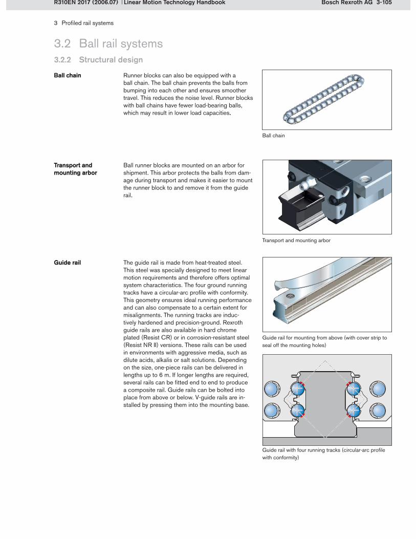
3-105Bosch Rexroth AG
3 Profiled rail systems
Linear Motion Technology HandbookR310EN 2017 (2006.07)
3.2 Ball rail systems3.2.2 Structural design
Runner blocks can also be equipped with a ball chain. The ball chain prevents the balls from bumping into each other and ensures smoother travel. This reduces the noise level. Runner blocks with ball chains have fewer load-bearing balls, which may result in lower load capacities..
Ball chainBall chain
Ball runner blocks are mounted on an arbor for shipment. This arbor protects the balls from dam-age during transport and makes it easier to mount the runner block to and remove it from the guide rail..
Transport and mounting arborTransport and mounting arbor
Ball chain
Transport and mounting arbor
The guide rail is made from heat-treated steel. This steel was specially designed to meet linear motion requirements and therefore offers optimal system characteristics. The four ground running tracks have a circular-arc profile with conformity. This geometry ensures ideal running performance and can also compensate to a certain extent for misalignments. The running tracks are induc-tively hardened and precision-ground. Rexroth guide rails are also available in hard chrome plated (Resist CR) or in corrosion-resistant steel (Resist NR II) versions. These rails can be used in environments with aggressive media, such as dilute acids, alkalis or salt solutions. Depending on the size, one-piece rails can be delivered in lengths up to 6 m. If longer lengths are required, several rails can be fitted end to end to produce a composite rail. Guide rails can be bolted into place from above or below. V-guide rails are in-stalled by pressing them into the mounting base.
Guide railGuide rail
Guide rail for mounting from above (with cover strip to seal off the mounting holes)
Guide rail with four running tracks (circular-arc profile with conformity)

3-106 Bosch Rexroth AG
3 Profiled rail systems
Linear Motion Technology Handbook R310EN 2017 (2006.07)
3.2 Ball rail systems3.2.3 Product selection guide
Ball rail systems are used in a wide variety of industries and applications. Typical examples include:
Industry sector Applications
Metal-cutting machine tools Machining centersLathes and turning machinesDrilling machinesMilling machinesGrinding machines
Nibbling machinesPlaning machinesElectrical discharge machinesLaser/light/photo beam machine tools
Assembly/handling technology and industrial robots
Assembly equipmentAssembly robots
Multi-purpose industrial robotsGripping and clamping equipment
Woodworking and wood processing machines
Belt sawsCircular sawsPlaning machinesDrilling machines
Mortising machinesSanding machinesSlitters
Rubber and plastics processing machinery
Calendering machinesRolling millsExtruders
Blow molding machinesInjection molding machines
Food industry Filling machinesMolding machines
Confectionary technology
Printing and paper industry Paper and pulp machinesCutters for paper and cellulose
Packaging machinesWinders/rewindersPrinting machinesPaper converting machines
Automotive industry Car production lines Welding systems
Forming and stamping machine tools
Bending machinesStraightening/leveling machines
PressesWire bending machines
3.2.3.1 Versions
3.2.3.2 Application areas
Runner blocks with or without ball chainSuper runner blocks with self-alignment capability Aluminum runner blockHigh-speed runner blocks High-precision ball runner blocksCorrosion-resistant ball guide rails
Rexroth offers many different designs and versions to meet the needs of a broad range of applications:
Runner block formats
Width F S B
Length N N L K K N N N L L K K N
Height S N S S N S N H S H S N N
Code FNS FNN FLS FKS FKN SNS SNN SNH SLS SLH SKS SKN BNN

3-107Bosch Rexroth AG
3 Profiled rail systems
Linear Motion Technology HandbookR310EN 2017 (2006.07)
3.3 Miniature ball rail systems3.3.1 System characteristics
There is a growing demand for miniaturization. This is driven by various factors:
Complex parts are being redesigned with ever smaller dimensionsNeed for compact and highly precise equip-ment to perform pick-and-place operations within a small spaceLower masses of moved parts mean lower moment loads and mass moments of inertiaSmaller installation spaces to make room for new technologies
Rexroth has responded to this trend by develop-ing miniature ball rail systems. These systems have two rows of balls with a contact angle of 45°. The rolling elements have 4-point contact.
Extremely compact design with high load- bearing capabilitySame load capacities in all four major planes of load applicationHigh load capacities in all load directions, including moments about all axes, due to the use of largest possible ball sizesSmooth running thanks to optimized ball recirculation and guidanceLow-friction seals ensure low friction despite 4-point contactLimitless interchangeability due to precision manufacturingZero-maintenance for a travel life of at least 5,000 km at:
F < 10% C vm = 0.65 m/s Stroke = 90 mm Low-friction seals
Cleanroom certification (class 10 to US Fed. Std. 209E)High permissible travel speed and accelerationEasy mounting due to ball retention
FeaturesFeatures
Miniature ball rail system
Product data Values
Speed vmax Up to 5 m/s
Acceleration amax Up to 250 m/s2
Temperature resistance tmax 100°C brief peaks, 80°C in continuous operation
Preload classes 2 Clearance, preload
Rigidity Rigidity charts for lift-off and down loads in product catalog
Accuracy classes 3 N, H, P
Sizes 8 7, 9, 12, 15, 209B, 12B, 15B
Product dataProduct data
2 rows of balls with 4-point contact
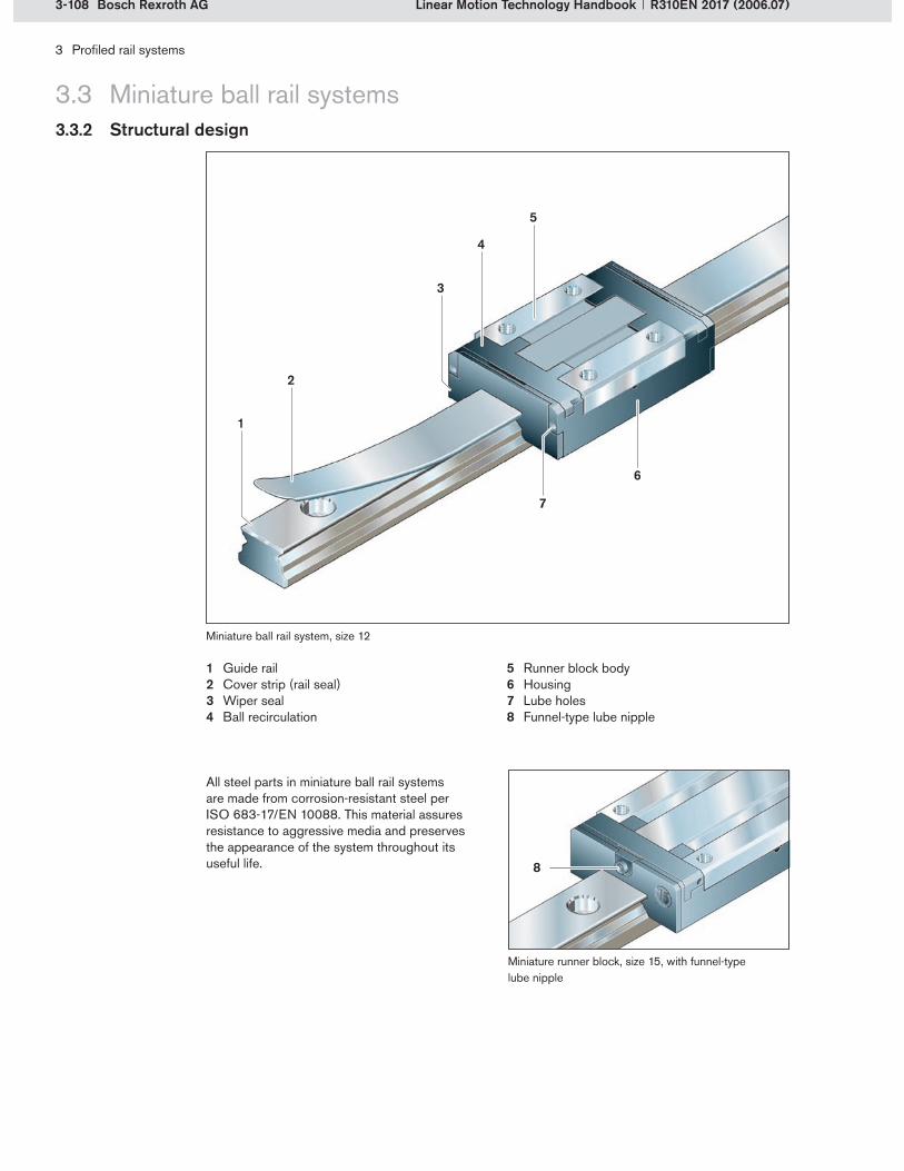
3-108 Bosch Rexroth AG
6
1
2
7
4
5
3
8
3 Profiled rail systems
Linear Motion Technology Handbook R310EN 2017 (2006.07)
3.3 Miniature ball rail systems3.3.2 Structural design
Guide railCover strip (rail seal)Wiper sealBall recirculation
1�2�3�4�
Runner block bodyHousingLube holesFunnel-type lube nipple
5�6�7�8�
All steel parts in miniature ball rail systems are made from corrosion-resistant steel per ISO 683-17/EN 10088. This material assures resistance to aggressive media and preserves the appearance of the system throughout its useful life.
Miniature ball rail system, size 12
Miniature runner block, size 15, with funnel-type lube nipple

3-109Bosch Rexroth AG
2
4
1
1
3
3 Profiled rail systems
Linear Motion Technology HandbookR310EN 2017 (2006.07)
3.3 Miniature ball rail systems3.3.2 Structural design
The standard versions of these runner blocks have dimensions per DIN 645-2. Wide and long versions are also available. The runner blocks can be ordered with or without basic lubrica-tion, thus allowing lubrication with grease or oil, as required. Lubrication holes are provided for in-service lubrication of the runner blocks. From size 15 and up, miniature ball rail systems have an additional lube hole at the side, as well as the lube nipple on the end face.
Runner blocks, general descriptionRunner blocks, general description
Lube holes or lube nipples Lube holes or lube nipples
The runner block body (1) has four threads at the top for fastening to the adjoining structure. The steel part is hardened throughout and is also corrosion-resistant. Reference edges on both sides facilitate mounting to the surrounding machine structures.
Runner block bodyRunner block body
The runner block body (1) has a ball recirculation assembly (2) at each end. Each row of balls recir-culates outward through a lateral return bore. The ball recirculation assembly consists of a recircula-tion piece and a sealing plate which contains the lube ducts.
Ball recirculationBall recirculation
The recirculating balls are protected and guided by a channel formed by the housing (3) and the body. The housing encloses the body and pro-vides a mounting surface for all attachments.
A retaining wire (4) reliably retains the balls inside the load-bearing raceways of the runner block. This simplifies handling during mounting and removal of the runner block and thus reduces the installation time.
HousingHousing
Retaining wireRetaining wire
Runner block body
Ball recirculation assembly with housing and retaining wire
Lube holes (example: size 12)

3-110 Bosch Rexroth AG
1
2
3 Profiled rail systems
Linear Motion Technology Handbook R310EN 2017 (2006.07)
3.3 Miniature ball rail systems3.3.2 Structural design
The balls used in the runner block are made from corrosion-resistant and specially hardened steel. This wear-resistant material is ideal for use in miniature ball rail systems.
BallsBalls
Miniature runner blocks come standard with low-friction wiper seals (1). It is, however, also possible to install a standard seal with excellent wiping properties.
Wiper sealsWiper seals
All miniature runner blocks are delivered mounted on an arbor. This arbor protects the balls from damage during transport and makes it easier to install and remove the runner block.
Transport and mounting arborTransport and mounting arbor
Standard miniature guide rails are fully hardened and have through-holes for mounting from above. Mounting hole cover strips are available for size 9 and larger rails. Guide rails can also be supplied in versions for mounting from below. Rexroth offers these guide rails in one-piece lengths up to 2 m. Larger rail lengths are made up of matching rail sections mounted end to end.
Guide railGuide rail
The cover strip is made from stainless steel and simply clips on to the rail. It prevents dirt from col-lecting in the rail’s mounting holes and interacts with the seals to provide optimal sealing action.
Cover stripCover strip
Wiper seal
Guide rail for mounting from above (with cover strip to seal off the mounting holes)
Side seals (example: size 15)
Miniature runner block, size 12, on mounting arbor
Some runner block sizes can be fitted with a standard seal and a two-piece side seal (2) on the underside of the runner block, resulting in a fully sealed design.
Side sealsSide seals

3-111Bosch Rexroth AG
3 Profiled rail systems
Linear Motion Technology HandbookR310EN 2017 (2006.07)
3.3 Miniature ball rail systems3.3.3 Product selection guide
Industry sector Applications
Textile technology Spinning machinesYarn doubling machinesAuxiliary equipment
Weaving machinesTextile finishing machinesKnitting and hosiery machines
Rubber and plastics processing machinery
Demolders for plastics processing machinesExtruders
Blow molding machinesInjection molding machines
Assembly/handling technology and industrial robots
Assembly equipmentAssembly robotsMulti-purpose industrial robots
Gripping and clamping equipmentSmall parts handlingIndustrial robots
Medical technology MicroscopesDiagnostic equipment
Analytical instruments
Electrical/electronics industry MicroelectronicsSemiconductor manufacturing
Computer peripheralsAutomated PCB assembly systems
Food and packaging industries Cleanroom applicationsLabeling machines
Filling machinesBoxing machines
Printing and paper industry Cutters for paper and cellulose Paper converting machinesBookbinding machines
Precision machine tools Measuring machines Small tools
Examples of the broad range of applications for miniature ball rail systems:
Runner block formats
Width S B
Length N L N
Height S S S
Code SNS SLS BNS
3.3.3.1 Versions
3.3.3.2 Application areas

3-112 Bosch Rexroth AG
3 Profiled rail systems
Linear Motion Technology Handbook R310EN 2017 (2006.07)
3.4 eLINE ball rail systems3.4.1 System characteristics
Rexroth’s eLINE range of ball rail systems was developed especially for light machinery and for handling and positioning movements where the main emphasis is on economy and durability. eLINE guides offer an excellent price-performance ratio.
The eLINE ball rail system has two rows of balls with 4-point contact. The balls have a contact angle of 45°. The runner block body and the guide rail profile are made of aluminum. The load-bearing capability is achieved by means of hardened steel inserts in the rail and the runner block.
eLINE ball rail system
Product data Values
Speed vmax Up to 2 m/s
Acceleration amax Up to 30 m/s2
Temperature resistance tmax 60°C in continuous operation
Preload classes 2 C0, C1
Rigidity Rigidity charts on request
Accuracy classes 2 E, N
Sizes 3 15, 20, 25
Product dataProduct data
Low weightCompact designSame load capacities in all four major planes of load applicationLow accuracy requirements on the mating surfaces in the adjoining structureSignificantly better corrosion resistance compared with the steel versionsLimitless interchangeability due to precision manufacturingLarge balls make this profiled rail system insensitive to dirtOptional front lube unit with sealing functionAvailable in the most common DIN sizes and formats
FeaturesFeatures
2 rows of balls with 4-point contact

3-113Bosch Rexroth AG
2
3
4
5
7
6
1
3 Profiled rail systems
Linear Motion Technology HandbookR310EN 2017 (2006.07)
3.4 eLINE ball rail systems3.4.2 Structural design
Seal unit (wiper seal)End capRunner block body with integrated steel insert
1�2�3�
Row of ballsHousingGuide rail bodySteel insert in guide rail
4�5�6�7�
Components of the eLINE ball rail system

3-114 Bosch Rexroth AG
5
2
3
3
4
1
3 Profiled rail systems
Linear Motion Technology Handbook R310EN 2017 (2006.07)
3.4 eLINE ball rail systems3.4.2 Structural design
The runner blocks are available in flanged and slimline designs. They are pre-lubricated in-factory, therefore provided with long-term lubrication. A front lube unit with sealing function is available as an accessory, allowing the runner blocks to be relubricated with oil when in service.
Runner blocks, general descriptionRunner blocks, general description
Steel inserts in the runner block
The runner block body (1) is made from aluminum. This considerably reduces the overall weight of the runner block. The runner blocks can be fastened from above or below (depending on the version) using four screws.
Runner block bodyRunner block body
Hardened steel inserts (2) are integrated in the runner blocks as raceways for the balls.
Steel inserts Steel inserts
The steel balls are prevented from falling out by a retaining plate. Thanks to these retaining plates the runner blocks can be easily removed from the rail, which significantly simplifies mounting and disassembly.
The balls are guided out of the load-bearing zone into the recirculation zone by two lateral housing parts (3), which also form the recirculation chan-nel in combination with the aluminum body. They protect the balls from external influences.
The end caps (4) also form part of the ball recir-culation geometry. They have clip fasteners (5) for easy fastening to the aluminum body and safe retention of the plastic internals. In addition, the end caps accommodate the seal unit or the front lube unit with sealing function.
Retaining plateRetaining plate
HousingHousing
End capsEnd capsEnd caps with clip fasteners

3-115Bosch Rexroth AG
2
1
3
4
4
3 Profiled rail systems
Linear Motion Technology HandbookR310EN 2017 (2006.07)
3.4 eLINE ball rail systems3.4.2 Structural design
Each runner block comes with two seal units (1) mounted at the end faces. These seal units can be pulled out and replaced with lube units with sealing function. Seal units are two-piece compo-nents consisting of a holder and a foam insert.
Seal unitSeal unit
The lube unit (3) allows in-service lubrication of the runner block while providing an added sealing function. These lube units are available as acces-sories.
Lube unit with sealing function Lube unit with sealing function
The runner blocks are delivered mounted on an arbor (2). This arbor prevents any loss of balls while the runner block is being transported and facilitates mounting of the runner block to the rail.
Transport and mounting arborTransport and mounting arbor
eLINE guide rails consist of a rail body and two steel inserts (4). The steel inserts are the running tracks for the balls and are therefore made from hardened steel. The rail is bolted to the mounting base from above or below. The mounting holes can then be closed with plastic plugs.
Guide railGuide rail
eLINE runner block with seal unit
Lube unit with sealing function as an accessory
eLINE guide rail (with plastic mounting hole plugs)
Steel inserts in the eLINE guide rail

3-116 Bosch Rexroth AG
3 Profiled rail systems
Linear Motion Technology Handbook R310EN 2017 (2006.07)
3.4 eLINE ball rail systems3.4.3 Product selection guide
The application areas for eLINE ball rail systems are different from those of the ball rail systems mentioned earlier. The nominal life calculation for the eLINE range has therefore been simplified. The load on the bearing Pact is calculated using a number of factors: the coefficient for the operat-ing condition kf , and the coefficients for loads due to torsional moments kt and longitudinal moments kL . The required size can be selected using the calculated load on the bearing Pact and a maxi-mum load on the bearing Pmax . The outcome of the calculation is the travel life in kilometers, according to the type of lubrication used.
3.4.3.2 Application areas
eLINE ball rail systems were designed for use in applications calling for good performance at an affordable price. Typical areas are:
Industry sector Applications
Building services technologyTradeshow and shop furnishings
Door and window technologyFurniture elementsInterior design
Assembly/handling technology and industrial robots
Assembly equipmentAssembly linesPositioning unitsManual displacement systemsGripping and clamping equipment
Special-purpose machines Jigs and fixturesLight machineryMachine enclosures
DIY Various DIY projects
If required, the exact nominal life can be cal- culated in the usual way, using the equivalent load on bearing and the load capacity (see section 3.1.5). Because of the weight-optimized design of eLINE ball rail systems, the maximum permissible forces Fmax and the maximum permis-sible torsional moments Mt max and longitudinal moments ML max must not be exceeded.
Details of the full and the simplified nominal life calculation can be found in the eLINE ball rail systems catalog.
3.4.3.3 Simplified calculations
Runner block formats
Width F S
Length N N
Height S S
Code FNS SNS
3.4.3.1 Versions

3-117Bosch Rexroth AG
3 Profiled rail systems
Linear Motion Technology HandbookR310EN 2017 (2006.07)
3.5 Roller rail systems3.5.1 System characteristics
Rexroth roller rail systems were designed especially for applications in machine tools and industrial robots. Available in various accuracy classes, these linear guides have exceptionally high load-bearing capacity and rigidity.
Roller rail systems have four roller bearing circuits in an O-arrangement. The rollers are in line-contact with the raceways at a contact angle of 45°.
Roller rail system
Product data Values
Speed vmax Up to 3 m/s
Acceleration amax Up to 50 m/s2
Temperature resistance tmax 100°C brief peaks, 80°C in continuous operation
Preload classes 4 C2, C3 (C1 on request)
Rigidity Rigidity charts showing lift-off/down/side loads for all types in product catalog
Accuracy classes 4 H, P, SP, UP
Sizes 9 25, 35, 45, 55, 65, 100, 12555/85, 65/100
Product dataProduct data
Rolling elements: rollersVery high static load capacitiesVery high dynamic load capacitiesHigh static torque capacity Very high rigidity in all major planes of load applicationVery good travel performance even under extremely high loadsUnlimited interchangeability due to precision manufacturingIntegrated all-round sealingBroad range of accessories for special sectoral solutions (seals, wipers/scrapers) Integrated, inductive and wear-free measuring system as an optionClamping and braking units available
FeaturesFeatures
Four rows of rollers in an O-arrangement
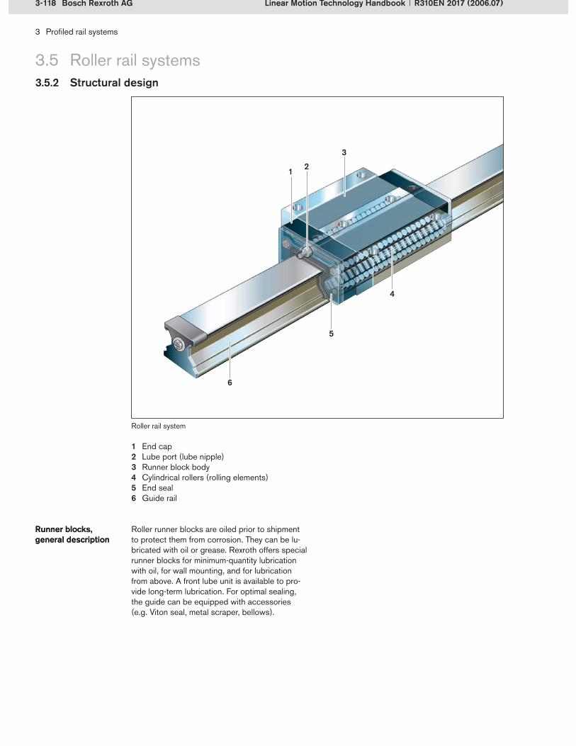
3-118 Bosch Rexroth AG
1 2
3
4
5
6
3 Profiled rail systems
Linear Motion Technology Handbook R310EN 2017 (2006.07)
3.5 Roller rail systems3.5.2 Structural design
End capLube port (lube nipple)Runner block bodyCylindrical rollers (rolling elements)End sealGuide rail
1�2�3�4�5�6�
Roller runner blocks are oiled prior to shipment to protect them from corrosion. They can be lu-bricated with oil or grease. Rexroth offers special runner blocks for minimum-quantity lubrication with oil, for wall mounting, and for lubrication from above. A front lube unit is available to pro-vide long-term lubrication. For optimal sealing, the guide can be equipped with accessories (e.g. Viton seal, metal scraper, bellows).
Runner blocks, general descriptionRunner blocks, general description
Roller rail system

3-119Bosch Rexroth AG
3
1 2
45
3 Profiled rail systems
Linear Motion Technology HandbookR310EN 2017 (2006.07)
3.5 Roller rail systems3.5.2 Structural design
Rexroth runner block bodies are available in four versions according to DIN 645-1 and in various special versions. All runner block bod- ies are made from anti-friction bearing steel. Depending on their design, same-size runner blocks may have different load capacities and rigidities.
The runner block bodies contain four raceways and recirculation bores for the rolling elements and have threaded holes for mounting to the adjoining structure.
Runner block bodyRunner block body
Runner block body
Stress distribution in a logarithmic roller profile
The rolling elements in the runner block bodies are rollers with a logarithmic profile. This profile prevents excessive stresses at the edges and helps to prolong the life of the runner block. The rollers are made from grade 100Cr6 anti-friction bearing steel.
Logarithmic rollerLogarithmic roller
The rollers are guided by recirculation pieces and a frame. To keep the friction as low as possible, all of the roller guidance parts are made from a plastic material with excellent sliding friction properties.
The recirculation piece guides the rollers from the load-bearing zone to the return zone. In the O-arrangement used by Rexroth the rolling ele-ments are recirculated cross-wise. Integrated lube ducts ensure that all raceways are reliably lubricated.
The main purpose of the frame is to provide lat-eral guidance for the rollers in the runner block load-bearing zones. The frames also retain the rollers and prevent them from dropping out during mounting and removal of the runner blocks.
Two integrated side seals per frame protect the rolling elements and the raceways from dirt.
The recirculation zone of the roller runner blocks essentially consists of return channels. As with the roller guidance parts, the return channels are made from a plastic material with good sliding properties. Lateral pockets ensure adequate lubricant transport and reduce friction.
Roller guidanceRoller guidance
Recirculation piece (roller pick-up)Recirculation piece (roller pick-up)
FrameFrame
Side sealsSide seals
Return channelReturn channel
Roller guidance and return channels
Roller load-bearing zoneRoller recirculation zoneReturn channelsSide seals (4x)Frame
1�2�3�4�5�
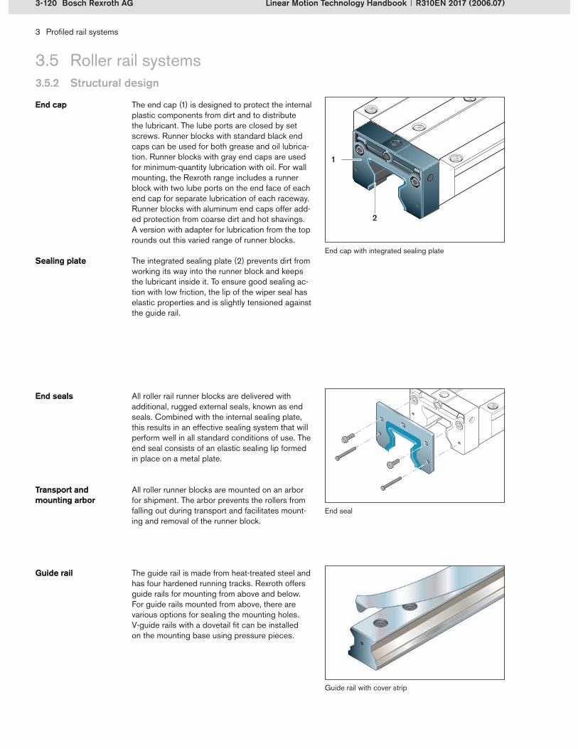
3-120 Bosch Rexroth AG
2
1
3 Profiled rail systems
Linear Motion Technology Handbook R310EN 2017 (2006.07)
3.5 Roller rail systems3.5.2 Structural design
The end cap (1) is designed to protect the internal plastic components from dirt and to distribute the lubricant. The lube ports are closed by set screws. Runner blocks with standard black end caps can be used for both grease and oil lubrica-tion. Runner blocks with gray end caps are used for minimum-quantity lubrication with oil. For wall mounting, the Rexroth range includes a runner block with two lube ports on the end face of each end cap for separate lubrication of each raceway. Runner blocks with aluminum end caps offer add-ed protection from coarse dirt and hot shavings. A version with adapter for lubrication from the top rounds out this varied range of runner blocks.
The integrated sealing plate (2) prevents dirt from working its way into the runner block and keeps the lubricant inside it. To ensure good sealing ac-tion with low friction, the lip of the wiper seal has elastic properties and is slightly tensioned against the guide rail.
End capEnd cap
Sealing plateSealing plate
All roller rail runner blocks are delivered with additional, rugged external seals, known as end seals. Combined with the internal sealing plate, this results in an effective sealing system that will perform well in all standard conditions of use. The end seal consists of an elastic sealing lip formed in place on a metal plate.
All roller runner blocks are mounted on an arbor for shipment. The arbor prevents the rollers from falling out during transport and facilitates mount-ing and removal of the runner block.
End sealsEnd seals
Transport and mounting arborTransport and mounting arbor
The guide rail is made from heat-treated steel and has four hardened running tracks. Rexroth offers guide rails for mounting from above and below. For guide rails mounted from above, there are various options for sealing the mounting holes. V-guide rails with a dovetail fit can be installed on the mounting base using pressure pieces.
Guide railGuide rail
End cap with integrated sealing plate
End seal
Guide rail with cover strip

3-121Bosch Rexroth AG
3 Profiled rail systems
Linear Motion Technology HandbookR310EN 2017 (2006.07)
3.5 Roller rail systems3.5.3 Product selection guide
Industry sector Applications
Metal-cutting machine tools Machining centersLathes and turning machinesDrilling machinesMilling machines
Grinding machinesNibbling machinesElectrical discharge machinesLaser/light/photo beam machine tools
Forming and stamping machine tools
Bending machinesStraightening/leveling machinesPresses
Wire bending machinesWire drawing machines
Rubber and plastics processing machinery
Injection molding machinesExtruders
Calendering machinesBlow molding machines
Automotive industry Car production linesWelding systems
Pressing and stamping linesPaintshop systems
Paper and printing machines Paper winders/unwindersPrinting machines
Cutters
Assembly/handling technology, industrial robots
Heavy duty equipmentCable and tape reelers
Palletizer robots
Steel industry rolling mills Roll adjustment Coilers/uncoilers
Welding technology Automatic weldersHot welding equipment
Friction welding equipment
Food and packaging industries PalletizersMolding machines
Cutters
Woodworking and wood processing machines
Heavy duty wood processing equipment
Sawing machines
Runner block formats
Width F S B
Length N L N L N
Height S S H H N
Code FNS FLS SNH SLH BNN
3.5.3.1 Versions
3.5.3.2 Application areas
Roller rail systems with Resist CRWide roller rail systemsHeavy duty roller rail systemsRunner blocks for wall mounting
Runner blocks with aluminum end capsRunner blocks for central oil lubrication systems (minimum-quantity lubrication)
Rexroth offers different designs and versions to meet the needs of a broad range of applications:

3-122 Bosch Rexroth AG
2 31
3 Profiled rail systems
Linear Motion Technology Handbook R310EN 2017 (2006.07)
3.6 Cam roller guides3.6.1 System characteristics
Rexroth cam roller guides were developed primar-ily for handling and automation applications. They differ from typical profiled rail systems because the rolling elements do not circulate between the runner blocks and the guide rails. The main components of cam roller guides are the cam rollers (1), which are mounted on ball bearings. Made from steel, the cam rollers guide the runner blocks along the running tracks (2) in the guide rail (3).
Cam roller guide
Product data Values
Speed vmax 10 m/s
Acceleration amax 50 m/s2
Higher acceleration possible, provided slip is avoided
Temperature resistance tmax 8°C
Preload classes none Adjustable via eccentric spigots/pins
Rigidity Depends on eccentric spigot/pin adjustment
Accuracy classes 1 One accuracy class, higher accuracies available on request
Sizes 5 20, 25, 32, 42, 52
Product dataProduct data
High load-bearing capability in all four major planes of load applicationHigh moment load capacity about all axes Very high permissible speedCompact dimensionsVery low weight Easy mounting Low friction Low-noise operationComplete guide unitRugged designInterchangeable elements readily availableLow demands on accuracy of the adjoining structures
FeaturesFeatures
Cam roller guide – schematic of operating principle
Higher rigidity can be achieved by adjusting the eccentric spigot/pin to increase the preload force.
Unlike all other profiled rail systems, cam roller guides have no accuracy classes. All sizes have the same accuracy values (see product catalog).

3-123Bosch Rexroth AG
12
3
5
6
78
4
3 Profiled rail systems
Linear Motion Technology HandbookR310EN 2017 (2006.07)
3.6 Cam roller guides3.6.2 Structural design
Cam roller guides are available in many different versions. They generally consist of at least one guide rail and at least one runner block with cam rollers. The structural design is illustrated below, using a standard cam roller runner block as an example. This is the most commonly used design. Further designs are shown in section 3.6.3.1.
Oil applicator/wiper unitRunner block bodyEccentric cam roller spigotCentral cam roller spigot
1�2�3�4�
Cam rollerLube port (lube nipple)Guide rail bodyPrecision steel shaft
5�6�7�8�
Components of the cam roller guide
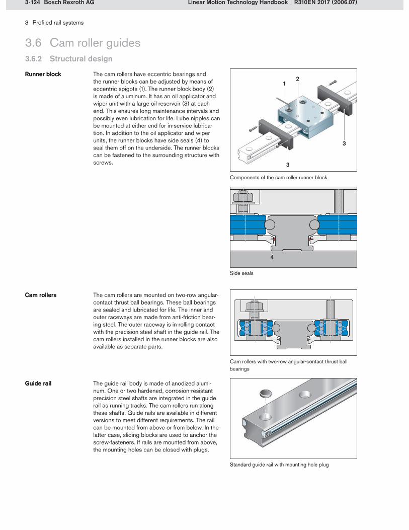
3-124 Bosch Rexroth AG
21
3
3
4
3 Profiled rail systems
Linear Motion Technology Handbook R310EN 2017 (2006.07)
3.6 Cam roller guides3.6.2 Structural design
The cam rollers have eccentric bearings and the runner blocks can be adjusted by means of eccentric spigots (1). The runner block body (2) is made of aluminum. It has an oil applicator and wiper unit with a large oil reservoir (3) at each end. This ensures long maintenance intervals and possibly even lubrication for life. Lube nipples can be mounted at either end for in-service lubrica-tion. In addition to the oil applicator and wiper units, the runner blocks have side seals (4) to seal them off on the underside. The runner blocks can be fastened to the surrounding structure with screws.
Runner blockRunner block
Components of the cam roller runner block
Side seals
Cam rollers with two-row angular-contact thrust ball bearings
The guide rail body is made of anodized alumi-num. One or two hardened, corrosion-resistant precision steel shafts are integrated in the guide rail as running tracks. The cam rollers run along these shafts. Guide rails are available in different versions to meet different requirements. The rail can be mounted from above or from below. In the latter case, sliding blocks are used to anchor the screw-fasteners. If rails are mounted from above, the mounting holes can be closed with plugs.
Guide railGuide rail
Standard guide rail with mounting hole plug
The cam rollers are mounted on two-row angular-contact thrust ball bearings. These ball bearings are sealed and lubricated for life. The inner and outer raceways are made from anti-friction bear-ing steel. The outer raceway is in rolling contact with the precision steel shaft in the guide rail. The cam rollers installed in the runner blocks are also available as separate parts.
Cam rollersCam rollers
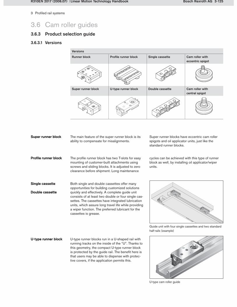
3-125Bosch Rexroth AG
3 Profiled rail systems
Linear Motion Technology HandbookR310EN 2017 (2006.07)
The main feature of the super runner block is its ability to compensate for misalignments.
Super runner blockSuper runner block
The profile runner block has two T-slots for easy mounting of customer-built attachments using screws and sliding blocks. It is adjusted to zero clearance before shipment. Long maintenance
Profile runner blockProfile runner block
3.6 Cam roller guides3.6.3 Product selection guide
Both single and double cassettes offer many opportunities for building customized solutions quickly and effectively. A complete guide unit consists of at least two double or four single cas-settes. The cassettes have integrated lubrication units, which assure long travel life while providing a wiper function. The preferred lubricant for the cassettes is grease.
Single cassetteSingle cassette
Double cassetteDouble cassette
U-type runner blocks run in a U-shaped rail with running tracks on the inside of the “U”. Thanks to this geometry, the compact U-type runner block is protected by the guide rail. The benefit here is that users may be able to dispense with protec-tive covers, if the application permits this.
U-type runner blockU-type runner block
Versions
Runner block Profile runner block Single cassette Cam roller with eccentric spigot
Super runner block U-type runner block Double cassette Cam roller with central spigot
3.6.3.1 Versions
Guide unit with four single cassettes and two standard half-rails (example)
Super runner blocks have eccentric cam roller spigots and oil applicator units, just like the standard runner blocks.
cycles can be achieved with this type of runner block as well, by installing oil applicator/wiper units.
U-type cam roller guide
3-126 Bosch Rexroth AG
3 Profiled rail systems
Linear Motion Technology Handbook R310EN 2017 (2006.07)
3.6 Cam roller guides3.6.3 Versions, application areas, different calculation procedure
The nominal life calculation for cam roller guides differs from that of other profiled rail systems. The static load capacity C0 y, z and the dynamic load capacity Cy, z are calculated using the load ratings of the integrated angular-contact thrust ball bearings instead of the rolling contact be-tween the running track and the cam roller. These load capacities result in static load moment capacities M0 x, y, z and dynamic load moment capacities Mx, y, z for calculation of the moment loads.
Cam roller guides are used in the following indus-tries, mainly in applications with low loads and high speeds. They are often installed in auxiliary equipment serving the main production machines.
Industry sector
Assembly/handing/industrial robots
Food and packaging industries
Metal-cutting machine tools
Printing and paper industry
Electrical/electronics industry
Rubber and plastics processing machinery
Machinery for building materials, ceramics and glass
Conveyor systems
Precision machine tools
Forming and stamping machine tools
3.6.3.3 Different calculation procedure
3.6.3.2 Application areas
In addition, there are load limits for effective dynamic forces Fmax y, z , static forces F0 max y, z , and for dynamic moments Mmax x, y, z and static moments M0 max x, y, z . This takes account of the strength of the rail and the runner block, the load-bearing capability of the cam rollers and of the screw connections. The load capacities and maximum permissible loads are given in the prod-uct catalog for all versions and sizes.

3-127Bosch Rexroth AG
3 Profiled rail systems
Linear Motion Technology HandbookR310EN 2017 (2006.07)
3.7 Integrated measuring system3.7.1 Position measuring systems principles
A variety of different principles can be used to measure linear travel. In order to understand the advantages and disadvantages of the different systems, certain terms have to be explained first.
There are direct and indirect position measuring systems. In direct position measuring systems, the linear displacement is measured using a scale, which must be as long as the entire travel distance. By contrast, indirect position measuring
Direct and indirect position measuring systems
systems measure linear displacement by means of changes in the angular position of the drive. The Rexroth measuring system is a direct linear measuring system.
A distinction is made between incremental and absolute systems. Incremental position measuring systems measure only changes in the distance traveled. A homing cycle has to be performed to determine the absolute position. The system that Rexroth uses is an incremental one.
Incremental and absolute position measuring systems
Incremental and absolute position measuring systems
In absolute systems the precise position is always known immediately after system start-up. No ref-erencing is required to find the zero point.
Linear measuring systems
Example: Scale
Direct
Position measuring systems
Coded
Runtime measurement (laser, ultrasonic)
Capacitative
Resistive
Inductive
Magnetic
Optical
IncrementalIncremental Absolute
Rotary measuring systems
Indirect
Incremental AbsoluteAbsolute
Example: Rotary encoder

3-128 Bosch Rexroth AG
3 Profiled rail systems
Linear Motion Technology Handbook R310EN 2017 (2006.07)
3.7 Integrated measuring system3.7.1 Position measuring system principles
Another distinguishing feature of position measur-ing systems is the design of the sensors used. It is useful to have a system which supplies electri-cal measurement signals. The measuring principle
Operating principles of position measur-ing systems
Operating principles of position measur-ing systems
This method involves travel-dependent influencing of electromagnetic inductance by reciprocal dis-placement of AC-powered coil systems and iron cores (plunger-type and yoke-type armatures).
Inductive measuring systemsInductive measuring systems
Optical beam paths can be used in combina-tion with apertures of defined sizes or graduated scales with coded or incremental, light-permeable areas or grids to generate analog signals. Using
Optical position measuring systemsOptical position measuring systems
Magnetic measuring systems are based on travel-dependent influencing of magnetic effects in suitable sensors, e.g. Hall sensors.
Magnetic position measuring systemsMagnetic position measuring systems
Position measuring systems Advantages Disadvantages
Optical systems High resolution and linearity Very difficult to integrateSensitive to dirt
Magnetic systems Easy application (add-on element)
Sensitive to magnetizable particles (metal shavings, abraded particles)Sensitive to extreme static magnetic fields (linear motor)
Inductive systems Insensitive to dirt and shavingsEasy to integrate (non-magnetic strip)Insensitive to magnetic fields (linear motor)Non-contacting
Relatively high power consumption
Advantages and disadvantages of the position measuring systems
Advantages and disadvantages of the position measuring systems
Position measuring system
Compatibility with coolants
Insensitivity to shavings
Dry processing Space requirement Mounting
Optical o o ++ + ++
Magnetic + o ++ +++ +++
Inductive +++ +++ +++ +++ +++
Position measuring system
Retrofitability Design Accuracy class ResolutionRepeatability
Optical o o +++ +++
Magnetic ++ +++ + +++
Inductive +++ +++ ++ ++
+++ Very good ++ Good + Satisfactory o Adequate
in such systems is usually optical, magnetic or inductive. Rexroth uses an inductive system. To allow comparison with the other systems, the in-dividual operating principles are explained below.
counting and evaluation units, these signals can be processed to generate digital position mea-surement signals.

3-129Bosch Rexroth AG
3 Profiled rail systems
Linear Motion Technology HandbookR310EN 2017 (2006.07)
3.7 Integrated measuring system3.7.2 System characteristics
Rexroth’s integrated measuring system has the following features:
Direct linear measuring systemNon-contacting, inductive scanning system Maintenance-free, virtually no agingCombined guidance and measurement in one unitInsensitive to magnetic fields InterchangeableHigh shock and vibration resistance No measuring inaccuracies due to deviations in parallelismSeveral sensor units can be mounted on one railResistant to water, oil, metalworking fluids, dust, shavings, etc. (protection class IP67)No space required for external measuring systemEasy retrofitting (compatible with standard guidance components)No costs for external mountingInsensitive to any kind of contaminationHigh accuracy and resolutionAllows high travel speedsIntegrated reference mark, also distance-coded
Ball rail system with integrated measuring system
Rexroth ball rail and roller rail systems can be supplied with an integrated, inductive, direct linear measuring system. This development com-bines the guiding and measuring functions in one unit and opens up new opportunities in machine design.
The integrated measuring system consists of a scanner (sensor) mounted on the runner block and a highly precise scale integrated in the rail. It is the only linear measuring system that combines extremely rugged design with the precision of optical systems.
Roller rail system with integrated measuring system

3-130 Bosch Rexroth AG
2
5
1
4
6
3
89
13
711
12
10
3 Profiled rail systems
Linear Motion Technology Handbook R310EN 2017 (2006.07)
3.7 Integrated measuring system3.7.3 Structural design
The direct inductive linear measuring system con-sists of a scanner, a scale and reference marks integrated in a ball or roller rail system. The scan-ner with sensors is mounted on the runner block.
As it travels over them, it evaluates the scale and the reference marks integrated in the rail.
Guide rail with scaleEnd sealSupport plateScannerAdapter with intermediate plateRunner blockReference marks (on opposite side of the guide rail)
1�2�3�4�5�6�7�
Components of the inductive measuring system
Functional elements of the integrated measuring system
ScaleScale protection: laser-welded stainless steel stripReference sensorMeasuring sensorEvaluation electronicsCable and connector
8�9�
10�11�12�13�

3-131Bosch Rexroth AG
3 Profiled rail systems
Linear Motion Technology HandbookR310EN 2017 (2006.07)
3.7.3.1 Components functions
3.7 Integrated measuring system3.7.3 Structural design
The scale is integrated in the side of the guide rail. It is a non-magnetic, high-precision, gradu-ated steel strip with a pitch of 1,000 m, which is joined to the rail by welding. A rust-proof laser-welded stainless steel strip protects the scale from contamination.
ScaleScale
Scale protectionScale protection
Reference marks are machined into the rail on the side opposite the scale. These reference marks are holes drilled at defined positions. They, too, are protected by a stainless steel strip. To avoid any confusion between the rail sides, the side with the reference marks is designated by a hole drilled into the reference edge. Alternatively, a single reference mark can be provided at a posi-tion specified by the user.
The guide rail is mounted from above or below. The mounting holes can be sealed by a cover strip or with plugs.
Reference marks Reference marks
MountingMounting
Scale
Reference marks
The scale and the reference marks for the mea-suring system are integrated in the guide rail. All tuning work has therefore been completed at the factory prior to shipment. The use does not
Guide railGuide rail incur any extra installation costs. Moreover, the system does not take up any additional space.

3-132 Bosch Rexroth AG
3 Profiled rail systems
Linear Motion Technology Handbook R310EN 2017 (2006.07)
3.7 Integrated measuring system3.7.3 Structural design
The basic design of the scanner is explained here, using a ball runner block as an example.
Scanner on the runner blockScanner on the runner block
The scanner is mounted to one end cap of the runner block and has the same width and height as the cap. The mounting hole pattern of the runner block remains unchanged. The advantage of this is that the runner block can be mounted to the adjoining structure in the same way as a run-ner block without measuring system. The scanner contains the non-contacting sensor system and the unit for recognizing the reference marks. It also contains the required electronics. The scan-ner can deliver either analog or digital signals, as required.
The aluminum scanner housing accommodates all of the other scanner components. It is fastened to the runner block via an adapter, thus forming one unit with it. The adapter allows the scan-ner to be replaced without having to remove the runner block from the rail. Together with the three housing covers, it protects the electronic and mechanical components against dirt and impact loads. The covers are tightly screwed down on the housing and may not be opened by the user.
Scanner housingScanner housing
The non-contacting measuring sensor which scans the scale in the guide rail is located on one side of the scanner. It consists of a large number of transmitter and receiver coils (see function principle, section 3.7.3.2) and is protected by a sensor mount made from aluminum.
Measuring sensorMeasuring sensor
Sensor housing with adapter
Measuring sensor
The reference sensor is located on the opposite side of the scanner. This sensor scans the refer-ence marks on the guide rail, thus allowing the absolute position of the runner block on the rail to be detected. The reference sensor is also fixed to a protective sensor mount. Both sensor mounts are fastened to the scanner housing with screws.
Reference sensorReference sensor
Reference sensor
The scanner for roller runner blocks differs only in minor details.

3-133Bosch Rexroth AG
1
2
3 Profiled rail systems
Linear Motion Technology HandbookR310EN 2017 (2006.07)
The evaluation electronics (a printed circuit board) includes all the necessary electronic cir-cuits to generate, process, calibrate and transmit the signal. The interpolation function is already integrated in the printed circuit board for the digital version.
Evaluation electronicsEvaluation electronics
Printed circuit board
3.7 Integrated measuring system3.7.3 Structural design
To achieve protection class IP67, the above com-ponents are installed in the scanner housing and the cavities are then filled with potting compound. This renders the system insensitive to water, oil and metalworking fluids.
Potting compoundPotting compound
The connector and cable connect the scanner to the control system. A choice of connectors and cables is offered to meet different requirements and control system designs.
ConnectorCableConnectorCable
The support plate (2) is mounted between the end seal and the scanner. It has a clearance of 0.1 mm to the guide rail and prevents the sensor from touching the rail in the event of strong vibra-tions and impact loads.
Support plate Support plate
End seal and support plate
To provide added protection, an end seal (1) is fastened to the scanner with screws. This pre-vents water, oil, metalworking fluids, shavings and dust from working their way into the scanner from the end face. Side seals protect the underside of the scanner.
End sealEnd seal

3-134 Bosch Rexroth AG
cos
sin
cos
sin
1000
µ
m
2
1
3
4
3 Profiled rail systems
Linear Motion Technology Handbook R310EN 2017 (2006.07)
3.7 Integrated measuring system3.7.3 Structural design
3.7.3.2 Function description of the inductive sensors
The integrated measuring system works like a transformer. The scanner features an array of coils
which are protected against mechanical damage and electromagnetic interference.
Scale (graduated steel strip with recesses)Coils in the measuring sensor of the scannerPrimary coilsSecondary coils
1�2�3�4�
The scale consists of a steel strip with recesses that have been made at equal distances using a precision process. The magnetic resistance (reluctance) of the individual magnetic fields between the primary and secondary coils varies as a function of their position relative to the scale.
Voltages induced in the secondary coils are further processed and transmitted as signals with a 90° phase shift. The evaluation electronics then determine the exact position and direction of mo-tion from these signals.
Function principle of the scale and measuring sensor
Function of the measuring sensor and scale

3-135Bosch Rexroth AG
L
R1R2R3R4R5
TR TR TR TR
10 mm
TR + 1 mmTR + 1 mmTR + 1 mmTR + 1 mm
1
2
2
1
4
4
3
3
3 Profiled rail systems
Linear Motion Technology HandbookR310EN 2017 (2006.07)
This reference marks are holes that are machined into the guide rail on the side opposite the scale and sealed to protect them from contamination. The distance coded reference marks supply a reference mark signal and are also protected by a tightly welded stainless steel strip. The side with reference marks is designated by a hole drilled
Distance-coded reference marksDistance-coded reference marks
Distance-coded reference marksHole identifying the reference mark sideScale on the opposite side
1�2�3�
R1 ... Rn Reference marksTR Distance between reference marksL Rail length
into the reference edge of the guide rail. The cod-ing ensures that an absolute positioning signal is available as soon as the sensor on the runner block has passed two reference marks.
A single, absolute reference mark is a hole that is machined into the guide rail on the side opposite the scale. It is closed with a brass pin to protect it from contamination and damage. This sensor must travel past this reference mark to detect the
Single, absolute reference markSingle, absolute reference mark
position. The user is free to define the location of the reference mark anywhere within the measur-ing range.
3 Scale on the opposite side4 Single, absolute reference mark (at any desired position)
3.7 Integrated measuring system3.7.3 Structural design
When scanned, the scale itself delivers only ascending or descending numerical values (incremental signals). This incremental measuring method does not allow the absolute position of the measuring system to be detected.
Function of the reference sensor and reference marks
Function of the reference sensor and reference marks
An additional reference is needed to determine the absolute position of the runner block on the rail. This can be provided in one of two ways:
distance-coded reference markssingle reference mark
Distance-coded reference marks
Single, absolute reference mark

3-136 Bosch Rexroth AG
3 Profiled rail systems
Linear Motion Technology Handbook R310EN 2017 (2006.07)
3.7 Integrated measuring system3.7.4 Electronics
The electronic circuitry integrated in the scan- ner has both analog and digital functions, i.e. either analog or digital signals can be emitted,
The non-contacting relative motion between the scanner and the scale generates sinusoidal
Analog signal shapeAnalog signal shape
Intermediate values are obtained by offsetting the sine signals against the cosine signals. This process is called interpolation. Since the interpo-
InterpolationInterpolation
Sinusoidal analog signals
Signal period (1000 m)
90° ± 0.5° electrical
Usin/Ucos Sinusoidal voltage signalsU0 Passage through zero U0 = 2.5 V ± 0.5 V
URI Reference mark signal
as required. Both signal outputs are equipped with evaluation electronics in real-time mode so that highly dynamic drives can be served.
voltage signals (1 Vpp), supplied directly by the sensor during scanning.
lation unit is integrated in the scanner, no external interpolation unit is required.
Integrated interpolation factors after 4-edge evaluation:
Factor Calculation Resolution25x 10 m
50x 5 m
256x= 0.976 m 1 m
1000 m4 · 256
1 m
1024x 1000 m4 · 1024
= 0.244 m 0.25 m0.25 m
The measuring system can have different resolu-tion rates, depending on the interpolation factor. The resolution determines the smallest possible measurable change in position of the measuring system. A scale pitch of 1000 m and 4-edge evaluation of the signals in the control system results in the following resolution rates.
ResolutionResolution
Resolution = scale pitch
evaluation · factor · factorfactor
360° electrical

3-137Bosch Rexroth AG
3 Profiled rail systems
Linear Motion Technology HandbookR310EN 2017 (2006.07)
3.7 Integrated measuring system3.7.4 Electronics
The interpolation accuracy is identical for all reso-lution rates and is ± 3 µm.
Interpolation accuracyInterpolation accuracy
After interpolation, the unit provides square-wave output signals (TTL signals). Square-wave output signals are digital signals.
Digital signalsDigital signals As described above, the resolution rates for the TTL signals are 0.25 m, 1 m, 5 m and 10 m.
Digital square-wave signals
The different resolutions rates determine the repeatability of the system. The repeatability is the accuracy with which one and the same point can be repeatedly measured.
Repeatability Repeatability Resolution with TTL signal
m
0.25
1
5
10
Repeatability m 2 2 5 10
Edge spacing – 90° ± 5° electrical
A/B Incremental TTL square-wave signalsRI Reference mark signalstd Time delay |td| < 0.1 s

3-138 Bosch Rexroth AG
3 Profiled rail systems
Linear Motion Technology Handbook R310EN 2017 (2006.07)
3.7 Integrated measuring system3.7.5 Product selection guide
The accuracy of the measuring system is deter-mined by the accuracy of the scale pitch and the guideway, as well as the accuracy of the interpo-lation. The sum of the deviations is summarized in the term system accuracy.
Four different scale pitch and guideway accura-cies are available. These values are guaranteed at an ambient temperature of 20°C.
The pitch accuracy is selected by stating the appropriate code in the guide rail part number. A detailed pitch accuracy report can be provided on request.
The system accuracies are as follows:
Scale pitch and guideway accuracy
± 3 m
± 5 m
± 10 m
± 30 m
Interpolation accuracy
± 3 m
Scale pitch and guideway accuracy
Interpolation accuracy System accuracy (sum)
± 3 m ± 3 m ± 6 m
± 5 m ± 3 m ± 8 m
± 10 m ± 3 m ± 13 m
± 30 m ± 3 m ± 33 m
The standard interpolation accuracy is ± 3 m.
Scale pitch + guide-way accuracy
Interpolation accuracy
The system accuracy is the maximum deviation from the mean of any position over a measuring distance of 1 m, expressed in ± a (m).
Industry sector Applications
Woodworking and wood processing machines Sawing machinesHandling equipment
Electrical/electronics industry PCB assembly machines
Metal-cutting machine tools Machining centersGrinding machinesMilling machines
Forming and stamping machine tools Pressing, stamping
Textile technology Textile machines
Printing and paper industry Printing cylinder machines
Welding technology Laser welding lines
3.7.5.1 Accuracy of the measuring system
3.7.5.2 Application areas
System accuracy

4-1Bosch Rexroth AG
5
1
3
6
7
8
9
10
2
4
4 Linear bushings and shafts
Linear Motion Technology HandbookR310EN 2017 (2006.07)
Linear bushing guideways offer economical solu-tions for executing linear movements. Available in a great variety of designs, they can be used in many different industrial applications.
A linear bushing guideway consists of:One or more linear bushings (1, 5)One or more precision steel shafts (3) for guiding the bushingsA housing (2) for connecting the bushings to the adjacent structureShaft support blocks (4) or shaft support rails for holding the precision steel shafts
Linear bushings comprise:A steel sleeve or several segmental steel load-bearing platesA steel or plastic ball retainer
4.1.1 System technology
4.1.1.1 Structural design of a linear bushing
Example: Compact linear bushing
Main elements of a linear bushing guideway
Linear bushingHousing
1�2�
Steel shaftShaft support block
3�4�
Complete linear bushingHolding ringSeal
5�6�7�
Segmental steel load-bearing platesBallsBall retainer
8�9�10�
4.1 Principles
Balls made from anti-friction bearing steelPossibly, steel holding rings and seals, depending on the design

4-2 Bosch Rexroth AG
123
6
54
4 Linear bushings and shafts
Linear Motion Technology Handbook R310EN 2017 (2006.07)
4.1.1.2 Structural design of a linear set
Linear bushings must be installed in housings for connection to the adjacent structure. Although this can be done with customer-built housings, which have to be specially designed and manu-factured, it is generally simpler and cheaper to use complete standardized bushing units. Rexroth offers such units in the form of linear sets. These can easily be fixed to the adjacent structure.
Linear sets consist of: A housing with holes or threading for connection to the customer’s application One or two linear bushingsSeals
Elements of a linear set
4.1 Principles
The rows of balls circulate in closed circuits in the ball retainer. In the load-bearing zone (2), the balls rest directly on the shaft. At the end of the load-bearing zone, the balls are raised and conducted through the return zone (1) without any contact with the shaft. The ball retainer is not subjected to any external forces in this process.
The steel sleeve or segmental load-bearing plates (3) transmit the forces applied from outside to the balls. Because of the high surface pressure at the point contact between the ball and the shaft or between the ball and the guiding surface, the individual components are hardened to at least 60 HRC. Corrosion-resistant steel shafts are hardened to 54 HRC.
The seals protect the linear bushings from con-tamination and the holding rings keep the steel load-bearing plates in the desired position.
A linear bushing’s main dimensions are described by:
The shaft diameter d (bushing size)The outside diameter DLength C of the linear bushing
Ball retainerBall retainer
Steel sleeveSteel load-bearing platesBalls
Steel sleeveSteel load-bearing platesBalls
SealsHolding ringsSealsHolding rings
Main dimensionsMain dimensions
4.1.1 System technology
Ball recirculation in a linear bushing
Non-loaded row of ballsLoad-bearing row of ballsSegmental steel load-bearing plate
1�2�3�
Main dimensions of a linear bushing
SealLinear bushingHousing
4�5�6�

4-3Bosch Rexroth AG
1 2
2
3
1
4 Linear bushings and shafts
Linear Motion Technology HandbookR310EN 2017 (2006.07)
4.1 Principles4.1.1 System technology
Precision steel shafts (2) are available as solid and tubular shafts. There are shaft support blocks (1) or shaft support rails (3) for holding the shafts. Just like the linear sets, these standardized units can significantly reduce installation time. No ex-pensive joining structure is required because the shaft is simply fastened by screwing down the block or rail.
Precision steel shaftsPrecision steel shafts
4.1.1.3 Structural design of shafts, shaft support blocks and shaft support rails
Example: Aluminum shaft support block with machined reference edge
Shaft support blockPrecision steel shaftShaft support rail
1�2�3�
The precision steel shafts (2) can be fastened using shaft support blocks (1), without the need for any further processing. The shaft is slid into the bore in the shaft support block and fixed with a set screw.
Shaft support blocksShaft support blocks
The use of shaft support rails (3) prevents shaft deflection. To fasten the shaft to the shaft support rail, radial threaded holes must be made in the shaft along its entire length to accommodate the fixing screws for joining the two parts.
Shaft support railsShaft support rails
Linear bushing guideway with shaft support blocks
4.1.1.4 Standards
Linear bushings and shafts are linear ball bear-ings whose boundary dimensions, tolerances and definitions are specified in ISO 10285.
ISO 13012 describes the accessories for linear ball bearings. These accessories are bearing housings, shafts, shaft support blocks and shaft support rails.
Linear bushing guideway with shaft support rail

4-4 Bosch Rexroth AG
4 Linear bushings and shafts
Linear Motion Technology Handbook R310EN 2017 (2006.07)
4.1.1.5 Type designations and forms of linear bushings
There are different designs, versions and sizes and different sealing systems for each type of linear bushing. The wide variety of available linear bushings provides ample choice for each individual appli-cation. The table below gives an overview of Rexroth’s linear bushings.
Type of linear bushing Construction forms Sealings Versions Characteristics
Compact linear bushing eLINE linear bushingSee section 4.2.1
Closed-type Without sealsIntegral wiper sealsSeparate seals
Also available in corrosion-resistant version 1)
Compact designNo additional axial retention necessaryLow-cost
Super linear bushing A See section 4.2.2
Closed-typeOpen-type
Without sealsIntegral wiper sealsSeparate seals
Self-aligning
Super linear bushing BSee section 4.2.2
Closed-typeOpen-type
Without sealsIntegral wiper sealsSeparate seals
Without self-align-ment
Standard linear bushingSee section 4.2.3
Closed-typeAdjustableOpen-type
Without sealsIntegral wiper seals
Also available in corrosion-resistant version 1)
Exceptionally robustFor high temperaturesAll-metal design
Segmental linear bushingSee section 4.2.4
Closed-type Without sealsSeparate seals
Also available in corrosion-resistant version 1)
Low-cost
Super linear bushing HSee section 4.2.5
Closed-typeOpen-type
Without sealsIntegral wiper sealsFully sealed
For high loadsSelf-aligning
Super linear bushing SHSee section 4.2.5
Closed-typeOpen-type
Without sealsIntegral wiper sealsFully sealed
For very high loadsSelf-aligning
Radial linear bushingSee section 4.2.6
Open-type Without sealsFully sealed
For high loadsFor high rigidity
Torque-resistant linear bushingSee section 4.2.7
Closed-type Without sealsSeparate seals
With 1, 2 or 4 ball guide grooves
For torque transmission
Linear bushing for combined linear and rotary motionSee section 4.2.8
Closed-type Integral wiper seals With deep-groove ball bearings or needle bearings
For combined linear and rotary motion
4.1 Principles4.1.1 System technology
Corrosion-resistant to EN 100881)

4-5Bosch Rexroth AG
2
1
1
2
4 Linear bushings and shafts
Linear Motion Technology HandbookR310EN 2017 (2006.07)
4.1 Principles4.1.1 System technology
Depending on the type of linear bushing, either a closed, an open or an adjustable form can be chosen. Open-type linear bushings must be em-ployed when using shaft support rails to prevent shaft deflection.
For standard linear bushings, there is an adjust-able version for setting the radial clearance. For all other linear bushings, the radial clearance can be adjusted by the choice of fit between the shaft and the bore.
Bushing designsBushing designs
Closed-type linear bushing Adjustable linear bushingOpen-type linear bushing
In tangential recirculation, the balls are returned to the load-bearing zone from the side. These linear bushings are distinguished by their small space requirement (small outside diameter). This group comprises:
Compact and eLINE linear bushings Super linear bushingsStandard linear bushingsSegmental linear bushingsTorque-resistant linear bushingsLinear bushings for combined linear and rotary motion
Tangential recirculationTangential recirculation
The type of ball recirculation is an important dis-tinguishing feature of linear bushings. This has a direct effect on the linear bushing’s load capacity and its overall dimensions.
Ball recirculationBall recirculation
In radial recirculation, the ball return channel is located above the load-bearing zone.
This construction principle permits a larger num-ber of load-bearing rows of balls for the same shaft diameter and therefore higher load capaci-ties. This group comprises:
Radial linear bushings
Radial recirculationRadial recirculation
Standard linear bushing with tangential recirculation for a 30mm diameter shaft, load capacity C = 2890 N
Linear bushing with radial recirculation for a 30mm diameter shaft, load capacity C = 8500 N
In addition to these distinguishing features, there are different kinds of sealing systems, and some linear bushings also come in corrosion-resistant versions.
Further distinguish-ing featuresFurther distinguish-ing features
Non-loaded row of ballsLoad-bearing row of balls
1�2�

4-6 Bosch Rexroth AG
4 Linear bushings and shafts
Linear Motion Technology Handbook R310EN 2017 (2006.07)
4.1 Principles4.1.2 Product selection
4.1.2.1 Linear bushing applications
For self-supporting guides, i.e. supported at the ends only To compensate for unevenness in the mount-ing base, e.g. unmachined welded construc-tions (through the degree of freedom in the circumferential direction and linear bushings with a rocker effect)For maintenance-free guides (linear bushings require hardly any lubrication)For linear guides requiring low frictionFor integrated versions (the linear bushing is pressed into the part to be moved instead of screwed down on the outside)For corrosive environments (corrosion- resistant versions)For the food processing, chemical, pharma-ceutical and medical industries and other sectors where aggressive media are used for cleaningIn extremely harsh environments, e.g. brick and cement factories, woodworking (robust stan-dard linear bushings, all-steel version without any plastic components)
Linear bushings can be used in many areas. They are better suited than other linear guides for the following applications:
At high temperatures far above 100 °C, e.g. foundries (all-metal version of the standard linear bushing)For applications under vacuum (linear bush-ings without plastic components)For combined linear and rotary motion (linear bushings with installed ball or needle bearing)For rotary applications (guides with rotational symmetry)For concealed routing of sensor cables, com-pressed air hoses, etc., through tubular shaftsFor easy attachment of peripherals to shaft ends with customer-specific machiningFor extremely long guides with composite shafts, allowing travel across the joints under full load
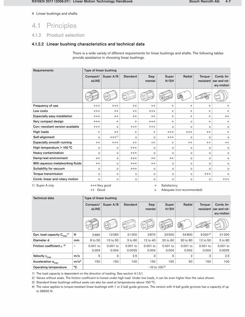
4-7Bosch Rexroth AG
4 Linear bushings and shafts
Linear Motion Technology HandbookR310EN 2017 (2006.07)
Requirements Type of linear bushing
Compact/ eLINE
Super A/B Standard Seg- mental
Super H/SH
Radial Torque- resistant
Comb. lin-ear and rot-ary motion
Frequency of use +++ +++ ++ ++ + + + +
Low costs +++ ++ ++ +++ + + + +
Especially easy installation +++ ++ ++ ++ + + + ++
Very compact design +++ + + +++ + o + +
Corr.-resistant version available +++ o +++ +++ o o o o
High loads + ++ + + +++ +++ ++ +
Self-alignment o +++1) o o +++ o o o
Especially smooth running ++ +++ ++ ++ + ++ ++ ++
High temperature > 100 °C o o +++ o o o o o
Heavy contamination o o +++ o o o o o
Damp/wet environment ++ o +++ ++ ++ o o o
With aqueous metalworking fluids ++ o +++ ++ o o o o
Suitability for vacuum o o +++ o o o o o
Torque transmission o o o o o o +++ o
Comb. linear and rotary motion o o o o o o o +++
Super A only1) +++ Very good++ Good
+ Satisfactoryo Adequate (not recommended)
4.1 Principles
4.1.2.2 Linear bushing characteristics and technical data
There is a wide variety of different requirements for linear bushings and shafts. The following tables provide assistance in choosing linear bushings.
4.1.2 Product selection
Technical data Type of linear bushing
Compact/ eLINE
Super A/B Standard Seg- mental
Super H/SH
Radial Torque- resistant
Comb. lin-ear and rot-ary motion
Dyn. load capacity Cmax1) N 5 680 12 060 21 000 3 870 23 500 54 800 9 250 4) 21 000
Diameter d mm 8 to 50 10 to 50 3 to 80 12 to 40 20 to 60 30 to 80 12 to 50 5 to 80
Friction coefficient 2) – 0.001 to 0.004
0.001 to 0.004
0.001 to 0.0025
0.001 to 0.004
0.001 to 0.004
0.001 to 0.002
0.001 to 0.004
0.001 to 0.0025
Velocity vmax m/s 5 3 2.5 3 5 2 3 2.5
Acceleration amax m/s2 150 150 100 150 150 50 150 100
Operating temperature °C –10 to 100 3)
The load capacity is dependent on the direction of loading. See section 4.1.3.1.Values without seals. The friction coefficient is lowest under high load. Under low loads, it can be even higher than the value shown.Standard linear bushings without seals can also be used at temperatures above 100 °C.The value applies to torque-resistant linear bushings with 1 or 2 ball guide grooves. The version with 4 ball guide grooves has a capacity of up to 36600 N.
1)2)3)4)
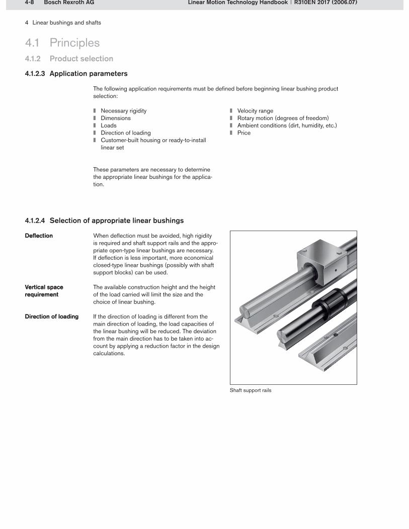
4-8 Bosch Rexroth AG
4 Linear bushings and shafts
Linear Motion Technology Handbook R310EN 2017 (2006.07)
4.1 Principles4.1.2 Product selection
4.1.2.3 Application parameters
The following application requirements must be defined before beginning linear bushing product selection:
Necessary rigidityDimensionsLoadsDirection of loadingCustomer-built housing or ready-to-install linear set
Velocity rangeRotary motion (degrees of freedom)Ambient conditions (dirt, humidity, etc.)Price
When deflection must be avoided, high rigidity is required and shaft support rails and the appro-priate open-type linear bushings are necessary. If deflection is less important, more economical closed-type linear bushings (possibly with shaft support blocks) can be used.
The available construction height and the height of the load carried will limit the size and the choice of linear bushing.
If the direction of loading is different from the main direction of loading, the load capacities of the linear bushing will be reduced. The deviation from the main direction has to be taken into ac-count by applying a reduction factor in the design calculations.
DeflectionDeflection
Vertical space requirementVertical space requirement
Direction of loadingDirection of loading
4.1.2.4 Selection of appropriate linear bushings
Shaft support rails
These parameters are necessary to determine the appropriate linear bushings for the applica-tion.

4-9Bosch Rexroth AG
4 Linear bushings and shafts
Linear Motion Technology HandbookR310EN 2017 (2006.07)
4.1.2 Product selection
4.1 Principles
It is generally best to use ready-to-install linear sets because they save time and money during design and installation. When installing linear bushings in customer-built housings, please fol-low the recommendations in the product catalog.
Not all types of linear bushings can be used when the velocity required is greater than 2 m/s.
If rotary motion must be prevented in linear bushing guideways with only one shaft, torque-resistant linear bushings must be used.
Some types of linear bushings are better suited than others for particular environmental condi-tions because of their design. There are different sealing systems or corrosion-resistant versions to cater for different applications.
An initial selection of appropriate linear bushings can be made by analyzing these parameters. The tables in sections 4.1.1.5 and 4.1.2.2 also provide assistance in this preselection process. Normally, several types of linear bushings may be suitable for a particular application. If the type of linear bushing cannot be determined because of spe-cial conditions, you can always rely on Rexroth’s many years of experience.
After selecting the type of linear bushing, the next step is to perform the design calculations.
Adjacent structureAdjacent structure
Travel speedTravel speed
Preventing rotary motionPreventing rotary motion
Environmental conditionsEnvironmental conditions
Initial selectionInitial selection
Linear set
Torque-resistant linear bushing

4-10 Bosch Rexroth AG
4 Linear bushings and shafts
Linear Motion Technology Handbook R310EN 2017 (2006.07)
4.1 Principles4.1.3 Design notes
To achieve trouble-free operation of linear bushing guides it is essential to follow the advice given below.
4.1.3.1 Influence of the direction of loading on the load capacity
In linear bushings, the direction of loading deter-mines the effective load capacity. This depends on the orientation of the direction of load applica-tion relative to the position of the rows of balls.
For each direction of load application, the maxi-mum load capacities from the product catalog are multiplied by the factor f (dynamic load capacity C) or f0 (static load capacity C0) in order to ob-tain the effective load capacity. Directions of load application for which the maximum load capacity Cmax applies are called main directions of loading. The load capacity can be optimally utilized by cor-rectly aligning the components during installation. If aligned installation is impossible or if the direc-tion of loading is not defined, the minimum load capacities Cmin apply. The corresponding load ca-pacities are given in the Rexroth product catalog.
Effective load capacityEffective load capacity
Dynamic load capacity CDynamic load capacity CStatic load capacity C0
Static load capacity C0
Main direction of loadingMain direction of loading
Super Linear Bushing SH, 20 to 25mm diameter shafts
Sample reading: For a direction of loading of = 270°, the dynamic load capacity C must be multiplied by f = 0.8 for closed-type Super
Examples of maximum and minimum effective load capacities depending on the arrangement of the rows of balls
The following example shows the effect of the direction of loading and the related f and f0 factors on a closed-type and an open-type Super Linear Bushing SH.
Linear Bushings SH with 20 to 25mm diameter shafts. The static load capacity C0 must be multi-plied by a factor f0 of 0.68.
Cmax CmaxCmin
Cmin
330o
300o
270o
240o
210o
180o150o
120o
90o
60o
30o0o
f
f(o)
f f
0.90.80.70.60.5
330o
300o
270o
240o
210o
180o150o
120o
90o
60o
30o0o
f
f(o)
0.90.80.70.60.5
– Factor f for dynamic load cases – Factor f for static load cases
Closed-type Open-type

4-11Bosch Rexroth AG
3
2
1
4 Linear bushings and shafts
Linear Motion Technology HandbookR310EN 2017 (2006.07)
4.1.3 Design notes
4.1 Principles
4.1.3.2 Design measures
In guideways with only one shaft, two linear bush-ings should be used. If there are two shafts, at least one of the shafts should be fitted with two linear bushings.
High demands are placed on the accuracy of the spacing between two shafts and their respec-tive linear bushings and on the parallelism of the shafts and the linear bushings. Inaccuracies lead to distortive stresses or overloading and therefore reduce the service life of the linear bushing guide. The product catalog gives recommended values for the maximum difference in spacing, including parallelism offsets.
Linear bushings and shafts are essentially suitable for a temperature range of –10 °C to +100 °C. For standard linear bushings with integral wiper seals and radial linear bushings with separate end seals, the maximum operating temperature is reduced to +80 °C (with brief peaks up to +100 °C). Higher temperatures are permitted for unsealed standard linear bushings. However, temperatures over +100 °C result in a reduc-tion in load capacity. At operating temperatures below freezing point, the formation of ice must be avoided.
In assemblies with rigid adjacent structures (housings, etc.) and longer distances between shaft support points, shaft deflection and the resultant pressure between the bushing edge and the shaft reduces the service life of self-sup-porting guides. The exceptions are Super Linear Bushings A, H and SH with inertial error com-pensation up to 0.5°. Please refer to the notes in section 4.1.4.7 when calculating shaft deflection.
Corrosion-resistant steels are steels to EN 10088. In very critical, corrosive environments, the parts must be checked under operating conditions. Appropriate preserving oils and lubricants must be used.
Number of linear bushingsNumber of linear bushings
Parallelism in the case of two shaftsParallelism in the case of two shafts
Operating temperaturesOperating temperatures
Shaft deflectionShaft deflection
Corrosion-resistant versionsCorrosion-resistant versions
Installation recommendations for guideways:One shaft and two linear bushingsTwo shafts and three linear bushingsTwo shafts and four linear bushings
1�2�3�
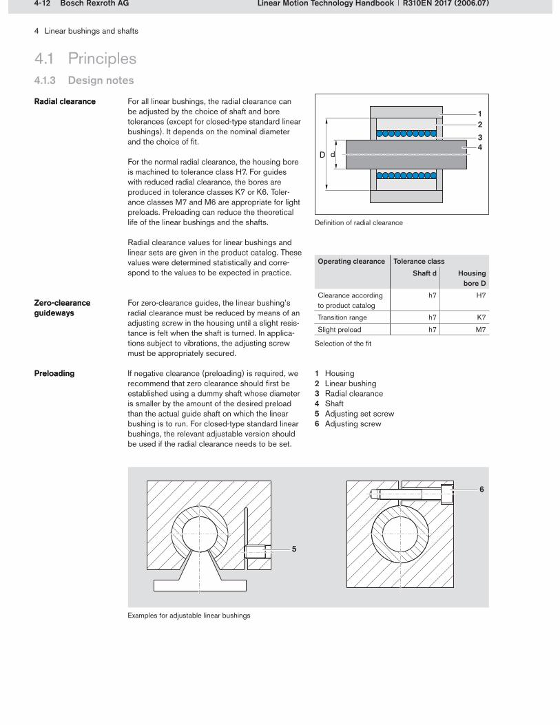
4-12 Bosch Rexroth AG
1234
4 Linear bushings and shafts
Linear Motion Technology Handbook R310EN 2017 (2006.07)
4.1.3 Design notes
4.1 Principles
For all linear bushings, the radial clearance can be adjusted by the choice of shaft and bore tolerances (except for closed-type standard linear bushings). It depends on the nominal diameter and the choice of fit.
For the normal radial clearance, the housing bore is machined to tolerance class H7. For guides with reduced radial clearance, the bores are produced in tolerance classes K7 or K6. Toler-ance classes M7 and M6 are appropriate for light preloads. Preloading can reduce the theoretical life of the linear bushings and the shafts.
Radial clearance Radial clearance
Definition of radial clearance
For zero-clearance guides, the linear bushing’s radial clearance must be reduced by means of an adjusting screw in the housing until a slight resis-tance is felt when the shaft is turned. In applica-tions subject to vibrations, the adjusting screw must be appropriately secured.
If negative clearance (preloading) is required, we recommend that zero clearance should first be established using a dummy shaft whose diameter is smaller by the amount of the desired preload than the actual guide shaft on which the linear bushing is to run. For closed-type standard linear bushings, the relevant adjustable version should be used if the radial clearance needs to be set.
Zero-clearance guidewaysZero-clearance guideways
Preloading Preloading
Operating clearance Tolerance class
Shaft d Housing bore D
Clearance according to product catalog
h7 H7
Transition range h7 K7
Slight preload h7 M7
Radial clearance values for linear bushings and linear sets are given in the product catalog. These values were determined statistically and corre-spond to the values to be expected in practice.
Selection of the fit
Examples for adjustable linear bushings
HousingLinear bushingRadial clearanceShaftAdjusting set screwAdjusting screw
1�2�3�4�5�6�
5
6

4-13Bosch Rexroth AG
4 Linear bushings and shafts
Linear Motion Technology HandbookR310EN 2017 (2006.07)
4.1.3 Design notes
4.1 Principles
The product catalog provides the tolerance values for the heights of the linear sets. These tolerance values were determined statistically and corre-spond to the values to be expected in practice.
When installing in a customer-built housing, the edge of the housing bore must be chamfered. Small linear bushings (except for Compact and eLINE linear bushings from size 12 up) can be mounted by hand. For linear bushings with larger diameters and for Compact and eLINE linear bushings, Rexroth recommends the use of a mounting tool. Under no circumstances should pressure be exerted on the wiper seals and steel holding rings (Standard linear bushings) because this might damage the ball retainers.
If a Compact or an eLINE linear bushing is slightly skewed on entering the housing bore, it will align itself as it is inserted further. Removal and re-alignment are unnecessary.
For retention of linear bushings in the housing, there are various aspects to be considered depending on the type of linear bushing. The product catalog provides the corresponding advice for each type of linear bushing under the heading “Customer-built housing.”
Rexroth’s precision steel shafts are supplied with chamfered shaft ends. The chamfering is required for sliding the linear bushing onto the shaft and protects the linear bushing’s end seals from dam-age. The linear bushing must not be misaligned when sliding it onto the shaft. Hammer blows can damage the linear bushing’s sleeve, holding rings or ball retainer. Linear bushings with seals should not be pushed over sharp edges on the shaft as this can cause damage to the lips of the seals.
Vertical dimensions Vertical dimensions
Installation in customer-built housings
Installation in customer-built housings
Mounting toolMounting tool
RetentionRetention
Sliding the bushing onto the shaftSliding the bushing onto the shaft
Installation in a customer-built housing using a mounting tool; the edge of the housing bore must be chamfered.
Vertical dimension
D -0.1-0.4
d -0.05-0.15

4-14 Bosch Rexroth AG
43
2
1
2
1
4 Linear bushings and shafts
Linear Motion Technology Handbook R310EN 2017 (2006.07)
4.1.3 Design notes
4.1 Principles
4.1.3.3 Lubrication
Linear bushings are preferably lubricated with grease (Dynalub). Grease helps to seal the lin- ear bushing and adheres to its inside surfaces. In-service lubrication is only required at long intervals.
Low lubrication requirementLow lubrication requirement
Unlike ball rail systems and ball screw drives, linear bushings and shafts require significantly less lubricant because of the smaller contact area between the rolling elements and the run-ning track.
Large contact area in ball rail systems and ball screw drives
Recommended values for load-dependent in-service lubrication, taking an eLINE linear bushing as an example
If an eLINE linear bushing is loaded with 20% of the dynamic load capacity, its service life under test conditions is 3000 km with initial lubrication
Example with in-service lubricationExample with in-service lubrication
only. With regular in-service lubrication, a service life of 15000 km can be achieved.
– With initial lubrication (no in-service lubrication)– With regular in-service lubrication
F/C
L (k
m)
F/C = load/dynamic load capacity (–)L = service life (km)
Recommended values for load- dependent in-service lubrication
Small contact area in linear bushings and shafts
Ball Contact area
1�2�
Running trackShaft
3�4�
100 000
50 000
10 000
5 000
1 000
1000.1 0.2 0.3 0.4 0.5 0.6 0.7 0.8 0.9 1.0
500

4-15Bosch Rexroth AG
4 Linear bushings and shafts
Linear Motion Technology HandbookR310EN 2017 (2006.07)
4.1.3 Design notes
4.1 Principles
In order to achieve long lubrication intervals, it is essential to perform the initial lubrication carefully and regularly check the lubrication status. The lubricants, quantities and lubrication intervals are influenced by many factors, for instance:
LoadingTravel speedMotion sequenceTemperature
The following factors reduce the lubrication intervals:
High loadsHigh speedsShort strokesLow resistance to aging in the lubricant
Lubrication intervalsLubrication intervals
General lubrication principles can be found in Chapter 2, section 2.2.5.4.
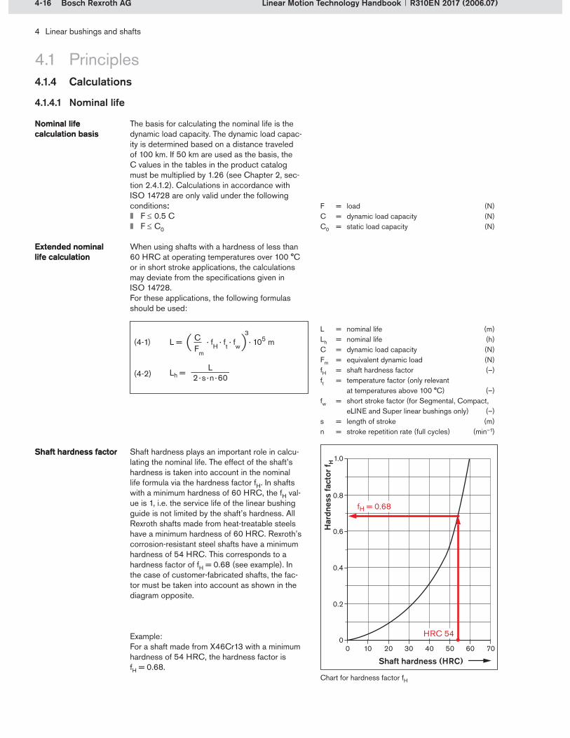
4-16 Bosch Rexroth AG
L = · fH · ft · fw · 105 mCFm
3(4-1)
(4-2)
4 Linear bushings and shafts
Linear Motion Technology Handbook R310EN 2017 (2006.07)
4.1.4 Calculations
4.1 Principles
4.1.4.1 Nominal life
The basis for calculating the nominal life is the dynamic load capacity. The dynamic load capac-ity is determined based on a distance traveled of 100 km. If 50 km are used as the basis, the C values in the tables in the product catalog must be multiplied by 1.26 (see Chapter 2, sec-tion 2.4.1.2). Calculations in accordance with ISO 14728 are only valid under the following conditions::
F 0.5 CF C0
When using shafts with a hardness of less than 60 HRC at operating temperatures over 100 °C or in short stroke applications, the calculations may deviate from the specifications given in ISO 14728.For these applications, the following formulas should be used:
Nominal life calculation basis Nominal life calculation basis
Extended nominal life calculationExtended nominal life calculation
L = nominal life (m)Lh = nominal life (h)C = dynamic load capacity (N)Fm = equivalent dynamic load (N)fH = shaft hardness factor (–)ft = temperature factor (only relevant
at temperatures above 100 °C) (–)fw = short stroke factor (for Segmental, Compact,
eLINE and Super linear bushings only) (–)s = length of stroke (m)n = stroke repetition rate (full cycles) (min–1)
Shaft hardness plays an important role in calcu-lating the nominal life. The effect of the shaft’s hardness is taken into account in the nominal life formula via the hardness factor fH. In shafts with a minimum hardness of 60 HRC, the fH val-ue is 1, i.e. the service life of the linear bushing guide is not limited by the shaft’s hardness. All Rexroth shafts made from heat-treatable steels have a minimum hardness of 60 HRC. Rexroth’s corrosion-resistant steel shafts have a minimum hardness of 54 HRC. This corresponds to a hardness factor of fH = 0.68 (see example). In the case of customer-fabricated shafts, the fac-tor must be taken into account as shown in the diagram opposite.
Shaft hardness factorShaft hardness factor
Chart for hardness factor fH
Example:For a shaft made from X46Cr13 with a minimum hardness of 54 HRC, the hardness factor is fH = 0.68.
F = load (N)C = dynamic load capacity (N) C0 = static load capacity (N)
1.0
0.8
0.6
0.4
0.2
010 20 30 40 50 60 700
HRC 54
fH = 0.68
Har
dnes
s fa
ctor
f H
Shaft hardness (HRC)
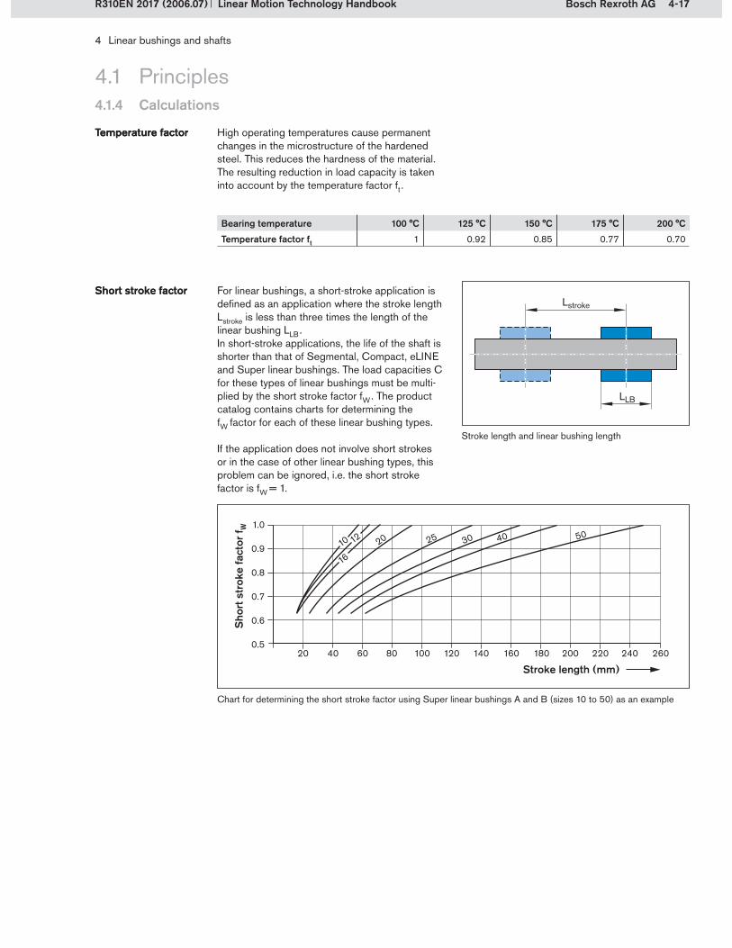
4-17Bosch Rexroth AG
4 Linear bushings and shafts
Linear Motion Technology HandbookR310EN 2017 (2006.07)
4.1.4 Calculations
4.1 Principles
High operating temperatures cause permanent changes in the microstructure of the hardened steel. This reduces the hardness of the material. The resulting reduction in load capacity is taken into account by the temperature factor ft .
Temperature factorTemperature factor
For linear bushings, a short-stroke application is defined as an application where the stroke length Lstroke is less than three times the length of the linear bushing LLB . In short-stroke applications, the life of the shaft is shorter than that of Segmental, Compact, eLINE and Super linear bushings. The load capacities C for these types of linear bushings must be multi-plied by the short stroke factor fW . The product catalog contains charts for determining the fW factor for each of these linear bushing types.
If the application does not involve short strokes or in the case of other linear bushing types, this problem can be ignored, i.e. the short stroke factor is fW = 1.
Short stroke factorShort stroke factor
Stroke length and linear bushing length
Chart for determining the short stroke factor using Super linear bushings A and B (sizes 10 to 50) as an example
Stroke length (mm)
Bearing temperature 100 °C 125 °C 150 °C 175 °C 200 °C
Temperature factor ft 1 0.92 0.85 0.77 0.70S
hort
str
oke
fact
or f W
1.0
0.9
0.8
0.7
0.6
0.520 40 60 80 100 120 140 160 180 200 220 240 260
10 12
16
20 25 30 40 50
LLB
Lstroke
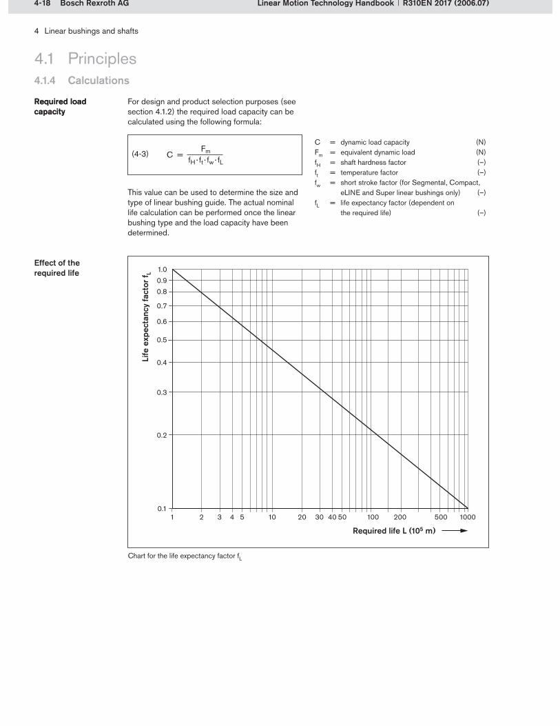
4-18 Bosch Rexroth AG
(4-3)
4 Linear bushings and shafts
Linear Motion Technology Handbook R310EN 2017 (2006.07)
4.1.4 Calculations
4.1 Principles
For design and product selection purposes (see section 4.1.2) the required load capacity can be calculated using the following formula:
Required load capacityRequired load capacity
C = dynamic load capacity (N)Fm = equivalent dynamic load (N)fH = shaft hardness factor (–)ft = temperature factor (–)fw = short stroke factor (for Segmental, Compact,
eLINE and Super linear bushings only) (–)fL = life expectancy factor (dependent on
the required life) (–)
This value can be used to determine the size and type of linear bushing guide. The actual nominal life calculation can be performed once the linear bushing type and the load capacity have been determined.
Effect of the required life 1.0
0.90.8
0.7
0.6
0.5
0.4
0.3
0.2
0.11 2 3 4 5 10 20 4030 50 100 200 500 1000
Required life L (105 m)
Life
exp
ecta
ncy
fact
or f L
Chart for the life expectancy factor fL

4-19Bosch Rexroth AG
(4-4)
(4-5)
4 Linear bushings and shafts
Linear Motion Technology HandbookR310EN 2017 (2006.07)
4.1.4 Calculations
4.1 Principles
4.1.4.2 Equivalent dynamic load on bearing
When there are varying bearing loads in the same direction of loading, the equivalent dynamic load Fm is calculated as follows, using formula (4-4):
Varying bearing loads for the same direc-tion of loading
Varying bearing loads for the same direc-tion of loading
Example of varying individual loads and the corresponding discrete travel steps over a cycle
4.1.4.3 Resulting load
If the linear bushing is affected by several forces from different load directions at the same time, the resulting load must be determined from all the forces present.
Forces from different directionsForces from different directions
= individual loads from different directions (N)
= resultant load (N)k = number of forces from different
directions (–)
Forces from different directions (example)
Then the angle of the resultant load is calculated. With this angle, the factor f is determined from the load direction chart. If the load direction can-not be determined, all further calculations must be based on the minimum load capacity (see also section 4.1.3.1).
Fm = equivalent dynamic load (N)F1 ... Fn = discrete dynamic load steps (N)qs1 ... qsn = discrete travel steps for F1 ... Fn (%)n = number of phases (–)s = distance traveled (mm)
Phase 1 Phase 2 Phase 3
Fm = F1 · + F2 · + ... + Fn · 3 qsn
100%qs2
100%qs1
100% 3 3 3
200
300
400
500
100
0250
F1
F2
qs1 = 25% qs2 = 25% qs3 = 50%
F3 F3
500 750 10000s (mm)
F (N
)

4-20 Bosch Rexroth AG
(4-6)
qs2
qs1
qs3
F2 2
F3 2
F1 2
F2 1F1 1
F1 3
F1 3
x+
y+
z+
(4-7)
4 Linear bushings and shafts
Linear Motion Technology Handbook R310EN 2017 (2006.07)
4.1.4 Calculations
4.1 Principles
4.1.4.4 Varying bearing loads from varying load directions
When there are both varying bearing loads and varying load directions, the equivalent dynamic load Fm is calculated as follows:
The resultant load for each phase must be de-termined from all the forces present (see section 4.1.4.3).
For each individual phase n:
Varying bearing loads and load directions Varying bearing loads and load directions
The resultant loads for all the individual phases are then used to calculate the equivalent dynamic load (see section 4.1.4.2).
Example of varying individual loads from different directions and the corresponding discrete travel steps over a cycle
The equivalent dynamic load Fm is subsequently used to calculate the life as shown in section 4.1.4.1.
= resultant load during phase n (N)
= individual loads from different directions in phase 1 ... n (N)
k = number of different load directions during phase n (–)
n = number of phases with different bearing loads (–)
Fm = equivalent dynamic load (N)Fres 1 ... Fres n = resultant load in phases 1 ... n (N)qs1 ... qsn = discrete travel steps for Fres 1 ... Fres n (%)
+ ... +Fm = Fres1 · qs1
100% 3
3 + Fres 2 ·
qs2
100%
3 Fres n ·
qsn
100%
3

4-21Bosch Rexroth AG
Fcomb = Fres + C · M
Mt(4-8)
qs2
qs1
qs3
M3
M2
M1
M3
L = · 105 mMtMm
3(4-9)
(4-10)
4 Linear bushings and shafts
Linear Motion Technology HandbookR310EN 2017 (2006.07)
4.1.4 Calculations
4.1 Principles
4.1.4.5 Torque considerations for torque-resistant linear bushings
If the bushing is simultaneously subjected to a radial load and a torque (moment about the travel axis), the equivalent total load has to be deter-mined.
Combined loadCombined load
Combined radial load and torqueFcomb = equivalent total load (N)Fres = resultant radial load (N)C = dynamic load capacity (N)M = torque (Nm)Mt = load moment (Nm)
In the case of purely torque loads, the life is cal-culated using the formula (4-9):
Pure torque loadPure torque load
Varying individual torque loads and corresponding discrete travel steps (example)
Mm = equivalent dynamic torque (Nm)M1 ... Mn = individual torque steps (Nm)qs1 ... qsn = discrete travel steps for M1 ... Mn (%)
The hardness factor fH and the temperature factor ft are set to 1 when calculating torque- resistant linear bushings because only shafts with a hardness of 60 HRC may be used and the operating temperature may not exceed 100 °C.
L = nominal life (m)Mm = equivalent dynamic torque (Nm)Mt = load moment (Nm)
The equivalent dynamic torque Mm in the case of varying individual torque loads is calculated using the formula (4-10):
For n phases, the equivalent dynamic bearing load Fm is calculated from the equivalent total loads for the individual phases and the corre-sponding discrete travel steps as shown in the formula (4-7).
Mm = M1 · + M2 · + ... + Mn · 3 qsn
100%qs2
100%qs1
100% 3 3 3

4-22 Bosch Rexroth AG
fm = f · · lW + b
3 · blW + b
3 · a
tan ! = · (3b2 – lW2 + a2)F · a
6 · E · I · lW
f = ·F · lW
3
3 · E · Ia2 · b2
lW4
F
b
x
a
f f m
A BlW
!
(4-11)
4 Linear bushings and shafts
Linear Motion Technology Handbook R310EN 2017 (2006.07)
4.1.4 Calculations
4.1 Principles
4.1.4.6 Static load safety factor
The static load safety factor gives the margin of safety against inadmissible permanent defor-mation on rolling elements and raceways. It is calculated using the formula (4-11):
4.1.4.7 Shaft deflection
When steel shafts are used as guideways for linear bushings the shaft deflection must be kept within certain limits to avoid any reduction in their functionality and service life. For Super linear bushings A, H and SH, there are no reductions in load capacity or service life up to a shaft de-flection of 0.5°.
To facilitate calculation of the deflection, the prod-uct catalog contains tables listing the following details:
The most commonly occurring bending load cases with the associated deflection equationsThe formulas for calculating the shaft incli-nation in the linear bushing (tan ) and the permissible shaft inclination valuesThe values for E · I, dependent on the shaft diameter
Example of the details in the product catalog for the deflection curve in a typical load case with the corre-sponding formulas for deflection and shaft inclination
F = individual load (N)f = deflection at the load application point (mm)fm = maximum deflection (mm) = shaft inclination at load application point (°)lW = shaft length (mm)E = elasticity modulus (N/mm2)I = planar moment of inertia (mm4)a, b = lever arm lengths between load and
supports (mm)
S0 = static load safety factor (–)C0 = static load capacity (N)F0 max = maximum load (N)
Deflection at x = b:
Maximum deflection:
Shaft inclination at x = b:

4-23Bosch Rexroth AG
90
690
700
1
4
2
5
4 Linear bushings and shafts
Linear Motion Technology HandbookR310EN 2017 (2006.07)
4.1 Principles
Slide (m = 30 kg)Load (m = 50 kg)Center of gravity of slide and load
1�2�3�
Linear bushingsPrecision steel shafts
4�5�
Curing oven
A slide with a dead weight of 30 kg carries a 50kg load. Two parallel shafts are used to guide the slide into the oven. The shafts are fastened to the slide. The linear bushings are stationary and mounted to the oven.
Load acting on the two shafts (weight of slide and load): 80 kgTwo support points per shaft approx. 90 mm apartA maximum of 100 °C heat radiation can be expected in the bearing area.Manual operation with approx. 6 strokes per hour (0.1/minute)
Technical data of the application Technical data of the application
4.1.5 Calculation example
Design calculations for the bearings incl. determination of the shaft diameter and selec-tion of the appropriate linear bushing and shaft combinationNominal life calculationChecking the operating safety using the static load safety factor
Necessary calculationsNecessary calculations
Stroke length: 700 mmCentre of gravity approx. 690 mm away from the rear bushing centerlineUse of precision steel shafts with a hardness of at least 60 HRCThe required service life is at least 10 years under 24 hours a day operation.
3
Calculation example for a curing oven

4-24 Bosch Rexroth AG
BB AA
a = 90 mmb = 600 mmlW = 690 mm
FA
lW
F
b a
FB
4 Linear bushings and shafts
Linear Motion Technology Handbook R310EN 2017 (2006.07)
4.1.5 Calculation example
4.1 Principles
Total load acting on one linear bushing
For a shaft hardness of 60 HRC, the reading from the chart for hardness factor fH in section 4.1.4.1, sub-section “Shaft hardness factor”, gives a value of fH = 1.
Determination of the linear bushing sizeDetermination of the linear bushing size
The life expectancy factor fL is calculated from the required service life:
According to the chart in section 4.1.4.1, sub- section “Effect of the required life”, the life expec-tancy factor is fL = 0.50. The maximum load on linear bushing B is F = 3100 N. The required load capacity C is calculated using the formula (4-3):
According to the table in section 4.1.4.1, sub-section “Temperature factor”, the temperature factor ft for 100 °C is ft = 1.
A Super linear bushing A is selected because of the expected shaft deflection. The product cata-log is then consulted to determine which of these linear bushings will meet the following conditions for a maximum load FB = 3100 N:
F C0 minF 0.5 Cmin
This results in the selection of a Super linear bushing A with a shaft diameter of 40h7 and Cmin = 8240 N and C0min = 4350 N.
For calculating the nominal life, the maximum load FB is taken as the equivalent dynamic total load Fm .
FA = FB - F = 3100 N - 400 N = 2700 N
= 392 N 400 N
F = 0.5 · m · g = 0.5 · (30 + 50) kg · 9.81 m/s2
FB = F · = 400 N · = 3067 NlWa
690 mm90 mm
3100 N
L = 7.36 · 105 m
L = Lh · 2 · s · n · 60 = 87600 h · 2 · 0.7 m · 0.1 min-1 · 60 min/h
Lh = 10 · 365 · 24 h = 87600 h
3100 N1 · 1 · 0.50 · 1
FfH · ft · fL · fw
C = = = 6200 N
Load per shaft:Bearing design calculation (station-ary application)
Bearing design calculation (station-ary application)
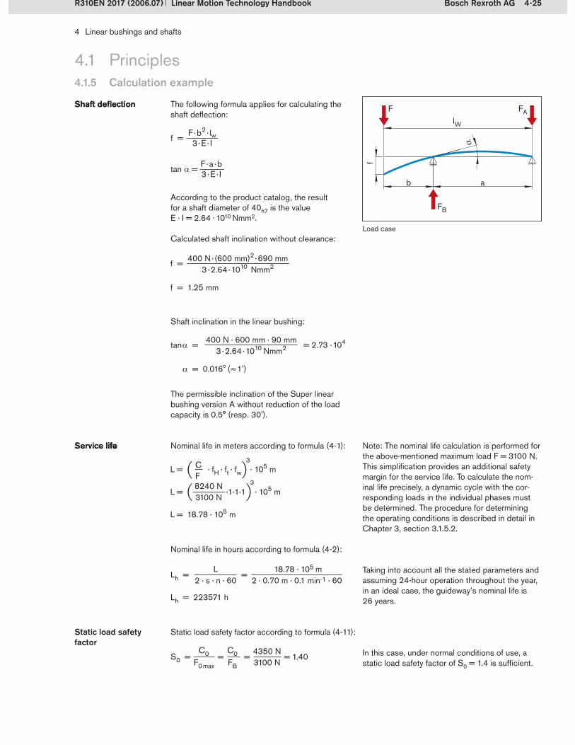
4-25Bosch Rexroth AG
FA
FB
FlW
b a
f
4 Linear bushings and shafts
Linear Motion Technology HandbookR310EN 2017 (2006.07)
4.1.5 Calculation example
4.1 Principles
According to the product catalog, the result for a shaft diameter of 40h7 is the value E · I = 2.64 . 1010 Nmm2.
Calculated shaft inclination without clearance:
Shaft inclination in the linear bushing:
The permissible inclination of the Super linear bushing version A without reduction of the load capacity is 0.5° (resp. 30').
Note: The nominal life calculation is performed for the above-mentioned maximum load F = 3100 N. This simplification provides an additional safety margin for the service life. To calculate the nom-inal life precisely, a dynamic cycle with the cor-responding loads in the individual phases must be determined. The procedure for determining the operating conditions is described in detail in Chapter 3, section 3.1.5.2.
Nominal life in hours according to formula (4-2):
Taking into account all the stated parameters and assuming 24-hour operation throughout the year, in an ideal case, the guideway’s nominal life is 26 years.
In this case, under normal conditions of use, a static load safety factor of S0 = 1.4 is sufficient.
Static load safety factor
Load case
The following formula applies for calculating the shaft deflection:
Shaft deflectionShaft deflection
Static load safety factor according to formula (4-11):
Nominal life in meters according to formula (4-1):Service life lifeService life life
f =400 N · (600 mm)2 · 690 mm
3 · 2.64 · 1010 Nmm2
f = 1.25 mm
tan = = 2.73 · 104 400 N · 600 mm · 90 mm3 · 2.64 · 1010 Nmm2
= 0.016 ( 1')
L = · fH · ft · fw · 105 m
L = ·1·1·1 · 105 m
L = 18.78 · 105 m
CF
3
8240 N3100 N
3
4350 N3100 N
S0 = = = = 1.40C0
F0 max
C0FB
Lh = 223571 h
Lh = =L
2 · s · n · 6018.78 · 105 m
2 · 0.70 m · 0.1 min-1 · 60
!
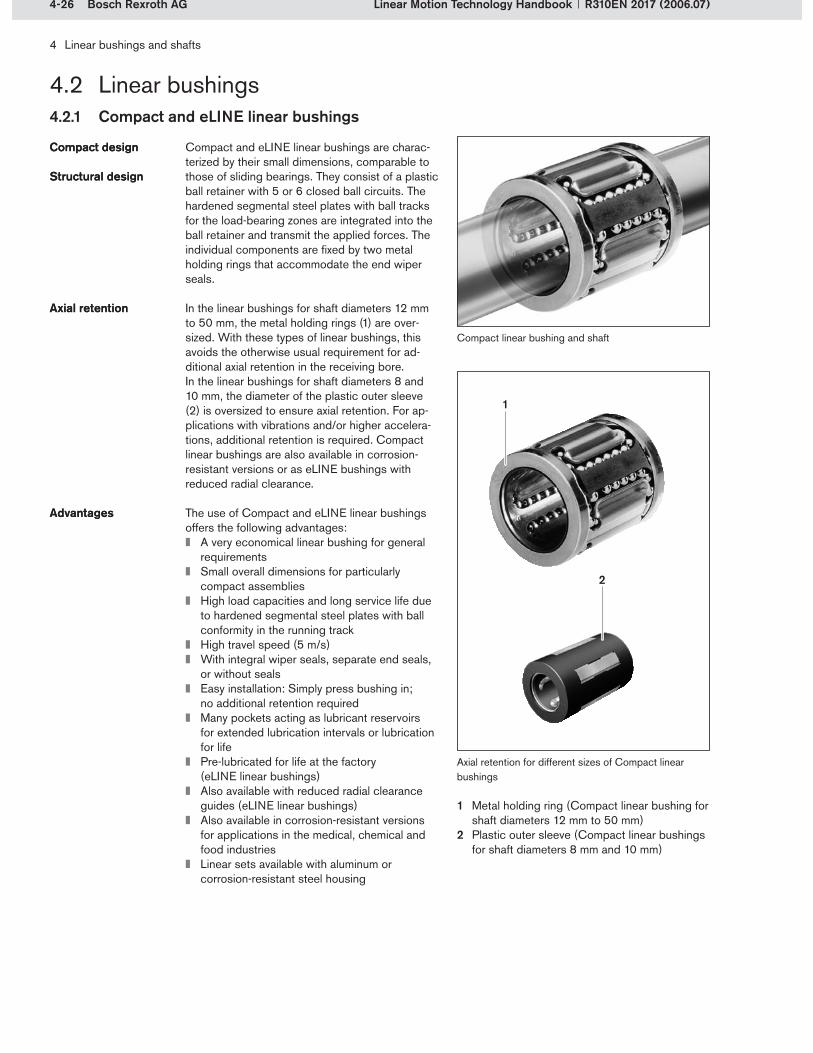
4-26 Bosch Rexroth AG
1
2
4 Linear bushings and shafts
Linear Motion Technology Handbook R310EN 2017 (2006.07)
4.2 Linear bushings4.2.1 Compact and eLINE linear bushings
Compact and eLINE linear bushings are charac-terized by their small dimensions, comparable to those of sliding bearings. They consist of a plastic ball retainer with 5 or 6 closed ball circuits. The hardened segmental steel plates with ball tracks for the load-bearing zones are integrated into the ball retainer and transmit the applied forces. The individual components are fixed by two metal holding rings that accommodate the end wiper seals.
In the linear bushings for shaft diameters 12 mm to 50 mm, the metal holding rings (1) are over-sized. With these types of linear bushings, this avoids the otherwise usual requirement for ad-ditional axial retention in the receiving bore. In the linear bushings for shaft diameters 8 and 10 mm, the diameter of the plastic outer sleeve (2) is oversized to ensure axial retention. For ap-plications with vibrations and/or higher accelera-tions, additional retention is required. Compact linear bushings are also available in corrosion-resistant versions or as eLINE bushings with reduced radial clearance.
The use of Compact and eLINE linear bushings offers the following advantages:
A very economical linear bushing for general requirementsSmall overall dimensions for particularly compact assembliesHigh load capacities and long service life due to hardened segmental steel plates with ball conformity in the running trackHigh travel speed (5 m/s)With integral wiper seals, separate end seals, or without sealsEasy installation: Simply press bushing in; no additional retention requiredMany pockets acting as lubricant reservoirs for extended lubrication intervals or lubrication for lifePre-lubricated for life at the factory (eLINE linear bushings)Also available with reduced radial clearance guides (eLINE linear bushings)Also available in corrosion-resistant versions for applications in the medical, chemical and food industriesLinear sets available with aluminum or corrosion-resistant steel housing
Compact designCompact design
Structural designStructural design
Axial retentionAxial retention
AdvantagesAdvantages
Axial retention for different sizes of Compact linear bushings
Metal holding ring (Compact linear bushing for shaft diameters 12 mm to 50 mm)Plastic outer sleeve (Compact linear bushings for shaft diameters 8 mm and 10 mm)
1�
2�
Compact linear bushing and shaft

4-27Bosch Rexroth AG
21
4 Linear bushings and shafts
Linear Motion Technology HandbookR310EN 2017 (2006.07)
Super linear bushings A and B have steel inserts with ground ball tracks and optimized ball entry zone geometry for especially smooth running and long life.
They consist of a plastic ball retainer with 5 or 6 closed ball circuits, depending on the diameter. The hardened segmental steel plates with ground ball tracks are integrated into the plastic outer sleeve. These segments are the load-bearing elements. The plastic outer sleeve forms a closed shell that covers the balls in the return tracks.
Super linear bushings are sealed either with inte-gral wiper seals or separate end seals. If separate end seals are used, these are held in place by a metal case. The case is oversized and can also be used for axial retention of the linear bushing. The integral wiper seals are floating seals (1), which provide very good sealing even when the linear bushing rocks. This significantly prolongs the bushing’s life.
Because of the slightly crowned outer contours of the segmental steel plates (2), the Super linear bushing A can compensate for alignments errors of up to 0.5° between the shaft and the receiving bore. Alignment errors are caused by:
Manufacturing inaccuraciesMounting errorsShaft deflection
Angular self-adjustment ensures that the balls enter the load-bearing zone smoothly and that the load is distributed evenly across the whole row of balls and over the full travel stroke. This also prevents any critical pressure between the bush-ing edge and the shaft due to distortive stresses. There is no reduction in load capacity or service life and the bushing runs exceptionally smoothly.However, the self-aligning feature cannot com-pensate for parallelism offsets between the shafts in a table guide.
The travel profile opposite shows a comparison with a conventional linear bushing. The example is based on a load of 800 N and an alignment error of approx. 8' (0.13°), due to shaft deflection. Self-' (0.13°), due to shaft deflection. Self- (0.13°), due to shaft deflection. Self-alignment may cause a slight rocking effect. Two Super linear bushings must therefore be used on at least one of the guideway’s shafts.
Smooth running Long service lifeSmooth running Long service life
Structural designStructural design
SealingSealing
Super linear bushing ASuper linear bushing ASelf-alignmentSelf-alignment
Angular self-adjustmentAngular self-adjustment
Rocking effectRocking effect
4.2.2 Super linear bushings A and B
4.2 Linear bushings
Floating seals and self-alignment
Alignment error and rocking effect
Travel profiles recorded at the same speed of travel
– Conventional linear bushing, size 20– Super linear bushing A, size 20
Travel
Fric
tion
(N)
Super linear bushing A

4-28 Bosch Rexroth AG
4 Linear bushings and shafts
Linear Motion Technology Handbook R310EN 2017 (2006.07)
4.2 Linear bushings4.2.2 Super linear bushings A and B
Super linear bushings B have no self-alignment function. They are the solution for applications in which only one linear bushing is used per shaft and the linear bushing may not rock on the shaft.
Since Super linear bushings A and B provide exceptional conformity between the balls and the ground ball tracks, higher load capacities are possible compared to Standard linear bushings of the same dimensions.
The use of Super linear bushings A or B offers the following advantages:
An economical linear bushing for demanding applicationsVery good, low-noise running performanceHigh dynamic load capacityHigh acceleration and high travel speed thanks to good ball guidance and wear-resistant ball retainerHigh rigidityWith integral wiper seals, separate end seals, or without sealsIdentical installation dimensions ensure inter-changeability with Super linear bushings H and SH and also with Standard linear bushingsLinear sets available with aluminum or corrosion-resistant steel housing
Super linear bushing BSuper linear bushing B
Super linear bushings A and BSuper linear bushings A and B
AdvantagesAdvantages
Super linear bushing B without self-alignment

4-29Bosch Rexroth AG
1
2
3
4 Linear bushings and shafts
Linear Motion Technology HandbookR310EN 2017 (2006.07)
4.2 Linear bushings4.2.3 Standard linear bushings
Standard linear bushings are so called because they were the first to be developed. Their preci-sion and therefore their load-bearing capacity and travel performance have been constantly improved through continuous further develop-ment. In the meantime, since other types of linear bushings with sometimes significantly higher per-formances have been developed, Standard linear bushings are now primarily used for applications in harsh environments. Typical applications are found in the woodworking industry, foundries and cement factories.
The outer sleeve of Standard linear bushings is hardened and ground. The shaft diameter determines the number of rows of balls. Standard linear bushings can have from 4 to 6 rows. The balls run in closed circuits inside the sheet steel ball retainer. The ball retainer is fixed by holding or sealing rings in grooves in the outer sleeve. The steel ball retainer makes Standard linear bushings especially robust.
Standard linear bushings are available in three forms: closed-type, adjustable and open-type. For use at very high temperatures, there is also an unsealed version.Closed-type Standard linear bushings are also available in versions made entirely from corrosion-resistant steel and are used, among other areas, in the medical, chemical and food industries.When long stroke lengths are required, open-type Standard linear bushings are used with shaft sup-port rails. The shaft support rail prevents the shaft from deflecting.
The use of Standard linear bushings offers the following advantages:
Long service lifeHigh precisionLow frictionRobust all-metal designSuitable for temperature ranges above 100 °C or vacuum applicationsMany pockets acting as lubricant reservoirs for extended lubrication intervals or lubrication for lifeWith integral wiper seals or without sealsVarious flanged versions availableLinear sets available with cast iron housing
Robust linear bush-ings for use under harsh conditions
Robust linear bush-ings for use under harsh conditions
Structural designStructural design
Construction formsConstruction forms
AdvantagesAdvantages
Forms of Standard linear bushings
Closed-type Standard linear bushingAdjustable Standard linear bushingOpen-type Standard linear bushing
1�2�3�
Adjustable Standard linear bushing

4-30 Bosch Rexroth AG
4 Linear bushings and shafts
Linear Motion Technology Handbook R310EN 2017 (2006.07)
4.2 Linear bushings
Segmental linear bushing
Segmental linear bushings are the shortest types of linear bushing. They consist of a plastic ball retainer with hardened segmental steel plates that are fixed in the ball retainer by two plastic rings. Either the wiper sealing ring or a metal case with integral sealing ring are used for axial retention.
For applications in corrosive conditions or where there are heavy requirements on cleanliness, such as, for instance, in the food industry, semi-conductor manufacture or the medical equipment industry, these linear bushings are also available in corrosion-resistant versions.
The use of Segmental linear bushings offers the following advantages:
Low-noise operationLow weightAs linear sets with reinforced plastic housings, they represent a low-cost solution for general requirements.The shortest type of linear bushing due to its design, it provides the longest stroke for a given shaft length.With separate seals or without seals
Shortest linear bushing typeShortest linear bushing type
Structural designStructural design
Corrosion-resistant versionCorrosion-resistant version
AdvantagesAdvantages
4.2.4 Segmental linear bushings
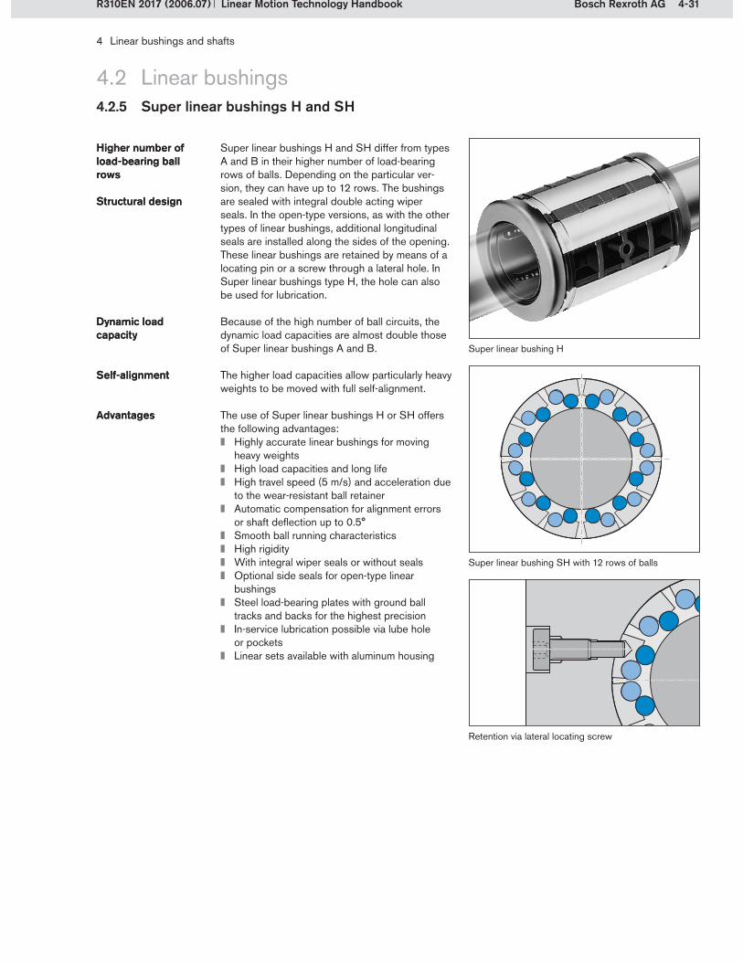
4-31Bosch Rexroth AG
4 Linear bushings and shafts
Linear Motion Technology HandbookR310EN 2017 (2006.07)
4.2 Linear bushings4.2.5 Super linear bushings H and SH
Super linear bushings H and SH differ from types A and B in their higher number of load-bearing rows of balls. Depending on the particular ver-sion, they can have up to 12 rows. The bushings are sealed with integral double acting wiper seals. In the open-type versions, as with the other types of linear bushings, additional longitudinal seals are installed along the sides of the opening. These linear bushings are retained by means of a locating pin or a screw through a lateral hole. In Super linear bushings type H, the hole can also be used for lubrication.
Because of the high number of ball circuits, the dynamic load capacities are almost double those of Super linear bushings A and B.
The higher load capacities allow particularly heavy weights to be moved with full self-alignment.
Higher number of load-bearing ball rows
Higher number of load-bearing ball rows
Structural designStructural design
Dynamic load capacityDynamic load capacity
Self-alignmentSelf-alignment
The use of Super linear bushings H or SH offers the following advantages:
Highly accurate linear bushings for moving heavy weightsHigh load capacities and long lifeHigh travel speed (5 m/s) and acceleration due to the wear-resistant ball retainerAutomatic compensation for alignment errors or shaft deflection up to 0.5°Smooth ball running characteristicsHigh rigidityWith integral wiper seals or without sealsOptional side seals for open-type linear bushingsSteel load-bearing plates with ground ball tracks and backs for the highest precisionIn-service lubrication possible via lube hole or pocketsLinear sets available with aluminum housing
AdvantagesAdvantages
Super linear bushing SH with 12 rows of balls
Retention via lateral locating screw
Super linear bushing H

4-32 Bosch Rexroth AG
1 2
4 Linear bushings and shafts
Linear Motion Technology Handbook R310EN 2017 (2006.07)
4.2 Linear bushings
Radial linear bushing
Principle of radial ball circulation
Load-bearing ballsNon-loaded balls in the return zone
1�2�
4.2.6 Radial linear bushings
In Radial linear bushings, the balls are recircu-lated outwards through radially arranged return raceways. This more than doubles the number of load-bearing rows of balls compared to con-ventional linear bushings and extends the load-bearing zones, which results in very high load capacities and high rigidity.
Radial linear bushings are available only as open-type versions. They consist of a hardened and ground steel sleeve with a plastic ball retainer in which 12 closed ball circuits and two retaining rings are integrated. The load-bearing balls are guided in several tracks in the plastic ball retainer, directed radially outwards and then conducted back to the load-bearing zone via ball return bores. Because of their characteristics, these linear bushings are suitable for use in machine tools, numerous special machines, and transfer and automation systems.
The use of radial linear bushings offers the follow-ing advantages:
Highly precise linear bushingsSuitable for moving very heavy weightsVery high load capacitiesVery high rigidityVery smooth operationWith integral wiper seals and side seals (fully sealed), with separate end seals, or without sealsHeavy-duty version with a degree of freedom in the circumferential directionFor applications where other linear guides might be susceptible to distortive stresses be-cause of inaccuracies in supporting structuresLinear sets available with steel housingRadial Compact sets available for highly compact designs
Radial ball recirculationRadial ball recirculation
High load capacities and rigidityHigh load capacities and rigidity
Structural designStructural design
AdvantagesAdvantages

4-33Bosch Rexroth AG
4321 5
4 Linear bushings and shafts
Linear Motion Technology HandbookR310EN 2017 (2006.07)
4.2 Linear bushings4.2.7 Torque-resistant linear bushings
A torque-resistant linear bushing can absorb a torque around the travel axis. Torque-resistant linear bushings were developed as machines elements enabling true, i.e. torsionally stiff, linear motion with only one shaft. This compact design meets the requirements of many equipment and special machinery construction sectors. The basic structure corresponds to that of Super linear bushings B, but with one or two rows of balls at a lower level (2). The shaft (1) has one or two ball guide grooves in which the lower-level ball rows are guided and can transmit torque forces. The guide grooves in the shaft and the relevant steel inserts (3) in the linear bushing have a Gothic profile. This profile forms a 4-point contact with the balls and enables the transmission of moment loads in both directions around the travel axis.
An adjustment screw (4) is inserted into the receiving housing and engages with a counter-sunk area on the steel insert (3) belonging to the lower-level row of balls. The adjustment screw allows the torque-resistant linear bushing to be adjusted to zero clearance. A locking nut (5) secures the adjustment screw.
For special applications, torque-resistant linear bushings can be provided with up to four ground ball guide grooves. These are capable of trans-ferring higher torques. Another version is the Torque-resistant Compact linear bushing. The compact linear bushing version has a smaller out-side diameter and is fitted with a more compact adjusting and locking screw. The compact design makes insertion into sleeves particularly easy.
The use of Torque-resistant linear bushings offers the following advantages:
Axially and radially true linear motion with only one shaftLarge choice of formatsWith separate seals or without sealsVarious flanged versions available With steel or aluminum housings in various formats
Torque-resistant linear guides Torque-resistant linear guides
Structural designStructural design
Gothic profileGothic profile
Adjusting for zero clearanceAdjusting for zero clearance
VersionsVersions
AdvantagesAdvantages
Structure of a Torque-resistant linear bushing and shaft with one ball guide groove (represented as a linear set)
Torque-resistant linear bushing and shaft with two ball guide grooves
Version with four ball guide grooves and flange
Torque-resistant Compact linear bushing
Torque-resistant linear bushing

4-34 Bosch Rexroth AG
1
4 Linear bushings and shafts
Linear Motion Technology Handbook R310EN 2017 (2006.07)
4.2 Linear bushings
Structural design of a linear bushing for combined linear and rotary motion with needle bearings (1)
Linear bushing for combined linear and rotary motion
4.2.8 Linear bushings for combined linear and rotary motion
Linear bushings for combined linear and rotary motion are supplied with deep-groove ball bear-ings or needle bearings. They are suitable for ap-plications involving both linear and rotary motion.
The use of this type of linear bushings offers the following advantages:
Precise guidance with high load capacitiesHigh rotational speed and low frictionSuitable for linear applications with additional rotary motionSuitable for gripping and swiveling functions Suitable for winding applications
Deep-groove ball bearings Needle bearings
Deep-groove ball bearings Needle bearings
AdvantagesAdvantages

4-35Bosch Rexroth AG
4 Linear bushings and shafts
Linear Motion Technology HandbookR310EN 2017 (2006.07)
Linear sets are complete bearing units consist-ing of a housing with one or two linear bushings. They are available in many different configura-tions. Because of their rationalized construction and fabrication, linear sets offer users significant cost advantages over customer-built designs. The housings can be easily aligned during mounting, thereby avoiding distortive stresses on the linear bushings.
The high precision ensures the linear bushings’ operational reliability and makes the units fully interchangeable.
Complete bearing unitsComplete bearing units
Cost advantagesCost advantages
InterchangeabilityInterchangeability
Type of linear bushing Designs Versions
Compact linear bushingeLINE linear bushing
Adjustable/non-adjustableNormal/corrosion-resistantSingle/tandem
Super linear bushing ASuper linear bushing B
Cast iron/aluminum housingAdjustable/non-adjustableWith side openingWith flangeSingle/tandem (aluminum only)
Standard linear bushing Closed/open typeAdjustable/non-adjustableWith side openingWith flange
Segmental linear bushing Normal/corrosion-resistant
Super linear bushing HSuper linear bushing SH
Closed/open typeAdjustable/non-adjustableWith side opening
Radial linear bushing Adjustable/non-adjustableWith side openingRadial Compact sets
Torque-resistant linear bushing
With 1, 2 or 4 ball guide groovesSingle/tandemSteel/aluminumHousing/sleeveSleeve with flange
4.3 Linear sets
Linear bushing guide with two linear sets

4-36 Bosch Rexroth AG
4 Linear bushings and shafts
Linear Motion Technology Handbook R310EN 2017 (2006.07)
4.3 Linear sets
Linear sets provide high rigidity regardless of the load direction. Just as with linear bushings, for linear sets also the effect of the load direction on load capacity must be taken into account. The high precision ensures the linear bushings’ operational reliability and makes the units fully interchangeable.
High rigidityHigh rigidity
Version Applications
Closed type For high-precision guidance with extreme ease of mounting. Version with fixed working bore diameter.
Adjustable For use when zero clearance or preload is required. The desired radial clearance is established by means of an adjusting screw. These Linear Sets are adjusted to zero clearance before delivery.
Open type For long guideways when the shafts must be supported and high rigidity is required.
Open type, adjustable For use when zero clearance or preload is required. The desired radial clearance is established by means of an adjusting screw. These Linear Sets are adjusted to zero clearance before delivery.
With side opening Handles forces from all directions without reduction of load capacity.
With side opening, adjustable
For use when zero clearance or preload is required. The desired radial clearance is established by means of an adjusting screw. These Linear Sets are adjusted to zero clearance before delivery.
Corrosion-resistant Housing in corrosion and acid-resistant chrome-nickel steel for use in the food, semi-conductor, medical, pharmaceutical and chemical industries.
Flanged type This element was developed as a complement to the linear set series for use in applications requiring the shaft to be arranged at right angles to the mounting base.
Tandem type Linear set with two linear bushings for heavy loads.
Unlike linear sets, in radial compact sets the housing and the linear bushing are integrated into one element. The ball recirculation principle is the same as that of radial linear bushings.
Radial Compact sets offer decisive advantages over linear sets with radial linear bushings:
Lower height and narrower width due to compact designLower weightIncreased dimensional accuracy and closer tolerances: The radial clearance is 50% smaller and the height tolerance is up to 25% less.Fully sealed with a sealing ring and a side seal along the openingReference edge for easier mounting Predrilled holes for locating pins
Radial Compact setRadial Compact set
AdvantagesAdvantages
Linear bushing guide with two Radial Compact sets

4-37Bosch Rexroth AG
4 Linear bushings and shafts
Linear Motion Technology HandbookR310EN 2017 (2006.07)
4.4 Precision steel shafts
Precision steel shafts are available in metric diameters with various tolerances, as solid shafts and tubular shafts, made from heat-treated steel, corrosion-resistant steel or hard chrome plated steel. Rexroth supplies precision steel shafts cut to customer-specified lengths with chamfering at both ends, or machined to customers’ drawings or specifications.
Cross-section and longitudinal section through a hardened steel shaft
The diameters of the precision steel shafts are machined to tolerance classes h6 and h7.
The shafts are induction hardened and smoothed by centerless grinding. The depth of hardening is 0.4 to 3.2 mm depending on the shaft diameter. The surface hardness and depth of hardness are extremely uniform, both in the axial and in the circumferential direction. This is the reason for the excellent dimensional consistency and the long service life of the precision steel shafts.The photographs opposite show a cross-section and a longitudinal section through a hardened and ground precision steel shaft. The hardened surface zone has been made visible by polishing and caustic etching.
When steel shafts are used as round guideways for linear bushings, shaft deflection must be taken into account (see section 4.1.4.7). This occurs because of the operating loads. Deflection must be kept within certain limits in order to avoid any reduction in the functionality and service life of the assemblies.
Steel shafts intended for use as round guide-ways for linear bushings must be chamfered at the ends to prevent damage to the ball retainers or wiper seals when the linear bushing is being pushed onto the shaft.
In addition to their use as guide shafts for linear bushings, precision steel shafts are well-proven in many other applications, for instance as rollers, pistons or axles.
Tolerance classesTolerance classes
HardnessHardness
DeflectionDeflection
ChamferingChamfering
ApplicationsApplications
Types Versions
Solid shaft Heat-treated steelCorrosion-resistant steel X46Cr13Corrosion-resistant steel X90CrMoV18Hard chrome plated
Tubular shaft Heat-treated steelHard chrome plated
Precision steel shafts

4-38 Bosch Rexroth AG
4 Linear bushings and shafts
Linear Motion Technology Handbook R310EN 2017 (2006.07)
4.5 Shaft support rails
Shaft support rails are ready-to-install elements with high dimensional accuracy.Shaft support rails are designed for use with open-type linear bushings. They prevent the shaft from bending and increase the rigidity of the overall system.
The use of shaft support rails offers the following advantages:
Prevention of shaft deflection Improving the performance of linear motion guidewaysAn additional degree of freedom in the circum-ferential direction compared to profiled rail systemsSaving on complex and costly customer-built designsFor applications where other linear guides might be susceptible to distortive stresses be-cause of inaccuracies in supporting structuresAll shaft support rails are also suitable for use with corrosion-resistant shafts.
Ready-to-install elements Ready-to-install elements
RigidityRigidity
AdvantagesAdvantages
Shaft support rails
Suitability Designs Characteristics Designs Characteristics
For Super and Standard linear bushings
Low profileEspecially economicalWith flangeMaterial: aluminum
Especially economicalFor high loadsFlangelessMaterial: aluminum
Suitable for aluminum profile systemsLow profileEspecially economicalWith flangeMaterial: aluminum
With reference edgeHigh precisionFor high loadsFlangelessMaterial: steel
Low profileHigh precisionFor high loadsWith flangeMaterial: aluminum
For side fittingHigh precisionFor high loadsMaterial: aluminum
High profileHigh precisionFor high loadsWith flangeMaterial: aluminum
For Radial linear bushings
Low profileHigh precisionFor high loadsWith flangeMaterial: steel
For side fittingHigh precisionFor high loadsMaterial: steel
For Radial Compact sets
With reference edgeLow profileHigh precisionFor high loadsWith flangeMaterial: steel

4-39Bosch Rexroth AG
4 Linear bushings and shafts
Linear Motion Technology HandbookR310EN 2017 (2006.07)
4.6 Shaft support blocks
In guides with closed-type linear sets the guide shafts are fixed at the ends. Precision shaft sup-port blocks have been specially developed for this purpose.
Shaft support blocks from Rexroth provide significant cost advantages over customer-built designs. They are also highly rigid. The individual elements have a high degree of dimensional accuracy and are therefore interchangeable. The shaft support blocks are designed for easy mounting and fast alignment. Where especially high precision is required, shaft support blocks with reference edges are the best choice.
For closed-type linear setsFor closed-type linear sets
RigidityRigidity
InterchangeabilityInterchangeability
Designs Versions/special features
Spheroidal graphite cast iron
AluminumRigid shaft mounting due to extra-wide designWith reference edge
FlangedGray cast iron
AluminumFor linear sets with Compact linear bushingsFor particularly space-saving constructions
Corrosion-resistant chrome-nickel steelFor use in the food, semiconductor, pharmaceutical and chemical industriesFor particularly space-saving constructions
Shaft support block

4-40 Bosch Rexroth AG
4 Linear bushings and shafts
Linear Motion Technology Handbook R310EN 2017 (2006.07)

5-1Bosch Rexroth AG
5 Ball screw drives
Linear Motion Technology HandbookR310EN 2017 (2006.07)
5.1 Principles
In linear motion technology, the generation of “push-pull” or drive motion is just as important as precise guidance of the machine parts. Alongside rack and pinion drives and linear motors, screw drives (screw-and-nut systems) play an important role as feed mechanisms.
Screw drive overviewScrew drive overview
5.1.1 System technology
These units convert rotary motion into linear mo-tion. The most important representatives in this group of systems are acme screw drives, ball screw drives and planetary roller screw drives.
Screw drive type Description
Acme screw drive Screw drive with sliding contact between the screw and the nut
Ball screw drive Screw drive with rolling contact between the screw, rolling elements and nutRolling elements: balls
Planetary roller screw drive
Screw drive with integral planetary gear Screw drive with rolling contact between the screw and the rolling elements and between the rolling elements and the nutRolling elements: planetary rollers
In linear motion technology, ball screw drives are the most commonly used option. In the following sections, balls screw drives are dealt with in more detail.
The most important technical specifications and definitions for ball screw drives are stipulated in DIN 69051, Parts 1 to 6. This family of standards covers ball screw drives for use in machine tools, but also applies to other industry sectors.
DIN 69051 Part 1 defines ball screw drives as follows:An assembly comprising a ball screw shaft and a ball nut and which is capable of converting rotary motion into linear motion and vice versa. The roll-ing elements of the assembly are balls.
DIN standardDIN standard
Screw and nut of a ball screw assembly

5-2 Bosch Rexroth AG
4
3
B
A
5
2
1
6
C
5 Ball screw drives
Linear Motion Technology Handbook R310EN 2017 (2006.07)
5.1 Principles
Ball screw assemblies generally consist of the following components:
Ball nut with continuously recirculating rolling elementsNut housing (optional)Ball screwEnd bearings
The ball nut is installed in the component to be moved (table/carriage) either directly or using a nut housing.
5.1.1 System technology
5.1.1.1 Structural design of a ball screw assembly
Structural design of a ball screw assembly
Most ball screw assemblies are driven by a motor attached to the screw journal (1). The nut, or nut and carriage assembly, is positioned by means of the screw’s rotation (A). There are also ball screw drives which operate according to a different principle, that of the driven nut (see sec-tion 5.3.2). In this case the nut is driven directly and the screw does not turn. Depending on the application, either the nut (B) or the screw (C) will be fixed in position.
The individual elements of ball screw drives are covered in detail in the following sections.
Operating principleOperating principle
Screw journalEnd bearing (here: fixed bearing)Ball screwBall nutNut housing or customer’s carriage elementEnd bearing (here: floating bearing)
1�2�3�4�5�6�
Operating principles of ball screw assemblies

5-3Bosch Rexroth AG
1
2
5 Ball screw drives
Linear Motion Technology HandbookR310EN 2017 (2006.07)
5.1 Principles5.1.1 System technology
Gothic profile of the ball tracks in the screw and nut and contact points on the rolling elements
The balls run along a helical ball track (the thread, generally with a gothic profile) formed in a shaft. The ball nuts, too, are threaded, and it is the interaction of the ball movement along the screw ball track and along the ball nut raceways which converts rotary motion into linear motion.
ScrewScrew
Screws are specified by means of defined geo-metric parameters. These parameters are also generally used to specify the complete ball screw assembly.
Screw dimensionsScrew dimensions
Screw geometry
P = lead (linear travel/revolution) (mm)d0 = nominal screw diameter
(ball center-to-center diameter) (mm)d1 = screw outside diameter (mm)d2 = screw core diameter (mm)DW = ball diameter (mm)
Screw sizes are specified according to the nomi-nal screw diameter d0, the lead P and the ball diameter DW: d0 x P x DWThe specification for the lead P also includes the direction of rotation of the screw thread (R for right-hand or L for left-hand).
Example: 32 x 5R x 3.5 for a screw with a nominal diameter of 32 mm, lead of 5 mm, right-hand thread, and a ball diameter of 3.5 mm.
Screw sizesScrew sizes
Depending on the screw diameter, lead and ball diameter, screws can also be produced with more than one ball track. These screws are commonly called multi-start screws.
Multi-start screwsMulti-start screws
Single-start (1) and two-start (2) screw
Screws with up to four starts are technically feasible today and have also been produced where appropriate. When used in combination with multi-start nuts, the resulting assemblies can achieve higher load ratings and therefore also have a longer life expectancy.
In general, ball screws are produced with a right-hand thread. For special applications (e.g. closing or clamping movements) screws with a left-hand thread or with right and left-hand thread can be used.

5-4 Bosch Rexroth AG
5
6
7
4
2
1
3
76
5 Ball screw drives
Linear Motion Technology Handbook R310EN 2017 (2006.07)
5.1 Principles5.1.1 System technology
The ball nut is fastened to the moving machine part in the adjacent structure and converts the screw’s rotary motion into linear motion via the recirculating balls.
The main elements of a ball nut are illustrated in the following example.
Ball nutBall nut
Structural design of a ball nut
The rolling element circuit in a ball nut consists of a load-carrying zone (7) and a return zone (6).In the load-carrying zone, the rolling elements transfer the arising axial forces from the screw to the nut and vice versa. The balls execute several turns around the screw while they are in the load-carrying zone, according to the num- ber of ball track turns in the nut. In the example shown, there are 5 ball track turns. In the return zone, the balls are not loaded and are simply guided back to the load-carrying zone. The recir-culation piece (3) picks up the balls at the end of the load-carrying zone and guides them into the return zone and from the return zone back into the load-carrying zone. Various ball recirculation systems have evolved over the course of techni-cal development. The most important of these are described in the following paragraphs.
Rolling element circuitRolling element circuit
Principle of rolling element recirculation
Nut bodyRolling elements (balls)Recirculation piece (ball pick-up)Ball recirculation retaining ring
1�2�3�4�
Sealing systemBall return zoneLoad-carrying zone
5�6�7�

5-5Bosch Rexroth AG
5 Ball screw drives
Linear Motion Technology HandbookR310EN 2017 (2006.07)
5.1 Principles5.1.1 System technology
Single-turn recirculation Multiple-tube recirculation
The single-turn recirculation system recirculates the balls from just one ball track turn. A recirculating piece inserted into the nut body guides the balls over the screw shoulder and into the neighboring thread turn.
In this particular recirculation system, the balls are brought back to the threading by tubes spanning two or three ball track turns. A nut with several ball circuits will have several recirculation tubes.
Single-tube full recirculation Integrated single-bore full recirculation
In this tube-type recirculation system, the balls in a circuit are returned via a single tube that spans the entire nut length and all the ball track turns.
In this recirculation system, there is again only one recirculation duct spanning all the ball track turns. The balls are returned through a recirculation bore inside the nut. A nut designed for use with multi-start screws can comprise several ball circuits and will therefore have several recirculation bores.
Recirculation systemsRecirculation systems
All the above recirculation systems can be found in ball screw assemblies currently offered on the market. The best technical solution is the inte-grated single-bore full recirculation system with tangential ball pick-up.
The advantages of this system are:High load ratings by using the whole length of the nutQuieter running through integration of the recirculation tube into the body of the nut, resulting in a highly rigid return channel with no noise-increasing effect (does not act as a resonance body)Uniform torque profile due to tangential ball pick-up

5-6 Bosch Rexroth AG
5 Ball screw drives
Linear Motion Technology Handbook R310EN 2017 (2006.07)
5.1 Principles5.1.1 System technology
There are various nut forms and flange designs available for incorporating ball nuts into the sur-rounding structure.
Nut bodyNut body
Full flange Single-flat flange Double-flat flange
“Speed” series nut with full circular flange
“Standard” series nut with a flat on one side of the flange
“Miniature” series nut with flange flattened on both sides
The different flange shapes on the flanged nuts enable fixing even in restricted spaces. The number of flange holes is adapted to the load
Flanged nuts Flanged nuts rating and/or the potential load on the respective ball nut.
Nut form Fastening to the adjacent structure and further system characteristics
Screw-in nut Screw-in nuts are inserted directly into a mating thread in the adjacent structure.
Cylindrical nut Cylindrical nuts are used for compact constructions.The torque is transferred by a key in the nut body.The cylindrical nut is axially secured by a ring nut.
Flanged nut The flange is used to bolt the nut to the adjacent structure.The position of the flange (at the end or in the center) depends on the nut series.
Nut formsNut forms
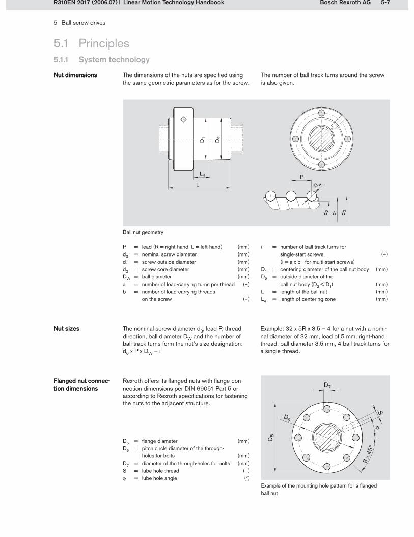
5-7Bosch Rexroth AG
L
L4
D1
D2
P
D w
d 2 d 1 d 0
!
5 Ball screw drives
Linear Motion Technology HandbookR310EN 2017 (2006.07)
5.1 Principles5.1.1 System technology
The dimensions of the nuts are specified using the same geometric parameters as for the screw.
Nut dimensionsNut dimensions
P = lead (R = right-hand, L = left-hand) (mm)d0 = nominal screw diameter (mm)d1 = screw outside diameter (mm)d2 = screw core diameter (mm)DW = ball diameter (mm)a = number of load-carrying turns per thread (–)b = number of load-carrying threads
on the screw (–)
Example of the mounting hole pattern for a flanged ball nut
Ball nut geometry
The number of ball track turns around the screw is also given.
i = number of ball track turns for single-start screws (–) (i = a x b for multi-start screws)
D1 = centering diameter of the ball nut body (mm) D2 = outside diameter of the
ball nut body (D2 < D1) (mm)L = length of the ball nut (mm)L4 = length of centering zone (mm)
Rexroth offers its flanged nuts with flange con-nection dimensions per DIN 69051 Part 5 or according to Rexroth specifications for fastening the nuts to the adjacent structure.
Flanged nut connec-tion dimensionsFlanged nut connec-tion dimensions
D5 = flange diameter (mm)D6 = pitch circle diameter of the through-
holes for bolts (mm)D7 = diameter of the through-holes for bolts (mm)S = lube hole thread (–) = lube hole angle (°)
The nominal screw diameter d0, lead P, thread direction, ball diameter DW and the number of ball track turns form the nut’s size designation: d0 x P x DW – i
Example: 32 x 5R x 3.5 – 4 for a nut with a nomi-nal diameter of 32 mm, lead of 5 mm, right-hand thread, ball diameter 3.5 mm, 4 ball track turns for a single thread.
Nut sizesNut sizes

5-8 Bosch Rexroth AG
1 2
5 Ball screw drives
Linear Motion Technology Handbook R310EN 2017 (2006.07)
5.1 Principles5.1.1 System technology
To cater for different applications, various types of seals are available for ball screw drives. Low-friction seals are used for handling applications, applications with clean or covered axes, or for applications requiring very low torque. Standard seals are suitable for use in normal plant and ma-chinery environments. Reinforced seals are used in very dirty environments, e.g. in the woodwork-ing industry.
Sealing systemSealing system
Rexroth provides nut housings for easy and low-cost fastening of the nut to the adjacent structure. Nut housings are precision components that can be installed with a minimum of effort. They elimi-
Nut housingsNut housings nate the need for customer-built mounting brack-ets or expensive processing of cast iron parts.
Normally, a fixed-floating bearing combination is selected for the screw’s end fixity. Generally the fixed bearing is on the drive side. Rexroth offers matched bearing-pillow block units that eliminate the need for costly customer-built designs and
End bearingsEnd bearings the search for suitable bearings (see also section 5.1.4.2). Today, preloaded angular-contact thrust ball bearings are generally used for fixed bear-ings. For the floating bearings, deep groove ball bearings will suffice in most cases.
End fixity
Bearings Pillow block units
Fixed bearing Floating bearing Fixed bearing unit Floating bearing unit
Nut housing for flanged nut Nut housing for cylindrical nut
Seals for single-start (1) and two-start (2) screws

5-9Bosch Rexroth AG
5 Ball screw drives
Linear Motion Technology HandbookR310EN 2017 (2006.07)
5.1 Principles5.1.1 System technology
5.1.1.2 Load ratings
Unlike linear motion guides, ball screw drives can only absorb axial forces. They may not be subjected to radial forces or torque loads. These loads must be taken up by the system’s linear motion guides.
Load-bearing capabilityLoad-bearing capability
Flow of forces in the ball screw assembly
The load-carrying capacity of a ball screw as-sembly in the axial direction is described by the ball nut’s static load rating C0 and dynamic load rating C (for precise definitions, see below). The load ratings are the most important parameters describing the system’s performance capabil-ity. Details of the load ratings C and C0 can be found in the product catalogs. The dynamic load ratings have been confirmed by endurance tests at Rexroth. The methods for calculating the load ratings are defined in the standard DIN 69051 Part 4.
Load ratingsLoad ratings
Example of a system with a ball screw drive and two rail guides
Depending on the conditions of use, the screw (buckling risk) and the end bearings can limit the permissible loads or affect the choice of product. Explanations regarding buckling and the end bearings can be found in section 5.1.3.
The axial force of constant magnitude and direc-tion under which a ball screw can theoretically achieve a nominal service life of one million revolutions.
Definition of the dynamic load rating C
Definition of the dynamic load rating C
The static load in the direction of loading which results in a permanent overall deformation of ap-proximately 0.0001 times the ball diameter at the center of the most heavily loaded ball/raceway contact.
Definition of the static load rating C0
Definition of the static load rating C0

5-10 Bosch Rexroth AG
2 2
1
1
5 Ball screw drives
Linear Motion Technology Handbook R310EN 2017 (2006.07)
5.1 Principles
5.1.1.3 Preload
5.1.1 System technology
The advantages of ball screw drives as opposed to acme screw drives include the fact that, in addition to the significantly lower friction, the nut can also be preloaded. This makes it possible to achieve zero backlash, which increases the nut’s rigidity. Rexroth offers nuts with backlash or with preload, depending on the type of nut. The preload can be adjusted to suit the particular application.
Zero backlashZero backlashRigidityRigidity
Depending on the method used to achieve pre-loading, the system will have either two-point or four-point contact. The different ways of adjusting the preload are explained below:
Ball size selectionAdjustable-preload single nutDouble nutShifted single nut
Just as with profiled rail systems, this type of ball nut can be preloaded by inserting balls with a specific oversize dOS. When the nut is mounted on the screw, the balls are already slightly elasti-cally deformed without any external load having been applied. This results in four-point contact between the balls and the raceways. The advan-tages of this type of preload generation are the low costs and the short overall length of the nut.
DW = a + dOS
DW = ball diameter (mm)a = distance between the contact points
in the screw and the nut (mm)dOS = oversize (mm)
Preloading by ball size selectionPreloading by ball size selection
Preloading by inserting oversized balls
With this type of nut, the preload is adjusted via the effective diameter of the nut raceway. The nut body is provided with a narrow slot, whose width (and therefore the preload) is adjusted with an ad-
justing screw. The balls run under a slight external preload, which induces four-point contact. The advantage of this system is the infinitely variable adjustability of the preload.
Adjustable-preload single nutAdjustable-preload single nut
Slot and adjusting screw on an adjustable-preload single nut
SlotAdjusting screw
1�2�
Preload adjustable via a tangential adjusting screw
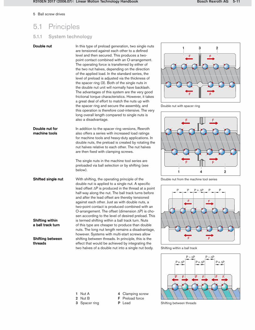
5-11Bosch Rexroth AG
PP PP + !P P
FF FF
FF FF
P + !P P + !PP – !P P – !P
P + !P
FF FF FF FF FF FF
1 23
41 2
5 Ball screw drives
Linear Motion Technology HandbookR310EN 2017 (2006.07)
5.1 Principles5.1.1 System technology
In this type of preload generation, two single nuts are tensioned against each other to a defined level and then secured. This produces a two-point contact combined with an O-arrangement. The operating force is transferred by either of the two nut halves, depending on the direction of the applied load. In the standard series, the level of preload is adjusted via the thickness of the spacer ring (3). Both of the single nuts in the double nut unit will normally have backlash. The advantages of this system are the very good frictional torque characteristics. However, it takes a great deal of effort to match the nuts up with the spacer ring and secure the assembly, and this operation is therefore cost-intensive. The very long overall length compared to single nuts is also a disadvantage.
Double nutDouble nut
Double nut with spacer ring
Double nut from the machine tool series
In addition to the spacer ring versions, Rexroth also offers a series with increased load ratings for machine tools and heavy-duty applications. In double nuts, the preload is created by rotating the nut halves relative to each other. The nut halves are then fixed with clamping screws.
The single nuts in the machine tool series are preloaded via ball selection or by shifting (see below).
Double nut for machine toolsDouble nut for machine tools
Shifting within a ball track
Shifting between threads
With shifting, the operating principle of the double nut is applied to a single nut. A specific lead offset P is produced in the thread at a point half-way along the nut. The ball track turns before and after the lead offset are thereby tensioned against each other. Just as with double nuts, a two-point contact is produced combined with an O-arrangement. The offset (dimension P) is cho-sen according to the level of desired preload. This is termed shifting within a ball track turn. Nuts of this type are cheaper to produce than double nuts. The long nut length remains a disadvantage, however. Systems with multi-start screws allow shifting between threads. In principle, this is the effect that would be achieved by integrating the two halves of a double nut into a single nut body.
Shifted single nutShifted single nut
Shifting within a ball track turnShifting within a ball track turn
Shifting between threadsShifting between threads
Nut ANut BSpacer ring
1�2�3�
Clamping screwF Preload force P Lead
4�

5-12 Bosch Rexroth AG
1Rtot
1RaL
1RS
1Rnu
= + +
5 Ball screw drives
Linear Motion Technology Handbook R310EN 2017 (2006.07)
5.1 Principles5.1.1 System technology
5.1.1.4 Rigidity
The rigidity of a ball screw assembly is influenced not only by the ball nut’s rigidity but also by all the adjoining parts such as bearings, housing bores, nut housings, etc.
The overall axial rigidity Rtot is comprised of the component rigidity of the bearing RaL, the screw RS and the nut Rnu .
Rigidity of a ball screw assemblyRigidity of a ball screw assembly
Definition of the overall axial rigidity Rtot
Definition of the overall axial rigidity Rtot
Rtot = overall axial rigidity (N/m)RaL = rigidity of the bearing (N/m)RS = rigidity of the screw (N/m)Rnu = rigidity of the nut unit (N/m)
The component with the lowest rigidity is there-fore the determining factor for the ball screw assembly’s overall axial rigidity Rtot . In many cases, the rigidity RS of the screw will be signifi-cantly lower than the rigidity Rnu of the nut unit.
In an assembly of size 40 x 10 (d0 . P), for exam-ple, the rigidity Rnu of the nut unit will be two or three times higher than the rigidity RS of a screw with a length of 500 mm.
The rigidity of the bearing corresponds to the value provided by the bearing manufacturer. Details of the rigidities of Rexroth bearings are shown in the ball screw product catalogs.
Rigidity of the bearing RaL
Rigidity of the bearing RaL
The rigidity in the area of the preloaded nut unit is calculated according to DIN 69051 Part 5. Details of the rigidities of the nut units are also given in the product catalogs.
Rigidity of the nut unit Rnu
Rigidity of the nut unit Rnu
Rigidity is understood as being the resistance to elastic deformation. The rigidity R denotes the force required to produce a certain deformation in the direction of loading.
Definition of rigidityDefinition of rigidity
(5-1)
R = rigidity (N/m)F = change in force (N)l = elastic deformation (m)
(5-2)
The rigidity of the screw depends on the screw’s cross-sectional area, the screw length, the posi-tion of the nut unit on the screw and the type of bearing used. The rigidity of the screw is calculat-ed according to DIN 69051 Part 6. The following two installation examples illustrate the method for
calculating the screw rigidity. The product cata-logs contain corresponding tables which can be used to compare the screw and nut rigidities at the pre-selection stage. The screw rigidity details relate to a screw length of 1 meter.
Rigidity of the screw RS
Rigidity of the screw RS
!
!

5-13Bosch Rexroth AG
lS1lS2
lS
RS2 = ·! · ( d0 – DW · cos ") · E
4 · lS2 · 103
2 Nµm
lS lS – lS2
RS1 =! · ( d0 – DW · cos ") · E
4 · lS1 · 103
2 Nµm
5 Ball screw drives
Linear Motion Technology HandbookR310EN 2017 (2006.07)
5.1 Principles5.1.1 System technology
Example 1: Ball screw shaft fixed at one end Example 2: Ball screw shaft fixed at both ends
RS1 = rigidity of screw with shaft fixed at one end (N/m)
RS2 = rigidity of screw with shaft fixed at both ends (N/m)
E = elasticity modulus (N/mm2) d0 = nominal diameter (mm)DW = ball diameter (mm)
The complete formula for calculating the screw rigidity RS2 is:
By inserting the values for the material (E = 210,000 N/mm2) and the ball track geom-etry ( = 45°) and combining the dimensionless values we obtain the following simplified formula:
(5-5)
The simplified formula for calculating the screw rigidity RS2 is:
The lowest screw rigidity RS2min occurs at the centre of the screw (lS2 = lS/2) and thus equals:
The complete formula for calculating the screw rigidity RS1 is:
(5-3)
lS1 = distance between bearing and nut (mm)lS2 = distance between bearing and nut (mm)lS = distance between bearing and bearing (mm) = contact angle between the ball and
the raceway (°)
RS1 = 165 · (d0 – 0.71 · DW)
lS1
2 Nµm RS2 = 165 · ·
(d0 – 0.71 · DW)lS2
lS lS – lS2
2 Nµm
RS2min = 660 · (d0 – 0.71 · DW)
lS
2 Nµm
(5-4) (5-6)
(5-7)

5-14 Bosch Rexroth AG
5 Ball screw drives
Linear Motion Technology Handbook R310EN 2017 (2006.07)
5.1 Principles5.1.1 System technology
5.1.1.5 Accuracy
DIN 69051 Part 3 (ISO 3408-3) defines the acceptance conditions and the acceptance tests for ball screw assemblies. Different tolerance grades are specified, with a distinction being made between positioning drives and transport drives.
StandardStandard The most important terms, tolerances and tests are explained in the following paragraphs:
Travel deviations and variationsRun-outs and location deviationsDrag torque variations
Even with the most advanced production tech-niques, it is impossible to produce a ball screw with no deviations. The amount of travel deviation is evaluated according to a series of tolerance
Travel deviations and variationsTravel deviations and variations
grades. The evaluation is performed in three steps that are explained below, with reference to the chart on the opposite page.
If required, a target value for the travel deviation is determined before beginning the actual evaluation process. This target travel deviation, known as the travel compensation c, is the desired deviation
Travel compensation Travel compensation from the nominal lead within the useful travel. It is determined by the user and depends on the con-ditions of use and the specific application. The standard value for travel compensation is zero.
A second evaluation step is performed for a reference length of 300 mm. In this case, the value 300p for the specified tolerance grade may not be exceeded at any point on the screw within the 300mm length.The tolerance for travel variations within 300 mm of travel is verified for positioning ball screws and for transport ball screws.
Evaluation over a reference lengthEvaluation over a reference length
Tolerance grade1 3 5 7 9
300p (m) 6 12 23 52 130
Extract from the ball screws catalog: values for 300p according to the tolerance grade
The travel deviation is evaluated first of all over the entire useful length. The actual travel deviation is recorded over the useful travel lu . Since the actual travel deviation is difficult to evaluate, the mean actual travel devia-tion is determined as the geometric mean of the measurements recorded over the useful travel. The difference between the travel compensation value and the mean actual travel deviation at the end of the useful travel constitutes the tolerance for mean actual travel deviation ep, which gives an indication of the screw’s average precision over the useful travel lu . However, a screw might exhibit widely varying accuracy errors that virtually canceled each other out over the useful travel. The tolerance for mean actual travel deviation ep would then indicate a high level of precision, even
Evaluation over the entire useful lengthEvaluation over the entire useful length
though the screw displayed significant errors. For this reason, the bandwidth of travel variation around the mean actual travel deviation must also be analyzed. To do this, two lines are drawn parallel to the line for mean actual travel devia-tion to form an “envelope” enclosing the actual travel deviation curve. The distance between these parallel lines is called the permissible travel variation within the useful travel and is denoted by the symbol up . This is the bandwidth for travel variations.
The ep value is verified for both positioning ball screws and transport ball screws. For positioning ball screws, the up valve is verified in addition. The figures for these values can be found in the product catalogs.
Extract from the ball screws catalog: values for ep and up according to the useful travel and the tolerance grade
lu ep (µm) tolerance grade up (m) tolerance grade
1 3 5 7 9 1 3 5400 500 8 15 27 63 200 7 13 26500 630 9 16 30 70 220 7 14 29

5-15Bosch Rexroth AG
!
"
"
#
#
""
5 Ball screw drives
Linear Motion Technology HandbookR310EN 2017 (2006.07)
The third step is to evaluate the travel deviation per revolution. This value is called the permissible travel deviation within one revolution (2 rad) and is denoted by the symbol 2 p.This check is only performed for positioning ball screws (precision ball screws).
Evaluation per revolutionEvaluation per revolution
Tolerance grade1 3 5 7 9
2 p (m) 4 6 8 10 10
Extract from the ball screws catalog: values for 2 p according to the tolerance grade
5.1 Principles5.1.1 System technology
Sample chart for evaluating travel deviations and variations in ball screw assemblies
– Travel compensation (target travel deviation)– Actual travel deviation – Mean actual travel deviation- - Permissible travel variation (tolerance “envelope”)I0 = nominal travelI1 = thread lengthI0 = travel deviationIe = excess travel (non-usable length)Iu = useful travel
c = travel compensation for useful travel (standard: c = 0)
ep = tolerance for mean actual travel deviationup = permissible travel variation within useful
travel Iu300p = permissible travel deviation within
300 mm travel2 p = permissible travel deviation within
one revolution (2 rad)
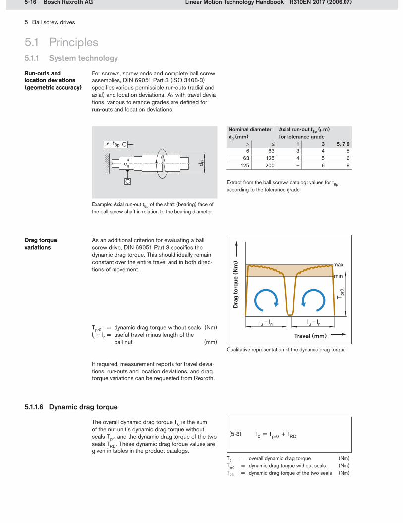
5-16 Bosch Rexroth AG
d 0d
C
Ct8p
lu – ln lu – ln
T pr0
min
max
5 Ball screw drives
Linear Motion Technology Handbook R310EN 2017 (2006.07)
5.1 Principles5.1.1 System technology
For screws, screw ends and complete ball screw assemblies, DIN 69051 Part 3 (ISO 3408-3) specifies various permissible run-outs (radial and axial) and location deviations. As with travel devia-tions, various tolerance grades are defined for run-outs and location deviations.
Run-outs and location deviations (geometric accuracy)
Run-outs and location deviations (geometric accuracy)
Example: Axial run-out t8p of the shaft (bearing) face of the ball screw shaft in relation to the bearing diameter
Nominal diameter d0 (mm)
Axial run-out t8p (m) for tolerance grade
1 3 5, 7, 96 63 3 4 5
63 125 4 5 6125 200 – 6 8
As an additional criterion for evaluating a ball screw drive, DIN 69051 Part 3 specifies the dynamic drag torque. This should ideally remain constant over the entire travel and in both direc-tions of movement.
Drag torque variationsDrag torque variations
Qualitative representation of the dynamic drag torque
(5-8)
Tpr0 = dynamic drag torque without seals (Nm)lu – ln = useful travel minus length of the
ball nut (mm)
Extract from the ball screws catalog: values for t8p according to the tolerance grade
5.1.1.6 Dynamic drag torque
Dra
g to
rque
(N
m)
Travel (mm)
If required, measurement reports for travel devia-tions, run-outs and location deviations, and drag torque variations can be requested from Rexroth.
The overall dynamic drag torque T0 is the sum of the nut unit’s dynamic drag torque without seals Tpr0 and the dynamic drag torque of the two seals TRD . These dynamic drag torque values are given in tables in the product catalogs.
T0 = overall dynamic drag torque (Nm)Tpr0 = dynamic drag torque without seals (Nm)TRD = dynamic drag torque of the two seals (Nm)

5-17Bosch Rexroth AG
!
vmax = = (d0 · n) · P
d0
mmmin150000 · P
d0
5 Ball screw drives
Linear Motion Technology HandbookR310EN 2017 (2006.07)
5.1 Principles5.1.1 System technology
5.1.1.7 Characteristic speed and maximum linear speed
Rexroth ball screws can be operated at very high speeds due to their internal ball recircula-tion system. Characteristic speeds of up to 150,000 mm/min are possible, depending on the nut type. The theoretically possible maximum linear speed vmax can be calculated from the char-acteristic speed and the screw lead P. The values for vmax can be found in the product catalogs.
d0 · n = characteristic speed (mm/min) d0 = nominal screw diameter (mm)n = rotary speed (min-1)vmax = theoretical maximum linear speed (mm/min)P = lead (mm)
5.1.1.8 Mechanical efficiency
Due to the use of rolling elements, sliding friction is largely avoided (with the exception of con-tact seals, for example). Ball screw assemblies therefore have a very high degree of mechanical
efficiency. As a result, they can be put to very effective use as powerful machine components for a wide variety of applications.
Comparison: Efficiency of ball screw assemblies versus that of acme screws
– Ball screw assembly with two-point contact– Ball screw assembly with four-point contact– Acme screw = friction coefficient
In practice, the actually attainable linear speeds will depend heavily on factors such as the preload and the duty cycle. They are generally restricted by the critical screw speed, see section 5.1.3.3.
(5-9)
100
90
80
70
60
50
40
30
20
10
0 1 2 3 4 5 6 7 8 90
µ = 0.005
µ = 0.01
µ = 0.3
µ = 0.2
Effic
ienc
y (%
)
Lead angle (°)

5-18 Bosch Rexroth AG
1
1
5 Ball screw drives
Linear Motion Technology Handbook R310EN 2017 (2006.07)
5.1 Principles5.1.1 System technology
5.1.1.9 Lubrication
Just like every other type of rolling bearing, ball screws must be adequately lubricated. They can be lubricated with oil or grease. Normally, the ball nut is lubricated via a lube port (1). In the case of flanged nuts, the lube port is situated on the flange. The lubricant quantities depend on the size of the ball nut. The in-service lubrication inter-vals depend on the lead and the loads applied. All the relevant lubrication details are provided in the Rexroth product catalogs.
During a very short stroke, the balls do not make complete turns and the lubricant is not distributed optimally in the nut. This can result in premature wear. To avoid this, occasional longer strokes should be performed, which can also be designed as lubricating strokes for simultaneous in-service lubrication.
Lube port Lube port
Short strokeShort stroke
Flanged ball nut
Cylindrical ball nut

5-19Bosch Rexroth AG
5 Ball screw drives
Linear Motion Technology HandbookR310EN 2017 (2006.07)
5.1 Principles5.1.2 Product selection
5.1.2.1 Guide to choosing the right product
Ball nut type Load-carrying capability Rigidity Accuracy Friction
Single nut, Standard series +++ +++ +++ ++
Adjustable nut, Standard series +++ +++ +++ ++
Single nut, Speed series ++ + ++ ++
Single nut, eLINE series + + + ++
Single nut, Miniature series + + ++ ++
Double nut
+++ +++ +++ +++
Ball nut type Speed Noise characteristics1) Lubrication requirement Costs
Single nut, Standard series ++ ++ ++ ++
Adjustable nut, Standard series ++ ++ ++ ++
Single nut, Speed series +++ +++ ++ ++
Single nut, eLINE series + + ++ +++
Single nut, Miniature series + ++ +++ ++
Double nut
++ ++ + +
+++ Very good ++ Good + Satisfactory o Adequate
System characteristics
at the same linear speed1)
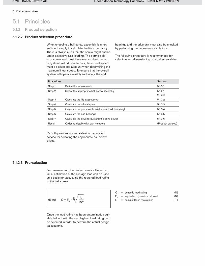
5-20 Bosch Rexroth AG
C = Fm ·L
1063
5 Ball screw drives
Linear Motion Technology Handbook R310EN 2017 (2006.07)
5.1.2.3 Pre-selection
5.1 Principles5.1.2 Product selection
For pre-selection, the desired service life and an initial estimation of the average load can be used as a basis for calculating the required load rating of the ball screw.
(5-10)
C = dynamic load rating (N)Fm = equivalent dynamic axial load (N)L = nominal life in revolutions (–)
Once the load rating has been determined, a suit-able ball nut with the next highest load rating can be selected in order to perform the actual design calculations.
5.1.2.2 Product selection procedure
When choosing a ball screw assembly, it is not sufficient simply to calculate the life expectancy. There is always a risk that the screw might buckle under excessive axial loading. The permissible axial screw load must therefore also be checked. In systems with driven screws, the critical speed must be taken into account when determining the maximum linear speed. To ensure that the overall system will operate reliably and safely, the end
Rexroth provides a special design calculation service for selecting the appropriate ball screw drives.
Procedure Section
Step 1 Define the requirements 5.1.3.1
Step 2 Select the appropriate ball screw assembly 5.1.2.15.1.2.3
Step 3 Calculate the life expectancy 5.1.3.2
Step 4 Calculate the critical speed 5.1.3.3
Step 5 Calculate the permissible axial screw load (buckling) 5.1.3.4
Step 6 Calculate the end bearings 5.1.3.5
Step 7 Calculate the drive torque and the drive power 5.1.3.6
Result Ordering details with part numbers (Product catalog)
bearings and the drive unit must also be checked by performing the necessary calculations.
The following procedure is recommended for selection and dimensioning of a ball screw drive.
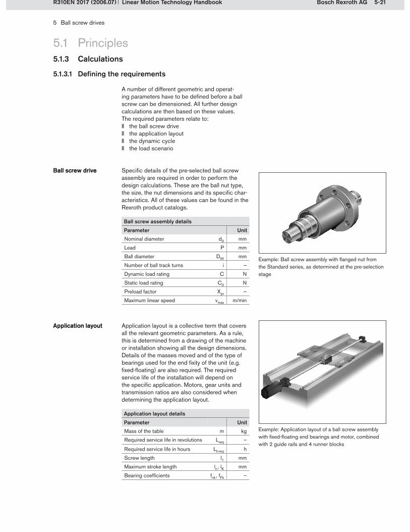
5-21Bosch Rexroth AG
5 Ball screw drives
Linear Motion Technology HandbookR310EN 2017 (2006.07)
5.1 Principles5.1.3 Calculations
5.1.3.1 Defining the requirements
A number of different geometric and operat-ing parameters have to be defined before a ball screw can be dimensioned. All further design calculations are then based on these values. The required parameters relate to:
the ball screw drivethe application layoutthe dynamic cyclethe load scenario
Specific details of the pre-selected ball screw assembly are required in order to perform the design calculations. These are the ball nut type, the size, the nut dimensions and its specific char-acteristics. All of these values can be found in the Rexroth product catalogs.
Ball screw driveBall screw drive
Example: Ball screw assembly with flanged nut from the Standard series, as determined at the pre-selection stage
Application layout is a collective term that covers all the relevant geometric parameters. As a rule, this is determined from a drawing of the machine or installation showing all the design dimensions. Details of the masses moved and of the type of bearings used for the end fixity of the unit (e.g. fixed-floating) are also required. The required service life of the installation will depend on the specific application. Motors, gear units and transmission ratios are also considered when determining the application layout.
Application layoutApplication layout
Example: Application layout of a ball screw assembly with fixed-floating end bearings and motor, combined with 2 guide rails and 4 runner blocks
Ball screw assembly details
Parameter UnitNominal diameter d0 mm
Lead P mm
Ball diameter DW mm
Number of ball track turns i –
Dynamic load rating C N
Static load rating C0 N
Preload factor Xpr –
Maximum linear speed vmax m/min
Application layout details
Parameter UnitMass of the table m kg
Required service life in revolutions Lreq –
Required service life in hours Lh req h
Screw length l1 mm
Maximum stroke length ln , lK mm
Bearing coefficients fnk , fFk –

5-22 Bosch Rexroth AG
FgFgFaFa
FRFR
FRFRFRFR
FRFR
FRFR
FpFp
t4
t5
t6
n6v6n6v6
n5v5n5v5
n4v4n4v4
2
1
5 Ball screw drives
Linear Motion Technology Handbook R310EN 2017 (2006.07)
5.1 Principles5.1.3 Calculations
The next step is to determine a reference cycle for the application. This cycle represents the expected dynamic motion sequences and forms the basis for calculating the nominal life. Cycles consist of several phases representing the individ-ual operating steps that the ball screw drive is to perform (e.g. acceleration, braking, processing/machining, etc.). The time, travel, linear speed, ac-celeration and rotary speed must be determined for each phase. The ball screw drive’s duty cycle is required for calculating the life expectancy of the ball screw drive in the specific machine or installation.
Dynamic cycleDynamic cycle
Example of a simple dynamic cycle
Travel-time curveSpeed-time curve
1�2�
A ball screw drive can only take up forces act- ing in the axial direction. All other loads must be carried by the guide units. Depending on the application, the axial forces may include weight forces Fg , acceleration forces Fa , process forces Fp , and friction forces FR .
Load scenarioLoad scenario
Example showing an axially effective process force Fp
Dynamic cycle detailsParameter UnitPhase n –Time for phase 1 … n t1 … tn sTravel in phase 1 … n s1 … sn mmLinear speed in phase 1 … n v1 … vn m/sAcceleration in phase 1 … n a1 … an m/s2
Rotary speed in phase 1 … n n1 … nn min–1
Duty cycle of the machine DCmachine %Duty cycle of the ball screw drive DCBS %
Example of a simple dynamic cycle: return strokeExample of a simple dynamic cycle: forward stroke
v (m
/s)
0.6
0.4
0.2
0
- 0.2
- 0.4
- 0.60 1 2 3 4 5 6 7 8
t (s)
t1 t2 t3 t4 t5 t6
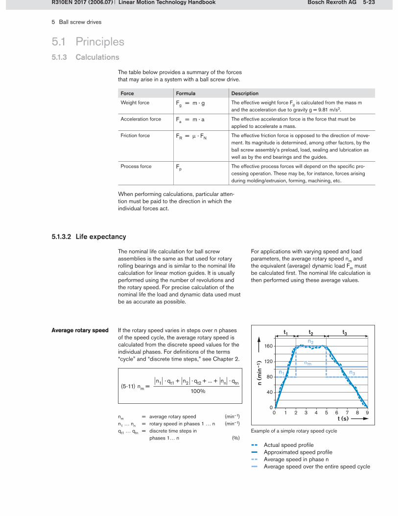
5-23Bosch Rexroth AG
n (m
in–1
)
t (s)
t1n2
n3n1
nm
t2 t3
5 Ball screw drives
Linear Motion Technology HandbookR310EN 2017 (2006.07)
5.1 Principles5.1.3 Calculations
Force Formula Description
Weight force Fg = m · g The effective weight force Fg is calculated from the mass m and the acceleration due to gravity g = 9.81 m/s2.
Acceleration force Fa = m · a The effective acceleration force is the force that must be applied to accelerate a mass.
Friction force FR = · FN The effective friction force is opposed to the direction of move-ment. Its magnitude is determined, among other factors, by the ball screw assembly’s preload, load, sealing and lubrication as well as by the end bearings and the guides.
Process force Fp The effective process forces will depend on the specific pro-cessing operation. These may be, for instance, forces arising during molding/extrusion, forming, machining, etc.
When performing calculations, particular atten-tion must be paid to the direction in which the individual forces act.
5.1.3.2 Life expectancy
The nominal life calculation for ball screw assemblies is the same as that used for rotary rolling bearings and is similar to the nominal life calculation for linear motion guides. It is usually performed using the number of revolutions and the rotary speed. For precise calculation of the nominal life the load and dynamic data used must be as accurate as possible.
If the rotary speed varies in steps over n phases of the speed cycle, the average rotary speed is calculated from the discrete speed values for the individual phases. For definitions of the terms “cycle” and “discrete time steps,” see Chapter 2.
Average rotary speed Average rotary speed
(5-11)
nm = average rotary speed (min–1)n1 … nn = rotary speed in phases 1 … n (min–1)qt1 … qtn = discrete time steps in
phases 1… n (%)Example of a simple rotary speed cycle
For applications with varying speed and load parameters, the average rotary speed nm and the equivalent (average) dynamic load Fm must be calculated first. The nominal life calculation is then performed using these average values.
The table below provides a summary of the forces that may arise in a system with a ball screw drive.
-- Actual speed profile– Approximated speed profile-- Average speed in phase n– Average speed over the entire speed cycle
nm =n1 · qt1 + n2 · qt2 + ... + nn · qtn
100%
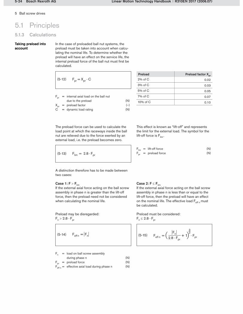
5-24 Bosch Rexroth AG
5 Ball screw drives
Linear Motion Technology Handbook R310EN 2017 (2006.07)
5.1 Principles5.1.3 Calculations
The preload force can be used to calculate the load point at which the raceways inside the ball nut are relieved due to the force exerted by an external load, i.e. the preload becomes zero.
This effect is known as “lift-off” and represents the limit for the external load. The symbol for the lift-off force is Flim .
(5-13)Flim = lift-off force (N)Fpr = preload force (N)
A distinction therefore has to be made between two cases:
Case 1: F FlimIf the external axial force acting on the ball screw assembly in phase n is greater than the lift-off force, then the preload need not be considered when calculating the nominal life.
Case 2: F FlimIf the external axial force acting on the ball screw assembly in phase n is less than or equal to the lift-off force, then the preload will have an effect on the nominal life. The effective load Feff n must be calculated.
(5-14)
Preload may be disregarded:Fn 2.8 · Fpr
Preload must be considered:Fn 2.8 · Fpr
(5-15)
Fn = load on ball screw assembly during phase n (N)
Fpr = preload force (N)Feff n = effective axial load during phase n (N)
In the case of preloaded ball nut systems, the preload must be taken into account when calcu-lating the nominal life. To determine whether the preload will have an effect on the service life, the internal preload force of the ball nut must first be calculated.
Taking preload into account Taking preload into account
(5-12)Preload Preload factor Xpr
2% of C 0.02
3% of C 0.03
5% of C 0.05
7% of C 0.07
10% of C 0.10
Fpr = internal axial load on the ball nut due to the preload (N)
Xpr = preload factor (–)C = dynamic load rating (N)
Flim = 2.8 · Fpr
Feff n = + 1 · Fpr Fn
2.8 · Fpr
32

5-25Bosch Rexroth AG
F (N
)
t (s)
t1 t2
Feff 1
Feff 2 Feff 3
Fm
t3
5 Ball screw drives
Linear Motion Technology HandbookR310EN 2017 (2006.07)
5.1 Principles5.1.3 Calculations
If the load on the ball screw assembly varies in steps, the average axial load must be determined before performing the nominal life calculation. The equivalent dynamic axial load Fm is obtained from the individual loads Fn during the phases n.
Equivalent dynamic axial loadEquivalent dynamic axial load
Equivalent dynamic axial load at constant speed:
(5-16)
Equivalent dynamic axial load at varying speed:
(5-17)
Fm = equivalent dynamic axial load (N)Feff 1 … Feff n = effective load during
phases 1 … n (N)nm = average speed (min–1)n1 … nn = speed during phases 1 … n (min–1)qt1 … qtn = discrete time steps for
phases 1 … n (%)
Example of a simple load cycle at constant rotary speed
-- Actual force profile– Approximated force profile– Equivalent dynamic load
Fm = Feff 1 · + Feff 2 · + ... + Feff n · 3 qtn
100%qt2
100%qt1
100%
3 3 3
Fm = Feff 1 · · + Feff 2 · · + ... + Feff n · · 3 n1
nm
n2nm
nnnm
3 3 3 qtn100%
qt2100%
qt1100%
5-26 Bosch Rexroth AG
L = · 106CFm
3
5 Ball screw drives
Linear Motion Technology Handbook R310EN 2017 (2006.07)
5.1 Principles5.1.3 Calculations
Since the required service life of the machine is generally also specified, the life of the ball screw must be recalculated in terms of the duty cycle.
(5-20)
Machine operating hours Machine operating hours
The nominal life is expressed by the number of revolutions or number of operating hours at con-stant speed that will be attained or exceeded by 90% of a representative sample of identical ball screws before the first signs of material fatigue become evident.
The nominal life in revolutions is designated as L and is calculated using the following formula:
Nominal lifeNominal life
(5-18)
Nominal life in revolutionsNominal life in revolutions
L = nominal life in revolutions (–)C = dynamic load rating (N)Fm = equivalent dynamic axial load
on the ball screw (N)
(5-19)
Nominal life in hoursNominal life in hours
Lh = nominal life in hours (h)L = nominal life in revolutions (–)nm = average speed (min–1)
Lh machine = nominal machine service life in hours (h)
Lh = nominal ball screw service life in hours (h)
DCmachine = machine duty cycle (%)DCBS = ball screw duty cycle (%)
The nominal life in hours Lh is calculated from the average rotary speed:
Lh machine = Lh · DCmachine
DCBS

5-27Bosch Rexroth AG
5 Ball screw drives
Linear Motion Technology HandbookR310EN 2017 (2006.07)
5.1 Principles5.1.3 Calculations
5.1.3.3 Critical speed
The rotation of the screw causes bending vibra-tions (also known as screw whip). The frequency of these vibrations is the screw’s rotation fre-quency. The “critical speed” is the rotary speed that is equivalent to the first order frequency of the screw. If the ball screw assembly is operated at the critical speed, resonance occurs, which can lead to destruction of the system. To avoid this, the critical speed must be determined when performing the design calculations for the ball screw.
The critical speed nk depends on:the type of end bearings, coefficient fnkthe screw’s core diameter d2the critical screw length ln , i.e. the maximum unsupported screw length. In the case of ball nuts with backlash, the criti-cal screw length is the same as the bearing-to-bearing length l1. In preloaded systems, the position of the ball nut is taken into account.
The product catalog contains charts for quickly checking the calculation results. When dimen-sioning and selecting ball screw drives, the operating speed should never be more than 80% of the critical speed. The characteristic speed and the maximum permissible linear speed must not be exceeded.
Critical speed nkCritical speed nk
nk = critical speed (min–1)nk perm = permissible operating speed (min–1)fnk = coefficient as a function of the
end bearings (–)d2 = screw core diameter
(see product catalog) (mm)l1 = bearing-to-bearing distance (mm)ln = critical screw length for preloaded
nut systems (mm) (For nuts with backlash: ln = l1)
The following measures can be taken to ensure that the screw speed remains outside the critical speed range:
Increase the screw diameter.Choose appropriate end bearings.Use preloaded ball nuts instead of nuts with backlash.Use screw supports (see section 5.3.1.1).
Rexroth also offers drive units with driven nuts. When using driven nuts, less energy is introduced into the vibratory system because eccentricities within the rotating system are avoided and good axial and radial run-out is maintained. If resonance should occur, the lower energy input ensures that the consequences will be far less destructive for an optimized system with driven nut than they would be for a system with a rotating screw. For drive units with driven nut, see section 5.3.2.
Driven nutsDriven nuts
Bending vibrations (screw whip)
End fixity Coefficient fnk
l1
ln
27.4
l1
ln
18.9
l1
ln
12.1
l1
ln
4.3
fixed-fixed
fixed-floating
floating-floating
fixed-free
(5-21)
(5-22) nk perm = nk · 0.8

5-28 Bosch Rexroth AG
Fk = fFk · · 104d2 lk
4
2 (N)
5 Ball screw drives
Linear Motion Technology Handbook R310EN 2017 (2006.07)
5.1 Principles5.1.3 Calculations
5.1.3.4 Permissible axial load on screw (buckling load)
Buckling stress is a special instance of compres-sive stress. If a rod (in this case, the screw shaft) is subjected to a compressive force in the axial direction, it will begin to bend in the shape of a bow. The change in shape increases rapidly with increasing load.
Axial loads occur in ball screw drives as a result of acceleration, friction and weight and process forces. The resultant stress depends on:
the end bearings, coefficient fFkthe screw’s core diameter d2the effective buckling length lk of the screw, i.e. the maximum unsupported screw length in the direction of the force’s flow between the ball nut and the end bearing.
The permissible axial screw load Fk can be calcu-lated from these variables. Just as for the critical speed, the product catalog contains charts allow-ing a quick cross-check on the buckling load.When dimensioning and selecting ball screw drives, a buckling safety factor of at least 2 should be used when calculating the permissible axial load.
BucklingBuckling
(5-23)
Permissible axial screw load Fk
Permissible axial screw load Fk
Fk = theoretical buckling load of the screw (N)Fk perm = permissible axial load on the screw
in service (N)fFk = coefficient as a function of the
end bearings (–)d2 = screw core diameter
(see product catalog) (mm)lk = effective buckling length of the screw (mm)
The following measures can be taken to avoid buckling:
Increase the screw diameter.Choose appropriate end bearings.
Buckling caused by axial loading
(5-24)
End fixity Coefficient fFk
FF FF
lk
40.6
FF FF
lk
20.4
FF FF
lk
10.2
FF FF
lk
2.6
fixed-fixed
fixed-floating
floating-floating
fixed-free
Fk perm = Fk 2

5-29Bosch Rexroth AG
Mta = F · P
2000 · ! · "(Nm)
Pa = Mta · n9550
(kW)
F
Mta
n v
Mte
F
n
Mte = F · P · !´2000 · "
(Nm)
5 Ball screw drives
Linear Motion Technology HandbookR310EN 2017 (2006.07)
5.1 Principles5.1.3 Calculations
5.1.3.5 End bearings
The end bearings are calculated using the values determined for the rotary speed and the loads on the ball screw assembly. The nominal life must be calculated in accordance with the manufacturer’s specifications for the particular type of bearing used.
5.1.3.6 Drive torque and drive power
The following formulas can be used for an initial estimation of the required drive torque and power.
The calculation method and the corresponding formulas for calculating the bearings used by Rexroth are given in the product catalog.
(5-25)
Mta = drive torque (Nm)Mte = transmitted torque (Nm)F = operating load (N)P = lead (mm)
mechanical efficiency (–) 0.9 for drive torque ´0.8 for transmitted torque
(5-27)
Drive powerDrive power Pa = drive power (kW)Mta = drive torque (Nm)n = rotary speed (min-1)
This calculation serves merely to arrive at an initial estimation, since it takes only the ball screw into account. For precise calculation, additional influ-encing factors such as the guide units, the end bearings, mass moments of inertia and dynamic drag torques must also be taken into account. The overall dynamic drag torque T0 is the sum of the dynamic drag torque of the preloaded nut Tpr0 and the dynamic drag torque of the two seals TRD (see section 5.1.1.6).
Details of Tpr0 and TRD are given in the product catalogs. Precise configuration and calculation of the drive unit should ideally be done in collabo-ration with a motor and controller manufacturer. A check must also be made to determine whether the screw ends are strong enough to transfer the drive torque. Details of the screw ends can also be found in the product catalogs.
(5-26)
Drive torque Mta :An applied drive torque Mta causes the screw to rotate. As a reaction to the screw’s rotation, a linear force F is generated in the ball nut, which causes linear motion of the nut.
Definitions of drive torque and transmitted torque
Definitions of drive torque and transmitted torque
Transmitted torque Mte :The screw moves under the action of a thrust force F in the axial direction. As a reaction, a transmitted torque Mte is generated, causing the nut to rotate, provided there is no self-locking effect due to the lead angle.
Conversion of rotary to linear motion Conversion of linear to rotary motion

5-30 Bosch Rexroth AG
600
20018020
800
980
Ø40
5 Ball screw drives
Linear Motion Technology Handbook R310EN 2017 (2006.07)
5.1 Principles5.1.3 Calculations
5.1.3.7 Calculation example
A ball screw drive is to be used for the feed motion in the drilling station of a transfer line. Positioning is controlled using a glass measuring scale.
The following example illustrates the complete procedure for calculating the ball screw drive.
Calculation example for a drilling station
Weight of the carriage including attachments m1 = 400 kgThe carriage is guided by 4 roller runner blocks on 2 guide railsTotal force required to move the carriage FR = 150 NThe maximum axial load is the process force during drilling Fp = 4500 NEnd fixity of the screw: fixed-floatingUnsupported screw length: 800 mmMaximum linear speed vmax = 0.5 m/s at nmax = 3000 min–1
Drive using a servo-motor via a timing belt with a transmission ratio of i = 0.5The required service life for the complete drilling station is at least 6 years operating 360 days a year in 3 shifts. Lh machine = 6 a · 360 d/a · 24 h/d Lh machine = 51840 h
Technical data of the applicationTechnical data of the application
During pre-selection, a ball screw assembly size 40 x 20 (d0 x P) with a preload of 5% of C was chosen.
Ball screw assemblyBall screw assembly
Drilling station
Dimensions for calculating the ball screw drive

5-31Bosch Rexroth AG
5 Ball screw drives
Linear Motion Technology HandbookR310EN 2017 (2006.07)
5.1 Principles5.1.3 Calculations
A reference cycle is defined for calculating the ball screw assembly. In this reference cycle, a bore is drilled during phase 2 of the forward stroke. This is followed by a fast return stroke (phases 4 to 6). The complete cycle is executed in 3 seconds. After the reference cycle the work-piece is changed, which also takes 3 seconds. This results in a duty cycle for the ball screw drive of 50% of the machine duty cycle, which must be taken into account in the machine’s service life.
Dynamic cycleDynamic cycle
Reference cycle
Phase n
Travel coor-dinates sx
Travel sn Linear speed vn
Time tn Acceleration an
Rotary speed values |n|
Average rotary speed |nn|
Description
1 0 mm 20 mm 0 m/s 0.4 s 0.25 m/s2 0 min–1 150 min–1 Acceleration20 mm 0.1 m/s 300 min–1
2 20 mm 160 mm 0.1 m/s 1.6 s 0 m/s2 300 min–1 300 min–1 Constant motionDrilling180 mm 0.1 m/s 300 min–1
3 180 mm 20 mm 0.1 m/s 0.4 s –0.25 m/s2 300 min–1 150 min–1 Deceleration200 mm 0 m/s 0 min–1
4 200 mm –50 mm 0 m/s 0.2 s –2.5 m/s2 0 min–1 750 min–1 AccelerationReturn stroke150 mm –0.5 m/s 1500 min–1
5 150 mm –100 mm –0.5 m/s 0.2 s 0 m/s2 1500 min–1 1500 min–1 Constant motionReturn stroke50 mm –0.5 m/s 1500 min–1
6 50 mm –50 mm –0.5 m/s 0.2 s 2.5 m/s2 1500 min–1 750 min–1 Deceleration Return stroke0 mm 0 m/s 0 min–1
Only constant operating parameters for each phase are used in the nominal life calculation. Therefore, the average rotary speed nm must be determined for the phases with acceleration or deceleration.
The curves below show the profiles for all the relevant kinematic parameters (travel sn , linear speed vn , acceleration an and rotary speed |nn|) over the reference cycle.
Kinematic data for the reference cycle
1 2 3
6 5 4
0.20.1
0– 0.1– 0.2– 0.3– 0.4– 0.5– 0.6
0 50 100 150 200 250
v (m
/s)
s (mm)
s (m
m)
t (s)
25020015010050
0– 50
3210
– 1– 2– 3
0.2
0
– 0.2
– 0.4
– 0.6
1600
1200
800
400
0
0 1 2 3 3.50.5 1.5 2.5
a (m
/s2 )
t (s)0 1 2 3 3.50.5 1.5 2.5
v (m
/s)
t (s)0 1 2 3 3.50.5 1.5 2.5
n (
min
–1)
t (s)0 1 2 3 3.50.5 1.5 2.5

5-32 Bosch Rexroth AG
5 Ball screw drives
Linear Motion Technology Handbook R310EN 2017 (2006.07)
5.1 Principles5.1.3 Calculations
The discrete time steps are required for determin-ing the average rotary speeds and the loads.
Discrete time stepsDiscrete time steps
The dynamic data can now be used in the follow-ing step to calculate the loads Fn occurring during the individual phases. This is done by adding the individual forces.
The friction force FR acts against the direction of travel throughout the entire cycle.The acceleration force Fa acts during accelera-tion and deceleration in phases 1, 3, 4 and 6.The process force Fp acts only in phase 2.
LoadsLoads
Phase n Travel sn Time tn Discrete time step qtn
Acceleration an Acceleration force Fa
Friction force FR
Process force Fp
Load Fn
1 20 mm 0.4 s 13.3% 0.25 m/s2 100 N 150 N 0 N 250 N2 160 mm 1.6 s 53.3% 0 m/s2 0 N 150 N 4500 N 4650 N3 20 mm 0.4 s 13.3% –0.25 m/s2 –100 N 150 N 0 N 50 N4 –50 mm 0.2 s 6.7% –2.5 m/s2 –1000 N –150 N 0 N –1150 N5 –100 mm 0.2 s 6.7% 0 m/s2 0 N –150 N 0 N –150 N6 –50 mm 0.2 s 6.7% 2.5 m/s2 1000 N –150 N 0 N 850 N
qtn = · 100% tnt
qt1 = · 100% = · 100% = 13.3% t1t
0.4 s3 s
1.6 s3 s
qt2 = · 100% = · 100% = 53.3% t2t
t = tn = t1 + t2 + t3 + t4 + t5 + t6 = 0.4 s + 1.6 s + 0.4 s + 0.2 s + 0.2 s + 0.2 s = 3 s
. . .
The carriage’s weight force Fg has no compo-nent acting in the axial direction of ball screw because of the horizontal layout. Fg is taken up completely by the guide units and has no effect on the load on the ball screw drive.
The intermediate results for the loads Fn and the corresponding discrete time steps qtn are shown in the table below:

5-33Bosch Rexroth AG
5 Ball screw drives
Linear Motion Technology HandbookR310EN 2017 (2006.07)
5.1 Principles5.1.3 Calculations
Because the speed and load varies in this application, in the next step the average rotary
speed nm over the entire cycle is calculated according to the formula (5-11).
Average rotary speedAverage rotary speed
For the load values Fn acting on the ball screw in the phases n, it must be established whether the system’s preload will have an effect on the life expectancy. To do this, the preload force must first be determined.
The following ball screw has been selected:Size 40 x 20Dynamic load rating C = 37,900 N Preload 5% of C (Xpr = 0.05)
Taking preload into accountTaking preload into account
To calculate the nominal life as accurately as possible, it must now be ascertained whether this preload force must be taken into account in the calculation.
Lift-off force Flim according to formula (5-13):
Preload force Fpr according to formula (5-12):
In all phases Fn is < Flim . The preload must therefore be taken into account in the nominal life calculation.
Phase n Load value |Fn | Effective load Feff n
1 250 N 2030 N2 4650 N 4871 N3 50 N 1922 N4 1150 N 2543 N5 150 N 1976 N6 850 N 2368 N
32
32
32
Feff1 = · Fpr = · 1895 N = 2030 N F1
2.8 · Fpr
250 N2.8 · 1895 N
+1+1
Feff 2 = · Fpr = · 1895 N = 4871 N F2
2.8 · Fpr
4650 N2.8 · 1895 N
+1+1
. . .
32
Feff n = +1 · Fpr
Fn2.8 · Fpr
32
Intermediate results: effective axial load
Effective axial load on the ball screw assembly according to formula (5-15):
nm = 400.80 min-1
nm =150 min-1
· 13.3% + 300 min-1 · 53.3% + 150 min-1
· 13.3% + 750 min-1 · 6.7% + 1500 min-1
· 6.7% + 750 min-1 · 6.7%
100%
nm =n1 · qt1 + n2 · qt2 + ... + nn · qtn
100%
Flim = 2.8 · Fpr = 2.8 · 1895 N = 5306 N
Fpr = Xpr · C = 0.05 · 37900 N = 1895 N

5-34 Bosch Rexroth AG
5 Ball screw drives
Linear Motion Technology Handbook R310EN 2017 (2006.07)
5.1 Principles5.1.3 Calculations
After calculating the loads in the individual phases, all the required data are now available for determining the equivalent dynamic axial load Fm .
Fm according to formula (5-17):
Equivalent dynamic axial loadEquivalent dynamic axial load
The equivalent dynamic load Fm can be used to calculate the nominal life in revolutions L accord-ing to formula (5-18):
Nominal life in revolutionsNominal life in revolutions
The nominal life in hours is then calculated using formula (5-19):
Nominal life in hoursNominal life in hours
The ball screw drive’s duty cycle is 50% of the machine duty cycle. According to formula (5-20), the maximum service life of the machine will therefore be:
Machine operating hoursMachine operating hours
This value is far above the required 51,840 h. However, since the calculations were performed for a reference cycle only and the operating pa-rameters may change over the years, the selected ball screw size and version are retained.
Lh machine = Lh · DCmachine
DCBS
Lh machine = 43069 h · = 86191 h 100% 50%
Fm =
Fm = 3745 N
(2030 N) · · + (4871 N) · · + ... + (2368 N) · ·3 3 150 min-1
400.80 min-1300 min-1
400.80 min-113.3%100%
3 750 min-1
400.80 min-1 6.7%100%
3 53.3%100%
Fm = Feff 1 · · + Feff 2 · · + ... + Feff n · · 3 n1
nm
n2nm
nnnm
3 3 3 qtn100%
qt2100%
qt1100%
L = · 106CFm
3
L = · 106 = 1036.366 · 10637900 N 3745 N
3
Lh =L
nm · 60
Lh = = 43096 h1036.366 · 106
400.80 · 60 minh
1min
minh

5-35Bosch Rexroth AG
5 Ball screw drives
Linear Motion Technology HandbookR310EN 2017 (2006.07)
5.1 Principles5.1.3 Calculations
Parameter Value
Fixed-floating bearing coefficient fnk 18.9
Core diameter of screw d2 33.8 mm
Critical screw length ln 800 mm
Maximum operating speed of screw
nmax 1500 min–1
The nominal life calculation is now followed by the necessary additional calculations and checks.The first step is to check the critical speed nk . In this application, the screw is operated with a fixed-floating bearing configuration.
Critical speed nk according to formula (5-21):
Critical speedCritical speed
According to formula (5-22), the permissible maximum operating speed is:
Therefore, the critical speed will not be a restrict-ing factor in this specific application.
The permissible axial screw load is calculated to check the screw’s buckling safety factor.This calculation is based on the maximum load on the ball screw, taking the preload into account as well. The maximum load occurs in phase 2. For the screw’s effective buckling length, the unsupported screw length of 800 mm is used as an approximation. The excess travel of 20 mm, during which there is no axial load, is therefore disregarded.
Permissible axial screw loadPermissible axial screw load
Parameter Value
Maximum effective load Feff 2 4871 N
Fixed-floating bearing coefficient fFk 20.4
Effective buckling length of screw
lk 800 mm
The permissible axial load should be calculated with a safety factor of at least 2. Since this cal-culation example concerns a reference cycle that
takes no disruptions into account (e.g. tool wear, tool breakage or collision in fast approach mode), a safety factor of 6 is chosen here.
The two checks performed therefore show that neither the critical speed nor buckling represent a problem for the chosen ball screw assembly.
The ball screw assembly can therefore be safely used in this application.
Fk = fFk · · 104d2 lk
4
2
Fk = 20.4 · · 104
Fk = 416 023 N
33.8 800
4
2
(N)
(N)
Fk perm = = 69 337 N416023 N6
Theoretical buckling load of the screw shaft Fk according to formula (5-23):
nk = fnk · · 107 (min-1)d2ln
2
nk = 18.9 · · 107 (min-1)
nk = 9982 min-1
33.8 8002
nk perm = nk · 0.8 = 9982 min-1 · 0.8 = 7986 min-1

5-36 Bosch Rexroth AG
2 · d0 2 · d0
!H
!A
d 0
L
A X A
5 Ball screw drives
Linear Motion Technology Handbook R310EN 2017 (2006.07)
5.1.4 Design notes
5.1 Principles
To ensure that a ball screw drive can actually achieve the calculated service life and perfor-mance, its system-related requirements and limi-tations must be taken into account at the design stage. Screw drives are not suitable for transfer-ring radial forces and torques that may be caused
by misalignments during installation. The following sections illustrate the most important principles for achieving designs that will be compatible with the ball screw system and its requirements.
Height offset, lateral offset and details of the perpendicularity between the screw shaft axis and the location face of the nut housing
When using ball screw drives, the specified installation tolerances must be observed when designing and building the adjoining structures.The first basic principle is: The higher the ball screw drive’s precision and preload, the more accurate the adjoining structures must be. This
5.1.4.1 Adjoining structures and installation tolerances
applies in particular to applications in which the nut travels right up to the end bearings since, in this area, the risk of distortive stresses and there-fore of additional loads is very high.
L = bearing-to-bearing distance (mm)d0 = nominal diameter of screw (mm)X = permissible deviation from perpendicularity:
The tolerance applies to a surface that must lie between two planes spaced at a distance X from each other, which are perpendicular to the reference axis A. (mm)
H = permissible height offset (mm)A = permissible lateral offset (mm)

5-37Bosch Rexroth AG
5 Ball screw drives
Linear Motion Technology HandbookR310EN 2017 (2006.07)
5.1 Principles
The tables at right show the most important rec-ommended installation tolerances for ball screw assemblies according to the respective preload. These tolerances include the perpendicularity of the nut housing (or adjoining structure) relative to the screw axis. The given tolerances for the height offset H and lateral offset A of the end bearings must also be observed.
Installation tolerancesInstallation tolerances
5.1.4 Design notes
Preload X mm
H mm
A mm
Backlash 0.05 0.05 0.052% of C 0.04 0.04 0.045% of C 0.03 0.03 0.037% of C 0.01 0.01 0.0110% of C 0.01 0.01 0.01
Preload X mm
H mm
A mm
Backlash 0.10 0.10 0.102% of C 0.08 0.08 0.085% of C 0.05 0.05 0.057% of C 0.02 0.02 0.0210% of C 0.02 0.02 0.02
Through appropriate design measures and mounting procedures, it is possible to avoid the need to fabricate highly accurate and there-fore cost-intensive adjoining structures. Design engineers should always check whether refer-ence edges, locating pin holes and the centering diameter on the nut are really required to assure the functionality of the system in service. Appro-priate procedures are described in section 5.1.5 “Mounting instructions.”
Installation tolerances for L < 1000 mm, minimum distance between the nut and the end bearings < 2 · d0 :
Installation tolerances for L > 1000 mm, minimum distance between the nut and the end bearings > 2 · d0 :
5.1.4.2 Guidelines for economical constructions
Dimensioning the screw ends and selecting suitable bearings is time-consuming and costly. To simplify the design process for customers and reduce costs, Rexroth offers standardized solu-tions for end bearings and screw end machining as appropriate for the individual sizes and appli-cation areas.
Use of standard elementsUse of standard elements
The following illustration shows a selection of the available screw end types and bearing options. Further advantages of using well-proven standard elements are fast delivery and simpler logistics. Customers can order perfectly matched compo-nents from a single source.
Screw end types (selection) Pillow block units End bearings
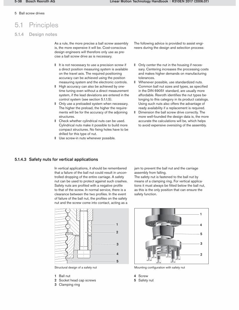
5-38 Bosch Rexroth AG
5
3
2
4
1
2
5
4
3
1
5 Ball screw drives
Linear Motion Technology Handbook R310EN 2017 (2006.07)
5.1.4 Design notes
5.1 Principles
It is not necessary to use a precision screw if a direct position measuring system is available on the travel axis. The required positioning accuracy can be achieved using the position measuring system and the electronic controls.High accuracy can also be achieved by one-time tuning even without a direct measurement system, if the lead deviations are entered in the control system (see section 5.1.1.5).Only use a preloaded system when necessary. The higher the preload, the higher the require-ments will be for the accuracy of the adjoining structures.Check whether cylindrical nuts can be used. Cylindrical nuts make it possible to build more compact structures. No fixing holes have to be drilled for this type of nut.Use screw-in nuts whenever possible.
Only center the nut in the housing if neces-sary. Centering increases the processing costs and makes higher demands on manufacturing tolerances.Whenever possible, use standardized nuts. Common ball nut sizes and types, as specified in the DIN 69051 standard, are usually more affordable. Rexroth identifies the nut types be-longing to this category in its product catalogs. Using such nuts also offers the advantage of ready availability if a replacement is required.Dimension the ball screw drive correctly. The more well-founded the design data is, the more accurate the calculations will be, which helps to avoid expensive oversizing of the assembly.
As a rule, the more precise a ball screw assembly is, the more expensive it will be. Cost-conscious design engineers will therefore only use as pre-cise a ball screw drive as is necessary.
The following advice is provided to assist engi-neers during the design and selection process:
5.1.4.3 Safety nuts for vertical applications
In vertical applications, it should be remembered that a failure of the ball nut could result in uncon-trolled dropping of the entire carriage. A safety nut can be used to protect against such crashes. Safety nuts are profiled with a negative profile to that of the screw. In normal service, there is a clearance between the two profiles. In the event of failure of the ball nut, the profiles on the safety nut and the screw come into contact, acting as a
jam to prevent the ball nut and the carriage assembly from falling.The safety nut is fastened to the ball nut by means of a clamping ring. For vertical applica-tions it must always be fitted below the ball nut, as this is the only position that can ensure the safety function.
Ball nutSocket head cap screwsClamping ring
1�2�3�
ScrewSafety nut
4�5�
Structural design of a safety nut Mounting configuration with safety nut

5-39Bosch Rexroth AG
5 Ball screw drives
Linear Motion Technology HandbookR310EN 2017 (2006.07)
5.1 Principles5.1.5 Mounting instructions
Ball screw drives are high-value machine parts that have a significant influence on the precision and service life of the entire machine. For this rea-son, the following ground rules must be followed during installation.
Appropriate lifting equipment must be used for long screws. The screw should be sup-ported at several points along its length to avoid excessive deflection (risk of permanent deformation).All mounting surfaces on the adjoining struc-ture must be clean and burr-free.For all screw connections, the permissible tightening torque must not be exceeded.The ball screw drive must be aligned parallel to the installed guide units.After installation, check whether the torque is constant over the entire stroke. If it is, the screw has been properly aligned. If the torque varies, the system can be optimized by re-aligning the end bearings.If it is necessary to remove the ball nut from the screw, a mounting arbor must be used to avoid losing balls. Disassembly should only be carried out by properly qualified and authorized personnel.Double nuts are systems that have been pre-cisely matched to the screw and should not be removed from it, as the set preload would then be lost.Ball nuts that have been installed without initial lubrication must be thoroughly lubricated be-fore the unit is started up for the first time.If any work such as drilling, welding or painting has to be performed near the ball screw drive after installation, the screw drive must be pro-tected with a cover before starting the work.The relevant mounting instructions contain additional important advice and recommen- dations.
Mounting arbor
When lifting, support the assembly at a sufficient number of points.

5-40 Bosch Rexroth AG
5 Ball screw drives
Linear Motion Technology Handbook R310EN 2017 (2006.07)
5.2 Ball nuts5.2.1 Single nuts
Single nuts are the most commonly used ball nuts. They are available in all the usual sizes, preloads and degrees of accuracy. They provide high performance in a compact unit. The systems with two (and sometimes even four) ball tracks achieve very high load ratings, thus offering long service life for customer applications.
The different series of single nuts cover a wide variety of applications:
Standard seriesMiniature serieseLINE seriesECOplus series with recirculation capsSpeed series with recirculation capsMachine Tool series
The single nuts in the Standard series essentially have the structural design described in section 5.1.1.1.
Unlike the Standard nuts, ECOplus ball nuts have no recirculation pieces but instead full plastic recirculation caps. This configuration makes them very economical.
Single nuts in the Speed series are characterized by their high maximum permissible linear speeds. This is due to the fact that their leads are equal to or greater than the nominal diameter.
Single nuts in the Machine Tool series are pre-loaded. The preload is achieved by shifting.
Examples of single nuts from the Rexroth range are shown in the illustrations at right.
Most common ball nutsMost common ball nuts
High performanceCompact designHigh performanceCompact design
Ball nut seriesBall nut series
The range of applications for single nuts is as broadly diversified as the range of versions avail-able. Single nuts are used in practically every machinery construction sector.
5.2.1.1 System characteristics
5.2.1.2 Application areas
Cylindrical single nut from the Standard series
Single nut from the ECOplus series with plastic recirculation caps
Single nut from the Speed series with plastic recirculation caps
Single nut from the Machine Tool series

5-41Bosch Rexroth AG
5 Ball screw drives
Linear Motion Technology HandbookR310EN 2017 (2006.07)
Standard series flanged nut
5.2 Ball nuts
5.2.2.2 Application areas
5.2.2 Standard series single nuts
5.2.2.1 System characteristics
Standard single nuts are the most common series with the greatest variety of ball nut types. The Standard series comprises flanged nuts and cylindrical nuts. Two of the flanged nuts are also available in adjustable preload versions. Adjust-able preload nuts have a narrow, adjustable slot running the length of the nut body. This design allows both zero backlash and adjustment of the preload to user requirements.
Single nuts in the Standard series are available with mounting dimensions per DIN 69051 part 5 or with Rexroth mounting dimensions. Matching nut housings and end bearings are also available in several versions for all Standard single nuts.
Most common seriesMost common series
Standardized designStandardized design
Because of the wide variety of nut types, Stan-dard series single nuts have a very broad range of applications. They can be used in virtually every area of the machinery construction sector.
Standard series flanged nut with single flat
Standard series cylindrical nut
Standard series adjustable preload nut

5-42 Bosch Rexroth AG
5 Ball screw drives
Linear Motion Technology Handbook R310EN 2017 (2006.07)
5.2.3.1 System characteristics
Miniature ball screw assemblies are convention-ally understood to be systems with a nominal diameter of less than 12 mm. Miniaturized nut geometries are achieved through the use of opti-mized recirculation systems and very small balls. These ball screws are usually not preloaded or only very slightly preloaded to ensure the smooth-est possible travel.
The illustration at right shows a typical nut from the miniature series.
Nominal diameter less than 12 mmNominal diameter less than 12 mm
Low preloadLow preload
5.2.3 Miniature series single nuts
5.2.3.2 Application areas
Because of their very compact design, miniature ball screw drives are used in all kinds of technical applications where the available space is limited.
Typical application areas are:Semi-conductor production and processingMedical technology (diagnosis, dispensing and rehabilitation)Automation (jigs and fixtures, handling systems, grippers and robots)Electrical engineering (switches)Process technology (valve and flap actuation)Manufacturing technology (small machines for miniature metal-cutting processes)
Miniature series flanged nut
5.2 Ball nuts

5-43Bosch Rexroth AG
5 Ball screw drives
Linear Motion Technology HandbookR310EN 2017 (2006.07)
5.2 Ball nuts
5.2.4.2 Application areas
5.2.4 eLINE series single nuts
5.2.4.1 System characteristics
eLINE ball screw drives are economical assem-blies for applications that do not make very high demands on accuracy, speed and rigidity. The use of alternative, rationalized manufacturing processes and a small range of standardized components makes it possible to produce very affordable drive solutions. eLINE ball nuts are supplied without preload on rolled screws with a lower level of accuracy.
The illustrations at right show two typical nuts from the eLINE series.
EconomicalEconomical
Without preloadWithout preload
These low-cost ball screw drives can be utilized in every technical field of application. Despite certain limitations in terms of performance (e.g. no preloading possible), they are vastly superior to acme screws.
Typical application areas are:Factory automation (workpiece transport and jigs and fixtures)Adjustable axes (woodworking and bending presses)Linear actuatorsErgonomics (table height adjustment)Transportation technology (door operation and lifting equipment)
eLINE series flanged nut with recirculation caps
eLINE series screw-in nut

5-44 Bosch Rexroth AG
5 Ball screw drives
Linear Motion Technology Handbook R310EN 2017 (2006.07)
5.2 Ball nuts
5.2.5.2 Application areas
5.2.5.1 System characteristics
Double nuts are classic examples of preloaded ball nuts with two-point contact. The preload is generated by tensioning the two halves of the double nut against each other on the screw (see section 5.1.1.3). Two-point contact ensures very smooth operation even with very high preloads.
Double nuts are relatively expensive because of their two-piece design (two complete nuts). The modular construction also results in very long component lengths, which must be taken into account when designing the adjoining structure.
Rexroth offers double nuts in two series: Standard seriesMachine Tool series
The double nuts are preloaded and run on special screws. The Machine Tool series has specifically optimized load ratings and travel speeds.
The illustrations at right show two typical double nuts.
PreloadTwo-point contactPreloadTwo-point contact
Modular constructionModular construction
Double nut seriesDouble nut series
Double nuts are mainly used in machine tools. The nuts are generally installed in axes with high accuracy and rigidity requirements. These may be, for instance, the main axes in grinding ma-chines and machining centers.
5.2.5 Double nuts
Standard series double nut
Machine Tool series double nut

5-45Bosch Rexroth AG
3
4
21
5
6
57
5 Ball screw drives
Linear Motion Technology HandbookR310EN 2017 (2006.07)
5.3 Drive units5.3.1 Drive units with driven screw
These readily available drive units offer users the opportunity to rapidly integrate economical drive solutions with minimal design and manufacturing effort. They combine all the performance charac-teristics of a classic ball screw drive in one unit. When paired with Rexroth linear guides, they offer machine designers full design freedom for every application.
Rexroth offers drive units with driven screw in two forms:
Open drive unit AOKDrive unit AGK with enclosure and sealing strip
The AOK drive unit is the classic ball screw assembly with pillow blocks and pre-assembled ball nut enclosure. A motor and gear unit can be supplied along with the unit, if so requested by the customer.
The drive units comprise a precision screw and a cylindrical single nut (with zero backlash or preloaded). The aluminum ball nut enclosure is finished on all sides and has reference edges on both sides. The pillow block units are made of robust extruded aluminum profile with reference edges on both sides and mounting holes as well as a locating feature for motor mounting.
The illustrations at right show AOK drive units with various motor attachment options.
Open drive units (AOK)Open drive units (AOK)
AOK drive unit
AOK drive unit with motor mount, coupling and motor
AOK drive unit with side drive timing belt and motor
Screw journalPillow block unitNut enclosure with ball nutScrewMotorMotor mount, couplingSide drive timing belt
1�2�3�4�5�6�7�
5.3.1.1 System characteristics
Operating principle of the driven screw

5-46 Bosch Rexroth AG
6
1
8
5
4
2
4
6
7
9
9
3
5 Ball screw drives
Linear Motion Technology Handbook R310EN 2017 (2006.07)
5.3 Drive units5.3.1 Drive units with driven screw
The AGK drive unit is available with optional screw supports (SS). These traveling screw supports are located on either side of the ball nut and support the screw radially against the enclosure. This allows the screw to rotate at high speed even in applications with long strokes. The number of screw supports is freely select-able and depends on the maximum permissible linear speed and the critical screw speed for the specific application.
Screw support (SS)Screw support (SS)
AGK drive unit
AGK drive unit with motor mount, coupling and motor
AGK drive unit with side drive timing belt and motor
AGK drive unit with screw supports
Screw journalDrive side pillow blockSealing stripCarriage with ball nutEnclosureMotorMotor mount and couplingSide drive timing beltScrew support
1�2�3�4�5�6�7�8�9�
The closed drive unit with ball screw assembly has the same basic structure as the AOK drive unit, but is additionally provided with an enclosure and sealing strip. This eliminates the need to design and install protective structures. The unit comes complete with aluminum extrusion profile encapsulation and a steel or polyurethane sealing strip.
The illustrations at right show AGK drive units with various motor attachment options.
Closed drive unit (AGK)Closed drive unit (AGK)

5-47Bosch Rexroth AG
1
2
5 Ball screw drives
Linear Motion Technology HandbookR310EN 2017 (2006.07)
5.3 Drive units5.3.1 Drive units with driven screw
The effect of the screw supports on the maxi-mum permissible linear speed is clear from the following example (see chart at right):A drive unit with a size 32 ball screw assem-bly with a lead of 32 mm and a screw length of 3500 mm can operate at a maximum linear speed of 17 m/min without screw supports. With 2 screw supports on each side of the ball nut, a maximum linear speed of 57 m/min is possible without reaching the critical screw speed range.
Drive units with driven screws and screw sup-ports are suitable for applications with very long strokes. The encapsulated design makes this solution ideal for woodworking environments and for use in water jet cutting applications.
The traveling screw supports act as floating bear-ings and reduce the free screw length between the nut and the end bearings. This increases the critical screw speed while reducing both screw deflection and the resonant energy introduced into the system due to screw whip.
Operating principle of the screw supportOperating principle of the screw support
5.3.1.2 Application areas
Ball screw assembly without screw supportsBall screw assembly with one traveling screw support on each side of the nut
1�2�
Operating principle of the screw support
Comparison of the maximum permissible linear speeds as a function of the number of screw supports, taking an AGK 32 drive unit with a 32x32 ball screw as an example
– Without screw support– With 1 screw support (on each side)– With 2 screw supports (on each side)– With 3 screw supports (on each side)
vperm = maximum permissible linear speed (m/min)Lmtg = mounting length (screw length) (mm)
v per
m (m
/min
)
Lmtg (mm)
0
20
40
60
80
100
50004000300020001000
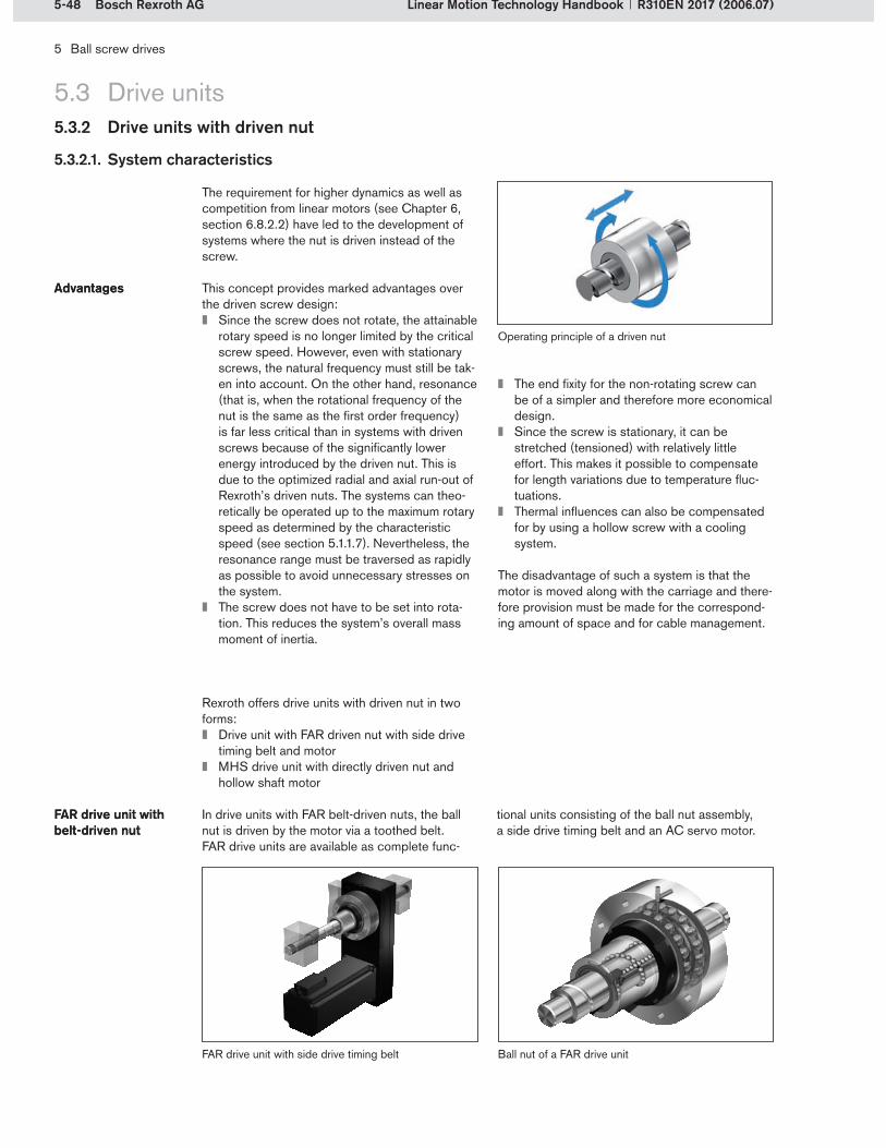
5-48 Bosch Rexroth AG
5 Ball screw drives
Linear Motion Technology Handbook R310EN 2017 (2006.07)
The requirement for higher dynamics as well as competition from linear motors (see Chapter 6, section 6.8.2.2) have led to the development of systems where the nut is driven instead of the screw.
This concept provides marked advantages over the driven screw design:
Since the screw does not rotate, the attainable rotary speed is no longer limited by the critical screw speed. However, even with stationary screws, the natural frequency must still be tak-en into account. On the other hand, resonance (that is, when the rotational frequency of the nut is the same as the first order frequency) is far less critical than in systems with driven screws because of the significantly lower energy introduced by the driven nut. This is due to the optimized radial and axial run-out of Rexroth’s driven nuts. The systems can theo-retically be operated up to the maximum rotary speed as determined by the characteristic speed (see section 5.1.1.7). Nevertheless, the resonance range must be traversed as rapidly as possible to avoid unnecessary stresses on the system.The screw does not have to be set into rota-tion. This reduces the system’s overall mass moment of inertia.
AdvantagesAdvantages
5.3.2.1. System characteristics
5.3 Drive units5.3.2 Drive units with driven nut
The end fixity for the non-rotating screw can be of a simpler and therefore more economical design.Since the screw is stationary, it can be stretched (tensioned) with relatively little effort. This makes it possible to compensate for length variations due to temperature fluc-tuations.Thermal influences can also be compensated for by using a hollow screw with a cooling system.
The disadvantage of such a system is that the motor is moved along with the carriage and there-fore provision must be made for the correspond-ing amount of space and for cable management.
Operating principle of a driven nut
FAR drive unit with side drive timing belt Ball nut of a FAR drive unit
Rexroth offers drive units with driven nut in two forms:
Drive unit with FAR driven nut with side drive timing belt and motorMHS drive unit with directly driven nut and hollow shaft motor
In drive units with FAR belt-driven nuts, the ball nut is driven by the motor via a toothed belt. FAR drive units are available as complete func-
tional units consisting of the ball nut assembly, a side drive timing belt and an AC servo motor.
FAR drive unit with belt-driven nutFAR drive unit with belt-driven nut

5-49Bosch Rexroth AG
5 Ball screw drives
Linear Motion Technology HandbookR310EN 2017 (2006.07)
5.3.2.2 Application areas
The advantages of driven nuts can be seen most clearly in applications with long strokes, e.g. grinding machine tables.
Drive units with directly driven nut and MHS hol-low shaft motor are the ideal solution for highly dynamic applications. The dynamic potential of the ball screw drive can be utilized to the fullest extent. Systems with driven nuts have been suc-cessfully incorporated in hexapods, for example. In these systems, the directly driven nuts are axially fixed and the screws perform the linear movements.
In MHS drive units, the nut is driven directly by a hollow shaft motor. The screw of the ball screw assembly is passed through the hollow rotor shaft of the servo motor.
Arranging the servo motor and the ball screw on one axis helps to save space. The nut is con-nected to the hollow shaft motor without any additional transmission elements. Transmission elements such as drive belts or couplings are eliminated together with their normally negative effects on precision.
MHS drive unit with hollow shaft motorMHS drive unit with hollow shaft motor
Structural design of the MHS drive unit
Functional unit consisting of a ball nut and hollow shaft motor mounted on the screw
Model of a hexapod with six MHS drive units
5.3 Drive units5.3.2 Drive units with driven nut

5-50 Bosch Rexroth AG
5 Ball screw drives
Linear Motion Technology Handbook R310EN 2017 (2006.07)
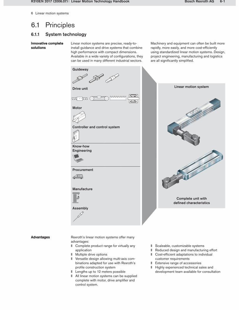
6-1Bosch Rexroth AG
6 Linear motion systems
Linear Motion Technology HandbookR310EN 2017 (2006.07)
6.1 Principles
Linear motion systems are precise, ready-to- install guidance and drive systems that combine high performance with compact dimensions. Available in a wide variety of configurations, they can be used in many different industrial sectors.
Innovative complete solutionsInnovative complete solutions
Machinery and equipment can often be built more rapidly, more easily, and more cost-efficiently using standardized linear motion systems. Design, project engineering, manufacturing and logistics are all significantly simplified.
Linear motion system
Guideway
Drive unit
Motor
Controller and control system
Know-howEngineering
Procurement
Manufacture
Assembly
Complete unit with defined characteristics
6.1.1 System technology
Rexroth’s linear motion systems offer many advantages:
Complete product range for virtually any applicationMultiple drive optionsVersatile design allowing multi-axis com- binations adapted for use with Rexroth’s profile construction systemLengths up to 12 meters possibleAll linear motion systems can be supplied complete with motor, drive amplifier and control system.
AdvantagesAdvantages
Scaleable, customizable systemsReduced design and manufacturing effortCost-efficient adaptations to individual customer requirementsExtensive range of accessoriesHighly experienced technical sales and development team available for consultation

6-2 Bosch Rexroth AG
6 Linear motion systems
Linear Motion Technology Handbook R310EN 2017 (2006.07)
6.1 Principles
A typical customer application for linear motion systems is illustrated below. A mass is to be moved over a certain distance within a defined time.
Customer applica-tions for linear motion systems
Customer applica-tions for linear motion systems
Important parameters for this are the installation space available, the prevailing environmental con-ditions and the accuracy and rigidity required.
Cycle time
Travel
Travel accuracy
Positioning accuracy
Deflection
Installation space
Environmental conditions
6.1.1 System technology
Essentially, a linear motion system can always be used whenever a linear movement is to be auto-mated. However, not all linear motion systems are suitable for all areas of application.
The application areas can be defined according to the tasks to be performed or by industrial sec-tors. Typical tasks for linear motion systems are:
Handling (pick and place)AssemblyMeasurement tasksProcessing/machining
Application areasApplication areas Linear motion systems can be used in every sector. They are particularly widespread in the following areas:
Electronics and semi-conductor manufacturingMedical technology and pharmaceuticals industry General factory automationWoodworkingFood and packaging industries
Linear speed
Rigidity
Mass
Parameters for using a linear motion system

6-3Bosch Rexroth AG
37
6
54
32
1
5
78
6
9
11
1
10
6 Linear motion systems
Linear Motion Technology HandbookR310EN 2017 (2006.07)
6.1 Principles6.1.1 System technology
6.1.1.1 Basic structural design of linear motion systems
Linear motion systems always have the same basic structure. They consist of the following components:
Load-bearing profile (frame) with guideway (6)Carriage with runner blocks (5)End blocks with bearings (3) or drive end enclosure (11) and tension end enclosure (9)Drive unit, i.e. ball screw drive (4), toothed belt drive (8), linear motor, etc.Cover (7), e.g. cover plate, sealing strip
AC servo motor, three-phase motor or step-ping motor (1) attached either directly via a motor mount with coupling (2) or via a gear unit (10), with a controller and control unitSwitches, socket and plug, cable ductOptional components such as screw supports, connection plates, clamping fixtures, position measuring systems, etc.
Compact module with ball screw drive
Linear module with toothed belt drive
Structural design of linear motion systems

6-4 Bosch Rexroth AG
3
4
1
5
2
4
21
6 Linear motion systems
Linear Motion Technology Handbook R310EN 2017 (2006.07)
The guideway assembly consists of a load- bearing profile as the frame (1) and the linear guides (2).
In most cases, the frame is fastened to the cus-tomer’s mounting base via clamping fixtures. It usually consists of an anodized aluminum ex-trusion profile, making the linear motion system highly rigid. The anodized coating enhances the frame’s visual appearance and protects the profile from scratches and corrosion. The TKK ball rail tables are also available with steel base plates, which offer even better rigidity and accuracy than the aluminum base plates. In PSK precision modules, the frame simultaneously serves as a U-shaped guide rail and is therefore always made from steel.
The actual guidance element in the linear motion system is the guide rail. This is fixed to the frame. The guide rail is either bolted down on the frame, staked into it as a dovetail profile, or integrated into the frame. In the case of cam roller guides, the guide shaft is pressed into the frame.The various guideway types are described in more detail in section 6.1.1.3.
Frame with linear guidewayFrame with linear guideway
6.1 Principles6.1.1 System technology
FrameGuide railCarriageToothed beltRunner block
1�2�3�4�5�
Carriage assembly
The carriage assembly generally consists of a compact aluminum profile with integrated or screw-fastened runner blocks. Customer-built attachments are usually mounted on the carriage.The carriage is fastened to the drive unit of the linear motion system. When the motor applies a drive torque, the drive unit sets the carriage in motion. Typical drive units are ball screw drives or toothed belt drives.
All linear motion systems are designed for one-point lubrication with grease. (Cam roller guides are lubricated with oil.) The guideways are lubri-cated via the carriage, either from the side (e.g., by hand) or from above via a customer-built lube system.
Carriage assemblyCarriage assembly
Lubrication via the carriage Lubrication via the carriage
Cross-section of a linear module with toothed belt drive
Frame with guide rails
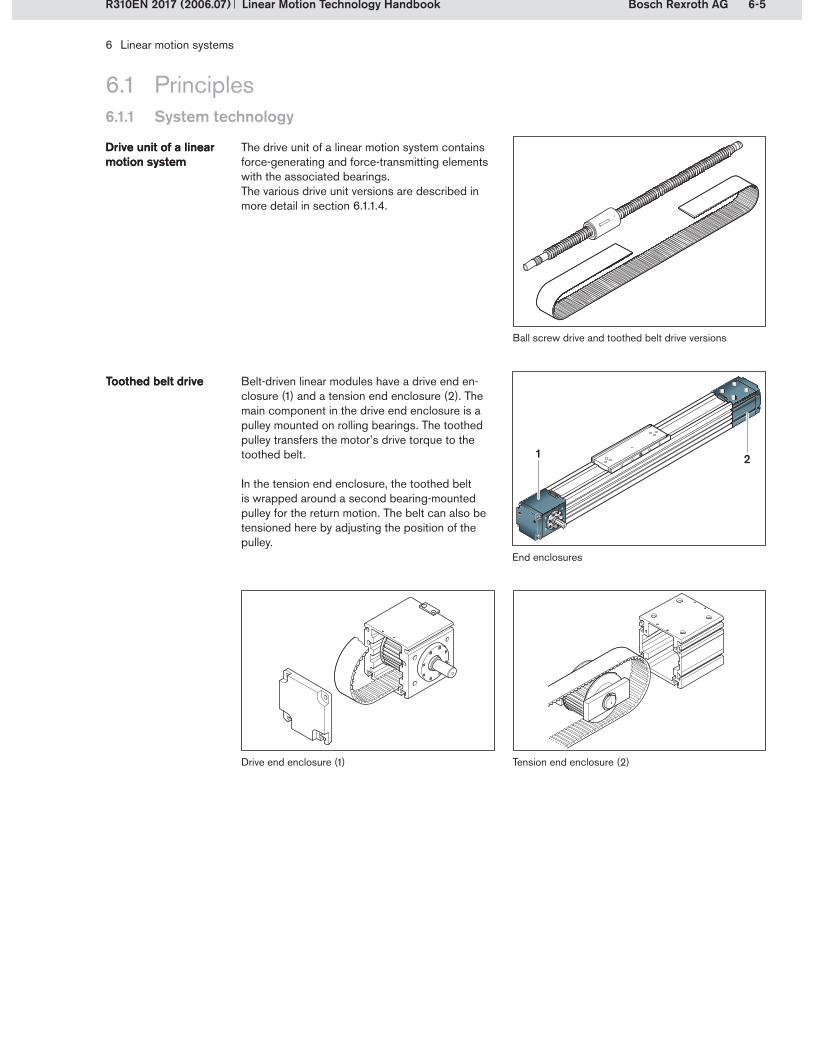
6-5Bosch Rexroth AG
1 2
6 Linear motion systems
Linear Motion Technology HandbookR310EN 2017 (2006.07)
6.1 Principles6.1.1 System technology
Drive end enclosure (1) Tension end enclosure (2)
Belt-driven linear modules have a drive end en-closure (1) and a tension end enclosure (2). The main component in the drive end enclosure is a pulley mounted on rolling bearings. The toothed pulley transfers the motor’s drive torque to the toothed belt.
In the tension end enclosure, the toothed belt is wrapped around a second bearing-mounted pulley for the return motion. The belt can also be tensioned here by adjusting the position of the pulley.
Toothed belt driveToothed belt drive
The drive unit of a linear motion system contains force-generating and force-transmitting elements with the associated bearings.The various drive unit versions are described in more detail in section 6.1.1.4.
Drive unit of a linear motion systemDrive unit of a linear motion system
End enclosures
Ball screw drive and toothed belt drive versions

6-6 Bosch Rexroth AG
1
2
6 Linear motion systems
Linear Motion Technology Handbook R310EN 2017 (2006.07)
6.1 Principles6.1.1 System technology
In linear motion systems with ball screw drive, the end enclosures are called end blocks. They accommodate the ball screw drive’s end bear-ings. The screw shaft journal protrudes from one of the two end blocks to allow connection of the screw to the motor.
Ball screw driveBall screw drive
End blocks
End block assembly with floating bearing (2)End block assembly with fixed bearing (1)
End blocks with buffers on a linear module with rack and pinion drive
In linear motion systems with a linear motor or rack and pinion drive, the end blocks serve both as end covers for the frame and as stops to pre-vent the carriage from overshooting the end of the frame.
Linear motorRack and pinion drive Linear motorRack and pinion drive
Drive end blockIdler end block
1�2�
End blocks with buffers on a linear module with linear motor

6-7Bosch Rexroth AG
6 Linear motion systems
Linear Motion Technology HandbookR310EN 2017 (2006.07)
Motor mount with coupling and stepping motor
Linear motion systems with ball screw drive, toothed belt drive or rack and pinion drive are driven by motors. Rexroth offers a broad range of AC servo motors, three-phase motors and step-ping motors. Depending on the application and the chosen combination of linear motion system and motor, the systems are driven either directly via a motor mount and coupling or indirectly via a gear unit. Timing belt side drives or planetary gears are used as gear units. A special form is a planetary gear unit that is integrated into the pul-ley in the drive end enclosure.
A locating feature and fastening thread are pro-vided to facilitate the attachment of the motor or gear unit. A coupling transfers the drive torque stress-free to the linear motion system’s drive shaft. Linear modules with rack and pinion drive are connected to the motor via a worm gear.
By using selectable gear ratios, the customer can adjust the drive torque to the specific application requirements and achieve the best match be-tween the external load and the motor’s moment of inertia. This is particularly important for optimiz-ing the drive control loop and for obtaining highly dynamic drives.
If a timing belt side drive is used, the overall length of the linear motion system can also be reduced compared to a configuration with direct motor attachment.
MotorsMotors
Gear unitsGear units
Gear unit as a timing belt side drive with servo motor
6.1 Principles6.1.1 System technology
Gear unit as a planetary gear with servo motor
Integrated planetary gear and servo motor

6-8 Bosch Rexroth AG
3
1 2
6 Linear motion systems
Linear Motion Technology Handbook R310EN 2017 (2006.07)
6.1 Principles6.1.1 System technology
Some linear motion systems come standard with a cover to protect them from contamination. A cover can also be installed as an option in other linear motion systems. The cover may be design-ed as a sealing strip, cover plate or bellows, as appropriate for the type of system.
CoverCover
Sealing strip
Integrated inductive measuring system on the ball rail system
Linear motion systems can be fitted with position measuring systems. The choice of measurement principle will depend on the type of linear motion system used. Available options are:
Optical systemsMagnetic systemsInductive systems
Measuring systems can also be supplied as:Rotary systems (rotary encoders)Linear systems (e.g. integrated measuring system from Rexroth, glass scale)
All measuring systems can either be integrated or mounted externally, depending on the system design.
Measuring systemsMeasuring systems
Sheet metal cover plate Bellows
Controllers and control units are available for all motor options. The complete unit, i.e. the linear motion system, motor, controller and control unit, can therefore be sourced directly from Rexroth.
Controllers and control unitsControllers and control units
Linear motion system complete with control unit, controller and motor
MotorController and control unitLinear motion system
1�2�3�

6-9Bosch Rexroth AG
43
21
5
6
7
6 Linear motion systems
Linear Motion Technology HandbookR310EN 2017 (2006.07)
6.1 Principles
Linear motion systems with ball screw drive can be equipped with screw supports as an option. Screw supports make it possible to increase the stroke length or to achieve a significant increase in the maximum permissible speed while maintain-ing the same stroke length. The maximum permis-sible rotary speed is determined by the screw’s critical speed.
Screw supportScrew support
Compact module with screw supports
For compact modules, connection plates (7) with the same T-slot design as the Rexroth con-struction profiles are available for connecting additional modules or for mounting of customer-built attachments. This enables the attachment of components to be standardized. For linear and compact modules, there are also connec-tion brackets (6) for building X-Y-Z combinations. Clamping fixtures (5) can be used to fasten the linear motion systems to the mounting base.
Connection elementsConnection elements
6.1.1 System technology
Switching system
There are various switching systems available for linear motion systems. These can be used as limit switches or reference switches. Normally, the switches used on linear modules are either me-chanical (2) or inductive (3). Compact modules are equipped with magnetic field sensors (Hall or Reed sensors).
The switch wiring can be grouped and routed through a socket and plug. As a result, only one cable is needed for connection to the controller.
A side-mounted cable duct (4) serves to protect the switch cables (see section 6.8.4).
Switching systemsSwitching systems
Socket and plugSocket and plug
Cable ductCable duct
PlugMechanical switchProximity switchCable duct
1�2�3�4�
Clamping fixtureConnection bracketConnection plate
5�6�7�
Connection elements

6-10 Bosch Rexroth AG
6 Linear motion systems
Linear Motion Technology Handbook R310EN 2017 (2006.07)
6.1 Principles
6.1.1.2 Type and size designations
For easy differentiation of the many versions of linear motion systems, Rexroth uses a simple identification system comprising a type and a size designation. The type designation consists of three letters, which define the type of system, guideway and drive unit used. This is followed by the size designation, which consists of the size of the linear guideway and the width of the frame.
The table below illustrates the coding system used for the type and size designations of Rexroth linear motion systems, using a compact module as an example. (The code letters are based on the German product names.)
Designation Type SizeExample: Compact Module C K K 20 - 145
SystemLinear Module, closed type (M) Linear Module, open type (L) Compact Module (C) Precision Module (P) Ball Rail Table (T) Linear Motion Slide (S)
C
GuidewayBall rail system (K) Integrated ball rail system (S) Cam roller guide (L) Linear bushing and shaft, closed type (G) Linear bushing and shaft, open type (O)
K
Drive unitBall screw drive (K) Toothed belt drive (R) Linear motor (L) Pneumatic drive (P) Rack and pinion drive (Z) Without drive (O)
K
Guideway dimension Rail width for ball rail systems
(Example: A = 20 mm)
20 -
Shaft diameter for cam roller guides Shaft diameter for linear bushings and shafts
Frame dimensionWidth of the frame or the base plate(Example: B = 145 mm)
145
6.1.1 System technology
Identification system for Rexroth linear motion systems
Example: Compact module CKK 20-145

6-11Bosch Rexroth AG
6 Linear motion systems
Linear Motion Technology HandbookR310EN 2017 (2006.07)
6.1 Principles
6.1.1.3 Guideway types
Rexroth uses three different kinds of guideways in its linear motion systems. Each of these offers different advantages, allowing the most appro-priate guideway to be selected for the specific application.
Detailed descriptions of the individual guideway types can be found in the related sections of the handbook (Chapter 3, section 3.2: Ball Rail Sys-tems; Chapter 3, section 3.6: Cam Roller Guides; Chapter 4: Linear Bushings and Shafts).
The guideways are always mounted to the frame. They are connected by screw fasteners and/or staking of the rail or shaft into the frame (ball rail system or cam roller guide). In the case of linear bushings and shafts, the shafts are fastened to shaft support rails or to shaft support blocks at the shaft ends (see Chapter 4).
The application requirements for rigidity and precision are important criteria for selecting the correct linear guideway. The rigidity of the over-all system depends on the type and number of guideways installed.
Guideway Example Characteristics
Ball rail system Compact module CKK
High rigidityHigh precisionComes standard with 2% C preloadTravel speeds up to 5 m/s possible
Cam roller guide Linear module MLR
Low noise levelHigh travel speeds up to 10 m/s possible
Linear bushing and shaft Linear motion slide SOK
Smooth runningInsensitive to dirtRobust (particularly the closed type)
Linear guideway typesLinear guideway types

6-12 Bosch Rexroth AG
1
23
4
5
1 2 4 5 3
6
1
63
1
1
3
6 Linear motion systems
Linear Motion Technology Handbook R310EN 2017 (2006.07)
6.1 Principles6.1.1 System technology
In addition to the choice of guideway type, the number of guideways installed is also an impor-tant factor determining the linear motion system’s
overall rigidity. The number of guide rails or shafts as well as the number of carriages may vary.
Number of guidewaysNumber of guideways
Linear module MKK with one rail guide (left) and compact module CKK with two rail guides
In linear modules and compact modules with the same rail size the load capacities and moments will differ according to:
Configuration with one or two rails One or more carriages
Load capacities and momentsLoad capacities and moments
Module Number of guide rails
Number of runner blocks
per rail
Dynamic load capacity C
of the guideway
Dynamic moments
Torsional moment Mt
Longitudinal moment ML
MKK 15-65 1 2 12 670 N 120 Nm 449 Nm
CKK 15-110 2 2 25 340 N 835 Nm 1 075 Nm
CarriageBall screw driveFrame
1�2�3�
Runner blockGuide railScrew journal for ball screw drive
4�5�6�
Compact module CKK with one carriage per rail (left) and with two carriages per rail
The table below gives a comparison of the load capacities and moments for two different linear motion systems:
Linear module MKK with one carriage running on a guide rail with two runner blocksCompact module CKK with two carriages run-ning on two guide rails with four runner blocks
The rail width is the same in both cases.

6-13Bosch Rexroth AG
2
1 1
6 Linear motion systems
Linear Motion Technology HandbookR310EN 2017 (2006.07)
6.1 Principles6.1.1 System technology
The system accuracy of two-rail systems is also higher than that of one-rail systems. The spacing between the supporting guide rails reduces geo-metric deviations due to yaw, pitch and roll.The precision module PSK is an exception here. Thanks to its U-shaped geometry with guide tracks (1) ground directly in the frame (2), this module can be used in applications requiring high precision and high rigidity.
System accuracySystem accuracy
Precision module PSK
The accuracy of the carriage with regard to yaw, pitch and roll is defined in the same way as for runner blocks (see Chapter 3, section 3.1.1).
Guideway Load capacity Preload possibilities
Rigidity Linear speed Travel accuracy
Noise char-acteristics
Ball rail system+++ +++ +++ ++ +++ ++
Cam roller guide+ ++ + +++ ++ +++
Linear bushing and shaft++ ++
++ 1)
+ 2) ++ ++ ++
The following table shows the characteristics of the different guideway types:
OverviewOverview
In linear motion systems the accuracy of the moved carriage is defined by:
the guideway accuracy P1, measured in the longitudinal direction along the carriage centerline, the parallelism P2 of the carriage surface to the base,the parallelism P3 of the carriage surface to the reference edge,the straightness P4 of the carriage in the longitudinal direction.
Accuracy criteria Accuracy criteria
Accuracy P1 Accuracy P2 Accuracy P3 Accuracy P4
longitud.
The nominal life of the guideway in the linear mo-tion system is calculated from the dynamic load capacity C of the guideway or of the complete carriage assembly.
Life expectancyLife expectancy Two-rail linear motion systems therefore have a longer life expectancy than linear motion systems with only one rail for the same guide rail size and external load.
Open typeClosed type
1)2)
+++ Very good ++ Good + Satisfactory

6-14 Bosch Rexroth AG
6 Linear motion systems
Linear Motion Technology Handbook R310EN 2017 (2006.07)
6.1 Principles6.1.1 System technology
6.1.1.4 Drive unit types
Drive unit Example Characteristics
Without drive Linear motion slide SGO
Manual movementRobust linear motion system
Ball screw Compact module CKK
High rigidity in the direction of travelHigh thrust forceRepeatability ± 0.005 mm (zero backlash)Travel speeds up to 1.6 m/s
Toothed belt Compact module CKR
High travel speeds up to 5 m/s (MLR module: up to 10 m/s)Low rigidity in the direction of travelRepeatability ± 0.1 mm
Rack and pinion Linear module MKZ
Allows long guideways lengthsTravel speeds up to 5 m/sAllows applications with multiple, independent carriagesLow noise
Linear motor Ball rail table TKL
High travel speeds up to 8 m/s and high acceleration ratesShort cycle timesHigh positioning accuracy and repeatabilityAllows applications with multiple, independent carriagesVirtually no down-time due to low number of wear partsMaintenance-free linear motorLow noise
Pneumatic Linear module MKP
No motor requiredTravel to fixed end positions (no intermediate positions)Travel speeds up to 2 m/s
The characteristics of linear motion systems are essentially determined by the type of drive unit used.
Rexroth offers a variety of drive unit options to cover many different applications.

6-15Bosch Rexroth AG
6 Linear motion systems
Linear Motion Technology HandbookR310EN 2017 (2006.07)
6.1 Principles6.1.1 System technology
The type of drive unit chosen determines the dy-namics (speed and acceleration) of the system and its positioning accuracy and repeatability. The duty cycle is influenced by the kinematic require-ments.
Due to their different designs, the drive units each have their own specific system characteristics. Linear motion systems therefore cover a broad range of customer applications. The structural design of the individual drive units is described in the following sections.
Drive unit types and system characteristics
Drive unit types and system characteristics
Screw and nut of a ball screw drive
In linear motion systems, ball screw drives are primarily used with zero-backlash cylindrical nuts. They are therefore particularly suitable for feed tasks requiring high precision.Ball screw drives are discussed in detail in Chapter 5.
Ball screwBall screw
Toothed belt drives are particularly suitable for highly dynamic applications. Toothed belts for lin-ear motion systems consist of abrasion-resistant polyurethane (PU) reinforced with high-strength steel cords.
The toothed belt is fastened to each end of the carriage by means of clamps. The drive end enclosure contains a pulley, through which the motor’s drive torque is applied and transferred to the belt. At the tension end, the toothed belt is wrapped around another pulley and tensioned to ensure smooth operation.
Toothed beltToothed belt
Toothed belt

6-16 Bosch Rexroth AG
6 Linear motion systems
Linear Motion Technology Handbook R310EN 2017 (2006.07)
6.1 Principles6.1.1 System technology
Because the thrust is generated directly, no addi-tional mechanical parts are required to convert ro-tary motion to linear motion. This means that there is no backlash and no mechanical compliance in the drive train, which results in unparalleled posi-tioning accuracy and repeatability throughout the life of the drive. Since linear motors have no internal moving parts such as those contained in rotary drive systems, they are not subject to wear and require no maintenance.
TKL ball rail table with linear motor
A linear motor is an electric motor that produces linear motion instead of rotary motion. The thrust force is generated directly at the moved part (car-riage). No additional drive element is required to transform and transmit the thrust. Linear motors are therefore also referred to as direct linear drives.
The key components of a linear motor are the carriage (primary element) and the secondary element with permanent magnets. Rexroth of- fers the secondary element in three versions: In linear modules LKL and MKL, a round thrust rod is connected to the frame via the end blocks. In the TKL ball rail table, the flat permanent mag-net and, in the case of the CKL compact module, the U-shaped permanent magnet is bolted direct-ly to the frame. The basic principle is the same for all versions and is described in section 6.8.2.2.
Linear motorLinear motor
In the case of rack and pinion drives, a helical-cut gear rack is mounted to the side of the frame. The pinion, worm gear and motor are mounted on the carriage. This makes it possible to move several carriages independently of each other and to build systems with long travel distances and high-speed motion. The low-backlash worm gear makes the rack and pinion drive highly rigid. The helical-cut teeth reduce the noise generated by the drive.
Rack and pinionRack and pinion
Rack and pinion drive

6-17Bosch Rexroth AG
6 Linear motion systems
Linear Motion Technology HandbookR310EN 2017 (2006.07)
6.1 Principles6.1.1 System technology
Pneumatic drives operate by means of a piston guided in a closed cylinder. Compressed air can be applied to one or both ends of the linear module and is supplied to the cylinder via internal air ducts. The compressed air moves the piston. A belt fastened to the piston and guided around pulleys in the end enclosures transmits the piston movement, i.e. the driving force, to the carriage. In pneumatic drives, the carriage can only travel full strokes, from end position to end position, or up to a shock absorber as a mechanical stop. Unlike all the other drive types, travel to intermediate positions is not possible.
The following table summarizes the characteris-tics of the various drives:
Pneumatic drivePneumatic drive
OverviewOverview
Linear module MKP
Drive unit Requirements
Thrust Rigidity Speed Precision 1) Noise char-acteristics
Ball screw +++ +++ + +++ ++
Toothed belt ++ + +++ + ++
Rack and pinion +++ +++ ++ ++ ++
Linear motor ++ +++ +++ +++ +++
Pneumatic + 0 + 0 ++
Depending on the measuring system used, its accuracy, and the control system
1) +++ Very good++ Good+ Satisfactory0 Adequate

6-18 Bosch Rexroth AG
6 Linear motion systems
Linear Motion Technology Handbook R310EN 2017 (2006.07)
6.1 Principles
6.1.2.1 Application parameters
Stroke lengthInstallation spaceLoadCycle times and linear speed
The size and type of the linear motion system is restricted by the load it will be required to carry. Two-rail compact modules have higher load capacities than one-rail linear modules with the same size of linear guide. This is also true for linear motion systems with several carriages.In general, loads of up to approximately 20% of the dynamic load and moment capacities (C, Mt, ML) have proven to be acceptable. The following limits should not be exceeded:
Permissible drive torqueMaximum permissible speedMaximum permissible forces and moments Maximum permissible deflection
The permissible drive torque, the maximum per-missible speed, and the permissible forces and moments are determined by the linear guides and drive units used. The product catalogs provide details of the dynamic characteristic values and the maximum permissible forces and moments.
LoadLoad
6.1.2 Product selection
The overall length of a linear motion system is calculated from the stroke length. The maximum achievable stroke length of a linear motion system will depend on the type of drive used. With ball screw drives, the problem of critical speed be-comes a factor beyond a certain length. For lon-ger lengths, toothed belt drives are more suitable.
Some linear motion systems with ball screw drives are available with screw supports. These shorten the free screw length and support the cover plate, which is also often present. This can significantly increase the permissible rotary speed and the stroke length.
Stroke lengthStroke length
Illustration of dynamic load and moment specifications
Repeatability and positioning accuracy Rigidity (including the mounting base)Environmental conditions
A suitable linear motion system can be pre-selected by analyzing and defining the following application parameters:
Often, several linear motion systems may be suitable for a particular application. In this case, or if special conditions make it difficult to deter-mine which linear motion system should be used,
customers can always call on Rexroth’s many years of experience. After pre-selecting the linear motion system, the next step is to perform the design calculations.
When selecting a linear motion system, care must be taken to ensure sufficient installation space (height, width and length). Depending on the con-figuration, the attachment of a motor can signifi-cantly increase the length or width of the linear motion system.
Installation spaceInstallation space

6-19Bosch Rexroth AG
6 Linear motion systems
Linear Motion Technology HandbookR310EN 2017 (2006.07)
6.1 Principles
Sample chart showing the deflection for a linear module MKK 20-80
L = module length (mm) = actual deflection (mm)max = maximum permissible deflection (mm)– Maximum permissible deflection depending
on the length of the linear motion system– Deflection under the given force
Linear motion systems are frequently not fully sup-ported but installed as unsupported structures, i.e. they are fastened to the adjoining customer-built structure at points close to the ends of the axes. In the unsupported configuration, deflection of the linear motion system must be taken into ac-count. If the maximum permissible deflection max is exceeded, additional support must be provided for the linear motion system. The maximum per-missible deflection max depends on the length of the linear axis and the load F. The corresponding charts in the product catalogs help in determining the maximum permissible deflection.
Regardless of the permissible deflection of the lin-ear motion system, the required system accuracy must also be taken into account. If necessary, the system must be supported at several points. The same applies when high demands are made on the system dynamics. Some versions, such as ball rail tables or precision modules, generally require to be mounted fully supported on a rigid customer-built structure to achieve the required precision.
DeflectionDeflection
6.1.2 Product selection
The required cycle times, and therefore the re-quired speeds, essentially determine the type of linear motion system to be used. Both the linear guide and the drive unit influence the maximum permissible speed.
Cycle times and speedsCycle times and speeds
Linear motion systems with cam roller guide and toothed belt drive or linear motor are particularly suitable for very high speeds.
Where good repeatability and positioning ac-curacy are required, ball rail tables or precision modules are an especially good choice. In this case, ball screws or linear motors are used as
Repeatability and positioning accuracyRepeatability and positioning accuracy
the drive. These provide clear advantages over toothed belt drives because of their high axial rigidity.
The rigidity perpendicular to the direction of travel is known as the radial rigidity. A linear motion system’s radial rigidity is essentially determined by the guide unit, the geometry of the frame and the mounting base. Ball rail systems are consider-ably more rigid than cam roller guides or linear bushing and shaft systems.
RigidityRigidity An appropriately designed mounting base can support the linear motion system in such a way that the application’s intrinsic rigidity will be sig-nificantly increased.
Some linear motion systems are more suitable than others for particular environmental condi-tions because of their design. In dirty or dusty environments, linear motion systems with cam roller guides or with additional covers are advan-tageous.
Environmental conditionsEnvironmental conditions
The following cover options are available:Without coverSteel sealing stripPolyurethane sealing strip BellowsGap-type sealing
1000 2000 3000 4000 5000 6000
1.5
2.5
3.5
0
4.5
1.00.5
2.0
3.0
4.0
0.0
F =
200
0 N
F =
250
0 N
F =
150
0 N
F =
100
0 N
F =
500
NF
= 2
50 N
F =
100
NF
= 0
N
L (mm)
(mm)
max

6-20 Bosch Rexroth AG
6 Linear motion systems
Linear Motion Technology Handbook R310EN 2017 (2006.07)
6.1 Principles6.1.2 Product selection
6.1.2.2 Product selection aids
Rexroth offers users a broad range of linear mo-tion systems in various designs and sizes. The selection criteria stated in section 6.1.2.1 enable
a suitable linear motion system to be found for almost any conceivable application.
Since all of the possible guides and drives can be combined, a linear motion system can be config-ured to match the specific requirements of any application. Sections 6.1.1.3 and 6.1.1.4 contain tables summarizing the characteristics of the dif-ferent guide and drive options.
Combinability of guides and drivesCombinability of guides and drives
However, because of the special demands on linear motion systems, not all combinations are sensible or cost-efficient. The following summary shows all the combinations offered by Rexroth:
System Guide unit Drive unit
Ball rail system
Cam roller guide
Linear bushing
and shaft
Without drive
Ball screw
Toothed belt
Rack and pinion
Pneu-matic
Linear motor
Linear module –
Compact module – – – –
Precision module – – – – – –
Ball rail table – – – – –
Linear motion slide – – – – – –
Linear motion system Load capacity Rigidity Precision Cover Maximum speed
Maximum length
Linear module MKK ++ ++ ++ +++ 1.6 m/s 6 000 mm
MKR ++ ++ + +++ 5.0 m/s 12 000 mm
MLR + + + +++ 10.0 m/s 10 000 mm
MKZ +++ +++ ++ + 2.2 m/s 6 000 mm
MKP + + 0 +++ 2.0 m/s 5 600 mm
MKL + ++ ++ +++ 5.0 m/s 2 000 mm
LKL + + ++ ++ 5.0 m/s 2 000 mm
Compact module CKK +++ +++ ++ ++ 1.6 m/s 5 500 mm
CKR +++ +++ + ++ 5.0 m/s 10 000 mm
CKL + + ++ + 5.0 m/s 2 800 mm
Precision module PSK ++ ++ +++ +++ 1.6 m/s 940 mm
Ball rail table TKK +++ ++ +++ ++ 1.6 m/s 2 860 mm
TKL +++ ++ +++ ++ 8.0 m/s 4 000 mm
Linear motion slide SGO ++ + 0 ++ Without drive 5 300 mm
SOO ++ ++ 0 ++ Without drive 5 300 mm
SGK ++ + + ++ 1.4 m/s 4 000 mm
SOK ++ ++ + ++ 1.4 m/s 4 000 mm
+++ Very good ++ Good + Satisfactory 0 Adequate
Generally, several different linear motion systems may represent a technically optimal solution for the linear motion requirements, so that economic and visual design aspects can also be consid-
ered. The following summary shows the various linear motion systems with the most important and logical selection criteria.

6-21Bosch Rexroth AG
6 Linear motion systems
Linear Motion Technology HandbookR310EN 2017 (2006.07)
6.1 Principles6.1.2 Product selection
6.1.2.4 Conditions of use
When selecting a linear motion system, the condi-tions of use for the customer’s application must also be taken into account. It is essential to check whether the linear motion system can be used in the given environment, whether there are any con-straints, or whether another linear motion system must be selected.
The following environmental factors in particular must be checked:
Dust, dirt, shavings, etc.TemperatureInstallation conditions and available space Shocks and vibrationsLubricationSpecial conditions of use
6.1.2.3 Motor, controller and control system
In addition to selecting the linear motion system itself, the necessary peripherals must also be considered. This involves specifying and calcu-lating the lubrication system, including in-service lubrication intervals, and, in particular, specifying the motor, controller and control system to be used. For all linear motion systems, Rexroth offers a large number of motors with controllers and control systems adapted to particular environ-ments and applications. For each type and each size of linear motion system, there is always a choice of several possible motors to cover dif-ferent speed and drive torque requirements.
Depending on the application, the most appropri-ate solution may be a servo motor, a three-phase motor or a stepping motor. Linear motors are a special case, as the motor is already integrated into the linear motion system.
The associated controllers and control systems enable the control loop to be optimally param-eterized to match the linear motion system to the specific customer application. More information on motor selection can be found in section 6.8 “Electrical components.”
Dust, dirt and shavings, etc. are crucial factors affecting the life expectancy of a linear motion system. Depending on the type and the quantity of foreign particles that a linear motion system will be exposed to, appropriate covers must be provided to ensure trouble-free operation and prolong the life of the guide and drive compo-nents.
Dust, dirt, shavings, etc.Dust, dirt, shavings, etc.
Essentially, it is possible to operate linear motion systems within a temperature range of 0°C to 40°C. The actual permissible operating tempera-ture can be limited by the guide system and the lubricant used.
TemperatureTemperature

6-22 Bosch Rexroth AG
6 Linear motion systems
Linear Motion Technology Handbook R310EN 2017 (2006.07)
6.1 Principles
The installation conditions (e.g. required operat-ing space, layout) often determine the type and size of linear motion system to be used. The spe-cific application determines whether a linear mo-tion system can be installed unsupported or must be supported. Some linear motion systems must be fully supported in order to ensure trouble-free operation and the required precision.
Installation conditions and available space
Installation conditions and available space
The space available can also affect the choice of linear motion system and motor attachment. The various drive configurations offered make it possible to adapt the systems flexibly to the given spatial conditions. Attaching the motor via a mo-tor mount and coupling (direct drive) extends the overall length of the linear motion system. Using a timing belt side drive enables the motor to be installed alongside, above or below the linear mo-tion system. The available installation space can be optimally exploited by selecting the appropri-ate motor attachment configuration.
Shocks and vibrations can have an adverse ef-fect on a linear motion system’s life expectancy. These effects can be minimized by selecting the appropriate linear motion system and sizing it accordingly.
The service life of a linear motion system also depends on adequate lubrication of the guideway and, where applicable, the ball screw assembly. The system can be lubricated manually via the lube nipples provided. Many linear motion sys-tems also offer the possibility of one-point lubrica-tion via the carriage. The advantage here is that a central lubrication system and lubricant dispenser
Shocks and vibrationsShocks and vibrations
LubricationLubrication can be used to ensure an adequate supply of lubricant to the system while it is in operation.
All of the rotary anti-friction bearings built into the linear motion systems (e.g. screw end bearings in the end enclosures) are lubricated for life and will not require in-service lubrication under normal conditions of use.
Special conditions of use for applications in clean rooms or under vacuum, for example, with corresponding application-specific parameters, are accounted for by specially designed linear motion systems. Chemical effects and aggressive media (metalworking fluids, solvents, vapor, etc.)
Special conditions of useSpecial conditions of use
also place particular demands on linear motion systems. The use of specially adapted lubricants and chemically resistant materials may be neces-sary here.
Normal conditions of use are considered to be:Use at room temperatureNo exceptionally high levels of contaminationNo exceptional shock and vibration loadsAdequate lubrication with an appropriate lubricant
Normal conditions of useNormal conditions of use
6.1.2 Product selection

6-23Bosch Rexroth AG
6 Linear motion systems
Linear Motion Technology HandbookR310EN 2017 (2006.07)
6.1 Principles6.1.3 Design notes
6.1.3.1 General design notes for linear motion systems
When designing machines, equipment and installations with linear motion systems, potential problems during later operation can be avoided by taking a number of basic precautions:
The maximum torque and speed of the motor must not exceed the limits for the linear motion system and the components used, such as the coupling.The attached motor may project into the work zone of neighboring systems. The linear motion system and its surroundings should therefore be checked for possible interfering edges.
Ensure compliance with the recommended lubrication intervals and the mounting, start-up and maintenance instructions.For short-stroke applications, make sure to schedule lubrication strokes. More information on short-stroke applications is provided in Chapter 2, section 2.4.2.2.
For vertically installed linear motion systems with a ball screw drive, the screw’s fixed bear-ing must be at the top to avoid the risk of the screw buckling.
Wherever possible, install the axis rotated through 180° (overhead mounting, carriage pointing downward). This will protect the linear motion system’s mechanical parts from dust.
Any special conditions of use and possible effects on materials should be discussed with Rexroth in advance (see section 6.1.2.4).
Linear motion systems with a linear motor (MKL, LKL, TKL, CKL) should preferably be installed horizontally.When installing linear motion systems in a vertical position, a braking device or coun-terweight must be provided to prevent the carriage from dropping if the motor has no brake (as is the case with a linear motor). The carriage must also be secured appropriately during transport.
Drive unitDrive unit
LubricationLubrication
Risk of bucklingRisk of buckling
Dust protectionDust protection
Special conditions of useSpecial conditions of use
Mounting orientationsMounting orientations

6-24 Bosch Rexroth AG
L
L7/3L7/2 L7/2
L
L9/3 L9/2L9/2L9/1 L9/1
6 Linear motion systems
Linear Motion Technology Handbook R310EN 2017 (2006.07)
6.1 Principles6.1.3 Design notes
Recommendations for lifting linear motion systems Strictly avoid any such lifting arrangements
Especially with long, and therefore heavy, linear motion systems there is a risk of signifi-cant deflection when lifting them, which could result in permanent deformation. Appropriate care must therefore be taken when handling the systems. Always use suitable lifting equip-ment. The lifting equipment must not damage the linear motion system and must minimize deflection.
TransportTransport

6-25Bosch Rexroth AG
6 Linear motion systems
Linear Motion Technology HandbookR310EN 2017 (2006.07)
6.1 Principles
When fastening linear motion systems to the mounting base, the following aspects must be taken into account because they have a signifi-cant effect on the system characteristics (e.g. service life, precision).
In the worst case, accuracy errors in the linear motion system and the mounting base may have a cumulative effect. If the foundation or the mounting base does not have the required accuracy, even very precise linear motion systems may not achieve the required overall system precision.
Linear motion systems may not be supported at the end enclosures or the end blocks. The frame is the main load-bearing structure.Standardized clamping fixtures, sliding blocks, threaded anchor strips, connection plates and brackets allow easy fastening of the linear motion systems to the mounting base or, in the case of multi-axis motion systems, easy connection of the individual linear components to one another. Rexroth offers these mounting accessories in versions suitably adapted for each linear motion system, thereby facilitating the design of these interfaces.The recommended number of clamping fix-tures per linear motion system should always be used.
In CKL compact modules, PSK precision mod-ules and TKK ball rail tables, a reference edge is provided on the side of the frame profile to facilitate alignment.
AccuracyAccuracy
Fastening optionsFastening options
Reference edgeReference edge
6.1.3.2 Fastening linear motion systems to the mounting base
Minimum clearances between the end enclosure and the mounting base
Fastening with clamping fixtures
Fastening with sliding blocks
6.1.3 Design notes
PSK precision module with reference edge
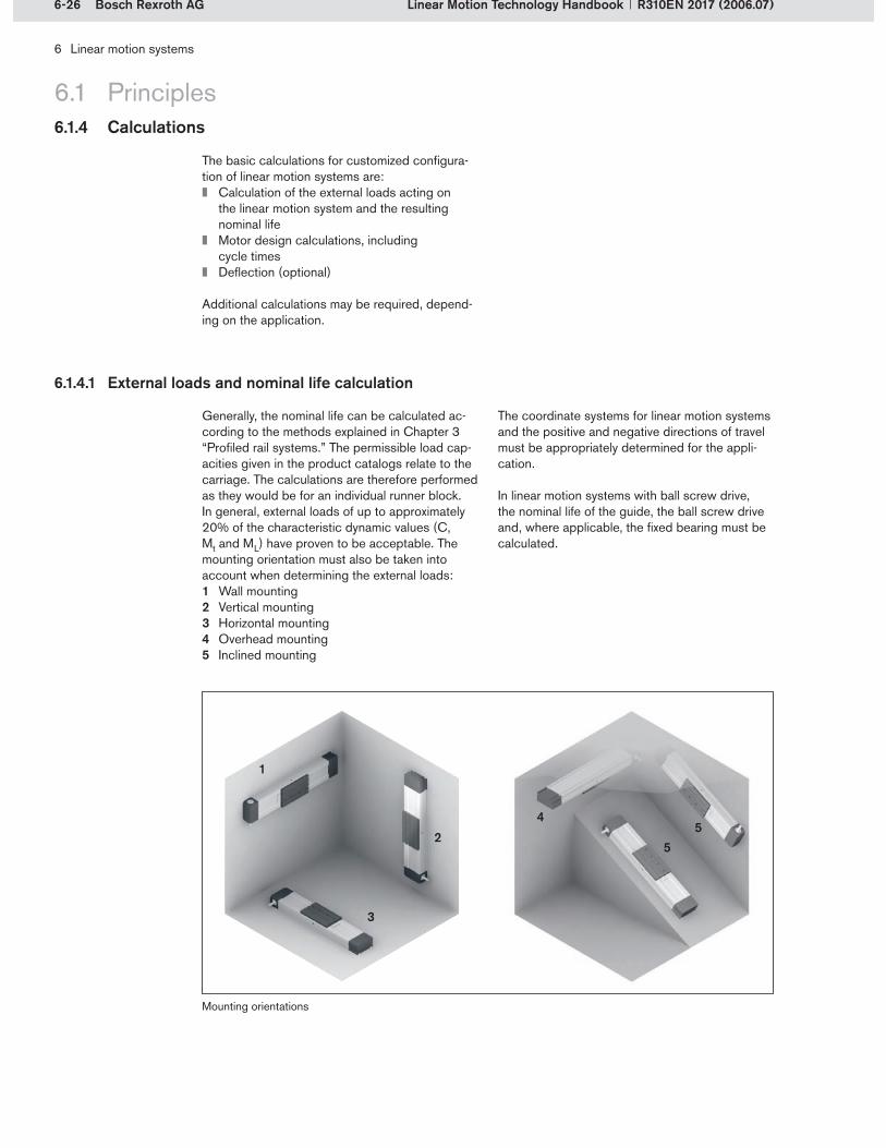
6-26 Bosch Rexroth AG
3
2
1
55
4
6 Linear motion systems
Linear Motion Technology Handbook R310EN 2017 (2006.07)
6.1 Principles
6.1.4.1 External loads and nominal life calculation
6.1.4 Calculations
The basic calculations for customized configura-tion of linear motion systems are:
Calculation of the external loads acting on the linear motion system and the resulting nominal life Motor design calculations, including cycle times Deflection (optional)
Additional calculations may be required, depend-ing on the application.
Generally, the nominal life can be calculated ac-cording to the methods explained in Chapter 3 “Profiled rail systems.” The permissible load cap-acities given in the product catalogs relate to the carriage. The calculations are therefore performed as they would be for an individual runner block. In general, external loads of up to approximately 20% of the characteristic dynamic values (C, Mt and ML) have proven to be acceptable. The mounting orientation must also be taken into account when determining the external loads:
Wall mountingVertical mountingHorizontal mountingOverhead mountingInclined mounting
1�2�3�4�5�
Mounting orientations
The coordinate systems for linear motion systems and the positive and negative directions of travel must be appropriately determined for the appli-cation.
In linear motion systems with ball screw drive, the nominal life of the guide, the ball screw drive and, where applicable, the fixed bearing must be calculated.
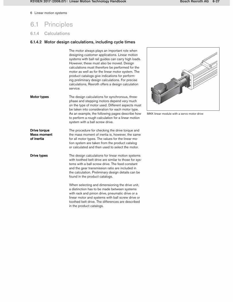
6-27Bosch Rexroth AG
6 Linear motion systems
Linear Motion Technology HandbookR310EN 2017 (2006.07)
6.1 Principles6.1.4 Calculations
6.1.4.2 Motor design calculations, including cycle times
The motor always plays an important role when designing customer applications. Linear motion systems with ball rail guides can carry high loads. However, these must also be moved. Design calculations must therefore be performed for the motor as well as for the linear motor system. The product catalogs give indications for perform-ing preliminary design calculations. For precise calculations, Rexroth offers a design calculation service.
The design calculations for synchronous, three-phase and stepping motors depend very much on the type of motor used. Different aspects must be taken into consideration for each motor type. As an example, the following pages describe how to perform a rough calculation for a linear motion system with a ball screw drive.
The procedure for checking the drive torque and the mass moment of inertia is, however, the same for all motor types. The values for the linear mo-tion system are taken from the product catalog or calculated and then used to select the motor.
Motor typesMotor types
Drive torque Mass moment of inertia
Drive torque Mass moment of inertia
The design calculations for linear motion systems with toothed belt drive are similar to those for sys-tems with a ball screw drive. The feed constant and the gear transmission ratio are included in the calculation. Preliminary design details can be found in the product catalogs.
When selecting and dimensioning the drive unit, a distinction has to be made between systems with rack and pinion drive, pneumatic drive or a linear motor and systems with ball screw drive or toothed belt drive. The differences are described in the product catalogs.
Drive typesDrive types
MKK linear module with a servo motor drive
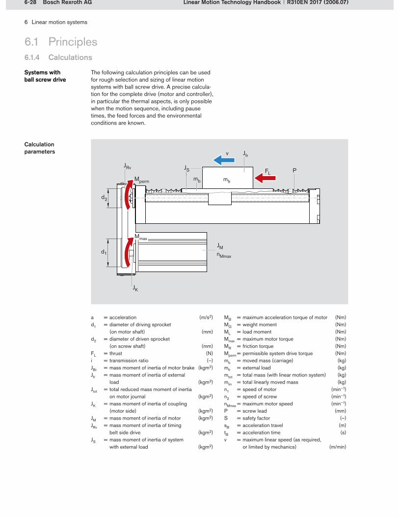
JBR ergänzen?
6-28 Bosch Rexroth AG
6 Linear motion systems
Linear Motion Technology Handbook R310EN 2017 (2006.07)
6.1.4 Calculations
6.1 Principles
a = acceleration (m/s2)d1 = diameter of driving sprocket
(on motor shaft) (mm)d2 = diameter of driven sprocket
(on screw shaft) (mm)FL = thrust (N)i = transmission ratio (–)JBr = mass moment of inertia of motor brake (kgm2)Jfr = mass moment of inertia of external
load (kgm2)Jtot = total reduced mass moment of inertia
on motor journal (kgm2)JK = mass moment of inertia of coupling
(motor side) (kgm2)JM = mass moment of inertia of motor (kgm2)JRv = mass moment of inertia of timing
belt side drive (kgm2)JS = mass moment of inertia of system
with external load (kgm2)
MB = maximum acceleration torque of motor (Nm)MG = weight moment (Nm)ML = load moment (Nm)Mmax = maximum motor torque (Nm)MR = friction torque (Nm)Mperm = permissible system drive torque (Nm)mb = moved mass (carriage) (kg)mfr = external load (kg)mtot = total mass (with linear motion system) (kg)mlin = total linearly moved mass (kg)n1 = speed of motor (min–1)n2 = speed of screw (min–1)nMmax = maximum motor speed (min–1)P = screw lead (mm)S = safety factor (–)sB = acceleration travel (m)tB = acceleration time (s)v = maximum linear speed (as required,
or limited by mechanics) (m/min)
Calculation parameters
The following calculation principles can be used for rough selection and sizing of linear motion systems with ball screw drive. A precise calcula-tion for the complete drive (motor and controller), in particular the thermal aspects, is only possible when the motion sequence, including pause times, the feed forces and the environmental conditions are known.
Systems with ball screw driveSystems with ball screw drive
JRv JS
d2
d1
JM
Mperm mfr
Mmax
nMmax
v Jfr
FLmb
P
JK

6-29Bosch Rexroth AG
(6-4)
(6-2)
(6-9)
(6-7)
(6-8)
(6-1)
mlin = mb + mfr(6-5)
(6-6)
(6-3)
6 Linear motion systems
Linear Motion Technology HandbookR310EN 2017 (2006.07)
6.1 Principles
Horizontal mounting orientation:Conditions:Mmax MpermML must be added if acting in the direction of move-ment, subtracted if acting counter to the direction of movement.
Conditions:S · MG MbrakeS 2 (recommended)
mtot according to the calculation in the respective linear motion system product catalog, plus weight of motor, coupling or timing belt side drive, trailing cables
Servo motor acceler-ation characteristics
Weight moment (vertical mounting orientation)
The calculations for stepping motors are per-formed in a similar manner, but with certain con-straints. Rexroth provides assistance on request.
Mass moment of inertia of system with external load
Mass moment of inertia on motor journal
6.1.4 Calculations
Vertical mounting orientation:
Conditions:for handling Jfr < 6 · JMfor processing Jfr < 1.5 · JM
JS from the respective linear motion system product catalog
JS from the respective linear motion system product catalog JM see motor data in the product catalog
Motor attachment via motor mount and coupling:
Motor attachment via timing belt side drive:
mlin = mtot – mb
MB = 0.8 · Mmax - MR - MG ± ML
MG = · mlin · P1.561 · 103
i
MB = 0.8 · Mmax - MR ± ML
ML = · FL · P1.592 · 104
i
Jtot = + JM + JK + JRv + JBrJS i2
Base plate fixed, carriage travels:
Carriage fixed, base plate travels:

6-30 Bosch Rexroth AG
(6-12)
(6-13)
(6-14)
LL/2
!
F
(6-10)
i = d2d1
= n1n2
(6-11)
6 Linear motion systems
Linear Motion Technology Handbook R310EN 2017 (2006.07)
Acceleration travel
Acceleration time
Acceleration
6.1.4 Calculations
6.1 Principles
6.1.4.3 Deflection
A particular feature of linear and compact mod-ules is that they can be installed without sup-ports. Deflection must, however, be taken into consideration, because it limits the possible load.
The maximum permissible deflection max depends on:
the external load F,the length L,the rigidity of the linear motion system,the rigidity of the mounting base and the bearings.
Unsupported installationUnsupported installation
The maximum permissible deflection max must not be exceeded. If the deflection is too great or if high system dynamics are required, supports must be provided every 300 to 600 mm (1).
The deflection can affect the life expectancy. Normally, this is not taken into account when calculating the nominal life.
Deflection in an unsupported installation
Conditions: n1 nMmax
v from the respective linear motion system product catalog
1
tB = Jtot ·n1 · 0.10472
MB
sB = 0.5 · a · tB2
Speed

6-31Bosch Rexroth AG
6 Linear motion systems
Linear Motion Technology HandbookR310EN 2017 (2006.07)
6.2 Linear modules
Available in many different versions, linear mod-ules can be used in a wide variety of applications. All of the drive types in the Rexroth range are used in linear modules. The guideways can be either ball rail systems or cam roller guides.
All drive typesAll drive types
Ball rail systemCam roller guideBall rail systemCam roller guide
Linear module MKR with toothed belt drive on a Rexroth construction profile
Drive unit Guideway
Ball rail system Cam roller guide
Ball screw MKK –
Toothed belt MKR MLR
Rack and pinion MKZ –
Pneumatic MKP –
Linear motor MKL/LKL –
All linear modules can be delivered in any desired length, i.e. each module can be cut to length with millimeter accuracy to suit the customer’s application.All linear module types are generally available in lengths up to 6 m, the actual length depend-ing on the size and the drive type. Modules with toothed belt drive (MKR) can even be manufactured in lengths of up to 12 m.The largest linear module sizes can move masses of up to 1000 kg.MLR modules with cam roller guide can travel at speeds of up to 10 m/s.
FeaturesFeatures
6.2.1 System characteristics
MKK linear modules with ball screw drive achieve a repeatability of up to 0.005 mm and a positioning accuracy of up to 0.01 mm.If required, the linear modules can be equip-ped with direct measuring systems. Direct travel measurement improves the positioning accuracy.Depending on the type and size, linear modules can be covered with a steel or poly- urethane sealing strip or with bellows to pro-tect the guideway and the drive unit from dirt.Carriages are available in different lengths and versions (with threaded holes or T-slots).
Linear modules are recognizable by their almost square cross-section. Most modules are equip-ped with one ball rail guideway. The MKZ and one MKR size have two ball rail systems, and the
MLR series has one cam roller guideway. The versions with two rails are particularly suitable for very high moment loads.
In MKK modules, the motor is attached via a motor mount and coupling, and in MKR modules via a gear reducer. Timing belt side drives can be
Motor attachmentMotor attachment fitted to all linear modules with ball screw drive. Toothed belt driven linear modules are also avail-able with a gear unit.

6-32 Bosch Rexroth AG
v (m
/min
)
L (mm)
1
23
4
1
5
6
2
6 Linear motion systems
Linear Motion Technology Handbook R310EN 2017 (2006.07)
6.2 Linear modules6.2.2 Linear modules MKK with ball rail system and ball screw drive
The ball screw drive in MKK linear modules enables a very high level of positioning accuracy with simultaneously high load capacities when adjusted to zero backlash. Through the special design of the ball screw end bearings, MKK linear modules can achieve higher travel speeds than normal for linear motion systems of this kind.
High precision and high load capacitiesHigh precision and high load capacities
Linear module MKK 25-110 with screw supports
Permissible speeds with and without screw supports for a linear module MKK 25-110
L = module length (mm)v = travel speed (m/min)– Permissible speed without SS– Permissible travel speed with 1 SS
(on either side of the carriage)– Permissible travel speed with 2 SS (on either side of the carriage)
The travel speed and the module length are restricted by the ball screw’s critical speed (see Chapter 5, section 5.1.3.3).
One size of the MKK linear module series can be fitted with screw supports. This significantly extends the permissible length and enables travel at high speed over the entire length.
The example below, based on the data for an MKK 25-110 linear module, clearly shows the effect of the screw supports (SS) on the length. Travel at maximum speed can be achieved over significantly longer strokes.
Screw supportsScrew supports
ExampleExample
Ball screwGuide railScrew support (only in one MKK size)CarriageFrameRunner block
1�2�3�4�5�6�
Structural design of a linear module MKK

6-33Bosch Rexroth AG
6
23
4
5
7
8
9
7
6
7
10
9
7
1
6 Linear motion systems
Linear Motion Technology HandbookR310EN 2017 (2006.07)
6.2 Linear modules6.2.3 Linear modules MKR/MLR with ball rail system/cam roller guide and toothed belt drive
MKR and MLR linear modules are particularly suitable for applications with high travel speeds because of the toothed belt drive. They can be supplied with a separate gear unit or with an in-tegrated gear reducer. In the case of integrated gear reducers, the planetary gears are located in the module’s belt pulley (3), ensuring very compact construction. Different gear transmis-sion ratios allow optimum matching of the external load and the motor’s inertia. This results in a high-ly dynamic drive.
The guideway is sealed off against dirt by gap-type sealing and by the fact that the toothed belt runs inside the frame. This sealing system is maintenance-free.
In very dirty environments, the MKR module can be fitted with a sealing strip to provide additional protection.
High speedsHigh speeds
Gear reducerGear reducer
Sealing systemSealing system
Sealing strip Sealing strip
Linear module MKR with sealing strip
Linear module MLR with cam roller guideLinear module MKR with ball rail system
Sealing stripDrive end blockBelt sprocket with integrated gear reducerMotor mountMotor
1�2�3�4�5�
CarriageToothed beltBall rail systemFrameCam roller guide
6�7�8�9�10�
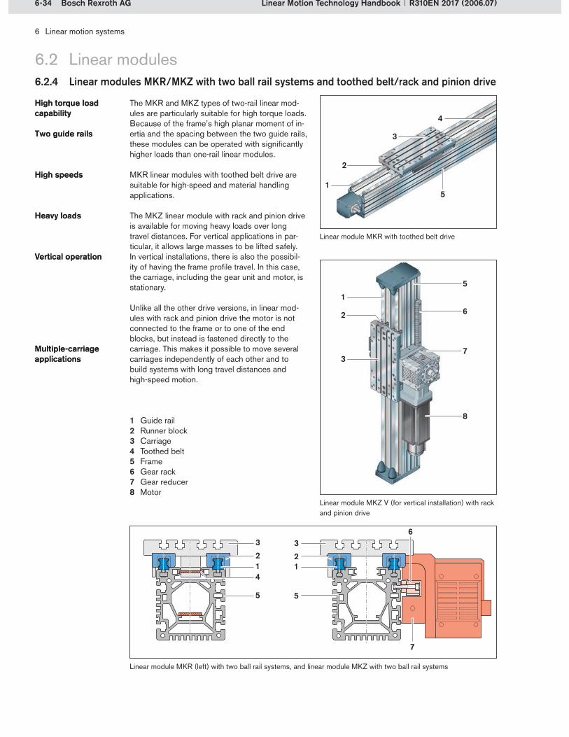
6-34 Bosch Rexroth AG
4
3
5
2
1
6
73
2
8
5
321
5
3
5
4
21
6
7
1
6 Linear motion systems
Linear Motion Technology Handbook R310EN 2017 (2006.07)
6.2 Linear modules6.2.4 Linear modules MKR/MKZ with two ball rail systems and toothed belt/rack and pinion drive
The MKR and MKZ types of two-rail linear mod-ules are particularly suitable for high torque loads. Because of the frame’s high planar moment of in-ertia and the spacing between the two guide rails, these modules can be operated with significantly higher loads than one-rail linear modules.
MKR linear modules with toothed belt drive are suitable for high-speed and material handling applications.
The MKZ linear module with rack and pinion drive is available for moving heavy loads over long travel distances. For vertical applications in par-ticular, it allows large masses to be lifted safely. In vertical installations, there is also the possibil-ity of having the frame profile travel. In this case, the carriage, including the gear unit and motor, is stationary.
High torque load capabilityHigh torque load capability
Two guide railsTwo guide rails
High speedsHigh speeds
Heavy loadsHeavy loads
Vertical operationVertical operation
Unlike all the other drive versions, in linear mod-ules with rack and pinion drive the motor is not connected to the frame or to one of the end blocks, but instead is fastened directly to the carriage. This makes it possible to move several carriages independently of each other and to build systems with long travel distances and high-speed motion.
Multiple-carriage applicationsMultiple-carriage applications
Linear module MKZ V (for vertical installation) with rack and pinion drive
Linear module MKR (left) with two ball rail systems, and linear module MKZ with two ball rail systems
Guide railRunner blockCarriageToothed beltFrame Gear rackGear reducerMotor
1�2�3�4�5�6�7�8�
Linear module MKR with toothed belt drive

6-35Bosch Rexroth AG
1
3
7
8
4
6
5
1
4
3
4
9
6
2
6 Linear motion systems
Linear Motion Technology HandbookR310EN 2017 (2006.07)
6.2.5 Linear modules MKP with ball rail system and pneumatic drive
6.2 Linear modules
In MKP linear modules, the carriages are driven purely by pneumatic power, i.e. with compressed air. An electric motor is not required.
In pneumatic drives, the carriage can only travel full strokes, from end position to end position, or up to a shock absorber as a mechanical stop. Un-like all the other drive types, travel to intermediate positions is not possible.
The shock absorbers and adjustable pneumatic end position cushioning allow impact-free braking even from high speeds.
Pneumatic drivePneumatic drive
Travel between end positionsTravel between end positions
Shock absorbersShock absorbers
Double-acting piston of the pneumatic driveBeltCarriageFrameCylinder integrated into the frameEnd block with pulleyRunner blockGuide railShock absorber
1�2�3�4�5�6�7�8�9�
Shock absorber for linear module MKP
The design calculations for MKP linear modules differ from those for the other modules. The spe-cial features of these calculations are explained in the product catalog.
Design calculationsDesign calculationsLinear module MKP with pneumatic drive
Structural design of linear module MKP
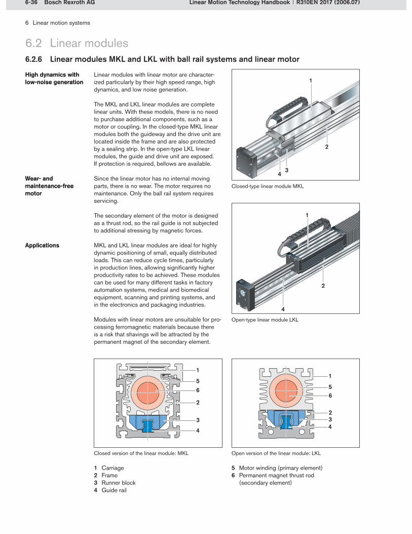
6-36 Bosch Rexroth AG
6
32
56
3
4
1
2
5
1
4
3
1
4
2
4
1
2
6 Linear motion systems
Linear Motion Technology Handbook R310EN 2017 (2006.07)
6.2.6 Linear modules MKL and LKL with ball rail systems and linear motor
6.2 Linear modules
Linear modules with linear motor are character-ized particularly by their high speed range, high dynamics, and low noise generation.
The MKL and LKL linear modules are complete linear units. With these models, there is no need to purchase additional components, such as a motor or coupling. In the closed-type MKL linear modules both the guideway and the drive unit are located inside the frame and are also protected by a sealing strip. In the open-type LKL linear modules, the guide and drive unit are exposed. If protection is required, bellows are available.
Since the linear motor has no internal moving parts, there is no wear. The motor requires no maintenance. Only the ball rail system requires servicing.
The secondary element of the motor is designed as a thrust rod, so the rail guide is not subjected to additional stressing by magnetic forces.
MKL and LKL linear modules are ideal for highly dynamic positioning of small, equally distributed loads. This can reduce cycle times, particularly in production lines, allowing significantly higher productivity rates to be achieved. These modules can be used for many different tasks in factory automation systems, medical and biomedical equipment, scanning and printing systems, and in the electronics and packaging industries.
Modules with linear motors are unsuitable for pro-cessing ferromagnetic materials because there is a risk that shavings will be attracted by the permanent magnet of the secondary element.
High dynamics with low-noise generationHigh dynamics with low-noise generation
Wear- and maintenance-free motor
Wear- and maintenance-free motor
ApplicationsApplications
Closed-type linear module MKL
Open-type linear module LKL
Closed version of the linear module: MKL Open version of the linear module: LKL
CarriageFrameRunner blockGuide rail
1�2�3�4�
Motor winding (primary element)Permanent magnet thrust rod (secondary element)
5�6�

6-37Bosch Rexroth AG
4
2
3
1
1
2
11
1
1
5
6
6 Linear motion systems
Linear Motion Technology HandbookR310EN 2017 (2006.07)
6.2.7 Connection elements for linear modules
6.2 Linear modules
The robotic erector system for Rexroth linear modules helps users to install and attach linear modules more easily and to connect linear mod-ules to one another.
Modules with ball screw drive and toothed belt drive can thus be combined. The basic elements (plates and brackets) have been designed to allow modules to be connected to other modules of the same size or one size larger or smaller. Connecting shafts allow two linear modules with toothed belt drive to operate in parallel.
The connecting elements also allow quick and easy adaptation to the profiles and frames in Rexroth’s basic mechanical elements (BME) range. Linear modules can also be connected to other linear motion systems such as compact modules or ball rail tables.
Since the connecting elements are standardized, mass-produced components, they help users to cut their own design and manufacturing costs and to respond flexibly to different linear motion requirements and applications.
Combination of MKK, MKR and MLRCombination of MKK, MKR and MLR
Connection plates, connection bracketsConnection plates, connection brackets
Connection shaftsConnection shafts
Basic mechanical elements rangeBasic mechanical elements range
FeaturesFeatures Linear moduleConnection bracketBME profileConnection plateClamping fixtureConnecting shaft
1�2�3�4�5�6�
Linear module fixed to BME profile via a connection bracket; stationary carriage, moving frame
Linear module connection and combination possibilities

6-38 Bosch Rexroth AG
6 Linear motion systems
Linear Motion Technology Handbook R310EN 2017 (2006.07)
6.3 Compact modules
Compact modules are characterized by their high power density. All compact module types are equipped with two ball rail systems and optionally with one or two carriages. Two carriages enable even higher loads to be carried.
Compact modules are recognizable by their rela-tively flat construction. The ratio of width to height is approximately 2:1 for all types and sizes. In comparison to linear modules with the same size of ball rails, the profile cross-section is smaller although higher loads are possible.
Rexroth offers the following versions in the Compact module range:
CKK compact module with ball screw driveCKR compact module with toothed belt driveCKL compact module with linear motor
The CKK and CKR versions are closed-type modules, while the CKL series is open.
In the CKK and CKR series, the motor is attach-ed via a motor mount and coupling. A timing belt side drive can also be attached to compact modules of the CKK type. Toothed belt-driven compact modules are available with a separate gear unit or an integrated gear reducer.
All compact modules can be delivered in any desired length to suit the customer’s wishes.CKR compact modules are available in lengths up to 10 m, depending on the size. CKK mod-ules have a maximum possible length of 5.5 m. CKL modules are available up to 2.8 m.Compact modules are particularly suitable for very high torsional and longitudinal moments. The versions with two carriages per guide rail can withstand particularly high longitudinal moment loads.The largest versions of compact modules can move masses up to 200 kg.CKK compact modules with ball screw drive achieve a repeatability of up to 0.005 mm and a positioning accuracy of up to 0.01 mm.For high positioning accuracy, compact mod-ules can be equipped with linear encoders.
High power density Compact designHigh power density Compact design
Low profileLow profile
Small profile cross-sectionSmall profile cross-section
Motor attachmentMotor attachment
FeaturesFeatures
Compact module CKK with ball screw drive
6.3.1 System characteristics
Torsional and longitudinal moments

6-39Bosch Rexroth AG
1 57 8433 2
1
5
6
3
2
3
2
1
54
6 Linear motion systems
Linear Motion Technology HandbookR310EN 2017 (2006.07)
6.3 Compact modules6.3.2 Compact modules CKK with ball rail systems and ball screw drive
Through the special design of the ball screw end bearings, CKK compact modules can achieve higher travel speeds than normal for linear motion systems of this kind. However, the speed and the module length will always be restricted by the ball screw drive’s critical speed.
Users can choose between modules with one or two carriages, as appropriate for the application and the load. Versions with two carriages are used for particularly high loads.
The drive unit and the guideways are protected by an aluminum cover and two gap-type seals made from polyurethane strip.
One size of the CKK compact module series can be fitted with screw supports. This enables high travel speeds to be achieved over the entire length.
Higher speedsHigher speeds
Two carriagesTwo carriages
Sealing systemSealing system
Screw supportsScrew supports
Ball screw driveCarriagePU strip (gap-type seal)Aluminum coverFrameScrew supportIntegrated runner blocksGuide rail
1�2�3�4�5�6�7�8�
Compact module CKK 25-200 with screw supports
Structural design of compact module CKK
Compact module CKK

6-40 Bosch Rexroth AG
27 81 6
5
43
21
6 Linear motion systems
Linear Motion Technology Handbook R310EN 2017 (2006.07)
6.3 Compact modules6.3.3 Compact modules CKR with ball rail systems and toothed belt drive
Compact module CKR with toothed belt drive
CKR compact modules can be supplied with a separate gear unit. Different gear transmission ratios allow optimum matching of the moved mass and the motor’s inertia. This results in a highly dynamic drive with travel speeds of up to 5 m/s.
A long or short carriage can be used, as appro-priate for the load to be carried. A long carriage contains two runner blocks per guide rail and is therefore suitable for high loads. A short carriage contains one runner block per guide rail.
The guideway is sealed off against dirt by gap-type sealing and by the fact that the toothed belt runs inside the frame. This sealing system is maintenance-free.
Gear unitGear unit
CarriageCarriage
Sealing systemSealing system
CarriageFrameMotorGear unitDrive end blockToothed beltRunner blockGuide rail
1�2�3�4�5�6�7�8�
Structural design of compact module CKR

6-41Bosch Rexroth AG
2 41 3 65
1
23
4
6 Linear motion systems
Linear Motion Technology HandbookR310EN 2017 (2006.07)
6.3 Compact modules6.3.4 Compact modules CKL with ball rail systems and linear motor
CKL compact modules have an ironless linear motor and a precision optical linear encoder. A machined reference edge enables quick and precise mounting. Because of the secondary element’s U-shape, no additional magnetic forces act on the carriage or the rail guide.
Because no mechanisms are required for con-verting rotary to linear motion, the drive system in CKL compact modules is backlash-free, wear-free and maintenance-free. The only component requiring maintenance is the ball rail system, which can be lubricated easily by one-point lubrication.
CKL compact modules are particularly suitable for applications with high requirements on:
speed (up to 5 m/s)acceleration (up to 250 m/s2)travel accuracypositioning accuracyfast cycle times
CKL compact modules are therefore an ideal choice for handling applications. They can reduce cycle times, particularly in production lines, allow-ing significantly higher productivity rates to beachieved.
Modules with linear motors are unsuitable for pro-cessing ferromagnetic materials because there is a risk that shavings will be attracted by the permanent magnet of the secondary element.
Linear encoderLinear encoder
Reference edgeReference edge
Backlash-free, wear-free and maintenance-free drive
Backlash-free, wear-free and maintenance-free drive
ApplicationsApplications
Compact module CKL with two ball rail systems and linear motor
Guide railRunner blockCarriageFramePrimary elementSecondary element (permanent magnet)
1�2�3�4�5�6�
Structural design of compact module CKL

6-42 Bosch Rexroth AG
1
1
9
1
3
4
3 4
5 6 78
2
5
5
6 Linear motion systems
Linear Motion Technology Handbook R310EN 2017 (2006.07)
6.3 Compact modules
6.3.5 Connection elements and Easy-2-Combine automation system
Because of their identical external dimensions, CKK and CKR modules can be combined via brackets and plates. They can also be connected to other linear motion systems, such as linear modules and ball rail tables, and can be adapted to the profiles and frames of Rexroth’s basic mechanical elements (BME) range.
The connection elements for compact modules also allow them to be adapted to the Rexroth Easy-2-Combine automation system. This modu-lar system for multi-axis automation solutions from Rexroth comprises components for:
linear motion (MSC mini-slides)rotary motion (RCM rotary compact modules) gripping functions (GSP grippers)
Standardized mounting interfaces ensure posi-tive- and force-locking connections between the handling modules, eliminating the need for com-plex and expensive customer-built adapter plates.
Standardized connection elements Standardized connection elements
Easy-2-CombineEasy-2-Combine
Compact module CKKCompact module CKRConnection bracketClamping fixtureConnection plate
1�2�3�4�5�
Mini-slide MSCRotary compact module RCMGripper GSPBME profile
6�7�8�9�
Module combination using the Easy-2-Combine automation system
Compact module CKK mounted to the carriage of a second CKK via a bracket and connection plate

6-43Bosch Rexroth AG
5
4
1
3
3
2
3
7
3
3
6
6 Linear motion systems
Linear Motion Technology HandbookR310EN 2017 (2006.07)
6.4 Precision modules
Precision modules with ball rail systems and ball screw drive are extremely compact, highly rigid and precise linear motion systems. They are par-ticularly suitable for drive, transport and position-ing tasks.
PSK precision modules are ready-to-install, highly integrated solutions for applications in areas such as the electronics industry, medical technology, packaging machinery, and factory automation.
High rigidity High precision Extremely compact design
High rigidity High precision Extremely compact design
ApplicationsApplications
6.4.1 System characteristics
PSK precision modules comprise the following components:
Extremely compact and rigid precision steel profile frame (5) with reference edge and integrated guideway geometry. Precision ball screw drive (2) with zero- backlash nut systemAluminum end enclosures with bearings, one designed as a fixed bearing (1), the other as a floating bearing (4)Carriages (3) in various designs, made from steel or aluminum with integrated ball runner blocks; one or more carriages, depending on the applicationOptional aluminum cover plate (6) or stainless steel sealing strip (7) to protect the internal elements
Structural designStructural design
Precision module PSK without cover and with two carriages
Precision module PSK with cover plate and two carriages
Precision module PSK with sealing strip and one carriage

6-44 Bosch Rexroth AG
43
1
42
7
43
31
2
8
8
12
5
6 Linear motion systems
Linear Motion Technology Handbook R310EN 2017 (2006.07)
6.4.1 System characteristics
6.4 Precision modules
The carriages have tapped bores and pin holes for mounting of customer-built attachments.
The machined reference edge on the frame simplifies installation on the mounting base. The reference edge enables rapid mounting and easy alignment of the axis.
Precision modules can be fixed in place either with screw-fasteners in the frame itself or with external clamping fixtures. Screw-fasteners are used in PSK modules without cover or with cover plate. Clamping fixtures are suitable for all of the cover options:
Without coverWith cover plateWith sealing strip
Mounting of customer-built attachmentsMounting of customer-built attachments
Fastening to the mounting baseFastening to the mounting base
PSK precision modules achieve a repeatability of up to 0.005 mm, a positioning accuracy of up to 0.01 mm, and a guidance accuracy of up to 0.005 mm.All precision modules are available in finely graduated length increments. The maximum length is 940 mm.The largest size can move loads of up to 800 kg.The maximum speed is 1.6 m/s. A machined reference edge on the side of the frame enables rapid mounting and easy align-ment of the axis.
FeaturesFeatures
The motor is attached via a motor mount and coupling or via a timing belt side drive.
Motor attachmentMotor attachment
PSK without cover, fastened by screwing the frame directly onto the mounting base
Steel profile (frame)Guideway running track (integrated into the steel profile)Carriage with integrated ball runner blocksBall screw driveMounting screwsReference edgeCover plateClamping fixture
1�2�
3�4�5�6�7�8�
PSK module with cover plate, fastened with clamping fixtures
PSK with sealing strip (the sealing strip cannot be seen in the cross-sectional view), fastened with clamping fixtures
6

6-45Bosch Rexroth AG
M
M
M
F F
1
2
3
6 Linear motion systems
Linear Motion Technology HandbookR310EN 2017 (2006.07)
6.5 Ball rail tables6.5.1 System characteristics
TKK and TKL ball rail tables are equipped with two ball rail systems that can resist very high torsional moments thanks to the wide spacing be-tween the rails. With two runner blocks per guide rail, they can also withstand high longitudinal moments. Because of the four long runner blocks built into the carriage and the large table plate, ball rail tables can handle high forces as well, provided that they are fully supported. Due to machining of the frame and the use of a high precision ball screw (TKK) or linear motor (TKL) as the drive, very high levels of repeatability, posi-tioning and guidance accuracy can be achieved.
High torsional and longitudinal moments
High torsional and longitudinal moments
High loadsHigh loads
High repeatability, positioning and guidance accuracy
High repeatability, positioning and guidance accuracy
Ball rail tables TKK (1) and TKL (2)
All ball rail tables can be supplied in 60 or 80 mm length increments, depending on the mounting hole spacing in the rails.The maximum length is 2.86 m for the TKK type and 4 m for the TKL type.TKK ball rail tables have a maximum travel speed of 1.6 m/s. The TKL can be operated at speeds of up to 8 m/s.Ball rail tables are particularly suitable for han-dling very high payloads F and torsional and longitudinal moments M.The largest sizes can move loads of up to 2500 kg.TKK and TKL tables achieve a repeatability of up to 0.005 mm, a positioning accuracy of up to 0.01 mm, and a guidance accuracy of up to 0.007 mm.High-quality, oil and moisture-resistant, welded bellows protect the internal elements.TKK ball rail tables can be equipped with rota-ry encoders and/or a linear position measuring system. TKL ball rail tables have an integrated measuring system.A machined reference edge on the side of the base plate enables rapid mounting and easy alignment of the axis.
FeaturesFeatures
TKL with integrated position measuring system
Torsional and longitudinal moments, vertical forces
Ball rail table TKK with ball screw driveBall rail table TKL with linear motorScale
1�2�3�
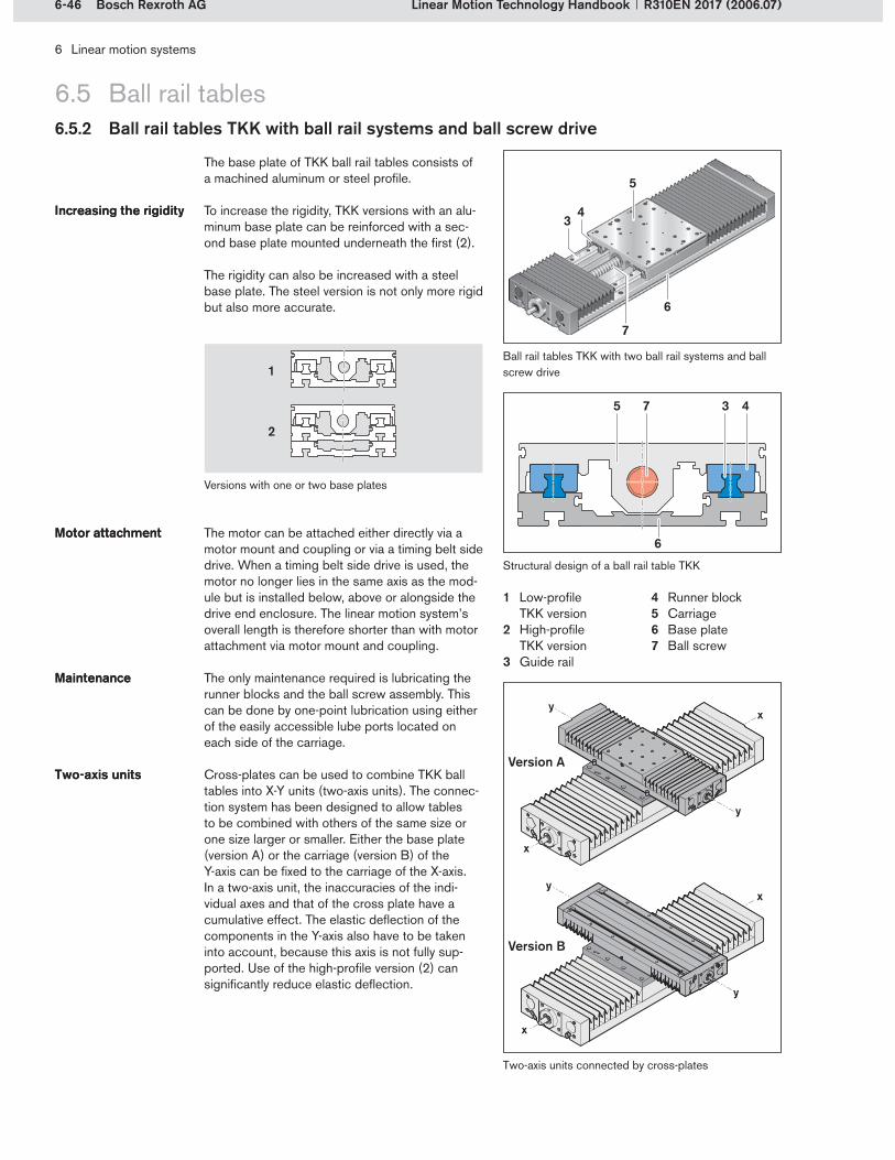
6-46 Bosch Rexroth AG
1
2
7
6
5 3 4
7
6
4
5
3
6 Linear motion systems
Linear Motion Technology Handbook R310EN 2017 (2006.07)
6.5.2 Ball rail tables TKK with ball rail systems and ball screw drive
6.5 Ball rail tables
The base plate of TKK ball rail tables consists of a machined aluminum or steel profile.
To increase the rigidity, TKK versions with an alu-minum base plate can be reinforced with a sec-ond base plate mounted underneath the first (2).
The rigidity can also be increased with a steel base plate. The steel version is not only more rigid but also more accurate.
Increasing the rigidityIncreasing the rigidity
Low-profile TKK versionHigh-profile TKK versionGuide rail
1�
2�
3�
Runner blockCarriageBase plateBall screw
4�5�6�7�
Ball rail tables TKK with two ball rail systems and ball screw drive
Cross-plates can be used to combine TKK ball tables into X-Y units (two-axis units). The connec-tion system has been designed to allow tables to be combined with others of the same size or one size larger or smaller. Either the base plate (version A) or the carriage (version B) of the Y-axis can be fixed to the carriage of the X-axis.In a two-axis unit, the inaccuracies of the indi- vidual axes and that of the cross plate have a cumulative effect. The elastic deflection of the components in the Y-axis also have to be taken into account, because this axis is not fully sup-ported. Use of the high-profile version (2) can significantly reduce elastic deflection.
Two-axis units Two-axis units
Two-axis units connected by cross-plates
The motor can be attached either directly via a motor mount and coupling or via a timing belt side drive. When a timing belt side drive is used, the motor no longer lies in the same axis as the mod-ule but is installed below, above or alongside the drive end enclosure. The linear motion system’s overall length is therefore shorter than with motor attachment via motor mount and coupling.
The only maintenance required is lubricating the runner blocks and the ball screw assembly. This can be done by one-point lubrication using either of the easily accessible lube ports located on each side of the carriage.
Motor attachmentMotor attachment
MaintenanceMaintenance
Structural design of a ball rail table TKK
Version A
Version B
Versions with one or two base plates

6-47Bosch Rexroth AG
4
5 63
1
2
4
3
21
6 Linear motion systems
Linear Motion Technology HandbookR310EN 2017 (2006.07)
6.5.3 Ball rail tables TKL with ball rail systems and linear motor
6.5 Ball rail tables
TKL ball rail tables are particularly suitable for applications requiring high travel speed, high acceleration, and very good positioning accuracy. High-speed positioning tasks or high-acceleration short-stroke movements in quick succession can be performed without difficulty, even in applica-tions with very high demands on positioning accuracy.
Application areas for TKL ball rail tables include:Transfer linesMachining centersHandling systemsTextile machinesPackaging machinesTesting equipment
The high positioning accuracy is due to a precise, distance-coded measuring system. This system is largely insensitive to temperature effects, since the scale is fixed to the base plate.
The runner blocks can be easily lubricated via a central lube port. The linear motor itself is maintenance-free.
Speed Acceleration Positioning accuracy
Speed Acceleration Positioning accuracy
Short strokeShort stroke
ApplicationsApplications
Measuring systemMeasuring system
MaintenanceMaintenance
Secondary element (permanent magnet)Guide railCarriageBase plateRunner blockPrimary element
1�2�3�4�5�6�
Ball rail table TKL with two ball rail systems, linear motor and integrated measurement system
Structural design of a ball rail table TKL

6-48 Bosch Rexroth AG
6 Linear motion systems
Linear Motion Technology Handbook R310EN 2017 (2006.07)
6.6 Linear motion slides6.6.1 System characteristics
The guide unit in linear motion slides consists of shaft-mounted linear bushings that ensure smooth operation and long life. Linear motion slides are an economical solution for many ap-plication areas.
Closed-type linear motion slides are suitable for use as self-supporting units. Here, the two ends of the guideway are connected to the mounting base by means of shaft support blocks. Open-type linear motion slides are fastened to the mounting base via shaft support rails.
Linear bushingsLinear bushings
VersionsVersions
Version Guideway Drive unit Designation Linear motion slides
Closed-type Closed-type Super linear bushing
Without drive
SGO
Ball screwSGK
Open-type
Open-type Super linear bushing
Without drive
SOO
Ball screwSOK
Linear motion slides SGK and SOK with ball screw drive achieve a repeatability of up to 0.005 mm and a positioning accuracy of up to 0.01 mm.Linear motion slides can be delivered in any desired length to suit the customer’s wishes. The maximum length is up to 5.3 m, depending on the size and the drive unit used.The largest size can move loads of up to 1000 kg.High-quality, oil and moisture-resistant, welded bellows on both sides of the carriage protect the internal elements.
FeaturesFeatures
The following table shows all the available ver-sions. More information on linear bushings and shafts can be found in Chapter 4.
OverviewOverview
Closed-type linear motion slide SGK with ball screw drive
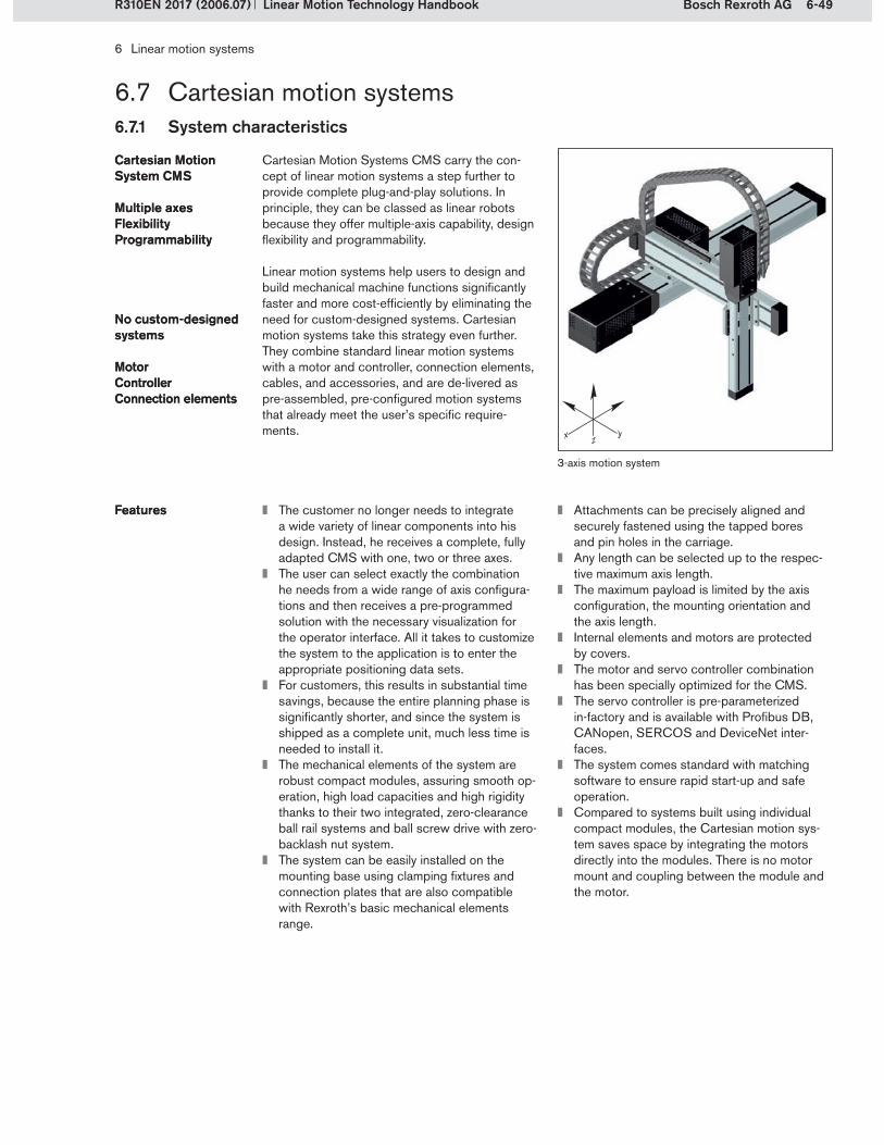
6-49Bosch Rexroth AG
6 Linear motion systems
Linear Motion Technology HandbookR310EN 2017 (2006.07)
6.7.1 System characteristics
6.7 Cartesian motion systems
Cartesian Motion Systems CMS carry the con-cept of linear motion systems a step further to provide complete plug-and-play solutions. In principle, they can be classed as linear robots because they offer multiple-axis capability, design flexibility and programmability.
Linear motion systems help users to design and build mechanical machine functions significantly faster and more cost-efficiently by eliminating the need for custom-designed systems. Cartesian motion systems take this strategy even further. They combine standard linear motion systems with a motor and controller, connection elements, cables, and accessories, and are de-livered as pre-assembled, pre-configured motion systems that already meet the user’s specific require-ments.
Cartesian Motion System CMSCartesian Motion System CMS
Multiple axes Flexibility Programmability
Multiple axes Flexibility Programmability
No custom-designed systemsNo custom-designed systems
MotorControllerConnection elements
MotorControllerConnection elements
3-axis motion system
The customer no longer needs to integrate a wide variety of linear components into his design. Instead, he receives a complete, fully adapted CMS with one, two or three axes.The user can select exactly the combination he needs from a wide range of axis configura-tions and then receives a pre-programmed solution with the necessary visualization for the operator interface. All it takes to customize the system to the application is to enter the appropriate positioning data sets.For customers, this results in substantial time savings, because the entire planning phase is significantly shorter, and since the system is shipped as a complete unit, much less time is needed to install it.The mechanical elements of the system are robust compact modules, assuring smooth op-eration, high load capacities and high rigidity thanks to their two integrated, zero-clearance ball rail systems and ball screw drive with zero-backlash nut system.The system can be easily installed on the mounting base using clamping fixtures and connection plates that are also compatible with Rexroth’s basic mechanical elements range.
FeaturesFeatures Attachments can be precisely aligned and securely fastened using the tapped bores and pin holes in the carriage.Any length can be selected up to the respec-tive maximum axis length.The maximum payload is limited by the axis configuration, the mounting orientation and the axis length.Internal elements and motors are protected by covers.The motor and servo controller combination has been specially optimized for the CMS.The servo controller is pre-parameterized in-factory and is available with Profibus DB, CANopen, SERCOS and DeviceNet inter-faces.The system comes standard with matching software to ensure rapid start-up and safe operation.Compared to systems built using individual compact modules, the Cartesian motion sys-tem saves space by integrating the motors directly into the modules. There is no motor mount and coupling between the module and the motor.

6-50 Bosch Rexroth AG
6 Linear motion systems
Linear Motion Technology Handbook R310EN 2017 (2006.07)
6.7 Cartesian motion systems6.7.2 Basic structure of the CMS
CMS Cartesian motion systems are built using linear motion systems from the CKK Compact module series.
They are designed as 1, 2 or 3-axis systems. The Y-axis is always one size smaller than the X-axis, and the Z-axis is one size smaller than the Y-axis.
In Cartesian motion systems CMS, the mecha-nical guide elements and the electric drive, in- cluding the drive amplifier and optional control unit, are integrated into an axis system. The pre-configured system reduces the effort required by the user for project planning, on-site integration and operation.
The compact drive amplifier answers the trend toward applications in increasingly smaller cells, as it is suitable for both central and decentralized installation.
Multi-axis solutions can also be ordered with attractively priced control units.
1, 2 or 3-axis systems1, 2 or 3-axis systems
3-axis system with servo controller for each axis
1-axis system
2-axis system
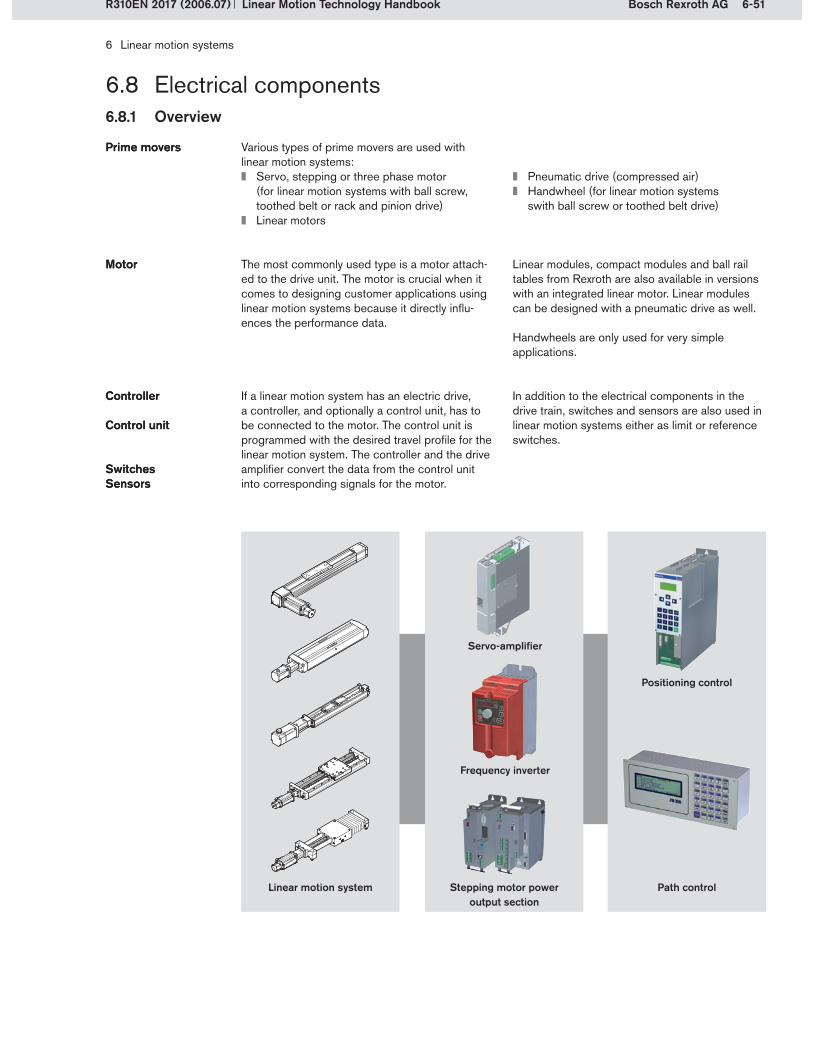
6-51Bosch Rexroth AG
6 Linear motion systems
Linear Motion Technology HandbookR310EN 2017 (2006.07)
6.8.1 Overview
6.8 Electrical components
Various types of prime movers are used with linear motion systems:
Servo, stepping or three phase motor (for linear motion systems with ball screw, toothed belt or rack and pinion drive)Linear motors
Prime moversPrime movers
Pneumatic drive (compressed air)Handwheel (for linear motion systems swith ball screw or toothed belt drive)
The most commonly used type is a motor attach-ed to the drive unit. The motor is crucial when it comes to designing customer applications using linear motion systems because it directly influ-ences the performance data.
MotorMotor Linear modules, compact modules and ball rail tables from Rexroth are also available in versions with an integrated linear motor. Linear modules can be designed with a pneumatic drive as well.
Handwheels are only used for very simple applications.
If a linear motion system has an electric drive, a controller, and optionally a control unit, has to be connected to the motor. The control unit is programmed with the desired travel profile for the linear motion system. The controller and the drive amplifier convert the data from the control unit into corresponding signals for the motor.
ControllerController
Control unitControl unit
In addition to the electrical components in the drive train, switches and sensors are also used in linear motion systems either as limit or reference switches.
SwitchesSensorsSwitchesSensors
Linear motion system
Servo-amplifier
Frequency inverter
Stepping motor power output section
Positioning control
Path control
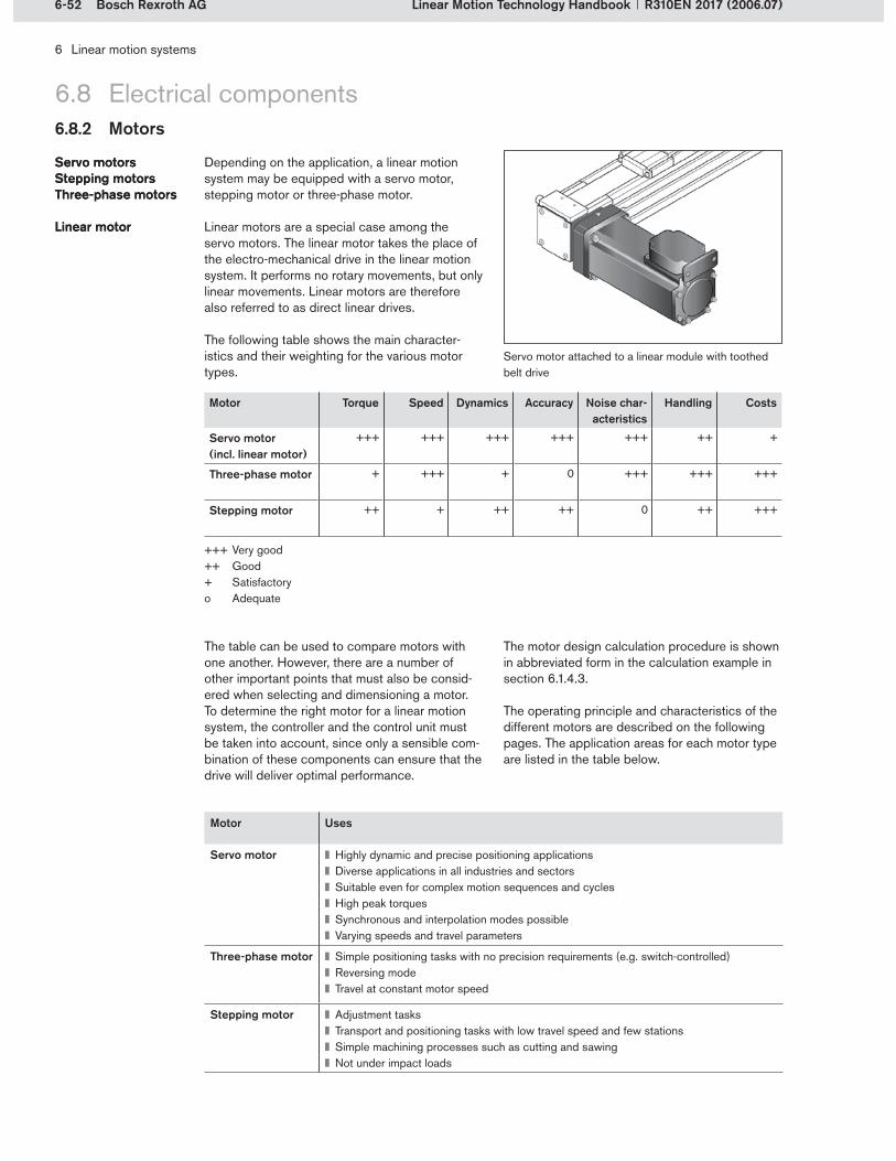
6-52 Bosch Rexroth AG
6 Linear motion systems
Linear Motion Technology Handbook R310EN 2017 (2006.07)
6.8 Electrical components6.8.2 Motors
Depending on the application, a linear motion system may be equipped with a servo motor, stepping motor or three-phase motor.
Linear motors are a special case among the servo motors. The linear motor takes the place of the electro-mechanical drive in the linear motion system. It performs no rotary movements, but only linear movements. Linear motors are therefore also referred to as direct linear drives.
Servo motors Stepping motors Three-phase motors
Linear motor
Servo motors Stepping motors Three-phase motors
Linear motor
Motor Torque Speed Dynamics Accuracy Noise char-acteristics
Handling Costs
Servo motor (incl. linear motor)
+++ +++ +++ +++ +++ ++ +
Three-phase motor + +++ + 0 +++ +++ +++
Stepping motor ++ + ++ ++ 0 ++ +++
The table can be used to compare motors with one another. However, there are a number of other important points that must also be consid-ered when selecting and dimensioning a motor. To determine the right motor for a linear motion system, the controller and the control unit must be taken into account, since only a sensible com-bination of these components can ensure that the drive will deliver optimal performance.
The motor design calculation procedure is shown in abbreviated form in the calculation example in section 6.1.4.3.
The operating principle and characteristics of the different motors are described on the following pages. The application areas for each motor type are listed in the table below.
Motor Uses
Servo motor Highly dynamic and precise positioning applicationsDiverse applications in all industries and sectorsSuitable even for complex motion sequences and cyclesHigh peak torquesSynchronous and interpolation modes possibleVarying speeds and travel parameters
Three-phase motor Simple positioning tasks with no precision requirements (e.g. switch-controlled)Reversing modeTravel at constant motor speed
Stepping motor Adjustment tasksTransport and positioning tasks with low travel speed and few stationsSimple machining processes such as cutting and sawingNot under impact loads
Servo motor attached to a linear module with toothed belt drive
The following table shows the main character-istics and their weighting for the various motor types.
+++ Very good++ Good+ Satisfactoryo Adequate
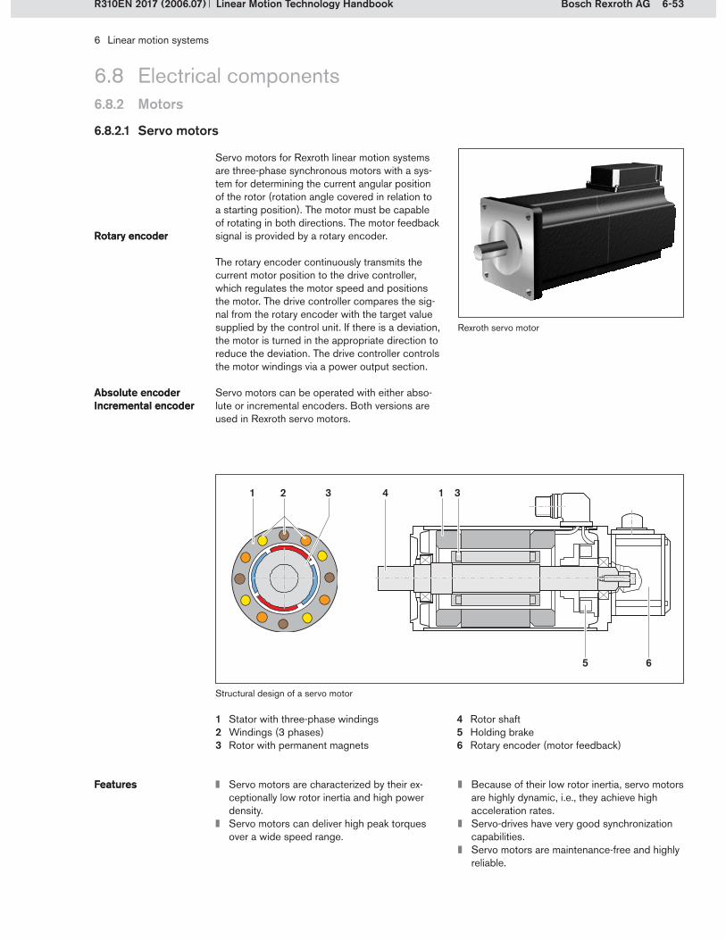
6-53Bosch Rexroth AG
4
5
1 2 3 1 3
6
6 Linear motion systems
Linear Motion Technology HandbookR310EN 2017 (2006.07)
6.8 Electrical components6.8.2 Motors
6.8.2.1 Servo motors
Servo motors for Rexroth linear motion systems are three-phase synchronous motors with a sys-tem for determining the current angular position of the rotor (rotation angle covered in relation to a starting position). The motor must be capable of rotating in both directions. The motor feedback signal is provided by a rotary encoder.
The rotary encoder continuously transmits the current motor position to the drive controller, which regulates the motor speed and positions the motor. The drive controller compares the sig-nal from the rotary encoder with the target value supplied by the control unit. If there is a deviation, the motor is turned in the appropriate direction to reduce the deviation. The drive controller controls the motor windings via a power output section.
Servo motors can be operated with either abso-lute or incremental encoders. Both versions are used in Rexroth servo motors.
Rotary encoderRotary encoder
Absolute encoderIncremental encoderAbsolute encoderIncremental encoder
Structural design of a servo motor
Stator with three-phase windingsWindings (3 phases)Rotor with permanent magnets
1�2�3�
Rotor shaftHolding brakeRotary encoder (motor feedback)
4�5�6�
Servo motors are characterized by their ex-ceptionally low rotor inertia and high power density.Servo motors can deliver high peak torques over a wide speed range.
FeaturesFeatures Because of their low rotor inertia, servo motors are highly dynamic, i.e., they achieve high acceleration rates.Servo-drives have very good synchronization capabilities.Servo motors are maintenance-free and highly reliable.
Rexroth servo motor
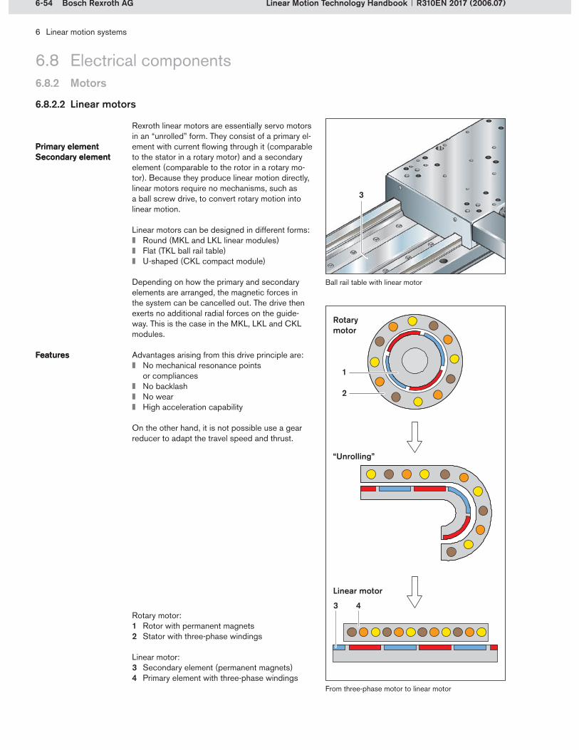
6-54 Bosch Rexroth AG
1
2
3 4
3
6 Linear motion systems
Linear Motion Technology Handbook R310EN 2017 (2006.07)
6.8 Electrical components6.8.2 Motors
6.8.2.2 Linear motors
Rexroth linear motors are essentially servo motors in an “unrolled” form. They consist of a primary el-ement with current flowing through it (comparable to the stator in a rotary motor) and a secondary element (comparable to the rotor in a rotary mo-tor). Because they produce linear motion directly, linear motors require no mechanisms, such as a ball screw drive, to convert rotary motion into linear motion.
Linear motors can be designed in different forms:Round (MKL and LKL linear modules)Flat (TKL ball rail table)U-shaped (CKL compact module)
Depending on how the primary and secondary elements are arranged, the magnetic forces in the system can be cancelled out. The drive then exerts no additional radial forces on the guide-way. This is the case in the MKL, LKL and CKL modules.
Advantages arising from this drive principle are:No mechanical resonance points or compliances No backlashNo wearHigh acceleration capability
On the other hand, it is not possible use a gear reducer to adapt the travel speed and thrust.
Primary element Secondary elementPrimary element Secondary element
FeaturesFeatures
From three-phase motor to linear motor
Ball rail table with linear motor
Rotary motor
Linear motor
“Unrolling”
Rotary motor:Rotor with permanent magnetsStator with three-phase windings
1�2�
Secondary element (permanent magnets)Primary element with three-phase windings
3�4�
Linear motor:

6-55Bosch Rexroth AG
6 Linear motion systems
Linear Motion Technology HandbookR310EN 2017 (2006.07)
6.8.2.3 Three-phase motors
The three-phase motors used in Rexroth linear motion systems are asynchronous three-phase motors. They are used as drives in countless ap-plications. Their rugged design has been proven a million times over and they are extremely easy to put into operation. Because of these good characteristics, this motor type has been stan-dardized internationally and is produced in large quantities throughout the world.
RuggedRugged
6.8 Electrical components6.8.2 Motors
Three-phase gear motor from SEW-EURODRIVE
Three-phase motors are relatively easy to control and commission.
Because of their high rotor inertia, the dynamic performance tends to be on the poor side.Three-phase motors are maintenance-free and highly reliable.They generate very little noise.Motor-gear reducer combinations (three-phase gear motors) are available with spur, worm or bevel gearing.
FeaturesFeatures
6.8.2.4 Stepping motors
Stepping motors are economical, rugged drives. They execute precise rotary movements in steps, as commanded by a positioning control. Stepping motors convert electrical pulses into corresponding analog angles or travel steps, or convert a pulse frequency into a feed value. The motor transmits the travel or speed information coming from the control system directly to the driven system. It does not supply any feedback to the control system. Because stepping motors (provided that they are not overloaded) precisely follow the externally applied field, they can be op-erated without any position feedback sensors, i.e. without rotary encoders. Therefore, unlike servo motors, which always require a closed-loop posi-tion control, stepping motors can be operated in open-loop control.
EconomicalRuggedEconomicalRugged
Stepping motor from Berger Lahr
In stepping motors, the actual position is not monitored. Nevertheless, a high level of precision is possible, if they are dimensioned correctly.Because of their low rotor inertia, stepping motors deliver good dynamic performance, i.e. they can achieve high acceleration rates.Stepping motors are maintenance-free and highly reliable.
FeaturesFeatures Stepping motors can be put into operation quickly and easily, because no control param-eters need to be set.The torque begins to drop off even at speeds less than 1000 min–1 . For high rotary speeds, the torque drop-off must therefore be taken into account.

6-56 Bosch Rexroth AG
2
1
3
6
10
4
5
987
9 8 7
6 Linear motion systems
Linear Motion Technology Handbook R310EN 2017 (2006.07)
6.8 Electrical components6.8.3 Controllers and control systems
The control system for a linear motion system is programmed with individual positions or with a path including the speeds to be traveled and the accelerations. The commands from the control system are then converted by a drive controller into corresponding signals for the motor. The controller simultaneously monitors the motor’s operation.
Depending on the application, a servo, three-phase or stepping motor may be used. The open and closed loop control technology must be adapted to the chosen motor.
Additional sensors and actuators may have to be installed to control and monitor the motor (see section 6.8.4).
ControllersControllers
Adaptation to the motorAdaptation to the motor
SensorsActuatorsSensorsActuators
Positioning controlPath controlControllerThree-phase motorFrequency inverter (regulator)
1�2�3�4�5�
PLC (control system)Limit switchCreep mode cutoff switchRapid traverse cutoff switchLinear module
6�7�8�9�10�
Linear motion system with sensors, control system, controller and three-phase motor
Control components

6-57Bosch Rexroth AG
6 Linear motion systems
Linear Motion Technology HandbookR310EN 2017 (2006.07)
6.8 Electrical components6.8.3 Controllers and control systems
Control signal
Fieldbus
Digital inputs and outputs
Analog signal
Stepping motor signals
Drive amplifier
Servo controller
Drive
Servo motor
Linear motor
6.8.3.1 Servo controllers
Analog interface The servo controller receives analog ±10V speed command values from an NC control system. The servo controller in turn transmits incremental or absolute actual position values back to the NC control system, thus closing the position control loop.
Stepping motor interface The servo controller operates in position loop mode with stepping motor emulation. The position command values are transmitted incrementally from the control system to the controller.
Positioning interface Up to 64 positioning sets are stored in the servo controller. The drive operates in position-controlled mode and travels to the target posi-tion, following the values defined in the posi-tioning sets. The positioning sets are selected and triggered by means of digital PLC inputs. The drive status is signaled back to the master PLC system via digital PLC outputs.
Interfaces and bus systemsInterfaces and bus systems
Rexroth’s compact controllers contain all the necessary supply and control electronics. Stan-dardized interfaces enable connection to various control systems and permit different operating modes.
To allow communication between the control sys-tem and the controller, different computer cards with specific computing capabilities are available for all versions.
SERCOS drive bus The SERCOS interface is an internationally standardized real time communications system in which serial data is transmitted via a noise-immune, fiber optic ring. Digital command and actual values are exchanged between the servo controller and the CNC control system in cycles at precisely equal time intervals.
Standardized fieldbuses When a standardized serial fieldbus interface is used for communication, the servo controller receives digital command values from a control system. In turn, the servo controller transmits status and diagnostic data in digital data pack-ets back to the control system. The following fieldbus interfaces are available:– Profibus DP– Interbus-S– CANopen– DeviceNet
In addition to converting the control signals into commands for the motor, the controller moni-tors whether the target position (signaled by the control system) agrees with the actual position of the rotary encoder on the motor and adjusts this if necessary.
Target positionActual positionTarget positionActual position

6-58 Bosch Rexroth AG
6 Linear motion systems
Linear Motion Technology Handbook R310EN 2017 (2006.07)
6.8 Electrical components6.8.3 Controllers and control systems
6.8.3.2 Frequency inverters
A three-phase (asynchronous) motor’s stator voltage and frequency can be varied infinitely by using a frequency inverter. This turns a standard asynchronous motor into a speed-controlled drive system.
The application areas lie primarily in transport and very simple positioning tasks with few stations and in simple machining processes such as cut-ting and sawing.
Three-phase asynchronous motorThree-phase asynchronous motor
ApplicationsApplications
6.8.3.3 Positioning control
Positioning controls can be used with servo motors and stepping motors. This type of control is used in linear motion systems when motion se-quences are to be determined simply by entering programming sets or when input/output signals are to be monitored and adjusted.
Rexroth’s positioning controls are used to posi-tion up to four axes in a wide variety of applica-tions. They can be combined with the highly dynamic digital servo controllers to produce a powerful and economical control and drive system.
The application areas cover many sectors, such as:
Packaging machinesLinear and X-Y gantriesWoodworking machinesTraveling cuttersFeed and discharge units
Servo motors Stepping motorsServo motors Stepping motors
Positioning of up to four axesPositioning of up to four axes
ApplicationsApplications
Frequency inverter from SEW-EURODRIVE
Rexroth positioning control

6-59Bosch Rexroth AG
6 Linear motion systems
Linear Motion Technology HandbookR310EN 2017 (2006.07)
6.8 Electrical components6.8.3 Controllers and control systems
6.8.3.4 Path control
A path control unit is used with servo motors when a predefined path is to be traveled at prescribed speeds and accelerations. The path can comprise simultaneous movements in several axes.
Special, high-performance, Windows-based con-trol systems from Rexroth can coordinate up to 24 axes with utmost precision and enable parallel operation of up to 16 kinematic configurations in highly demanding tasks.
Typical applications for a path control unit are:Laser processingWater jet cuttingMillingApplication of adhesives
Servo motorsServo motors
24 axes16 kinematic configurations
24 axes16 kinematic configurations
ApplicationsApplications
6.8.3.5 Control cabinet solutions
With a package consisting of individual compo-nents (linear motion system with motor, drive am-plifier, control unit, etc.) the customer has to wire up all the electrical components and commission the system himself.
With a complete solution (linear motion system with motor and control cabinet), all the electri-cal components are already wired up, built into a control cabinet and ready for operation. All the customer needs to do is to start up the system on site.
Package of individual components Package of individual components
Complete solutionComplete solution
Path control unit from SM Motion Control
Linear motion systems Control cabinet

6-60 Bosch Rexroth AG
2
1
6 Linear motion systems
Linear Motion Technology Handbook R310EN 2017 (2006.07)
6.8.4 Switches and sensors
Switches and sensors are used in linear motion systems to fulfill two important functions:
Limit switches (not safety switches in the sense of DIN EN 60204-1 or VDE 0113)Reference switches
Limit switches immediately interrupt the power supply to the drive when the switch is activated. This is to prevent the carriage from traveling further than intended and thereby damaging components in the linear motion system or in the peripherals.
Reference switches inform the controller of the carriage’s position in the linear motion system.Motors with incremental encoders require these switches for commissioning purposes and after every interruption to the power supply, if the linear axis does not have a linear measurement system to provide the position reference. With three-phase motors, proximity switches may be used for positioning. In this case, the switch has a direct effect on the linear motion system’s precision.
Various types of switch can be installed, as stated below, depending on the type of linear motion system.
FunctionsFunctions
Limit switchesLimit switches
Reference switchesReference switches
Linear motion system Switch type
Mechanical switch
Proximity switch
Hall sensor Reed sensor
Linear module – –
Compact module 1) 1)
Precision module – –
Ball rail table – –
Linear motion slide – –
1) Only one size of compact module can be fitted with this type of switch.
6.8 Electrical components
Mechanical switch (1) and proximity switch (2) as limit switches
Hall-type sensor as a reference switch
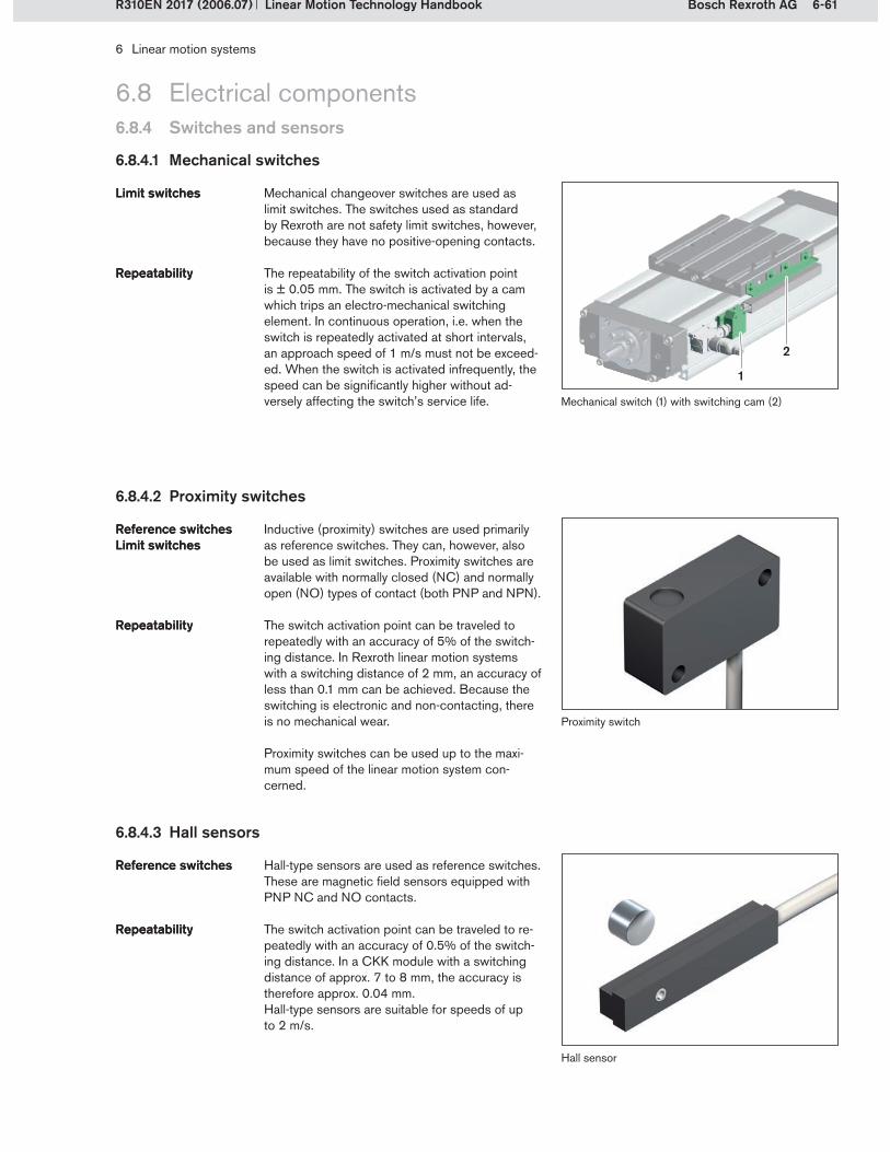
6-61Bosch Rexroth AG
1
2
6 Linear motion systems
Linear Motion Technology HandbookR310EN 2017 (2006.07)
6.8 Electrical components
6.8.4.1 Mechanical switches
Mechanical changeover switches are used as limit switches. The switches used as standard by Rexroth are not safety limit switches, however, because they have no positive-opening contacts.
The repeatability of the switch activation point is ± 0.05 mm. The switch is activated by a cam which trips an electro-mechanical switching element. In continuous operation, i.e. when the switch is repeatedly activated at short intervals, an approach speed of 1 m/s must not be exceed-ed. When the switch is activated infrequently, the speed can be significantly higher without ad-versely affecting the switch’s service life.
Limit switchesLimit switches
RepeatabilityRepeatability
Mechanical switch (1) with switching cam (2)
6.8.4.2 Proximity switches
Inductive (proximity) switches are used primarily as reference switches. They can, however, also be used as limit switches. Proximity switches are available with normally closed (NC) and normally open (NO) types of contact (both PNP and NPN).
The switch activation point can be traveled to repeatedly with an accuracy of 5% of the switch-ing distance. In Rexroth linear motion systems with a switching distance of 2 mm, an accuracy of less than 0.1 mm can be achieved. Because the switching is electronic and non-contacting, there is no mechanical wear.
Proximity switches can be used up to the maxi-mum speed of the linear motion system con-cerned.
Reference switches Limit switchesReference switches Limit switches
RepeatabilityRepeatability
6.8.4.3 Hall sensors
Hall sensor
Hall-type sensors are used as reference switches. These are magnetic field sensors equipped with PNP NC and NO contacts.
The switch activation point can be traveled to re-peatedly with an accuracy of 0.5% of the switch-ing distance. In a CKK module with a switching distance of approx. 7 to 8 mm, the accuracy is therefore approx. 0.04 mm.Hall-type sensors are suitable for speeds of up to 2 m/s.
Reference switchesReference switches
RepeatabilityRepeatability
6.8.4 Switches and sensors
Proximity switch

6-62 Bosch Rexroth AG
5
3
3
2
1
45
6
7
8
6 Linear motion systems
Linear Motion Technology Handbook R310EN 2017 (2006.07)
6.8.4 Switches and sensors
6.8.4.4 Reed sensors
Reed sensor
Sensor, mounted on the frameMagnet, mounted on the carriage
1�2�
Reed sensors are used as limit switches. They are magnetic field sensors and act as changeover switches. Because of their design they have two switching points and are therefore not suitable for use as reference switches.
The repeatability of the switch activation point is approx. 0.1 mm. Reed sensors are suitable for speeds of up to 2 m/s.
Limit switchesLimit switches
RepeatabilityRepeatability
6.8.4.5 Switch mounting arrangements
All linear motion systems are designed so that switches can be attached. Special slots are pro-vided in the frame profiles for mounting of the switches. Cable ducts, sockets and plugs are also available for wiring up the switches and connecting them to the controllers.
Either mechanical and proximity switch combina-tions or magnetic field sensor combinations (Hall and Reed sensors) are used.
Most linear motion systems are designed for use with only one of these switch categories. A few modules can be fitted with all of the options.
Slots in the frame profilesSlots in the frame profiles
Cable ducts, sockets and plugsCable ducts, sockets and plugs
6.8 Electrical components
Mechanical switch, switching cam and proximity switch on a CKR compact module
Magnetic field sensor on a CKR compact module
Socket and plugMechanical switchCable duct
3�4�5�
Switching camProximity switchHall or Reed sensor
6�7�8�

7-1Bosch Rexroth AG
7 Appendix
Linear Motion Technology HandbookR310EN 2017 (2006.07)
7.1 Bosch Rexroth AG: The Drive & Control Company7.1.1 A strong partner worldwide
Bosch Rexroth AG, part of the Bosch Group, achieved sales of approximately 4.9 billion Euro in 2006 with over 29,800 employees. Under the brand name of Rexroth the company offers all drive and control technologies – from mechanics, hydraulics and pneumatics through to electronics – along with the related services. The global player, represented in over 80 countries, is a strong partner to over 500,000 customers, supplying them with an extensive range of components and systems for industrial and factory automation as well as mobile applications.
7.1.2 Linear motion and assembly technologies
Linear motion products are used in all areas of automated manufacturing requiring precision move-ment and high load-bearing capacity. Designed as profiled rail systems, linear bushings and shafts, ball screw assemblies or linear modules, they perform crucial functions as interfaces between stationary and moving machine parts. The assembly technologies offered range from basic mechanical elements to modules for manual production systems, transfer systems and modular chain conveyors for trans-porting parts between machine tools in assembly or packaging lines. With its components and systems Rexroth covers the entire spectrum of linear motion and assembly technology applications.
The range also caters to special requirements and demanding applications. Linear bushings, for exam-ple, also come in miniature versions, fulfilling the needs of many machine and system manufacturers for high functionality combined with compact design. Linear motion systems are offered in corrosion-resistant steel versions for applications requiring a high degree of cleanliness and corrosion-resistance, as are commonly found in the food and chemical industries.

7-2 Bosch Rexroth AG
7 Appendix
Linear Motion Technology Handbook R310EN 2017 (2006.07)
Linear bushing guides can be put together from over 1,000 designs and variations to meet all demands and applications, which means that users can select exactly what they require for every task.
Over 1,000 designs and variationsOver 1,000 designs and variations
Linear bushings and shafts
7.1 Bosch Rexroth AG: The Drive & Control Company7.1.2 Linear motion and assembly technologies
7.1.2.1 Linear motion technology
A complete system for linear guides with ball bearings, which provides the user with infinite possibilities for combining guide rails and runner blocks. Ball rail systems are distinguished in all accuracy classes by their high load capacity and high rigidity, making them suitable for almost all tasks demanding precise linear motion.
One rail system – many runner blocksOne rail system – many runner blocks
Roller rail systems make it easy to handle even the heaviest loads with extremely little effort. With high rigidity central to their design principle to meet the needs of powerful machine tools and robots, linear guides with roller bearings are avail-able in various accuracy and preload classes.
Accurate movement of heavy loadsAccurate movement of heavy loads
Roller rail systems
Ball rail systems
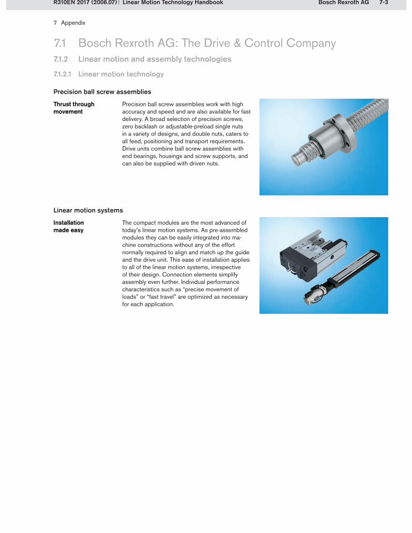
7-3Bosch Rexroth AG
7 Appendix
Linear Motion Technology HandbookR310EN 2017 (2006.07)
7.1 Bosch Rexroth AG: The Drive & Control Company
Precision ball screw assemblies work with high accuracy and speed and are also available for fast delivery. A broad selection of precision screws, zero backlash or adjustable-preload single nuts in a variety of designs, and double nuts, caters to all feed, positioning and transport requirements. Drive units combine ball screw assemblies with end bearings, housings and screw supports, and can also be supplied with driven nuts.
Thrust through movementThrust through movement
The compact modules are the most advanced of today’s linear motion systems. As pre-assembled modules they can be easily integrated into ma-chine constructions without any of the effort normally required to align and match up the guide and the drive unit. This ease of installation applies to all of the linear motion systems, irrespective of their design. Connection elements simplify assembly even further. Individual performance characteristics such as “precise movement of loads” or “fast travel” are optimized as necessary for each application.
Installation made easyInstallation made easy
Precision ball screw assemblies
Linear motion systems
7.1.2 Linear motion and assembly technologies
7.1.2.1 Linear motion technology

7-4 Bosch Rexroth AG
7 Appendix
Linear Motion Technology Handbook R310EN 2017 (2006.07)
7.1 Bosch Rexroth AG: The Drive & Control Company7.1.2 Linear motion and assembly technologies
7.1.2.2 Assembly technology
It doesn’t matter whether you want to build frames, protective enclosures, machine fixtures, workstations, or an entire production line: Our aluminum profile system, with over 100 profile cross sections and the widest range of acces-sories worldwide, will give you absolute freedom during construction, while the strong 10 mm T-slot offers maximum security. Quick and easy assembly ensures your economic success.
A solid basis for productionA solid basis for production
Our manual production systems add efficiency to your production process: with individually adapted, ergonomically designed workstations including material supply, process linking and extensive accessories – available optionally in ESD design. Everything is perfectly matched to each other, and can be combined and configured in minutes with the free planning and calculation software MPScalc.
Flexible and economicalFlexible and economical
Manual production systems
Basic mechanical elements
Shorter and shorter innovation and product cycle times demand production systems that can quick-ly adapt to changing demands. Using Rexroth’s transfer and identification systems you can make economical, future-oriented solutions a reality, whether you have small, precise, or large and heavy products to manufacture.
Quick and efficientQuick and efficient
Material and information flow technology
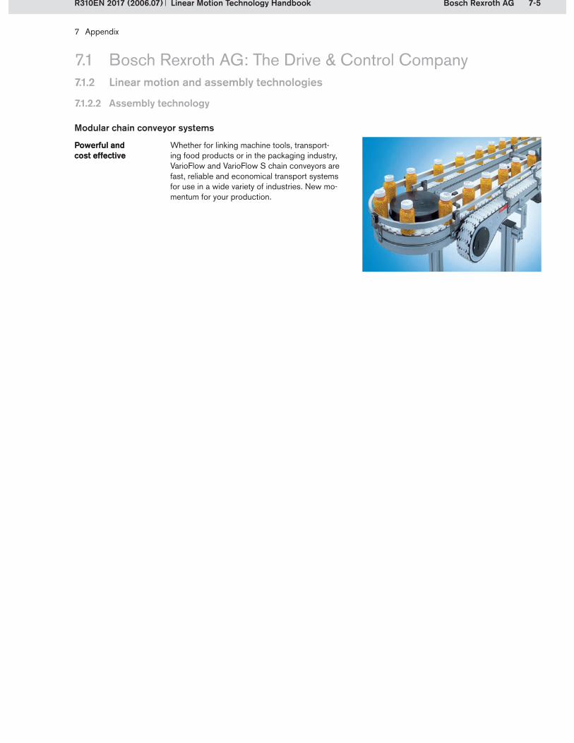
7-5Bosch Rexroth AG
7 Appendix
Linear Motion Technology HandbookR310EN 2017 (2006.07)
7.1.2.2 Assembly technology
Whether for linking machine tools, transport- ing food products or in the packaging industry, VarioFlow and VarioFlow S chain conveyors are fast, reliable and economical transport systems for use in a wide variety of industries. New mo-mentum for your production.
Powerful and cost effectivePowerful and cost effective
Modular chain conveyor systems
7.1 Bosch Rexroth AG: The Drive & Control Company7.1.2 Linear motion and assembly technologies
7-6 Bosch Rexroth AG Linear Motion Technology Handbook R310EN 2017 (2006.07)
7 Appendix
7.2 Glossary
Abrasion: The removal of material by cutting, rubbing or particle impingement.
Actuators: The operative elements in a control circuit. They act as regulators in the control loop, by converting electronic signals (e.g. commands from the control system) into mechani-cal movement (e.g. of solenoid valves).
Circular-arc profile: One of the possible forms of running tracks in rolling bearing guides and ball screw assemblies. In contrast to the gothic arch (see also: gothic profile) the circular-arc profile comprises a single track per side. This produces a 2-point contact between the running tracks and the rolling element.
Conformity: In rolling contact between balls and raceways, conformity of the surfaces is achieved by giving the raceways a circular shape. Conformity increases the contact area and reduces the surface pressure compared with rolling contact without conformity. This also serves to guide the movement of the rolling element.
Consistency: A measure of the plasticity (or stiffness) of grease lubricants. The consistency is determined in accor-dance with ISO 2137 using a penetrometer, which measures the depth of penetration of a standard cone dropped into a grease sample. DIN 51818 permits correlation of the cone penetration depth recorded in accordance with ISO 2137 to a consistency class in accordance with the NLGI classification (National Lubricating Grease Institute).
Critical speed: When a shaft rotates (e.g. the screw of a ball screw assembly), bending vibrations occur. The “critical speed” is the rotary speed that is equivalent to the first bend-ing frequency of the shaft. If the shaft is operated at the critical speed, resonance occurs, which can lead to destruction of the system.
Deformation/deflection: The change in shape of a solid body in response to an applied force. A distinction is made between elastic and plastic deformation. The term elastic deformation or elastic deflection is used to describe a case where the body returns to its original shape once the force ceases to be ap-plied, i.e., there is no permanent deformation. Plastic deforma-tion describes a case where there is lasting deformation once the force ceases to be applied.
Dry lubricant: A solid lubricant incorporated into a lacquer-like matrix of organic or inorganic binder. Dry lubricants are also called lubricating varnishes.
Dynamic load capacity C: The load at which a sufficiently large number of apparently identical bearings will achieve the specified nominal life. In the case of ball screw assemblies and rotary anti-friction bearings, the nominal life is 1 million revolutions. The dynamic load capacity of linear motion guides, such as profiled rail systems and linear bushings and shafts, is based on a nominal life of 100 km.
Dynamic load moments Mt and ML: These are compara-tive dynamic moments which cause a load equivalent to the dynamic load capacity C. A distinction is made between the dynamic torsional load moment Mt and the dynamic longitudinal load moment ML.
Friction coefficient: A dimensionless number that represents the relationship between the friction force and the applied load (normal force).
Gothic profile: One of the possible forms of running tracks in rolling bearing guides and ball screw assemblies. Unlike the circular-arc profile, the running track in the gothic version is composed of two running tracks per side. This produces an ogival form, resulting in four-point contact on the rolling ele-ment.
Hexapod: A spatial positioning machine with 6 legs of variable length and 6 independently controllable drive components. This enables mobility in all 6 degrees of freedom (3 translatory and 3 rotary). Typical applications for hexapods are spindle guides for machine tools or motion mechanisms for driving and flight simulators.
HRC: This abbreviation, followed by a numerical value, is an indication of hardness as measured using the Rockwell C method. Other methods for measuring the hardness of steel are Rockwell A, B and F, Brinell and Vickers. In all hardness testing methods, a defined body, e.g. a diamond cone in the Rockwell C method, is pressed into the sample with a defined test force. The permanent impression in the sample is then measured and serves as a measure of the sample’s hardness.
Incremental encoder: Sensor equipment used to detect changes in the position of linear or rotary components. An incremental encoder can detect travel as well as direction. It contains a track with periodic markings and measures changes in position by scanning the track and counting the number of marks passed. Only relative changes are recorded, not the component’s absolute position. When the encoder is switched on, or after a power failure, a homing cycle to a reference mark must therefore be performed in order to determine the compo-nent’s absolute position. Some incremental measuring systems also have additional features, e.g. distance-coded reference marks, that eliminate the need for a homing cycle. Incremental encoders are used to measure travel, speeds or angles of rota-tion on machine tools, in handling and automation systems, and in measuring and testing equipment.
7-7Bosch Rexroth AGLinear Motion Technology HandbookR310EN 2017 (2006.07)
7 Appendix
Interchangeability: Precision manufacturing makes it possible to combine components of the same size (e.g. runner blocks and guide rails) irrespective of their design, accuracy or pre-load classes.
Lead: Relating to screws or threaded shafts, the lead is the linear distance traveled per revolution of the screw or shaft. In the case of a single thread (single-start screws), this is the distance between two thread crests or two grooves (running tracks).
Limit switches: Switches used to monitor the end position of moving parts. They emit a signal when the component reaches a certain position, usually the beginning or end of a stroke. The signal can be electrical, pneumatic or mechanical. Typical forms of limit switches with electrical signals are roller lever switches or non-contacting switches such as photoelectric sensors and proximity switches.
Linear motor: Electric motor that produces a linear (transla-tory) motion instead of rotary motion. The operating principle of a linear motor corresponds to that of a three-phase motor. The excitation windings (stator), arranged in a circle in a three-phase motor, are arranged in a planar configuration in the case of a linear motor. Here, the rotor is pulled along travel path by the linearly moving magnetic field. Linear motors enable direct linear motion and forces to be produced, i.e. without gears. They are therefore also referred to as direct drives.
Pitching: A rotary movement around the transverse axis (Y-axis) and one of the three basic rotational movements of a body in space.
Positioning accuracy: The positioning accuracy is the maxi-mum deviation between the actual position and the target position, as defined in VDI/DGQ 3441.
Reference switch: Switch used to detect the position of a moved component, e.g. the carriage of a linear motion sys-tem. The switch emits a signal when the component reaches a defined position (reference mark). Reference switches are required for incremental measuring systems or motors with incremental encoders during start-up and after any interruption to the power supply.
Repeatability: Repeatability indicates how precisely a linear motion system positions itself when approaching a position repeatedly from the same direction (unidirectional motion). It is stated as the deviation between the actual position and the target position.
Resonance: The forced vibration of a vibratory system when subjected to periodic external excitation. If the frequency of the forced vibration is close to the natural frequency of the vibratory system, the amplitude of the vibrations can rapidly be-come many times larger than that of the external stimulus. If the damping forces in the system are weak, the amplitude will rise uncontrollably, ultimately resulting in destruction of the system.
Reversing mode: In reversing mode, a component, e.g. the carriage of a linear motion system, is moved alternately for-wards and backwards.
Rolling: A rotary movement around the longitudinal axis (X-axis) and one of the three basic rotational movements of a body in space.
Short stroke: Short-stroke applications are applications in which not all of the rolling elements recirculating within the bearing component arrive in the load-bearing zone during execution of the stroke. The precise definition differs from product to product. The consequences can be premature material fatigue, leading to failure of the guide units. Short-stroke applications must be taken into account when calcu- lating the life expectancy.
Solid lubricant: A substance that alone or in combination with other substances forms an uninterrupted sliding and separating film on metal surfaces. These films are so thin that fits and tol-erances do not have to be altered. Solid lubricants are mostly only required and used for lubrication tasks under extreme con-ditions (e.g. when operating in the mixed friction range). The most well-known are graphite, molybdenum disulfide, various plastics, (e. g. PTFE) and heavy metal sulfide.
Static load capacity C0: The static load which results in a permanent overall deformation of the rolling element and the raceway corresponding to approximately 0.0001 times the rolling element diameter. Deformations of this order have no noticeable effect on the smoothness of travel.
Stick-slip effect: Term used to describe the phenomenon of backsliding between solid bodies being moved against each other, which can occur at low sliding speeds. A rapid motion sequence takes place as a result of adhesion, jamming, sepa-ration and sliding. This leads to vibrations, which can create noises, such as the squealing of a railcar’s wheels when travel-ing round a curve in the track. The problem can be remedied by increasing the sliding speed, lubrication or appropriate selection of materials.
Transmission/transmission ratio: The transmission and con-version of movements, linear and rotary speeds, forces and torques in a geared mechanism. The transmission ratio (also known as reduction ratio) is the ratio between the drive variable and the output variable, e.g. the ratio of input speed to output speed.
7.2 Glossary

7-8 Bosch Rexroth AG Linear Motion Technology Handbook R310EN 2017 (2006.07)
7 Appendix
Viscosity: A measure of a liquid’s resistance to flow when sub-jected to shear stresses. This resistance is due to the liquid’s internal friction.
Worked penetration: Penetration is a method used to mea-sure the consistency of lubricants. In grease lubricants, a cone of defined configuration is allowed to penetrate vertically into the test sample under prescribed conditions (ISO 2137), and the depth of penetration is then measured. A distinction is made between unworked penetration and worked penetration. Worked penetration is the penetration of the cone immediately after the sample has been worked in a container fitted with a plunger by stroking the plunger 60 times within one minute at a temperature of +25 °C.
Yawing: A rotary movement around the vertical axis (Z-axis) and one of the three basic rotational movements of a body in space.
7.2 Glossary

7-9Bosch Rexroth AGLinear Motion Technology HandbookR310EN 2017 (2006.07)
7 Appendix
7.3 Index
0 ... 9 2-point contact . . . . . . . . . . . . . . . . . . . . . . . . . . . . . . . . . . . . .2-134-point contact . . . . . . . . . . . . . . . . . . . . . . . . . . . . . . . . . . . . .2-13
A Absolute accuracy . . . . . . . . . . . . . . . . . . . . . . . . . . . . . . . . . .2-36Absolute measuring systems . . . . . . . . . . . . . . . . . . . . . . . .3-127Accuracy . . . . . . 2-36, 3-18, 3-19, 3-20, 3-21, 3-138, 5-14, 6-13Accuracy classes . . . . . . . . . . . . . . . . . . . .2-36, 3-18, 3-19, 3-20Accuracy of the measuring system . . . . . . . . . . . . . . . . . . .3-138Additional seals . . . . . . . . . . . . . . . . . . . . . . . . . . . . . . . . . . . .2-30Adjoining structure . . . . . . . . . . . . . . . . . . . . . . . . . . . . 3-41, 5-36Adjoining structures and installation tolerances . . . . . . . . . .5-36Adjustable-preload single nut . . . . . . . . . . . . . . . . . . . . . . . . .5-10Analog signal shape . . . . . . . . . . . . . . . . . . . . . . . . . . . . . . .3-136Angular self-adjustment . . . . . . . . . . . . . . . . . . . . . . . . . . . . . .4-27Application parameters . . . . . . . . . . . . . . . . . . . . . . . . . . 4-8, 6-18Average rotary speed . . . . . . . . . . . . . . . . . . . . . . . . . . . . . . .5-23
B Ball contact . . . . . . . . . . . . . . . . . . . . . . . . . . . . . . . . . . . . . . .2-11Ball guides . . . . . . . . . . . . . . . . . . . . . . . . . . . . . . . . . . . . . . . . .2-5Ball nut . . . . . . . . . . . . . . . . . . . . . . . . . . . . . . . . . . . . . . . . . . . .5-4Ball rail systems . . . . . . . . . . . . . . . . . . . . . . . 3-101, 3-107, 3-112Ball rail tables . . . . . . . . . . . . . . . . . . . . . . . . . . . 6-45, 6-46, 6-47Ball rail tables TKK . . . . . . . . . . . . . . . . . . . . . . . . . . . . . . . . .6-46Ball rail tables TKL . . . . . . . . . . . . . . . . . . . . . . . . . . . . . . . . . .6-47Ball recirculation . . . . . . . . . . . . . . . . . . . . . . . . . . . . . . . . . . . .4-5Ball retainer . . . . . . . . . . . . . . . . . . . . . . . . . . . . . . . . . . . . . . . .4-2Ball screw . . . . . . . . . . . 2-9, 2-38, 5-1, 5-2, 5-3, 5-12, 6-6, 6-15Ball screw drive . . . . . . . . . . . . . . . . . . . . 2-8, 2-9, 5-1, 6-6, 6-15Ball size selection . . . . . . . . . . . . . . . . . . . . . . . . . . . . . . . . . .5-10Basic structural design of linear motion systems . . . . . . . . . .6-3Bottom-up fastening of attachments to runner blocks . . . . .3-40Boundary lubrication . . . . . . . . . . . . . . . . . . . . . . . . . . . . . . . .2-32Braking units . . . . . . . . . . . . . . . . . . . . . . . . . . . . . . . . . . . . . .3-99Bus systems . . . . . . . . . . . . . . . . . . . . . . . . . . . . . . . . . . . . . . .6-57Bushing designs . . . . . . . . . . . . . . . . . . . . . . . . . . . . . . . . . . . .4-5
C Calculation example . . . . . . . . . . . . . . . . . . . . . . . . . . 4-23, 5-30Calculations . . . . . . . . . . . . . . . . . . . . . . . . . . . . . . . . . . 3-57, 5-21Cam roller guides . . . . . . . . . . . . . . . . . . . . . . . . . . . . .2-5, 3-122Carriage . . . . . . . . . . . . . . . . . . . . . . . . . . . . . . . . . . . . . . . . . . .6-4Cartesian Motion System CMS . . . . . . . . . . . . . . . . . . . . . . .6-49Characteristic speed . . . . . . . . . . . . . . . . . . . . . . . . . . . . . . . .5-17Chemical effects . . . . . . . . . . . . . . . . . . . . . . . . . . . . . . . . . . .2-23Circular-arc raceway . . . . . . . . . . . . . . . . . . . . . . . . . . . . . . . .2-13CKK . . . . . . . . . . . . . . . . . . . . . . . . . . . . . . . . . . . . . . . . . . . . .6-39CKL . . . . . . . . . . . . . . . . . . . . . . . . . . . . . . . . . . . . . . . . . . . . . .6-41CKR . . . . . . . . . . . . . . . . . . . . . . . . . . . . . . . . . . . . . . . . . . . . .6-40Clamping units . . . . . . . . . . . . . . . . . . . . . . . . . . . . . . . . . . . . .3-99Closed drive unit (AGK) . . . . . . . . . . . . . . . . . . . . . . . . . . . . .5-46Closely spaced runner blocks . . . . . . . . . . . . . . . . . . . . . . . .3-73CMS . . . . . . . . . . . . . . . . . . . . . . . . . . . . . . . . . . . . . . . . . . . . .6-49Combined equivalent load on bearing . . . . . . . . . . . . . 3-11, 3-71Combined load . . . . . . . . . . . . . . . . . . . . . . . . . . . . . . . . . . . .4-21
Compact modules . . . . . . . . . . . . . . . . . . 6-38, 6-39, 6-40, 6-41Compact modules CKK . . . . . . . . . . . . . . . . . . . . . . . . . . . . .6-39Compact modules CKL . . . . . . . . . . . . . . . . . . . . . . . . . . . . .6-41Compact modules CKR . . . . . . . . . . . . . . . . . . . . . . . . . . . . .6-40Composite guide rails . . . . . . . . . . . . . . . . . . . . . . . . . 3-38, 3-39Conditions of use . . . . . . . . . . . . . . . . . . . . . . . . . . . . 2-22, 2-25Connection brackets . . . . . . . . . . . . . . . . . . . . . . . . . . . . . . . .6-37Connection elements . . . . . . . . . . . . . . . . . . . . . . 6-9, 6-37, 6-42Connection plates . . . . . . . . . . . . . . . . . . . . . . . . . . . . . . . . . .6-37Consistency . . . . . . . . . . . . . . . . . . . . . . . . . . . . . . . . . . . . . . .2-33Contact angle . . . . . . . . . . . . . . . . . . . . . . . . . . . . . . . . . . . . . .3-7Contact area . . . . . . . . . . . . . . . . . . . . . . . . . . . . . . . . . . . . . .2-10Contact factor . . . . . . . . . . . . . . . . . . . . . . . . . . . . . . . . . . . . .3-73Contamination . . . . . . . . . . . . . . . . . . . . . . . . . . . . . . . . . . . . .2-22Control cabinet solutions . . . . . . . . . . . . . . . . . . . . . . . . . . . .6-59Control system . . . . . . . . . . . . . . . . . . . . . . . . . . . . . . . . . 2-4, 6-21Control systems . . . . . . . . . . . . . . . . . . . . . . . . . . . . . . . . . . . .6-56Controller . . . . . . . . . . . . . . . . . . . . . . . . . . . . . . . . . . . . . . . . .6-21Controllers . . . . . . . . . . . . . . . . . . . . . . . . . . . . . . . . . . .6-56, 6-57Conversion factors for dynamic load capacities . . . . . . . . . .2-17Coordinate system . . . . . . . . . . . . . . . . . . . . . . . . . . . . . . . . . .3-5Corrosion protection . . . . . . . . . . . . . . . . . . . . . . . . . . . . . . . .3-98Cover . . . . . . . . . . . . . . . . . . . . . . . . . . . . . . . . . . . . . . . . . . . . .6-8Critical speed . . . . . . . . . . . . . . . . . . . . . . . . . . . . . . . . . . . . . .5-27Cycle . . . . . . . . . . . . . . . . . . . . . . . . . . . . . . . . . . . . . . . .2-18, 5-22
D Damage profiles . . . . . . . . . . . . . . . . . . . . . . . . . . . . . . . . . . . .2-26Define the operating conditions . . . . . . . . . . . . . . . . . . . . . . .3-59Defining the requirements . . . . . . . . . . . . . . . . . . . . . . . . . . . .5-21Dependency of nominal life on the direction of loading . . . .3-12Design notes . . . . . . . . . . . . . . . . . . . . . . 3-50, 4-10, 5-36, 6-23Design styles . . . . . . . . . . . . . . . . . . . . . . . . . . . . . . . . . . . . . . .3-4Differential slip . . . . . . . . . . . . . . . . . . . . . . . . . . . . . . . . . . . . .2-14Digital signals . . . . . . . . . . . . . . . . . . . . . . . . . . . . . . . . . . . . .3-137Direct linear drives . . . . . . . . . . . . . . . . . . . . . . . . . . . . . . . . . .6-16Direct measuring systems . . . . . . . . . . . . . . . . . . . . . . . . . . .3-127Direction of loading . . . . . . . . . . . . . . . . . . . . . . . 3-10, 3-12, 4-10Discrete time steps . . . . . . . . . . . . . . . . . . . . . . . . . . . .2-19, 2-20Discrete travel steps . . . . . . . . . . . . . . . . . . . . . . . . . . . . . . . .2-19Distance-coded reference marks . . . . . . . . . . . . . . . . . . . . .3-135Double nut . . . . . . . . . . . . . . . . . . . . . . . . . . . . . . . . . . . 5-11, 5-44Down load . . . . . . . . . . . . . . . . . . . . . . . . . . . . . . . . . . . . . . . .3-16Drag torque variations . . . . . . . . . . . . . . . . . . . . . . . . . . . . . . .5-16Drive . . 2-4, 2-8, 2-9, 3-100, 5-1, 5-29, 5-45, 5-46, 5-48, 5-49,
6-5, 6-6, 6-15, 6-17Drive torque and drive power . . . . . . . . . . . . . . . . . . . . . . . . .5-29Drive unit of a linear motion system . . . . . . . . . . . . . . . . . . . . .6-5Drive unit types . . . . . . . . . . . . . . . . . . . . . . . . . . . . . . . . . . . .6-15Drive units with driven nut . . . . . . . . . . . . . . . . . . . . . . 5-44, 5-48Drive units with driven screw . . . . . . . . . . . . . . . . . . . . . . . . .5-45Dynamic cycle . . . . . . . . . . . . . . . . . . . . . . . . . . . . . . . . . . . . .5-22Dynamic drag torque . . . . . . . . . . . . . . . . . . . . . . . . . . . . . . . .5-16Dynamic load capacity C . . . . . . . . . . . . . . . . . . . 2-16, 3-9, 4-10Dynamic load moments Mt, ML . . . . . . . . . . . . . . . . . . . . . . . . .3-9Dynamic load rating C . . . . . . . . . . . . . . . . . . . . . . . . . . . . . . . .5-9Dynamic load ratio . . . . . . . . . . . . . . . . . . . . . . . . . . . . . . . . . .3-29

7-10 Bosch Rexroth AG Linear Motion Technology Handbook R310EN 2017 (2006.07)
7 Appendix
7.3 Index
E Easy-2-Combine . . . . . . . . . . . . . . . . . . . . . . . . . . . . . . . . . . .6-42Edges . . . . . . . . . . . . . . . . . . . . . . . . . . . . . . . . . . .3-5, 3-42, 3-44Effective equivalent load on bearing . . . . . . . . . . . . . . . . . . .3-74Elastic deflection . . . . . . . . . . . . . . . . . . . . . . . . . . . . . . . . . . .2-12Electrical current . . . . . . . . . . . . . . . . . . . . . . . . . . . . . . . . . . .2-23Electrical drive . . . . . . . . . . . . . . . . . . . . . . . . . . . . . . . . . . . . . .2-8Electromechanical drive . . . . . . . . . . . . . . . . . . . . . . . . . . . . . .2-8Elements of a machine . . . . . . . . . . . . . . . . . . . . . . . . . . . . . . .2-4eLINE ball rail systems . . . . . . . . . . . . . . . . . . . . . . . . . . . . .3-112eLINE linear bushings . . . . . . . . . . . . . . . . . . . . . . . . . . . . . . .4-26eLINE series single nuts . . . . . . . . . . . . . . . . . . . . . . . 5-42, 5-43End bearings . . . . . . . . . . . . . . . . . . . . . . . . . . . . . . . . . .5-8, 5-29End seals . . . . . . . . . . . . . . . . . . . . . . . . . . . . . . . . . . . . . . . . .2-30Entry zone . . . . . . . . . . . . . . . . . . . . . . . . . . . . . . . . . . . . . . . . .3-23Environmental conditions . . . . . . . . . . . . . . . . . . . . . . . . . . . .2-22Equivalent dynamic axial load . . . . . . . . . . . . . . . . . . . . . . . . .5-25Equivalent dynamic load . . . . . . . . . . . . . . . . . . . 2-18, 3-75, 4-19Equivalent dynamic load on bearing . . . . . . . . . 2-18, 3-75, 4-19Equivalent dynamic loading . . . . . . . . . . . . . . . . . . . . . . . . . .3-75Equivalent load on bearing . . . . . . . 2-18, 3-11, 3-71, 3-74, 3-75Equivalent static load . . . . . . . . . . . . . . . . . . . . . . . . . .2-18, 3-79Equivalent static load on bearing . . . . . . . . . . . . . . . . . . . . . .3-79
F FAR drive unit with belt-driven nut . . . . . . . . . . . . . . . . . . . . .5-48Fastening linear motion systems to the mounting base . . . .6-25Five degrees of freedom . . . . . . . . . . . . . . . . . . . . . . . . . . . . .3-21Flanged nuts. . . . . . . . . . . . . . . . . . . . . . . . . . . . . . . . . . . . . . . .5-6Flow of forces . . . . . . . . . . . . . . . . . . . . . . . . . . . . . . . . . . . . . .5-9Fluidostatic sliding guides . . . . . . . . . . . . . . . . . . . . . . . . . . . .2-5Force flow . . . . . . . . . . . . . . . . . . . . . . . . . . . . . . . . . . . . . . . . .3-10Frame . . . . . . . . . . . . . . . . . . . . . . . . . . . . . . . . . . . . . . . . . 2-4, 6-4Frequency inverters . . . . . . . . . . . . . . . . . . . . . . . . . . . . . . . . .6-58Friction . . . . . . . . . . . . . . . . . . . . . . . . . . . 2-14, 2-29, 3-24, 3-25Friction coefficient . . . . . . . . . . . . . . . . . . . . . . . . . . . . .2-14, 2-29Friction force . . . . . . . . . . . . . . . . . . . . . . . . . . . . . . . . . . . . . .2-29Friction of the seals . . . . . . . . . . . . . . . . . . . . . . . . . . . . . . . . .3-25Front lube units . . . . . . . . . . . . . . . . . . . . . . . . . . . . . . . . . . . .3-95Full lubrication . . . . . . . . . . . . . . . . . . . . . . . . . . . . . . . . . . . . .2-32Function of seals . . . . . . . . . . . . . . . . . . . . . . . . . . . . . . . . . . .2-30Function of the measuring sensor and scale. . . . . . . . . . . .3-134Function of the reference sensor and reference marks . . .3-135
G Gear units . . . . . . . . . . . . . . . . . . . . . . . . . . . . . . . . . . . . . . . . . .6-7Gothic-arch raceway . . . . . . . . . . . . . . . . . . . . . . . . . . . . . . . .2-13Grease lubricants . . . . . . . . . . . . . . . . . . . . . . . . . . . . . . . . . .2-33Guide rail mounting . . . . . . . . . . . . . . . . . . . . . . . . . . . . . . . . .3-34Guide to choosing the right product . . . . . . . . . . . . . . . . . . .5-19Guides . . . . . . . . . . . . . . . . . . . . . . . . . 2-1, 2-4, 2-5, 3-122, 4-33
H Hall sensors . . . . . . . . . . . . . . . . . . . . . . . . . . . . . . . . . . . . . . .6-61Height accuracy . . . . . . . . . . . . . . . . . . . . . . . . . . . . . . . . . . . .3-18High precision versions . . . . . . . . . . . . . . . . . . . . . . . . . . . . . .3-22Holding rings . . . . . . . . . . . . . . . . . . . . . . . . . . . . . . . . . . . . . . .4-2
Humidity . . . . . . . . . . . . . . . . . . . . . . . . . . . . . . . . . . . . . . . . . .2-23Hydraulic drive . . . . . . . . . . . . . . . . . . . . . . . . . . . . . . . . . . . . . .2-8Hydrodynamic sliding guides . . . . . . . . . . . . . . . . . . . . . . . . . .2-5
I Impacts and overloading . . . . . . . . . . . . . . . . . . . . . . . . . . . . .2-24In-service lubrication . . . . . . . . . . . . . . . . . . . . . . . . . . .2-35, 4-14Incremental measuring systems . . . . . . . . . . . . . . . . . . . . . .3-127Indirect measuring systems . . . . . . . . . . . . . . . . . . . . . . . . .3-127Inductive measuring systems . . . . . . . . . . . . . . . . . . . . . . . .3-128Inductive switches . . . . . . . . . . . . . . . . . . . . . . . . . . . . . . . . . .6-61Initial lubrication . . . . . . . . . . . . . . . . . . . . . . . . . . . . . . . . . . . .2-35Installation conditions . . . . . . . . . . . . . . . . . . . . . . . . . . . . . . .2-25Installation in customer-built housings . . . . . . . . . . . . . . . . . .4-13Installation tolerances . . . . . . . . . . . . . . . . . . . . 3-50, 5-36, 5-37Integrated measuring system . . . . . . . . . . . . . . . . . . . . . . . .3-127Interfaces . . . . . . . . . . . . . . . . . . . . . . . . . . . . . . . . . . . . . . . . .6-57Interpolation . . . . . . . . . . . . . . . . . . . . . . . . . . . . . . . . . . . . . .3-136
L Lateral retention . . . . . . . . . . . . . . . . . . . . . . . . . . . . . . 3-43, 3-44Layout of reference edges and lateral retention elements . .3-44Life expectancy . . . . . . . . . . . . . . . . . . . . . . . . . .2-16, 3-78, 5-23Lift-off force . . . . . . . . . . . . . . . . . . . . . . . . . . . . . . . . . . . . . . .3-74Lift-off load . . . . . . . . . . . . . . . . . . . . . . . . . . . . . . . . . . . . . . . .3-16Limit switches. . . . . . . . . . . . . . . . . . . . . . . . . . . . . . . . . . . . . .6-60Line contact in the case of rollers . . . . . . . . . . . . . . . . . . . . .2-10Linear bushing characteristics . . . . . . . . . . . . . . . . . . . . . . . . .4-7Linear bushing technical data . . . . . . . . . . . . . . . . . . . . . . . . . .4-7Linear bushings . . . .2-37, 4-1, 4-4, 4-26, 4-27, 4-29, 4-31, 4-33Linear bushings and shafts . . . . . . . . . . . . . . . . . . . . . . . 2-37, 4-1Linear guides . . . . . . . . . . . . . . . . . . . . . . . . . . . . . . . . . .2-5, 4-33Linear modules . . . . . . . . . . . . . . . . . . . . . . . . . . . . . . . . . . . . .6-31Linear modules MKK . . . . . . . . . . . . . . . . . . . . . . . . . . . . . . . .6-32Linear modules MKL and LKL . . . . . . . . . . . . . . . . . . . . . . . .6-36Linear modules MKP . . . . . . . . . . . . . . . . . . . . . . . . . . . . . . . .6-35Linear modules MKR/MKZ . . . . . . . . . . . . . . . . . . . . . . . . . . .6-34Linear modules MKR/MLR . . . . . . . . . . . . . . . . . . . . . . . . . . .6-33Linear motion . . . . . . . . . . . . 2-1, 2-38, 6-1, 6-3, 6-5, 6-25, 6-48Linear motion slides . . . . . . . . . . . . . . . . . . . . . . . . . . . . . . . . .6-48Linear motion systems . . . . . . . . . . . . . . . . . . 2-38, 6-1, 6-3, 6-25Linear motor . . . . . . . . . . . . . . . . . . . . . . . . . . . . . .6-6, 6-16, 6-54Linear sets . . . . . . . . . . . . . . . . . . . . . . . . . . . . . . . . . . . . . . . .4-35Liquid grease . . . . . . . . . . . . . . . . . . . . . . . . . . . . . . . . . . . . . .2-33LKL . . . . . . . . . . . . . . . . . . . . . . . . . . . . . . . . . . . . . . . . . . . . . .6-36Load capacities . . . . . . . . . . . . . . . . . . . . . . . . . . . . . . . 2-17, 6-12Load capacity . . . . . . . . . . . . . . . . . . . . . . . . . 2-16, 3-9, 4-10, 5-9Load on the screw connections of guide rails . . . . . . . . . . .3-38Load ratings . . . . . . . . . . . . . . . . . . . . . . . . . . . . . . . . . . . . . . . .5-9Load-dependent in-service lubrication . . . . . . . . . . . . . . . . . .4-14Load-bearing capability . . . . . . . . . . . . . . . . . . . . . . . . . . . . . . .3-9Logarithmic profile . . . . . . . . . . . . . . . . . . . . . . . . . . . . . . . . . .2-11Lubricant friction . . . . . . . . . . . . . . . . . . . . . . . . . . . . . . . . . . .3-25Lubricants . . . . . . . . . . . . . . . . . . . . . . . . . . . . . . . . . . . 2-33, 2-34Lubrication . 2-24, 2-31, 2-32, 2-35, 3-94, 4-14, 4-15, 5-18, 6-4Lubrication intervals . . . . . . . . . . . . . . . . . . . . . . . . . . . .2-35, 4-15

7-11Bosch Rexroth AGLinear Motion Technology HandbookR310EN 2017 (2006.07)
7 Appendix
7.3 Index
M Magnetic position measuring systems . . . . . . . . . . . 3-127, 3-128Manual calculation . . . . . . . . . . . . . . . . . . . . . . . . . . . . . . . . . .3-57Maximum linear speed . . . . . . . . . . . . . . . . . . . . . . . . . . . . . . .5-17Measuring systems . . . . . . . . . . . . . . . . . . . . . . 3-127, 3-128, 6-8Mechanical efficiency . . . . . . . . . . . . . . . . . . . . . . . . . . . . . . .5-17Mechanical switches . . . . . . . . . . . . . . . . . . . . . . . . . . .6-60, 6-61Metalworking fluids . . . . . . . . . . . . . . . . . . . . . . . . . . . . . . . . .2-23MHS drive unit with hollow shaft motor. . . . . . . . . . . . . . . . .5-49Miniature ball rail systems . . . . . . . . . . . . . . . . . . . . . . . . . . .3-107Miniature series single nuts . . . . . . . . . . . . . . . . . . . . . 5-41, 5-42MKK . . . . . . . . . . . . . . . . . . . . . . . . . . . . . . . . . . . . . . . . . . . . .6-32MKL . . . . . . . . . . . . . . . . . . . . . . . . . . . . . . . . . . . . . . . . . . . . .6-36MKP . . . . . . . . . . . . . . . . . . . . . . . . . . . . . . . . . . . . . . . . . . . . .6-35MKR . . . . . . . . . . . . . . . . . . . . . . . . . . . . . . . . . . . . . . . 6-33, 6-34MKZ . . . . . . . . . . . . . . . . . . . . . . . . . . . . . . . . . . . . . . . . . . . . .6-34MLR . . . . . . . . . . . . . . . . . . . . . . . . . . . . . . . . . . . . . . . . . . . . .6-33Modified life expectancy . . . . . . . . . . . . . . . . . . . . . . . .2-16, 3-78Moments . . . . . . . . . . . . . . . . . . . . . . . . . . . . . . . . . . . . . . 3-9, 6-12Motor. . . . . . . . . . . . . . . . . . . . . . . . . . 5-49, 6-7, 6-16, 6-21, 6-52Motor, controller and control system . . . . . . . . . . . . . . . . . . .6-21Mounting instructions . . . . . . . . . . . . . . . . . . . . . . . . . . . . . . .5-39Mounting of V-guide rail using pressure pieces . . . . . . . . . .3-36Mounting orientation of the profiled rail guide . . . . . . . . . . .3-34Mounting the guide rail from above . . . . . . . . . . . . . . . . . . . .3-34Mounting the guide rail from below . . . . . . . . . . . . . . . . . . . .3-35Mounting tool . . . . . . . . . . . . . . . . . . . . . . . . . . . . . . . . . . . . . .4-13
N NLGI grades . . . . . . . . . . . . . . . . . . . . . . . . . . . . . . . . . . . . . . .2-33Nominal contact angle . . . . . . . . . . . . . . . . . . . . . . . . . . . . . . .3-7Nominal life . . . . . . . . . . 2-15, 2-16, 3-12, 3-76, 3-77, 4-16, 5-26Nominal life calculation limits . . . . . . . . . . . . . . . . . . . . . . . . .3-77Nominal life in operating hours . . . . . . . . . . . . . . . . . . . . . . . .3-76Normal conditions of use . . . . . . . . . . . . . . . . . . . . . . . . . . . .2-25Number of runner blocks and guide rails . . . . . . . . . . . . . . . .3-33Nut body . . . . . . . . . . . . . . . . . . . . . . . . . . . . . . . . . . . . . . . . . . .5-6Nut forms . . . . . . . . . . . . . . . . . . . . . . . . . . . . . . . . . . . . . . . . . .5-6Nut housings . . . . . . . . . . . . . . . . . . . . . . . . . . . . . . . . . . . . . . .5-8
O Oil lubricants . . . . . . . . . . . . . . . . . . . . . . . . . . . . . . . . 2-33, 2-34Open drive units (AOK) . . . . . . . . . . . . . . . . . . . . . . . . . . . . .5-45Operating conditions . . . . . . . . . . . . . . . . . . . . . . . . . . 2-24, 3-59Operating principle . . . . . . . . . . . . . . . . . . . . . . . . . . . . . . . . . .5-2Optical position measuring systems . . . . . . . . . . . . . . . . . .3-128Options for closing mounting holes . . . . . . . . . . . . . . . . . . . .3-35Orientation of the direction . . . . . . . . . . . . . . . . . . . . . . . . . . .4-10
P Parallelism . . . . . . . . . . . . . . . . . . . . . . . . . . . . . .3-18, 3-19, 3-53Parallelism offset of mounted rails . . . . . . . . . . . . . . . . . . . . .3-53Parallelism offset of the rail guide in service . . . . . . . . . . . . .3-19Partial lubrication . . . . . . . . . . . . . . . . . . . . . . . . . . . . . . . . . . .2-32Path control . . . . . . . . . . . . . . . . . . . . . . . . . . . . . . . . . . . . . . .6-59Permissible axial load on screw . . . . . . . . . . . . . . . . . . . . . . .5-28Permissible side loads . . . . . . . . . . . . . . . . . . . . . . . . . . . . . . .3-41
Permissible vertical offset in the longitudinal direction S2. .3-52Permissible vertical offset in the transverse direction S1 . .3-51Pinning of runner blocks . . . . . . . . . . . . . . . . . . . . . . . . . . . . .3-40Pneumatic drive . . . . . . . . . . . . . . . . . . . . . . . . . . . . . . . . 2-8, 6-17Point contact in the case of balls . . . . . . . . . . . . . . . . . . . . . .2-10Positioning accuracy . . . . . . . . . . . . . . . . . . . . . . . . . . . . . . . .2-36Positioning contro . . . . . . . . . . . . . . . . . . . . . . . . . . . . . . . . . .6-58Pre-selection . . . . . . . . . . . . . . . . . . . . . . . . . . . . . . . . 3-26, 5-20Precision ball screw assemblies . . . . . . . . . . . . . . . . . . . . . .2-38Precision manufacturing . . . . . . . . . . . . . . . . . . . . . . . . . . . . .3-20Precision modules . . . . . . . . . . . . . . . . . . . . . . . . . . . . . . . . . .6-43Precision steel shafts . . . . . . . . . . . . . . . . . . . . . . . . . . .4-3, 4-37Preload . . . . . . . . . . . . . . . . . . 2-28, 3-14, 3-15, 3-74, 5-10, 5-24Preload and rigidity . . . . . . . . . . . . . . . . . . . . . . . . . . . . . . . . .2-28Preload classes . . . . . . . . . . . . . . . . . . . . . . . . . . . . . . . . . . . .3-15Preload force . . . . . . . . . . . . . . . . . . . . . . . . . . . . . . . . . . . . . .3-74Preloading . . . . . . . . . . . . . . . . . . . . . . . . . . . . . . . . . . . 4-12, 5-10Preloading by ball size selection . . . . . . . . . . . . . . . . . . . . . .5-10Preservative oils . . . . . . . . . . . . . . . . . . . . . . . . . . . . . . . . . . . .2-34Press-fitting the V-guide rail into mounting base . . . . . . . . .3-36Prinziples . . . . . . . . . . . . . . . . . . . . . . . . . . . . . . . . . . . . . . . . . .2-1Probability of survival . . . . . . . . . . . . . . . . . . . . . . . . . . . . . . . .2-15Procedure for manual calculations . . . . . . . . . . . . . . . . . . . . .3-57Product pre-selection . . . . . . . . . . . . . . . . . . . . .3-26, 5-19, 5-20Product selection . . . . . . . . . . . . . . . .3-26, 3-30, 4-6, 5-20, 6-18Product selection procedure . . . . . . . . . . . . . . . . . . . 3-30, 5-20Profiled rail system layout . . . . . . . . . . . . . . . . . . . . . . . . . . . .3-33Profiled rail systems . . . . . . . . . . . . . . . . . . . . . . . . . 2-1, 2-37, 3-1Proximity switches . . . . . . . . . . . . . . . . . . . . . . . . . . . . . . . . . .6-61Pure torque load . . . . . . . . . . . . . . . . . . . . . . . . . . . . . . . . . . .4-21
R Raceways . . . . . . . . . . . . . . . . . . . . . . . . . . . . . . . . . . . . . . . . .2-13Rack and pinion . . . . . . . . . . . . . . . . . . . . . . . . . .3-100, 6-6, 6-16Rack and pinion drive . . . . . . . . . . . . . . . . . . . . . . . . . .3-100, 6-6Radial clearance . . . . . . . . . . . . . . . . . . . . . . . . . . . . . . . . . . .4-12Recirculation . . . . . . . . . . . . . . . . . . . . . . . . . . . . . . . 2-7, 4-5, 5-5Recirculation systems . . . . . . . . . . . . . . . . . . . . . . . . . . . . . . . .5-5Reed sensors . . . . . . . . . . . . . . . . . . . . . . . . . . . . . . . . . . . . . .6-62Reference edges . . . . . . . . . . . . . . . . . . . . . . . . . . . . . 3-42, 3-44Reference marks . . . . . . . . . . . . . . . . . . . . . . . . . . . . 3-131, 3-135Reference surfaces . . . . . . . . . . . . . . . . . . . . . . . . . . . . . . . . . .3-5Reference switches . . . . . . . . . . . . . . . . . . . . . . . . . . . . . . . . .6-60Repeatability . . . . . . . . . . . . . . . . . . . . . . . . . . . . . . . . .2-36, 3-137Resistance to movement . . . . . . . . . . . . . . . . . . . . . . . . . . . . .2-30Resolution. . . . . . . . . . . . . . . . . . . . . . . . . . . . . . . . . . . . . . . .3-136Resulting load . . . . . . . . . . . . . . . . . . . . . . . . . . . . . . . . . . . . .4-19Retention . . . . . . . . . . . . . . . . . . . . . . . . . . . . . . .3-43, 3-44, 4-13Rigidity . . . . . . . . . . . . . . . . . . . . . . . . . . . . 2-28, 3-16, 3-17, 5-12Rigidity charts . . . . . . . . . . . . . . . . . . . . . . . . . . . . . . . . . . . . .3-17Rigidity of a ball screw assembly . . . . . . . . . . . . . . . . . . . . . .5-12Rigidity of the bearing RaL . . . . . . . . . . . . . . . . . . . . . . . . . . . .5-12Rigidity of the nut unit Rnu . . . . . . . . . . . . . . . . . . . . . . . . . . . .5-12Rigidity of the screw RS . . . . . . . . . . . . . . . . . . . . . . . . . . . . .5-12Rocking effect . . . . . . . . . . . . . . . . . . . . . . . . . . . . . . . . . . . . .4-27Roller guides . . . . . . . . . . . . . . . . . . . . . . . . . . . . . . . . .2-5, 3-122Roller rail systems . . . . . . . . . . . . . . . . . . . . . . . . . . . . . . . . .3-117

7-12 Bosch Rexroth AG Linear Motion Technology Handbook R310EN 2017 (2006.07)
7 Appendix
Rolling contact . . . . . . . . . . . . . . . . . . . . . . . . . . . . . 2-1, 2-5, 2-10Rolling contact guides. . . . . . . . . . . . . . . . . . . . . . . . . . . . . . . .2-5Rolling contact profiled rail systems . . . . . . . . . . . . . . . . . . . .2-1Rolling element circuit . . . . . . . . . . . . . . . . . . . . . . . . . . . . 3-2, 5-4Rolling element recirculation. . . . . . . . . . . . . . . . . . . . . . . . . . .2-7Rolling element rows . . . . . . . . . . . . . . . . . . . . . . . . . . . . . 3-6, 3-8Rolling friction . . . . . . . . . . . . . . . . . . . . . . . . . . . . . . . 3-24, 3-25Rotary guides . . . . . . . . . . . . . . . . . . . . . . . . . . . . . . . . . . . . . . .2-5Round guides . . . . . . . . . . . . . . . . . . . . . . . . . . . . . . . . . . . . . . .2-1Run-outs . . . . . . . . . . . . . . . . . . . . . . . . . . . . . . . . . . . . . . . . . .5-16Runner block and guide rail . . . . . . . . . . . . . . . . . . . . . . . . . . .3-2Runner block designs . . . . . . . . . . . . . . . . . . . . . . . . . . . . . . .3-27Runner block mounting . . . . . . . . . . . . . . . . . . . . . . . . . . . . . .3-40Running track geometry . . . . . . . . . . . . . . . . . . . . . . . . . . . . .2-13
S Scale . . . . . . . . . . . . . . . . . . . . . . . . . . . . . . . . . . . . . . 3-131, 3-134Screw . . 2-9, 2-38, 3-38, 5-1, 5-2, 5-3, 5-12, 5-28, 5-45, 5-46,
6-6, 6-9, 6-15Screw drive . . . . . . . . . . . . . . . . . . . . . . . . . . . 2-9, 5-1, 6-6, 6-15Screw drive overview . . . . . . . . . . . . . . . . . . . . . . . . . . . . . . . .5-1Screw support . . . . . . . . . . . . . . . . . . . . . . . . . . . . . . . . .5-46, 6-9Sealing . . . . . . . . . . . . . . . . . . . . . . . . . . . . . . . . . .2-30, 3-96, 5-8Sealing action . . . . . . . . . . . . . . . . . . . . . . . . . . . . . . . . . . . . .2-30Sealing system . . . . . . . . . . . . . . . . . . . . . . . . . . . . . . . . . . . . . .5-8Selection of the accuracy class . . . . . . . . . . . . . . . . . . . . . . .3-21Selection of the preload class . . . . . . . . . . . . . . . . . . . . . . . .3-15Self-alignment . . . . . . . . . . . . . . . . . . . . . . . . . . . . . . . . 4-27, 4-31Sensors . . . . . . . . . . . . . . . . . . . . . . . . . . . . . . . .6-60, 6-61, 6-62Servo controllers . . . . . . . . . . . . . . . . . . . . . . . . . . . . . . . . . . .6-57Servo motors . . . . . . . . . . . . . . . . . . . . . . . . . . . . . . . . . . . . . .6-53Shaft deflection . . . . . . . . . . . . . . . . . . . . . . . . . . . . . . . . . . . .4-22Shaft support blocks . . . . . . . . . . . . . . . . . . . . . . . . . . . .4-3, 4-39Shaft support rails . . . . . . . . . . . . . . . . . . . . . . . . . . . . . .4-3, 4-38Shifted single nut . . . . . . . . . . . . . . . . . . . . . . . . . . . . . . . . . . .5-11Shifting . . . . . . . . . . . . . . . . . . . . . . . . . . . . . . . . . . . . . . . . . . .5-11Shock absorbers . . . . . . . . . . . . . . . . . . . . . . . . . . . . . . . . . . .6-35Short stroke . . . . . . . . . . . . . . . . . . . . . . . . . . . . . . . . . .2-24, 4-17Short stroke factor . . . . . . . . . . . . . . . . . . . . . . . . . . . . . . . . . .4-17Side load . . . . . . . . . . . . . . . . . . . . . . . . . . . . . . . . . . . . . . . . .3-16Side seals . . . . . . . . . . . . . . . . . . . . . . . . . . . . . . . . . . . . . . . . .2-30Single, absolute reference mark . . . . . . . . . . . . . . . . . . . . . .3-135Single nuts . . . . . . . . . . . . . . . . . . . . . . . . .5-40, 5-41, 5-42, 5-43Size designation. . . . . . . . . . . . . . . . . . . . . . . . . . . . . . . . . . . .6-10Sizes . . . . . . . . . . . . . . . . . . . . . . . . . . . . . . . . . . . . . . . . .3-4, 3-26Sliding friction . . . . . . . . . . . . . . . . . . . . . . . . . . . . . . . . . . . . .3-25Sliding guides . . . . . . . . . . . . . . . . . . . . . . . . . . . . . . . . . . . . . .2-5Standard linear bushings . . . . . . . . . . . . . . . . . . . . . . . . . . . .4-29Standard series single nuts . . . . . . . . . . . . . . . . . . . . .5-40, 5-41Standards . . . . . . . . . . . . . . . . . . . . . . . . . . . . . . . . . . . . . . . . . .4-3Static load capacity C0 . . . . . . . . . . . . . . . . . . . . . 2-16, 3-9, 4-10Static load moments Mt0, ML0 . . . . . . . . . . . . . . . . . . . . . . . . .3-9Static load rating C0 . . . . . . . . . . . . . . . . . . . . . . . . . . . . . . . . .5-9Static load ratio . . . . . . . . . . . . . . . . . . . . . . . . . . . . . . . . . . . .3-29Static load safety factor . . . . . . . . . . . . . . . . . . . 2-21, 3-81, 4-22Steel load-bearing plates . . . . . . . . . . . . . . . . . . . . . . . . . . . . .4-2Steel sleeve . . . . . . . . . . . . . . . . . . . . . . . . . . . . . . . . . . . . . . . .4-2
Stepping motors . . . . . . . . . . . . . . . . . . . . . . . . . . . . . . . . . . .6-55Stribeck curve . . . . . . . . . . . . . . . . . . . . . . . . . . . . . . . . . . . . .2-31Structural design of a ball screw assembly . . . . . . . . . . . . . . .5-2Structural design of a linear bushing . . . . . . . . . . . . . . . . . . . .4-1Structural design of a linear set . . . . . . . . . . . . . . . . . . . . . . . .4-2Structural design of a profiled rail system . . . . . . . . . . . . . . . .3-2Super linear bushings A and B . . . . . . . . . . . . . . . . . . . . . . . .4-27Super linear bushings H and SH . . . . . . . . . . . . . . . . . . . . . .4-31Surface finish . . . . . . . . . . . . . . . . . . . . . . . . . . . . . . . . . . . . . .3-54Switch mounting arrangements . . . . . . . . . . . . . . . . . . . . . . .6-62Switches . . . . . . . . . . . . . . . . . . . . . . . . . . . . . . . . . . . . .6-60, 6-61Switches and sensors . . . . . . . . . . . . . . . . . . . . . . . . . . . . . . .6-60Switching systems . . . . . . . . . . . . . . . . . . . . . . . . . . . . . . . . . . .6-9System accuracy . . . . . . . . . . . . . . . . . . . . . . . . . . . . . . . . . . .6-13System characteristics . . . . . . . . . . . . . . . . . . . . . . . . . . . . . .3-28
T Taking preload into account . . . . . . . . . . . . . . . . . . . . . . . . . .5-24Taking the preload into account . . . . . . . . . . . . . . . . . . . . . . .3-74Tangential . . . . . . . . . . . . . . . . . . . . . . . . . . . . . . . . . . . . . . . . . .4-5Temperature . . . . . . . . . . . . . . . . . . . . . . . . . . . . . . . . . .2-23, 4-17Temperature factor . . . . . . . . . . . . . . . . . . . . . . . . . . . . . . . . . .4-17The Hertz theory . . . . . . . . . . . . . . . . . . . . . . . . . . . . . . . . . . .2-10Three-phase motors . . . . . . . . . . . . . . . . . . . . . . . . . . . . . . . . .6-55TKK . . . . . . . . . . . . . . . . . . . . . . . . . . . . . . . . . . . . . . . . . . . . . .6-46TKL . . . . . . . . . . . . . . . . . . . . . . . . . . . . . . . . . . . . . . . . . . . . . .6-47Tolerance grades . . . . . . . . . . . . . . . . . . . . . . . . . . . . . . . . . . .2-36Tolerances for accuracy classes. . . . . . . . . . . . . . . . . . . . . . .3-19Toothed belt . . . . . . . . . . . . . . . . . . . . . . . . . . . . . . . . . . . 6-5, 6-15Toothed belt drive . . . . . . . . . . . . . . . . . . . . . . . . . . . . . . . . . . .6-5Top-down fastening of attachments to runner block . . . . . . .3-40Torque-resistant linear bushings . . . . . . . . . . . . . . . . . . . . . . .4-33Torque-resistant linear guides . . . . . . . . . . . . . . . . . . . . . . . . .4-33Travel deviations and variations . . . . . . . . . . . . . . . . . . . . . . .5-14Type designation . . . . . . . . . . . . . . . . . . . . . . . . . . . . . . . . . . .6-10Type designations of linear bushings . . . . . . . . . . . . . . . . . . . .4-4
V Vertical offset . . . . . . . . . . . . . . . . . . . . . . . . . . . .3-50, 3-51, 3-52Vibrations . . . . . . . . . . . . . . . . . . . . . . . . . . . . . . . . . . . . . . . . .2-24Viscosity . . . . . . . . . . . . . . . . . . . . . . . . . . . . . . . . . . . . . . . . . .2-32
W Width accuracy . . . . . . . . . . . . . . . . . . . . . . . . . . . . . . . . . . . .3-18
X X- and O-arrangements . . . . . . . . . . . . . . . . . . . . . . . . . . . . . . .3-6
Z Zero-clearance guideways . . . . . . . . . . . . . . . . . . . . . . . . . . .4-12
7.3 Index

7-13Bosch Rexroth AGLinear Motion Technology HandbookR310EN 2017 (2006.07)
7 Appendix

7-14 Bosch Rexroth AG Linear Motion Technology Handbook R310EN 2017 (2006.07)
7 Appendix

7-15Bosch Rexroth AGLinear Motion Technology HandbookR310EN 2017 (2006.07)
7 Appendix

© Bosch Rexroth AG 2007Printed in GermanyR310EN 2017 (2006.07) EN • BRL/ELT
SingaporeBosch Rexroth Pte. Ltd.15D Tuas Road638520 SingaporeTel. +65 6861 8733Fax +65 6861 1825
CanadaBosch Rexroth Canada Corp.3426 Mainway DriveBurlington, Ontario L7M 1A8Tel. +1 905 335-5511Fax +1 905 335-4184
USABosch Rexroth Corporation14001 South Lakes DriveCharlotte, NC 28273Tel. +1 800 REXROTH +1 800 739 7684Fax +1 704 583 0523
AustraliaBosch Rexroth Pty. Ltd.3 Valediction RoadKings Park, NSW 2148, SydneyTel. +61 2 9831 7788Fax +61 2 9831 5553
Great Britain Bosch Rexroth LimitedCromwell RoadSt. Neots, HuntingdonCambs. PE19 2ES Tel. +44 1480 223 298Fax +44 1480 470 789
Bosch Rexroth AGLinear Motion and Assembly TechnologiesErnst-Sachs-Straße 10097424 Schweinfurt, GermanyTel. +49 9721 937-0 Fax +49 9721 937-275www.boschrexroth.com/brl
Your concessionary Subject to technical modifications
Sales price 20,- €