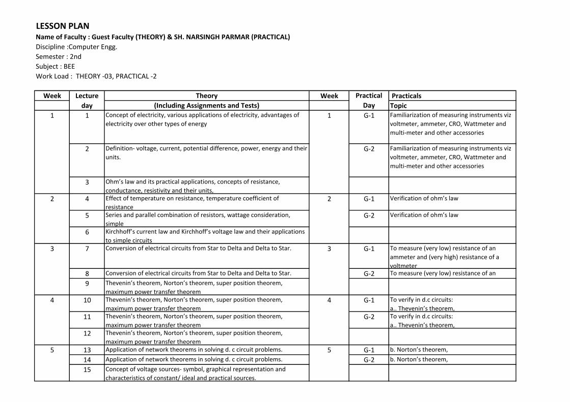
LESSON PLAN
Name of Faculty : Guest Faculty (THEORY) & SH. NARSINGH PARMAR (PRACTICAL)
Discipline :Computer Engg.
Semester : 2nd
Subject : BEE
Work Load : THEORY -03, PRACTICAL -2
Week Theory Week Practicals
(Including Assignments and Tests) Topic
1 Concept of electricity, various applications of electricity, advantages of
electricity over other types of energy
G-1 Familiarization of measuring instruments viz
voltmeter, ammeter, CRO, Wattmeter and
multi-meter and other accessories
2 Definition- voltage, current, potential difference, power, energy and their
units.
G-2 Familiarization of measuring instruments viz
voltmeter, ammeter, CRO, Wattmeter and
multi-meter and other accessories
3 Oh ’s la a d its pra ti al appli atio s, o epts of resista e, conductance, resistivity and their units,
4 Effect of temperature on resistance, temperature coefficient of
resistance
G-1 Verifi atio of oh ’s la
5 Series and parallel combination of resistors, wattage consideration,
simple
G-2 Verifi atio of oh ’s la
6 Kir hhoff’s urre t la a d Kir hhoff’s oltage la a d their appli atio s to simple circuits
7 Conversion of electrical circuits from Star to Delta and Delta to Star. G-1 To measure (very low) resistance of an
ammeter and (very high) resistance of a
voltmeter
8 Conversion of electrical circuits from Star to Delta and Delta to Star. G-2 To measure (very low) resistance of an
ammeter and (very high) resistance of a 9 The e i ’s theore , Norto ’s theore , super positio theore , maximum power transfer theorem
10 The e i ’s theore , Norto ’s theore , super positio theore , maximum power transfer theorem
G-1 To verify in d.c circuits:
a.. The e i ’s theore ,11 The e i ’s theore , Norto ’s theore , super positio theore ,
maximum power transfer theorem
G-2 To verify in d.c circuits:
a.. The e i ’s theore ,12 The e i ’s theore , Norto ’s theore , super positio theore ,
maximum power transfer theorem
13 Application of network theorems in solving d. c circuit problems. G-1 . Norto ’s theore ,14 Application of network theorems in solving d. c circuit problems. G-2 . Norto ’s theore ,15 Concept of voltage sources- symbol, graphical representation and
characteristics of constant/ ideal and practical sources.
4
5
4
5
Practical
Day
11
2
3
2
3
Lecture
day
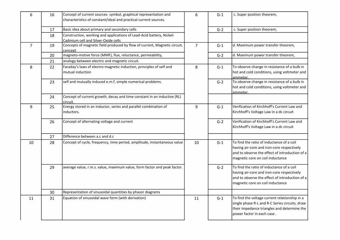
16 Concept of current sources- symbol, graphical representation and
characteristics of constant/ideal and practical current sources.
G-1 c. Super position theorem,
17 Basic idea about primary and secondary cells G-2 c. Super position theorem,
18 Construction, working and applications of Lead-Acid battery, Nickel-
Cadmium cell and Silver-Oxide cells
19 Concepts of magnetic field produced by flow of current, Magnetic circuit,
concept
G-1 d. Maximum power transfer theorem,
20 magneto-motive force (MMF), flux, reluctance, permeability, G-2 d. Maximum power transfer theorem,
21 analogy between electric and magnetic circuit.
22 Faraday’s la s of ele tro- ag eti i du tio , pri iples of self a d mutual induction
G-1 To observe change in resistance of a bulb in
hot and cold conditions, using voltmeter and
ammeter.
23 self and mutually induced e.m.f, simple numerical problems. G-2 To observe change in resistance of a bulb in
hot and cold conditions, using voltmeter and
ammeter.
24 Concept of current growth, decay and time constant in an inductive (RL)
circuit.
25 Energy stored in an inductor, series and parallel combination of
inductors.
G-1 Verification of Kirchhoff's Current Law and
Kirchhoff's Voltage Law in a dc circuit
26 Concept of alternating voltage and current G-2 Verification of Kirchhoff's Current Law and
Kirchhoff's Voltage Law in a dc circuit
27 Difference between a.c and d.c
28 Concept of cycle, frequency, time period, amplitude, instantaneous value G-1 To find the ratio of inductance of a coil
having air-core and iron-core respectively
and to observe the effect of introduction of a
magnetic core on coil inductance
29 average value, r.m.s. value, maximum value, form factor and peak factor. G-2 To find the ratio of inductance of a coil
having air-core and iron-core respectively
and to observe the effect of introduction of a
magnetic core on coil inductance
30 Representation of sinusoidal quantities by phasor diagrams
31 Equation of sinusoidal wave form (with derivation) G-1 To find the voltage current relationship in a
single phase R-L and R-C Series circuits, draw
their impedance triangles and determine the
power factor in each case .
6
7
8
9
10
11
9
10
11
6
7
8
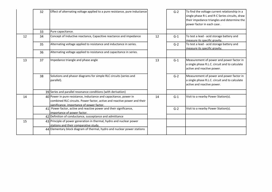
32 Effect of alternating voltage applied to a pure resistance, pure inductance G-2 To find the voltage current relationship in a
single phase R-L and R-C Series circuits, draw
their impedance triangles and determine the
power factor in each case .
33 Pure capacitance.
34 Concept of Inductive reactance, Capacitive reactance and impedance G-1 To test a lead - acid storage battery and
measure its specific gravity.
35 Alternating voltage applied to resistance and inductance in series. G-2 To test a lead - acid storage battery and
measure its specific gravity.
36 Alternating voltage applied to resistance and capacitance in series.
37 Impedance triangle and phase angle G-1 Measurement of power and power factor in
a single phase R.L.C. circuit and to calculate
active and reactive power.
38 Solutions and phasor diagrams for simple RLC circuits (series and
parallel).
G-2 Measurement of power and power factor in
a single phase R.L.C. circuit and to calculate
active and reactive power.
39 Series and parallel resonance conditions (with derivation)
40 Power in pure resistance, inductance and capacitance, power in
combined RLC circuits. Power factor, active and reactive power and their
significance, importance of power factor.
G-1 Visit to a nearby Power Station(s).
41 Power factor, active and reactive power and their significance,
importance of power factor.
G-2 Visit to a nearby Power Station(s).
42 Definition of conductance, susceptance and admittance
43 Principle of power generation in thermal, hydro and nuclear power
stations and their comparative study.
44 Elementary block diagram of thermal, hydro and nuclear power stations
1414
15
12
13
12
13

Week Practicals
Topic
1 Principle and utility of detail and assembly drawings
2 Wooden joints i.e. corner mortice and tenon joint, Tee halving joint, Mitre faced
corner joint, Tee bridle joint, Crossed wooden joint, Cogged joint, Dovetail joint,
Through Mortice and Tenon joint, furniture drawing - freehand and with the help
of drawing instruments.
3 Screw threads and threaded fasteners (8 sheets) Types of threads-External and
Internal threads,
4 Right and Left hand threads (Actual and Conventional representation),
5 single and multiple start threads.
6 Different Forms of screw threads-V threads B.S.W threads
7 B.A thread (American National ) Metric thread
8 Square threads (square Acme,) Buttress and Knuckle thread
9 Different views of hexagonal and square nuts and hexagonal headed bolt
10 Assembly of Hexagonal headed bolt and Hexagonal nut with washer.
11 Assembly of square headed bolt with hexagonal and with washer.
12 Different types of locking devices-Lock nut, castle nut, split pin nut, locking plate,
slotted nut and spring washe
13 Foundations bolts-Rag bolt, Lewis bolt, curved bolt and eye bolt.
14 Drawing of various types of machine screw, set screw, studs and washers
15
Various types of keys and cotters and their practical application and preparation of
drawing of various keys and cotters showing keys and cotters in position
16 Various types of joints (3 sheets) Spigot and socket joint
17 Gib and cotter joint
18 Knuckle joint
19 Types of general purpose-rivets heads (4 Sheets)
20 Caulking and fullering of riveted joints
21 Types of riveted joints
(i) Lap joint-Single riveted, double riveted (chain and zig-zag type)
(ii) Single riveted, Single cover plate butt joint (chain type)
22 (iii) Single riveted, double cover plate butt joint (chain type)
(iv) Double riveted, double cover plate butt joint(chain and zig-zag type)
23 Couplings (2 sheets) Flange coupling (Protected and non-protected),
24 Couplings (2 sheets) Flange coupling (Protected and non-protected),
25 muff coupling and half-lap muff coupling
26 muff coupling and half-lap muff coupling
27 Civil engineering sanitary fitting symbols
28 Electrical fitting symbols for domestic interior installations
29Concept of AutoCAD, Tool bars in AutoCAD, coordinate system, snap, grid, and
ortho mode
30Drawi g co a ds – poi t, li e, arc, circle, ellipse Editi g co a ds – scale, erase, copy, stretch, lengthen and explode
14
15
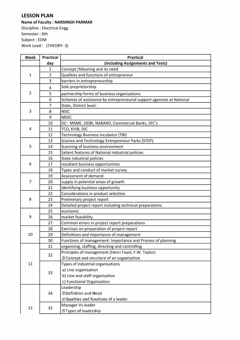
LESSON PLAN
Name of Faculty : Guest Faculty (Practical)
Discipline : Electrical Engg.
Semester : 2nd
Subject : ED-II
Work Load : Practical-6
2
3
4
5
6
Practical
Day
1
13
12
7
8
9
10
11

Week Practical
(Including Assignments and Tests)
1 Concept /Meaning and its need
2 Qualities and functions of entrepreneur
3 barriers in entrepreneurship
4 Sole proprietorship
5 partnership forms of business organisations
6 Schemes of assistance by entrepreneurial support agencies at National
7 State, District level:
8 NSIC
9 NRDC
10 DC: MSME, SIDBI, NABARD, Co ercial Ba ks, SFC’s11 TCO, KVIB, DIC
12 Technology Business Incubator (TBI)
13 Science and Technology Entrepreneur Parks (STEP).
14 Scanning of business environment
15 Salient features of National industrial policies
16 State industrial policies
17 resultant business opportunities
18 Types and conduct of market survey
19 Assessment of demand
20 supply in potential areas of growth
21 Identifying business opportunity
22 Considerations in product selection
23 Preliminary project report
24 Detailed project report including technical preparations
25 economic
26 market feasibility
27 Common errors in project report preparations
28 Exercises on preparation of project report
29 Definitions and importance of management
30 Functions of management: Importance and Process of planning
31 organising, staffing, directing and controlling
32Principles of management (Henri Fayol, F.W. Taylor)
33
Types of industrial organisations
a) Line organisation
b) Line and staff organisation
c) Functional Organisation
34
Leadership
35Manager Vs leader
Practical
day
1
2
LESSON PLAN
Name of Faculty : NARSINGH PARMAR
Discipline : Electrical Engg.
Semester : 6th
Subject : EDM
Work Load : (THEORY- 3)
3
9
12
4
5
6
7
8
10
11

36
Motivation
37 Theories of motivation (Maslow, Herzberg, McGregor)
38
Management Scope in Different Areas (06 hrs)
a) Human Resource Management
39
40
Material and Store Management
41
Marketing and sales
42
43
Financial Management
VAT
44
Miscellaneous Topics
a) Customer Relation Management (CRM)
45
b) Total Quality Management (TQM)
46
Intellectual Property Right (IPR)
15
13
14


LESSON PLAN
Name of Faculty : Ved Parkash
Discipline : Electrical Engg.
Semester : 4th
Subject : EEDD (Practical)
Work Load : Practicals-6
Week Practicals
Topic
G-1 DOL starting of 3-phase induction motor
G-2 DOL starting of 3-phase induction motor
G-1 3-phase induction motor getting supply from selected feeder
G-2 3-phase induction motor getting supply from selected feeder
G-1 Forwarding/reversing of a 3-phase induction motor
G-2 Forwarding/reversing of a 3-phase induction motor
G-1 Two speed control of 3-phase induction motor
G-2 Two speed control of 3-phase induction motor
G-1 Limit switch control of a 3-phase induction motor
G-2 Limit switch control of a 3-phase induction motor
G-1 Sequential operating of two motors using time delay relay
G-2 Sequential operating of two motors using time delay relay
G-1 Manually generated star delta starter for 3-phase induction motor
G-2 Manually generated star delta starter for 3-phase induction motor
G-1 Automatic star delta starter for 3-phase Induction Motor
G-2 Automatic star delta starter for 3-phase Induction Motor
G-1 Concept and purpose of earthing &Procedure of earthing, test of
materials required and costing, Method of reducing earth resistance
G-2 Concept and purpose of earthing &Procedure of earthing, test of
materials required and costing, Method of reducing earth resistance
G-1 Different types of earthing, drawings of plate earthing
G-2 Different types of earthing, drawings of plate earthing
G-1 pipe earthing
G-2 pipe earthing
G-1 Relevant IS specifications of earth electrode for earthing a
transformer, a high building & Earthing layout of distribution
transformer
G-2 Relevant IS specifications of earth electrode for earthing a
transformer, a high building & Earthing layout of distribution
transformer
G-1 Substation earthing layout and earthing materials
G-2 Substation earthing layout and earthing materials
G-1 Key diagram of 11KV, 33Kv
G-2 Key diagram of 11KV, 33Kv
G-1 Key diagram of 66KV
G-2 Key diagram of 66KV
5
6
7
8
Practical Day
1
2
3
4

G-1 Key diagram of 132 KV sub-stations
G-2 Key diagram of 132 KV sub-stations
G-1 End cover of induction motor
G-2 End cover of induction motor
G-1 Rotor of a squirrel cage induction motor
G-2 Rotor of a squirrel cage induction motor
G-1 Field coil of a DC motor & Terminal plate of an induction motor
G-2 Field coil of a DC motor & Terminal plate of an induction motor
G-1 Terminal plate of induction motor
G-2 Terminal plate of induction motor
G-1 Motor body (induction motor) as per IS specifications &
G-2 Motor body (induction motor) as per IS specifications &
G-1 Sliprings of 3-phase induction motor
G-2 Sliprings of 3-phase induction motor
G-1 RIVISION
G-2 RIVISION
G-1 RIVISION
G-2 RIVISION
G-1 RIVISION
G-2 RIVISION
G-1 RIVISION
G-2 RIVISION
G-1 RIVISION
G-2 RIVISION
G-1 RIVISION
G-2 RIVISION
G-1 RIVISION
G-2 RIVISION
G-1 RIVISION
G-2 RIVISION
15
10
11
12
13
14
8
9
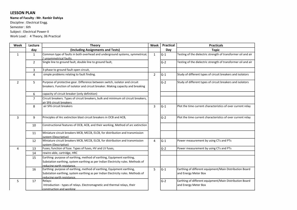
LESSON PLANName of Faculty : Mr. Ranbir Dahiya
Discipline : Electrical Engg.
Semester : 6th
Subject : Electrical Power-II
Work Load : 4 Theory, 06 Practical
Week Theory Week Practicals
(Including Assignments and Tests) Topic
1 Common type of faults in both overhead and underground systems, symmetricaL
/ unsymmetrical faults.
G-1 Testing of the dielectric strength of transformer oil and air
2 Single line to ground fault, double line to ground fault, G-2 Testing of the dielectric strength of transformer oil and air
3 3-phase to ground fault open circuit,
4 simple problems relating to fault finding. G-1 Study of different types of circuit breakers and isolators
5 Purpose of protective gear. Difference between switch, isolator and circuit
breakers. Function of isolator and circuit breaker. Making capacity and breaking
G-2 Study of different types of circuit breakers and isolators
6 capacity of circuit breaker (only definition)
7 Circuit breakers. Types of circuit breakers, bulk and minimum oil circuit breakers,
air SF6 circuit breakers
8 air SF6 circuit breakers G-1 Plot the time current characteristics of over current relay
9 Principles of Arc extinction blast circuit breakers in OCB and ACB, G-2 Plot the time current characteristics of over current relay
10 Constructional features of OCB, ACB, and their working, Method of arc extinction
11 Miniature circuit breakers MCB, MCCB, ELCB, for distribution and transmission
system (Descriptive)
12 Miniature circuit breakers MCB, MCCB, ELCB, for distribution and transmission
system (Descriptive)
G-1 Power measurement by using CTs and PTs
13 Fuses; function of fuse. Types of fuses, HV and LV fuses, G-2 Power measurement by using CTs and PTs
14 rewire-able, cartridge, HRC
15 Earthing: purpose of earthing, method of earthing, Equipment earthing,
Substation earthing, system earthing as per Indian Electricity rules. Methods of
reducing earth resistance.
16 Earthing: purpose of earthing, method of earthing, Equipment earthing,
Substation earthing, system earthing as per Indian Electricity rules. Methods of
reducing earth resistance.
G-1 Earthing of different equipment/Main Distribution Board
and Energy Meter Box
17 Relays:
Introduction - types of relays. Electromagnetic and thermal relays, their
construction and working
G-2 Earthing of different equipment/Main Distribution Board
and Energy Meter Box
1
Lecture
day
Practical
Day
1
2
5
2
3
4
5
3
4
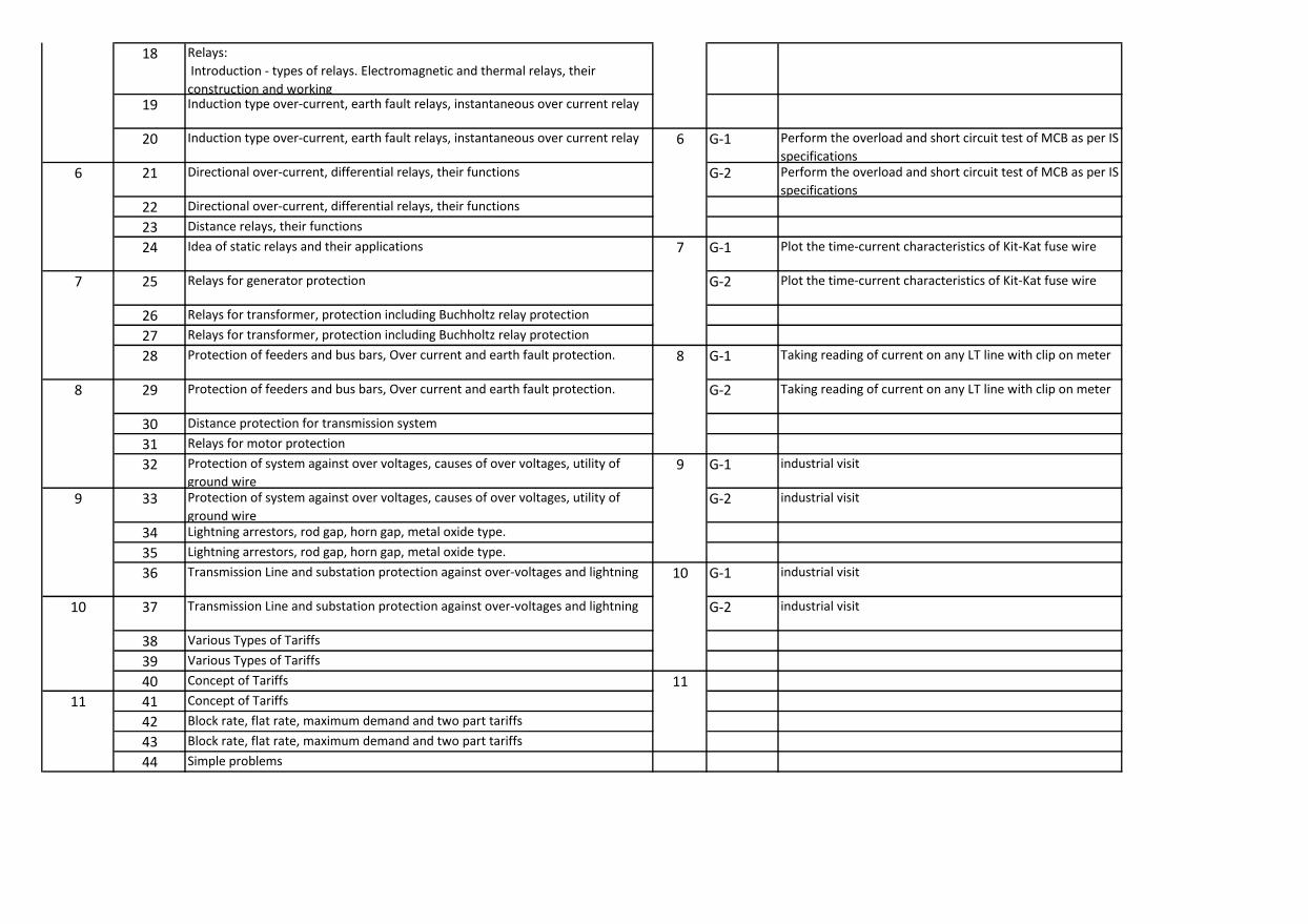
18 Relays:
Introduction - types of relays. Electromagnetic and thermal relays, their
construction and working
19 Induction type over-current, earth fault relays, instantaneous over current relay
20 Induction type over-current, earth fault relays, instantaneous over current relay G-1 Perform the overload and short circuit test of MCB as per IS
specifications
21 Directional over-current, differential relays, their functions G-2 Perform the overload and short circuit test of MCB as per IS
specifications
22 Directional over-current, differential relays, their functions
23 Distance relays, their functions
24 Idea of static relays and their applications G-1 Plot the time-current characteristics of Kit-Kat fuse wire
25 Relays for generator protection G-2 Plot the time-current characteristics of Kit-Kat fuse wire
26 Relays for transformer, protection including Buchholtz relay protection
27 Relays for transformer, protection including Buchholtz relay protection
28 Protection of feeders and bus bars, Over current and earth fault protection. G-1 Taking reading of current on any LT line with clip on meter
29 Protection of feeders and bus bars, Over current and earth fault protection. G-2 Taking reading of current on any LT line with clip on meter
30 Distance protection for transmission system
31 Relays for motor protection
32 Protection of system against over voltages, causes of over voltages, utility of
ground wire
G-1 industrial visit
33 Protection of system against over voltages, causes of over voltages, utility of
ground wire
G-2 industrial visit
34 Lightning arrestors, rod gap, horn gap, metal oxide type.
35 Lightning arrestors, rod gap, horn gap, metal oxide type.
36 Transmission Line and substation protection against over-voltages and lightning G-1 industrial visit
37 Transmission Line and substation protection against over-voltages and lightning G-2 industrial visit
38 Various Types of Tariffs
39 Various Types of Tariffs
40 Concept of Tariffs
41 Concept of Tariffs
42 Block rate, flat rate, maximum demand and two part tariffs
43 Block rate, flat rate, maximum demand and two part tariffs
44 Simple problems
8
9
6
10
11
6
7
8
9
10
11
7

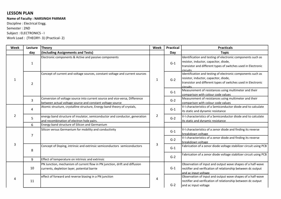
Week Theory Week Practicals
(Including Assignments and Tests) Topic
1
Electronic components & Active and passive components
G-1
Identification and testing of electronic components such as
resistor, inductor, capacitor, diode,
transistor and different types of switches used in Electronic
circuits
G-2
Identification and testing of electronic components such as
resistor, inductor, capacitor, diode,
transistor and different types of switches used in Electronic
circuits
G-1Measurement of resistances using multimeter and their
comparison with colour code values
3Conversion of voltage source into current source and vice-versa, Difference
between actual voltage source and constant voltage sourceG-2
Measurement of resistances using multimeter and their
comparison with colour code values
4Atomic structure, crystalline structure, Energy band theory of crystals,
G-1V-I characteristics of a Semiconductor diode and to calculate
its static and dynamic resistance
5energy band structure of insulator, semiconductor and conductor, generation
and recombination of electron hole pairs.G-2
V-I characteristics of a Semiconductor diode and to calculate
its static and dynamic resistance
6 Energy band structure of Silicon and Germanium
G-1V-I characteristics of a zenor diode and finding its reverse
breakdown voltage
G-2V-I characteristics of a zenor diode and finding its reverse
breakdown voltage
G-1Fabrication of a zenor diode voltage stabilizer circuit using PCB
9 Effect of temperature on intrinsic and extrinsic
10PN Junction, mechanism of current flow in PN junction, drift and diffusion
currents, depletion layer, potential barrie G-1Observation of input and output wave shapes of a half-wave
rectifier and verification of relationship between dc output
and ac input voltage
11
effect of forward and reverse biasing in a PN junction
Fabrication of a zenor diode voltage stabilizer circuit using PCB
Observation of input and output wave shapes of a half-wave
rectifier and verification of relationship between dc output
and ac input voltageG-2
Practical
Day
LESSON PLAN
Name of Faculty : NARSINGH PARMAR
Discipline : Electrical Engg.
Semester : 2ND
Subject : ELECTRONICS - I
Work Load : (THEORY- 3) (Practical- 2)
Lecture
day
1
2
3
4 4
Concept of current and voltage sources, constant voltage and current sources
2
7
8
G-2
1
2
3
Silicon versus Germanium for mobility and conductivity
Concept of Doping, intrinsic and extrinsic semiconductors semiconductors
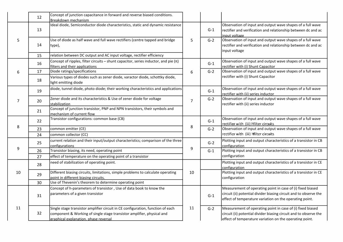
12Concept of junction capacitance in forward and reverse biased conditions.
Breakdown mechanism
13Ideal diode, Semiconductor diode characteristics, static and dynamic resistance
G-1Observation of input and output wave shapes of a full wave
rectifier and verification and relationship between dc and ac
input voltage
14
Use of diode as half wave and full wave rectifiers (centre tapped and bridge
type),
15 relation between DC output and AC input voltage, rectifier efficiency
16Co cept of ripples, filter circuits – shu t capacitor, series i ductor, a d pie π filters and their applications
G-1Observation of input and output wave shapes of a full wave
rectifier with (i) Shunt Capacitor
17 Diode ratings/specifications
18Various types of diodes such as zener diode, varactor diode, schottky diode,
light emitting diode
19diode, tunnel diode, photo diode; their working characteristics and applications
G-1Observation of input and output wave shapes of a full wave
rectifier with (ii) series inductor
20Zener diode and its characteristics & Use of zener diode for voltage
stabilization
21Concept of junction transistor, PNP and NPN transistors, their symbols and
mechanism of current flow
22Transistor configurations: common base (CB)
G-1Observation of input and output wave shapes of a full wave
23 common emitter (CE)
24 common collector (CC)
25current relation and their input/output characteristics; comparison of the three
configurationsG-2
Plotting input and output characteristics of a transistor in CB
configuration
26 Transistor biasing, its need, operating point
27 effect of temperature on the operating point of a transistor
28need of stabilization of operating point. Plotting input and output characteristics of a transistor in CE
configuration
29Different biasing circuits, limitations, simple problems to calculate operating
point in different biasing circuits.
30 Use of Theve i ’s theore to deter i e operati g poi t
31
Concept of h-parameters of transistor , Use of data book to know the
parameters of a given transistorG-1
Measurement of operating point in case of (i) fixed biased
circuit (ii) potential divider biasing circuit and to observe the
effect of temperature variation on the operating point.
32Single stage transistor amplifier circuit in CE configuration, function of each
component & Working of single stage transistor amplifier, physical and
graphical explanation, phase reversal
7
8
9
10
11
Observation of input and output wave shapes of a full wave
rectifier and verification and relationship between dc and ac
input voltage
Observation of input and output wave shapes of a full wave
rectifier with (i) Shunt Capacitor
Observation of input and output wave shapes of a full wave
rectifier with (ii) series inductor
Plotting input and output characteristics of a transistor in CB
configuration
7
5
6
5
6
11
G-2 Observation of input and output wave shapes of a full wave 8
9
10 Plotting input and output characteristics of a transistor in CE
configuration
G-2 Measurement of operating point in case of (i) fixed biased
circuit (ii) potential divider biasing circuit and to observe the
effect of temperature variation on the operating point.
G-1
G-2
G-2
G-2

33Concept of DC and AC load line & Voltage gain of single stage transistor
amplifier using characteristics of the device
34Concept of input and output impedance & AC equivalent circuit of single stage
transistor amplifiers G-1To measure the voltage gain and band width by plotting
frequency response curve of a single stage amplifier using CE
configuration at different loads
35Calculation of voltage gain using AC equivalent circuit & Frequency response of
a single stage transistor amplifier
36Need of ulti-stage tra sistor a plifiers – differe t types of coupli gs, their purpose and applications.
37
Knowledge of various terms such as voltage gain, current gain, power gain,
frequency response, decibel gain and band widthG-1
To study the effect of coupling capacitor on lower cut off
frequency and upper cut off frequency by plotting frequency
response curve of a two stage RC coupled amplifier
38RC coupled two-stage amplifiers, circuit details, working, frequency response,
applications & Loading effect in multistage amplifiers
39Elementary idea about direct coupled amplifier, its limitations and applications
40 Transformer coupled amplifiers, its frequency response G-1 To plot V-I characteristics of a FET
41Effect of co-efficient of coupling on frequency response. Applications of
transformer coupled amplifiers
42Construction, operation, characteristics and applications of a N channel JFET
and P channel JFET
43 JFET as an amplifier G-1 Assessment
44Types, construction, operation, characteristics and applications of a MOSFET
45 Comparison between BJT, JFET and MOSFET
15
12
13
14
15
12
13
14
effect of temperature variation on the operating point.
G-2 To measure the voltage gain and band width by plotting
frequency response curve of a single stage amplifier using CE
configuration at different loads
To study the effect of coupling capacitor on lower cut off
frequency and upper cut off frequency by plotting frequency
response curve of a two stage RC coupled amplifier
G-2 To plot V-I characteristics of a FET
G-2 Assessment
G-2


LESSON PLAN
Name of Faculty : Guest Faculty (THEORY) & SH. NARSINGH PARMAR (PRACTICAL)
Discipline : Electrical Engg.
Semester : 4th
Subject : Electronics -II
Work Load : THEORY-04 , PRACTICAL -03
Week Lecture
Day
Theory Practicals
Topic Topic
1 Difference between voltage and power amplifier
G-1
To study the effect of coupling capacitor on lower cut off
frequency and upper cut off frequency by plotting frequency
response curve of a two stage RC coupled amplifier
2 Important terms in Power Amplifier
3 collector efficiency, distortion and dissipation capability
4 Classification of power amplifier class A
5 B and CG-1
To measure (a) optimum load (b) output power (c) signal handling
capacity of a push-pull amplifier
6 Class A single-ended power amplifier,
7 its working and collector efficiency
8 Impedance matching in a power amplifier using transformer
9 Heat sinks in power amplifiers
G-1
To observe the effect of negative current feedback on the voltage
gain of a single stage transistor amplifier by removing emitter bye-
pass capacitor.
10 Push-pull amplifier: circuit details,
11 working and advantages (no mathematical derivations)
12 Tuned Voltage Amplifier- Introduction
13 Series G-1 To measure (a) voltage gain
14 parallel resonance ( No mathematical derivation)
15 Single and double tuned voltage amplifiers
16 Frequency response of tuned voltage amplifiers
Week
1
2
3
4
1
2
3
4
Practical
Day
G-2
To study the effect of coupling capacitor on lower cut off
frequency and upper cut off frequency by plotting frequency
response curve of a two stage RC coupled amplifier
G-2
To measure (a) optimum load (b) output power (c) signal handling
capacity of a push-pull amplifier
G-2
To observe the effect of negative current feedback on the voltage
gain of a single stage transistor amplifier by removing emitter bye-
pass capacitor.
G-2
To measure (a) voltage gain
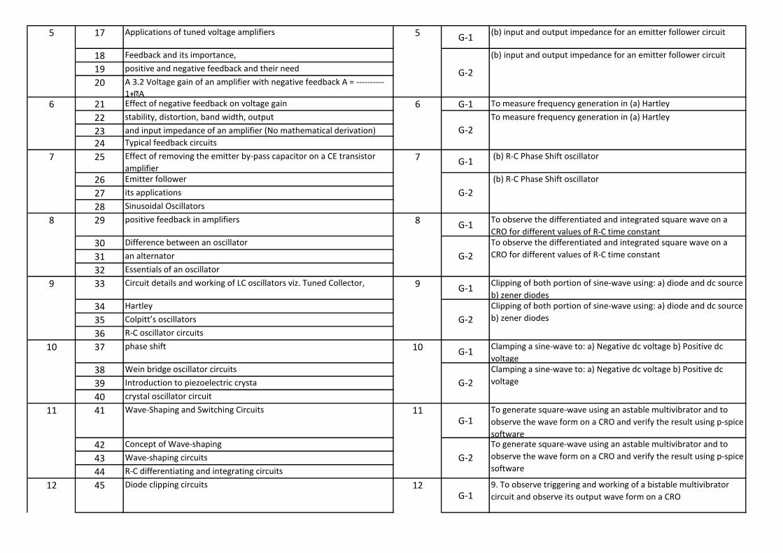
17 Applications of tuned voltage amplifiersG-1
(b) input and output impedance for an emitter follower circuit
18 Feedback and its importance,
19 positive and negative feedback and their need
20 A 3.2 Voltage gain of an amplifier with negative feedback A = ----------
21 Effect of negative feedback on voltage gain G-1 To measure frequency generation in (a) Hartley
22 stability, distortion, band width, output
23 and input impedance of an amplifier (No mathematical derivation)
24 Typical feedback circuits
25 Effect of removing the emitter by-pass capacitor on a CE transistor
amplifierG-1
(b) R-C Phase Shift oscillator
26 Emitter follower
27 its applications
28 Sinusoidal Oscillators
29 positive feedback in amplifiersG-1
To observe the differentiated and integrated square wave on a
CRO for different values of R-C time constant
30 Difference between an oscillator
31 an alternator
32 Essentials of an oscillator
33 Circuit details and working of LC oscillators viz. Tuned Collector, G-1
Clipping of both portion of sine-wave using: a) diode and dc source
b) zener diodes
34 Hartley
35 Colpitt’s oscillators36 R-C oscillator circuits
37 phase shiftG-1
Clamping a sine-wave to: a) Negative dc voltage b) Positive dc
voltage
38 Wein bridge oscillator circuits
39 Introduction to piezoelectric crysta
40 crystal oscillator circuit
41 Wave-Shaping and Switching Circuits
G-1
To generate square-wave using an astable multivibrator and to
observe the wave form on a CRO and verify the result using p-spice
software
42 Concept of Wave-shaping
43 Wave-shaping circuits
44 R-C differentiating and integrating circuits
45 Diode clipping circuits
G-1
9. To observe triggering and working of a bistable multivibrator
circuit and observe its output wave form on a CRO
11
12
6
7
8
9
10
5 5
6
7
8
9
10
11
12
(b) input and output impedance for an emitter follower circuit
G-2
G-2
To measure frequency generation in (a) Hartley
G-2
(b) R-C Phase Shift oscillator
G-2
To observe the differentiated and integrated square wave on a
CRO for different values of R-C time constant
G-2
Clipping of both portion of sine-wave using: a) diode and dc source
b) zener diodes
G-2
Clamping a sine-wave to: a) Negative dc voltage b) Positive dc
voltage
G-2
To generate square-wave using an astable multivibrator and to
observe the wave form on a CRO and verify the result using p-spice
software
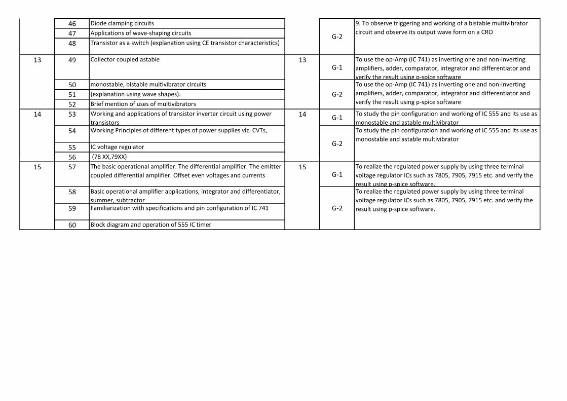
46 Diode clamping circuits
47 Applications of wave-shaping circuits
48 Transistor as a switch (explanation using CE transistor characteristics)
49 Collector coupled astable
G-1
To use the op-Amp (IC 741) as inverting one and non-inverting
amplifiers, adder, comparator, integrator and differentiator and
verify the result using p-spice software
50 monostable, bistable multivibrator circuits
51 (explanation using wave shapes).
52 Brief mention of uses of multivibrators
53 Working and applications of transistor inverter circuit using power
transistorsG-1
To study the pin configuration and working of IC 555 and its use as
monostable and astable multivibrator
54 Working Principles of different types of power supplies viz. CVTs,
55 IC voltage regulator
56 (78 XX,79XX)
57 The basic operational amplifier. The differential amplifier. The emitter
coupled differential amplifier. Offset even voltages and currents G-1
To realize the regulated power supply by using three terminal
voltage regulator ICs such as 7805, 7905, 7915 etc. and verify the
result using p-spice software.
58 Basic operational amplifier applications, integrator and differentiator,
summer, subtractor
59 Familiarization with specifications and pin configuration of IC 741
60 Block diagram and operation of 555 IC timer
13
14
1515
13
14
G-2
To realize the regulated power supply by using three terminal
voltage regulator ICs such as 7805, 7905, 7915 etc. and verify the
result using p-spice software.
G-2
9. To observe triggering and working of a bistable multivibrator
circuit and observe its output wave form on a CRO
G-2
To use the op-Amp (IC 741) as inverting one and non-inverting
amplifiers, adder, comparator, integrator and differentiator and
verify the result using p-spice software
G-2
To study the pin configuration and working of IC 555 and its use as
monostable and astable multivibrator
Week Theory Week Practicals
(Including Assignments and Tests) Topic
1
Electronic components & Active and passive components
G-1
Identification and testing of electronic components such as
resistor, inductor, capacitor, diode,
transistor and different types of switches used in Electronic
circuits
G-2
Identification and testing of electronic components such as
resistor, inductor, capacitor, diode,
transistor and different types of switches used in Electronic
circuits
G-1Measurement of resistances using multimeter and their
comparison with colour code values
3Conversion of voltage source into current source and vice-versa, Difference
between actual voltage source and constant voltage sourceG-2
Measurement of resistances using multimeter and their
comparison with colour code values
4Atomic structure, crystalline structure, Energy band theory of crystals,
G-1V-I characteristics of a Semiconductor diode and to calculate
its static and dynamic resistance
5energy band structure of insulator, semiconductor and conductor, generation
and recombination of electron hole pairs.G-2
V-I characteristics of a Semiconductor diode and to calculate
its static and dynamic resistance
6 Energy band structure of Silicon and Germanium
G-1V-I characteristics of a zenor diode and finding its reverse
breakdown voltage
G-2V-I characteristics of a zenor diode and finding its reverse
breakdown voltage
G-1Fabrication of a zenor diode voltage stabilizer circuit using PCB
9 Effect of temperature on intrinsic and extrinsic
10PN Junction, mechanism of current flow in PN junction, drift and diffusion
currents, depletion layer, potential barrie G-1Observation of input and output wave shapes of a half-wave
rectifier and verification of relationship between dc output
and ac input voltage
11
effect of forward and reverse biasing in a PN junction
2
7
8
G-2
1
2
3
Silicon versus Germanium for mobility and conductivity
Concept of Doping, intrinsic and extrinsic semiconductors semiconductors
Concept of current and voltage sources, constant voltage and current sources
4
1
2
3
4
Practical
Day
LESSON PLAN
Name of Faculty : NARSINGH PARMAR
Discipline : Electrical Engg.
Semester : 2ND
Subject : ELECTRONICS - I
Work Load : (THEORY- 3) (Practical- 2)
Lecture
day
Fabrication of a zenor diode voltage stabilizer circuit using PCB
Observation of input and output wave shapes of a half-wave
rectifier and verification of relationship between dc output
and ac input voltageG-2

12Concept of junction capacitance in forward and reverse biased conditions.
Breakdown mechanism
13Ideal diode, Semiconductor diode characteristics, static and dynamic resistance
G-1Observation of input and output wave shapes of a full wave
rectifier and verification and relationship between dc and ac
input voltage
14
Use of diode as half wave and full wave rectifiers (centre tapped and bridge
type),
15 relation between DC output and AC input voltage, rectifier efficiency
16Co cept of ripples, filter circuits – shu t capacitor, series i ductor, a d pie π filters and their applications
G-1Observation of input and output wave shapes of a full wave
rectifier with (i) Shunt Capacitor
17 Diode ratings/specifications
18Various types of diodes such as zener diode, varactor diode, schottky diode,
light emitting diode
19diode, tunnel diode, photo diode; their working characteristics and applications
G-1Observation of input and output wave shapes of a full wave
rectifier with (ii) series inductor
20Zener diode and its characteristics & Use of zener diode for voltage
stabilization
21Concept of junction transistor, PNP and NPN transistors, their symbols and
mechanism of current flow
22Transistor configurations: common base (CB)
G-1Observation of input and output wave shapes of a full wave
23 common emitter (CE)
24 common collector (CC)
25current relation and their input/output characteristics; comparison of the three
configurationsG-2
Plotting input and output characteristics of a transistor in CB
configuration
26 Transistor biasing, its need, operating point
27 effect of temperature on the operating point of a transistor
28need of stabilization of operating point. Plotting input and output characteristics of a transistor in CE
configuration
29Different biasing circuits, limitations, simple problems to calculate operating
point in different biasing circuits.
30 Use of Theve i ’s theore to deter i e operati g poi t
31
Concept of h-parameters of transistor , Use of data book to know the
parameters of a given transistorG-1
Measurement of operating point in case of (i) fixed biased
circuit (ii) potential divider biasing circuit and to observe the
effect of temperature variation on the operating point.
32Single stage transistor amplifier circuit in CE configuration, function of each
component & Working of single stage transistor amplifier, physical and
graphical explanation, phase reversal
G-1
G-2
G-2
G-2
G-2 Measurement of operating point in case of (i) fixed biased
circuit (ii) potential divider biasing circuit and to observe the
effect of temperature variation on the operating point.
G-2 Observation of input and output wave shapes of a full wave 8
9
10 Plotting input and output characteristics of a transistor in CE
configuration
5
6
11
7
5
6
7
8
9
10
11
Observation of input and output wave shapes of a full wave
rectifier and verification and relationship between dc and ac
input voltage
Observation of input and output wave shapes of a full wave
rectifier with (i) Shunt Capacitor
Observation of input and output wave shapes of a full wave
rectifier with (ii) series inductor
Plotting input and output characteristics of a transistor in CB
configuration
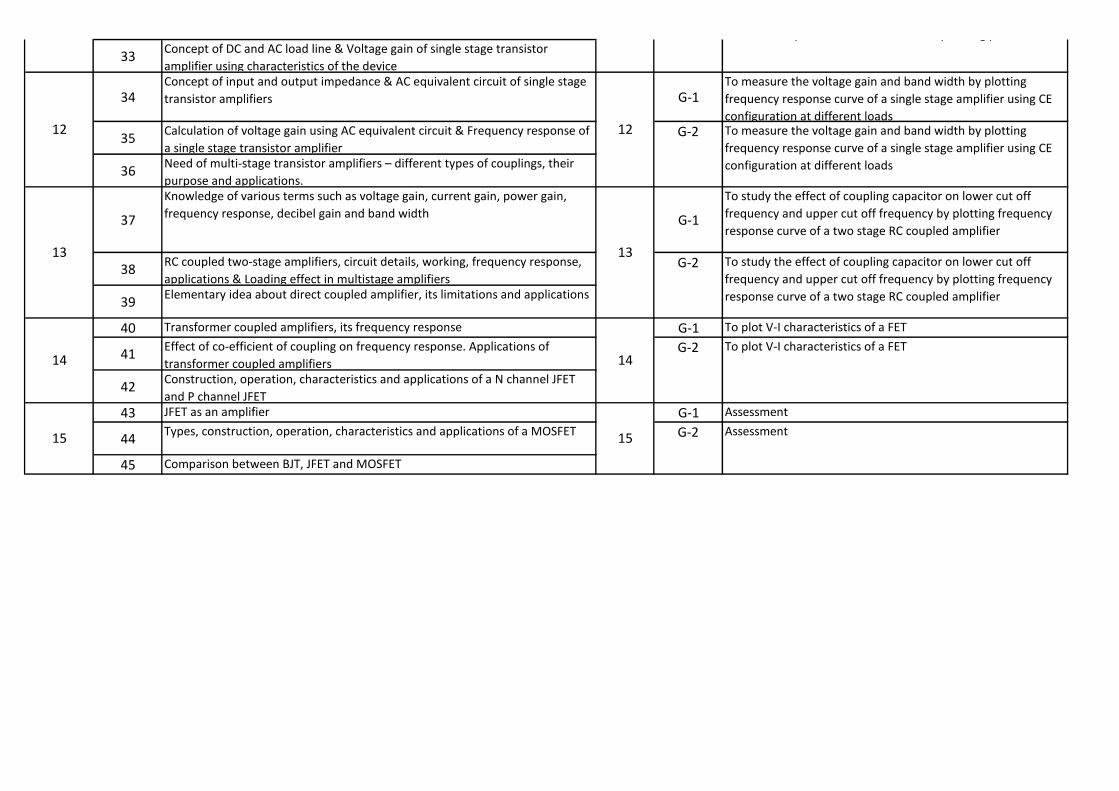
33Concept of DC and AC load line & Voltage gain of single stage transistor
amplifier using characteristics of the device
34Concept of input and output impedance & AC equivalent circuit of single stage
transistor amplifiers G-1To measure the voltage gain and band width by plotting
frequency response curve of a single stage amplifier using CE
configuration at different loads
35Calculation of voltage gain using AC equivalent circuit & Frequency response of
a single stage transistor amplifier
36Need of ulti-stage tra sistor a plifiers – differe t types of coupli gs, their purpose and applications.
37
Knowledge of various terms such as voltage gain, current gain, power gain,
frequency response, decibel gain and band widthG-1
To study the effect of coupling capacitor on lower cut off
frequency and upper cut off frequency by plotting frequency
response curve of a two stage RC coupled amplifier
38RC coupled two-stage amplifiers, circuit details, working, frequency response,
applications & Loading effect in multistage amplifiers
39Elementary idea about direct coupled amplifier, its limitations and applications
40 Transformer coupled amplifiers, its frequency response G-1 To plot V-I characteristics of a FET
41Effect of co-efficient of coupling on frequency response. Applications of
transformer coupled amplifiers
42Construction, operation, characteristics and applications of a N channel JFET
and P channel JFET
43 JFET as an amplifier G-1 Assessment
44Types, construction, operation, characteristics and applications of a MOSFET
45 Comparison between BJT, JFET and MOSFET
G-2
G-2 To plot V-I characteristics of a FET
G-2 Assessment
effect of temperature variation on the operating point.
G-2 To measure the voltage gain and band width by plotting
frequency response curve of a single stage amplifier using CE
configuration at different loads
To study the effect of coupling capacitor on lower cut off
frequency and upper cut off frequency by plotting frequency
response curve of a two stage RC coupled amplifier
15
12
13
14
15
12
13
14


LESSON PLAN
Name of Faculty : Mahinder Kaushik (Theory), Ranbir Singh Dahiya (lab Practical)
Discipline : Electrical Engg.
Semester : 4th
Subject : Electrical Machine-I
Work Load : per week lecture-4, Practical -6
Week Practical Theory Practicals
Topic Topic
1 Introduction to Electrical Machines, Definition of motor and generator,
concept of torque
G-1 Measurement of the angular displacement of the rotor of a slip-ring
induction motor on application of DC to stator of motor winding in
sequence and simultaneously to each phase of rotor winding
2 Torque development due to alignment of two fields and the concept of
torque angle
3 Electro-magnetically induced emf
4 Elementary concept of an electrical machine
5 Comparison of generator and motor G-1 Speed control of dc shunt motor (i) Armature control method
6 Main constructional features, Types of armature winding
7 Main constructional features, Types of armature winding
8 Function of the commutator for motoring and generation action
9 Function of the commutator for motoring and generation action G-1 (ii) Field control method
10 Factors determining induced emf
11 Factors determining the electromagnetic torque
12 Types of dc generation on the basis of excitation, voltage built up in a dc
shunt generator
13 Significance of back e.m.f., the relation between back emf and Terminal
voltage
G-1 Study of dc series motor with starter (to operate the motor on no load
for a moment)
14 Armature Reaction
15 Commutation methods to improve commutation
16 Performance and characteristics of different types of DC motors
17 Performance and characteristics of different types of DC motors G-1 Study of 3 point starter for starting D.C. shunt motor.
18 2.10 Speed control of dc shunt/series motors
19 2.10 Speed control of dc shunt/series motors
Week
1
2
3
1
2
3
4
5
4
5
Practical
Day
G-2
G-2
Measurement of the angular displacement of the rotor of a slip-ring
induction motor on application of DC to stator of motor winding in
sequence and simultaneously to each phase of rotor winding
G-2 Speed control of dc shunt motor (i) Armature control method
G-2 (ii) Field control method
Study of dc series motor with starter (to operate the motor on no load
for a moment)
G-2 Study of 3 point starter for starting D.C. shunt motor.
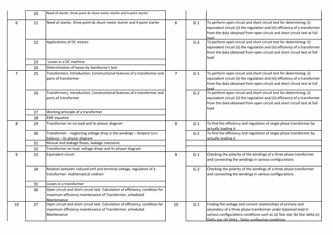
20 Need of starter, three point dc shunt motor starter and 4-point starter
21 Need of starter, three point dc shunt motor starter and 4-point starter G-1 To perform open circuit and short circuit test for determining: (i)
equivalent circuit (ii) the regulation and (iii) efficiency of a transformer
from the data obtained from open circuit and short circuit test at full
load
22 Applications of DC motors
23 Losses in a DC machine
24 Deter i atio of losses y S i ur e’s test25 Transformers, Introduction, Constructional features of a transformer and
parts of transformer
G-1 To perform open circuit and short circuit test for determining: (i)
equivalent circuit (ii) the regulation and (iii) efficiency of a transformer
from the data obtained from open circuit and short circuit test at full
load
26 Transformers, Introduction, Constructional features of a transformer and
parts of transformer
27 Working principle of a transformer
28 EMF equation
29 Transformer on no-load and its phasor diagram G-1 To find the efficiency and regulation of single phase transformer by
actually loading it
30 Tra sfor er – egle ti g oltage drop i the i di gs – A pere tur ala e – its phasor diagra
G-2 To find the efficiency and regulation of single phase transformer by
actually loading it
31 Mutual and leakage fluxes, leakage reactance
32 Transformer on load, voltage drops and its phasor diagram
33 Equivalent circuit G-1 Checking the polarity of the windings of a three phase transformer
and connecting the windings in various configurations
34 Relation between induced emf and terminal voltage, regulation of a
transformer- mathematical relation
35 Losses in a transformer
36 Open circuit and short circuit test. Calculation of efficiency, condition for
maximum efficiency-maintenance of Transformer, scheduled
Maintenance
37 Open circuit and short circuit test. Calculation of efficiency, condition for
maximum efficiency-maintenance of Transformer, scheduled
Maintenance
G-1 Finding the voltage and current relationships of primary and
secondary of a three phase transformer under balanced load in
various configurations conditions such as (a) Star-star (b) Star delta (c)
Delta star (d) Delta - Delta configuring conditions
8
9
10
6
7
8
9
10
6
7
G-2
G-2 To perform open circuit and short circuit test for determining: (i)
equivalent circuit (ii) the regulation and (iii) efficiency of a transformer
from the data obtained from open circuit and short circuit test at full
load
To perform open circuit and short circuit test for determining: (i)
equivalent circuit (ii) the regulation and (iii) efficiency of a transformer
from the data obtained from open circuit and short circuit test at full
load
G-2 Checking the polarity of the windings of a three phase transformer
and connecting the windings in various configurations

38 Auto transformer construction, saving of copper, working and
applications
39 Different types of transformers including dry type transformer.
41 Construction of three phase transformers and accessories of
transformers such as Conservator, breather, Buchholz Relay, Tap Changer
(off load and on load) (Brief idea)
41 Construction of three phase transformers and accessories of
transformers such as Conservator, breather, Buchholz Relay, Tap Changer
(off load and on load) (Brief idea)
G-1 Finding the voltage and current relationships of primary and
secondary of a three phase transformer under balanced load in
various configurations conditions such as (a) Star-star (b) Star delta (c)
Delta star (d) Delta - Delta configuring conditions
42 Types of three phase transformer i.e. delta-delta, delta-star, star-delta
and star-star
43 Conditions for parallel operation (only conditions are to be
studied)power and distribution transformer 4.6 Cooling of transformer
44 On load tap changer
45 Difference between power and distribution transformer
46 Cooling of transformer
47 REVISION
48 REVISION
49 REVISION
50 REVISION
51 REVISION
52 REVISION
53 REVISION
54 REVISION
55 REVISION
56 REVISION
57 REVISION
58 REVISION
59 REVISION
60 REVISION
11
12
13
14
15 15
11
G-2
12
13
14
Finding the voltage and current relationships of primary and
secondary of a three phase transformer under balanced load in
various configurations conditions such as (a) Star-star (b) Star delta (c)
Delta star (d) Delta - Delta configuring conditions
G-2 Finding the voltage and current relationships of primary and
secondary of a three phase transformer under balanced load in
various configurations conditions such as (a) Star-star (b) Star delta (c)
Delta star (d) Delta - Delta configuring conditions

Week Practicals
Topic
1 Mock interview
2 Mock interview
3 Mock interview
4 Preparing for meeting
5 Preparing for meeting
6 Preparing for meeting
7 Preparing for meeting
8 Preparing for meeting
9 Preparing for meeting
10 Preparing for meeting
11 Group discussion
12 Group discussion
13 Group discussion
14 Group discussion
15 Group discussion
16 Seminar presentation
17 Seminar presentation
18 Seminar presentation
19 Seminar presentation
20 Seminar presentation
21 Elements of good presentation
22 Elements of good presentation
23 Elements of good presentation
24 Structure and tools of presentation
25 Structure and tools of presentation
26 Structure and tools of presentation
27 Paper reading
28 Paper reading
29 Paper reading
30 Power point presentation
31 Power point presentation
32 Power point presentation
5
6
Work Load : PRACTICAL-02
LESSON PLAN
Name of Faculty : Mahinder Kaushik (Practical)
Discipline : Electrical Engg.
Semester : 6th
Subject : Emp. Skills-II Practical
Practical
Day
1
2
3
4
13
15
16
14
7
8
9
10
11
12

LESSON PLAN
Name of Faculty : Mrs. Preeti Girdhar
Discipline : Electrical Engg.
Semester : 4th
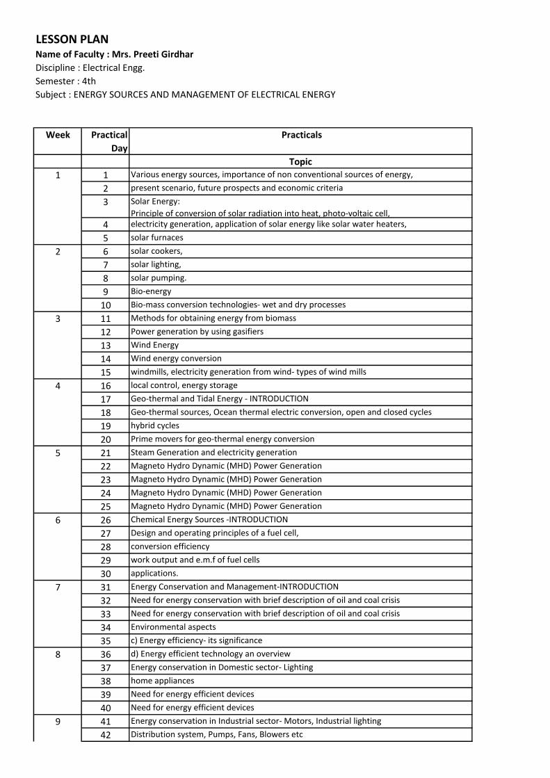
Subject : ENERGY SOURCES AND MANAGEMENT OF ELECTRICAL ENERGY
Week Practical
Day
Practicals
Topic
1 Various energy sources, importance of non conventional sources of energy,
2 present scenario, future prospects and economic criteria
3 Solar Energy:
Principle of conversion of solar radiation into heat, photo-voltaic cell,
4 electricity generation, application of solar energy like solar water heaters,
5 solar furnaces
6 solar cookers,
7 solar lighting,
8 solar pumping.
9 Bio-energy
10 Bio-mass conversion technologies- wet and dry processes
11 Methods for obtaining energy from biomass
12 Power generation by using gasifiers
13 Wind Energy
14 Wind energy conversion
15 windmills, electricity generation from wind- types of wind mills
16 local control, energy storage
17 Geo-thermal and Tidal Energy - INTRODUCTION
18 Geo-thermal sources, Ocean thermal electric conversion, open and closed cycles
19 hybrid cycles
20 Prime movers for geo-thermal energy conversion
21 Steam Generation and electricity generation
22 Magneto Hydro Dynamic (MHD) Power Generation
23 Magneto Hydro Dynamic (MHD) Power Generation
24 Magneto Hydro Dynamic (MHD) Power Generation
25 Magneto Hydro Dynamic (MHD) Power Generation
26 Chemical Energy Sources -INTRODUCTION
27 Design and operating principles of a fuel cell,
28 conversion efficiency
29 work output and e.m.f of fuel cells
30 applications.
31 Energy Conservation and Management-INTRODUCTION
32 Need for energy conservation with brief description of oil and coal crisis
33 Need for energy conservation with brief description of oil and coal crisis
34 Environmental aspects
35 c) Energy efficiency- its significance
36 d) Energy efficient technology an overview
37 Energy conservation in Domestic sector- Lighting
38 home appliances
39 Need for energy efficient devices
40 Need for energy efficient devices
41 Energy conservation in Industrial sector- Motors, Industrial lighting
42 Distribution system, Pumps, Fans, Blowers etc
1
2
3
4
5
6
7
8
9
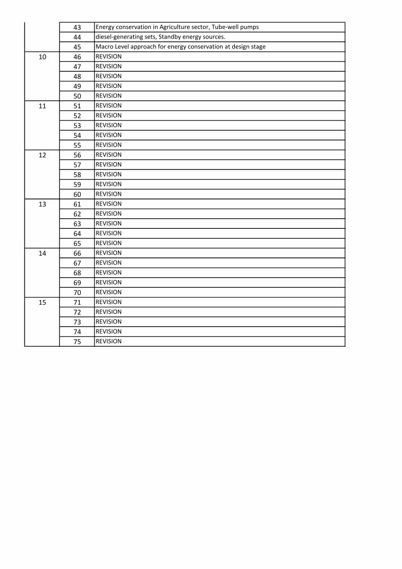
43 Energy conservation in Agriculture sector, Tube-well pumps
44 diesel-generating sets, Standby energy sources.
45 Macro Level approach for energy conservation at design stage
46 REVISION
47 REVISION
48 REVISION
49 REVISION
50 REVISION
51 REVISION
52 REVISION
53 REVISION
54 REVISION
55 REVISION
56 REVISION
57 REVISION
58 REVISION
59 REVISION
60 REVISION
61 REVISION
62 REVISION
63 REVISION
64 REVISION
65 REVISION
66 REVISION
67 REVISION
68 REVISION
69 REVISION
70 REVISION
71 REVISION
72 REVISION
73 REVISION
74 REVISION
75 REVISION
14
15
10
11
12
13


LESSON PLAN
Name of Faculty : Mr. Ranbir Dahiya
Discipline : Electrical Engg.
Semester : 4th
Subject : Estimating & Costing
Work Load : 4 Theory
Week Practical
Day
Practicals
Topic
1
Purpose of estimating and costing, proforma for making estimates, preparation of materials
schedule, costing, price list, preparation of tender document (with 2-3 exercises), net price list
2
Purpose of estimating and costing, proforma for making estimates, preparation of materials
schedule, costing, price list, preparation of tender document (with 2-3 exercises), net price list
3
Purpose of estimating and costing, proforma for making estimates, preparation of materials
schedule, costing, price list, preparation of tender document (with 2-3 exercises), net price list
4
Purpose of estimating and costing, proforma for making estimates, preparation of materials
schedule, costing, price list, preparation of tender document (with 2-3 exercises), net price list
5
market survey, overhead charges, labour charges, electrical point method and fixed
percentage method, contingency, profit, purchase system, enquiries, comparative statements,
orders for supply, pay e t of ills. Te ders – its o stitue ts, fi alizatio , spe i e te der
6
market survey, overhead charges, labour charges, electrical point method and fixed
percentage method, contingency, profit, purchase system, enquiries, comparative statements,
orders for supply, pay e t of ills. Te ders – its o stitue ts, fi alizatio , spe i e te der
7
market survey, overhead charges, labour charges, electrical point method and fixed
percentage method, contingency, profit, purchase system, enquiries, comparative statements,
orders for supply, pay e t of ills. Te ders – its o stitue ts, fi alizatio , spe i e te der
8
market survey, overhead charges, labour charges, electrical point method and fixed
percentage method, contingency, profit, purchase system, enquiries, comparative statements,
orders for supply, pay e t of ills. Te ders – its o stitue ts, fi alizatio , spe i e te der
9
Types of wiring :
Cleat, batten, casing capping and conduit wiring, comparison of different wiring systems,
selection and design of wiring schemes for particular situation (domestic and Industrial)
10
Types of wiring :
Cleat, batten, casing capping and conduit wiring, comparison of different wiring systems,
selection and design of wiring schemes for particular situation (domestic and Industrial)
11
Types of wiring :
Cleat, batten, casing capping and conduit wiring, comparison of different wiring systems,
selection and design of wiring schemes for particular situation (domestic and Industrial)
12
Types of wiring :
Cleat, batten, casing capping and conduit wiring, comparison of different wiring systems,
selection and design of wiring schemes for particular situation (domestic and Industrial)
13Selection of wires and cables, wiring accessories and use of protective devices i.e. MCB, ELCB
etc. Use of wire-gauge and tables ( to be prepared/arranged)
3
1
2
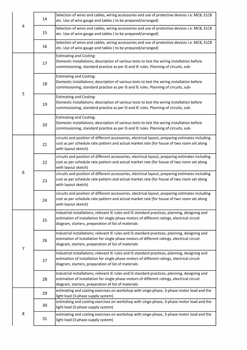
14Selection of wires and cables, wiring accessories and use of protective devices i.e. MCB, ELCB
etc. Use of wire-gauge and tables ( to be prepared/arranged)
15Selection of wires and cables, wiring accessories and use of protective devices i.e. MCB, ELCB
etc. Use of wire-gauge and tables ( to be prepared/arranged)
16Selection of wires and cables, wiring accessories and use of protective devices i.e. MCB, ELCB
etc. Use of wire-gauge and tables ( to be prepared/arranged)
17
Estimating and Costing:
Domestic installations; description of various tests to test the wiring installation before
commissioning, standard practice as per IS and IE rules. Planning of circuits, sub-
18
Estimating and Costing:
Domestic installations; description of various tests to test the wiring installation before
commissioning, standard practice as per IS and IE rules. Planning of circuits, sub-
19
Estimating and Costing:
Domestic installations; description of various tests to test the wiring installation before
commissioning, standard practice as per IS and IE rules. Planning of circuits, sub-
20
Estimating and Costing:
Domestic installations; description of various tests to test the wiring installation before
commissioning, standard practice as per IS and IE rules. Planning of circuits, sub-
21
circuits and position of different accessories, electrical layout, preparing estimates including
cost as per schedule rate pattern and actual market rate (for house of two room set along
with layout sketch)
22
circuits and position of different accessories, electrical layout, preparing estimates including
cost as per schedule rate pattern and actual market rate (for house of two room set along
with layout sketch)
23
circuits and position of different accessories, electrical layout, preparing estimates including
cost as per schedule rate pattern and actual market rate (for house of two room set along
with layout sketch)
24
circuits and position of different accessories, electrical layout, preparing estimates including
cost as per schedule rate pattern and actual market rate (for house of two room set along
with layout sketch)
25
Industrial installations; relevant IE rules and IS standard practices, planning, designing and
estimation of installation for single phase motors of different ratings, electrical circuit
diagram, starters, preparation of list of materials
26
Industrial installations; relevant IE rules and IS standard practices, planning, designing and
estimation of installation for single phase motors of different ratings, electrical circuit
diagram, starters, preparation of list of materials
27
Industrial installations; relevant IE rules and IS standard practices, planning, designing and
estimation of installation for single phase motors of different ratings, electrical circuit
diagram, starters, preparation of list of materials
28
Industrial installations; relevant IE rules and IS standard practices, planning, designing and
estimation of installation for single phase motors of different ratings, electrical circuit
diagram, starters, preparation of list of materials
29estimating and costing exercises on workshop with singe-phase, 3-phase motor load and the
light load (3-phase supply system)
30estimating and costing exercises on workshop with singe-phase, 3-phase motor load and the
light load (3-phase supply system)
31estimating and costing exercises on workshop with singe-phase, 3-phase motor load and the
light load (3-phase supply system)
7
8
4
5
6
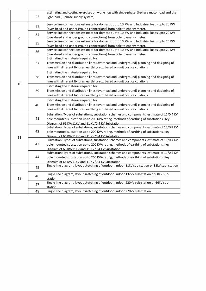
32estimating and costing exercises on workshop with singe-phase, 3-phase motor load and the
light load (3-phase supply system)
33Service line connections estimate for domestic upto 10 KW and Industrial loads upto 20 KW
(over-head and under ground connections) from pole to energy meter.
34Service line connections estimate for domestic upto 10 KW and Industrial loads upto 20 KW
(over-head and under ground connections) from pole to energy meter.
35Service line connections estimate for domestic upto 10 KW and Industrial loads upto 20 KW
(over-head and under ground connections) from pole to energy meter.
36Service line connections estimate for domestic upto 10 KW and Industrial loads upto 20 KW
(over-head and under ground connections) from pole to energy meter.
37
Estimating the material required for:
Transmission and distribution lines (overhead and underground) planning and designing of
lines with different fixtures, earthing etc. based on unit cost calculations
38
Estimating the material required for:
Transmission and distribution lines (overhead and underground) planning and designing of
lines with different fixtures, earthing etc. based on unit cost calculations
39
Estimating the material required for:
Transmission and distribution lines (overhead and underground) planning and designing of
lines with different fixtures, earthing etc. based on unit cost calculations
40
Estimating the material required for:
Transmission and distribution lines (overhead and underground) planning and designing of
lines with different fixtures, earthing etc. based on unit cost calculations
41Substation: Types of substations, substation schemes and components, estimate of 11/0.4 KV
pole mounted substation up to 200 KVA rating, methods of earthing of substations, Key
Diagram of 66 KV/11KV and 11 KV/0.4 KV Substation
42Substation: Types of substations, substation schemes and components, estimate of 11/0.4 KV
pole mounted substation up to 200 KVA rating, methods of earthing of substations, Key
Diagram of 66 KV/11KV and 11 KV/0.4 KV Substation
43Substation: Types of substations, substation schemes and components, estimate of 11/0.4 KV
pole mounted substation up to 200 KVA rating, methods of earthing of substations, Key
Diagram of 66 KV/11KV and 11 KV/0.4 KV Substation
44Substation: Types of substations, substation schemes and components, estimate of 11/0.4 KV
pole mounted substation up to 200 KVA rating, methods of earthing of substations, Key
Diagram of 66 KV/11KV and 11 KV/0.4 KV Substation
45Single line diagram, layout sketching of outdoor, indoor 11kV sub-station or 33kV sub- station
46Single line diagram, layout sketching of outdoor, indoor 132kV sub-station or 60kV sub-
station
47Single line diagram, layout sketching of outdoor, indoor 220kV sub-station or 66kV sub-
station
48 Single line diagram, layout sketching of outdoor, indoor 220kV sub-station.
12
9
10
11
LESSON PLAN
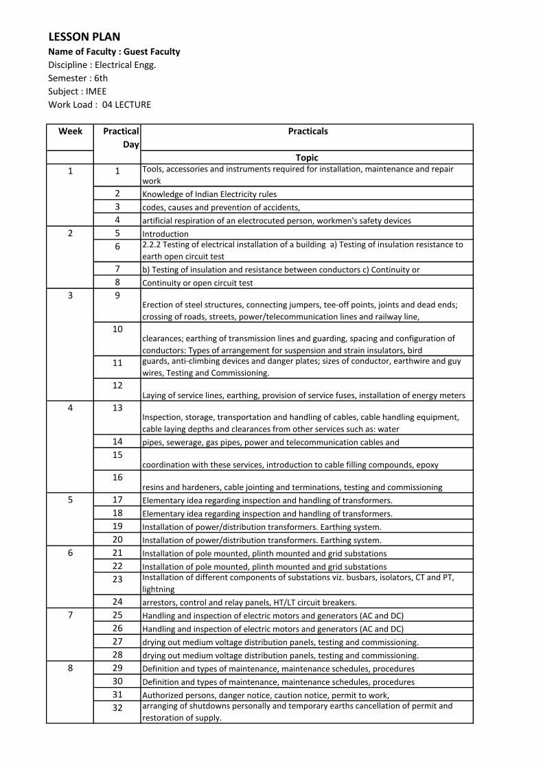
Name of Faculty : Guest Faculty
Discipline : Electrical Engg.
Semester : 6th
Subject : IMEE
Work Load : 04 LECTURE
Week Practical
Day
Practicals
Topic
1 Tools, accessories and instruments required for installation, maintenance and repair
work
2 Knowledge of Indian Electricity rules
3 codes, causes and prevention of accidents,
4 artificial respiration of an electrocuted person, workmen's safety devices
5 Introduction
6 2.2.2 Testing of electrical installation of a building a) Testing of insulation resistance to
earth open circuit test
7 b) Testing of insulation and resistance between conductors c) Continuity or
8 Continuity or open circuit test
9Erection of steel structures, connecting jumpers, tee-off points, joints and dead ends;
crossing of roads, streets, power/telecommunication lines and railway line,
10clearances; earthing of transmission lines and guarding, spacing and configuration of
conductors: Types of arrangement for suspension and strain insulators, bird
11 guards, anti-climbing devices and danger plates; sizes of conductor, earthwire and guy
wires, Testing and Commissioning.
12Laying of service lines, earthing, provision of service fuses, installation of energy meters
13Inspection, storage, transportation and handling of cables, cable handling equipment,
cable laying depths and clearances from other services such as: water
14 pipes, sewerage, gas pipes, power and telecommunication cables and
15coordination with these services, introduction to cable filling compounds, epoxy
16resins and hardeners, cable jointing and terminations, testing and commissioning
17 Elementary idea regarding inspection and handling of transformers.
18 Elementary idea regarding inspection and handling of transformers.
19 Installation of power/distribution transformers. Earthing system.
20 Installation of power/distribution transformers. Earthing system.
21 Installation of pole mounted, plinth mounted and grid substations
22 Installation of pole mounted, plinth mounted and grid substations
23 Installation of different components of substations viz. busbars, isolators, CT and PT,
lightning
24 arrestors, control and relay panels, HT/LT circuit breakers.
25 Handling and inspection of electric motors and generators (AC and DC)
26 Handling and inspection of electric motors and generators (AC and DC)
27 drying out medium voltage distribution panels, testing and commissioning.
28 drying out medium voltage distribution panels, testing and commissioning.
29 Definition and types of maintenance, maintenance schedules, procedures
30 Definition and types of maintenance, maintenance schedules, procedures
31 Authorized persons, danger notice, caution notice, permit to work,
32 arranging of shutdowns personally and temporary earths cancellation of permit and
restoration of supply.
6
7
8
1
2
3
4
5

33 Patrolling and visual inspection of lines - points to be noted during patrolling from
ground; special inspections and night inspections;
34 Location of faults using Meggar, effect of open or loose neutral connections
35 provision of proper fuses on service lines and their effect on system, causes of dim and
flickering lights.
36 Maintenance schedule of transmission and distribution system.
37 Transformer maintenance and points to be attended to in respect of various items of
equipmen
38 Transformer maintenance and points to be attended to in respect of various items of
equipmen
39 Checking of insulation resistance, transformer oil level BDV test of oil and
40 measurement of earth resistance
41 Maintenance schedule of distribution transformers
42 Maintenance schedule of distribution transformers
43Checking and maintenance of busbars, isolating switches, HT/LT circuit breakers,
44 LT switches. Power transformers
45 Maintenance schedule of grid substation
46 Maintenance schedule of grid substation
47 Maintenance schedule of grid substation
48Over hauling of motors, preventive maintenance, trouble shooting of electric motors
49Over hauling of motors, preventive maintenance, trouble shooting of electric motors
50Over hauling of motors, preventive maintenance, trouble shooting of electric motors
51Over hauling of motors, preventive maintenance, trouble shooting of electric motors
52 Maintenance schedule of AC and DC motors
53 Maintenance schedule of AC and DC motors
54 Maintenance schedule of AC and DC motors
55 Maintenance schedule of AC and DC motors
56 Maintenance schedule of AC and DC motors
14
9
10
11
12
13

LESSON PLAN
Name of Faculty : Mrs. Preeti Girdhar (THEORY & PRACTICAL)
Discipline : Electrical Engg.
Semester : 4th
Subject : Instrumentation
Work Load : THEORY -03, PRACTICAL -2
Week Theory Week Practicals
(Including Assignments and Tests) Topic
1MEASUREMENTS- IMPROTANCE OF MEASUREMENTS BASIC MEASURING SYSTEM
TO MEASURE THE LEVEL OF A LIQUID USING A
TRANSDUCER
2ADVANTAGES & LIMITATIONS OFEACH MEASURING SYSTEMS AND DISPLAY DEVICES
3 TRANSDUCERS , THEORY
4 CONSTRUCTION & USE OF VARIOUS TRANSUDCERS LIKE RESISTANCE INDUCTANCE
& CAPACITANCE. TO MEASURE TEMPERATURE USING A THERMOCOUPLE
5 CONST- A USE OF ELECTROMEGNETIC PIEZO ELECTRIC TYPE.
6 MEASUREMENTS OF DISPLACEMENT AND STRAIN- DISPLACEMENT MEASURING
DEVICES, WIRE WOUND, POTENTIOMETER, LVDT
7STAIN GUAGE & THEIR DIFIFCULT TYPE STUDY AND USE OF DIGITAL TEMPERATURE CONTROLLER
8 RESISTANCE TYPE, WIRE AND FOIL TYPE ETC.
9 GAUGE FACTOR, GAUGE MATERIALS AND THEIR SELECTIONS
10 USE OF ELECTRICAL STAIN GAUGES USE OF THERMISTOR IN ON/OFF TRANSDUCER
11 STRAIN GUAGE BRIDGES
12 AMPLIFIERS & ASSIGNMENTS BASED IB AVIVE TIOUCS
13 FORCE AND TORQUE MEASUREMENTS- DIFFERENT TYPES OF FORCE MEASURING
DEVICES AND THEIR PRINCIPLES. STUDY OF VARIABLE CAPACITANCE TRANSDUCER
14 LOAD MEASUREMENTS BY USING PELASTIC TRANSDUCERS
15 BY ELECTRICAL STRAIN GUAGES
16 LOAD CELLS DRAW THE CHARACTERSITICS OF A POTENTIOMETER
17 MEASUREMENT OF TONQUE BY BROKE DYNAMOMETER, ELECTRICAL STAIN
GUAGES
18 DIFFERENT METHODS & DEVICES OF SPEED MEASUREMENTS
19 PRESSURE MEASUREMENT- BOUNON PRESSURE GUAGES ELECTRICAL PRESSURE
PICK UPS TO MEASURE THE LINE OR DISPLACEMENT USING LVDT
20 PRINCIPLE OF ELECTRICAL PRESSURE PICK UPS & THEIR PRINCIPLE
21 CONSTRUCTION & APPLICATIONAL OF PICK UPS. USE OF PRESSURE CELLS
Practical
Day
11
2
3
Lecture
day
4
5
6
7
2
3
4
5
6
7
TO MEASURE THE LEVEL OF A LIQUID USING A
TRANSDUCER
TO MEASURE TEMPERATURE USING A THERMOCOUPLE
STUDY AND USE OF DIGITAL TEMPERATURE CONTROLLER
USE OF THERMISTOR IN ON/OFF TRANSDUCER
STUDY OF VARIABLE CAPACITANCE TRANSDUCER
DRAW THE CHARACTERSITICS OF A POTENTIOMETER
TO MEASURE THE LINE OR DISPLACEMENT USING LVDT
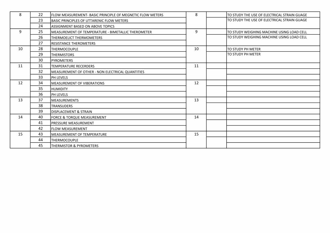
22 FLOW MEASUREMENT- BASIC PRINCIPLE OF MEGNETIC FLOW METERS TO STUDY THE USE OF ELECTRICAL STRAIN GUAGE
23 BASIC PRINCIPLES OF UTTARENIC FLOW METERS
24 ASSIGNMENT BASED ON ABOVE TOPICS
25 MEASUREMENT OF TEMPERATURE - BIMETALLIC THEROMETER TO STUDY WEIGHING MACHINE USING LOAD CELL
26 THERMOELICT THERMOMETERS
27 RESISTANCE THEROMETERS
28 THERMOCOUPLE TO STUDY PH METER
29 THERMISTORS
30 PYROMETERS
31 TEMPERATURE RECERDERS
32 MEASUREMENT OF OTHER - NON ELECTRICAL QUANTITIES
33 PH LEVELS
34 MEASUREMENT OF VIBERATIONS
35 HUMIDITY
36 PH LEVELS
37 MEASUREMENTS
38 TRANSUDERS
39 DISPLACEMENT & STRAIN
40 FORCE & TORQUE MEASUREMENT
41 PRESSURE MEASUREMENT
42 FLOW MEASUREMENT
43 MEASUREMENT OF TEMPERATURE
44 THERMOCOUPLE
45 THERMISTOR & PYROMETERS
8
9
10
11
12
13
14
15
8
9
10
11
12
13
14
15
TO STUDY THE USE OF ELECTRICAL STRAIN GUAGE
TO STUDY WEIGHING MACHINE USING LOAD CELL
TO STUDY PH METER

Week Practicals
Topic
1 INTRODUCTION
2 MAKING GROUP
3 STUDY OF DIFFERENT TYPE OF PROJECTS
4 STUDY OF DIFFERENT TYPE OF PROJECTS
5 CHOOSE MAJOR PROJECTS
6 CHOOSE MAJOR PROJECTS
7 MAKE BLOCK DIAGRAM OF MAJOR PROJECT
8 MAKE EVERY SECTION DRAWING / SKETCH
9 MAKE CIRCUIT DIAGRAM OF EACH SECTION
10 MAKE CIRCUIT DIAGRAM OF EACH SECTION
11 MAKE MATERIAL LIST WITH SPECIFICATION & QUANTITY
12 PURCHASES OF MATERIAL
13 PURCHASES OF MATERIAL
14 FABRICATION WORKS
15 FABRICATION WORKS
16 FABRICATION WORKS
17 FABRICATION WORKS
18 MAKING WIRING ACCORDING TO CIRCUIT DIAGRAM
19 MAKING WIRING ACCORDING TO CIRCUIT DIAGRAM
20 MAKING WIRING ACCORDING TO CIRCUIT DIAGRAM
21 CHECK THE PROJECT AND FAULT FINDING
22 CHECK THE PROJECT AND FAULT FINDING
23 RECTIFY THE FAULTS
24 RECHECKING THE PROJECTS
25 CHECK THE REPORT
26 ASSESMENT OF STUDENTS
27 ASSESMENT OF STUDENTS
28 ASSESMENT OF STUDENTS
29 ASSESMENT OF STUDENTS
15 30 ASSESMENT OF STUDENTS
7
2
LESSON PLAN
Name of Faculty : Ved Parkash
Discipline : Electrical Engg.
Semester : 6th
Subject : Major project (Practical)
Work Load : Practicals 06
Practical
Day
1
3
4
5
6
13
14
8
9
10
11
12


Week Theory Week Practicals
(Including Assignments and Tests) Topic
1What is PLC, concept of PLC
G-1Components/sub-components of a PLC, Learning functions
of different modules of a PLC system
2Building blocks of PLC, Functions of various blocks
3 limitations of relays. Advantages of PLCs over electromagnetic relays.
4 Different programming languages, PLC manufacturer etc.
5Basic operation and principles of PLC
G-1Practical steps in programming a PLC (a) using a Hand held
programmer
6
7
8
9 Basic instructions like latch, master control self holding relays. G-1 (b) using computer interface
10 Timer instruction like retentive timers, resetting of timers
11Counter instructions like up counter, down counter, resetting of
counters.
12 Arithmetic Instructions (ADD,SUB,DIV,MUL etc.)
13MOV instruction
G-1Introduction to step 5 programming language, ladder
diagram concepts, instruction list syntax
14 RTC(Real Time Clock Function)
15Comparison instructions like equal, not equal, greater, greater than
equal, less than, less than equa
16 Programming based on basic instructions
17timer, counter
G-1Introduction to step 5 programming language, ladder
diagram concepts, instruction list syntax
18sequencer, and comparison instructions using ladder program.
19 Assembly
20 Packaging -
21 Process controls G-1 Basic logic operations, AND, OR, NOT functions
22 Car parking - 6
1
2
3
4
5
Lecture
day
Practical
Day
LESSON PLAN
Name of Faculty : SH. MAHENDER KAUSHIK
Discipline : Electrical Engg.
Semester : 6TH
Subject : PLC & MICROCONTROLLER
Work Load : (THEORY- 4) (Practical-3)
1
2
3
4
5
6
Components/sub-components of a PLC, Learning functions
of different modules of a PLC systemG-2
G-2
Practical steps in programming a PLC (a) using a Hand held
programmer
G-2
(b) using computer interface
G-2
Introduction to step 5 programming language, ladder
diagram concepts, instruction list syntax
G-2
Introduction to step 5 programming language, ladder
diagram concepts, instruction list syntax
G-2
Basic logic operations, AND, OR, NOT functions
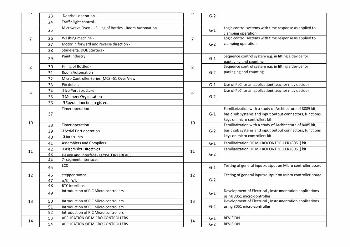
23 Doorbell operation -
24 Traffic light control -
25Microwave Oven - - Filling of Bottles - Room Automation
G-1Logic control systems with time response as applied to
clamping operation
26 Washing machine -
27 Motor in forward and reverse direction -
28 Star-Delta, DOL Starters -
29Paint Industry
G-1Sequence control system e.g. in lifting a device for
packaging and counting
30 Filling of Bottles -
31 Room Automation
32 Micro Controller Series (MCS)-51 Over View
33 Pin details G-1 Use of PLC for an application( teacher may decide)
34
35
36
37
Timer operation
G-1
Familiarization with a study of Architecture of 8085 kit,
basic sub systems and input output connectors, functions
keys on micro controllers kit
38 Timer operation
39
40
41 Assemblers and Compilers G-1 Familiarization OF MICROCONTROLLER (8051) kit
42
43 Design and Interface- KEYPAD INTERFACE
44 7- segment interface,
45LCD
G-1Testing of general input/output on Micro controller board
46 stepper motor
47 A/D, D/A,
48 RTC interface.
49Introduction of PIC Micro controllers
G-1Development of Electrical , Instrumentation applications
using 8051 micro-controller
50 Introduction of PIC Micro controllers
51 Introduction of PIC Micro controllers
52 Introduction of PIC Micro controllers
53 APPLICATION OF MICRO CONTROLLERS G-1 REVISION
54 APPLICATION OF MICRO CONTROLLERS G-2 REVISION
6
13
7
8
9
10
11
14
12
13
14
6
7
8
9
10
11
12
G-2
G-2
Logic control systems with time response as applied to
clamping operation
G-2
Sequence control system e.g. in lifting a device for
packaging and counting
G-2
Use of PLC for an application( teacher may decide)
G-2
Development of Electrical , Instrumentation applications
using 8051 micro-controller
G-2
Familiarization with a study of Architecture of 8085 kit,
basic sub systems and input output connectors, functions
keys on micro controllers kit
G-2
Familiarization OF MICROCONTROLLER (8051) kit
G-2
Testing of general input/output on Micro controller board

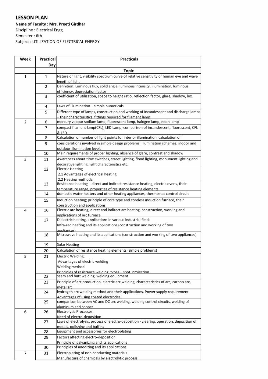
LESSON PLAN
Name of Faculty : Mrs. Preeti Girdhar
Discipline : Electrical Engg.
Semester : 6th
Subject : UTILIZATION OF ELECTRICAL ENERGY
Week Practical
Day
Practicals
Topic
1 Nature of light, visibility spectrum curve of relative sensitivity of human eye and wave
length of light
2 Definition: Luminous flux, solid angle, luminous intensity, illumination, luminous
efficiency, depreciation factor
3 coefficient of utilization, space to height ratio, reflection factor, glare, shadow, lux.
4 La s of illu i atio – si ple u e i als5 Different type of lamps, construction and working of incandescent and discharge lamps
– thei ha a te isti s, fitti gs e ui ed fo fila e t la p6 mercury vapour sodium lamp, fluorescent lamp, halogen lamp, neon lamp
7 compact filament lamp(CFL), LED Lamp, comparison of incandescent, fluorescent, CFL
& LED
8 Calculation of number of light points for interior illumination, calculation of
illumination at different points9 considerations involved in simple design problems. Illumination schemes; indoor and
outdoor illumination levels
10 Main requirements of proper lighting; absence of glare, contrast and shadow
11 Awareness about time switches, street lighting, flood lighting, monument lighting and
decorative lighting, light characteristics etc.
12 Electric Heating
2.1 Advantages of electrical heating
2.2 Heating methods:
13 Resista e heati g – di e t a d i di e t esista e heati g, ele t i o e s, thei temperature range, properties of resistance heating elements
14 domestic water heaters and other heating appliances, thermostat control circuit
15 Induction heating; principle of core type and coreless induction furnace, their
construction and applications
16 Electric arc heating; direct and indirect arc heating, construction, working and
applications of arc furnace
17 Dielectric heating, applications in various industrial fields
Infra-red heating and its applications (construction and working of two
appliances)
18 Microwave heating and its applications (construction and working of two appliances)
19 Solar Heating
20 Calculation of resistance heating elements (simple problems)
21 Electric Welding:
Advantages of electric welding
Welding method
P i iples of esista e eldi g, types – spot, p oje tio22 seam and butt welding, welding equipment
23 Principle of arc production, electric arc welding, characteristics of arc; carbon arc,
metal arc
24 hydrogen arc welding method and their applications. Power supply requirement.
Advantages of using coated electrodes
25 comparison between AC and DC arc welding, welding control circuits, welding of
aluminum and copper
26 Electrolytic Processes:
Need of electro-deposition
27 Laws of electrolysis, process of electro-deposition - clearing, operation, deposition of
metals, polishing and buffing
28 Equipment and accessories for electroplating
29 Factors affecting electro-deposition
Principle of galvanizing and its applications
30 Principles of anodizing and its applications
31 Electroplating of non-conducting materials
Manufacture of chemicals by electrolytic process
6
1
2
3
4
5
7
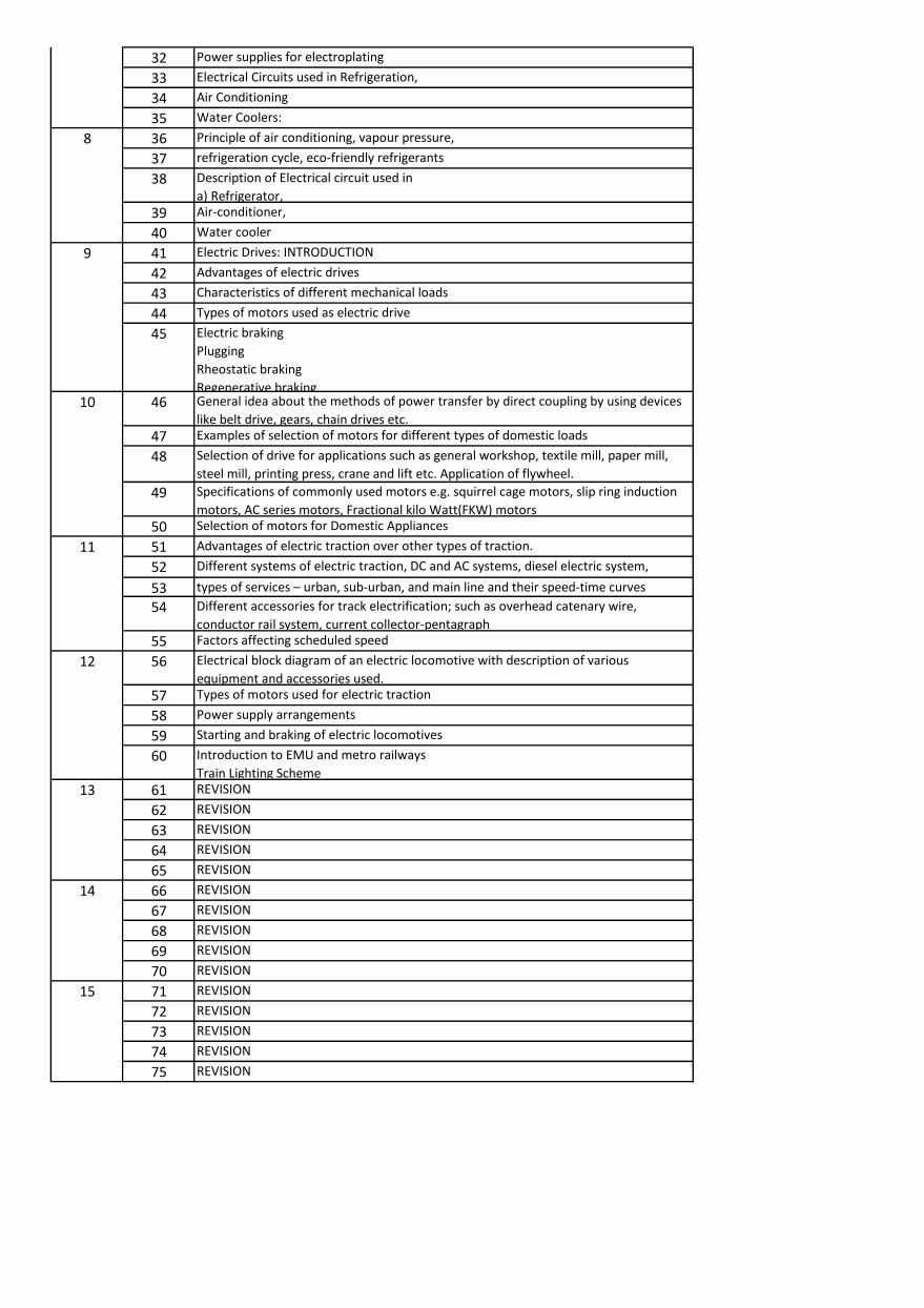
32 Power supplies for electroplating
33 Electrical Circuits used in Refrigeration,
34 Air Conditioning
35 Water Coolers:
36 Principle of air conditioning, vapour pressure,
37 refrigeration cycle, eco-friendly refrigerants
38 Description of Electrical circuit used in
a) Refrigerator,
39 Air-conditioner,
40 Water cooler
41 Electric Drives: INTRODUCTION
42 Advantages of electric drives
43 Characteristics of different mechanical loads
44 Types of motors used as electric drive
45 Electric braking
Plugging
Rheostatic braking
Regenerative braking46 General idea about the methods of power transfer by direct coupling by using devices
like belt drive, gears, chain drives etc.
47 Examples of selection of motors for different types of domestic loads
48 Selection of drive for applications such as general workshop, textile mill, paper mill,
steel mill, printing press, crane and lift etc. Application of flywheel.
49 Specifications of commonly used motors e.g. squirrel cage motors, slip ring induction
motors, AC series motors, Fractional kilo Watt(FKW) motors
50 Selection of motors for Domestic Appliances
51 Advantages of electric traction over other types of traction.
52 Different systems of electric traction, DC and AC systems, diesel electric system,
53 types of se i es – u a , su -u a , a d ai li e a d thei speed-ti e u es54 Different accessories for track electrification; such as overhead catenary wire,
conductor rail system, current collector-pentagraph
55 Factors affecting scheduled speed
56 Electrical block diagram of an electric locomotive with description of various
equipment and accessories used.
57 Types of motors used for electric traction
58 Power supply arrangements
59 Starting and braking of electric locomotives
60 Introduction to EMU and metro railways
Train Lighting Scheme
61 REVISION
62 REVISION
63 REVISION
64 REVISION
65 REVISION
66 REVISION
67 REVISION
68 REVISION
69 REVISION
70 REVISION
71 REVISION
72 REVISION
73 REVISION
74 REVISION
75 REVISION
13
14
15
8
9
10
11
12