Lecture 2-1. Basic circuit elements
Yoonkey Nam

How do we use circuit models
in bioengineering field?

Excitable cell membrane model
3
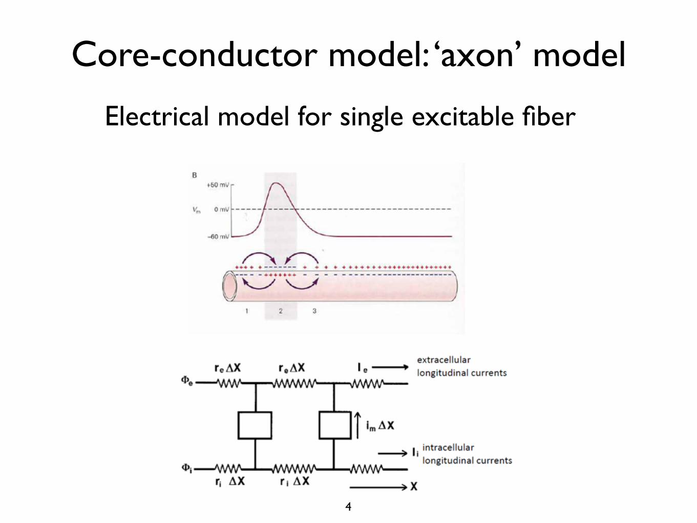
Core-conductor model: ‘axon’ model
Electrical model for single excitable fiber
4

Electrical stimulation of excitable cells
5
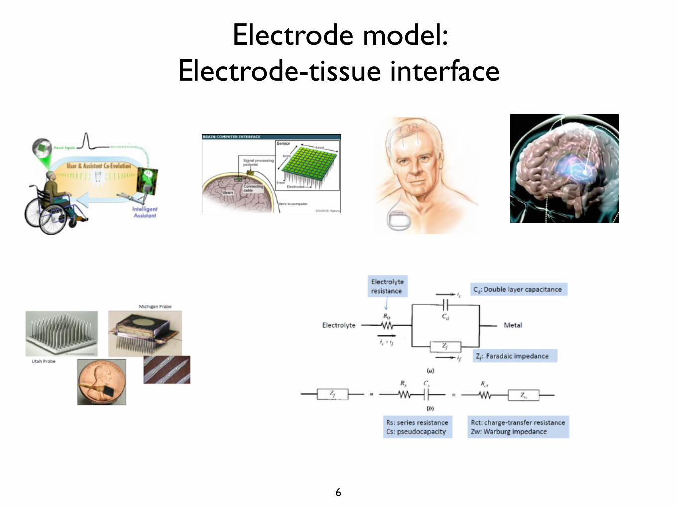
Electrode model: Electrode-tissue interface
6

Instrumentation systems
7
Sensor Analog circuits
Analog-to-digital converter (ADC)
Digital signal processing (DSP)Display
Data storage
LAN
Control & Feedback
Biological system
Body
Tissue
Cell
Biomolecules
Digital-to-analog converter (DAC)

Instrumentation for ‘measurement’
sensor
signal amplifier
signal filter
DSP / Display
Brain / neurons
DAQ
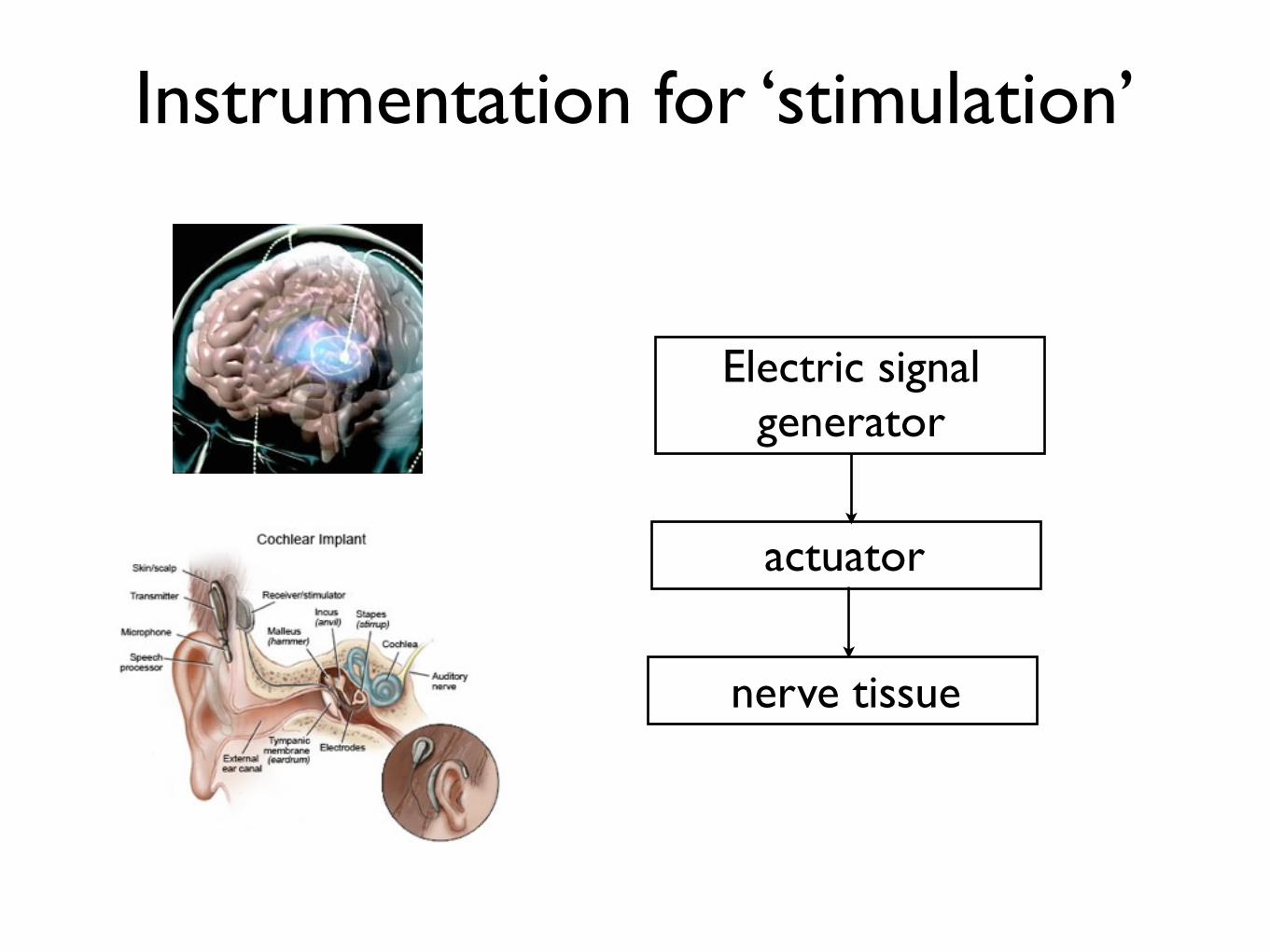
Instrumentation for ‘stimulation’
actuator
nerve tissue
Electric signal generator

Both cases (measurement & stimulation) can be further generalized
sensor
signal amplifier
signal filter
computer display
Brain / neurons
actuator
nerve tissue
Electric signal generator
Try to divide into two parts ...

Two big parts: Source vs. Load
signal or energy generating or supplying
parts
signal or energy receiving or consuming
parts
signal or energy flow

Can you model the following cases with sources and loads?

Bioinstrumentation model Source vs. Load
signal or energy generating or supplying
parts
signal or energy receiving or consuming
parts
signal or energy flow Pulse
generator (source)
nerve tissue (load)

Some examples
• Signal source and receiving or processing load
- Voice amplifying microphone system
- In ECG monitoring system, body is a ECG signal source and
amplifier/filter and display units are signal processing load
• Energy source and consuming load
- MP3 player circuits and battery
- Power plant and buildings
- Beating heart and blood vessel network
- In DBS system, electrical pulse generator is delivering
sufficient electrical energy (‘source’) to the surrounding nerve
tissues (‘load’) which consumes the energy
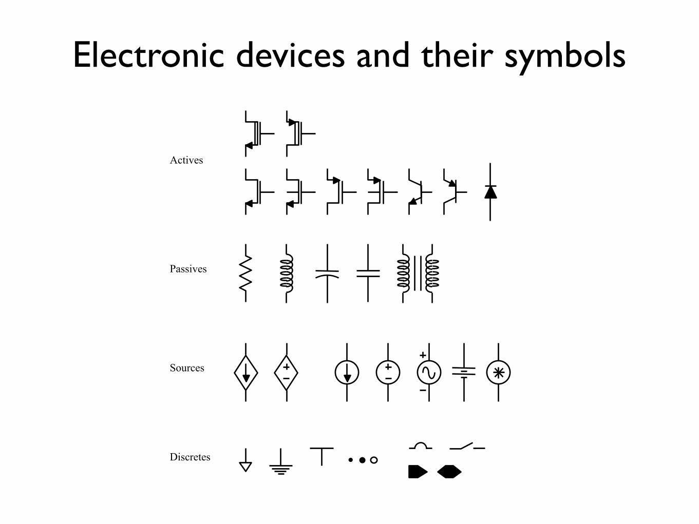
Electronic devices and their symbols
Actives
Passives
Sources
Discretes
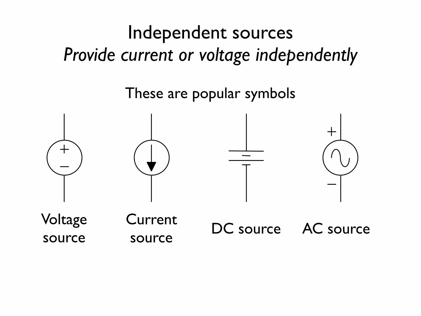
Independent sources Provide current or voltage independently
Voltage source
Current source DC source AC source
These are popular symbols
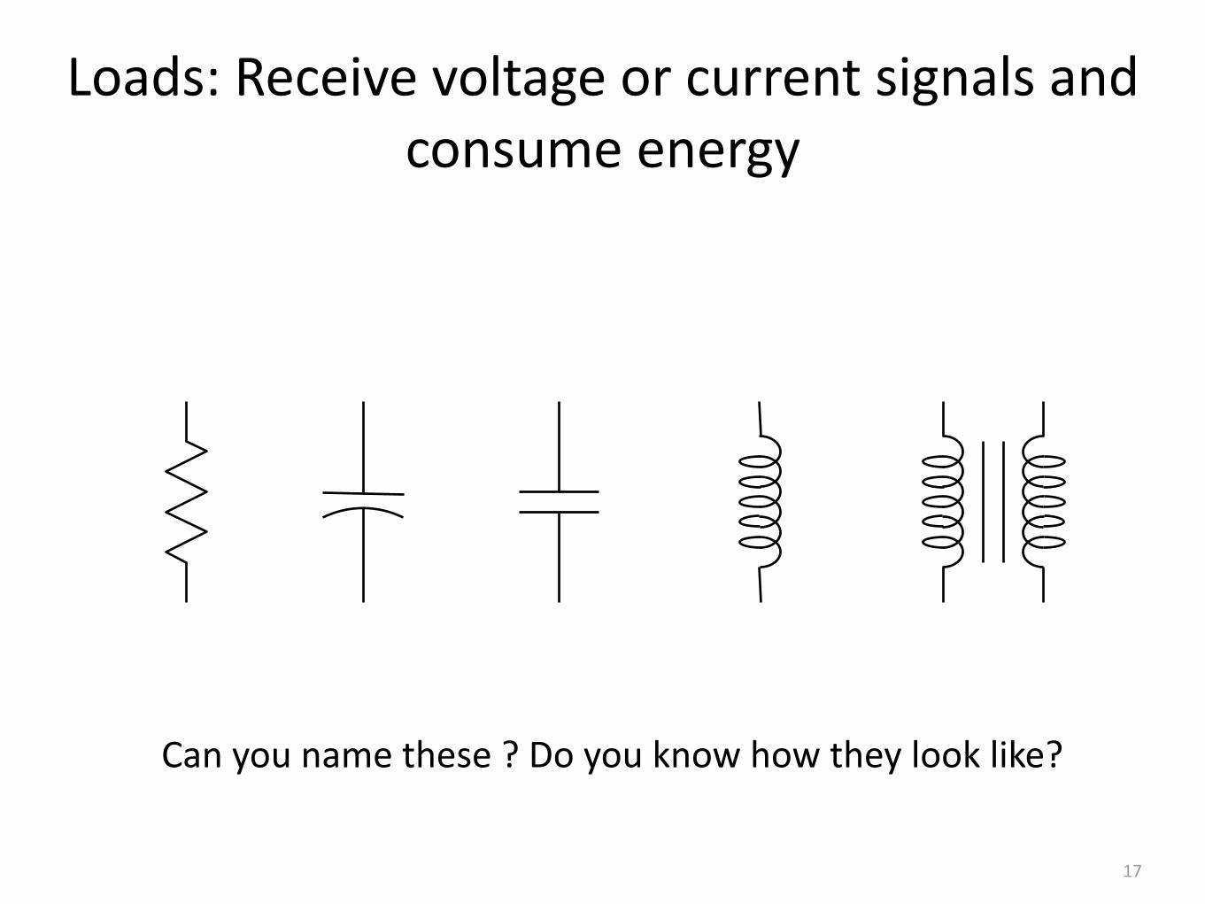
Loads: Receive voltage or current signals and consume energy
17
Can you name these ? Do you know how they look like?


A generic two-terminal network element
Terminal 1
Terminal 2
i(t)
v(t) = v(terminal 1) - v(terminal 2)
+
-
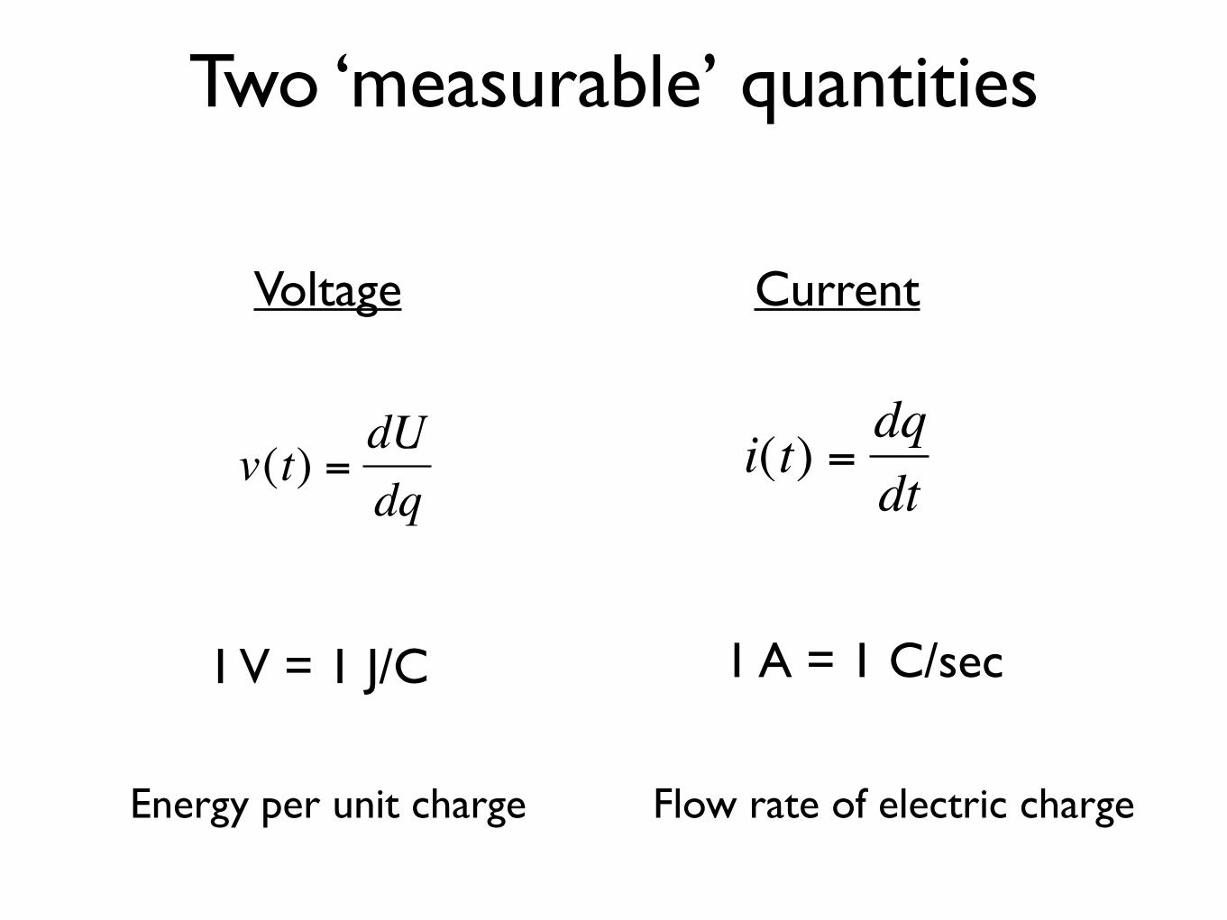
Two ‘measurable’ quantities
Voltage Current
€
v(t) =dUdq
€
i(t) =dqdt
1 V = 1 J/C 1 A = 1 C/sec
Energy per unit charge Flow rate of electric charge
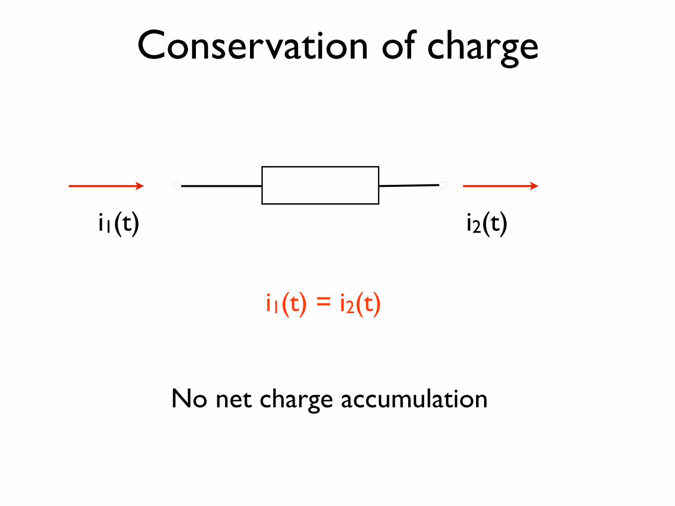
Conservation of charge
i1(t) i2(t)
i1(t) = i2(t)
No net charge accumulation

Voltage and current sign convention
i(t)
+ !
v(t) !
-+ 3A
a
b
+ 3A is flowing from a to b
= - 3A is flow from b to a
Remember the sign convention

Remember the sign convention
i(t)
+ !
v(t) !
-
a
b
vab = + v(t)
iab = + i(t)
If you write the voltage between a and b as
then the resulting current convention should be
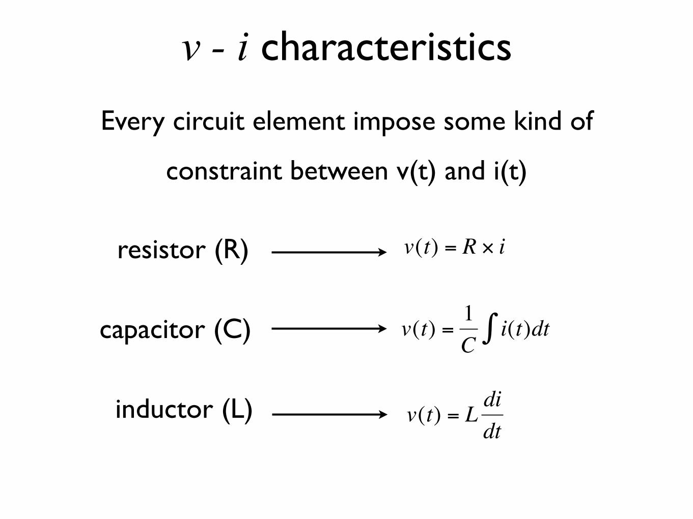
v - i characteristics
Every circuit element impose some kind of
constraint between v(t) and i(t)
resistor (R)
capacitor (C)
inductor (L)
€
v(t) = R × i
€
v(t) =1C
i(t)dt∫
€
v(t) = L didt

More complicated devices Transistor: Three terminal device !
+ VCE
-
(Collector)
(Emitter)
(Base)
VBE
+
-
IC
IE
IB
IC = β IB
IC = α IE
VBE > 0.7 (V)
(Collector)
(Emitter)
(Base)
First, define v and i Second, write a device equations

Circuit elements, symbols, v-i relation
Resistor
Inductor
Capacitor
+ -
+ -
+ -
€
v(t) = R × i(t)
€
v(t) = L didt
€
i(t) = C dvdt
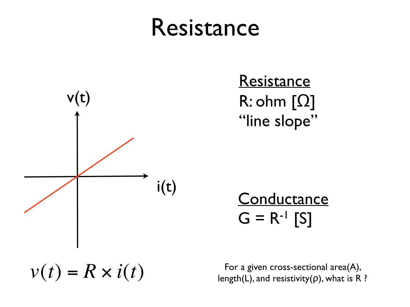
Resistance
v(t)
i(t)
€
v(t) = R × i(t)
Resistance R: ohm [Ω] “line slope”
Conductance G = R-1 [S]
For a given cross-sectional area(A), length(L), and resistivity(ρ), what is R ?

Resistor
28
Figure 2–24 Typical fixed resistors.
Figure 2–27 Typical wirewound power resistors.
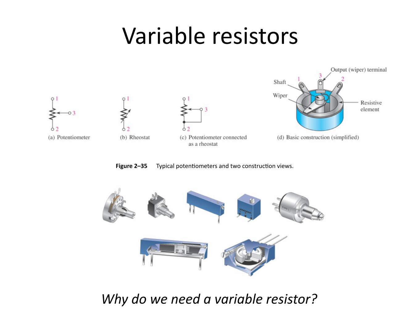
Figure 2–35 Typical potenDometers and two construcDon views.
Variable resistors
Why do we need a variable resistor?

Inductance
Current flow(i) at a coil induces flux(ψ) by magnetic field
ψ(t) = L x i(t)
L (inductance) : Henry [H]
€
v(t) =ddtψ(t) = L di
dt
When ‘time-varying’ current is applied, non-zero voltage can be induced
i(t)
+ !
v(t) !
-
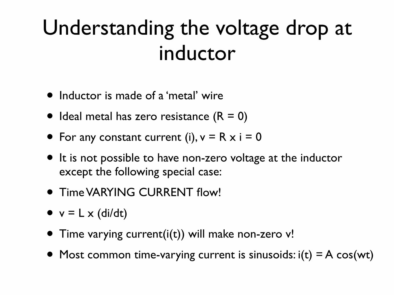
Understanding the voltage drop at inductor
• Inductor is made of a ‘metal’ wire
• Ideal metal has zero resistance (R = 0)
• For any constant current (i), v = R x i = 0
• It is not possible to have non-zero voltage at the inductor except the following special case:
• Time VARYING CURRENT flow!
• v = L x (di/dt)
• Time varying current(i(t)) will make non-zero v!
• Most common time-varying current is sinusoids: i(t) = A cos(wt)

Inductor
32
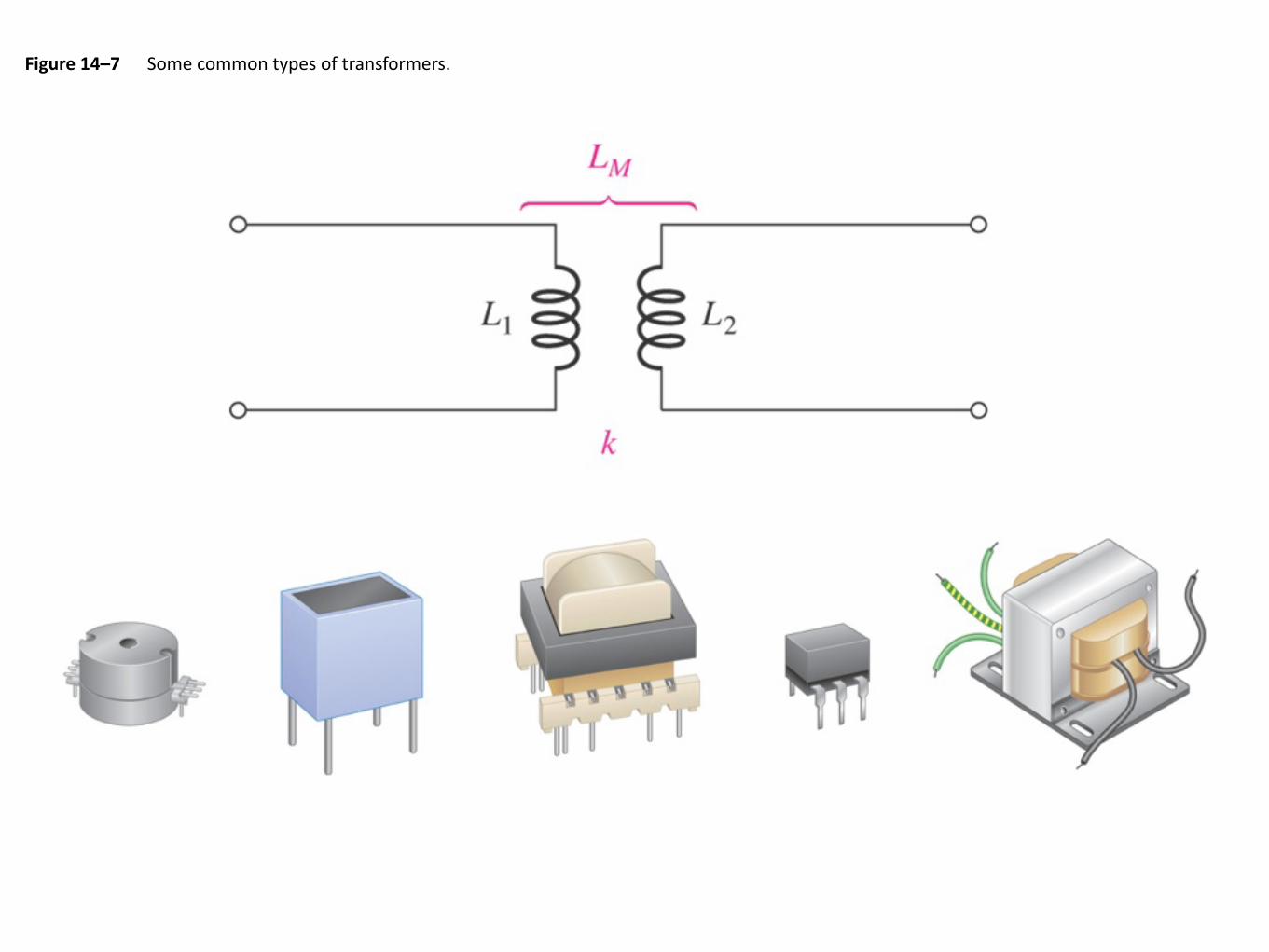
Figure 14–7 Some common types of transformers.

Capacitance
i(t)+ !
v(t) !-
€
i(t) =ddtQ = C dv
dt
€
C =QV
How much charge can be accumulated at a parallel metal plate separated by a dielectric, when a voltage is applied?
When ‘time varying’ voltage is applied, non-zero current can flow

Understanding the current flow at capacitor
• Capacitor is made of two metal plates ‘separate’ by insulating materials (dielectric material such as air)
• Ideal dielectric material has infinite resistance
• For any constant voltage (v), i = v / R = 0
• It is not possible to have non-zero current at the capacitor except the following special case:
• Time VARYING VOLTAGE!
• i = C x (dv/dt)
• Time varying voltage(v(t)) will make non-zero i!
• Most common time-varying voltage is sinusoids: v(t) = A cos(wt)
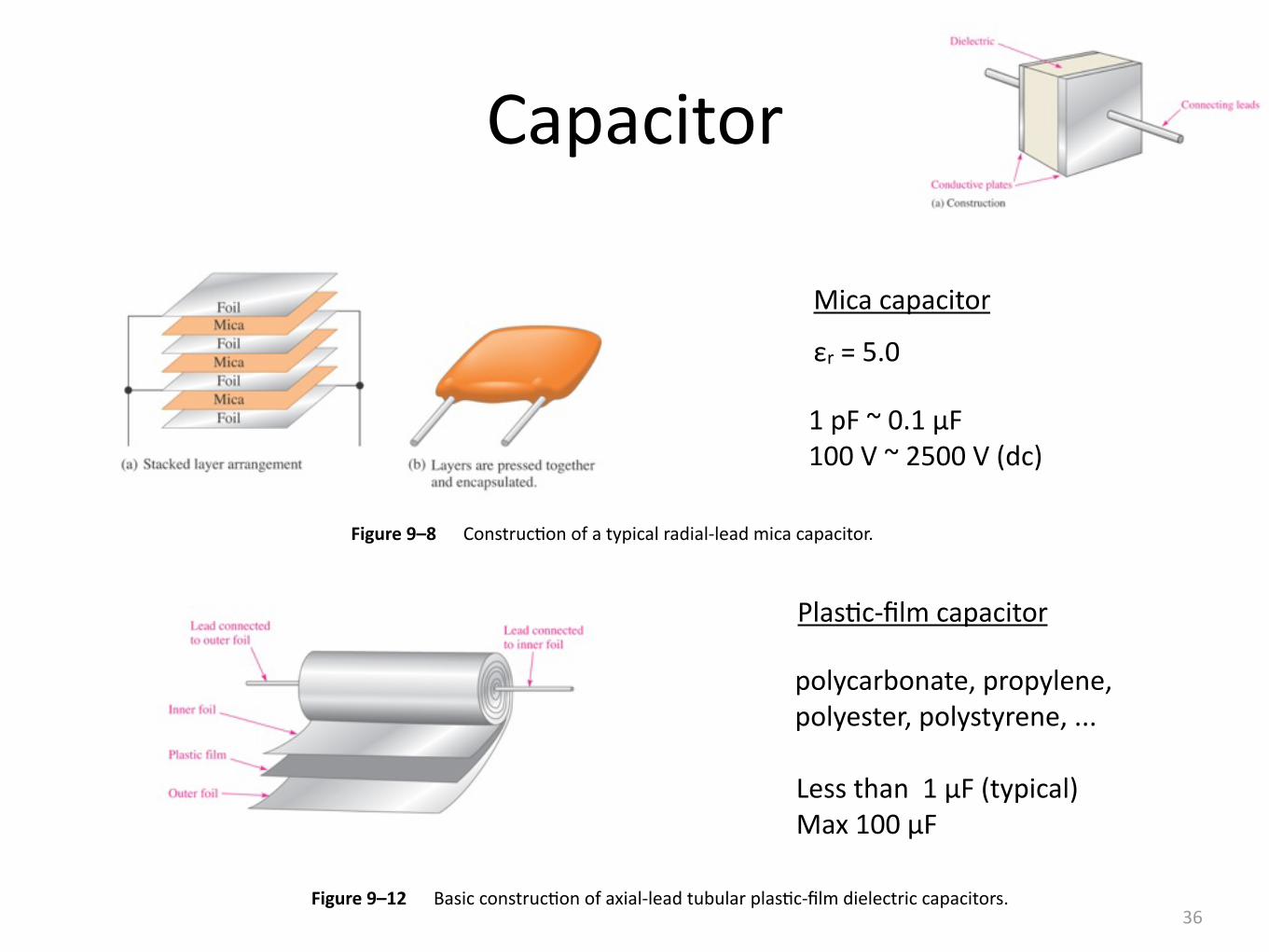
Capacitor
36Figure 9–12 Basic construcDon of axial-‐lead tubular plasDc-‐film dielectric capacitors.
1 pF ~ 0.1 μF 100 V ~ 2500 V (dc)
εr = 5.0
Figure 9–8 ConstrucDon of a typical radial-‐lead mica capacitor.
Less than 1 μF (typical) Max 100 μF
Mica capacitor
PlasDc-‐film capacitor
polycarbonate, propylene, polyester, polystyrene, ...

εr = 1200 1 pF ~ 2.2 μF Max 6000 V (dc)
Figure 9–10 Examples of ceramic capacitors.
Ceramic Capacitors
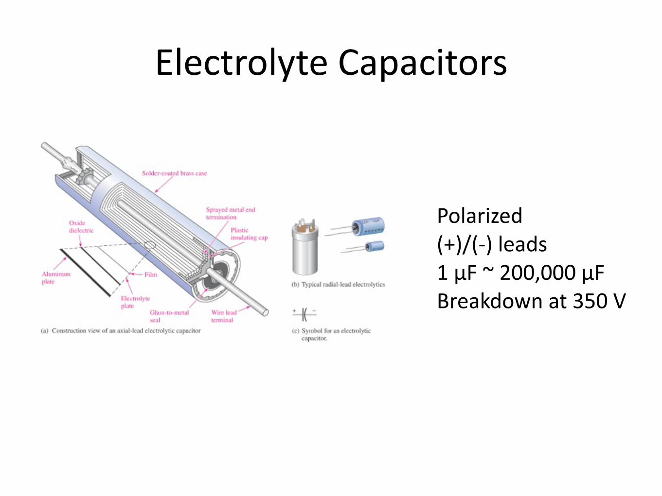
Electrolyte Capacitors
Polarized (+)/(-‐) leads 1 μF ~ 200,000 μF Breakdown at 350 V

Figure 9–17 Trimmer capacitors.
Variable capacitor

Comments on R, L, C• Resistor: v = R x i
• For a given terminal current, the voltage drop depends on the resistance
• Inductor: v = L x (di / dt)
• For a given time-varying current, the voltage drop depends on the inductance
• Capacitance : i = C (dv / dt)
• For a given time-varying voltage, the amount of current that flows in the terminal depends on the capacitance
• In one aspect, R, L, C all do similar thing!
• They determine the current or voltage of the element
• They determine(‘resist’ or ‘impede’) the current flow for a given voltage
• A strict concept of impedance will be introduced later in this course