8085 Architecture &8085 Architecture & Its Assembly language programming
Dr A SahuDept of Computer Science &
EngineeringEngineering IIT Guwahati

Outline
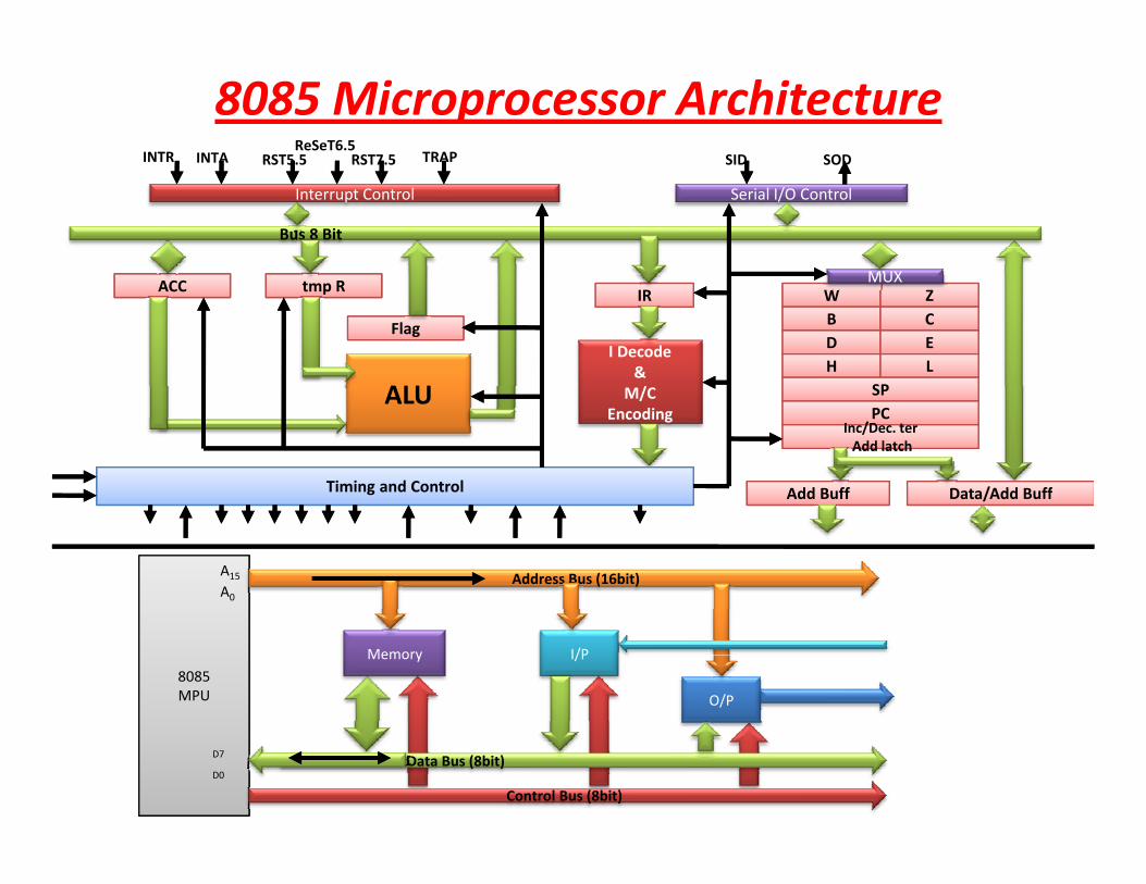
• 8085 – Block diagram (Data Path)
– Instruction Set of 8085
• Sample program of 8085
• Counter & Time DelayCounter & Time elay
• Stack and Sub Routine
• Assignment on 8085• Assignment on 8085
• Introduction to 8086 and 30x86 architecture
INTR INTA RST5.5ReSeT6.5
RST7.5 TRAP SID SOD
8085 Microprocessor Architecture
MUX
Bus 8 Bit
Interrupt Control Serial I/O Control
RST5.5 RST7.5 SID SOD
W ZB CD EH L
SP
MUXIR
I Decode& /
tmp RACC
ALU
Flag
SPPC
I /D tAdd latch
Inc/Dec. terAdd latch
M/CEncoding
Timing and Control
ALU
Add Buff Data/Add BuffAdd Buff Data/Add Buff
A15
A0
Address Bus (16bit)
8085MPU
Memory I/P
O/P
D0
D7 Data Bus (8bit)
Control Bus (8bit)

AssumptionAssumption
• RAMMemory is interfacedRAM Memory is interfaced
• Instructions are stored in memory
O /O di l i i f d di l• One I/O display port is interfaced to display data of ACC

Simple Assembly ProgramSimple Assembly ProgramMVI A, 24H // load Reg ACC with 24H
MVI B , 56H // load Reg B with 56HADD B // ACC= ACC+B OUT 01H // Display ACC contents on port 01HHALT // End the program // p g
Result: 7A (All are in Hex)DAA operation for Decimal Adjust A+6=10HDAA operation for Decimal Adjust A+6=10H

Flowchart to multiply two numberFlowchart to multiply two number Start
LDA 2000 // Load multiplicant to accumulatorLDA 2000 // Load multiplicant to accumulatorMOV B,A // Move multiplicant from A(acc) to B register
LDA 2001 // Load multiplier to accumulatorMOV C,A // Move multiplier from A to C
MOV C,A // Move multiplier from A to CMVI A 00 // Load immediate value 00 to ACCMVI A,00 // Load immediate value 00 to ACC
ADD B // Add B(multiplier) with ADCR C // Decrement C, it act as a counter
JNZ L // Jump to L if C!=0
STA 2010 // Store result in to memoryHLT // End
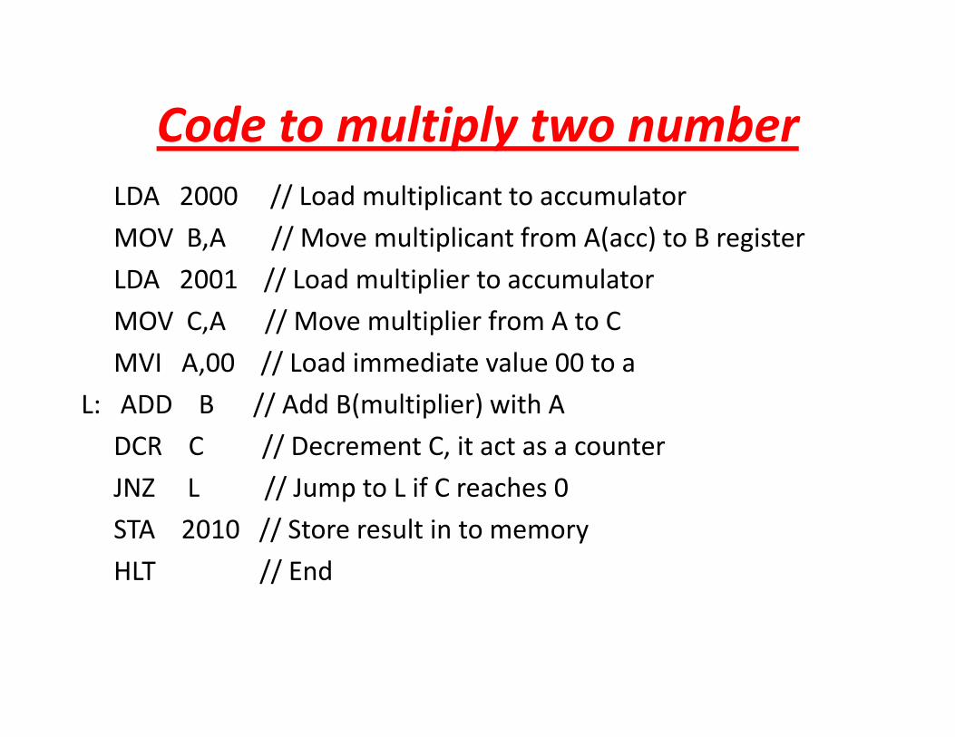
Code to multiply two numberCode to multiply two number LDA 2000 // Load multiplicant to accumulator
MOV B A // M l i li f A( ) B iMOV B,A // Move multiplicant from A(acc) to B register
LDA 2001 // Load multiplier to accumulator
MOV C A // Move multiplier from A to CMOV C,A // Move multiplier from A to C
MVI A,00 // Load immediate value 00 to a
L: ADD B // Add B(multiplier) with A// ( p )
DCR C // Decrement C, it act as a counter
JNZ L // Jump to L if C reaches 0
STA 2010 // Store result in to memory
HLT // End
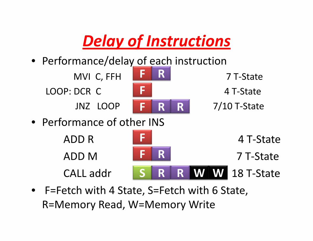
Delay of InstructionsDelay of Instructions • Performance/delay of each instruction
MVI C FFH 7 T StateF RMVI C, FFH 7 T‐State
LOOP: DCR C 4 T‐State
JNZ LOOP 7/10 T State
F RFF R RJNZ LOOP 7/10 T‐State
• Performance of other INS
ADD R 4 T S
F R R
FADD R 4 T‐State
ADD M 7 T‐State
FF R
CALL addr 18 T‐State
• F=Fetch with 4 State, S=Fetch with 6 State,
S R R W W
R=Memory Read, W=Memory Write

Time Delay LoopTime Delay Loop• Performance/delay of each instruction
MVI C FFH 7 T SMVI C, FFH 7 T‐State
LOOP: DCR C 4 T‐StateF RF
JNZ LOOP 7/10 T‐State
• Time delay in loop F R R
TL= T x Loop T‐States x N10
where T=System clock period
N10= Equiv. decimal value of count loaded to C
TL= 0.5x10‐6 x (14 x 255)=1.8ms (ignore 10 T‐State) L ( ) ( g )
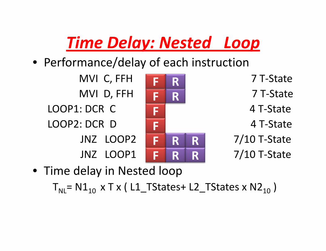
Time Delay: Nested LoopTime Delay: Nested Loop• Performance/delay of each instruction
MVI C FFH 7 T StateF RMVI C, FFH 7 T‐StateMVI D, FFH 7 T‐State
LOOP1: DCR C 4 T‐StateF RF
F R
LOOP1: DCR C 4 T‐StateLOOP2: DCR D 4 T‐State
JNZ LOOP2 7/10 T‐State
F
F R RF
JNZ LOOP2 7/10 T StateJNZ LOOP1 7/10 T‐State
• Time delay in Nested loop
F R RF R R
Time delay in Nested loop TNL= N110 x T x ( L1_TStates+ L2_TStates x N210 )

Traffic Light Control: Counter & DelayLOOP: MVI A 01H
OUT 01HLD B DELAY REDLoad DelayRed
Turn Signal to RedTurn Signal to Red
LD B DELAY_REDCALL DELAY
y
Time DelayTime Delay
Load DelayYellowLoad DelayYellow
Turn Signal to YellowTurn Signal to Yellow MVI A 02HOUT 01HLD B DELAY YELLOW
Time DelayTime Delay
T Si l t G
_CALL DELAY
MVI A 03H
Load DelayGreenLoad DelayGreen
Turn Signal to Green MVI A 03HOUT 01HLD B DELAY_GREENCALL DELAY
Time DelayCALL DELAY
JMP LOOP

Stack Pointer (SP) & Stack Memory( ) y• The stack is an area of memory identified by the programmer for temporary storage ofthe programmer for temporary storage of information.
• The stack is a LIFO structureThe stack is a LIFO structure.• The stack normally grows backwards into memory Memorymemory.– Programmer can defines the bottom of the stack (SP)
Memory
bottom of the stack (SP)and the stack grows up into reducing address range. Bottom
The Stackgrows backwards
of theStack
backwardsinto memory
Stack MemoryStack Memory• Grows backwards into memory
l h b f h k h• Better to place the bottom of the stack at the end of memory
• To keep it as far away from user programs as possible.
• Stack is defined by setting the SP (Stack Pointer) register.) g
LXI SP, FFFFH
• This sets SP to location FFFFH (end of memoryThis sets SP to location FFFFH (end of memory for 8085).

Saving Information on the StackSaving Information on the Stack• Save information by PUSHing onto STACK • Retrieved from STACK by POPing it off• Retrieved from STACK by POPing it off.• PUSH and POP work with register pairs only.E l “PUSH B”• Example “PUSH B”– Decrement SP, Copy B to 0(SP)D SP C C 0(SP)– Decrement SP, Copy C tp 0(SP)
• Example “POP B”( )
B C
F312
– Copy 0(SP) to C, Increment SP– Copy 0(SP) to B, Increment SP
FFFD
FFFC
FFFB
F3
SPFFFF
FFFE 12

Stack/LIFO use in CALL/RET • Retrieve information back into its original location– The order of PUSHs and POPs must be opposite
• 8085 recognizes one additional register pair g g p– PSW (Prog Status word) = ACC and Flag
Before any routine CALL do thisPUSH B
After RETURN from call do this POP PSW
PUSH DPUSH PSW
POP DPOP B

Subroutines• A subroutine is a group of instructions
– That is used repeatedly in different places of theprogram.
– Rather than repeat the same instructions severaltimestimes
– It can be grouped into a subroutine and call from thedifferent locations.
• Instructions for dealing with subroutines.– The CALL instruction is used to redirect program p gexecution to the subroutine.
– The RET instruction is used to return the execution to h llthe calling routine.
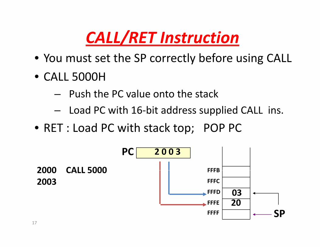
CALL/RET Instruction• You must set the SP correctly before using CALL
• CALL 5000H• CALL 5000H– Push the PC value onto the stack
L d PC ith 16 bit dd li d CALL i– Load PC with 16‐bit address supplied CALL ins.
• RET : Load PC with stack top; POP PC
PC
FFFB
2 0 0 3
2000 CALL 5000
FFFE
FFFD
FFFC
FFFB
0320
2000 CALL 50002003
17
SPFFFF
FFFE 20
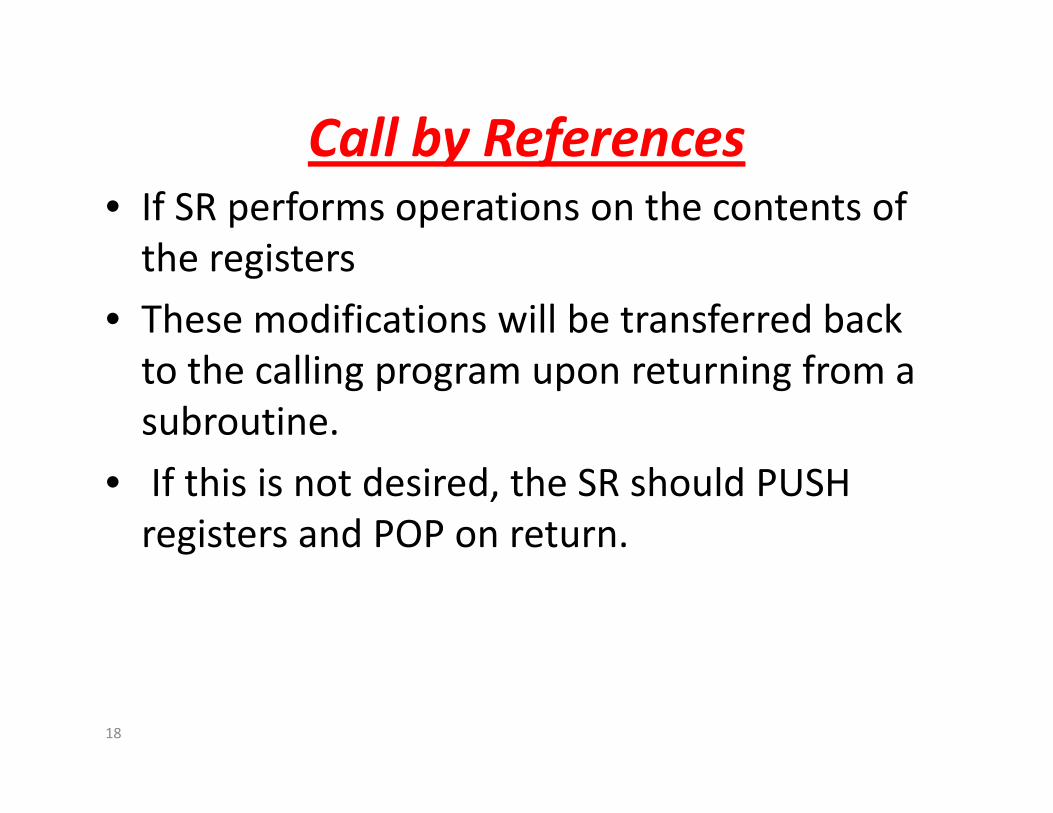
Call by ReferencesCall by References• If SR performs operations on the contents of the registersthe registers
• These modifications will be transferred back h ll fto the calling program upon returning from a
subroutine.
• If this is not desired, the SR should PUSH registers and POP on return.
18

Stack/LIFO use in CALL/RET • Retrieve information back into its original location– The order of PUSHs and POPs must be opposite
• 8085 recognizes one additional register pair g g p– PSW (Prog Status word) = ACC and Flag
Before any routine CALL do thisPUSH B
After RETURN from call do this POP PWD
PUSH DPUSH PSW
POP DPOP B
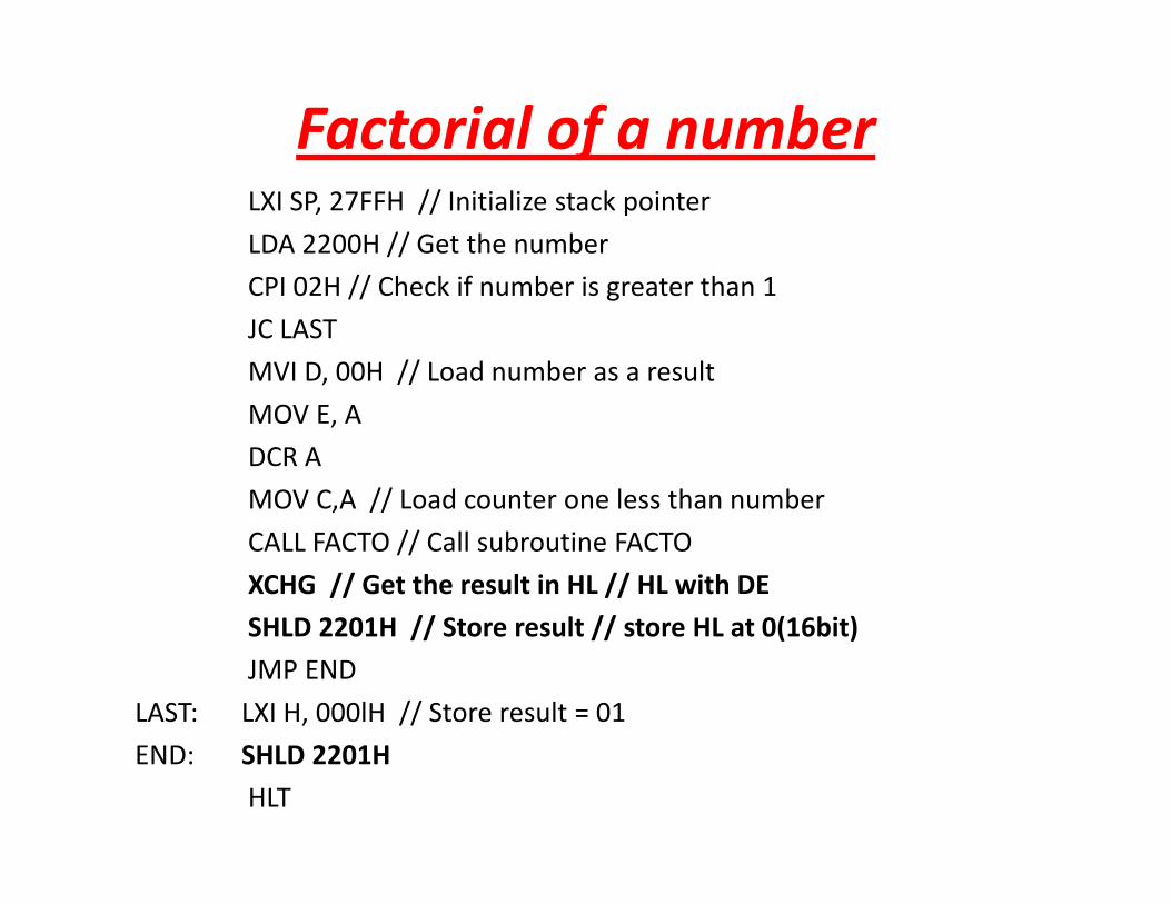
Factorial of a numberLXI SP, 27FFH // Initialize stack pointer
LDA 2200H // Get the number
CPI 02H // Ch k if b i t th 1CPI 02H // Check if number is greater than 1
JC LAST
MVI D, 00H // Load number as a result
MOV E, A
DCR A
MOV C,A // Load counter one less than number, //
CALL FACTO // Call subroutine FACTO
XCHG // Get the result in HL // HL with DE
SHLD 2201H // Store result // store HL at 0(16bit)SHLD 2201H // Store result // store HL at 0(16bit)
JMP END
LAST: LXI H, 000lH // Store result = 01
END: SHLD 2201H
HLT

Sub Routine for FACTORIALSub Routine for FACTORIAL
FACTO:LXI H, 0000H
MOV B, C // Load counter
BACK: DAD D // double add ; HL=HL+DE
DCR BDCR B
JNZ BACK //Multiply by successive addition
XCHG // Store result in DE // HL with DE
C C //DCR C // Decrement counter
CNZ FACTO // Call subroutine FACTO
RET // Return to main program

Assignment I • Write and execute 8085 assembly language program to find value of Nth Fibonacci number (R i i i i b ti(Recursive version: using recursive subroutine call)
• 16 bit can support up to 65356 > F• 16 bit can support up to 65356 > F24
• Deadline 12th Aug 2010 11 55Mid night• Deadline: 12th Aug 2010, 11.55Mid night• After deadline grading: Max 5 out of 10 S d TXT i f ith fil• Send TXT version of program with file name RollNo.txt to [email protected] with Assignment one as subject of emailAssignment one as subject of email
• Don’t submit copied one: will get Negative marks

Introduction to 8086 & i386 processor
• 16 bit Microprocessor16 bit Microprocessor
• All internal registers as well as internal and external data buses were 16 bits wideexternal data buses were 16 bits wide
• 4 Main Register, 4 Index Register, 4 Segment R i S R I PRegister, Status Reg, Instr Ptr.
• Not compatible with 8085, but with successors
• Two Unit works in parallel:– Bus Interface Unit (BIU)( )
– Execution Unit (EI)

8086 ArchitectureBus Interface
Unit C BUS
Q6Q6Q5Q5Q4Q4Q3Q3Q2Q2Q1Q1
SUM
CS (Code Seg Reg)CS (Code Seg Reg)DS (Data Seg Reg )DS (Data Seg Reg )ES (Extra Seg Reg )ES (Extra Seg Reg )SS (Stack Seg Reg)SS (Stack Seg Reg)
IP (Intr Ptr) Sequencer( )IP (Intr Ptr)OperandOperandInDirectInDirect
SequencerExecution
Unit A BUS
AHAH ALALBHBH BLBLCHCH CLCLDHDH DLDL
SI (Source Idx )SI (Source Idx )DI (Dest Idx)
Temp ATemp ATemp B Temp B Temp CTemp C
( )DI (Dest. Idx)BP (Base Ptr )BP (Base Ptr )SP (Stack Ptr)SP (Stack Ptr)
Z (Flag Reg)
ALU

8086 Registers8086 Registers
• AX ‐ the accumulator register (divided into AH / AL) AH AL• BX ‐ the base address register (divided into BH / BL)
• CX ‐ the count register (divided into CH / CL)
• DX ‐ the data register (divided into DH / DL)
BHBH BLBLCHCH CLCLDHDH DLDL
DX the data register (divided into DH / DL)
• SI ‐ source index register.
d i i i d i
SI (Source Idx )DI (Dest. Idx)DI (Dest. Idx)BP (Base Ptr )BP (Base Ptr )SP (St k Pt )• DI ‐ destination index register.
• BP ‐ base pointer.
• SP ‐ stack pointer.
SP (Stack Ptr)
CS (Code Seg Reg)
Z (Flag Reg)
CS (Code Seg Reg)DS (Data Seg Reg )DS (Data Seg Reg )ES (Extra Seg Reg )ES (Extra Seg Reg )SS (Stack Seg Reg)SS (Stack Seg Reg)
IP (Intr Ptr)IP (Intr Ptr)

8086 Architecture• Execution Unit :
– ALU may be loaded from three temp registers (TMPA, TMPB, TMPC)
– Execute operations on bytes or 16‐bit words. – The result stored into temp reg or registers connected to the
internal data bus. • Bus Interface Unit
– BIU is intended to compute the addresses.– Two temporary registers p y g– indirect addressing– four segment registers (DS, CS, SS and ES), – Program counter (IP ‐ Instruction Pointer), g ( ),– A 6‐byte Queue Buffer to store the pre‐fetched opcodes and data.– This Prefetch Queue optimize the bus usage. – To execute a jump instruction the queue has to be flushed since theTo execute a jump instruction the queue has to be flushed since the
pre‐fetched instructions do not have to be executed.

Next Class AgendaNext Class Agenda• Detail of 8086 Architecture
• Advanced 32 bit architecture (i386, Pentium, p4)– I know a little bit of this
– My expertise area of work
• Programming model for x86 architectureProgramming model for x86 architecture
• 8086 Assembly language programming
• MASM / TASM /NASM ( 86 assembler)• MASM / TASM /NASM (x86 assembler)
• If you miss the next class, will miss a lot

Th kThanks