RIEPORT NO. 00O - TSC - FAA- 71'- 14
. iEAL-THE SIMULATION PROGRAM FOR
SWE lAV" LAND (CANADA)'"'BUFFALO"lN I•N " .T1IN OTTER'" SI0 TRANSPORTS
R. A. MacDON ..0, MEL GARELICK, J, HAAS
TRANSPORTATV - SYSTEMS CENTER,
55 BROADWAYCAMBRIDGE, M'SS. 02142
TECHNICAL N HOE
Availability is unlicte~d., Oewfsna ' b RteeTo th National Tednical |nfonsetim $er1ic.Springfield, Vlrginl 22151, for Sol* to ,b Pgi~l€.
Prepared for B
"DEPARTMEN1 OF TRANSPORTATIONFEDERAL AVIATION ADMINISTRATIONWASHINGTON. D.C. 20590
Repropluc-l by
NATIONAL TECHNICALINFORMATION SERVICE
U S De0 ortmet of CommrqrceSangftjld VA 22151
The conter.7s of this report reflect the viewsof the Tranlsportation Systems Center which Isresponsibl l: for the facts and the accuracyof the data: presented herein.' The contentsdo not nec•issarily reflect the official viewsor policy of the Department of Transportation.This report does not constitute a standard,specification or regulation.
11 $WMCLT0w I IIC O ...............
213T. AVAIL all/If WW"
i b

1. Report No. 2 Government Accession No. 3. Recipient's Cat-log No.DOT-TSC-FAA-71-14_
4. Title and Subtitle 5. Report Date
REAL-TIME SIMULATION PROGRAM FOR J-Tune "25. 1971DE HAVILLAND (CANADA) "BUFFALO" AND 6. Performing Organization Code
"TWTN )T'TPR" STOT. TRANqDPORT7 Author(',Perlo, ý: k ,,gAC DONALD*, MEL GARELICKk8. Performing Organization Report No.
9 Pe ifo,.tng Organization Name and Address 10. Work Unit No.
Department of Transportation 11. ContractorGrantNo.
Transportation Systems CenterEA-] 8
55 Broadway, Cambridge, Mass. 02142 13. Type of Report and Period Covered
I2 Sponsoring Agency Home and Address
Department of Transportation Technical NoteFederal Aviation AdministrationWashington, D.C. 20590 14. Sponsoring Agency Code
15 Supplementary Notes
*Service Technology CorporationCambridge, Ma. 02142
16 Abstract Simulation models of two representative STOLaircraft - the DeHavilland (Canada) "Buffalo" and "TwinOtter" transports - have been generated.
The aircraft are described by means of non-linear equations that will accommodate gross changes inangle of attack, pitch angle, flight path angle, velocityand power setting. Aircraft motions in response tocontrol inputs and external disturbances are related toEarth-fixed coordinates. The equations are programmed torun in "real time" so that they can be used in con-junction with a manned cockpit simulator. Provisions aremade for pilot control inputs to the simulation, andconventional panel display parameters are generated.
The report includes representative simulationresults which demonstrate that the simulation is anadequate representation of the two STOL aircraft beingmodeled.
17. KeyWords Aircraft Math Model 418. Distribution Statement
STOL Aircraft Stability and Availability is Unlimited. Document miy be ReleasedTo the National Technical Information Service,Control ; Aircraft Simulatio1 Springfield, Virginia 22151, for Sale to the Public.
19 Sscu.twy Clossif. (of this report) 20 Security Clossif. (of this page) 21. No. of Pages 22. Price
Unclassific Unclassified 57 ,.'
TABLE OF CONTENTS
Page
List of Symbols ............... ........................ i
I. Introduction ............................. 1
II. Description of .1athematical Model. . . . ......... . . 3A. Definition )f Reference Coordinate FramesB. Velocity * -solutionsC. Provision- for Atmospheric Disturbances (Winds)D. Airframe 2-uations of MotionE. Definiti-, of Required Display Quantities
III. Tabulation of Numerical Data for "Buffalo" and "Twin Otter". 18IV. Simulation ! ,:ogram . .. . .. .. .. .. .... .. .. ... 21
A. Interfarie with GAT-l CockpitB. Defini'4jon of Initial Values of Variables
V. Simulation Results . . . . . . . . . . . ............ 24References . .......................... . 26Table I . . . . . . . . . . . . . . . . . . . . . . . . . . . . 27Figures ............... . ................... 35Appendic ..................................... Al
ell:
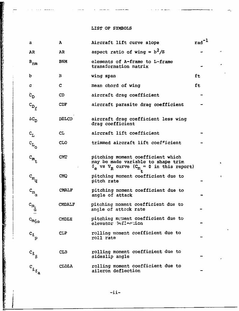
LIST OF SYMBOLS
a A Aircraft lift curve slope rad- 1
AR AR aspect ratio of wing = b 2 /S
B nm BNM elements of A-frame to L-frametransformation matrix
b B wing span ft
c C mean chord of wing ft
CD CD aircraft drag coefficient
CDf CDF aircraft parasite drag coefficient
ACD DELCD aircraft drag coefficient less wingdrag coefficient
CL CL aircraft lift coefficient
CL CLO trimmed aircraft lift coe:Vicient0
Cm CMT pitching moment coefficient whicht may be made variable to shape trim
6 e vs VR curve (Cm = 0 in this report)
Cm CMQ pitching moment coefficient due toq pitch rate
Cm CMALF pitching moment coefficient due toa angle of attack
Cm CMDALF pitching moment coefficient due to& angle of attack rate
C- CMDLE pitching mc:iient coefficient due toe elevator "]I ai"ion
CA CLP rolling moment coefficient due toP roll rate
CA CLB rolling moment coefficient due tosideslip angle
C CLDLA rolling moment coefficient due toPsa aileron deflection
-ii-

r CLR rolling moment coefficient due to
yaw rate
C CLRFIN fin contribution to rollingr moment coefficient due to yawfin rate
Cn CNP yawing moment coefficient duep to roll rate
Cn CNPFIN fin contribution to yawingp. moment coefficient due to yaw
Pfin rate
C CNR yawing moment coefficient due tonr yaw rate
Cn CNRFIN fin contribution to yawing momentrfin coefficient due to yaw rate
C CNB yawing moment coefficient due tosideslip angle
I4rI CNDLR yawing moment coefficient due torudder deflection
Cy CYP side force coefficient due toyp roll rate
C y CYR side force coefficient due to~r yaw rate
C CYB side force coefficient due tosideslip angle
CT CTl empirical coefficient in thrust1 equation fps-1
CTC.22 empirical coefficient in thrust2 equation fps 2
D DRAG aircraft drag lbs
e E aircraft efficiency factor(2
g G gravitional constant = 32.2 ft/sec2
h H altitude =-z ftL
h HATM characteristic density altitude ofATM atmosphere ft
-iii-
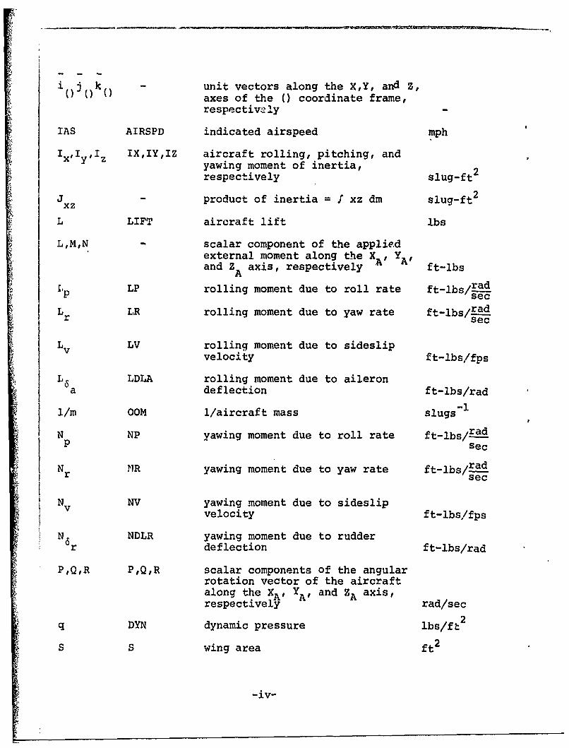
i(j(() k unit vectors along the X,Y, and Z,axes of the () coordinate frame,respective>ly
IAS AIRSPD indicated airspeed mph
IxI YIz IXIYIZ aircraft rolling, pitching, andyawing moment of inertia,respectively slug-ft
J - product of inertia = I xz dm slug-ft 2
xz
L LIFT aircraft lift lbs
L,M,N - scalar component of the appliedexternal moment along the XA, YA'and ZA axis, respectively ft-lbs
LP rolling moment due to roll rate ft-lbs/a-Lp sec
L LR rolling moment due to yaw rate ft-lbs/radr sec
Lv LV rolling moment due to sideslipvelocity ft-lbs/fps
j L LDLA rolling moment due to aileron5a deflection ft-lbs/rad
1i/m OOM 1/aircraft mass slugs- 1
N NP yawing moment due to roll rate ft-lbs/-P Sec
Nr NR yawing moment due to yaw rate ft-lbs/radsec
Nv NV yawing moment due to sideslipvelocity ft-lbs/fps
N r NDLR yawing moment due to rudderdeflection ft-lbs/rad
P,Q,R P,Q,R scalar components of the angularrotation vector of the aircraftalong the XA, YA' and ZA axis,respectively rad/sec
q DYN dynamic pressure lbs/ft2
S S wing area ft 2
-iv-
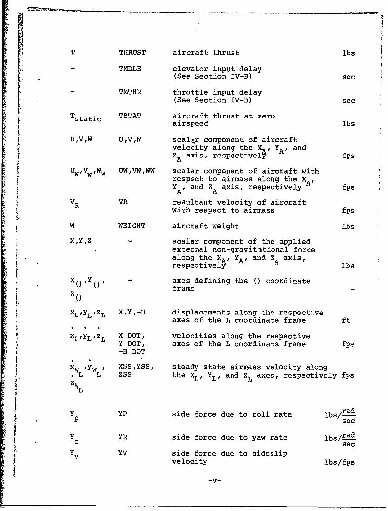
3IT THRUST aircraft thrust lbs
- TMDLE elevator input delay(See Section IV-B) sec
TMTHR throttle input delay•+(See Section IV-B) sec
Tstatic TSTAT aircraft thrust at zeroairspeed Sbs
tJ,V,W UVW scalar component of aircraftvelocity along the XA' YA' andZA axis, respectively fps
UwVwWw UW,VW,WW scalar component of aircraft withrespect to airmass along the XA,Y , and Z axis, respectively fpsA A
VR VR resultant velocity of aircraftwith respect to airmass fps
W WEIGHT aircraft weight lbs
X,Y,Z - scalar component of the appliedexternal non-gravitttional forcealong the XA, YA' and Z axis,respectively A lbs
"" 0) Y - axes defining the () coordinate
frameZ ()
XLyLzL X,Y,-H displacements along the respectiveS7 axes of the L coordinate frame ft
x X DOT, velocities along the respectiveY DOT, axes of the L coordinate frame fps-H DOT
x Yw ' XSSYSS, steady state airmass velocity along. L L ZSS the XL, YL' and ZL axes, respectively fps
Y YP side force due to roll rate lbs/rad
Y YR side force due to yaw rate lbs/radr sec
Y YV side force due to sideslipvelocity lbs/fps
~-V--

SALF angle from the remote windvector V to the X axib i ad
R A r.
DALF da/dt . ad/see
a angle from the remote wind,B vector VR to the XB axis ra,
aBALFBO angle between the body-fixed0 ~ XA and X B axes " rad
a AFBOL value of a for which no liftBoL is developed by the air~raft, rad
SBETA aircraft sideslip angle rad
Y angle from the horizontalreference line to the iemote.wind vector VR: Y = 0 -a, rad
6 DLA aileron deflection rada
6 DLE elevator deflection ta-d
6r DLR rudder deflect *ion tad
E) THETA (See definition of Euler anglesT,o,ý below)
• 0B angle from the horizontal refekenceB line to the X B axis rad
S•THROT pilot throttle input as fractionof maximum input : -
S p RHO atmaospheric air density slugs/ft3
Po RtHOSEA atmospheric air density at,sea level, std day sl ,ugs/ft3
,i.,a SIG P/Po
- ,E),ý PSI, THETA Euler angles relating L, C, and APHI coordinate frames (further defined
in Figure 3) ,,ad
I ~~-vi- ,

SUBSCRIPTS
A aircraft body roordinate frame
B body reference poordinate frame
C Earth-aircraft cont.ol coordinate frame
L '. Earth local-vertica1, coordinate frame
cr design economy1 cruise condition
OL zero lift value
v'I I
ii
I -vii
[• I Introduction
Simulation models of two representative STOL aircraft
have been generated. The models are documented in this
report.
The computer simulation is to be used as a tool in the
development of STOL terminal area guidance and navigation
systems.
This intended use has determined the form of the simulation:
The aircraft are described by means of non-linear equations that
will accomodate gross changes in angle of attack, pitch angle,.
4 •flight path angle, velocity, and power setting. Aircraft motioas
iii response to control inputs and external disturbances are
related to Earth-fixed coordinates. The equations are programmed
to run in "real time" so that they can be used in conjunction
with a manned cockpit simulator. Provisions are made for pilot
control inputs to the simulation, and conventional panel display
parameters are generated.
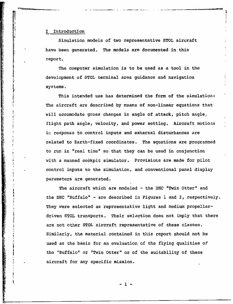
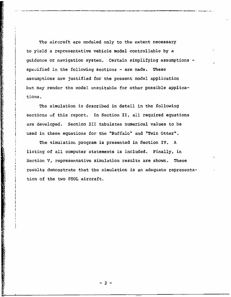
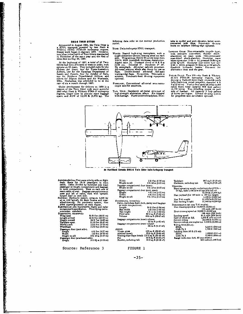
The aircraft which are modeled - the DHC "Twin Otter" and
the DHC "Buffalo" - are described in Figures 1 and 2, respectively.
They were selected as representative light and medium propeller-
driven STOL transports. Their selection does not imply that there
are not other STOL aircraft representative of these classes.
Similarly, the material contained in this report should not be
used as the basis for an evaluation of the flying qualities of
the "Buffalo" or "Twin Otter" or of the suitability of these
aircraft for any specific mission.
It • [ -1 -
The aircraft are modeled only to the extent necessary
to yield a representative vehicle model controllable by a
guidance or navigation system. Certain simplifying assumptions -
specified in the following sections - are made. These
assumptions are justified for the present model application
but may render the model unsuitable for other possible applica-
tions.
The simulation is described in detail in the following
sections uf this report. In Section II, all required equations
are developed. Section III tabulates numerical values to be
used in these equations for the "Buffalo" and "Twin Otter".
The simulation program is presented in Section IV. A
listing of all computer statements is included. Finally, in
Section V, representative simulation results are shown. These
results demonstrate that the simulation is an adequate representa-
tion of the two STOL aircraft.
-2-
II Description of Mathematical Model
The mathematical model consists of all equations required
to describe the motions of the aircraft in space resulting
Lrom external disturbances, control inputs, and the aircraft's
aerodynamic characteristics. These equations are presented
in this Section. First, however, it is necessary to define
the reference coordinate frames to be used.
IIA Definition of Reference Coordinate Frames
Reference coordinate frames to be used in this analysis are
defined in this section. Insofar as possible, axis systems have
been defined so that senses of rotation and translation are
similar for small rotations. Positive force, moment, and motion
vector components are defined to be in the positive sense of
the axis. To the largest extent possible, the symbols and
conventions used are consistent with those in commcn usage in
the guidance and control fields and with those used by NASA for
aircraft stability and control work.
The Earth Local-Vertical Frame (L) is a local geographic
frame. Its origin is fixed at a point on the Earth's surface with
ZL along the vertical defined by the local gravity vector
(positive downward), XL parallel to geographic North (positive
to the North), and YL parallel to geographic East (positive
to the East).
The Aircraft Body Coordinate Frame (A) is fixed to the
aircraft and r--1 es and translates with the aircraft. Its
origin is the center of mass of the aircraft. The XA axis
is chosen in a forward direction in the plane of symmetry that
-3-

is parallel to the initial or equilibrium direction of the
remote wind. Thus the A-frame axes, by the commonly accepted
definition, are "stability axes". Because hhe XA axis is
initially aligned with the remote wind, the initial angle of
attack a(o) = a is zero. (In this report, 0 and a when not
subscripted to indicate reference frame, are assumed to be
referenced to the A-frame. Further, since in the simulation
documented in this report the aircraft is placed in equilibrium
at t = 0, "equilibrium" and "initia'" conditions are equivalent.)
The Y axis is normal to the aircraft's plane of symmetryA
(positive to the right), and the ZA axis is in the plane of
symmetry (positive downward) and orthogonal to the XA and YAA A
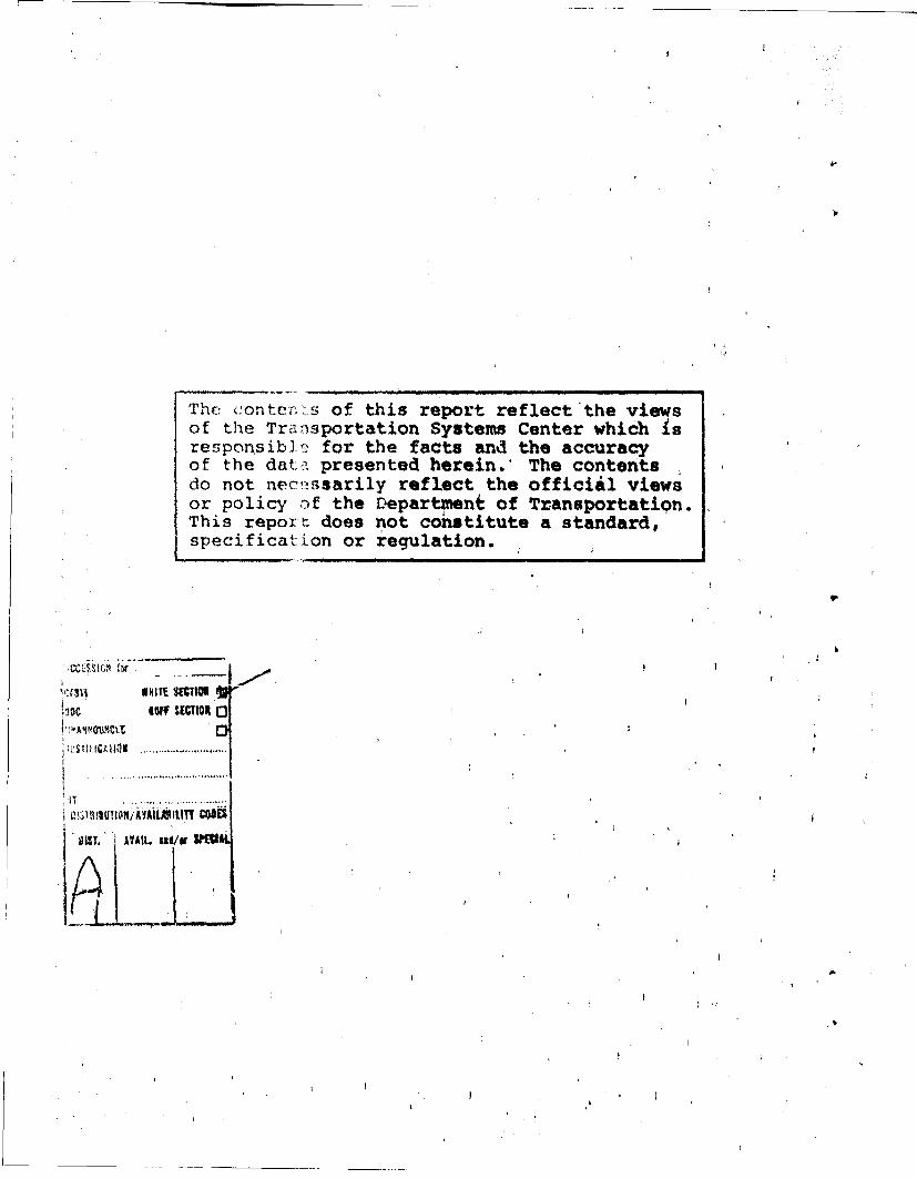
axes. The A-frame is related to the L-frame (and to the next-
defined C-frame) in Figure 3.
The Earth-Aircraft Control Coordinate Frame (C) is also
centered at the center of mass of the aircraft. The ZC axis
is aligned with the local gravity vector (positive downward)
and is therefore parallel to the ZL axis. The X axis isL C
the intersection of the horizontal plane with the vertical
plane containing the X axis. The YC axis completes theA
orthogonal right-hand system. The C-frame is an intermediate
frame needed to define the Euler angles describing the relation-
ship between the Earth local-vertical (L) frame and the Aircraft
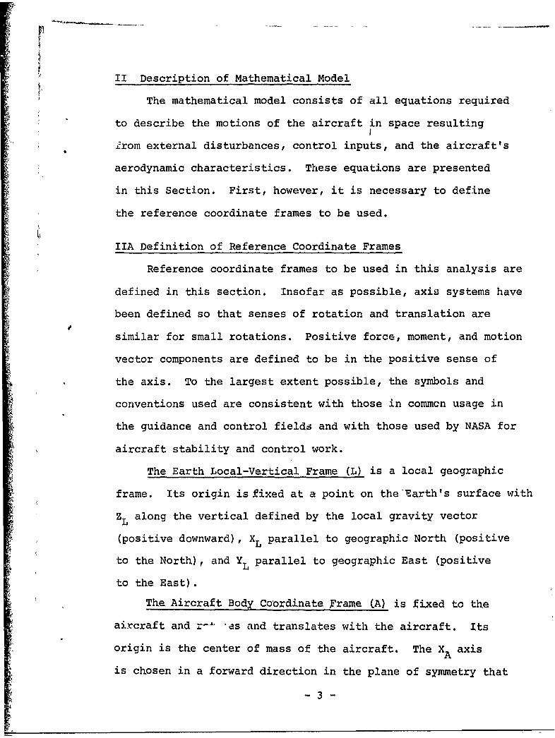
body (A) frame. In their order of rotation (which must be
preserved) the Euler angles are defined as:
- 4 -
1. Heading (T): angle of rotation about Zfrom X to XC; 'j.L '
2. Pitch (0)1: angle of•'rotation about Yfrom X to X;'
AS3,. Roll (M): angle of rotation about X
from Y to YC A
These Euler angle rotations are shown in Figure 3.
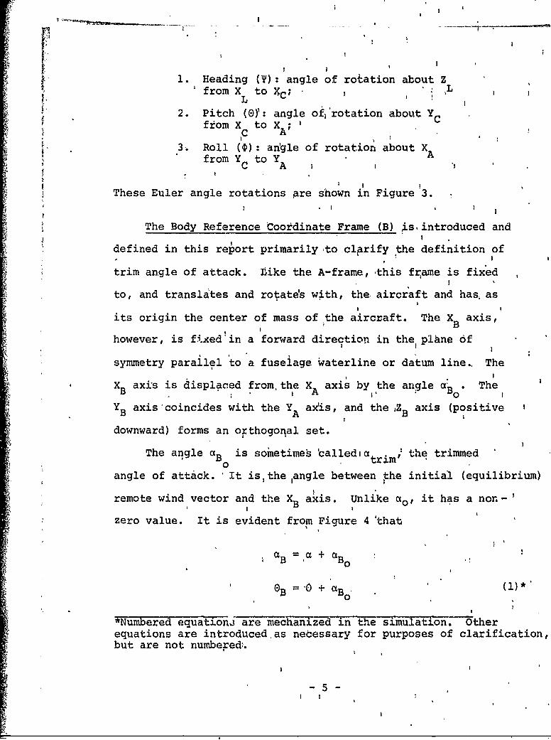
The Body Reference Coordinate Frame (B) .s, introduced and
defined in this report primarilyto clprify the definition of
trim angle of attack. tike the A-frame, this frame is fixed
to, and translates and rotates with, the aircraft and has, as
its origin the center of mass of the aircraft. The XB axis,
however, is fixed'in a forward direction in the plhne of
symmetry parallel to a fuseiage wqaterline or datum line., TheXB axis is displaced from, the X axis by the angle ae . The
B A v oYB axis'coincides with the Y axfis, and the ,Z axis (positive
BA Bdownward) forms an orthogoqal set.
The angle aB is sometime's alledia the trimmedangle of attack. 'It isthe ,angle between rhe initial (equilibrium)
remote wind vector and the XB axis. Unlike ao, it has a non-'
zero value. It is evident from Figure 4 'that
I ~B I0}•B = BO :
OB '0 + ' (11*0
*Numbered equationj are mechanizid in the simulation. Otherequations are introduced as necessary for purposes of clarification,but are not numbered.
I I

and, for equilibrium level flight, that
B a:B B20 o
The trim angle •Bo can be approximated in the following
fashion in the absence of wind tunnel or flight.,test:datai
Assumihg a' constant 9 .raft lift 6urve slope, a,:skdtch
the aircraft's lift curve:
,CL
* slopoa
(XI30
)L
I'rom the sketch it'is apparent that
C a
or, at equiJ~ibrium,
CL a (aB ao)L B L'OL
Next, assume that wing incidence has been chosen by the aircraft
manufacturer to produce a level fuselage attitude ý(aB 0) when,I 0
,the aDrcraftlis in flight at "Economy Cruise Speed" at 10000 ft
and at an arbitrarily -'chosen average gross weight., Usingthe
CL coefficiento -•BO)
relation Wcr S, wirg calculate theas lift coetat the, reltion cr .CLcr qcrscauatthli, ofientte
' flight condition. The -: le of'attack for zero lift c~n then
be calculated from the ibove equation as• 2CLcr
, B = - I-aOL
* -6-
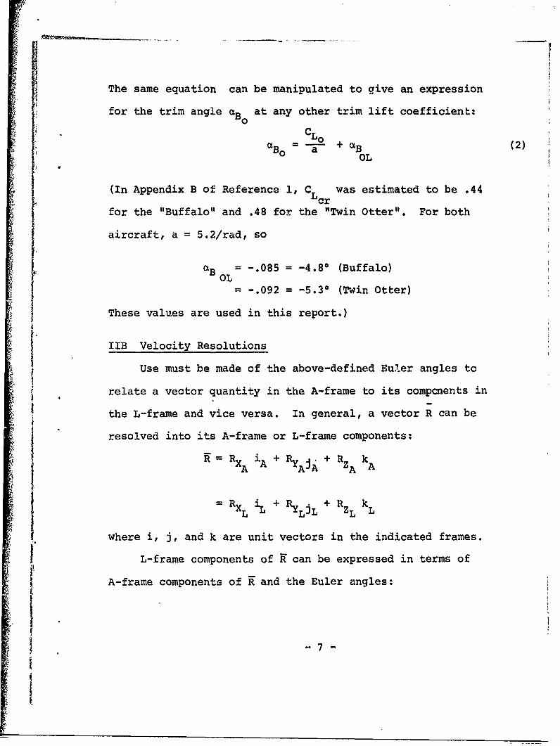
The same equation can be manipulated to give an expression
for the trim angle Ba at any other trim lift coefficient:
CLa = + (2)B0 a +a
OL
(In Appendix B of Reference 1, C was estimated to be .44Lcr
for the "Buffalo" and .48 for the "Twin Otter". For both
aircraft, a = 5.2/rad, so
aB = -. 085 = -4.8* (Buffalo)
OL= -. 092 = -5.30 (Twin Otter)
These values are used in this report.)
IIB Velocity Resolutions
Use must be made of the above-defined Euler angles to
relate a vector quantity in the A-frame to its compcnents in
the L-frame and vice versa. In general, a vector R can be
resolved into its A-frame or L-frame components:
R XA i A + RYAJA + kA
RXL iL Ry LiL +RZL kL
where i, j, and k are unit vectors in the indicated frames.
L-frame components of K can be expressed in terms of
A-frame components of R and the Euler angles:
-7-
[1

R BII BI2 B 1.RXXL'1-1 13 A'
R B B B RY L 21 22 23 ..L
R Z B 31 B B RZ 1 32 B33 Z-
L AjLJ
where BII =cos T cos 0 (3)
BI2 cos T sin 0 sin P - sin T cos 0 (4)
B =cos T sin 0 cos 0 + sin T sin 0 (5)
13
B =sin T cos 0 (6)21
B =sin T sin 0 sin 0 + cos T cos 10 (7)22
B23 =sin T sin ocos$-cos T sin 0 (8)
B31 -sin 0 (9)
B =cos 0 sin 0 (10)32
B = cos 0 cos 0 (11)33
Conversely, A-frame components of any vector • can be expressed
in terms of L-frame components:
R B B B RX 11 21 31 XL
R B B B 3-Y A 12 22 32
R A B 13 23 33 R zL
-8-

Thus, in the simulation, the A-frame components of aircraft
velocity (XA EU, ýA = V, and 2A = W) are computed and used
to obtain velocity components with respect to the ground:.
S=B U + B V + B W (fps) (12)L 11 12 13
Y= B U + B V + B W (fps) (13)L 21 22 23
-Z =-B U -B V - B W (fps) (14)
L 31 32 33
IIC Provisions for Atmospheric Disturbances (Winds)
Winds are input into the simulation in the L-frame.
Components are *w (positive North), Y (positive East),L L
and ýw (positive downward). The winds are resolved intoL
A-frame components in equations 15-17 in order to compute
airspeed components:
U w U - [Bl wL + B2 1 YwL + B3 1 z] (fps) (15)
V = V - [B 12 + B2 2 w + B32 z WL (fps) (16)w 12wL L 3 1
Ww = W - [BI3 kWL + B23 wL + B33 ZL (fps) (17)
Material contained in this report is sufficient to allow
introduction of steady state wind components. The desired
winds are simply input as x YW,, ,and z W The report does
not document wind gust or wind shear models. However, these
models, when developed, can be readily incorporated into the
simulation with only minor modifications to the program being
required.
-9-

IID Airframe Equations of Motion
In Reference 1, general 6 degree of freedom airframe
equations of motion were developed as
m [U + QW - RV + g sin 0] = X (longitudinal force)
m [V+ RU - PW - g cos 0 sin f]= Y (side force)
m [W+ PV - QU - g cos Cos D]= Z (normal force)
I P + (I - I ) QR - J (R + PQ) =L (rolling moment)
Iy + 1 I) - Jxz (R2 P2 ) =M (pitching moment)
I R + (Iy - Ix) PQ -J ( - QR)= N (yawing moment)
where the body-axis angular rates P, Q, and R, can be used to
obtain Euler angle rates according to the equations
oQ sin__+ R cos _ (rad/sec) (18)cos E) Cos 0
=Q cos t - R sin 5 (rad/sec) (19)
S= P + ' sin 0 (rad/sec) (20)
These nine equations, together with equations 12-14, provide an
almost exact description of the motions of an aircraft operating
near the Earth's surface. They in-volve, as shown in Reference 1,
only four assumptions:
1. Aircraft mass is constant
2. The Earth can be considered an inertial frame
3. The aircraft is a rigid body
4. The aircraft is symmetrical about itsx - z plane.
1
I - 10 -
. - - -

For purposes of this simulation, the above 6 rigid body
airframe equations have been approximated as
* 2U=RV - QW - g sin 0 + X/m (ft/sec2) (21)
=PW - RU + g cos 0 sin 0 + Y/m (ft/sec2) (22)
QU - PV + g cos 0 cos 0 + Z/m (ft/sec) (23)
P= L/I (rad/sec 2) (24)
M=/I (rad/sec 2) (25)Y 2
R= N/I (rad/sec ) (26)
The omitted terms in the moment equations involve either products
of angular velocities (e.g. QR) felt to be small compared with
other equation terms, or terms containing J which will be
neglected. Experience has shown that, for purposes of this
simulation, these terms can be omitted with negligible effect
on results.
The terms X, Y, Z, L, M, and N of equations 21 - 26 represent
the aerodynamic forces and moments acting on the aircraft. The
lateral terms (Y, L, N) will be expressed in a quasi-linear form
(as in Reference 1), but the longitudinal forces and moment (X,Z,M)
must be non-linear in order to permit large excursions in forward
velocity.
The longitudinal aerodynamic force terms are, from the sketch,
X = T - D cos a + L sin a (ibs) (27)
Z = - (Lcos a + D sin a) (ibs) (28)
I; ~- 11-

L
Az
The terms Xq, Zq, Z•, and Z6have been neglected in thisX e
IT
analysis because of their small contribution to the overall
forces.
It is also assumed that all thrust forces act along the XA
axis. Thus moment effects of thrust changes are neglected, as are
forces and moments produced by special lift devices operating
within or outside of the propeller slipstream. These effects
are neglected because the airframe data required to model them
are not available.
Equations 27 and 28 are solved (as are the other simulation
equations) once every computer iteration cycle. Thrust, drag,
and lift force components are summed to produce resultant X and
Z forces acting on the aircraft.
Expressions for the total thrust, lift, and drag forces
are next developed.
Thrust is computed from an empirically-derived expression
(developed in the appendix) which accounts for the effects of
altitude h, airspeed VR, and throttle setting •:
- 12 -

aT staticT = V 2 •(1bs) (29)'1 +CT VR + C V
l+T R 1T R
where 0 - _ 1.0,
a =eh/hatm, ( .(30)
and
VR = [Uw2 + V 2 + W2]1 /2 (fps) (31i
Lift and drag are calculated from the 'standard relationships:
L = CL qS (lbs) (32)
D = CD qS * (lbs) (33)
where
CL = CL + aa (-) H (34)0
CD = CD + C /reAR(-) H (35)f
1 2 (lbs/ft 2) (36)1
p = a p0 (sl/ft3 (37)i
4 and
a = tan- Ww/Uw (rad) (38)
The expression for pitching mop-it i-ed in the simulation
is
cM =qSc[Cmt + Cm a + (Cm. + ++ Cm 6e M (39)aR a q
where the coefficients of the variables are constants. The
term Cm is zero in this report, but is included to facilitatet
-13-

I I
later shaping ..f the trimmed ýe vs V curve. To do this, CmRt
would be Made a function of VR
Rate of change with time of angle of attack is obtained by
idifferentiating pquation 38:
Wi(tan -
Sdf U w
U W -w ua Ww w w
If the approximation is, made that U U 'and W Ww' the aboveI w
'expression can be manipulated to prbduceS12
U- w o) (rad/sec) (40)wU U
which is the expression used'in the'simulation.
The lateial force (Y) and moments (L and N) areI l
developed in conventional linearized form (as in Reference 1)
except that total mariables are used rather than perturbation
values, and that coefficients of the lateral variables are made
,functions of liftland drag coefficient, airspqed, and dynamic
pressure, all of which are determined by solution of the
longitudinal equaeions.
:The lateral force and moment expressions used in the
simulation are:
Y= Y V i+ Y Pvr (ibs) (41)
L'= LV ýw + Lr R +'Lp P + L6a' 6a (ft-lbs) (42)
N =N Vw + Nr R + Np P.+ N6r 6 (ft-lbs) (43)v. wrr14
II - 14 -
: I.

The terms Y6 , L6, and N6 , sometimes included in the lateralr r a
equations, have been omitted in the present analysis because of
their negligible effects.
The coefficients of these equations are
YV VR S C (lbs/fps) (44)
Y =- V Sb C (ibs/rad) (45)r 4 R Yr sec
1iYp =-p VR Sb Cy (ibs/r-)se (46)
LV= •P VR Sb CP, (ft-lbs/fps) (47)
L Sb C (ft-lbs/-) (48)r 4 R r. secR £r
Cz r CkF + CL/ 4 ( (49)Sr rFiN
1 2 radL = p V Sb Ce (ft-lbS/s-ec) (50)
p 4 R p
L = q Sb C,6 (ft-lbs/rad) (51)a a
Nv = 1P VR Sb Cn (ft-lbs/fps) (52)
12 radN 4- p V Sb C (ft-lbs/-) (53)r 4 R nr sec
Cn Cn -Cd /4 (-) (54)rn r wingr rFIN
1 2irad-- PV Sb2 Cn(t- (55)p 4 R npsec
C CL (56Cn = cn - - -• (-) (56)
np n4 7TAR"" P PFIN
Nr = q Sb Cn (ft-lbs/rad) (57)r
5- 1 -
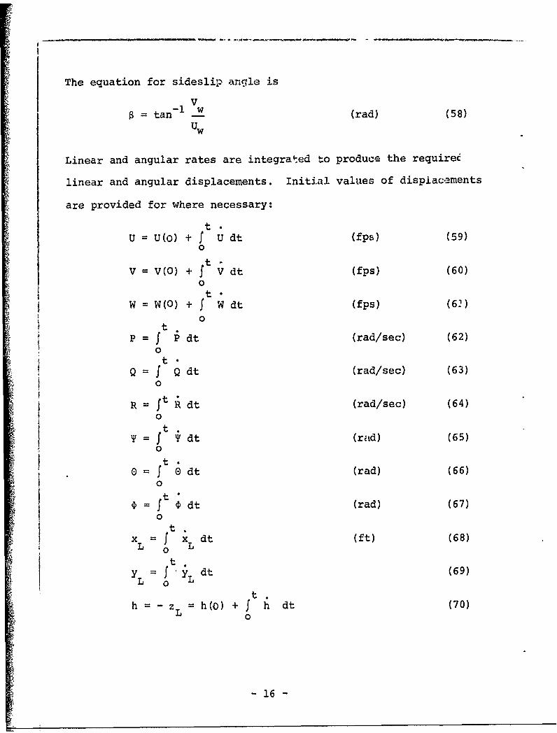
The equation for sideslip angle is
V0 = tan- - (rad) (58)
UW
Linear and angular rates are integrated to produce the requiree
linear and angular displacements. Initial values of displacements
are provided for where necessary:
t •U = U(O) + f U dt (fps) (59)
0
V=V(O) +f Vdt (fps) (60)
0t•
W = W(O) + f W dt (fps) (62)0
tP = f P dt (rad/sec) (62)
ot
Q = f Q dt (rad/sec) (63)0
R = t Rdt (rad/sec) (64)
0T = ft dt (rad) (65)
0
0 =f dt (rad) (66)
0
t.
x = f x dt (ft) (67)L o L
t
t ty' f dt (69)
h = - zL = h(O) + f h dt (70)0
- 16 -

4
HIE Definition of Required Display Quantities
Provisions are made in the simulation for displaying
parameters that are commonly available on a cockpit instrument
panel. These parameters are tabulated here (and are defined if
they have not been previously defined):1i/2
Indicated Airspeed IAS - V (mph)
Altimeter Output h (ft)
Directional Gyro Output 57.3 Y (deg)
Pitch Attitude Gyro Output 57.3 0B (deg)
Roll Attitude Gyro Output 57.3 0 (deg)
Rate of Climb Indicator Output fi/60 (fpm)
Turn Rate Indicator Output 57.3 R (deg/sec)
Slip Indicator Output
[g cos sin - V - RU + PW] (rad)g cos 0 cos P W - PV + QU
-17-

III Tabulation of Numerical Data for "Buffalo" and "Twin Otter"
Numerical data for the two aircraft to be modeled are tabu-
lated in this section. Unless otherwise indicated, the values
have been taken from Reference 1. It should be recognized that
stability derivative values tabulated here are not based on wind
tunnel or flight test results, but have been generated using
analytical expressions presented in Reference 1.
Parameter Value
Buffalo Twin Otter
a,rad-I 5.2 5.2
AR 9.75 10
b,ft 96 65
c,ft 10.1 6.5
C .032 .039CDf
ACD .030 .035
Cmt 0 0
Cm -35.6 -24.6mq
Cma -. 78 -. 78
Cm. -6.05 -6.15a
C 2.12 1.73m6 e
CZp --. 53 -. 53
-18-
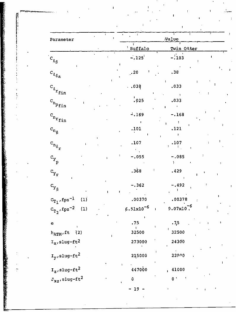
Parameter ,Value
'Buffalo Twin Otter
C -. 1255 -.103
k6a
c .03q .033 .C~rfin,
C .025 .033n Pfjn
C -. 169 -. 168nrfin ,.101 .121
C .107 .107
n6r
c -. 055 -. 085
Cyr .368 .429
C -. 362 -. 492
CT-fPS (1 .00370 .00 -378
CT2 ,fps 2 (1) 6.Slxl0 6 9.07x10 6
e .75 .715
hATMft '(2) 32500 32500
Ix,slug-ft 2 273000 2430Y0
lyslug-ft 2 235000 220n0
"Iz~,slug-ft 2 447000 41000
Jxz 1slug-ft 2 0 O'
-19 -
I I
I I
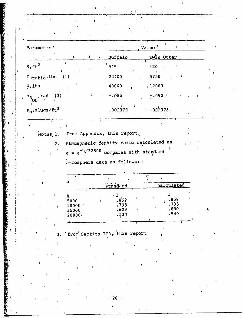
Parameter' I: Value'
Buffalo Twin Otter
Sft2 945 420i I I'
Tdtatic,.lbs (1) 22400 5750
jl,lbs 40000 12000
aB ,rad (3) ' -. 085 -.092OL
Poslugs/ft3 .002378 .002378,
Notes 1. FroM Appendix, this report.
2. Atmospheric denbity ratio ca1cuiatdd as
S= e-h/ 3 2 5 0 0 compares with standard
atmosphere data as fotlows:
standard calculated
I 0 .,I 1
5000 .8-62 ' ,.85810000 .738 .73515000 .629 .630
20000. .533 .540
3. 'from Section IIA,, this report
S-20-

IV Simulation Program
The equations of Section II have been programmed for real-
time solution on an XDS9300 digital computer at the TSC Simulation
Facility.
Because the simulation is a simple one, a flow chart is not
presented. The program listing, together with the discussion
presented here, should be sufficient to completely describe the
simulation. The listing is included in this report as Table I.
IV-A Interface with GAT-I Cockpit
Provisions are made to drive the simulation manually using
a GAT-I fixed-base cockpit modified for the purpose. Commands
from the cockpit are:
Elevator trim (ELTRM)Longitudinal stick displacement (DLE)Lateral stick displacement (DLA)Rudder pedal diaplacement (DLR)Throttle setting (THROT)
The scaling voltages used are given in Table I.
Similarly, the display quantities presented at the GAT-I
panel (listed in Section II-E) are scaled as shown in Table I. '.
iV-B Definition of Initial Values of Variables
It is convenient to be able to begin a simulation run with
the aircraft trimmed at a level flight condition. Accordingly,
provisions are made in the simulation for inputting desired
initial conditions, and then for calculating required initial
values of other parameters to produce a trimmed flight condition.
- 21 -

Non-zero initial values are normally input for altitude
h(O) and airspeed VR (0). In addition, non-zero steady state
wind values can also be specified. Zero initial values are
set in the first computer iteration for these parameters:
U, V, W, P, Q, R , 0, P, Q, ,, R,
, 8, , vw, ww, xL, L YL, a, ,
An initial computation is made to calculate initial values
of other parameters, using the following equations:
a e e-h/hATM
P pap 0
1 V 2
q=�p VR
Uw =VR
L = U = R + w
L
L L
i ~CL = CLo = W/qS
CD CDf + CL 2 / reAR
D CD qS
OBaBo CL/a + aB
""6 0
S=D(l +C VR + CT2V 2)/' c
- 22 -

The last two equations define required pilot inputs for
initial trim. In the simulation, provision is made for
inputting these trim values for a specified length of time,
after which the actual control signal from the cockpit is
used. The magnitude of the delays are TMTHR seconds for
throttle setting ý, and TMDLE seconds for elevator input 6 e
This scheme permits setting up an inital trimmed condition
without the need for cockpit control manipulation. It is
useful when, for example, step response runs are to be made.
-23-
V Simulation Results
Simulation results are presented in this section. These
results are in the form of time responses to various step control
inputs.
The time responses are presented in a manner that permits
direct comparison with the linearized results generated in
Appendix D of Reference 1. In general, agreement between the
two sets of responses is very close.
It should be noted, however, that Reference 1 and this report
utilize the same analytically-derived data. Therefore agreement
between these two repurts does not in itself prove the validity
of either set of results. This proof can only be obtained by
comparing the present results with data obtained from some other
independent source. Unfortunately, however, specific data on
"Buffalo" and "Twin Otter" responses from other sources are not
currently available.
Accordingly, it is possible to say at this time only that
this report is consistent with Reference 1 and that both sets of
results are "reasonable". The time constants, frequencies, and
damping ratios of the various modes presented in Appendix D of
Reference 1 agree with results presented in this report. The
values of these parameters are in the expected ranges, and show
the normal variation with airspeed for each aircraft. Similarly,
control power values appear to be within the expected ranges and in
proper proportions.
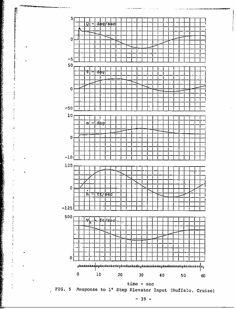
Responses Shown in this report are for the Cruise Flight Con-
dition. For the "Buffalo" this is level flight at 400 fps andi -24-

10,000 ft altitude with a gross weight of 40,000 lbs. For the
"Twin Otter", cruise is defined as level flight at 278 fps and
10,000 feet with a gross weight of 12,000 lbs.
Figure 5 shows the response in pitch rate Q, pitch angle 0,
angle of attack a, altitude rate A, and forward speed U resulting
from a 10 step elevator input 6 e for the "Buffalo'. Lateral
degrees of freedom were suppressed during this run. This figure
compares with Figure Dl of Reference 1.
Figure 6 shows the same information for the "Twin Otter". This
figure corresponds to Figure D13 of Reference 1.
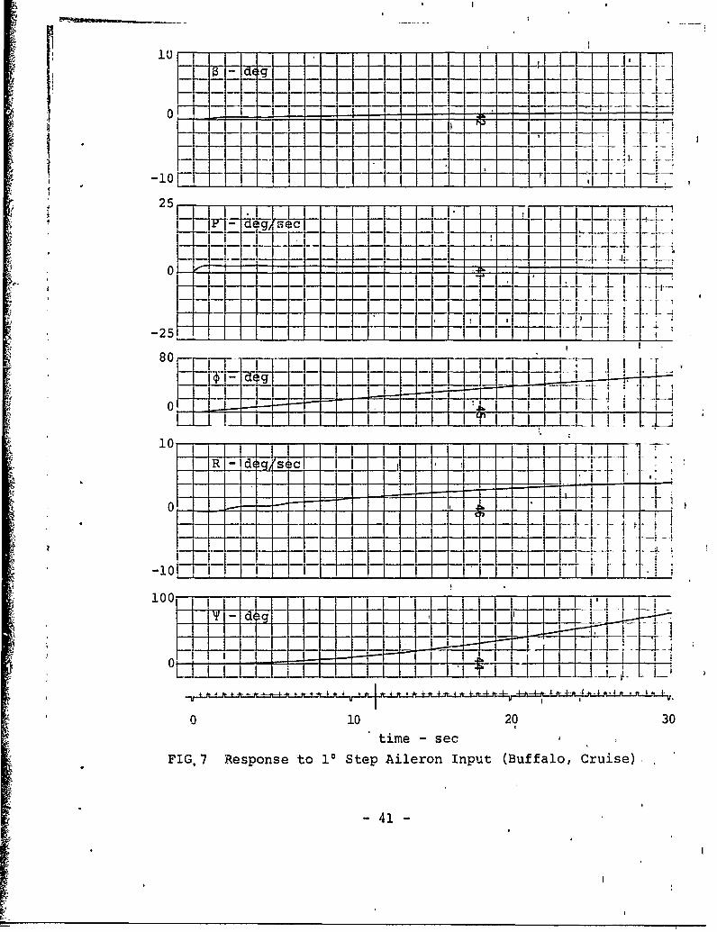
Figures 7 and 8 present lateral responses for the "Buffalo".
Here, longitudinal modes are suppressed. Figure 7 shows the re-
sponse in bideslip angle 8, roll rate P, roll angle P, yaw rate R,
and yaw angle T resulting from a 10 step aileron input 6a. Fig-
ure 7 compares with Figure D7 of Reference 1.
Figure 8 shows the response in the same parameters resulting
from a 10 step rudder input 6r" This figure corresponds to Fig-
ure D8 of Reference 1.
Figures 9 and 10 present latiral responses for the "Twin Otter"
for 10 aileron and rudder inputs, respectively. These figures
correspond to Figures D19 and D20 if Reference 1.
-25-

References
1. O'Grady, J. W.; MacDonald, R. A.; and Garelick, M.: "Linear-ized Mathematical Models for DeHavilland Canada Buffalo andTwin Otter STOL Transports", Report No. DOT-TSC-FAA-71-8,Transportation Systems Center, Cambridge, Mass., 02142, June,1971.
2. Perkins, C. E. and Hage, R. E., "Airplane Performance,Stability and Control", John Wiley & Sons, Inc., New York,1963.
3. Jane's "All the World's Aircraft", 1967 Edition.
-
-26-

TiBLE I
SIMULATION PROGRAM LISTING'
C.****REVISED DATA FOR SUFFAL9TER MG 6/16/71C ~REW1:-X, rIYZ -
COMIION/CONST/WEIGWTDRHSSEA.HATMJ AaBeC#SsEPIARI*CT~S*CT2#CMTP
2 CNPFINCLBJCLRF!NCLPCLDLATSTATIX*IYD!ZqOBM PCDF*NVEH;y1TYPE*;
DATA NVEH/21/DATrA WEIGHT;RNBSEA,SiATMALFBOL/a000OOQOe.0237$,32500,O,.,o85/,DATA AI8,PCgSEPIAR1/5;2,96.O,1OojD94590g.O435/DATA CMTotCNALFpCmDALF CMOCIIDLE/0.Og..78,.6.05,.35.62,212/DATA CYB.CYRDCYPCNlICNDLRCLB/..362,.3468,.,055,.1O1,.01071..9125/
---0XTX LN tINLPTTNLMqFTVtLp, t'C6LsX7.. 169. .035, ,038, * 53, 20/DATA CTliCT2*DELCD,,TSTAT*CDF/ 0037,'6!6.l1E6,.Q3,22400sol*3p/DATA I'X, Y, !Z/273000.,215000.,41.7000./IENDBLOCK DATA --
Ct****REVtSED DATA F'OR TWIN OTTER MG 6/16/71J ~fl~X,1~TTCO'"ION/CONST/WEIGI4T,RHOSEA,HATM# A,B,C*SEPIARI,CTIPCT2,CMT,
i 1I C'MALFCM 1DALFCM0,CMDLECYB.'CYRCYPCNBCNDLR,CNRFIN,DELCQ,t 2 CNPFtN#CLBCLRFIN,CLPCLDLATSTAT,IX,IY,IZtOOM ,CDF,NVFH#NTYPE#
3 ALF8OI.
DATA NVEH/20/
DATA A.#B.C,SEPIARI,5;2,65.0,6.bJ42O.O,.D425/DATA C!,T*CMALF,CHDALF ,CMgCDLE/O0,..-78,.6.15,.?4.6,1.73/DATA C .oCYRCYPCNHICNDLR,r.LB/..492, .'29,-.085,.121, e107e.1G3S/DATA CNRFNCNPFINgCLRFTliCI'PCLDLA/..16Bp~eO33,,D33,..53,.p38/DATA CTI.CT2,DELCD,PTSTATCDF/,003774,9.C7E-6,eo3b,5750.,,039/
ENDC MAIN PROGRAM4
DIMlENSION DERIV(12),VINT(12)REAL LIFTLV3LRLPLDLANVNR,NPNDLRIXJY,IZ
x COmM O1N/aLlPRN/BLPFRQ, !TTB, IBLIPPRN~FRQ, ITTP.!PRNC"'1%7ZST7WET"%3T7R1MtA,RXTM# A,,B#C,S*EPIAR,1,CTICT2,CMTO1 CMALFCMDALF,CMQ,CIIDLEPCYB,CYR,CYP,CNB,CNDLR,CNRPINI,DELCD,2 CNPF1%p CLB,CLRFIN,CtP;CLDLATSTAT,IX,IY,TZ,8DM ,CDF,NVEH#NTYPE,3 AL.FB0L
Cel5Nxss, ySSZSS,#RNAX, RNBX, RNAyppNByIHNAZ, RNBZ, xk wyy,*I WZZXSDYSD,ZSD,XTAUYTAU,ZTAU,JXJYJZSGUSTPUWP,VWWW
C H.tlN RHe,SIG,DYNiCL , D~yV'Y oYP LV *LRLR,LPLDLA#NVCNR,I NR,CNPrNPNDLR,CM,#DELATICOM~tON ELTRH,DLE,DLADLR,,THReTGDLEGDLA,GDLRGELTRM,,I TRNPNT,SL1P6LPTCHBjRI I
COMIMON ALF,VRL IFTDRAGDALr,THRUST,UDeT,,.Da!T, GDOT, vufT,PDU1,
2 PHI,X*Y#H,BETA TFApICO9"ON CLO,ALFBOEQUIVALENCE (DERIV(1IUD07),CDEqIVC2),W6oT),CoERIV(!3),a;VOT,,1(DERIV(4),VDnIT1, DERTV(5),PDOT), CDERIV(6),RDOT), (DERIV(7)bTHETDOT
-2)ao(ERIV(8)PPSIDOToT(DERIV(9,P4iiDOT),DUERIVCIO),XDflT),(COENlvU1I,
'3DTPtTET~ 2T*Wl(7T(I)aU (V INT (2) 1W ) (V INT (3).), g*( V IN T( 44)IV),CVINT(5),P),(VIN4T(6),R),(VINTC7),THETA).(VINT(R),PSV.*(VINTC951,PIIII,CVTNT(1IX),,p(VTNTCII),YC(VINT(121,H)NAMFLIST H,VRX,YPSIePHIP,QRV,DEL#NTYPEWEIGHT
x NAMELIST ELTRMPDLEonLA,DLRTHROTNAAFLIST TMTHRTMDLE
-27-

TABLE I (Cont)
.2.L NAMELIST 8LPFRODPRNFRGrNAI-'clis 006to [AULAp ULF6Ro TqNFWTYPILD'PW TtRUW-tWLTRm-
C. NAMEL IST XSSDYSSD ZSS,XSD,YSDZSD,XTAUYTAU.ZTAU,JXJY,JZIC.
CALL SETP"t r32,3ooo,2000,O00 1000O)CALLI SETPOT (132,3000. 2000.0000. 2000)
12 NTYPEUOCOW*** CALL STANDBYs S .ý 031010
C**t QES/SEC/POINTER WIDTH FGS RATE OF' TURN'RWi '81991
ICWVWTW-l D0E1ThRtCWITrrW FVR VTP'SLPSL85*73
C#90*.. 4 DEGY6AR-WtbTH FMR PITCH
PTCHBR8.149325
C*0*2 nEG/VOLTGELTRMDGDLEa .0349066
C**e** 2'3 OF.IS/VlLT-I3DLRu-0116356
COO*** 4/3 DEG/V"LTGDLAs-90232712
1C
IHa6CCO.VRasc0.
p YuPsI:PHImPvQ.H. TMTHRmTMDLEuZSSUOoBL SPFR..410.
x RNFR4'.u1
XSS%14
XSD-.23YSD;1-6ZSDSI.XrU.SYTAUZTAU.1 .5DELa *05
A * CALL IF1INITIA
C."..* CALL C3MPUTEG EeV 031013
x ITT~e.TEOP
X .TEmPwPRFRQ/DFlr
x IBLIPOTPRNS-1OOM;32e?/WEIGMTDO 1 19
1 DERIV(flm0.ij SIGOEXP(-H/HATM)
RHtuSL0.GRHOSEACLOw2o*WE IGHT/(R1460SOVR#VR)ALFtI0.CLO/A+ALF!IOL
IF(SENSESWItCH5)20,2120 CONTINUE
UNVR*XSS
'wZSS

II TABLE I (Cont)
06 TO 2221 CUNT I WE -
Nova0.U 'yR
*22 CONTINUEVWaiwu0.UWBVR
DYNO. 5*RHB#VR*yVAbRAoC.D**DYN*SDRAGIvDRAGALFImALrVRIxVR
TO-DELQNA~1..DEL'XArU'RNAYaI..DEL/YTAURNAZ.1 .-0EL/ZTAU
-~RNBXsXSDOSORT (2**OEL/XTAU)
NNBZoZSD*SQRT (2. .DEL/ZTAU)SGUSs~ S:RT (XSS.xss+YSS#YsS)CALL ARM(0)CALL ENINTCONNECT (40, AERO
C.....orE L5"P + TEST-~trE CXSM OF AERU10 CONTINUE
X 11 CALL AERBCv**.. IDLE LetVP + FAKE INT*00 USING r/FT*L.,S*Lo IF INT. SYSTE!" DOW,S SKS M0304S BRU $-IS Ee- 0330004S Eem1 030200
IF(SENSESWI`TC~in 12,10ENDSUSQ5QTINE AERODI!'ENS!ON BTE(3#3)0?mEF~a-tRTV(12YoV1NTT12)REAL LirTsLVLR*LPL.DI.ANVNRNP',NDLRIXIYIZ
X COMMON/9LIPRN/BLPFRn, TTBTOILTPPRNFRcQtTTP,!PRNCeMr.8N/CONST/WEIGHTRIIOSEAHATMi A*BoCS#EPIANICT1,CT2*CMTP1 C'¶ALPC?¶ALFCP4QCM0LECYBCYRCYPCNDCNDLRCNRFINDELCL~,2 CNPFIýNCLBFCLHFINCLPDCLDLATSTATJXIYIZOem PCDF*NVEH#NTYPLP
C~M~eN XSSYSSZSSRNAXRNE3XRNAYRNBYsRNAZDRNlIZ~wXxWYY,1 W7ZX3DYGDZSDXTAJ#YTAU, ZTAIJJXSJYoJZSGUSTUWVJ,hwwC,)mmt!N TMTiRT~'DLE.,DRAGIALFIV'kdSIGI
Cem-9.4 RHOSI3t,DYNCLC0,YVYR1 YPaLvCLRLRoLP,#LDLANVCN.i,I NR,CNP,NP,,JDLR,CM,0ELT
FLTRM,DLE;DLA,0LR*THR0T,3DLEoGDLA,nDLR,GELTRM,1 TRNP'JT# SLPL8L,PTCHL1RCt!%A~sN ALFVRPLIFTDRAGOALFTIHRUSTUDeT,WD6T.,QC9T,VC9T,PDDT,
2 PHIj,xY,H,liETAC0O~wN CLO*ALFI3CEflIVALFE(4E-DEPIVc1),Ur)oT)',(OERIV(2),*iDnT),(oERIV(3bcGOoT)#I (DERIV(4),VDflT), (DEHIV(S),PDeT), (DERIV(6),IDO8T), (OERIV(7),THETJUT
3yDOT),(DERIV(12),HDOT),cVINT(fl,U),(VINr(2),h),(VINT(3),O),(VIN4T(4
5),PVl),(VN(P)p(T1,X(V!NT(1lI*y),(VINTC12),HET)(IN8)PI(VT9
-29-

TABLE I (Cont)
5 EO'l 030000C RECTANGUL.AR INTEGRATION
T4T#DELDO 10 ISIP12
10 VINT(J)sVNTC!,.DERIV(I)*DECC -M-REWt'C..... OLE FROM -10 V. DOWN TO *15 V. UPCOO-. CLA FROM P15 V. RIGHT75T +15 v. LEFTCo #.. DLR FROM -30 V. RIGHT TO +30 V, LEFTCoo*** ELTR41 FROM4 -15 V. DftWN TO +15 Vo UPC..... THRO7 FROM1 -3.2 Vt IDLE TO 0 V. FULL
CALC -tLZ.CTMDrL'*L TO)EL TRM1.GEL TRM E LT RMOLA . 0DL A*DL ADLRsGDLRoDLRDLEzGDLEODLEEL.TRM.THR6iT.1 +v3125oTHROT
C TOTAL VEUTfCITyVRSC*UW*UW*WJ.VW+WW.WJVReSQRT (VRSO)
C rALCJ)LATE COEFFICIFNTSSI~sEXP(-H/HATM)RHO .RHOSE A. SlnIFCT.ýjE#TMT;;R)GB Tl 81jF(C VEH. I0.P) S 101.THQrTUD.RAGI.(1.,CT1.VRI.CT2.VRI.VRI )/(S!GIOTSTAT)
81 iF(T..-E.TMDLE)Gn To 82DLEaC.
C 8 CONVtRISJ SUPFRCHARGED***USE SInaI FOR THRUST CnmpIF V~V'ýH.EQ.? Isi~mTHRUJSTOT~iROTOSIG.TSTAT/( 1 +CT1.VR4 CT2.VRSQ)C DYN'A1IC PRESSUREDY~s#5#RH*TOVRSQ
SPHIVStN(TIHY
STLI.5I%( THETA)CP~jwISC(PHI)
CTH;C2S(THETA)C.*O*OOOD 'TO EARTH TRANJS $4ATHIX(
S TC!;sST'I.CPS I
SS~sSosspr*SPHIsTEC V.1)*CTii#CPSI8TEC l,2)#STCS#5PpiI.-;SCP
BOTEU ;3) VS~TS.CPH14:iSrsP8TE (2, )mCTiI.sPSiBTE C2p 2) SSSP*STH.C0HI .CPS IBTF(2, 3)NSSCP*STH..SPHI*CPSI
BTE(3,2)u.SPHI.CTH8TE(3~il)sCPHIoCTW
C A~jW .:jN4) M'3DFLC FaSs ?1'2Ps23 De4.N FOR~ IUST IN XpyZ RESP#C SsS... 5 UET FOR STEAD)Y STATECS S'KS 331006
-30-

TABLE Ir (Cunt)
S BRU IIS ____
.JX82S BRU 12S
11 XGUSo0.S12 SKS 030007S BRU 13S
S BRU 14G13 y3UusO.
S14 SKS 030010S BRU 15S
GO T6 315 ZGUS.oe3 IF(SENSESWITCHSI40S4 CONTINUE
WYY.YSS+ CXGUS.YSS*YGUS*XSS)/SGUSTWZUgZSS+ZGLJSGO THi 6
5 vXXsX3USwYYaYGUSW770ZGUTJ
6 ceNTINUF:C40'.. SSDY AXIS VELOCITILS INCLUDING WINDS
VWuV.(*dXX*BTE(1,2),WYYwBTrC2,2.-WZZ*DTE(3,2))WWiNA-(IXXtBTEC1,3)4WYY*EBTE(?,3)..hZZ*BTE(3,3))
C AN13LE Ir ATTXCK,CIFT#'DRAG-ALF*ATAN2(WWUW)CL@A*ALF+CLOCDC¶)F+CL*CL*EPIARI
LIFTSCLOGSDRA'3zCD#C;g
C ST DESLIPBETAs AT AN2 CV W, Uw
C RVsuRvS,2 RVSBNRVSB/2 RV4uRVSB/4 RV4HI2mRVSDB/4RVSo.S.5RH9OVR*SyVapvs.CysRViSI*RVS#BRV4no.5*RVSBYRsPV'.*CYRY~vRV4*CYPLVRVSB*CLSCLWUCLRFIN..25*CLRMA21MV448LR*RV40Z.CLRLONRV4D?*CLPL DL A arS aBOCLDLAN VoR VSB CN8
- CNRoCNRFIN.-25. Cnf-!ELCC)f.J'@Rnv4B2*CNRCNPvCNPFIN.925*CL*(1..A*EPIAHI)NPGRV482OCNPND.'-R^S*B*CNDLR
C.C CALCULATE AERODYNAMIC FORCFS
-34

TABLE I (Cont)
CALFaCOS(fALF)
Ct**4*.LNGITUDINAL EQUATIONSCv**~if7f NTYPEw2F FLY ONLY LATERAL
- IFCNTYPE*NEvE;~3e TO 31 ---
00 TO 32
31 UDeTUOOMeCTHRUSWDRAG.CALFLIFT.SALFUWEIGHT4STH).QOW.R*VC -Z--FeICE -
WD0TRtBOM*(ULXFTCALF!.DRAGOSALF4WEIGHT.CTH.CPHI )+Q*Ui.P*v
DALFE CWDOT.WW.UDOT/uW ).CALF*CALF/UW
CMOCMT*CMALF*ALFC*95.(CMDALF.DALF+CMQ.Q )/VR*CMDLE@DLE
CCI*04;*LATERAL ElQUATIONS'C*..**IF NTYP~o1, FLY ONLY LONGITUDINAL
VDeTsPD8TwRDeTO#GO TO33-
C Y FInRCE32 vDOTIormO(YV*VW+YR*R4YP*PIWEIGRT.SPHI ).ROU+P*W
C .. .eMEX
C N MOMENTROOT' (NV*VW+NR*R+ýNP#P+NDLR.DLR)/IZ
CC EULFR ANGLE TRANSFORMATION
*33 THETDflTOQ.CPHI.R*SPNI11'STUWT' ( (rSPHl +,ZCPM7/TCTHPHI!)OTNP+PSIDnT*STH
CCC4*#** XD!T#YDOTI4DnT IN EARTH-FIXED COORDINATES
DO 35 1.1,335 UDRTVc?*919F'rrcr; 1*'-U*TTE(I a2) #V+8rE(I,3) #W
C* IF(NTYPE.NE;2)GO TO 34
HOOT aTHETDOTmosPSIDOTmR
* PHIDOTwP.3.4 L 0NrrT I E - -
CIF (SENSCSWITCH2)71,72
71 O8vTHR9T*1OoCCv*.#.BLIPS FOR TIME ON STRIP CHART RECORDERX- '121E: T~vF3RL IP +1x IPRN;IPRN+1x IF(I LIPfEQ9ITT8)GO TO 63X D88-25*
x G6 TO 64X 63 IE3LIPBO
X 64 CONTINJEDlu14 **005D2 *VR'elO38TWETA*143,25D40OLE*143*25
-32-
TABLE I (Coxit)
D5*P141*57*3 _____
* D7 2DLA*11496
COO*** NTYPEv 0 FOR COUPLED, I FORLONGITUDINAL ONLY, 2 FOR LATERAL ONLY.C-
IF(NTYPE.1)66,f7a,45
D6*0*57*3D7'FALr.143;25GO TO 66
65 DloP#57*3 - -j ~~D2v6ETAO286s5 - . .
LD1UIJLH*5$3-D04 PS1I0289*65
66 CONTINUE -
CALL DALC2ODI,02pD3p04*D5#0 6 j(,0)7#M472 CONTINUETURNOu.TRNPNT.7*5.PS DOT
C..... HDeT IN FT/SEC, INDICATOR IN FT/MINC.4... -6.67 VOLTS/1000 C1TMBs +8,33 VftLTS/10OO DESCEND
IF(HDfl.TvGT90#3RerC. #'40D2*HbeOT
VI<T!;VR~o59?.SgRT (RHO/AHOSEA)Ih(VKTS:PS.9)2 00 #2 jotplo
201 IF(VIKrS-44*)2o2#2os,20 8
Ge Tn 211208 A'IRSPDo..* 22*(VKTS-44*)
38 TO 211209 AtRSPO. 1748..O92*(VKT9.125.)
GO TO 211
211 CINTINUEACTwo0~2oH-809
DIRCPRN.-PSI*15@916667
DtRGYR*DIRGYR-I1oo,0
IF(A8S(ROLL) 9GT.99.9)ROLLUSItGNC99.99ROLL)PiTCH-5--PTCH8RO (THETA4ALF8O)RPmm3o+TH4ROT027*
CALL DAL(28#
C*.***P9I,,T.0u.T AT FREQUENCY PHNFROx IF(JPRNaNEto1YTP)00 Tn 62x jPR%,wo
X 2 DLA*57#3oDLRl57-3,OETA.57.ijX 101 FORL1ATC To*,P'8.2/3XSUDOTa eF11,4,#12X,$sU~gF1 1 .4,12X,.Vos*Fll.4,
1 12xpsw.esF~l, 4 , 1IXSVR*,oF11,4/6XSHU$,FI 1.4,9XSHDOTu$,F1i .4AX 21X$LOj148,TE~SF .soPt,1.,4~pIsX 3 F11.4$12XSP.*,FlI.4, 12Xi*Qg$,F11e4,12XpsR.SF11.4,7X,,THRUS T v~
-33-
TA13LE I (Cont)
x 4 F:li 4D/2XSTHReTsOF11 .2D41XSLIFTe$,sFl1.4,9XegDRAGuSDFi1,4D lOX*
iX 6 F1 1 .J4 ///)X 62 CeNTINUE
C*00** TNIMNG SM0ALP RESET"FYPFS EOM 030001,
END
-34-
01(04 TWIN OTTIR following last& refer to the currenit production tab.a io rudder and port elevator, latter litter.- Aiionrd i Agus 184,th Twn tte mdel, connected with flaps. Pneumiatic do icing
a STOI. transport pwered by two Pratt &t onrz pwntrb o leadin edgenotionalWhitney (UACI PTA.20 tue orop engines. Tp:Ti~ulorpSO.tasotlleoign work began in January 19 4. Construe. L.ANisNO OCAxý Non-retractabile tricycle t51 w..
tii f niita atho wi ter e satd Wilos: Blraceil high-wning mionoplane. with a with steerable riose-heel. Rtubber shockin Novemiber of the msa' year and the ffist of single staresnilinosection bracing strut on each abmsorptiona on miain units. Ol~eo priesniatotheme flew on Stay 20. 1063. side. Wing section NACA GA series mean line; nose wheel shockltabsorlber. Gooidyear mntall
NACA 0018 (modified) thicknesus distribiution, wheel tyre size I11.00 x 12, pressture 32 lhfitn it;At the beginning of 1967, a total of 52 Twin Aspect ratio 10. Comfotant chord of 8 ft 8 all 1225 k.8(cn'f Goodyear nose,%heel tqre mitt-
Otters had lieeii delivered or were onl order, with (189 in). Dihedral 2'. Incidence 2* 30' 890 012-50, pressure 31 Ilbsq in (218l kgfrofl.optloats on I I more. They included eight for the No sweepback. AIl-metal safe-lifel structure. Goodrich lixdrisulie brakes. 1'rox ision f..rChileais Air Force. two for Trans.Australrio All-metal ailerons which also droop for use as alterstixte float &and ski gear.Airliiiem. one for the Canadiasn D~epartmient of flaps. Double slotted all-netal full spaiiLeniiil and Fori~ts. four for Aeralpi of Italy. trailting-edlge flaps. No spoilers. Triin-tabs III P( ~I.P A%? Tuo .779 enlip Piratt & Whlue)otie for Northernt Coinoulidated Airline., and aileronst. rneumnatio-hoot de-icing equipment IL l Ao mrtiopegns caiothi're for l'algrini Airlines and Air Wiscoiisin, optional. drivin Ma Ilete thr.bloperep eenilmem.PartlUSA. Production was scheditleil to be at the duriving Hatzerlgmtl liroellde r. ~ibleaniete 8rato of six a month through 1987. FuoXLAOZ. Conventional al-mnelal sentmiiono. 0 lyfein 1244 nil fuel toltank (8rels d iaieter Nf
Uiider idevelopment for idelivery i11 1988 iii a coque safe'life, structure. cabiii floor:. total capacity 919 Inmp Xallomixversion of the Twiii Otter with more powerful (4.17,1 litres) Tuo refuelling point. oait1smet(640 "ohpl Pratt & Whitney IPr8A.27 turboprop TAIL UNITi: C'antilever all-metal stiudture of side oi fuselage. Oil1 capacity 2 Imp, gallonsengines, longer flume to provide more baiggage high strength aslurnmniwn alloys. Fin integral 19 Mitrns pr emngine. l~letrje de iciog x .t i
.pace. waiit AUW of 12,300 Ilb 15,870 ligl. The, withfuselage. Ftzedlamcidence tailphane. Trim. for propellers wand Air-iltakie optional.
J2
IA 'IS in')
= rr orfegtcmatetadbgae1 -. -
se n ato ati. sieabh with o fparlgh Widlthi 40 8 in (0782 mn) Taxlpalane fo 0 ml 10.1 sq ra(3nfl)hanged deatr onfort 13s assengr Hnmin eight to sill 3f 0 lan (1117 ml) 4l.4r. nlin al 35 sq, (200 Let nfra in Cabin div de f~ by bulk e .ad i to m ain D Ileggage S co m partm ent M aor Tno e) epalinIontis,:s Vpasengr0 o fregh coempari ytment an Oagae Caeight toluin si t 30ck 10e and baggag Sfa) lend~rin~ag %eight, 1,0 iei lb 14.10 0 l fl,or0 :to &Mie ompgtent.Door on ec eachgide. of tollaetcompartnment. ilor(or, er) 7 on adtiteo (a0t ma TOwegh)
tollsaite'op liiaggage compafyigisrt iao. Max wigtht 5 It 3 in (1270 nml 8ru 19kumnos and aftoa bid a ch. with upar.eighth 40 A IIin (141501 n lx payloa (forn s~l 10.00 ftie (3.05 kni ra)hingex dorat ont portIML Floside.2* I 74 ) 5 p (3 nhWing$pa 63fs hydaul s1tm prssr 1110lot Volueih to4 sil 30 l(in 817 m) Ian11 pet 64.430I11201 kinhsq xg(10 overanll for flps brke ind nose 09 xtimoe anL Roleof claninb aegt S1, 1,.440 lb (4.69 in I'twHeigh sovering. No pnu ti systemS. One Csb Iexelg cmorting lgt ileek. galluey and ~ ca bagiggage t7.7 l.bOAlll tarereneao on eac engine,64 n)2 uI or tole ronarlelt lxarv eiling.on (trie oax T .500 fotl0.30nWeaelotc fre D 12iuit ftad3oind(-7. rada Ileiigtha 140atie (f inr (54i) onculoupedam1.o0(300m
tocustumer'.speciflcation.~5 Cail'liniotu Snwdh5 In (1807 nlot T80 toin (28 fti(om)Wheelbatinse adr.Sa heg4 40 VI ii (4150 nn) 9.n 1risn s1e at 1000 (3 415 iii)Poitiona doors (pot aid-). A lorAM aCes Ptsc 3t(4 1.7; 041k 1318 nIthWingspa 85 A in (1987in Map grolume0q 3 ( 3u 0 218 ma) lani~ng speed 845 mph (lt nniliLemith ovrl 49 0 8r (07 n ieos(oa)3- a I 30 ,) SO .2 t41 u
Heigl to~a sil I tla , otmaln-eg lp (t8tal) 12 2csal (1082 nfl( CARviePtngonegi3e 8,002.16 6sitl
Passenger door (ptroart side): Finos 48 C0l Pqf 44 i) Rnewth ma f.uel. 351 mal I
Heigsht 30 R 1in (1-13 nil Rtudder, Including tab 34 0 sqsI (3-18 int) 928 Itaies (1,4n0 kin)
Source: Reference 3 FIGURE 1
-35-
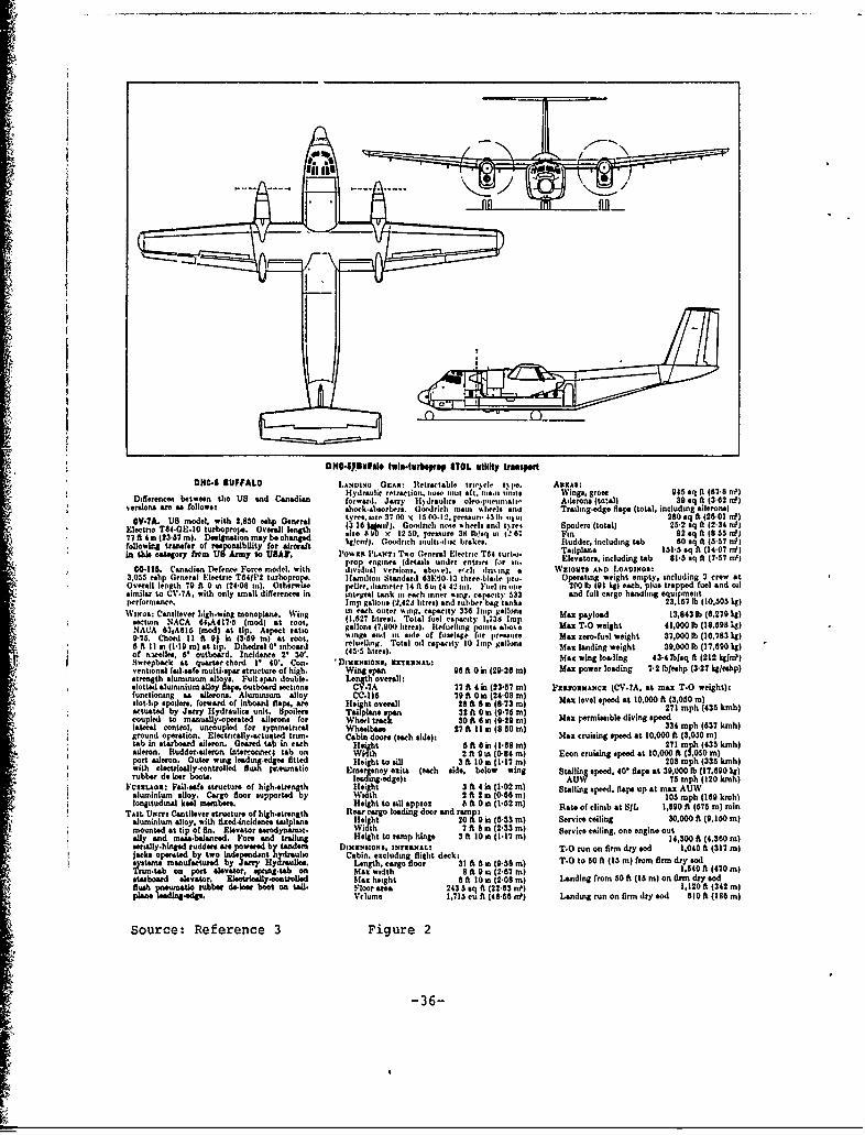
ONO44.SJollol 1111411111riliprop STOL otility transportDl(C-S 11UFFALO LNINGerlv GERoa Retra~ctable, tric~cle rpe ARICzA$,grs
Hydraulic retraction. now. urol &ft. iti.l lam:. Wngrcs 945 sqt ft (87-8 nflDifference, between tho US and Canadian fowr.Jry l~ruisoleo-pneumall Ailerons (total) 39 sq ft (3862 rd)
.ersions are a" follows; s&hodaw bsrle-wr1&r,~. Gooýd~ri~c~h m~iaul mhee, anal Trailirg-edge flaps (total. including ailerons)
OV.TA. US model, with 2.830 oslip Genrl tyrro. size 3" 00 xc 1500.12. preuour4311b .. ju 280 sql ft (26101 )Eleetno T64.GE.10 trooo.Overall legh (3 16 Waif). Goodrich no,, tiheels sild t% r- Spiero (total) 2532 sq ft (2 34 nfl
tuhoroe is 8 VO 12 So. prtr 36 lb,'. in 1. 6; , M 92 sq ft (8 63 to)77 ft 4.(23857 m. Designation may bso~no ekln) Gorc mlid baeBudr.ncuigtb 0olftJ-7Hfollowing transfer of responuibility for aircraftorc nut~as rks Rde.inldn ab 8 qft(5 f
*in "hi catesgoryr fie. n usArmy to us"?. l'owIA PLANT: Tao General Electric T64 turbo. Taiplpina 131I5 sq ft (14-07 nfl
prop engines (details under entries fro in. Elevator,,. including tab 8135 sq it (7.57 rni)M11158. Canadian Defence Force niodel. with iividual versions. slo,o'el. th ilri~ing a WzICONS AND LOADleOst
3,033 ethp General Electric T841112 tuirboprots. Hlamiltoni Standarid 831.50.13 lhree-llade pro. Operating weight empty, including 3 crew atOverall length 79 ft 0 in (24,08 in). Otherwue pellee.dilimeter 14ft Gsa(442 rai. Fuel inione 2M1 lb (91 list each, plus trapped fuel and oilsimilar to CV.7A. with only stmall difference" in integral tank ii, each inner Ring. capacity 533 and full cargo handling equiMeGtperformance. Imp gallons (244244 litres) and rubber haag'tanks 23,187 lb (10.530 lag)WINGS: Cantilever lalgh-wing monoplane. Wing eac outer %ing, capacity 336 Imp gallons Max payload134 l(620kl
tip.nNCA66A1- Imd atroot, gal27lon rs) Total fuel ca~lwiaty 1.7,38 Imp 1,4 b(.7 g7IACA 63,A$16 (mod) at ti.Aspect ratio glos(7.900 litres). Itefue hog8 poinits aloe Max T-0 weight 4 1.000 lb (18.598 lIgl)9-73. Chord I I ft 91 in (3.59 m) at root, l1ogsard iii side of fuselage for pressuare Max nerofrunl weight 37,000 lb (18.783 kg&)
8 f IIin I~I mlat ip.Dihdca o'sntoarl rluelag, Total oil capacity 10 Iula gallons Mxlnigwih 900l 1.9 gof nvcelles, 61 outboard. Incidence 2130'. (45 lItres).ig egh 900 b 1.0 i
Sweepbsick at quarter chord 10 40'. Con. 'Diuizmsoms. grXaTXXALt Max wing loading 43-4 lblaq ft (212 kglrnPlventional fail-safe multi-spar structure of high. Wing span 98 ft 0 in (29-28 m) Max power loading 7-2 lbleehp (3527 kgleshp)
srntalwnminium alloys. Full span double. Length overall:.s llotdawninium alloy Shiap, outboard sections CV.7A 77 ft 4 in (23857 m) PZanoXAauNCX (CV-7A. at max T-0 weight):functioning as ailerons. Aluminiumn alloy CC.116 79 it 0.t (24.08 m)slot-lip spoiler,, forward of Inboard fla ar Height overall 28 ft 8.i (8.73 ml) Max level speed at 10.000 ft (3.050 Mlactuated by Jnry Hlydraulic@ unit. apoliler, T&I.a M spa 32ft 0 111 (9-7fi m) 271 mph (435 kmh)coupled to manually-operate ailerons foe Wheel track 30 ft 8min(9-10 m) Max permissible diving speedlateral control, uncoupled for sy~ninetrical Chelabi soo eahd) 27 ft I I in (8 50 ml 334 mph (837 kmh)
gcound oertion. ,Electricallyacetuated trim. Cai or ec ieMax cruising speed at 10,000 ft (3,050 ml)tbIn sabard aileron. Geaured tab in each Hle' ht 8 ft a in (1.88 mld 271 mph (435 kinhl
aileon.Rudor~ulec~nIntrconec ta on Waf~&drn ud~-drniteenec a nh 2 ft gin (0-84 m) Econ cruising speed at 10,000 ft (3.030 mlPort aileron. Outer wing leed!2.edge. fitted Height to Sill 3 tls 11 l 0 p 35khwith electrioally-controlled fl, prneumativ E (eac sid 0 in(bel n 0 oh 33k
rubber do ler boot(.acnh 0id exitsow wing Ststlling speed. 40' flaps at 39.000 lb (17,690 kgs)
FVSxXuoxt Vadlsa~fe structure of high-st~renlh H t 3 ft 4 in (1.02 ml) Staliling speed, flaps up at 7m ph (10 mhaluminfumn alloy. Cargo dloor suppor W13 mph 2ft89 kmhlongitudinal keel moembers. y Height to sill approz 6 ft 0sin (1.52 m) aeo lnba I 1,80 fth (176 kmlm
TAmt Usre, Cantilever structure of high-steenath Rear cargo loading door and ra p Raeo lmat81 ,9 56m i
alundinum alloy, with fixed-incidence tailplana He[ght 20 f 9 is (8553 m service ceiling 50.000 ft (9,150 mljmounted at tip of fin. Elevator aerodynamice. W idth 7 ft b in (253m Sevccilnoengeot
ally and masaobalatneed. For, and trollin Height to ramnp hinge 3 ft lo0n t(.7 ml 14,300 ft (4.380 mlerilty-hinged ruddero, ace powered by tandem DissaustoeS, INTlXaNAL: TI.0 run on firm dry sod 1.040 ft (317 ml
jaksoome b wo independsnt h ifraulbo Cabin. encluding flighit deck:systM. anufactured by Jaury Hyauis Length, cargo floor 36I ft aini (9.5g ml T-0 to 0 ft (13 m) from firm dry sod
rntaon port elevator. .p=Sn.taks on Max width 8ft 9 in (2867 ml 1.840 ft (470 mlstarboard alevalor. EioouJy0told Man height 6 ft l0 it (2,08 mn) Landing from 50 ft (15 mld on fin dry sodflush tismtc rubber deoees boot on tea. Floer area 24355 sql ft (22.83 nfl) 1. 120 ft (342 m)
po ldigog.Vclume 1.705 cu ft (48.58 Hf) Landing run on firm dry sod 610 ft (188 ml
Source: Reference 3 Figure 2
-36-

L: EARTH LOCAL VERTICAL COORDINATE FRAME
C: EARTH-AIRCRAFT CONTROL COORDINATE FRAME
A: AIRCRAFT BODY COORDINATE FRAME
EULER ANGLES
= ROTATION ABOUT ZL AXIS
0 = ROTATION ABOUT YC AXIS
= ROTATION ABOUT XA AXIS
S-- ,.-EARTH HORIZONTAL
I N PLANE
X ASC
X L
X T
East Y A Z ZA
Z
0
Figure 3: Reference Coordinate Frames
-37-

(a) At eguilibruim
XBO
XA0 o x
(b) Displaced from equilibrium
XB
V* XA aB 013
HORIZ. REF.
Figure 4: Sketches showing Relationship of A and B Frames
-38-
II1IQ-1 de •g --
"-5 - -
-50
_ -
1 0 I:Izj;-10
125 _ _ . . _ I0--
--10 r -_r-_I
S5 0 10L.l . 2-- -- 30...56III .. II •~ _" _""
time - sec
FIG. 5 Response to 10 Step Elevator Input (Buffalo, Cruise)
m- 39B

51 t/ / ! I i t t _i JI II I T f!II1_1___ __q- _1 _L_L_ 'B__L L _
fI-._-Q• t!_L!_. 1: _ i__1- - VI! L~
-i -
al-1. deI
-1 li '•L• 7 'Fl~
12 _5 , L. .. -_F -7 £Lz 1_ __..
-•_h tt-Hq -F - , t• I-H
-125 I ,_
-L 1~ 1 1 1
50 1•I 20 3040 1 50__H ,,I ! _i:I" ''Ua LL:
t e -s
Il j c - -ia q _~ -I-- - - - I 1--I t !__1
- _oL__L_tzJ - i .l!iz v i 1, • ~------iiL_~j--l
br-Tr I -•-Ti1t "T 1
FG6 Rsos to1 StpEeao Inu (Ti n Otte, Cri se
40l iiiI i i, i!j I i I_ _ i -_ _
SI ~1 i ] t!! q-J; -! -ii- ---! _. 1. IE!_JL _L
_!_! ij ! _ ___
Ii.-- -___--
0 -. I.- 1----- 1
V 5°°----- - -- 1'*
time -. sec
FT. esoset tep1 Eleat r TEnpu (Twi Otr, uie
0 10 20 30 40 506
, g i ' I-
0 t -4--
110S- - -- - - -
SI 2------------___ _1i I ÷
80 -- -i- . _ I
R- -I C.-..__ 1_
-10-
liLii
+~*~ + 4111 4-- - -44 Lý4 - -
0 10 20 30
time - secFIG,? )esponse to 10 Step Aileron Input (Buffalo, Cruise)
t41 -
FI.7 Rsos o1'Se ieo nut(uflCus)
- 41

10,.4', I , i li-l-t :. ..L i I il_,l IJ..
•, ,I ; I • !'! _LL ~i ii: :L- ii ' '1 -7
* - -i - I r " - - 4 _.j
-25 j L; -"deig/sjci J ,-i •-I , F T , "-i-
:-.• . . . . .. , -. " '- 1-. .- *-.. - - - 1 . -- -- , ..- I- • .• , .
" "- - .... . . -- --- - ...... 'i zz". . . . . -i-' "i "
oI••. I _____--T____-r q, . . .
1 ?FVF4- ' I L - -- [ -T- I I -i ] - '
,K' - .i- , -r• -i. i... . . ,. ... ; i
m80 _i _ " '1' if -if fI---J I--V1- iT---• TI ,-11- I-T "
S ,-I-_ F !__•I-,, JZ _-__-!T- II I - - -"I"o I • ! - -- •- ,I _ -" l i i l= ___ • i-
• ,~ * L L L.L.-I A iL L I._Ld : >.L~ i 1iI_.Li.L . ,0 LL
10
tie -secI II
0. -J42- l
-1 1 - - I . ... ..L -1- L 1 . 1 - --L
•:0 10.... 20 30!i •time sec
FIG. 8 Response tolj l__ Ste Ru de In u ( u- -1-1-1- i--se-,)-
•!,:i• ' :._• it- a•T.,•h• .-!-I-.t-•L42

-10:
25~1 jP iI e
-25..
7~P d ~sec
I] ° . j! '"
0 I 20
v[I !2,_• . 1_i_~ J 2 . 1 '
-25, ,iZ,_..... I_ _ _ _ ___I_ _
t ' d g !i • I .
-10 1 i i _ _ _ ! i ' i:
: i-jT W tisec e. - sec
* I *
. 9 s o 1, Se A In t ( O ,rse
0 10 20
FI .25esose t 1 te, i leron Ipu (T in te, rie
8 ° • , ! ,- . 43 - , , !

P !qE F ~-' -I-]
ifl I
-10 _ 1-25-.
I~ r T
1-1 !-T
L- -L- L- I L A-A
R I'
0 t~~j~i-I- -- *ý-
810
ILj [171i.i. q1711 9_L L
I-- t j--I
1 0 10203
time - sec
FIG. 10 Response to 10 Step Rudder Input (Twin Otter, Cruise)
-44 -

Appendix: Development of Expression for ThrustThe longitudinal force equation of Section II includes the
total thrust force T. Since directly applicable data on the pro-
pulsive system installation of the "Buffalo" and "Twin Otter" are
not available, an expression for T is developed here for use in
the simulation. Although the expression is adequate for the simu-
lation documented in this report, it must be considered an approx-
imate one.
Thrust developed by a propeller is
T = i PV4
where P is the power supplied to the propeller, V is the velocity
of the propeller with respect to the air, and np is the propeller
efficiency. Power supplied to the propeller is expressed in this
report as
P =oPo 0
where a is the atmospheric density ratio, Po is the rated power out-
put of the engine at sea level, and * is the pilot's throttle de-
flection, expressed as a fraction 1.00 :1
of the deflection for rated power. ]17i-"... e.
Propeller efficiency, np, is
obtained from Figure 3-17 of 60 -
Reference 2 (reproduced here) * : .... .11
.20
OEEIIO0 1 2 3 4 5
J/CId"
F i(.tIu 3-17. h opt h O k ll0 , ,u, •, (111"0.1.,.. --ibh .
- A-1 -t[
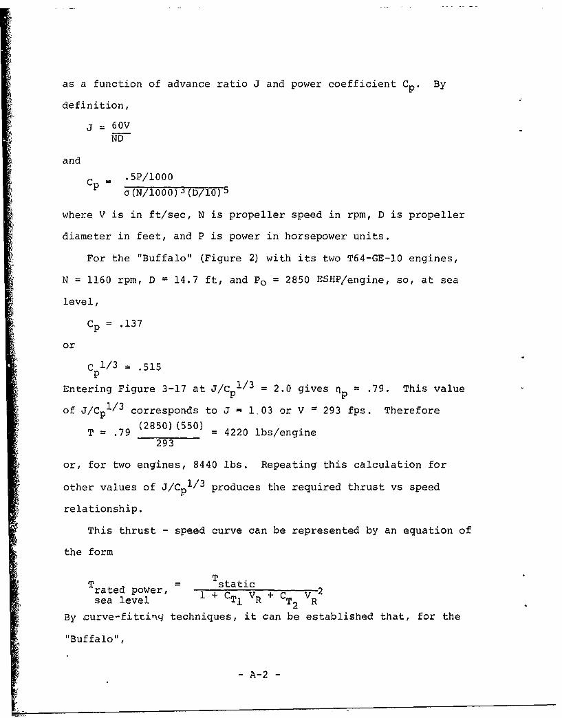
as a function of advance ratio J and power coefficient C p. By
definition,
j = 60VND
and
Cp -. 5P/1000a (N/1000) 3 (D/10) 5
where V is in ft/sec, N is propeller speed in rpm, D is propeller
diameter in feet, and P is power in horsepower units.
For the "Buffalo" (Figure 2) with its two T64-GE-10 engines,
N = 1160 rpm, D = 14.7 ft, and Po = 2850 ESHP/engine, so, at sea
level,
Cp = .137
or
C 1/ 3 = .515
Entering Figure 3-17 at J/C 1/3 = 2.0 gives np= .79. This value
of J/Cp1 /3 corresponds to J - 1.03 or V = 293 fps. Therefore
T = .79 (2850)(550) = 4220 lbs/engine
293
or, for two engines, 8440 lbs. Repeating this calculation for
other values of J/Cp1 / 3 produces the required thrust vs speed
relationship.
This thrust - speed curve can be represented by an equation of
the form
T rated power, T static
sea level CTI VR + CT2 VR
By curve-fittinq techniques, it can be established that, for the
"Buffalo",
- A-2 -
Tstatic = 22400 lbs
CTI = `00370 fps- 1oT
CT 2 = .51'x10-6 fps-2.
The process is ,repeited for the "TWin Otter" (Figure 1). For,this
aircraft (with two PT6A-20 engineý), N =2200 rph, D = 8.5 ft, and
Po = 652 EjSHP/engihe. The required constants are established as:
Tstatic = 5750 lbs
CT1 = .00378 fps-1
CT2 = 9.07xi0-6 fps-2
These values are tabulated in Section II where simulation input
quantities are listed.
A-3
S- A-3 -