Kinetix 7000 High Power Servo DriveCatalog Numbers 2099-BM06-S, 2099-BM07-S, 2099-BM08-S, 2099-BM09-S, 2099-BM10-S, 2099-BM11-S, 2099-BM12-S
User Manual
Important User Information
Solid-state equipment has operational characteristics differing from those of electromechanical equipment. Safety Guidelines for the Application, Installation and Maintenance of Solid State Controls (publication SGI-1.1 available from your local Rockwell Automation® sales office or online at http://www.rockwellautomation.com/literature/) describes some important differences between solid-state equipment and hard-wired electromechanical devices. Because of this difference, and also because of the wide variety of uses for solid-state equipment, all persons responsible for applying this equipment must satisfy themselves that each intended application of this equipment is acceptable.
In no event will Rockwell Automation, Inc. be responsible or liable for indirect or consequential damages resulting from the use or application of this equipment.
The examples and diagrams in this manual are included solely for illustrative purposes. Because of the many variables and requirements associated with any particular installation, Rockwell Automation, Inc. cannot assume responsibility or liability for actual use based on the examples and diagrams.
No patent liability is assumed by Rockwell Automation, Inc. with respect to use of information, circuits, equipment, or software described in this manual.
Reproduction of the contents of this manual, in whole or in part, without written permission of Rockwell Automation, Inc., is prohibited.
Throughout this manual, when necessary, we use notes to make you aware of safety considerations.
Allen-Bradley, CompactLogix, ControlFlash, ControlLogix, DriveExplorer, Kinetix, RSLogix 5000, Rockwell Software, Rockwell Automation, and TechConnect are trademarks of Rockwell Automation, Inc.
Trademarks not belonging to Rockwell Automation are property of their respective companies.
WARNING: Identifies information about practices or circumstances that can cause an explosion in a hazardous environment, which may lead to personal injury or death, property damage, or economic loss.
ATTENTION: Identifies information about practices or circumstances that can lead to personal injury or death, property damage, or economic loss. Attentions help you identify a hazard, avoid a hazard, and recognize the consequence.
SHOCK HAZARD: Labels may be on or inside the equipment, for example, a drive or motor, to alert people that dangerous voltage may be present.
BURN HAZARD: Labels may be on or inside the equipment, for example, a drive or motor, to alert people that surfaces may reach dangerous temperatures.
IMPORTANT Identifies information that is critical for successful application and understanding of the product.

Summary of Changes
This manual contains new and updated information. Changes throughout this revision are marked by change bars, as shown to the right of this paragraph.
New and Updated Information
This table contains the changes made to this revision.
Topic Page
Updated the Additional Resources with updated and new publications. 9
Updated the Typical System Diagrams to include updated catalog numbers for Bulletin MPL motors, Bulletin MPM motors, and regenerative power supplies.
13
Added the Using Motion Analyzer to Determine Heat Dissipation information to the Enclosure Selection section.
24
Added the mounting information from Chapter 3 - Mount the Kinetix 7000 Drive System, to Chapter 2 - Install the Kinetix 7000 Drive System and removed Chapter 3.
39
Updated the Kinetix 7000 Front Panel Connectors and Displays, Kinetix 7000 Top Panel Connectors and Switches, and Kinetix 7000 Bottom Panel Connectors illustrations and tables for clarity.
42
Updated the IOD connector pinouts in the Hardware Enable, Home and Positive and Negative Overtravel circuit diagrams.
55
Added information on Reading Analog Input Voltage Values. 61
Updated information on configuring the General Purpose I/O regenerative power supply OK signal.
64
Added Figure 41 Safe-Off, Motion-allowed Jumper. 65
Updated the information in the Setting the Ground Jumper in Ungrounded Power Configurations section.
78
Updated the Wire the Kinetix 7000 Drive Connectors section. 88
Added Flying-lead Feedback Cable Pinouts for the new 2090-XXNFMF-Sxx and 2090-CFBMxDF-CDAFxx Feedback Cable.
95
Added illustrations to the Wire Feedback and I/O Connectors section. 95
Updated the information on External Shunt Module Connections to reflect availability of certain shunt modules.
101
Updated the Node Addressing Examples to reflect current topologies. 108
Updated the steps and images in the Configure the Logix SERCOS interface Module section to reflect the current software release.
110
Added the Configure Drive Parameters and System Variables section. 134
Added an explanation for the Drive Overtemperature Fault (E23) to the list of Error Codes.
140
Updated the Specifications and Dimensions section to reflect current data and specifications.
150
Added Korean Registration of Broadcasting and Communications Equipment certification to the Certifications table.
154
Added the new External Shunt Modules section to Appendix A. 156
Updated the Interconnect Diagrams to reflect new cables and corrected connections information.
161
Rockwell Automation Publication 2099-UM001D-EN-P - December 2012 3

Summary of Changes
Notes:
4 Rockwell Automation Publication 2099-UM001D-EN-P - December 2012
Table of Contents
Preface About This Publication. . . . . . . . . . . . . . . . . . . . . . . . . . . . . . . . . . . . . . . . . . . . . 9Who Should Use This Manual . . . . . . . . . . . . . . . . . . . . . . . . . . . . . . . . . . . . . . 9Conventions Used in This Manual . . . . . . . . . . . . . . . . . . . . . . . . . . . . . . . . . . 9Additional Resources . . . . . . . . . . . . . . . . . . . . . . . . . . . . . . . . . . . . . . . . . . . . . . . 9
Chapter 1Start About the Drive System . . . . . . . . . . . . . . . . . . . . . . . . . . . . . . . . . . . . . . . . . . 12
Typical Drive System Diagrams . . . . . . . . . . . . . . . . . . . . . . . . . . . . . . . . . . . 13Catalog Number Explanation . . . . . . . . . . . . . . . . . . . . . . . . . . . . . . . . . . . . . 18Agency Compliance . . . . . . . . . . . . . . . . . . . . . . . . . . . . . . . . . . . . . . . . . . . . . . 18
CE Requirements - System without LIM . . . . . . . . . . . . . . . . . . . . . . . 19CE Requirements - System with LIM . . . . . . . . . . . . . . . . . . . . . . . . . . 20CE Requirements - System with DC Common Bus through 8720MC-RPS . . . . . . . . . . . . . . . . . . . . . . . . . . . . . . . . . . . . . . . . . . . . . . . . . . . . . . . . . 20
Chapter 2Install the Kinetix 7000 Drive System System Design Guidelines. . . . . . . . . . . . . . . . . . . . . . . . . . . . . . . . . . . . . . . . . 22
System Mounting Requirements . . . . . . . . . . . . . . . . . . . . . . . . . . . . . . . 22Transformer Selection . . . . . . . . . . . . . . . . . . . . . . . . . . . . . . . . . . . . . . . . 22Circuit Breaker/Fuse Selection . . . . . . . . . . . . . . . . . . . . . . . . . . . . . . . . 23Enclosure Selection . . . . . . . . . . . . . . . . . . . . . . . . . . . . . . . . . . . . . . . . . . . 24Minimum Clearance Requirements . . . . . . . . . . . . . . . . . . . . . . . . . . . . 27
Minimizing Electrical Noise. . . . . . . . . . . . . . . . . . . . . . . . . . . . . . . . . . . . . . . 28Bonding Modules . . . . . . . . . . . . . . . . . . . . . . . . . . . . . . . . . . . . . . . . . . . . 28Bonding Multiple Subpanels . . . . . . . . . . . . . . . . . . . . . . . . . . . . . . . . . . 30Establish Noise Zones . . . . . . . . . . . . . . . . . . . . . . . . . . . . . . . . . . . . . . . . 30Cable Categories for Kinetix 7000 Systems . . . . . . . . . . . . . . . . . . . . . 35Noise Reduction Guidelines for Drive Accessories. . . . . . . . . . . . . . . 36
Mount the Kinetix 7000 Drive . . . . . . . . . . . . . . . . . . . . . . . . . . . . . . . . . . . . 39
Chapter 3Kinetix 7000 Connector Data Locate and Identify Connectors and Indicators . . . . . . . . . . . . . . . . . . . . . 42
Digital and Analog Input/Output (IOD) Connector Pinout. . . . . 45General Purpose I/O (GPIO) Terminal Block Connections . . . . . 46General Purpose Relay (GPR) Terminal Block Connections . . . . . 46Motor Feedback (MF) Connector Pinouts . . . . . . . . . . . . . . . . . . . . . 47Auxiliary Feedback (AF) Connector Pinouts . . . . . . . . . . . . . . . . . . . 49Safe-off (SO) Terminal Block Connections . . . . . . . . . . . . . . . . . . . . . 50Control Power (CP) Terminal Block Connections . . . . . . . . . . . . . . 51Power Terminal Block (PTB) Connections. . . . . . . . . . . . . . . . . . . . . 51
Rockwell Automation Publication 2099-UM001D-EN-P - December 2012 5

Table of Contents
Control Signal Specifications . . . . . . . . . . . . . . . . . . . . . . . . . . . . . . . . . . . . . . 54Digital Inputs (IOD Connector). . . . . . . . . . . . . . . . . . . . . . . . . . . . . . . 54Analog Inputs (IOD Connector) . . . . . . . . . . . . . . . . . . . . . . . . . . . . . . 60Analog Outputs (IOD Connector). . . . . . . . . . . . . . . . . . . . . . . . . . . . . 62General Purpose I/O (GPIO Connector) . . . . . . . . . . . . . . . . . . . . . . . 63General Purpose Relay (GPR Connector). . . . . . . . . . . . . . . . . . . . . . . 64SERCOS Connections . . . . . . . . . . . . . . . . . . . . . . . . . . . . . . . . . . . . . . . . 65Safe-off (SO Connector) . . . . . . . . . . . . . . . . . . . . . . . . . . . . . . . . . . . . . . 65
Control Power Specifications. . . . . . . . . . . . . . . . . . . . . . . . . . . . . . . . . . . . . . 65Motor (MF) and Auxiliary Feedback (AF) Connections . . . . . . . . . . . . . 66
Motor and Auxiliary Feedback Specifications . . . . . . . . . . . . . . . . . . . 66
Chapter 4Connect the Kinetix 7000 Drive System
Basic Wiring Requirements . . . . . . . . . . . . . . . . . . . . . . . . . . . . . . . . . . . . . . . 71Building Your Own Motor Cables . . . . . . . . . . . . . . . . . . . . . . . . . . . . . 72Shielded Motor Cable. . . . . . . . . . . . . . . . . . . . . . . . . . . . . . . . . . . . . . . . . 72Required Cable Types. . . . . . . . . . . . . . . . . . . . . . . . . . . . . . . . . . . . . . . . . 72Cable Sizes . . . . . . . . . . . . . . . . . . . . . . . . . . . . . . . . . . . . . . . . . . . . . . . . . . . 73Conduit . . . . . . . . . . . . . . . . . . . . . . . . . . . . . . . . . . . . . . . . . . . . . . . . . . . . . 73General Wire Guidelines . . . . . . . . . . . . . . . . . . . . . . . . . . . . . . . . . . . . . . 74Routing the Power and Signal Cables . . . . . . . . . . . . . . . . . . . . . . . . . . . 74
Determine the Input Power Configuration . . . . . . . . . . . . . . . . . . . . . . . . . 75Grounded Power Configurations . . . . . . . . . . . . . . . . . . . . . . . . . . . . . . 75Power Distribution Systems Without a Ground Reference . . . . . . . 77
Setting the Ground Jumper in Ungrounded Power Configurations . . . 78Removing the Ground Jumper on 2099-BM06-S, 2099-BM07-S, and 2099-BM08-S Drives . . . . . . . . . . . . . . . . . . . . . . . . . . . . . . . . . . . . . . . . . 79Removing the Ground Wires on 2099-BM09-S and 2099-BM10-S Drives . . . . . . . . . . . . . . . . . . . . . . . . . . . . . . . . . . . . . . . . . . . . . . . . . . . . . . . 80Removing the Ground Wires on 2099-BM11-S and 2099-BM12-S Drives . . . . . . . . . . . . . . . . . . . . . . . . . . . . . . . . . . . . . . . . . . . . . . . . . . . . . . . 80
Grounding the Kinetix 7000 Drive System . . . . . . . . . . . . . . . . . . . . . . . . . 81Grounding Your System to the Subpanel . . . . . . . . . . . . . . . . . . . . . . . 81Grounding Multiple Subpanels . . . . . . . . . . . . . . . . . . . . . . . . . . . . . . . . 82Motor Power Cable Shield Termination . . . . . . . . . . . . . . . . . . . . . . . . 82MP-Series (Bulletin MPL) Motor Connectors . . . . . . . . . . . . . . . . . . 83
Input Power Wiring Requirements . . . . . . . . . . . . . . . . . . . . . . . . . . . . . . . . 85Acceptable Cable Types . . . . . . . . . . . . . . . . . . . . . . . . . . . . . . . . . . . . . . . 85Shielded/Armored Cable . . . . . . . . . . . . . . . . . . . . . . . . . . . . . . . . . . . . . . 85Contactors . . . . . . . . . . . . . . . . . . . . . . . . . . . . . . . . . . . . . . . . . . . . . . . . . . . 86Power Wire Specifications. . . . . . . . . . . . . . . . . . . . . . . . . . . . . . . . . . . . . 87
Power Wiring Guidelines . . . . . . . . . . . . . . . . . . . . . . . . . . . . . . . . . . . . . . . . . 88
6 Rockwell Automation Publication 2099-UM001D-EN-P - December 2012

Table of Contents
Wire the Kinetix 7000 Drive Connectors . . . . . . . . . . . . . . . . . . . . . . . . . . 88Wire the Control Power (CP) Connector . . . . . . . . . . . . . . . . . . . . . . 88Wire AC Input Power . . . . . . . . . . . . . . . . . . . . . . . . . . . . . . . . . . . . . . . . 89Wire DC Input Power (Common Bus Configurations Only) . . . . 89Wire the Safe-off (SO) Connector . . . . . . . . . . . . . . . . . . . . . . . . . . . . . 90Wire the General Purpose Relay (GPR) and General Purpose I/O (GPIO) Connectors . . . . . . . . . . . . . . . . . . . . . . . . . . . . . . . . . . . . . . . . . . 91Wire Motor Output Power . . . . . . . . . . . . . . . . . . . . . . . . . . . . . . . . . . . 92Wire the Motor Brake . . . . . . . . . . . . . . . . . . . . . . . . . . . . . . . . . . . . . . . . 92
Feedback and I/O Cable Connections . . . . . . . . . . . . . . . . . . . . . . . . . . . . . 93Flying-lead Feedback Cable Pinouts. . . . . . . . . . . . . . . . . . . . . . . . . . . . 94
Wire Feedback and I/O Connectors . . . . . . . . . . . . . . . . . . . . . . . . . . . . . . . 95Connect Premolded Motor Feedback Cables . . . . . . . . . . . . . . . . . . . 95Wire Panel-mounted Breakout Board Kits. . . . . . . . . . . . . . . . . . . . . . 96Wire Low-profile Connectors . . . . . . . . . . . . . . . . . . . . . . . . . . . . . . . . . 98
External Shunt Module Connections . . . . . . . . . . . . . . . . . . . . . . . . . . . . . 101SERCOS Fiber-optic Cable Connections . . . . . . . . . . . . . . . . . . . . . . . . . 101
Chapter 5Configure and Startup the Kinetix 7000 Drive System
Configure the Drive Modules . . . . . . . . . . . . . . . . . . . . . . . . . . . . . . . . . . . . 106Node Addressing Examples. . . . . . . . . . . . . . . . . . . . . . . . . . . . . . . . . . . 108
Configure the Logix SERCOS interface Module . . . . . . . . . . . . . . . . . . . 110Configure the Logix Controller. . . . . . . . . . . . . . . . . . . . . . . . . . . . . . . 110Configure the SERCOS Module. . . . . . . . . . . . . . . . . . . . . . . . . . . . . . 112Configure the Motion Group . . . . . . . . . . . . . . . . . . . . . . . . . . . . . . . . 114Configure the Kinetix 7000 Drive Modules. . . . . . . . . . . . . . . . . . . . 117Download the Program . . . . . . . . . . . . . . . . . . . . . . . . . . . . . . . . . . . . . . 125
Apply Power to the Drive . . . . . . . . . . . . . . . . . . . . . . . . . . . . . . . . . . . . . . . . 126Test and Tune the Axes. . . . . . . . . . . . . . . . . . . . . . . . . . . . . . . . . . . . . . . . . . 129
Test the Axes . . . . . . . . . . . . . . . . . . . . . . . . . . . . . . . . . . . . . . . . . . . . . . . 129Tune the Axes. . . . . . . . . . . . . . . . . . . . . . . . . . . . . . . . . . . . . . . . . . . . . . . 131
Configure Drive Parameters and System Variables . . . . . . . . . . . . . . . . . 134Tools for Changing Parameters . . . . . . . . . . . . . . . . . . . . . . . . . . . . . . . 134
Chapter 6Troubleshoot the Kinetix 7000 Drive System
Safety Precautions. . . . . . . . . . . . . . . . . . . . . . . . . . . . . . . . . . . . . . . . . . . . . . . 137Interpret Error Codes and Status Indicators . . . . . . . . . . . . . . . . . . . . . . . 138
Error Codes. . . . . . . . . . . . . . . . . . . . . . . . . . . . . . . . . . . . . . . . . . . . . . . . . 138Status Indicators . . . . . . . . . . . . . . . . . . . . . . . . . . . . . . . . . . . . . . . . . . . . 143
General System Anomalies . . . . . . . . . . . . . . . . . . . . . . . . . . . . . . . . . . . . . . . 144Logix/Drive Fault Behavior . . . . . . . . . . . . . . . . . . . . . . . . . . . . . . . . . . . . . . 146
Rockwell Automation Publication 2099-UM001D-EN-P - December 2012 7

Table of Contents
Appendix ASpecifications and Dimensions Power Specifications . . . . . . . . . . . . . . . . . . . . . . . . . . . . . . . . . . . . . . . . . . . . . 150
Circuit Breaker/Fuse Specifications . . . . . . . . . . . . . . . . . . . . . . . . . . . 151Contactor Ratings . . . . . . . . . . . . . . . . . . . . . . . . . . . . . . . . . . . . . . . . . . . 152
Power Dissipation Specifications . . . . . . . . . . . . . . . . . . . . . . . . . . . . . . . . . 152General Specifications . . . . . . . . . . . . . . . . . . . . . . . . . . . . . . . . . . . . . . . . . . . 153
Maximum Feedback Cable Lengths . . . . . . . . . . . . . . . . . . . . . . . . . . . 153Weight Specifications . . . . . . . . . . . . . . . . . . . . . . . . . . . . . . . . . . . . . . . . 153Certifications . . . . . . . . . . . . . . . . . . . . . . . . . . . . . . . . . . . . . . . . . . . . . . . 154Environmental Specifications . . . . . . . . . . . . . . . . . . . . . . . . . . . . . . . . 154
AC Line Filter Specifications . . . . . . . . . . . . . . . . . . . . . . . . . . . . . . . . . . . . . 155AC Line Reactors . . . . . . . . . . . . . . . . . . . . . . . . . . . . . . . . . . . . . . . . . . . . . . . 155External Shunt Modules . . . . . . . . . . . . . . . . . . . . . . . . . . . . . . . . . . . . . . . . . 156Precharge Capacities of the Regenerative Power Supply . . . . . . . . . . . . . 157Product Dimensions . . . . . . . . . . . . . . . . . . . . . . . . . . . . . . . . . . . . . . . . . . . . . 157
Appendix BInterconnect Diagrams Interconnect Diagram Notes . . . . . . . . . . . . . . . . . . . . . . . . . . . . . . . . . . . . . 162
Power Wiring Examples . . . . . . . . . . . . . . . . . . . . . . . . . . . . . . . . . . . . . . 163Kinetix 7000 Drive/Rotary Motor Wiring Examples . . . . . . . . . . . 172
Kinetix Safe-off Feature Block Diagram . . . . . . . . . . . . . . . . . . . . . . . . . . . 178
Appendix CUpgrade Firmware Before You Begin. . . . . . . . . . . . . . . . . . . . . . . . . . . . . . . . . . . . . . . . . . . . . . . . 179
Upgrade Firmware . . . . . . . . . . . . . . . . . . . . . . . . . . . . . . . . . . . . . . . . . . . . . . 180
Index
8 Rockwell Automation Publication 2099-UM001D-EN-P - December 2012
Preface
About This Publication This manual provides detailed installation instructions for mounting, wiring, and troubleshooting your Kinetix 7000 drive, and system integration for your drive/motor combination with a Logix controller.
Who Should Use This Manual This manual is intended for engineers or technicians directly involved in the installation and wiring of the Kinetix 7000 drive, and programmers directly involved in the operation, field maintenance, and integration of the Kinetix 7000 drive with a SERCOS interface module.
If you do not have a basic understanding of the Kinetix 7000 drive, contact your local Rockwell Automation sales representative before using this product for the availability of training courses.
Conventions Used in This Manual
These conventions are used throughout this manual. • Bulleted lists such as this one provide information, not procedural steps. • Numbered lists provide sequential steps or hierarchical information.
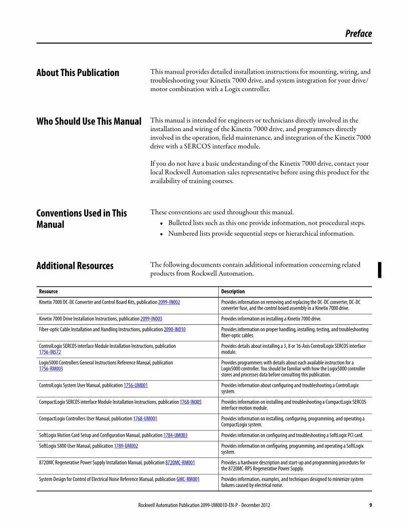
Additional Resources The following documents contain additional information concerning related products from Rockwell Automation.
Resource Description
Kinetix 7000 DC-DC Converter and Control Board Kits, publication 2099-IN002 Provides information on removing and replacing the DC-DC converter, DC-DC converter fuse, and the control board assembly in a Kinetix 7000 drive.
Kinetix 7000 Drive Installation Instructions, publication 2099-IN003 Provides information on installing a Kinetix 7000 drive.
Fiber-optic Cable Installation and Handling Instructions, publication 2090-IN010 Provides information on proper handling, installing, testing, and troubleshooting fiber-optic cables.
ControlLogix SERCOS interface Module Installation Instructions, publication 1756-IN572
Provides details about installing a 3, 8 or 16-Axis ControlLogix SERCOS interface module.
Logix5000 Controllers General Instructions Reference Manual, publication1756-RM003
Provides programmers with details about each available instruction for a Logix5000 controller. You should be familiar with how the Logix5000 controller stores and processes data before consulting this publication.
ControlLogix System User Manual, publication 1756-UM001 Provides information about configuring and troubleshooting a ControlLogix system.
CompactLogix SERCOS interface Module Installation Instructions, publication 1768-IN005 Provides information on installing and troubleshooting a CompactLogix SERCOS interface motion module.
CompactLogix Controllers User Manual, publication 1768-UM001 Provides information on installing, configuring, programming, and operating a CompactLogix system.
SoftLogix Motion Card Setup and Configuration Manual, publication 1784-UM003 Provides information on configuring and troubleshooting a SoftLogix PCI card.
SoftLogix 5800 User Manual, publication 1789-UM002 Provides information on configuring, programming, and operating a SoftLogix system.
8720MC Regenerative Power Supply Installation Manual, publication 8720MC-RM001 Provides a hardware description and start-up and programming procedures for the 8720MC-RPS Regenerative Power Supply.
System Design for Control of Electrical Noise Reference Manual, publication GMC-RM001 Provides information, examples, and techniques designed to minimize system failures caused by electrical noise.
Rockwell Automation Publication 2099-UM001D-EN-P - December 2012 9

Preface
You can view or download publications at http://literature.rockwellautomation.com. To order paper copies of technical documentation, contact your local Allen-Bradley distributor or Rockwell Automation® sales representative.
Kinetix Safe-off Feature Safety Reference Manual, publication GMC-RM002 Provides detailed installation instructions for wiring and troubleshooting a Kinetix 7000 safe-off drive.
Kinetix Motion Control Selection Guide, publication GMC-SG001 Provides descriptions and specifications for the 2099 product family including motors and accessories.
Kinetix 7000 Drive Systems Design Guide, publication GMC-RM007 The purpose of this publication is to assist you in identifying the drive system components and accessory items you’ll need for your Kinetix 7000 drive/motor combination.
Kinetix Servo Drives Specifications Technical Data, publication GMC-TD003 Provides catalog numbers and product specifications, including performance, environmental, certifications, load force, and dimension drawings for Allen-Bradley® servo drives.
Kinetix Motion Accessories Specifications Technical Data, publication GMC-TD004 Provides catalog numbers, product specifications, and dimensions for Allen-Bradley servo drive accessories.
Rockwell Automation Configuration and Selection Toolswebsite http://www.rockwellautomation.com/en/e-tools
Provides information and access to the Motion Analyzer application analysis software for drive/motor sizing.
Provides online product selection and system configuration tools, including AutoCAD (DXF) drawings.
Rockwell Automation Product Certification Website: http://www.rockwellautomation.com/products/certification/
Provides online access to declarations of conformity (DoC) currently available from Rockwell Automation.
Kinetix Accelerator Toolkit Quick Start, publication IASIMP-QS002 Provides examples of using a Logix controller to connect to multiple devices (servo drives, motors, and HMI) over the EtherNet/IP network in a Kinetix Integrated Motion application.
Kinetix Accelerator Toolkit Brochure, publication MOTION-BR004 Provides information about the Kinetix Accelerator Toolkit.
SERCOS and Analog Motion Configuration and Startup, publication MOTION-UM001
Provides information to create a motion coordinate system with SERCOS or analog motion modules.
Motion Coordinate System User Manual, publication MOTION-UM002 Provides, information on configuring and troubleshooting your ControlLogix, CompactLogix, and SoftLogix SERCOS interface modules.
Logix5000 Controllers Motion Instructions Reference Manual, publication MOTION-RM002 Provides programmers with details about the motion instructions that are available for a Logix5000 controller.
National Electrical Code, published by the National Fire Protection Association of Boston, MA Provides access to articles on wire sizes and types for grounding electrical equipment.
Safety Products, publication S117-CA001 Provides information on principle standards and implementation of safety products and catalogs available safety products.
Safety Guidelines for the Application, Installation, and Maintenance of Solid State Controls, publication SGI-IN001
Provides general guidelines for the application, installation, and maintenance of solid-state control in the form of individual devices or packaged assemblies incorporating solidstate components.
Understanding the Machinery Directive, publication SHB-900 Provides information on the CE marking process, with references to key European requirements and resources, and examples of safety component applications.
Allen-Bradley Industrial Automation Glossary, publication AG-7.1 A glossary of industrial automation terms and abbreviations.
Resource Description
10 Rockwell Automation Publication 2099-UM001D-EN-P - December 2012

Chapter 1
Start
Use this chapter to become familiar with the design and installation requirements for Kinetix 7000 drive systems.
Topic Page
About the Drive System 12
Typical Drive System Diagrams 13
Catalog Number Explanation 18
Agency Compliance 18
Rockwell Automation Publication 2099-UM001D-EN-P - December 2012 11

Chapter 1 Start
About the Drive System The Kinetix 7000 high-power servo drive is designed to provide a Kinetix Integrated Motion solution for applications with output power requirements in the range of 22…149 kW (40…248 A).
Table 1 - Kinetix 7000 Drive System Overview
Kinetix 7000 Component
Catalog Numbers Description
Servo Drive 2099-BMxx-S (1) The Kinetix 7000 servo drive with safe-off feature is available with 460V AC input power, or capable of operating with a shared DC bus.
Regenerative Power Supply
8720MC-RPS The 8720MC-RPS is a sinusoidal PWM converter that may serve as a regenerative power supply for one or more drives.
Logix Controller Platform
1756-L60M03SE module1756-MxxSE module1768-M04SE module1784-PM16SE PCI card
The SERCOS interface module/PCI card serves as a link between the ControlLogix/CompactLogix/SoftLogix platform and Kinetix 7000 drive system. The communication link uses the IEC 61491 SErial Real-time COmmunication System (SERCOS) protocol over a fiber-optic cable.
RSLogix 5000 Software 9324-RLD300ENE RSLogix 5000 provides support for programming, commissioning, and maintaining the Logix family of controllers.
Rotary Servo Motors MP-Series, HPK-Series, and RDD-Series
Compatible rotary servo motors include MP-Series (Bulletin MPL and MPM) 400V class motors, HPK-Series motors, and RDD-Series direct-drive motors.
Cables Motor Power, Feedback, and Brake cables
Bulletin 2090 motor power/brake and feedback cables are available with bayonet, threaded, and SpeedTec connectors. Power/brake cables have flying leads on the drive end and straight connectors that connect to servo motors. Feedback cables have flying leads that wire to low-profile connector kits on the drive end and straight connectors on the motor end.
Large power motors may require user power wiring to handle larger current requirements.
Communication Bulletin 2090 SERCOS fiber-optic cables are available as enclosure only, PVC, nylon, and glass with connectors at both ends.
AC Line Filters 2090-XXLF-TCxxxx Bulletin 2090-XXLF-TCxxxx three-phase AC line filters are required to meet CE and available for use in all Kinetix 7000 drive systems.
Line Interface Module 2094-BL50/75S, or 2094-XL75S-Cx
The line interface module (LIM) contains the circuit breakers, power supplies, and safety contactor required for Kinetix 7000 operation. Individual components can be purchased separately in place of the LIM.
External Shunt Modules
NA See External Shunt Modules on page 156 for active shunt solutions from Rockwell Automation Encompass Partners and intended for use with Kinetix 7000 drives.
(1) See the Kinetix Safe-off Feature Safety Reference Manual, publication GMC-RM002, for more information.
12 Rockwell Automation Publication 2099-UM001D-EN-P - December 2012

Start Chapter 1
Typical Drive System Diagrams
Typical Kinetix 7000 system installations include three-phase AC configurations, with and without the line interface module (LIM), and DC common bus configurations.
Figure 1 - Kinetix 7000 System Configuration with LIM and External Resistive Shunt
MAIN VACMAIN VAC
24V DCControl Power
External Shunt Module (optional component). SeeExternal Shunt Modules on page 156 for more
information.
2090-XXLF-TCxxxxAC Line Filter
2094-BL75SLine Interface Module(optional component)
460V ACThree-PhaseInput Power
RSLogix 5000 SoftwareInput
Logix 5000 Controller
Output
1756-MxxSE SERCOS Interface Module
2090-SCxxx-xSERCOS Fiber-Optic Ring
Commissioning
2099-BMxx-S Kinetix 7000 Drive
HPK-Series Motors, RDD-Series Direct Drive Motors, MPM-B165xx and MPM-B215xx, and MPL-B5xxx, MPL-B6xxx, MPL-B8xxx, and MPL-B9xxx (shown) Servo Motors
ControlLogix Chassis
Motor Power Cable
EncoderFeedbackCable
2090-K6CK-DxxxLow Profile Connector Kits forI/O, Motor Feedback,and Auxiliary Feedback
Safe-off,General Purpose I/O,
General Purpose RelayConnections
Rockwell Automation Publication 2099-UM001D-EN-P - December 2012 13

Chapter 1 Start
Figure 2 - Kinetix 7000 System Configuration without Line Interface Module (LIM)
1606-XLPower Supp ly
Input
Allen-Bradley1606-XLxxx24V DC
Control Power
2090-XXLF-TCxxxxAC Line Filter
Input Fusing
Three-PhaseInput Power
Input
Logix 5000Controller
Output
1756-MxxSESERCOS Interface Module
2090-SCxxx-xSERCOS Fiber-Optic Ring
Commissioning
2099-BMxx-S Kinetix 7000 Drive
ControlLogix Chassis
Motor Power Cable
EncoderFeedbackCable
2090-K6CK-DxxxLow Profile Connector Kits forI/O, Motor Feedback,and Auxiliary Feedback.
Control Power SupplyInput
InputContactor
Safe-off,General Purpose I/O,
General Purpose Relayconnections
External Shunt Module (optional component).See External Shunt Modules on page 156 for more
information.
HPK-Series Motors, RDD-Series Direct Drive Motors, MPM-B165xx and MPM-B215xx, and MPL-B5xxx, MPL-B6xxx, MPL-B8xxx, and MPL-B9xxx (shown) Servo Motors
RSLogix 5000 Software
14 Rockwell Automation Publication 2099-UM001D-EN-P - December 2012
Start Chapter 1
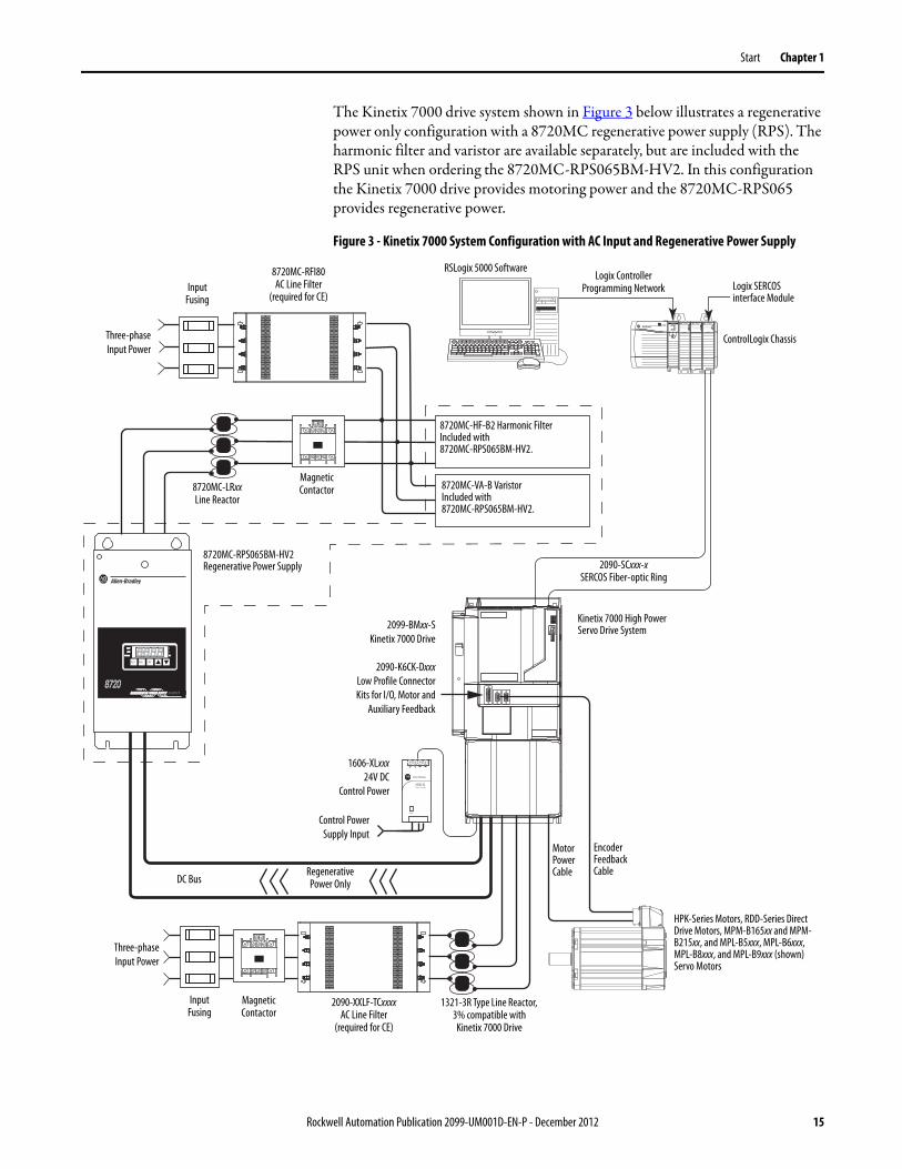
The Kinetix 7000 drive system shown in Figure 3 below illustrates a regenerative power only configuration with a 8720MC regenerative power supply (RPS). The harmonic filter and varistor are available separately, but are included with the RPS unit when ordering the 8720MC-RPS065BM-HV2. In this configuration the Kinetix 7000 drive provides motoring power and the 8720MC-RPS065 provides regenerative power.
Figure 3 - Kinetix 7000 System Configuration with AC Input and Regenerative Power Supply
1606-XLPower Supp ly
Input
Allen-Bradley
R E G E N E R A T IV E P O W E R S U P P LYREGENERATIVE POWER SUPPLY
87208720 MCMC
RST PRG ENT
READYREADY
FAULTFAULT
PROGRAMPROGRAM kWkW
V
A
EncoderFeedbackCable
2090-SCxxx-xSERCOS Fiber-optic Ring
DC Bus
8720MC-RPS065BM-HV2Regenerative Power Supply
8720MC-LRxxLine Reactor
Three-phaseInput Power
8720MC-VA-B VaristorIncluded with8720MC-RPS065BM-HV2.
8720MC-HF-B2 Harmonic FilterIncluded with8720MC-RPS065BM-HV2.
MagneticContactor
MotorPowerCable
1606-XLxxx24V DC
Control Power
8720MC-RFI80AC Line Filter
(required for CE)Input
Fusing
Three-phaseInput Power
MagneticContactor
InputFusing
1321-3R Type Line Reactor, 3% compatible with
Kinetix 7000 Drive
RegenerativePower Only
2099-BMxx-SKinetix 7000 Drive
2090-K6CK-DxxxLow Profile ConnectorKits for I/O, Motor and
Auxiliary Feedback
Control PowerSupply Input
Logix SERCOSinterface Module
ControlLogix Chassis
RSLogix 5000 SoftwareLogix Controller
Programming Network
Kinetix 7000 High Power Servo Drive System
2090-XXLF-TCxxxxAC Line Filter
(required for CE)
HPK-Series Motors, RDD-Series Direct Drive Motors, MPM-B165xx and MPM-B215xx, and MPL-B5xxx, MPL-B6xxx, MPL-B8xxx, and MPL-B9xxx (shown) Servo Motors
Rockwell Automation Publication 2099-UM001D-EN-P - December 2012 15

Chapter 1 Start
The Kinetix 7000 drive system shown in Figure 4 below illustrates a DC common bus configuration with two follower Kinetix 7000 (2099-BM11-S) drives and an 8720MC regenerative power supply (RPS). In full-line regenerative mode the 8720MC-RPS190 unit provides motoring and regenerative power.
Figure 4 - Kinetix 7000 System Configuration with AC Input and 8720MC-RPS190 with Full-line Regeneration
1606-XLPower Supply
Input
Allen-Bradley
REGENERATIVE POWER SUPPLYREGENERATIVE POWER SUPPLY
87208720 MCMC
RST PRG ENT
READYREADY
FAULTFAULT
PROGRAMPROGRAM kWkW
V
A
1606-XLPower Supply
Input
Allen-Bradley
REGENERATIVE POWER SUPPLY
87208720MCMC
RST PRG ENT
READYREADY
FAULFAULT
PROGRAMPROGRAM kWkW
V
A
2090-SCxxx-xSERCOS Fiber-optic Ring
DC Bus
Kinetix 7000 Drive2099-BM11-S
2090-K6CK-DxxxLow Profile ConnectorKits for I/O, Motor and
Auxiliary Feedback
8720MC-RPS190BMRegenerative Power Supply
Three-phaseInput Power
8720MC-EF190-VBEMC Line FilterThis unit includes an AC line filter (required for CE), magnetic contactor, harmonic filter, and varistor.
IMPORTANT The 8720MC-EF190-VB line filter unit and two 8720MC-LR10-100B line reactors are required when using the 8720MC-RPS190 regenerative power supply.
InputFusing
Full Regenerative
2099-BM11-SKinetix 7000 Drive
2090-K6CK-DxxxLow Profile ConnectorKits for I/O, Motor and
Auxiliary Feedback
1606-XLxxx24V DC
Control Power
1606-XLxxx24V DC
Control Power
EncoderFeedback Cable
MotorPower Cable
HPK-Series Motors
DC BusFusing
DC BusFusing
Control PowerSupply Input
Control PowerSupply Input
Logix SERCOSinterface ModuleRSLogix 5000 Software
Logix ControllerProgramming Network
8720MC-LR10-100BLine Reactor(two units in parallel)
EncoderFeedbackCableMotor
Power Cable
HPK-Series Motors, RDD-Series Direct Drive Motors, MPM-B165xx and MPM-B215xx, and MPL-B5xxx, MPL-B6xxx, MPL-B8xxx, and MPL-B9xxx (shown) Servo Motors
GroundFault
ProtectionFusing
16 Rockwell Automation Publication 2099-UM001D-EN-P - December 2012

Start Chapter 1
The Kinetix 7000 drive system shown in Figure 5 below illustrates a DC common bus configuration with two follower Kinetix 7000 drives and an 8720MC regenerative power supply (RPS). The harmonic filter and varistor are available separately, but are included when ordering the 8720MC-RPS065BM-HV2 RPS unit. In full-line regenerative mode the 8720MC-RPS065BM-HV2 unit provides motoring power and regenerative power. In common bus mode, you must calculate the total bus capacitance of your DC common bus system. This allows you to plan your panel layout and sufficiently size the 8720MC-RPS to precharge the entire system.
Figure 5 - Kinetix 7000 System Configuration with DC Input from 8720MC-RPS065 Providing Full-line Regeneration
1606-XLPower Supp ly
Input
Allen-Bradley
R E G E N E R A T IV E P O W E R S U P P LYREGENERATIVE POWER SUPPLY
87208720 MCMC
RST PRG ENT
READYREADY
FAULTFAULT
PROGRAMPROGRAM kWkW
V
A
1606-XLPower Supp ly
Input
Allen-Bradley
1606-XLxxx24V DC
Control Power
8720MC-RF180AC Line Filter
Input Fusing
Three-PhaseInput Power
RSLogix 5000 Software
Input
Logix 5000Controller
Output
1756-MxxSE SERCOS Interface Module
2090-SCxxx-xSERCOS Fiber-Optic Ring
Commissioning
2099-BMxx-SKinetix 7000 Drive
ControlLogix Chassis
Motor Power Cable
Encoder FeedbackCable
2090-K6CK-DxxxLow Profile Connector Kits for
I/O, Motor Feedback,and Auxiliary Feedback.
Control PowerSupply Input
(To retain logic controlwhen main DC power is
removed.)
Magnetic Contactor
1606-XLxxx24V DC
Control Power
HPK-Series Motors
Motor Power Cable Encoder Feedback Cable
DC BusFusing
DC BusFusing
Full Regenerative DC Bus
Control PowerSupply Input
(To retain logiccontrol when
main DC poweris removed.)
2099-BMxx-SKinetix 7000 Drive
2090-K6CK-DxxxLow Profile Connector Kits for
I/O, Motor Feedback,and Auxiliary Feedback
GroundFault
ProtectionFusing
8720MC-LRxxLine Reactor
8720MC-RPS065BM-HV2Regenerative Power Supply
Harmonic Filter (included with
8720MC-RPS065BM-HV2Regenerative Power Supply)
Varistor (included with
8720MC-RPS065BM-HV2Regenerative Power Supply)
HPK-Series Motors, RDD-Series Direct Drive Motors, MPM-B165xx and MPM-B215xx, and MPL-B5xxx, MPL-B6xxx, MPL-B8xxx, and MPL-B9xxx (shown) Servo Motors
Rockwell Automation Publication 2099-UM001D-EN-P - December 2012 17

Chapter 1 Start
Catalog Number Explanation Kinetix 7000 drive catalog numbers and descriptions are listed in the table below.
Agency Compliance If this product is installed within the European Union or EEC regions and has the CE mark, the following regulations apply.
For more information on electrical noise reduction, see the System Design for Control of Electrical Noise Reference Manual, publication GMC-RM001.
Kinetix 7000 Drive Cat. No.
Kinetix 7000, 460V, 22 kW, 40 A continuous output 2099-BM06-S
Kinetix 7000, 460V, 30 kW, 52 A continuous output 2099-BM07-S
Kinetix 7000, 460V, 37 kW, 65 A continuous output 2099-BM08-S
Kinetix 7000, 460V, 56 kW, 96 A continuous output 2099-BM09-S
Kinetix 7000, 460V, 75 kW, 125 A continuous output 2099-BM10-S
Kinetix 7000, 460V, 112 kW, 180 A continuous output 2099-BM11-S
Kinetix 7000, 460V, 149 kW, 248 A continuous output 2099-BM12-S
ATTENTION: Meeting CE requires a grounded system, and the method of grounding the AC line filter and drive must match. Failure to do this renders the filter ineffective and may cause damage to the filter.For grounding examples, see Grounded Power Configurations on page 75.
18 Rockwell Automation Publication 2099-UM001D-EN-P - December 2012
Start Chapter 1
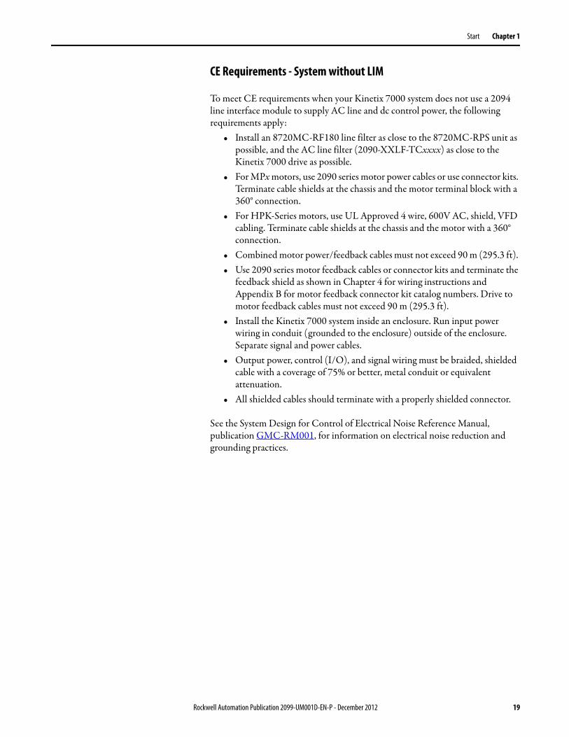
CE Requirements - System without LIM
To meet CE requirements when your Kinetix 7000 system does not use a 2094 line interface module to supply AC line and dc control power, the following requirements apply:
• Install an 8720MC-RF180 line filter as close to the 8720MC-RPS unit as possible, and the AC line filter (2090-XXLF-TCxxxx) as close to the Kinetix 7000 drive as possible.
• For MPx motors, use 2090 series motor power cables or use connector kits. Terminate cable shields at the chassis and the motor terminal block with a 360° connection.
• For HPK-Series motors, use UL Approved 4 wire, 600V AC, shield, VFD cabling. Terminate cable shields at the chassis and the motor with a 360° connection.
• Combined motor power/feedback cables must not exceed 90 m (295.3 ft). • Use 2090 series motor feedback cables or connector kits and terminate the
feedback shield as shown in Chapter 4 for wiring instructions and Appendix B for motor feedback connector kit catalog numbers. Drive to motor feedback cables must not exceed 90 m (295.3 ft).
• Install the Kinetix 7000 system inside an enclosure. Run input power wiring in conduit (grounded to the enclosure) outside of the enclosure. Separate signal and power cables.
• Output power, control (I/O), and signal wiring must be braided, shielded cable with a coverage of 75% or better, metal conduit or equivalent attenuation.
• All shielded cables should terminate with a properly shielded connector.
See the System Design for Control of Electrical Noise Reference Manual, publication GMC-RM001, for information on electrical noise reduction and grounding practices.
Rockwell Automation Publication 2099-UM001D-EN-P - December 2012 19

Chapter 1 Start
CE Requirements - System with LIM
To meet CE requirements when your Kinetix 7000 system includes the line interface module (LIM), follow all the requirements as stated in CE Requirements - System without LIM on page 19 and these additional requirements that also apply to the AC line filter:
• Install the LIM, 2094-XL75S-Cx or 2094-BL50/75S, and line filter (2090-XXLF-TCxxx) as close to the Kinetix 7000 drive as possible.
CE Requirements - System with DC Common Bus through 8720MC-RPS
To meet CE requirements when your Kinetix 7000 system includes a common DC bus with an 8720MC-RPS, follow all the requirements as stated in the CE Requirements - System without LIM on page 19, the recommended installation and wiring in the 8720MC Regenerative Power Supply Reference Manual, publication 8720MC-RM001, and these additional requirements:
• Install a three-phase line filter on the AC input power line of the RPS as indicated in Interconnect Diagrams beginning on page 161.
• Install a single-phase line filter when attaching an AC line input to the RPS MC1/2 circuit as indicated in the Interconnect Diagrams beginning on page 161.
IMPORTANT The full rated current on the AC input line should not exceed that of the line interface module.Catalog numbers 2094-XL75S-Cx or 2094-BL50S for 2099-BM06-S and 2099-BM07-S Kinetix 7000 drives, or 2094-BL75S for 2099-BM08-S Kinetix 7000 drives.
IMPORTANT CE requires use of a grounded secondary or source with a 2099-BMxx-S drive.Never use a LIM in an ungrounded input, due to the potential for high line-to-neutral voltages damaging components within the line filter.
20 Rockwell Automation Publication 2099-UM001D-EN-P - December 2012
Chapter 2
Install the Kinetix 7000 Drive System
This chapter describes system installation guidelines in preparation for mounting your Kinetix 7000 drive components.
Topic Page
System Design Guidelines 22
Minimizing Electrical Noise 28
Mount the Kinetix 7000 Drive 39
ATTENTION: Plan the installation of your system so that you can perform all cutting, drilling, tapping, and welding with the system removed from the enclosure. Because the system is of the open type construction, be careful to keep any metal debris from falling into it. Metal debris or other foreign matter can become lodged in the circuitry, which can result in damage to components.
Rockwell Automation Publication 2099-UM001D-EN-P - December 2012 21

Chapter 2 Install the Kinetix 7000 Drive System
System Design Guidelines To design your enclosure and plan where to mount the system components on the panel, use this section and the information in the Kinetix Servo Drives Specifications Technical Data, publication GMC-TD003.
For online product selection and system configuration tools, including AutoCAD (DXF) drawings of the product, go to: http://www.rockwellautomation.com/en/e-tools/.
System Mounting Requirements
Follow these system mounting requirements.• To comply with UL and CE requirements, the Kinetix 7000 drive system
must be enclosed in a grounded conductive enclosure offering protection as defined in standard EN 60529 (IEC 529) to NEMA/UL Type IP2X such that they are not accessible to an operator or unskilled person. A NEMA/UL Type 4X enclosure exceeds these requirements providing protection to IP66.
• The panel you install inside the enclosure for mounting your system components must be on a flat, rigid, vertical surface that won’t be subjected to shock, vibration, moisture, oil mist, dust, or corrosive vapors (as specified in Environmental Specifications on page 154).
• Size the drive enclosure so as not to exceed the maximum ambient temperature rating. Consider heat dissipation specifications for all drive components.
• Segregate input power wiring and motor power cables from control wiring and motor feedback cables. Use shielded cable for power wiring and provide a grounded 360° clamp termination.
• Use high-frequency (HF) bonding techniques to connect the modules, enclosure, machine frame, and motor housing, and to provide a low-impedance return path for HF energy and reduce electrical noise.
See the System Design for Control of Electrical Noise Reference Manual, publication GMC-RM001, to better understand the concept of electrical noise reduction.
Transformer Selection
The Kinetix 7000 drive does not require an isolation transformer for three-phase input power. However, a transformer may be required to match the voltage requirements of the controller to the available service.
22 Rockwell Automation Publication 2099-UM001D-EN-P - December 2012

Install the Kinetix 7000 Drive System Chapter 2
To size a transformer for the AC power inputs to devices peripheral to the Kinetix 7000 drive, refer to the manufacturer continuous output power specification.
Circuit Breaker/Fuse Selection
The Kinetix 7000 drive uses internal solid-state motor short-circuit protection and, when protected by suitable branch circuit protection, are rated for use on a circuit capable of delivering up to 200,000 A. Fuses or circuit breakers, with adequate withstand and interrupt ratings, as defined in NEC or applicable local codes, are permitted.
The 2094-BL50 and 2094-BL75S LIMs contain supplementary protection devices, but require a customer-supplied external line filter. See the Line Interface Module Installation Instructions, publication 2094-IN005, for power specifications and more information on using the LIM module.
The Bulletin 140M motor protection circuit breakers are another acceptable means of protection. As with fuses and circuit breakers, you must make sure that the selected components are properly coordinated and meet applicable codes including any requirements for branch circuit protection. When applying the 140M product, evaluation of the short circuit available current is critical and must be kept below the short circuit rating of the 140M product.
In most cases, fuses selected to match the drive input current rating will meet the NEC requirements and provide the full drive capabilities. Dual element, time delay (slow acting) fuses should be used to avoid nuisance trips during the inrush current of power initialization.
See Circuit Breaker/Fuse Specifications on page 151 for recommended circuit breakers and fuses.
See Power Specifications on page 150 for input current and inrush current specifications for your Kinetix 7000.
IMPORTANT If using an autotransformer, make sure that the phase to neutral/ground voltages do not exceed the input voltage ratings of the drive.
IMPORTANT Use a form factor of 1.5 for three-phase power (where form factor is used to compensate for transformer, drive module and motor losses, and to account for utilization in the intermittent operating area of the torque speed curve).For example: using a secondary of 480 VAC and a 2099-BM06-S with a rated power output = 22 kW continuous:22 * 1.5 = 33 kVA transformer
Rockwell Automation Publication 2099-UM001D-EN-P - December 2012 23

Chapter 2 Install the Kinetix 7000 Drive System
Enclosure Selection
To assist you in sizing an enclosure, the following example is provided. The example system consists of the following components.
• 2-axis Kinetix 7000 servo drive system• ControlLogix chassis and modules
Size the Kinetix 7000 servo drive using Motion Analyzer software, version 4.2 or later, and use the results to predict the amount of heat dissipated into the enclosure. You will also need heat dissipation data from other equipment inside the enclosure (such as ControlLogix). Once the total amount of heat dissipation (in watts) is known, the minimum enclosure size can be calculated. It is recommended that you also contact the enclosure manufacturer for the best enclosure fit, including possible cooling methods to help reduce enclosure size.
Using Motion Analyzer to Determine Heat Dissipation
To obtain Motion Analyzer software, go to:http://ab.rockwellautomation.com/Motion-Control/Motion-Analyzer-Software
Complete the Motion Analyzer Axis View data to find an acceptable Kinetix 7000 drive and motor solution to meet the application needs. In the Axis View Solutions window find the Drive Capacity value. In this example, the2099-BM11-S Drive Capacity characteristic can be used for the estimation of the Rated Power Output used for the percentage of watts dissipated.
24 Rockwell Automation Publication 2099-UM001D-EN-P - December 2012

Install the Kinetix 7000 Drive System Chapter 2
Table 2 - Kinetix 7000 System Heat Dissipation Example
Table 3 - ControlLogix Heat Dissipation Example
Figure 6 - ControlLogix Real Power
For backplane power loading requirements of other ControlLogix power supplies, see the ControlLogix Selection Guide, publication 1756-SG001.
Enclosure Component
Description Loading (1)
(Motion Analyzer)
(1) Loading determined using Motion Analyzer software.
Heat Dissipation (2)
Watts
(2) To determine heat dissipation specifications for the Kinetix 7000 drive, see Power Dissipation Specifications on page 152.
2099-BM08-S Kinetix 7000 Servo Drive 50% 452
2099-BM11-S Kinetix 7000 Servo Drive 50% 1275
Total Wattage of Kinetix 7000 system 1727
Enclosure Component
Description Backplane Power Load (1) Watts
(1) For ControlLogix module specifications, see the ControlLogix Selection Guide, publication 1756-SG001.
Heat Dissipation (1)
Watts
1756-M08SE 8-axis SERCOS interface module 3.2 0.0
1756-L5563 L63 ControlLogix processor 4.5 0.0
1756-IB16D 16-point input module 0.84 5.8
1756-OB16D 16-point output module 4.64 3.3
1756-ENxTx EtherNet/IP communication module 4.0 0.0
Backplane total 17.18 (2)
(2) Real power heat dissipation is determined by applying the backplane power load (17.18 W) to the graph below.
N/A
1756-PB72 24V DC ControlLogix power supply N/A 25.0 (2)
1756-A7 7-slot mounting chassis N/A N/A
Total ControlLogix system wattage 34.1
75604530150
0 20 40 60 80 100
BackplanePower Load
(Watts)
Real Power (Watts)
1756-P B721756-P B75DC
Rockwell Automation Publication 2099-UM001D-EN-P - December 2012 25

Chapter 2 Install the Kinetix 7000 Drive System
In this example, the amount of power dissipated inside the cabinet is the sum of the Kinetix 7000 drive (2099-BM08-S and 2099-BM11-S) system value (1727 W) and the ControlLogix value (34.1 W) for a total of 1761 W.
With no active method of heat dissipation (such as fans or air conditioning) either of the following approximate equations can be used.
The maximum ambient rating of the Kinetix 7000 drive is 50 °C (122 °F) and if the maximum environmental temperature is 30 °C (86 °F) then Q=1761 and T=20 in the equation below.
In this example, the enclosure must have an exterior surface of 19.2 m2. If any portion of the enclosure is not able to transfer heat, it should not be included in the calculation. For instance, if an externally-mounted shunt system is used with the Kinetix 7000 system, it should not be included in the equation.
The minimum enclosure size must take into account the physical size and minimum clearance requirements of the two Kinetix 7000 drives and the additional ControlLogix and other devices required to meet the application needs.
If the enclosure size is considerably larger than what is necessary to house the system components, it may be more efficient to provide a means of cooling in a smaller enclosure. Contact your enclosure manufacturer for options available to cool your enclosure.
Metric Standard English
Where T is temperature difference between inside air and outside ambient (°C), Q is heat generated in enclosure (Watts), and A is enclosure surface area (m2). The exterior surface of all six sides of an enclosure is calculated as
Where T is temperature difference between inside air and outside ambient (°F), Q is heat generated in enclosure (Watts), and A is enclosure surface area (ft²). The exterior surface of all six sides of an enclosure is calculated as
A = 2dw + 2dh + 2wh A = (2dw + 2dh + 2wh) / 144
Where d (depth), w (width), and h (height) are in meters. Where d (depth), w (width), and h (height) are in inches.
A 0.38Q1.8T 1.1–--------------------------= A 4.08Q
T 1.1–------------------=
A = 0.38 (1761)1.8 (20) - 1.1
A = 19.2 m2
26 Rockwell Automation Publication 2099-UM001D-EN-P - December 2012

Install the Kinetix 7000 Drive System Chapter 2
Minimum Clearance Requirements
This section provides information to assist you in sizing your cabinet and positioning your Kinetix 7000 system components.
Figure 7 - Minimum Clearance Requirements
See page 152 for power dissipation specifications.
IMPORTANT Mount the module in an upright position as shown. Do not mount the module on its side.
50.8 mm (2.0 in.) clearance right of module is required
Minimum cabinet depth = 300 mm (11.8 in.)
Cable bend radius requires a minimum of60 mm (2.4 in.) from the front panel connections.
101.6 mm (4.0 in.) clearance for airflow and installation
50.8 mm (2.0 in.) clearance leftof module is required
101.6 mm (4.0 in.) clearance for airflow and installation
Rockwell Automation Publication 2099-UM001D-EN-P - December 2012 27

Chapter 2 Install the Kinetix 7000 Drive System
Minimizing Electrical Noise This section outlines best practices that minimize the possibility of noise-related failures as they apply specifically to Kinetix 7000 drive installations. For more information on the concept of high-frequency (HF) bonding, the ground plane principle, and electrical noise reduction, see the System Design for Control of Electrical Noise Reference Manual, publication GMC-RM001.
Bonding Modules
Bonding is the practice of connecting metal chassis, assemblies, frames, shields, and enclosures to reduce the effects of electromagnetic interference (EMI).
Unless specified, most paints are not conductive and act as insulators. To achieve a good bond between the drive and subpanel, surfaces need to be unpainted or plated. Bonding metal surfaces creates a low-impedance return path for high-frequency energy.
Improper bonding blocks the direct return path and routes high-frequency energy to elsewhere in the cabinet. Excessive high-frequency energy can effect the operation of other microprocessor controlled equipment.
The illustrations that follow show details of recommended bonding practices for painted panels, enclosures, and mounting brackets.
IMPORTANT To improve the bond between the drive and subpanel, construct your subpanel out of zinc plated (unpainted) steel.
28 Rockwell Automation Publication 2099-UM001D-EN-P - December 2012

Install the Kinetix 7000 Drive System Chapter 2
Figure 8 - Recommended Bonding Practices for Painted Panels
Stud-mounting the Subpanelto the Enclosure Back Wall
Stud-mounting a Ground Busor Chassis to the Subpanel
Subpanel Welded Stud
Scrape Paint
Flat Washer
If the mounting bracket is coated with a non-conductive material (anodized, painted, etc.), scrape the material around the mounting hole.
Star Washer
NutNut
Flat Washer
Mounting Bracket orGround Bus
Use a wire brush to remove paint from threads to maximize ground connection.
Back Wall of Enclosure
Welded Stud
Subpanel
Star Washer
Use plated panels or scrape paint off front of panel.
Subpanel
Nut
Nut
Star Washer
Flat Washer
Star Washer
Star WasherScrape paint on both sides of panel and use star washers.
Tapped Hole
Bolt
Flat Washer
Ground Bus orMounting Bracket
If the mounting bracket is coated with a non-conductive material (anodized, or painted for example), scrape the material around the mounting hole.
Bolt-mounting a Ground Bus or Chassis to the Back-panel
Rockwell Automation Publication 2099-UM001D-EN-P - December 2012 29

Chapter 2 Install the Kinetix 7000 Drive System
Bonding Multiple Subpanels
Bonding multiple subpanels creates a common low impedance exit path for the high frequency energy inside the cabinet. Subpanels that are not bonded together may not share a common low impedance path. This difference in impedance may affect networks and other devices that span multiple panels.
Figure 9 - Multiple Subpanels and Cabinet Recommendations
Establish Noise Zones
When designing a panel for a Kinetix 7000 system, observe the following guidelines with additional attention to zone locations.
Bond the top and bottom of each subpanel to the cabinet using 25.4 mm (1.0 in.) by 6.35 mm (0.25 in.) wire braid.
Scrape the paint around each fastener to maximize metal to metal contact.
Cabinet ground bus bonded to the subpanel.
30 Rockwell Automation Publication 2099-UM001D-EN-P - December 2012

Install the Kinetix 7000 Drive System Chapter 2
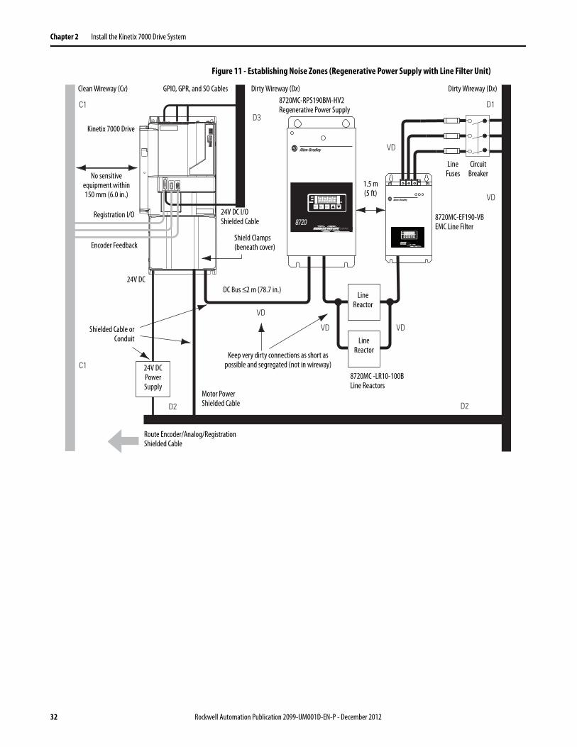
Noise Zones when Using Regenerative Power Supplies (with/without a Line Filter Unit)
Observe the following guidelines when laying out a Kinetix 7000 system panel if a regenerative power supply (8720-RPSxxxxx) is used (see Figure 10), and if a regenerative power supply and line filter unit are used (see Figure 11 on page 32).
• Mount the regenerative power supply to the right of the drive.• The clean zone (C) is beneath and left of the Kinetix 7000 drive. This zone
includes the motor feedback, auxiliary feedback and registration signals from the IOD connector (grey wireway).
• The dirty zone (D) is to the right of the Kinetix 7000 drive. This zone includes the motor power, GPIO, GPR, SO, and IOD connections (black wireway).
• The very dirty zone (VD) includes both the 8720MC-RPS DC output to the Kinetix 7000 drive and the fuses, contactors, circuit breakers, and AC line input to the EMC line filter to the right of the 8720MC-RPS. Shielded cable is required only if the very dirty cables enter a wireway.
• The SERCOS fiber-optic cables are immune to electrical noise.
Figure 10 - Establishing Noise Zones (Regenerative Power Supply)
C1
C1
D3
D2
R E G E NE R AT IV E P O WE R S U P P LYREGENERATIVE POWER SUPPLY
87208720 MCMC
RST PRG ENT
READYREADY
FAULTFAULT
PROGRAMPROGRAM kWkW
V
A
VD
VD
D2
D1
Route Encoder/Analog/RegistrationShielded Cable
Shielded Cable orConduit
Clean Wireway (Cx)
No sensitive equipment within 150 mm (6.0 in.)
Dirty Wireway (Dx)
Shield Clamps(beneath cover)
Motor PowerShielded Cable
8720MCLine Reactor
Registration I/O
24V DC
Kinetix 7000 Drive
24V DC I/OShielded Cable
GPIO, GPR, and SO Cables Dirty Wireway (Dx)
24V DC Power Supply
DC Bus ≤2 m (78.7 in.)
Keep very dirty (VD) connections as short as possible and segregated (not in wireway)
ACLineFilter
MagneticContactor
LineFuses
CircuitBreaker
8720MC-RPS065BM-HV2Regenerative Power Supply
HarmonicFilter
Varistor
Encoder Feedback
Rockwell Automation Publication 2099-UM001D-EN-P - December 2012 31
Chapter 2 Install the Kinetix 7000 Drive System
Figure 11 - Establishing Noise Zones (Regenerative Power Supply with Line Filter Unit)
C1
C1
D3
D2
R E G E NE R AT IV E P O WE R S U P P LYREGENERATIVE POWER SUPPLY
87208720 MCMC
RST PRG ENT
READYREADY
FAULTFAULT
PROGRAMPROGRAM kWkW
V
A
VD
VD
D2
D1
VD
REGENERATIVE POWER SUPPLY
87208720MCMC
RST PRG ENT
READYREADY
FAULFAULT
PROGRAMPROGRAM kWkW
V
A
VD
VD
Route Encoder/Analog/RegistrationShielded Cable
Shielded Cable orConduit
Clean Wireway (Cx)
No sensitive equipment within 150 mm (6.0 in.)
Dirty Wireway (Dx)
Shield Clamps(beneath cover)
Motor PowerShielded Cable
LineReactor
Registration I/O
24V DC
Kinetix 7000 Drive
24V DC I/OShielded Cable
GPIO, GPR, and SO Cables Dirty Wireway (Dx)
24V DC Power Supply
Keep very dirty connections as short as possible and segregated (not in wireway)
LineFuses
CircuitBreaker
8720MC-RPS190BM-HV2Regenerative Power Supply
Encoder Feedback
DC Bus ≤2 m (78.7 in.)
LineReactor
8720MC -LR10-100BLine Reactors
8720MC-EF190-VBEMC Line Filter
1.5 m(5 ft)
32 Rockwell Automation Publication 2099-UM001D-EN-P - December 2012

Install the Kinetix 7000 Drive System Chapter 2
AC Power Noise Zones
Observe the following guidelines when laying out a Kinetix 7000 system panel, if an AC power supply is used (and regenerative power will not be used).
• The clean zone (C) is beneath and left of the Kinetix 7000 drive. This zone includes the motor feedback, auxiliary feedback and registration signals from the IOD connector (grey wireway).
• One dirty zone (D) is beneath and right of the Kinetix 7000 drive. This zone includes fuses, contactors, circuit breakers, AC line input to the EMC line filter (black wireway).
• The very dirty zone (VD) is limited to where the AC line output exits from the EMC line filter and connects to the Kinetix 7000 drive. Shielded cable is required only if the very dirty cables enter a wireway.
• The SERCOS fiber-optic cables are immune to electrical noise.
Figure 12 - Establishing Noise Zones (AC Power)
(1) When space does not permit the 150 mm (6.0 in.) segregation, use a grounded steel shield instead. For examples, see the System Design for Control of electrical Noise Reference Manual, publication GMC-RM001.
CC D
VDD
Route Encoder/Analog/RegistrationShielded Cable
Shielded Cable or Conduit
Clean Wireway (C)
No sensitive equipment within 150
mm (6.0 in.) (1)
Shield Clamps(beneath cover)
Motor Power Shielded Cable
Kinetix 7000 Drive
24V DC I/O Shielded Cable
Dirty Wireway (D)
Keep very dirty connections as short aspossible and segregated (not in wireway)
AC Line Filter
Contactor
Line Fuses Circuit
Breaker
Shielded Clamps
Rockwell Automation Publication 2099-UM001D-EN-P - December 2012 33
Chapter 2 Install the Kinetix 7000 Drive System
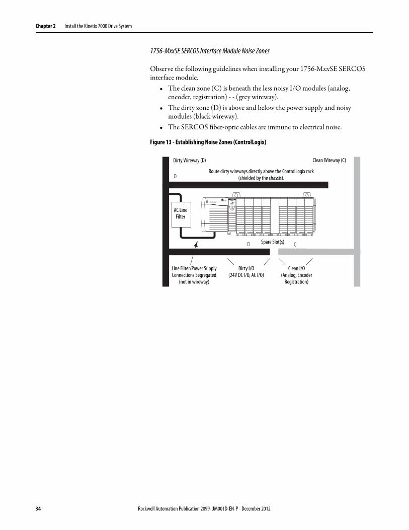
1756-MxxSE SERCOS Interface Module Noise Zones
Observe the following guidelines when installing your 1756-MxxSE SERCOS interface module.
• The clean zone (C) is beneath the less noisy I/O modules (analog, encoder, registration) - - (grey wireway).
• The dirty zone (D) is above and below the power supply and noisy modules (black wireway).
• The SERCOS fiber-optic cables are immune to electrical noise.
Figure 13 - Establishing Noise Zones (ControlLogix)
D
D
C
AC LineFilter
Spare Slot(s)
Dirty Wireway (D) Clean Wireway (C)
Route dirty wireways directly above the ControlLogix rack(shielded by the chassis).
Line Filter/Power Supply Connections Segregated
(not in wireway)
Dirty I/O(24V DC I/O, AC I/O)
Clean I/O(Analog, Encoder
Registration)
34 Rockwell Automation Publication 2099-UM001D-EN-P - December 2012

Install the Kinetix 7000 Drive System Chapter 2
Cable Categories for Kinetix 7000 Systems
The table below indicates the zoning requirements of input power cables connecting to the Kinetix 7000 drive.
Table 4 - Kinetix 7000 Drive
The table below indicates the zoning requirements of power and control cables connecting to the Kinetix 7000 system.
Table 5 - Kinetix 7000 System
Wire/Cable Connector Zone Method
Very Dirty
Dirty Clean Ferrite Sleeve
Shielded Cable
Control Power CP X
DC-/DC+
PTB
X
L1, L2, L3 (shielded cable) X X
L1, L2, L3 (unshielded cable) X
DPI DPI X X
Wire/Cable Connector Zone Method
Very Dirty
Dirty Clean Ferrite Sleeve
Shielded Cable
U, V, W (Motor Power) MP X X
GPR+, GPR- (Motor Brake) GPR X
24V DC (PWR), COM, filtered GPIO, GPR
X
24V DC (PWR), COM, unfiltered X
24V DC (PWR), COM, safety enable, and feedback signals for safe-off feature
SO X
Motor Feedback MF X X
Auxiliary Feedback AF X X
Registration and Analog OutputsIOD
X X
Others X
Fiber-optic Rx and Tx No Restrictions
Rockwell Automation Publication 2099-UM001D-EN-P - December 2012 35

Chapter 2 Install the Kinetix 7000 Drive System
Table 6 - Line Interface Module
Table 7 - External Shunt Resistor Kit
Noise Reduction Guidelines for Drive Accessories
When mounting an AC (EMC) line filter or external shunt resistor refer to the sections below for guidelines designed to reduce system failures caused by excessive electrical noise.
AC Line Filters
Observe the following guidelines when mounting your AC (EMC) line filter.
See the Establishing Noise Zones (AC Power) on page 33 for an example.
• Mount the ac line filter on the same panel as the Kinetix 7000 drive and as close to the power input as possible.
• Good HF bonding to the panel is critical.
For painted panels, refer to the examples on page 29.• Segregate input and output wiring as far as possible.
Wire/Cable Connector Zone Method
Very Dirty
Dirty Clean Ferrite Sleeve
Shielded Cable
VAC line (main input) IPL X
230V AC input APL X
VAC load (shielded option)OPL
X X
VAC load (unshielded option) X
Control power output CPL X
MBRK PWR, MBRK COM P1L/PSL X
Status I/O IOL X
Auxiliary 230V AC P2L X
Wire/Cable Connector Zone Method
Very Dirty
Dirty Clean Ferrite Sleeve
Shielded Cable
COL, DC+ (shielded option)RC
X X
COL, DC+ (unshielded option) X
Thermal switch TS X X
Fan (if present) N/A X
IMPORTANT CE test certification applies only to ac line filter and single drive. Sharing a line filter with multiple drives may perform satisfactorily, but the user takes legal responsibility.
36 Rockwell Automation Publication 2099-UM001D-EN-P - December 2012

Install the Kinetix 7000 Drive System Chapter 2
Shunt Resistor
Observe the following guidelines when mounting your external shunt resistor outside the enclosure.
• Mount circuit components and wiring in the very dirty zone or in an external shielded enclosure. Run shunt power and fan wiring inside metal conduit to minimize the effects of EMI and RFI.
• Mount resistors (other than metal-clad) in a shielded and ventilated enclosure outside the cabinet
• Keep unshielded wiring as short as possible. Keep shunt wiring as flat to the cabinet as possible.
• Route thermal switch and fan wires separate from shunt power.
Figure 14 - External Shunt Resistor Outside the Enclosure
C1
C1
VD
D3
D2
D1
VD
VD
D1
D2
Kinetix 7000 drive
Clean Wireway Dirty Wireway
No sensitive equipment within 150 mm (6.0 in.)
Motor Power Cables
Very dirty connections segregated (not in wireway)
Route 24V DC I/OShielded Cable
Route Encoder/Analog/Registration
Shielded Cables
Customer-suppliedmetal enclosure
Minimum of 150 mm (6.0 in.) of clearanceon all sides of the shunt module
Enclosure
Shunt Power Wiring Methods:Twisted pair in conduit (1st choice)Shielded twisted pair (2nd choice)Twisted pair, 2 twists per foot min. (3rd choice)
Metal conduit(where requiredby local code)
I/O and Feedback Cables
Rockwell Automation Publication 2099-UM001D-EN-P - December 2012 37

Chapter 2 Install the Kinetix 7000 Drive System
When mounting your shunt module inside the enclosure, follow these additional guidelines.
• Metal-clad modules can be mounted anywhere in the dirty zone, but as close to the Kinetix 7000 system as possible.
• Shunt power wires can be run with motor power cables.• Keep unshielded wiring as short as possible. Keep shunt wiring as flat to
the cabinet as possible.• Separate shunt power cables from other sensitive, low voltage signal cables.• The shunt module watts dissipation must be included in the Kinetix 7000
system heat dissipation calculation for selecting an enclosure.
Figure 15 - External Shunt Resistor Inside the Enclosure
Motor Brake and Thermal Switch
The thermal switch and brake are mounted inside the motor, but how you connect to the axis module depends on the motor series.
See Wire Motor Output Power on page 92 for wiring guidelines specific to your drive/motor combination, and to Interconnect Diagram Notes on page 162 for the interconnect diagram of your drive/motor combination.
C1
C1
VD
D3
D2
D1
VD
VD
D1
D2
Kinetix 7000
Dirty WirewayClean Wireway
No sensitive equipment within150 mm (6.0 in.)
Motor Power Cables
Very dirty connections segregated (not in wireway)Route 24V DC I/O
Shielded Cable
Route Encoder/Analog/RegistrationShielded Cables
Observe minimum clearance requirements for shunt module spacing.
Enclosure
Shunt Module
Shunt Wiring Methods:Twisted pair in conduit (1st choice).Shielded twisted pair (2nd choice).Twisted pair, 2 twists per foot min.(3rd choice).
I/O and Feedback Cables
AC Line Filter
38 Rockwell Automation Publication 2099-UM001D-EN-P - December 2012

Install the Kinetix 7000 Drive System Chapter 2
Mount the Kinetix 7000 Drive
Follow these steps to install your Kinetix 7000 drive.
1. Layout and mark the position for your drive in the enclosure.
Follow the Kinetix 7000 mounting information provided in Figure 16 on page 40. Clearance requirements on page 27 must also be followed.
2. Attach the drive to the cabinet.
The recommended mounting bolts are listed in the table on page 40. Follow the recommended high-frequency (HF) bonding techniques as shown in Bonding Modules beginning on page 28.
Follow the lifting instructions found in the Kinetix 7000 High Power Servo Drive Installation Instructions, publication 2099-IN003.
3. Tighten all mounting fasteners.
SHOCK HAZARD: To avoid hazard of electrical shock, perform all mounting and wiring of the drive prior to applying power. Once power is applied, connector terminals may have voltage present even when not in use.
ATTENTION: Plan the installation of your system so that you can perform all cutting, drilling, tapping, and welding with the system removed from the enclosure. Because the system is of the open type construction, be careful to keep any metal debris from falling into it. Metal debris or other foreign matter can become lodged in the circuitry, which can result in damage to components.
Rockwell Automation Publication 2099-UM001D-EN-P - December 2012 39

Chapter 2 Install the Kinetix 7000 Drive System
Figure 16 - Kinetix 7000 Approximate Mounting Dimensions
B
C
M1
M2 M3
A
2099-BM07 shown
Kinetix 7000 DriveCat. No.
Dimensions in mm (in.)
Mounting Screw SizeA B C M1 M2 M3
2099-BM06-S2099-BM07-S2099-BM08-S
517.5 (20.37) 254.12 (10.0) 224.3 (8.83) 495.0 (19.49) 192.0 (7.56) 15.3 (0.60) M6 (0.25)
2099-BM09-S 644.5 (25.37) 331.9 (13.07) 286.7 (11.29) 625.0 (24.61) 225.0 (8.86) 37.5 (1.48) M6 (0.25)
2099-BM10-S 690.3 (38.47) 331.9 (13.07) 286.7 (11.29) 625.0 (24.61) 225.0 (8.86) 37.5 (1.48) M6 (0.25)
2099-BM11-S2099-BM12-S
977.1 (38.47) 429.2 (16.90) 282.7 (11.13) 824.0 (32.44) 300.0 (11.81) 49.6 (1.95) M8 (0.3125)
IMPORTANT Each Kinetix 7000 drive requires four mounting screws.
40 Rockwell Automation Publication 2099-UM001D-EN-P - December 2012
Chapter 3
Kinetix 7000 Connector Data
This chapter provides power, feedback, and I/O connector locations and signal descriptions for a Kinetix 7000 drive.
Topic Page
Locate and Identify Connectors and Indicators 42
Control Signal Specifications 54
Control Power Specifications 65
Motor (MF) and Auxiliary Feedback (AF) Connections 66
Rockwell Automation Publication 2099-UM001D-EN-P - December 2012 41

Chapter 3 Kinetix 7000 Connector Data
Locate and Identify Connectors and Indicators
Although the physical size of the drives vary, the location of the connectors and indicators is identical.
Figure 17 - Kinetix 7000 Front Panel Connectors and Displays
Status
AuxiliaryFeedback
MotorFeedbackI/O
Fault/Status
SERCOS
CP_2
4VDC
CP_C
OM
CP
Node Address
DriveComm
Bus
Status
Fault/Status
SERCOSNode Address
DriveComm
Bus
AuxiliaryFeedback
MotorFeedbackI/O
Power terminal block located behind protective cover.
2099-BM08-S shown
1
2
3
6
7
8
9
45
10
Item Designator/Label Description Connector See Page
1 Node Address SERCOS Node Address Switches – Chapter 6
2 Fault/Status Fault Status Display – Chapter 7
3 Drive Drive Status LED – Chapter 7
4 Comm Communication Status LED – Chapter 7
5 Bus Bus Status LED – Chapter 7
6 AF Auxiliary Feedback Connector 15-pin high-density D-shell (male) 49
7 MF Motor Feedback Connector 15-pin high-density D-shell (female) 47
8 IOD Digital and Analog Input/Output Connector 26-pin high-density D-shell 45
9 – Control Power Status LED – Chapter 7
10 PTB Power Terminal Block Terminal block 51
42 Rockwell Automation Publication 2099-UM001D-EN-P - December 2012

Kinetix 7000 Connector Data Chapter 3
Figure 18 - Kinetix 7000 Top Panel Connectors and Switches
DO1
DO1_24
VDCDO2
DO2_24
VDCN/C N/C
REGEN
_OK+
REGEN
_OK-
GPIOGPR2-
COMGPR2+
GPR1-
GPR1+
24VDC
GPRFD
BK2+
FDBK2-
FDBK1+
FDBK1-
ENABLE
2+
ENABLE
-
ENABLE
1+
SO_24V
DC
SO_COM
SO
DO1
DO1_24
VDCDO2
DO2_24
VDCN/C N/C
REGEN
_OK+
REGEN
_OK-
GPIOGPR2-
COMGPR2+
GPR1-
GPR1+
24VDC
GPRFD
BK2+
FDBK2-
FDBK1+
FDBK1-
ENABLE
2+
ENABLE
-
ENABLE
1+
SO_24V
DC
SO_COM
SO
2099-BM08-S shown
1
Top View
2 3 4 5 6 7
Item Designator/Label Description Connector See Page
1 SO Safe-off Terminal Block 9-position plug/header 50
2 GPIO General Purpose I/O Terminal Block 8-position plug/header 63
3 GPR General Purpose Relay Terminal Block 6-position plug/header 64
4 Rx SERCOS Fiber-optic Receive Port SERCOS fiber-optic 65
5 DPI Device Peripheral Interface Connector – –
6 Tx SERCOS Fiber-optic Transmit Port SERCOS fiber-optic 65
7 Baud Rate SERCOS Baud Rate and Optical Power Switches – 65
Rockwell Automation Publication 2099-UM001D-EN-P - December 2012 43

Chapter 3 Kinetix 7000 Connector Data
Figure 19 - Kinetix 7000 Bottom Panel Connectors
2099-BM06-S and 2099-BM07-S shown1 Bottom View2
Item Designator/Label Description Connector See Page
1 CP Control Power Terminal Block 2-position terminal 51
2 PTB Power Terminal Block Access Terminal block 51
44 Rockwell Automation Publication 2099-UM001D-EN-P - December 2012
Kinetix 7000 Connector Data Chapter 3
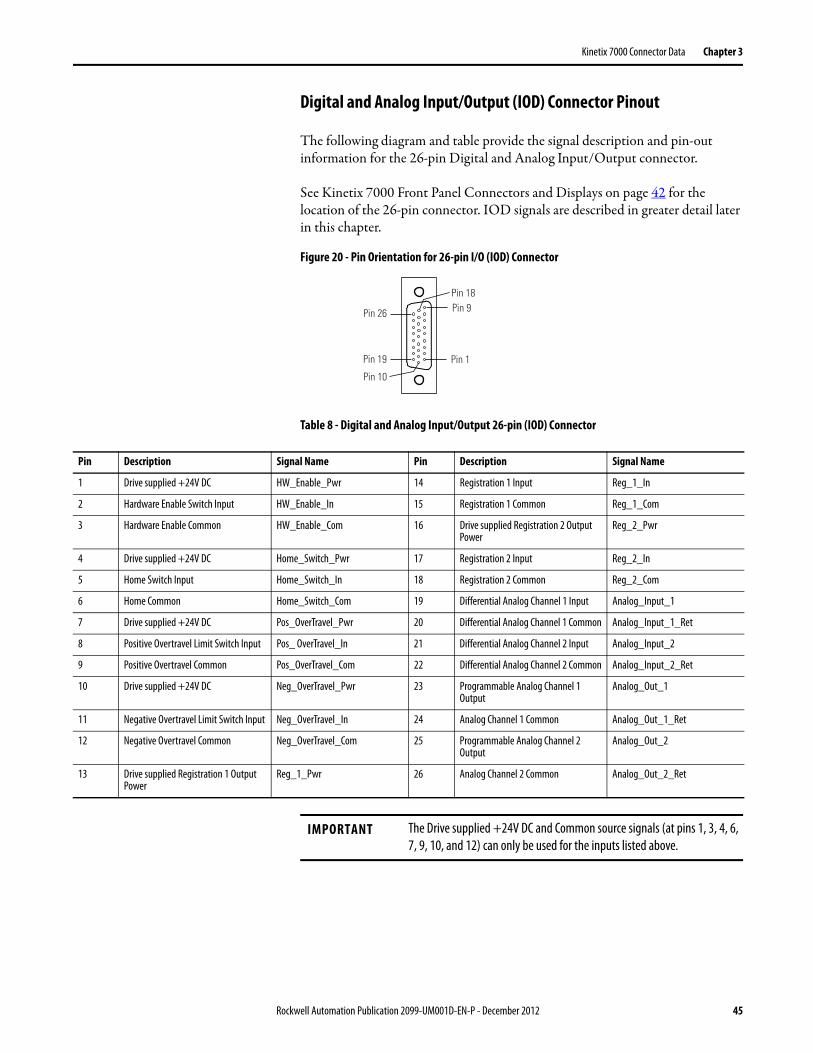
Digital and Analog Input/Output (IOD) Connector Pinout
The following diagram and table provide the signal description and pin-out information for the 26-pin Digital and Analog Input/Output connector.
See Kinetix 7000 Front Panel Connectors and Displays on page 42 for the location of the 26-pin connector. IOD signals are described in greater detail later in this chapter.
Figure 20 - Pin Orientation for 26-pin I/O (IOD) Connector
Table 8 - Digital and Analog Input/Output 26-pin (IOD) Connector
Pin 18
Pin 26
Pin 1
Pin 9
Pin 10
Pin 19
Pin Description Signal Name Pin Description Signal Name
1 Drive supplied +24V DC HW_Enable_Pwr 14 Registration 1 Input Reg_1_In
2 Hardware Enable Switch Input HW_Enable_In 15 Registration 1 Common Reg_1_Com
3 Hardware Enable Common HW_Enable_Com 16 Drive supplied Registration 2 Output Power
Reg_2_Pwr
4 Drive supplied +24V DC Home_Switch_Pwr 17 Registration 2 Input Reg_2_In
5 Home Switch Input Home_Switch_In 18 Registration 2 Common Reg_2_Com
6 Home Common Home_Switch_Com 19 Differential Analog Channel 1 Input Analog_Input_1
7 Drive supplied +24V DC Pos_OverTravel_Pwr 20 Differential Analog Channel 1 Common Analog_Input_1_Ret
8 Positive Overtravel Limit Switch Input Pos_ OverTravel_In 21 Differential Analog Channel 2 Input Analog_Input_2
9 Positive Overtravel Common Pos_OverTravel_Com 22 Differential Analog Channel 2 Common Analog_Input_2_Ret
10 Drive supplied +24V DC Neg_OverTravel_Pwr 23 Programmable Analog Channel 1 Output
Analog_Out_1
11 Negative Overtravel Limit Switch Input Neg_OverTravel_In 24 Analog Channel 1 Common Analog_Out_1_Ret
12 Negative Overtravel Common Neg_OverTravel_Com 25 Programmable Analog Channel 2 Output
Analog_Out_2
13 Drive supplied Registration 1 Output Power
Reg_1_Pwr 26 Analog Channel 2 Common Analog_Out_2_Ret
IMPORTANT The Drive supplied +24V DC and Common source signals (at pins 1, 3, 4, 6, 7, 9, 10, and 12) can only be used for the inputs listed above.
Rockwell Automation Publication 2099-UM001D-EN-P - December 2012 45

Chapter 3 Kinetix 7000 Connector Data
General Purpose I/O (GPIO) Terminal Block ConnectionsThe following diagram and table provide the orientation and signal description for the General Purpose Input/Output terminal block.
Figure 21 - Orientation for General Purpose I/O (GPIO) Terminal Block
Table 9 - General Purpose I/O (GPIO) Terminal Block
General Purpose Relay (GPR) Terminal Block ConnectionsThe following diagram and table provide the orientation and signal description for the General Purpose Relay terminal block.
Figure 22 - Orientation for General Purpose Relay (GPR) Terminal Block
Table 10 - General Purpose Relay (GPR) Terminal Block
Terminal Description Signal Name
1 Digital Output 1 Digital_Out_1
2 +24V DC for digital output 1 (customer-supplied) DO_24VDC_1
3 +24V DC for digital output 2 (customer-supplied) DO_24VDC_2
4 Digital Output 2 Digital_Out_2
5 Reserved N/C
6 Reserved N/C
7 Regenerative power supply OK (customer supplied) Regen_OK+
8 Common for Regenerative power supply OK Regen_OK-
Terminal Description Signal Name
1 24V DC customer-supplied power input for Relay 1 24VDC
2 Programmable N.O. Relay 1 output GPR1+
3 Programmable Relay 1 common GPR1-
4 24V DC customer-supplied power supply common COM
5 Programmable N.O. Relay 2 output GPR2+
6 Programmable Relay 2 common GPR2-
DO1
DO1_24
VDCDO2
DO2_24
VDCN/C N/C
REGEN
_OK+
REGEN
_OK-
GPIO
GPR2-COM
GPR2+GPR1-
GPR1+
24VDC
GPR
Note: The GPR terminal number orientation is rotated 180 degrees relative to the other I/O connectors.
46 Rockwell Automation Publication 2099-UM001D-EN-P - December 2012

Kinetix 7000 Connector Data Chapter 3
Motor Feedback (MF) Connector Pinouts
The following diagram and tables provide the orientation and signal description for the Motor Feedback (MF) connector for each applicable feedback device.
Figure 23 - Pin Orientation for 15-pin Motor Feedback (MF) Connector
Table 11 - Motor Feedback (MF) Connections for Stegmann Hiperface (SRS/SRM)
Table 12 - Motor Feedback (MF) Connections for TTL or Sine/Cosine with Index Pulse and Hall Commutation
Pin 11Pin 6
Pin 15
Pin 1
Pin 10Pin 5
Pin Description Signal Pin Description Signal
1 Sine differential input+ SIN+ 9 Reserved —
2 Sine differential input- SIN- 10 Hiperface data channel DATA-
3 Cosine differential input+ COS+ 11 Motor thermal switch (normally-closed) (1) TS
4 Cosine differential input- COS- 12 Reserved —
5 Hiperface data channel DATA+ 13 Reserved —
6 Common ECOM 14 Encoder power (+5V) EPWR_5V (2)
7 Encoder power (+9V) EPWR_9V (2) 15 Reserved —
8 Reserved —
(1) Not applicable unless the motor has integrated thermal protection.(2) Encoder power supply uses either 5V or 9V DC based on encoder/motor used.
Pin Description Signal Pin Description Signal
1 AM+ / Sine differential input+ AM+ / SIN+ 9 Reserved —
2 AM- / Sine differential input- AM- / SIN- 10 Index pulse- IM-
3 BM+ / Cosine differential input+ BM+ / COS+ 11 Motor thermal switch (normally-closed) (1) TS
4 BM- / Cosine differential input- BM- / COS- 12 Single-ended 5V hall effect commutation S1
5 Index pulse+ IM+ 13 Single-ended 5V hall effect commutation S2
6 Common ECOM 14 Encoder power (+5V) EPWR_5V (2)
7 Encoder power (+9V) EPWR_9V (2) 15 Reserved —
8 Single-ended 5V hall effect commutation S3
(1) Not applicable unless motor has integrated thermal protection.(2) Encoder power supply uses either 5V or 9V DC based on encoder/motor used.
Rockwell Automation Publication 2099-UM001D-EN-P - December 2012 47
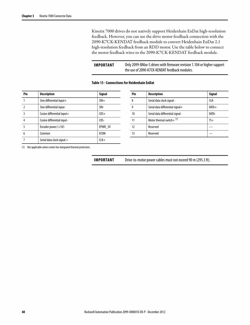
Chapter 3 Kinetix 7000 Connector Data
Kinetix 7000 drives do not natively support Heidenhain EnDat high-resolution feedback. However, you can use the drive motor feedback connection with the 2090-K7CK-KENDAT feedback module to convert Heidenhain EnDat 2.1 high-resolution feedback from an RDD motor. Use the table below to connect the motor feedback wires to the 2090-K7CK-KENDAT feedback module.
Table 13 - Connections for Heidenhain EnDat
IMPORTANT Only 2099-BMxx-S drives with firmware revision 1.104 or higher support the use of 2090-K7CK-KENDAT feedback modules.
Pin Description Signal Pin Description Signal
1 Sine differential input+ SIN+ 8 Serial data clock signal - CLK-
2 Sine differential input- SIN- 9 Serial data differential signal+ DATA+
3 Cosine differential input+ COS+ 10 Serial data differential signal - DATA-
4 Cosine differential input- COS- 11 Motor thermal switch+ (1) TS+
5 Encoder power (+5V) EPWR_5V 12 Reserved —
6 Common ECOM 13 Reserved —
7 Serial data clock signal + CLK+
(1) Not applicable unless motor has integrated thermal protection.
IMPORTANT Drive-to-motor power cables must not exceed 90 m (295.3 ft).
48 Rockwell Automation Publication 2099-UM001D-EN-P - December 2012
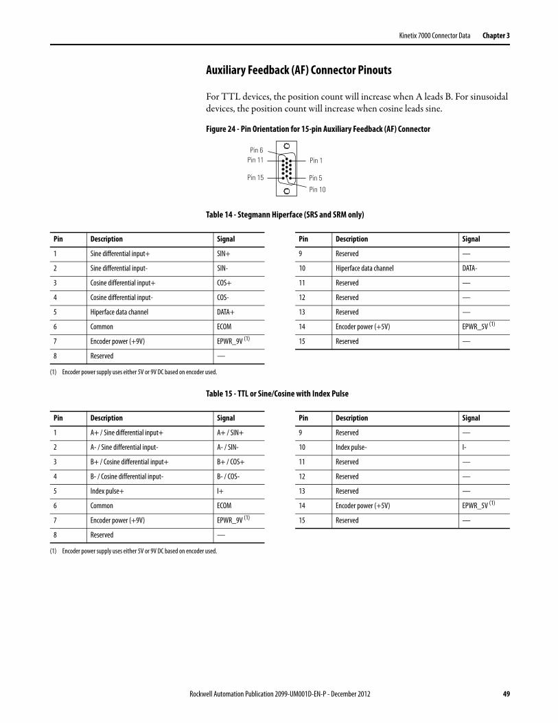
Kinetix 7000 Connector Data Chapter 3
Auxiliary Feedback (AF) Connector Pinouts
For TTL devices, the position count will increase when A leads B. For sinusoidal devices, the position count will increase when cosine leads sine.
Figure 24 - Pin Orientation for 15-pin Auxiliary Feedback (AF) Connector
Table 14 - Stegmann Hiperface (SRS and SRM only)
Table 15 - TTL or Sine/Cosine with Index Pulse
Pin 1Pin 11
Pin 10
Pin 5
Pin 6
Pin 15
Pin Description Signal Pin Description Signal
1 Sine differential input+ SIN+ 9 Reserved —
2 Sine differential input- SIN- 10 Hiperface data channel DATA-
3 Cosine differential input+ COS+ 11 Reserved —
4 Cosine differential input- COS- 12 Reserved —
5 Hiperface data channel DATA+ 13 Reserved —
6 Common ECOM 14 Encoder power (+5V) EPWR_5V (1)
7 Encoder power (+9V) EPWR_9V (1) 15 Reserved —
8 Reserved —
(1) Encoder power supply uses either 5V or 9V DC based on encoder used.
Pin Description Signal Pin Description Signal
1 A+ / Sine differential input+ A+ / SIN+ 9 Reserved —
2 A- / Sine differential input- A- / SIN- 10 Index pulse- I-
3 B+ / Cosine differential input+ B+ / COS+ 11 Reserved —
4 B- / Cosine differential input- B- / COS- 12 Reserved —
5 Index pulse+ I+ 13 Reserved —
6 Common ECOM 14 Encoder power (+5V) EPWR_5V (1)
7 Encoder power (+9V) EPWR_9V (1) 15 Reserved —
8 Reserved —
(1) Encoder power supply uses either 5V or 9V DC based on encoder used.
Rockwell Automation Publication 2099-UM001D-EN-P - December 2012 49

Chapter 3 Kinetix 7000 Connector Data
Safe-off (SO) Terminal Block Connections
Figure 25 - Safe-off (SO) Terminal Block
Table 16 - Safe-off (SO) Terminal Block
Terminal Description Signal Name
1 Normally-closed monitoring contact for safety relay 2 FDBK2+
2 Return for safety relay 2 FDBK2-
3 Normally-closed monitoring contact for safety relay 1 FDBK1+
4 Return for safety relay 1 FDBK1-
5 Coil of safety relay 2 ENABLE2+
6 Common for safety relays 1 and 2 ENABLE-
7 Coil of safety relay 1 ENABLE1+
8 24V DC, 500 mA max., power for Safe Off circuit SO_24VDC
9 Common for 24V power Safe off circuit SO_COM
IMPORTANT Terminals 8 and 9 (24V+ and Common) are only used by the motion-allowed jumper. When using the Safe-off feature, the 24V supply must come from an external source.
FDBK2+
FDBK2-
FDBK1+
FDBK1-
ENABLE
2+
ENABLE
-
ENABLE
1+
SO_24V
DC
SO_COM
SO
50 Rockwell Automation Publication 2099-UM001D-EN-P - December 2012
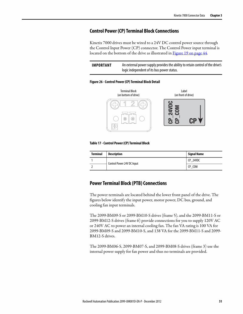
Kinetix 7000 Connector Data Chapter 3
Control Power (CP) Terminal Block Connections
Kinetix 7000 drives must be wired to a 24V DC control power source through the Control Input Power (CP) connector. The Control Power input terminal is located on the bottom of the drive as illustrated in Figure 19 on page 44.
Figure 26 - Control Power (CP) Terminal Block Detail
Table 17 - Control Power (CP) Terminal Block
Power Terminal Block (PTB) Connections
The power terminals are located behind the lower front panel of the drive. The figures below identify the input power, motor power, DC bus, ground, and cooling fan input terminals.
The 2099-BM09-S or 2099-BM10-S drives (frame 5), and the 2099-BM11-S or 2099-BM12-S drives (frame 6) provide connections for you to supply 120V AC or 240V AC to power an internal cooling fan. The fan VA rating is 100 VA for 2099-BM09-S and 2099-BM10-S, and 138 VA for the 2099-BM11-S and 2099-BM12-S drives.
The 2099-BM06-S, 2099-BM07-S, and 2099-BM08-S drives (frame 3) use the internal power supply for fan power and thus no terminals are provided.
IMPORTANT An external power supply provides the ability to retain control of the drive’s logic independent of its bus power status.
Terminal Description Signal Name
1Control Power 24V DC Input
CP_24VDC
2 CP_COM
CPCP_2
4VDC
CP_C
OM
Terminal Block(on bottom of drive)
Label(on front of drive)
Rockwell Automation Publication 2099-UM001D-EN-P - December 2012 51

Chapter 3 Kinetix 7000 Connector Data
Figure 27 - 2099-BM06-S, 2099-BM07-S, and 2099-BM08-S
Figure 28 - 2099-BM09-S
Figure 29 - 2099-BM10-S
DC+
DC-
U V W
R (L1
)
S (L2
)
T (L3
)
Cable clamps for Motor and AC inputs.
PS+
PS-
NC NC
DC+
DC
- U V W
PE
PE
R (L1
) S (
L2)
T (L3
)
PS+
PS-
Motor
FAN
AC Line
Fan Terminals Enlarged View
0 VAC
120 V
AC24
0 VAC
Fan Terminals Enlarged View
PS+
PS-
0 VAC
120 V
AC24
0 VAC
DC+
DC-
U V W
PE
PE
R (L1
)
S (L2
)
T (L3
)
FAN
Motor AC Line
52 Rockwell Automation Publication 2099-UM001D-EN-P - December 2012
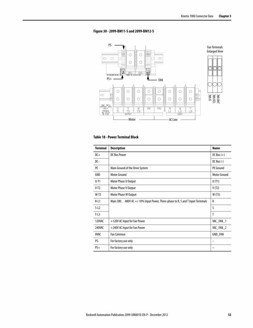
Kinetix 7000 Connector Data Chapter 3
Figure 30 - 2099-BM11-S and 2099-BM12-S
Table 18 - Power Terminal Block
Terminal Description Name
DC+ DC Bus Power DC Bus (+)
DC- DC Bus (-)
PE Main Ground of the Drive System PE Ground
GND Motor Ground Motor Ground
U-T1 Motor Phase U Output U (T1)
V-T2 Motor Phase V Output V (T2)
W-T3 Motor Phase W Output W (T3)
R-L1 Main 380…480V AC +/-10% Input Power, Three-phase to R, S and T Input Terminals R
S-L2 S
T-L3 T
120VAC +120V AC Input for Fan Power VAC_FAN_1
240VAC +240V AC Input for Fan Power VAC_FAN_2
0VAC Fan Common GND_FAN
PS- For factory use only –
PS+ For factory use only –
FAN PS+
PS-
Motor AC Line
Fan Terminals Enlarged View
0 VAC
120 V
AC24
0 VAC
Rockwell Automation Publication 2099-UM001D-EN-P - December 2012 53

Chapter 3 Kinetix 7000 Connector Data
Control Signal Specifications This section provides specifications for the Kinetix 7000 drive input/output (IOD), SERCOS, motor feedback (MF), auxiliary feedback (AF) and brake (BC) connectors.
Digital Inputs (IOD Connector)
Two fast registration inputs and four other inputs are available for the machine interface on the Kinetix 7000 drive. The drive supplies 24V DC @ 300 mA for the purpose of registration, home, enable, over-travel positive, and over-travel negative inputs. These are sinking inputs that require a sourcing device. A 24V DC power and common connection is provided for each input.
Table 19 - Digital Input Descriptions
Table 20 - Digital Input Specifications
24V I/O Power
The Kinetix 7000 drive provides 24V DC power @ 300 mA total for the HW_Enable_Pwr, Home_Switch_Pwr, Pos_OverTravel_Pwr, Neg_OverTravel_Pwr, Reg_1_Pwr, and Reg_2_Pwr inputs on the specific drive. The supply is protected with an automatically reset fuse. A temperature versus time curve automatically controls closing of the fuse.
A common mode choke filters the registration power connection. An additional common mode choke is provided for the remaining inputs.
IMPORTANT To improve registration input EMC performance, see the System Design for Control of Electrical Noise Reference Manual, publication GMC-RM001.
IOD Pin Signal Description Capture Time Edge/Level Sensitive
IOD-2 ENABLE Single optically isolated, single-ended active high signal. Current loading is nominally 10 mA. A 24V DC input is applied to this terminal to enable each axis.
20 ms Level
IOD-5 HOME Single optically isolated, single-ended active high signal. Current loading is nominally 10 mA. Home switch (normally-open contact) inputs for each axis require 24V DC (nominal).
20 ms Level
IOD-14IOD-17
REG1REG2
Fast registration inputs are required to inform the motor interface to capture the positional information with less than 3 μs uncertainty. Single optically isolated, single-ended active high signal. Current loading is nominally 10mA. A 24V DC input is applied to this terminal to enable each axis.
500 ns Edge
IOD-8IOD-11
OT+OT-
Overtravel detection is available as a dual-input, optically isolated, single-ended active high signal. Current loading is nominally 10 mA per input. The pos/neg limit switch (normally-closed contact) inputs for each axis require 24V DC (nominal).
20 ms Level
Parameter Description Min Max Leakage
ON-state voltage Voltage applied to the input, with respect to IOCOM, to guarantee an ON-state. 10.8V 26.4V —
ON-state current Current flow to guarantee an ON-state 3.0 mA 10.0 mA —
OFF-state voltage Voltage applied to the input, with respect to IOCOM, to guarantee an OFF-state. -1.0V 3.0V <1.5 mA
IMPORTANT Signals +24V_PWR and +24V_COM are a 24V DC source that can be used only for the inputs listed below.
54 Rockwell Automation Publication 2099-UM001D-EN-P - December 2012
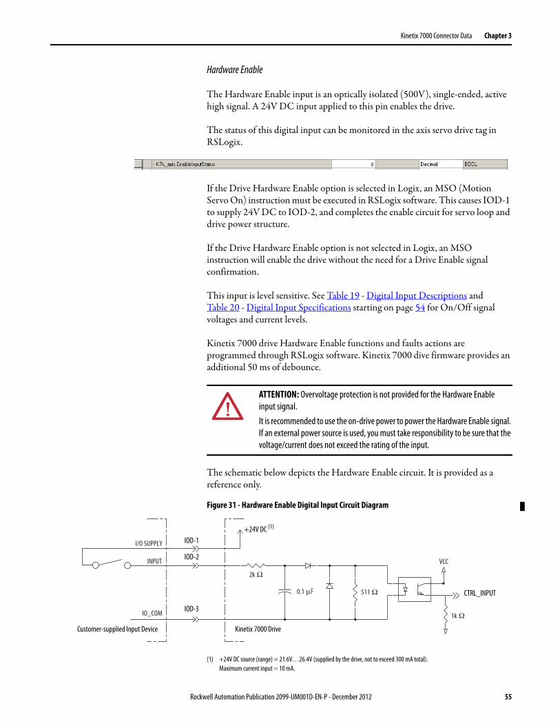
Kinetix 7000 Connector Data Chapter 3
Hardware Enable
The Hardware Enable input is an optically isolated (500V), single-ended, active high signal. A 24V DC input applied to this pin enables the drive.
The status of this digital input can be monitored in the axis servo drive tag in RSLogix.
If the Drive Hardware Enable option is selected in Logix, an MSO (Motion Servo On) instruction must be executed in RSLogix software. This causes IOD-1 to supply 24V DC to IOD-2, and completes the enable circuit for servo loop and drive power structure.
If the Drive Hardware Enable option is not selected in Logix, an MSO instruction will enable the drive without the need for a Drive Enable signal confirmation.
This input is level sensitive. See Table 19 - Digital Input Descriptions and Table 20 - Digital Input Specifications starting on page 54 for On/Off signal voltages and current levels.
Kinetix 7000 drive Hardware Enable functions and faults actions are programmed through RSLogix software. Kinetix 7000 dive firmware provides an additional 50 ms of debounce.
The schematic below depicts the Hardware Enable circuit. It is provided as a reference only.
Figure 31 - Hardware Enable Digital Input Circuit Diagram
(1) +24V DC source (range) = 21.6V…26.4V (supplied by the drive, not to exceed 300 mA total). Maximum current input = 10 mA.
ATTENTION: Overvoltage protection is not provided for the Hardware Enable input signal.It is recommended to use the on-drive power to power the Hardware Enable signal. If an external power source is used, you must take responsibility to be sure that the voltage/current does not exceed the rating of the input.
2k Ω
0.1 μF 511 Ω
VCCINPUT
IO_COM
I/O SUPPLY
1k Ω
Kinetix 7000 DriveCustomer-supplied Input Device
+24V DC (1)
CTRL_INPUT
IOD-1
IOD-3
IOD-2
Rockwell Automation Publication 2099-UM001D-EN-P - December 2012 55

Chapter 3 Kinetix 7000 Connector Data
Home
The Home input is an optically isolated (500V), single-ended, active high signal. A 24V DC input applied to this pin by a normally-open contact indicates this axis is in the home position. Firmware provides an additional 50 ms of debounce.
You can configure the required Home type in the axis servo drive properties in RSLogix. You can monitor the Home input “on/off ” status in the axis servo drive tag.
This input is level sensitive. See Table 19 - Digital Input Descriptions and Table 20 - Digital Input Specifications starting on page 54 for On/Off signal voltages and current levels.
The schematic below depicts the Home circuit. It is provided as a reference only.
Figure 32 - Home Digital Input Circuit Diagram
(1) +24V DC source (range) = 21.6…26.4V (supplied by the drive, not to exceed 300 mA total). Maximum current input = 10 mA.
ATTENTION: Overvoltage protection is not provided for the Home input signal.It is recommended to use the on-drive power to power the Home signal. If an external power source is used, you must take responsibility to be sure that the voltage/current does not exceed the rating of the input.
2k Ω
0.1 μF 511 Ω
VCCINPUT
IO_COM
I/O SUPPLY
1k Ω
Kinetix 7000 DriveCustomer-supplied Input Device
24V DC (1)
CTRL_INPUT
IOD-4
IOD-6
IOD-5
56 Rockwell Automation Publication 2099-UM001D-EN-P - December 2012

Kinetix 7000 Connector Data Chapter 3
Positive and Negative Overtravel
The Positive and Negative Overtravel detection is provided by two optically isolated (500V), single-ended, normally-closed, active high signals. Breaking the 24V DC input at either pin indicates an overtravel condition.
You can enable hard travel limits on the axis servo drive Limit tab in RSLogix. Hard travel limits require power to both the positive and negative overtravel inputs. You can monitor the positive and negative overtravel input status in the axis servo drive tag.
Notes:• A status of “1” indicates a normally closed input and a drive ready for
movement.• Hard overtravel limits can only be selected in a linear conversion selection.
This input is level sensitive. See Table 19 - Digital Input Descriptions and Table 20 - Digital Input Specifications starting on page 54 for On/Off signal voltages and current levels.
Kinetix 7000 drive Positive and Negative Overtravel functions and faults actions are programmed through RSLogix software. Kinetix 7000 drive firmware provides an additional 50ms of debounce.
The schematic below depicts the Positive and Negative Overtravel circuits. It is provided as a reference only.
Figure 33 - Positive and Negative Overtravel Input Diagram
(1) +24V DC source (range) = 21.6…26.4V (supplied by the drive, not to exceed 300 mA total). Maximum current input = 10 mA.
IMPORTANT Overtravel limit input devices must be normally-closed.
ATTENTION: Overvoltage protection is not provided for the Positive and Negative Overtravel input signal.It is recommended to use the on drive power to power the Positive and Negative Overtravel signals. If an external power source is used, you must take responsibility to be sure that the voltage/current does not exceed the rating of the input.
2k Ω
0.1 μF 511 Ω
VCCINPUT
IO_COM
I/O SUPPLY
1k Ω
Kinetix 7000 DriveCustomer-supplied Input Device
+24V DC (1)
Positive Overtravel or Negative Overtravel
IOD-7, 10
IOD-9, 12
IOD-8, 9
Rockwell Automation Publication 2099-UM001D-EN-P - December 2012 57
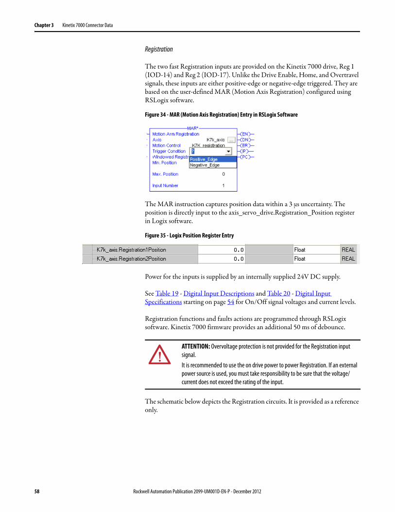
Chapter 3 Kinetix 7000 Connector Data
Registration
The two fast Registration inputs are provided on the Kinetix 7000 drive, Reg 1 (IOD-14) and Reg 2 (IOD-17). Unlike the Drive Enable, Home, and Overtravel signals, these inputs are either positive-edge or negative-edge triggered. They are based on the user-defined MAR (Motion Axis Registration) configured using RSLogix software.
Figure 34 - MAR (Motion Axis Registration) Entry in RSLogix Software
The MAR instruction captures position data within a 3 μs uncertainty. The position is directly input to the axis_servo_drive.Registration_Position register in Logix software.
Figure 35 - Logix Position Register Entry
Power for the inputs is supplied by an internally supplied 24V DC supply.
See Table 19 - Digital Input Descriptions and Table 20 - Digital Input Specifications starting on page 54 for On/Off signal voltages and current levels.
Registration functions and faults actions are programmed through RSLogix software. Kinetix 7000 firmware provides an additional 50 ms of debounce.
The schematic below depicts the Registration circuits. It is provided as a reference only.
ATTENTION: Overvoltage protection is not provided for the Registration input signal.It is recommended to use the on drive power to power Registration. If an external power source is used, you must take responsibility to be sure that the voltage/current does not exceed the rating of the input.
58 Rockwell Automation Publication 2099-UM001D-EN-P - December 2012
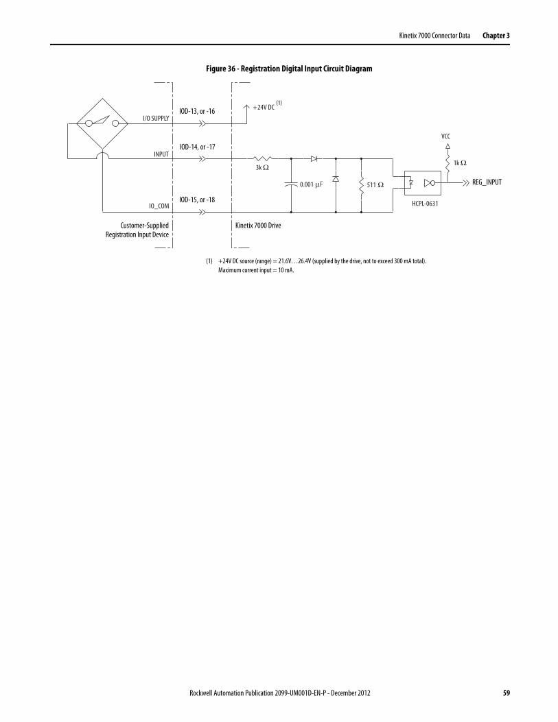
Kinetix 7000 Connector Data Chapter 3
Figure 36 - Registration Digital Input Circuit Diagram
(1) +24V DC source (range) = 21.6V…26.4V (supplied by the drive, not to exceed 300 mA total). Maximum current input = 10 mA.
3k Ω
0.001 μF 511 Ω
VCC
INPUT
IO_COM
I/O SUPPLY
1k Ω
+24V DC
HCPL-0631
Customer-SuppliedRegistration Input Device
Kinetix 7000 Drive
IOD-13, or -16
IOD-15, or -18
IOD-14, or -17
REG_INPUT
(1)
Rockwell Automation Publication 2099-UM001D-EN-P - December 2012 59
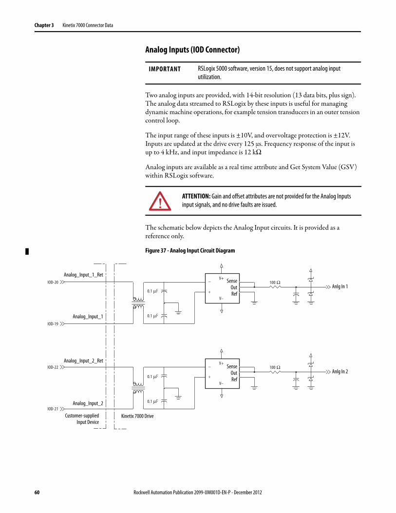
Chapter 3 Kinetix 7000 Connector Data
Analog Inputs (IOD Connector)
Two analog inputs are provided, with 14-bit resolution (13 data bits, plus sign). The analog data streamed to RSLogix by these inputs is useful for managing dynamic machine operations, for example tension transducers in an outer tension control loop.
The input range of these inputs is ±10V, and overvoltage protection is ±12V. Inputs are updated at the drive every 125 μs. Frequency response of the input is up to 4 kHz, and input impedance is 12 kΩ.
Analog inputs are available as a real time attribute and Get System Value (GSV) within RSLogix software.
The schematic below depicts the Analog Input circuits. It is provided as a reference only.
Figure 37 - Analog Input Circuit Diagram
IMPORTANT RSLogix 5000 software, version 15, does not support analog input utilization.
ATTENTION: Gain and offset attributes are not provided for the Analog Inputs input signals, and no drive faults are issued.
0.1 μF
0.1 μF
IOD-19
IOD-20 –
+
V+
V–
100 Ω
IOD-21
IOD-22 –
+
V+
V–
100 Ω
0.1 μF
0.1 μF
Analog_Input_1_Ret
Kinetix 7000 DriveCustomer-suppliedInput Device
Anlg In 1
Anlg In 2
SenseOutRef
Analog_Input_1
Analog_Input_2_Ret
Analog_Input_2
SenseOutRef
60 Rockwell Automation Publication 2099-UM001D-EN-P - December 2012
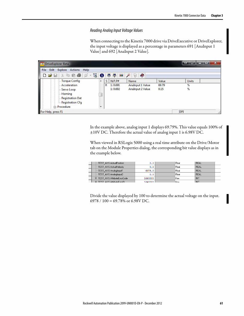
Kinetix 7000 Connector Data Chapter 3
Reading Analog Input Voltage Values
When connecting to the Kinetix 7000 drive via DriveExecutive or DriveExplorer, the input voltage is displayed as a percentage in parameters 691 [AnaInput 1 Value] and 692 [AnaInput 2 Value].
In the example above, analog input 1 displays 69.79%. This value equals 100% of ±10V DC. Therefore the actual value of analog input 1 is 6.98V DC.
When viewed in RSLogix 5000 using a real time attribute on the Drive/Motor tab on the Module Properties dialog, the corresponding bit value displays as in the example below.
Divide the value displayed by 100 to determine the actual voltage on the input. 6978 / 100 = 69.78% or 6.98V DC.
Rockwell Automation Publication 2099-UM001D-EN-P - December 2012 61

Chapter 3 Kinetix 7000 Connector Data
Analog Outputs (IOD Connector)
The two analog outputs (Analog_Out_1 and Analog_Out_2) are strictly for troubleshooting and cannot be used to drive other loads.
The analog outputs provide 12-bit resolution (11 data bits, plus sign) of the gain and filtering parameters within RSLogix software. In this way a data stream can be displayed by a meter or scale as velocity, torque, or following error information.
The ±10V outputs provide positive and negative direction range, with a null setting of 0V. For example, ±10V range, with 0V = 0. The drive update rate for these outputs is 125 μs, and is current limited to 25 mA.
Analog output functions are programmed in RSLogix software using a message instruction. The default pin assignments and the default gain values for the velocity, torque, and following error parameters are listed below.
A single pole low pass digital filter is provided for each analog output. The digital filter frequency range is 1…4 kHz.
The schematic depicts the Analog Output circuits. It is provided as a reference only.
Figure 38 - Analog Outputs Circuit Diagram
Signal Default Pin Parameter Gain Value Analog Output
Analog_Out_1 IOD-23 Velocity 0.0060 1V = 1000 rpm
Analog_Out_2 IOD-25 Torque 0.1 1V = 100% torque
IOD-26
IOD-25
–
+
V+
V–
–
+
V+
V–
3.9 μF
IOD-24
IOD-23
0.1 μF 0.1 μF
–
+
V+
V–
4.09 kΩ–
+
V+
V– 2.2 μF
3.9 μF
10 kΩ 10 kΩ
10 kΩ 10 kΩ
4.09 kΩ
100 kΩ
100 kΩ
10 kΩ
10 kΩ
10 kΩ
10 kΩ
2.2 μF
Analog_Out_1
Analog_Out_1_Ret
Analog_Out_2
Analog_Out_2_Ret
VDDSCLKSDINSYNCLDACSDOCLR
GND
RFSAIOUT1AIOUT2A
RFSBIOUT1BIOUT2BVRBFAVRBFB
62 Rockwell Automation Publication 2099-UM001D-EN-P - December 2012
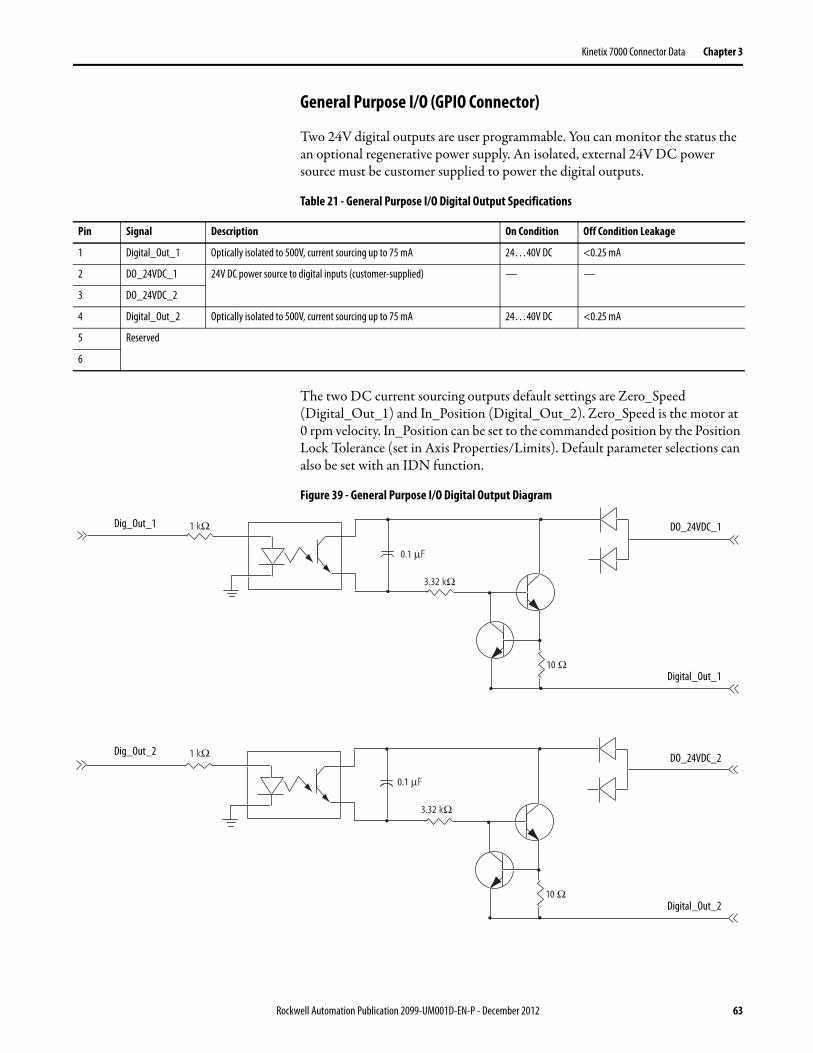
Kinetix 7000 Connector Data Chapter 3
General Purpose I/O (GPIO Connector)
Two 24V digital outputs are user programmable. You can monitor the status the an optional regenerative power supply. An isolated, external 24V DC power source must be customer supplied to power the digital outputs.
Table 21 - General Purpose I/O Digital Output Specifications
The two DC current sourcing outputs default settings are Zero_Speed (Digital_Out_1) and In_Position (Digital_Out_2). Zero_Speed is the motor at 0 rpm velocity. In_Position can be set to the commanded position by the Position Lock Tolerance (set in Axis Properties/Limits). Default parameter selections can also be set with an IDN function.
Figure 39 - General Purpose I/O Digital Output Diagram
Pin Signal Description On Condition Off Condition Leakage
1 Digital_Out_1 Optically isolated to 500V, current sourcing up to 75 mA 24…40V DC <0.25 mA
2 DO_24VDC_1 24V DC power source to digital inputs (customer-supplied) — —
3 DO_24VDC_2
4 Digital_Out_2 Optically isolated to 500V, current sourcing up to 75 mA 24…40V DC <0.25 mA
5 Reserved
6
1 kΩ
0.1 μF
3.32 kΩ
10 Ω
10 Ω
1 kΩ
0.1 μF
3.32 kΩ
DO_24VDC_1
Digital_Out_1
DO_24VDC_2
Digital_Out_2
Dig_Out_1
Dig_Out_2
Rockwell Automation Publication 2099-UM001D-EN-P - December 2012 63

Chapter 3 Kinetix 7000 Connector Data
The regenerative power supply OK provides status on the regenerative converter; in doing so, provides status to the Kinetix 7000 drive that there is DC bus power. Selecting the 8720MC-RPSxxx on the Power tab in the Kinetix 7000 drive I/O configuration in RSLogix requires the customer to provide a 24V DC power source to GPIO pins 7 and 8 as shown in Table 22 and in the interconnect diagrams in Appendix B. A failure to do so will cause a Regen_PS_OK (E111) fault, which indicates that he Regen_OK signal is missing at pins 7 and 8 of the GPIO connector. Kinetix 7000 drive firmware provides an additional 50 ms debounce.
Table 22 - General Purpose I/O Regenerative Power Supply OK Specifications
Figure 40 - General Purpose I/O Regenerative Power Supply OK Diagram
General Purpose Relay (GPR Connector)
Two general purpose relay connections are accessed through the GPR connector. GPR1+ is a normally-open, dry relay contact, supporting 2 A at 30V DC ±10% with suppression. This relay defaults to Motor Brake control, and specifically provides suppression. GPR2+ is a normally-open, dry relay contact, supporting 2 A at 250V AC or 2 A at 30V DC without suppression. This relay defaults to Drive OK. An external 24V DC power source must be supplied.
The following are default values for the general purpose relays.
Table 23 - General Purpose Relay Outputs Descriptions
Pin Signal Description On Condition Off Condition
7 Regen_OK+ Optically isolated (500V), single-ended active high signal 12…38V DC @ 3.3…12 mA
less than 6.6V DC, less than 1.5 mA
8 Regen_OK-
1 kΩ
511 Ω
2 kΩ
0.1 μF
VCC
Regen_OK+
Regen_OK- Regen_OK
Output: Default Relay Setting in RSLogix Software
Description
GPR1+ Motor Brake Turn-on and turn-off delays are specified by the Brake Engage Delay Time and Brake Release Delay Time in RSLogix software.
GPR2+ Drive OK (DROK)
64 Rockwell Automation Publication 2099-UM001D-EN-P - December 2012

Kinetix 7000 Connector Data Chapter 3
SERCOS Connections
Two fiber-optic connectors (transmit and receive) are provided on the Kinetix 7000 drive.
Table 24 - SERCOS Communications Specifications
Safe-off (SO Connector)
Kinetix 7000 drives provide safety functions and system integrity.
The Kinetix 7000 drive ships with a (9-pin) wiring-plug header having a motion-allowed jumper installed in the safe-off (SO) connector. With the motion-allowed jumper installed, the safe-off feature is disabled.
For safe-off wiring information, see the Kinetix Safe-off Feature Safety Reference Manual, publication GMC-RM002.
Figure 41 - Safe-Off, Motion-allowed Jumper
Control Power Specifications The following table provides specifications for the Control Power (CP) connector.
Specification Description
Data Rates 4 and 8 Mbps
Node Addresses 01…99 (1)
(1) Node addresses for additional axes on the same system are assigned by sequentially incrementing each additional axis. See Node Addressing Examples on page 108 for more information.
1
1 2 3 4 5 6 7 8 9
FDBK2+FDBK2-
FDBK1+FDBK1-
ENABLE2+
ENABLE-
ENABLE1+
SO_24VDC
SO_COM
SO
FDBK2+FDBK2-
FDBK1+FDBK1-
ENABLE2+
ENABLE-
ENABLE1+
SO_24VDC
SO_COM
SO
Motion-allowed Jumper
Wiring Plug Header
Safe-off(SO) Connector
Attribute Value
Auxiliary DC input voltage 24V DC, 3 A max, range 18…30 V DC
Rockwell Automation Publication 2099-UM001D-EN-P - December 2012 65

Chapter 3 Kinetix 7000 Connector Data
Motor (MF) and Auxiliary Feedback (AF) Connections
The motor interface and auxiliary feedback interfaces are consistent across the Kinetix product line. This section provides information on motor and auxiliary feedback connections.
The Kinetix 7000 motor (MF) and auxiliary (AF) feedback ports can accept the following encoder types:
• SRM/SRS Stegmann Hiperface encoders• 5V TTL differential line driver with index pulse and hall commutation• Sin/Cos differential input with index pulse and hall commutation
Motor feedback requires RSLogix 5000 motion.db file to properly commutate the motor. Motors available in RSLogix software include feedback types designated as S and M in Allen-Bradley catalog numbers. Following are further definitions of these feedback types.
• S type - single-turn 1024 cycles per rotation (interpolated to over 2 million counts in the drive) For example, the MPL-B980D-SJ72AA has this feedback type.
• M type - multi-turn 1024 cycles per rotation (interpolated to over 2 million counts in the drive). For example, the MPL-980D-MJ72AA has this feedback type. The “M” type allows for 4096 cycles absolute retention when the encoder is powered down.
RDD motor feedback from Heidenhain EnDat high-resolution encoders is also accepted, but only when using drive firmware revision 1.104 or higher and the 2090-K7CK-KENDAT low-profile feedback module.
Third-party motor requests must be pre-qualified and a custom motor file developed. Contact your local distributor or Rockwell Automation Sale Representative for more information.
Kinetix 7000 drives cannot drive open loop (no feedback) or other motor types not defined in the Kinetix motor database.
Motor and Auxiliary Feedback Specifications
AM, BM, and IM input encoder signals are filtered using analog and digital filtering. The inputs also include illegal state change detection. Figure 42 is a schematic of the AM, BM, and IM inputs.
66 Rockwell Automation Publication 2099-UM001D-EN-P - December 2012
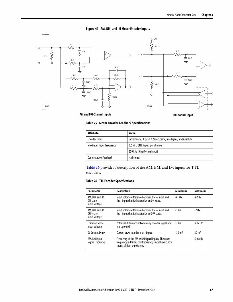
Kinetix 7000 Connector Data Chapter 3
Figure 42 - AM, BM, and IM Motor Encoder Inputs
Table 25 - Motor Encoder Feedback Specifications
Table 26 provides a description of the AM, BM, and IM inputs for TTL encoders.
Table 26 - TTL Encoder Specifications
+5 V
+
-
56 pF
56 pF
10k Ω
1k Ω
1k Ω
100 pF
+
-
100 pF
56 pF
56 pF
1k Ω
1k Ω 1k Ω
1k Ω1k Ω56 pF
56 pF
10k Ω
10k Ω
10k Ω
1k Ω
1k Ω
AM and BM Channel Inputs IM Channel Input
Drive Drive
Attribute Value
Encoder Types Incremental, A quad B, Sine/Cosine, Intelligent, and Absolute
Maximum Input Frequency 5.0 MHz (TTL input) per channel
250 kHz (Sine/Cosine input)
Commutation Feedback Hall sensor
Parameter Description Minimum Maximum
AM, BM, and IM ON-state Input Voltage
Input voltage difference between the + input and the - input that is detected as an ON-state.
+1.0V +7.0V
AM, BM, and IM OFF-state Input Voltage
Input voltage difference between the + input and the - input that is detected as an OFF-state.
-1.0V -7.0V
Common Mode Input Voltage
Potential difference between any encoder signal and logic ground.
-7.0V +12.0V
DC Current Draw Current draw into the + or - input. -30 mA 30 mA
AM, BM InputSignal Frequency
Frequency of the AM or BM signal inputs. The count frequency is 4 times this frequency, since the circuitry counts all four transitions.
— 5.0 MHz
Rockwell Automation Publication 2099-UM001D-EN-P - December 2012 67

Chapter 3 Kinetix 7000 Connector Data
The table provides a description of the AM and BM inputs for Sine/Cosine encoders.
Table 27 - AM, BM and IM Input Specifications for Sine/Cosine Encoders
Table 28 - Specifications for Heidenhain EnDat Encoders
Auxiliary Feedback (AF)
These requirements apply to the Auxiliary Feedback signals.• For TTL devices, the position count increases when A leads B.• For sinusoidal devices, the position count increases when cosine leads sine.• TTL devices must be 5V devices within the input voltage specification.• Use the Low Profile Connector Kit, catalog number 2090-K6CK-D15F to
access the Auxiliary Feedback signals. You must supply cabling that has shielding, and other EMI protection for motor feedback cables.
Feedback Power Supply
The power circuit board generates the +5V and +9V DC for the motor and auxiliary feedback power supplies. Short-circuit protection and separate common mode filtering for each channel is included.
• MPx-B, and HPK-B and -E motors all use 9V power sources from the MF connector.
• Compatible Auxiliary Feedback devices include Stegmann Hiperface, Sine/Cosine, and 5V TTL encoder types. Note: Heidenhain EnDat 2.1 encoders are only compatible when using the 2090-K7CK-KENDAT feedback module, however an interface module does not exist for the auxiliary encoder input.
IM Pulse Width Pulse width of the index input signal. Since the index is active for a percentage of a revolution, the speed will determine the pulse width.
125 nS —
AM, BM Phase Error2.5 MHz Line Frequency
Amount that the phase relationship between the AM and BM inputs can deviate from the nominal 90°.
-22.5° +22.5°
AM, BM Phase Error1 MHz Line Frequency
Amount that the phase relationship between the AM and BM inputs can deviate from the nominal 90°.
-45° +45°
Parameter Description Minimum Maximum
Sine/cosineInput Signal Frequency
Frequency of the Sine or Cosine signal inputs. — 250 kHz
Sine/cosine Input Voltage
Peak-to-peak input voltages of the Sine or Cosine inputs.
0.5V (p-p) 2.0V (p-p)
Command Set Order Designation
Description
EnDat 2.1 EnDat 01 1V (p-p) Sin/Cos, <2 MHz clock frequency
Parameter Description Minimum Maximum
68 Rockwell Automation Publication 2099-UM001D-EN-P - December 2012

Kinetix 7000 Connector Data Chapter 3
• See the Kinetix Motion Control Selection Guide, publication GMC-SG001, for cables compatible with the Kinetix 7000 drive and motor.
• Low profile connector let you develop a custom cable for the Motor Feedback (MF) or Auxiliary Feedback (AF) connectors.
The following table details power supply specifications for the motor and auxiliary feedback connectors.
Table 29 - Motor and Auxiliary Feedback Power Supply Specifications
Power Supply
Signal Name Voltage (V DC) Current (mA)
Min Nom Max Min Max
+5V EPWR_5V 5.13 5.4 5.67 10 400 (1) (3)
(1) 400 mA on the 5V supply split in any manner between the channels with no load on the 5V supply.
+9V EPWR_9V 8.3 9.1 9.9 10 275 (2) (3)
(2) 275 mA on the 9V supply split in any manner between the channels with no load on the 9V supply.(3) 300 mA on the 5V supply on one channel with 150 mA on the 9V supply on the second channel.
Rockwell Automation Publication 2099-UM001D-EN-P - December 2012 69

Chapter 3 Kinetix 7000 Connector Data
Notes:
70 Rockwell Automation Publication 2099-UM001D-EN-P - December 2012

Chapter 4
Connect the Kinetix 7000 Drive System
This chapter provides procedures for wiring your Kinetix 7000 drive system components and making cable connections.
Basic Wiring Requirements This section contains basic wiring information for the Kinetix 7000 drive.
Topic Page
Basic Wiring Requirements 71
Determine the Input Power Configuration 75
Setting the Ground Jumper in Ungrounded Power Configurations 78
Grounding the Kinetix 7000 Drive System 81
Input Power Wiring Requirements 85
Power Wiring Guidelines 88
Wire the Kinetix 7000 Drive Connectors 88
Feedback and I/O Cable Connections 93
Wire Feedback and I/O Connectors 95
External Shunt Module Connections 101
SERCOS Fiber-optic Cable Connections 101
ATTENTION: Plan the installation of your system so that you can perform all cutting, drilling, tapping, and welding with the system removed from the enclosure. Because the system is of the open type construction, be careful to keep any metal debris from falling into it. Metal debris or other foreign matter can become lodged in the circuitry, that can result in damage to components.
SHOCK HAZARD: To avoid hazard of electrical shock, perform all mounting and wiring prior to applying power. Once power is applied, connector terminals may have voltage present even when not in use.
IMPORTANT This section contains common PWM servo system wiring configurations, size, and practices that can be used in a majority of applications. National Electrical Code, local electrical codes, special operating temperatures, duty cycles, or system configurations take precedence over the values and methods provided.
Rockwell Automation Publication 2099-UM001D-EN-P - December 2012 71
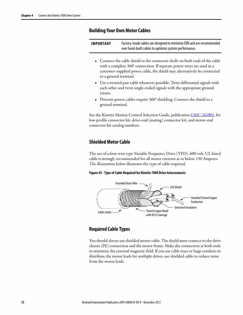
Chapter 4 Connect the Kinetix 7000 Drive System
Building Your Own Motor Cables
• Connect the cable shield to the connector shells on both ends of the cable with a complete 360° connection. If separate power wires are used in a customer-supplied power cable, the shield may alternatively be connected to a ground terminal.
• Use a twisted pair cable whenever possible. Twist differential signals with each other and twist single-ended signals with the appropriate ground return.
• Discrete power cables require 360° shielding. Connect the shield to a ground terminal.
See the Kinetix Motion Control Selection Guide, publication GMC-SG001, for low-profile connector kit, drive-end (mating) connector kit, and motor-end connector kit catalog numbers.
Shielded Motor Cable
The use of a four-wire type Variable Frequency Drive (VFD), 600 volt, UL listed cable is strongly recommended for all motor currents at or below 130 Amperes. The illustration below illustrates the type of cable required.
Figure 43 - Type of Cable Required for Kinetix 7000 Drive Interconnects
Required Cable Types
You should always use shielded motor cable. The shield must connect to the drive chassis (PE) connection and the motor frame. Make the connection at both ends to minimize the external magnetic field. If you use cable trays or large conduits to distribute the motor leads for multiple drives, use shielded cable to reduce noise from the motor leads.
IMPORTANT Factory-made cables are designed to minimize EMI and are recommended over hand-built cables to optimize system performance.
Stranded Drain WireFoil Shield
Oversized Insulation Cable Jacket
Stranded Tinned Copper Conductors
Tinned Copper Braid with 85% Coverage
72 Rockwell Automation Publication 2099-UM001D-EN-P - December 2012

Connect the Kinetix 7000 Drive System Chapter 4
Cable Sizes
In the table below the appropriate VFD shielded cable to use based on 150% overload capability and 25 °C (77 °F) operating temperature is shown.
For applications above 130 Amps, use thick insulation lead wire, such as RHW-2 or equal. Make sure you thread the four wires (U, V, W, and ground) through a single, grounded, metal conduit.
Table 30 - 1.5x Rated Continuous Motor Current Cable Size
Conduit
For applications above 130 Amperes, metal conduit is required for cable distribution. Follow these guidelines:
• Drives are normally mounted in cabinets, and ground connections are made at a common ground point in the cabinet. If the conduit is connected to the motor junction box and the drive end is connected to the ground panel in the cabinet, you do not need any additional conduit connections.
• Route no more than three sets of motor leads and a ground wire through a single conduit. This minimizes cross talk that also reduces the effectiveness of the noise reduction methods described. If more than three drive/motor connections per conduit are required, use shielded cable. If practical, each conduit should contain only one set of motor leads.
• You should use a thick insulation lead wire, such as type RHW-2 or equal.
Motor Current Cable Size
mm2 AWG
12 A 1.5 16
17 A 2.5 14
21 A 4 12
30 A 6 10
55 A 10 8
65 A 16 6
95 A 25 4
130 A 35 2
Rockwell Automation Publication 2099-UM001D-EN-P - December 2012 73
Chapter 4 Connect the Kinetix 7000 Drive System
General Wire Guidelines
Observe all applicable safety and national and local regulations when selecting the appropriate wire size for your system. Due to the drive overload capacity of 150% of the continuous current rating, the conductors for the transformer primary and secondary must be sized (at a minimum) for 125…160% of the maximum continuous input current for the motor selected. The motor conductors must also be rated for a minimum of 125…160% of the full load motor continuous current. If less than 150% overload is required the torque limit parameters must be set in the drive accordingly. The distance between the drive and motor may affect the size of the conductors used. To protect against interference, use shielded wire in motor and control circuits. A shielded cable is required for all feedback signal wires.
Routing the Power and Signal Cables
Be aware that when you route power and signal wiring on a machine or system, radiated noise from nearby relays, transformers, and other electronic drives can be induced into motor or encoder feedback signals, input/output communications, or other sensitive low voltage signals. This can cause system faults and communication problems.
See Minimizing Electrical Noise on page 28 for examples of routing high and low voltage cables in wireways, and to the System Design for Control of Electrical Noise Reference Manual, publication GMC-RM001, for more information.
ATTENTION: To avoid a possible shock hazard caused by induced voltages, ground unused wires in the conduit at both ends.For the same reason, if a drive sharing a conduit is being serviced or installed, disable all drives using this conduit. This removes the possible shock hazard from cross-coupled drive motor leads.
74 Rockwell Automation Publication 2099-UM001D-EN-P - December 2012

Connect the Kinetix 7000 Drive System Chapter 4
Determine the Input Power Configuration
Before wiring input power to your Kinetix 7000 drive system you must determine the type of input power to which you are connecting. The Kinetix 7000 drive is configured at the factory to operate in a grounded power environment.
Grounded Power Configurations
Grounded (WYE) power wiring lets you ground your three-phase power at a neutral point.
Figure 44 - Grounded Three-phase Power Wiring - WYE Secondary (Recommended)
ATTENTION: When using a LIM with your Kinetix 7000 drive, the AC line input power must come from a grounded configuration.When not using a LIM with your Kinetix 7000 drive, ungrounded configurations are acceptable, but you must set the jumper to prevent high electrostatic build-up.See Setting the Ground Jumper in Ungrounded Power Configurations on page 78 for additional information.
L1
L2
L3
2099-BM08-S shown withLower Front Panel Removed
Transformer (WYE) Secondary
Three-phaseInput VAC
Phase Ground
Transformer
Bonded CabinetGround
Ground Grid orPower Distribution Ground
To Ground Stud
Line Filter
Rockwell Automation Publication 2099-UM001D-EN-P - December 2012 75
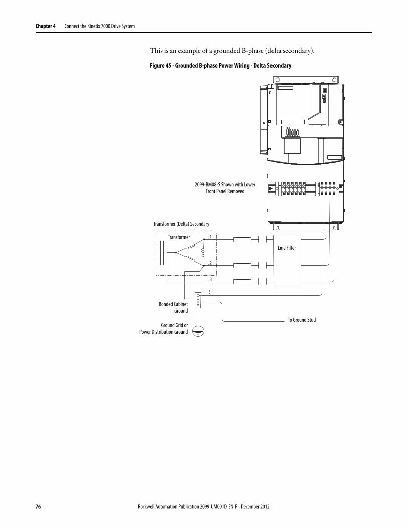
Chapter 4 Connect the Kinetix 7000 Drive System
This is an example of a grounded B-phase (delta secondary).
Figure 45 - Grounded B-phase Power Wiring - Delta Secondary
L1
L3
L2
2099-BM08-S Shown with Lower Front Panel Removed
Transformer (Delta) Secondary
Transformer
Bonded CabinetGround
Ground Grid orPower Distribution Ground
To Ground Stud
Line Filter
76 Rockwell Automation Publication 2099-UM001D-EN-P - December 2012
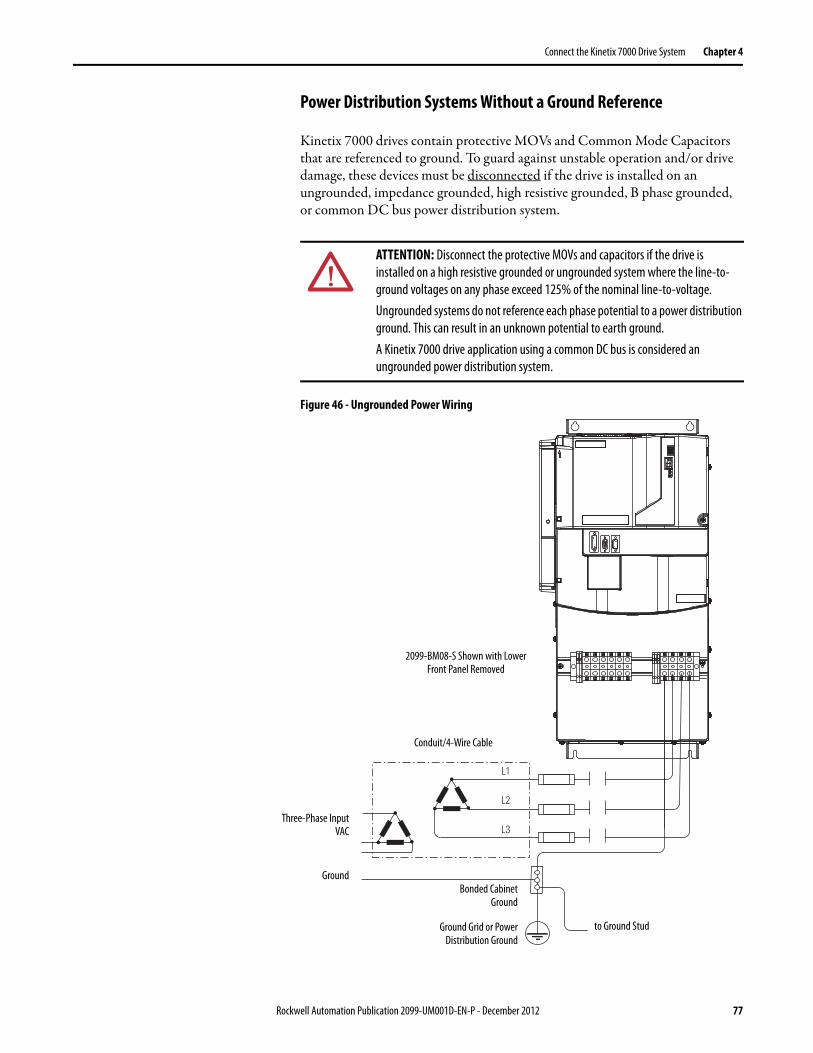
Connect the Kinetix 7000 Drive System Chapter 4
Power Distribution Systems Without a Ground Reference
Kinetix 7000 drives contain protective MOVs and Common Mode Capacitors that are referenced to ground. To guard against unstable operation and/or drive damage, these devices must be disconnected if the drive is installed on an ungrounded, impedance grounded, high resistive grounded, B phase grounded, or common DC bus power distribution system.
Figure 46 - Ungrounded Power Wiring
ATTENTION: Disconnect the protective MOVs and capacitors if the drive is installed on a high resistive grounded or ungrounded system where the line-to-ground voltages on any phase exceed 125% of the nominal line-to-voltage.Ungrounded systems do not reference each phase potential to a power distribution ground. This can result in an unknown potential to earth ground.A Kinetix 7000 drive application using a common DC bus is considered an ungrounded power distribution system.
L1
L2
L3
2099-BM08-S Shown with Lower Front Panel Removed
Conduit/4-Wire Cable
Three-Phase InputVAC
GroundBonded Cabinet
Ground
Ground Grid or PowerDistribution Ground
to Ground Stud
Rockwell Automation Publication 2099-UM001D-EN-P - December 2012 77
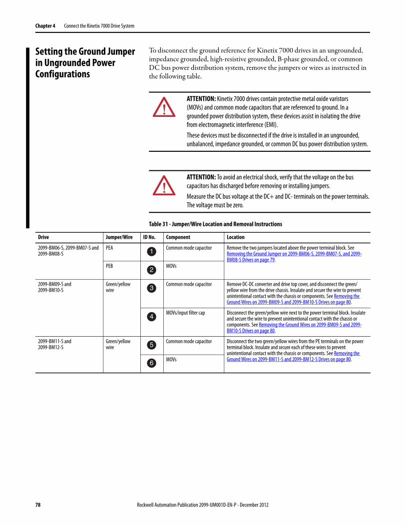
Chapter 4 Connect the Kinetix 7000 Drive System
Setting the Ground Jumper in Ungrounded Power Configurations
To disconnect the ground reference for Kinetix 7000 drives in an ungrounded, impedance grounded, high-resistive grounded, B-phase grounded, or common DC bus power distribution system, remove the jumpers or wires as instructed in the following table.
Table 31 - Jumper/Wire Location and Removal Instructions
ATTENTION: Kinetix 7000 drives contain protective metal oxide varistors (MOVs) and common mode capacitors that are referenced to ground. In a grounded power distribution system, these devices assist in isolating the drive from electromagnetic interference (EMI).These devices must be disconnected if the drive is installed in an ungrounded, unbalanced, impedance grounded, or common DC bus power distribution system.
ATTENTION: To avoid an electrical shock, verify that the voltage on the bus capacitors has discharged before removing or installing jumpers.Measure the DC bus voltage at the DC+ and DC- terminals on the power terminals. The voltage must be zero.
Drive Jumper/Wire ID No. Component Location
2099-BM06-S, 2099-BM07-S and 2099-BM08-S
PEA Common mode capacitor Remove the two jumpers located above the power terminal block. See Removing the Ground Jumper on 2099-BM06-S, 2099-BM07-S, and 2099-BM08-S Drives on page 79.
PEB MOVs
2099-BM09-S and 2099-BM10-S
Green/yellow wire
Common mode capacitor Remove DC-DC converter and drive top cover, and disconnect the green/yellow wire from the drive chassis. Insulate and secure the wire to prevent unintentional contact with the chassis or components. See Removing the Ground Wires on 2099-BM09-S and 2099-BM10-S Drives on page 80.
MOVs/input filter cap Disconnect the green/yellow wire next to the power terminal block. Insulate and secure the wire to prevent unintentional contact with the chassis or components. See Removing the Ground Wires on 2099-BM09-S and 2099-BM10-S Drives on page 80.
2099-BM11-S and 2099-BM12-S
Green/yellow wire
Common mode capacitor Disconnect the two green/yellow wires from the PE terminals on the power terminal block. Insulate and secure each of these wires to prevent unintentional contact with the chassis or components. See Removing the Ground Wires on 2099-BM11-S and 2099-BM12-S Drives on page 80.MOVs
1
2
3
4
5
6
78 Rockwell Automation Publication 2099-UM001D-EN-P - December 2012
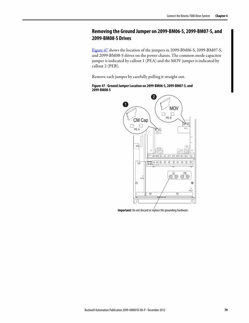
Connect the Kinetix 7000 Drive System Chapter 4
Removing the Ground Jumper on 2099-BM06-S, 2099-BM07-S, and 2099-BM08-S Drives
Figure 47 shows the location of the jumpers in 2099-BM06-S, 2099-BM07-S, and 2099-BM08-S drives on the power chassis. The common mode capacitor jumper is indicated by callout 1 (PEA) and the MOV jumper is indicated by callout 2 (PEB).
Remove each jumper by carefully pulling it straight out.
Figure 47 - Ground Jumper Location on 2099-BM06-S, 2099-BM07-S, and2099-BM08-S
BR1 BR2 DC+ DC- U/T1 V/T2 W/T3 R/L1 S/L2 T/L3
PE B
PE A
75C Cu Wire3 AWG [25MM2] Max.
16 IN. LBS.1.8 N-M } TORQUE
WIRESTRIP
CO
NTR
OL
POW
ER
AUX IN+ –
SHLD
SHLD
PE
75C Cu Wire6 AWG [10MM2] Max.
BR1 BR2
12 IN. LBS.1.4 N-M } TORQUE
PE A
PE BCM Cap
MOV1
2
Important: Do not discard or replace the grounding hardware.
Rockwell Automation Publication 2099-UM001D-EN-P - December 2012 79

Chapter 4 Connect the Kinetix 7000 Drive System
Removing the Ground Wires on 2099-BM09-S and 2099-BM10-S DrivesFigure 48 shows the locations of the common mode capacitor and MOV/input filter capacitor ground wires in 2099-BM09-S and 2099-BM10-S drives. The common mode capacitor ground wire is indicated by callout 3 and the MOV/input filter cap ground wire is indicated by callout 4.
Figure 48 - Ground Wire Locations on Terminal Block of 2099-BM09-S and 2099-BM10-S
Removing the Ground Wires on 2099-BM11-S and 2099-BM12-S DrivesFigure 49 shows the locations of the common mode capacitor and MOV ground wires in 2099-BM11-S and 2099-BM12-S drives. The common mode capacitor ground wire is indicated by callout 5 and the MOV ground wire is indicated by callout 6.
Figure 49 - Ground Wire Location on Power Terminal Block of 2099-BM11-S and 2099-BM12-S
WIRE RANGE: 14-1/0 AWG (2.5-35 MM2)TORQUE: 32 IN-LB (3.6 N-M)STRIP LENGTH: 0.67 IN (17 MM)USE 75 C CU WIRE ONLY
POWER TERMINAL RATINGS
WIRE RANGE: 6-1/0 AWG (16-35 MM2)TORQUE: 44 IN-LB (5 N-M)STRIP LENGTH: 0.83 IN (21 MM)
GROUND TERMINAL RATINGS (PE)
300 VDC EXT PWR SPLY TERM (PS+, PS-)
WIRE RANGE: 22-10 AWG (0.5-4 MM2)TORQUE: 5.3 IN-LB (0.6 N-M)STRIP LENGTH: 0.35 IN (9 MM)
17
21
INPUT ACOUTPUT
OptionalCommunications
Module
9
Note: You must remove the DC-DC converter and drive top cover to access and remove the common mode capacitor ground wire. See the Kinetix 7000 DC-DC Converter and Control Board Kits Installation instructions, publication 2099-IN002, for instructions.
3 CM Cap - Older Drives
3 CM Cap - Newer Drives
4 MOV
4
MOV/Input Filter Cap
UT1
VT2
WT3
RL1
SL2
INPUTOUTPUT
TL3
PE PE
PE PE
MOVCM Cap5
6
DO NOT REMOVE
80 Rockwell Automation Publication 2099-UM001D-EN-P - December 2012

Connect the Kinetix 7000 Drive System Chapter 4
Grounding the Kinetix 7000 Drive System
All equipment and components of a machine or process system must have a common earth ground point connected to their chassis.
A grounded system provides a ground path for short-circuit protection. Grounding your modules and panels minimize shock hazard to personnel and damage to equipment caused by short-circuits, transient overvoltages, and accidental connection of energized conductors to the equipment chassis.
See Agency Compliance on page 18 for CE grounding requirements.
Grounding Your System to the Subpanel
In Figure 50, the drive is shown properly grounded to the bonded cabinet ground on the subpanel.
Figure 50 - Drive Chassis Ground Connection
IMPORTANT To improve the bond between the drive and subpanel, construct your subpanel out of zinc-plated (paint-free) steel.
ATTENTION: The National Electrical Code contains grounding requirements, conventions, and definitions. Follow all applicable local codes and regulations to safely ground your system.See the Interconnect Diagram Notes diagrams beginning on page 162.
Ground grid or powerdistribution ground *
Bonded Cabinet Ground *
Braided Ground Strap *
* Indicates customer-supplied item.
Kinetix 7000 Drive
Rockwell Automation Publication 2099-UM001D-EN-P - December 2012 81
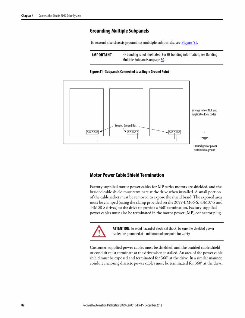
Chapter 4 Connect the Kinetix 7000 Drive System
Grounding Multiple Subpanels
To extend the chassis ground to multiple subpanels, see Figure 51.
Figure 51 - Subpanels Connected to a Single Ground Point
Motor Power Cable Shield Termination
Factory-supplied motor power cables for MP-series motors are shielded, and the braided cable shield must terminate at the drive when installed. A small portion of the cable jacket must be removed to expose the shield braid. The exposed area must be clamped (using the clamp provided on the 2099-BM06-S, -BM07-S and -BM08-S drives) to the drive to provide a 360° termination. Factory-supplied power cables must also be terminated in the motor power (MP) connector plug.
Customer-supplied power cables must be shielded, and the braided cable shield or conduit must terminate at the drive when installed. An area of the power cable shield must be exposed and terminated for 360° at the drive. In a similar manner, conduit enclosing discrete power cables must be terminated for 360° at the drive.
IMPORTANT HF bonding is not illustrated. For HF bonding information, see Bonding Multiple Subpanels on page 30.
Always follow NEC and applicable local codes
Ground grid or power distribution ground
Bonded Ground Bus
ATTENTION: To avoid hazard of electrical shock, be sure the shielded power cables are grounded at a minimum of one point for safety.
82 Rockwell Automation Publication 2099-UM001D-EN-P - December 2012
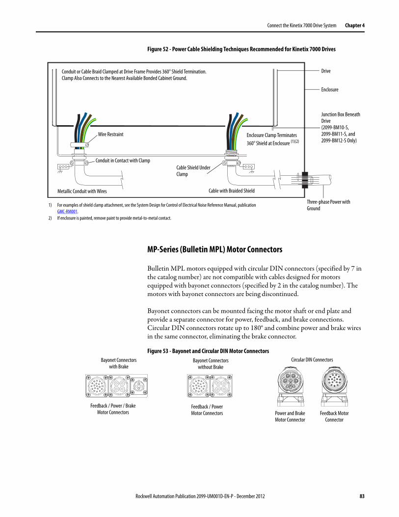
Connect the Kinetix 7000 Drive System Chapter 4
Figure 52 - Power Cable Shielding Techniques Recommended for Kinetix 7000 Drives
MP-Series (Bulletin MPL) Motor Connectors
Bulletin MPL motors equipped with circular DIN connectors (specified by 7 in the catalog number) are not compatible with cables designed for motors equipped with bayonet connectors (specified by 2 in the catalog number). The motors with bayonet connectors are being discontinued.
Bayonet connectors can be mounted facing the motor shaft or end plate and provide a separate connector for power, feedback, and brake connections. Circular DIN connectors rotate up to 180° and combine power and brake wires in the same connector, eliminating the brake connector.
Figure 53 - Bayonet and Circular DIN Motor Connectors
DriveConduit or Cable Braid Clamped at Drive Frame Provides 360° Shield Termination. Clamp Also Connects to the Nearest Available Bonded Cabinet Ground.
Enclosure
Wire Restraint
Cable Shield Under Clamp
Cable with Braided ShieldMetallic Conduit with Wires
Conduit in Contact with Clamp
1) For examples of shield clamp attachment, see the System Design for Control of Electrical Noise Reference Manual, publication GMC-RM001.
2) If enclosure is painted, remove paint to provide metal-to-metal contact.
Junction Box Beneath Drive(2099-BM10-S,2099-BM11-S, and 2099-BM12-S Only)
Three-phase Power with Ground
Enclosure Clamp Terminates 360° Shield at Enclosure (1)(2)
Bayonet Connectorswith Brake
Bayonet Connectorswithout Brake
Feedback / Power Motor Connectors
Feedback / Power / BrakeMotor Connectors
Circular DIN Connectors
Power and Brake Motor Connector
Feedback Motor Connector
Rockwell Automation Publication 2099-UM001D-EN-P - December 2012 83

Chapter 4 Connect the Kinetix 7000 Drive System
Table 32 - Motor Power Cable Compatibility
Motors may have a separate brake connector or need routing of thermal switch wires. These are often separately shielded and routed in an existing cable.
See Wiring Examples beginning on page 162 for interconnect diagrams, and the Power Terminal Block (PTB) Connections diagram on page 51 for the location of the U, V, W, and ground (PE) motor power terminals.
Motor/Actuator Connector Motor/Actuator Cat. No. Motor Power Cables(with brake wires)
Motor Power Cables(without brake wires)
MP-Series (Bulletin MPL) Circular DIN MPL-B5xxx, MPL-B6xxx, MPL-B8xxx, and MPL-B9xxx
2090-CPBM7DF-xxAAxx or 2090-XXNPMF-xxSxx(standard, non-flex)2090-CPBM7DF-xxAFxx (1)
(continuous-flex)
2090-CPWM7DF-xxAAxx (standard, non-flex)2090-CPWM7DF-xxAFxx (1)
(continuous-flex)
Bayonet MPL-A/B5xxx, MPL-B6xxx, and MPL-B8xxxMPL-B960B, MPL-B960C, MPL-B980B, and MPL-B980C
N/A 2090-XXxPMP-xxSxx (2)
MPL-B960D and MPL-B980D 2090-MCNPMP-6Sxx
MP-Series (Bulletin MPM) Circular DIN MPM-B165 and MPM-B215 2090-CPBM7DF-xxAAxx or 2090-XXNPMF-xxSxx(standard, non-flex)2090-CPBM7DF-xxAFxx (1)
(continuous-flex)
2090-CPWM7DF-xxAAxx (standard, non-flex)2090-CPWM7DF-xxAFxx (1)
(continuous-flex)
RDD-Series Circular DIN RDB-Bxxxx N/A 2090-CPWM7DF-xxAAxx (standard, non-flex)2090-CPWM7DF-xxAFxx (1)
(continuous-flex)
HPK-Series N/A HPK-Bxxxxx, HPK-Exxxxx Customer-supplied
(1) You must remove the motor-side o-ring when using 2090-CPxM7DF-xxAxxx cables.(2) For Bulletin MPL motors equipped with bayonet connectors. These cables are available as standard, non-flex (catalog number 2090-XXNPMP-xxSxx) and continuous-flex (catalog number 2090-XXTPMP-
xxSxx).
IMPORTANT Securing the cable shield in the clamp with a tie wrap is recommended to improve stress relief.
84 Rockwell Automation Publication 2099-UM001D-EN-P - December 2012

Connect the Kinetix 7000 Drive System Chapter 4
Input Power Wiring Requirements
National codes and standards (NEC, VDE, BSI etc.) and local codes outline provisions for safely installing electrical equipment. Installation must comply with specifications regarding wire types, conductor sizes, branch circuit protection and disconnect devices.
Acceptable Cable Types
Do not use cable with an insulation thickness less than or equal to 15 mils (0.4 mm/0.015 in.). Use copper wire only. Wire gauge requirements and recommendations are based on 75 ° C. Do not reduce wire gauge when using higher temperature wire.
As an approximate guide, provide spacing of 0.3 meters (1 foot) for every 10 meters (32.8 feet) of length. In all cases, long parallel runs must be avoided.
Shielded/Armored Cable
Shielded cable contains all of the general benefits of multi-conductor cable with the added benefit of a copper braided shield that can contain much of the noise generated by a typical AC drive. Strong consideration for shielded cable should be given in installations with sensitive equipment such as weigh scales, capacitive proximity switches and other devices that may be affected by electrical noise in the distribution system. Applications with large numbers of drives in a similar location, imposed EMC regulations, or a high degree of communications and networking are also good candidates for shielded cable.
Shielded cable may also help reduce shaft voltage and induced bearing currents for some applications. In addition, the increased impedance of shielded cable may help extend the distance that the motor can be located from the drive without the addition of motor protective devices such as terminator networks.
Consideration should be given to the general specifications dictated by the environment of the installation, including temperature, flexibility, moisture characteristics and chemical resistance. In addition, a braided shield should be included and be specified by the cable manufacturer as having coverage of at least 75%. An additional foil shield can greatly improve noise containment.
ATTENTION: To avoid personal injury and/or equipment damage, make sure installation complies with specifications regarding wire types, conductor sizes, branch circuit protection, and disconnect devices. The National Electrical Code (NEC) and local codes outline provisions for safely installing electrical equipment.To avoid personal injury and/or equipment damage, make sure motor power connectors are used for connection purposes only. Do not use them to turn the unit on and off.To avoid personal injury and/or equipment damage, make sure shielded power cables are grounded to prevent potentially high voltages on the shield.
Rockwell Automation Publication 2099-UM001D-EN-P - December 2012 85
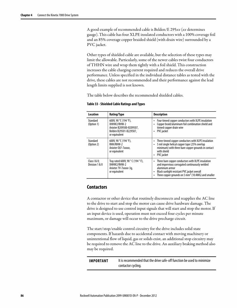
Chapter 4 Connect the Kinetix 7000 Drive System
A good example of recommended cable is Belden/E 295xx (xx determines gauge). This cable has four XLPE insulated conductors with a 100% coverage foil and an 85% coverage copper braided shield (with drain wire) surrounded by a PVC jacket.
Other types of shielded cable are available, but the selection of these types may limit the allowable. Particularly, some of the newer cables twist four conductors of THHN wire and wrap them tightly with a foil shield. This construction increases the cable charging current required and reduces the overall drive performance. Unless specified in the individual distance tables as tested with the drive, these cables are not recommended and their performance against the lead length limits supplied is not known.
The table below describes the recommended shielded cables.
Table 33 - Shielded Cable Ratings and Types
Contactors
A contactor or other device that routinely disconnects and reapplies the AC line to the drive to start and stop the motor can cause drive hardware damage. The drive is designed to use control input signals that will start and stop the motor. If an input device is used, operation must not exceed four cycles per minute maximum, or damage will occur to the drive precharge circuit.
The start/stop/enable control circuitry for the drive includes solid state components. If hazards due to accidental contact with moving machinery or unintentional flow of liquid, gas or solids exist, an additional stop circuitry may be required to remove the AC line to the drive. An auxiliary braking method also may be required.
Location Rating/Type Description
Standard (Option 1)
600V, 90 °C (194 °F), XHHW2/RHW-2 Anixter B209500-B209507, Belden B29501-B229507, or equivalent
• Four tinned copper conductors with XLPE insulation• Copper braid/aluminum foil combination shield and
tinned copper drain wire• PVC jacket
Standard (Option 2)
600V, 90 °C (194 °F), RHH/RHW-2 Anixter OLF-7xxxxx, or equivalent
• Three tinned copper conductors with XLPE insulation• 5 mil single helical copper tape (25% overlap
minimum) with three bare copper grounds in contact with shield
• PVC jacket
Class I & II;Division 1 & II
Tray rated 600V, 90 ° C (194 ° F), XHHW2/RHW-2 Anixter 7V-7xxxxx-3g, or equivalent
• Three bare copper conductors with XLPE insulation and impervious corrugated continuously welded aluminum armor
• Black sunlight resistant PVC jacket overall• Three copper grounds on 5 mm2 (10 AWG) and smaller
IMPORTANT It is recommended that the drive safe-off function be used to minimize contactor cycling.
86 Rockwell Automation Publication 2099-UM001D-EN-P - December 2012

Connect the Kinetix 7000 Drive System Chapter 4
Power Wire Specifications
Wire should be copper with 75 °C (167 °F) minimum rating. Phasing of main AC power is arbitrary and earth ground connection is required for safe and proper operation.
For additional information see Power Specifications on page 150, and Interconnect Diagram Notes on page 162 for interconnect diagrams.
ATTENTION: This drive contains ESD (Electrostatic Discharge) sensitive parts and assemblies. You are required to follow static control precautions when you install, test, service, or repair this assembly. If you do not follow ESD control procedures, components can be damaged. If you are not familiar with static control procedures.See publication 8000-4.5.2, Guarding Against Electrostatic Damage or any other applicable ESD protection handbook.
ATTENTION: To avoid personal injury and/or equipment damage, be sure the installation complies with specifications regarding wire types, conductor sizes, branch circuit protection, and disconnect devices. The National Electrical Code (NEC) and local codes outline provisions for safely installing electrical equipmentTo avoid personal injury and/or equipment damage, be sure the motor power connectors are used for connection purposes only. Do not use them to turn the unit on and off.To avoid personal injury and/or equipment damage, be sure the shielded power cables are grounded to prevent potentially high voltages on the shield.
Rockwell Automation Publication 2099-UM001D-EN-P - December 2012 87

Chapter 4 Connect the Kinetix 7000 Drive System
Power Wiring Guidelines Use these guidelines when wiring the power connectors on your Kinetix 7000 drive (without a LIM).
This procedure assumes you have separate power supply/line filter components mounted on your panel and are ready to wire the AC input power to the drive.
1. Prepare the wires for attachment to each connector by removing insulation equal to an acceptable strip length.
The actual strip length will vary based on the wire gauge and terminal size of the Kinetix 7000 drive.
2. Route the wires to your Kinetix 7000 drive.
3. Insert the wires into the connector or connect the wires to the terminals.
4. Tighten the terminal screws/nuts to the recommended torque for the specific terminal.
5. Pull on each wire to make sure it does not come out of its terminal. If any wires are loose, reinsert/connect and tighten the wire to the recommended torque.
Wire the Kinetix 7000 Drive Connectors
See Appendix B for all Kinetix 7000 drive interconnect diagrams.
Wire the Control Power (CP) Connector
Wire the 24V DC control power supply to your Kinetix 7000 drive as described in Table 34. See Control Power (CP) Terminal Block Connections for more information.
Table 34 - Control Power Connections
IMPORTANT To achieve system performance, run wires and cables in the wireways as established in Chapter 1.
IMPORTANT To limit coil switching transients generated by the LINE contactor, use of a surge suppressor is recommended. For an example, see Appendix B.
Signal Terminal Recommended Wire Sizemm2 (AWG)
Strip Lengthmm2 (in.)
Torque N•m (lb•in)
CP_24VDC 1 0.75 (18)(stranded wire with ferrule)1.5 (16)(solid wire)
7.0 (0.275) 0.235 (2.0)CP_COM 2
88 Rockwell Automation Publication 2099-UM001D-EN-P - December 2012

Connect the Kinetix 7000 Drive System Chapter 4
Wire AC Input Power
Wire 460V AC input power to your Kinetix 7000 drive as described in Table 35. See Power Terminal Block (PTB) Connections for more information.
Table 35 - AC Input Power Connections
Wire DC Input Power (Common Bus Configurations Only)
Wire the DC input power from a leader regenerative power supply (8720MC-RPS) to a Kinetix 7000 drive as described in Table 36. See Power Terminal Block (PTB) Connections on page 51 for more information.
Kinetix 7000 Drive Cat. No.
Signal Terminal Recommended Wire Sizemm2 (AWG)
Torque N•m (lb•in)
2099-BM06-S2099-BM07-S2099-BM08-S
L1L2L3Ground
RSTPE
25…2.5 (3…14) 1.8 (16)
2099-BM09-S L1L2L3
RST
50…4 (1/0…12) 3.6 (32)
Ground PE 50…4 (1/0…12) 5 (44)
2099-BM10-S L1L2L3
RST
70…10 (2/0…8) 15 (133)
Ground PE 50…4 (1/0…12) 5 (44)
2099-BM11-S2099-BM12-S
L1L2L3
RST
100…10 (4/0…8) 12 (104)
Ground PE 50…4 (1/0…12) 5 (44)
IMPORTANT DC power from the regenerative power supply (8720MC-RPS) is typically routed to a power distribution box. Fusing will be placed before and after the distribution box, providing protection for both the 8720MC-RPS and Kinetix 7000 drive.
Rockwell Automation Publication 2099-UM001D-EN-P - December 2012 89
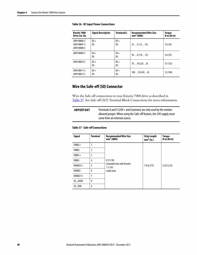
Chapter 4 Connect the Kinetix 7000 Drive System
Table 36 - DC Input Power Connections
Wire the Safe-off (SO) Connector
Wire the Safe-off connections to your Kinetix 7000 drive as described in Table 37. See Safe-off (SO) Terminal Block Connections for more information.
Table 37 - Safe-off Connections
Kinetix 7000 Drive Cat. No.
Signal Description Terminal(s) Recommended Wire Sizemm2 (AWG)
Torque N•m (lb•in)
2099-BM06-S2099-BM07-S2099-BM08-S
DC+DC-
DC+DC- 25…2.5 (3…14) 1.8 (16)
2099-BM09-S DC+DC-
DC+DC-
50…4 (1/0…12) 3.6 (32)
2099-BM10-S DC+DC-
DC+DC-
70…10 (2/0…8) 15 (133)
2099-BM11-S2099-BM12-S
DC+DC-
DC+DC-
100…10 (4/0…8) 12 (104)
IMPORTANT Terminals 8 and 9 (24V+ and Common) are only used by the motion-allowed jumper. When using the Safe-off feature, the 24V supply must come from an external source.
Signal Terminal Recommended Wire Sizemm2 (AWG)
Strip Lengthmm2 (in.)
Torque N•m (lb•in)
FDBK2+ 1
0.75 (18)(stranded wire with ferrule)1.5 (16)(solid wire)
7.0 (0.275) 0.235 (2.0)
FDBK2- 2
FDBK1+ 3
FDBK1- 4
ENABLE2+ 5
ENABLE- 6
ENABLE1+ 7
SO_24VDC 8
SO_COM 9
90 Rockwell Automation Publication 2099-UM001D-EN-P - December 2012

Connect the Kinetix 7000 Drive System Chapter 4
Wire the General Purpose Relay (GPR) and General Purpose I/O (GPIO) Connectors
Wire the control and interface signals on the General Purpose Relay (GPR) and General Purpose I/O (GPIO) connectors as described in Table 38 and Table 39. See General Purpose I/O (GPIO) Terminal Block Connections on page 46 and General Purpose Relay (GPR) Terminal Block Connections on page 46 for more information.
Table 38 - General Purpose Relay Connections
Table 39 - General Purpose I/O Connections
ATTENTION: Wiring the DRIVE OK signal on the General Purpose Relay is required. To avoid injury or damage to the drive, wire the DRIVE OK relay into your safety control string.In common bus configurations, a REGEN connection on the General Purpose Input/Output connector is also required for the drives. This connection must be wired in series to the safety control string, and also wired from the 8720MC-RPS to the Kinetix 7000 drive to indicate bus voltage is present.
Signal Terminal Description Recommended Wire Sizemm2 (AWG)
Strip Lengthmm (in.)
Torque ValueN•m (lb•in)
DRIVE OK+ 5 Programmable N.O. Relay 2 output 0.75 (18)(stranded wire with ferrule)1.5 (16)(solid wire)
7.0 (0.275) 0.235 (2.0)DRIVE OK- 6 Programmable Relay 2 common
Signal Terminal Description Recommended Wire Sizemm2 (AWG)
Strip Lengthmm (in.)
Torque ValueN•m (lb•in)
Regen_OK+ 7 Regenerative power supply status 0.75 (18)(stranded wire with ferrule)1.5 (16)(solid wire)
7.0 (0.275) 0.235 (2.0)Regen_OK- 8 Regenerative power supply status common
Rockwell Automation Publication 2099-UM001D-EN-P - December 2012 91

Chapter 4 Connect the Kinetix 7000 Drive System
Wire Motor Output Power
Wire motor output power as described in Table 40. See Power Terminal Block (PTB) Connections on page 51 for more information.
Table 40 - HPK-Series and MP-Series Servo Motor Power Connections
Wire the Motor Brake
Wire the motor brake (if applicable) as described in Table 41. See Power Terminal Block (PTB) Connections on page 51 for more information on the motor power connections.
Table 41 - Motor Brake Connections
Notes: HPK-Series motor brake terminations are BR+ and BR-. RDD-Series motors do not have a motor brake.
Kinetix 7000 Drive Cat. No.
Signal Terminal Recommended Wire Sizemm2 (AWG)
Torque N•m (lb•in)
2099-BM06-S2099-BM07-S2099-BM08-S
U / BrownV / Blackw / Blue
Green/Yellow
UVW 25…2.5 (3…14) 1.8 (16)
2099-BM09-S U / BrownV / Blackw / Blue
UVW
50…4 (1/0…12) 3.6 (32)
Green/Yellow 50…4 (1/0…12) 5 (44)
2099-BM10-S U / BrownV / Blackw / Blue
UVW
70…10 (2/0…8) 15 (133)
Green/Yellow 50…4 (1/0…12) 5 (44)
2099-BM11-S2099-BM12-S
U / BrownV / Blackw / Blue
UVW
100…10 (4/0…8) 12 (104)
Green/Yellow 50…4 (1/0…12) 5 (44)
IMPORTANT Use surge suppression when controlling a brake coil.See Figure 81 on page 172.
Motor Brake Terminal (Signal) Drive Terminal (Signal)
Recommended Wire Sizemm2 (AWG)
Strip Lengthmm (in.)
Torque ValueN•m (lb•in)Bulletin MPL
w/Bayonet ConnectorBulletin MPx w/Circular DIN Connector
A (BR+) F (BR+) 2 (GPR1+)2.5 (14) 10 (0.38)
0.5…0.6(4.4…5.3)C (BR-) G (BR-) 3 (GPR1-)
92 Rockwell Automation Publication 2099-UM001D-EN-P - December 2012

Connect the Kinetix 7000 Drive System Chapter 4
Motor brake wiring varies slightly, depending on the motor connector type. The table below identifies the brake wire option for your servo motor and the appropriate brake cable or connector kit catalog number required.
Feedback and I/O Cable Connections
Factory-made cables with premolded connectors are designed to minimize EMI and are recommended over hand-built cables to improve system performance. However, other options are available for building your own feedback and I/O cables.
Table 42 - Motor Feedback Cable Compatibility - Bayonet Connectors
Table 43 - Motor Feedback Cable Compatibility - Circular DIN Connectors
Motor Series Connector Type
Brake Wire Option Cable Cat. No.
Bulletin MPL Circular DIN The brake terminals are in the motor power connector. Drive to motor power cables must be ordered with the brake option.
2090-CPBM7DF-xxAAxx (1)
2090-XXNPMF-xxSxx (standard, non-flex)2090-CPBMxDF-xxAFxx (1)
(continuous-flex)
Bayonet The motor has a separate brake connector and requires a brake power cable.
2090-UXxBMP-18Sxx brake cable (2)
Bulletin MPM Circular DIN The brake terminals are in the motor power connector. Drive to motor power cables must be ordered with the brake option.
2090-CPBM7DF-xxAAxx (1)
2090-XXNPMF-xxSxx(standard, non-flex)2090-CPBMxDF-xxAFxx (1)
(continuous-flex)
HPK-Series N/A The motor has a separate brake wiring connection.
Customer-supplied
(1) You must remove the motor-side o-ring when using 2090-CPxM7DF-xxAxxx cables.(2) For Bulletin MPL motors equipped with bayonet connectors. These cables are available as standard, non-flex (catalog number 2090-
UXNBMP-18Sxx) and continuous-flex (catalog number 2090-UXTBMP-18Sxx).
Motor/Actuator Connector Type Feedback Type
Feedback Cable
Premolded Flying-lead
MPL-Bxxxx-S Bayonet High-resolution encoder 2090-UXNFBMP-Sxx 2090-XXxFMP-Sxx (1)
(1) For Bulletin MPL and 1326AB (M2L/S2L) motors equipped with bayonet connectors. These cables are available as standard, non-flex (catalog number 2090-XXNFMP-Sxx) and continuous-flex (catalog number 2090-XXTFMP-Sxx).
Motor/Actuator Connector Type Feedback Type
Feedback Cable (1)
(1) You must remove the motor-side o-ring when using 2090-CFBM7xx-xxAxxx cables.
Premolded Flying-lead
MPL-B5xxx-S/Mx7xAA,MPL-B6xxx-S/Mx7xAA,MPL-B8xxx-S/Mx7xAAMPL-B9xxx-S/Mx7xAA
SpeedTec DIN High-resolution encoder
2090-CFBM7DD-CEAAxx(standard, non-flex) or2090-CFBM7DD-CEAFxx(continuous-flex)
2090-CFBM7DF-CEAAxx(standard, non-flex) or2090-CFBM7DF-CEAFxx (continuous-flex)
MPM-Bxxxxx-S/M
RDB-Bxxxx-7/3
N/A
2090-XXNFMF-Sxx (standard, non-flex) or2090-CFBM7DF-CDAFxx (continuous-flex)
HPK-Series
2090-XXNFMF-Sxx(standard, non-flex)2090-CFBM4DF-CDAFxx(continuous-flex)
Rockwell Automation Publication 2099-UM001D-EN-P - December 2012 93
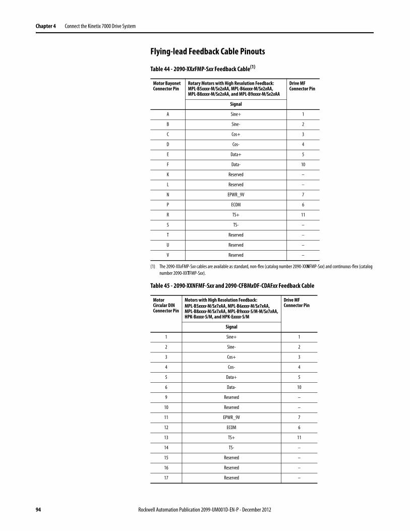
Chapter 4 Connect the Kinetix 7000 Drive System
Flying-lead Feedback Cable Pinouts
Table 44 - 2090-XXxFMP-Sxx Feedback Cable(1)
(1) The 2090-XXxFMP-Sxx cables are available as standard, non-flex (catalog number 2090-XXNFMP-Sxx) and continuous-flex (catalog number 2090-XXTFMP-Sxx).
Table 45 - 2090-XXNFMF-Sxx and 2090-CFBMxDF-CDAFxx Feedback Cable
Motor Bayonet Connector Pin
Rotary Motors with High Resolution Feedback:MPL-B5xxxx-M/Sx2xAA, MPL-B6xxxx-M/Sx2xAA,MPL-B8xxxx-M/Sx2xAA, and MPL-B9xxxx-M/Sx2xAA
Drive MF Connector Pin
Signal
A Sine+ 1
B Sine- 2
C Cos+ 3
D Cos- 4
E Data+ 5
F Data- 10
K Reserved –
L Reserved –
N EPWR_9V 7
P ECOM 6
R TS+ 11
S TS- –
T Reserved –
U Reserved –
V Reserved –
Motor Circular DIN Connector Pin
Motors with High Resolution Feedback:MPL-B5xxxx-M/Sx7xAA, MPL-B6xxxx-M/Sx7xAA,MPL-B8xxxx-M/Sx7xAA, MPL-B9xxxx-S/M-M/Sx7xAA,HPK-Bxxxx-S/M, and HPK-Exxxx-S/M
Drive MF Connector Pin
Signal
1 Sine+ 1
2 Sine- 2
3 Cos+ 3
4 Cos- 4
5 Data+ 5
6 Data- 10
9 Reserved –
10 Reserved –
11 EPWR_9V 7
12 ECOM 6
13 TS+ 11
14 TS- –
15 Reserved –
16 Reserved –
17 Reserved –
94 Rockwell Automation Publication 2099-UM001D-EN-P - December 2012

Connect the Kinetix 7000 Drive System Chapter 4
Table 46 - 2090-XXNFMF-Sxx and 2090-CFBMxDF-CDAFxx Feedback Cable
Wire Feedback and I/O Connectors
Wire your feedback and I/O cables.
Connect Premolded Motor Feedback Cables
Motor feedback cables (with premolded connectors) plug directly into 15-pin motor feedback (MF) connectors on Kinetix 7000 drive (no wiring is necessary).
Motor Circular DIN Connector Pin
RDB-Bxxxxx-3/7 Motors 2090-K7CK-KENDAT Pin
Signal
1 Sine+ 1
2 Sine- 2
3 Cos+ 3
4 Cos- 4
5 Data+ 9
6 Data- 10
7 CLK+ 7
8 CLK- 8
9 EPWR_5V 5
10 ECOM 6
11 Reserved –
12 Reserved –
13 TS+ 11
14 TS- –
15 Reserved –
16 Reserved –
17 Reserved –
To make this type of connection Go to
Premolded Cable Connect Premolded Motor Feedback Cables below.
Panel-mounted Breakout Board Wire Panel-mounted Breakout Board Kits on page 96.
Low-profile Connector Wire Low-profile Connectors on page 98.
IMPORTANT When using Bulletin 2090 cables with premolded connectors, tighten the mounting screws (finger tight) to improve system performance.
Rockwell Automation Publication 2099-UM001D-EN-P - December 2012 95
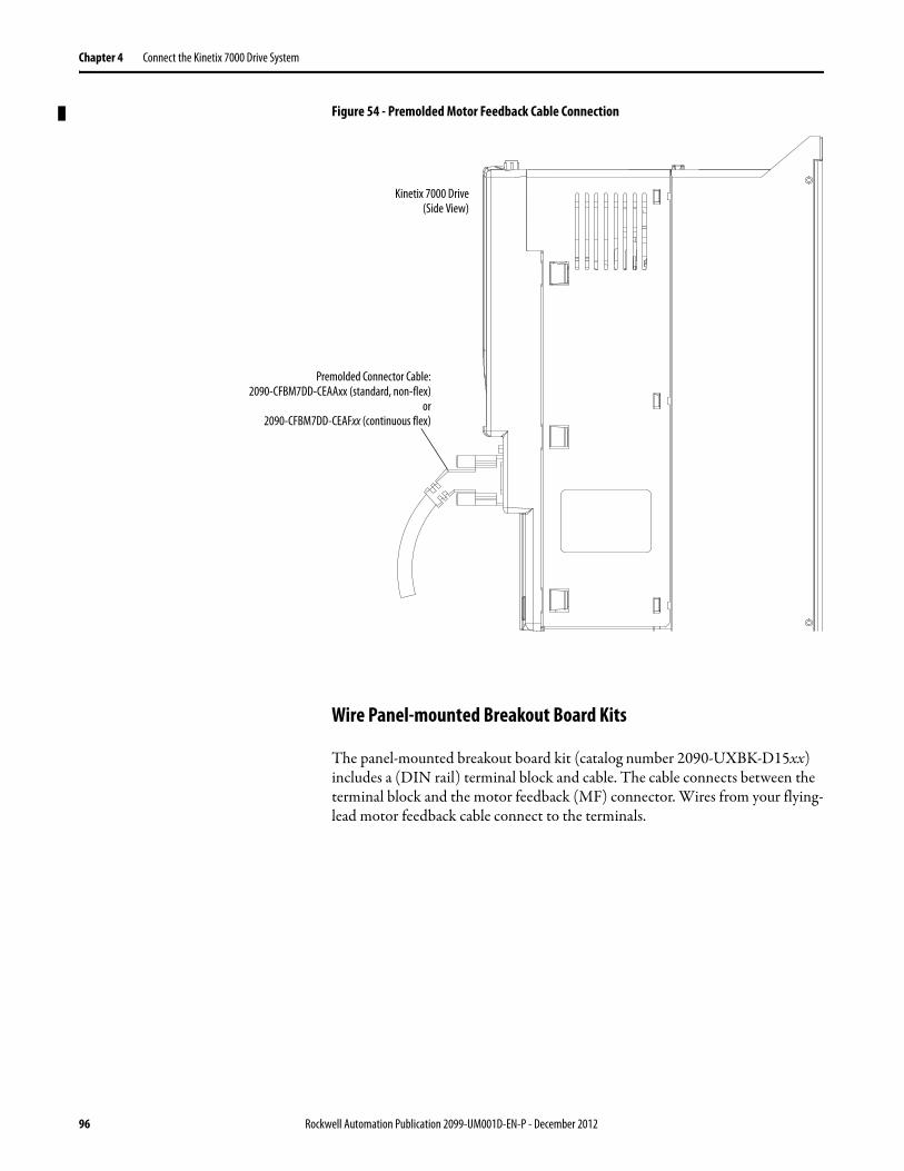
Chapter 4 Connect the Kinetix 7000 Drive System
Figure 54 - Premolded Motor Feedback Cable Connection
Wire Panel-mounted Breakout Board Kits
The panel-mounted breakout board kit (catalog number 2090-UXBK-D15xx) includes a (DIN rail) terminal block and cable. The cable connects between the terminal block and the motor feedback (MF) connector. Wires from your flying-lead motor feedback cable connect to the terminals.
Premolded Connector Cable:2090-CFBM7DD-CEAAxx (standard, non-flex)
or2090-CFBM7DD-CEAFxx (continuous flex)
Kinetix 7000 Drive(Side View)
96 Rockwell Automation Publication 2099-UM001D-EN-P - December 2012

Connect the Kinetix 7000 Drive System Chapter 4
Figure 55 - Panel-mounted Breakout Board Connection Example
2090-UXBC-D15xxBreakout Cable
See the Motor Feedback Breakout BoardInstallation Instructions, publication 2090-IN006,for Connector Breakout Board Specifications.
Kinetix 7000 Drive(Side View)
2090-UXBB-D15xxPanel-mounted Breakout Board
Rockwell Automation Publication 2099-UM001D-EN-P - December 2012 97

Chapter 4 Connect the Kinetix 7000 Drive System
Wire Low-profile Connectors
Low-profile connectors (2090-K6CK-Dxxx) are suitable for motor feedback (MF), auxiliary feedback (AF), and I/O connections (IOD) on Kinetix 7000 drive.
Table 47 - Low-profile Connector Kits
Connector KitCat. No.
Description Cable Compatibility
2090-K7CK-KENDAT Low-profile feedback module for connecting to Heidenhain EnDat high-resolution feedback device (15-pin, male, D-sub). Use with any Kinetix 7000 drive and Bulletin RDB direct-drive motor with EnDat high-resolution feedback.NOTE: Only 2099-BMxx-S drives with firmware revision 1.104 or higher support the use of this feedback module.
2090-XXxFMP-Sxx,2090-XXNFMF-Sxx,2090-CFBMxDF-CxAxxx
2090-K6CK-D15M Low-profile connector kit for motor feedback (15-pin, male, D-sub). Use with any Kinetix 7000 drive and compatible motors.
2090-K6CK-D15F Low-profile connector kit for auxiliary feedback (15-pin, female, D-sub). Use with any Kinetix 7000 drive for auxiliary feedback applications.
Customer supplied
2090-K6CK-D26M Low-profile connector kit for I/O (26-pin, male, D-sub). Use with any Kinetix 7000 drive or 2094-BL02 LIM module for making I/O connections.
2090-Kxxx-DxxxLow-profile Connector Kit
with Flying-lead Feedback orI/O Cable
Kinetix 7000 Drive(Side View)
IMPORTANT Tightening the mounting screws is essential to be sure of shield integrity between the low-profile connector covers and the drive feedback connector D-shells. Tightening torque is 0.4 N•m (35 lb•in).
98 Rockwell Automation Publication 2099-UM001D-EN-P - December 2012

Connect the Kinetix 7000 Drive System Chapter 4
Figure 56 - Wiring (15-pin) Flying-lead Feedback Cable Connections2090-K6CK-D15M and 2090-K6CK-D15F Connector Kits
Figure 57 - Wiring (15-pin) Flying-lead Feedback Cable Connections2090-K7CK-KENDAT Feedback Module
Pin 1 Pin 11
Pin 10Pin 5
Pin 6
Pin 15Pin 1
Pin 10Pin 5
Pin 11Pin 6
Pin 15
12
34
56
78
910
1112
1314
150
15-pin (male) Motor FeedbackLow-profile Connector
15-pin (female) Auxiliary FeedbackLow-profile Connector
See page 66 for Feedback Signal Descriptions.
See Appendix B for the Motor Feedback Interconnect Drawing for Your Application.
TieWrap
Exposed Braid Under Clamp
Bulletin 2090 Feedback Cable
Shield Clamp
Outer insulation
Braided shield
Foil shieldWire insulation
Bare wires
Bulletin 2090Feedback Cable
Turn Clamp Over to HoldSmall Wires Secure
MountingScrews
See the Low Profile Connector Kit Installation Instructions, Publication2094-IN007, for Connector Kit Specifications.
2090-K6CK-D15xLow-profile Connector Kit
Pin 1
Pin 10Pin 5
Pin 11Pin 6
Pin 15
67
89
1011
1213
12
34
5
15-pin (male) Motor FeedbackLow-profile Connector
See page 66 for Feedback Signal Descriptions.
Exposed Braid Under Clamp
Shield Clamp
Outer Insulation
Braided Shield
Foil ShieldWire Insulation
Bare Wires
Turn Clamp Over to HoldSmall Wires Secure.
MountingScrews
See Appendix B for the Motor Feedback Interconnect Drawing for Your Application.
2090-K7CK-KENDATLow-profile Feedback Module
Bulletin 2090 Feedback Cable
Bulletin 2090Feedback Cable
StatusIndicator
See the Low Profile Connector Kit Installation Instructions, Publication2094-IN007, for Connector Lit Specifications.
IMPORTANT The purpose of the cable shield clamp is to provide a proper ground and improve system performance, not stress relief.Clamping the exposed braid under the shield clamp is critical. Turn the clamp over, if necessary, to be sure of a proper ground.
Rockwell Automation Publication 2099-UM001D-EN-P - December 2012 99

Chapter 4 Connect the Kinetix 7000 Drive System
Figure 58 - Wiring (26-pin) I/O Cable Connections2090-K6CK-D26M Connector Kit
Pin 18
Pin 26
Pin 1
Pin 9
Pin 10Pin 19
1314
1516
1718
1920
2122
23S
2425
26S
101112
12
34
56
78
9
26-pin (male) I/OLow-profile Connector
Discrete I/O Wire
Tie Wrap Slot
Three ConductorI/O Cable(s)
Turn Clamp Over to Hold Small Wires
Secure
MountingScrews
See the Low Profile Connector Kit Installation Instructions, Publication2094-IN007, for Connector Kit Specifications.
2090-K6CK-D26MLow-profile Connector Kit
IMPORTANT The purpose of the cable shield clamp is to provide a proper ground and improve system performance, not stress relief.Clamping the exposed braid under the shield clamp is critical. Turn the clamp over, if necessary, to be sure of a proper ground.
100 Rockwell Automation Publication 2099-UM001D-EN-P - December 2012

Connect the Kinetix 7000 Drive System Chapter 4
External Shunt Module Connections
External active shunt modules listed in the table on page 156 are compatible with Kinetix 7000 drives. Follow these guidelines when wiring your external active shunt module kit.
• Refer to Shunt Resistor on page 37 for important wiring recommendations.
• Refer to Appendix B for the Kinetix 7000 drive interconnect diagrams.
• Refer to the installation instructions provided with your shunt module.
SERCOS Fiber-optic Cable Connections
This procedure assumes you have your Logix SERCOS interface module/PCI card and Kinetix 7000 drive mounted and are ready to connect the fiber-optic cables.
The SERCOS fiber-optic ring is connected using the SERCOS receive (Rx) and transmit (Tx) connectors.
See page 65 to locate the SERCOS connectors on your Kinetix 7000 drive. See the figure below to locate the connectors on your SERCOS interface module or PCI card.
Plastic cable is available in lengths up to 32 m (105 ft). Glass cable is available in lengths between 50 m (164 ft) and 200 m (656 ft).
IMPORTANT When tightening screws to secure the wires to the DC bus terminals, see Table 36 on page 90 for torque values.
IMPORTANT When connecting Kinetix 7000 drives, use at least a 2090-SCEP1-0, 1 m (3 ft) or longer cable.Larger drives may require longer cables.
Rockwell Automation Publication 2099-UM001D-EN-P - December 2012 101

Chapter 4 Connect the Kinetix 7000 Drive System
Figure 59 - CompactLogix, ControlLogix, and SoftLogix SERCOS Connector Locations
Connect the cable from transmit on the Logix module to receive on the Kinetix 7000 drive, then transmit to receive (drive to drive), and from transmit on the last drive back to receive on the Logix module.
Figure 60 - Fiber-optic Cable Connections to a SoftLogix Module
SERCOS interfaceTM
Tx (rear)
Rx (front)
OKCP
0
8
4
C 675
321
9AB
ED F
TX
RX
OK
CP
Tx (rear)
Rx (front)
RSLogix 5000 Software
ControlLogix Platform1756-MxxSE SERCOSinterface Module
SERCOS Receive Connector, Rx (front)
SERCOS Transmit Connector, Tx (rear)
Front View
Bottom View
SoftLogix Platform1756-PM16SE SERCOS interface PCI Card(as viewed from the back of your personal computer)
SERCOS Receive Connector, Rx
SERCOS Transmit Connector, Tx
Front View
CompactLogix Platform1768-M04SE SERCOS
interface Module
ATTENTION: To avoid damage to the SERCOS Rx and Tx connectors use only finger-tight torque when attaching the fiber-optic cables to the Kinetix 7000 drive. Do not use a wrench or any other mechanical assistance.
For more information, see the Fiber-optic Cable Installation and Handling Instructions, publication 2090-IN010.
0
8
4
C 675
3
219AB
ED
F
TX
RX
OK
CP
ReceiveTransmit
SoftLogix1784-PM16SE SERCOSinterface PCI Card
Kinetix 6000 System
Receive Transmit
SERCOS Fiber-optic Ring
Kinetix 7000 Drive
TransmitReceive
102 Rockwell Automation Publication 2099-UM001D-EN-P - December 2012

Connect the Kinetix 7000 Drive System Chapter 4
The following fiber-optic cable examples are shown using ControlLogix modules. CompactLogix modules connect in the same way, however the ring cannot include more than four drives.
Figure 61 - Fiber-optic Cable Connections to ControlLogix/CompactLogix Modules
You can also mount the two Logix SERCOS modules in two separate chassis, or you can mount them in the same chassis.
SERCOS interface TM
Tx (rear)
Rx (front)
OKCP
Kinetix 6000 System
1756-MxxSE SERCOS interface Module
Receive
Receive
Transmit
Transmit
SERCOS Fiber-optic Ring
Kinetix 7000 Drive System
TransmitReceive
Logix Chassis(ControlLogix is shown)
IMPORTANT Clean the fiber-optic cable connectors prior to installation. Dust in the connectors can reduce signal strength.See the Fiber-optic Cable Installation and Handling Instructions, publication 2090-IN010, for more information.
Rockwell Automation Publication 2099-UM001D-EN-P - December 2012 103

Chapter 4 Connect the Kinetix 7000 Drive System
The following example depicts the second Kinetix system, consisting of Kinetix 7000 drives, located in a separate cabinet and connected with bulkhead adapters.
Figure 62 - Fiber-optic Cable Connections (ControlLogix/CompactLogix)
IMPORTANT To avoid signal loss, do not use bulkhead adapters to connect glass cables. Use bulkhead adapters for making plastic-to-plastic cable connections only.
SERCOS interface TM
Tx (rear)
Rx (front)
OKCP
1756-MxxSE SERCOSInterface Module
SERCOS Fiber-optic Ring SERCOS Ring
SERCOSFiber-optic Bulkhead Adapter
Kinetix 6000 System
Kinetix 7000 Drive System
Logix Chassis(ControlLogix is shown)
Receive
Receive
Transmit
Transmit
Receive
SERCOSFiber-optic Bulkhead Adapter
Transmit
104 Rockwell Automation Publication 2099-UM001D-EN-P - December 2012
Chapter 5
Configure and Startup the Kinetix 7000 Drive System
This chapter provides procedures for configuring your Kinetix 7000 system components with the Logix SERCOS module.
Before you begin, make sure you know the characteristics of the following system components.
• Logix processor• Logix module(s), including the SERCOS module• Kinetix 7000 drive(s) and accessories• Servo motor(s)/actuator(s)• transmission/load for the conversion constant
Topic Page
Configure the Drive Modules 106
Configure the Logix SERCOS interface Module 110
Apply Power to the Drive 126
Test and Tune the Axes 129
Configure Drive Parameters and System Variables 134
Rockwell Automation Publication 2099-UM001D-EN-P - December 2012 105

Chapter 5 Configure and Startup the Kinetix 7000 Drive System
Configure the Drive Modules Follow these steps to configure the Kinetix 7000 drive.
1. Verify that there is no power applied to the drive and that the SERCOS fiber-optic cables are plugged into the Tx and Rx connectors.
To verify your fiber-optic cable connections, refer to page 101.
2. Set the base node address for the drive by setting the SERCOS Node Address switch.
Valid node addresses are 01...99. The left hand switch sets the most significant digit (MSD) and the right hand switch sets the least significant digit (LSD).
Refer to the table and figure below for switch operation.
Table 48 - Node Addressing Switch Settings
Figure 63 - N ode Addressing Switch Settings
3. Cycle control power to initialize the drive.
4. Set the SERCOS communications rate using DIP switches 2 and 3.
To Press
Increment the (MSD/LSD) node address The plus (+) switch.
Decrement the (MSD/LSD) node address The minus (-) switch.
IMPORTANT When two or more drives are connected to the same SERCOS interface module, each node address must be unique.Refer to the node addressing examples beginning on page 108.
IMPORTANT The base node address setting takes effect only after the drive is initialized.
For This Communication Rate Set Switch 2 Set Switch 3
4 Mbps OFF ON
8 Mbps ON OFF
Decrements MSD
MSD
Increments MSD
Decrements LSD
LSD
Increments LSD
106 Rockwell Automation Publication 2099-UM001D-EN-P - December 2012
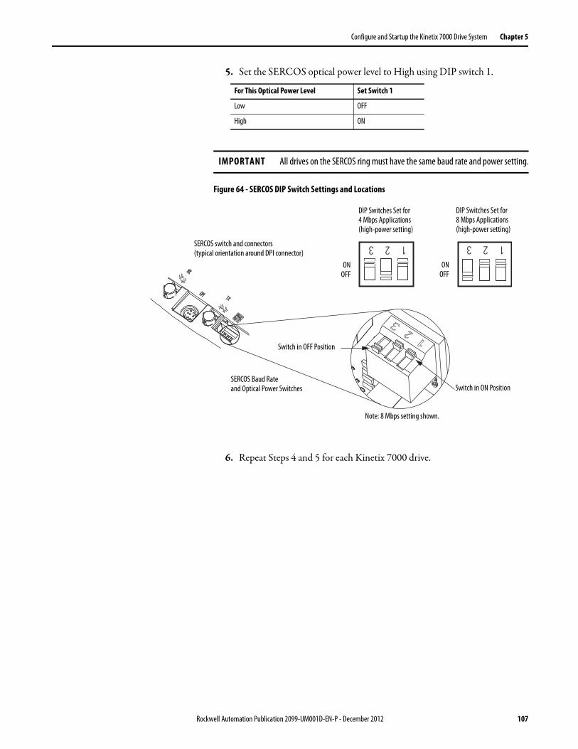
Configure and Startup the Kinetix 7000 Drive System Chapter 5
5. Set the SERCOS optical power level to High using DIP switch 1.
Figure 64 - SERCOS DIP Switch Settings and Locations
6. Repeat Steps 4 and 5 for each Kinetix 7000 drive.
For This Optical Power Level Set Switch 1
Low OFF
High ON
IMPORTANT All drives on the SERCOS ring must have the same baud rate and power setting.
1 2 3 1 2 3
DIP Switches Set for4 Mbps Applications(high-power setting)
DIP Switches Set for8 Mbps Applications(high-power setting)
ONOFF
SERCOS Baud Rateand Optical Power Switches
SERCOS switch and connectors(typical orientation around DPI connector)
ONOFF
Switch in ON Position
Switch in OFF Position
Note: 8 Mbps setting shown.
Rockwell Automation Publication 2099-UM001D-EN-P - December 2012 107

Chapter 5 Configure and Startup the Kinetix 7000 Drive System
Node Addressing Examples
The examples below illustrate how each axis in the fiber-optic ring is assigned a node address. The ControlLogix platform is used in the examples, but the node addressing is typical for Logix platforms.
Figure 65 - Node Addressing Example 1
In this example, SERCOS interface module 1 controls Kinetix 7000 axes 1 and 2. SERCOS interface module 2 controls Kinetix 7000 axis 3.
SERCOS interface TM
Tx (rear)
Rx (front)
OKCP
SERCOS interface TM
Tx (rear)
Rx (front)
OKCP
03 = Drive (axis 3) Node Address02 = Drive (axis 2) Node Address01 = Drive (axis 1) Base Node Address
SERCOS Fiber-optic Rings
1756-MxxSE SERCOSinterface Module 1
Kinetix 7000 Drive System
Transmit Receive
1756-MxxSE SERCOSinterface Module 2
Transmit Receive
Logix Chassis/PCI Card(ControlLogix chassis is shown)
Logix Chassis/PCI Card(ControlLogix chassis is shown)
Transmit
Receive Receive Transmit
TIP You can mount the two SERCOS interface modules in two separate Logix chassis (as shown above) or you can mount them in the same chassis.Utilizing two SERCOS interface modules to control axes from a single Kinetix 7000 drive lets you reduce cycle times.
108 Rockwell Automation Publication 2099-UM001D-EN-P - December 2012
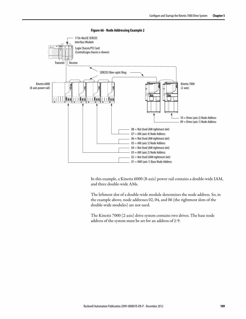
Configure and Startup the Kinetix 7000 Drive System Chapter 5
Figure 66 - Node Addressing Example 2
In this example, a Kinetix 6000 (8-axis) power rail contains a double-wide IAM, and three double-wide AMs.
The leftmost slot of a double-wide module determines the node address. So, in the example above, node addresses 02, 04, and 06 (the rightmost slots of the double-wide modules) are not used.
The Kinetix 7000 (2-axis) drive system contains two drives. The base node address of the system must be set for an address of ≥ 9.
SERCOS interface TM
Tx (rear)
Rx (front)
OKCP
08 = Not Used (AM rightmost slot) 07 = AM (axis 4) Node Address 06 = Not Used (AM rightmost slot) 05 = AM (axis 3) Node Address 04 = Not Used (AM rightmost slot) 03 = AM (axis 2) Node Address 02 = Not Used (IAM rightmost slot) 01 = IAM (axis 1) Base Node Address
SERCOS Fiber-optic Ring
1756-MxxSE SERCOSinterface Module
Kinetix 6000(8-axis power rail)
Transmit Receive
Logix Chassis/PCI Card(ControlLogix chassis is shown)
Kinetix 7000(2-axis)
10 = Drive (axis 2) Node Address 09 = Drive (axis 1) Node Address
Rockwell Automation Publication 2099-UM001D-EN-P - December 2012 109

Chapter 5 Configure and Startup the Kinetix 7000 Drive System
Configure the Logix SERCOS interface Module
This procedure assumes that you have wired your Kinetix 7000 system and set the Kinetix 7000 baud rate and optical power switches.
For resources on using RSLogix 5000 software as it applies to configuring the ControlLogix, CompactLogix, or SoftLogix SERCOS modules, refer to Additional Resources on page 9.
Configure the Logix Controller
Follow these steps to configure the Logix controller.
1. Apply power to your Logix chassis containing the SERCOS interface module and open your RSLogix 5000 software.
2. From the File menu, choose New.
The New Controller dialog box opens.
3. Configure the controller.a. From the Type pull-down menu, choose the controller type.b. From the Revision pull-down menu, choose the revision.c. Type the file Name.d. From the Chassis Type pull-down menu, choose the chassis.e. Choose the Logix processor Slot.
4. Click OK.
5. From the Edit menu, choose Controller Properties.
IMPORTANT For the Kinetix 7000 drive to communicate with the SERCOS interface module (indicated by three solid-green status indicators on the SERCOS module), your RSLogix 5000 software must be revision 15.0 or later.
110 Rockwell Automation Publication 2099-UM001D-EN-P - December 2012

Configure and Startup the Kinetix 7000 Drive System Chapter 5
The Controller Properties dialog box opens.
6. Click the Date/Time tab.
7. Check Enable Time Synchronization.
This assigns the controller as the Grandmaster clock. The motion modules set their clocks to the module you assign as the Grandmaster.
8. Click OK.
IMPORTANT You can assign only one module in the Logix chassis as the Grandmaster clock.
Rockwell Automation Publication 2099-UM001D-EN-P - December 2012 111

Chapter 5 Configure and Startup the Kinetix 7000 Drive System
Configure the SERCOS Module
Follow these steps to configure the SERCOS module.
1. Right-click on I/O Configuration in the Controller Organizer and choose New Module.
The Select Module dialog box opens.
2. Expand the Motion category and select 1756-MxxSE, 1756-L60M03SE, 1768-M04SE, or 1784-PM16SE as appropriate for your actual hardware configuration.
In this example, the 1756-M16SE module is selected.
3. Click OK.
The New Module dialog box opens.
4. Configure the module.a. Type the module Name.b. Enter the Logix SERCOS module slot (leftmost slot = 0).c. Check Open Module Properties.
5. Click OK.
112 Rockwell Automation Publication 2099-UM001D-EN-P - December 2012
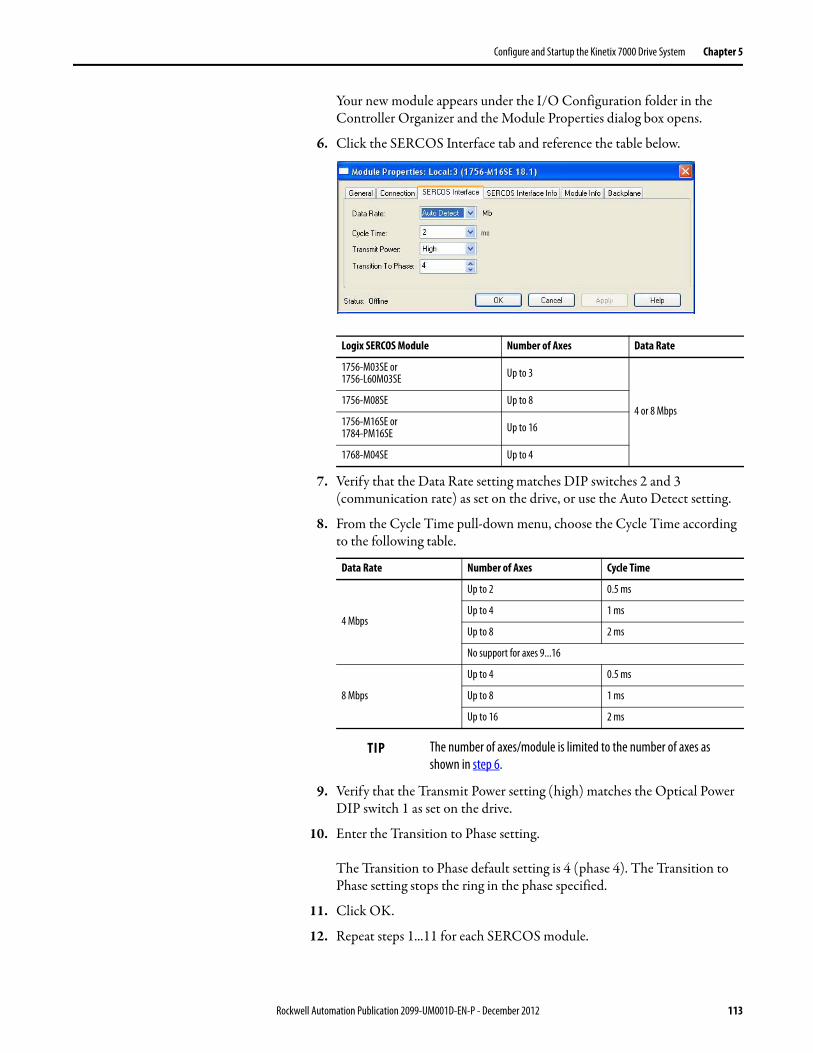
Configure and Startup the Kinetix 7000 Drive System Chapter 5
Your new module appears under the I/O Configuration folder in the Controller Organizer and the Module Properties dialog box opens.
6. Click the SERCOS Interface tab and reference the table below.
7. Verify that the Data Rate setting matches DIP switches 2 and 3 (communication rate) as set on the drive, or use the Auto Detect setting.
8. From the Cycle Time pull-down menu, choose the Cycle Time according to the following table.
9. Verify that the Transmit Power setting (high) matches the Optical Power DIP switch 1 as set on the drive.
10. Enter the Transition to Phase setting.
The Transition to Phase default setting is 4 (phase 4). The Transition to Phase setting stops the ring in the phase specified.
11. Click OK.
12. Repeat steps 1...11 for each SERCOS module.
Logix SERCOS Module Number of Axes Data Rate
1756-M03SE or 1756-L60M03SE Up to 3
4 or 8 Mbps1756-M08SE Up to 8
1756-M16SE or 1784-PM16SE Up to 16
1768-M04SE Up to 4
Data Rate Number of Axes Cycle Time
4 Mbps
Up to 2 0.5 ms
Up to 4 1 ms
Up to 8 2 ms
No support for axes 9...16
8 Mbps
Up to 4 0.5 ms
Up to 8 1 ms
Up to 16 2 ms
TIP The number of axes/module is limited to the number of axes as shown in step 6.
Rockwell Automation Publication 2099-UM001D-EN-P - December 2012 113

Chapter 5 Configure and Startup the Kinetix 7000 Drive System
Configure the Motion Group
Follow these steps to configure the motion group.
1. Right-click Motion Groups in the Controller Organizer and choose New Motion Group.
The New Tag dialog opens.
2. Type the new motion group Name.
3. Click OK.
The new motion group appears under the Motion Groups folder.
4. Right-click the new motion group and select Properties.
The Motion Group Properties dialog box opens.
114 Rockwell Automation Publication 2099-UM001D-EN-P - December 2012

Configure and Startup the Kinetix 7000 Drive System Chapter 5
No axis have been created yet. For this setup, a servo axis named Axis_1 and a feedback only axis named Axis_1_Aux will be created. Both axes will be assigned to the Kinetix 7000 axis in the Configure the Kinetix 7000 Drive Modules section.
5. Right-click the Motion group name created and select New Axis.
6. Select an Axis_Servo_Drive (SERCOS controlled axis).
The New Tag dialog opens.
7. Type Axis_1 (or the name of your axis) in the Name field. Axis_Servo_Drive is the correct Data Type.
8. Click Ok.
9. Repeat steps 5 and 6 above for the Axis_1_Aux Feedback Only axis.
10. Right-click on the Motion Group name created and select Properties.
Rockwell Automation Publication 2099-UM001D-EN-P - December 2012 115

Chapter 5 Configure and Startup the Kinetix 7000 Drive System
Both Axis_1 and Axis_1_Aux are Assigned to the Motion Group. This means both axis will be part of the SERCOS and Motion planner updates from/to the controller/SERCOS card/drive.
11. Open the Attribute folder.
The Motion Planner coarse update period must be set according to the application needs. Guidelines for the coarse update period for the processor used and the number of servo drive axes created in the motion group can be found in the following resources.• Rockwell Automation Knowledgebase at:
http://www.rockwellautomation.com/knowledgebase/• SERCOS and Analog Motion Configuration and Startup User
Manual, publication MOTION-UM001• The various Logix controller user manuals
Only 1 Motion group per processor is allowed.
12. Click Ok.
116 Rockwell Automation Publication 2099-UM001D-EN-P - December 2012
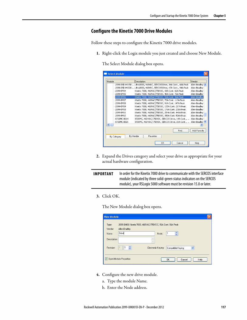
Configure and Startup the Kinetix 7000 Drive System Chapter 5
Configure the Kinetix 7000 Drive Modules
Follow these steps to configure the Kinetix 7000 drive modules.
1. Right-click the Logix module you just created and choose New Module.
The Select Module dialog box opens.
2. Expand the Drives category and select your drive as appropriate for your actual hardware configuration.
3. Click OK.
The New Module dialog box opens.
4. Configure the new drive module.a. Type the module Name.b. Enter the Node address.
IMPORTANT In order for the Kinetix 7000 drive to communicate with the SERCOS interface module (indicated by three solid-green status indicators on the SERCOS module), your RSLogix 5000 software must be revision 15.0 or later.
Rockwell Automation Publication 2099-UM001D-EN-P - December 2012 117

Chapter 5 Configure and Startup the Kinetix 7000 Drive System
Set the node address in the software to match the node setting on the drive. Refer to Configure the Drive Modules, step 2, on page 106.c. Check Open Module Properties.
5. Click OK.
6. Select the Associated Axes tab.
7. Assign Axis_1 to Node 1 in the Associated Axis folder. This assigns Axis 1 in the motion group to the Kinetix 7000 drive at node address 1. Select the Associated Axes tab.
8. Click Apply.
9. Click next to Axis_1.
The Axis Properties dialog box opens on the General tab.
10. Select the Units tab.
11. Select the correct position units to be used in your application. This example uses load millimeter.
118 Rockwell Automation Publication 2099-UM001D-EN-P - December 2012
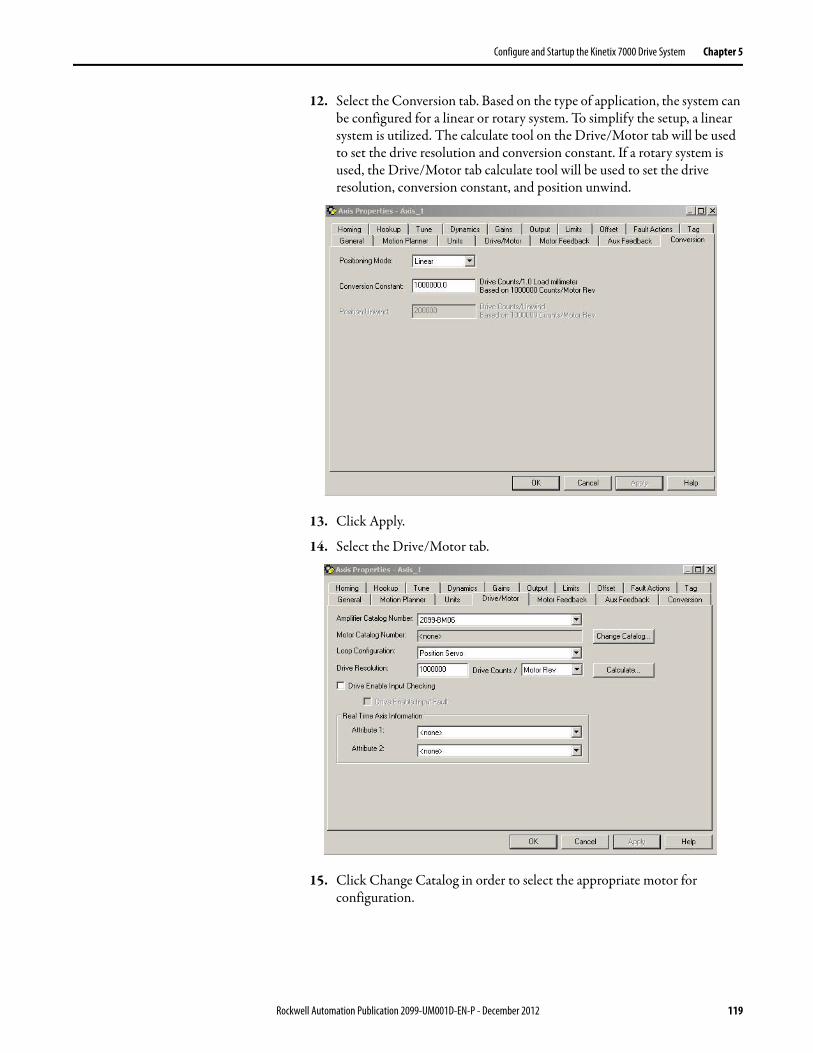
Configure and Startup the Kinetix 7000 Drive System Chapter 5
12. Select the Conversion tab. Based on the type of application, the system can be configured for a linear or rotary system. To simplify the setup, a linear system is utilized. The calculate tool on the Drive/Motor tab will be used to set the drive resolution and conversion constant. If a rotary system is used, the Drive/Motor tab calculate tool will be used to set the drive resolution, conversion constant, and position unwind.
13. Click Apply.
14. Select the Drive/Motor tab.
15. Click Change Catalog in order to select the appropriate motor for configuration.
Rockwell Automation Publication 2099-UM001D-EN-P - December 2012 119

Chapter 5 Configure and Startup the Kinetix 7000 Drive System
16. The Change Catalog Number dialog box appears.
17. Select the appropriate motor catalog number for your application. It is important to verify the motor catalog number on the motor nameplate as well as in your design specification.
18. Click OK.
19. Click Calculate, to configure the drive resolution and conversion constant. The position unwind is also calculated if rotary load is used.
20. In this example, a linear load is used and a 25.4 mm (1 in.) movement on a ballscrew is made with every 1 motor revolution. The total position movement on the ballscrew is 254 mm (9.8 in.).
21. Click Update.
22. Click Close.
23. The Drive Enable Input Checking is selected by default. When checked (default) a hard drive enable input signal on the IOD connector (pin 2) is required. Uncheck Drive Enable Input Checking if a hard drive enable input signal is not required.
120 Rockwell Automation Publication 2099-UM001D-EN-P - December 2012

Configure and Startup the Kinetix 7000 Drive System Chapter 5
The Drive/Motor tab and Conversion tabs should look similar to these examples or reflect your application configuration.
Rockwell Automation Publication 2099-UM001D-EN-P - December 2012 121
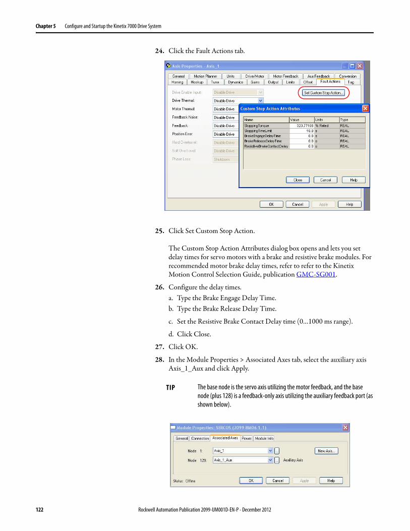
Chapter 5 Configure and Startup the Kinetix 7000 Drive System
24. Click the Fault Actions tab.
25. Click Set Custom Stop Action.
The Custom Stop Action Attributes dialog box opens and lets you set delay times for servo motors with a brake and resistive brake modules. For recommended motor brake delay times, refer to refer to the Kinetix Motion Control Selection Guide, publication GMC-SG001.
26. Configure the delay times.a. Type the Brake Engage Delay Time.b. Type the Brake Release Delay Time.
c. Set the Resistive Brake Contact Delay time (0…1000 ms range).
d. Click Close.
27. Click OK.
28. In the Module Properties > Associated Axes tab, select the auxiliary axis Axis_1_Aux and click Apply.
TIP The base node is the servo axis utilizing the motor feedback, and the base node (plus 128) is a feedback-only axis utilizing the auxiliary feedback port (as shown below).
122 Rockwell Automation Publication 2099-UM001D-EN-P - December 2012

Configure and Startup the Kinetix 7000 Drive System Chapter 5
Axis_1_Aux is configured similar to Axis_1, except that only a feedback device is configured.
29. Configure the Auxiliary Axis properties. Click next to Axis_1_Aux.
The Axis Properties dialog box opens on the General tab.
If an axis is associated to the auxiliary axis node, set the Axis Configuration on the General tab of the Axis Properties dialog box to Feedback Only.
30. Select the Units tab and configure the same as in steps 10…13 of this procedure.
31. Select the Conversion tab and configure the same as in steps 10…13 of this procedure.
32. Select the Drive/Motor tab.
The Drive/Motor tab displays the amplifier being used and the Loop Configuration is Aux Feedback Only. This is the only choice if the amplifier is using the primary node for Servo (motor) configuration.
Rockwell Automation Publication 2099-UM001D-EN-P - December 2012 123

Chapter 5 Configure and Startup the Kinetix 7000 Drive System
33. Configure the drive resolution / conversion constant (position unwind, if rotary) as in step 19…22 of this procedure.
34. Click the Aux Feedback tab.
35. From the Feedback Type pull-down menu, choose the feedback type appropriate for your auxiliary feedback motor.
36. Click Apply.
37. Click OK.
38. In the Module Properties, click the Power tab.
IMPORTANT The Aux Feedback tab must be configured for the auxiliary feedback type being used. In this example, an SRM feedback device is being used.
124 Rockwell Automation Publication 2099-UM001D-EN-P - December 2012

Configure and Startup the Kinetix 7000 Drive System Chapter 5
39. From the Bus Regulator Configuration pull-down menu, choose the component appropriate for your actual hardware configuration. Note: The Kinetix 7000 drive internal dynamic brake IGBT is not utilized by the drive main control for bus regulation therefore any type of regulation must come from an external source.
40. Click OK.
41. Repeat steps 1…27 for each additional axis.
42. Verify your Logix program and save the file.
Download the Program
After completing the Logix configuration you must download your program to the Logix processor.
If your drive requires Then choose
No bus regulator configuration <none>
External Shunt configuration 1336-MOD-KB005, KB010 or KB0501336-WB009, WB035 or WB110 (1)
(1) External shunt configuration 1336 MOD-KBxxx and 1336-WBxxx are no longer available for new sale but are selectable as of this manual release.
External regeneration power supply 8720MC-RPS027, 8720MC-RPS065, or 8720MC-RPS190 (2)(3)(4)
(2) 8720MC-RPSxxx is an external regenerative converter system used to regulate the DC bus connected to the Kinetix 7000 drive. Selecting this device will require the Kinetix 7000 drive GPIO terminal block pins 7 and 8 to be wired. See Figure 74 on page 165 for an example.
(3) 8720MC-RPS027BM-HV1 is no longer available for sale.(4) 8720MC-RPS065BM-HV1 has been superseded by 8720MC-RPS065BM-HV2.
Rockwell Automation Publication 2099-UM001D-EN-P - December 2012 125

Chapter 5 Configure and Startup the Kinetix 7000 Drive System
Apply Power to the Drive This procedure assumes that you have completed the following tasks:
• Wired your Kinetix 7000 drive.
• Connected your Logix controller, SERCOS interface module fiber-optic connections to your Kinetix 7000 drive.
• Configured and verified a RSLogix 5000 program.
• Connected the motor power and motor feedback cables to your Kinetix 7000 drive.
Refer to the Line Interface Module Installation Instructions, publication2094-IN005, when troubleshooting the LIM status indicators, and for the location of LIM circuit breakers, connectors, and status indicators.
Follow these steps to apply power to the Kinetix 7000 system.
1. Determine your source of control power.
2. Verify the status of the drive logic power status indicator.
SHOCK HAZARD: To avoid hazard of electrical shock, complete all mounting and wiring prior to applying power. Once power is applied, connector terminals may have voltage present even when not in use.
ATTENTION: To avoid personal injury or damage to equipment, disconnect the load to the motor. Make sure each motor is free of all linkages when initially applying power to the system.
If Your Control Power Then
Is sourced from a LIM module
1. Verify that the LIM CB1, CB2, and CB3 are in the OFF position.2. Apply three-phase input power to the LIM VAC Line connector.3. Set CB3 to the ON position.4. Set CB2 to the ON position.5. Go to main step 2.
Is not sourced from a LIM module
1. Apply 24V DC control power to the drive (CP connector).2. Go to main step 2.
If the Logic Power Status Indicator is Then
ON Go to step 3.
Not ON 1. Check your control power connections.2. Go back to main step 1.
Logic Power Status Indicator
Seven-segment Fault Status Indicator
126 Rockwell Automation Publication 2099-UM001D-EN-P - December 2012

Configure and Startup the Kinetix 7000 Drive System Chapter 5
3. Define the three-phase input power as described below.
4. Observe the seven-segment fault status indicator display on the drive.
The status indicator will first flash the SERCOS node address, then cycle through phases until final configuration (phase 4) is reached.
If Your Three-phase Power Then
Is sourced from a LIM module
1. Set the LIM CB1 to the ON position.2. Verify that the LIM, IPL, and OPL connections for phase-to-
phase voltage is 324…528V AC (460V).3. Verify that the input voltage at terminals R (L1), S (L2), and T
(L3) on the Kinetix 7000 drive is 324…528V AC (460V).4. If used, verify that the Kinetix 7000 drive Hardware Enable
Input signal (IOD pin 2) for each axis is off.5. Go to main step 4.
Is not sourced from a LIM module
1. Apply 324...528V AC (460V) input power to the Kinetix 7000 drive R (L1), S (L2), and T (L3) input terminals.
2. If used, verify that the Kinetix 7000 drive Hardware Enable Input signal (IOD pin 2) is off.
3. Go to main step 4.
Kinetix 7000 Drive Status Indicator Status Do This
Actively cycling (phase 0) The drive is looking for a closed SERCOS ring. Wait for phase 1 or take corrective action until you reach phase 1.
Check fiber-optic connections.
Displaying a fixed 1 (phase 1 The drive is looking for active nodes. Wait for phase 2 or take corrective action until you reach phase 2.
Check node addressing.
Displaying a fixed 2 (phase 2) The drive is configuring nodes for communication. Wait for phase 3 or take corrective action until you reach phase 3.
Check program motor and drive configuration against installed hardware.
Displaying a fixed 3 (phase 3) The drive is configuring device specific parameters. Wait for phase 4 or take corrective action until you reach phase 4.
Check motor catalog number against selection. (1)
Displaying a fixed 4 (phase 4) The drive is configured and active. Go to step 5.
Flashing an E followed by two numbers Drive is faulted. Go to Error Codes on page 138.
(1) To get diagnostic information from the module, highlight the module name in RSLogix 5000 software. A Pseudo Key Failure often indicates that the motor selection does not match the motor installed.
Rockwell Automation Publication 2099-UM001D-EN-P - December 2012 127

Chapter 5 Configure and Startup the Kinetix 7000 Drive System
5. Observe the three status indicators on the front of the drive.
6. Observe the three SERCOS status indicators on the SERCOS module.
Status Indicator Condition Status Do This
DriveOff Normal condition Observe the Comm status LED.
Steady red Drive is faulted Go to Status Indicators on page 143.
Comm
Flashing green Establishing communication with network Wait for steady green.
Steady green Communication is ready Observe the Bus status LED
Off No ring present Go to Interpret Error Codes and Status Indicators on page 138.
Bus
Steady green Axis is enabled when status should be disabled
1. Verify Hardware Enable Input (IOD-2) is open.2. Verify MSO instruction is not commanded in RSLogix 5000
software.3. Return to Apply Power to the Drive on page 126.
Flashing green (1) Bus is up, axis is disabled (normal status) Go to step 6.
Off DC bus is not present Go to Status Indicators on page 143.
(1) The follower drive has a 2.5 second delay after DC bus voltage is applied before the Bus Status LED begins flashing. This provides the common bus leader time to complete precharge.
SERCOS Status Indicators Status Do This
Flashing green and red Establishing communication Wait for steady green on all three LEDs.
Steady green Communication is ready Go to Test and Tune the Axes on page 129.
Not flashing green and red/ not steady green SERCOS module is faulted Go to the appropriate Logix manual for specific
instructions and troubleshooting.
128 Rockwell Automation Publication 2099-UM001D-EN-P - December 2012

Configure and Startup the Kinetix 7000 Drive System Chapter 5
Test and Tune the Axes This procedure assumes that you have configured your Kinetix 7000 drive, your SERCOS interface module, and applied power to the system.
For help using RSLogix 5000 software as it applies to testing and tuning your axes with ControlLogix, CompactLogix, or SoftLogix SERCOS modules, refer to Additional Resources on page 9.
Test the Axes
Follow these steps to test the axes.
1. Verify the load was removed from each axis.
2. Right-click an axis in your Motion Group folder and choose Properties.
The Axis Properties dialog box opens.
3. Click the Hookup tab.
ATTENTION: To reduce the possibility of unpredictable motor response, tune your motor with the load removed first, then reconnect the load and perform the tuning procedure again to provide an accurate operational response.
Rockwell Automation Publication 2099-UM001D-EN-P - December 2012 129

Chapter 5 Configure and Startup the Kinetix 7000 Drive System
4. Type 2.0 as the number of revolutions for the test or another number more appropriate for your application.
5. If Drive Enable Input Checking was selected in step 18 of the Configure the Kinetix 7000 Drive Modules section, apply Hardware Enable Input signal (IOD-2) for the axis you are testing.
6. Select the Test (Marker/Feedback/Command & Feedback) to verify connections.
The Online Command dialog opens. Follow the on-screen test instructions. When the test completes, the Command Status changes from Executing to Command Complete.
7. Click OK.
The Online Command - Apply Test dialog opens (Feedback and Command & Feedback tests only). When the test completes, the Command Status changes from Executing to Command Complete.
8. Click OK.
This Test Performs this Test
Test Marker Verifies marker detection capability as you rotate the motor shaft.
Test Feedback Verifies feedback connections are wired correctly as you rotate the motor shaft.
Test Command & Feedback Verifies motor power and feedback connections are wired correctly as you command the motor to rotate. Also, lets you define polarity.
ATTENTION: To avoid personal injury or damage to equipment, apply 24V ENABLE signal (IOD-2) only to the axis you are testing.
ATTENTION: The drive will enable the power module at the appropriate time during hookup and autotune.
130 Rockwell Automation Publication 2099-UM001D-EN-P - December 2012

Configure and Startup the Kinetix 7000 Drive System Chapter 5
9. Determine if your test completed successfully.
Tune the Axes
Follow these steps to tune the axes.
1. Verify the load is still removed from the axis being tuned.
2. Click the Tune tab.
If Then
Your test completes successfully, this dialog box opens. 1. Click OK.2. Remove Hardware Enable Input signal (IOD-2).3. Go to Tune the Axes on page 131.
Your test failed, this dialog box opens. 1. Click OK.2. Verify the Bus Status LED turned solid green during the test.3. Verify that the Hardware Enable Input signal (IOD-2) is
applied to the axis you are testing.4. Verify conversion constant entered in the Conversion tab.5. Return to main step 6 and run the test again.
ATTENTION: To reduce the possibility of unpredictable motor response, tune your motor with the load removed first, then reconnect the load and perform the tuning procedure again to provide an accurate operational response.
Rockwell Automation Publication 2099-UM001D-EN-P - December 2012 131

Chapter 5 Configure and Startup the Kinetix 7000 Drive System
3. Enter values for Travel Limit and Speed.
In this example, Travel Limit = 5 and Speed = 10. The actual value of programmed units depend on your application.
4. From the Direction pull-down menu, choose a setting (Forward Uni-directional is default).
5. Check Tune boxes as appropriate for your application.
6. Apply Hardware Enable Input signal (IOD-2) for the axis you are tuning.
7. Click Start Tuning to auto-tune your axis.
The Online Command - Tune Servo dialog box opens. When the test completes, the Command Status changes from Executing to Command Complete.
8. Click OK.
The Tune Bandwidth dialog box opens.
Actual bandwidth values (Hz) depend on your application and may require adjustment once motor and load are connected.
9. Record your bandwidth data for future reference.
10. Click OK.
ATTENTION: To avoid personal injury or damage to equipment, apply 24V ENABLE signal (IOD-2) only to the axis you are tuning.
132 Rockwell Automation Publication 2099-UM001D-EN-P - December 2012

Configure and Startup the Kinetix 7000 Drive System Chapter 5
The Online Command - Apply Tune dialog box opens. When the test completes, the Command Status changes from Executing to Command Complete.
11. Click OK.
12. Determine if your test completed successfully.
13. Repeat Test and Tune the Axes for each axis.
If Then
Your test completes successfully, this dialog box opens. 1. Click OK.2. Remove the Hardware Enable Input signal (IOD-2) applied
earlier.3. Go to step 13.
Your test failed, this dialog box opens. 1. Click OK.2. Make an adjustment to motor velocity.3. Refer to appropriate Logix motion module setup and
configuration manual for more information.4. Return to step 7 and run the test again.
Rockwell Automation Publication 2099-UM001D-EN-P - December 2012 133

Chapter 5 Configure and Startup the Kinetix 7000 Drive System
Configure Drive Parameters and System Variables
This section provides information for accessing and changing parameters not accessible through RSLogix 5000 software.
Tools for Changing Parameters
Most parameters are accessible through RSLogix 5000 software. Alternatives include the DPI compatible Human Interface Module (HIM), and DriveExplorer and DriveExecutive software.
Table 49 - Software For Changing Parameters
Change Parameters with DriveExplorer Software
To edit a parameter using DriveExplorer software, refer to the example dialog box below. In this example, the I/O Interface group folder is open and the Analog Outputs file is selected in the tree view pane on the left. The parameters and corresponding elements are displayed in the pane to the right. Double-click on a parameter in the list to open the edit dialog box where you can change the value for the desired parameter.
Figure 67 - DriveExplorer Software Example
Method Description Cat. No. Firmware Revision
DriveExplorer DriveExplorer software (1)
(1) Refer to DriveExplorer Getting Results Manual, publication 9306-GR001, for instructions.
9306-4EXP02ENE 2.01 or later
Serial to SCANport adapter 1203-SSS (Series B), or 1203-USB
3.004 or later
Drive HIM Full numeric LCD HIM 20-HIM-A3 (2)
(2) Compatible catalog numbers include all 20-HIM-Ax.
N/A
Double-click on a parameter in thelist to open the edit dialog box.
134 Rockwell Automation Publication 2099-UM001D-EN-P - December 2012
Configure and Startup the Kinetix 7000 Drive System Chapter 5
Change Parameters with the HIM Module
When using the HIM module to monitor or change parameters, use the up and down arrows (∧ and ∨ ) to arrive at selections. Refer to the instructions that came with your HIM module for more information.
Follow these steps to monitor or change parameters with the HIM module.
1. Select parameter, and press ↵ .
2. Select I/O AM1 Group (for IAM module), and press ↵ .
3. Select Analog Outputs, and press ↵ .
a. Analog Output 1 is displayed, and press ↵ .
b. For Analog Output 2 use arrows to select, and press ↵ .
4. Press Sel.
5. Enter parameter number, and press ↵ .
Rockwell Automation Publication 2099-UM001D-EN-P - December 2012 135

Chapter 5 Configure and Startup the Kinetix 7000 Drive System
Notes:
136 Rockwell Automation Publication 2099-UM001D-EN-P - December 2012
Chapter 6
Troubleshoot the Kinetix 7000 Drive System
This chapter provides troubleshooting tables for your Kinetix 7000 system components.
Safety Precautions Observe the following safety precautions when troubleshooting your Kinetix 7000 drive.
Topic Page
Safety Precautions 137
Interpret Error Codes and Status Indicators 138
General System Anomalies 144
Logix/Drive Fault Behavior 146
IMPORTANT Equipment connected to the Kinetix 7000 drive may store error data, and may take precedence when troubleshooting the system.For example, the regenerative power supply (8720MC-RPSxxxxx) should be examined first when the DC common bus is providing system power.Refer to the product manuals listed in the Additional Resources section on page 9 for troubleshooting information on other products.
ATTENTION: Capacitors on the DC bus may retain hazardous voltages after input power has been removed. Before working on the drive, measure the DC bus voltage to verify it has reached a safe level or wait the full time interval as indicated in the warning on the front of the drive. Failure to observe this precaution could result in severe bodily injury or loss of life.
ATTENTION: Do not attempt to defeat or override the drive fault circuits. You must determine the cause of a fault and correct it before you attempt to operate the system. Failure to correct the fault could result in personal injury and/or damage to equipment as a result of uncontrolled machine operation.
ATTENTION: Provide an earth ground for test equipment (oscilloscope) used in troubleshooting. Failure to ground the test equipment could result in personal injury.
Rockwell Automation Publication 2099-UM001D-EN-P - December 2012 137
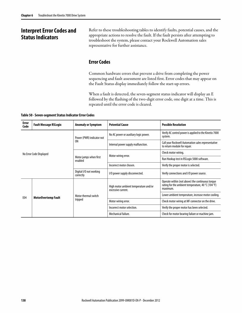
Chapter 6 Troubleshoot the Kinetix 7000 Drive System
Interpret Error Codes and Status Indicators
Refer to these troubleshooting tables to identify faults, potential causes, and the appropriate actions to resolve the fault. If the fault persists after attempting to troubleshoot the system, please contact your Rockwell Automation sales representative for further assistance.
Error Codes
Common hardware errors that prevent a drive from completing the power sequencing and fault assessment are listed first. Error codes that may appear on the Fault Status display immediately follow the start-up errors.
When a fault is detected, the seven-segment status indicator will display an E followed by the flashing of the two-digit error code, one digit at a time. This is repeated until the error code is cleared.
Table 50 - Seven-segment Status Indicator Error Codes
Error Code Fault Message RSLogix Anomaly or Symptom Potential Cause Possible Resolution
No Error Code Displayed
Power (PWR) indicator not ON
No AC power or auxiliary logic power. Verify AC control power is applied to the Kinetix 7000 system.
Internal power supply malfunction. Call your Rockwell Automation sales representative to return module for repair.
Motor jumps when first enabled
Motor wiring error.Check motor wiring.
Run Hookup test in RSLogix 5000 software.
Incorrect motor chosen. Verify the proper motor is selected.
Digital I/O not working correctly I/O power supply disconnected. Verify connections and I/O power source.
E04 MotorOvertemp Fault Motor thermal switch tripped
High motor ambient temperature and/or excessive current.
Operate within (not above) the continuous torque rating for the ambient temperature, 40 °C (104 °F) maximum.
Lower ambient temperature, increase motor cooling.
Motor wiring error. Check motor wiring at MF connector on the drive.
Incorrect motor selection. Verify the proper motor has been selected.
Mechanical failure. Check for motor bearing failure or machine jam.
138 Rockwell Automation Publication 2099-UM001D-EN-P - December 2012
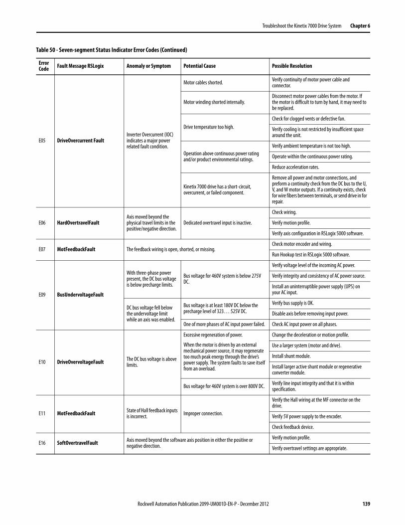
Troubleshoot the Kinetix 7000 Drive System Chapter 6
E05 DriveOvercurrent FaultInverter Overcurrent (IOC) indicates a major power related fault condition.
Motor cables shorted. Verify continuity of motor power cable and connector.
Motor winding shorted internally.Disconnect motor power cables from the motor. If the motor is difficult to turn by hand, it may need to be replaced.
Drive temperature too high.Check for clogged vents or defective fan.
Verify cooling is not restricted by insufficient space around the unit.
Operation above continuous power rating and/or product environmental ratings.
Verify ambient temperature is not too high.
Operate within the continuous power rating.
Reduce acceleration rates.
Kinetix 7000 drive has a short-circuit, overcurrent, or failed component.
Remove all power and motor connections, and preform a continuity check from the DC bus to the U, V, and W motor outputs. If a continuity exists, check for wire fibers between terminals, or send drive in for repair.
E06 HardOvertravelFaultAxis moved beyond the physical travel limits in the positive/negative direction.
Dedicated overtravel input is inactive.
Check wiring.
Verify motion profile.
Verify axis configuration in RSLogix 5000 software.
E07 MotFeedbackFault The feedback wiring is open, shorted, or missing.Check motor encoder and wiring.
Run Hookup test in RSLogix 5000 software.
E09 BusUndervoltageFault
With three-phase power present, the DC bus voltage is below precharge limits.
Bus voltage for 460V system is below 275V DC.
Verify voltage level of the incoming AC power.
Verify integrity and consistency of AC power source.
Install an uninterruptible power supply (UPS) on your AC input.
DC bus voltage fell below the undervoltage limit while an axis was enabled.
Bus voltage is at least 180V DC below the precharge level of 323… 525V DC.
Verify bus supply is OK.
Disable axis before removing input power.
One of more phases of AC input power failed. Check AC input power on all phases.
E10 DriveOvervoltageFault The DC bus voltage is above limits.
Excessive regeneration of power.
When the motor is driven by an external mechanical power source, it may regenerate too much peak energy through the drive’s power supply. The system faults to save itself from an overload.
Change the deceleration or motion profile.
Use a larger system (motor and drive).
Install shunt module.
Install larger active shunt module or regenerative converter module.
Bus voltage for 460V system is over 800V DC. Verify line input integrity and that it is within specification.
E11 MotFeedbackFault State of Hall feedback inputs is incorrect. Improper connection.
Verify the Hall wiring at the MF connector on the drive.
Verify 5V power supply to the encoder.
Check feedback device.
E16 SoftOvertravelFault Axis moved beyond the software axis position in either the positive or negative direction.
Verify motion profile.
Verify overtravel settings are appropriate.
Table 50 - Seven-segment Status Indicator Error Codes (Continued)
Error Code Fault Message RSLogix Anomaly or Symptom Potential Cause Possible Resolution
Rockwell Automation Publication 2099-UM001D-EN-P - December 2012 139

Chapter 6 Troubleshoot the Kinetix 7000 Drive System
E18 OverSpeedFaultMotor speed has exceeded 150% of maximum rated speed. The 100% trip point is dictated by the lesser of the user velocity limits or the motor rated base speed.
Check cables for noise.
Check tuning.
Check feedback device.
Verify velocity limit settings.
E19 PositionErrorFault Position error limit exceeded.
Increase the feed forward gain.
Increase following error limit or time.
Check position loop tuning.
Verify sizing of system.
Verify mechanical integrity of system within specification limits.
E20 MotFeedbackFault Motor encoder state error. The motor encoder encountered an illegal transition.
Use shielded cables with twisted pair wires.
Route the feedback away from potential noise sources.
Check the system grounds.
Replace the motor/encoder.
Check feedback device and wiring.
E21 AuxFeedbackFault Communication was not established with an intelligent encoder. Verify auxiliary encoder wiring.
E23 DriveOvertempFault IPM thermal protection fault
The internal filter protecting the drive from overheating has tripped.
Reduce acceleration rates.
Reduce duty cycle (ON/OFF) of commanded motion.
Increase time permitted for motion.
Use larger Kinetix 7000 drive and motor.
Check tuning.
E30 MotFeedbackFault Communication was not established with an intelligent encoder.
Verify motor selection.
Verify the motor supports automatic identification.
Verify motor encoder wiring.
E34 GroundShortFault Excessive ground current detected in the converter.
Wiring error.Check motor power wiring.
Check input power wiring.
Motor internal ground short. Replace motor.
Internal malfunction.
Disconnect motor power cable from drive and enable drive with current limit set to 0. If fault clears, then a wiring error or motor internal problem exists. If fault remains, call your Rockwell Automation sales representative.
Remove ground from control power input.
Wire control power to use main power as shown in Appendix B.
Add isolation transformer for control power.
E35 DriveUndervoltageFault Converter precharge cycle failed.
Low AC input voltage. Check input AC voltage on all phases.
Internal malfunction. Call your Rockwell Automation sales representative.
E37 PowerPhaseLossFault One or more phases of the ac input power is missing.Check input ac voltage and fusing on all phases and DC bus.
Disable axis before removing power.
Table 50 - Seven-segment Status Indicator Error Codes (Continued)
Error Code Fault Message RSLogix Anomaly or Symptom Potential Cause Possible Resolution
140 Rockwell Automation Publication 2099-UM001D-EN-P - December 2012
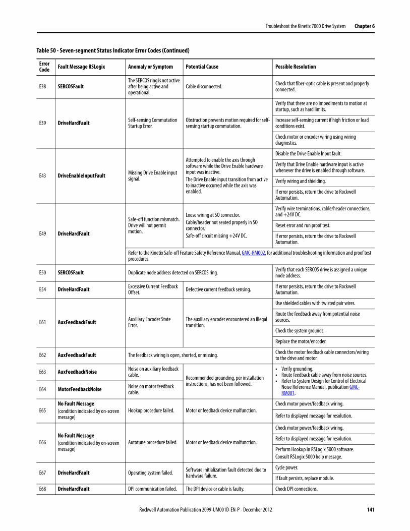
Troubleshoot the Kinetix 7000 Drive System Chapter 6
E38 SERCOSFaultThe SERCOS ring is not active after being active and operational.
Cable disconnected. Check that fiber-optic cable is present and properly connected.
E39 DriveHardFault Self-sensing Commutation Startup Error.
Obstruction prevents motion required for self-sensing startup commutation.
Verify that there are no impediments to motion at startup, such as hard limits.
Increase self-sensing current if high friction or load conditions exist.
Check motor or encoder wiring using wiring diagnostics.
E43 DriveEnableInputFault Missing Drive Enable input signal.
Attempted to enable the axis through software while the Drive Enable hardware input was inactive.The Drive Enable input transition from active to inactive occurred while the axis was enabled.
Disable the Drive Enable Input fault.
Verify that Drive Enable hardware input is active whenever the drive is enabled through software.
Verify wiring and shielding.
If error persists, return the drive to Rockwell Automation.
E49 DriveHardFault
Safe-off function mismatch. Drive will not permit motion.
Loose wiring at SO connector.Cable/header not seated properly in SO connector.Safe-off circuit missing +24V DC.
Verify wire terminations, cable/header connections, and +24V DC.
Reset error and run proof test.
If error persists, return the drive to Rockwell Automation.
Refer to the Kinetix Safe-off Feature Safety Reference Manual, GMC-RM002, for additional troubleshooting information and proof test procedures.
E50 SERCOSFault Duplicate node address detected on SERCOS ring. Verify that each SERCOS drive is assigned a unique node address.
E54 DriveHardFault Excessive Current Feedback Offset. Defective current feedback sensing. If error persists, return the drive to Rockwell
Automation.
E61 AuxFeedbackFault Auxiliary Encoder State Error.
The auxiliary encoder encountered an illegal transition.
Use shielded cables with twisted pair wires.
Route the feedback away from potential noise sources.
Check the system grounds.
Replace the motor/encoder.
E62 AuxFeedbackFault The feedback wiring is open, shorted, or missing. Check the motor feedback cable connectors/wiring to the drive and motor.
E63 AuxFeedbackNoise Noise on auxiliary feedback cable. Recommended grounding, per installation
instructions, has not been followed.
• Verify grounding.• Route feedback cable away from noise sources.• Refer to System Design for Control of Electrical
Noise Reference Manual, publication GMC-RM001.
E64 MotorFeedbackNoise Noise on motor feedback cable.
E65No Fault Message(condition indicated by on-screen message)
Hookup procedure failed. Motor or feedback device malfunction.Check motor power/feedback wiring.
Refer to displayed message for resolution.
E66No Fault Message(condition indicated by on-screen message)
Autotune procedure failed. Motor or feedback device malfunction.
Check motor power/feedback wiring.
Refer to displayed message for resolution.
Perform Hookup in RSLogix 5000 software.Consult RSLogix 5000 help message.
E67 DriveHardFault Operating system failed. Software initialization fault detected due to hardware failure.
Cycle power.
If fault persists, replace module.
E68 DriveHardFault DPI communication failed. The DPI device or cable is faulty. Check DPI connections.
Table 50 - Seven-segment Status Indicator Error Codes (Continued)
Error Code Fault Message RSLogix Anomaly or Symptom Potential Cause Possible Resolution
Rockwell Automation Publication 2099-UM001D-EN-P - December 2012 141
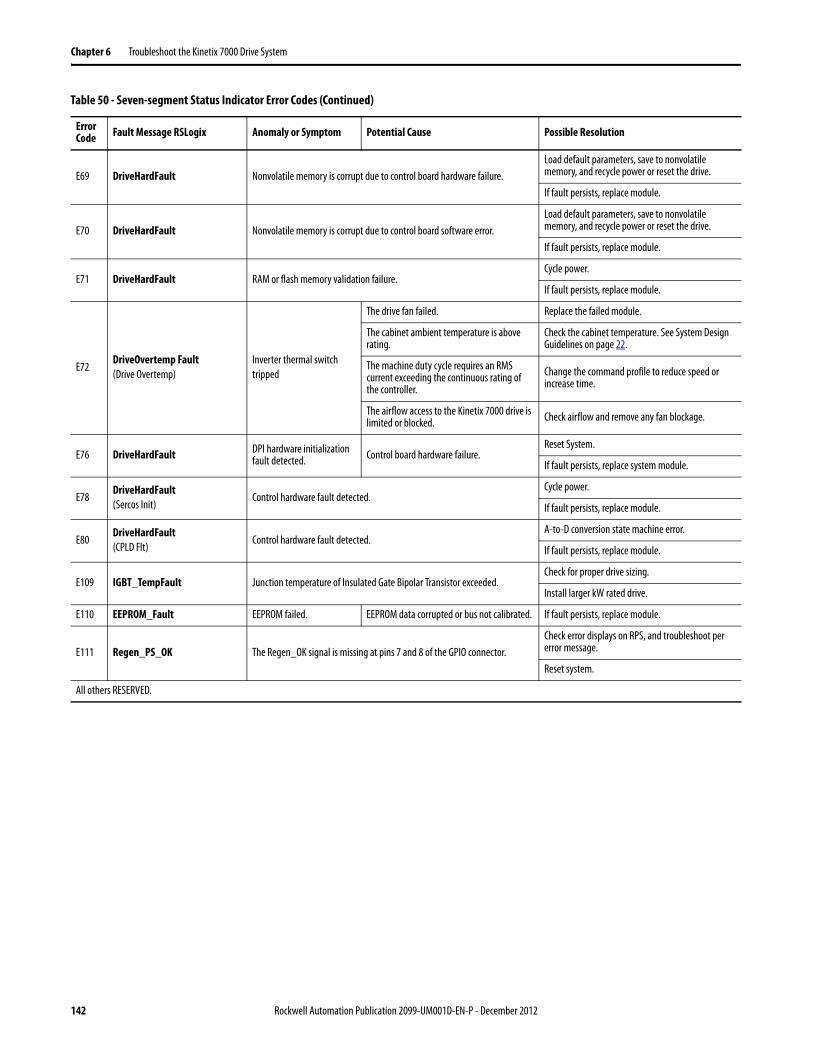
Chapter 6 Troubleshoot the Kinetix 7000 Drive System
E69 DriveHardFault Nonvolatile memory is corrupt due to control board hardware failure.Load default parameters, save to nonvolatile memory, and recycle power or reset the drive.
If fault persists, replace module.
E70 DriveHardFault Nonvolatile memory is corrupt due to control board software error.Load default parameters, save to nonvolatile memory, and recycle power or reset the drive.
If fault persists, replace module.
E71 DriveHardFault RAM or flash memory validation failure.Cycle power.
If fault persists, replace module.
E72DriveOvertemp Fault(Drive Overtemp)
Inverter thermal switchtripped
The drive fan failed. Replace the failed module.
The cabinet ambient temperature is above rating.
Check the cabinet temperature. See System Design Guidelines on page 22.
The machine duty cycle requires an RMS current exceeding the continuous rating of the controller.
Change the command profile to reduce speed or increase time.
The airflow access to the Kinetix 7000 drive is limited or blocked. Check airflow and remove any fan blockage.
E76 DriveHardFault DPI hardware initialization fault detected. Control board hardware failure.
Reset System.
If fault persists, replace system module.
E78DriveHardFault(Sercos Init)
Control hardware fault detected.Cycle power.
If fault persists, replace module.
E80DriveHardFault(CPLD Flt)
Control hardware fault detected.A-to-D conversion state machine error.
If fault persists, replace module.
E109 IGBT_TempFault Junction temperature of Insulated Gate Bipolar Transistor exceeded.Check for proper drive sizing.
Install larger kW rated drive.
E110 EEPROM_Fault EEPROM failed. EEPROM data corrupted or bus not calibrated. If fault persists, replace module.
E111 Regen_PS_OK The Regen_OK signal is missing at pins 7 and 8 of the GPIO connector.Check error displays on RPS, and troubleshoot per error message.
Reset system.
All others RESERVED.
Table 50 - Seven-segment Status Indicator Error Codes (Continued)
Error Code Fault Message RSLogix Anomaly or Symptom Potential Cause Possible Resolution
142 Rockwell Automation Publication 2099-UM001D-EN-P - December 2012

Troubleshoot the Kinetix 7000 Drive System Chapter 6
Status Indicators
Table 51 - Drive Status Indicator
Table 52 - Comm Status Indicator
Table 53 - Bus Status Indicator
Drive Status LED Status Potential Cause Possible Resolution
Off Normal, no faults N/A N/A
Steady Red Drive faulted Seven-segment status indicator displays error code. See the Error Codes on page 138 section and continue troubleshooting.
Comm Status LED Status Potential Cause Possible Resolution
Off No communication (1) Loose fiber-optic connection. Verify proper fiber-optic cable connection.
Broken fiber-optic cable. Replace fiber-optic cable.
Receive fiber-optic cable connected to SERCOS transmit connector and vice versa.
Check proper SERCOS fiber-optic cable connections.
Flashing Green Establishing communication System is still in the process of establishing SERCOS communication.
Wait for steady green indicator.
Node address setting on the drive module does not match SERCOS controller configuration.
Verify proper node switch setting.
Steady Green Communication ready No faults or failures. N/A
(1) Refer to Fiber-optic Cable Installation and Handling Instructions, publication 2090-IN010, for more information.
Bus Status LED Status Condition
Off Bus power not present. • Normal when bus power is not applied.• Fault exists, see the Interpret Error Codes and Status Indicators beginning on page 138.
Bus power is present in follower drive. • Follower drive is not configured as Common Bus Follow in RSLogix 5000 software.• After DC bus voltage is applied, a 2.50 second delay occurs before the indicator begins flashing
green.This is normal operation and provides the common bus leader time to complete precharge.
Alternating Red-Green Bus power not present.24V DC control power is present.
• Normal when bus power is not applied. Verify 460V AC connections.• Fault exists, see the Interpret Error Codes and Status Indicators beginning on page 138.
Flashing Green Bus power is present, axis disabled.No faults or failures.
Normal when:• 24V is not applied to Hardware Enable Input (IOD-2).• MSO instruction is not commanded in RSLogix 5000 software.
Steady Green Bus power is present, axis enabled.No faults or failures.
Normal when:• 24V is applied to Hardware Enable Input (IOD-2).• MSO instruction is commanded in RSLogix 5000 software.
Rockwell Automation Publication 2099-UM001D-EN-P - December 2012 143
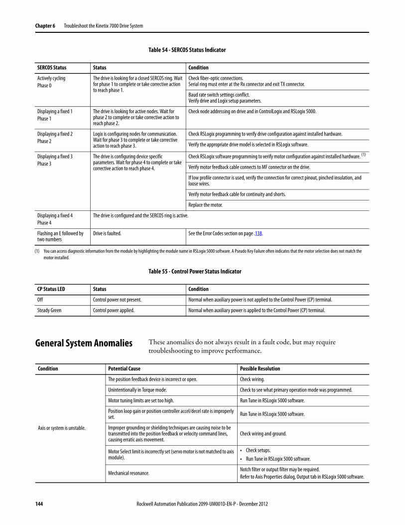
Chapter 6 Troubleshoot the Kinetix 7000 Drive System
Table 54 - SERCOS Status Indicator
Table 55 - Control Power Status Indicator
General System Anomalies These anomalies do not always result in a fault code, but may require troubleshooting to improve performance.
SERCOS Status Status Condition
Actively cyclingPhase 0
The drive is looking for a closed SERCOS ring. Wait for phase 1 to complete or take corrective action to reach phase 1.
Check fiber-optic connections.Serial ring must enter at the Rx connector and exit TX connector.
Baud rate switch settings conflict. Verify drive and Logix setup parameters.
Displaying a fixed 1Phase 1
The drive is looking for active nodes. Wait for phase 2 to complete or take corrective action to reach phase 2.
Check node addressing on drive and in ControlLogix and RSLogix 5000.
Displaying a fixed 2Phase 2
Logix is configuring nodes for communication. Wait for phase 3 to complete or take corrective action to reach phase 3.
Check RSLogix programming to verify drive configuration against installed hardware.
Verify the appropriate drive model is selected in RSLogix software.
Displaying a fixed 3Phase 3
The drive is configuring device specific parameters. Wait for phase 4 to complete or take corrective action to reach phase 4.
Check RSLogix software programming to verify motor configuration against installed hardware. (1)
Verify motor feedback cable connects to MF connector on the drive.
If low profile connector is used, verify the connection for correct pinout, pinched insulation, and loose wires.
Verify motor feedback cable for continuity and shorts.
Replace the motor.
Displaying a fixed 4Phase 4
The drive is configured and the SERCOS ring is active.
Flashing an E followed by two numbers
Drive is faulted. See the Error Codes section on page .138.
(1) You can access diagnostic information from the module by highlighting the module name in RSLogix 5000 software. A Pseudo Key Failure often indicates that the motor selection does not match the motor installed.
CP Status LED Status Condition
Off Control power not present. Normal when auxiliary power is not applied to the Control Power (CP) terminal.
Steady Green Control power applied. Normal when auxiliary power is applied to the Control Power (CP) terminal.
Condition Potential Cause Possible Resolution
Axis or system is unstable.
The position feedback device is incorrect or open. Check wiring.
Unintentionally in Torque mode. Check to see what primary operation mode was programmed.
Motor tuning limits are set too high. Run Tune in RSLogix 5000 software.
Position loop gain or position controller accel/decel rate is improperly set. Run Tune in RSLogix 5000 software.
Improper grounding or shielding techniques are causing noise to be transmitted into the position feedback or velocity command lines, causing erratic axis movement.
Check wiring and ground.
Motor Select limit is incorrectly set (servo motor is not matched to axis module).
• Check setups.• Run Tune in RSLogix 5000 software.
Mechanical resonance.Notch filter or output filter may be required.Refer to Axis Properties dialog, Output tab in RSLogix 5000 software.
144 Rockwell Automation Publication 2099-UM001D-EN-P - December 2012
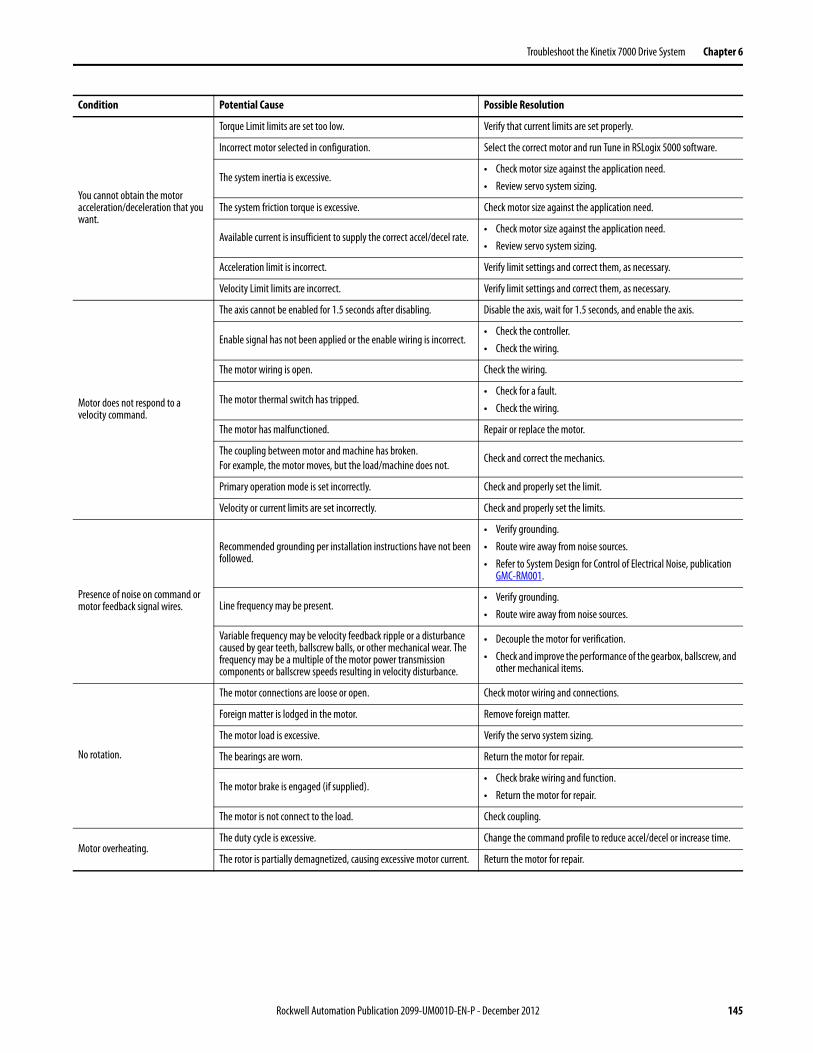
Troubleshoot the Kinetix 7000 Drive System Chapter 6
You cannot obtain the motor acceleration/deceleration that you want.
Torque Limit limits are set too low. Verify that current limits are set properly.
Incorrect motor selected in configuration. Select the correct motor and run Tune in RSLogix 5000 software.
The system inertia is excessive.• Check motor size against the application need.• Review servo system sizing.
The system friction torque is excessive. Check motor size against the application need.
Available current is insufficient to supply the correct accel/decel rate.• Check motor size against the application need.• Review servo system sizing.
Acceleration limit is incorrect. Verify limit settings and correct them, as necessary.
Velocity Limit limits are incorrect. Verify limit settings and correct them, as necessary.
Motor does not respond to a velocity command.
The axis cannot be enabled for 1.5 seconds after disabling. Disable the axis, wait for 1.5 seconds, and enable the axis.
Enable signal has not been applied or the enable wiring is incorrect.• Check the controller.• Check the wiring.
The motor wiring is open. Check the wiring.
The motor thermal switch has tripped.• Check for a fault.• Check the wiring.
The motor has malfunctioned. Repair or replace the motor.
The coupling between motor and machine has broken.For example, the motor moves, but the load/machine does not.
Check and correct the mechanics.
Primary operation mode is set incorrectly. Check and properly set the limit.
Velocity or current limits are set incorrectly. Check and properly set the limits.
Presence of noise on command or motor feedback signal wires.
Recommended grounding per installation instructions have not been followed.
• Verify grounding.• Route wire away from noise sources.• Refer to System Design for Control of Electrical Noise, publication
GMC-RM001.
Line frequency may be present.• Verify grounding.• Route wire away from noise sources.
Variable frequency may be velocity feedback ripple or a disturbance caused by gear teeth, ballscrew balls, or other mechanical wear. The frequency may be a multiple of the motor power transmission components or ballscrew speeds resulting in velocity disturbance.
• Decouple the motor for verification.• Check and improve the performance of the gearbox, ballscrew, and
other mechanical items.
No rotation.
The motor connections are loose or open. Check motor wiring and connections.
Foreign matter is lodged in the motor. Remove foreign matter.
The motor load is excessive. Verify the servo system sizing.
The bearings are worn. Return the motor for repair.
The motor brake is engaged (if supplied).• Check brake wiring and function.• Return the motor for repair.
The motor is not connect to the load. Check coupling.
Motor overheating.The duty cycle is excessive. Change the command profile to reduce accel/decel or increase time.
The rotor is partially demagnetized, causing excessive motor current. Return the motor for repair.
Condition Potential Cause Possible Resolution
Rockwell Automation Publication 2099-UM001D-EN-P - December 2012 145
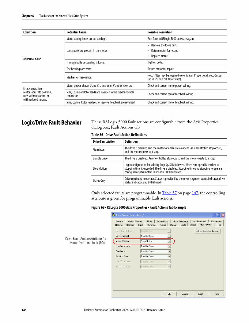
Chapter 6 Troubleshoot the Kinetix 7000 Drive System
Logix/Drive Fault Behavior These RSLogix 5000 fault actions are configurable from the Axis Properties dialog box, Fault Actions tab.
Table 56 - Drive Fault Action Definitions
Only selected faults are programmable. In Table 57 on page 147, the controlling attribute is given for programmable fault actions.
Figure 68 - RSLogix 5000 Axis Properties - Fault Actions Tab Example
Abnormal noise
Motor tuning limits are set too high. Run Tune in RSLogix 5000 software again.
Loose parts are present in the motor.• Remove the loose parts.• Return motor for repair.• Replace motor.
Through bolts or coupling is loose. Tighten bolts.
The bearings are worn. Return motor for repair.
Mechanical resonance. Notch filter may be required (refer to Axis Properties dialog, Output tab in RSLogix 5000 software).
Erratic operation - Motor locks into position, runs without control or with reduced torque.
Motor power phases U and V, U and W, or V and W reversed. Check and correct motor power wiring.
Sine, Cosine or Rotor leads are reversed in the feedback cable connector. Check and correct motor feedback wiring.
Sine, Cosine, Rotor lead sets of resolver feedback are reversed. Check and correct motor feedback wiring.
Condition Potential Cause Possible Resolution
Drive Fault Action Definition
Shutdown The drive is disabled and the contactor enable relay opens. An uncontrolled stop occurs, and the motor coasts to a stop.
Disable Drive The drive is disabled. An uncontrolled stop occurs, and the motor coasts to a stop.
Stop MotionLogix configuration for velocity loop Kp/Ki is followed. When zero speed is reached or stopping time is exceeded, the drive is disabled. Stopping time and stopping torque are configurable parameters in RSLogix 5000 software.
Status Only Drive continues to operate. Status is provided by the seven-segment status indicator, drive status indicator, and DPI (if used).
Drive Fault Action/Attribute forMotor Overtemp fault (E04).
146 Rockwell Automation Publication 2099-UM001D-EN-P - December 2012
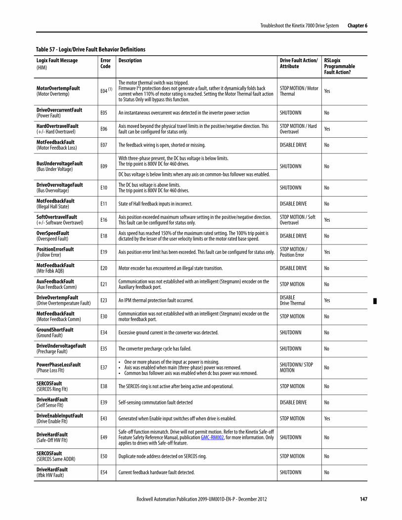
Troubleshoot the Kinetix 7000 Drive System Chapter 6
Table 57 - Logix/Drive Fault Behavior Definitions
Logix Fault Message(HIM)
ErrorCode
Description Drive Fault Action/Attribute
RSLogix Programmable Fault Action?
MotorOvertempFault(Motor Overtemp) E04 (1)
The motor thermal switch was tripped.Firmware I2t protection does not generate a fault, rather it dynamically folds back current when 110% of motor rating is reached. Setting the Motor Thermal fault action to Status Only will bypass this function.
STOP MOTION / Motor Thermal Yes
DriveOvercurrentFault(Power Fault) E05 An instantaneous overcurrent was detected in the inverter power section SHUTDOWN No
HardOvertravelFault(+/- Hard Overtravel) E06 Axis moved beyond the physical travel limits in the positive/negative direction. This
fault can be configured for status only.STOP MOTION / Hard Overtravel Yes
MotFeedbackFault(Motor Feedback Loss) E07 The feedback wiring is open, shorted or missing. DISABLE DRIVE No
BusUndervoltageFault(Bus Under Voltage) E09
With three-phase present, the DC bus voltage is below limits.The trip point is 800V DC for 460 drives. SHUTDOWN NoDC bus voltage is below limits when any axis on common-bus follower was enabled.
DriveOvervoltageFault(Bus Overvoltage) E10 The DC bus voltage is above limits.
The trip point is 800V DC for 460 drives. SHUTDOWN No
MotFeedbackFault(Illegal Hall State) E11 State of Hall feedback inputs in incorrect. DISABLE DRIVE No
SoftOvertravelFault(+/- Software Overtravel) E16 Axis position exceeded maximum software setting in the positive/negative direction.
This fault can be configured for status only.STOP MOTION / Soft Overtravel Yes
OverSpeedFault(Overspeed Fault) E18 Axis speed has reached 150% of the maximum rated setting. The 100% trip point is
dictated by the lesser of the user velocity limits or the motor rated base speed. DISABLE DRIVE No
PositionErrorFault(Follow Error) E19 Axis position error limit has been exceeded. This fault can be configured for status only. STOP MOTION /
Position Error Yes
MotFeedbackFault(Mtr Fdbk AQB) E20 Motor encoder has encountered an illegal state transition. DISABLE DRIVE No
AuxFeedbackFault(Aux Feedback Comm) E21 Communication was not established with an intelligent (Stegmann) encoder on the
Auxiliary feedback port. STOP MOTION No
DriveOvertempFault(Drive Overtemperature Fault) E23 An IPM thermal protection fault occurred. DISABLE
Drive Thermal Yes
MotFeedbackFault(Motor Feedback Comm) E30 Communication was not established with an intelligent (Stegmann) encoder on the
motor feedback port. STOP MOTION No
GroundShortFault(Ground Fault) E34 Excessive ground current in the converter was detected. SHUTDOWN No
DriveUndervoltageFault(Precharge Fault) E35 The converter precharge cycle has failed. SHUTDOWN No
PowerPhaseLossFault(Phase Loss Flt) E37
• One or more phases of the input ac power is missing.• Axis was enabled when main (three-phase) power was removed.• Common bus follower axis was enabled when dc bus power was removed.
SHUTDOWN/ STOP MOTION No
SERCOSFault(SERCOS Ring Flt) E38 The SERCOS ring is not active after being active and operational. STOP MOTION No
DriveHardFault(Self Sense Flt) E39 Self-sensing commutation fault detected DISABLE DRIVE No
DriveEnableInputFault(Drive Enable Flt) E43 Generated when Enable input switches off when drive is enabled. STOP MOTION Yes
DriveHardFault(Safe-Off HW Flt) E49
Safe-off function mismatch. Drive will not permit motion. Refer to the Kinetix Safe-off Feature Safety Reference Manual, publication GMC-RM002, for more information. Only applies to drives with Safe-off feature.
SHUTDOWN No
SERCOSFault(SERCOS Same ADDR) E50 Duplicate node address detected on SERCOS ring. STOP MOTION No
DriveHardFault(Ifbk HW Fault) E54 Current feedback hardware fault detected. SHUTDOWN No
Rockwell Automation Publication 2099-UM001D-EN-P - December 2012 147

Chapter 6 Troubleshoot the Kinetix 7000 Drive System
AuxFeedbackFault(Aux Fdbk AQB) E61 Auxiliary encoder has encountered an illegal state transition. DISABLE DRIVE No
AuxFeedbackFault(Aux Fdbk Loss) E62 The feedback wiring is open, shorted or missing. DISABLE DRIVE No
AuxFeedbackNoise(Aux Fdbk Noise) E63 Presence of noise on auxiliary feedback cable.
DISABLE DRIVE / Feedback Noise Yes
MotorFeedbackNoise(Mtr Fdbk Noise) E64 Presence of noise on motor feedback cable.
No Fault Message (condition indicated by on-screen message)(Hookup Fault)
E65 Hookup procedure failed. DISABLE DRIVE No
No Fault Message (condition indicated by on-screen message)(Atune Flt)
E66 Autotune procedure failed. DISABLE DRIVE No
DriveHardFault(Task Init) E67 Operating system failed. SHUTDOWN No
DriveHardFault(SCANport Comm) E68 DPI communication failed. STOP MOTION No
DriveHardFault(Objects Init) E69 Nonvolatile memory attribute out of range. SHUTDOWN No
DriveHardFault(NV Mem Init) E70 Nonvolatile memory corrupted. SHUTDOWN No
DriveHardFault(Memory Init) E71 RAM or flash memory validation failure. SHUTDOWN No
DriveOvertempFault(Drive Overtemp) E72 Inverter temperature limit exceeded. Firmware I2t protection does not generate a fault,
rather it dynamically folds back current when 110% of drive rating is reached. SHUTDOWN Yes
DriveHardFault(Can Init) E76 Either DPI or backplane CAN initialization failure. SHUTDOWN No
DriveHardFaultSERCOS Init E78 Control hardware fault detected. SHUTDOWN No
HardwareFault(CPLD FLT) E80 Control hardware fault detected. SHUTDOWN No
IGBTTempFault(IGBTFLT) E109 Junction temperature of IGBT exceeded. SHUTDOWN No
EEPROMFault(CPLD FLT) E110 EEPROM failure. EEPROM data corrupt or bus not calibrated. SHUTDOWN No
RegenPSOK(CPLD FLT) E111 Regenerative PS+/- missing at GPIO. SHUTDOWN No
All Others RESERVED
(1) The Logix Motor Thermal Fault Action is tied to the motor thermostat fault. If this is set to Shutdown or Disable (in Logix), the drive will fold back the current when the I2T calculation indicates that the motor temperature has exceeded 10% of its rated temperature. If it is set to Stop Motion or Status Only, the drive will not fold back the current. The I2T calculation never generates a fault.
Logix Fault Message(HIM)
ErrorCode
Description Drive Fault Action/Attribute
RSLogix Programmable Fault Action?
148 Rockwell Automation Publication 2099-UM001D-EN-P - December 2012

Appendix A
Specifications and Dimensions
This appendix provides product specifications and mounting dimensions for your Kinetix 7000 system components.
Topic Page
Power Specifications 150
Power Dissipation Specifications 152
General Specifications 153
AC Line Filter Specifications 155
AC Line Reactors 155
External Shunt Modules 155
Precharge Capacities of the Regenerative Power Supply 157
Product Dimensions 157
Rockwell Automation Publication 2099-UM001D-EN-P - December 2012 149

Appendix A Specifications and Dimensions
Power Specifications This section contains power specifications for the Kinetix 7000 drive.
Attribute 2099-BM06-S 2099-BM07-S 2099-BM08-S 2099-BM09-S 2099-BM10-S 2099-BM11-S 2099-BM12-S
AC input voltage 342…528V AC rms three-phase (380…480V nom)
AC input frequency 47…63 Hz
Bandwidth (1)
Velocity loopCurrent loop
500 Hz1300 Hz
500 Hz500 Hz
PWM frequency 4 kHz 2 kHz
Main AC input currentNom (rms)Max inrush (A peak)
36.7 A18.0 A
47.7 A18.0 A
59.6 A18.0 A
90.1 A96.0 A
117 A118 A
169 A141 A
233 A141 A
DC input voltage 450…750V DC
DC input current 42.9 A 55.7 A 69.7 A 105 A 137 A 204 A 281 A
Control power input Voltage 18…30V DC (24V DC, nom)
Control power DC input currentNom (rms)Maximum inrush (rms)
3.3 A6.0 A
Continuous output current (rms) 40.0 A 52.0 A 65.0 A 96.0 A 125 A 180 A 248 A
Continuous output current (0-pk) 56.0 A 73.0 A 92.0 A 135 A 176 A 254 A 351 A
Peak output current (rms)3 s duration60 s duration
68.0 A51.0 A
80.0 A60.0 A
104 A78.0A
154 A115 A
163 A138 A
312 A234 A
372 A273 A
Peak output current (0-pk)3 s duration60 s duration
96.0 A72.0 A
113 A84.8 A
147 A110 A
217.7 A162.6 A
230.5 A195 A
441 A331 A
526 A386 A
Bus overvoltage 800V DC
Bus undervoltage 275…560V DC (2)
Continuous power output, nom 22 kW 30 kW 37 kW 56 kW 75 kW 112 kW 149 kW
Continuous power output (Hp) 30 Hp 40 Hp 50 Hp 75 Hp 100 Hp 150 Hp 200 Hp
Maximum power cycles/minuteAC lineDC bus
4 per minute (pre-charge provided by drive)2 per minute (DC pre-charge provided by the regenerative power supply)
DC bus discharge time 3 minutes after removal of main AC power
Efficiency 97.5%
Total capacitance (3) 1800 μF 2400 μF 3000 μF 4500 μF 6000 μF 8400 μF 8400 μF
Short circuit current rating 200,000 A (rms) symmetrical
(1) Bandwidth values vary based on tuning parameters and mechanical components.(2) Bus undervoltage will vary based on input line voltage.(3) If DC input is supplied to 2099-BM09-S, 2099-BM10-S, 2099-BM11-S, or 2099-BM12-S drives, the precharge capability must be provided at the system level. Disconnect switches must not be used
between the input of the drive and a common DC bus without the use of an external precharge device.
150 Rockwell Automation Publication 2099-UM001D-EN-P - December 2012

Specifications and Dimensions Appendix A
Circuit Breaker/Fuse Specifications
While circuit breakers offer some convenience, there are limitations for their use. Circuit breakers do not handle high current inrush as well as fuses.
Make sure the selected components are properly coordinated and meet acceptable codes including any requirements for branch circuit protection. Evaluation of the short-circuit available current is critical and must be kept below the short-circuit current rating of the circuit breaker.
Use class CC, T, RK1, or J fuses, with current rating as indicated in the table below. The following fuse examples and short-circuit current ratings are recommended for use with the 2099-BMxx-S drives when the Line Interface Module (LIM) is not used.
Table 58 - 460V AC Input Drive Fuse and Motor Circuit Protector Specifications
Common DC Bus Fuse Specifications
Table 59 - Ferraz Shawmut Fuse Recommendations
IMPORTANT LIM modules (catalog numbers 2094-BLxxS and 2094-XL75S-Cx) provide branch circuit protection to the Kinetix 7000 drive. Follow all applicable NEC and local codes.
Drive Cat. No. Bussmann Fuse
Dual Element Time Delay Fuse (min/max)A rms
Non-Time Delay Fuse (min/max)A rms
Motor Circuit Protector (max)A rms
2099-BM06-S LPJ-90SP 50/90 50/150 50
2099-BM07-S LPJ-110SP 60/110 60/200 70
2099-BM08-S LPJ-125SP 80/125 80/250 100
2099-BM09-S LPJ-200SP 125/200 125/300 125
2099-BM10-S LPJ-250SP 150/250 150/500 150
2099-BM11-S LPJ-400SP 225/400 225/600 250
2099-BM12-S LPJ-500SP 300/550 300/700 400
Drive Cat. No.Drive Current Rating (Adc)
Recommended Fuse
Fuse Current Rating
i²t (A²Sec)
Peak Let-Through Current at 100kA rmsPre-Arc
Max. Clearing @ 600V AC
2099-BM06-S 42.9 HSJ80 80 1600 15000 7000 A
2099-BM07-S 55.7 HSJ90 90 2300 21000 7400 A
2099-BM08-S 69.7 HSJ100 100 2700 23000 7700 A
2099-BM09-S 105 HSJ175 175 8000 60000 12000 A
2099-BM10-S 137 HSJ200 200 14000 92000 13000 A
2099-BM11-S 204 HSJ400 400 63000 450000 21000 A
2099-BM12-S 281 HSJ400 400 63000 450000 21000 A
Rockwell Automation Publication 2099-UM001D-EN-P - December 2012 151

Appendix A Specifications and Dimensions
Table 60 - Bussmann Fuse Recommendations
Contactor Ratings
The table below lists the recommended contactor ratings for Kinetix 7000 drives installed without a Line Interface Module (LIM).
Power Dissipation Specifications
Use this table to size an enclosure and calculate required ventilation for your Kinetix 7000 drive system.
Drive Cat. No.Drive Current Rating (Adc)
Recommended Fuse
Fuse Current Rating
i²t (A²Sec)
Peak Let-Through Current at 100kA rmsPre-Arc
Max Clearing @ 600V AC
2099-BM06-S 42.9 FWJ-80A 80 1550 9700 6300 A
2099-BM07-S 55.7 FWJ-100A 100 2800 17500 8000 A
2099-BM08-S 69.7 FWJ-125A 125 4800 35000 10000 A
2099-BM09-S 105 FWJ-175A 175 7500 65000 12000 A
2099-BM10-S 137 FWJ-200A 200 11700 80000 13000 A
2099-BM11-S 204 FWJ-500A 500 39500 329000 21000 A
2099-BM12-S 281 FWJ-500A 500 39500 329000 21000 A
Drive Cat. No. Contactor Safety Contactor Coil Type Coil Voltage Requirements
2099-BM06-S 100-C43DJ01 100S-C43-DJD4C Standard with Diode 24V DC
2099-BM07-S
100-D95EN11 100S-D95EN22C
Electronic Coil (1) 24V DC for control and 480V AC for coil power
2099-BM08-S
2099-BM09-S
2099-BM10-S 100-D140EN11 100S-D140EN22C
2099-BM11-S 100-D180EN11 100S-D180EN22C
2099-BM12-S 100-D250EN11 100S-D250EN22C
(1) Electronic coil control power requirements = 24V DC @ 15 mA.
Drive Cat. No.Usage as a % of Rated Power Output
W
50% 100%
2099-BM06-S 294 465
2099-BM07-S 388 619
2099-BM08-S 452 730
2099-BM09-S 645 1072
2099-BM10-S 882 1479
2099-BM11-S 1275 2125
2099-BM12-S 1438 2437
152 Rockwell Automation Publication 2099-UM001D-EN-P - December 2012

Specifications and Dimensions Appendix A
General Specifications Maximum Feedback Cable Lengths
Although motor power and feedback cables are available in standard lengths up to 90 m (295.3 ft), the drive/motor/feedback combination may limit the maximum feedback cable length. These tables assume the use of recommended 2090-series cables.
Table 61 - Cable Lengths for Compatible Rotary Motors
Weight Specifications
Motor Cat. No.Absolute High-resolution (5V) Encoderm (ft)
Absolute High-resolution (9V) Encoderm (ft)
MPL-B5xxx…MPL-B9xxx-S/M 90 (295.3)
MPM-B165xx…MPM-B215xx-S/M 90 (295.3)
RDB-B215xx-7/3 30 (98.4)
RDB-B290xx-7/3 orRDB-B410xx-7/3 90 (295.3)
HPK-Bxxxxx-S/M orHPK-Exxxxx-S/M 90 (295.3)
Drive Cat. No.Weight, approx.kg (lb)
2099-BM06-S
18.55 (40.9)2099-BM07-S
2099-BM08-S
2099-BM09-S37.2 (82.0)
2099-BM10-S
2099-BM11-S71.4 (157.5)
2099-BM12-S
Rockwell Automation Publication 2099-UM001D-EN-P - December 2012 153
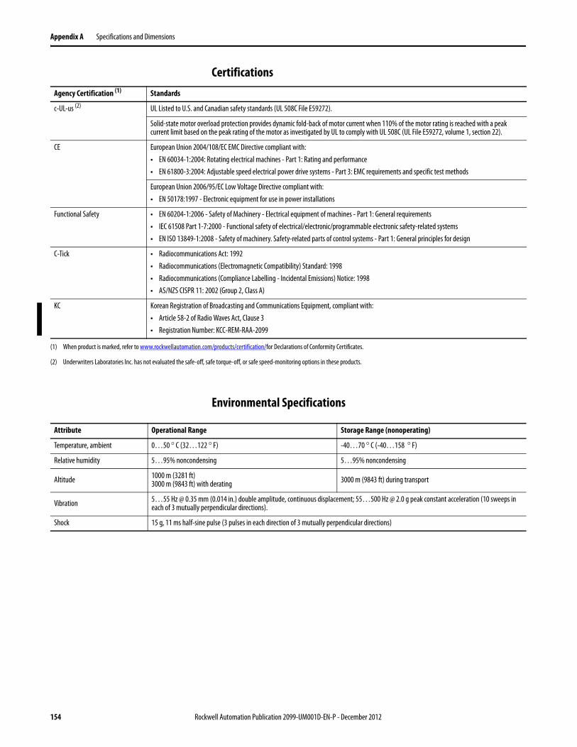
Appendix A Specifications and Dimensions
Certifications
Environmental Specifications
Agency Certification (1) Standards
c-UL-us (2) UL Listed to U.S. and Canadian safety standards (UL 508C File E59272).
Solid-state motor overload protection provides dynamic fold-back of motor current when 110% of the motor rating is reached with a peak current limit based on the peak rating of the motor as investigated by UL to comply with UL 508C (UL File E59272, volume 1, section 22).
CE European Union 2004/108/EC EMC Directive compliant with:• EN 60034-1:2004: Rotating electrical machines - Part 1: Rating and performance• EN 61800-3:2004: Adjustable speed electrical power drive systems - Part 3: EMC requirements and specific test methods
European Union 2006/95/EC Low Voltage Directive compliant with:• EN 50178:1997 - Electronic equipment for use in power installations
Functional Safety • EN 60204-1:2006 - Safety of Machinery - Electrical equipment of machines - Part 1: General requirements• IEC 61508 Part 1-7:2000 - Functional safety of electrical/electronic/programmable electronic safety-related systems• EN ISO 13849-1:2008 - Safety of machinery. Safety-related parts of control systems - Part 1: General principles for design
C-Tick • Radiocommunications Act: 1992• Radiocommunications (Electromagnetic Compatibility) Standard: 1998• Radiocommunications (Compliance Labelling - Incidental Emissions) Notice: 1998• AS/NZS CISPR 11: 2002 (Group 2, Class A)
KC Korean Registration of Broadcasting and Communications Equipment, compliant with:• Article 58-2 of Radio Waves Act, Clause 3• Registration Number: KCC-REM-RAA-2099
(1) When product is marked, refer to www.rockwellautomation.com/products/certification/for Declarations of Conformity Certificates.
(2) Underwriters Laboratories Inc. has not evaluated the safe-off, safe torque-off, or safe speed-monitoring options in these products.
Attribute Operational Range Storage Range (nonoperating)
Temperature, ambient 0…50 ° C (32…122 ° F) -40…70 ° C (-40…158 ° F)
Relative humidity 5…95% noncondensing 5…95% noncondensing
Altitude 1000 m (3281 ft)3000 m (9843 ft) with derating 3000 m (9843 ft) during transport
Vibration 5…55 Hz @ 0.35 mm (0.014 in.) double amplitude, continuous displacement; 55…500 Hz @ 2.0 g peak constant acceleration (10 sweeps in each of 3 mutually perpendicular directions).
Shock 15 g, 11 ms half-sine pulse (3 pulses in each direction of 3 mutually perpendicular directions)
154 Rockwell Automation Publication 2099-UM001D-EN-P - December 2012

Specifications and Dimensions Appendix A
AC Line Filter Specifications Line filters compatible with a Kinetix 7000 drive sourcing input power from an AC power supply are listed below.
Line filters compatible with a Kinetix 7000 drive sourcing input power from a regenerative DC bus with a 8720MC-RPS unit are listed below.
AC Line Reactors 380…480V, 50/60 Hz, three-phase, line reactors compatible with a Kinetix 7000 drive connected to a three-phase, AC input power source are listed below.
Table 62 - Compatible Kinetix 7000 Drives and AC Line Reactors
Kinetix 7000 DriveCat. No.
AC Line FilterCat. No.
2099-BM06-S2090- XXLF-TC350
2099-BM07-S
2099-BM08-S 2090- XXLF-TC365
2099-BM09-S 2090- XXLF-TC3100
2099-BM10-S 2090- XXLF-TC3150
2099-BM11-S 2090- XXLF-TC3200
2099-BM12-S 2090- XXLF-TC3250
8720MC-RPSCat. No.
AC Line Filter Manufacturer and Cat. No.
8720MC-RPS065BM-HV2 Schaffner: FN3100-80-35Soshin Electric: HF3080C-TOA
8720MC-RPS190BM 8720MC-EF190-VB
Kinetix 7000 DriveCat. No.
3% Impedance Input Line Reactor (1) 5% Impedance Input Line Reactor (1)
IP00 (Open Style)Cat. No.
IP11 (NEMA/UL Type 1)Cat. No.
IP00 (Open Style)Cat. No.
IP11 (NEMA/UL Type 1)Cat. No.
2099-BM06-S 1321-3R45-B 1321-3RA45-B 1321-3R45-C 1321-3RA45-C
2099-BM07-S 1321-3R55-B 1321-3RA55-B 1321-3R55-C 1321-3RA55-C
2099-BM08-S 1321-3R80-B 1321-3RA80-B 1321-3R80-C 1321-3RA80-C
2099-BM09-S 1321-3R100-B 1321-3RA100-B 1321-3R100-C 1321-3RA100-C
2099-BM10-S 1321-3R130-B 1321-3RA130-B 1321-3R130-C 1321-3RA130-C
2099-BM11-S 1321-3R200-B 1321-3RA200-B 1321-3R200-C 1321-3RA200-C
2099-BM12-S 1321-3RB250-B 1321-3RAB250-B 1321-3RB250-C 1321-3RAB250-C
(1) Input line reactors were sized based on the NEC fundamental motor amps.
Rockwell Automation Publication 2099-UM001D-EN-P - December 2012 155

Appendix A Specifications and Dimensions
Line reactors compatible with a 8720MC-RPS Regenerative Power Supply sourcing input power from an AC power supply are listed below. They must be configured as shown in the Regenerative Power Supply example on page 169.
Table 63 - Compatible Kinetix 7000 Drives, 8720MC-RPS Regenerative Power Supplies and 8720MC Line Reactors
External Shunt Modules Refer to this table for active shunt solutions for use with Kinetix 7000 drives from Rockwell Automation Encompass Partners.
Kinetix 7000 DriveCat. No.
8720MC-RPS Regenerative Power Supply Cat. No. (1)
(1) Regenerative Power Supply (RPS) selection is for a single motor/drive combination. When combining multiple drives on the same RPS module, the selection will change.
8720MC Line ReactorCat. No.
2099-BM07-S 8720MC-RPS065BM 8720MC-LR05-048B
2099-BM08-S
2099-BM09-S 8720MC-LR10-062B
8720MC-RPS065BM and8720MC-RPS065BS
8720MC-LR05-048B(requires two units, one for the master RPS unit and one for the slave RPS unit.)
2099-BM11-S 8720MC-LR10-062B(requires two units, one for the master RPS unit and one for the slave RPS unit.)
8720MC-RPS190BM 8720MC-LR10-100B (required two units)
2099-BM12-S
Rockwell Automation Encompass Partner Contact Information
Powerohm Resistors, Inc. 5713 13th StreetKaty, TX 77493Tel: (800) 838-4694http://www.powerohm.com
Bonitron, Inc. 521 Fairground Court,Nashville, TN 37211Tel: (615) 244-2825http://www.bonitron.com
156 Rockwell Automation Publication 2099-UM001D-EN-P - December 2012

Specifications and Dimensions Appendix A
Precharge Capacities of the Regenerative Power Supply
Internal (built-in) and external precharge capacities of the regenerative power supply (RPS) are listed below.
Product Dimensions This section provides a quick reference table to common dimensions for Kinetix 7000 drives (height, width, depth, and mounting hole locations), and outline drawings with dimensions related to the specific frame sizes.
Attribute 8720MC-RPS065Bx-HV2 8720MC-RPS190Bx
Rated Output kVa (750V DC bus) (1) 45 133
DC Amperes Continuous (1) 64 190
DC Amperes Peak (1 minute) (1) 96 285
Built-in Capacitor 1900 μF 7600 μF
Built-in Resistor (Resistance/W) 7000 μF (22 Ohms/120 W) 25000 μF (10 Ohms/400 W)
External Resistor (Min Resistance) (2) (3) 110000 μF (20 Ohms) 165000 μF (10 Ohms)
External Circuit (Min Resistance) (3) 220000 μF (4.7 Ohms) 495000 μF (1.5 Ohms)
(1) For 8720MC-RPS065-HV2 and 8720MC-RPS190, you may have up to two slave units with a master unit. Multiply these values by the number of slave units.(2) Use this case only when the bus capacitance exceeds the internal precharge rating. You must use the specified resistor. Calculate rated wattage and surge
resistivity for that resistor. See the 8720MC Regenerative Power Supply Installation Manual, publication 8720MC-RM001, for configuration details.(3) Use this case only when the bus capacitance exceeds the external resistor rating. You must use the specified resistor. Calculate rated wattage and surge
resistivity for that resistor. See the 8720MC Regenerative Power Supply Installation Manual, publication 8720MC-RM001, for configuration details.
IMPORTANT Large levels of load capacitance may require modification of the 8720 regenerative power supply internal precharge/discharge circuit. See the Wiring instructions in the 8720MC Regenerative Power Supply Installation Manual, publication 8720MC-RM001, for information on how to determine the appropriate precharge/discharge resistance power value (Ohms/Watt) to accommodate the capacitance of your system.
Rockwell Automation Publication 2099-UM001D-EN-P - December 2012 157
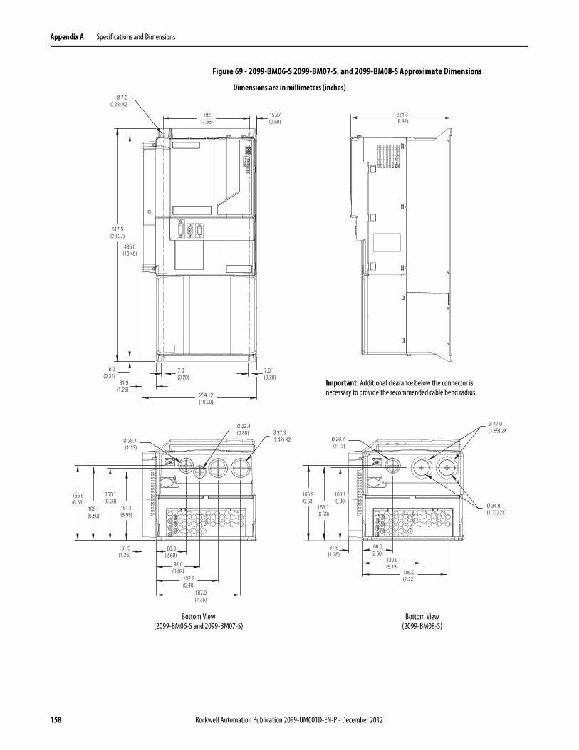
Appendix A Specifications and Dimensions
Figure 69 - 2099-BM06-S 2099-BM07-S, and 2099-BM08-S Approximate Dimensions
224.3(8.82)
7.0(0.28)
31.9(1.26)
517.5(20.37)
495.0(19.49)
254.12(10.00)
192(7.56)
15.27(0.60)
7.0(0.28)
8.0(0.31)
Ø 7.0(0.28) X2
66.0(2.60)
97.0(3.82)
137.2(5.40)
187.0(7.36)
31.9(1.26)
151.1(5.95)
165.1(6.50)
160.1(6.30)
165.9(6.53)
Ø 37.3(1.47) X2
Ø 22.4(0.88)
Ø 28.7(1.13)
66.0(2.60)
130.0(5.19)
186.0(7.32)
31.9(1.26)
Ø 28.7(1.13)
Ø 47.0(1.85) 2X
Ø 34.9(1.37) 2X
165.9(6.53)
165.1(6.50)
160.1(6.30)
Dimensions are in millimeters (inches)
Important: Additional clearance below the connector is necessary to provide the recommended cable bend radius.
Bottom View(2099-BM06-S and 2099-BM07-S)
Bottom View(2099-BM08-S)
158 Rockwell Automation Publication 2099-UM001D-EN-P - December 2012
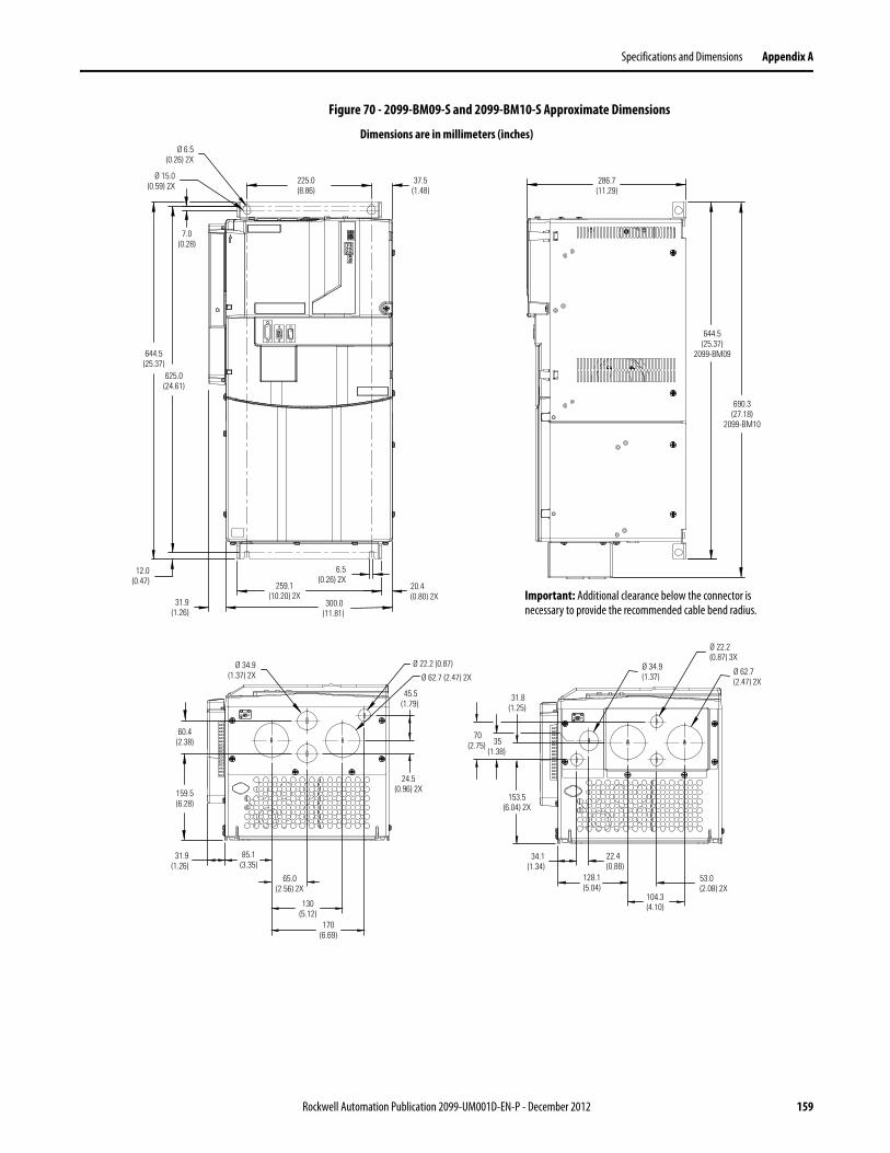
Specifications and Dimensions Appendix A
Figure 70 - 2099-BM09-S and 2099-BM10-S Approximate Dimensions
286.7(11.29)
644.5(25.37)
2099-BM09
6.5(0.26) 2X
31.9(1.26)
20.4(0.80) 2X
300.0(11.81)
259.1(10.20) 2X
Ø 15.0(0.59) 2X
225.0(8.86)
37.5(1.48)
Ø 6.5(0.26) 2X
12.0(0.47)
644.5(25.37)
7.0(0.28)
625.0(24.61)
690.3(27.18)
2099-BM10
Ø 34.9(1.37) 2X
60.4(2.38)
159.5(6.28)
31.9(1.26)
85.1(3.35)
65.0(2.56) 2X
130(5.12)
170(6.69)
24.5(0.96) 2X
45.5(1.79)
Ø 22.2 (0.87)
Ø 62.7 (2.47) 2X
70(2.75) 35
(1.38)
31.8(1.25)
153.5(6.04) 2X
Ø 34.9(1.37)
Ø 22.2(0.87) 3X
Ø 62.7(2.47) 2X
34.1(1.34)
22.4(0.88)
128.1(5.04)
53.0(2.08) 2X
104.3(4.10)
Dimensions are in millimeters (inches)
Important: Additional clearance below the connector is necessary to provide the recommended cable bend radius.
Rockwell Automation Publication 2099-UM001D-EN-P - December 2012 159
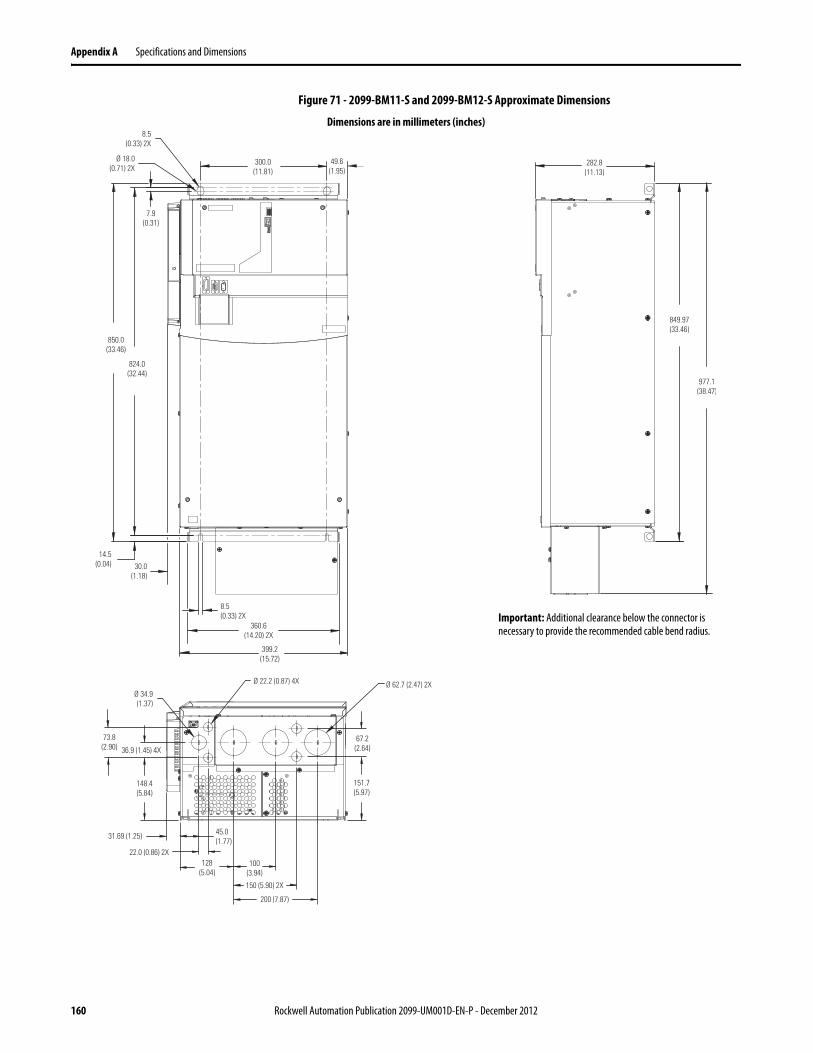
Appendix A Specifications and Dimensions
Figure 71 - 2099-BM11-S and 2099-BM12-S Approximate Dimensions
Ø 18.0(0.71) 2X
8.5(0.33) 2X
300.0(11.81)
49.6(1.95)
7.9(0.31)
850.0(33.46)
824.0(32.44)
14.5(0.04) 30.0
(1.18)
360.6(14.20) 2X
8.5(0.33) 2X
399.2(15.72)
849.97(33.46)
282.8(11.13)
977.1(38.47)
Ø 34.9(1.37)
Ø 22.2 (0.87) 4X Ø 62.7 (2.47) 2X
73.8(2.90) 36.9 (1.45) 4X
148.4(5.84)
31.69 (1.25) 45.0(1.77)
22.0 (0.86) 2X128
(5.04)100
(3.94)
150 (5.90) 2X
200 (7.87)
151.7(5.97)
67.2(2.64)
Dimensions are in millimeters (inches)
Important: Additional clearance below the connector is necessary to provide the recommended cable bend radius.
160 Rockwell Automation Publication 2099-UM001D-EN-P - December 2012

Appendix B
Interconnect Diagrams
This appendix provides wiring examples and system block diagrams to assist you in wiring your Kinetix 7000 system components.
Topic Page
Interconnect Diagram Notes 162
Figure 72 Kinetix 7000 Drive AC Power Wiring 163
Figure 73 Kinetix 7000 Drive AC Powered with a 8720MC-RPS065BM Regenerative Power Supply 164
Figure 74 8720MC-RPS065BM Regenerative Power Supply to a Single Kinetix 7000 Drive 165
Figure 75 8720MC-RPS065BM Regenerative Power Supply to Multiple Kinetix 7000 Drives 166
Figure 76 Dual 8720MC-RPS065Bx Regenerative Power Supplies to a Single Kinetix 7000 Drive 167
Figure 77 Kinetix 7000 Drive AC Powered with a 8720MC-RPS190BM Regenerative Power Supply 168
Figure 78 8720MC-RPS190BM Regenerative Power Supply to a Single Kinetix 7000 Drive 169
Figure 79 8720MC-RPS190BM Regenerative Power Supply to Multiple Kinetix 7000 Drives 170
Figure 80 Dual 8720MC-RPS190Bx Regenerative Power Supplies to a Single Kinetix 7000 Drive 171
Figure 81 Motors with High Resolution Feedback (Bayonet Style Connector) 172
Figure 83 Motors with High Resolution Feedback (Circular DIN Style Connector) 174
Figure 84 HPK-Series High-power Motor with High Resolution Feedback 175
Figure 86 Example with RDD-Series (Bulletin RDB-B) Motors 177
Figure 87 Kinetix Safe-off Feature Block Diagram 178
Rockwell Automation Publication 2099-UM001D-EN-P - December 2012 161

Appendix B Interconnect Diagrams
Interconnect Diagram Notes The notes below apply to the Kinetix 7000 drive wiring examples on the following pages.
Note Information
1 For power wiring specifications, refer to Power Wiring Requirements on page 85.
2 For input fuse and circuit breaker sizes, refer to Circuit Breaker/Fuse Specifications on page 151 and 148.
3 Place AC (EMC) line filters as close to the drive as possible and do not route very dirty wires in wireway. If routing in wireway is unavoidable, use shielded cable with shields grounded to the drive chassis and filter case. For line filter specifications, refer to the AC Line Filter Specifications on page 155. See Establish Noise Zones on page 30 for wire routing guidelines.
4 Contactor coil (M1) needs integrated surge suppressors for AC coil operation. Refer to the Contactor Ratings on page 152 for more information.
5 The default configuration for the ground jumper is for grounded power at the customer site. Ungrounded, impedance grounded, high resistive grounded, B phase grounded, or common DC bus power distribution system sites must disconnect the protective MOVs and Common Mode Capacitors to guard against unstable operation and/or drive damage. Refer to Determine the Input Power Configuration on page 75 for more information.
6
7 Use of an external 24V DC control power supply is recommended for energizing the main control board. This allows the SERCOS ring to remain active when main power is removed. The main control board is powered from the DC bus during drive operation and can be used in this manner, if necessary.
8 The General Purpose Relay outputs on the Kinetix 7000 drive are configured as follows: GPR1+ and GRP1- have noise suppression circuitry and should be used for the motor brake, if used. The default setting for GPR2+ and GPR2- is DROK or Drive_OK. The GPR2 contacts close when external 24V DC control power is applied to the Control Power terminals and there are no shutdown faults.
9 External AC input power for the cooling fan is required only for 2099-BM09-S, 2099-BM10-S, 2099-BM11-S, and 2099-BM12-S drives. The cooling fans on 2099-BM06-S, 2099-BM07-S, and 2099-BM08-S drives are powered internally.
10 Dual 8720MC-RPSxxx units use a ribbon cable to connect the master unit to the slave unit control. The ribbon cable is included with the slave unit.
11 Contact for use with a safety circuit or other system requirement.
ATTENTION: Implementation of safety circuits and risk assessment is the responsibility of the machine builder. Please reference international standards EN 1050 and EN 954 estimation and safety performance categories. For more information, refer to Understanding the Machinery Directive, publication SHB-900.
162 Rockwell Automation Publication 2099-UM001D-EN-P - December 2012
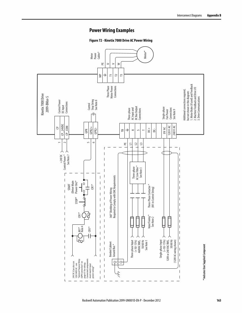
Interconnect Diagrams Appendix B
Power Wiring Examples
Figure 72 - Kinetix 7000 Drive AC Power Wiring
5 6
24V
DC (C
an a
lso u
se12
0/24
0V A
C - s
ee“G
ener
al P
urpo
se R
elay
(GPR
Con
nect
or)”
on
page
61
for r
atin
gs.
Conn
ecte
d co
mpo
nent
sm
ust m
atch
inpu
tpo
wer
ratin
g)*
M1*
CR1*
STOP
*
STAR
T(D
rive
Mai
nPo
wer
On)
*
GPR2
+GP
R2-
GPR
CP_2
4VDC
CP_C
OMCP1 2
PE U V W
T1 T2 T3MP
R S T DC+
DC-
0V A
C
120
V AC
240
V AC
TBPE L1 L2 L3
CR1*
CR1* In
put F
usin
g *Se
e Not
e 2
Mot
orPo
wer
Cable
s*
* Ind
icate
s Use
r Sup
plied
Com
pone
nt
360°
Shiel
ding o
f Pow
er W
iring
Requ
ired t
o Com
ply w
ith EM
C Req
uirem
ents
Bond
ed Ca
binet
Grou
nd Bu
s *
Thre
e Pha
seM
otor
Powe
rCo
nnec
tions
* Ind
icate
s Use
r Sup
plied
Com
pone
nt
Thre
e-ph
ase
AC In
put a
ndDC
Bus O
utpu
tCo
nnec
tions
Singl
e-ph
ase
Fan P
ower
Conn
ectio
nsSe
e Not
e 9
Addit
ional
conn
ectio
ns re
quire
d,bu
t not
show
n in t
his di
agra
m:
1. M
otor
Brak
e (if u
sed)
and F
eedb
ack
2. M
achin
e Fee
dbac
k and
Driv
e I/O
3. Dr
ive Co
mm
unica
tions
Cont
rol
Stop
Strin
gSe
e Not
e 8
Cont
rol P
ower
DC In
put
Conn
ectio
ns
+24
V DC
Cont
rol P
ower
*Se
e Not
e 7
Thre
e-ph
ase I
nput
(+10
/-15%
)46
0VAC
RMS,
50/6
0 Hz
See N
ote 1
Single
-pha
se In
put
(+10
/-15%
)12
0V or
240 V
AC RM
S,50
/60 H
z(1
20V A
C wiri
ng sh
own)
Thre
e-Ph
ase C
onta
ctor *
(M1 i
n Con
trol S
tring
)
Thre
e-ph
ase
AC Li
ne Fi
lter *
See N
ote 3
Kinet
ix 70
00 Dr
ive20
99-B
Mxx
-S
Mot
or*
Not
e 4
Rockwell Automation Publication 2099-UM001D-EN-P - December 2012 163
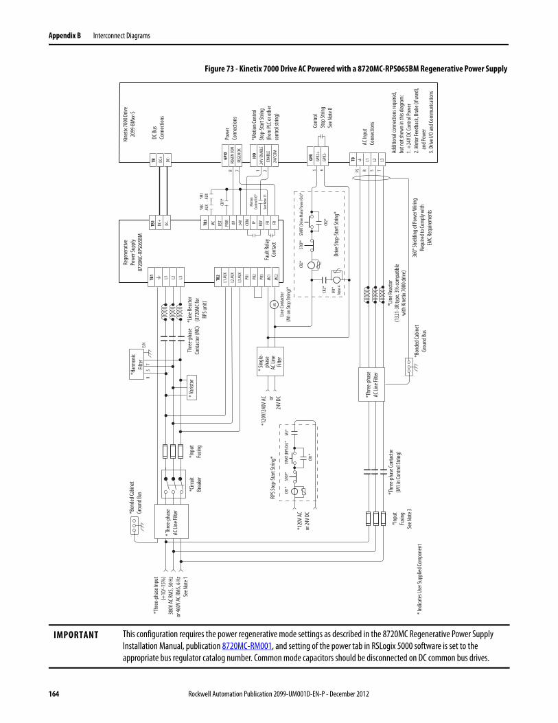
Appendix B Interconnect Diagrams
Figure 73 - Kinetix 7000 Drive AC Powered with a 8720MC-RPS065BM Regenerative Power Supply
IMPORTANT This configuration requires the power regenerative mode settings as described in the 8720MC Regenerative Power Supply Installation Manual, publication 8720MC-RM001, and setting of the power tab in RSLogix 5000 software is set to the appropriate bus regulator catalog number. Common mode capacitors should be disconnected on DC common bus drives.
STOP
*ST
ART (
RPS O
n)*
CR1*
CR1*
E/N
RS
T
MC
STOP
*ST
ART (
Drive
Main
Powe
r On)
*
CR2*
CR2*
CR2*
M1*
Note
4
L1 L2 L3TB1
L1 AU
X
L2 AU
X
L3 AU
X
PR1
PR2
PR3
MC1
MC2
TB2
TB1
DC+
DC-
MC
RST
PWR
0V 24V
COM IP RDY FR FRTB3
5 6 PE R S T8 7
TBREGE
N CO
MRE
GEN
OK
GPIO
DC+
DC-
TB GPR2
+GP
R
*120
V AC
or 24
V DC
L1 L2 L3
M1*
GPR2
-
Drive
Stop
-Sta
rt St
ring*
*Bon
ded C
abin
etGr
ound
Bus
*120
V/24
0V AC or
24V D
C
*Line
Reac
tor
(872
0MC f
orRP
S unit
)
RPS S
top-
Star
t Stri
ng*
*Bon
ded C
abin
etGr
ound
Bus
* Ind
icate
s Use
r Sup
plied
Com
pone
nt
*Thr
ee-p
hase
Inpu
t(+
10/-1
5%)
380V
AC RM
S, 50
Hz
or 46
0V AC
RMS,
6 Hz
See N
ote 1
*Lin
e Rea
ctor
(132
1-3R
type
, 3%
com
patib
lewi
th Ki
netix
7000
drive
)
*Thr
ee-p
hase
Cont
acto
r(M
1 in C
ontro
l Stri
ng)
*Circ
uitBr
eake
r* V
arist
or
*Inpu
tFu
sing
* Sing
le-ph
ase
AC Li
ne
Filte
r
*Har
mon
icFil
ter
CR1*
Kinet
ix 70
00 D
rive
2099
-BMxx
-S
DC Bu
s Co
nnec
tions
Cont
rol
Stop
Strin
gSe
e Not
e 8
AC In
put
Conn
ectio
ns
*MC
AUX
*M1
AUX
* Thr
ee-p
hase
AC Li
ne Fi
lter
*Thr
ee-p
hase
AC Li
ne Fi
lter
24V
ENAB
LEEN
ABLE
24V C
OM
IOD
1 2
Thre
e-ph
ase
Cont
acto
r (M
C)
360°
Shiel
ding o
f Pow
er W
iring
Requ
ired t
o Com
ply w
ithEM
C Req
uirem
ents
Line C
onta
ctor
(M1 o
n Sto
p Stri
ng)*
Addit
ional
conn
ectio
ns re
quire
d,bu
t not
show
n in t
his di
agra
m:
1. +
24V D
C Con
trol P
ower
2. M
otor
Feed
back
, Bra
ke (i
f use
d),
an
d Pow
er3.
Drive
I/O
and C
omm
unica
tions
Powe
rCo
nnec
tions
*Mot
ion Co
ntro
lSt
op-S
tart
Strin
g(fr
om PL
C or o
ther
cont
rol s
tring
)
Rege
nera
tive
Powe
r Sup
ply87
20M
C-RP
S065
BM
Faul
t Rela
yCo
ntac
t
*Inpu
tFu
sing
See N
ote 3
Mot
ionCo
ntro
l I/O*
See N
ote 1
1
164 Rockwell Automation Publication 2099-UM001D-EN-P - December 2012
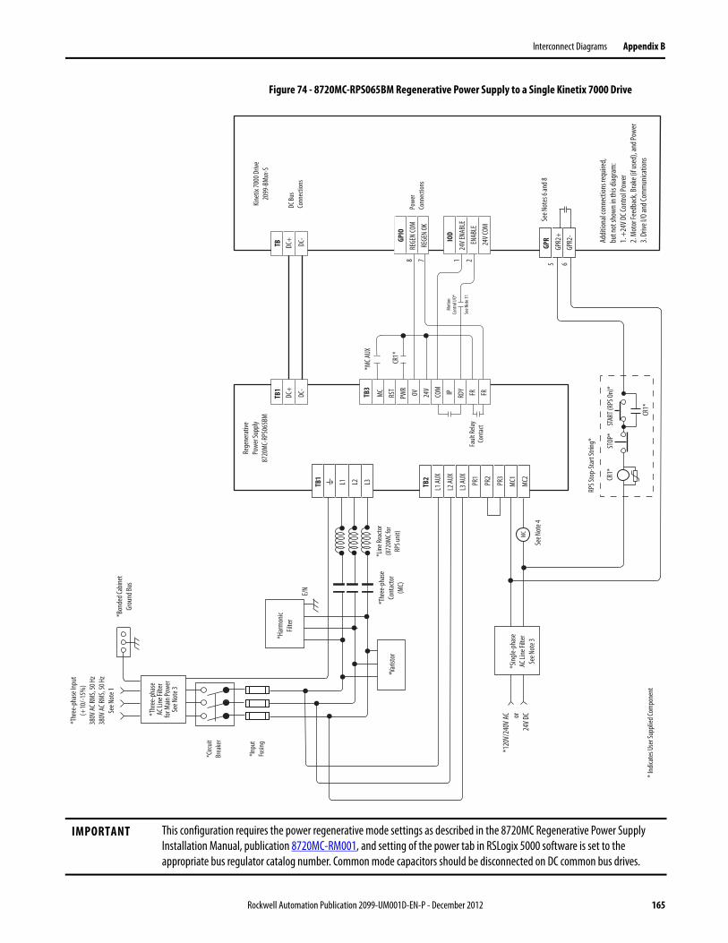
Interconnect Diagrams Appendix B
Figure 74 - 8720MC-RPS065BM Regenerative Power Supply to a Single Kinetix 7000 Drive
IMPORTANT This configuration requires the power regenerative mode settings as described in the 8720MC Regenerative Power Supply Installation Manual, publication 8720MC-RM001, and setting of the power tab in RSLogix 5000 software is set to the appropriate bus regulator catalog number. Common mode capacitors should be disconnected on DC common bus drives.
L1 L2 L3TB1
L1 AU
X
L2 AU
X
L3 AU
X
PR1
PR2
PR3
MC1
MC2
TB2
GPR2
+
GPR
E/N
5 6
STOP
*ST
ART (
RPS O
n)*
CR1*
CR1*
MC
TB1
DC+
DC-
MC
RST
PWR
0V 24V
COM IP RDY FR FRTB3
8 7RE
GEN
COM
REGE
N OK
GPIO
CR1*
DC Bu
s Co
nnec
tions
*MC A
UX
24V E
NABL
EEN
ABLE
24V C
OM
IOD
1 2
Powe
rCo
nnec
tions
Faul
t Rela
yCo
ntac
t
GPR2
-
TB DC+ DC-
RPS S
top-
Star
t Stri
ng*
*120
V/24
0V A
C or24
V DC
* Ind
icate
s Use
r Sup
plied
Com
pone
nt
*Bon
ded C
abine
tGr
ound
Bus
*Var
istor
*Thr
ee-p
hase
AC Li
ne Fi
lter
for M
ain Po
wer
See N
ote 3
*Har
mon
icFil
ter
*Sin
gle-p
hase
AC Li
ne Fi
lter
See N
ote 3
*Line
Reac
tor
(872
0MC f
orRP
S unit
)
*Thr
ee-p
hase
Inpu
t(+
10/-1
5%)
380V
AC RM
S, 50
Hz
380V
AC RM
S, 50
Hz
See N
ote 1
*Thr
ee-p
hase
Cont
acto
r(M
C)
*Circ
uitBr
eake
r
*Inpu
tFu
sing
Rege
nera
tive
Powe
r Sup
ply87
20M
C-RP
S065
BMKin
etix
7000
Driv
e20
99-B
Mxx
-S
Addit
ional
conn
ectio
ns re
quire
d,bu
t not
show
n in t
his di
agra
m:
1. +
24V D
C Con
trol P
ower
2. M
otor
Feed
back
, Bra
ke (i
f use
d), a
nd Po
wer
3. Dr
ive I/
O an
d Com
mun
icatio
ns
See N
ote 4
See N
otes
6 an
d 8
Mot
ionCo
ntro
l I/O*
See N
ote 1
1
Rockwell Automation Publication 2099-UM001D-EN-P - December 2012 165
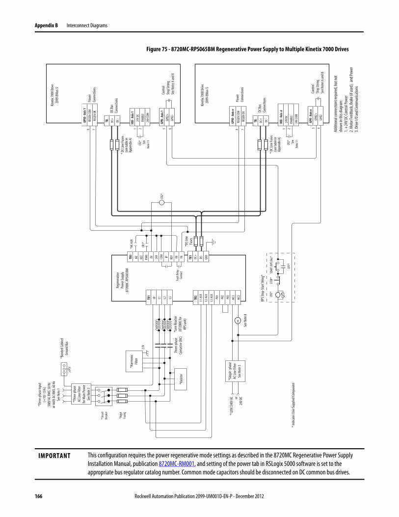
Appendix B Interconnect Diagrams
Figure 75 - 8720MC-RPS065BM Regenerative Power Supply to Multiple Kinetix 7000 Drives
IMPORTANT This configuration requires the power regenerative mode settings as described in the 8720MC Regenerative Power Supply Installation Manual, publication 8720MC-RM001, and setting of the power tab in RSLogix 5000 software is set to the appropriate bus regulator catalog number. Common mode capacitors should be disconnected on DC common bus drives.
2 5 68 7 2 5 68 7
L1 L2 L3TB1
L1 AU
X
L2 AU
X
L3 AU
X
PR1
PR2
PR3
MC1
MC2
TB2
TB1
DC+
DC-
GND
DC+
DC-
TB 24V D
CEN
ABLE
24V C
OM
IOD
- Axi
s 1
GPR2
+GP
R2-
GPR
- Axi
s 1
REGE
N CO
M
REGE
N OK
GPIO
- Axi
s 1
DC+
DC-
TB GPR2
+GP
R2-
GPR
- Axi
s n
REGE
N CO
M
REGE
N OK
GPIO
- Axi
s n
24V D
CEN
ABLE
24V C
OM
IOD
- Axi
s n
STOP
*ST
ART (
RPS O
n)*
CR1*
CR1*
CR1*
MC
E/N
1 1
CR2* Se
eNo
te 11 CR2* Se
eNo
te 11
RPS S
top-
Star
t Stri
ng*
Rege
nera
tive
Powe
r Sup
ply87
20M
C-RP
S065
BM
*120
V/24
0V AC or
24V D
C
* Ind
icate
s Use
r Sup
plied
Com
pone
nt
Thre
e-ph
ase
Cont
acto
r (M
C)
*Bon
ded C
abin
etGr
ound
Bus
*Har
mon
icFil
ter
*Var
istor
Cont
rol
Stop
Strin
gSe
e Not
es 6
and 8
DC Bu
sCo
nnec
tions
Powe
rCo
nnec
tions
DC Bu
sCo
nnec
tions
Powe
rCo
nnec
tions
*Sin
gle- p
hase
AC Li
ne Fi
lter
See N
ote 3
Kinet
ix 70
00 D
rive
2099
-BMxx
-S
*DC L
ineFu
ses
*Line
Reac
tor
(872
0MC f
orRP
S unit
)
*Thr
ee-p
hase
AC Li
ne Fi
lter
for M
ain Po
wer
See N
ote 3
* DC L
ine Fu
ses
(see t
able
inAp
pend
ix A)
* DC L
ine Fu
ses
(see t
able
inAp
pend
ix A)
MC
RST
PWR
0V 24V
COM IP RDY FR FRTB3
Faul
t Rela
yCo
ntac
t
*MC A
UX
*Circ
uitBr
eake
r
*Inpu
tFu
sing
*Thr
ee-p
hase
Inpu
t(+
10/-1
5%)
380V
AC RM
S, 50
Hz
or 46
0V AC
RMS,
60 H
zSe
e Not
e 1
Addit
ional
conn
ectio
ns re
quire
d, bu
t not
show
n in t
his di
agra
m:
1. +
24V D
C Con
trol P
ower
2. M
otor
Feed
back
, Bra
ke (i
f use
d), a
nd Po
wer
3. Dr
ive I/
O an
d Com
mun
icatio
ns
Cont
rol
Stop
Strin
gSe
e Not
es 6
and 8
Kinet
ix 70
00 D
rive
2099
-BMxx
-S
See N
ote 4
CR2*
166 Rockwell Automation Publication 2099-UM001D-EN-P - December 2012

Interconnect Diagrams Appendix B
Figure 76 - Dual 8720MC-RPS065Bx Regenerative Power Supplies to a Single Kinetix 7000 Drive
IMPORTANT This configuration requires the power regenerative mode settings as described in the 8720MC Regenerative Power Supply Installation Manual, publication 8720MC-RM001, and setting of the power tab in RSLogix 5000 software is set to the appropriate bus regulator catalog number. Common mode capacitors should be disconnected on DC common bus drives.
DC+
DC-
TB 24V D
CEN
ABLE
IOD
5 6GP
R2+
GPR
8 7RE
GEN
COM
REGE
N OK
GPIO
STOP
*ST
ART (
RPS O
n)*
CR1*
L1 L2 L3TB1
L1 AU
X
L2 AU
X
L3 AU
X
PR1
PR2
PR3
MC1
MC2
TB2
TB1
DC+
DC-
L1 L2 L3TB1
L1 AU
X
L2 AU
X
L3 AU
X
PR1
PR2
PR3
MC1
MC2
TB2
TB1
DC+
DC-
1 2
E/N
E/N
P N MC1
*M
CRST
PWR
0V 24V
COM IP RDY FR FRTB3
Addit
ional
conn
ectio
ns re
quire
d,bu
t not
show
n in t
his di
agra
m:
1. +
24V D
C Con
trol P
ower
2. M
otor
Feed
back
, Bra
ke (i
f use
d),
an
d Pow
er3.
Drive
I/O
and C
omm
unica
tions
CR1*
GPR2
-
CR1* M
C2*
CB2*
Bond
ed Ca
binet
Grou
nd Bu
s*
Circu
itBr
eake
r (CB
2)*
Inpu
t Fu
sing*
See N
ote 2
Thre
e-ph
ase
Cont
acto
r (M
C2)
Harm
onic
Filte
r*
Varis
tor*
* Ind
icate
s Use
r Sup
plied
Com
pone
nt
*120
V/24
0V AC or
24V D
CM
C2
Thre
e-ph
ase
Cont
acto
r (M
C1)
Harm
onic
Filte
r*
Varis
tor*
Single
-pha
seCo
ntac
tor
See N
ote 4
Fault
Relay
Cont
act
DC Bu
sCo
nnec
tions
Kinet
ix 70
00 D
rive
2099
-BMxx
-SAx
is n
Cont
rol
Stop
Strin
gSe
e Not
es 6
and 8
Digit
al I/O
an
d Pow
erCo
nnec
tions
DC Li
neFu
ses*
DC Li
neFu
ses*
120V
AC
or 24V D
C*
RPS S
top-
Star
t Stri
ng
DC Bu
s Co
nnec
tions
*Line
Reac
tor
(872
0MC f
orRP
S unit
)
*DC L
ine Fu
ses
(see t
able
inAp
pend
ix A)
*Line
Reac
tor
(872
0MC f
orRP
S unit
)
*Thr
ee-p
hase
Inpu
t(+
10/-1
5%)
380V
AC RM
S, 50
Hz
or 46
0V AC
RMS,
60 H
zSe
e Not
e 1
Thre
e-ph
ase A
C Lin
e Filt
er fo
rM
ain Po
wer*
See N
ote 3
Bond
ed Ca
binet
Grou
nd Bu
s*
Circu
itBr
eake
r (CB
1)*
Inpu
t Fu
sing*
See N
ote 2
Thre
e-ph
ase
AC Li
ne Fi
lter
for M
ain Po
wer*
Singl
e-ph
ase
AC Li
ne Fi
lter*
Singl
e-ph
ase
Cont
acto
r*Se
e Not
e 4
MC1
Slave
Rege
nera
tive
Powe
r Sup
ply
8720
MC-
RPS0
65BS
Mas
ter
Rege
nera
tive
Powe
r Sup
ply
8720
MC-
RPS0
65BM
PIFS CN2 PIFS CN3
See N
ote 1
0
CB2*
Mot
ionCo
ntro
l I/O*
See N
ote 1
1
Rockwell Automation Publication 2099-UM001D-EN-P - December 2012 167

Appendix B Interconnect Diagrams
Figure 77 - Kinetix 7000 Drive AC Powered with a 8720MC-RPS190BM Regenerative Power Supply
IMPORTANT This configuration requires the power regenerative mode settings as described in the 8720MC Regenerative Power Supply Installation Manual, publication 8720MC-RM001, and setting of the power tab in RSLogix 5000 software is set to the appropriate bus regulator catalog number. Common mode capacitors should be disconnected on DC common bus drives.
STOP
*ST
ART (
Drive
Main
Powe
r On)
*
CR2*
CR2*
CR2*
M1*
Note
4
5 6
TBREGE
N CO
MRE
GEN
OK
GPIO
DC+
DC-
TB GPR2
+GP
R
L1 L2 L3GPR2
-
Drive
Stop
-Sta
rt St
ring*
*120
V AC/
240V
AC or24
V DC
* Sing
le-ph
ase
AC Li
ne
Filte
r
Kinet
ix 70
00 D
rive
2099
-BMxx
-S
DC Bu
s Co
nnec
tions Co
ntro
l St
op St
ring
See N
ote 8
AC In
put
Conn
ectio
ns
24V
ENAB
LEEN
ABLE
IOD Ad
dition
al co
nnec
tions
requ
ired,
but n
ot sh
own i
n this
diag
ram
:1.
+24
V DC C
ontro
l Pow
er2.
Mot
or Fe
edba
ck, B
rake
(if u
sed)
,
and P
ower
3. Dr
ive I/
O an
d Com
mun
icatio
ns
Powe
rCo
nnec
tions
*Mot
ion Co
ntro
lSt
op-S
tart
Strin
g(fr
om PL
C or o
ther
cont
rol s
tring
)
L1 L2 L3TB1
TB1
DC+
DC-
CR1*
L1 L2 L3TB1
L4 L5 L6TB1
L1 AU
X
L2 AU
X
L3 AU
X
PR1
PR2
PR3
TB2
MC
RST
PWR
0V 24V
COM IP RDY FR FRTB3
Fault
Relay
Cont
act
L1 L2 L3
L4 L5 L6
RED
BLK
YLW
Fan 2
CN1 A1 A2 A3 A4 A5 B1 B2 B3 B4 B5CN2 A1 A2 A3 A4 A5 B1 B2 B3 B4 B5 CN4 1 2 3
+24
V3
0V3
SENS
+24
V2
0V2
MC1
TB4
MC2
R1 S1 T1
MC1
MC2
+24
V2 0V2 NC
+24
V3 0V3
SENS
-out
+24
V MC
RED
WHT
BLU
RED
BLK
YLW
*Circ
uitBr
eake
rSe
e Not
e 2
*Inpu
tFu
sing
See N
ote 2
Rege
nera
tive
Powe
r Sup
ply87
20M
C-RP
S190
BM DC Bu
sCo
nnec
tions
Line R
eacto
r87
20M
C-LR
10-1
00B
EMC L
ine Fi
lter
8720
MC-
EF19
0-VB
*Thr
ee-p
hase
Inpu
t (+
10/-1
5%)
380V
AC RM
S, 50
Hz o
r 460
V AC R
MS,
60 H
zSe
e Not
e 1
L1 L2 L3
L4 L5 L6
Fan 3
Line R
eacto
r87
20M
C-LR
10-1
00B
M1*
Mot
ionCo
ntro
l I/O
See N
ote 1
1 PE R S T
*Bon
ded C
abin
etGr
ound
Bus
* Ind
icate
s Use
r Sup
plied
Com
pone
nt
*Lin
e Rea
ctor
(132
1-3R
type
, 3%
com
patib
lewi
th Ki
netix
7000
drive
)
*Thr
ee-p
hase
Cont
acto
r(M
1 in C
ontro
l Stri
ng)
*Thr
ee-p
hase
AC Li
ne Fi
lter
360°
Shiel
ding o
f Pow
er W
iring
Requ
ired t
o Com
ply w
ithEM
C Req
uirem
ents
*Inpu
tFu
sing
See N
ote 3
STOP
*ST
ART (
RPS O
n)*
CR1*
CR1*
*120
V AC
or 24
V DC
M1*
RPS S
top-
Star
t Stri
ng*
168 Rockwell Automation Publication 2099-UM001D-EN-P - December 2012

Interconnect Diagrams Appendix B
Figure 78 - 8720MC-RPS190BM Regenerative Power Supply to a Single Kinetix 7000 Drive
IMPORTANT This configuration requires the power regenerative mode settings as described in the 8720MC Regenerative Power Supply Installation Manual, publication 8720MC-RM001, and setting of the power tab in RSLogix 5000 software is set to the appropriate bus regulator catalog number. Common mode capacitors should be disconnected on DC common bus drives.
L1 L2 L3TB1
TB1
DC+
DC-
DC+
DC-
TB
1 224
V DC
ENAB
LE24
V COM
IOD
5 6GP
R2+
GPR2
-
GPR
8 7RE
GEN
COM
RE
GEN
OK
GPIO
CR1*
L1 L2 L3TB1
L4 L5 L6TB1
STOP
*CR
1*
CR1*
L1 AU
X
L2 AU
X
L3 AU
X
PR1
PR2
PR3
TB2
STAR
T (RP
S On)
*MC
RST
PWR
0V 24V
COM IP RDY FR FRTB3
Fault
Relay
Cont
act
L1 L2 L3
L4 L5 L6
RED
BLK
YLW
Fan 2
CN1 A1 A2 A3 A4 A5 B1 B2 B3 B4 B5CN2 A1 A2 A3 A4 A5 B1 B2 B3 B4 B5 CN4 1 2 3
+24
V3
0V3
SENS
+24
V2
0V2
MC1
TB4
MC2
R1 S1 T1
MC1
MC2
+24
V2 0V2 NC
+24
V3 0V3
SENS
-out
+24
V MC
RED
WHT
BLU
RED
BLK
YLW
*Circ
uitBr
eake
rSe
e N\o
te 2
*Inpu
tFu
sing
See N
ote 2
Rege
nera
tive
Powe
r Sup
ply87
20M
C-RP
S190
BM DC Bu
sCo
nnec
tions
Kinet
ix 70
00 D
rive
2099
-BMxx
-SAx
is n
120V
/240
V AC
or24
V DC
RPS S
top-
Star
t Stri
ng
Line R
eacto
r87
20M
C-LR
10-1
00B
EMC L
ine Fi
lter
8720
MC-
EF19
0-VB
* Ind
icate
s Use
r Sup
plied
Com
pone
nt
DC Bu
sCo
nnec
tions
*Sin
gle-
phas
e AC
Line
Filte
r
*Thr
ee-p
hase
Inpu
t(+
10/-1
5%)
380V
AC RM
S, 50
Hz
or 46
0V AC
RMS,
60 H
zSe
e Not
e 1
Addit
ional
conn
ectio
ns re
quire
d, bu
t not
show
n in t
his di
agra
m:
1. +
24V D
C Con
trol P
ower
2. M
otor
Feed
back
, Bra
ke (i
f use
d), a
nd Po
wer
3. Dr
ive I/
O an
d Com
mun
icatio
ns
See N
otes
6 an
d 8
L1 L2 L3
L4 L5 L6
Fan 3
Line R
eacto
r87
20M
C-LR
10-1
00B
Mot
ionCo
ntro
l I/O
See N
ote 1
1
Rockwell Automation Publication 2099-UM001D-EN-P - December 2012 169

Appendix B Interconnect Diagrams
Figure 79 - 8720MC-RPS190BM Regenerative Power Supply to Multiple Kinetix 7000 Drives
IMPORTANT This configuration requires the power regenerative mode settings as described in the 8720MC Regenerative Power Supply Installation Manual, publication 8720MC-RM001, and setting of the power tab in RSLogix 5000 software is set to the appropriate bus regulator catalog number. Common mode capacitors should be disconnected on DC common bus drives.
L1 L2 L3TB1
TB1
DC+
DC-
L1 L2 L3TB1
L4 L5 L6TB1
L1 AU
X
L2 AU
X
L3 AU
X
PR1
PR2
PR3
TB2
MC
RST
PWR
0V 24V
COM IP RDY FR FRTB3
Fault
Relay
Cont
act
L1 L2 L3
L4 L5 L6
RED
BLK
YLW
Fan 2
CN1 A1 A2 A3 A4 A5 B1 B2 B3 B4 B5CN2 A1 A2 A3 A4 A5 B1 B2 B3 B4 B5 CN4 1 2 3
+24
V3
0V3
SENS
+24
V2
0V2
MC1
TB4
MC2
R1 S1 T1
MC1
MC2
+24
V2 0V2 NC
+24
V3 0V3
SENS
-out
+24
V MC
RED
WHT
BLU
RED
BLK
YLW
GND
*Circ
uitBr
eake
rSe
e N\o
te 2
*Inpu
tFu
sing
See N
ote 2
Rege
nera
tive
Powe
r Sup
ply87
20M
C-RP
S190
BM DC Bu
sCo
nnec
tions
120V
/240
V AC
or24
V DCLin
e Rea
ctor
8720
MC-
LR10
-100
B
EMC L
ine Fi
lter
8720
MC-
EF19
0-VB
* Ind
icate
s Use
r Sup
plied
Com
pone
nt
*Sin
gle-
phas
e AC
Line
Filte
r
*Thr
ee-p
hase
Inpu
t(+
10/-1
5%)
380V
AC RM
S, 50
Hz
or 46
0V AC
RMS,
60 H
zSe
e Not
e 1
L1 L2 L3
L4 L5 L6
Fan 3
Line R
eacto
r87
20M
C-LR
10-1
00B
*DC L
ineFu
ses
28 7 28 7
DC+
DC-
TB 24V D
CEN
ABLE
24V C
OM
IOD
- Axi
s 1
GPR2
+GP
R2-
GPR
- Axi
s 1
REGE
N CO
M
REGE
N OK
GPIO
- Axi
s 1
DC+
DC-
TB GPR2
+GP
R2-
GPR
- Axi
s n
REGE
N CO
M
REGE
N OK
GPIO
- Axi
s n
24V D
CEN
ABLE
24V C
OM
IOD
- Axi
s n
1 1
CR2* Se
eNo
te 11 CR2* Se
eNo
te 11
Cont
rol
Stop
Strin
gSe
e Not
es 6
and 8
DC Bu
sCo
nnec
tions
Powe
rCo
nnec
tions
DC Bu
sCo
nnec
tions
Powe
rCo
nnec
tions
Kinet
ix 70
00 D
rive
2099
-BMxx
-S* D
C Line
Fuse
s(se
e tab
le in
Appe
ndix
A)
* DC L
ine Fu
ses
(see t
able
inAp
pend
ix A)
Addit
ional
conn
ectio
ns re
quire
d, bu
t not
show
n in t
his di
agra
m:
1. +
24V D
C Con
trol P
ower
2. M
otor
Feed
back
, Bra
ke (i
f use
d), a
nd Po
wer
3. Dr
ive I/
O an
d Com
mun
icatio
ns
Cont
rol
Stop
Strin
gSe
e Not
es 6
and 8
Kinet
ix 70
00 D
rive
2099
-BMxx
-S
5 6 5 6
STOP
*ST
ART (
RPS O
n)*
CR1*
CR1*
RPS S
top-
Star
t Stri
ng*
CR1*
CR2*
170 Rockwell Automation Publication 2099-UM001D-EN-P - December 2012
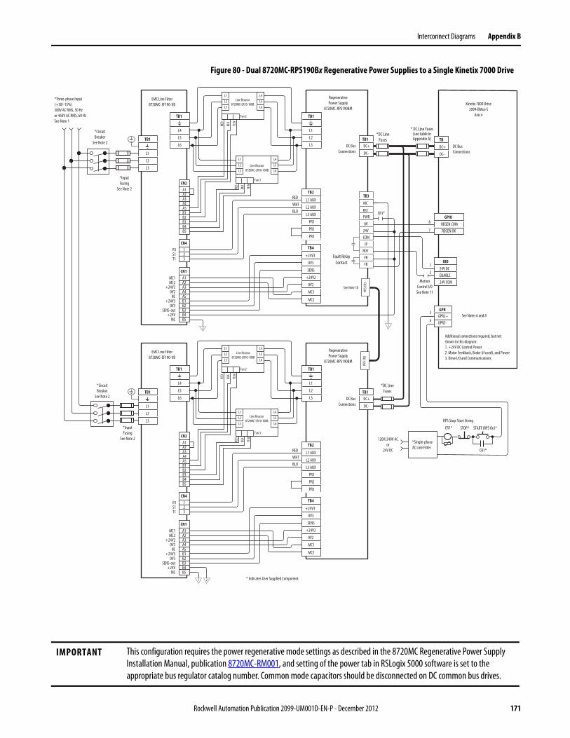
Interconnect Diagrams Appendix B
Figure 80 - Dual 8720MC-RPS190Bx Regenerative Power Supplies to a Single Kinetix 7000 Drive
IMPORTANT This configuration requires the power regenerative mode settings as described in the 8720MC Regenerative Power Supply Installation Manual, publication 8720MC-RM001, and setting of the power tab in RSLogix 5000 software is set to the appropriate bus regulator catalog number. Common mode capacitors should be disconnected on DC common bus drives.
L1
L2
L3
TB1
TB1DC+
DC-DC+
DC-
TB
1
224V DCENABLE24V COM
IOD
5
6GPR2+GPR2-
GPR
8
7REGEN COM REGEN OK
GPIOCR1*
L1
L2
L3
TB1
L4
L5
L6
TB1
L1 AUX
L2 AUX
L3 AUX
PR1
PR2
PR3
TB2
MC
RSTPWR
0V24VCOM
IPRDY
FRFR
TB3
Fault RelayContact
L1
L2
L3
L4
L5
L6
RED
BLK
YLW
Fan 2
CN1A1A2A3A4A5B1B2B3B4B5
CN2A1A2A3A4A5B1B2B3B4B5
CN4123
+24V3
0V3
SENS
+24V2
0V2
MC1
TB4
MC2
R1S1T1
MC1MC2
+24V20V2
NC+24V3
0V3SENS-out
+24VMC
RED
WHT
BLU
RED
BLK
YLW
2
1
1
*CircuitBreaker
See Note 2
*InputFusing
See Note 2
RegenerativePower Supply
8720MC-RPS190BM
DC BusConnections
Kinetix 7000 Drive2099-BMxx-S
Axis n
EMC Line Filter8720MC-EF190-VB
* Indicates User Supplied Component
DC BusConnections
*Three-phase Input(+10/-15%)380V AC RMS, 50 Hzor 460V AC RMS, 60 HzSee Note 1
Additional connections required, but notshown in this diagram:1. +24V DC Control Power2. Motor Feedback, Brake (if used), and Power3. Drive I/O and Communications
See Notes 6 and 8
L1
L2
L3
L4
L5
L6
Fan 3
MotionControl I/O
See Note 11
L1
L2
L3
TB1
TB1DC+
DC-L1
L2
L3
TB1
L4
L5
L6
TB1
L1 AUX
L2 AUX
L3 AUX
PR1
PR2
PR3
TB2
L1
L2
L3
L4
L5
L6
RED
BLK
YLW
Fan 2
CN1A1A2A3A4A5B1B2B3B4B5
CN2A1A2A3A4A5B1B2B3B4B5
CN4123
+24V3
0V3
SENS
+24V2
0V2
MC1
TB4
MC2
R1S1T1
MC1MC2
+24V20V2
NC+24V3
0V3SENS-out
+24VMC
RED
WHT
BLU
RED
BLK
YLW
RegenerativePower Supply
8720MC-RPS190BM
DC BusConnections
Line Reactor8720MC-LR10-100B
EMC Line Filter8720MC-EF190-VB
L1
L2
L3
L4
L5
L6
Fan 3STOP*CR1*
CR1*
START (RPS On)*
120V/240V ACor
24V DC
RPS Stop-Start String
*Single-phase AC Line Filter
Line Reactor8720MC-LR10-100B
Line Reactor8720MC-LR10-100B
Line Reactor8720MC-LR10-100B
*CircuitBreaker
See Note 2
*InputFusing
See Note 2
2
*DC LineFuses
* DC Line Fuses(see table inAppendix A)
*DC LineFuses
PIFS
CN3
PIFS
CN2
See Note 10
Rockwell Automation Publication 2099-UM001D-EN-P - December 2012 171

Appendix B Interconnect Diagrams
Kinetix 7000 Drive/Rotary Motor Wiring Examples
Figure 81 - Motors with High Resolution Feedback (Bayonet Style Connector)
IMPORTANT The Bulletin MPL motor wiring example on this page applies to motors equipped with bayonet connectors.
D
CB
A
W
V
U
4
3
2
1
Green/Yellow
1/Blue
2/Black
3/Brown
GNDWVU
BR+
BR-
A
C3
2
4
1
Black
WhiteGPR1-
GPR1+
COM
24VDC
SIN+SIN-
COS+COS-
DATA+DATA-
GREENWHT/GREEN
BLACKWHT/BLACK
REDWHT/RED
+9VDCTS+
ORANGEWHT/ORANGE
CDEF
AB
KL
S
P
NR
12
34
5101467
11
Dashed lines denotean internal circuit
K
ECOM WHT/GRAY
Motor Brake (2)
General Purpose Relay(GPR) Connector
Motor Power(MP) Connector
Cable ShieldClamp
Cable shield clamp must be used to meet CE requirements. No external connection to ground required. (3)
MPL-Bxx460V Servo Motors with High
Resolution Feedback
Motor Feedback(MF) Connector (3)
Motor Power (Three-phase) (2)
Motor Feedback (2)
Thermostat
Kinetix 7000 Drive
Customer-supplied24V DC (2A max) (1)
2090-XXxPMP-xxSxxMotor Power Cable
2090-UXxBMP-18Sxx Brake Cable
2090-XXxFMP-Sxx (flying lead) or
2090-UXNFMP-Sxx(premolded backshell)
Motor Connector Shell
Motor Connector Shell
(1) See Customer-supplied 24V DC Power Supply Notes on page 173 for important wiring information.(2) See MP-Series (Bulletin MPL) Motor Connectors on page 83 for more information on bayonet and circular DIN connectors.(3) See Wire Low-profile Connectors on page 98 for more information on grounding feedback cables when using low-profile connectors.
2090-K6CK-D15M connector kit
172 Rockwell Automation Publication 2099-UM001D-EN-P - December 2012
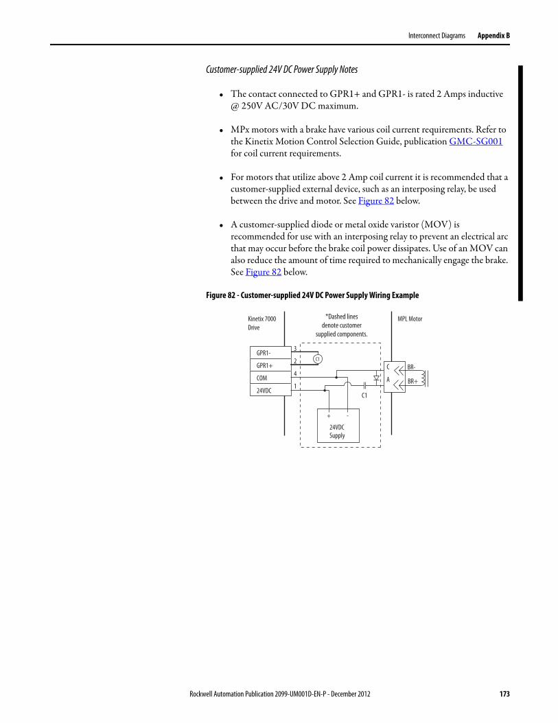
Interconnect Diagrams Appendix B
Customer-supplied 24V DC Power Supply Notes
• The contact connected to GPR1+ and GPR1- is rated 2 Amps inductive @ 250V AC/30V DC maximum.
• MPx motors with a brake have various coil current requirements. Refer to the Kinetix Motion Control Selection Guide, publication GMC-SG001 for coil current requirements.
• For motors that utilize above 2 Amp coil current it is recommended that a customer-supplied external device, such as an interposing relay, be used between the drive and motor. See Figure 82 below.
• A customer-supplied diode or metal oxide varistor (MOV) is recommended for use with an interposing relay to prevent an electrical arc that may occur before the brake coil power dissipates. Use of an MOV can also reduce the amount of time required to mechanically engage the brake. See Figure 82 below.
Figure 82 - Customer-supplied 24V DC Power Supply Wiring Example
BR+
BR-
A
C
3
2
4
1
GPR1-
GPR1+
COM
24VDC
24VDCSupply
+ -
C1
C1
*Dashed linesdenote customer
supplied components.
Kinetix 7000Drive
MPL Motor
Rockwell Automation Publication 2099-UM001D-EN-P - December 2012 173

Appendix B Interconnect Diagrams
Figure 83 - Motors with High Resolution Feedback (Circular DIN Style Connector)
IMPORTANT The Bulletin MPL motor wiring example on this page applies to motors equipped with circular DIN connectors.
D/
C/WB/V
A/U
W
V
U
4
3
2
1
Green/Yellow
Blue
Black
Brown
GNDWVU
BR+
BR-
F/+
G/-3
2
4
1
Black
WhiteGPR1-
GPR1+
COM
24VDC
SIN+SIN-
COS+COS-
DATA+DATA-
GREENWHT/GREEN
BLACKWHT/BLACK
REDWHT/RED
+9VDCTS+
ORANGEWHT/ORANGE
3456
12
910
14
12
1113
12
34
5101467
11
Dashed lines denotean internal circuit
K
ECOM WHT/GRAY
TS-
COM
BLUE
Shield
Motor Brake (2)
General Purpose Relay(GPR) Connector
Motor Power(MP) Connector
Cable ShieldClamp
Cable shield clamp must be used to meet CE requirements. No external connection to ground required.
MPL-Bxx and MPM-Bxx460V Servo Motors with High
Resolution Feedback
Motor Feedback(MF) Connector (3)
Motor Power (Three-phase) (2)
Motor Feedback (2)
Thermostat
Kinetix 7000 Drive
Customer-supplied24V DC (2A max) (1)
Motor Connector Shell
(1) See Customer-supplied 24V DC Power Supply Notes on page 173 for important wiring information.(2) See MP-Series (Bulletin MPL) Motor Connectors on page 83 for more information on bayonet and circular DIN connectors.(3) See Wire Low-profile Connectors on page 98 for more information on grounding feedback cables when using low-profile connectors.
2090-CPBM7DF-xxAAxx, or2090-XXNPMF-xxSxx (standard, non-flex)
or 2090-CPBM7DF-xxAFxx (continuous-flex)
Motor Power Cable
2090-CFBM7DF-CEAAxx, or2090-XXNFMF-Sxx (standard, non-flex) or2090-CFBM7DF-CEAFxx (continuous-flex)
Flying-lead Feedback Cable
2090-K6CK-D15M connector kit
174 Rockwell Automation Publication 2099-UM001D-EN-P - December 2012
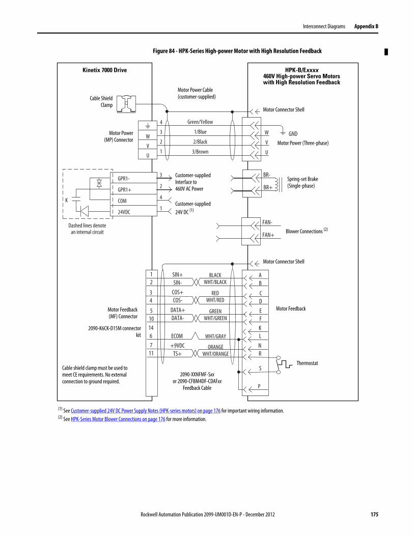
Interconnect Diagrams Appendix B
Figure 84 - HPK-Series High-power Motor with High Resolution Feedback
SIN+SIN-
COS+COS-
DATA+DATA-
GREENWHT/GREEN
ECOM WHT/GRAY
BLACKWHT/BLACK
REDWHT/RED
+9VDCTS+
ORANGEWHT/ORANGE
CDEF
AB
KL
S
P
NR
12
34
5101467
11
W
V
U
4
3
2
1
GNDW
V
U
FAN+
FAN-
3
2
4
1
BR+
BR-
Dashed lines denotean internal circuit
K
GPR1-
GPR1+
COM
24VDC
Green/Yellow
1/Blue
2/Black
3/Brown
Motor Power(MP) Connector
Motor Feedback(MF) Connector
Motor Feedback
Thermostat
Motor Power Cable (customer-supplied)
2090-XXNFMF-Sxxor 2090-CFBM4DF-CDAFxx
Feedback Cable
Cable ShieldClamp
Spring-set Brake (Single-phase)
Customer-supplied Interface to460V AC Power
Customer-supplied 24V DC (1)
HPK-B/Exxxx460V High-power Servo Motors with High Resolution Feedback
Kinetix 7000 Drive
Motor Connector Shell
Motor Connector Shell
Motor Power (Three-phase)
Cable shield clamp must be used to meet CE requirements. No external connection to ground required.
(1) See Customer-supplied 24V DC Power Supply Notes (HPK-series motors) on page 176 for important wiring information.(2) See HPK-Series Motor Blower Connections on page 176 for more information.
Blower Connections (2)
2090-K6CK-D15M connectorkit
Rockwell Automation Publication 2099-UM001D-EN-P - December 2012 175

Appendix B Interconnect Diagrams
Customer-supplied 24V DC Power Supply Notes (HPK-series motors)
• HPK-series motors require a customer-supplied 460V AC single-phase supply, rather than a 24V DC supply. However, the brake current ratings required by HPK-series motors are higher than the contact rating of the GPR connector. Therefore, if using an HPK-series motor with a brake, it is recommended that a customer-supplied, external interposing relay or equivalent circuit be used. See Figure 85 below.
• The contact connected to GPR1+ and GPR1- is rated 2 Amps inductive @ 250V AC/30 VDC maximum.
• See the Kinetix Motion Control Selection Guide, publicationGMC-SG001 for HPK-series motor brake ratings.
Figure 85 - Customer-supplied HPK-Series Motor Brake Wiring Example
HPK-Series Motor Blower Connections
• The HPK-series motor blower must be used to ensure proper motor performance.
• The blower connections can use either a Star (460 V AC) or Delta (230V AC) three-phase configuration. See the HPK-Series Asynchronous Servo Motor Installation Instructions, publication HPK-IN001, for connection diagrams.
• HPK-series Motors with a brake and without a brake have different blower assemblies and, therefore, have different connection and electrical characteristics.
• The HPK-series motor has a conduit box with terminals/leads for external power connections.
• See the Kinetix Motion Control Selection Guide, publicationGMC-SG001 for HPK-series motors blower voltage and current specifications.
BR+
BR-
A
C
3
2
4
1
GPR1-
GPR1+
COM
24VDC
24V DCSupply
+ -
C1 C1
*Dashed linesdenote customer
supplied components.
L1 L2
Kinetix 7000Drive
HPK-Series Motor
460V ACSupply
176 Rockwell Automation Publication 2099-UM001D-EN-P - December 2012

Interconnect Diagrams Appendix B
Figure 86 - Example with RDD-Series (Bulletin RDB-B) Motors
C/WB/V
A/U
W
V
U
SIN+SIN-COS+COS-
DATA+DATA-
+5VDCECOM
GREENWHT/GREEN
GRAYWHT/GRAY
BLACKWHT/BLACK
REDWHT/RED
34
56
12
910
12
34
91078
14
12
ORANGEWHT/ORANGE
1113 11
4
3
2
1
Green/Yellow
Blue
Black
Brown
GND
Shield
WVU
TS-
COM
BLUE
78
56
CLK+CLK-
BROWNWHT/BROWN
–TS+
Motor Power(MP) Connector
Cable ShieldClamp
RDB-Bxxxx Direct DriveServo Motors with
High Resolution Feedback
Motor Feedback(MF) Connector
Three-phaseMotor Power
MotorFeedback
Thermistor
2090-K7CK-KENDATFeedback Module
Refer to table on page 162 for note information.
2090-XXNFMF-Sxx (standard, non-flex) or2090-CFBM7DF-CDAFxx (continuous-flex)
Flying-lead Feedback Cable
2090-CPWM7DF-xxAAxx, or2090-XXNPMF-xxSxx(standard, non-flex)
or 2090-CPWM7DF-xxAFxx (continuous-flex)
Motor Power Cable
Kinetix 7000 Drive
Cable shield clamp must be used in order to meet CE requirements. No external connection to ground is required.
Rockwell Automation Publication 2099-UM001D-EN-P - December 2012 177

Appendix B Interconnect Diagrams
Kinetix Safe-off Feature Block Diagram
Kinetix 7000 drives with the Safe-off feature installed ship with the wiring header and a motion-allowed jumper installed. In this configuration, the safe-off feature is disabled (not used).
Figure 87 - Kinetix Safe-off Feature
K1
K2
K1-A
K2-A
K2-C
K1-C
+24V
M
Safe-Off Option
6
5
7
34
12
89
Wiring Header
Motion Allowed Jumper
Gate ControlPower Supply
Safety MonitoruC
Gate ControlEnable Signal
+24V_COM
FDBK1+FDBK1-
ENABLE-
ENABLE1+
ENABLE2+
FDBK2+FDBK2-
Gate ControlCircuit (CCP)
+24V
Safe-Off (SO)9-pin Connector
DRIVE ENABLE+24V_COM
178 Rockwell Automation Publication 2099-UM001D-EN-P - December 2012
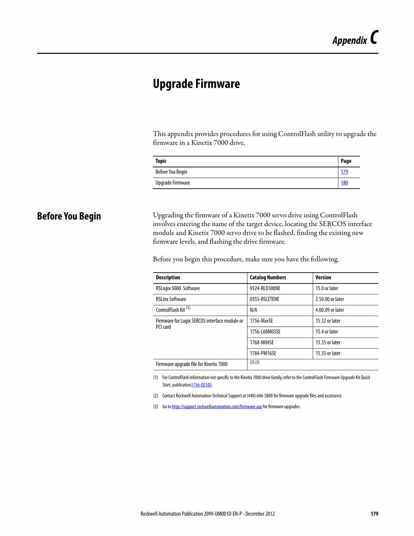
Appendix C
Upgrade Firmware
This appendix provides procedures for using ControlFlash utility to upgrade the firmware in a Kinetix 7000 drive.
Before You Begin Upgrading the firmware of a Kinetix 7000 servo drive using ControlFlash involves entering the name of the target device, locating the SERCOS interface module and Kinetix 7000 servo drive to be flashed, finding the existing new firmware levels, and flashing the drive firmware.
Before you begin this procedure, make sure you have the following.
Topic Page
Before You Begin 179
Upgrade Firmware 180
Description Catalog Numbers Version
RSLogix 5000 Software 9324-RLD300NE 15.0 or later
RSLinx Software 0355-RSLETENE 2.50.00 or later
ControlFlash Kit (1)
(1) For ControlFlash information not specific to the Kinetix 7000 drive family, refer to the ControlFlash Firmware Upgrade Kit Quick Start, publication1756-QS105.
N/A 4.00.09 or later
Firmware for Logix SERCOS interface module or PCI card
1756-MxxSE 15.32 or later
1756-L60M03SE 15.4 or later
1768-M04SE 15.35 or later
1784-PM16SE 15.33 or later
Firmware upgrade file for Kinetix 7000 (2),(3)
(2) Contact Rockwell Automation Technical Support at (440) 646-5800 for firmware upgrade files and assistance.
(3) Go to http://support.rockwellautomation.com/firmware.asp for firmware upgrades.
Rockwell Automation Publication 2099-UM001D-EN-P - December 2012 179

Appendix C Upgrade Firmware
Upgrade Firmware This procedure requires you to use ControlFlash software to upgrade the firmware in a Kinetix 7000 drive.
1. Verify 24V DC control power is supplied to the Kinetix 7000 drive requiring firmware upgrade.
2. Open your ControlFlash software or select ControlFlash from the Tools menu of RSLogix 5000 software.
The Welcome to ControlFlash dialog opens.
3. Click Next.
The Catalog Number dialog opens.
IMPORTANT The seven segment LED on the Kinetix 7000 must display a 2, 3, or 4 before beginning this procedure. Only these displays indicates the drive has been recognized by the SERCOS interface.
ATTENTION: To avoid injury or damage to equipment due to unpredictable motor activity, do not apply main input power to the drive, or source drive power from a DC common bus.
180 Rockwell Automation Publication 2099-UM001D-EN-P - December 2012

Upgrade Firmware Appendix C
4. Select the catalog number of the Kinetix 7000 (2099-BMxx-S) drive to upgrade.
5. Click Next.
6. Select the SERCOS interface module and Kinetix 7000 drive to flash in the RSLinx Gateway dialog.
7. Click OK.
Rockwell Automation Publication 2099-UM001D-EN-P - December 2012 181

Appendix C Upgrade Firmware
8. Select the firmware revision to use in this update.
Select the new firmware from the list, or browse for it using the Current Folder option.
9. Click Next.
10. Confirm the catalog number and serial number of the drive, and its current revision and new revision of firmware.
11. Click Finish.
182 Rockwell Automation Publication 2099-UM001D-EN-P - December 2012
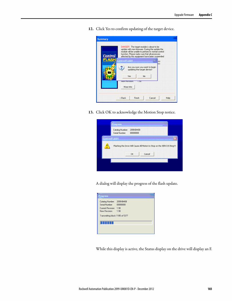
Upgrade Firmware Appendix C
12. Click Yes to confirm updating of the target device.
13. Click OK to acknowledge the Motion Stop notice.
A dialog will display the progress of the flash update.
While this display is active, the Status display on the drive will display an F.
Rockwell Automation Publication 2099-UM001D-EN-P - December 2012 183

Appendix C Upgrade Firmware
The Update Status dialog indicates success or failure as described below.
14. Click OK.
The ControlFlash software returns to the Welcome screen where you can flash another drive or select Cancel to exit the program.
Flashing If
Succeeded 5. Update complete appears in a GREEN status dialog.6. Go to Step 2.
Failed 1. Update failure appears in a RED status dialog.2. Contact Technical Support.
184 Rockwell Automation Publication 2099-UM001D-EN-P - December 2012

Index
Numerics1756 module properties 1121756-MxxSE interface module 1102090-K6CK-D15F 982090-K6CK-D15M 982090-K6CK-D26M 982090-K7CK-KENDAT 48, 98, 99
AAC line filters
noise reduction 36accessories 10applying power 126auxiliary feedback
pin-outs 49specifications 66
axis unstable 144
Bbandwidth 132base node address 106
example with two ControlLogix chassis 108, 109
baud rate,communication rate 106block diagrams
safe-off feature 178bonding
EMI (ElectroMagnetic Interference) 28high frequency energy 30mounting 28subpanels 30
buildmotor cables 72
bus regulator 125bus status LED 143
Ccables
build motor cables 72categories 35fiber optic 101maximum fdbk cable length 153maximum length of fiber-optic 101
catalog numberintegrated axis module 18
CB1, CB2, CB3 126CE
meeting requirements 20certifications
Rockwell Automation Product Certification 10changing parameters
HIM 135circuit breaker specifications
Kinetix 7000 151
circuit breakers 126sizing 23
configuringbase node address 106baud rate, IAM 106delay times 122IAM 106optical power level 107SERCOS module 110
connectingexternal shunt resistor 101feedback 93I/O 93input power 88motor brake 92motor power 92premolded feedback cables 95, 96SERCOS cables 101
connecting your Kinetix 7000 71contactor specifications
Kinetix 7000 152controller properties 110conventions used in this manual 9
Ddata rate 113date and time tab 111DC common bus
total bus capacitance 17typical installation 16
delay times 122digital inputs 54dip switches 113disable drive 146download program 125drive status indicators 128drive status LED 143drive tab 123
EEMC
motor ground termination 82EMI (ElectroMagnetic Interference)
bonding 28enable time synchronization 111enclosure
requirements 22enclosure sizing
Kinetix 7000 152environmental specifications
Kinetix 7000 154erratic operation 146error codes 138establishing communications 143external shunt resistor
wiring 101
Rockwell Automation Publication 2099-UM001D-EN-P - December 2012 185
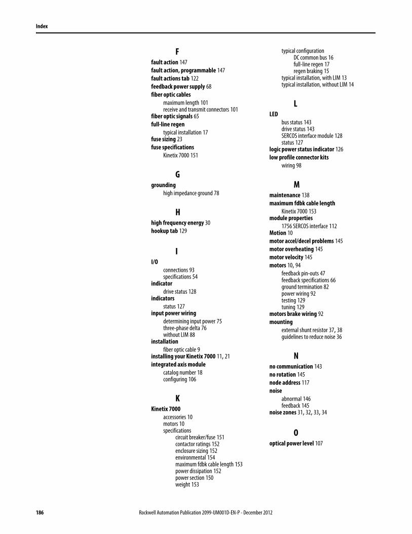
Index
Ffault action 147fault action, programmable 147fault actions tab 122feedback power supply 68fiber optic cables
maximum length 101receive and transmit connectors 101
fiber optic signals 65full-line regen
typical installation 17fuse sizing 23fuse specifications
Kinetix 7000 151
Ggrounding
high impedance ground 78
Hhigh frequency energy 30hookup tab 129
II/O
connections 93specifications 54
indicatordrive status 128
indicatorsstatus 127
input power wiringdetermining input power 75three-phase delta 76without LIM 88
installationfiber optic cable 9
installing your Kinetix 7000 11, 21integrated axis module
catalog number 18configuring 106
KKinetix 7000
accessories 10motors 10specifications
circuit breaker/fuse 151contactor ratings 152enclosure sizing 152environmental 154maximum fdbk cable length 153power dissipation 152power section 150weight 153
typical configurationDC common bus 16full-line regen 17regen braking 15
typical installation, with LIM 13typical installation, without LIM 14
LLED
bus status 143drive status 143SERCOS interface module 128status 127
logic power status indicator 126low profile connector kits
wiring 98
Mmaintenance 138maximum fdbk cable length
Kinetix 7000 153module properties
1756 SERCOS interface 112Motion 10motor accel/decel problems 145motor overheating 145motor velocity 145motors 10, 94
feedback pin-outs 47feedback specifications 66ground termination 82power wiring 92testing 129tuning 129
motors brake wiring 92mounting
external shunt resistor 37, 38guidelines to reduce noise 36
Nno communication 143no rotation 145node address 117noise
abnormal 146feedback 145
noise zones 31, 32, 33, 34
Ooptical power level 107
186 Rockwell Automation Publication 2099-UM001D-EN-P - December 2012
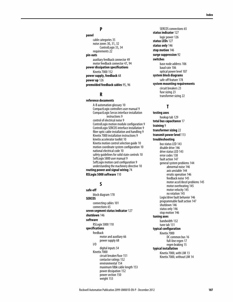
Index
Ppanel
cable categories 35noise zones 30, 31, 32
ControlLogix 33, 34requirements 22
pin-outsauxiliary feedback connector 49motor feedback connector 47, 94
power dissipation specificationsKinetix 7000 152
power supply, feedback 68power up 126premolded feedback cables 95, 96
Rreference documents
A-B automation glossary 10CompactLogix controllers user manual 9CompactLogix Sercos interface installation
instructions 9control of electrical noise 9ControlLogix motion module configuration 9ControlLogix SERCOS interface installation 9fiber optic cable installation and handling 9Kinetix 7000 installation instructions 9kinetix accelerator toolkit 10Kinetix motion control selection guide 10motion coordinate system configuration 10national electrical code 10safety guidelines for solid state controls 10SoftLogix 5800 user manual 9SoftLogix motion card configuration 9understanding the machinery directive 10
routing power and signal wiring 74RSLogix 5000 software 110
Ssafe-off
block diagram 178SERCOS
connecting cables 101connections 65
seven segment status indicator 127shutdown 146software
RSLogix 5000 110specifications
feedbackmotor and auxiliary 66power supply 68
I/Odigital inputs 54
Kinetix 7000circuit breaker/fuse 151contactor ratings 152environmental 154maximum fdbk cable length 153power dissipation 152power section 150weight 153
SERCOS connections 65status indicator 127
logic power 126status LEDs 127status only 146stop motion 146surge suppression 92switches
base node address 106baud rate 106optical power level 107
system block diagramssafe-off feature 178
system mounting requirementscircuit breakers 23fuse sizing 23transformer sizing 22
Ttesting axes
hookup tab 129total bus capacitance 17training 9transformer sizing 22transmit power level 113troubleshooting
bus status LED 143disable drive 146drive status LED 143error codes 138fault action 147general system problems 144
abnormal noise 146axis unstable 144erratic operation 146feedback noise 145motor accel/decel problems 145motor overheating 145motor velocity 145no rotation 145
Logix/drive fault behavior 146programmable fault action 147shutdown 146status only 146stop motion 146
tuning axesbandwidth 132tune tab 131
typical configurationKinetix 7000
DC common bus 16full-line regen 17regen braking 15
typical installationKinetix 7000, with LIM 13Kinetix 7000, without LIM 14
Rockwell Automation Publication 2099-UM001D-EN-P - December 2012 187

Index
Wweight specifications
Kinetix 7000 153who should use this manual 9wiring
build motor cables 72common dc bus power 78external shunt resistor 101ground reference 77grounding 81I/O connections 93impedance grounded power system 78input power
determining type 75without LIM 88
low profile connectors 98motor brake 92motor power 92requirements 71routing power and signal wiring 74SERCOS fiber optic cables 101unbalanced power system 78ungrounded power system 78
188 Rockwell Automation Publication 2099-UM001D-EN-P - December 2012

Publication 2099-UM001D-EN-P - December 2012Supersedes Publication 2099-UM001C-EN-P - February 2010 Copyright © 2012 Rockwell Automation, Inc. All rights reserved. Printed in the U.S.A.
Rockwell Automation Support
Rockwell Automation provides technical information on the Web to assist you in using its products. At http://www.rockwellautomation.com/support, you can find technical manuals, technical and application notes, sample code and links to software service packs, and a MySupport feature that you can customize to make the best use of these tools. You can also visit our Knowledgebase at http://www.rockwellautomation.com/knowledgebase for FAQs, technical information, support chat and forums, software updates, and to sign up for product notification updates.
For an additional level of technical phone support for installation, configuration, and troubleshooting, we offer TechConnectSM support programs. For more information, contact your local distributor or Rockwell Automation representative, or visit http://www.rockwellautomation.com/support/.
Installation Assistance
If you experience a problem within the first 24 hours of installation, review the information that is contained in this manual. You can contact Customer Support for initial help in getting your product up and running.
New Product Satisfaction Return
Rockwell Automation tests all of its products to ensure that they are fully operational when shipped from the manufacturing facility. However, if your product is not functioning and needs to be returned, follow these procedures.
Documentation Feedback
Your comments will help us serve your documentation needs better. If you have any suggestions on how to improve this document, complete this form, publication RA-DU002, available at http://www.rockwellautomation.com/literature/.
United States or Canada 1.440.646.3434
Outside United States or Canada Use the Worldwide Locator at http://www.rockwellautomation.com/support/americas/phone_en.html, or contact your local Rockwell Automation representative.
United States Contact your distributor. You must provide a Customer Support case number (call the phone number above to obtain one) to your distributor to complete the return process.
Outside United States Please contact your local Rockwell Automation representative for the return procedure.