IRIS Repair coding: Basic Principles

IRIS Basic Introduction & CourseIRIS Basic Introduction & Course
Basics of IRIS Coding (1)
IRIS coding has in most cases two, quite distinct, areas:
SYMPTOM AREAThe SYMPTOM area is intended to describe the set’s malfunction, AS PERCEIVED BY THE USER or any other casual observer.
It requires no specific technician know-how to be filled out, and it uses the
•Condition code •Symptom Code
DIAGNOSIS AREAThe DIAGNOSIS area is intended FOR THE TECHNICIAN, to describe where the defect was located, and the actions that were taken by him to repair the set.
It uses the•Section- & (optionally) PCB Code •Part Reference(s)•Defect Code(s)•Repair Code(s)•Repair Flag

SYMPTOM AREA• Condition code • Symptom Code
DIAGNOSIS AREA• Defect Code(s)• Repair Code(s)
NTF SYMPTOM AREAThe NTF Symptom is
intended for cases when No Technical Fault was found , to describe the reason why the owner / user of the set considered the set faulty .
It uses the• Non-Technical Fault code • Inserted into the SECTION
CODE area of Diagnosis area
Basics of IRIS Coding (2)
In some cases , when no technical fault was found on a set , IRIS coding has 3 , quite distinct, areas:
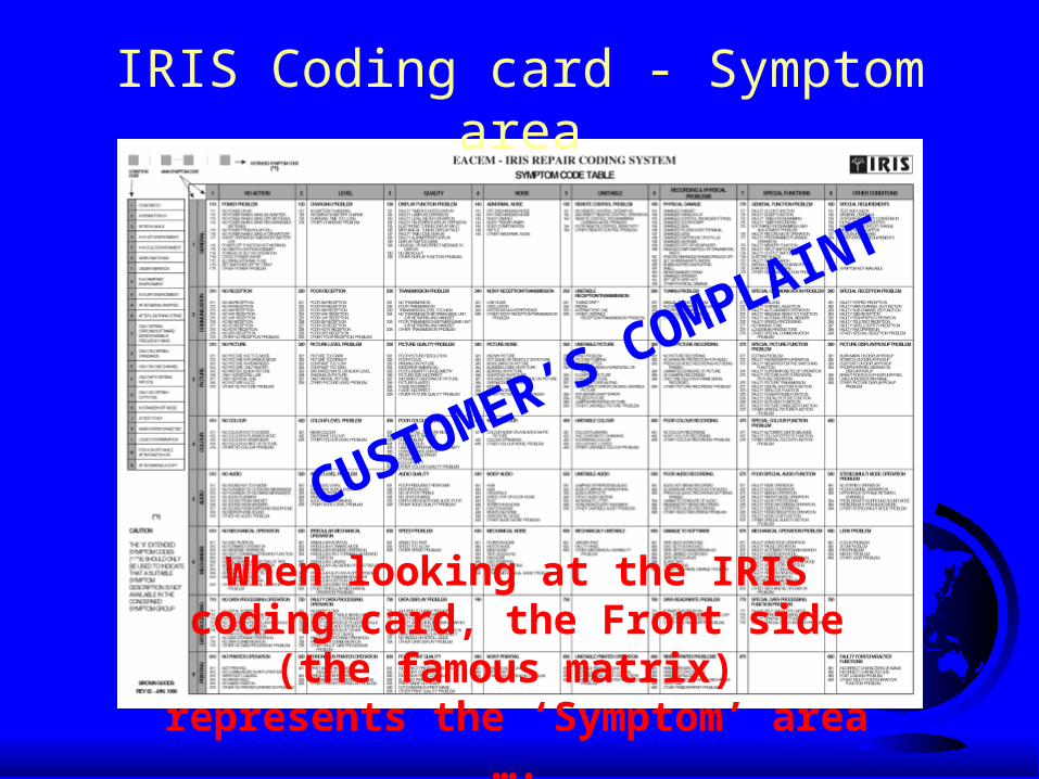
IRIS Coding card - Symptom area
When looking at the IRIS coding card, the Front side (the famous matrix) represents the ‘Symptom’ area ….
CUSTOMER’S COMPLAINT

IRIS Coding card - Diagnosis area
…whereas the Back side, (with the Section-, Repair- and Defect codes, represents the ‘Diagnosis’ area
TECHNICIAN’S DIAGNOSIS

IRIS Coding Card , NTF area
CUSTOMER’S PERCEPTION (OR
TECHNICIAN’S CONCLUSION )
And finally , in cases of Non-Technical Fault , similar to the Symptom Matrix , a NTF matrix
page has been added

The Symptom Code Logic

IRIS Coding card - Symptom area
The Symptom code should describe the problem as it can be perceived by any
of the five senses, based on simple questions which the enduser can
answer, like:• What exactly did (or did you not)
see, hear, feel, smell, taste,….?• Does this phenomenon occur all the
time, or under certain conditions?
Nobody should expect a technical analysis from a customer, so it is important to define only symptoms that anybody can perceive and
describe.

Get the Symptom from the Source!
The customer’s symptom description is the key for both the Dealer and Servicer to handle the repair promptly and efficiently
Therefore, it is most important to get this description directly from him (the source), and bring it along to the next step (the Repairer).
Therefore, whoever receives a repair from a customer should be familiar with IRIS symptom coding and use it.
(cartoon relay run)

Symptom coding by the Technician ?
By lack of symptom from Customer- or Reception-side, it is often necessary that the technician has to verify the symptom (by testing the set’s proper operation at the work bench), and then enters the Symptom code himself. But in such a case he/she also should take the same point of view of a customer : WHAT DO I SEE , HEAR , FEEL , SMELL ,...
He should NOT try to make an ‘on-the-spot’ diagnosis !
When I pushed ‘save’, it suddenly
exploded !Looks
like a resource conflict on the SCSI bus
master !

Symptom code “correction” In some cases it can also be necessary that a technician will:
* “enhance” the original customer claim, e.g. by adding a condition code.
* or he may even have to “correct” it, if it was clearly a wrong one.But of course also in such case , the basic idea of symptom coding should remain intact.
Examples of good technician corrections:1. Customer claim: There’s no picture on my TV; this will be
coded at reception into 1310. Technician however finds that in fact the set does not switch on power at all. He consequently corrects to : No Power (code 1110), or better: No Power on AC (code 1111)
2. Customer claim: Hiss noise from my cassette; this will be coded at reception to 1542. Technician finds out this is correct but in fact only appears in one channel. He consequently corrects to: E542

Basic Symptom Matrix structure
1 NO ACTION 2 LEVEL 3 QUALITY 4 NOISE 5 UNSTABLE 6RECORDING &
PHYSICAL PROBLEMS
7SPECIAL
FUNCTIONS8
OTHER CONDITIONS
11 POWER 12 CHARGING 13 DISPLAY 14 ABNORMAL NOISE 15 REMOTE CONTROL 16PHYSICAL DAMAGE
17GENERAL FUNCTION
18SPECIAL
REQUIREMENTS
21 NO RECEPTION 22 POOR RECEPTION 23TRANSMISSION
PROBLEM24
NOISY RECEPTION/ TRANSMISSION
25UNSTABLE RECEPTION/
TRANSMISSION26 TUNING PROBLEM 27
SPECIAL COMMUNICATION
PROBLEM28
SPECIAL RECEPTION PROBLEM
31 NO PICTURE 32PICTURE LEVEL
PROBLEM33
PICTURE QUALITY PROBLEM
34 PICTURE NOISE 35 UNSTABLE PICTURE 36POOR PICTURE
RECORDING37
SPECIAL PICTURE FUNCTION
38PICTURE
DISPLAY/PICKUP PROBLEM
41 NO COLOUR 42COLOUR LEVEL
PROBLEM43
POOR COLOUR QUALITY
44 NOISY COLOUR 45UNSTABLE COLOUR
46POOR COLOUR
RECORDING47
SPECIAL COLOUR FUNCTION
48
51 NO AUDIO 52AUDIO LEVEL
PROBLEM53 AUDIO QUALITY 54 NOISY AUDIO 55 UNSTABLE AUDIO 56
POOR AUDIO RECORDING
57POOR SPECIAL
AUDIO PROBLEM58
STEREO/ MULTIMODE OPERATION
61NO MECHANICAL
OPERATION62
IRREGULAR MECHANICAL OPERATION
63 SPEED PROBLEM 64MECHANICAL
NOISE65
MECHANICALLY UNSTABLE
66DAMAGE TO SOFTWARE
67MECHANICAL OPERATION PROBLEM
68 LENS PROBLEMS
71NO DATA
PROCESSING OPERATION
72FAULTY DATA PROCESSING OPERATION
73DATA DISPLAY
PROBLEM74
KEYBOARD / POINTING DEVICE
PROBLEM75
PERIPHERAL PROBLEM (NON-
STORAGE)76
DATA READ/ WRITE PROBLEM
77SPECIAL DATA PROCESSING
FUNCTION78
INTERFACE PROBLEM
81NO PRINTER /
SCANNER / COPIER OPERATION
82ERRONEOUS PRINT
/ SCAN / COPY OPERATION
83POOR PRINT
QUALITY84 NOISY PRINTING 85
UNSTABLE PRINTER OPERATION
86RIBBON/ PAPER
PROBLEM87 88
FAULTY FONT/ CHARACTER FUNCTIONS
Problem Type
Pro
blem
Area

Symptom Code structure1 2 3 4
Main Symptom
Specification
Con
ditio
n
Questions:Byte 1: Under which circumstances? (condition)Byte 2: Which main function group? (area of problem)Byte 3: Which type of malfunction? (type of problem)Byte 4: Which malfunction exactly?(problem specification)

The Diagnosis Code Logic

Diagnosis Area
By entering a suitable combination of different code types, a technician can give nearly full details concerning the performed repair.
For each aspect of repair , a specific code is available By combining the (user) symptom area and the
(technician) diagnosis area, a complete picture of the repair can be obtained, and a symptom/ cause analysis can be performed.

Section Identification
Consist of 3-byte Section codes Section codes indicate in which part of the set the
intervention(s) was (were) performed To make them easier to remember, the 3-byte codes form
so-called ‘mnemonics’ based on the english section names Section codes are easiest to understand when comparing
them to a set’s block diagram

Example of Section codes in a CD player
PROGRAMMING SECTION
PRG
REMOTECONTROLSECTION
REM
POW ERSUPPLY
PSU
SYSTEMCONTROLSECTION
SYS
SIGNALPROCESSING
DIGITALDPR
SERVOSECTION
SVO
AUDIOPROCESSING
A/DAPA/APD
INTERNALCONNECTOR
INC
CLOCK/TIMERSECTION
CLK
SIGNALOUTPUT
OUT
CONTROLPANEL
CTR
PROTECTIONCIRCUIT
PRT
SENSORUNITSNS
EXTERNALCONNECTOR(mains plug)
EXC
MEMORYCIRCUIT
MEM
EXTERNALCONNECTOR(e.g. Phono)
EXC
INFORMATIONDISPLAY
IDS88 : 88
MAINS LEADW IR
FLEXIBLE PCBFLX
Optical Pickup

Part Identification
Consists of Partnumber, Reference Number, and (optionally) Mounted Circuit Board code
These codes are manufacturer dependant.* Partnumber is the part order code(s) of replaced part(s)
* Ref. is the position reference of the part acted upon (replaced, adjusted, or else) as published in the service documentation. It is specially necessary if one partnumber is used on different positions.
* PCB is the name or code of the board on which the component is located
Lengths of these codes can vary , they should be aligned from left side

Defect Identification
“Defect Codes” specify the type of defect(s) that was (were) found by the technician.
Mechanical as well as Electrical codes are defined. They always refer immediately to the part identified on the
same line. However, some types of Defect codes can also be “self-
standing”, i.e. not related to a specific part. One of those “independent” Defect codes is “No Problem
Found”; reasons for this can be further specified.

Repair Identification
Repair Codes identify the actions performed by the technician
Most common types of repair, like replacement, cleaning, alignment etc. must be referenced to specific components.
Also here, a number of ‘self-standing’ Repair codes exist, e.g. software upgrading, return without repair, estimation of repair, upgrading, etc..

Parts Quantity
Quantity field will indicate how many of a particular part have been replaced.* Logically, a quantity of more than ‘1’ usually only refers to
‘common’ parts, which have no specific position code of their own (e.g. screws, washers,…)
* In case another action than replacement was taken, ‘quantity’ field must be ‘0’ (zero) or left blank.

Parts Flag
The “Flag” is an indication of the “most important” part* Usually, several different parts are replaced during one repair,
although mostly just one part is found to be the real cause of the symptom.
* In case different symptoms are available, one “most important” part should be flagged per symptom.

The Non Technical Fault codes

NTF repairs (Non Technical Fault)
The possibility exists that for a variety of reasons , the user thinks a set is at faulty , he/she brings it to a servicer , and it appears after checking that there is no real technical fault.
In these cases , it is useful to try and find out what the cause was for the user to consider his set faulty. For that reason , the NTF table was developed. After consultation with the user , it is possible to codify the cause of the problem , enter it into the system and use if for the same purposes and with same benefits as symptom codes.
The NTF code table is developed according to the same principles as the Symptom code table , as a matrix

NTF repairs (Non Technical Fault)
Problem Area
Pro
blem
Reaso
n

How to insert the NTF code into the IRIS String ?
* A normal symptom code is inserted (ex : no power : 111)
* When no problem is found , a correct defect code can be inserted (ex: Defect code 4, No problem found, customer misunderstanding)
* The repair code is also known as Y (return without repair)
* The NPF code , either after consultation with the user , or by the technician when he is certain , is then inserted into the Section Code Area (ex: NTF code 121 : No battery fitted)
* When processing the IRIS codes , the Defect code , and/or Repair code will indicate if the contents of the Section code is a real section , or an NTF code , there is no ambiguity.
NTF repairs (Non Technical Fault)

Some typical repair examples A Video recorder is brought in and customer claims “Set has no colour;
sometimes my tapes are damaged”; the receptionist codes these symptoms as respectively “1410” and “1660”
The technician’s actions:* When playing a test tape, he sees that the first symptom is indeed present.* He suspects IC101in the Colour processing circuit, and replaces it; this doesn’t seem to
solve the problem however.* After further troubleshooting, he finds a badly soldered resistor R123 in the same
circuit, which apparently by simple resoldering solves the problem.* Next he tackles the second symptom and checks the mechanism;
he sees that cassette unloading sometimes blocks, apparently due to a worn guide (ref. 513) in the threading mechanism.
* He replaces the guide in question, and also cleans the tape path. Testing reveals that also this problem is solved.

How this example is coded
1412 = (constantly) no colour in playback
2626 = (intermittently) irregular unloading of tape
CPA = colour processing, analog
A = replaced
D = resoldered
E = cleaned
THR = threading mechanism
TPT = tape path section
T = bad contact
A = worn out
the flags indicate the parts that were found to be the cause of each symptom
defect unknown
Note that first original symptom code was extended, and the second one corrected, by the technician!

No parts used
When no parts are used , some fields are even more important for analysis
Defect , Repair code as well as Section code should now give a good view on the problem and solution.
Suppose a cassette deck is damaging tapes , the customer claims this.
The technician finds the torque needs adjusting , and no parts need to be replaced.
Correct and complete encoding will now makeall the difference for later analysis.

Poor coding :
we can only know “some adjustment” took place
Better coding :
now we know exactly which adjustment was done
Alignment
Torque Potentiometer

In the above example , the reference to the microphone , along with the correct MIC section code give us the information which part was not correctly aligned.
Misaligned AlignmentReference of microphone

Symptom problem
Following is an example how NOT to use symptom coding.
Suppose the customer did not give a clear symptom , Or the person who was at the frontline did not take care
properly
The result can be rather bad.

Power problemMicrophone
Battery cover, screw , connector cover , case assy , antenna ring
Antenna
This symptom does NOT match any of the parts !!
Maybe it was entered as such at reception, but the technician should have corrected it

The same repair with corrected codes gives a lot more information !!