IPC-610-H 4U Rackmount Chassis User�s Manual
Copyright Advantech Co., Ltd copyrights this documentation and the software included with this product in 2002. All rights are reserved. Advantech Co., Ltd. reserves the right to make improvements in the products described in this manual at any time without notice. No part of this manual may be reproduced, copied, translated or transmitted in any form or by any means without the prior written permission of Advantech Co., Ltd. Information provided in this manual is intended to be accurate and reliable. However, Advantech Co., Ltd. assumes no responsibility for its use, or for any infringements of the rights of third parties, which may result from its use. Acknowledgments PC-LabCard is a trademark of Advantech Co., Ltd. IBM and PC are trademarks of International Business Machines Corporation. MS-DOS, Windows, Microsoft Visual C++ and Visual BASIC are trademarks of Microsoft Corporation. Intel and Pentium are trademarks of Intel Corporation. Delphi and C++ Builder are trademarks of Inprise Corporation. CE notification The IPC-610-H, developed by ADVANTECH CO., LTD., has passed the CE test for environmental specifications when shielded cables are used for external wiring. We recommend the use of shielded cables. This kind of cable is available from Advantech. Please contact your local supplier for ordering information.
IPC-610-H User’s Manual ii

On-line Technical Support For technical support and service, please visit our support website at: http://www.advantech.com/support Note: DDDDDDDDDDDDDDDDDDDDDDDDDDDDDDDDDDDDDDDDDDDDDDDDDDDDDDDDDDDDDDDDDDDDDDDDDDDDDDDDDDDDDDDDDDDDDDDDDDDDDDDDDDDDDDDDDDDDDDDDDDDDDDDDDDDDDDDDDDDDDDDDDDDDDDDDDDDDDDDDDDDD Part No. 2003178400 1st Edition
Printed in Taiwan July 2002
iii
Contents
CHAPTER 1 GENERAL INFORMATION...................................... 2 1.1 INTRODUCTION................................................................ 2 1.2 SPECIFICATIONS .............................................................. 2 1.3 PASSIVE BACKPLANE OPTIONS ....................................... 3 1.4 POWER SUPPLY OPTIONS................................................. 4
Tablel 1-1 Installation Flow Chart ..................... 4 1.5 SYSTEM REGULATION ..................................................... 5
Tablel 1-2 Installation Flow Chart ..................... 5 1.6 DIMENSIONS.................................................................... 5
Fig. 1-1 Installation Flow Chart ......................... 5 1.7 EXPLODED DIAGRAM ...................................................... 6
Fig. 1-2 Installation Flow Chart ......................... 6 CHAPTER 2 SYSTEM SETUP.......................................................... 8
2.1 SYSTEM INSTALL............................................................. 8 2.1.1 Attaching the handles.......................................... 8 2.1.2 Removing the top cover ...................................... 8
Figure 2-1........................................................... 8 2.1.3 Chassis Front and Rear Sections ......................... 9
Figure 2-2........................................................... 9 Figure 2-3......................................................... 10
2.1.4 Drive Bay Installation ....................................... 10 Figure 2-4......................................................... 11
2.2 IPC-610-H SERIES INSTALLATION ................................ 12 2.2.1 IPC-610BP-00XH ................................................ 12 2.2.2 IPC-610MB-00XH............................................... 12
2.3 LED INDICATORS.......................................................... 13 2.3.1 System Status LED .............................................. 13
Tablel 2-1 ......................................................... 13 2.3.2 Power Status LED................................................ 13
Table 2-2 .......................................................... 13 2.4 COOLING FAN AND FILTER............................................ 14
Figure 2-5......................................................... 14 Figure 2-6......................................................... 14 Figure 2-7......................................................... 15
IPC-610-H User’s Manual iv

2.5 INSTALLING CPU CARDS & ADD-ON CARDS ............... 15
APPENDIX A BACKPLANE........................................................... 18 Figure 1.1 ......................................................... 18 Table 1.1 Connectors........................................ 19 Table 1.2 Routing Table ................................... 20
v


General Information
CH
AP
TER
1
Chapter 1 General Information 1.1 Introduction
IPC-610-H is a 4U height 14-slot rackmount IPC chassis designed for building mission-critical applications. The unit includes a versatile 14-slot passive-backplane by option (which supports ATX M/B form factor), a high-efficiency 300W ATX with power factor correction (PFC) power supply, and dual easy maintenance cooling fan which provides abundant cooling. A wide range of standard computing peripherals can be integrated with the chassis to meet different application development under mission-critical environment 24 hours a day, 7days a week.
1.2 Specifications General
! Construction: Heavy duty steel chassis ! Drive bay: Shock-proof. Front accessed three 5.25" & one 3.5�
drivers ! Cooling system: Dual easy-to-replace 84 ~ 114 CFM cooling
fan with front-access air filter ! Controls: Power switch (on-off or momentary) and reset switch
behind the lockable door Indicators ! Power: Green LED shows the power status ! HDD: Green LED for HDD activity ! Voltages: 3.3V/+5V/+12V/-5V/-12V/Vsb single-color LED
(green) shows the voltage status ! Connectors: Front access USB and PS/2 keyboard, rear panel
9-pin connector (9-pin connector is not included for the M/B version)
! Paint Color: Pantone 414U Gray, textured ! Operating temperature: 0 ~ +40°C (32°F ~ 104°F)
IPC-610-H User's Manual 2

! Storage temperature: -40° to +60°C (-40° to +140°F) ! Relative Humidity: 10 ~ 95%@40°C, non-condensing ! Vibration: (Operating) 5Hz ~ 500Hz, 0.5G rams ! Shock (operating): 2.0 G with 11m Sec duration, 1/2 sine wave ! Acoustic Noise: Less than 52 dB sound pressure at +5° to
+28°C (+41° to +82°F) ! Altitude: 0 to 3048m (0 to 10,000 ft) ! Slide rails: General Device C-300 series supported ! Dimensions: 482(W) x 173(H) x 480(D)mm (19�x 6.8� x 18.9�) ! Weight: 16-18kg (35.2 � 39.6lb) ! Safety: CCC approved
1.3 Passive Backplane Options
Single System Backplane models (refer appendix for details) # PCA-6114P4-C
3

1.4 Power Supply Options
Specifications Model Name Watt Input Output Mini-load Safety MTBF
PS-300ATX-Z (ATX,PFC) 300 W
AC 90~135V AC 180~265V
(Full-range)
+5 V @ 30 A +3.3 V @ 24 A +12 V @ 15 A -12 V @ 0.8 A -5 V @ 0.3 A +5 Vsb @ 2 A
+5V @ 1A +12V @ 0.5A
UL/cUL/CSA, CE EN61000-3-2
Class D TUV, Nordic,
CB CCC
100,000 hours @ 25℃ 275W load
PS-400ATX-Z (ATX PFC) 400 W AC 90~264V
(Full-range)
+5V @ 42A +3.3V @ 20A +12V @ 14A -12V @ 1A -5V @ 1A
+5 Vsb @ 0.75 A
+5V @ 2.5A +12V @ 0.5A
UL/cUL/TUV/ CCC
100,000 hours @ 25℃ 75% load
PS-250ATX-Z (ATX,PFC) 250 W AC 95~132V
AC 190~264V
+5V @ 27A +3.3V @ 20A +12V @ 13A -12V @ 0.8A -5V @ 0.3A
+5 Vsb @ 2 A
+5V @ 0.5A +12V @ 0.3A
UL/cUL/CSA/TUV/CB/CCC 100,000 hours@25℃
+3.3V @ 0.3A
+3.3V @ 0.2A
Tablel 1-1 Installation Flow Chart
IPC-610-H User's Manual 4

1.5 System Regulation
Model Name With Power Supply With Backplane or MotherBoard Regulation
IPC-610P4-25ZH PS-250ATX-Z(ATX PFC) PCA-6114P4-C CCC
IPC-610BP-00XH w/o w/o None
IPC-610BP-25ZH PS-250ATX-Z(ATX,PFC) w/o CCC
IPC-610BP-30ZH PS-300ATX-Z(ATX PFC) w/o CCC
IPC-610MB-00XH w/o w/o None
IPC-610MB-25ZH PS-250ATX-Z(ATX,PFC) w/o None
IPC-610MB-30ZH PS-300ATX-Z(ATX PFC) w/o None
Tablel 1-2 Installation Flow Chart
1.6 Dimensions
Fig. 1-1 Installation Flow Chart
5
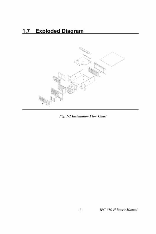
1.7 Exploded Diagram
Fig. 1-2 Installation Flow Chart
IPC-610-H User's Manual 6

System Setup
CH
AP
TER
2
Chapter 2 System Setup 2.1 System Install
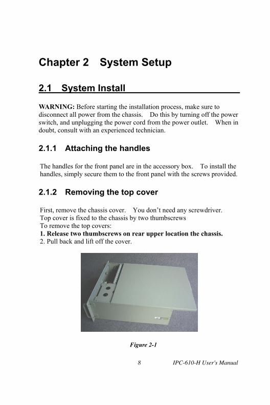
WARNING: Before starting the installation process, make sure to disconnect all power from the chassis. Do this by turning off the power switch, and unplugging the power cord from the power outlet. When in doubt, consult with an experienced technician.
2.1.1 Attaching the handles The handles for the front panel are in the accessory box. To install the handles, simply secure them to the front panel with the screws provided. 2.1.2 Removing the top cover First, remove the chassis cover. You don�t need any screwdriver. Top cover is fixed to the chassis by two thumbscrews To remove the top covers: 1. Release two thumbscrews on rear upper location the chassis. 2. Pull back and lift off the cover.
Figure 2-1 IPC-610-H User's Manual 8

2.1.3 Chassis Front and Rear Sections
The front panel switches which behind the door are used for system power switch and system reset. The door cover is on the right side of door cover, there are system LED status and key lock switch. The USB and P/S 2 keyboard connector are on the left side of front panel.
Figure 2-2
Power On/Off Switch
System Reset
Figure 2-3 System Reset : Press this switch to reinitialize the system. This is the same as the hardware reset button. Power On/Off Switch: Use this switch to turn on/off the system power. 9

Momentary Switch: Use this switch and by way of ATX (PS_ON) function to turn on system power. Please use system shutdown to turn off system power automatic or press momentary switch for a while to turn off system power USB connector: If you have any USB interface device want to connect with system, you could use this connector. PS/2 connector: If you want to connect PS/2 keyboard, you could use this connector. The rear section of B/P version includes B/P rear window. The rear 14-slot I/O brackets and the sheet metal kit for section of M/B version includes M/B rear window, 7-slot I/O brackets, ATX M/B I/O cover.
Figure 2-3
2.1.4 Drive Bay Installation The Standard Drive Bay of the IPC-610-H can hold 5.25� x 3 and 3.5� x 1 devices IPC-610-H User's Manual 10

Installation disk drives
1. Remove the top cover 2. Undo the four screws of cushion and four screws fixing the
Standard Drive Bay on right side 3. Lift off the Standard Drive Bay. See Figure 2-4 4. Insert the drives into their proper locations in the drive bay and
secure them with the screws provided. 5. Connect the disk drive power and signal cables.
Figure 2-4
11

2.2 IPC-610-H Series Installation
The IPC-610-H can be of two basic models, IPC-610BP-00XH and IPC-610MB-00XH.
2.2.1 IPC-610BP-00XH
IPC-610BP-00XH has no backplane, no power supply and has momentary switch on front panel. The momentary switch is suitable for ATX power supply such as PS-250ATX-Z, PS-300ATX-Z. For IPC-610BP-00XH, please plug 20-pin ATX power connector with backplane first, then use a orange-white wire (1700030500) to connector between CN# (PSON_GND_5VSB) of Backplane and �ATX feature connector� (CN20) of SBC, finally connect POWER SW wire with the �ATX soft power switch�(CN21) on SBC to finish the installation. 2.2.2 IPC-610MB-00XH ACP-610MB-00X is for M/B using, it is with ATX M/B rear I/O. ACP-610MB-00X is without M/B inside, has no power supply and has momentary switch on front panel. The momentary switch is suitable for ATX power supply such as PS-250ATX-Z, PS-300ATX-Z. For ACP-610MB-00X, please plug 20-pin ATX power connector with your ATX M/B, and then connect POWER SW wire with your ATX M/B to finish the installation. Please refer your ATX M/B installation guide for correct connection.
IPC-610-H User's Manual 12

2.3 LED Indicators
2.3.1 System Status LED
The System Status LED shows as following:
LED Description GREEN PWR System Power Normal HDD Hard Drive
activity Data access
Tablel 2-1
2.3.2 Power Status LED
The Power Status LED indicates the status of the backplane voltage signals.
LED Description Light No light +3.3V +3.3V signal Normal No output +5V + 5V signal Normal No output +12V +12V signal Normal No output -5V - 5V signal Normal No output -12V -12V signal Normal No output +5Vsb +5Vsb signal Normal No output
Table 2-2
When an LED fails to light, it indicates a problem with one of the voltage signals. Check to make sure that the power supply connector is properly attached to the backplane. If problem persists, consult an experienced technician.
13

2.4 Cooling Fan and Filter
There are two (2) Cooling Fans located inside the chassis. The Cooling Fans are easy maintenance and provide adequate cooling to the system by blowing air inward. Please refer the Figure 2-5 and Figure 2-6 to replace the defective fan. Press the location A and then pull the B which is showed on Figure 2-6 then the connector could be released. Please refer Figure 2-7 to change the filter if you found the filter was blocked with dust or other particles
Figure 2-5
A
B
Figure 2-6
IPC-610-H User's Manual 14

Figure 2-7
2.5 Installing CPU Cards & Add-On Cards
To install slot board computers and other add-on boards: Remove the chassis cover. Take out the hold down cramp Insert the CPU or add-on cards on suitable location Align and fix the screw to tighten the card to a fixed position Return the top cover after fix the hold down cramp
15


Backplane
AP
PE
ND
IX
A
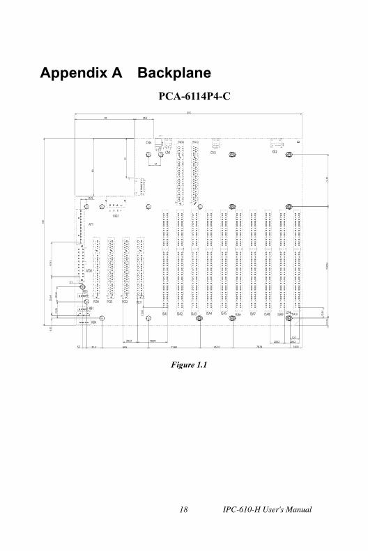
Appendix A Backplane PCA-6114P4-C
1
20.32
5.7 21.3 64.5
5.1
45.72
40.94
71.68 78.74
20.32
16.51
20.32
12.7
2.54
8.25
83
17
26.5
315
Figure 1.1
IPC-610-H User's Manual 18

1. Connectors Connector Description ISA1, 4~10 16 Bit ISA Bus connectorr PCI1~4 32 Bit PCI Bus connector ISA 2, 3 PICMG connector KB1 KB-In, from CPU card K/B connector KB2~KB3 KB-Out, 5 pin extemal K/B connector KB4 KB-Out, 6 pin PS/2 external K/ B connector BIG1 Big 4 Pin Power connectorr AT1 AT Power connector ATX1 ATX Power connector CN1 PS-ON Function, to CPU card for ATX power signal, 3 pin connector CN2 8 pin Alarm Board Power connectorr CN3 3 pin +5V and +12V Power connector
CN1 PIN Name 1 PS-ON 2 GND 3 5VSB
CN2 PIN Name 1 5VSB 2 GND 3 GND 4 -5V 5 +5V 6 +3.3V 7 -12V 8 +12V
CN3 PIN Name
1 +12V 2 GND 3 +5V
BIG1
PIN Name 1 +12V 2 GND 3 GND 4 +5V
AT1 PIN Name 1 NC 2 +5V 3 +12V 4 -12V 5 GND 6 GND 7 GND 8 GND 9 -5V 10 +5V 11 +5V 12 +5V
ATX1 PIN Name PIN Name 1 +3.3V 11 +3.3V 2 +3.3V 12 -12V 3 GND 13 GND 4 +5V 14 PS-ON 5 GND 15 GND 6 +5V 16 GND 7 GND 17 GND 8 NC 18 -5V 9 5VSB 19 +5V 10 +12V 20 +5V
KB1, 2, 3 PIN Name 1 KBCLK 2 KBDATA 3 NC 4 KBGND 5 KBVCC
Table 1.1 Connectors
19
IPC-610-H User's Manual 20
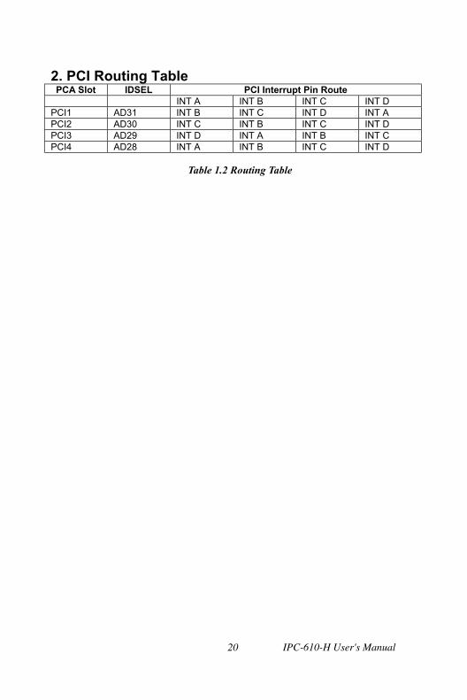
2. PCI Routing Table PCA Slot IDSEL PCI Interrupt Pin Route
INT A INT B INT C INT D PCI1 AD31 INT B INT C INT D INT A PCI2 AD30 INT C INT B INT C INT D PCI3 AD29 INT D INT A INT B INT C PCI4 AD28 INT A INT B INT C INT D
Table 1.2 Routing Table