Graduate Theses, Dissertations, and Problem Reports
2002
Investigation of frictional resistance on orthodontic brackets Investigation of frictional resistance on orthodontic brackets
when subjected to variable moments when subjected to variable moments
Edward Mah West Virginia University
Follow this and additional works at: https://researchrepository.wvu.edu/etd
Recommended Citation Recommended Citation Mah, Edward, "Investigation of frictional resistance on orthodontic brackets when subjected to variable moments" (2002). Graduate Theses, Dissertations, and Problem Reports. 1539. https://researchrepository.wvu.edu/etd/1539
This Thesis is protected by copyright and/or related rights. It has been brought to you by the The Research Repository @ WVU with permission from the rights-holder(s). You are free to use this Thesis in any way that is permitted by the copyright and related rights legislation that applies to your use. For other uses you must obtain permission from the rights-holder(s) directly, unless additional rights are indicated by a Creative Commons license in the record and/ or on the work itself. This Thesis has been accepted for inclusion in WVU Graduate Theses, Dissertations, and Problem Reports collection by an authorized administrator of The Research Repository @ WVU. For more information, please contact [email protected].
brought to you by COREView metadata, citation and similar papers at core.ac.uk
provided by The Research Repository @ WVU (West Virginia University)
INVESTIGATION OF FRICTIONAL RESISTANCE ON ORTHODONTIC BRACKETS WHEN SUBJECTED TO VARIABLE MOMENTS
Edward Mah, D.D.S.
Thesis submitted to the School of Dentistry
at West Virginia University in partial fulfillment of the requirements
for the degree of
Master of Science in
Orthodontics
Michael D. Bagby, D.D.S., Ph.D., Chair Peter W. Ngan, D.M.D.
Mark C. Durkee, D.D.S., Ph.D.
Department of Orthodontics
Morgantown, West Virginia 2002
Keywords: Friction, Orthodontics, Variable Moments
ABSTRACT
Investigation of Frictional Resistance on Orthodontic Brackets when Subjected to Variable Moments
Edward Mah, D.D.S.
Friction and binding occur in orthodontics during sliding mechanics. This paper evaluated the influence of a variable moment, simulating mastication, placed at the bracket-archwire interface to determine its effects on friction. Friction of self-ligating brackets were also compared to stainless steel and ceramic brackets. Six archwires were combined with four brackets. Friction (static, kinetic and dynamic) and load (dynamic and apparent stiffness) were measured. Dynamic friction was the frictional force that occurred when the applied force was variable (dynamic load). The results showed that static and kinetic friction were similar while dynamic friction was statistically greater. The Minitwin and Transcend 6000 brackets produced greater friction than the In-Ovation and Damon 2 brackets for all archwires, except with the 19x25TMA archwire. The Damon 2 bracket yielded the least friction. Dynamic friction was momentarily reduced below kinetic friction; thus, releasing the binding and enabling tooth movment.
iii
DEDICATIONS
To my parents, Bobby and Susanna Mah, for their enduring love and support. Thank you for allowing me to pursue my goals, to grow as an individual and teaching me to always strive to be the best.
To my grandmother, Kam Fung Loo, for all your love and guidance. I wish you were here to celebrate this accomplishment with me, even though I know you are in spirit.
To my sister and brother-in-law, Janette and Steven Hui, for their encouragement and support throughout the years. Janette your humor always brings me comfort. You have always been there for me. Thank you.
To my niece, Kaitlyn Chantal Hui, for bringing joy to my life. Your beautiful smile and radiant personality are priceless. You are so precious!
To my sister and brother-in-law, Dr. Mimi and Dr. Bryan Lo, for their support during my education. Thank you for your kindness, generosity and hospitality.
iv
ACKNOWLEDGEMENTS Dr. Peter Ngan, Chairman of Orthodontics, for his guidance, encouragement, friendship and sense of humor. Dr. Michael D. Bagby, Director of Biomaterials, for serving as chairman on my thesis committee and for his leadership, motivation and editing skills. Dr. Mark C. Durkee, Assistant Professor Department of Orthodontics, for serving on my thesis committee. Vince Kish, Senior Lab Instrumentation Specialist for Orthopedics, for designing and building the friction-testing machine. Dr. Gerry Hobbs, Associate Professor of Statistics, for his time and effort in performing the statistical analysis. Faculty, Department of Orthodontics, for sharing their knowledge and experience to further my orthodontic education. Donna, Marsha, Charlotte, Jackie and Debi for their assistance, support and friendship. Unitek, Ormco and GAC for their donation of products. Andrew Summers and Ryan Van Laecken, my classmates, for their kindness, friendship and humor. I could not have asked for two better classmates. Go Big Red!!! Rick, Brian, Cristiane, Anissa, Clemente and Brad, my fellow residents, for their friendship, humor and patience in answering my questions. Mike, Bryan, Nihar, Matt, Russ and Brett, my fellow residents, for creating and giving life to Mount Ed.
v
TABLE OF CONTENTS
ABSTRACT...............................................................................................................ii DEDICATIONS.........................................................................................................iii ACKNOWLEDGEMENTS.......................................................................................iv TABLE OF CONTENTS...........................................................................................v LIST OF FIGURES....................................................................................................viii LIST OF TABLES .....................................................................................................x Chapter 1 – Introduction Background ....................................................................................................1 Statement of the Problem...............................................................................2 Significance of the Problem...........................................................................2 Hypothesis......................................................................................................2 Definition of Terms........................................................................................2 Assumptions...................................................................................................4 Limitations .....................................................................................................4 Delimitations..................................................................................................5 Chapter 2 – Literature Review Friction...........................................................................................................6 Wire Size........................................................................................................9 Wire Shape.....................................................................................................9 Ligation ..........................................................................................................9 Bracket Width ................................................................................................11 Bracket-Archwire Angulation........................................................................11 Surface Roughness.........................................................................................12 Wire Material .................................................................................................13 Saliva..............................................................................................................14 Stainless Steel Brackets .................................................................................15 Ceramic Brackets ...........................................................................................15 Self-Ligating Brackets ...................................................................................17 SPEED Bracket ..............................................................................................19 In-Ovation Bracket.........................................................................................21 Damon SL Bracket.........................................................................................22 Damon System 2 Bracket...............................................................................23 Sliding Mechanics..........................................................................................24 Variable Moment ...........................................................................................28 Contact Angle ................................................................................................33 Chewing Cycle...............................................................................................34
vi
Chapter 3 – Materials and Methods Overview........................................................................................................37 Materials ........................................................................................................39 Test Bracket-Arylic Rod Assembly ...............................................................41 Pilot Study......................................................................................................42 Apparatus Setup .............................................................................................44 Test Bracket-Archwire Alignment.................................................................46 Load Cells and Computer Setup ....................................................................48 DC Power Supply...........................................................................................48 Bridge Amplifiers ..........................................................................................49 Test Trial Intervals .........................................................................................51 Data Collection and Evaluation .....................................................................51 Archwire Dimension(s) and Bracket Slot Measurements..............................53 Data Analysis .................................................................................................54 Statistics .........................................................................................................54 Wire Stiffness Chart.......................................................................................54 Contact Angle ................................................................................................55 Chapter 4 – Results Introduction....................................................................................................56 Friction Types ................................................................................................58 Archwires .......................................................................................................62 Brackets..........................................................................................................63 Bracket-Archwire Interactions .......................................................................64 Dynamic Load vs. Dynamic Friction .............................................................66 Bracket Slot Length .......................................................................................67 Arcwire Dimension........................................................................................68 Contact Angle ................................................................................................68 Apparent Stiffness..........................................................................................69 Miscellaneous Measurements Friction and Load Inherent in the Apparatus .....................................71 Chapter 5 – Discussion Introduction....................................................................................................72 Friction Types ................................................................................................72 Archwires .......................................................................................................74 Brackets..........................................................................................................76 Bracket-Archwire Interactions .......................................................................77 Dynamic Load vs. Dynamic Friction .............................................................79 Archwire Dimension......................................................................................80 Bracket Slot Length .......................................................................................80 Contact Angle ................................................................................................81 Apparent Stiffness..........................................................................................81 Miscellaneous Measurements Friction and Load Inherent in the Apparatus .....................................82 Clinical Implications ......................................................................................84
vii
Future Studies ................................................................................................86 Chapter 6 – Summary and Conclusions ................................................................87 Chapter 7 – Recommendations for Future Research ...........................................89 REFERENCES ..........................................................................................................90 VITA ..........................................................................................................................101
viii
LIST OF FIGURES Figure 1: Diagram of frictional forces ......................................................................6 Figure 2: Photograph of friction-testing apparatus ...................................................38 Figure 3: Photograph of Minitwin bracket................................................................39 Figure 4: Photograph of Transcend 6000 bracket .....................................................39 Figure 5: Photograph of In-Ovation bracket .............................................................40 Figure 6: Photograph of Damon 2 bracket................................................................40 Figure 7: Photograph of dental surveyor used to mount test brackets ......................41 Figure 8: Photograph of dental surveyor pin aligning test brackets
(close-up view).........................................................................................42 Figure 9: Photograph of friction-testing apparatus
(close-up view).........................................................................................45 Figure 10: Photograph of archwire alignment
(close-up view).........................................................................................47 Figure 11: Photograph of DC power supply and bridge amplifiers ..........................50 Figure 12: Sample graph of raw data ........................................................................53 Figure 13: Sample graph of raw data with labels......................................................56 Figure 14: Graph of static, kinetic and dynamic friction vs. brackets ......................59 Figure 15: Graph of Minitwin bracket friction .........................................................60 Figure 16: Graph of Transcend 6000 bracket friction...............................................60 Figure 17: Graph of In-Ovation bracket friction.......................................................61 Figure 18: Graph of Damon 2 bracket friction..........................................................61 Figure 19: Graph of static, kinetic and dynamic friction of the 4 brackets
averaged for each archwire ......................................................................62 Figure 20: Archwire groups ......................................................................................63
ix
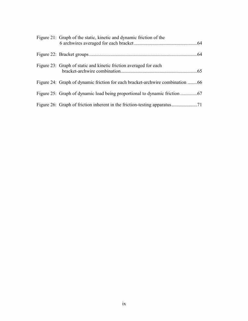
Figure 21: Graph of the static, kinetic and dynamic friction of the
6 archwires averaged for each bracket ....................................................64 Figure 22: Bracket groups.........................................................................................64 Figure 23: Graph of static and kinetic friction averaged for each
bracket-archwire combination...............................................................65 Figure 24: Graph of dynamic friction for each bracket-archwire combination ........66 Figure 25: Graph of dynamic load being proportional to dynamic friction ..............67 Figure 26: Graph of friction inherent in the friction-testing apparatus .....................71
x
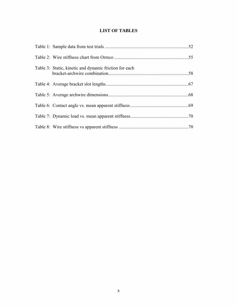
LIST OF TABLES Table 1: Sample data from test trials ........................................................................52 Table 2: Wire stiffness chart from Ormco ................................................................55 Table 3: Static, kinetic and dynamic friction for each
bracket-archwire combination.....................................................................58 Table 4: Average bracket slot lengths.......................................................................67 Table 5: Average archwire dimensions.....................................................................68 Table 6: Contact angle vs. mean apparent stiffness ..................................................69 Table 7: Dynamic load vs. mean apparent stiffness..................................................70 Table 8: Wire stiffness vs apparent stiffness ............................................................70
1
CHAPTER 1
INTRODUCTION
Background
Orthodontists are always seeking techniques in which to reduce friction during
sliding mechanics. Frictional resistance has been primarily studied in vitro. The majority
of investigators have attached a bracket to a mechanical testing machine that measures
frictional resistance. The bracket is ligated to and drawn along a suspended fixed
archwire sample. The mechanical testing machine records the amount of frictional
resistance that is present as the bracket slides along the archwire. However, this does not
fully emulate the clinical reality. When one chews, speaks, swallows, etc., at least
several thousand times each day, responsive minute movements of the teeth occur. In
addition, when the surrounding tissues, food particles, etc., contact the orthodontic
appliance, random asynchronous minute movements occur in the appliance. This results
in numerous minute momentary movements at the bracket-archwire interfaces. Previous
studies1 have demonstrated that vibrations at the bracket-archwire interface result in
frictional resistance approaching zero.
This study will investigate the frictional resistance of self-ligating, stainless steel
and ceramic brackets when variable moments are placed at the bracket-archwire
interface. The size and composition of archwires will be varied. The relative frictional
forces obtained in this study will be more meaningful when compared with each other, as
opposed to an actual force value that might be measured clinically on a patient.
2
Statement of the Problem
Do variable moments at the bracket-archwire interface influence friction? Do
self-ligating brackets exhibit less friction than stainless steel and ceramic brackets?
Significance of the Problem
Frictional resistance has always played a vital role in orthodontics. Its ability to
impair tooth movement results in the need for greater forces to move teeth, prolongs
treatment time and leads to loss of posterior anchorage. Therefore, sliding mechanics,
which is used in all facets of orthodontics, works best when friction is minimized. This
investigation will study self-ligating, stainless steel and ceramic brackets in the presence
of variable moments at the bracket-archwire interface to determine which yields the least
amount of friction.
Hypothesis
There is no difference in frictional resistance between self-ligating, stainless steel
and ceramic brackets when subjected to variable moments.
Definition of Terms
apparent stiffness � resistance to moments (stiffness) of an archwire measured when
rotating the bracket 20o.
coefficient of friction � the ratio of two forces; the weight (normal force) of an object
being moved along a surface and the frictional force that resists
movement. The coefficient is independent of the area of contact
and independent of the sliding velocity.1
3
conventional bracket � commonly used stainless steel or ceramic brackets that require the
use of a steel or elastic tie to enclose the archwire.
dynamic friction � frictional force that occurs when the applied (normal) force is variable
(dynamic load).
dynamic load � variable moment occurring with or without archwire pull.
friction � the force that retards or resists the relative motion of two objects in contact; the
direction is tangential to the common boundary of the two surfaces in contact.2
in vitro � outside the living body and in an artificial environment.
in vivo � within a living organism.
kinetic friction � the force that resists the sliding motion of one solid object over another
at a constant speed.3
mastication � biting and grinding food in your mouth so it becomes soft enough to
swallow; to grind and pulverize food inside the mouth, using the teeth and
jaws.
noise � electronic variability within the system.
oscillation � a single swing from one extreme limit to the other and back.
resistance � a force that opposes or slows down another force.
self-ligating bracket � a bracket that completely encloses the archwire without the need
for steel or elastic ties.
sliding � to move over a surface while maintaining smooth, continuous contact.
sliding mechanics � the process of an archwire moving through the slot of a bracket to
allow tooth movement.
4
static friction � the smallest force needed to start the motion of solid surfaces that were
previously at rest with respect to each other.3
stiffness � a combination of modulus of elasticity and moment of inertia
tipping � rotation about an axis perpendicular to the facial surface of a tooth
variable moment � tipping that is not constant (ie. sinusoidal or cyclical pattern)
Assumptions
1) Brackets, archwires and elastic ties of each type are identical in physical attributes
and composition.
2) Frictional force needs to be overcome in order to slide brackets along an archwire.
Limitations
1) Force of elastic ties holding the archwire in the bracket slot varies and decays with
time.
2) Application of this in vitro study to any in vivo situation has limitations.
With any testing situation, it is impossible to reproduce the exact situation one
might encounter in the mouth. In the oral environment, saliva amount and
content, bacteria type and concentration, types of liquids and solids ingested,
force of oral musculature upon chewing, and periodontal health are some of the
factors not encountered when performing this study in vitro.
3) Out of plane deformations were not evaluated.
5
Delimitations
1) Only maxillary first premolar orthodontic brackets with 0.022-inch vertical slot and
0.028-inch slot depth will be investigated.
2) Only 0.018-inch nickel titanium, 0.018-inch stainless steel, 0.019 x 0.025-inch TMA,
0.018 x 0.025-inch stainless steel, 0.019 x 0.025-inch stainless steel and 0.021 x
0.025-inch stainless steel will be evaluated.
3) Only injection molded O-ties (Ormco), which are more consistent in size and force,
will be used.
4) No 2nd or 3rd order bends will be examined.
5) Amount and frequency of variable moments placed at the bracket-archwire interface
will be 1.00 Hz (60 cycles/minute).
6) A final tipping angle of 20o of the bracket will be employed. The resulting force
varies with each bracket-archwire combination.
6
CHAPTER 2
LITERATURE REVIEW
Friction
Friction is the force that retards or resists the relative motion of two objects in
contact. Its direction is tangential to the common boundary of the two surfaces in
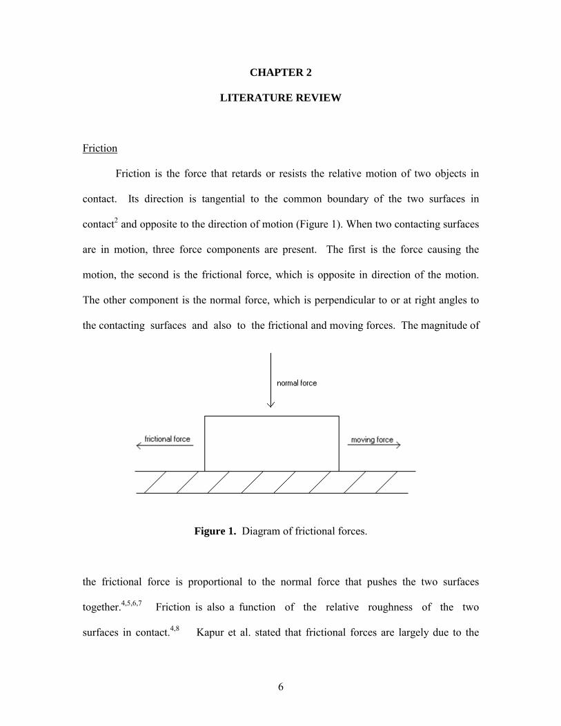
contact2 and opposite to the direction of motion (Figure 1). When two contacting surfaces
are in motion, three force components are present. The first is the force causing the
motion, the second is the frictional force, which is opposite in direction of the motion.
The other component is the normal force, which is perpendicular to or at right angles to
the contacting surfaces and also to the frictional and moving forces. The magnitude of
Figure 1. Diagram of frictional forces.
the frictional force is proportional to the normal force that pushes the two surfaces
together.4,5,6,7 Friction is also a function of the relative roughness of the two
surfaces in contact.4,8 Kapur et al. stated that frictional forces are largely due to the
7
atomic and molecular forces of attraction at the small contact areas between materials.
As a result, friction is greater between two surfaces of the same material than two
surfaces of different materials.9
Three general relationships of friction state the following:10,11,12
1) the frictional force is proportional to normal force when two materials are sliding
against each other. F = µN. Where F is the frictional force, µ is the coefficient of
friction and N is the normal force. This implies that the coefficient of friction is a
constant.
2) the frictional force is independent of the apparent area of contact; thus, large and
small objects have the same coefficients of friction.
3) the frictional force is independent of the sliding velocity of the objects in contact.
Two types of friction exist, static and dynamic. Each has a coefficient of friction
µs and µd. Static friction is the smallest force needed to start the motion of one solid
surface over another. Kinetic friction is the force needed to continue the sliding motion
of one solid object over another at a constant speed (i.e. the force that resists motion).1,13
The coefficient of friction for a given materials couple is a constant, which may
be dependent on the roughness, texture or hardness of the surfaces.14 The actual
frictional force is the product of the coefficient of friction and the normal force. In order
for one object to slide against the other, the force application must overcome the static
frictional force.15 The coefficient of static friction is always larger than kinetic friction.16
Several factors affect friction of orthodontic appliances. Mechanical variables
include:
8
1) bracket3,8,13,14,15,17-38: material, slot width and depth, bracket-archwire angulation
and surface roughness.
2) Archwire3,6,7,8,13,14,17-23,25,26,28,34,39-63: material, cross-sectional shape, size,
stiffness, surface coatings, surface roughness and bracket-archwire clearance.
3) method of ligation3,8,17,20,24,27,28,39,40,42,44,46,48,49,54,64-80: steel ligature ties,
elastomeric ties and force.
4) orthodontic appliance17,19,34,46,50: the number of brackets in series, inter-bracket
distance, level of bracket slots between adjacent teeth, forces applied for
retraction, sliding velocity and vibration.
Biological variables include: saliva,6,7,17,19,24,30,33,39,40,53,61,63,76,81,82 plaque,14
acquired pellicle, corrosion, temperature, mastication,1,8,14,83,84,85 bite force and tooth
mobility.86
Once bracket movement has been initiated, subsequent displacement of the
bracket relative to the wire requires smaller forces.17 Storey and Smith87 developed the
concept of optimal forces required for maximum rate of tooth movement with a range of
180 to 240 grams being recommended for permanent canine retraction.
Frictional resistance increases as the number of brackets included in the assembly
increases. The static friction recorded for single brackets generally doubled when two
premolar brackets were used, indicating a linear increase in frictional forces with number
of brackets.41 Leveling reduces the forces required for retraction of the teeth, because the
forces required for overcoming frictional resistance will be decreased.84
9
Wire Size
Most investigators agree that friction increases with increasing wire
dimension.6,8,14,17,19,20,21,22,39-47 This was confirmed by Frank and Nikolai,8 who also
concluded that increased wire stiffness increased friction. A bracket responds to the
sliding process with increased friction braking if the vertical dimension of the archwire is
increased only minimally or the archwire play in the bracket is
decreased.8,14,19,20,23,40,42,48,84 Sims et al.88 reported that resistance did not rise
exponentially with increasing archwire dimensions. However, Tidy18 found wire and slot
size had no effect on frictional force and that a reduction in wire size and subsequent
reduction in wire stiffness, permits greater tipping and hence an increase in binding.6,14
Wire Shape
Rectangular archwires generate greater friction than round wires due to the sides
and corners of rectangular wires binding the edges of the bracket slot.8,17,20,40,41,49,51,84,89
Sliding teeth along 0.018-inch round wire rather than rectangular wire is often suggested
since it is believed to generate less friction and conserve anchorage.39
Ligation
Elastomeric and stainless steel ligation methods of engaging the wire in the
bracket slot provide varying ligation force levels and may affect frictional
values.3,8,27,39,43,48,52,54 It has been postulated that the friction between conventional
brackets and stainless steel or elastic ligature ties impedes the clinical performance of the
new nickel titanium wires, and individual movements of teeth become nearly
10
impossible.65 Schumacher et al.66 stated that friction was determined mostly by the
nature of ligation and not by the dimensions of the different archwires. Friction is related
to the applied normal force, which is influenced by the degree of tension of the ligature
engaging the archwire into the slot24,67,68 and the coefficient of friction between the
ligature and the archwire material.8
Steel ligatures were found to induce less friction than elastic
ligature.8,23,40,41,52,66,69,70,71 Therefore, pre-expansion is recommended when elastics are
to be used.41 Bednar et al.52 reported that steel-tie ligated ceramic and steel brackets
brackets demonstrated less friction than the elastomeric-ligated ceramic and steel
brackets at every archwire size. Andreasen and Quevedo20 concluded that steel ligatures
can be very �clinician sensitive�, and that as the force of ligation increased, the frictional
resistance increased.8,17,24,28,67,72,84,88 However, Riley et al.40 determined that steel
ligatures generated more friction than elastic ligatures, particularly when plastic brackets
were used.
Investigations have also shown that elastomeric modules produce a wide variation
in force levels.22,73,74,75 Elastomeric ligatures have been shown to increase friction by 50-
175 grams,22 although this does not necessarily rise exponentially with increasing
archwire dimensions.48 The placing of �figure-eight� elastomeric ties was reported to
increase friction by a factor of 70-220% compared to conventional elastomeric ties.
Bracket designs that restricted the force of ligation from being placed on the archwire
generated lower kinetic frictional forces as compared with bracket designs that did not
restrict the ligation force.88
11
Permanent deformation of elastomerics, related to time (stress relaxation), how
fast they are stretched76 and deformation, as a result of hydrolysis due to water and moist
heat in the oral environment, were reported to change the degree of frictional
resistance.77,78,79 Therefore, static friction decays over time with elastomeric modules.41
The rapid rate of decay for these elastomeric ties and their predilection for harboring
large quantities of plaque and the resultant decalcification, suggests that there is little
merit in their use, especially in translatory movement and sliding mechanics.70
Bracket Width
Andreasen and Quevedo19 and Peterson et al.20 concluded that bracket width did
not affect friction, whereas Nicolls67 and Frank and Nikolai8 found that friction increased
with wider brackets. Larger frictional forces with wider brackets may be attributed to the
higher forces of ligation that result from the greater stretching of elastic ligatures on
wider brackets.17 However, Nicolls,67 Drescher et al.14,44 and Tidy18 found that as
bracket width increased, friction decreased due to the reduction in tipping, and hence
binding, by the wider bracket. This was confirmed by Garner et al.21 and Prososki et al..47
Bracket-Archwire Angulation
Greater angulation between the archwire and bracket yielded greater
friction.8,19,20,26,50,67,72,80,88 The dependence on angulation is more pronounced in stainless
steel than nickel titanium archwires, a possible reason being the lower stiffness of the
latter wire.13 Frank and Nikolai8 also found that frictional resistance increased in a non-
12
linear manner with increased bracket angulation. This is more correctly attributable to
binding rather than true friction.72
Surface Roughness
No definite relationship has been found between archwire and bracket surface
roughness and friction.47,80 The effects of roughness depend not only on the degree of
surface roughness but also on the geometry of roughness, orientation of roughness
features and relative hardness of the two contacting surfaces. Generally, friction tends to
be highest for very rough or very smooth surfaces. Very rough surfaces can cause high
friction because of the contact and interlocking of peaks and valleys.14 Very smooth
surfaces make possible relatively large areas of adhesion that tend to grow during sliding.
Surface films are powerful modifiers of friction, and they have been found to change
friction by as much as a factor of 10.29,31
Kusy and Whitley32 showed that, while the smoothest wire surface did have the
lowest coefficient of friction, surface roughness does not necessarily correlate with the
coefficient. Laser spectroscopy demonstrated that surface roughness values of various
orthodontic wires do not correlate with measured frictional values. A more recent study
using a profilometer showed no significant correlation between roughness and frictional
forces for various types of archwires.33
Other studies have demonstrated that friction increased with bracket slot surface
roughness.80 The significantly lower frictional resistance provided by stainless steel
brackets is most likely a result of their lower surface roughness, which is clearly visible
when comparing scanning electron micrographs.30
13
Wire Material
The material of the wire affects the frictional resistance produced.17,18,20,48
Consensus is still lacking pertaining to which wire material, stainless steel, nickel
titanium or beta-titanium, yields the most friction. Each of the three wire types have been
found to produce the least amount of friction, in at least one study, when compared to the
other two wires.
Investigations that pulled a straight piece of wire through orthodontic brackets
without any variable moment, found that nickel titanium produced the least amount of
friction, followed by stainless steel and then beta-titanium wires.3,18,14,15,20,33,34,46
However, there are studies that suggest significantly lower friction with stainless steel
wires than with nickel titanium or beta-titanium
wires.7,14,17,18,21,30,33,35,39,41,45,48,52,53,57,58,59,72,88 Other studies have found no significant
difference in the levels of friction between stainless steel and nickel titanium archwires
against stainless steel brackets.14,17,18,20,21,26,30,35,39,47,48,50
Beta-titanium was found to exert greater friction when compared to stainless steel
and nickel titanium13,14,17,21,33,35,45,47,53,60 possibly due to the adhesion of beta-titanium
archwire material to the brackets. Some investigators have stated that beta-titanium
archwires should be avoided whenever sliding mechanics is required. However, a study
conducted by Bazakidou et al.61 concluded that nickel titanium had more friction than
beta-titanium. With laser spectroscopy, stainless steel appeared the smoothest, followed
by beta-titanium and nickel titanium.33,47 Despite the fact that laser spectroscopy has
found the surface of beta-titanium to be smoother than nickel titanium,62 most studies
show that beta-titanium wires generate more friction than nickel titanium wires.14,17,35,39
14
Saliva The presence of saliva had an inconsistent effect on the static frictional resistance,
in some cases with saliva functioning as a lubricant and at other times acting to increase
friction.63 Investigators evaluating stainless steel brackets suggested that friction might
increase,7 decrease67 or not change19 when tested in saliva.
Stannard et al.7 reported that saliva increases frictional resistance rather than
acting as a lubricant, and this was also confirmed by other investigators.7,30,39,40,60,62,63
This finding contradicts the general perception of saliva as a lubricant for archwires and
brackets. Water and other polar liquids are known to increase adhesion or attraction
among polar materials and thus increase friction.7 Baker et al.6 showed a reduction in
friction between 15% to 19% under the presence of a saliva substitute (Xero-Lube). This
was confirmed by Kusy,32 Lorenz75 and Thurow.81
In the dry or wet states, the static and kinetic coefficients of friction were often
higher with ceramic than with stainless steel brackets.53 In another study, when ceramic
brackets were tested, artificial saliva increased the friction whereas human saliva caused
a decrease.30 The greatest difference between dry and wet states occurred with beta-
titanium archwires, in which the kinetic coefficients of friction in the wet state were
reduced to 50% of the values in the dry state.53
The explanation for the discrepancies in results may lie in the significance of the
loading forces used between the archwire and the brackets. At low loads saliva acts as a
lubricant, but at high loads saliva may increase friction if it is forced out from the
contacts between the brackets and the archwire. In the latter situation, saliva may
15
produce shear resistance to sliding forces.7,30 It was also stated that archwire alloy and
saliva seem to dictate frictional characteristics, which has been shown before.17,32,53
Stainless Steel Brackets
Stainless steel brackets exhibit lower frictional resistance than mono- or
polycrystalline ceramic brackets.30,35,60,80,82 Vaughan et al.,89 Kapila et al.17 and
Angolkar et al.39 demonstrated that sintered (metal injection molded, MIM) stainless steel
brackets generated 40 to 45% less friction than cast stainless steel brackets. Scanning
electron micrographs of sintered brackets demonstrated a smoother bracket surface due to
the sintering process. Sintering allows each individual bracket to be pre-molded in a
smooth streamlined manner. The stainless steel particles are then compressed into a
contoured, smooth, rounded shape as opposed to other procedures where the milling or
cutting process may leave sharp angular brackets that are more bulky and rough.89
Stainless steel wires created more friction with stainless steel brackets than with
ceramic brackets. This was confirmed by Kusy and Whitley35 and Spiller et al..50
Ceramic Brackets
Ceramic brackets were developed to improve esthetics during orthodontic
treatment. Those with a ceramic slot generated more friction than those with a stainless
steel slot6,30,36,53 and stainless steel brackets.15 This is most likely due to the increased
roughness and porosity of the ceramic surface30,39,52,53,55 and a sharp bracket slot edge3
thus, resulting in a higher coefficient of friction. Monocrystalline ceramic brackets have
smoother surfaces than those of polycrystalline, but the observed amount of friction
16
appears to be similar.45,62 Likewise, ceramic materials have a rougher and more porous
surface than stainless steel30,55 and may even abrade the archwire because ceramics are
harder than stainless steel.36 Scanning electron micrographs at 650x showed that the
polycrystalline structure of the ceramic bracket (Transcend 2000/3M Unitek) was
evident, varying from irregular to polyhedral in form with the surface also containing
many pores. The ceramic bracket with stainless steel slot showed the surface finish to be
smoother with fewer irregularities than the ceramic bracket slot.55 Therefore, greater
force is needed to move teeth when using ceramic brackets with no stainless steel slot.
Riley et al.43 stated that stainless steel ligating could compress the stainless steel
bracket slot and therefore increase friction. The binding between the ligatures and the
rough ceramic surface can also result in increased friction. Other investigators suggested
that the major cause of the increased resistance of ceramic brackets is due to the
difference in surface hardness between the ceramic material and stainless steel, beta-
titanium or nickel titanium wires.3,32,35,39,45,90,91,92 The Transcend 2000 bracket, cut with
diamond tools, has sharper and rougher sliding edges, and was found to scribe grooves
into the wires.3 Rounding the slot corners of ceramic brackets significantly reduced the
resistance of the brackets to archwire sliding.93
Some studies failed to detect any differences in frictional forces between ceramic
and stainless steel brackets.18,32 One study found that polycrystalline ceramic brackets
produced similar frictional forces to stainless steel brackets when using stainless steel or
nickel titanium wires. Therefore, there would be no disadvantage to using ceramic
brackets when teeth require sliding.55 However, some of those studies used models that
did not simulate the initial tipping and rotation movements that occur clinically. The
17
wires may not have contacted the bracket slot edges during the entire course of the
experiment; thereby, reducing the potential for detecting differences. DeFranco et al.34
confirmed this theory. At 0o angulation, with minimal potential for contact between
brackets and archwires, only minor differences in frictional forces were detected. With
increased angulations, however, which ensured bracket and archwire contact, friction was
significantly higher with the ceramic brackets.
Ceramic brackets are associated with several problems, such as fracture during
torsional and tipping movements,94-98 abrasion on opposing teeth,39,99,100 iatrogenic
enamel damage during debonding95,101,102,103 and increased frictional resistance in sliding
mechanics (polycrystalline or monocrystalline alumina), when compared with stainless
steel brackets.3,30,36,37,43,46,50,53,58,62,104,105 There have been several improvements in recent
years to reinforce ceramic brackets, such as precision-made stainless steel slot inserts.
Self-Ligating Brackets
Self-ligating brackets address two important concerns for orthodontists.
A decrease in frictional resistance, both static and dynamic, has to benefit the hard and
soft tissues, whereas a decrease in the time of archwire removal and insertion addresses
both ergonomic and economic considerations. The self-ligating bracket systems are also
advantageous in that they do not promote poor oral hygiene, as with elastomeric ties, and
eliminate any chance of soft tissue laceration to both the patient and the orthodontist from
the use of stainless steel-tie wires.70 The self-ligating bracket allows the clinician to
spend less time with the patient.
18
The concept of a ligatureless edgewise bracket first appeared in 1935 with the
Russell Lock appliance.59,106,107 The idea of a ligature-free system was further refined by
Wildman with his introduction of the Edgelok appliance in 1972. The mechanism for
retaining the archwire involved sliding a labially positioned cap across the top of the
archwire slot and into the locked position, thereby creating a rectangular slot, or tube,
within which the archwire had total freedom of movement. The Mobil-Lock bracket was
introduced in 1980. Hanson,108,109 also in 1980, created a spring-loaded, self-adjusting
ligatureless design that possessed the unique quality of retaining and actively influencing
control of the archwire within the archwire slot. This was called the SPEED appliance.
In 1986, the Activa bracket was designed and in 1994 the active Time bracket was
introduced. Damon in 1996 designed the passive self-ligating Damon SL bracket. When
the slide is closed, the lumen of the slot is full-size, which is critical for rotational control.
The passive Twinlock appliance, also designed by Wildman, was introduced in 1998.
Damon redesigned the Damon SL bracket and introduced the passive Damon System II
bracket in 2000. Voudouris also designed a new active self-ligating bracket named In-
Ovation in 2000.
All the inventors report a significant reduction in the level of friction, in addition
to shorter treatment time and chair-time, when compared with conventional bracket
systems.68,110,111 The fact that similar advantages were noted 47 years earlier with the use
of the first Edgewise self-ligating bracket, the Russell Lock,106 lends a certain degree of
credence to these current observations.
Sims et al.88 found that self-ligating brackets produced substantially less friction
than conventional elastomerically tied brackets, using archwires ranging from 0.016 x
19
0.022-inch to 0.019 x 0.025-inch.59,70,88,112,113 Ligating clips of the self-ligating brackets
possess a smaller magnitude of force pressing the archwire into the bracket slot relative to
the steel or elastomeric ligatures of the conventional systems.58 Therefore, less force is
required to produce tooth movement because they apply less friction to the archwire than
conventional tied Siamese brackets.88
Voudouris65 compared the friction produced by three types of conventional twin
brackets compared to three types of self-ligating brackets: one active (Sigma) and two
passive (Damon SL and Wildman TwinLock). When 0.019 x 0.025-inch stainless steel
wires were drawn through the brackets, friction values from highest to lowest were:
conventional twin brackets ligated with O-rings, brackets ligated with metal ligatures,
active self-ligating brackets and passive self-ligating brackets. Berger et al.23 found that
self-ligating brackets produced less friction than elastomeric or steel-tie ligated brackets.
SPEED Bracket
With the SPEED bracket, the inclined resilient spring clip forms the outer labial
wall.70,88 The aim of active ligation is to seat the archwire against the back of the bracket
slot for rotation and torque control. Some active clips are active only with larger
archwire sizes; in their passive state, the archwire freely moves within the lumen. The
smaller the lumen of the archwire slot, the greater the friction when using a light wire in a
distorted occlusion. Friction is also greater with sliding mechanics when a larger
working wire is used and the archwire is actively seated to the base of the slot, because
the flat surface of the rectangular wire contacts the flat surface of the slot base.65
20
Self-ligation contrasts the inflexible ligature tie wire or an elastomeric tie with a
degree of tension related to the decay rate of the polyurethane material. In comparison, a
steel ligature tie wire not only binds the archwire on both the mesial and distal aspects of
the bracket body but, should the cut end of the steel-tie wire be left in contact with the
archwire, then the degree of frictional contact is further enhanced. An elastomeric
ligature obviously also hugs the archwire on either side of the bracket�s archwire slot and
does not permit the degree of archwire freedom observed in self-ligating brackets.113
Berger et al.113 concluded that a lower level of applied force was required when
the SPEED bracket was used, regardless of which type of archwire was used. This was
true both at the time of the initial loading and again during continuous translation.
SPEED self-ligating bracket systems displayed a significantly lower level of frictional
resistance, dramatically less chair-time for archwire removal and insertion, and promoted
improved infection control, when compared with polyurethane elastomeric and stainless
steel tie wire ligation for ceramic and metal twin brackets.
Other investigations have also shown that SPEED brackets produce a reduction in
friction when compared to conventional brackets ligated with elastomeric or steel-
ties.41,113 When the SPEED bracket was compared to Minitwin brackets, the reduction in
friction was by 50-70%.88 Berger,113 in examining both static and kinetic friction, found
that SPEED brackets showed dramatically lower initial force levels, followed by an
almost constant low level of force during continuous translation as compared with other
orthodontic bracket-archwire systems, irrespective of the means of ligation. However,
another study found no differences in frictional resistance between the SPEED bracket
and a conventionally ligated twin bracket.70
21
The reduction in friction for SPEED brackets compared to conventional brackets
only occurred under certain conditions. SPEED brackets demonstrated low forces with
round wires, although with rectangular wires or in the presence of angulation, friction
was greatly increased.13,63 In other words, frictional forces increased in a stepwise
progression through the increasing wire sizes.113 This is probably due to the slot depth
and the active spring design. The effect of the flexible coverage depends on the presence
and absence of contact between the wire and spring, and thus is dependent on the surface
structure of the wire and the force delivered by the spring.13,88
Bednar et al.52 found the mean frictional values for self-ligating SPEED brackets
were similar or greater than elastomerically ligated stainless steel brackets. They felt that
despite the self-ligating clip design inherently decreasing friction, once the tooth tipped
during translation, it was the reduced width of the SPEED bracket that determined the
increased frictional resistance. The static and kinetic frictions for SPEED brackets were
similar. This indicates that once initial tooth movement occurs, a relatively large force is
still required to maintain tooth movement.41
In-Ovation Bracket
Fabricated by GAC, this bracket is very similar to the SPEED bracket, in that an
active clip is used. However, the In-Ovation bracket has tie-wings, which the SPEED
bracket does not; therefore, allowing elastomeric ties to be engaged.
22
Damon SL Bracket
Dr. Dwight Damon designed the Damon SL bracket to satisfy the following
criteria: Andrews straight wire appliance concept, twin configuration, slide forming a
complete tube, passive slide on outside face of bracket and brackets opening inferiorly in
both arches. He also concentrated on five other major areas: improving treatment quality
and control, dramatically increasing patient comfort, decreasing treatment time and
decreasing chair-time with longer appointment intervals. The goal of the Damon SL
system is to minimize friction at all stages of treatment. Configuring the slide as a
complete tube enhances torque control, reduces friction, and keeps a light initial wire
from �radiusing� from tie-wing slot to tie-wing slot in an extremely distorted occlusion.
Torque is always fully expressed in the Damon SL, since the continuous slot forms a
complete tube. The archwire must be completely engaged, or the slide will not close.65
The self-ligating Damon SL produces a reduction in friction. Teeth drift in the
path of least resistance. The brackets of the Damon SL system serve as mini-lip
bumpers, especially in the leveling phases. They are more effective in their sliding
mechanics than conventional brackets.114 The Damon SL bracket exhibits even less
friction than the SPEED bracket with respect to all wire types due to its passive
slide.13,88,113
The self-ligating Damon SL bracket demonstrated the lowest friction for all
dimensions of test wires when compared to A-company standard twin brackets, which
produced the highest friction with all wire dimensions tested.13,59,112 These results
corroborate the findings of previous studies of self-ligating brackets.58,70,113
23
The low friction related to the Damon SL bracket reflects the lack of normal force
in these brackets. This accounts for the negligible friction at zero degrees found in some
studies.113 These results indicate that self-ligating brackets require less force to produce
tooth movement than conventionally tied Siamese brackets.88
Difference in bracket friction may be due to design and manufacturing features.
The Damon SL has a locking spring-clip slide over the slot that holds the archwire
securely in place. Unlike the conventional elastomeric ligature, this slide allows the wire
to lie passively in the slot, reducing the normal component of force. Damon SL shows
smoother surface detail than the Minitwin. Although both brackets are manufactured
from 17-4 PH stainless steel, the Damon SL bracket is made by metal injection molding,
while the Minitwin is investment cast. Binding between the wire and bracket exist in the
Minitwin bracket, due to the sharper mesial and distal edges of the bracket slot. This
causes point contact between the wire and bracket and allows the wire to be held more
tightly in the slot by the elastomeric ligature.112
Damon System 2 Bracket
The new Damon 2 bracket has a 35% decrease in bracket width, a gate that is now
on the inside and a lower profile.115
The list price for the Minitwin, Transcend 6000, In-Ovation and Damon 2
brackets were $8.15, $16.50, $15.00 and $14.75, respectively. The Minitwin bracket was
about half the price of the other 3 brackets.
24
Sliding Mechanics
Sliding mechanics involves a relative displacement of wire through bracket slots
and whenever sliding occurs, frictional resistance is encountered. This technique is
commonly used in orthodontics in achieving closure of extraction sites, distalization of
teeth, eruption of high cuspids, rotations, leveling and changing arch forms. Frictional
forces developed between the bracket and archwire opposes such movements. The
consequent decrease in force available for tooth movement results in inhibition of tooth
movement,3 requirement for larger retraction forces and anchorage taxation. Up to 60%
of the applied force is dissipated as friction,116 which reduces the force available for tooth
movement.113 High levels of bracket-archwire friction may result in binding of the
bracket accompanied by little or no tooth movement.55 This higher frictional resistance
requires an increase in the magnitude of orthodontic forces needed to overcome the
friction, yet have enough residual force for optimal tooth movement. Therefore,
orthodontists are always seeking techniques to reduce or even eliminate friction.
In addition, as a result of appliance inefficiency and friction, it is difficult to
determine and control the magnitude of force that is being received by the individual
tooth.117 Quinn and Yoshikawa118 concluded that the rate of tooth movement increases
with increases in applied force up to a point, after which additional force produces no
appreciable increase in tooth movement. Schwartz,119 stated that a force as light as that
of capillary blood pressure (20-26 gm/cm2) would produce tooth movement.
Proffit26 proposed that the optimum force levels for orthodontic tooth movement
would be just high enough to stimulate cellular activity without completely occluding
blood vessels in the PDL. If a force is great enough to occlude the blood vessels and cut
25
off the blood supply, a hyalinized, avascular area is formed that must revascularize before
teeth can move. Pain is related to the development of ischemic areas in the PDL. Tuncay
suggested that oxygen is the trigger mechanism in the periodontium. According to
Proffit,26 if vascularity is critical to tooth movement, there is no doubt that light,
continuous forces produce the most efficient tooth movement and that heavy forces
should be avoided. Rygh recommended light, continuous forces for more effective tooth
movement in areas with cortical bone or bone with few marrow spaces. Warita63
compared the application of a light, continuous force (5 grams) versus a light, dissipating
force (10 grams) for 39 days on rat molars. He found 1.8 times greater tooth movement
with the light, continuous force.
Static friction is more important in tooth movement than kinetic friction. The
coefficient of static friction is always larger than kinetic friction. A high proportion of
the force used in tooth movement is lost due to static and sliding friction in the bracket-
archwire complex.69 The static and kinetic frictional forces generated between brackets
and archwires during sliding mechanics should be minimized to allow optimal tooth
movement.120 Drescher et al.14 reported that under low velocity conditions, both static
and kinetic friction occur.
Orthodontic forces are typically applied at a distance from the center of resistance
of the teeth.15 In the interaction between tipping and uprighting, rotation and derotation,
the bracket and thus the tooth �slides� into swinging movements, though constrained by
the friction, along the archwire. In these interactions, the extent of force loss due to
friction is proportional to the vertical and horizontal pressure of the archwire in the
bracket-archwire complex, which for its part depends on the amount of orthodontically
26
applied force.121 Translatory tooth movement along an archwire is not continuous, but
occurs as a series of small tipping and uprighting movements.
Average PDL space in human beings is about 0.2 mm, and teeth in function tend
to have a wider space, particularly in the cervical and apical portions. During periods of
orthodontic tooth movement, the distance between the root surface and the alveolar
socket may double or triple. Due to the width and compressibility of the PDL, the teeth
will therefore tip until contact is established between archwire and diagonally opposite
corners of the bracket wings, and rotate until contacts are established between the
archwire and ligature or labial bracket cover. These movements occur immediately on
force application and before sliding of the teeth along the archwire.15 The binding
between the bracket and archwire stops further crown movement until either wire
displacement, tooth mobility or subsequent remodeling releases the binding. Each time
the tooth moves a little, the static frictional resistance must be overcome, and kinetic
friction occurs.8 Provided the archwire does not deform, the teeth will maintain the
slightly tipped and rotated positions and slide parallel along the archwire.
Orthodontic mechanics attempts to move teeth efficiently; however, atraumatic
remodeling of periodontal tissues is rarely achieved. During tooth movement, the
remodeling periodontium exhibits changes in the gingiva, periodontal ligament and bone.
Oppenheim and Sandstedt122,123 hypothesized that the suffocation of the periodontal
ligament is the triggering mechanism behind the changes seen in bone; the undermining
and frontal resorption. Inhibition of synthesis of inflammatory mediators, with aspirin-
like drugs, resulted in significant (50%) reduction in tooth movement rate.124,125 The
inflammatory response requires significant vascular activity, as does remodeling. The
27
squeezed periodontal ligament space becomes devoid of oxygen, and this hypoxic
condition is abruptly reversed by the proliferating blood vessels that invade the injured
regions.126
Changes in blood supply can be observed in the human gingiva when subjected to
variable moments, either with tooth brushing127 or orthodontic tooth movement.128 It has
been suggested that the resistance of gingival tissues to remodeling is more important
than that of bone for tooth movement efficiency.129 Changes in vascular supply to all
three structures of the periodontium are the critical common triggers for remodeling.
The challenge for the orthodontist is to place enough pressure to stimulate cellular
activity without occluding the vascular supply in the periodontium.26 Beginning the
treatment with low force, low friction and small dimension wires will allow teeth to move
more individually, even though they are connected in a group.
It has been suggested that the resistance to tooth movement, in vivo, is not
governed by the classical laws of friction, but is a product of the binding and releasing
phenomenon at the bracket-archwire interface. This seems to suggest that bracket-
archwire sliding in vivo is much more dynamic than at first imagined. The effect that
mastication and tooth mobility has on this process is not fully understood and little is
known about the magnitude of tooth mobility that is required to release binding once it
has occurred.114
Hixon et al.130 reported that less force was needed intraorally than extraorally to
move the bracket-archwire test apparatus. He contributed this difference to oral forces,
especially from mastication, which produced other motions and permitted the wire to
slide through the tube more easily. This was confirmed by Jost-Brinkman and Meithke86
28
and Andreasen and Quevedo19 who recognized that relative movement within the
periodontium, enhanced by mastication, tended to decrease friction, and as the
periodontal ligament spaces enlarged during orthodontic movement, frictional resistance
is further reduced. Thurow81 suggested that relatively minute movements of teeth in
function provided a �walking� effect that allows a bracket to move along an archwire
more easily.
Variable Moment
Until Liew�s85 study in 1993, all frictional resistance measurements were
conducted in a steady state, absent any vibrations or disturbances at the bracket-archwire
interface that would be produced by various oral functions. He placed vertical
displacements on the archwire under differing loads using low frequency (91.3
cycles/minute) vibrations. He found that the resistance to archwire movement through an
orthodontic bracket was decreased by continuous repeated vertical displacement of the
wire. This reduction was as great as 85% for loads in the range 100-250 grams, while
loads as small as 25 grams reduced friction by more than 50%. Therefore, several
investigators have reported that forces required to overcome friction, clinically, are less
than those measured in steady-state laboratory experiments,80,131 due to mastication and
tooth mobility.
O�Reilly et al.1 studied 0.022 x 0.028-inch maxillary premolar stainless steel
brackets with 0o tip and 0o torque. Four different archwire types were investigated:
0.016-inch stainless steel, 0.019 x 0.025-inch beta-titanium, 0.019 x 0.025-inch stainless
steel and 0.021 x 0.025-inch stainless steel. An alignment fixture was used to ensure that
29
the bracket was placed at the center of each block and the bracket slot was at right angles
to the surface of each block.
The apparatus consisted of two parts: a lower member swivel mounting, which
supported the test bracket and an upper member slide that supported the fixed brackets
and the test archwire. The distance between the two brackets on either side of the
window measured 19.2 mm, which is the average distance between a lateral incisor
bracket and a second premolar bracket. The test bracket was then placed in the window
and the test wire was then placed through all four brackets in series.
A vibrating machine produced the bracket displacement. A frequency of 1.35 Hz
(81 cycles/minute) was used, which simulates normal chewing. The crosshead speed of
the archwire through the bracket slot was 1 mm/minute. An Instron universal testing
machine was used to measure the forces encountered during the study. Each test run
lasted one minute and the loads were recorded in newtons. Four amplitudes were chosen
for investigation ranging from 0 mm to 1.0 mm. A total of 16 cohorts (four wires and
four amplitudes) with 20 specimens in each group were assembled.
This study concluded that the effective sliding resistance between orthodontic
brackets and archwires is substantially reduced by repeated displacement. The reduction
in sliding resistance noted with displacement, depended on the archwire.
Braun et al.83 also performed an investigation involving deflection of the archwire
in bracket slots. Two types of 0.018-inch slot brackets, Ormco standard canine and
premolar brackets, were used. Three archwires were studied: 0.016-inch stainless steel,
0.016 x 0.016-inch stainless steel and 0.018 x 0.025-inch stainless steel. A bracket-
holding jig was fabricated to allow for changes in the bracket angle relative to the
30
archwire. The bracket angulations relative to the archwire were tested from 0o (as in
translatory movement) to a maximum of 25.5o, as in dental tipping.
The crosshead speed was 0.1 mm/minute and all tests were conducted in a dry
environment. Steel ties (0.010-inch) were used to hold the archwires in the bracket slots.
Deflections were applied to the bracket or archwire in random frequencies and in random
directions in all three planes of space. The deflections were applied with finger touch,
measured by a Correx gauge, to the bracket or archwire with a mean force of 87.2 grams
(range 20 to 200 grams).
This study concluded that frictional resistance momentarily became zero in 96%
of the experiments. This reduction seemed to be independent of the archwire size in the
0.018-inch slot brackets tested. The use of steel or elastomeric ties had no apparent
influence. Relative bracket-archwire angulations up to 25.5o, in the presence of
oscillations, did not increase frictional resistance.
Kapur et al.112 investigated frictional resistance on Damon SL and Minitwin
brackets without deflections in the archwire. All brackets were 0.0225 x 0.030-inch
maxillary first premolar brackets. The wires used were 0.018 x 0.025-inch nickel
titanium and 0.019 x 0.025-inch stainless steel. Each bracket was bonded perpendicular
to a cylindrical jig, which was then fixed in a specially designed apparatus. The
apparatus was secured to the base of an Instron universal testing machine. The wire was
attached to a tension load cell on the crosshead of the testing machine. Each test was
conducted for two minutes at a crosshead speed of 0.02 inch/minute. Frictional forces
were measured and analyzed using the Statistical Analysis System program. The results
31
revealed that the Damon SL bracket had lower kinetic frictional forces than the Minitwin
bracket with both wires.
Drescher et al.116 investigated changes in friction with respect to archwire
material, archwire size, bracket width and biologic resistance. A friction-testing
assembly simulating three-dimensional tooth rotations was constructed to study factors
affecting friction magnitude. Five wire alloys (standard stainless steel, Hi-T stainless
steel, elgiloy blue, nitinol and titanium molybdenum alloy) in five wire sizes (0.016,
0.016 x 0.022, 0.017 x 0.025, 0.018 and 0.018 x 0.025-inch) were examined with respect
to three bracket widths (2.2, 3.3 and 4.2 mm) at four levels of retarding force (0, 1, 2 and
3 Newtons). The results yielded the following factors to affect friction in decreasing
order: retarding force (biologic resistance), surface roughness of wire, wire size (vertical
dimension), bracket width and elastic properties of wire.
Omana�s3 study compared the frictional effects of seven brands of ceramic
brackets (Starfire, Contour Twin, Allure IV, Lumina, Illusion, CeramaFlex and
Transcend 2000) to those of a similar type of metal bracket (Mini Diamond). Each
bracket was tested on 0.018 x 0.025-inch straight pieces of nickel titanium and stainless
steel wires. Load ranging from 50-150 grams were randomly placed on a 10 mm long
counterweight arm to simulate the effects of varying amounts of bracket engagement
during tooth movement. As the wire was drawn through the bracket, the static frictional
forces were measured by an Instron machine.
The results showed that increasing levels of bracket engagement (load) resulted in
a corresponding increase in frictional force, there was no appreciable difference between
the frictional force values of the stainless steel and nickel titanium wires. In addition,
32
smoother, injection-molded ceramic brackets appear to create less friction than other
ceramic brackets, wider metal or ceramic brackets create less friction than narrower
brackets of the same material and excessive force is counterproductive because of
increased bracket friction and potential loss of posterior anchorage.
In vitro frictional resistance experiments that did incorporate variable moments at
the bracket-archwire interface concluded that the relationship between displacement and
friction appears to be linear. The effect of displacement was shown to have a significant
effect on sliding resistance regardless of wire type.
Earlier investigators suggest that increased relative bracket-archwire angulations
will produce greater vertical reactive forces at the interfaces and thus increased frictional
resistance.8,50,80 However, relative bracket-archwire angulations up to 25.5o, in the
presence of oscillations, did not increase frictional resistance. Although, it should be
noted that relative archwire stiffness, and consequently the related response to random
oscillations, is affected significantly by the archwire length defined by the location of the
end supports.83
If one considers the clinical situation, where there is intermittent movement
between the bracket and archwire, then clinically we may not be looking at true friction,
but rather a binding and releasing phenomenon. Kajdas et al.132 found that repeated
displacement of a bracket, equivalent to as little as 0.16 mm of mesio-distal crown
movement (which is within the range of normal tooth mobility), could reduce the sliding
resistance by as much as 85%. Assuming this fact, it is not unreasonable to conclude
that the reduced sliding resistance observed in vivo may be a result of this intermittent
movement between the bracket and archwire.
33
Braun et al.83 concluded that frictional resistance was effectively reduced to zero
each time minute relative movements occurred at the bracket-archwire interfaces.
Variable moments, although an inexact replication of those occurring in the oral
environment, resulted in frictional resistance to momentarily become zero. This
reduction seemed to be independent of the archwire size in the 0.018-inch slot brackets
tested. The use of steel or elastomeric ties had no apparent influence. Factors such as
the degree of dental tipping, relative archwire-slot clearances, and methods of tying, did
not have a measurable effect on frictional resistance in the simulated dynamics of the oral
environment. These findings contradict the studies performed in which no variable
moments were placed at the bracket-archwire interface.
Contact Angle
The angle needed before the archwire and bracket bind is called the contact angle.
Archwires with larger dimensions result in smaller contact angles than archwires with
smaller dimensions, when using the same bracket. Kusy133 created a formula that would
calculate the contact angle.
Contact Angle (θc) = 57.3 [1-(size/slot)] (2nd order angulation) (width/slot)
size = the archwire dimension that contacts the floor of the slot
slot = the bracket dimension at the floor of the slot
width = the mesial-distal dimension of the bracket
34
Chewing Cycle
Chewing is an alternating rhythm of isotonic and isometric contractions governed
by a central pattern generator in the brain stem.134 This rhythm is continually modified,
both voluntarily and in response to factors such as food hardness and bolus position.135,136
Cases with normal occlusion demonstrate no significant differences in masticatory
muscle activity between either the right and left or the working and nonworking sides.135
A more simple and regular pattern of chewing is seen, compared to cases with
malocclusion. The frequency of masticatory contact, which is only one causal
component of the minute relative motions at the bracket-archwire interface, has been
measured from 32 to 146 cycles per minute.26,137 The literature indicates that the enamel
contact time is about 0.22 seconds.138 Direct tooth contact during mastication only
occurs during the last half of the sequence of masticatory cycles.137
During chewing, intact teeth show considerable cuspal flexure, due to tooth
morphology and mandibular movement. Typically the buccal and lingual cusps flex in
the coronal plane because of the relatively large thickness of the buccal and lingual
enamel plates and the thinness of the enamel at the bottom of the central fossa.
Conversely, the incisor teeth flex in the antero-posterior plane, where the cross section is
thinnest. Of course, cuspal flexure is profoundly influenced by restorative procedures,
and control of cuspal flexure by material choice, cavity design and bonding
mechanisms.139
The elevator muscles consist of the anterior temporalis, posterior temporalis,
masseter and medial pterygoid muscles. The posterior temporalis muscle is responsible
for occlusion of the teeth, and individuals with large overbites have this muscle strongly
35
activated. The medial pterygoid muscle initiates the closing movement. Both the medial
pterygoid and masseter muscles direct and stabilize the mandible towards the side of the
bolus in the first part of the closing phase. The elevators produce the force necessary to
penetrate and crush the bolus.
The lateral pterygoid muscles move the condyle forward and contralaterally. The
depressor muscles consist of the digastric and mylohyoid muscles. The muscles
responsible for the opening movement during chewing are activated in the following
sequence: the mylohyoid, the digastric and the lateral pterygoid muscles.
Tooth contact is made simultaneously or shortly after maximal activity of the
anterior temporalis muscle. It is maintained for about 70 milliseconds after the activity
has ceased. Contact between the upper and lower teeth lasts 125 to 150 milliseconds in
each chewing stroke, or about 20% of its total duration. The period of tooth contact is
not a static situation. Molar contact, consisting of a large range of lateral and ventero-
dorsal positions, is made and broken before incisor contact, consisting of intercuspal and
slight lateral and protruded positions. Tooth contact is thus divided into 3 stages: first on
the molars, then in all areas and finally confined to the incisors.140
It has been shown that the bite force varies from one part of the oral cavity to
another. The greatest force is exerted in the region of the first molars and is less
anteriorly in the mouth. The force at the incisors is only about one-third to one-quarter of
that in the region of the molars. The bite force measured with the mandible in extreme
lateral positions, in protrusion and in retrusion is much lower than that measured in
intercuspal position. Individuals whose diet consists of hard foods have been found to
possess a stronger maximum bite force.141
36
An individual pattern exists with regards to mandibular movements in adults.
The masticatory movements in a given individual differ from each other.142 Men have a
stronger bite force and shorter chewing cycle with faster velocities than women.143 Bite
force is weakly correlated with general muscle force and skeletal dimensions. The forces
exerted during chewing are, as a rule, substantially lower than the seldom used maximal
bite force capacity. It has been found that kindergarten children have almost the same
amount of bite force as adults. Lindqvist and Ringqvist studied eleven-year old children
who grind their teeth resulting in atypical abrasion facets. They found that maximal bite
force was not significantly higher in children that brux than in controls without signs of
bruxism.141 Akinson and Shepherd observed a disturbed rhythm and an irregular pattern
of chewing in patients with TMJ dysfunction.142
37
CHAPTER 3
MATERIALS AND METHODS
Overview
This research study investigated the effects of variable moments on friction.
Different brackets and archwires were used in combination to evaluate the amount of
static, kinetic and dynamic friction present. Friction is the load necessary to pull the
archwire through a bracket. The load (force) required to tip the bracket to create a
constant bracket-archwire angulation was measured. Two types of load were evaluated:
dynamic and apparent stiffness. The testing apparatus consisted of a friction-testing
device, Instron universal testing instrument, two load cells, two signal amplifiers, two
computers and a rotating cam (Figure 2). The Instron machine engaged one end of the
vertically oriented archwire, which was inserted in the bracket slot, and it pulled the
archwire superiorly. Each bracket-archwire combination was tested 5 times, which
yielded friction and load data. During the 60 second trial, the archwire was pulled with
and without any variable moments. Variable moments were also measured with and
without archwire pull. The data was analyzed to determine which brackets and archwires
yielded the most static, kinetic and dynamic friction.
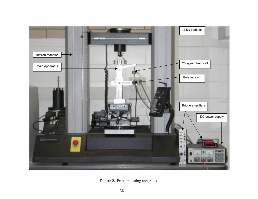
Figure 2. Friction-testing apparatus.
38
±1 kN load cell
250-gram load cell
Rotating cam
Bridge amplifiers
DC power supply
Instron machine
Main apparatus
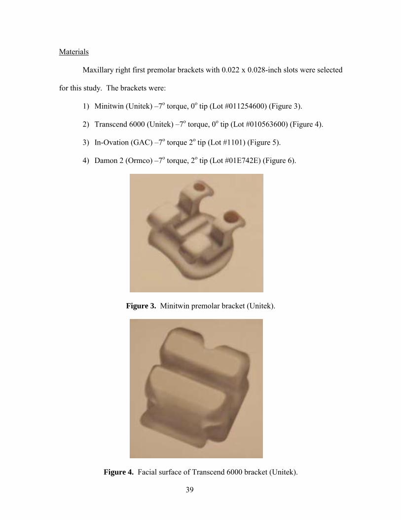
Materials
Maxillary right first premolar brackets with 0.022 x 0.028-inch slots were selected
for this study. The brackets were:
1) Minitwin (Unitek) �7o torque, 0o tip (Lot #011254600) (Figure 3).
2) Transcend 6000 (Unitek) �7o torque, 0o tip (Lot #010563600) (Figure 4).
3) In-Ovation (GAC) �7o torque 2o tip (Lot #1101) (Figure 5).
4) Damon 2 (Ormco) �7o torque, 2o tip (Lot #01E742E) (Figure 6).
Figure 3. Minitwin premolar bracket (Unitek).
Figure 4. Facial surface of Transcend 6000 bracket (Unitek).
39
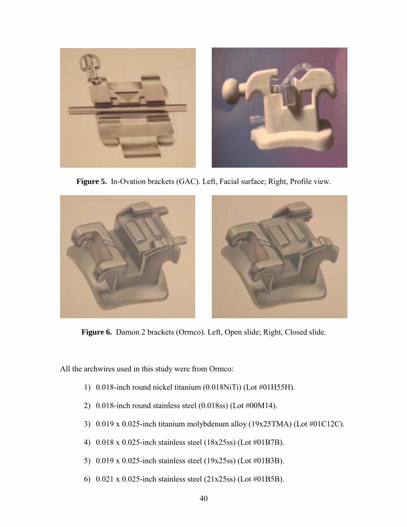
40
Figure 5. In-Ovation brackets (GAC). Left, Facial surface; Right, Profile view.
Figure 6. Damon 2 brackets (Ormco). Left, Open slide; Right, Closed slide.
All the archwires used in this study were from Ormco:
1) 0.018-inch round nickel titanium (0.018NiTi) (Lot #01H55H).
2) 0.018-inch round stainless steel (0.018ss) (Lot #00M14).
3) 0.019 x 0.025-inch titanium molybdenum alloy (19x25TMA) (Lot #01C12C).
4) 0.018 x 0.025-inch stainless steel (18x25ss) (Lot #01B7B).
5) 0.019 x 0.025-inch stainless steel (19x25ss) (Lot #01B3B).
6) 0.021 x 0.025-inch stainless steel (21x25ss) (Lot #01B5B).
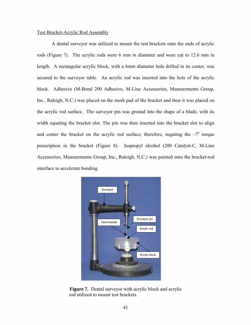
41
Test Bracket-Acrylic Rod Assembly
A dental surveyor was utilized to mount the test brackets onto the ends of acrylic
rods (Figure 7). The acrylic rods were 6 mm in diameter and were cut to 12.6 mm in
length. A rectangular acrylic block, with a 6mm diameter hole drilled in its center, was
secured to the surveyor table. An acrylic rod was inserted into the hole of the acrylic
block. Adhesive (M-Bond 200 Adhesive, M-Line Accessories, Measurements Group,
Inc., Raleigh, N.C.) was placed on the mesh pad of the bracket and then it was placed on
the acrylic rod surface. The surveyor pin was ground into the shape of a blade, with its
width equaling the bracket slot. The pin was then inserted into the bracket slot to align
and center the bracket on the acrylic rod surface; therefore, negating the �7o torque
prescription in the bracket (Figure 8). Isopropyl alcohol (200 Catalyst-C, M-Line
Accessories, Measurements Group, Inc., Raleigh, N.C.) was painted onto the bracket-rod
interface to accelerate bonding.
Surveyor
Surveyor pin Test bracket
Acrylic rod
Acrylic block
Figure 7. Dental surveyor with acrylic block and acrylic rod utilized to mount test brackets.
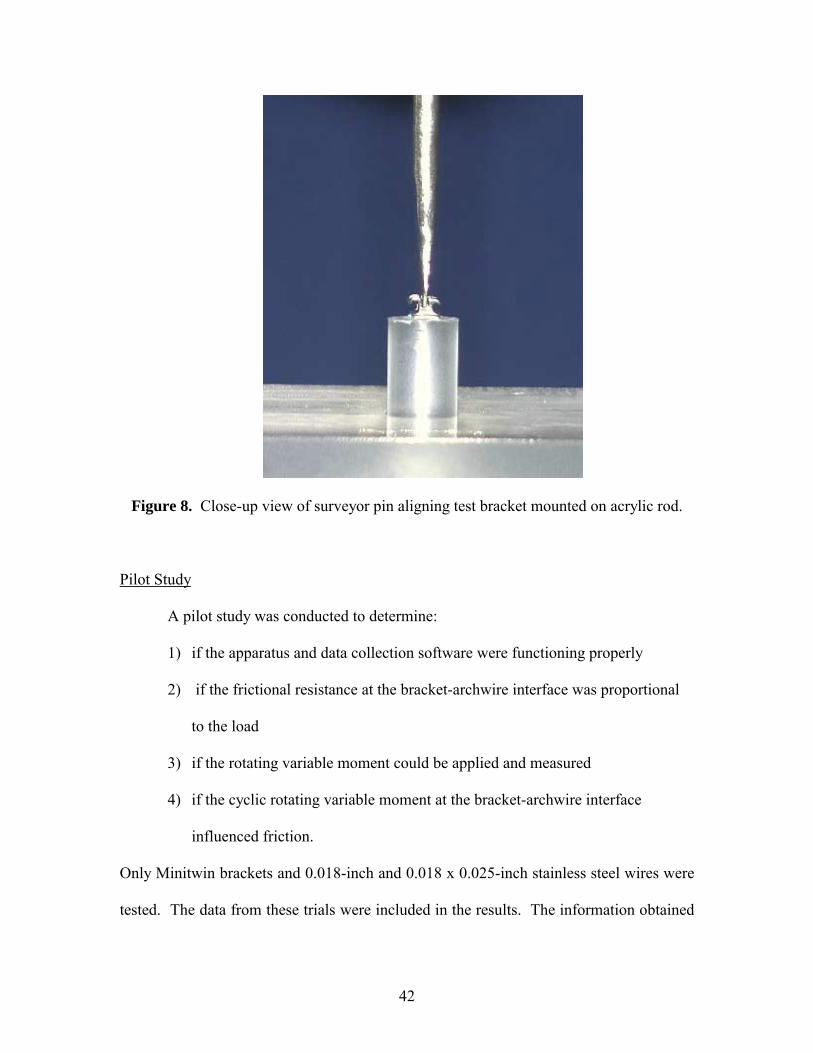
42
Figure 8. Close-up view of surveyor pin aligning test bracket mounted on acrylic rod.
Pilot Study
A pilot study was conducted to determine:
1) if the apparatus and data collection software were functioning properly
2) if the frictional resistance at the bracket-archwire interface was proportional
to the load
3) if the rotating variable moment could be applied and measured
4) if the cyclic rotating variable moment at the bracket-archwire interface
influenced friction.
Only Minitwin brackets and 0.018-inch and 0.018 x 0.025-inch stainless steel wires were
tested. The data from these trials were included in the results. The information obtained
43
from the pilot study enabled us to replicate results of previous research and to predict the
data obtained when the remaining brackets and archwires were studied.
After the pilot study was completed, the remaining brackets and archwires were
tested in the following order:
Order of brackets studied:
1) Minitwin
2) Transcend 6000
3) Damon 2
4) In-Ovation
Order of archwires studied:
1) 0.018-inch nickel titanium
2) 0.018-inch stainless steel
3) 0.018 x 0.025-inch stainless steel
4) 0.019 x 0.025-inch titanium molybdenum alloy
5) 0.019 x 0.025-inch stainless steel
6) 0.021 x 0.025-inch stainless steel
The Minitwin bracket was selected due to its popularity and the Transcend 6000
ceramic bracket for its alleged high friction. The Damon 2 and In-Ovation self-ligating
brackets were chosen due to their popularity, proposed reduced friction over conventional
brackets and their differing mechanisms of archwire engagement. The wires were chosen
due to their popularity and frequent use in sliding mechanics.
44
Apparatus Setup
A mounting plate was fabricated to aid in the alignment of archwires through test
bracket slots. The mounting plate was made of acrylic and had a hole drilled through its
center, with the diameter being larger than the acrylic rod on which the test bracket is
bonded (Figure 9). On either side, from the center of the hole, were Damon 2 maxillary
right first premolar brackets, 19.2 mm apart. This distance is the average space between
a maxillary canine and second premolar. All brackets were oriented in the same
direction, with the distogingival dot positioned superiorly and to the left. This means that
all bracket slots were vertically oriented. The mounting plate was secured with screws to
the superior end of two upright rectangular metal poles. The opposite end was attached
to a platform that rested on the Instron machine. The mounting plate was not changed
throughout the entire study, as this may have altered the findings or values due to the
possible differences in alignment of the Damon 2 brackets. The metal poles maintained a
constant width, yet at its base, allowed for adjustments to be made right or left, to allow
for passive wire engagement through the test bracket slot. The platform could also be
moved forward and backward to further aid in passive wire engagement in the bracket
slot.
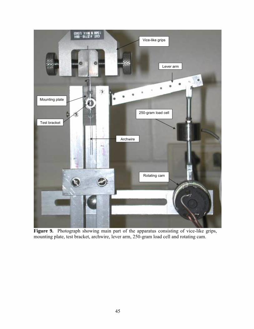
45
Lever arm
Vice-like grips
Mounting plate
Test bracket
Archwire
250-gram load cell
Rotating cam
Figure 9. Photograph showing main part of the apparatus consisting of vice-like grips, mounting plate, test bracket, archwire, lever arm, 250-gram load cell and rotating cam.
Test Bracket-Archwire Alignment
The test bracket-rod assembly was inserted through the hole in the mounting
plate. The test bracket was passed through the template hole and then an archwire was
inserted through all three bracket slots in a vertical manner (Figure 10). Prior to each
trial, the test bracket and archwire were wiped with alcohol to remove any residue and
then air-dried. The bracket-rod assembly could be rotated clockwise, counter-clockwise,
in and out to aid in further passive archwire engagement in the bracket slot; therefore,
negating the 2o tip in the Damon 2 and In-Ovation brackets. Once the proper alignment
was achieved, the bracket-rod assembly, which was attached to the lever arm, was
secured to prevent any additional movement.
At this time, an elastomeric tie (Ormco, Power O Mini-Stik, 0.120, Item #640-
1265, Lot #8J3) was ligated around the Minitwin or Transcend 6000 brackets or the gates
of the Damon 2 and In-Ovation brackets were closed. The vice-like grips of the Instron
machine engaged 5 mm of the archwire, and the distance from the vice-like grips to the
center of the test bracket was measured at 25 mm. Since the Instron machine pulled the
archwire superiorly through the bracket slots, the distance between the vice-like grips and
center of the test bracket were brought down to less than 25 mm, and then returned to 25
mm to allow the entire apparatus, especially the forces between the archwire and
elastomeric ties, to be pulled in the same direction as the archwire. Before the trial
commenced, the vice-like grips were once again released from the archwire and then re-
engaged to ensure passivity.
46
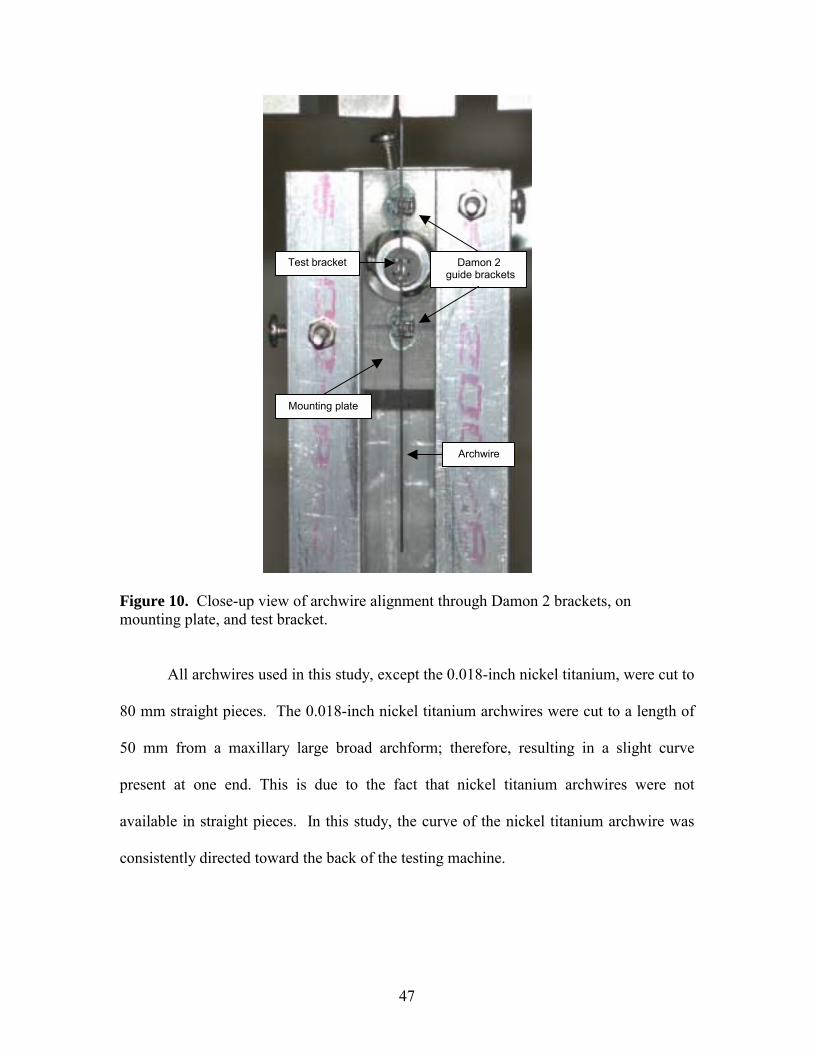
47
Mounting plate
Test bracket Damon 2 guide brackets
Archwire
Figure 10. Close-up view of archwire alignment through Damon 2 brackets, on mounting plate, and test bracket.
All archwires used in this study, except the 0.018-inch nickel titanium, were cut to
80 mm straight pieces. The 0.018-inch nickel titanium archwires were cut to a length of
50 mm from a maxillary large broad archform; therefore, resulting in a slight curve
present at one end. This is due to the fact that nickel titanium archwires were not
available in straight pieces. In this study, the curve of the nickel titanium archwire was
consistently directed toward the back of the testing machine.
48
Load Cells and Computer Setup
Prior to data collection, a 50-gram weight was used to calibrate the 250-gram load
cell (Sensotec, Inc. Model 31/1435-03). This load cell measured the load required to tip
the bracket/archwire to an angulation of 20o. It was interfaced with a custom built
computer containing an Intel Celeron processor and Labtech software (Laboratory
Technologies Corporation 1999, Labtech Control Version 11, Universal) recording all
the data. It was attached superiorly to the lever arm and inferiorly to the rotating cam,
which created the variable moments. The load cell was attached to the lever arm at a
distance of 10 cm from the lever arm�s center of rotation, which was directly behind the
test bracket-rod assembly. The lever arm movement was measured, with a protractor, to
have an oscillation range of 20o due to the rotating cam.
The second load cell, ±1 kN (Instron, UK 598) located on top of the Instron
machine, was calibrated with a 1000-gram weight. This load cell recorded the friction at
the bracket-archwire interface. This load cell was also interfaced with the same custom
built computer utilizing the Labtech software as the 250-gram load cell. A Gateway
E3000 system containing Merlin software (Instron Merlin Program, Version 3.23)
controlled the crosshead speed of the archwire (5mm/min).
DC Power Supply
A DC Power Supply (Maxtel International Corporation, BK Precision, Triple
Output DC Power Supply 1651) was connected to the rotating cam that oscillated the
lever arm to produce the variable moments. It was set at 11 volts, which correlated to 1
Hertz or 60 cycles/minute (Figure 11). This simulated the chewing frequency in humans.
49
As the rotating cam moved cyclically, the measured load would change correspondingly.
When the cam was rotated to its highest vertical dimension, the minimum load was
applied. Conversely, when the cam was rotated to its smallest vertical dimension, the
maximum load was applied. The connection of the lever arm to the rotating cam was
positioned to vary the load from zero to the resulting maximum. Before the archwire was
engaged in the test bracket, the rotating cam was turned until the 250-gram load cell was
at its most superior position (i.e. at 12 o�clock), the minimum load.
Bridge Amplifiers
Two bridge amplifiers were used in this study to provide excitation for the load
cells and to amplify the signal voltage (proportional to load) (Fig 11). The Signal
Conditioning Amplifier (Measurements Group, Instruments Division, Model 2311)
attached to the ±1 kN load cell, to measure friction, was reset to zero prior to each trial.
The second amplifier (Sensotec, Inc., Signal Conditioner-Indicator, Model GM), used to
measure load and connected to the 250-gram load cell, was not reset to zero prior to each
trial. Instead, with the load data transferred into Microsoft Excel 2000, the first 10
seconds was averaged and this value was then subtracted from all the load data to
compensate for offset and any noise present, with no crosshead movement, within the
apparatus. The subtracted load data was then multiplied by 10, due to the 10 cm lever arm
length, to obtain the true moment.
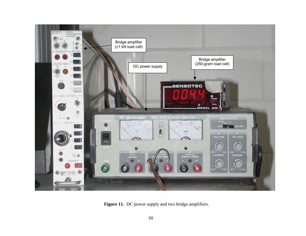
Figure 11. DC power supply and two bridge amplifiers.
Bridge amplifier (±1 kN load cell)
Bridge amplifier (250-gram load cell) DC power supply
50
Test Trial Intervals
Each trial was 60 seconds in length and the intervals are provided below: 0-10 seconds noise /offset (no archwire pull and no variable moments)
10 seconds begin archwire pull at a crosshead speed of 5 mm/min for 40
seconds
20 seconds rotating cam turned on to produce variable moments for 40
seconds
50 seconds archwire pull stopped; cam rotation continued
60 seconds rotating cam turned off; data collection completed
After each trial, the archwire and test bracket-rod assembly were removed and
replaced with new ones.
Trials were also performed with the absence of a test bracket while an archwire
was inserted in the slots of the two guide Damon 2 brackets on the mounting plate. This
was tested to measure the amount of load and friction caused by the Damon 2 guide
brackets and the test apparatus.
Data Collection and Evaluation
As stated above, all data was collected (DC voltages) and scaled by the computer
using Labtech software. Each bracket-archwire combination was tested 5 times;
therefore, a total of 120 trials were performed. Measurements were taken every tenth of a
second (0.10 seconds/measurement) for 60 seconds for both load and friction values.
Load was in units of gram-centimeters, due to the lever arm length, while friction was in
51
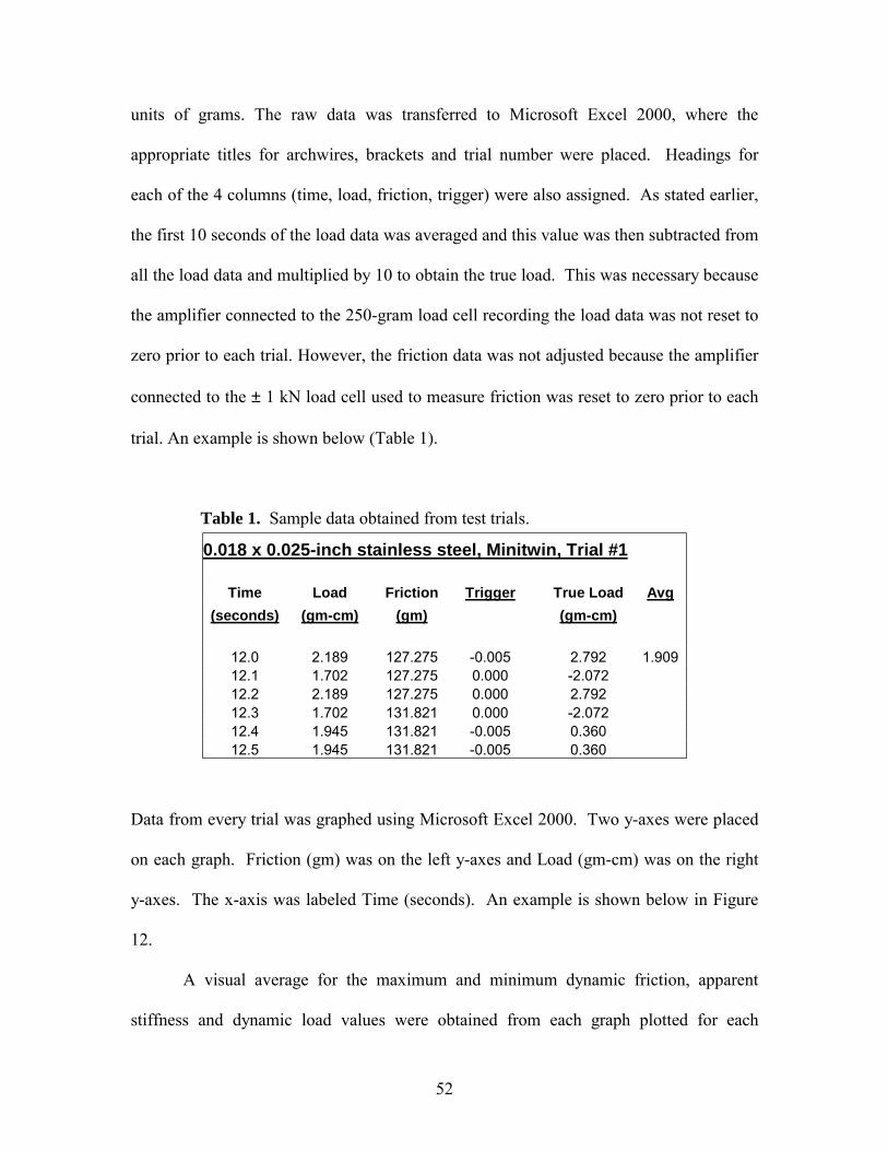
52
units of grams. The raw data was transferred to Microsoft Excel 2000, where the
appropriate titles for archwires, brackets and trial number were placed. Headings for
each of the 4 columns (time, load, friction, trigger) were also assigned. As stated earlier,
the first 10 seconds of the load data was averaged and this value was then subtracted from
all the load data and multiplied by 10 to obtain the true load. This was necessary because
the amplifier connected to the 250-gram load cell recording the load data was not reset to
zero prior to each trial. However, the friction data was not adjusted because the amplifier
connected to the ± 1 kN load cell used to measure friction was reset to zero prior to each
trial. An example is shown below (Table 1).
Table 1. Sample data obtained from test trials.
Data from every trial was graphed using Microsoft Excel 2000. Two y-axes were placed
on each graph. Friction (gm) was on the left y-axes and Load (gm-cm) was on the right
y-axes. The x-axis was labeled Time (seconds). An example is shown below in Figure
12.
A visual average for the maximum and minimum dynamic friction, apparent
stiffness and dynamic load values were obtained from each graph plotted for each
0.018 x 0.025-inch stainless steel, Minitwin, Trial #1
Time Load Friction Trigger True Load Avg (seconds) (gm-cm) (gm) (gm-cm)
12.0 2.189 127.275 -0.005 2.792 1.909 12.1 1.702 127.275 0.000 -2.072 12.2 2.189 127.275 0.000 2.792 12.3 1.702 131.821 0.000 -2.072 12.4 1.945 131.821 -0.005 0.360 12.5 1.945 131.821 -0.005 0.360
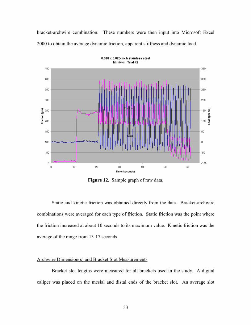
53
bracket-archwire combination. These numbers were then input into Microsoft Excel
2000 to obtain the average dynamic friction, apparent stiffness and dynamic load.
0.018 x 0.025-inch stainless steelMinitwin, Trial #2
0
50
100
150
200
250
300
350
400
450
0 10 20 30 40 50 60Time (seconds)
Fric
tion
(gm
)
-100
-50
0
50
100
150
200
250
300
350
Load
(gm
-cm
)Friction
Load
Figure 12. Sample graph of raw data.
Static and kinetic friction was obtained directly from the data. Bracket-archwire
combinations were averaged for each type of friction. Static friction was the point where
the friction increased at about 10 seconds to its maximum value. Kinetic friction was the
average of the range from 13-17 seconds.
Archwire Dimension(s) and Bracket Slot Measurements
Bracket slot lengths were measured for all brackets used in the study. A digital
caliper was placed on the mesial and distal ends of the bracket slot. An average slot
54
length was obtained for each bracket. A digital caliper was also used to measure the
archwire dimension(s) for all archwires used in this study. Once again, an average
archwire dimension was calculated.
Data Analysis
Data was analyzed to compare:
1) static, kinetic and dynamic friction
2) dynamic friction and dynamic load
3) dynamic load and apparent stiffness
4) bracket slot lengths
5) archwire sizes
6) contact angles
Statistics
JMP version 3.1.5 statistical analysis software was used to calculate ANOVA
(p<0.0001) and Tukey-Kramer Honest Significant Difference (HSD) (p<0.05). Microsoft
Excel 2000 was used to calculate the average and standard deviation.
Wire Stiffness Chart
A wire stiffness chart was provided by Ormco. It was used to analyze the results
obtained from this study. A portion of the chart is provided below in Table 2. Due to the
vertical orientation of the bracket slot, the variable moments placed at the bracket-
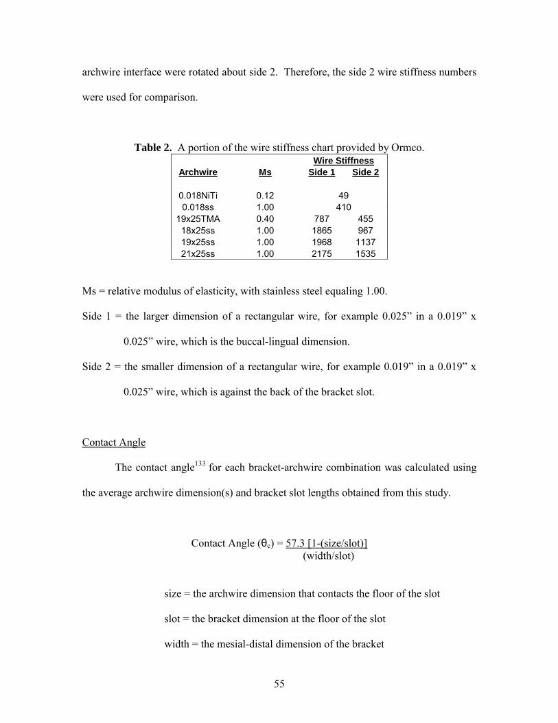
55
archwire interface were rotated about side 2. Therefore, the side 2 wire stiffness numbers
were used for comparison.
Table 2. A portion of the wire stiffness chart provided by Ormco. Wire Stiffness Archwire Ms Side 1 Side 2
0.018NiTi 0.12 49 0.018ss 1.00 410
19x25TMA 0.40 787 455 18x25ss 1.00 1865 967 19x25ss 1.00 1968 1137 21x25ss 1.00 2175 1535
Ms = relative modulus of elasticity, with stainless steel equaling 1.00. Side 1 = the larger dimension of a rectangular wire, for example 0.025� in a 0.019� x
0.025� wire, which is the buccal-lingual dimension.
Side 2 = the smaller dimension of a rectangular wire, for example 0.019� in a 0.019� x
0.025� wire, which is against the back of the bracket slot.
Contact Angle The contact angle133 for each bracket-archwire combination was calculated using
the average archwire dimension(s) and bracket slot lengths obtained from this study.
Contact Angle (θc) = 57.3 [1-(size/slot)] (width/slot)
size = the archwire dimension that contacts the floor of the slot
slot = the bracket dimension at the floor of the slot
width = the mesial-distal dimension of the bracket
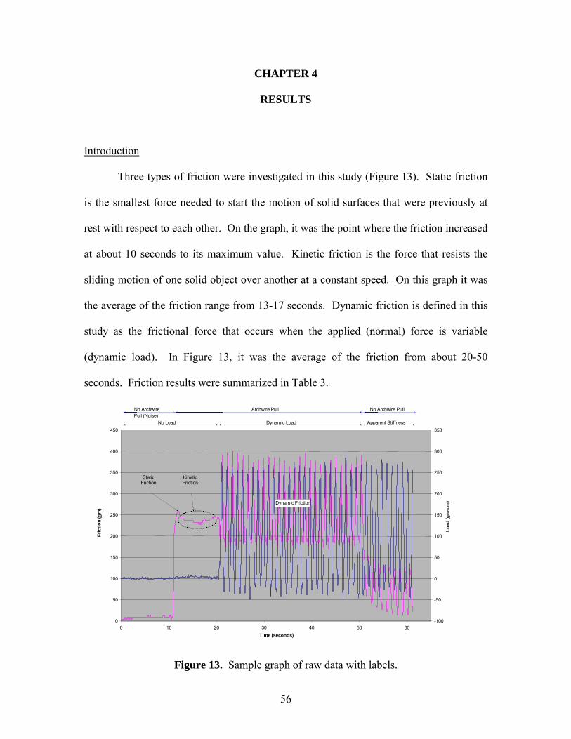
56
CHAPTER 4
RESULTS
Introduction
Three types of friction were investigated in this study (Figure 13). Static friction
is the smallest force needed to start the motion of solid surfaces that were previously at
rest with respect to each other. On the graph, it was the point where the friction increased
at about 10 seconds to its maximum value. Kinetic friction is the force that resists the
sliding motion of one solid object over another at a constant speed. On this graph it was
the average of the friction range from 13-17 seconds. Dynamic friction is defined in this
study as the frictional force that occurs when the applied (normal) force is variable
(dynamic load). In Figure 13, it was the average of the friction from about 20-50
seconds. Friction results were summarized in Table 3.
Figure 13. Sample graph of raw data with labels.
Dynamic Friction
0
50
100
150
200
250
300
350
400
450
0 10 20 30 40 50 60 Time (seconds)
Fric
tion
(gm
)
-100
-50
0
50
100
150
200
250
300
350 Lo
ad (g
m-c
m)
StaticFriction
Kinetic Friction
No Load Dynamic Load Apparent Stiffness No Archwire Pull (Noise) Archwire Pull No Archwire Pull
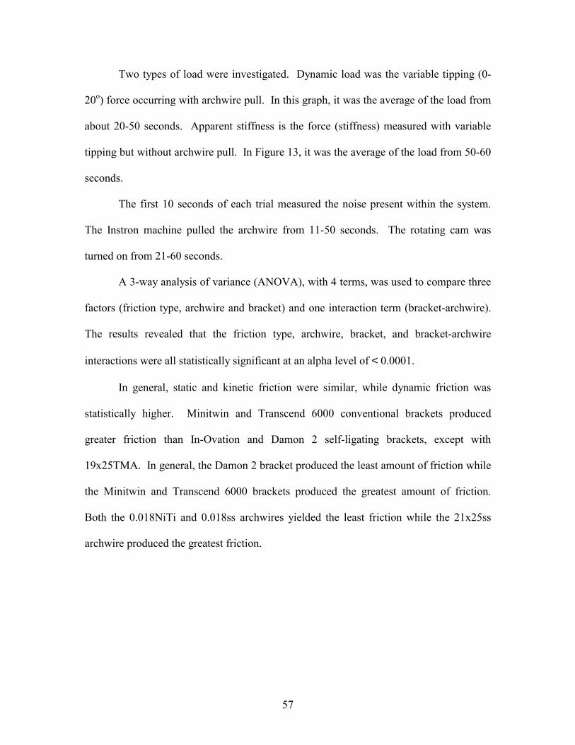
57
Two types of load were investigated. Dynamic load was the variable tipping (0-
20o) force occurring with archwire pull. In this graph, it was the average of the load from
about 20-50 seconds. Apparent stiffness is the force (stiffness) measured with variable
tipping but without archwire pull. In Figure 13, it was the average of the load from 50-60
seconds.
The first 10 seconds of each trial measured the noise present within the system.
The Instron machine pulled the archwire from 11-50 seconds. The rotating cam was
turned on from 21-60 seconds.
A 3-way analysis of variance (ANOVA), with 4 terms, was used to compare three
factors (friction type, archwire and bracket) and one interaction term (bracket-archwire).
The results revealed that the friction type, archwire, bracket, and bracket-archwire
interactions were all statistically significant at an alpha level of < 0.0001.
In general, static and kinetic friction were similar, while dynamic friction was
statistically higher. Minitwin and Transcend 6000 conventional brackets produced
greater friction than In-Ovation and Damon 2 self-ligating brackets, except with
19x25TMA. In general, the Damon 2 bracket produced the least amount of friction while
the Minitwin and Transcend 6000 brackets produced the greatest amount of friction.
Both the 0.018NiTi and 0.018ss archwires yielded the least friction while the 21x25ss
archwire produced the greatest friction.
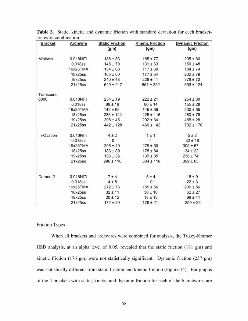
58
Table 3. Static, kinetic and dynamic friction with standard deviation for each bracket-archwire combination.
Bracket Archwire Static Friction Kinetic Friction Dynamic Friction (gm) (gm) (gm) Minitwin 0.018NiTi 188 ± 83 185 ± 77 205 ± 60 0.018ss 145 ± 70 131 ± 63 150 ± 48 19x25TMA 134 ± 68 117 ± 60 184 ± 74 18x25ss 185 ± 60 177 ± 54 232 ± 79 19x25ss 240 ± 48 226 ± 41 379 ± 72 21x25ss 649 ± 247 651 ± 252 693 ± 124 Transcend 6000 0.018NiTi 234 ± 19 222 ± 21 254 ± 30 0.018ss 89 ± 18 80 ± 14 155 ± 28 19x25TMA 142 ± 68 146 ± 56 230 ± 55 18x25ss 235 ± 122 225 ± 116 280 ± 76 19x25ss 298 ± 45 292 ± 34 455 ± 28 21x25ss 442 ± 128 460 ± 142 702 ± 178 In-Ovation 0.018NiTi 4 ± 2 1 ± 1 5 ± 2 0.018ss 0 -1 32 ± 18 19x25TMA 296 ± 49 279 ± 50 305 ± 57 18x25ss 183 ± 89 178 ± 84 134 ± 22 19x25ss 136 ± 36 139 ± 35 238 ± 74 21x25ss 296 ± 116 304 ± 118 399 ± 63 Damon 2 0.018NiTi 7 ± 4 5 ± 4 18 ± 9 0.018ss 4 ± 5 0 22 ± 3 19x25TMA 212 ± 76 181 ± 56 209 ± 56 18x25ss 32 ± 11 30 ± 10 62 ± 27 19x25ss 20 ± 12 18 ± 13 99 ± 41 21x25ss 172 ± 20 176 ± 21 259 ± 23
Friction Types
When all brackets and archwires were combined for analysis, the Tukey-Kramer
HSD analysis, at an alpha level of 0.05, revealed that the static friction (181 gm) and
kinetic friction (176 gm) were not statistically significant. Dynamic friction (237 gm)
was statistically different from static friction and kinetic friction (Figure 14). Bar graphs
of the 4 brackets with static, kinetic and dynamic friction for each of the 6 archwires are
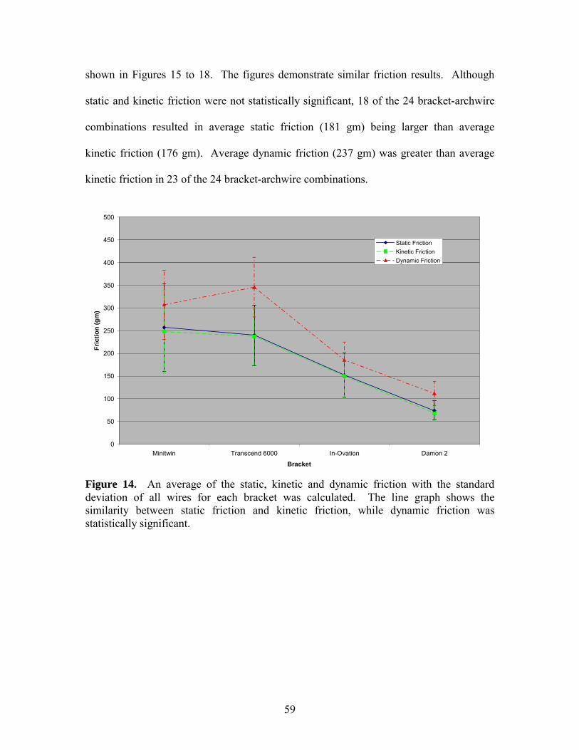
59
shown in Figures 15 to 18. The figures demonstrate similar friction results. Although
static and kinetic friction were not statistically significant, 18 of the 24 bracket-archwire
combinations resulted in average static friction (181 gm) being larger than average
kinetic friction (176 gm). Average dynamic friction (237 gm) was greater than average
kinetic friction in 23 of the 24 bracket-archwire combinations.
0
50
100
150
200
250
300
350
400
450
500
Minitwin Transcend 6000 In-Ovation Damon 2Bracket
Fric
tion
(gm
)
Static FrictionKinetic FrictionDynamic Friction
Figure 14. An average of the static, kinetic and dynamic friction with the standard deviation of all wires for each bracket was calculated. The line graph shows the similarity between static friction and kinetic friction, while dynamic friction was statistically significant.
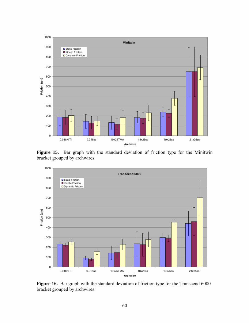
60
Minitwin
0
100
200
300
400
500
600
700
800
900
1000
0.018NiTi 0.018ss 19x25TMA 18x25ss 19x25ss 21x25ssArchwire
Fric
tion
(gm
)
Static FrictionKinetic FrictionDynamic Friction
Figure 15. Bar graph with the standard deviation of friction type for the Minitwin bracket grouped by archwires.
Transcend 6000
0
100
200
300
400
500
600
700
800
900
1000
0.018NiTi 0.018ss 19x25TMA 18x25ss 19x25ss 21x25ssArchwire
Fric
tion
(gm
)
Static FrictionKinetic FrictionDynamic Friction
Figure 16. Bar graph with the standard deviation of friction type for the Transcend 6000 bracket grouped by archwires.
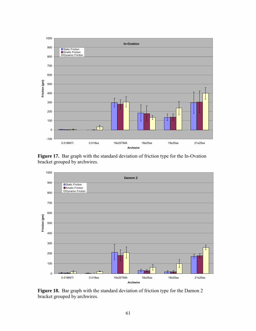
61
In-Ovation
-100
0
100
200
300
400
500
600
700
800
900
1000
0.018NiTi 0.018ss 19x25TMA 18x25ss 19x25ss 21x25ssArchwire
Fric
tion
(gm
)
Static FrictionKinetic FrictionDynamic Friction
Figure 17. Bar graph with the standard deviation of friction type for the In-Ovation bracket grouped by archwires.
Damon 2
0
100
200
300
400
500
600
700
800
900
1000
0.018NiTi 0.018ss 19x25TMA 18x25ss 19x25ss 21x25ssArchwire
Fric
tion
(gm
)
Static FrictionKinetic FrictionDynamic Friction
Figure 18. Bar graph with the standard deviation of friction type for the Damon 2 bracket grouped by archwires.
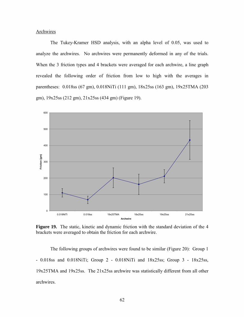
62
Archwires
The Tukey-Kramer HSD analysis, with an alpha level of 0.05, was used to
analyze the archwires. No archwires were permanently deformed in any of the trials.
When the 3 friction types and 4 brackets were averaged for each archwire, a line graph
revealed the following order of friction from low to high with the averages in
parentheses: 0.018ss (67 gm), 0.018NiTi (111 gm), 18x25ss (163 gm), 19x25TMA (203
gm), 19x25ss (212 gm), 21x25ss (434 gm) (Figure 19).
0
100
200
300
400
500
600
0.018NiTi 0.018ss 19x25TMA 18x25ss 19x25ss 21x25ss
Archwire
Fric
tion
(gm
)
Figure 19. The static, kinetic and dynamic friction with the standard deviation of the 4 brackets were averaged to obtain the friction for each archwire.
The following groups of archwires were found to be similar (Figure 20): Group 1
- 0.018ss and 0.018NiTi; Group 2 - 0.018NiTi and 18x25ss; Group 3 - 18x25ss,
19x25TMA and 19x25ss. The 21x25ss archwire was statistically different from all other
archwires.
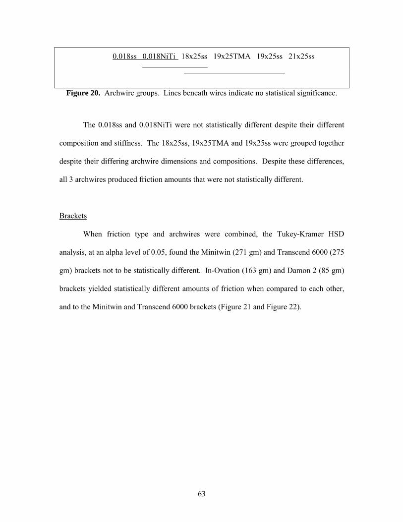
63
0.018ss 0.018NiTi 18x25ss 19x25TMA 19x25ss 21x25ss
Figure 20. Archwire groups. Lines beneath wires indicate no statistical significance.
The 0.018ss and 0.018NiTi were not statistically different despite their different
composition and stiffness. The 18x25ss, 19x25TMA and 19x25ss were grouped together
despite their differing archwire dimensions and compositions. Despite these differences,
all 3 archwires produced friction amounts that were not statistically different.
Brackets
When friction type and archwires were combined, the Tukey-Kramer HSD
analysis, at an alpha level of 0.05, found the Minitwin (271 gm) and Transcend 6000 (275
gm) brackets not to be statistically different. In-Ovation (163 gm) and Damon 2 (85 gm)
brackets yielded statistically different amounts of friction when compared to each other,
and to the Minitwin and Transcend 6000 brackets (Figure 21 and Figure 22).
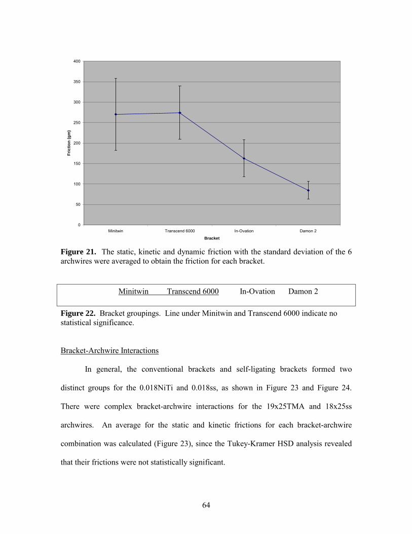
64
0
50
100
150
200
250
300
350
400
Minitwin Transcend 6000 In-Ovation Damon 2
Bracket
Fric
tion
(gm
)
Figure 21. The static, kinetic and dynamic friction with the standard deviation of the 6 archwires were averaged to obtain the friction for each bracket.
Minitwin Transcend 6000 In-Ovation Damon 2
Figure 22. Bracket groupings. Line under Minitwin and Transcend 6000 indicate no statistical significance.
Bracket-Archwire Interactions
In general, the conventional brackets and self-ligating brackets formed two
distinct groups for the 0.018NiTi and 0.018ss, as shown in Figure 23 and Figure 24.
There were complex bracket-archwire interactions for the 19x25TMA and 18x25ss
archwires. An average for the static and kinetic frictions for each bracket-archwire
combination was calculated (Figure 23), since the Tukey-Kramer HSD analysis revealed
that their frictions were not statistically significant.
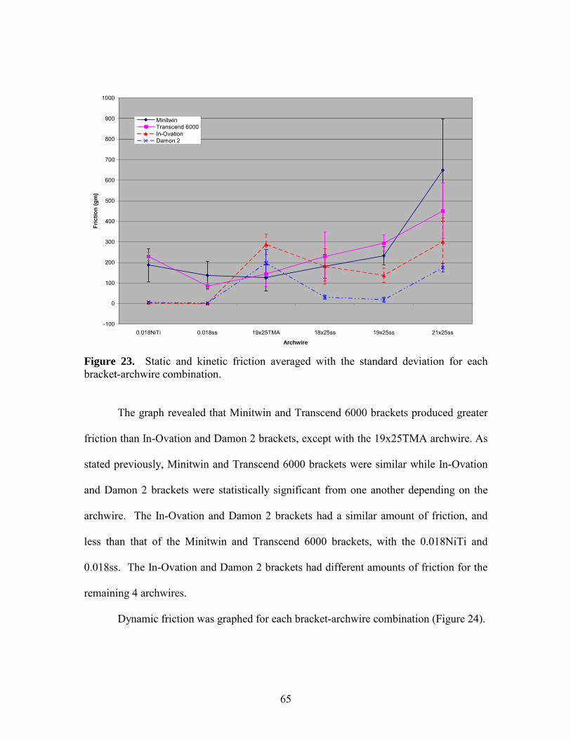
65
-100
0
100
200
300
400
500
600
700
800
900
1000
0.018NiTi 0.018ss 19x25TMA 18x25ss 19x25ss 21x25ss
Archwire
Fric
tion
(gm
)
MinitwinTranscend 6000In-OvationDamon 2
Figure 23. Static and kinetic friction averaged with the standard deviation for each bracket-archwire combination.
The graph revealed that Minitwin and Transcend 6000 brackets produced greater
friction than In-Ovation and Damon 2 brackets, except with the 19x25TMA archwire. As
stated previously, Minitwin and Transcend 6000 brackets were similar while In-Ovation
and Damon 2 brackets were statistically significant from one another depending on the
archwire. The In-Ovation and Damon 2 brackets had a similar amount of friction, and
less than that of the Minitwin and Transcend 6000 brackets, with the 0.018NiTi and
0.018ss. The In-Ovation and Damon 2 brackets had different amounts of friction for the
remaining 4 archwires.
Dynamic friction was graphed for each bracket-archwire combination (Figure 24).
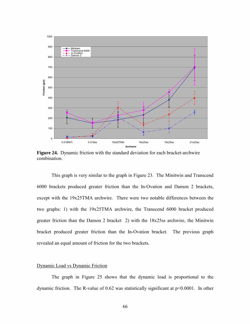
66
0
100
200
300
400
500
600
700
800
900
1000
0.018NiTi 0.018ss 19x25TMA 18x25ss 19x25ss 21x25ssArchwire
Fric
tion
(gm
)
MinitwinTranscend 6000In-OvationDamon 2
Figure 24. Dynamic friction with the standard deviation for each bracket-archwire combination.
This graph is very similar to the graph in Figure 23. The Minitwin and Transcend
6000 brackets produced greater friction than the In-Ovation and Damon 2 brackets,
except with the 19x25TMA archwire. There were two notable differences between the
two graphs: 1) with the 19x25TMA archwire, the Transcend 6000 bracket produced
greater friction than the Damon 2 bracket 2) with the 18x25ss archwire, the Minitwin
bracket produced greater friction than the In-Ovation bracket. The previous graph
revealed an equal amount of friction for the two brackets.
Dynamic Load vs Dynamic Friction
The graph in Figure 25 shows that the dynamic load is proportional to the
dynamic friction. The R-value of 0.62 was statistically significant at p<0.0001. In other
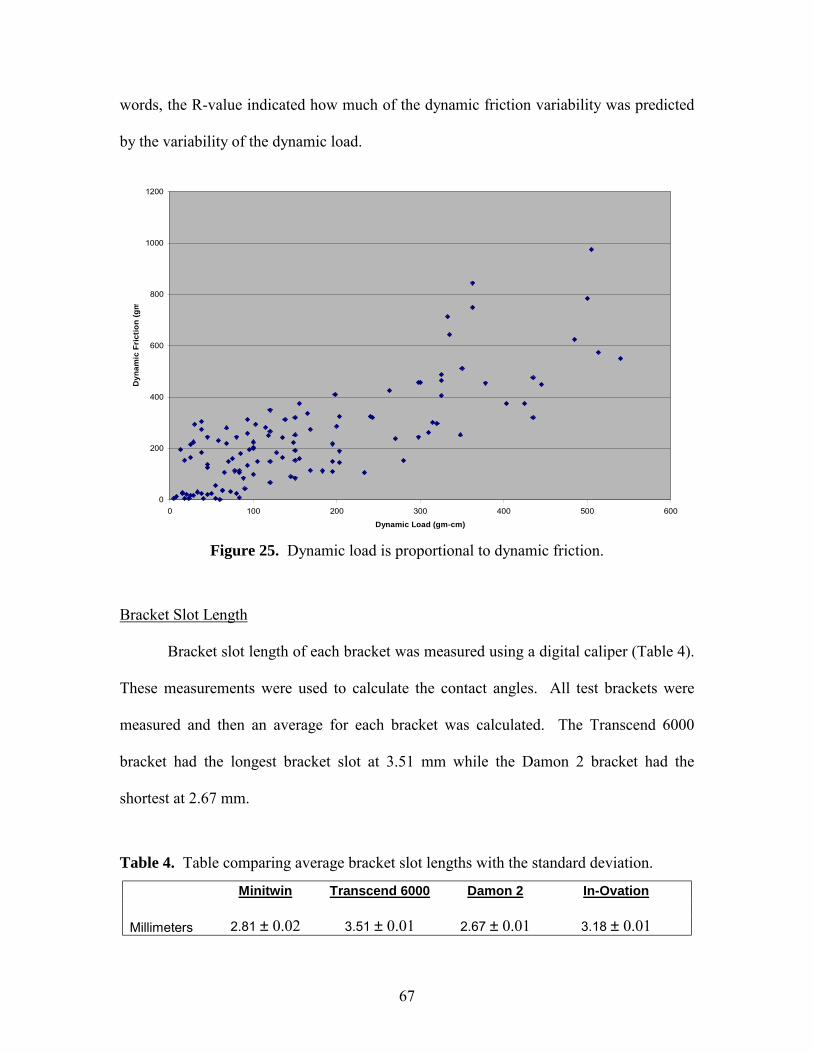
67
words, the R-value indicated how much of the dynamic friction variability was predicted
by the variability of the dynamic load.
0
200
400
600
800
1000
1200
0 100 200 300 400 500 600
Dynamic Load (gm-cm)
Dyn
amic
Fri
ctio
n (g
m
Figure 25. Dynamic load is proportional to dynamic friction.
Bracket Slot Length
Bracket slot length of each bracket was measured using a digital caliper (Table 4).
These measurements were used to calculate the contact angles. All test brackets were
measured and then an average for each bracket was calculated. The Transcend 6000
bracket had the longest bracket slot at 3.51 mm while the Damon 2 bracket had the
shortest at 2.67 mm.
Table 4. Table comparing average bracket slot lengths with the standard deviation.
Minitwin Transcend 6000 Damon 2 In-Ovation Millimeters 2.81 ± 0.02 3.51 ± 0.01 2.67 ± 0.01 3.18 ± 0.01
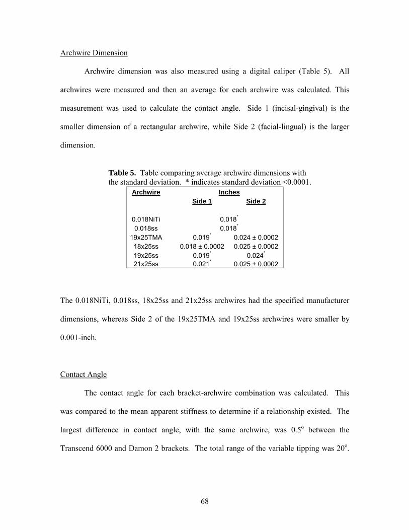
68
Archwire Dimension
Archwire dimension was also measured using a digital caliper (Table 5). All
archwires were measured and then an average for each archwire was calculated. This
measurement was used to calculate the contact angle. Side 1 (incisal-gingival) is the
smaller dimension of a rectangular archwire, while Side 2 (facial-lingual) is the larger
dimension.
Table 5. Table comparing average archwire dimensions with the standard deviation. * indicates standard deviation <0.0001.
Archwire Inches Side 1 Side 2 0.018NiTi 0.018*
0.018ss 0.018*
19x25TMA 0.019* 0.024 ± 0.0002 18x25ss 0.018 ± 0.0002 0.025 ± 0.0002 19x25ss 0.019* 0.024*
21x25ss 0.021* 0.025 ± 0.0002
The 0.018NiTi, 0.018ss, 18x25ss and 21x25ss archwires had the specified manufacturer
dimensions, whereas Side 2 of the 19x25TMA and 19x25ss archwires were smaller by
0.001-inch.
Contact Angle
The contact angle for each bracket-archwire combination was calculated. This
was compared to the mean apparent stiffness to determine if a relationship existed. The
largest difference in contact angle, with the same archwire, was 0.5o between the
Transcend 6000 and Damon 2 brackets. The total range of the variable tipping was 20o.
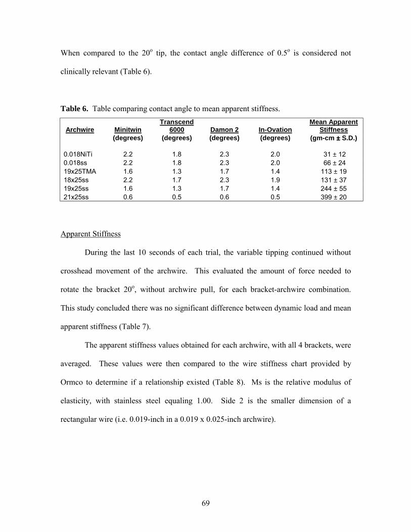
69
When compared to the 20o tip, the contact angle difference of 0.5o is considered not
clinically relevant (Table 6).
Table 6. Table comparing contact angle to mean apparent stiffness.
Archwire Minitwin Transcend
6000 Damon 2 In-Ovation Mean Apparent
Stiffness
(degrees)
(degrees)
(degrees)
(degrees)
(gm-cm ±±±± S.D.)
0.018NiTi 2.2 1.8 2.3 2.0 31 ± 12 0.018ss 2.2 1.8 2.3 2.0 66 ± 24 19x25TMA 1.6 1.3 1.7 1.4 113 ± 19 18x25ss 2.2 1.7 2.3 1.9 131 ± 37 19x25ss 1.6 1.3 1.7 1.4 244 ± 55 21x25ss 0.6 0.5 0.6 0.5 399 ± 20
Apparent Stiffness
During the last 10 seconds of each trial, the variable tipping continued without
crosshead movement of the archwire. This evaluated the amount of force needed to
rotate the bracket 20o, without archwire pull, for each bracket-archwire combination.
This study concluded there was no significant difference between dynamic load and mean
apparent stiffness (Table 7).
The apparent stiffness values obtained for each archwire, with all 4 brackets, were
averaged. These values were then compared to the wire stiffness chart provided by
Ormco to determine if a relationship existed (Table 8). Ms is the relative modulus of
elasticity, with stainless steel equaling 1.00. Side 2 is the smaller dimension of a
rectangular wire (i.e. 0.019-inch in a 0.019 x 0.025-inch archwire).
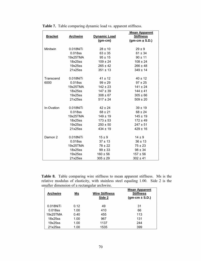
70
Table 7. Table comparing dynamic load vs. apparent stiffness.
Bracket Archwire Dynamic Load Mean Apparent
Stiffness (gm-cm) (gm-cm ±±±± S.D.) Minitwin 0.018NiTi 28 ± 10 29 ± 9 0.018ss 63 ± 35 61 ± 34 19x25TMA 95 ± 15 90 ± 11 18x25ss 109 ± 24 108 ± 24 19x25ss 265 ± 42 266 ± 48 21x25ss 351 ± 13 349 ± 14 Transcend 0.018NiTi 41 ± 12 40 ± 12 6000 0.018ss 99 ± 29 97 ± 25 19x25TMA 142 ± 23 141 ± 24 18x25ss 147 ± 39 144 ± 41 19x25ss 308 ± 67 305 ± 66 21x25ss 517 ± 24 509 ± 20 In-Ovation 0.018NiTi 42 ± 24 39 ± 19 0.018ss 68 ± 21 68 ± 24 19x25TMA 149 ± 19 145 ± 19 18x25ss 173 ± 53 172 ± 49 19x25ss 250 ± 50 247 ± 51 21x25ss 434 ± 19 429 ± 16 Damon 2 0.018NiTi 15 ± 9 14 ± 9 0.018ss 37 ± 13 36 ± 13 19x25TMA 78 ± 22 75 ± 23 18x25ss 99 ± 33 98 ± 34 19x25ss 160 ± 56 157 ± 56 21x25ss 305 ± 29 302 ± 41
Table 8. Table comparing wire stiffness to mean apparent stiffness. Ms is the relative modulus of elasticity, with stainless steel equaling 1.00. Side 2 is the smaller dimension of a rectangular archwire.
Archwire Ms Wire Stiffness Mean Apparent
Stiffness Side 2 (gm-cm ± S.D.)
0.018NiTi 0.12 49 31 0.018ss 1.00 410 66
19x25TMA 0.40 455 113 18x25ss 1.00 967 131 19x25ss 1.00 1137 244 21x25ss 1.00 1535 399
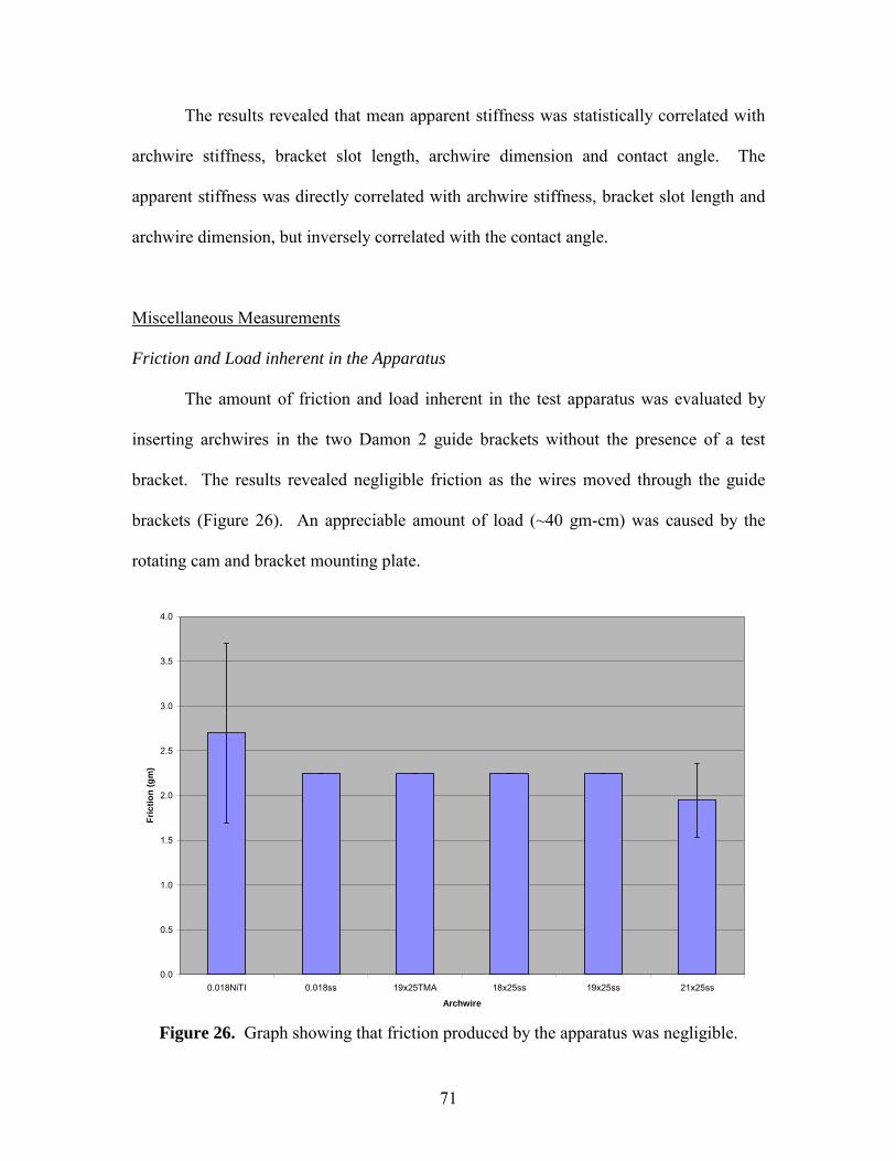
71
The results revealed that mean apparent stiffness was statistically correlated with
archwire stiffness, bracket slot length, archwire dimension and contact angle. The
apparent stiffness was directly correlated with archwire stiffness, bracket slot length and
archwire dimension, but inversely correlated with the contact angle.
Miscellaneous Measurements
Friction and Load inherent in the Apparatus
The amount of friction and load inherent in the test apparatus was evaluated by
inserting archwires in the two Damon 2 guide brackets without the presence of a test
bracket. The results revealed negligible friction as the wires moved through the guide
brackets (Figure 26). An appreciable amount of load (~40 gm-cm) was caused by the
rotating cam and bracket mounting plate.
0.0
0.5
1.0
1.5
2.0
2.5
3.0
3.5
4.0
0.018NiTI 0.018ss 19x25TMA 18x25ss 19x25ss 21x25ss
Archwire
Fric
tion
(gm
)
Figure 26. Graph showing that friction produced by the apparatus was negligible.
72
CHAPTER 5
DISCUSSION
Introduction
Many friction studies have been performed by attaching a bracket to a mechanical
testing machine that measured friction, while an archwire was pulled through the bracket
slot. This type of setup does not fully emulate the events that occur intraorally at the
bracket-archwire interface. The aim of this study was to simulate, more closely, the
effects of mastication on bracket-archwire interaction. More specifically, the friction
between 6 different archwires and 4 different brackets were investigated while variable
moments were placed at the bracket-archwire interface.
A 3-way ANOVA concluded that friction type, archwire, bracket and bracket-
archwire interactions were all statistically significant at an alpha level of <0.0001.
Friction Types
Static friction and kinetic friction were similar, while dynamic friction was
statistically significant. The dynamic friction was proportional to the dynamic load.
Previous research stated that static friction was greater than kinetic friction. In this study,
it did occur in 18 of the 24 bracket-archwire combinations. Static friction was 5 gm
greater than kinetic friction, but this difference when evaluated by the Tukey-Kramer
HSD analysis, at an alpha level of 0.05, was not statistically significant. Dynamic
friction was statistically significant and greater than kinetic friction in 23 of the 24
73
bracket-archwire combinations. Dynamic friction was 62 gm greater than kinetic
friction.
The static and kinetic friction were not statistically different, but these values
were obtained with an archwire being pulled passively through the bracket slot. This
finding may be different if a variable moment or an angle at the bracket-archwire
interface was applied.
These results are clinically significant whenever sliding mechanics is involved.
For tooth movement to occur, the static friction between the bracket and archwire must
be overcome. This is most often accomplished with orthodontic devices such as rubber
bands, powerchain and nickel-titanium coils pulling on the tooth. Once tooth movement
has begun, its movement is maintained if kinetic friction is overcome. Tooth translation
is a series of tipping movements involving crown tipping and then root uprighting. A
tooth does not translate linearly along an archwire. When the bracket on the tooth crown
is tipped in the direction it is being pulled, it will make contact with the archwire. It is at
this point where binding may occur at the bracket-archwire interface; thus, impeding
tooth movement. Therefore, a force must be placed at the bracket-archwire interface to
release the binding, in order for tooth movement to continue.
This study simulated mastication and its effects at the bracket-archwire interface.
Mastication, the impact of food on the archwire and bruxism can cause archwire
deflection or cuspal flexure. It was hypothesized that these factors would release the
binding that occurred at the bracket-archwire interface. The results revealed that a
binding and releasing effect occurred when a dynamic load, such as a variable moment
74
simulating mastication, was placed at the bracket-archwire interface; thus, enabling tooth
movement.
Variable moments tipped (rotated) the bracket to a total range of 20o, creating a
variable bracket-archwire angle. During each trial, the archwire was subjected to cyclical
binding and releasing actions against the bracket slot, due to bracket tipping. As binding
occurred, the friction increased until the tip was reversed in the opposite direction; thus,
releasing the binding and causing the friction to be reduced to less than that of kinetic
friction. Intraorally, release of any binding present at the bracket-archwire interface
would allow tooth movement. Such a reduction of dynamic friction seemed to be
independent of the bracket and archwire.
Only elastomeric ties and self-ligating clips were investigated; however, it would
appear that stainless steel ties would produce similar results. Therefore, the results of this
study do concur with those of O�Reilly,1 Braun83 and Liew.85 They stated that with
archwire deflection, frictional resistance was either reduced or momentarily became zero,
due to the release of binding.
Archwires
A generalized view of frictional resistance for each archwire was plotted in Figure
19 and the archwire groupings were indicated in Figure 20. The 0.018NiTi archwire was
similar to 0.018ss and 18x25ss archwires. Its dimension was similar to and friction
greater than 0.018ss, possibly due to the nickel-titanium content which produced greater
friction than stainless steel, as stated in previous
studies.7,14,17,18,21,30,33,35,39,41,45,48,52,53,57,58,59,72,88 However, as stated earlier, the difference
75
in friction between 0.018ss and 0.018NiTi were not always statistically significant.
Although the 0.018NiTi archwire had a smaller dimension than the18x25ss archwire, the
nickel-titanium content possibly increased the friction to approximate that of the18x25ss
archwire, depending on the bracket. The three archwires 18x25ss, 19x25TMA and
19x25ss were not statistically different, despite their differing cross-sections and
compositions.
The archwire with the highest friction was 21x25ss. For most test conditions, this
archwire produced friction that was much greater than the other 5 archwires. These
results indicated that when sliding mechanics were involved, smaller dimension
archwires produced less friction than larger dimension archwires. The choice of which
archwire to use for sliding mechanics also depends on the amount of tooth tip, torque and
angulation required. The bracket prescription would be expressed more if a larger sized
rectangular archwire was inserted into the bracket slot. Therefore, if one needs to
maintain the proper tooth tip, torque and angulation, an 18x25ss, 19x25ss or 21x25ss
archwire would be needed. If the amount of tooth translation is minimal, or tooth tip,
torque and angulation were not of concern, a 0.018ss archwire could be used due to its
low frictional resistance.
The average hardness values of the various archwires were provided by Ormco.
Vickers hardness values for stainless steel, TMA and nickel-titanium archwires were 479,
296 and 273, respectively. This indicated that the TMA and nickel-titanium archwire
were about 60% and 57% less hard than the stainless steel archwire, respectively.
Therefore, binding of the 19x25TMA archwire against the bracket would occur to a
76
greater degree when compared to 19x25ss, due to its reduction in hardness and greater
�gouging� of the surface.
Brackets
A Tukey-Kramer HSD analysis concluded that the Minitwin and Transcend 6000
brackets were similar. The In-Ovation and Damon 2 brackets were both statistically
different from one another and to the Minitwin and Transcend 6000 brackets. The slot of
the Minitwin bracket was composed of stainless steel while the slot of the Transcend
6000 bracket was made of ceramic. The older generation Transcend 2000 ceramic
bracket was found to have a rougher and more porous surface than stainless steel.30,55
The friction in the newer Transcend 6000 bracket was not statistically significant from
the Minitwin bracket in this study. This may be due to improved manufacturing
processes that yielded a surface that was smoother and had a similar frictional resistance
to stainless steel. When examined under a light microscope, the Transcend 2000 and
Transcend 6000 brackets both appeared to have a similar surface roughness. The mesial
and distal edges of both bracket slots were square; however, only the facial surface of the
Transcend 6000 bracket was rounded. Therefore, the belief that all ceramic brackets
produce greater friction than stainless steel brackets was not supported.
The In-Ovation and Damon 2 brackets were, in general, statistically different.
The In-Ovation bracket had an active self-ligating clip while the Damon 2 bracket had a
passive self-ligating clip. Both produced less friction than the Minitwin and Transcend
6000 brackets. The In-Ovation bracket �grabbed� at an archwire dimension of 0.018 x
0.025-inches when pulled with finger pressure, due to the active self-ligating clip. No
77
resistance was encountered with the Damon 2 bracket up to and including an archwire
dimension of 0.021 x 0.025-inches. This indicated that the active self-ligating clip of the
In-Ovation bracket would bind more to an archwire than the passive self-ligating clip of
the Damon 2 bracket. Therefore, higher friction would be encountered with the In-
Ovation bracket when 0.018 x 0.025-inch and greater archwire dimensions were inserted
into its bracket slot, when compared to the Damon 2 bracket. The active engagement of
the archwire into the bracket slot allows the tip, torque and in-out features of the In-
Ovation bracket to be more fully expressed than in the Damon 2 bracket.
Bracket-Archwire Interactions
When the static and kinetic frictions were averaged for each bracket-archwire
combination, the Minitwin and Transcend 6000 brackets produced higher levels of
friction than In-Ovation and Damon 2 brackets (Figure 23). This came as no surprise due
to previous research which concluded that conventional brackets tied with elastomerics or
steel ties produced greater friction than self-ligating brackets.23,65,88 When elastomers and
stainless steel ties were ligated to a bracket, the archwire was pushed into the bracket slot.
This increased the normal force acting on the archwire, which caused an increase in
friction. The debate on whether elastomers or steel ties produce greater friction has not
been concluded.
The two self-ligating brackets produced a similar amount of friction for both the
0.018NiTi and 0.018ss archwires because they passively slid through the closed bracket
slots. With the remaining rectangular archwires, the In-Ovation bracket produced greater
78
friction than the Damon 2 bracket, due to its active self-ligating clip which engaged the
archwire.
The In-Ovation and Minitwin brackets produced the same amount of friction with
the 18x25ss archwire. This could be due to the active self-ligting clip of the In-Ovation
bracket behaving like the elastomeric tie on the Minitwin bracket for the 18x25ss
archwire. Both may have exerted an equivalent amount of normal force on the archwire;
thus, producing a similar amount of friction.
The increased friction by the In-Ovation and Damon 2 brackets, over the
Minitwin and Transcend 6000 brackets, with the 19x25TMA may be due to the
composition of the archwire and the nature of ligation. The TMA material was less hard
and more flexible. The decreased hardness may play a significant role when comparing
the conventional brackets to the self-ligating brackets. With the conventional Minitwin
and Transcend 6000 brackets, the 19x25TMA archwire was pushed into the bracket slot
with an elastomeric tie, which was also soft and flexible. Since both the 19x25TMA and
elastomeric tie were both soft and flexible, any binding that may have occurred would
primarily happen at the bracket-archwire interface. Less binding would occur between
the archwire and the elastomeric tie.
However, with the self-ligating In-Ovation and Damon 2 brackets, they had a
stainless steel gate instead of an elastomeric tie. The stainless steel gates were hard,
inflexible and may have rough edges, compared to elastomeric ties. The In-Ovation
bracket produced greater friction than the Damon 2 bracket with the 19x25TMA. The In-
Ovation bracket had an active self-ligating clip, which was pushed up against the
19x25TMA archwire, which was soft and flexible. This may have caused the active clip
79
to dig into the 19x25TMA archwire; thus, creating binding and increasing friction. Since
the Damon 2 bracket had a passive self-ligating clip, it did not push up against the
19x25TMA archwire. Its metal gate formed the fourth wall to enclose the archwire, yet
still allowed it to freely move within the bracet slot. This fourth wall of the Damon 2
bracket, although being passive, was not soft and flexible like an elastomeric tie.
Therefore, the metal gate could still bind to the softer 19x25TMA archwire causing
increased friction.
The 19x25TMA archwire produced greater friction than the 18x25ss and 19x25ss
archwire in combination with the In-Ovation and Damon 2 brackets. This may be due to
the reasons given above. The 19x25TMA archwire material was less hard than that of
stainless steel. Therefore, the metal gates of both self-ligating brackets would bind more
to the TMA than stainless steel archwire.
In general, the conventional brackets and self-ligating brackets formed two
distinct groups for the 0.018NiTi and 0.018ss in Figure 23 and Figure 24. The Minitwin
and Transcend 6000 brackets yielded greater friction than the In-Ovation and Damon 2
brackets. This is due to the small archwire dimension, which passively inserts through
the In-Ovation and Damon 2 bracket slots, but is actively held against the bracket slot for
the Minitwin and Transcend 6000 brackets by an elastomeric tie. Therefore, friction was
greater with the conventional brackets.
Dynamic Load vs Dynamic Friction
As the slope of the dynamic load increased, the slope of the dynamic friction also
increased, and vice-versa. Therefore, it appeared that both dynamic load and dynamic
80
friction were synchronized. O�Reilly1 found the relationship between displacement and
friction to be linear. Braun83 stated that reduction of frictional resistance was
proportional to the magnitude of the oscillations.
Archwire Dimension
The archwire dimension was measured in order to calculate the contact angle. All
archwires were measured to the manufacturer specifications, except the 19x25TMA and
19x25ss archwire which were 0.001-inch smaller on the larger dimension of the archwire.
In this study, the variable moments placed at the bracket-archwire interface were rotated
about side 2, which is the larger dimension of a rectangular archwire. Therefore, the side
2 wire stiffness numbers were used for comparison.
Bracket Slot Length
The bracket slot length was measured in order to calculate the contact angle.
Although the Minitwin and Transcend 6000 brackets were not statistically different for
friction, the difference in bracket slot length was 0.70 mm. The In-Ovation bracket was
0.37 mm greater in bracket slot length then the Minitwin bracket; however, in general,
the In-Ovation bracket produced less friction. This would indicate that bracket slot
length alone did not influence frictional resistance. However, the bracket slot length
would affect the interbracket distance. A wide bracket slot would lead to a decreased
interbracket distance, and this would aid in rotation corrections. A narrow bracket slot
would lead to an increased interbracket distance, and this would aid in archwire
engagement into the bracket slot.
81
Contact Angle
The contact angle was measured using Kusy�s formula.133 As the contact angle
increased, from 0.5o to 2.3o, there was a general trend for decreased mean apparent
stiffness. The smallest contact angle was between the Transcend 6000 and In-Ovation
brackets with the 21x25ss archwire. The largest contact angle was between the Damon 2
bracket and the 0.018NiTi, 0.018ss and 18x25ss archwires. These results are due to the
size of the archwire and bracket slot.
If the bracket was tipped less than the contact angle, binding would not occur.
However, if the bracket was tipped more than the contact angle, binding would occur and
consequently, friction would increase.
Apparent Stiffness
There was no difference between the dynamic load and apparent stiffness. This
indicated that when variable moments were placed at the bracket-archwire interface, with
or without the archwire being pulled, the load stayed constant. Hence, archwire pull did
not influence the dynamic load or apparent stiffness.
There was a direct correlation between archwire stiffness, bracket slot length and
archwire dimension and an inverse correlation with contact angle to apparent stiffness.
The archwire stiffness, archwire dimension and contact angle were inter-related to a great
degree.
The variable moment created a maximum bracket-archwire angle of 20o for all
trials. Therefore, the load necessary to achieve this constant angle would vary with
archwire stiffness. More flexible materials such as nickel-titanium and TMA require less
82
force to create the bracket-archwire angle of 20o, when compared to stainless steel
archwires. The 19x25TMA archwire produced a mean apparent stiffness that was half
that of the 19x25ss archwire.
The size and shape of the archwire contributed to the apparent stiffness as well.
When comparing 0.018ss (66 gm-cm) to 18x25ss (131 gm-cm), the rectangular archwire
had more apparent stiffness than the round wire. The 18x25ss (131 gm-cm) had less
apparent stiffness than the 19x25ss (244 gm-cm), even though the difference in archwire
dimension was just 0.001-inch on only one side. Therefore, as the archwire dimension
increased, both the archwire stiffness increased and the contact angle decreased; thus,
producing a greater apparent stiffness.
Miscellaneous Measurements
Friction and Load inherent in the Apparatus
The amount of friction inherent within the friction testing apparatus was
negligible (2.1 gm); therefore, the friction obtained from every trial was friction at the
bracket-archwire interface.
However, the amount of load inherent within the tipping apparatus was
appreciable (40 gm-cm). Since this value was consistent for all trials (and could have
been subtracted from every trial) the results were valid.
One of the goals of this study was to evaluate for friction trends between 6
archwires and 4 brackets, not raw data values. Previous studies that measured friction
involving archwire deflection were performed with different set-ups and therefore,
obtained different raw data. Hence, the results of this study may not coincide with other

83
investigations. The results from this study would aid orthodontists in their selection of
which bracket-archwire combination would be the most efficient when performing
sliding mechanics.
84
Clinical Implications
As with all in vitro studies, the results may vary with what actually occurs in vivo.
However, since it is nearly impossible to replicate variable moments intraorally at the
bracket-archwire interface, the results obtained from this study are the most realistic yet.
Most of the previous studies have pulled an archwire through a bracket slot in a linear
fashion; thus, not simulating the variable moments that occur intraorally during
mastication. The results from this study indicate that during mastication, a binding and
releasing effect occur at the bracket-archwire interface. In other words, when sliding
mechanics is involved, binding between the bracket and archwire may occur, which will
impede further tooth movement, until the binding is released.
It is known that tooth translation is a series of tipping movements. For example,
if canine retraction is desired, its crown is tipped distally until the bracket contacts the
archwire. Then the root is uprighted by being tipped distally. Thus, tooth translation is a
series of crown tipping and root uprighting. When the bracket on the crown of the tooth
tips to contact the archwire, it is at this interface where binding can occur. The root
cannot upright itself until the binding is released; hence, tooth translation is stopped.
Therefore, during mastication, when food impacts the archwire causing it to deflect or
cuspal flexure occurs, it may release the binding that may be present at the bracket-
archwire interface; thus, allowing tooth movement to continue.
This phenomenon was seen in the study. When the bracket was tipped, the
archwire contacted the edges of the bracket slot causing friction to increase. However,
when the bracket was tipped in the opposite direction, similar to archwire deflection
85
during mastication, the friction decreased due to the release of binding. As a result,
sliding mechanics occurred.
These results indicate that tooth translation involves many factors such as
archwire dimension and composition, bracket composition, method of ligation, binding,
archwire deflection and cuspal flexure. Although this study was performed in vitro,
many of the results can be applied in vivo. The choice of which bracket and archwire to
use for sliding mechanics influences the efficiency of tooth movement. This study
revealed that self-ligating brackets produced less friction than conventional brackets.
Therefore, if friction is to be minimized, the In-Ovation and Damon 2 self-ligating
brackets should be used in place of the Minitwin and Transcend 6000 brackets. The
round archwires produced less friction than the rectangular archwires. During tooth
translation, stainless steel archwires are most often used, due to their stiffness. Therefore,
the round 0.018-inch stainless steel archwire should be used to minimize friction.
However, if a rectangular stainless steel archwire is used during sliding mechanics, the
smallest dimension archwire would yield the least amount of friction.
86
Future Studies
A repeat of this study with other brackets and archwires would be beneficial.
Although the Transcend 6000 bracket was tested in this study, its use has declined due to
the popularity of the new Clarity brackets, also produced by Unitek. This and other
esthetic brackets, with and without a stainless steel slot, composed of different materials
such as plastic and ceramic, could be investigated to evaluate their influence on friction.
With self-ligating brackets, there is no need for elastomeric ties; however, some
children want colors to be placed on the brackets, and this is routinely done. A study to
investigate frictional differences in self-ligating brackets with and without an elastomeric
tie could be performed. A self-ligating esthetic bracket could be tested to determine if the
friction is more similar to ceramic brackets or self-ligating brackets.
87
CHAPTER 6
SUMMARY AND CONCLUSIONS
The purpose of this study was to determine whether self-ligating brackets
exhibited less friction than stainless steel and ceramic brackets when subjected to variable
moments. Few studies have investigated the influence of mastication, archwire
deflection and cuspal flexure on friction at the bracket-archwire interface.
Statistical analysis was performed using ANOVA (p<0.0001) and Tukey-Kramer
HSD (p<0.05). Friction types, archwires, brackets, bracket-archwire interactions and
apparent stiffness were evaluated. Bracket slot length, archwire dimension and contact
angle were measured.
The following general conclusions were made:
1) Static and kinetic friction were similar, while dynamic friction was statistically
different.
2) The following groups of archwires produced similar friction: 1) 0.018ss and
0.018NiTi 2) 18x25ss, 19x25TMA and 19x25ss 3) 21x25ss
3) The Minitwin and Tanscend 6000 brackets produced a similar amount of friction,
while the In-Ovation and Damon 2 brackets were statistically different from one
another and to the Minitwin and Transcend 6000 brackets.
88
The following specific conclusions were made:
1) Bracket-archwire interactions
a. The conventional Minitwin and Transcend 6000 brackets produced greater
friction than the self-ligating In-Ovation and Damon 2 brackets, except
with the 19x25TMA archwire.
b. In-Ovation and Damon 2 brackets produced similar amounts of friction
with 0.018NiTi and 0.018ss archwires.
c. Dynamic friction was momentarily reduced below kinetic friction. It was
at this point where binding at the bracket-archwire interface was released.
2) Dynamic load was proportional to dynamic friction.
3) Contact angle and bracket slot length did not greatly influence frictional
resistance, for the conditions of this study.
89
CHAPTER 7
RECOMMENDATIONS FOR FUTURE RESEARCH
Upon completion of this study, the following were recommended:
1) Using brackets with 0o torque and 0o tip would facilitate and ensure that the
brackets, when mounted onto the acrylic rods, were properly aligned.
2) The 0.018NiTi used in this study was cut from a preformed archwire; thus,
leaving one end curved. If a straight piece of nickel-titanium wire, with the same
length as the other archwires being investigated, can be found, this would
eliminate one variable from the current study.
3) The Instron machines� vice-like grips, that hold the archwire, were serrated.
Having a smooth surface grip would prevent any bending of the archwire that
may occur. This would ensure total passivity of the archwire through the bracket
slots.
4) The friction-test apparatus was designed and built to be user friendly. When the
test brackets and archwires were passively aligned, many small adjustments were
still necessary. This increased the time required to perform the study.
Redesigning the test-apparatus to minimize the numerous small adjustments
necessary to ensure bracket-archwire passivity would improve efficiency
90
REFERENCES 1. O'Reilly D, Dowling PA, Lagerstrom L. An Ex Vivo Investigation into the Effect of
Bracket Displacement on the Resistance to Sliding. Br Journal Orthod 1999;26(3):219-27.
2. Bowden FP, Tabor D. Friction - An Introduction to Tribology. 1974, London:
Heinemann. 3. Omana HM, Moore RN, Bagby MD. Frictional Properties of Metal and Ceramic
Brackets. J Clin Orthod 1992;26(7):425-32. 4. Serway RA. Physics: For Scientists and Engineers. Vol. 82. 1982, Philadelphia:
Saunders College Publishing. 5. Tipler PA. Physics. Vol.156.1978, New York: Worth Publishers, Inc. 6. Baker KL et al. Frictional Changes in Force Values Caused by Saliva Substitution.
Am J Orthod Dentofacial Orthop 1987;91:316-20. 7. Stannard JG, Gau JM, Hanna M. Comparative Friction of Orthodontic Wires Under
Dry and Wet Conditions. Am J Orthod Dentofacial Orthop 1986;89:485-91. 8. Frank CA, Nikolai RJ. A Comparative Study of Frictional Resistances Between
Orthodontic Bracket and Arch Wire. Am J Orthod Dentofacial Orthop 1980;78:593-09.
9. Kapur R, Sinha PK, Nanda RS. Comparison of Frictional Resistance in Titanium and
Stainless Steel Brackets. Am J Orthod Dentofacial Orthop 1999;116:271-74. 10. Rabinowicz E. Friction and Wear of Materials.1965, New York: John Wiley & Sons,
Inc. 56-62. 11. Bowden FP, Tabor D. The Friction and Lubrication of Solids.1950, Oxford:
Clarendon Press.149-51. 12. Kusy RP, Whitley JQ. Friction Between Different Wire-Bracket Configurations and
Materials. Semin Orthod 1997;3:166-77. 13. Pizzoni L, Ravnholt G, Melsen B. Frictional Forces Related to Self-ligating Brackets.
Eur J Orthod 1998;20:283-91. 14. Drescher D, Bourauel C, Schumacher HA. Frictional Forces Between Brackets and
Arch Wires. Am J Orthod Dentofacial Orthop 1989;96:397-04.
91
15. Loftus BP. et al. Evaluation of Friction During Sliding Tooth Movement in Various
Bracket-Arch Wire Combinations. Am J Orthod Dentofacial Orthop, 1999. 116(3): p. 336-45.
16. Jastrzebski AD. Nature and Properties of Engineering Materials. 1959, New York:
John Wiley & Sons, Inc. 17. Kapila S, et al. Evaluation of Friction Between Edgewise Stainless Steel Brackets and
Orthodontic Wires of Four Alloys. Am J Orthod Dentofacial Orthop 1990;98:117-26. 18. Tidy DC. Frictional Forces in Fixed Appliances. Am J Orthod Dentofacial Orthop
1989;96:249-54. 19. Andreasen GF, Quevedo FR. Evaluation of Friction Forces in the 0.022 x 0.028
Edgewise Bracket In Vitro. J Biomech 1970.3:151-60. 20. Peterson L, Spencer R, Andreasen GF. A Comparison of Friction Resistance for
Nitinol and Stainless Steel Wire in Edgewise Brackets. 1982;13:563-71: Quintesscence International.
21. Garner LD, Allai WW, Moore BK. A Comparison of Frictional Forces During
Simulated Canine Retraction of a Continuous Edgewise Arch Wire. Am J Orthod Dentofacial Orthop 1986;90:199-03.
22. Echols PM. Elastic Ligatures: Binding Forces and Anchorage Taxation. Am J Orthod
Dentofacial Orthop 1975;67:219-20. 23. Berger JR, Grundemann GW, Sandrik JL. A Comparative Study of Frictional Forces
Between Orthodontic Brackets and Arch Wires. Am J Orthod Dentofacial Orthop 1991;97:219-28.
24. Paulson RC, Speidel TM, Isaacson RJ. A Laminographic Study of Cuspid Retraction
versus Molar Anchorage Loss. Angle Orthod 1970; 40:20-27. 25. Greenberg AR, Kusy RP. A Survey of Specialty Coatings for Orthodontic Wires. J
Dent Research 1979;58:A21. 26. Proffit WR. Contemporary Orthodontics. 1986, St. Louis: C.V. Mosby Company. 27. Keith O, Kusy RP, Whitlye JQ. Zirconia brackets: An evaluation of Morphology and
Coefficients of Friction. Am J Orthod Dentofacial Orthop 1994;106:605-14. 28. Halderson H. Routine Use of Minute Forces. Am J Orthod Dentofacial Orthop
1975;43:750-68.
92
29. An Engineers Guide to Friction: Defense Metals Information Center. Vol. DMIC
Memorandum 246. 1970, Columbus, Ohio: Batelle Memorial Institute. 30. Pratten DH, et al. Frictional Resistance of Ceramic and Stainless Steel Orthodontic
Brackets. Am J Orthod Dentofacial Orthop, 1990;98:398-03. 31. Palmer. Friction. Scientific American 1951;184:54-60. 32. Kusy RP, Whitley JQ. Effect of Surface Roughness of Frictional Coefficients of Arch
Wires. J Dent Research 1988;67:A1986. 33. Kusy RP, et al. Surface Roughness of Orthodontic Arch Wires. Angle Orthod
1988;58:33-45. 34. DeFranco DJ, Spiller Jr. RE, von Fraunhofer JA. Frictional Resistances Using Teflon-
Coated Ligatures with Various Bracket-Arch Wire Combinations. Angle Orthod 1995;65:63-72.
35. Kusy RP, Whitley JQ. Coefficients of Friction for Arch Wires in Stainless Steel and
Polycrystalline Alumina Bracket Slots. Am J Orthod Dentofacial Orthop 1990;98:300-12.
36. Keith O, Jones SP, Davies EH. The Influence of bracket Material, Ligation Force and
Wear on Frictional Resistance of Orthodontic Brackets. Br J Orthod 1993;20:109-15. 37. Feeney F, Morton J, Burstone C. The Effect of Bracket Width on Bracket-Wire
Friction. J Dent Research 1988;67:A1969. 38. Kamiyama T, Sasaki T. Friction and Width of Brackets. J Japanese Orthod Soc
1973;32:286-89. 39. Angolkar PV, et al. Evaluation of Friction Between Ceramic Brackets and
Orthodontic Wires of Four Alloys. Am J Orthod Dentofacial Orthop 1990;98:499-06. 40. Riley JL, Garrett SG, Moon PC. Frictional Forces of Ligated Plastic and Metal
Edgewise Brackets. J Dent Research 1979;58:A21. 41. Taylor NG, Ison K. Frictional Resistance Between Orthodontic Brackets and
Archwires in the Buccal Segments. Angle Orthod 1996;66:215-22. 42. Schumacher HA, Bourauel C, Drescher D. Friktionsverhalten und
Bewegungsdynakid bei Mesialisierung des zweiten Molaren nach Sechserextraktion. Fortschr Kieferorthop 1993;54:255-62.
93
43. Riley JL. Evaluation of Frictional Forces with Plastic and Metal 0.022 x 0.028 Edgewise Brackets Ligated with Stainless Steel Ties and Plastic Modules (School of Dentistry) 1977;Virginia Commonwealth University.
44. Drescher D, Bourauel C, Schumacher HA The Loss of Force by Friction in Arch-
Guided Tooth Movement. Fortschritte der Keiferorthopadie 1990;51:99-05. 45. Tanne K, et al. Wire Friction From Ceramic Brackets During Simulated Canine
Retraction. Angle Orthod 1991;61:258-90. 46. Peterson L, Spencer R, Andreasen G. A Comparison of Friction Resistance for
Nitinol and Stainless Steel Wire in Edgewise Brackets. 1982;5:1-9: Quintesscence International.
47. Prososki RR, Bagby MD, Erickson LC. Static Frictional Forces and Surface
Roughness of Nickel-Titanium Arch Wires. Am J Orthod Dentofacial Orthop 1991;100:341-48.
48. Ireland AJ, Sherriff M, McDonald F. Effect of Bracket and Wire Composition on
Frictional Forces. Eur J Orthod 1991;13:322-28. 49. Bourauel D, et al. Surface Roughness of Orthodontic Wires via Laser Spectroscopy,
Profilometry and Atomic Force Microscopy. Eur J Orthod 1998;20:79-92. 50. Spiller RE, et al. Friction Forces in Bracket-Wire Ligature Combinations. J Dent
Research 1990;69:A369. 51. Schumacher HA, Bourauel C, Drescher D, Die Gleitreibung bei Einsatz von
Vierkantbogen mit unterschiedlicher Kantenverrundung. Fortschr Kieferorthop 1998; 59:139-49.
52. Bednar JR, Gruendeman GW, Sandrik JL, A Comparative Study of Frictional Forces
Between Orthodontic Brackets and Arch Wires. Am J Orthod Dentofacial Orthop 1991; 100:513-22.
53. Kusy RP, Whitley JQ, Prewitt MJ. Comparison of the Frictional Coefficients for
Selected Archwire-Bracket Slot Combinations in the Dry and Wet States. Angle Orthod 1991;61:293-02.
54. Shivapuja PK, Berger J. Conventional versus Self-ligation. Am J Orthod Dentofacial
Orthop 1994;106:472-80. 55. Downing A, McCabe J, Gordon P. A Study of Frictional Forces Between Orthodontic
Brackets and Archwires. Br J Orthod 1994;21:349-57.
94
56. Besancon RM. The Encyclopedia of Physics. 1985;3:497-99: New York: Van Nostrand Reinhold Company.
57. Kusy RP, Whitley JQ. Effects of Sliding Velocity on the Coefficients of Friction in a
Model Orthodontic System. Dent Materials 1989;5:235-40. 58. Kemp DW. A Comparative Analysis of Frictional Forces Between Self-ligating and
Conventional Edgewide Orthodontic Brackets (Faculty of Dentistry) 1992: University of Toronto: Toronto, Ontario.
59. Thomas S, Sherriff M, Birnie D. A Comparative In Vitro Study of the Frictional
Characteristics of Two Types of Self-ligating Brackets and Two Types of Pre-adjusted Edgewise Brackets Tied with Elastomeric Ligatures. Eur J Orthod 1998;20:589-96.
60. Popli K, et al. Frictional Resistance of Ceramic and Stainless Steel Orthodontic
Brackets. J Dent Research 1989;68:245. 61. Bazakidou E, et al. Evaluation of Frictional Resistance in Esthetic Brackets. Am J
Orthod Dentofacial Orthop 1997;112:138-44. 62. Saunders CR, Kusy RP. Surface Topography and Frictional Characteristics of
Ceramic Brackets. Am J Orthod Dentofacial Orthop 1994;106:76-87. 63. Read-Ward GE, Jones SP, Davies EH. A Comparison of Self-ligating and
Conventional Orthodontic Bracket Systems. Br J Orthod 1997;24:309-17. 64. Kusy RP, Whitley JQ, Wiess M.J. Tribology of Selected Orthodontic Arch Wires and
Brackets. J Dent Research 1990;69:312. 65. Damon DH. The Damon Low-Friction Bracket: A Biologically Compatible Straight-
Wire System. J Clin Ortho 1998;32:670-80. 66. Schumacher HA, Bourauel C, Drescher D. The Effect of the Ligature on the Friction
Between Bracket and Arch. Fortschritte Der Keiferorthopadie 1990;51:106-16. 67. Nicolls J. Frictional Forces in Fixed Orthodontic Appliances. Dent Practitioner 1968;
18:362-66. 68. Farrant SD. An Evaluation of Different Methods of Canine Retraction. Br J Orthod
1976;4:5-15. 69. Bourauel C, Sernetz F, Drescher D. Der Kraftverlust durch Friktion bei der
bogengefuhrten Zahnbewegung unter Einsatz von Titan- und Stahl-Brackets. Kieferorthopadie 1997;11:107-14.
95
70. Shivapuja PK, Berger J. A Comparative Study of Conventional Ligation and Self-ligation Bracket System. Am J Orthod Dentofacial Orthop 1994;106:472-80.
71. Maijer R, Smith DC. Time Saving With Self-ligating Brackets. J Clin Ortho 1990;
24:29-31. 72. Dickson JAS, Jones SP, Davies EH. A Comparison of the Frictional Characteristics
of Five Initial Alignment Wires and Stainless Steel Brackets at Three Bracket to Wire Angulations - an In Vitro Study. Br J Orthod 1994;21:15-22.
73. Andreasen GF, Bishara SE. Comparison of Alastik Chain with Elastics Involved with
Intra-Oral Molar to Molar Forces. Angle Orthod 1970;40:151-58. 74. Bishara SE, Andreasen GF. A Comparison of Time Related Forces Between Plastic
Alastiks and Latex Elastics. Angle Orthod 1970;40:319-28. 75. Lorenz AL. Some Frictional Values of Various Elastomeric Ligatures (College of
Dentistry) 1980, University of Nebraska: Lincoln, Nebraska. 76. Wong AK. Orthodontic Elastic Materials. Angle Orthod 1976;46:196-05. 77. Young J, Sandrik JL. The Influence of Pre-loading on Stress Relaxatio of Orthodontic
Elastic Polymers. Angle Orthod 1979;49:104-09. 78. Chang CH, Sherriff M. Stress Relaxation Properties of Orthodontic Elastics. J Dent
Research 1991;70:702. 79. Ash JL, Nikolai RJ. Relaxation of Orthdontic Elastomeric Chains and Modules In
Vitro and In Vivo. J Dent Research 1978;57:685-90. 80. Ho KS, West VC. West, Friction Resistance Between Edgewise Brackets and
Archwires. Aust Orthod J 1991;12:95-99. 81. Thurow R. Elastic Ligatures, Binding Forces, and Anchorage Taxation. Am J Orthod
Dentofacial Orthop 1975;67:694. 82. Keith O. A Study of the Relative Frictional Resistance and Effects of Wear of a
Stainless Steel Archwire Against Stainless Steel, Polycrystalline and Single Crystal Aluminium Oxide Orthodontic Brackets (In Vitro). 190, University of London: London, England.
83. Braun S, et al. Friction in Perspective. Am J Orthod Dentofacial Orthop
1999;115:610-27.
96
84. Ogata RH, et al. Frictional Resistances in Stainless Steel Bracket-Wire Combinations With Effects of Vertical Deflections. Am J Orthod Dentofacial Orthop 1996;109:535-42.
85. Liew CF. The Reduction of Sliding Friction Between an Orthodontic Bracket and
Archwire by Repeated Vertical Disturbance. 1993, University of Queensland: Australia.
86. Jost-Brinkmann P, Miethke RR. Effects of Tooth Mobility on Friction Between
Bracket and Wire. Fortschritte der Kieferorthopedie 1991;52:102-09. 87. Storey F, Smith R. Force in Orthodontics and its Relation to Tooth Movement. Aust
Dent J 1952;56:11-18. 88. Sims APT, et al. A Comparison of the Forces Required to Produce Tooth Movement
In Vitro Using Two Self-ligating Brackets and a Pre-adjusted Bracket Employing Two Types of Ligation. Eur J Orthod 1993;15:377-85.
89. Vaughan JL, et al. Relative Kinetic Fricitonal Forces Between Sintered Stainless
Steel Brackets and Orthdontic Wires. Am J Orthod Dentofacial Orthop 1995;107:20-27.
90. Tselepis M, Brockhurst P, West VC. The Dynamic Frictional Resistance Between
Orthodontic Brackets and Arch Wires. Am J Orthod Dentofacial Orthop 1994;106:131-38.
91. Ghafari J. Problems Associated with Ceramic Brackets Suggest Limiting Use to
Selected Teeth. Angle Orthod 1992;62:145-52. 92. Birnie D. Ceramic Brackets. Br J Orthod 1990;17:71-75. 93. Rose CM, Zernik JH. Reduced Resistance to Sliding in Ceramic Brackets. J Clin
Ortho 1996;30:78-84. 94. Rhodes RK, et al. Fracture Strengths of Ceramic Brackets Subjected to Mesial-Distal
Arch Wire Tipping Forces. Angle Orthod 1992;62:67-75. 95. Swartz ML. Ceramic Brackets. J Clin Ortho 1988;12:82-88. 96. Holt MH, Nanda RS, Duncanson MGJ. Fracture Strength of Ceramic Brackets During
Arch Wire Torsion. Am J Orthod Dentofacial Orthop 1991;99:287-93. 97. Aknin PC, et al. Fracture Strength of Ceramic Brackets During Arch Wire Torsion.
Am J Orthod Dentofacial Orthop 1996;109:22-27.
97
98. Flores DA, et al. The Fracture Strength of Ceramic Brackets: A Comparative Study. Angle Orthod 1990; 60:269-76.
99. Viazis AD, et al. Enamel Abrasion From Ceramic Orthodontic Brackets Under an
Artificial Oral Environment. Am J Orthod Dentofacial Orthop 1990;98:103-09. 100. Douglass JB. Enamel Wear Caused by Ceramic Brackets. Am J Orthod Dentofacial
Orthop 1989;95:96-98. 101. Winchester LJ. A Comparison Between the Old Transcend and the New Transcend
Series 2000 Bracket. Br J Orthod 1992;19:109-16. 102. Winchester LJ. Bond Strengths of Five Different Ceramic Brackets: An in-vitro
Study. Eur J Orthod 1991;13:293-05. 103. Viazis AD, Cavanaugh G, Bevis RR. Bond Strengthof Ceramic Brackets Under
Shear Stress: An in-vitro Report. Am J Orthod Dentofacial Orthop 1990;98:214-21. 104. Springate SD, Winchester LJ. An Evaluation of Zirconium Oxide Brackets: A
Preliminary Laboratory and Clinical Report. Br J Orthod 1991;18:203-09. 105. Alexander SA. Delayed Retraction Utilizing Ceramic Brackets. J Clin Ped Dent
1992;16:98-100. 106. Stolzenberg J. The Russell Attachment and its Improved Advantages. Int J Orthod
Dent Children 1935;9:837-40. 107. Stolzenberg J. The Efficiency of the Russell Attachment. Am J Orthod Dentofacial
Orthop 1946;32:572-82. 108. Berger JL. The SPEED Appliance: A 14-year Update on this Unique Self-ligating
Orthodontic Mechanism. Am J Orthod Dentofacial Orthop 1994;105:217-23. 109. Hanson H. The SPEED System: A Report on the Development of a New Edgewise
Appliance. Am J Orthod Dentofacial Orthop 1980;78:243-65. 110. Wildman AJ, et al. Round Table - The Edgelok Bracket. J Clin Ortho 1972;6:613-
23. 111. Hanson H, Dr. G. Herbert Hanson on the SPEED Bracket. J Clin Ortho
1986;10:183-89. 112. Kapur RK. Sinha PK, Nanda RS. Frictional Resistance of the Damon SL Bracket. J
Clin Ortho 1998;32:485-89.
98
113. Berger JL. The Influence of the SPEED Bracket's Self-ligating Design on Force Levels in Tooth Movement: A Comparative In Vitro Study. Am J Orthod Dentofacial Orthop 1990;97:219-28.
114. Damon DH. The Rationale, Evolution and Clinical Application of the Self-ligating
Bracket. Clin Orthod Research 1998;1:52-61. 115. Damon DH. Introducing the Damon System II. in Passive Self-ligation. 2000.
Pittsburgh, Pennsylvania: SDS Ormco. 116. Drescher D, Bourauel C, Schumacher H. Frictional Forces Between Bracket and
Arch Wire. Am J Orthod Dentofacial Orthop 1989;96:249-54. 117. Bourauel C, Drescher D, Thier M. An Experimental Set Up for the Simulation of
Three Dimensional Movements in Orthodontics. J Biomedl Eng 1992;14:371-78. 118. Quinn TB, Yoshikawa DK. A Reassessment of Force Magnitude in Orthodontics.
Am J Orthod Dentofacial Orthop 1985;88:252-60. 119. Schwartz AM. Tissue Changes Incidental to Tooth Movement. Am J Orthod
Dentofacial Orthop 1932;18:331-52. 120. Nikolai RJ. Bioengineering Analysis of Orthodontic Mechanics.1985, Philadelphia:
Lea & Febiger. 53-56. 121. Schumacher HA, Bourauel C, Drescher D. The Influence of Bracket Design on
Frictional Losses in the Bracket/Arch Wire System. J Orofacial Orthop 1999;60:335-47.
122. Oppenheim A. Tissue Changes Particularly of the bone, Incident to Tooth
Movement. Am J Orthod Dentofacial Orthop 1911;3:57-67. 123. Sandstedt C. Einige Beitrage zur Theorie der Zahnregulierung. Nord Tandlaeg
Tidskr 1904;5:236-42. 124. Chumbley AB, Tuncay OC. The Effect of Indomethacin (an aspirin -like drug) on
the Rate of Orthodontic Tooth Movement. Am J Orthod Dentofacial Orthop 1986;89:312-14.
125. Kehoe MJ, et al. The Effect of Acetaminophen, Ibuprofen, and Misoprostol on
Prostaglandin E2 Synthesis and the Degree and Rate of Orthodontic Tooth Movement. Angle Orthod 1996;66:339-50.
126. Tuncay OC, Ho D, Barker MK. Oxygen Tension Regulates Osteoblast Function.
Am J Orthod Dentofacial Orthop 1994;105:457-63.
99
127. Atkins SE, Tuncay OC. Tooth Brushing Induced Changes of Blood Flow in Human Gingiva. Mississippi Dent Assoc J 1993;49:27-29.
128. Yamaguchi K, Nanda RS. Blood Flow changes in Gingival Tissues due to the
Displacement of Teeth. Angle Orthod 1992;62:257-64. 129. Tuncay OC, Killiany DM. The Effect of Gingival Fiberotomy on the Rate of Tooth
Movement. Am J Orthod Dentofacial Orthop 1986;89:212-15. 130. Hixon EH, et al. On Force and tooth Movement. Am J Orthod Dentofacial Orthop
1970;57:476-89. 131. Anderson DJ. Measurement of Stress in Mastication. J Dent Research 1956;35:71-
73. 132. Kajdas C, Harvey SSK, Wilusz E. Encyclopedia of Tribology. 1990, Amsterdam:
Elsevier Science Publishers. 133. Kusy RP, Whitley JQ. Influence of Archwire and Bracket Dimensions on Sliding
Mechanics: Derivations and Determinations of the Critical Contact Angles for Binding. Eur J Orthod 1999;21:199-08.
134. Grillner S. Locomotion in Vertebrates; Central Mechanisms and Reflex Interaction.
Physiol Rev. 1971;55:247-04. 135. Plesh O, Bishop B, McCall Jr WD. Comparison of Automatic and Voluntary
Chewing Patterns and Performance. Exp Neurology 1988;99:326-41. 136. Bishop B, Plesh O, McCall Jr WD. Effects of Chewing Frequency and Bolus
Hardness on Human Incisor Trajectory and Masseter Muscle Activity. Arch Oral Biol 1990;35:311-18.
137. Picton DCA. Some Implicationsof Normal Tooth Mobility During Mastication.
Arch Oral Biol 1964;9:565-73. 138. Ahlgren J. Mechanism of Mastication. Acta Odontology Scandinavia 1966;24:1-
109. 139. Douglas WH. Considerations for Modeling. Dent Materials 1996;12:203-07. 140. Moller E. Action of the Muscles of Mastication. Frontiers of Oral Physiology
1974;1:121-58. 141. Carlsson GE. Bite Force and Chewing Efficiency. Frontiers of Oral Physiology.
1974;1:265-92.

100
142. Griffin CJ, Malor R. An Analysis of Mandibular Movement. Frontiers of Oral Physiology 1974;1:159-98.
143. Youssef RE, et al. Comparison of Habitual Masticatory Patterns in Men and
Women Using a Custom Computer Program. J Prosth Dent 1997;78:179-86.
101
VITA
Edward Mah Education: July 1999 � Present West Virginia University School of Dentistry Department of Orthodontics Morgantown, WV 26506 Orthodontic Certificate and Master of Science (anticipated May 2002) July 1998 � June 1999 University of California at San Francisco Buchanan Dental Center San Francisco, CA 94102
Advanced Education in General Dentistry
September 1994 � May 1998 Northwestern University Chicago, IL 60611
Doctor of Dental Surgery
September 1989 � April 1994 University of British Columbia Vancouver, BC V6T-1Z4
Bachelor of Science in Microbiology
Professional Memberships: American Association of Orthodontists 1999-present Canadian Association of Orthodontists 1999-present Omicron Kappa Upsilon � Honorary dental fraternity 1998-present American Dental Association 1998-present Xi Psi Phi � Dental fraternity 1994-present American Student Dental Association 1994-1998


![Frictional Resistance of Three Types of Ceramic Bracketsabsence of friction [3]. Frictional resistance is undesirable in orthodontic tooth movement for several reasons. Friction may](https://static.cupdf.com/doc/110x72/5ed001e301eb6c0e463246b5/frictional-resistance-of-three-types-of-ceramic-brackets-absence-of-friction-3.jpg)