Introduction to UML:Structural and Use Case Modeling
Cris KobrynCo-Chair UML Revision Task Force
Object Modeling with OMG UML Tutorial Series
© 1999-2001 OMG and Contributors: Crossmeta, EDS, IBM, Enea Data, Hewlett-Packard, IntelliCorp, Kabira Technologies, Klasse Objecten, Rational Software, Telelogic, Unisys

Introduction to UML 2
Overview! Tutorial series! Quick tour! Structural modeling! Use case modeling

Introduction to UML 3
Tutorial Series
! Lecture 1: Introduction to UML: Structural and Use Case Modeling
! Lecture 2: Behavioral Modeling with UML
! Lecture 3: Advanced Modeling with UML
[Note: This version of the tutorial series is based on OMG UML Specification v. 1.4, OMG doc# ad/01-02-13, adopted in May 2001.]

Introduction to UML 4
Tutorial Goals! What you will learn:
! what the UML is and what is it not! UML’s basic constructs, rules and diagram
techniques! how the UML can model large, complex systems! how the UML can specify systems in an
implementation-independent manner! What you will not learn:
! object methods or processes! metamodeling techniques

Introduction to UML 5
Quick Tour ! Why do we model?! What is the UML?! Foundation elements! Unifying concepts! Language architecture! Relation to other OMG
technologies

Introduction to UML 6
! Provide structure for problem solving! Experiment to explore multiple solutions! Furnish abstractions to manage complexity! Reduce time-to-market for business
problem solutions! Decrease development costs ! Manage the risk of mistakes
Why do we model?
Introduction to UML 7
Tijuana “shantytown”: http://www.macalester.edu/~jschatz/residential.html
The Challenge

Introduction to UML 8
Fallingwater: http://www.adelaide.net.au/~jpolias/FLW/Images/FallingWater.jpeg
The Vision

Introduction to UML 9
Why do we model graphically?
! Graphics reveal data.! Edward Tufte
The Visual Display of Quantitative Information, 1983
! 1 bitmap = 1 megaword.! Anonymous visual modeler

Introduction to UML 10
! The UML is a graphical language for! specifying! visualizing! constructing! documenting
the artifacts of software systems! Added to the list of OMG adopted technologies in
November 1997 as UML 1.1! Most recent minor revision is UML 1.4, adopted in
May 2001.! Next major revision will be UML 2.0, planned to be
completed in 2002
Quick Tour

Introduction to UML 11
! Define an easy-to-learn but semantically rich visual modeling language
! Unify the Booch, OMT, and Objectory modeling languages
! Include ideas from other modeling languages! Incorporate industry best practices! Address contemporary software development
issues! scale, distribution, concurrency, executability, etc.
! Provide flexibility for applying different processes
! Enable model interchange and define repository interfaces
UML Goals

Introduction to UML 12
OMG UML Evolution
Updated from [Kobryn 01a].
1997(adopted by OMG)
1998
1999
Q2 2001Editorial revisionwithout significanttechnical changes.
2002(planned)
<<document>>UML 1.1
<<document>>UML 1.2
<<document>>UML 1.3
<<document>>UML 1.4
<<document>>UML 2.0
Infrastructure
<<document>>UML 2.0
<<document>>UML 2.0
Superstructure<<document>>UML 2.0 OCL
<<document>>UML 2.0Diagram
Interchange

Introduction to UML 13
OMG UML Contributors
AonixColorado State UniversityComputer AssociatesConcept FiveData AccessEDSEnea DataHewlett-PackardIBMI-LogixInLine SoftwareIntellicorpKabira TechnologiesKlasse ObjectenLockheed Martin
MicrosoftObjecTimeOraclePtechOAO Technology SolutionsRational SoftwareReichSAPSofteamSterling SoftwareSunTaskonTelelogicUnisys…

Introduction to UML 14
OMG UML 1.4 Specification
! UML Summary! UML Semantics! UML Notation Guide! UML Example Profiles
! Software Development Processes! Business Modeling
! Model Interchange! Model Interchange Using XMI! Model Interchange Using CORBA IDL
! Object Constraint Language
Introduction to UML 15
Tutorial Focus: the Language
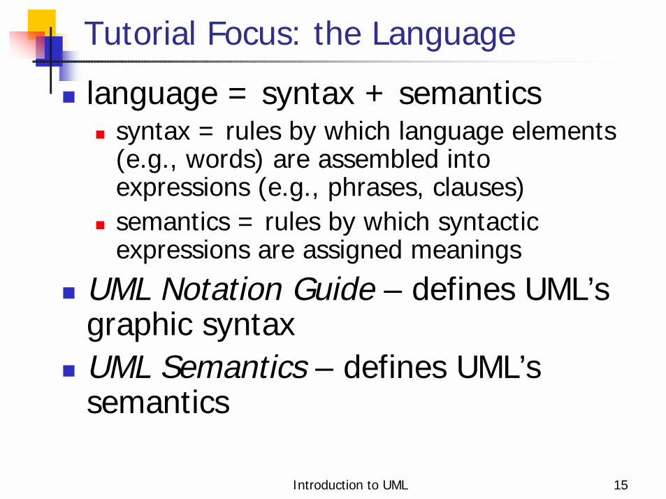
! language = syntax + semantics! syntax = rules by which language elements
(e.g., words) are assembled into expressions (e.g., phrases, clauses)
! semantics = rules by which syntactic expressions are assigned meanings
! UML Notation Guide – defines UML’sgraphic syntax
! UML Semantics – defines UML’ssemantics
Introduction to UML 16
! Building blocks! Well-formedness rules
Foundation Concepts
Introduction to UML 17
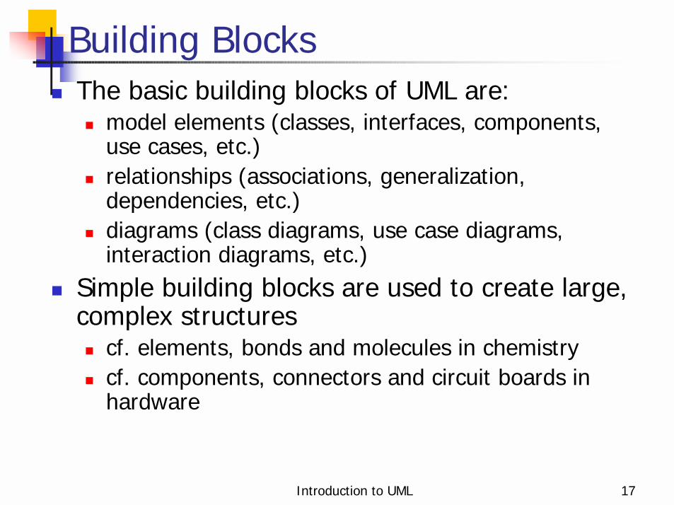
! The basic building blocks of UML are:! model elements (classes, interfaces, components,
use cases, etc.)! relationships (associations, generalization,
dependencies, etc.)! diagrams (class diagrams, use case diagrams,
interaction diagrams, etc.)! Simple building blocks are used to create large,
complex structures! cf. elements, bonds and molecules in chemistry! cf. components, connectors and circuit boards in
hardware
Building Blocks

Introduction to UML 18
Diagram: Classifier View
Element
Carbon Hydrogen
<<covalent>>
<<covalent>>C
C
C H

Introduction to UML 19
Diagram: Instance View
:Carbon :Carbon
:Hydrogen
:Hydrogen
:Hydrogen
:Hydrogen
:Hydrogen:Hydrogen
Introduction to UML 20
Well-Formedness Rules! Well-formed: indicates that a model or model
fragment adheres to all semantic and syntactic rules that apply to it.
! UML specifies rules for:! naming! scoping! visibility! integrity! execution (limited)
! However, during iterative, incremental development it is expected that models will be incomplete and inconsistent.
Introduction to UML 21
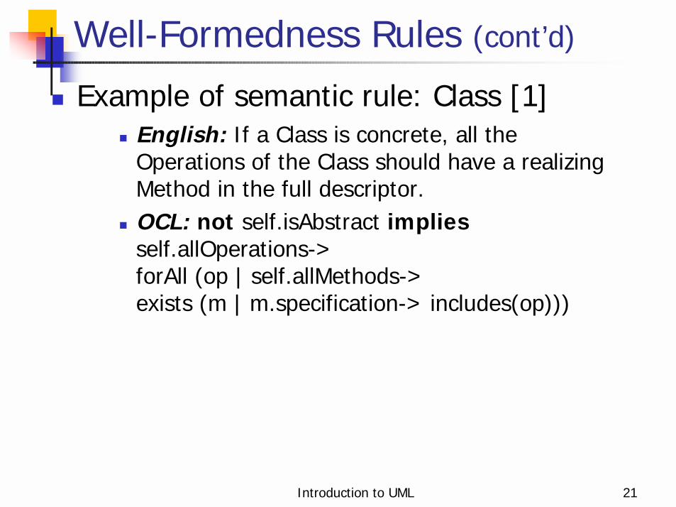
Well-Formedness Rules (cont’d)
! Example of semantic rule: Class [1]! English: If a Class is concrete, all the
Operations of the Class should have a realizing Method in the full descriptor.
! OCL: not self.isAbstract impliesself.allOperations->forAll (op | self.allMethods->exists (m | m.specification-> includes(op)))

Introduction to UML 22
Well-Formedness Rules (cont’d)
! Example of syntactic rules: Class! Basic Notation: A class is drawn as a solid-
outline rectangle with three compartments separated by horizontal lines.
! Presentation Option: Either or both of the attribute and operation compartments may be suppressed.
! Example of syntactic guideline: Class! Style Guideline: Begin class names with an
uppercase letter.

Introduction to UML 23
Unifying Concepts! classifier-instance dichotomy
! e.g., an object is an instance of a class ORa class is the classifier of an object
! specification-realization dichotomy! e.g., an interface is a specification of a
class ORa class is a realization of an interface
! analysis-time vs. design-time vs. run-time! modeling phases (“process creep”)! usage guidelines suggested, not enforced
Introduction to UML 24
Language Architecture
! Metamodel architecture! Package structure

Introduction to UML 25
Metamodel Architecture
«metaclass»Attribute
«metaclass»Class
«metaclass»Operation
«instanceOf»
<<metamodel>>UML Metamodel
Analysis ModelThe attribute fare ofthe PassengerTicketclass is an instance ofthe metaclassAttribute.
The operationissue of thePassengerTicketclass is aninstance of themetaclassOperation.
«instanceOf»«instanceOf»
«instanceOf»
<<use>>
<<use>>
Represents theUser Object layerof the 4-layermetamodelarchitecturepattern.
«metaclass»Class
<<metamodel>>MOF Meta-Metamodel
«metaclass»Operation
«metaclass»Attribute
PassengerTicket
+total()+issue()+surrender()+refund()
-issuedBy : Airline-issuingAgent : TravelAgent-fare : Currency-tax : Currency
45723990550: PassengerTicket
-issuedBy : Airline = AcmeAirlines-issuingAgent : TravelAgent = TerrificTravel-fare : Currency = 1050.00-tax : Currency = 57.56
«instanceOf»
From [Kobryn 01b].

Introduction to UML 26
UML Metamodel Layer
Foundation
Core Extension Mechanisms
Data Types
Behavioral Elements
Collaborations Use Cases State Machines
Common Behavior
Activity Graphs
Model Management
package
dependency
From [Kobryn 01b].

Introduction to UML 27
Relationships to Other Modeling Technologies
XMIFacility
UML Profilefor CORBA
UML Profilefor Telecom
Meta ObjectFacility
Metadata layer
Specificationlayer
Customizationlayer
Platformtechnologyprofiles
Domaintechnologyprofiles
UnifiedModelingLanguage
<<document>>UML XMI DTD
<<document>>UML CORBA IDL
From [Kobryn 01b].
Introduction to UML 28
Structural Modeling
! What is structural modeling?! Core concepts! Diagram tour! When to model structure! Modeling tips! Example: Interface-based design

Introduction to UML 29
What is structural modeling?
! Structural model: a view of an system that emphasizes the structure of the objects, including their classifiers, relationships, attributes and operations.

Introduction to UML 30
Construct Description Syntax class a description of a set of objects
that share the same attributes, operations, methods, relationships and semantics.
interface a named set of operations that characterize the behavior of an element.
component a modular, replaceable and significant part of a system that packages implementation and exposes a set of interfaces.
node a run-time physical object that represents a computational resource.
«interface»
Structural Modeling: Core Elements

Introduction to UML 31
Structural Modeling: Core Elements (cont’d)
Construct Description Syntax constraint¹ a semantic condition or restriction.
{constraint}
¹ An extension mechanism useful for specifying structural elements.

Introduction to UML 32
Construct Description Syntax association a relationship between two or more
classifiers that involves connections among their instances.
aggregation A special form of association that specifies a whole-part relationship between the aggregate (whole) and the component part.
generalization a taxonomic relationship between a more general and a more specific element.
dependency a relationship between two modeling elements, in which a change to one modeling element (the independent element) will affect the other modeling element (the dependent element).
Structural Modeling: Core Relationships

Introduction to UML 33
Construct Description Syntax realization a relationship between a specification
and its implementation.
Structural Modeling: Core Relationships (cont’d)

Introduction to UML 34
! Show the static structure of the model! the entities that exist (e.g., classes, interfaces,
components, nodes)! internal structure! relationship to other entities
! Do not show! temporal information
! Kinds! static structural diagrams
! class diagram! object diagram
! implementation diagrams! component diagram! deployment diagram
Structural Diagram Tour

Introduction to UML 35
Static Structural Diagrams
! Shows a graph of classifier elements connected by static relationships.
! kinds! class diagram: classifier view! object diagram: instance view

Introduction to UML 36
Classes
Fig. 3-20, UML Notation Guide
Window
display ()
size: Areavisibility: Boolean
hide ()
WindowWindow
+default-size: Rectangle#maximum-size: Rectangle
+create ()
+display ()
+size: Area = (100,100)#visibility: Boolean = true
+hide ()
-xptr: XWindow*
-attachXWindow(xwin:Xwindow*)
{abstract,author=Joe,status=tested}

Introduction to UML 37
Classes: compartments with names
Fig. 3-23, UML Notation Guide
bill no-shows
Reservation
operationsguarantee()cancel ()change (newDate: Date)
responsibilities
match to available rooms
exceptions
invalid credit card

Introduction to UML 38
Classes: method body
Fig. 3-24, UML Notation Guide
report ()
BurglarAlarm
isTripped: Boolean = false
PoliceStation
1 station
*
{ if isTrippedthen station.alert(self)}
alert (Alarm)

Introduction to UML 39
Types and Implementation Classes
Fig. 3-27, UML Notation Guide
Set«type»
addElement(Object)removeElement(Object)testElement(Object):Boolean
* elements
Object«type»
HashTableSet«implementationClass»
addElement(Object)removeElement(Object)testElement(Object):Boolean
1 body
HashTable«implementationClass»
setTableSize(Integer)
Introduction to UML 40
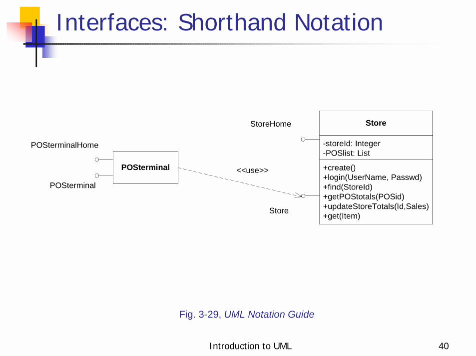
Interfaces: Shorthand Notation
Fig. 3-29, UML Notation Guide
+create()+login(UserName, Passwd)+find(StoreId)+getPOStotals(POSid)+updateStoreTotals(Id,Sales)+get(Item)
-storeId: Integer-POSlist: List
Store
POSterminal
POSterminalHome
<<use>>
StoreHome
Store
POSterminal

Introduction to UML 41
Interfaces: Longhand Notation
Fig. 3-29, UML Notation Guide
+create()+login(UserName, Passwd)+find(StoreId)+getPOStotals(POSid)+updateStoreTotals(Id,Sales)+get(Item)
-storeId: Integer-POSlist: List
Store
POSterminal
POSterminalHome
<<use>>
StoreHome
POSterminal
+getPOStotals(POSid)+updateStoreTotals(Id,Sales)+get(Item)
<<interface>>Store

Introduction to UML 42
Associations
Fig. 3-40, UML Notation Guide
Person
Manages
JobCompany
boss
worker
employeeemployer1..∗
∗
∗
0..1
Job
Account
Person
Corporation
{Xor}
salary

Introduction to UML 43
Association Ends
Fig. 3-41, UML Notation Guide
Polygon PointContains
{ordered}
3..∗1
GraphicsBundle
colortexturedensity
1
1
-bundle
+vertex

Introduction to UML 44
Fig. 3-44, UML Notation Guide
PlayerTeam
Year
Recordgoals forgoals againstwinslosses
goalkeeper∗
∗
∗
season
team
ties
Ternary Associations

Introduction to UML 45
Composition
Fig. 3-45, UML Notation Guide
Window
scrollbar [2]: Slidertitle: Headerbody: Panel
Window
scrollbar title body
Header Panel
2 1 1
Slider
111

Introduction to UML 46
Composition (cont’d)
Fig. 3-45, UML Notation Guide
scrollbar:Slider
Window
2
title:Header1
body:Panel1

Introduction to UML 47
Generalization
Fig. 3-47, UML Notation Guide
Shape
SplineEllipsePolygon
Shape
SplineEllipsePolygon
Shared Target Style
Separate Target Style
. . .
. . .

Introduction to UML 48
Generalization
Fig. 3-48, UML Notation Guide
Vehicle
WindPoweredVehicle
MotorPoweredVehicle
LandVehicle
WaterVehicle
venuevenuepower
power
SailboatTruck
{overlapping} {overlapping}

Introduction to UML 49
Dependencies
Fig. 3-50, UML Notation Guide
«friend»ClassA ClassB
ClassC
«instantiate»
«call»
ClassD
operationZ()«friend»
ClassD ClassE
«refine» ClassC combinestwo logical classes

Introduction to UML 50
Dependencies
Fig. 3-51, UML Notation Guide
Controller
DiagramElements
DomainElements
GraphicsCore
«access»
«access»
«access»«access»
«access»

Introduction to UML 51
Derived Attributes and Associations
Fig. 3-52, UML Notation Guide
Person
birthdate/age{age = currentDate - birthdate}
Company
Person
Department
WorksForDepartment
/WorksForCompany
{ Person.employer=Person.department.employer }
∗
∗∗
1
1
1employeremployer
department

Introduction to UML 52
Objects
Fig. 3-38, UML Notation Guide
trian g le : P olyg on
c en te r = (0 ,0 )ve rtic e s = ( (0 ,0 ),(4 ,0) ,(4,3 ))bo rd e rC olo r = bla c kfillCo lo r = wh ite
tria ng le : P o lyg o n
tria ng le
:P olyg on
s ch ed u le r

Introduction to UML 53
Composite objects
Fig. 3-39, UML Notation Guide
horizontalBar:ScrollBar
verticalBar:ScrollBar
awindow : Window
surface:Pane
title:TitleBar
moves
moves

Introduction to UML 54
Links
Fig. 3-46, UML Notation Guide
downhillSkiClub:Club Joe:Person
Jill:Person
Chris:Person
member
member
member
treasurer
officer
president
officer

Introduction to UML 55
Constraints and Comments
Fig. 3-17, UML Notation Guide
Me m b e r-of
C h a ir-o f
{s ub s e t}P e rs o n Co m m itte e
P e rs o n C o m pa ny
b os s
{P e rs o n. e m p loye r =P e rs o n. bo s s .e m p lo ye r}
e m p loye re m p lo ye e
0 .. 1
∗ ∗
∗
∗
∗ 0 .. 1
1
R e p re s e n tsa n in c o rpo ra te d e n tity.

Introduction to UML 56
Class Diagram Example
+getOrderStatus+setOrderStatus+getLineItems+setLineItems+getCreditApproved+setCreditApproved...
OrderBean{abstract}
LineItem{abstract}
Product
1
*
1
*
<<interface>>EntityBean
CreditCard{abstract}
Customer
PMOrder
PMLineItem
PMCreditCard
*
1
*
buyer
order
order
item
item
commodity
Adapted from Fig. 23 [EJB 2.0].
Introduction to UML 57
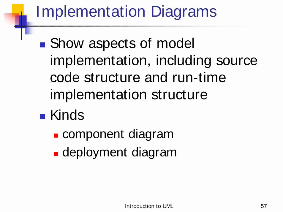
Implementation Diagrams
! Show aspects of model implementation, including source code structure and run-time implementation structure
! Kinds! component diagram! deployment diagram

Introduction to UML 58
! Shows the organizations and dependencies among software components
! Components may be! specified by classifiers (e.g.,
implementation classes)! implemented by artifacts (e.g., binary,
executable, or script files)
Component Diagram

Introduction to UML 59
Fig. 3-99, UML Notation Guide (corrected)
Components
<<Entity>>030303zak:Order
OrderHome
Order
OrderPK
<<Session>>ShoppingSession
ShoppingSessionHome
ShoppingSession
OrderInfo
<<focus>>:Order
<<auxiliary>>:OrderPK
<<auxiliary>>:OrderInfo
OrderHome
Order

Introduction to UML 60
Fig. 3-95, UML Notation Guide
Component Diagram
<<EJBEntity>>Catalog
CatalogHome
Catalog
CatalogPK
<<EJBSession>>ShoppingSession
ShoppingSessionHome
ShoppingSession
CatalogInfo
<<file>>CatalogJAR
<<focus>>Catalog
<<auxiliary>>CatalogPK
<<auxiliary>>CatalogInfo
CatalogHome
Catalog
<<EJBEntity>>ShoppingCart
ShoppingCartHome
ShoppingCart

Introduction to UML 61
Fig. 3-96, UML Notation Guide
Component Diagram with Relationships
<<ejbEntity>>Catalog
<<auxiliary>>CatalogInfo
<<focus>>Catalog
<<reside>> <<reside>>
<<auxiliary>>CatalogPK
<<reside>>
<<file>>CatalogJAR
<<implement>>

Introduction to UML 62
Deployment Diagram
! Shows the configuration of run-time processing elements and the software components, processes and objects that live on them
! Deployment diagrams may be used to show which components may run on which nodes

Introduction to UML 63
Deployment Diagram (1/2)
Fig. 3-97, UML Notation Guide
:DBServer
videoStoreServer:AppServer<<Container>>
VideoStoreApplication
:Client
<<browser>>:OpenSourceBrowser
<<Session>>ShoppingSession
<<Focus>>ShoppingSession
<<Entity>>Catalog
<<Focus>>Catalog
<<Entity>>ShoppingCart
<<Focus>>ShoppingCart
<<database>>:VideoStoreDB
Introduction to UML 64
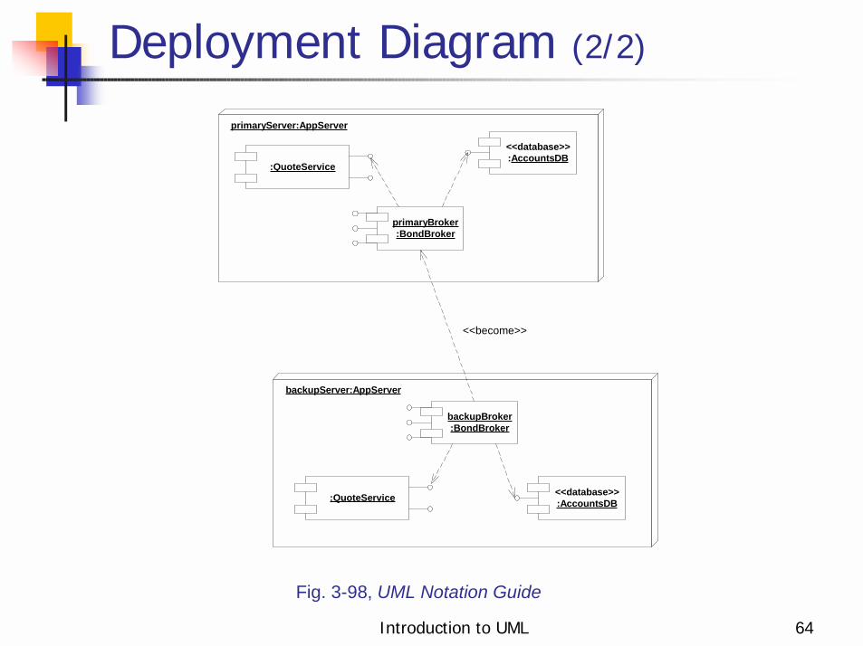
Deployment Diagram (2/2)
Fig. 3-98, UML Notation Guide
backupServer:AppServer
backupBroker:BondBroker
:QuoteService <<database>>:AccountsDB
primaryServer:AppServer
primaryBroker:BondBroker
:QuoteService
<<database>>:AccountsDB
<<become>>

Introduction to UML 65
When to model structure! Adopt an opportunistic top-down+bottom-up approach
to modeling structure! Specify the top-level structure using “architecturally significant”
classifiers and model management constructs (packages, models, subsystems; see Tutorial 3)
! Specify lower-level structure as you discover detail re classifiers and relationships
! If you understand your domain well you can frequently start with structural modeling; otherwise! If you start with use case modeling (as with a use-case driven
method) make sure that your structural model is consistent with your use cases
! If you start with role modeling (as with a collaboration-driven method) make sure that your structural model is consistent with your collaborations

Introduction to UML 66
Structural Modeling Tips
! Define a “skeleton” (or “backbone”) that can be extended and refined as you learn more about your domain.
! Focus on using basic constructs well; add advanced constructs and/or notation only as required.
! Defer implementation concerns until late in the modeling process.
! Structural diagrams should! emphasize a particular aspect of the structural model! contain classifiers at the same level of abstraction
! Large numbers of classifiers should be organized into packages (see Lecture 3)

Introduction to UML 67
Example: Point-of-Sale
! The following example shows how UML can model the interfaces for a Point of Sale application originally specified in CORBA IDL. From [Kobryn 01b].

Introduction to UML 68
Point-of-Sale Example
module POS
{
typedef long POSId;
typedef string Barcode;
interface InputMedia
{
typedef string OperatorCmd;
void BarcodeInput(in Barcode Item);
void KeypadInput(in OperatorCmd Cmd);
};
interface OutputMedia
{...};
interface POSTerminal
{...};};
...Ch. 26, CORBA Fundamentals and Programming (2nd ed.), [Siegel 00]

Introduction to UML 69
From [Kobryn 2001b]
Point_Of_Sale
POSterminal
+outputText()
«CORBAInterface»IOutputMedia
InputMedia +initialization()+barcodeInput()+keypadInput()
-POSref : POSterminal
«CORBAInterface»IInputMedia
OutputMedia
Store
+initialization()+findPrice()
-depotRef :-taxRef : Tax-storeMarkup : float-storeId : Integer
«CORBAInterface»IStoreAccess
+initialization()+calculateTax()+findTaxablePrice()
-rate : float
«CORBAInterface»ITax
+initialization()+login()+printPOSsalesSummary()+printStoreSalesSummary()+setItemQuantity()+sendBarcode()+endSale()
-storeRef : Store-storeAccessRef : StoreAccess-outputMediaRef : OutputMedia-taxRef : Tax-POSid : Integer-itemBarcode : Integer-itemQuantity : Integer-itemInfo : ItemInfo-itemPrice : Currency-itemTaxPrice : Currency-itemExtension : Currency-saleSubtotal : Currency-taxableSubtotal : Currency-saleTotal : Currency-saleTax : Currency-POSlist : List
«CORBAInterface»IPOSterminal
+initialization()+login()+getPOStotals()+updateStoreTotals()+getTotals()+getStoreId()
-totals : Totals-POSlist : List
«CORBAInterface»IStore
StoreAccess
Tax
longhand notationfor interface
class
+intialization()+findItemInfo()
«CORBAInterface»IDepot
Depot
POS Class Diagram

Introduction to UML 70
POS Deployment Diagram
:POSterminalIPOSterminal
:OutputMediaIOutputMedia
:StoreIStore
:TaxITax
:StoreAccessIStoreAccess
:InputMediaIInputMedia
:StoreServerstation3:POSStation
:POSstation
<<network>>:LocalAreaNetwork
<<ethernet>> <<ethernet>>
:DBServer :POSstation
<<ethernet>> <<ethernet>><<ethernet>>
node component.shorthand("lollipop")notation forinterface.
:DepotIDepot
From [Kobryn 2001b]

Introduction to UML 71
Model Fragment from POS Example
From [Kobryn 2001b]
+initialization()+calculateTax()+findTaxablePrice()
-rate : float
«CORBAInterface»ITax
Tax

Introduction to UML 72
XML Generated by XMI Facility
From [Kobryn 2001b]
<XMI xmi.version = '1.1' xmlns:UML='//org.omg/UML/1.3' ...>
<XMI.header>
<XMI.metamodel xmi.name = 'UML' xmi.version = '1.3'/>
</XMI.header>
<XMI.content>
<!-- POS_Example_R2 [Model] -->
<UML:Model xmi.id = 'G.0'
name = 'POS_Example_R2' visibility = 'public' isSpecification = 'false'
isRoot = 'false' isLeaf = 'false' isAbstract = 'false' >
<UML:Namespace.ownedElement>
<!-- POS_Example_R2::Tax [Class] -->
<UML:Class xmi.id = 'S.1'
name = 'Tax' visibility = 'public' isSpecification = 'false'
isRoot = 'true' isLeaf = 'true' isAbstract = 'false'
isActive = 'false'
namespace = 'G.0' clientDependency = 'G.1' />
...

Introduction to UML 73
Use Case Modeling
! What is use case modeling?! Core concepts! Diagram tour! When to model use cases! Modeling tips! Example: Online HR System

Introduction to UML 74
What is use case modeling?
! use case model: a view of a system that emphasizes the behavior as it appears to outside users. A use case model partitions system functionality into transactions (‘use cases’) that are meaningful to users (‘actors’).

Introduction to UML 75
Use Cases: Core Elements
Construct Description Syntax use case A sequence of actions, including
variants, that a system (or other entity) can perform, interacting with actors of the system.
actor A coherent set of roles that users of use cases play when interacting with these use cases.
system boundary
Represents the boundary between the physical system and the actors who interact with the physical system.
UseCaseName
ActorName

Introduction to UML 76
Construct Description Syntax association The participation of an actor in a use
case. i.e., instance of an actor and instances of a use case communicate with each other.
generalization A taxonomic relationship between a more general use case and a more specific use case.
include a relationship from a base use case to an inclusion use case, specifying how the behavior for the base use case contains the behavior defined for the inclusion use case. The base use case depends on the inclusion use case. Compare: extend.
Use Cases: Core Relationships
<<include>>
Introduction to UML 77
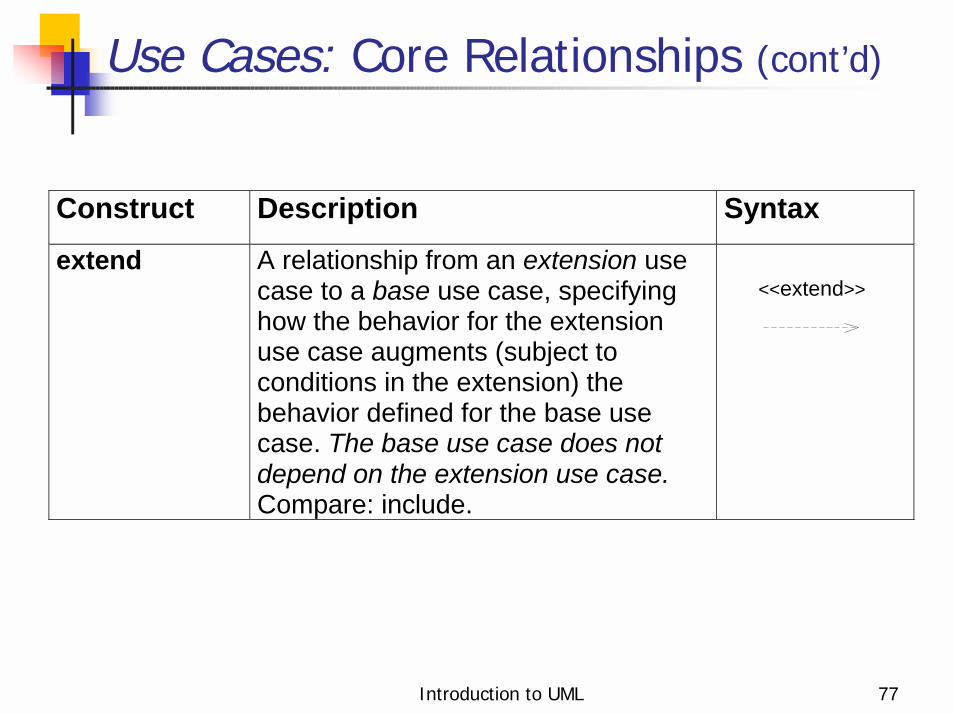
Construct Description Syntax extend A relationship from an extension use
case to a base use case, specifying how the behavior for the extension use case augments (subject to conditions in the extension) the behavior defined for the base use case. The base use case does not depend on the extension use case. Compare: include.
Use Cases: Core Relationships (cont’d)
<<extend>>

Introduction to UML 78
! Shows use cases, actors and their relationships
! Use case internals can be specified by text and/or interaction diagrams (see Lecture 2)
! Kinds! use case diagram! use case description
Use Case Diagram Tour

Introduction to UML 79
Fig. 3-53, UML Notation Guide
Cus tomer
Supe rviso r
Sales pe rso nPlace
Establis hc re dit
Che c k
Telephone Catalog
Fill orders
Shipping Cle rk
s tatus
orde r
Use Case Diagram
Introduction to UML 80
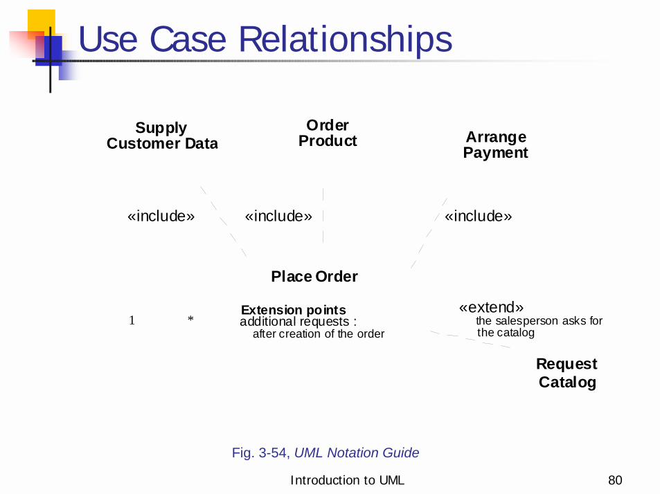
Fig. 3-54, UML Notation Guide
Use Case Relationships
additional requests :
OrderProduct
Supply Arrange
«include»«include»«include»
RequestCatalog
«extend»Extension points
PaymentCustomer Data
after creation of the order
Place Order
1 * the salesperson asks forthe catalog

Introduction to UML 81
Fig. 3-55, UML Notation Guide
Actor Relationships
EstablishCredit
PlaceOrder
Salesperson
Supervisor
1 *
1 *

Introduction to UML 82
Use Case Description: Change Flight
■Actors: traveler, client account db, airline reservation system■Preconditions:
• Traveler has logged on to the system and selected ‘change flight itinerary’ option
■Basic course• System retrieves traveler’s account and flight itinerary from client account database• System asks traveler to select itinerary segment she wants to change; traveler selects itinerary segment.• System asks traveler for new departure and destination information; traveler provides information.• If flights are available then• …• System displays transaction summary.
■Alternative courses• If no flights are available then …

Introduction to UML 83
When to model use cases! Model user requirements with use cases.! Model test scenarios with use cases.! If you are using a use-case driven
method! start with use cases and derive your
structural and behavioral models from it.! If you are not using a use-case driven
method! make sure that your use cases are consistent
with your structural and behavioral models.

Introduction to UML 84
Use Case Modeling Tips
! Make sure that each use case describes a significant chunk of system usage that is understandable by both domain experts and programmers
! When defining use cases in text, use nouns and verbs accurately and consistently to help derive objects and messages for interaction diagrams (see Lecture 2)
! Factor out common usages that are required by multiple use cases! If the usage is required use «include»! If the base use case is complete and the usage may be optional,
consider use «extend»! A use case diagram should
! contain only use cases at the same level of abstraction! include only actors who are required
! Large numbers of use cases should be organized into packages (see Lecture 3)

Introduction to UML 85
Example: Online HR System
Online HR System
LocateEmployees
UpdateEmployee
Profile
Update Benefits
Access TravelSystem
Access PayRecords
Employee
Manager
Healthcare Plan System
{if currentMonth = Oct.}
{readOnly}
Insurance Plan System

Introduction to UML 86
Online HR System: Use Case Relationships
Update MedicalPlan
Update DentalPlan
Update Benefits______________Extension pointsbenefit options:
after required enrollments
UpdateInsurance Plan
Employee
<<include>> <<include>> <<include>>
ElectReimbursementfor Healthcare
Elect StockPurchase
<<extend>>employee requestsstock purchase option
<<extend>>employee requestsreimbursement option
extensioncondition
extension pointname andlocation

Introduction to UML 87
Online HR System: Update Benefits Use Case
■Actors: employee, employee account db, healthcare plan system, insurance plan system■Preconditions:
• Employee has logged on to the system and selected ‘update benefits’ option
■Basic course• System retrieves employee account from employee account db• System asks employee to select medical plan type; include Update Medical Plan.• System asks employee to select dental plan type; include Update Dental Plan.• …
■Alternative courses• If health plan is not available in the employee’s area the employee is informed and asked to select another plan...

Introduction to UML 88
Wrap Up! Ideas to take away! Preview of next tutorial! References! Further info

Introduction to UML 89
! UML is effective for modeling large, complex software systems
! It is simple to learn for most developers, but provides advanced features for expert analysts, designers and architects
! It can specify systems in an implementation-independent manner
! 10-20% of the constructs are used 80-90% of the time
! Structural modeling specifies a skeleton that can be refined and extended with additional structure and behavior
! Use case modeling specifies the functional requirements of system in an object-oriented manner
Ideas to Take Away

Introduction to UML 90
Preview - Next Tutorial
! Behavioral Modeling with UML! Behavioral modeling overview! Interactions! Collaborations! Statecharts! Activity graphs

Introduction to UML 91
References
! [UML 1.4] OMG UML Specification v. 1.4, UML Revision Task Force, OMG doc# ad/01-02-13.
! [Kobryn 01a] C. Kobryn, “UML 2.0 Roadmap: Fast Track or Detours?,” Software Development, April 2001.
! [Kobryn 01b] C. Kobryn, “Modeling Distributed Applications with UML,” Part IV: Chapter 1 in [Siegel 01] Quick CORBA 3, Wiley, 2001.
! [Kobryn 00] “Modeling CORBA Applications with UML,” chapter 21 in [Siegel 00] CORBA 3 Fundamentals and Programming (2nd ed.), Wiley, 2000.
! [Kobryn 99] UML 2001: A Standardization Odyssey, Communications of the ACM, Oct. 1999.
! [EJB 2.0] Enterprise JavaBeans Specification v. 2.0, Sun Microsystems, March 31, 2000.
Introduction to UML 92
! Web: ! UML 1.4 RTF: www.celigent.com/omg/umlrtf! OMG UML Tutorials:
www.celigent.com/omg/umlrtf/tutorials.htm! UML 2.0 Working Group:
www.celigent.com/omg/adptf/wgs/uml2wg.htm! OMG UML Resources: www.omg.org/uml/
! Email! [email protected]! [email protected]
! Conferences & workshops! UML World 2001, New York, June 11-14, 2001! UML 2001, Toronto, Canada, Oct. 1-5, 2001! OMG UML Workshop 2001, San Francisco, Dec. 3-6, 2001! UML Forum/Tokyo 2002, Tokyo, Japan, April 2002.
Further Info


![[UML] UML, Metodologias e Ferramentas CASE us](https://static.cupdf.com/doc/110x72/5571f34149795947648dbd59/uml-uml-metodologias-e-ferramentas-case-us.jpg)