1
ME 5286 Robotics Labs, Spring 2020
Lab 1: Hello Cobot World
Duration: 2 Weeks 1/27/2020 – 2/7/2020)
Introduction to Robotics:
Welcome to ME 5286: Robotics! The lab modules will take you through the core principles and
applications of collaborative robots (cobots) which are now commonly used in industry. You will
be working with the “UR5”, a popular model of cobot manufactured by the company “Universal
Robots”. To learn more about the UR5, you can visit this link: https://www.universal-
robots.com/products/ur5-robot/. In this first lab, you will learn how to operate the UR5 safely
and effectively. There are many quirks associated with operating the UR5 (or any robot), but we
hope to alleviate some stress by walking you through the basics and providing tips and tricks
when necessary. However, we will not be providing you with all the answers, so if you want to
be successful in this lab, we do expect that you read the manual, refresh your Python skills, and
develop your own methods for completing the required tasks.
_____________________________________________________________________________________________________________________
Objective:
Familiarize yourself with the UR5 robot and PolyScope, RoboDK, and the RoboDK Python
API programming environments. For tasks 1-3, you will move the robot through specified
waypoints in joint and Cartesian space using all three programming methods. In task 4, you
will command the UR5 to trace a virtual cube and thus “explore the workspace”. Task 5 does not
require any robot commands, but you will analyze data that we will provide from an impact test.
On the ME5286 Robotics site, navigate to Robot Lab → Resources to find documentation on
useful RoboDK API functions, a guide to the basics of RoboDK and a Python tutorial.
_____________________________________________________________________________________________________________________
Important Notes:
Safety:
At least two people must be present in the lab when operating the UR5 robot. Upload a
selfie of you, your partner, and the robot to the Canvas submission link before starting any
lab.
Read all warnings and cautions in the manual. You can start with the pages listed in the Prelab.
Saving Files:
One of the most unfortunate mistakes students make in this course is losing their code. Can you
imagine putting in many hours of work, just to have it all disappear, or to submit the wrong file?
DON’T LET THIS BE YOU! Follow the suggested tips listed below.

2
Saving Procedural Tips:
Before your lab period, when preparing your RoboDK files on your PC or Mac, save
them to your computer, a flash drive, and/or the cloud (Google Drive) (which you should
ALWAYS do for any program you are working on). Use the following (suggested)
format:
o ME5286_Lab#_Task#_LastName_FirstName_v#
When working on your laptop or in the lab, continuously save files with updated version
numbers. Then, if you lose a file, you don’t have to restart the whole project. (Τhis is
most relevant when working with Python API).
A flash drive is NOT permanent storage. These can be easily lost or corrupted. Always
back up your files to the cloud and to your laptop after working in the lab. You will
however, need to save files to a flash drive so they can be transferred to the robot.
In the lab - once you are done with all your tasks for the day:
1) Save all your programs to permanent storage
2) Remove all* your programs from the Robot’s computer.
*Failure to remove your programs from the robot’s computer will result in a loss of points*
Save the programs you plan to submit with the following format:
ME5286_Lab#_Task#_LastName_FirstName
_____________________________________________________________________________________________________________________
Terms Defined:
Teach Pendant
This is the touch screen tablet that you will use to control the
robot. It is home of the PolyScope Graphical User Interface
(GUI). (Figure 1)
PolyScope
You use PolyScope when you create a program directly on the
Teach Pendant to simulate or control the robot.
RoboDK GUI
RoboDK is a robot simulation program that you will use on the
lab computers and on your laptop to generate instructions that
will move the robot in a simulated environment and in real time.
It has a built-in GUI that allows you to set up targets. (Figure 2)
RoboDK Python API
Alternatively, you can create instructions in RoboDK by writing
a Python script. You can run the script in RoboDK to check your
work.
URScript
URScript is the language understood by the UR5. A post
processor is used to convert RoboDK Python API to URScript.

3
Waypoints
Locations in the robot workspace that the end effector moves
through. ‘Target’ is the term used by RoboDK for a ‘waypoint’
or ‘pose’.
Pose
A pose is essentially a waypoint. These are defined by either the
robot joint positions, or the x-y-z position and 3 orientation
angles of the end effector. A more detailed description can be
found in section 12.2 starting on page II-36 of the robot manual.
Please note that Universal Robots uses the roll-pitch-yaw angles
convention described by the RPY-rotation matrix (X, Y’, Z”
rotation) given by: Rrpy(γ, β, α) = RZ(α) • RY(β) • RX(γ).
Compare this with the textbook (Sect. 2.5.2 in the 2006 edition).
Joint Space
In joint space, you define the angle for each individual joint,
rather than the pose of the end effector (the forward kinematic
equations take you from the set of joint angles to the pose of the
end effector).
Cartesian Space
In Cartesian space, you define the location and orientation of the
end effector, and the robot performs the inverse kinematic
calculations to determine how each joint must be oriented (there
may be many solutions – not all are great).
Tool Center Point (TCP)
The Tool Center Point is the center location of the tool relative
to the end effector of the UR5 (the tool can be the gripper, a
probe, or any other addition to the end of the robot). Universal
Robots calls the “Connecting Flange” the end effector, which is
where the tool connects to the robot. Text books and other
manufacturers call the tool the “end effector”. Please be careful
with terminology.
Freedrive
The “freedrive” mode is useful when you want to move the robot
arm into a position quickly without knowing the pose. To
freedrive the arm, hold the button on the back of the Teach
Pendant while physically moving the arm into a position.
Release the button to lock the position in place. (see II-40 in the
UR5 manuals)
Home Position
For the UR5, defined by the joint angles: [0 -90 0 -90 0 0]. It is
advised that you create programs where the robot starts and
ends in the home position. The robot is in the home position in
Figure 2 and in Figure 18.
4
Figure 1: This is the Teach Pendant. Make sure either you or your partner is always prepared to press the
red STOP button when the robot is turned on.
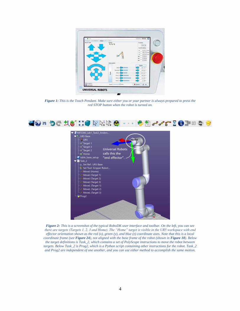
Figure 2: This is a screenshot of the typical RoboDK user interface and toolbar. On the left, you can see
there are targets (Targets 1, 2, 3 and Home). The “Home” target is visible in the UR5 workspace with end
effector orientation shown as the red (x), green (y), and blue (z) coordinate axes. Note that this is a local
coordinate frame (see Figure 24), not aligned with the base frame of the robot (shown in Figure 18). Below
the target definitions is Task_2, which contains a set of PolyScope instructions to move the robot between
targets. Below Task_2 is Prog2, which is a Python script containing other instructions for the robot. Task_2
and Prog2 are independent of one another, and you can use either method to accomplish the same motion.

5
Other Helpful Tips Before Starting:
The UR5 LOVES to crash into itself. It can be hard to tell from watching your simulation in
RoboDK to know if this will happen when you upload your code to the robot. One of the most
useful tools in RoboDK is the button shown in Figure 3 (shown here in two potential states)
which can be found in the RoboDK toolbar.
A B
Figure 3: The button that looks like a hazard symbol indicates whether RoboDK will check for collisions
during your simulation. Make sure it shows the green check mark to do so (B).
If it shows a red x (Figure 3-A), then RoboDK will not warn you if your robot crashes into itself
or the table. Click this button to show the green check (Figure 3-B), and RoboDK will halt the
program as soon as the robot arm hits something.
Another technique you will regret not knowing later in some of the lab modules is changing the
robot’s configuration in RoboDK. When you input the desired pose in Cartesian space, RoboDK
will select one of many solutions to achieve this pose. Most of these solutions are not optimal,
but RoboDK doesn’t know which to choose. You can select the configuration yourself by
clicking the target and pressing F3 (modify target), then selecting the “Change config.” box.
Click on the desired configuration and press ok. You will notice that the Robot joints have been
updated in the target settings. These will only be saved if you select “Keep joint values” instead
of “Keep Cartesian position”. It won’t matter that you have redefined your pose using joint
values, because you originally defined it using the XYZ-RXRYRZ values. This is shown in
Figure 4. Symbols from the configuration editor box are defined in Table 1.
See the course page (Robot Lab >> Resources) for additional tips that will help you as you move
through the lab sequence. You might even discover some yourselves. 😊

6
A: Elbow Up B: Elbow Down
Figure 4: RoboDK interface showing the configuration editor. In A, an “elbow up” configuration was
selected without any issues, but in B, an “elbow down” configuration was selected so the robot arm ran into
the table. In both A and B, the end effector is in the same pose.
Table 1: Key definitions corresponding to Figure 4. You don’t need to remember these definitions, it’s just good to know where
they come from.
F/R Front v. Rear – relates to how the base of the robot faces the target.
U/D Elbow Up v. Elbow Down – MOST IMPORTANT, relates to the “elbow” position
F/N Flip v. Non-flip – relates to how joint 5 moves when it reaches the pose
id There are 8 possible configuration combos (combinations of F/R, U/D, and F/N) – the
config. id differentiates between these combinations.

7
Prelab:
Read the UR5 lab manual and understand the following:
o Read the section on Risk assessments pp. I-1 – I-11 of the UR5 manual, and
Collaborative robot safety standards: ISO/TS 15066, ISO 10218-2 (details on
course website).
o There are small differences between Robot 1 and Robot 2, which is why we
provide two versions of the manual. For each of the labs, be sure to stick with the
same robot. Do not switch robots in the middle of the lab. Results may not be
consistent.
o We also provide the manual for the URScript Programming Language.
Install RoboDK (see Appendix for details)
o Understand the End User License Agreement (EULA) when installing RoboDK
o See the Announcements page on Canvas to understand how to set up the license
for your use of RoboDK in class. _____________________________________________________________________________________________________________________
Lab Procedure:
The first part of the lab (Tasks 1-3) will consist of moving the robot through 3 different poses in
both Cartesian and joint space using PolyScope, RoboDK, and RoboDK Python API.
The poses that you will be moving through are as follows:
X (mm) Y (mm) Z (mm) RX (rad) RY (rad) RZ (rad)
Pose 1 -575 -350 300 2.10 1.11 0.63
Pose 2 -240 -445 650 1.57 -1.57 -1.57
Pose 3 400 -400 200 2.79 -0.16 0
In the second part of the lab (Task 4), you will move the UR5 end effector in a “cube” to explore
the workspace. For Task 5, you will be provided data from a previously conducted experiment
and asked to analyze the results.
Remember to save multiple versions of your files as you work!
_____________________________________________________________________________________________________________________

8
Task 1:
Move the robot through a set of poses in both Cartesian and joint space using PolyScope.
Task Steps
1) Press the power button (NOT the E-STOP button) on the Teach Pendant to turn on
the UR5. Press “Go to initialization screen” when prompted (Figure 5). You will
need to then turn the robot “on” at the new screen (Figure 6), and press “start” before
the robot will move.
Figure 5: This prompt will appear when you first turn on the Teach Pendant. Press “go to initialization screen”.
Figure 6: Initialization screen. Note that the current payload is zero, meaning there is nothing attached to
the end effector.

9
2) On the “Initialize Robot” screen (Figure 6), navigate to “Configure TCP”. Ensure the
TCP offset parameter of the robot is set to the correct value of (0,0,0) and that the
payload reads 0.0. This is also outlined in the Appendix. When done, click on “EXIT”
(lower right of screen) to return to the “Initialize Robot” screen, then click “OK”
(lower right of screen) to return to the “PolyScope Robot User Interface”.
3) Press “Program Robot” on the “PolyScope Robot User Interface” page (Figure 7).
Figure 7: “PolyScope Robot User Interface” screen.
4) Press “Empty Program” on the “New Program” page (Figure 8).
Figure 8: “New Program” screen.

10
5) Navigate to the “Structure” tab, and under the “Basic” tab, press “Move” (Figure 9).
Note that on many screens, you will see two labels at the very top marked “Gripper”
and “Active Drive”. These may hide the text underneath. This menu isn’t needed for
this first lab since we don’t use the gripper, but it will be used in following lab
modules.
Figure 9: The “Structure” tab is located within the “Program” tab. Press “Move” under the “Basic” tab.
6) On the left, there is a command tree that displays the Robot Program. Click on
“Waypoint” in the Robot Program so that it is highlighted. Navigate to the command
tab and then press “Set this Waypoint” (Figure 10a). When that is done, you can
continue to add and modify waypoints as needed. (Figure 10b).
Figure 10a: On this screen, you can set and change the position of each waypoint.

11
Figure 10b: After setting a waypoint, “Change this Waypoint” will replace “Set this Waypoint” on the
screen. This screen is also where you can rename your waypoints if you wish. This screenshot shows a
waypoint named “A”.
7) You should now be at the “Move” page (Figure 11). You can set the waypoint by
changing the TCP position on the right. Make sure you are in the robot BASE
coordinate frame (not VIEW or anything else). Move the robot to Pose 1 (from Page
7) and then press okay to move on.
Figure 11: This is the “Move” tab that is used to set waypoints and move the robot. Only pay attention to the
X, Y, Z, RX, RY, and RZ shown in this figure. Your joint values and the image of the robot will correspond to
Pose 1, not what is shown in this figure. The directions associated with the Move Tool arrows have been
added by us and are not shown in the Move Tool screen.
12
8) To add Pose 2 and Pose 3, highlight the “Robot Program” in the command tree of
Figure 10 by clicking on it. Then, repeat steps 5-8 for each pose.
9) When you have defined all your waypoints and they have small green circles next to
them in the Robot Program, click on the “Graphics” tab next to the “Structure” tab.
Then, in the bottom left corner of the screen, select the “Simulation” bubble. Press
“Play” at the bottom of the screen and verify that the robot is doing what you expect
it to do. Press the “Stop” button when satisfied.
10) In the same “Graphics” tab, select the “Real Robot” bubble below the simulation
bubble and then press “Play” to watch the robot perform its task in real life.
11) Press “MoveJ” in the Robot Program and change the “MoveJ” to “MoveL” for all
waypoints by navigating to the command tab and selecting the drop down that defines
the movement type. Repeat steps 9 and 10. Note: If you began your program at the
“Home” position, you will not be able to perform a linear movement to Pose 1 (due to
a singularity along the way). Instead, perform a joint movement to Pose 1, then add
an additional linear movement to Pose 1 at the end of the program so you complete
the path shown in Figure 16.
If this is your task for the day, make sure your work is saved and shut down the robot. To shut
down the robot, you can just press the green power button on the front of the Teach Pendant.
CONGRATS! You are now an “expert” at using PolyScope. This will always be available to
you as a method for driving the robot, though you will likely find the next two methods
more versatile.
_____________________________________________________________________________________________________________________
Task 2:
Move the robot through a set of poses in both the Cartesian and joint space using RoboDK.
Note: For this task and the following task, you will encounter times when the robot runs into
itself, where the elbow of the robot runs into the table, and where you run through a singularity
and the robot stops due to singularities. This is normal and part of the learning process with
robotic arms. If you encounter these problems, stop the program, freedrive the robot into a new
configuration, and try again (You can freedrive the robot by pressing the button on the back of
the teach pendant). Through this process you will get better at understanding the robot’s
limitations and predicting which configurations will give you successful solutions.
Task Steps
1) Open RoboDK.
2) Download and open "ur5_and_table_and_gripper.rdk" from the course website and
save the work station as “ME5286_Lab1_Task1_[last name]_[first name].rdk”.
Update this file with version numbers as you move through the program. Note that
this file can still be used even though the gripper will not actually be used for this lab.

13
3) Right click on the UR5 and select “options”. Make sure that the tool frame entries are
all 0.0.
4) Select the target button shown in Figure 12.
Figure 12: This is the target button. It can be found in the RoboDK toolbar.
5) Press “F3” or right click and select “options” and assign Pose 1 for Target 1 as shown
in Figure 13.
Figure 13: Select the target you wish to edit in the command tree and press “F3” to open the options menu
shown here. Select “Keep Cartesian Position” instead of “Keep Joint Values” shown here.
6) Repeat steps 4 and 5 for Pose 2 and Pose 3.
7) With the three targets defined, the next step is to create a program to move between
the three targets. Press the “program” button (Figure 14).

14
Figure 14: This is the “Program” button. It can be found in the RoboDK toolbar.
8) Add a joint space movement by pressing the button shown in Figure 15. Right click
and set the target link to Target 1.
Figure 15: This is the “joint movement” button. It can be found in the RoboDK toolbar.
9) Repeat step 8 for Target 2 and Target 3.
10) Right click on “Prog 1” in the command tree and check “Run”. Verify that your path
matches that of the robot path in Figure 16. The target frame’s (i.e. the tool
coordinate frame) x-axis is shown as red, the y-axis as green, and the z-axis as blue.
MoveJ MoveL
Figure 16: This is what your robot paths should look like for the joint movements (left) and linear movements
(right). Note that you may wish to start and end in the home position (proper practice and highly
recommended).
11) If the path of the robot is what is expected, right click on “Prog1” and press “Run on
Robot”. You will first need to make sure the robot is connected to the computer by
following the directions in the Appendix of this document.
15
12) Next, we will look at moving the robot through Cartesian space instead of through
joint space. Right click on the “Move J” items in the command tree and select
“MoveL”. Repeat steps 10 and 11.
_____________________________________________________________________________________________________________________
Task 3:
Move the robot through a set of poses in both Cartesian and joint space using the Python API
within RoboDK. More information on this can be found at this link: https://robodk.com/offline-
programming
Task Steps
1) Open RoboDK
2) Open the "ur5_and_table_and_gripper.rdk" file from Task 2.
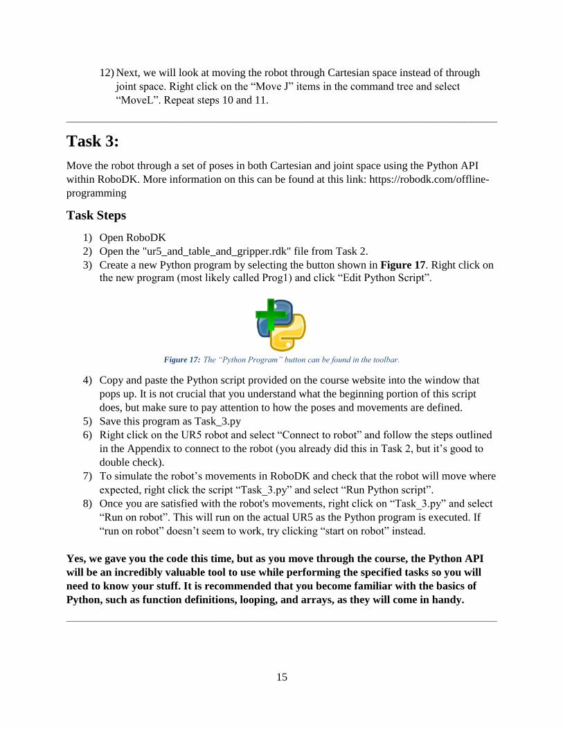
3) Create a new Python program by selecting the button shown in Figure 17. Right click on
the new program (most likely called Prog1) and click “Edit Python Script”.
Figure 17: The “Python Program” button can be found in the toolbar.
4) Copy and paste the Python script provided on the course website into the window that
pops up. It is not crucial that you understand what the beginning portion of this script
does, but make sure to pay attention to how the poses and movements are defined.
5) Save this program as Task_3.py
6) Right click on the UR5 robot and select “Connect to robot” and follow the steps outlined
in the Appendix to connect to the robot (you already did this in Task 2, but it’s good to
double check).
7) To simulate the robot’s movements in RoboDK and check that the robot will move where
expected, right click the script “Task_3.py” and select “Run Python script”.
8) Once you are satisfied with the robot's movements, right click on “Task_3.py” and select
“Run on robot”. This will run on the actual UR5 as the Python program is executed. If
“run on robot” doesn’t seem to work, try clicking “start on robot” instead.
Yes, we gave you the code this time, but as you move through the course, the Python API
will be an incredibly valuable tool to use while performing the specified tasks so you will
need to know your stuff. It is recommended that you become familiar with the basics of
Python, such as function definitions, looping, and arrays, as they will come in handy.
_____________________________________________________________________________________________________________________

16
Task 4:
Create a program that has the end effector trace the edges of a virtual rectangular “prism”. You
will be tracing two rectangular prisms for this task. The first prism should aim to maximize the
side lengths in the y-direction while the second prism should maximize length in the z-direction.
While tracing the prism edges, the orientation of the gripper should remain the same and only the
(x,y,z) portion of the pose should change. Using your software of choice (i.e. RoboDK,
PolyScope), create a program which defines eight vertices and traces a rectangular prism
between those vertices. You should develop most of this program before you come to your lab
session to ensure that you are able to finish this task on time.
Note: Your prism can be skinny but must have some width. This isn’t an optimization
problem; you don’t need to spend time creating a formula to maximize the side lengths. The
goal of this task is for you to become familiar with the robot workspace, just try to make the side
lengths as large as you can (for the direction you are focused on) without spending too much
time. The base coordinate frame is shown in Figure 18.
Figure 18: In this image, the UR5 is in the “home” position and the base frame of the robot is indicated with
red coordinate axes.
_____________________________________________________________________________________________________________________

17
Task 5:
In this task, the robot is equipped with an aluminum semi-cylinder as its end effector as seen in
Figure 19. Another semi-cylinder is attached via four load cells to two t-slot extrusions mounted
to the table. The robot will collide with this semi-cylinder, and the force will be recorded. The
purpose of this task is for you to examine what happens when the cobot hits an unexpected
“wall”.
Note: You are not conducting any experiment for this task. As mentioned in class, the
experiment has already been completed by the TAs and the data will be provided for you to
analyze.
Figure 19: Collision experiment setup.
Although you are not conducting the experiment, the steps are outlined below for your reference
so that you can understand how the experiment was performed. This will help you with your
analysis.
Task Steps
1. Prepare the Python code in order to configure the robot as shown in Figure 19. The two
aluminum semi-cylinders should be perpendicular to each other. The robot should be
positioned around [X= 300, Y= -420, Z=200].
2. Have the robot move along a straight line (using MoveL) to a point beyond the collision
fixture. This allows the robot to fully collide with the fixture during which the force will
be recorded.

18
3. BEFORE running your code on the robot, run your code offline on RoboDK. This allows
you to ensure that the robot is doing what you expected. This is good practice and should
be done for all the laboratory modules.
4. Run the following experiment three times at each speed setting in a range from 0 to 1.2
m/s. To do this, move the end effector so that it collides with the collision fixture at speed
increments of 5% of the max speed (1.2 m/s) between 0 and 0.6 m/s and in 10%
increments between 0.6 and 1.2 m/s. Be sure to record the data using the PuTTY
software.
(see the Miscellaneous Instructions and Troubleshooting Guide on the course web site’s
Lab Assignments page for how to use PuTTY).
For reference, the collision speeds that were run are; 0.06, 0.12, 0.18, 0.24, 0.30, 0.36, 0.42, 0.48,
0.54, 0.60, 0.72, 0.84, 0.96, 1.08, 1.29 m/s.
You will be given the results of this experiment which can be downloaded from the course
webpage. You will be analyzing these results as described in the deliverables section.
_____________________________________________________________________________________________________________________
Deliverables:
A single zip file named [last_name]_[first name]_helloworld.zip containing all robot
files (RoboDK, Python, Universal Robot Projects) uploaded to Canvas.
A hard copy turned in during class and a PDF file uploaded to Canvas, in memo
format, which includes:
Task 1-3:
1) Describe the difference between joint and Cartesian space and how that affected the
motion of the robot.
2) Describe the limitations of the robot’s workspace based upon the mounting location
of the robot on the table.
3) Show the usable workspace of the robot. Use a program (Matlab, Excel, etc.) to plot
the workspaces. This can either be a 3D view or multiple 2D views.
4) What are the two safety planes? And how did you determine where they were?
5) Is the robot elbow up or elbow down for these tasks? How do you know and how did
you ensure that the robot chose this elbow configuration?
6) Define what “collaborative” means when talking about “collaborative robotics”?
What makes the robot collaborative?
7) Compare and contrast the three programming methods. Which do you find easiest to
use at the moment? Which method seems to have the most capabilities or lack of
capabilities? Which method do you foresee yourself using for the rest of the class?

19
Task 4:
1) Create a table showing the vertices you used in the cube and describe how you picked
these vertices.
2) What does that tell you about the robot’s workspace?
3) Include a screenshot or figure of the robot trajectory tracing the two cubes.
Task 5:
1) Create a graph showing the force exerted by the robot vs. speed of the robot. (To do
this, average the three forces measured at each speed and plot this average force vs
speed)
2) What does this graph say about the UR5 strategy for preventing excessive forces
when colliding?
3) What was the maximum force recorded and at which speed?
All deliverables due on 2/13/20 at the START OF CLASS.
_____________________________________________________________________________________________________________________
Contributors:
Rachel Anderson, Reed Johnson, Jordan Knerr, Mark Gilbertson and Max Donath

20
Appendix:
Installing RoboDK on your PC or Mac
To install RoboDK on your personal computer, follow these steps:
1) Go to the course home page and click the link shown in Figure 20.
Figure 20: Click “RoboDK” on the course homepage.
2) You will be directed to the RoboDK home page. Click “Try Now” as shown in
Figure 21.
Figure 21: Click “Try Now” on the RoboDK homepage.

21
3) When prompted, fill out the form shown in Figure 22 with your details.
Figure 22: Fill out the form to download RoboDK.
4) Select the download corresponding to your computer (Figure 23).
Figure 23: Select the download needed for your computer.
22
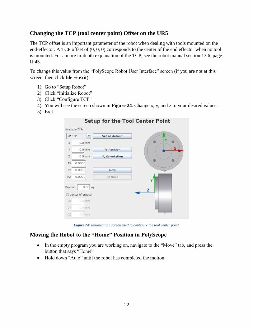
Changing the TCP (tool center point) Offset on the UR5
The TCP offset is an important parameter of the robot when dealing with tools mounted on the
end-effector. A TCP offset of (0, 0, 0) corresponds to the center of the end effector when no tool
is mounted. For a more in-depth explanation of the TCP, see the robot manual section 13.6, page
II-45.
To change this value from the “PolyScope Robot User Interface” screen (if you are not at this
screen, then click file → exit):
1) Go to “Setup Robot”
2) Click “Initialize Robot”
3) Click “Configure TCP”
4) You will see the screen shown in Figure 24. Change x, y, and z to your desired values.
5) Exit
Figure 24: Initialization screen used to configure the tool center point.
Moving the Robot to the “Home” Position in PolyScope
In the empty program you are working on, navigate to the “Move” tab, and press the
button that says “Home”
Hold down “Auto” until the robot has completed the motion.
23
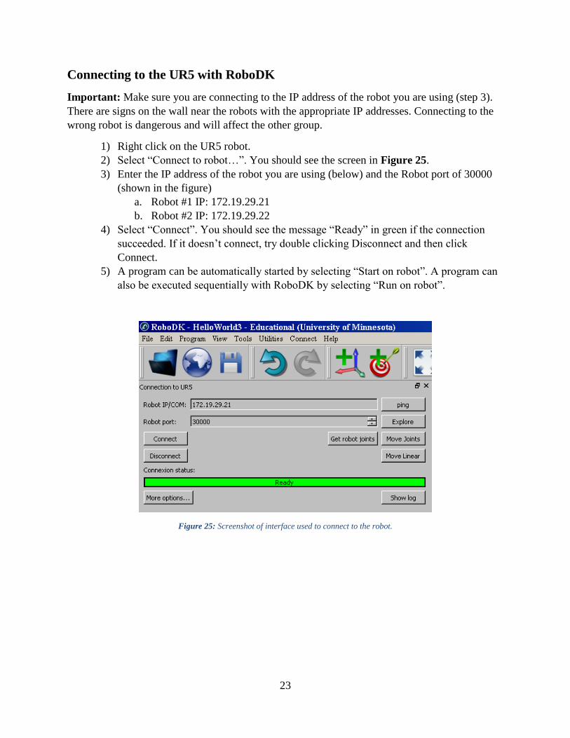
Connecting to the UR5 with RoboDK
Important: Make sure you are connecting to the IP address of the robot you are using (step 3).
There are signs on the wall near the robots with the appropriate IP addresses. Connecting to the
wrong robot is dangerous and will affect the other group.
1) Right click on the UR5 robot.
2) Select “Connect to robot…”. You should see the screen in Figure 25.
3) Enter the IP address of the robot you are using (below) and the Robot port of 30000
(shown in the figure)
a. Robot #1 IP: 172.19.29.21
b. Robot #2 IP: 172.19.29.22
4) Select “Connect”. You should see the message “Ready” in green if the connection
succeeded. If it doesn’t connect, try double clicking Disconnect and then click
Connect.
5) A program can be automatically started by selecting “Start on robot”. A program can
also be executed sequentially with RoboDK by selecting “Run on robot”.
Figure 25: Screenshot of interface used to connect to the robot.