Internet Telephony PBX System
(30/100/200/500 SIP Users Registrations)
IPX-330/IPX-2100/IPX-2200/IPX-2500
Quick Installation Guide
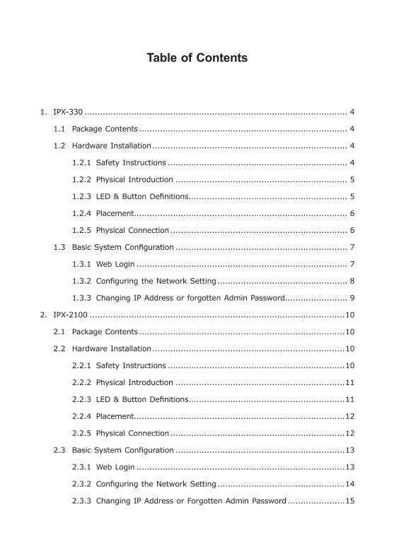
Table of Contents
1. IPX-330 ..................................................................................................... 4
1.1 Package Contents ................................................................................ 4
1.2 Hardware Installation ........................................................................... 4
1.2.1 Safety Instructions ..................................................................... 4
1.2.2 Physical Introduction .................................................................. 5
1.2.3 LED&ButtonDefinitions ............................................................. 5
1.2.4 Placement.................................................................................. 6
1.2.5 Physical Connection .................................................................... 6
1.3 BasicSystemConfiguration .................................................................. 7
1.3.1 Web Login ................................................................................. 7
1.3.2 ConfiguringtheNetworkSetting .................................................. 8
1.3.3 Changing IP Address or forgotten Admin Password ........................ 9
2. IPX-2100 ..................................................................................................10
2.1 Package Contents ...............................................................................10
2.2 Hardware Installation ..........................................................................10
2.2.1 Safety Instructions ....................................................................10
2.2.2 Physical Introduction .................................................................11
2.2.3 LED&ButtonDefinitions ............................................................11
2.2.4 Placement.................................................................................12
2.2.5 Physical Connection ...................................................................12
2.3 BasicSystemConfiguration .................................................................13
2.3.1 Web Login ................................................................................13
2.3.2 ConfiguringtheNetworkSetting .................................................14
2.3.3 Changing IP Address or Forgotten Admin Password ......................15

3. IPX-2200 ..................................................................................................16
3.1 Package Contents ...............................................................................16
3.2 Hardware Installation ..........................................................................16
3.2.1 Safety Instructions ....................................................................16
3.2.2 Physical Introduction .................................................................17
3.2.3 LED&ButtonDefinitions ............................................................17
3.2.4 Placement.................................................................................18
3.2.5 Physical Connection ...................................................................18
3.3 BasicSystemConfiguration .................................................................19
3.3.1 Web Login ................................................................................19
3.3.2 ConfiguringtheNetworkSetting .................................................20
4. IPX-2500 ..................................................................................................22
4.1 Package Contents ...............................................................................22
4.2 Hardware Installation ..........................................................................22
4.2.1 Safety Instructions ....................................................................22
4.2.2 Physical Introduction .................................................................23
4.2.3LED&ButtonDefinitions ............................................................23
4.2.4 Placement.................................................................................24
4.2.5 Physical Connection ...................................................................24
4.3 BasicSystemConfiguration .................................................................25
4.3.1 Web Login ................................................................................25
4.3.2 ConfiguringtheNetworkSetting .................................................26
5. FurtherConfiguration .................................................................................28
4
1. IPX-3301.1 Package ContentsThank you for purchasing PLANET Internet Telephony PBX system, IPX-330. ThisQuickInstallationGuidewill introducehowtofinishthebasicsettingofconnectingthe web management interface and the Internet. Open the box of the Internet Telephony PBX system and carefully unpack it. The box should contain the following items:
z IPX-330 x 1
z Quick Installation Guide x 1
z User’s Manual CD x 1
z Power Adapter x 1 (12V DC)
z RJ45 x 1
If any of the above items are damaged or missing, please contact your dealerimmediately.
1.2 Hardware InstallationThe following are instructions for setting up PLANET IPX-330. Refer to theillustration and follow the simple steps below to quickly install your Internet Telephony PBX system.
1.2.1 Safety InstructionsThe following are the safety instructions for Internet Telephony PBX system before installing.
� The maximum operating temperature of the IPX-330 is 0~40°C, which allowssufficientaircirculation.
� The connections and equipment that supply power to the IPX-330 should be capable of operating safely with the maximum power requirements of the IPX-330.Intheeventofapoweroverload,thesupplycircuitsandsupplywiringshould become hazardous.
� The power adapter must plug into the right supply voltage. Make sure that the supplied power voltage is correct and stable. If the input power voltage is over 10%lowerthanthestandard,itmaycausetheIPX-330tomalfunction.
� Generally,when installed after the final configuration, the productmust complywith the applicable safety standards and regulatory requirements of the country inwhichitisinstalled.Ifnecessary,consultfortechnicalsupport.

5
1.2.2 Physical Introduction
IPX-330
Internet Telephony PBX System
RingingReady/Act
PWR WAN 1 2 SYSLAN
Front Panel of the IPX-330
USB 2 1 Console LAN WANReset
12V DCFXO
Rear Panel of the IPX-330
1.2.3LED&ButtonDefinitions
LED definitions
Front Panel LED Status Description
PWRSteady GreenOff
PBXPowerONPBX Power OFF
SYSBlinking GreenOnOff
System is workingSystem doesn’t bootSystem fails
WANBlinking GreenOnOff
Data is transferringPBX network connection establishedWaiting for network connection
LANBlinking GreenOnOff
Data is transferringPBX network connection establishedWaiting for network connection
FXOSteady RedBlinkingOff
Ready/StandbyRingingModule not available

6
Button definitions
Button Action Description
ResetPress less than 5 secs. System reboot
Press over 6 secs. Reset to factory default
1.2.4 PlacementMake sure the device is placed in a safe environment to avoid equipment failure.
z DONOTplaceanythingontopofthedevice.Excessiveweightcoulddamageit.
z DO NOT obstruct ventilation slots on each side of the IPX-330 or expose it todirect sunlight or other heat sources. Be sure that there is adequate air flowaround the IPX-330.
z PlacetheIPX-330onaflatsurfacetoavoidanydamage.
1.2.5 Physical Connection
USB 2 1 Console LAN WANReset
12V DCFXO
Internet
Video Phone IP Phone IP Phone
Switch Router
ATA MobileSIP Phone
100BASE-TX UTPTelephone wire
2 x FXO
PSTN
Physical Connection Topology of the IPX-330
7
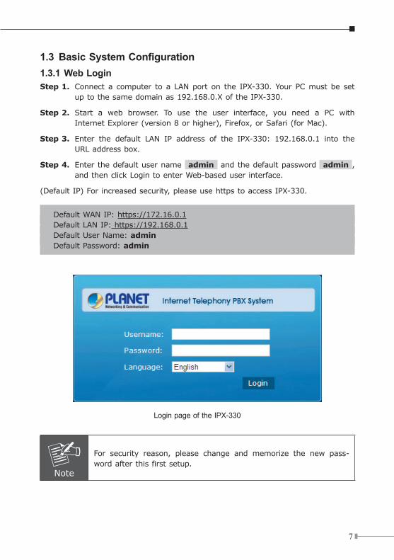
1.3 BasicSystemConfiguration1.3.1 Web LoginStep 1. Connecta computer toa LANporton the IPX-330.YourPCmustbe set
up to the same domain as 192.168.0.X of the IPX-330.
Step 2. Start a web browser. To use the user interface, you need a PC withInternetExplorer(version8orhigher),Firefox,orSafari(forMac).
Step 3. Enter the default LAN IP address of the IPX-330: 192.168.0.1 into theURL address box.
Step 4. Enter the default user name admin and the default password admin ,and then click Login to enter Web-based user interface.
(DefaultIP)Forincreasedsecurity,pleaseusehttpstoaccessIPX-330.
DefaultWANIP: https://172.16.0.1DefaultLANIP: https://192.168.0.1DefaultUserName:adminDefault Password: admin
Login page of the IPX-330
Note
For security reason, please change and memorize the new pass-word after this first setup.
8
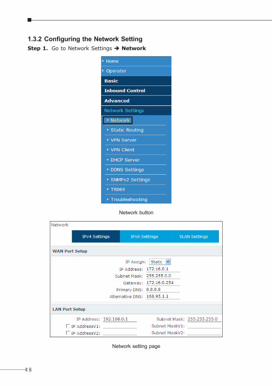
1.3.2ConfiguringtheNetworkSettingStep 1. GotoNetworkSettings Network
Network button
Network setting page

9
Step 2. EdityourWANportIPinformation.
There are three types of Ethernet port connection. They are Static IP, DHCP and PPPoE (Point-to-PointProtocoloverEthernet).Youcanfindadetailed settingprocess in the user manual.
Selection of IP Connection Type
1.3.3 Changing IP Address or forgotten Admin PasswordToresettheIPaddresstothedefaultIPaddress“192.168.0.1”(LAN)orresettheloginpasswordtodefaultvalue,presstheresetbuttononthefrontpanelformore than 6 seconds.Afterthedeviceisrebooted,youcanloginthemanagementWebinterface within the same subnet of 192.168.0.x.
Console LAN WANReset
12V DC
Reset Button
Note
Afterpressing the“Reset”button,all thesystemdatawillbe resettodefault;ifpossible,backuptheconfigfilebeforeresetting.
10
2. IPX-21002.1 Package ContentsThank you for purchasing PLANET Internet Telephony PBX system, IPX-2100.This Quick Installation Guide will introduce how to finish the basic setting ofconnecting the web management interface and the Internet. Open the box of the Internet Telephony PBX system and carefully unpack it. The box should contain the following items:
z IPX-2100 x 1
z Quick Installation Guide x 1
z User’s Manual CD x 1
z Power Adapter x 1 (12V)
z Power Cord x 1
z RJ45 x 1
z Bracket x 2
If any of above items are damaged or missing, please contact your dealerimmediately.
2.2 Hardware InstallationThe following are instructions for setting up PLANET IPX-2100. Refer to theillustration and follow the simple steps below to quickly install your Internet Telephony PBX system.
2.2.1 Safety InstructionsThe following are the safety instructions for Internet Telephony PBX system before installing.
� The maximum operating temperature of the IPX-2100 is 0~40°C. Care must be takentoallowsufficientaircirculation.
� The connections and equipment that supply power to the IPX-2100 should be capable of operating safely with the maximum power requirements of the IPX-2100. In the event of a power overload, the supply circuits and supplywiring should become hazardous.
� The power adapter must plug into the right supply voltage. Make sure that the supplied power voltage is correct and stable. If the input power voltage is over 10%lowerthanthestandard,itmaycausetheIPX-2100tomalfunction.

11
� Generally,when installed after the final configuration, the productmust complywith the applicable safety standards and regulatory requirements of the country inwhichitisinstalled.Ifnecessary,consultfortechnicalsupport.
2.2.2 Physical Introduction
SLOT 1
IPX-2100
Internet Telephony PBX System
RingingFXSReady/Act
FXO/GSMACTLNK
21 3 4
SLOT 2
21 3 4PWR SYS LANWAN
Front Panel of the IPX-2100
SLOT 2 SLOT 1
WANLANConsoleUSBReset Power
12V DC
Rear Panel of the IPX-2100
Note
1.Supporting2slots,usercanbuyexpansionmodulelikeIPX-21FO(4 x FXO) or IPX-21GS (4 x GSM) for extending port service.
2.If IPX-21GS isused,pleasedisablepin lock function.Otherwise,dial out or call in will not be available.
2.2.3LED&ButtonDefinitionsLED definitions
Front Panel LED Status Description
PWRSteady GreenOff
PBXPowerONPBX Power OFF
SYSBlinking GreenOnOff
System is workingSystem doesn’t bootSystem fails
WANBlinking GreenOnOff
Data is transferringPBX network connection is establishedWaiting for network connection
LANBlinking GreenOnOff
Data is transferringPBX network connection is establishedWaiting for network connection

12
FXOSteady RedFlashingOff
Ready/StandbyRingingModule not available
GSMSteady RedFlashingOff
Ready/Standby (SIM card inserted)RingingNoSIMcardinsert
FXSSteady GreenFlashingOff
Ready/StandbyRingingModule not available
Button definitions
Button Action Description
ResetPress less than 5 secs. System reboot
Press over 6 secs. Reset to factory default
2.2.4 PlacementMake sure the device is placed in a safe environment to avoid equipment failure.
z DONOTplaceanythingontopofthedevice.Excessiveweightcoulddamageit.
z DO NOT obstruct ventilation slots on each side of the IPX-2100 or expose itto direct sunlight or other heat source. Be sure that there is adequate air flowaround the IPX-2100.
z PlacetheIPX-2100onaflatsurfacetoavoidanydamage.
2.2.5 Physical Connection
SLOT 2 SLOT 1
WANLANConsoleUSBReset Power
12V DC
FXO Card Life Line Card
Internet
Video Phone IP Phone IP Phone
SwitchRouter
ATA
100BASE-TX UTPTelephone wire
MobileSIP PhoneSingal Line
TelephoneFax
PSTN
2 x FXO + 2 x FXS4 x FXO
Physical Connection Topology of the IPX-2100

13
2.3 BasicSystemConfiguration2.3.1 Web LoginStep 1. ConnectacomputertoaLANportontheIPX-2100.YourPCmustbeset
up to the same domain as 192.168.0.x as the IPX-2100.
Step 2. Start a web browser. To use the user interface, you need a PC withInternetExplorer(versionx8orhigher),Firefox,orSafari(forMac).
Step 3. Enter the default IP address of the IPX-2100: 192.168.0.1 into the URL address box.
Step 4. Enter the default user name admin and the default password admin ,and then click Login to enter Web-based user interface.
(DefaultIP)Forincreasedsecurity,pleaseusehttpstoaccessIPX-2100.
DefaultWANIP: https://172.16.0.1DefaultLANIP: https://192.168.0.1DefaultUserName:adminDefault Password: admin
Login page of the IPX-2100
Note
For security reason, please change and memorize the new pass-word after this first setup.
14
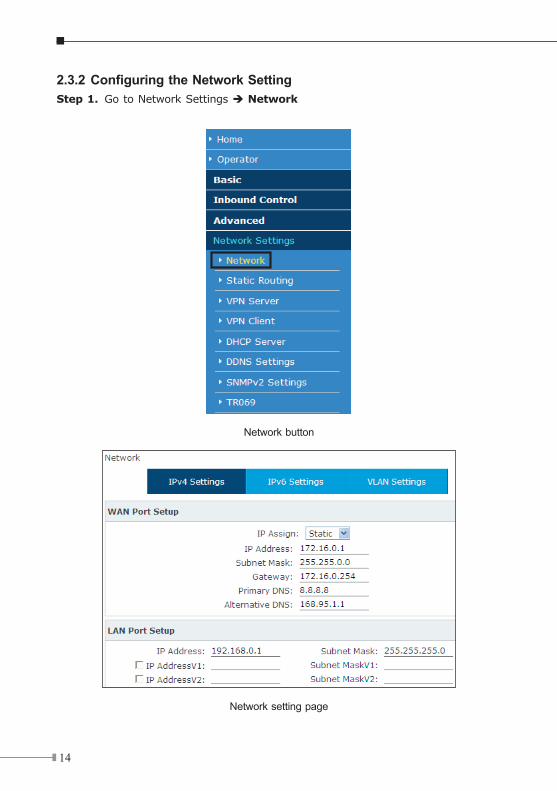
2.3.2ConfiguringtheNetworkSettingStep 1. GotoNetworkSettings Network
Network button
Network setting page
15
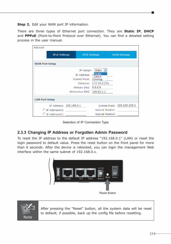
Step 2. EdityourWANportIPinformation.
There are three types of Ethernet port connection. They are Static IP, DHCP and PPPoE (Point-to-PointProtocoloverEthernet).Youcanfindadetailed settingprocess in the user manual.
Selection of IP Connection Type
2.3.3 Changing IP Address or Forgotten Admin PasswordToresettheIPaddresstothedefaultIPaddress“192.168.0.1”(LAN)orresetthelogin password to default value. Press the reset button on the front panel for more than6seconds.After thedevice is rebooted,youcan login themanagementWebinterface within the same subnet of 192.168.0.x.
WANLANConsoleUSBReset Power
12V DC
Reset Button
Note
Afterpressing the“Reset”button,all thesystemdatawillbe resettodefault;ifpossible,backuptheconfigfilebeforeresetting.

16
3. IPX-22003.1 Package ContentsThank you for purchasing PLANET Internet Telephony PBX system, IPX-2200.This Quick Installation Guide will introduce how to finish the basic setting ofconnecting the web management interface and the Internet. Open the box of the Internet Telephony PBX system and carefully unpack it. The box should contain the following items:
z IPX-2200 x 1
z Quick Installation Guide x 1
z User’s Manual CD x 1
z Power Cord x 1
z RJ45 x 1
z Bracket x 2
If any of above items are damaged or missing, please contact your dealerimmediately.
3.2 Hardware InstallationThe following are instructions for setting up PLANET IPX-2200. Refer to theillustration and follow the simple steps below to quickly install your Internet Telephony PBX system.
3.2.1 Safety InstructionsThe following are the safety instructions for Internet Telephony PBX system before installing.
� The maximum operating temperature of the IPX-2200 is 0~40°C. Care must be takentoallowsufficientaircirculation.
� The connections and equipment that supply power to the IPX-2200 should be capable of operating safely with the maximum power requirements of the IPX-2200. In the event of a power overload, the supply circuits and supplywiring should become hazardous.
� The power adapter must plug into the right supply voltage. Make sure that the supplied power voltage is correct and stable. If the input power voltage is over 10%lowerthanthestandard,itmaycausetheIPX-2200tomalfunction.

17
� Generally,when installed after the final configuration, the productmust complywith the applicable safety standards and regulatory requirements of the country inwhichitisinstalled.Ifnecessary,consultfortechnicalsupport.
3.2.2 Physical Introduction
SLOT 1
IPX-2200
Internet Telephony PBX SystemRinging
FXO/GSMFXS
21 3 4
SLOT 2
21 3 4PWR SYS LANWAN
Front Panel of the IPX-2200
USB HDMI LAN
SLOT 2 SLOT 1WAN
100~240V AC
Rear Panel of the IPX-2200
Note
1.Supporting2slots,usercanbuyexpansionmodulelikeIPX-21FO(4 x FXO) or IPX-21GS (4 x GSM) for extending port service.
2.If IPX-21GS isused,pleasedisablepin lock function.Otherwise,dial out or call in will not be available.
3.2.3LED&ButtonDefinitionsLED definitions
Front Panel LED Status Description
PWRSteady GreenOff
PBXPowerONPBX Power OFF
SYSBlinking GreenOff
System is workingSystem Booting or Failed
WANBlinking GreenOff
Data is transferringNoDataTransmitting
LANBlinking GreenOff
Data is transferringNoDataTransmitting
FXOSteady RedFlashingOff
Channel Loading SucceedChannel RingingChannel Loading Failure

18
GSMSteady RedFlashingOff
Channel Loading SucceedChannel RingingChannel Loading Failure
FXSSteady GreenFlashingOff
Channel Loading SucceedChannel RingingChannel Loading Failure
3.2.4 PlacementMake sure the device is placed in a safe environment to avoid equipment failure
z DONOTplaceanythingontopofthedevice.Excessiveweightcoulddamageit.
z DO NOT obstruct ventilation slots on each side of the IPX-2200 or expose itto direct sunlight or other heat source. Be sure that there is adequate air flowaround the IPX-2200.
z PlacetheIPX-2200onaflatsurfacetoavoidanydamage.
3.2.5 Physical Connection
USB HDMI LAN
SLOT 2 SLOT 1WAN
100~240V AC
FXO Card
Internet
Video Phone IP Phone IP Phone
SwitchRouter
ATA MobileSIP Phone
4 x FXO
PSTN GSM
100BASE-TX UTP 1000BASE-T UTPTelephone wire
GSM Card
Physical Connection Topology of the IPX-2200

19
3.3 BasicSystemConfiguration3.3.1 Web LoginStep 1. ConnectacomputertoaLANportontheIPX-2200.YourPCmustbeset
up to the same domain as 192.168.0.x as the IPX-2200.
Step 2. Start a web browser. To use the user interface, you need a PC withInternetExplorer(versionx8orhigher),Firefox,orSafari(forMac).
Step 3. Enter the default IP address of the IPX-2200: https://192.168.0.1 into the URL address box.
Step 4. Enter the default user name admin and the default password admin ,and then click Login to enter Web-based user interface.
(DefaultIP)Forincreasedsecurity,pleaseusehttpstoaccessIPX-2200.
DefaultWANIP: https://172.16.0.1DefaultLANIP: https://192.168.0.1DefaultUserName:adminDefault Password: admin
Login page of the IPX-2200
Note
For security reason, please change and memorize the new pass-word after this first setup.

20
3.3.2ConfiguringtheNetworkSettingStep 1. GotoNetworkSettings Network
Network button
Network setting page

21
Step 2. EdityourWANportIPinformation.
There are three types of Ethernet port connection. They are Static IP, DHCP and PPPoE (Point-to-PointProtocoloverEthernet).Youcanfindadetailed settingprocess in the user manual.
Selection of IP Connection Type

22
4. IPX-25004.1 Package ContentsThank you for purchasing PLANET Internet Telephony PBX system, IPX-2500.This Quick Installation Guide will introduce how to finish the basic setting ofconnecting the web management interface and the Internet. Open the box of the Internet Telephony PBX system and carefully unpack it. The box should contain the following items:
z IPX-2500 x 1
z Quick Installation Guide x 1
z User’s Manual CD x 1
z Power Cord x 1
z RJ45 x 1
z Bracket x 2
If any of above items are damaged or missing, please contact your dealerimmediately.
4.2 Hardware InstallationThe following are instructions for setting up PLANET IPX-2500. Refer to theillustration and follow the simple steps below to quickly install your Internet Telephony PBX system.
4.2.1 Safety InstructionsThe following are the safety instructions for Internet Telephony PBX system before installing.
� The maximum operating temperature of the IPX-2500 is 0~40°C. Care must be takentoallowsufficientaircirculation.
� The connections and equipment that supply power to the IPX-2500 should be capable of operating safely with the maximum power requirements of the IPX-2500. In the event of a power overload, the supply circuits and supplywiring should become hazardous.
� The power adapter must be plugged into the right supply voltage. Make sure that the supplied power voltage is correct and stable. If the input power voltage isover10%lowerthanthestandard,itmaycausetheIPX-2500tomalfunction.
� Generally,when installed after the final configuration, the productmust complywith the applicable safety standards and regulatory requirements of the country inwhichitisinstalled.Ifnecessary,consultwithtechnicalsupport.

23
4.2.2 Physical Introduction
SLOT 1
IPX-2500
Internet Telephony PBX SystemRinging
FXO/GSMFXS
21 3 4
SLOT 2
21 3 4PWR SYS LANWAN
Front Panel of the IPX-2500
USB HDMI LAN
SLOT 2 SLOT 1WAN
100~240V AC
Rear Panel of the IPX-2500
Note
Supporting 2 slots, user can buy expansionmodule like IPX-21FO(4 x FXO) or IPX-21GS (4 x GSM) for extending port service.
4.2.3LED&ButtonDefinitionsLED definitions
Front Panel LED Status Description
PWRSteady GreenOff
PBXPowerONPBX Power OFF
SYSBlinking GreenOff
System is workingSystem Booting or Failed
WANBlinking GreenOff
Data transmittingNoDataTransmitting
LANBlinking GreenOff
Data transmittingNoDataTransmitting
FXOSteady RedFlashingOff
Channel Loading SucceededChannel RingingChannel Loading Failed
GSMSteady RedFlashingOff
Channel Loading SucceededChannel RingingChannel Loading Failed
FXSSteady GreenFlashingOff
Channel Loading SucceededChannel RingingChannel Loading Failed

24
4.2.4 PlacementMake sure the device is placed in a safe environment to avoid equipment failure.
z DONOTplaceanythingontopofthedevice.Excessiveweightcoulddamageit.
z DONOTobstruct ventilation slots on each side of the IPX-2500or expose it todirect sunlight or other heat sources. Be sure that there is adequate air flowaround the IPX-2500.
z PlacetheIPX-2500onaflatsurfacetoavoidanydamage.
4.2.5 Physical Connection
USB HDMI LAN
SLOT 2 SLOT 1WAN
100~240V AC
FXO Card
Internet
Video Phone IP Phone IP Phone
SwitchRouter
ATA MobileSIP Phone
4 x FXO
PSTN GSM
100BASE-TX UTP 1000BASE-T UTPTelephone wire
GSM Card
Physical Connection Topology of the IPX-2500
25
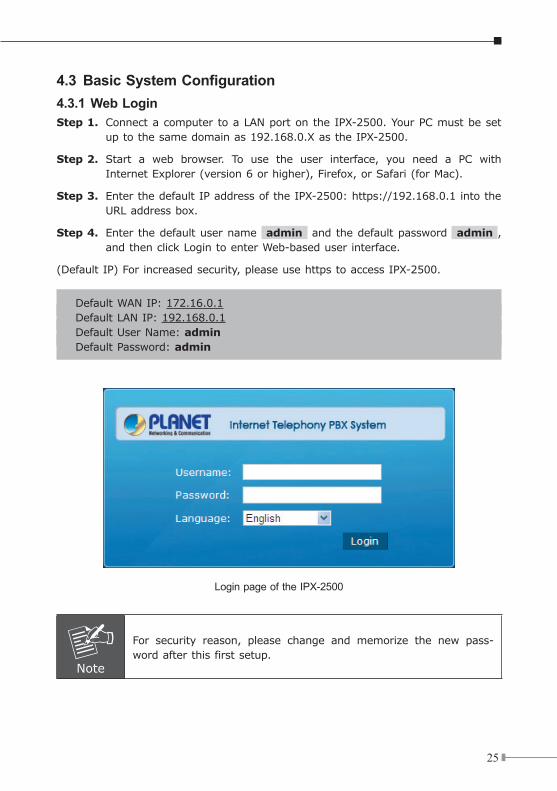
4.3 BasicSystemConfiguration4.3.1 Web LoginStep 1. ConnectacomputertoaLANportontheIPX-2500.YourPCmustbeset
up to the same domain as 192.168.0.X as the IPX-2500.
Step 2. Start a web browser. To use the user interface, you need a PC withInternetExplorer(version6orhigher),Firefox,orSafari(forMac).
Step 3. Enter the default IP address of the IPX-2500: https://192.168.0.1 into the URL address box.
Step 4. Enter the default user name admin and the default password admin ,and then click Login to enter Web-based user interface.
(DefaultIP)Forincreasedsecurity,pleaseusehttpstoaccessIPX-2500.
DefaultWANIP: 172.16.0.1DefaultLANIP: 192.168.0.1DefaultUserName:adminDefault Password: admin
Login page of the IPX-2500
Note
For security reason, please change and memorize the new pass-word after this first setup.

26
4.3.2ConfiguringtheNetworkSettingStep 1. GotoNetworkSettings Network
Network button
Network setting page
27
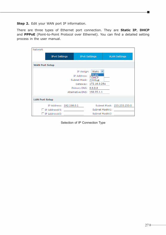
Step 2. EdityourWANportIPinformation.
There are three types of Ethernet port connection. They are Static IP, DHCP and PPPoE (Point-to-PointProtocoloverEthernet).Youcanfindadetailed settingprocess in the user manual.
Selection of IP Connection Type
28
5.FurtherConfigurationThankyou forpurchasingPLANETproducts. Theabove steps introduce the simpleconfigurations of the IPX-330, IPX-2100, IPX-2200 and IPX-2500. For furtherconfiguration, please refer to the user’s manual on the CD. If you have otherquestions, please contact the local dealer or distributor where you purchased this product.
You also can browse our online FAQ resource at PLANET Web site first to checkif it could solve your issue. If you needmore support information, please contactPLANETsupportteam.
PLANETonlineFAQ:http://www.planet.com.tw/en/support/faq.php
IP Telephony support team mail address :[email protected]
Copyright © PLANET Technology Corp. 2016.Contents are subject to revision without prior notice.PLANET is a registered trademark of PLANET Technology Corp. All other trademarks belong to their respective owners.