The World Leader in High Performance Signal Processing Solutions
Interfacing Audio and Video Converters to Blackfin Processors
Presented By: David Katz
Senior Blackfin Applications Engineer

2
About this Module
!This presentation will familiarize the user with the principles behind connecting Blackfin processors to audio and video devices.
!Prerequisites: Basic working knowledge of audio and video fundamentals
3
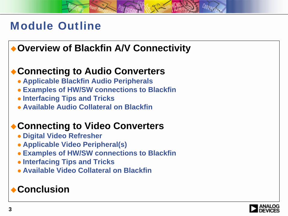
Module Outline
!Overview of Blackfin A/V Connectivity
!Connecting to Audio Converters" Applicable Blackfin Audio Peripherals" Examples of HW/SW connections to Blackfin" Interfacing Tips and Tricks " Available Audio Collateral on Blackfin
!Connecting to Video Converters" Digital Video Refresher" Applicable Video Peripheral(s)" Examples of HW/SW connections to Blackfin" Interfacing Tips and Tricks" Available Video Collateral on Blackfin
!Conclusion

4
Basic A/V System Connections
Audio
DAC
BlackfinProcessor
Audio
ADC
Video
DAC
Video
ADC

5
Why is Blackfin well-suited for A/V applications?
DMA capabilitiesPeripheral mix
Dynamic Power ManagementWide Product Portfolio
High clock speedsFlexible instruction set
Scalability across and within applications
Multimedia-grade performance
Powerful Connectivity and Data Handling
Capabilities

6
Connecting to Audio Converters

7
Blackfin Audio Interface Usage
!Two-Wire Interface (TWI) and Serial Peripheral Interface (SPI)" Forward channel used to configure and control audio converters" Reverse channel relays feedback info from converters
!SPORT" Used as data channel for audio data
!SPORT TX connects to audio DAC!SPORT RX connects to audio ADC!Full-duplex SPORT RX/TX connects to audio codec
" In some codecs (e.g., AC97), SPORT also can serve as the codec control channel

8
SPI Control Interface! Compatible with Motorola SPI standard! Full-duplex serial interface operating up to 33 Mbps! Supports Master/Slave and Multimaster environments! 3-pin communication interface
MOSI = Master Output, Slave InputMISO = Master Input, Slave OutputSCK = Serial Clock
! SPISS = SPI Chip Select Input Allows another SPI device (Master) to select the processor (Slave)
!SPISELx = SPI Slave SelectsAllow the processor (Master) to select other SPI devices (Slaves)

9
TWI Control Interface
! I2C-compatible Two-Wire Interface!Provides simple exchange method of control & data between
multiple devices!Simultaneous Master and Slave operation!Supports speeds up to 400 kbits/sec!SCL (clock) and SDA (data) pins comprise the interface
Source: Philips I2C Spec

10
SPORT: High-speed synchronous serial port
! Fully independent RX and TX channels! Primary and secondary data RX/TX pins! Operates up to 66 Mbps (133 Mbps
including secondary RX/TX channel)! Supports word lengths of 3-32 bits! Programmable internal/external clocks
and frame syncs ! Built-in hardware µ-Law and A-Law
companding (for vocoders)! Support for multichannel (TDM) interfaces
for networked communication! I2S signaling support

11
SPORT I2S Functionality
! Industry standard developed by Philips for stereo audio transmission over a 3-wire interface
!Data always transmits in MSB format!Consists of Serial Clock, Word Select (Left/Right) and Data!Each SPORT accommodates 4 TX and 4 RX I2S audio
channels

12
Connecting to Audio ADCs: AD1871
13
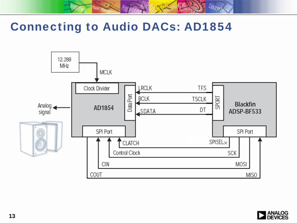
Connecting to Audio DACs: AD1854

14
Tips & Tricks for Connecting to Audio Converters
!TWI" Both SCL and SDA need pullup resistors; they are never driven
high (per I2C spec)
!SPI" Connect all MISO pins to MISO pins, and MOSI to MOSI
!Tie all MOSI pins together; tie all MISO pins together" Make sure MOSI and MISO pins are not swapped
!SPORT" SPORTs in Multi-Channel Mode that master the clocks and frame
syncs should not connect TFS to RFS. ! In this mode, the TFS frames the active TX channel data, acting as a TX Data
Valid (TDV) pin." Use proper termination for clock and frame sync signals
15
Additional Collateral for Audio Development
! Software" VisualDSP++ Tools Suite
! Includes peripheral drivers for configuration via standard API! Includes complete audio device drivers
" Standard API for audio converters, with many devices supported−AD1871 ADC−AD1854 DAC−AD1836A codec
" EZ-Kit and EZ-Extender Card code examples! Integrate peripheral and codec drivers!Provide examples of data flows and system configuration
! Hardware" EZ-Kits + EZ-Extender Cards include on-board audio converters
!Allow for quick system prototyping!Reference Schematics and BOMs available
! VisualAudio® algorithm development tool!Streamlines design of audio systems
16
Connecting to Video Converters

17
Outline for Connecting to Video Converters
!System Video Flow!Some Digital Video Basics
" ITU-R BT.601" ITU-R BT.656
!Blackfin Parallel Peripheral Interface (PPI)!Connecting to Video Sources!Connecting to Video Displays!Sample Video System Diagram

18
System Video Flow

19
Digital Video Refresher
20
ITU-R BT.601 Concepts!Specifies encoding parameters for digital TV
!Color Spaces Supported" RGB (Red, Green, Blue)
! Intuitive format, but channels are highly correlated!3 color values per pixel
" RGB888 format implies 8 bits each of Red, Green and Blue" RGB666 or RGB565 imply 5 or 6 bits per color channel
" YCbCr (Y=luma, Cx=chroma)!Generated via RGB signals!Highly uncorrelated, thus providing better compression characteristics!4:2:2 YCbCr is recommended by BT.601
" One luma and one chroma (Cr or Cb) value per pixel
!8-bit or 10-bit quantization of RGB or YCbCr components
!NTSC and PAL normalized to 720 active pixels per line" NTSC (60 fields/sec) has 525 lines (including blanking)" PAL (50 fields/sec) has 625 lines (including blanking)

21
ITU-R BT.601 Timing
!HSYNC is the horizontal synchronization signal. It demarcates the start of active video on each row (left to right) of a video frame.
!VSYNC is the vertical synchronization signal. It defines the start (top to bottom) of a new video image.
!FIELD distinguishes, for interlaced video, which field (odd or even) of a video frame is currently being displayed. This signal is not applicable for progressive-scan video systems.
!CLOCK is the data clock for each pixel component.
22
ITU-R BT.656 Concepts
!Defines the physical interfaces and data streams necessary to implement ITU-R BT.601
!Bit-parallel and bit-serial modes
!27 MHz nominal clock and 8 or 10 data lines (for bit-parallel mode)
!Embedded hardware signaling (H, V, F)
!Supports interlaced and progressive formats
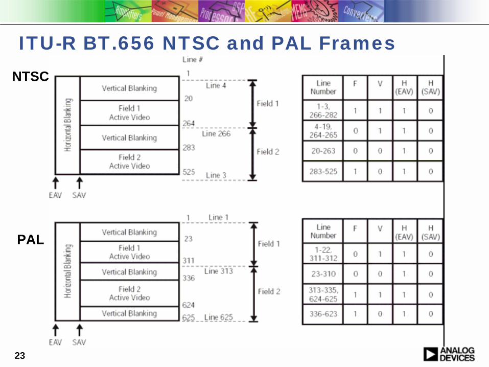
23
ITU-R BT.656 NTSC and PAL FramesNTSC
PAL

24
ITU-R BT.656 Data Stream Format

25
Blackfin Video Interface: PPI

26
Parallel Peripheral InterfaceNot needed for BT.656 modes Video Sources and
Displays
• Supports ITU-R BT.656 and BT.601 Video Converter Interfaces• General-Purpose Mode supports data converter apps
27
Parallel Peripheral Interface
!Bidirectional, half-duplex interface!Supports bit-parallel ITU-R BT.656 recommendation!Up to 16 data lines, 1 clock, 3 Frame Syncs!Programmable signal polarity choices for syncs and clock
!Bandwidth-saving features"Selective reception of BT.656 Active and Blanking regions "Can optionally ignore Field 2 of a BT.656 frame"Can skip even or odd data elements "Works hand-in-hand with 2D DMA Engine

28
Connecting to Video Sources
29
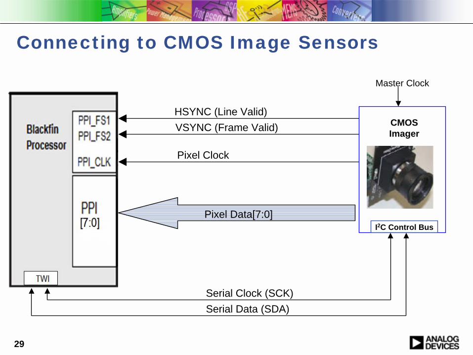
Connecting to CMOS Image Sensors
Pixel Data[7:0]
HSYNC (Line Valid)
Pixel Clock
VSYNC (Frame Valid) CMOS Imager
Master Clock
I2C Control Bus
Serial Clock (SCK)Serial Data (SDA)

30
Connecting to CMOS Image Sensors
! Blackfin EZ-Extender cards and EZ-Kits support connection to products from many major vendors" Micron" Omnivision" Kodak
! Example: Micron’s CMOS Imager “Headboard” provides a common 26-pin interface for a whole family of sensors

31
Connecting to Analog Sources: ADV7183B Video ADC
32
Connecting to Video Displays
33
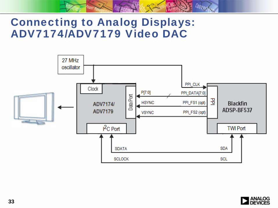
Connecting to Analog Displays: ADV7174/ADV7179 Video DAC
34
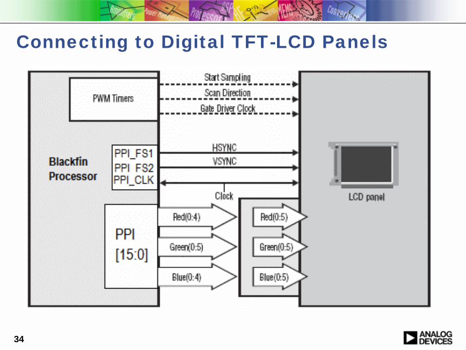
Connecting to Digital TFT-LCD Panels
35
Tips and Tricks for Connecting to Video Devices
!Use ITU-R BT.656 mode whenever possible!Eliminates timing incongruities in sync modes
!Pay close attention to default converter settings
!Make sure clock source is as clean as possible
!For RGB565 connections, do not ground the LSB of R or B
" Instead, tie the MSB of Red to the LSB of Red at the LCD panel" Do the same for Blue" This insures a full dynamic range is achievable on R and B channels

36
Additional Collateral for Video Development
!Software" VisualDSP++ Tools Suite
! Includes peripheral drivers for configuration via standard API! Includes many complete video device drivers
" ADV7183B" ADV7171, ADV7174, ADV7179" CMOS Sensors from Micron, Kodak and Omnivision" LCD displays from multiple vendors
" EZ-Kit and EZ-Extender Card code examples! Integrate peripheral and codec drivers!Provide examples of data flows and system configuration
!Hardware" EZ-Kits + EZ-Extender Cards
! Include CMOS sensor and LCD panel interfaces!Allow for quick system prototyping!Reference Schematics and BOMs available

37
Video System Example
BF561(MJPEG Encoder)
ADV7179ADV7183B
USBNET2272
USB 2.0 to Host PC- Compressed Video flows from Blackfin to Host PC
EZ-USB EXTENDER
- *.AVI files get stored to local hard drive
Video Pass-Through
Stack EZ-USB Extender onto ADSP-BF561 EZ-KIT
AD
SP-BF561 EZ-K
IT

38
Conclusion
!The Blackfin Processor architecture is very well suited for multimedia system design
!Blackfin devices provide versatile connectivity to A/V peripherals
!Collateral available to speed system design
39
! Collateral to jump-start development
" VisualDSP++ tools suite for Blackfin Processorswww.analog.com/blackfin/visualdsp
" Blackfin EZ Kits and EZ-Extender Cardswww.analog.com/evaluationkits
" Application Noteswww.analog.com/ee-notes
" BOLD online training moduleswww.analog.com/BOLD
" VisualAudio® algorithm development toolwww.analog.com/visualaudio
" Embedded Media Processing bookwww.theEMPbook.com
! Click “Ask A Question” buttonOr send an email to [email protected]
Additional Information