ADVANCED CONJUGATED SYSTEMS TOWARDS REALIZATION OF
STABLE n-TYPE MATERIALS AND HIGH-PERFORMANCE
ELECTROCHROMIC POLYMERS
A THESIS SUBMITTED TO
THE GRADUATE SCHOOL OF NATURAL AND APPLIED SCIENCES
OF
MIDDLE EAST TECHNICAL UNIVERSITY
BY
KIANOUSH GHASEMI. A. F.
IN PARTIAL FULFILLMENT OF THE REQUIREMENTS
FOR
THE DEGREE OF MASTER OF SCIENCE
IN
POLYMER SCIENCE AND TECHNOLOGY
SEPTEMBER 2018

Approval of the thesis:
ADVANCED CONJUGATED SYSTEMS TOWARDS REALIZATION OF
STABLE n-TYPE MATERIALS AND HIGH-PERFORMANCE
ELECTROCHROMIC POLYMERS
submitted by KIANOUSH GHASEMI. A. F. in partial fulfillment of the
requirements for the degree of Master of Science in Polymer Science and
Technology Department, Middle East Technical University by,
Prof. Dr. Halil Kalıpçılar
Dean, Graduate School of Natural and Applied Sciences
Prof. Dr. Necati Özkan
Head of Department, Polymer Science and Technology
Assoc. Prof. Dr. Görkem Günbaş
Supervisor, Polymer Science and Technology, METU
Examining Committee Members:
Prof. Dr. Levent Toppare
Department of Chemistry, METU
Assoc. Prof. Dr. Görkem Günbaş
Polymer Science and Technology, METU
Prof. Dr. Ali Çırpan
Department of Chemistry, METU
Assist. Prof. Dr. Salih Özçubukçu
Department of Chemistry, METU
Prof. Dr. Yasemin Udum
Dept. of Ad. Tech., Gazi Uni.
Date: 07.09.2018

iv
I hereby declare that all information in this document has been obtained and
presented in accordance with academic rules and ethical conduct. I also declare
that, as required by these rules and conduct, I have fully cited and referenced all
material and results that are not original to this work.
Name, Surname:
Signature:
Kianoush Ghasemi. A. F.
v
ABSTRACT
ADVANCED CONJUGATED SYSTEMS TOWARDS REALIZATION OF
STABLE n-TYPE MATERIALS AND HIGH-PERFORMANCE
ELECTROCHROMIC POLYMERS
Ghasemi. A. F., Kianoush
Master of Science, Polymer Science and Technology
Supervisor: Assoc. Prof. Dr. Görkem Günbaş
September 2018, 99 pages
Electrochromic materials attracted tremendous amount of interest both in academia
and industry in recent decades. These materials owe their popularity to their
fascinating fundamental spectroelectrochemical properties and their potential
commercial applications. On the spectrum of electrochromic materials,
electrochromic polymers drawn the attention of the scientific community due to
properties such as high flexibility, low-power consumption, ease of processing and
low processing cost. Polymers which represent one of the three complementary colors
(red, green, and blue) in their reduced state and high transmissivity in oxidized state
are fundamental for electrochromic devices and displays. With this regard and
following previous works of our group in designing green to transmissive polymers
utilizing EDOT as the donor unit, we aimed to create better performance green
materials using ProDOT instead of EDOT. ProDOT containing conjugated systems
are expected to outperform their EDOT analogues considering the fact that ProDOT
homopolymers outperforms EDOT containing donor-acceptor type polymers. Hence,
we introduced ProDOT units to benzooxadiazole and quinoxaline for reaching the
required donor-acceptor match towards realization of a green to transmissive polymer
with superior properties. Besides, despite the fact that stable n-dopable conjugated
vi
polymers are infrequent, they have a broad potential of application in organic
electrochemical transistors and OFETs. The stable n-type materials can be used for
realization of complex organic electronic devices with p-i-n type junctions. On this
path, perylene diimide (PDI) and its derivatives represent one of the most promising
classes of electron acceptors because of their outstanding chemical and physical
properties, including high electron mobility, strong intermolecular π-π interactions,
and high absorption coefficients. In this study, we coupled PDI with electron-rich
EDOT units to realize easily n-dopable conjugated polymer systems that can be
prepared by electrochemical polymerization techniques
Keywords: Electrochromism, Green to transmissive polymers, ProDOT, Conjugated
polymers, n-type materials
vii
ÖZ
YÜKSEK PERFORMANSLI ELEKTROKROMİK POLİMERLERİN VE
KARARLI n-TİPİ MALZEMELERİN GELİŞTİRİLMESİ İÇİN İLERİ
SEVİYE KONJUGE SİSTEMLER
Ghasemi. A. F., Kianoush
Yüksek Lisans, Polimer Bilim ve Teknolojisi
Tez Danışmanı: Doç. Dr. Görkem Günbaş
Eylül 2018, 99 sayfa
Elektrokromik malzemeler son yıllarda akademide ve endüstride yoğun ilgi
çekmektedir. Bu malzemeler popülerliklerini etkileyici temel spektroelektrokimyasal
özelliklerine ve potansiyel ticari uygulamalarına borçludurlar. Çeşitli elektrokromik
malzemeler arasında yüksek esneklik, düşük güç tüketimi, işleme kolaylığı ve düşük
işleme maliyeti özelliklerine sahip olan polimerler bilim camiasının özellikle ilgisini
çekmiştir. İndirgenmiş hallerinde üç tamamlayıcı rengi (kırmızı, yeşil ve mavi) temsil
eden ve oksitlenmiş hallerinde ise yüksek şeffaflık gösteren polimerler elektrokromik
görüntüleme cihazlarında kullanılmaktadırlar. Araştırma grubumuzun daha önceki
çalışmalarında donor ünitesi olarak EDOT kullanarak yeşilden şeffafa dönen
polimerin daha yüksek performanslı olanlarını başarmak adına EDOT ünitesi ProDOT
ünitesi ile değiştirilmiştir. ProDOT homopolimerlerin PEDOT’dan daha üstün özellik
göstermesi ve ProDOT içeren donor-akseptör tipi polimerlerin de EDOT’lu olanlara
oranla daha yüksek performans göstermektedir. Bu sebeple ProDOT ünitesi
benzooksadiazol ve kuinoksalin ile eşleştirilerek uygun donör-akeptör eşleşmesini
yakalayıp daha üstün özelliklere sahip yeşilden şeffafa dönen polimerler eldesi
amaçlanmıştır. Ayrıca, yüksek kararlılığa sahip n-tipi doplanabilen konjuge
polimerler çeşitlerinin seyrek olmasına rağmen organik elektrokimyasal transistör ve
viii
OFET cihazların geniş bir uygulama potansiyeline sahiptirler. Kararlı n-tipi
materyaller p-i-n tipi ekleme sahip kompleks organik elektronik cihazların
geliştirilmesinde kullanılabilirler. Bu yolda, perilen diimide (PDI) ve türevleri; yüksek
elektron hareketliliği, güçlü moleküller arası π-π etkileşimleri, ve yüksek absorpsiyon
katsayıları dahil olmak üzere etkileyici kimyasal ve fiziksel özellikleri sayesinde
elektron alıcıları grubunda en önemli sınıflardan birini temsil etmektedirler. Bu
çalışmada, PDI ünitesi elektronca zengin EDOT ünitesi bu sistem davranışlarında
temel bilgiler ve yeni sonuçlar elde etmek üzere birleştirilmiş ve elektrokimyasal
yöntemlerle polimerleştirilmiştir
Anahtar Kelimeler: Elektrokromizm, Yeşil-şeffaf polimerler, ProDOT, Konjuge
polimerler

ix
To family

x
ACKNOWLEDGMENTS
Although words are so asthenic to take the responsibility to transfer what heart means,
but we invented them and we split our path from our biological ancestors, so I try to
harness the words to tender my sincere gratitude to the following esteemed people
who were always on my side or in my mind and helped me to make this study happen.
My parents who gifted me life as the first blessing. Parents are such those things that
are always there, since the time of your birth, like the sun and the moon, so you
sometimes forget that you owe them everything, you owe them your life. I thank them
for their kindness, understanding and their patience towards their stubborn son who
always put them in hard tough emotional situations.
My dear lovely sister, Katayoon, whose soul, is my soul in another body. We have
been all along throughout these decades of our lives, actually and spiritually, mentally
and emotionally. I thank her so much because of carrying this heavy burden of being
the child present with our parents within all these years of my absence, taking care of
herself and consequently taking care of our parents. I love you.
My dear adviser Assoc. Prof. Dr. Görkem Günbaş for supervising, guiding and
accompanying me in all steps of my work and more importantly giving me the chance
of being a member of his research group and working in his laboratory. During the
period of my study, he was always more of a friend whose leads had enlightened the
blurry pathway of the new science.
Dear Prof. Dr. Yasemin Udum. No doubt that all of us owe her the electrochemistry
part of our thesis, but it’s not just that, because when it comes to electrochemistry we
are all in rush to finish final works and we put this tremendous pressure on her to
prioritize our work. She is so dedicated, hardworking and so kind to explain to me
what I needed to know about her work in a short time, just like electrochemistry in a
nutshell.

xi
Dear Assist. Prof. Dr. Selcuk Yerci, who acquainted me in the first place with
Dr.Günbaş and put the very first stone of this building.
The esteemed committee members, Prof. Dr. Levent Toppare, Prof. Dr. Ali Çırpan,
Prof. Dr. Yasemin Udum, and Assist. Prof. Dr. Salih Özçubukçu for their kind
consideration and making me honored by attending my thesis jury session.
And all my friends;
Dear lovely Gizem Atakan, the supervisor of our lab, for her kindness, conscientious,
companion and friendship. I cannot even count how many times I interrupted her work
just to check my NMR results and she never said no, not even once and that’s not the
only one.
My brother, Mustafa Yaşa, for those all days and nights of working together in the lab,
the courses that we took with each other, his always and ever presence around at school
never let me feel alone, answering my questions and accompanying me in researches
and practical works. I have been around and he is one of the best people who I have
ever seen in my life. He is a brilliant guy with a brilliant future.
Seza Göker, the hardworking companionate and brainy friend of mine. She may have
come later than all friends who I had the opportunity to know in METU, but our
friendship was immediately elevated to another level, that much I can say that
sometimes she was more worried about me and my job than me.
Aliekber Karabağ, my strong friend who really is a delineation of hardworking and
combatant. He was always patient and friendly the same as supporting and careful in
devoting the knowledge that he earned through hard work out of difficulties. He is the
man of acts.
Dear Figen Varlıoğlu, my lovely dreamer friend with a glass heart and an iron will.
She was always so kind and so compassionate. I thank her so much for listening to my
long never-ending boring speeches about life and philosophy of being, always patient,
always merciful.

xii
My man, Osman Karaman, for his generosity, brotherhood and friendship. I thank him
so much because of being so munificent to share his glasses with me, accompany me
with checking my NMRs and working shoulder by shoulder with me at weekend in
the lab. I also thank him for listening to Arctic Monkeys for hours with me in the lab
and never say enough.
Cansu İğci, for her kind help and warm welcome to me along with others when I came
to the lab for the first time. She was and still is one of the bests and I learnt a lot from
her.
Gülce Öklem. Everyone knows how to set up chromatography columns, I learnt her
method and I got several pure products out of those chromatography columns.
Other dear friends from GÜNBAŞ research group, Dilay Kepil, Cevahir Ceren Akgül,
Gülsüm Güneş, Merve Canyurt, Esra Bağ, Selin Akpınar, Sultan Çetin, Nihan
Yılmazer and Hayriye Kocademirci for helping to make the meaning of the word
“Group” real.
Last and the most, to my dear Simge for reminding me the blue sky.
With indulgences with everybody else that their names aren’t mentioned here because
of lack of my memory, I want to thank them by heart and propound this lovely massage
by Albert Camus, the French philosopher and journalist, to them; “But, heart has its
own memory.”
xiii
TABLE OF CONTENTS
ABSTRACT… ................................................................................................... v
ÖZ .................................................................................................................... vii
ACKNOWLEDGEMENTS ............................................................................... x
TABLE OF CONTENTS ................................................................................ xiii
LIST OF FIGURES ....................................................................................... xvii
LIST OF ABBREVIATIONS ........................................................................ xxii
CHAPTERS
CHAPTER 1 ...................................................................................................... 1
INTRODUCTION ............................................................................................. 1
1.1. Conjugated Polymers ................................................................................. 1
1.2. Conduction in Conjugated Polymers ............................................................... 2
1.2.1. Band Theory ............................................................................................ 2
1.2.2. Conduction in Conjugated Polymers ....................................................... 4
1.2.3. Solitons, Polarons, and Bipolarons .......................................................... 4
1.2.4. Doping ..................................................................................................... 5
1.2.5. What Affects the Band Gap? ................................................................... 6
1.2.6. Resonance Energy.................................................................................... 6
1.2.7. Electron-Withdrawing Groups ................................................................. 6
1.2.8. Electron-donating Groups ........................................................................ 7
1.2.9. Donor Acceptor Approach ....................................................................... 8
1.3. Stable N-Type Conjugated Polymers .............................................................. 8
1.4. Conducting Polymer Characterization ............................................................. 9
xiv
1.4.1. Chromism ............................................................................................... 10
1.4.2. Electrochromism .................................................................................... 10
1.4.2.1. Electrochromic Material Types ....................................................... 11
1.4.2.1.1. Viologens (1,1’-disubstituted-4,4’-bipyridylium salts) ............ 11
1.4.2.1.2. Prussian Blue System ............................................................... 11
1.4.2.1.3. Metal Oxides ............................................................................. 12
1.5. Conjugated Conducting Polymers ................................................................. 12
1.6. Utilized Color Models for Simple Electrochromic Display Devices ............. 14
1.6.1. Standard Red-Green-Blue (sRGB) Color Space .................................... 14
1.6.1.1. Blue to Transmissive Electrochromic Polymers ............................. 15
1.6.1.2. Green to Transmissive Electrochromic Polymers ........................... 15
1.6.1.3. Red to Transmissive Electrochromic Polymers .............................. 16
1.6.2. Multicolor Electrochromic Polymers: Color Control ............................ 17
1.7. Polymerization Methods ................................................................................ 21
1.7.1. Electropolymerization ............................................................................ 21
1.7.2. Oxidative Chemical Polymerization ...................................................... 23
1.7.2.1. Suzuki-Miyaura Coupling ............................................................... 23
1.7.2.2. Stille Coupling ................................................................................. 24
1.7.2.3. Yamamoto Coupling ....................................................................... 24
1.7.2.4. Knoevenagel Condensation ............................................................. 25
1.7.2.5. Tamao-Kumada-Corriu Coupling ................................................... 25
1.7.2.6. Sonogashira Coupling ..................................................................... 25
1.8. Aim of This Work .......................................................................................... 26
CHAPTER 2 ................................................................................................... 29
EXPERIMENTAL ........................................................................................... 29
2.1. Materials & Methods ..................................................................................... 29
2.1.1. Synthesis of 2-decyl-1-tetradecylbromide ............................................. 30
2.1.2. Synthesis of N-(2-decyltetradecyl)phathalimide ................................... 30
2.1.3. Synthesis of 2-decyl-1-tetradecylamine ................................................. 31
2.2. Synthesis of (PDI-EDOT) .............................................................................. 31
xv
2.2.1. Synthesis of PDI-2Br ............................................................................. 32
2.2.2. Synthesis of N,N’-bis(2-decyltetradecyl)-1,6-dibromo-3,4,9,10-perylene
diimide ............................................................................................................. 32
2.2.3. Synthesis of tributyl(2,3-dihydrothieno[3,4-b][1,4]dioxin-5-yl)stannane
......................................................................................................................... 33
2.2.4. Synthesis of 2,9-bis(2-decyltetradecyl)-5,12-bis(2,3-dihydrothieno[3,4-
b][1,4]dioxin-5-yl)anthrax[2,1,9-def:6,5,10-d'e'f']diisoquinoline-
1,3,8,10(2H,9H)tetraone (PDI-EDOT) ............................................................ 34
2.3. Synthesis of stannylated Pro-DOT ................................................................ 35
2.3.1. Synthesis of diethyl 2,2-dipentadecylmalonate ..................................... 35
2.3.2. Synthesis of 2,2-sipentadecyl-1,3-propanediol ...................................... 36
2.3.3. Synthesis of 2,3,4,5-tetrabromothiophene ............................................. 36
2.3.4. Synthesis of 3,4-dibromothiophene ....................................................... 37
2.3.5. Synthesis of 3,4-dimethoxythiophene.................................................... 37
2.3.6. Synthesis of 3,3'-didodecyl-3,4-dihydro-2H thieno[3,4b][1,4]dioxepine
(ProDOT) ......................................................................................................... 38
2.3.7. Synthesis of tributyl(3,3-diundecyl-3,4-dihydro-2H-thieno[3,4-
b][1,4]dioxepin-6-yl) stannane ........................................................................ 39
2.3.7.1. Synthesis of (3,3-didecyl-3,4-dihydro-2H-thieno[3,4-b][1,4]dioxepin-6-yl)trimethylstannane ....................................................... 40
2.4. Synthesis of QUIN-ProDOT .......................................................................... 40
2.4.1. Synthesis of 5,8-dibromo-2,3-bis(4-((2-octyldodecyl)oxy)phenyl)
quinoxaline....................................................................................................... 40
2.4.2. Synthesis of 5,8-bis(3,3-diundecyl-3,4-dihydro-2H thieno[3,4-
b][1,4]dioxepin-6-yl)-2,3-bis(4 (dodecyloxy)phenyl)quinoxaline (Quin-Pro-
DOT) ................................................................................................................ 41
2.5. Synthesis of (BENZ-ProDOT) ...................................................................... 42
2.5.1. Synthesis of 4,7-bis(3,3-didecyl-3,4-dihydro-2Hthieno[3,4-
b][1,4]dioxepin-6 yl)benzo[c][1,2,5]oxadiazole (BENZ-ProDOT) ................ 42
RESULTS and DISCUSSION ......................................................................... 45
xvi
3.1. Monomer Syntheses ....................................................................................... 45
3.1.1. Synthesis of the PDI-EDOT ................................................................... 45
3.1.2. Synthesis of the QUIN-ProDOT ............................................................ 46
3.2.1. Electropolymerization of Monomers ..................................................... 48
3.2.2. Spectroelectrochemistry Studies of Polymers ........................................ 48
3.2.3. Kinetic Studies of Polymers ................................................................... 48
3.2.4. Electrochemical and Electrochromic Properties of (PDI-EDOT) .......... 49
3.2.4.1. Electropolymerization of (PDI-EDOT) .............................................. 49
3.2.4.2. Spectroelectrochemistry Studies of PPDI-EDOT ........................... 51
3.2.4.3. Kinetic Studies of PPDI-EDOT ...................................................... 52
3.2.5. Electrochemical Polymerization of QUIN-ProDOT .............................. 53
3.2.6.Electrochemical and Electrochromic Properties of (BENZ-Pro-DOT) .. 54
3.2.6.1. Electropolymerization of (BENZ-Pro-DOT) .................................. 54
3.2.6.2. Spectroelectrochemistry Studies of PBENZ-Pro-DOT ................... 56
3.2.5.3. Kinetic Studies of PBENZ-Pro-DOT .............................................. 57
3.3. Future Work ................................................................................................... 59
CONCLUSION ................................................................................................ 61
REFERENCES ................................................................................................. 63
APPENDICES .................................................................................................. 69
xvii
LIST OF FIGURES
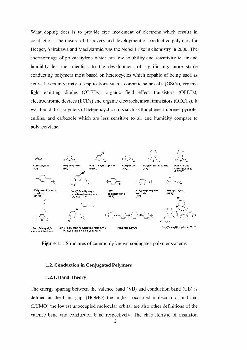
Figure 1.1: Structures of commonly known conjugated polymer systems .............. 2
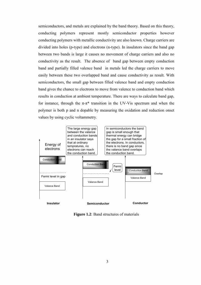
Figure 1.2: Band structures of materials .................................................................. 3
Figure 1.3: Charge carriers ...................................................................................... 4
Figure 1.4: Band Structure of the polymer with bipolaron states ............................ 5
Figure 1.5: Modification of band gap....................................................................... 7
Figure 1.6: Representative electron-transporting polymer semiconductors............. 9
Figure 1.7: Viologen redox states .......................................................................... 11
Figure 1.8: Illustrative example of electroactive conjugated conducting polymers
................................................................................................................................. 13
Figure 1.9: sRGB and CMYK color models .......................................................... 14
Figure 1.10: Literature examples of blue to transmissive switching polymers .... 15
Figure 1.11: Literature examples of green electrochromic polymers .................... 16
Figure 1.12: Literature examples of red to transmissive electrochromic copolymers
................................................................................................................................. 17
Figure 1.13: Tuning color by substituents .............................................................. 18
Figure 1.14: Illustrative example of electrochromic polymers. “Color swatches are
representations of thin films based on measured CIE 1931 Yxy color coordinates.
Key: 0 = neutral; I = intermediate; + = oxidized; - and -- = reduced” .................... 19
Figure 1.15: Electropolymerization mechanism .................................................... 23
Figure 1.16: Oxidative chemical polymerization. .................................................. 23
Figure 1.17: Suzuki coupling ................................................................................. 24
Figure 1.18: Stille coupling ................................................................................... 24
Figure 1.19: Yamamoto coupling........................................................................... 24
Figure 1.20: Knoevenagel condensation ................................................................ 25
Figure 1.21: Regioregular HT-P3ATs prepared using Ni-catalyzed Kumada
conditions: dppp = 1,2-bis(diphenylphosphino)propane ........................................ 25
Figure 1.22: Sonogashira coupling ........................................................................ 26
Figure 2.1: Synthesis of 2-decyl-1-tetradecylbromide ........................................... 29
Figure 2.2: Synthesis of N-(2-decyltetradecyl) phathalimide. ............................... 30
xviii
Figure 2.3: Synthesis of 2-decyl-1-tetradecylamine. ............................................. 31
Figure 2.4: Synthesis of PDI-2Br ........................................................................... 31
Figure 2.5: Synthesis of N,N’-bis(2-decyltetradecyl)-1,6-bibromo-3,4,9,10-
perylene diimide. ..................................................................................................... 32
Figure 2.6: Synthesis of tributyl(2,3-dihydrothieno[3,4-b][1,4]dioxin-5-
yl)stannane............................................................................................................... 33
Figure 2.7: Synthesis of 2,9-bis(2-decyltetradecyl)-5,12-bis(2,3-dihydrothieno[3,4-
b][1,4]dioxin-5-yl)anthrax [2,1,9-def:6,5,10-d'e'f']diisoquinoline-1,3,8,10(2H,9H)-
tetraone (PDI-EDOT) .............................................................................................. 34
Figure 2.8: Synthesis of diethyl 2,2-dipentadecylmalonate. .................................. 35
Figure 2.9: Synthesis of 2,2-sipentadecyl-1,3-propanediol. ................................... 35
Figure 2.10: Synthesis of 2,3,4,5-tetrabromothiophene. ........................................ 36
Figure 2.11: Synthesis of 3,4-dibromothiophene. .................................................. 37
Figure 2.12: Synthesis of 3,4-dimethoxythiophene. .............................................. 37
Figure 2.13: Synthesis of 3,3'-didodecyl-3,4-dihydro-2H-thieno[3,4-
b][1,4]dioxepine(ProDOT) ...................................................................................... 38
Figure 2.14: Synthesis of tributyl(3,3-diundecyl-3,4-dihydro-2H-thieno[3,4-
b][1,4]dioxepin-6-yl)stannane. ................................................................................ 39
Figure 2.15: Synthesis of (3,3-didecyl-3,4-dihydro-2H-thieno[3,4-b][1,4]dioxepin-
6-yl)trimethylstannane............................................................................................. 39
Figure 2.16: Synthesis of 5,8-dibromo-2,3-bis(4-((2-
octyldodecyl)oxy)phenyl)quinoxaline ..................................................................... 40
Figure 2.17: Synthesis of 5,8-bis(3,3-diundecyl-3,4-dihydro-2H-thieno[3,4-
b][1,4]dioxepin-6-yl)-2,3-bis(4-(dodecyloxy)phenyl)quinoxaline ......................... 41
Figure 2.18: Synthesis of 4,7-bis(3,3-didecyl-3,4-dihydro-2H-thieno[3,4-
b][1,4]dioxepin-6 yl)benzo[c][1,2,5]oxadiazole (BENZ-Pro-DOT) ....................... 42
Figure 3.1: Synthetic pathway of PDI-EDOT (12). ............................................... 45
Figure 3.2: Synthetic pathway of the central unit. ................................................. 47
Figure 3.3: Synthetic pathway of the central unit. ................................................. 47
Figure 3.4: Repeated scan polymerization of PDI-EDOT (WE: ITO, CE: Pt wire,
RE: Ag wire, 0.1 M TBAPF6/DCM/ACN 100 mV s-1, 10 cycles).......................... 49
Figure 3.5: Single scan cyclic voltammetry of PDI-EDOT (WE: ITO, CE: Pt wire,
RE: Ag wire, 0.1 M TBAPF6/DCM/ACN 100 mV s-1)........................................... 50
xix
Figure 3.6: Spectroelectrochemistry studies of PPDI-EDOT (-0.1 V to 1.4 V with
0.1 V increments). ................................................................................................... 51
Figure 3.7: Photographs of the PPDI-EDOT at its neutral and oxidized states. .... 51
Figure 3.8: Electrochromic switching and optical absorbance change of PPDI-
EDOT monitored at 402 nm (30 cycles). ................................................................ 52
Figure 3.9: Electrochromic switching and optical absorbance change of PPDI-
EDOT monitored at 492 nm (30 cycles). ................................................................ 53
Figure 3.10: Electrochromic switching and optical absorbance change of PPDI-
EDOT monitored at 1470 nm (30 cycles). .............................................................. 53
Figure 3.11: Repeated scan polymerization of BENZ-Pro-DOT (WE: ITO, CE: Pt
wire, RE: Ag wire, 0.1 M TBAPF6/DCM/ACN, 100 mV s-1, 10 cycles). ............. 54
Figure 3.12: n-Doped polymerization of BENZ-Pro-DOT (WE: ITO, CE: Pt wire,
RE: Ag wire, 0.1 M TBAPF6/DCM/ACN, 100 mV s-1) ......................................... 55
Figure 3.13: p-Doped polymerization of BENZ-Pro-DOT (WE: ITO, CE: Pt wire,
RE: Ag wire, 0.1 M TBAPF6/DCM/ACN, 100 mV s-1) ......................................... 56
Figure 3.14: Spectroelectrochemistry studies of PBENZ-Pro-DOT (-0.1 V to 1.4
V with 0.1 V increments). ....................................................................................... 56
Figure 3.15: Photographs of the PBENZ-Pro-DOT at its neutral and oxidized
states ........................................................................................................................ 57
Figure 3.16: Electrochromic switching and optical absorbance change of PBENZ-
Pro-DOT monitored at 400 nm (30 cycles)............................................................. 58
Figure 3.17: Electrochromic switching and optical absorbance change of PBENZ-
Pro-DOT monitored at 720 nm (30 cycles)............................................................. 59
Figure 3.18: Electrochromic switching and optical absorbance change of PBENZ-
Pro-DOT monitored at 1350 nm (30 cycles)........................................................... 59
Figure A.1.1: 1H-NMR spectrum 2-decyl-1-tetradecylbromide ............................ 69
Figure A.1.2: 13C-NMR spectrum of 2-decyl-1-tetradecylbromide ...................... 70
Figure A.2.1: 1H-NMR spectrum N-(2-decyltetradecyl)phathalimide ................... 71
Figure A.2.2: 13C-NMR spectrum of N-(2-decyltetradecyl)phathalimide ............. 72
Figure A.3.1: 1H-NMR spectrum 2-decyl-1-tetradecylamine ................................ 73
Figure A.3.2: 13C-NMR spectrum of 2-decyl-1-tetradecylamine ......................... 74
Figure A.4.1: 1H-NMR spectrum N,N’-bis(2-decyltetradecyl)-1,6-dibromo-
3,4,9,10-perylene diimide ....................................................................................... 75
xx
Figure A.5.1: 1H-NMR spectrum of tributyl(2,3-dihydrothieno[3,4-b][1,4]dioxin-
5-yl)stannane ........................................................................................................... 76
Figure A.5.2: 13C-NMR spectrum of tributyl(2,3-dihydrothieno[3,4-b][1,4]dioxin-
5-yl)stannane ........................................................................................................... 77
Figure A.6.1: 1H-NMR spectrum of PDI-e-Dot ..................................................... 78
Figure A.6.2: 13C-NMR spectrum of PDI-e-Dot .................................................... 79
Figure A.7.1: 1H-NMR spectrum diethyl 2,2-dipentadecylmalonate ..................... 80
Figure A.7.2: 13C-NMR spectrum diethyl of 2,2-dipentadecylmalonate ............... 81
Figure A.8.1: 1H-NMR spectrum of 2,2-dipentadecyl-1,3-propanediol ................. 82
Figure A.8.2: 13C-NMR spectrum of 2,2-dipentadecyl-1,3-propanediol ............... 83
Figure A.9.2: 13C-NMR spectrum of2,3,4,5-tetrabromothiophene ........................ 84
Figure A.10.1: 1H-NMR spectrum of 3,4-dibromothiophene ................................ 85
Figure A.10.2: 13C-NMR spectrum of 3,4-dibromothiophene ............................... 86
Figure A.11.1: 1H-NMR spectrum of 3,4-dimethoxythiophene............................. 87
Figure A.11.2: 13C-NMR spectrum of 3,4-dimethoxythiophene ........................... 88
Figure A.12.1: 1H-NMR spectrum of 3,3'-didodecyl-3,4-dihydro-2H-thieno[3,4-
b][1,4]dioxepine(ProDOT) ...................................................................................... 89
Figure A.12.2: 13C-NMR spectrum of 3,3'-didodecyl-3,4-dihydro-2H-thieno[3,4-
b][1,4]dioxepine(ProDOT) ...................................................................................... 90
Figure A.13.1: 1H-NMR spectrum of tributyl(3,3-diundecyl-3,4-dihydro-2H-
thieno[3,4-b][1,4]dioxepin-6-yl)stannane ............................................................... 91
Figure A.13.2: 13C-NMR spectrum of tributyl(3,3-diundecyl-3,4-dihydro-2H-
thieno[3,4-b][1,4]dioxepin-6-yl)stannane ............................................................... 92
Figure A.14.1: 1H-NMR (3,3-didecyl-3,4-dihydro-2H-thieno[3,4-b][1,4]dioxepin-
6-yl)trimethylstannane............................................................................................. 93
Figure A.14.2: 13C-NMR (3,3-didecyl-3,4-dihydro-2H-thieno[3,4-b][1,4]dioxepin-
6-yl)trimethylstannane............................................................................................. 94
Figure A.15.1: 1H-NMR spectrum of 5,8-dibromo-2,3-bis(4-((2-
octyldodecyl)oxy)phenyl)quinoxaline ..................................................................... 95
Figure A.15.2: 13C-NMR spectrum of 5,8-dibromo-2,3-bis(4-((2-
octyldodecyl)oxy)phenyl)quinoxaline ..................................................................... 96
Figure A.16.1: 1H-NMR spectrum of 5,8-bis(3,3-diundecyl-3,4-dihydro-2H-
thieno[3,4-b][1,4]dioxepin-6-yl)-2,3-bis(4-(dodecyloxy)phenyl)quinoxaline ........ 97
xxi
Figure A.16.2: 13C-NMR spectrum of 5,8-bis(3,3-diundecyl-3,4-dihydro-2H-
thieno[3,4-b][1,4]dioxepin-6-yl)-2,3-bis(4-(dodecyloxy)phenyl)quinoxaline ........ 98
Figure A.17.1: 1H-NMR spectrum of 4,7-bis(3,3-didecyl-3,4-dihydro-2H-
thieno[3,4-b][1,4]dioxepin-6-yl)benzo[c][1,2,5]oxadiazole FF .............................. 99
xxii
LIST OF ABBREVIATIONS
ACN Acetonitrile
BDT Benzo[1,2-b:4,5-b′]dithiophene
BHJ Bulk Heterojunction Cell
BTA Benzo[d][1,2,3]triazole
CHCl3 Chloroform
CIE Commission Internationale de l’Eclairage
CV Cyclic Voltammetry
D-A Donor-Acceptor
D-A-D Donor-Acceptor-Donor
DCM Dichloromethane
DMF Dimethyl Formamide
DMSO Dimethyl Sulfoxide
EDOT 3,4-Ethylenedioxythiophene
Eg Band Gap
Egec Electronic Band Gap
Egop Optical Band Gap
EtOH Ethanol
GPC Gel Permeation Chromatography
HRMS High Resolution Mass Spectrometer
xxiii
HOMO Highest Occupied Molecular Orbital
ITO Indium Tin Oxide”
I-V Current Density-Voltage
Jsc Short-Circuit Current Density
L, a, b Luminance, Hue, Saturation
LiClO4 Lithium Perchlorate
LUMO Lowest Unoccupied Molecular Orbital
n-BuLi n-Butyl Lithium
NaClO4 Sodium Perchlorate
NBS N-Bromosuccinimide
NHE Normal Hydrogen Electrode
NIR Near-Infrared
NMR Nuclear Magnetic Resonance Spectrometer
OSC Organic Solar Cell
PC71BM [6,6]-Phenyl C71 Butyric Acid Methyl Ester
PCE Power Conversion Efficiency
PSS Polystyrene Sulfonate
Pt Platinum
p-TSA p-Toluene Sulfonic Acid
TBAPF6 Tetrabutylammonium Hexafluorophosphate
THF Tetrahydrofuran
TLC Thin Layer Chromatography
TPD Thieno[3,4-c]pyrrole-4,6-dione

xxiv
VIS Visible
Voc Open-Circuit Voltage
1
CHAPTER 1
INTRODUCTION
1.1.Conjugated Polymers
A similar electrical and optical property has been demonstrated by the great number
of polymers that are being used commercially in our daily lives such as polyethylene,
polyvinyl chloride or poly(methyl methacrylate). They have no mobile charge
carriers and their lowest electronic transitions are mostly observed in UV region of
the spectrum. On the other hand, there exists a different class of polymers with
uniquely different characteristics. These materials with conjugated double bonds
along their main chain are semiconductors, or with strong doping even conductors.
During recent decades conjugated polymers have attracted an enormous amount of
interest among scientists owing to their processability with solution-based methods,
ease in modification of their band gap with structural changes, their low cost, and
their potential for realization of flexible devices. Polthiazyl was the first member of
synthetic conjugated polymers (inorganic) and this black powder materials were
found to be a superconductor at 2K [1]. It was Alan J. Heeger, Hideki Shirakawa and
Alan G. MacDiarmid were the leading scientist who brought conjugated carbon-
based polymers into the realm of electronics. They proved how a plastic can be a good
conductor of electricity in its oxidized and reduced states. The accidental use of the
great amount of Ziegler-Natta catalyst in the process of the synthesizing of
polyacetylene from methane resulted in a metal-like silvery black film [1]. The
outcome of this discovery was the extraordinarily high conductivity (103 S/cm) upon
doping with iodine vapor at room temperature Shirakawa et. al. later showed that the
trans polyacetylene, the thermodynamically stable form, shows higher conductivity
compared to cis form of the same material. [2]. π-conjugation is the main necessity
for a polymer to be conductive. The process of adding the electron deficient
chemicals such as halogens is called doping. Through doping, the conductivity of
the plastic can be increased up to 109 fold and can match the conductivity of metals.
2
What doping does is to provide free movement of electrons which results in
conduction. The reward of discovery and development of conductive polymers for
Heeger, Shirakawa and MacDiarmid was the Nobel Prize in chemistry in 2000. The
shortcomings of polyacetylene which are low solubility and sensitivity to air and
humidity led the scientists to the development of significantly more stable
conducting polymers most based on heterocycles which capable of being used as
active layers in variety of applications such as organic solar cells (OSCs), organic
light emitting diodes (OLEDs), organic field effect transistors (OFETs),
electrochromic devices (ECDs) and organic electrochemical transistors (OECTs). It
was found that polymers of hetereocyclic units such as thiophene, fluorene, pyrrole,
aniline, and carbazole which are less sensitive to air and humidity compare to
polyacetylene.
Figure 1.1: Structures of commonly known conjugated polymer systems
1.2. Conduction in Conjugated Polymers
1.2.1. Band Theory
The energy spacing between the valence band (VB) and conduction band (CB) is
defined as the band gap. (HOMO) the highest occupied molecular orbital and
(LUMO) the lowest unoccupied molecular orbital are also other definitions of the
valence band and conduction band respectively. The characteristic of insulator,
3
semiconductors, and metals are explained by the band theory. Based on this theory,
conducting polymers represent mostly semiconductor properties however
conducting polymers with metallic conductivity are also known. Charge carriers are
divided into holes (p-type) and electrons (n-type). In insulators since the band gap
between two bands is large it causes no movement of charge carriers and also no
conductivity as the result. The absence of “band gap between empty conduction
band and partially filled valence band” in metals led the charge carriers to move
easily between these two overlapped band and cause conductivity as result. With
semiconductors, the small gap between filled valence band and empty conduction
band gives the chance to electrons to move from valence to conduction band which
results in conduction at ambient temperature. There are ways to calculate band gap,
for instance, through the π-π* transition in the UV-Vis spectrum and when the
polymer is both p and n dopable by measuring the oxidation and reduction onset
values by using cyclic voltammetry.
Figure 1.2: Band structures of materials
4
1.2.2. Conduction in Conjugated Polymers
Although there are several techniques available for preparation of conducting
polymers such as photochemical, solid state and pyrolysis; the two broadly employed
methods for synthesizing conductive polymers are the chemical (coupling chemistry
and oxidative chemical polymerization) and electrochemical polymerizations [3].
The method of polymerization should be determined carefully towards synthesis of
a polymer with desired set of properties such conductivity, processability and
stability.
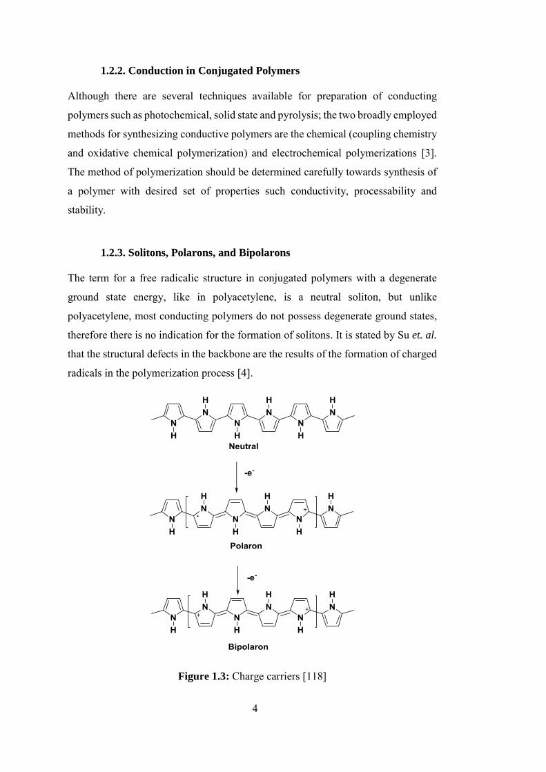
1.2.3. Solitons, Polarons, and Bipolarons
The term for a free radicalic structure in conjugated polymers with a degenerate
ground state energy, like in polyacetylene, is a neutral soliton, but unlike
polyacetylene, most conducting polymers do not possess degenerate ground states,
therefore there is no indication for the formation of solitons. It is stated by Su et. al.
that the structural defects in the backbone are the results of the formation of charged
radicals in the polymerization process [4].
Figure 1.3: Charge carriers [118]
5
When the polymer oxidized the energy of the orbital will be raised by removing
electrons. ‘Polaron’ is the radical resulted by the removal of one electron. Polarons
have both spin and charge [5, 6]. Through further exothermic chain oxidation
reactions, dications namely known as bipolarons will be formed [7]. In these
reactions, it is also possible for two polarons to be formed; however, due to the
electronic repulsion caused by two charges, bipolarons are thermodynamically more
stable.
1.2.4. Doping
Doping is the introduction of charge carriers to the polymer backbone through a
redox process. p-Doping is the removal of an electron from the polymer chain
whereas n-doping is the addition of an electron to the polymer chain. Since both
neutral and heavily doped states are diamagnetic in nature, there is no net spin
defined for them. Most heavily doped materials conduct electricity [6].
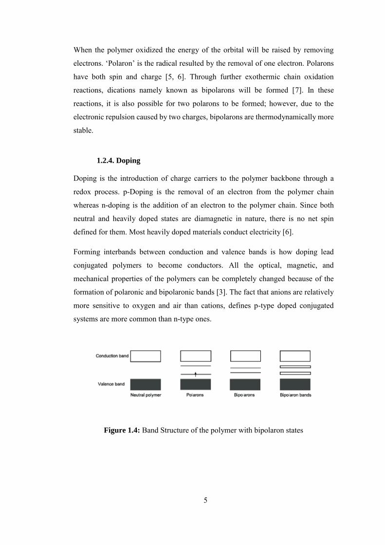
Forming interbands between conduction and valence bands is how doping lead
conjugated polymers to become conductors. All the optical, magnetic, and
mechanical properties of the polymers can be completely changed because of the
formation of polaronic and bipolaronic bands [3]. The fact that anions are relatively
more sensitive to oxygen and air than cations, defines p-type doped conjugated
systems are more common than n-type ones.
Figure 1.4: Band Structure of the polymer with bipolaron states
6
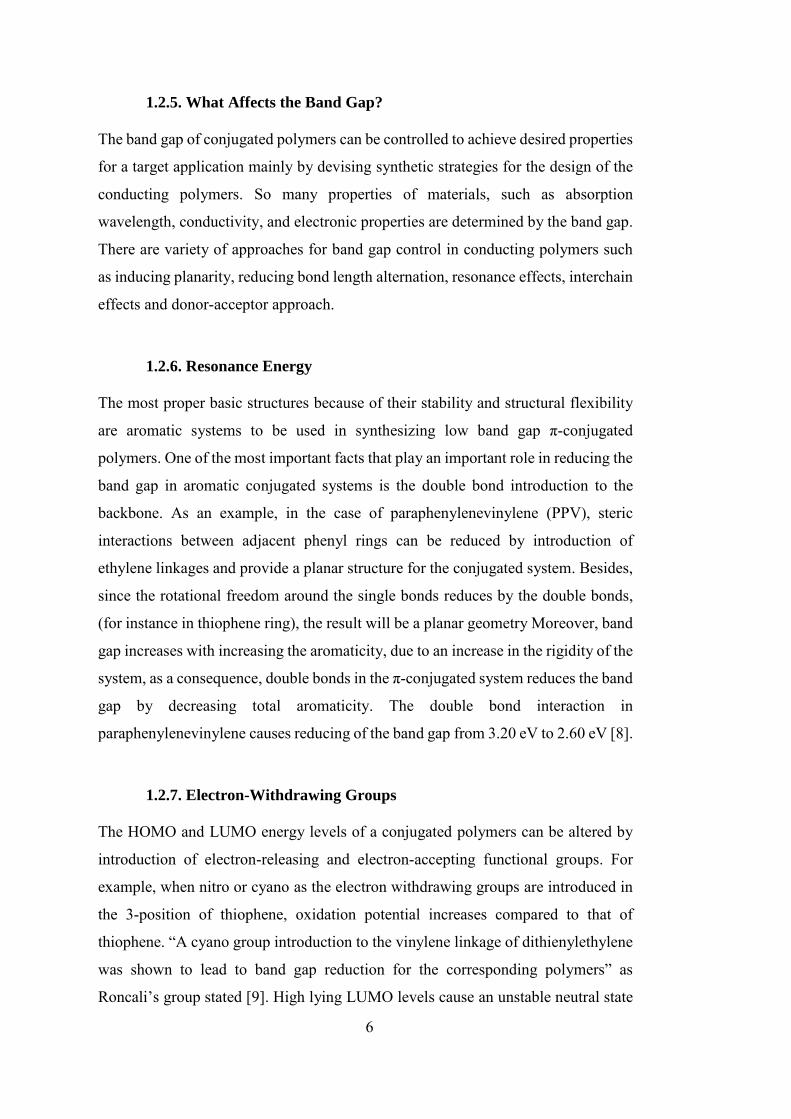
1.2.5. What Affects the Band Gap?
The band gap of conjugated polymers can be controlled to achieve desired properties
for a target application mainly by devising synthetic strategies for the design of the
conducting polymers. So many properties of materials, such as absorption
wavelength, conductivity, and electronic properties are determined by the band gap.
There are variety of approaches for band gap control in conducting polymers such
as inducing planarity, reducing bond length alternation, resonance effects, interchain
effects and donor-acceptor approach.
1.2.6. Resonance Energy
The most proper basic structures because of their stability and structural flexibility
are aromatic systems to be used in synthesizing low band gap π-conjugated
polymers. One of the most important facts that play an important role in reducing the
band gap in aromatic conjugated systems is the double bond introduction to the
backbone. As an example, in the case of paraphenylenevinylene (PPV), steric
interactions between adjacent phenyl rings can be reduced by introduction of
ethylene linkages and provide a planar structure for the conjugated system. Besides,
since the rotational freedom around the single bonds reduces by the double bonds,
(for instance in thiophene ring), the result will be a planar geometry Moreover, band
gap increases with increasing the aromaticity, due to an increase in the rigidity of the
system, as a consequence, double bonds in the π-conjugated system reduces the band
gap by decreasing total aromaticity. The double bond interaction in
paraphenylenevinylene causes reducing of the band gap from 3.20 eV to 2.60 eV [8].
1.2.7. Electron-Withdrawing Groups
The HOMO and LUMO energy levels of a conjugated polymers can be altered by
introduction of electron-releasing and electron-accepting functional groups. For
example, when nitro or cyano as the electron withdrawing groups are introduced in
the 3-position of thiophene, oxidation potential increases compared to that of
thiophene. “A cyano group introduction to the vinylene linkage of dithienylethylene
was shown to lead to band gap reduction for the corresponding polymers” as
Roncali’s group stated [9]. High lying LUMO levels cause an unstable neutral state
7
of the system, the effect of electron-withdrawing groups such as cyano is to decrease
the LUMO level and leads to stabilization of neutral state system [10]. Theoretical
studies offer that the increase in the quinoid character of the ground system can lower
the band gap, however, the drawback of this approach is that generally a major
increase is the oxidation potential which results in difficulties during electrochemical
or oxidative chemical polymerization methods.
1.2.8. Electron-donating Groups
The HOMO level increases by introducing the electron-donor groups in a conjugated
system which results in a reduced band gap. Studies show that the inductive effect
of alkyl groups can cause a decrease in oxidation potential of the materials [11]. In
case of linear alkyl chains, considering the length of the chain the increase in
lipophilic interactions between polymer chains can reduce the band gap [12, 13]. The
HOMO level increases effectively by introducing the strong electron donors such as
alkoxy groups. The formation of a highly strong donor in case of thiophene is the
result of oxygen attached to thiophene with an ethylene bridge as electron releasing
groups. The mentioned group can easily be polymerized through chemical or
electrochemical methods yielding a highly-conductive polymer such shows
significantly lower band gap compared to polythiophene [14, 15].
Figure 1.5: Modification of band gap
8
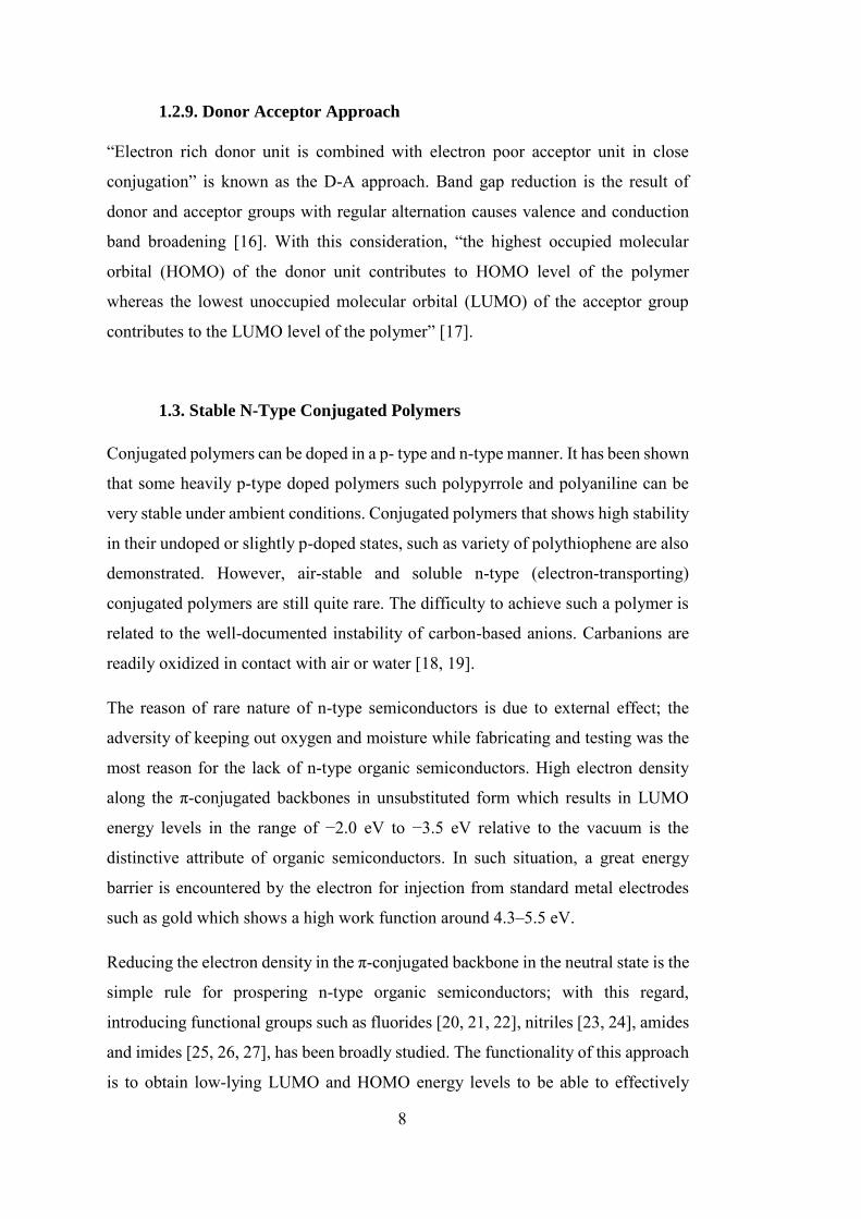
1.2.9. Donor Acceptor Approach
“Electron rich donor unit is combined with electron poor acceptor unit in close
conjugation” is known as the D-A approach. Band gap reduction is the result of
donor and acceptor groups with regular alternation causes valence and conduction
band broadening [16]. With this consideration, “the highest occupied molecular
orbital (HOMO) of the donor unit contributes to HOMO level of the polymer
whereas the lowest unoccupied molecular orbital (LUMO) of the acceptor group
contributes to the LUMO level of the polymer” [17].
1.3. Stable N-Type Conjugated Polymers
Conjugated polymers can be doped in a p- type and n-type manner. It has been shown
that some heavily p-type doped polymers such polypyrrole and polyaniline can be
very stable under ambient conditions. Conjugated polymers that shows high stability
in their undoped or slightly p-doped states, such as variety of polythiophene are also
demonstrated. However, air-stable and soluble n-type (electron-transporting)
conjugated polymers are still quite rare. The difficulty to achieve such a polymer is
related to the well-documented instability of carbon-based anions. Carbanions are
readily oxidized in contact with air or water [18, 19].
The reason of rare nature of n-type semiconductors is due to external effect; the
adversity of keeping out oxygen and moisture while fabricating and testing was the
most reason for the lack of n-type organic semiconductors. High electron density
along the π-conjugated backbones in unsubstituted form which results in LUMO
energy levels in the range of −2.0 eV to −3.5 eV relative to the vacuum is the
distinctive attribute of organic semiconductors. In such situation, a great energy
barrier is encountered by the electron for injection from standard metal electrodes
such as gold which shows a high work function around 4.3–5.5 eV.
Reducing the electron density in the π-conjugated backbone in the neutral state is the
simple rule for prospering n-type organic semiconductors; with this regard,
introducing functional groups such as fluorides [20, 21, 22], nitriles [23, 24], amides
and imides [25, 26, 27], has been broadly studied. The functionality of this approach
is to obtain low-lying LUMO and HOMO energy levels to be able to effectively
9
inject electrons and, stabilize the molecules with low reorganization energy. The
LUMO energy level lower than –3 eV is the energy level needed for the efficient
electron injection. Considering the fact that anionic form is less sensitive to air which
results in higher stability, the preferred LUMO energy level for an n-type material is
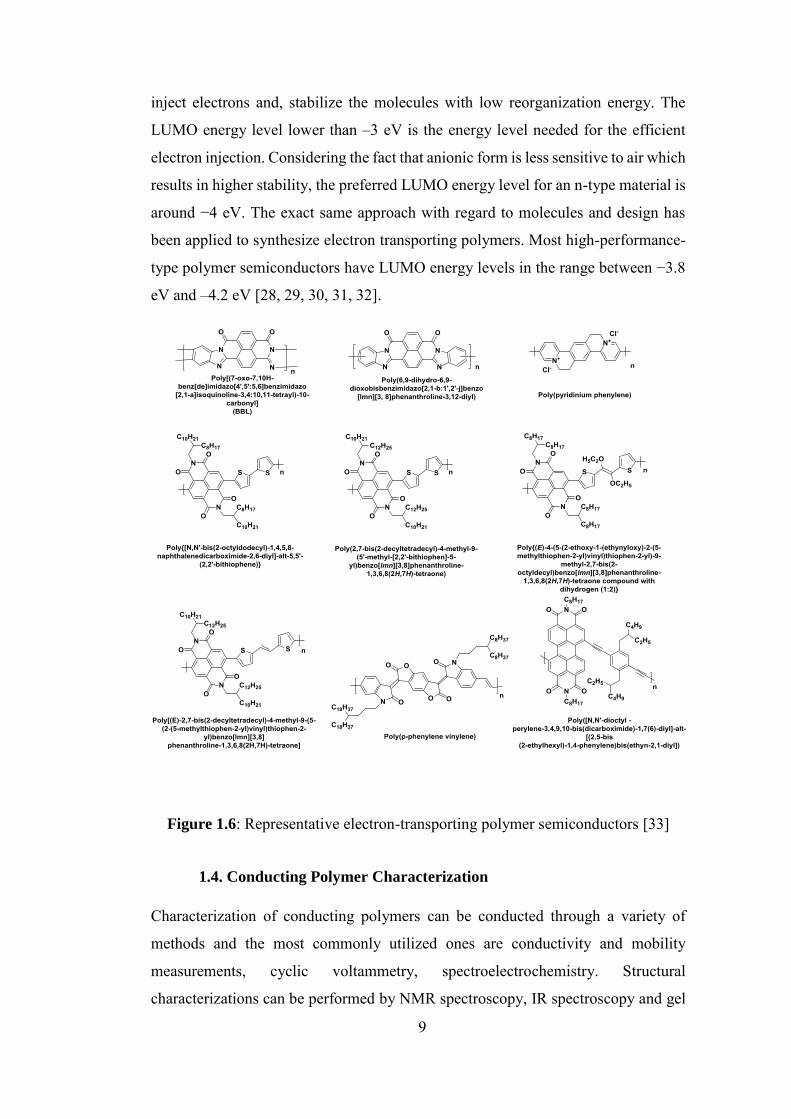
around −4 eV. The exact same approach with regard to molecules and design has
been applied to synthesize electron transporting polymers. Most high-performance-
type polymer semiconductors have LUMO energy levels in the range between −3.8
eV and –4.2 eV [28, 29, 30, 31, 32].
Figure 1.6: Representative electron-transporting polymer semiconductors [33]
1.4. Conducting Polymer Characterization
Characterization of conducting polymers can be conducted through a variety of
methods and the most commonly utilized ones are conductivity and mobility
measurements, cyclic voltammetry, spectroelectrochemistry. Structural
characterizations can be performed by NMR spectroscopy, IR spectroscopy and gel
10
permeation chromatography. The detection of the redox properties of polymers is
mainly studied via cyclic voltammetry. In spectroelectrochemistry, optical properties
of the materials are evaluated as a function of applied potential and a variety of
valuable information such as the band gap (Eg), absorption maxima (λmax), polaron
and bipolaron characteristics can be deduced. In kinetic studies, stepping repeated
potential between the neutral and oxidized states reveals the percent transmittance
changes and the time required for the switching these states. The number average
molecular weight, weight average molecular weight, and polydispersity index of the
polymer are the properties determined by gel permeation chromatography. Polymer
formation information can also be studied by 1H NMR spectra. Also, the idea of the
copolymer ratio for random copolymers can be provided by 1H NMR spectroscopy.
1.4.1. Chromism
Chromism is the reversible color change of materials upon external stimulus.
Different types of the chromism includes thermochromism, piezochromism,
solvatochromism, halochromism, and electrochromism.
1.4.2. Electrochromism
Electrochromism can be broadly defined as the reversible optical changes occur in a
polymer film upon applied external potential. The color change can occur between
two colored states or one colored and one highly transmissive state. More than two
colors can also be observed which is named as multichromism [34].
Electrochromism was initially observed in thin films of WO3 and MoO3 in late sixties
[35]. The potential of the electrochromic materials to be used in optical devices, not
only made them so popular but also a new gate to the development of new materials.
Metal oxides, viologens, metal hexacyanometallates, metal coordination complexes,
and conjugated conducting polymers are the different classes for electrochromic
materials [36]. The reason that made the conducting polymers a good choice for the
construction of electrochromic devices is the fact that their optical properties can be
easily tuned, they are low cost, flexible devices can be generated and polymers
generally have good UV stability and reasonable operation temperature range. The
important required parameters for electrochromic devices made from the polymers
11
are high coloration efficiency, good stability, high optical contrast, optical memory
and short response time. The most important fact to meet all these parameters at the
same time is the molecular design of these materials. Among variety of possible
application areas, car rear view mirrors, protective eyewear, and smart windows are
the ones that utilization of electrochromic devices are commonly envisioned [37,
38].
1.4.2.1. Electrochromic Material Types
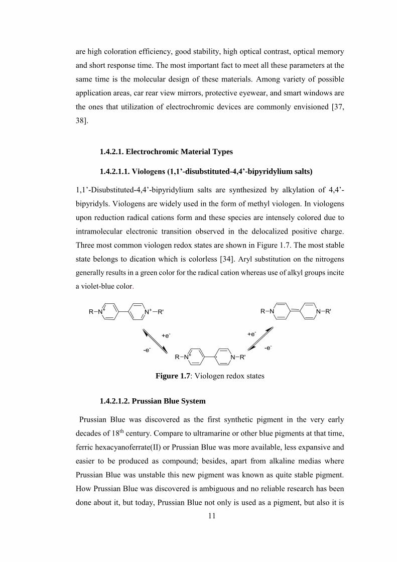
1.4.2.1.1. Viologens (1,1’-disubstituted-4,4’-bipyridylium salts)
1,1’-Disubstituted-4,4’-bipyridylium salts are synthesized by alkylation of 4,4’-
bipyridyls. Viologens are widely used in the form of methyl viologen. In viologens
upon reduction radical cations form and these species are intensely colored due to
intramolecular electronic transition observed in the delocalized positive charge.
Three most common viologen redox states are shown in Figure 1.7. The most stable
state belongs to dication which is colorless [34]. Aryl substitution on the nitrogens
generally results in a green color for the radical cation whereas use of alkyl groups incite
a violet-blue color.
Figure 1.7: Viologen redox states
1.4.2.1.2. Prussian Blue System
“Prussian Blue was discovered as the first synthetic pigment in the very early
decades of 18th century. Compare to ultramarine or other blue pigments at that time,
ferric hexacyanoferrate(II) or Prussian Blue was more available, less expansive and
easier to be produced as compound; besides, apart from alkaline medias where
Prussian Blue was unstable this new pigment was known as quite stable pigment.
How Prussian Blue was discovered is ambiguous and no reliable research has been
done about it, but today, Prussian Blue not only is used as a pigment, but also it is
12
used in other fields of applications such as electrochromic and poison antidotes
sensors. [39].
1.4.2.1.3. Metal Oxides
Cerium oxide, chromium oxide, cobalt oxide, iridium oxide, iron oxide, manganese
oxide, molybdenium oxide, nickel oxide, palladium oxide, ruthenium oxide,
tungsten oxide and vanadium oxide are the metal oxides which represent
electrochromic properties. [40]. the oxides of tungsten, molybdenium, nickel and
iridium has shown the most intense color change among all metal oxides used as
metallic electrochromic. A severe electronic absorption band upon reduction is
revealed by the transparent thin films of those metal oxides. Tungsten trioxide, WO3,
with a high band gap is known as the most popular electrochromic material. In a
study done by Berzelius in 1815 it was shown that through the reduction of pure
tungsten trioxide under hydrogen the color will change [41].“A similar experiment
was also done by Wöhler. In 1824, he used sodium to show the color change of WO3
a through reduction [42]. Tungsten trioxide is colorless or presenting a very pale
yellow in its oxidized form, it has the oxidized state of six (WVI) in contrast with
the fact that a deep blue color is formed by WV sites upon electrochemical reduction.
As more examples of electrochromic materials Molybdenium and vanadium oxides
can be mentioned [43, 44].
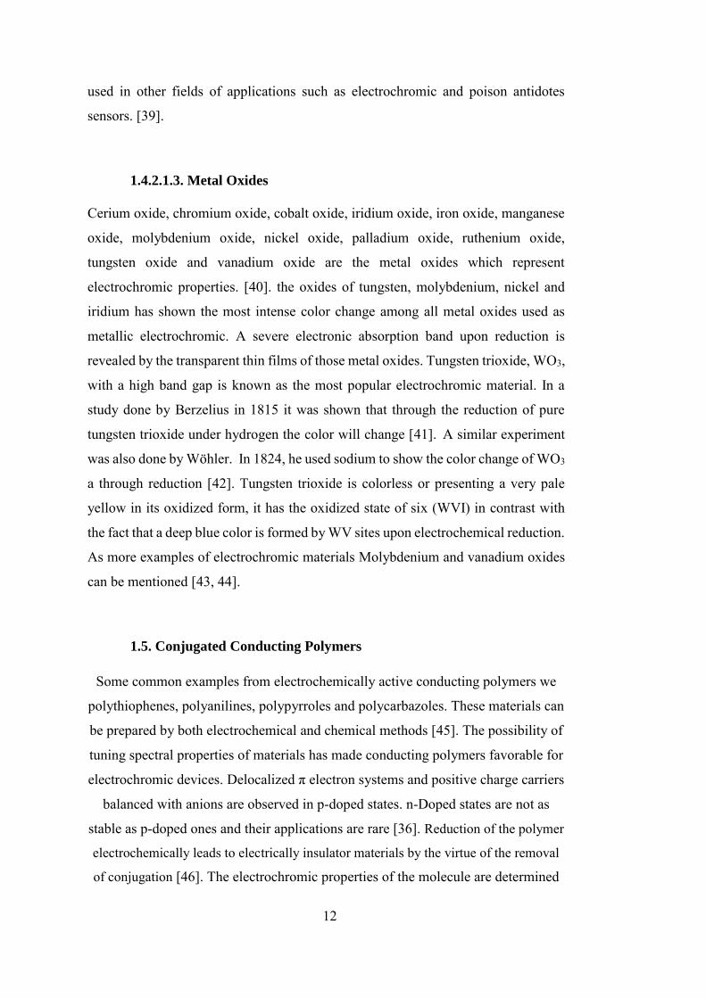
1.5. Conjugated Conducting Polymers
Some common examples from electrochemically active conducting polymers we
polythiophenes, polyanilines, polypyrroles and polycarbazoles. These materials can
be prepared by both electrochemical and chemical methods [45]. The possibility of
tuning spectral properties of materials has made conducting polymers favorable for
electrochromic devices. Delocalized π electron systems and positive charge carriers
balanced with anions are observed in p-doped states. n-Doped states are not as
stable as p-doped ones and their applications are rare [36]. Reduction of the polymer
electrochemically leads to electrically insulator materials by the virtue of the removal
of conjugation [46]. The electrochromic properties of the molecule are determined
13
by the band gap in the neutral state. Almost all of the polymers are colored in their
undoped form. If the band gap of materials is large (higher than 3 eV) no color in
the undoped form will be revealed, but in their doped form, they absorb visible
region of the light. Considering the fact that materials with moderate band gaps (1.7-
1.9 eV ) absorb in their neutral form, whereas absorption is really weak in the visible
region and free charge carriers are shifted to near IR region in the doped form.
Materials with smaller band gaps can show a variety of different colors. The certain
aromatic molecules which have initially been introduced at the beginning of this
paragraph are commonly benefited from an evenly distributed electron density,
which makes them resonance-stabilized from this electron delocalization. Five
membered rings with one heteroatom substitutions are one class of these
molecules. For example, thiophene (with a sulfur substitution), pyrrole (nitrogen
substitution) and furan (oxygen substitution). The other class based on six-
membered rings fused with five-membered ones (such as carbazole, azulene, and
indole), with various substitutions. Aniline is also another member of this class.
Chemical or electrochemical oxidation of these substances produces electroactive
conjugated conductingapolymers.
Figure 1.8: Illustrative example of electroactive conjugated conducting polymers
[47]
14
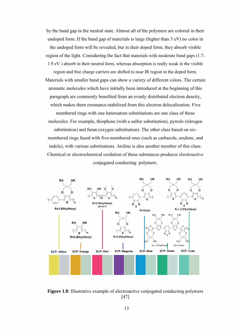
1.6. Utilized Color Models for Simple Electrochromic Display Devices
One of the forefront topics in material researches these days is non-emissive display
technologies utilizing electrochromic materials. Inexpensive printing techniques,
fabrication of the large area devices and having the ability to be viewed in a wide
variety of lighting conditions are the attractive benefits of electrochromic devices.
Materials that can exhibit three primary colors are utilized in electrochromic
displays. These materials can be employed to create full-colour displays through the
control of the contribution of each primary color. Towards realization of a simple
electrochromics based display device such as an e-paper, polymer that shows intense
RGB and/or CMYK colors in their reduced state that switches to a highly
transmissive oxidized state are required [48].
Figure 1.9: sRGB and CMYK color models [48]
1.6.1. Standard Red-Green-Blue (sRGB) Color Space
The trichromatic model of RGB is based on the additive primary colors of red (R),
green (G) and blue (B) [49,50]. RGB model is mainly used in display of images in
electronic systems, because the RGB model correlate with most closely to the
sensors of colored light. To come up with a color formation in the RGB model; the
three components of the light must be superimposed and emit from a black screen or
being reflected from a white screen. Throughout mixing a combination of different
components with different intensities the complete color scheme can be achieved.
The color black, as the darkest color, would be the result of the zero intensity and in
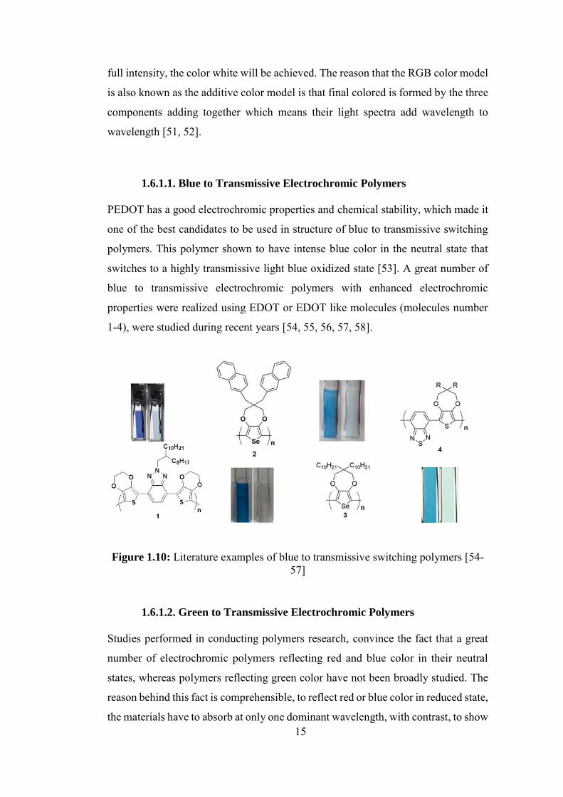
15
full intensity, the color white will be achieved. The reason that the RGB color model
is also known as the additive color model is that final colored is formed by the three
components adding together which means their light spectra add wavelength to
wavelength [51, 52].
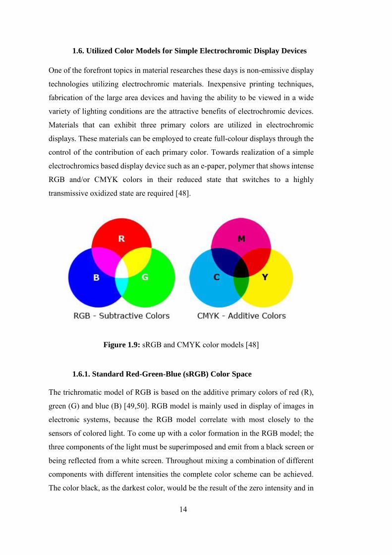
1.6.1.1. Blue to Transmissive Electrochromic Polymers
PEDOT has a good electrochromic properties and chemical stability, which made it
one of the best candidates to be used in structure of blue to transmissive switching
polymers. This polymer shown to have intense blue color in the neutral state that
switches to a highly transmissive light blue oxidized state [53]. A great number of
blue to transmissive electrochromic polymers with enhanced electrochromic
properties were realized using EDOT or EDOT like molecules (molecules number
1-4), were studied during recent years [54, 55, 56, 57, 58].
Figure 1.10: Literature examples of blue to transmissive switching polymers [54-57]
1.6.1.2. Green to Transmissive Electrochromic Polymers
Studies performed in conducting polymers research, convince the fact that a great
number of electrochromic polymers reflecting red and blue color in their neutral
states, whereas polymers reflecting green color have not been broadly studied. The
reason behind this fact is comprehensible, to reflect red or blue color in reduced state,
the materials have to absorb at only one dominant wavelength, with contrast, to show
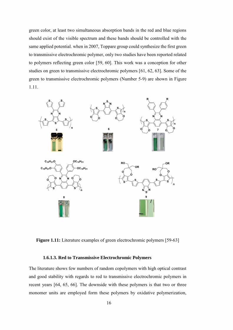
16
green color, at least two simultaneous absorption bands in the red and blue regions
should exist of the visible spectrum and these bands should be controlled with the
same applied potential. when in 2007, Toppare group could synthesize the first green
to transmissive electrochromic polymer, only two studies have been reported related
to polymers reflecting green color [59, 60]. This work was a conception for other
studies on green to transmissive electrochromic polymers [61, 62, 63]. Some of the
green to transmissive electrochromic polymers (Number 5-9) are shown in Figure
1.11.
Figure 1.11: Literature examples of green electrochromic polymers [59-63]
1.6.1.3. Red to Transmissive Electrochromic Polymers
The literature shows few numbers of random copolymers with high optical contrast
and good stability with regards to red to transmissive electrochromic polymers in
recent years [64, 65, 66]. The downside with these polymers is that two or three
monomer units are employed form these polymers by oxidative polymerization,
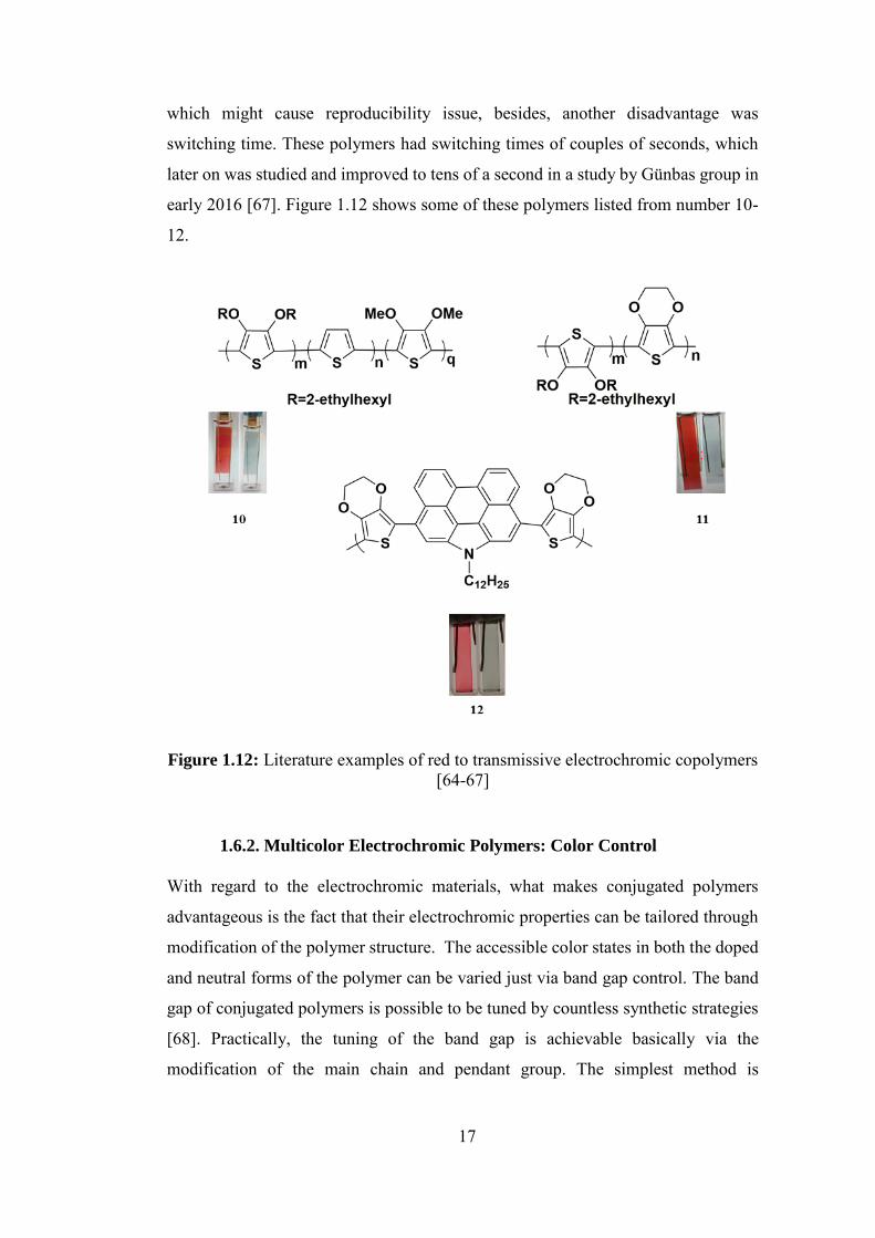
17
which might cause reproducibility issue, besides, another disadvantage was
switching time. These polymers had switching times of couples of seconds, which
later on was studied and improved to tens of a second in a study by Günbas group in
early 2016 [67]. Figure 1.12 shows some of these polymers listed from number 10-
12.
Figure 1.12: Literature examples of red to transmissive electrochromic copolymers [64-67]
1.6.2. Multicolor Electrochromic Polymers: Color Control
With regard to the electrochromic materials, what makes conjugated polymers
advantageous is the fact that their electrochromic properties can be tailored through
modification of the polymer structure. The accessible color states in both the doped
and neutral forms of the polymer can be varied just via band gap control. The band
gap of conjugated polymers is possible to be tuned by countless synthetic strategies
[68]. Practically, the tuning of the band gap is achievable basically via the
modification of the main chain and pendant group. The simplest method is
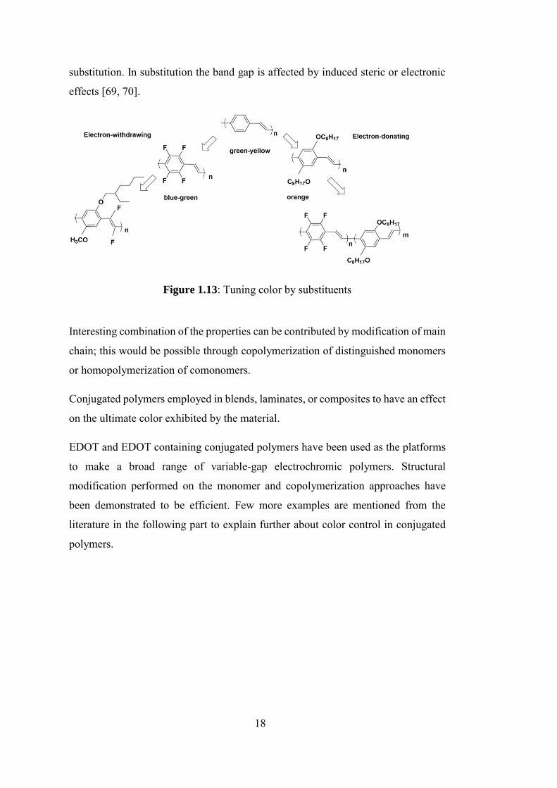
18
substitution. In substitution the band gap is affected by induced steric or electronic
effects [69, 70].
Figure 1.13: Tuning color by substituents
Interesting combination of the properties can be contributed by modification of main
chain; this would be possible through copolymerization of distinguished monomers
or homopolymerization of comonomers.
Conjugated polymers employed in blends, laminates, or composites to have an effect
on the ultimate color exhibited by the material.
EDOT and EDOT containing conjugated polymers have been used as the platforms
to make a broad range of variable-gap electrochromic polymers. Structural
modification performed on the monomer and copolymerization approaches have
been demonstrated to be efficient. Few more examples are mentioned from the
literature in the following part to explain further about color control in conjugated
polymers.
19
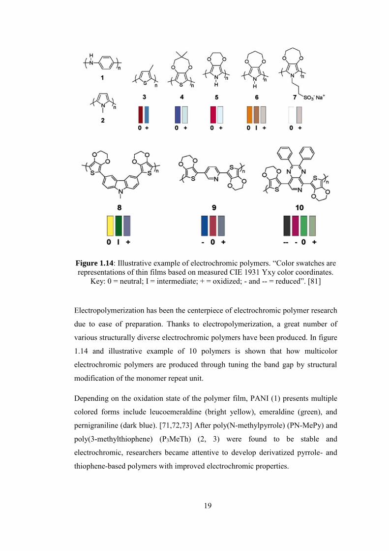
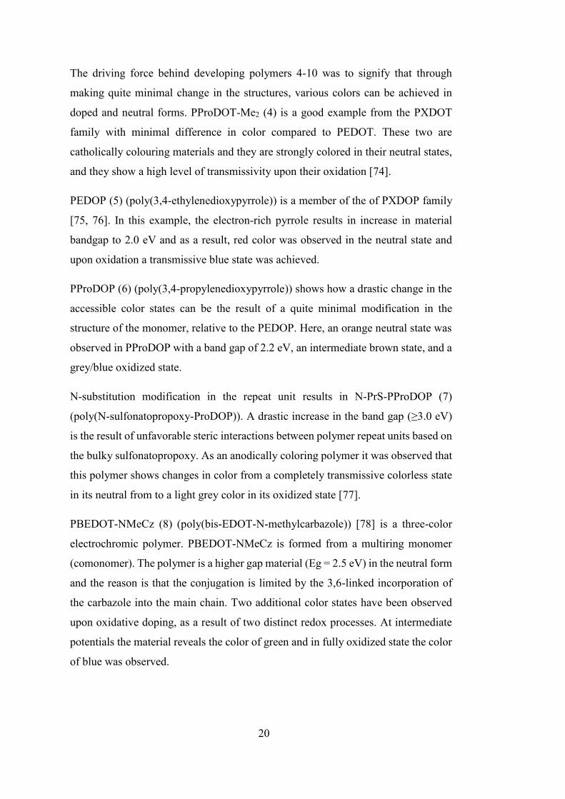
Figure 1.14: Illustrative example of electrochromic polymers. “Color swatches are representations of thin films based on measured CIE 1931 Yxy color coordinates.
Key: 0 = neutral; I = intermediate; + = oxidized; - and -- = reduced”. [81]
Electropolymerization has been the centerpiece of electrochromic polymer research
due to ease of preparation. Thanks to electropolymerization, a great number of
various structurally diverse electrochromic polymers have been produced. In figure
1.14 and illustrative example of 10 polymers is shown that how multicolor
electrochromic polymers are produced through tuning the band gap by structural
modification of the monomer repeat unit.
Depending on the oxidation state of the polymer film, PANI (1) presents multiple
colored forms include leucoemeraldine (bright yellow), emeraldine (green), and
pernigraniline (dark blue). [71,72,73] After poly(N-methylpyrrole) (PN-MePy) and
poly(3-methylthiophene) (P3MeTh) (2, 3) were found to be stable and
electrochromic, researchers became attentive to develop derivatized pyrrole- and
thiophene-based polymers with improved electrochromic properties.
20
The driving force behind developing polymers 4-10 was to signify that through
making quite minimal change in the structures, various colors can be achieved in
doped and neutral forms. PProDOT-Me2 (4) is a good example from the PXDOT
family with minimal difference in color compared to PEDOT. These two are
catholically colouring materials and they are strongly colored in their neutral states,
and they show a high level of transmissivity upon their oxidation [74].
PEDOP (5) (poly(3,4-ethylenedioxypyrrole)) is a member of the of PXDOP family
[75, 76]. In this example, the electron-rich pyrrole results in increase in material
bandgap to 2.0 eV and as a result, red color was observed in the neutral state and
upon oxidation a transmissive blue state was achieved.
PProDOP (6) (poly(3,4-propylenedioxypyrrole)) shows how a drastic change in the
accessible color states can be the result of a quite minimal modification in the
structure of the monomer, relative to the PEDOP. Here, an orange neutral state was
observed in PProDOP with a band gap of 2.2 eV, an intermediate brown state, and a
grey/blue oxidized state.
N-substitution modification in the repeat unit results in N-PrS-PProDOP (7)
(poly(N-sulfonatopropoxy-ProDOP)). A drastic increase in the band gap (≥3.0 eV)
is the result of unfavorable steric interactions between polymer repeat units based on
the bulky sulfonatopropoxy. As an anodically coloring polymer it was observed that
this polymer shows changes in color from a completely transmissive colorless state
in its neutral from to a light grey color in its oxidized state [77].
PBEDOT-NMeCz (8) (poly(bis-EDOT-N-methylcarbazole)) [78] is a three-color
electrochromic polymer. PBEDOT-NMeCz is formed from a multiring monomer
(comonomer). The polymer is a higher gap material (Eg = 2.5 eV) in the neutral form
and the reason is that the conjugation is limited by the 3,6-linked incorporation of
the carbazole into the main chain. Two additional color states have been observed
upon oxidative doping, as a result of two distinct redox processes. At intermediate
potentials the material reveals the color of green and in fully oxidized state the color
of blue was observed.
21
Other examples of multichromic polymers are PBEDOT-Pyr (9) and PBEDOT-
PyrPyr (10) [79, 80]. In their case, the donor-acceptor conjugated backbone resulted
in materials with low band gaps and both materials were shown to be both p- and n-
type dopable. The band gap for PBEDOTPyr was observed at 1.9 eV since the
electron withdrawing capacity of pyridine as an acceptor is weak. The polymer
shows three colors as a result of three distinct redox states. For PBEDOT-PyrPyr,
two n-doped states, a neutral state and a p-doped state are the result of the
significantly lower bandgap polymer (1.2 eV) due to pyridopyrazine unit serving as
a stronger acceptor compared to pyridine [81].
1.7. Polymerization Methods
The main polymerization techniques are listed in the following:
❖ electrochemical polymerization;
❖ photochemical polymerization;
❖ metathesis polymerization;
❖ solid-state polymerization;
❖ chemical polymerization;
❖ inclusion polymerization;
❖ plasma polymerization [82]
Among all the mentioned techniques, electrochemical and chemical polymerization
are the most favorable methods both in academia and industry [83].
1.7.1. Electropolymerization
To synthesize a conjugated polymer electrochemically a suporting electrolyte in an
inert organic solvent is needed. Irreversible oxidation and irreversible reduction are
respectively proceeded by anodic and cathodic polymerization. Having a tendency
for oxidation, anodic polymerization is used to synthesize homopolymers of electron
rich units such as pyrrole [7]. One of the advantageous of the electropolymerization
is that there is no requirement for further purification. In electropolymerization the
properties of the polymer are severely affected by the concentration of monomer,
22
solvent and electrolyte types, and electrodes. Other advantageous of
electropolymerization can also be mentioned as morphology, conductivity upon
applied potential, ease of production of an electrochemically active conductive
polymer film and control of film thickness, scan rate and time [84]. The anodes can
be used in electropolymerization can be listed as platinum, gold, glassy carbon, and
indium–tin oxide (ITO) coated glass. Electropolymerization is carried out
potentiostatically or galvanostatically. Potentiostatic (constant potential) or
galvanostatic (constant current) methods are the two ways for the
electropolymerization to be achieved. Since these techniques are easier to describe
quantitatively, they have been broadly utilized to investigate the nucleation
mechanism and the macroscopic growth. Potentiodynamic techniques such as cyclic
voltammetry correlate with a repetitive triangular potential waveform applied at the
surface of the electrode. The last method has been chiefly used to acquire qualitative
data about the redox processes engaged in the early stages of the polymerization
reaction, and to examine the electrochemical behavior of the polymer film after
electrodeposition. [85]. An appropriate solvent will be chosen and the monomer is
dissolved in it. Care must have taken to choose the solvent and electrolyte; solvent
and electrolyte should be stable at the oxidation potential of the monomer. The
solvents of choice for electropolymerization are acetonitrile and propylene carbonate
due to their high relative dielectric permittivity and large potential range. After the
monomer initially oxidized the radical cation will be formed. Then, through the reaction
of radical cation with other monomers present in solution a neutral dimer will be formed;
this happens by losing of another electron and two protons. With regard to form
oligomers, the oxidized radical cations react with monomers until the polymer is formed
[86, 87]. At the same time, the polymer is also doped while it is synthesized
electrochemically. Because of extended conjugation in the system the oxidation
potential of the polymer is lower than that of the monomers.
23
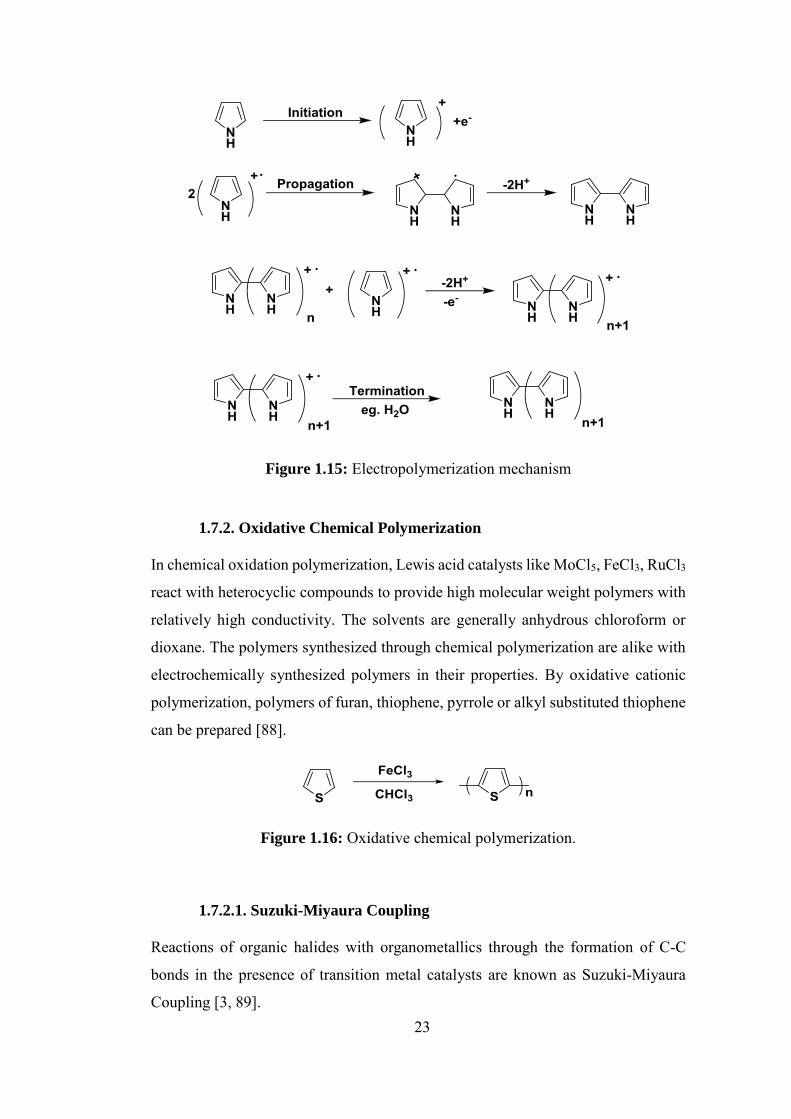
Figure 1.15: Electropolymerization mechanism
1.7.2. Oxidative Chemical Polymerization
In chemical oxidation polymerization, Lewis acid catalysts like MoCl5, FeCl3, RuCl3
react with heterocyclic compounds to provide high molecular weight polymers with
relatively high conductivity. The solvents are generally anhydrous chloroform or
dioxane. The polymers synthesized through chemical polymerization are alike with
electrochemically synthesized polymers in their properties. By oxidative cationic
polymerization, polymers of furan, thiophene, pyrrole or alkyl substituted thiophene
can be prepared [88].
Figure 1.16: Oxidative chemical polymerization.
1.7.2.1. Suzuki-Miyaura Coupling
Reactions of organic halides with organometallics through the formation of C-C
bonds in the presence of transition metal catalysts are known as Suzuki-Miyaura
Coupling [3, 89].
24
Figure 1.17: Suzuki coupling [90]
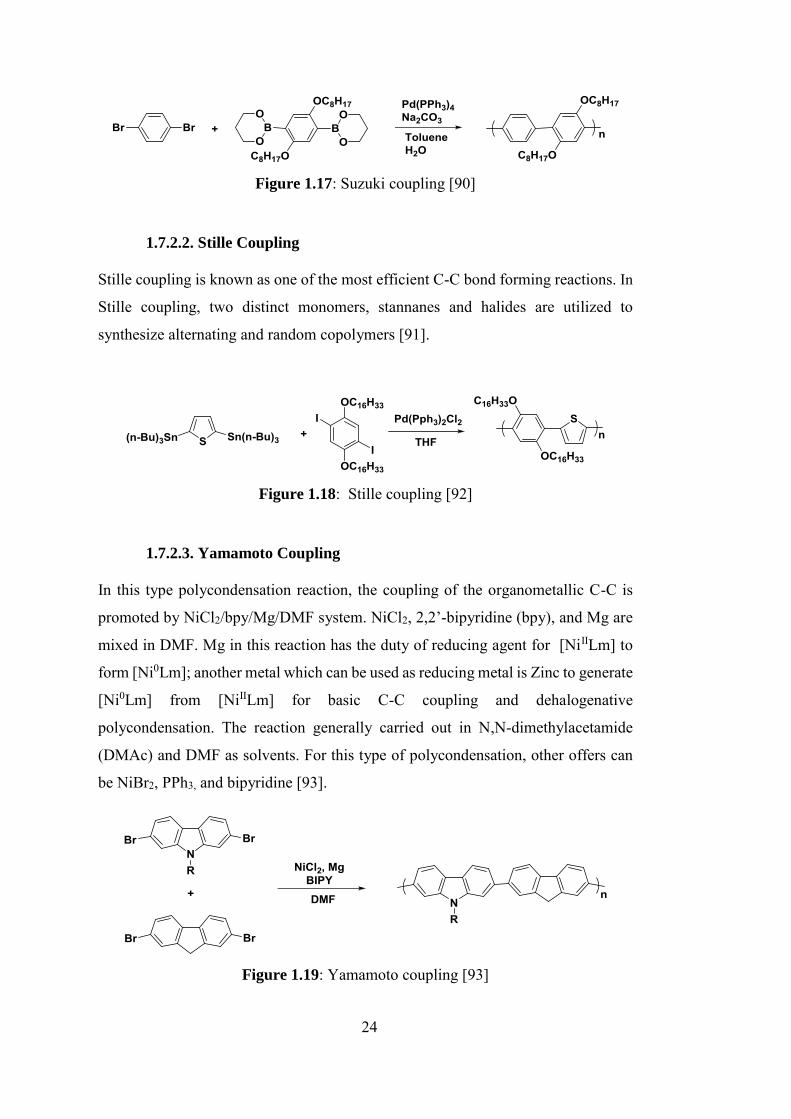
1.7.2.2. Stille Coupling
Stille coupling is known as one of the most efficient C-C bond forming reactions. In
Stille coupling, two distinct monomers, stannanes and halides are utilized to
synthesize alternating and random copolymers [91].
Figure 1.18: Stille coupling [92]
1.7.2.3. Yamamoto Coupling
In this type polycondensation reaction, the coupling of the organometallic C-C is
promoted by NiCl2/bpy/Mg/DMF system. NiCl2, 2,2’-bipyridine (bpy), and Mg are
mixed in DMF. Mg in this reaction has the duty of reducing agent for [NiIILm] to
form [Ni0Lm]; another metal which can be used as reducing metal is Zinc to generate
[Ni0Lm] from [NiIILm] for basic C-C coupling and dehalogenative
polycondensation. The reaction generally carried out in N,N-dimethylacetamide
(DMAc) and DMF as solvents. For this type of polycondensation, other offers can
be NiBr2, PPh3, and bipyridine [93].
Figure 1.19: Yamamoto coupling [93]
25
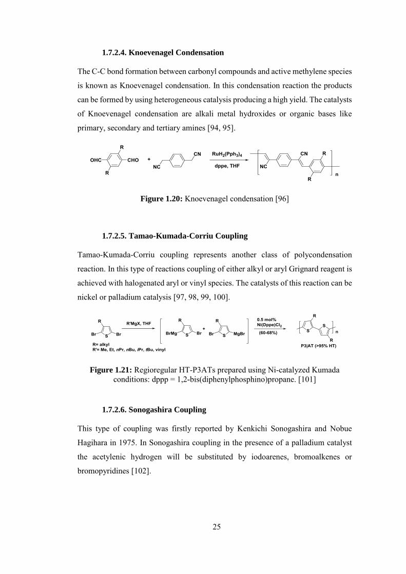
1.7.2.4. Knoevenagel Condensation
The C-C bond formation between carbonyl compounds and active methylene species
is known as Knoevenagel condensation. In this condensation reaction the products
can be formed by using heterogeneous catalysis producing a high yield. The catalysts
of Knoevenagel condensation are alkali metal hydroxides or organic bases like
primary, secondary and tertiary amines [94, 95].
Figure 1.20: Knoevenagel condensation [96]
1.7.2.5. Tamao-Kumada-Corriu Coupling
Tamao-Kumada-Corriu coupling represents another class of polycondensation
reaction. In this type of reactions coupling of either alkyl or aryl Grignard reagent is
achieved with halogenated aryl or vinyl species. The catalysts of this reaction can be
nickel or palladium catalysis [97, 98, 99, 100].
Figure 1.21: Regioregular HT-P3ATs prepared using Ni-catalyzed Kumada conditions: dppp = 1,2-bis(diphenylphosphino)propane. [101]
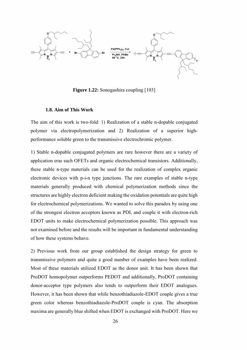
1.7.2.6. Sonogashira Coupling
This type of coupling was firstly reported by Kenkichi Sonogashira and Nobue
Hagihara in 1975. In Sonogashira coupling in the presence of a palladium catalyst
the acetylenic hydrogen will be substituted by iodoarenes, bromoalkenes or
bromopyridines [102].
26
Figure 1.22: Sonogashira coupling [103]
1.8. Aim of This Work
The aim of this work is two-fold: 1) Realization of a stable n-dopable conjugated
polymer via electropolymerization and 2) Realization of a superior high-
performance soluble green to the transmissive electrochromic polymer.
1) Stable n-dopable conjugated polymers are rare however there are a variety of
application eras such OFETs and organic electrochemical transistors. Additionally,
these stable n-type materials can be used for the realization of complex organic
electronic devices with p-i-n type junctions. The rare examples of stable n-type
materials generally produced with chemical polymerization methods since the
structures are highly electron deficient making the oxidation potentials are quite high
for electrochemical polymerizations. We wanted to solve this paradox by using one
of the strongest electron acceptors known as PDI, and couple it with electron-rich
EDOT units to make electrochemical polymerization possible. This approach was
not examined before and the results will be important in fundamental understanding
of how these systems behave.
2) Previous work from our group established the design strategy for green to
transmissive polymers and quite a good number of examples have been realized.
Most of these materials utilized EDOT as the donor unit. It has been shown that
ProDOT homopolymer outperforms PEDOT and additionally, ProDOT containing
donor-acceptor type polymers also tends to outperform their EDOT analogues.
However, it has been shown that while benzothiadiazole-EDOT couple gives a true
green color whereas benzothiadiazole-ProDOT couple is cyan. The absorption
maxima are generally blue shifted when EDOT is exchanged with ProDOT. Here we

27
envisioned that switching benzothiadiazole with benzooxadiazole or quinaxaline
might result in a better donor-acceptor match towards the realization of a green to
transmissive polymer with superior properties. We incorporated ProDOT units with
long alkyl-chains towards the realization of soluble polymers.

28
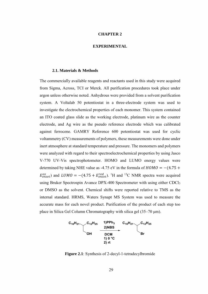
29
CHAPTER 2
EXPERIMENTAL
2.1. Materials & Methods
The commercially available reagents and reactants used in this study were acquired
from Sigma, Across, TCI or Merck. All purification procedures took place under
argon unless otherwise noted. Anhydrous were provided from a solvent purification
system. A Voltalab 50 potentiostat in a three-electrode system was used to
investigate the electrochemical properties of each monomer. This system contained
an ITO coated glass slide as the working electrode, platinum wire as the counter
electrode, and Ag wire as the pseudo reference electrode which was calibrated
against ferrocene. GAMRY Reference 600 potentiostat was used for cyclic
voltammetry (CV) measurements of polymers, these measurements were done under
inert atmosphere at standard temperature and pressure. The monomers and polymers
were analyzed with regard to their spectroelectrochemical properties by using Jasco
V-770 UV-Vis spectrophotometer. HOMO and LUMO energy values were
determined by taking NHE value as -4.75 eV in the formula of 𝐻𝑂𝑀𝑂 = −(4.75 +
𝐸𝑜𝑛𝑠𝑒𝑡𝑜𝑥 ) and 𝐿𝑈𝑀𝑂 = −(4.75 + 𝐸𝑜𝑛𝑠𝑒𝑡
𝑟𝑒𝑑 ). 1H and 13C NMR spectra were acquired
using Bruker Spectrospin Avance DPX-400 Spectrometer with using either CDCl3
or DMSO as the solvent. Chemical shifts were reported relative to TMS as the
internal standard. HRMS, Waters Synapt MS System was used to measure the
accurate mass for each novel product. Purification of the product of each step too
place in Silica Gel Column Chromatography with silica gel (35–70 μm).
Figure 2.1: Synthesis of 2-decyl-1-tetradecylbromide
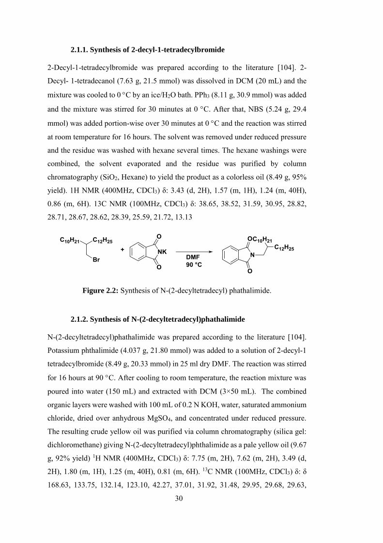
30
2.1.1. Synthesis of 2-decyl-1-tetradecylbromide
2-Decyl-1-tetradecylbromide was prepared according to the literature [104]. 2-
Decyl- 1-tetradecanol (7.63 g, 21.5 mmol) was dissolved in DCM (20 mL) and the
mixture was cooled to 0 C by an ice/H2O bath. PPh3 (8.11 g, 30.9 mmol) was added
and the mixture was stirred for 30 minutes at 0 C. After that, NBS (5.24 g, 29.4
mmol) was added portion-wise over 30 minutes at 0 C and the reaction was stirred
at room temperature for 16 hours. The solvent was removed under reduced pressure
and the residue was washed with hexane several times. The hexane washings were
combined, the solvent evaporated and the residue was purified by column
chromatography (SiO2, Hexane) to yield the product as a colorless oil (8.49 g, 95%
yield). 1H NMR (400MHz, CDCl3) δ: 3.43 (d, 2H), 1.57 (m, 1H), 1.24 (m, 40H),
0.86 (m, 6H). 13C NMR (100MHz, CDCl3) δ: 38.65, 38.52, 31.59, 30.95, 28.82,
28.71, 28.67, 28.62, 28.39, 25.59, 21.72, 13.13
Figure 2.2: Synthesis of N-(2-decyltetradecyl) phathalimide.
2.1.2. Synthesis of N-(2-decyltetradecyl)phathalimide
N-(2-decyltetradecyl)phathalimide was prepared according to the literature [104].
Potassium phthalimide (4.037 g, 21.80 mmol) was added to a solution of 2-decyl-1
tetradecylbromide (8.49 g, 20.33 mmol) in 25 ml dry DMF. The reaction was stirred
for 16 hours at 90 C. After cooling to room temperature, the reaction mixture was
poured into water (150 mL) and extracted with DCM (3×50 mL). The combined
organic layers were washed with 100 mL of 0.2 N KOH, water, saturated ammonium
chloride, dried over anhydrous MgSO4, and concentrated under reduced pressure.
The resulting crude yellow oil was purified via column chromatography (silica gel:
dichloromethane) giving N-(2-decyltetradecyl)phthalimide as a pale yellow oil (9.67
g, 92% yield) 1H NMR (400MHz, CDCl3) δ: 7.75 (m, 2H), 7.62 (m, 2H), 3.49 (d,
2H), 1.80 (m, 1H), 1.25 (m, 40H), 0.81 (m, 6H). 13C NMR (100MHz, CDCl3) δ: δ
168.63, 133.75, 132.14, 123.10, 42.27, 37.01, 31.92, 31.48, 29.95, 29.68, 29.63,
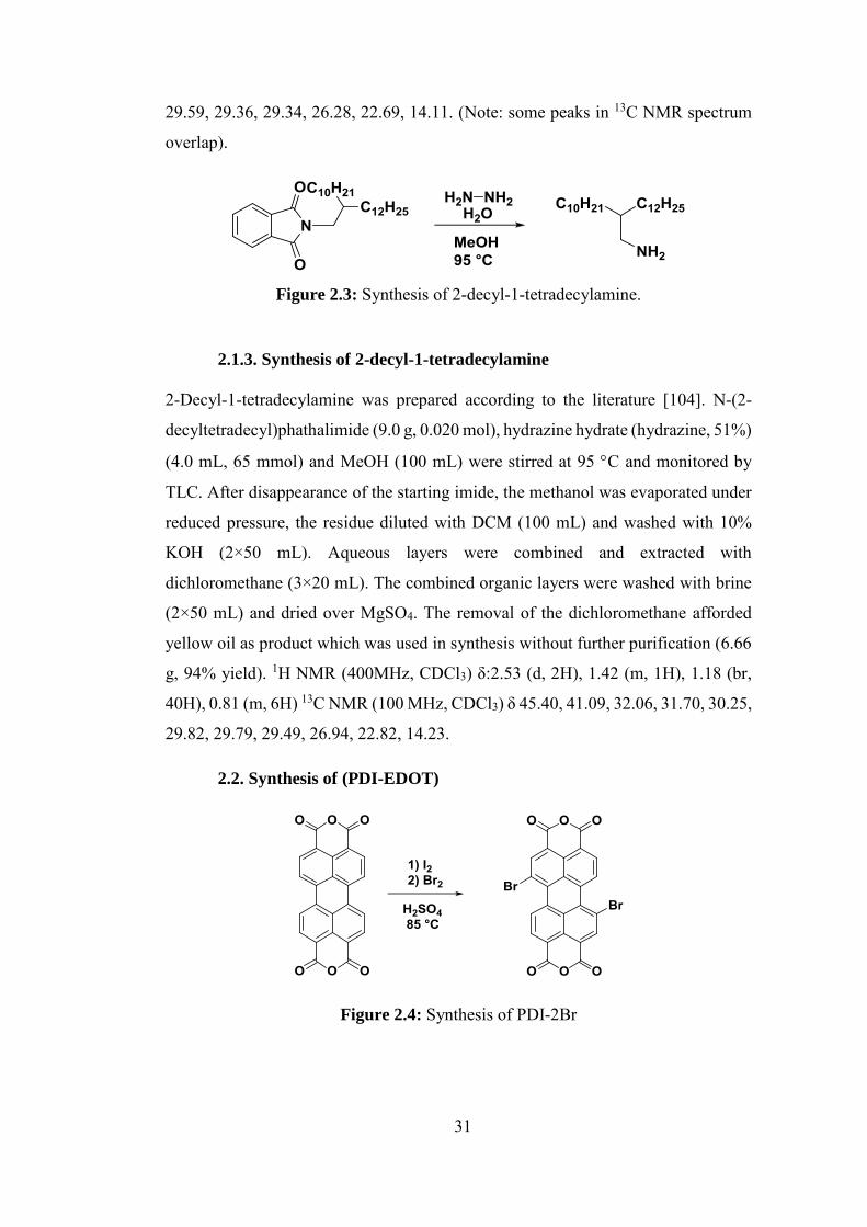
31
29.59, 29.36, 29.34, 26.28, 22.69, 14.11. (Note: some peaks in 13C NMR spectrum
overlap).
Figure 2.3: Synthesis of 2-decyl-1-tetradecylamine.
2.1.3. Synthesis of 2-decyl-1-tetradecylamine
2-Decyl-1-tetradecylamine was prepared according to the literature [104]. N-(2-
decyltetradecyl)phathalimide (9.0 g, 0.020 mol), hydrazine hydrate (hydrazine, 51%)
(4.0 mL, 65 mmol) and MeOH (100 mL) were stirred at 95 C and monitored by
TLC. After disappearance of the starting imide, the methanol was evaporated under
reduced pressure, the residue diluted with DCM (100 mL) and washed with 10%
KOH (2×50 mL). Aqueous layers were combined and extracted with
dichloromethane (3×20 mL). The combined organic layers were washed with brine
(2×50 mL) and dried over MgSO4. The removal of the dichloromethane afforded
yellow oil as product which was used in synthesis without further purification (6.66
g, 94% yield). 1H NMR (400MHz, CDCl3) δ:2.53 (d, 2H), 1.42 (m, 1H), 1.18 (br,
40H), 0.81 (m, 6H) 13C NMR (100 MHz, CDCl3) δ 45.40, 41.09, 32.06, 31.70, 30.25,
29.82, 29.79, 29.49, 26.94, 22.82, 14.23.
2.2. Synthesis of (PDI-EDOT)
Figure 2.4: Synthesis of PDI-2Br
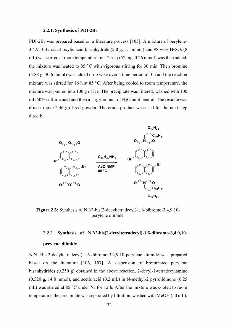
32
2.2.1. Synthesis of PDI-2Br
PDI-2Br was prepared based on a literature process [105]. A mixture of perylene-
3,4:9,10-tetracarboxylic acid bisanhydride (2.0 g, 5.1 mmol) and 98 wt% H2SO4 (8
mL) was stirred at room temperature for 12 h. I2 (52 mg, 0.26 mmol) was then added,
the mixture was heated to 85 C with vigorous stirring for 30 min. Then bromine
(4.88 g, 30.6 mmol) was added drop wise over a time period of 3 h and the reaction
mixture was stirred for 16 h at 85 C. After being cooled to room temperature, the
mixture was poured into 100 g of ice. The precipitate was filtered, washed with 100
mL 50% sulfuric acid and then a large amount of H2O until neutral. The residue was
dried to give 2.46 g of red powder. The crude product was used for the next step
directly.
Figure 2.5: Synthesis of N,N’-bis(2-decyltetradecyl)-1,6-bibromo-3,4,9,10-perylene diimide.
2.2.2. Synthesis of N,N’-bis(2-decyltetradecyl)-1,6-dibromo-3,4,9,10-
perylene diimide
N,N’-Bis(2-decyltetradecyl)-1,6-dibromo-3,4,9,10-perylene diimide was prepared
based on the literature [106, 107]. A suspension of brominated perylene
bisanhydrides (0.250 g) obtained in the above reaction, 2-decyl-1-tetradecylamine
(0.520 g, 14.8 mmol), and acetic acid (0.2 mL) in N-methyl-2 pyrrolidinone (6.25
mL) was stirred at 85 °C under N2 for 12 h. After the mixture was cooled to room
temperature, the precipitate was separated by filtration, washed with MeOH (50 mL),
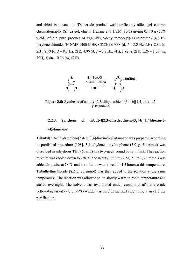
33
and dried in a vacuum. The crude product was purified by silica gel column
chromatography (Silica gel, eluent, Hexane and DCM, 10:3) giving 0.110 g (20%
yield) of the pure product of N,N’-bis(2-decyltetradecyl)-1,6-dibromo-3,4,9,10-
perylene diimide. 1H NMR (400 MHz, CDCl3) δ 9.38 (d, J = 8.2 Hz, 2H), 8.82 (s,
2H), 8.59 (d, J = 8.2 Hz, 2H), 4.06 (d, J = 7.2 Hz, 4H), 1.92 (s, 2H), 1.26 – 1.07 (m,
80H), 0.80 – 0.76 (m, 12H).
Figure 2.6: Synthesis of tributyl(2,3-dihydrothieno[3,4-b][1,4]dioxin-5-yl)stannane.
2.2.3. Synthesis of tributyl(2,3-dihydrothieno[3,4-b][1,4]dioxin-5-
yl)stannane
Tributyl(2,3-dihydrothieno[3,4-b][1,4]dioxin-5-yl)stannane was prepared according
to published procedure [108]. 3,4-ethylenedioxythiophene (3.0 g, 21 mmol) was
dissolved in anhydrous THF (60 mL) in a two-neck round bottom flask. The reaction
mixture was cooled down to -78 °C and n-butyllithium (2 M, 9.3 mL, 23 mmol) was
added dropwise at 78 °C and the solution was stirred for 1.5 hours at this temperature.
Tributhyltinchloride (8.2 g, 25 mmol) was then added to the solution at the same
temperature. The reaction was allowed to to slowly warm to room temperature and
stirred overnight. The solvent was evaporated under vacuum to afford a crude
yellow-brown oil (9.0 g, 99%) which was used in the next step without any further
purification.
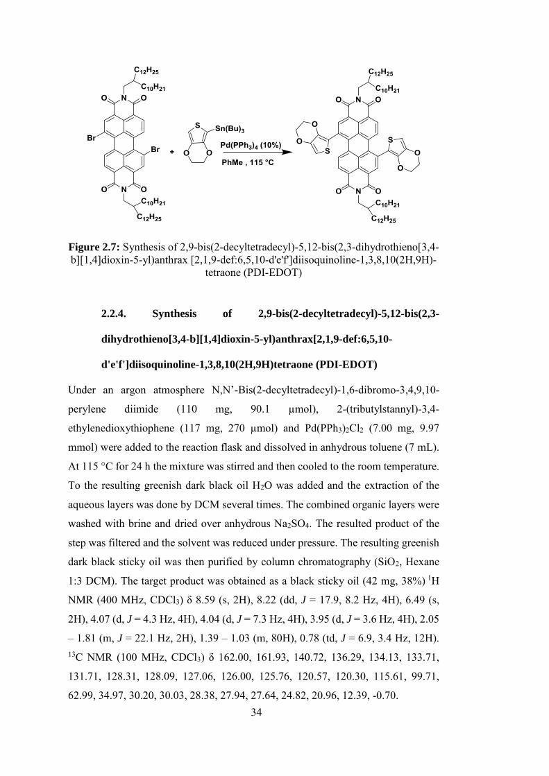
34
Figure 2.7: Synthesis of 2,9-bis(2-decyltetradecyl)-5,12-bis(2,3-dihydrothieno[3,4-b][1,4]dioxin-5-yl)anthrax [2,1,9-def:6,5,10-d'e'f']diisoquinoline-1,3,8,10(2H,9H)-
tetraone (PDI-EDOT)
2.2.4. Synthesis of 2,9-bis(2-decyltetradecyl)-5,12-bis(2,3-
dihydrothieno[3,4-b][1,4]dioxin-5-yl)anthrax[2,1,9-def:6,5,10-
d'e'f']diisoquinoline-1,3,8,10(2H,9H)tetraone (PDI-EDOT)
Under an argon atmosphere N,N’-Bis(2-decyltetradecyl)-1,6-dibromo-3,4,9,10-
perylene diimide (110 mg, 90.1 µmol), 2-(tributylstannyl)-3,4-
ethylenedioxythiophene (117 mg, 270 µmol) and Pd(PPh3)2Cl2 (7.00 mg, 9.97
mmol) were added to the reaction flask and dissolved in anhydrous toluene (7 mL).
At 115 °C for 24 h the mixture was stirred and then cooled to the room temperature.
To the resulting greenish dark black oil H2O was added and the extraction of the
aqueous layers was done by DCM several times. The combined organic layers were
washed with brine and dried over anhydrous Na2SO4. The resulted product of the
step was filtered and the solvent was reduced under pressure. The resulting greenish
dark black sticky oil was then purified by column chromatography (SiO2, Hexane
1:3 DCM). The target product was obtained as a black sticky oil (42 mg, 38%) 1H
NMR (400 MHz, CDCl3) δ 8.59 (s, 2H), 8.22 (dd, J = 17.9, 8.2 Hz, 4H), 6.49 (s,
2H), 4.07 (d, J = 4.3 Hz, 4H), 4.04 (d, J = 7.3 Hz, 4H), 3.95 (d, J = 3.6 Hz, 4H), 2.05
– 1.81 (m, J = 22.1 Hz, 2H), 1.39 – 1.03 (m, 80H), 0.78 (td, J = 6.9, 3.4 Hz, 12H). 13C NMR (100 MHz, CDCl3) δ 162.00, 161.93, 140.72, 136.29, 134.13, 133.71,
131.71, 128.31, 128.09, 127.06, 126.00, 125.76, 120.57, 120.30, 115.61, 99.71,
62.99, 34.97, 30.20, 30.03, 28.38, 27.94, 27.64, 24.82, 20.96, 12.39, -0.70.
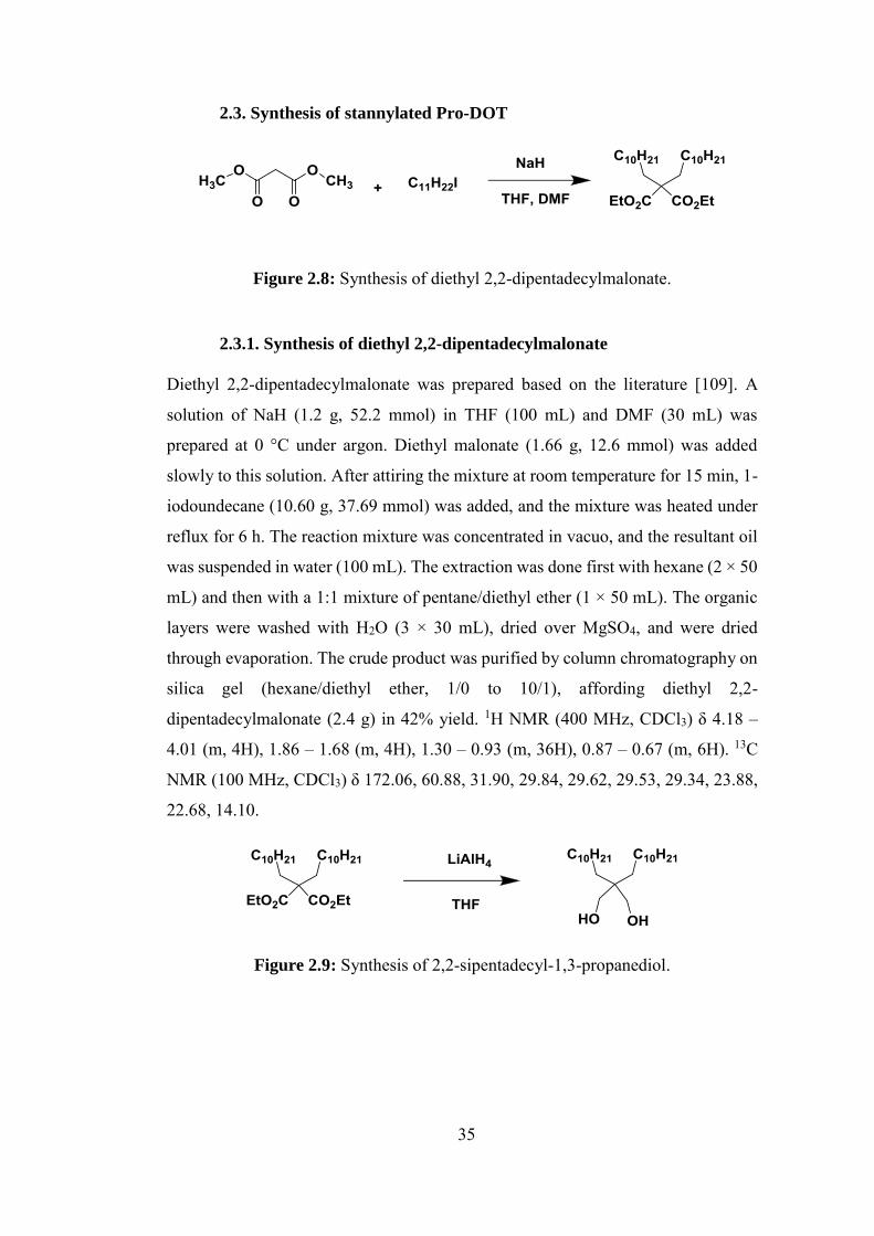
35
2.3. Synthesis of stannylated Pro-DOT
Figure 2.8: Synthesis of diethyl 2,2-dipentadecylmalonate.
2.3.1. Synthesis of diethyl 2,2-dipentadecylmalonate
Diethyl 2,2-dipentadecylmalonate was prepared based on the literature [109]. A
solution of NaH (1.2 g, 52.2 mmol) in THF (100 mL) and DMF (30 mL) was
prepared at 0 °C under argon. Diethyl malonate (1.66 g, 12.6 mmol) was added
slowly to this solution. After attiring the mixture at room temperature for 15 min, 1-
iodoundecane (10.60 g, 37.69 mmol) was added, and the mixture was heated under
reflux for 6 h. The reaction mixture was concentrated in vacuo, and the resultant oil
was suspended in water (100 mL). The extraction was done first with hexane (2 × 50
mL) and then with a 1:1 mixture of pentane/diethyl ether (1 × 50 mL). The organic
layers were washed with H2O (3 × 30 mL), dried over MgSO4, and were dried
through evaporation. The crude product was purified by column chromatography on
silica gel (hexane/diethyl ether, 1/0 to 10/1), affording diethyl 2,2-
dipentadecylmalonate (2.4 g) in 42% yield. 1H NMR (400 MHz, CDCl3) δ 4.18 –
4.01 (m, 4H), 1.86 – 1.68 (m, 4H), 1.30 – 0.93 (m, 36H), 0.87 – 0.67 (m, 6H). 13C
NMR (100 MHz, CDCl3) δ 172.06, 60.88, 31.90, 29.84, 29.62, 29.53, 29.34, 23.88,
22.68, 14.10.
Figure 2.9: Synthesis of 2,2-sipentadecyl-1,3-propanediol.
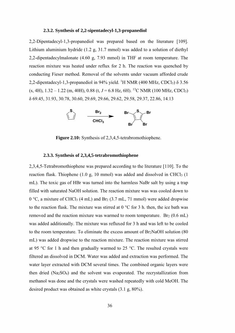
36
2.3.2. Synthesis of 2,2-sipentadecyl-1,3-propanediol
2,2-Dipentadecyl-1,3-propanediol was prepared based on the literature [109].
Lithium aluminium hydride (1.2 g, 31.7 mmol) was added to a solution of diethyl
2,2-dipentadecylmalonate (4.60 g, 7.93 mmol) in THF at room temperature. The
reaction mixture was heated under reflux for 2 h. The reaction was quenched by
conducting Fieser method. Removal of the solvents under vacuum afforded crude
2,2-dipentadecyl-1,3-propanediol in 94% yield. 1H NMR (400 MHz, CDCl3) δ 3.56
(s, 4H), 1.32 – 1.22 (m, 40H), 0.88 (t, J = 6.8 Hz, 6H). 13C NMR (100 MHz, CDCl3)
δ 69.45, 31.93, 30.78, 30.60, 29.69, 29.66, 29.62, 29.58, 29.37, 22.86, 14.13
Figure 2.10: Synthesis of 2,3,4,5-tetrabromothiophene.
2.3.3. Synthesis of 2,3,4,5-tetrabromothiophene
2,3,4,5-Tetrabromothiophene was prepared according to the literature [110]. To the
reaction flask. Thiophene (1.0 g, 10 mmol) was added and dissolved in CHCl3 (1
mL). The toxic gas of HBr was turned into the harmless NaBr salt by using a trap
filled with saturated NaOH solution. The reaction mixture was was cooled down to
0 °C, a mixture of CHCl3 (4 mL) and Br2 (3.7 mL, 71 mmol) were added dropwise
to the reaction flask. The mixture was stirred at 0 °C for 3 h. then, the ice bath was
removed and the reaction mixture was warmed to room temperature. Br2 (0.6 mL)
was added additionally. The mixture was refluxed for 3 h and was left to be cooled
to the room temperature. To eliminate the excess amount of Br2NaOH solution (80
mL) was added dropwise to the reaction mixture. The reaction mixture was stirred
at 95 °C for 1 h and then gradually warmed to 25 °C. The resulted crystals were
filtered an dissolved in DCM. Water was added and extraction was performed. The
water layer extracted with DCM several times. The combined organic layers were
then dried (Na2SO4) and the solvent was evaporated. The recrystallization from
methanol was done and the crystals were washed repeatedly with cold MeOH. The
desired product was obtained as white crystals (3.1 g, 80%).”
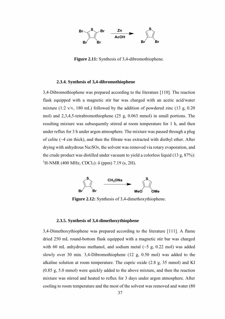
37
Figure 2.11: Synthesis of 3,4-dibromothiophene.
2.3.4. Synthesis of 3,4-dibromothiophene
3,4-Dibromothiophene was prepared according to the literature [110]. The reaction
flask equipped with a magnetic stir bar was charged with an acetic acid/water
mixture (1:2 v/v, 180 mL) followed by the addition of powdered zinc (13 g, 0.20
mol) and 2,3,4,5-tetrabromothiophene (25 g, 0.063 mmol) in small portions. The
resulting mixture was subsequently stirred at room temperature for 1 h, and then
under reflux for 3 h under argon atmosphere. The mixture was passed through a plug
of celite (~4 cm thick), and then the filtrate was extracted with diethyl ether. After
drying with anhydrous Na2SO4, the solvent was removed via rotary evaporation, and
the crude product was distilled under vacuum to yield a colorless liquid (13 g, 87%): 1H-NMR (400 MHz, CDCl3): δ (ppm) 7.19 (s, 2H).
Figure 2.12: Synthesis of 3,4-dimethoxythiophene.
2.3.5. Synthesis of 3,4-dimethoxythiophene
3,4-Dimethoxythiophene was prepared according to the literature [111]. A flame
dried 250 mL round-bottom flask equipped with a magnetic stir bar was charged
with 60 mL anhydrous methanol, and sodium metal (~5 g, 0.22 mol) was added
slowly over 30 min. 3,4-Dibromothiophene (12 g, 0.50 mol) was added to the
alkaline solution at room temperature. The cupric oxide (2.8 g, 35 mmol) and KI
(0.85 g, 5.0 mmol) were quickly added to the above mixture, and then the reaction
mixture was stirred and heated to reflux for 3 days under argon atmosphere. After
cooling to room temperature and the most of the solvent was removed and water (80
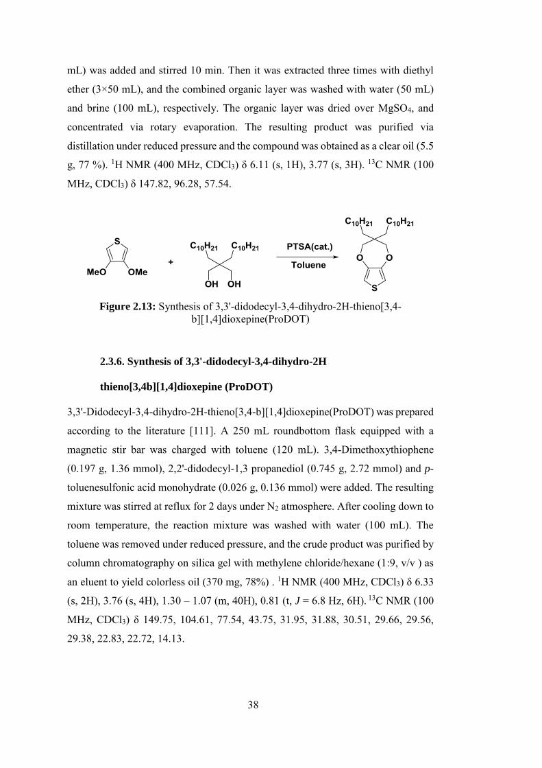
38
mL) was added and stirred 10 min. Then it was extracted three times with diethyl
ether (3×50 mL), and the combined organic layer was washed with water (50 mL)
and brine (100 mL), respectively. The organic layer was dried over MgSO4, and
concentrated via rotary evaporation. The resulting product was purified via
distillation under reduced pressure and the compound was obtained as a clear oil (5.5
g, 77 %). 1H NMR (400 MHz, CDCl3) δ 6.11 (s, 1H), 3.77 (s, 3H). 13C NMR (100
MHz, CDCl3) δ 147.82, 96.28, 57.54.
Figure 2.13: Synthesis of 3,3'-didodecyl-3,4-dihydro-2H-thieno[3,4-
b][1,4]dioxepine(ProDOT)
2.3.6. Synthesis of 3,3'-didodecyl-3,4-dihydro-2H
thieno[3,4b][1,4]dioxepine (ProDOT)
3,3'-Didodecyl-3,4-dihydro-2H-thieno[3,4-b][1,4]dioxepine(ProDOT) was prepared
according to the literature [111]. A 250 mL roundbottom flask equipped with a
magnetic stir bar was charged with toluene (120 mL). 3,4-Dimethoxythiophene
(0.197 g, 1.36 mmol), 2,2'-didodecyl-1,3 propanediol (0.745 g, 2.72 mmol) and p-
toluenesulfonic acid monohydrate (0.026 g, 0.136 mmol) were added. The resulting
mixture was stirred at reflux for 2 days under N2 atmosphere. After cooling down to
room temperature, the reaction mixture was washed with water (100 mL). The
toluene was removed under reduced pressure, and the crude product was purified by
column chromatography on silica gel with methylene chloride/hexane (1:9, v/v ) as
an eluent to yield colorless oil (370 mg, 78%) . 1H NMR (400 MHz, CDCl3) δ 6.33
(s, 2H), 3.76 (s, 4H), 1.30 – 1.07 (m, 40H), 0.81 (t, J = 6.8 Hz, 6H). 13C NMR (100
MHz, CDCl3) δ 149.75, 104.61, 77.54, 43.75, 31.95, 31.88, 30.51, 29.66, 29.56,
29.38, 22.83, 22.72, 14.13.
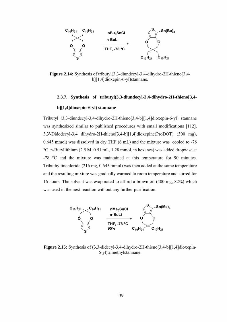
39
Figure 2.14: Synthesis of tributyl(3,3-diundecyl-3,4-dihydro-2H-thieno[3,4-b][1,4]dioxepin-6-yl)stannane.
2.3.7. Synthesis of tributyl(3,3-diundecyl-3,4-dihydro-2H-thieno[3,4-
b][1,4]dioxepin-6-yl) stannane
Tributyl (3,3-diundecyl-3,4-dihydro-2H-thieno[3,4-b][1,4]dioxepin-6-yl) stannane
was synthesized similar to published procedures with small modifications [112].
3,3'-Didodecyl-3,4 dihydro-2H-thieno[3,4-b][1,4]dioxepine(ProDOT) (300 mg),
0.645 mmol) was dissolved in dry THF (6 mL) and the mixture was cooled to -78
°C. n-Butyllithium (2.5 M, 0.51 mL, 1.28 mmol, in hexanes) was added dropwise at
-78 °C and the mixture was maintained at this temperature for 90 minutes.
Tributhyltinchloride (216 mg, 0.645 mmol) was then added at the same temperature
and the resulting mixture was gradually warmed to room temperature and stirred for
16 hours. The solvent was evaporated to afford a brown oil (400 mg, 82%) which
was used in the next reaction without any further purification.
Figure 2.15: Synthesis of (3,3-didecyl-3,4-dihydro-2H-thieno[3,4-b][1,4]dioxepin-6-yl)trimethylstannane.
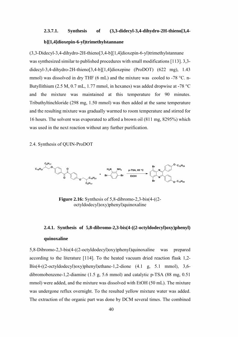
40
2.3.7.1. Synthesis of (3,3-didecyl-3,4-dihydro-2H-thieno[3,4-
b][1,4]dioxepin-6-yl)trimethylstannane
(3,3-Didecyl-3,4-dihydro-2H-thieno[3,4-b][1,4]dioxepin-6-yl)trimethylstannane
was synthesized similar to published procedures with small modifications [113]. 3,3-
didecyl-3,4-dihydro-2H-thieno[3,4-b][1,4]dioxepine (ProDOT) (622 mg), 1.43
mmol) was dissolved in dry THF (6 mL) and the mixture was cooled to -78 °C. n-
Butyllithium (2.5 M, 0.7 mL, 1.77 mmol, in hexanes) was added dropwise at -78 °C
and the mixture was maintained at this temperature for 90 minutes.
Tributhyltinchloride (298 mg, 1.50 mmol) was then added at the same temperature
and the resulting mixture was gradually warmed to room temperature and stirred for
16 hours. The solvent was evaporated to afford a brown oil (811 mg, 8295%) which
was used in the next reaction without any further purification.
2.4. Synthesis of QUIN-ProDOT
Figure 2.16: Synthesis of 5,8-dibromo-2,3-bis(4-((2-octyldodecyl)oxy)phenyl)quinoxaline
2.4.1. Synthesis of 5,8-dibromo-2,3-bis(4-((2-octyldodecyl)oxy)phenyl)
quinoxaline
5,8-Dibromo-2,3-bis(4-((2-octyldodecyl)oxy)phenyl)quinoxaline was prepared
according to the literature [114]. To the heated vacuum dried reaction flask 1,2-
Bis(4-((2-octyldodecyl)oxy)phenyl)ethane-1,2-dione (4.1 g, 5.1 mmol), 3,6-
dibromobenzene-1,2-diamine (1.5 g, 5.6 mmol) and catalytic p-TSA (88 mg, 0.51
mmol) were added, and the mixture was dissolved with EtOH (50 mL). The mixture
was undergone reflux overnight. To the resulted yellow mixture water was added.
The extraction of the organic part was done by DCM several times. The combined
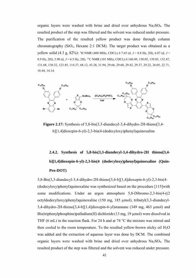
41
organic layers were washed with brine and dried over anhydrous Na2SO4. The
resulted product of the step was filtered and the solvent was reduced under pressure.
The purification of the resulted yellow product was done through column
chromatography (SiO2, Hexane 2:1 DCM). The target product was obtained as a
yellow solid (4.3 g, 82%): 1H NMR (400 MHz, CDCl3) δ 7.65 (d, J = 8.8 Hz, 2H), 6.87 (d, J =
8.9 Hz, 2H), 3.98 (d, J = 6.5 Hz, 2H). 13C NMR (101 MHz, CDCl3) δ 160.49, 158.05, 139.03, 132.47,
131.68, 130.32, 123.45, 114.37, 68.12, 43.28, 31.94, 29.66, 29.60, 29.42, 29.37, 29.22, 26.05, 22.71,
18.44, 14.14.
Figure 2.17: Synthesis of 5,8-bis(3,3-diundecyl-3,4-dihydro-2H-thieno[3,4-
b][1,4]dioxepin-6-yl)-2,3-bis(4-(dodecyloxy)phenyl)quinoxaline
2.4.2. Synthesis of 5,8-bis(3,3-diundecyl-3,4-dihydro-2H thieno[3,4-
b][1,4]dioxepin-6-yl)-2,3-bis(4 (dodecyloxy)phenyl)quinoxaline (Quin-
Pro-DOT)
5,8-Bis(3,3-diundecyl-3,4-dihydro-2H-thieno[3,4-b][1,4]dioxepin-6-yl)-2,3-bis(4-
(dodecyloxy)phenyl)quinoxaline was synthesized based on the procedure [115]with
some modifications. Under an argon atmosphere 5,8-Dibromo-2,3-bis(4-((2
octyldodecyl)oxy)phenyl)quinoxaline (150 mg, 185 µmol), tributyl(3,3-diundecyl-
3,4-dihydro-2H-thieno[3,4-b][1,4]dioxepin-6-yl)stannane (349 mg, 463 µmol) and
Bis(triphenylphosphine)palladium(II) dichloride (13 mg, 19 µmol) were dissolved in
THF (6 mL) in the reaction flask. For 24 h and at 74 °C the mixture was stirred and
then cooled to the room temperature. To the resulted yellow-brown sticky oil H2O
was added and the extraction of aqueous layer was done by DCM. The combined
organic layers were washed with brine and dried over anhydrous Na2SO4. The
resulted product of the step was filtered and the solvent was reduced under pressure.
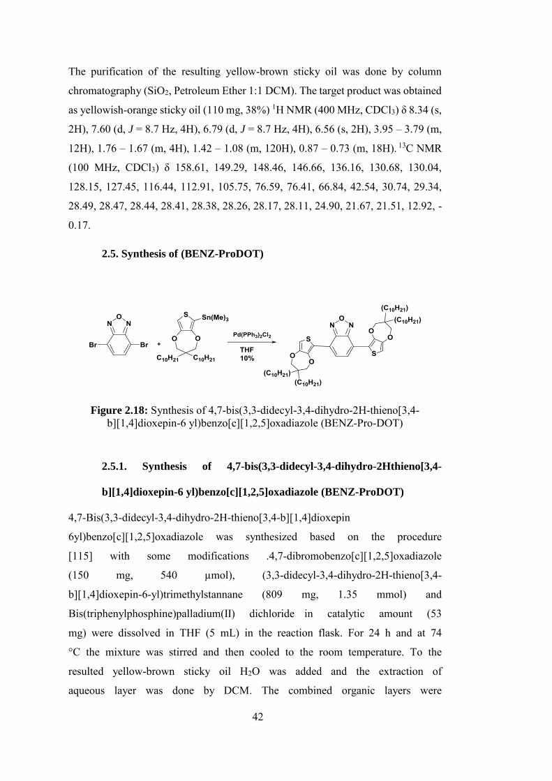
42
The purification of the resulting yellow-brown sticky oil was done by column
chromatography (SiO2, Petroleum Ether 1:1 DCM). The target product was obtained
as yellowish-orange sticky oil (110 mg, 38%) 1H NMR (400 MHz, CDCl3) δ 8.34 (s,
2H), 7.60 (d, J = 8.7 Hz, 4H), 6.79 (d, J = 8.7 Hz, 4H), 6.56 (s, 2H), 3.95 – 3.79 (m,
12H), 1.76 – 1.67 (m, 4H), 1.42 – 1.08 (m, 120H), 0.87 – 0.73 (m, 18H). 13C NMR
(100 MHz, CDCl3) δ 158.61, 149.29, 148.46, 146.66, 136.16, 130.68, 130.04,
128.15, 127.45, 116.44, 112.91, 105.75, 76.59, 76.41, 66.84, 42.54, 30.74, 29.34,
28.49, 28.47, 28.44, 28.41, 28.38, 28.26, 28.17, 28.11, 24.90, 21.67, 21.51, 12.92, -
0.17.
2.5. Synthesis of (BENZ-ProDOT)
Figure 2.18: Synthesis of 4,7-bis(3,3-didecyl-3,4-dihydro-2H-thieno[3,4-b][1,4]dioxepin-6 yl)benzo[c][1,2,5]oxadiazole (BENZ-Pro-DOT)
2.5.1. Synthesis of 4,7-bis(3,3-didecyl-3,4-dihydro-2Hthieno[3,4-
b][1,4]dioxepin-6 yl)benzo[c][1,2,5]oxadiazole (BENZ-ProDOT)
4,7-Bis(3,3-didecyl-3,4-dihydro-2H-thieno[3,4-b][1,4]dioxepin
6yl)benzo[c][1,2,5]oxadiazole was synthesized based on the procedure
[115] with some modifications .4,7-dibromobenzo[c][1,2,5]oxadiazole
(150 mg, 540 µmol), (3,3-didecyl-3,4-dihydro-2H-thieno[3,4-
b][1,4]dioxepin-6-yl)trimethylstannane (809 mg, 1.35 mmol) and
Bis(triphenylphosphine)palladium(II) dichloride in catalytic amount (53
mg) were dissolved in THF (5 mL) in the reaction flask. For 24 h and at 74
°C the mixture was stirred and then cooled to the room temperature. To the
resulted yellow-brown sticky oil H2O was added and the extraction of
aqueous layer was done by DCM. The combined organic layers were
43
washed with brine and dried over anhydrous Na2SO4. The resulted product
of the step was filtered and the solvent was reduced under pressure. The
resulting dark-red sticky oil was then purified by column chromatography
resulted in 53 mg of pure product (yield 10%). (SiO2, petroleum ether 1:1
DCM). 1H NMR (400 MHz, CDCl3) δ 7.99 (s, 2H), 6.57 (s, 2H), 3.99 (s,
4H), 3.88 (s, 4H), 1.59 – 0.93 (m, 64H), 0.81 (t, J = 6.8 Hz, 12H).

44
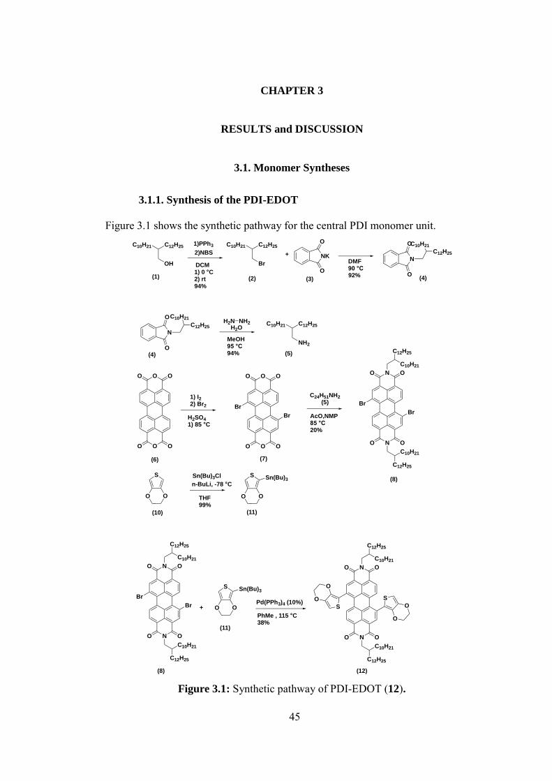
45
CHAPTER 3
RESULTS and DISCUSSION
3.1. Monomer Syntheses
3.1.1. Synthesis of the PDI-EDOT
Figure 3.1 shows the synthetic pathway for the central PDI monomer unit.
Figure 3.1: Synthetic pathway of PDI-EDOT (12).
C12H25
OH
C10H211)PPh3
2)NBS
DCM
C12H25
Br
C10H21
NK
O
O
DMF90 °C
N
O
O
+
MeOH95 °C94%
H2N NH2H2O
C12H25
NH2
C10H21
O
O
OO
O O
1) I2 2) Br2
H2SO4
1) 85 °C
O
O
OO
O O
Br
Br
N
N OO
O O
C12H25
C10H21
C10H21
C12H25
C24H51NH2
(5)
AcO,NMP85 °C20%
Br
Br
S
O O
S
O O
n-BuLi, -78 °C
N
N OO
O O
C12H25
C10H21
C10H21
C12H25
Br
Br
S
O O+
N
N OO
O O
C12H25
C10H21
C10H21
C12H25
S
S
O
O
O
O
PhMe , 115 °C38%
Pd(PPh3)4 (10%)
C10H21
C12H25
N
O
OC10H21
C12H25
Sn(Bu)3Sn(Bu)3Cl
Sn(Bu)3
1) 0 °C2) rt94%
92%
THF99%
(1) (2) (3) (4)
(4) (5)
(6) (7)
(8)
(10) (11)
(8)
(11)
(12)
46
The synthetic approach to PDI-ProDOT is shown in Figure 3.1. The synthesis started
with the commercially available alcohol 1. Bromination with NBS/PPh3 system gave
the bromo 2 in high yields. Towards the synthesis of the target amine 5 Gabriel
synthesis was applied. Thus, potassium phthalimide (3) was reacted with the bromo
2 and compound 4 was synthesized. Removal of the protecting group with
hydrazine/water gave the desired amine 5. Then perylene tetracarboxylic
dianhydride 6 was dibrominated in the presence of bromine/iodine and sulfuric acid
to give the dibromo compound 7. Condensation of anhydride 7 and amine 5 gave the
desired dibromo PDI 8. EDOT (10) was stannylated successfully and the resulting
compound 11 was coupled with PDI 8 under Stille coupling conditions to give target
compound 12.
3.1.2. Synthesis of the QUIN-ProDOT
Figure 3.2 shows the synthetic pathway for the QUIN-ProDOT monomer unit.
Commercially available diester 13 and alkyliodide 14 was reacted in the presence of
NaH to yield the doubly alkylated product 15. Diester 15 was reduced completely to
diol 16 in the presence of LiAlH4. Separately thiophene (17) was tetrabrominated in
the presence of bromine then the bromines at 2 and 5 positions were selectively
reduced to give 3,4-dibromothiophene (19). Etherification with NaOMe gave
compound 20. Transetherfication between 20 and diol 16 gave the dialkyl ProDOT
derivative 21. Stannylation was performed in the presence of n-BuLi and Sn(Bu)3Cl
to yield compound 22. Alkylated diketone 23 and diamine 24 which were in our
group inventory was condensed together to yield target dibromo quinoxaline 25.
Stille coupling between 25 and 22 gave the target donor-acceptor type monomer 26.
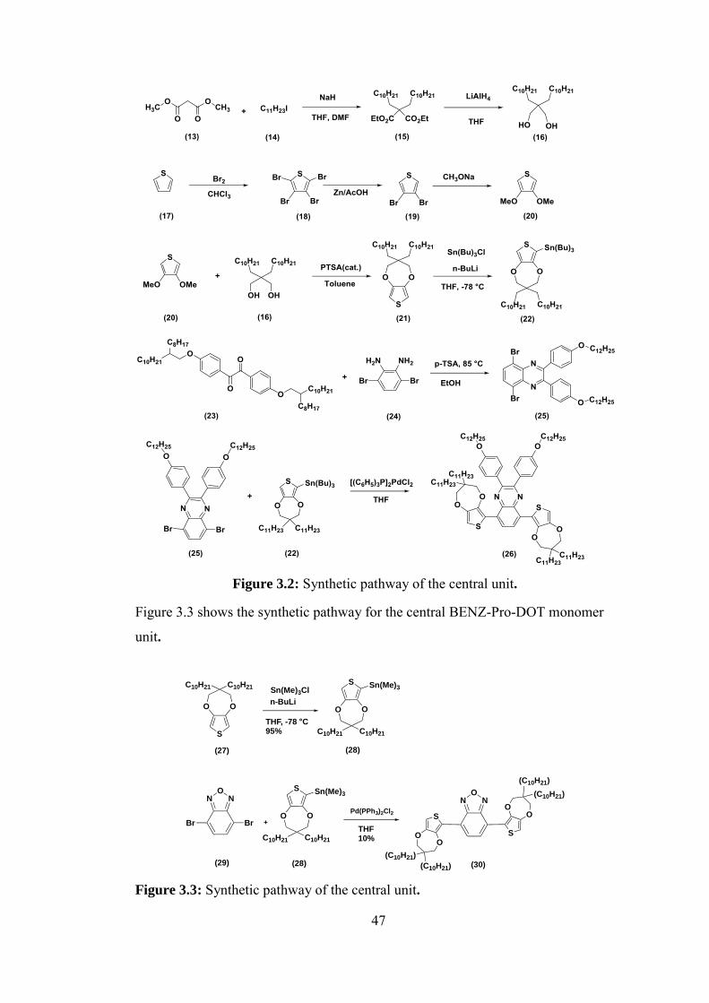
47
Figure 3.2: Synthetic pathway of the central unit.
Figure 3.3 shows the synthetic pathway for the central BENZ-Pro-DOT monomer
unit.
Figure 3.3: Synthetic pathway of the central unit.
S
OO
C10H21C10H21S
O O
C10H21 C10H21
N NO
Br Br
N NO
S
OO
(C10H21)
(C10H21)
S
OO
(C10H21)
(C10H21)
+
Sn(Me)3ClSn(Me)3
S
O O
C10H21 C10H21
Sn(Me)3
Pd(PPh3)2Cl2
THF10%
THF, -78 °C95%
n-BuLi
(27) (28)
(29) (28) (30)
48
A ProDOT derivative with different alkyl chain size that was in our group inventory
was successfully stannylated to yield compound 28. Coupling with commercially
available 4,7-dibromo-2,1,3-benzoxadiazole (29) gave the target donor-acceptor
type monomer 30.
3.2. Electrochemical and Electrochromic Properties of Polymers
3.2.1. Electropolymerization of Monomers
Electropolymerizations in this study were taken place under the following system;
the multiple scan voltammetry system was comprised of three electrodes where the
counter electrode was a platinum wire, an Ag wire was utilized as the reference
electrode and the ITO coated glass was introduced as the working electrode.
3.2.2. Spectroelectrochemistry Studies of Polymers
Optical changed of the conjugated polymers upon doping processes were
investigated via spectroelectrochemistry studies. These studies directly show the
evolution of charge carriers when polymer is progressively deoped. Polymer films
that are going to be used in this study were coated potentiodynamically on ITO . The
UV-vis-NIR spectra were recorded at different applied potentials in a monomer free
acetonitrile solution of 0.1 M TBAPF6.
3.2.3. Kinetic Studies of Polymers
In order to probe changes in transmittance with time, the kinetic studies for the
polymers were performed. To conduct such studies the polymer was repeatedly
stepped between the neutral and oxidized states. The response times and switching
abilities were investigated by performing the studies at the maximum absorption of
the polymers in their neutral state. The polymer film was deposited on ITO glass
slide by repeated scanning (15 cycles) in 0.1M TBAPF6/ACN (monomer free).
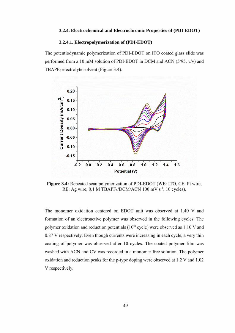
49
3.2.4. Electrochemical and Electrochromic Properties of (PDI-EDOT)
3.2.4.1. Electropolymerization of (PDI-EDOT)
The potentiodynamic polymerization of PDI-EDOT on ITO coated glass slide was
performed from a 10 mM solution of PDI-EDOT in DCM and ACN (5/95, v/v) and
TBAPF6 electrolyte solvent (Figure 3.4).
Figure 3.4: Repeated scan polymerization of PDI-EDOT (WE: ITO, CE: Pt wire,
RE: Ag wire, 0.1 M TBAPF6/DCM/ACN 100 mV s-1, 10 cycles).
The monomer oxidation centered on EDOT unit was observed at 1.40 V and
formation of an electroactive polymer was observed in the following cycles. The
polymer oxidation and reduction potentials (10th cycle) were observed as 1.10 V and
0.87 V respectively. Even though currents were increasing in each cycle, a very thin
coating of polymer was observed after 10 cycles. The coated polymer film was
washed with ACN and CV was recorded in a monomer free solution. The polymer
oxidation and reduction peaks for the p-type doping were observed at 1.2 V and 1.02
V respectively.
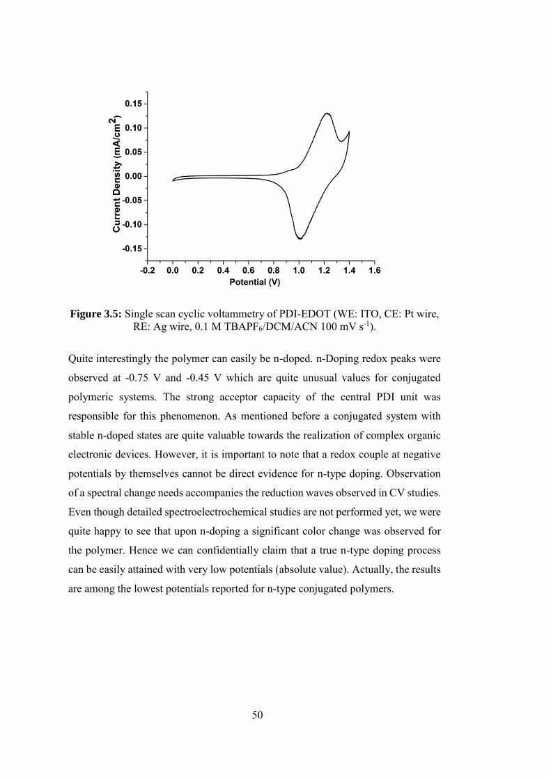
50
Figure 3.5: Single scan cyclic voltammetry of PDI-EDOT (WE: ITO, CE: Pt wire,
RE: Ag wire, 0.1 M TBAPF6/DCM/ACN 100 mV s-1).
Quite interestingly the polymer can easily be n-doped. n-Doping redox peaks were
observed at -0.75 V and -0.45 V which are quite unusual values for conjugated
polymeric systems. The strong acceptor capacity of the central PDI unit was
responsible for this phenomenon. As mentioned before a conjugated system with
stable n-doped states are quite valuable towards the realization of complex organic
electronic devices. However, it is important to note that a redox couple at negative
potentials by themselves cannot be direct evidence for n-type doping. Observation
of a spectral change needs accompanies the reduction waves observed in CV studies.
Even though detailed spectroelectrochemical studies are not performed yet, we were
quite happy to see that upon n-doping a significant color change was observed for
the polymer. Hence we can confidentially claim that a true n-type doping process
can be easily attained with very low potentials (absolute value). Actually, the results
are among the lowest potentials reported for n-type conjugated polymers.
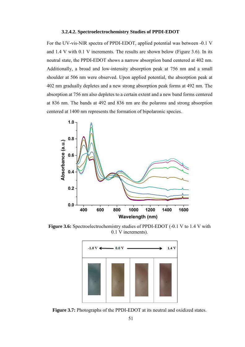
51
3.2.4.2. Spectroelectrochemistry Studies of PPDI-EDOT
For the UV-vis-NIR spectra of PPDI-EDOT, applied potential was between -0.1 V
and 1.4 V with 0.1 V increments. The results are shown below (Figure 3.6). In its
neutral state, the PPDI-EDOT shows a narrow absorption band centered at 402 nm.
Additionally, a broad and low-intensity absorption peak at 756 nm and a small
shoulder at 506 nm were observed. Upon applied potential, the absorption peak at
402 nm gradually depletes and a new strong absorption peak forms at 492 nm. The
absorption at 756 nm also depletes to a certain extent and a new band forms centered
at 836 nm. The bands at 492 and 836 nm are the polarons and strong absorption
centered at 1400 nm represents the formation of bipolaronic species.
Figure 3.6: Spectroelectrochemistry studies of PPDI-EDOT (-0.1 V to 1.4 V with
0.1 V increments).
Figure 3.7: Photographs of the PPDI-EDOT at its neutral and oxidized states.
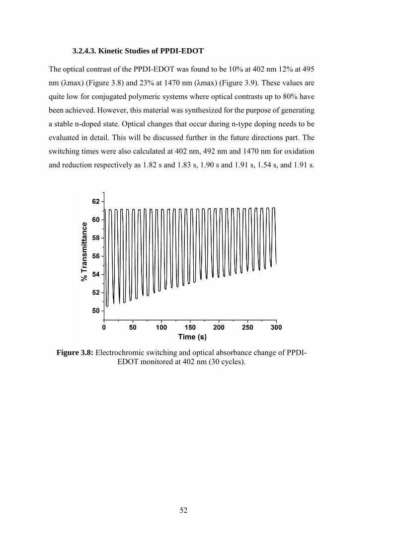
52
3.2.4.3. Kinetic Studies of PPDI-EDOT
The optical contrast of the PPDI-EDOT was found to be 10% at 402 nm 12% at 495
nm (λmax) (Figure 3.8) and 23% at 1470 nm (λmax) (Figure 3.9). These values are
quite low for conjugated polymeric systems where optical contrasts up to 80% have
been achieved. However, this material was synthesized for the purpose of generating
a stable n-doped state. Optical changes that occur during n-type doping needs to be
evaluated in detail. This will be discussed further in the future directions part. The
switching times were also calculated at 402 nm, 492 nm and 1470 nm for oxidation
and reduction respectively as 1.82 s and 1.83 s, 1.90 s and 1.91 s, 1.54 s, and 1.91 s.
Figure 3.8: Electrochromic switching and optical absorbance change of PPDI-
EDOT monitored at 402 nm (30 cycles).
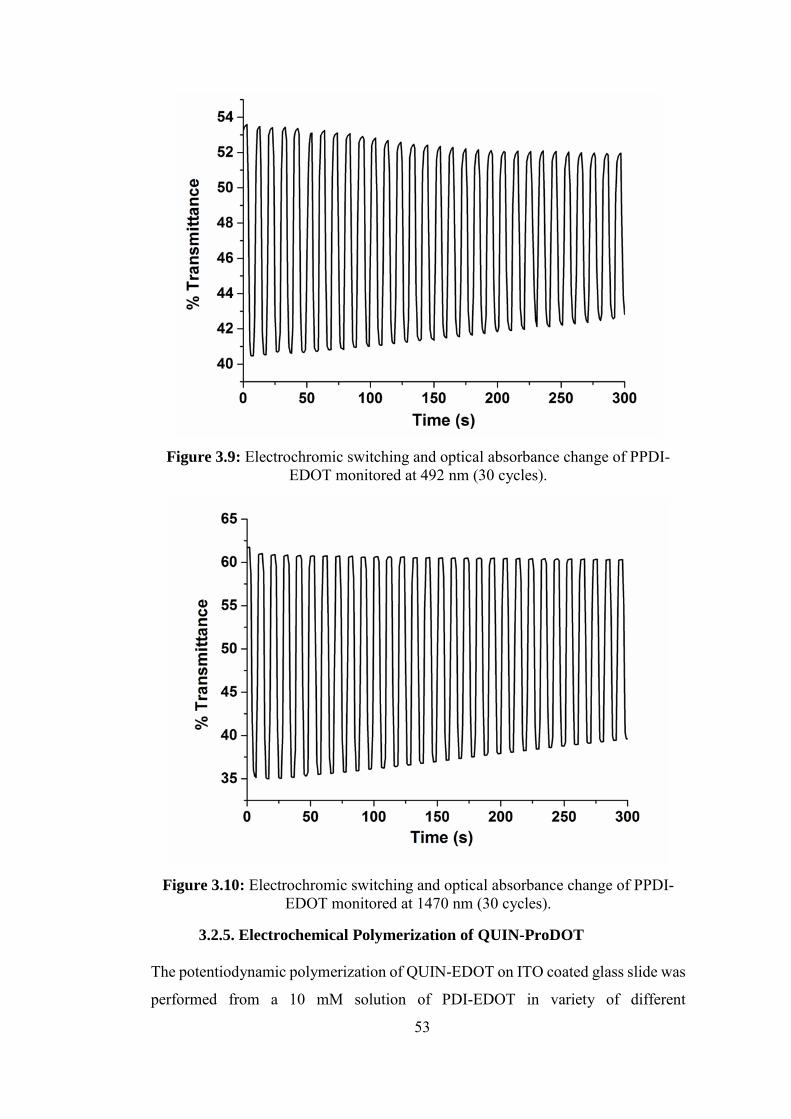
53
Figure 3.9: Electrochromic switching and optical absorbance change of PPDI-
EDOT monitored at 492 nm (30 cycles).
Figure 3.10: Electrochromic switching and optical absorbance change of PPDI-
EDOT monitored at 1470 nm (30 cycles).
3.2.5. Electrochemical Polymerization of QUIN-ProDOT
The potentiodynamic polymerization of QUIN-EDOT on ITO coated glass slide was
performed from a 10 mM solution of PDI-EDOT in variety of different
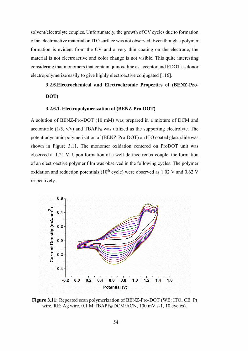
54
solvent/electrolyte couples. Unfortunately, the growth of CV cycles due to formation
of an electroactive material on ITO surface was not observed. Even though a polymer
formation is evident from the CV and a very thin coating on the electrode, the
material is not electroactive and color change is not visible. This quite interesting
considering that monomers that contain quinoxaline as acceptor and EDOT as donor
electropolymerize easily to give highly electroactive conjugated [116].
3.2.6.Electrochemical and Electrochromic Properties of (BENZ-Pro-
DOT)
3.2.6.1. Electropolymerization of (BENZ-Pro-DOT)
A solution of BENZ-Pro-DOT (10 mM) was prepared in a mixture of DCM and
acetonitrile (1/5, v/v) and TBAPF6 was utilized as the supporting electrolyte. The
potentiodynamic polymerization of (BENZ-Pro-DOT) on ITO coated glass slide was
shown in Figure 3.11. The monomer oxidation centered on ProDOT unit was
observed at 1.21 V. Upon formation of a well-defined redox couple, the formation
of an electroactive polymer film was observed in the following cycles. The polymer
oxidation and reduction potentials (10th cycle) were observed as 1.02 V and 0.62 V
respectively.
Figure 3.11: Repeated scan polymerization of BENZ-Pro-DOT (WE: ITO, CE: Pt
wire, RE: Ag wire, 0.1 M TBAPF6/DCM/ACN, 100 mV s-1, 10 cycles).
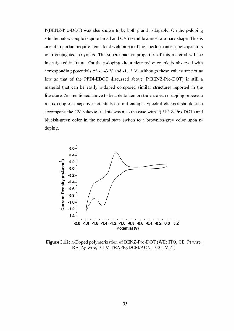
55
P(BENZ-Pro-DOT) was also shown to be both p and n-dopable. On the p-doping
site the redox couple is quite broad and CV resemble almost a square shape. This is
one of important requirements for development of high performance supercapacitors
with conjugated polymers. The supercapacitor properties of this material will be
investigated in future. On the n-doping site a clear redox couple is observed with
corresponding potentials of -1.43 V and -1.13 V. Although these values are not as
low as that of the PPDI-EDOT discussed above, P(BENZ-Pro-DOT) is still a
material that can be easily n-doped compared similar structures reported in the
literature. As mentioned above to be able to demonstrate a clean n-doping process a
redox couple at negative potentials are not enough. Spectral changes should also
accompany the CV behaviour. This was also the case with P(BENZ-Pro-DOT) and
blueish-green color in the neutral state switch to a brownish-grey color upon n-
doping.
Figure 3.12: n-Doped polymerization of BENZ-Pro-DOT (WE: ITO, CE: Pt wire,
RE: Ag wire, 0.1 M TBAPF6/DCM/ACN, 100 mV s-1)
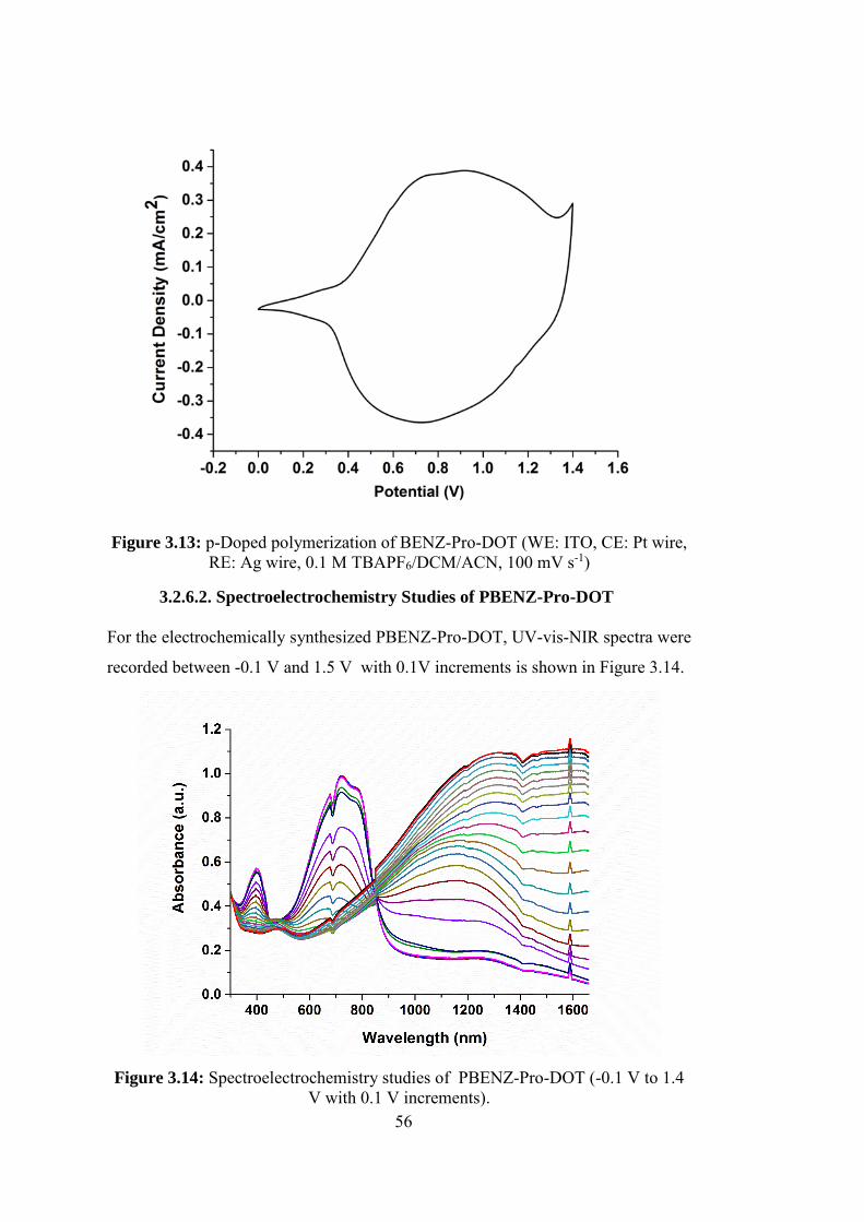
56
Figure 3.13: p-Doped polymerization of BENZ-Pro-DOT (WE: ITO, CE: Pt wire,
RE: Ag wire, 0.1 M TBAPF6/DCM/ACN, 100 mV s-1)
3.2.6.2. Spectroelectrochemistry Studies of PBENZ-Pro-DOT
For the electrochemically synthesized PBENZ-Pro-DOT, UV-vis-NIR spectra were
recorded between -0.1 V and 1.5 V with 0.1V increments is shown in Figure 3.14.
Figure 3.14: Spectroelectrochemistry studies of PBENZ-Pro-DOT (-0.1 V to 1.4
V with 0.1 V increments).
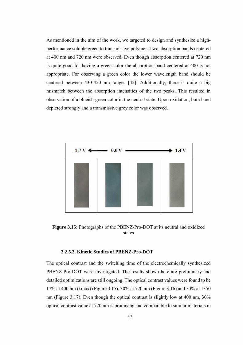
57
As mentioned in the aim of the work, we targeted to design and synthesize a high-
performance soluble green to transmissive polymer. Two absorption bands centered
at 400 nm and 720 nm were observed. Even though absorption centered at 720 nm
is quite good for having a green color the absorption band centered at 400 is not
appropriate. For observing a green color the lower wavelength band should be
centered between 430-450 nm ranges [42]. Additionally, there is quite a big
mismatch between the absorption intensities of the two peaks. This resulted in
observation of a blueish-green color in the neutral state. Upon oxidation, both band
depleted strongly and a transmissive grey color was observed.
Figure 3.15: Photographs of the PBENZ-Pro-DOT at its neutral and oxidized states
3.2.5.3. Kinetic Studies of PBENZ-Pro-DOT
The optical contrast and the switching time of the electrochemically synthesized
PBENZ-Pro-DOT were investigated. The results shown here are preliminary and
detailed optimizations are still ongoing. The optical contrast values were found to be
17% at 400 nm (λmax) (Figure 3.15), 30% at 720 nm (Figure 3.16) and 50% at 1350
nm (Figure 3.17). Even though the optical contrast is slightly low at 400 nm, 30%
optical contrast value at 720 nm is promising and comparable to similar materials in
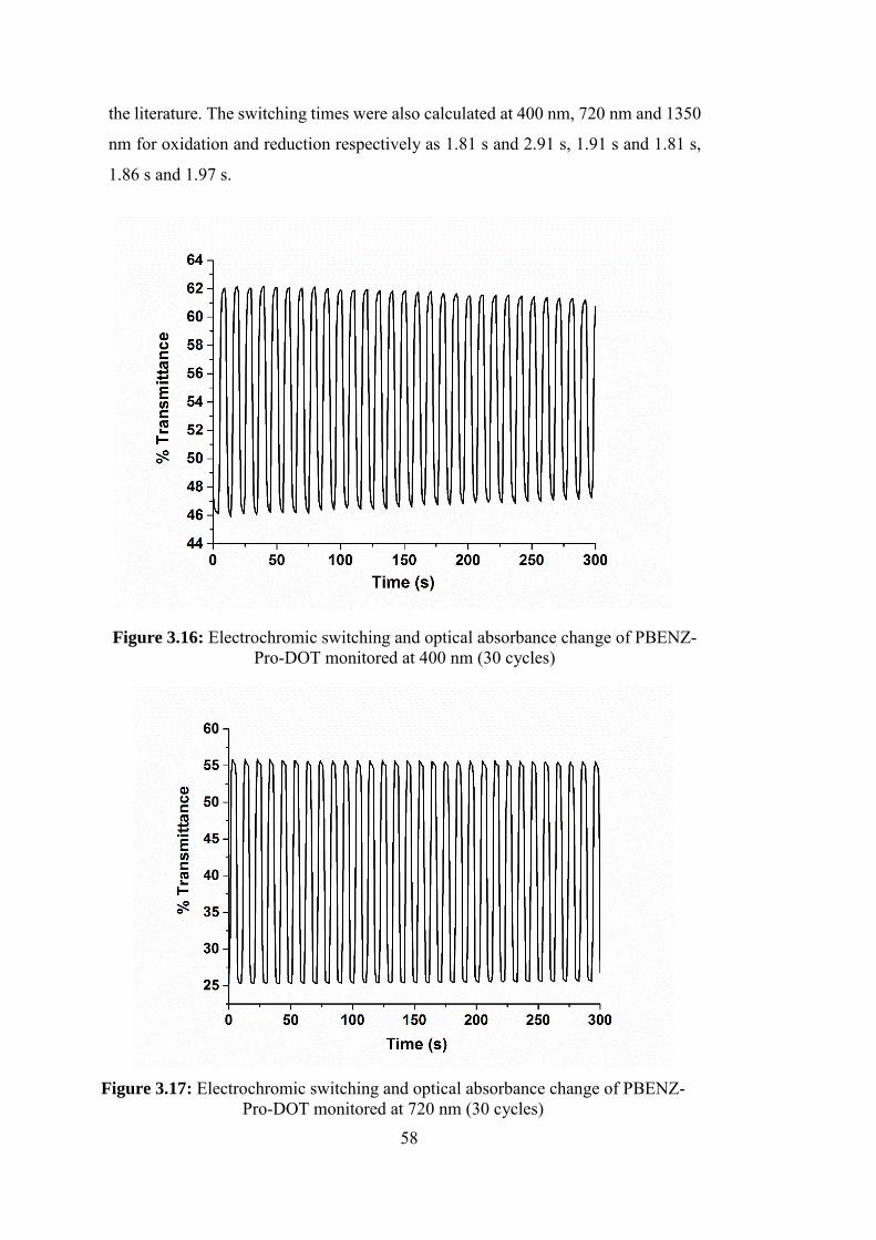
58
the literature. The switching times were also calculated at 400 nm, 720 nm and 1350
nm for oxidation and reduction respectively as 1.81 s and 2.91 s, 1.91 s and 1.81 s,
1.86 s and 1.97 s.
Figure 3.16: Electrochromic switching and optical absorbance change of PBENZ-
Pro-DOT monitored at 400 nm (30 cycles)
Figure 3.17: Electrochromic switching and optical absorbance change of PBENZ-Pro-DOT monitored at 720 nm (30 cycles)
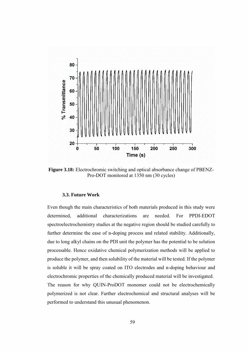
59
Figure 3.18: Electrochromic switching and optical absorbance change of PBENZ-Pro-DOT monitored at 1350 nm (30 cycles)
3.3. Future Work
Even though the main characteristics of both materials produced in this study were
determined, additional characterizations are needed. For PPDI-EDOT
spectroelectrochemistry studies at the negative region should be studied carefully to
further determine the ease of n-doping process and related stability. Additionally,
due to long alkyl chains on the PDI unit the polymer has the potential to be solution
processable. Hence oxidative chemical polymerization methods will be applied to
produce the polymer, and then solubility of the material will be tested. If the polymer
is soluble it will be spray coated on ITO electrodes and n-doping behaviour and
electrochromic properties of the chemically produced material will be investigated.
The reason for why QUIN-ProDOT monomer could not be electrochemically
polymerized is not clear. Further electrochemical and structural analyses will be
performed to understand this unusual phenomenon.

60
The preliminary results for PBENZ-Pro-DOT showed promising optical contrast and
switching time values. The film thickness optimization will be performed to
determine the highest optical contrast that can be achieved with this material.
Additionally, coloration efficiency of the material will be investigated. As mentioned
before PBENZ-Pro-DOT is decorated with long alkyl chains hence it expected to be
a solution processable material. Hence the corresponding monomer will be
polymerized under oxidative chemical polymerization conditions (ex: FeCl3,
EtOAc). The resulting polymer will be reduced and purified. Then the material will
be applied to ITO electrodes with spray coating and the electrochromic properties of
the resulting material will be investigated in detail.
61
CHAPTER 4
CONCLUSION
Three novel conjugated polymers were designed and synthesized towards reaching
two main targets: Realization of an easily dopable and stable n-type material and
realization of next generation green to transmissive electrochromic polymers with
enhanced properties. For the aim of stable n-type materials, PPDI-EDOT was
successfully synthesized and shown to be doped in an n-type manner by both
electrochemical and spectral means. Unusually low (absolute) voltages were
required for this doping process which clearly indicated the ease of n-doping in this
system. Accordingly, it is expected that stability of the n-type state should be
superior compared to classical examples of donor-acceptor type polymers which
require much higher voltages for the n-doping process. Interestingly the polymer was
produced by electrochemical polymerization which is quite rare for true n-type
materials with extremely low voltage requirements. Further analysis of this quite
interesting system is currently underway. For the aim of realizing next generation
green to transmissive electrochromic polymers two novel materials were designed
and synthesized successfully. Previous work from our group established the design
strategy for green to transmissive polymers. Most of these materials utilized EDOT
as the donor unit. It has been shown that ProDOT homopolymer outperforms
PEDOT. However, it has been shown that while benzothiadiazole-EDOT couple
gives a true green color, benzothiadiazole-ProDOT couple is cyan. The absorption
maxima are generally blue shifted when EDOT is exchanged with ProDOT. Here we
envisioned that switching benzothiadiazole with benzooxadiazole or quinaxaline
might result in a better donor-acceptor match towards the realization of a green to
transmissive polymer with superior properties. Unfortunately, and surprisingly, in
the case of quinoxaline substitution an electroactive polymer could not be produced.
In the case of benzooxadiazole substation and an electroactive polymer was
produced by means of electrpolymerization. Polymer revealed two absorption bands
62
as expected from a donor-acceptor material which were centered at 400 nm and 720
nm. Even though absorption centered at 720 nm is quite good for having a green
color the absorption band centered at 400 is not appropriate. For observing a green
color the lower wavelength band should be centered between 430-450 nm range.
Additionally, there was a quite big mismatch between the absorption intensities of
the two peaks. This resulted in observation of a blueish-green color in the neutral
state. The preliminary studies on the electrochromic properties of the material was
promising where a 30% optical contrast was achieved in the visible region with less
than 2 seconds switching times.
63
REFERENCES
[1] S. C. Rasmussen. Electrically Conducting Plastics: Revising the History of
Conjugated Organic Polymers. In 100+ years of plastics; Strom, T., Rasmussen. S.
C., Eds.; American Chemical Society: Washington D.C., 2011.; pp 147-163.
[2] H. Shirakawa, Rev. Mod. Phys. 2001, 73, 713-718.
[3] N. Miyaura, K. Yamada, A. Suzuki, Tetrahedron Lett. 1979, 20(36), 3437-3340.
[4] W. A. Gazotti, A. F. Nogueira, E. M. Girotto, L. Micaroni, M. Martini, S. das
Neves, M. De Paoli, Adv. Mater. 1998, 10, 60-64.
[5] J. L. Brédas, R. R. Chance, R. Silbey, Phys. Rev. B. 1982, 26, 5843-5854.
[6] J. L. Brédas, J. C. Scott, K. Yakushi, G. B. Street, Phys. Rev. B. 1984, 30, 1023-
1025.
[7] J. L. Reddinger, J.R. Reynolds, Adv. Polym. Sci. 1999, 145, 57-122.
[8] K.-Y. Jen, M. R. Maxfield, L. W. Shacklette, R. L. Elsenbaumer, J. Chem. Soc.,
Chem Comm. 1987, 4, 309-311.
[9] R. J. Waltman, J. Bargon, A. F. Diaz, J. Phys. Chem. 1983, 87, 1459-1463.
[10] J. M. Toussaint, J. L. Brédas, Synth. Met, 1993, 61, 103-106.
[11] J. Roncali, R. Garreau, A. Yassar, P. Marque, F. Garnier, M. Lemaire, J. Phys.
Chem. 1987, 91, 6706-6714.
[12] R. D. McCullough, Adv. Mater. 1998, 10, 93-116.
[13] H. Sirringhaus, P. J. Brown, R. H. Friend, M. M. Nielsen, K. Bechgaard, B. M.
W. Langeveld-Voss, A. J. H. Spiering, R. A. J. Janssen, E. W. Meijer, P. Hervig, D.
M. de Leeuw, Nature 1999, 401, 685-688.
[14] L. Groenendaal, F. Jonas, D. Freitag, H. Pielartzik, J. R. Reynolds, Adv. Mater.
2000, 12, 481-494.
[15] S. Kirchmeyer, K. Reuter, J. Mater. Chem. 2005, 15, 2077-2088.
[16] J. Roncali, Macromol. Rapid Commun. 2007, 28, 1761–1775.
[17] U. Salzner, J. Phys. Chem. B. 2002, 106, 9214-9220.
[18] D. M. de Leeuw, M. M. J. Simenon, A. R. Brown, R. E. F. Einerhand, Synth.
Met. 1997, 87, 53-59.
64
[19] Y. Takeda, T. L. Andrew, J. M. Lobez, A. J. Mork, T. M. Swager, Angew. Chem.
2012, 124, 9176 –9180.
[20] Z. A. Bao, A. J. Lovinger, J. Brown, J. Am. Chem. Soc. 1998, 120, 207–208.
[21] A. Facchetti, M.-H. Yoon, C. L. Stern, H. E. Katz, T. J. Marks, Angew. Chem.,
Int. Ed. Engl. 2003, 42, 3900-3903.
[22] M. Mamada, H. Shima, Y. Yoneda, T. Shimano, N. Yamada, K. Kakita, T.
Machida, Y. Tanaka, S. Aotsuka, D. Kumaki, S. Tokito, Chem. Mater. 2015, 27, 141-
147.
[23] A. R. Brown, S. M. de Leeuw, E. J. Lous, E. E. Havinga, Synth. Met. 1994, 66,
257–261.
[24] B. A. Jones, A. Facchetti, T. J. Marks, M. R. Wasielewski, Chem. Mater. 2007,
19, 2703–2705.
[25] G. Horowitz, F. Kouki, P. Spearman, D. Fichou, C. Nogues, X. Pan, F. Garnier,
Adv. Mater. 1996, 8, 242–245.
[26] H. E. Katz, A. J. Lovinger, J. Johnson, C. Kloc, T. Siegrist, W. Li, Y. Y. Lin, A.
Dodabalapur, Nature 2000, 404, 478–481.
[27] H. Li, F. S. Kim, G. Ren, E. C. Hollenbeck, S. Subramaniyan, S. A. Jenekhe,
Angew. Chem., Int. Ed. Engl. 2013, 52, 5513-5517.
[28] A. Babel, S. A. Jenekhe, J. Am. Chem. Soc. 2003, 125, 13656–13567.
[29] Z. Chen, Y. Zheng, H. Yan, A. Facchetti, J. Am. Chem. Soc. 2009, 131, 8–9.
[30] H. Yan, Z. Chen, Y. Zheng, C. Newman, J. R. Quinn, F. Dotz, M. Kastler, A.
Facchetti, Nature 2009, 457, 679–686.
[31] X. Guo, F. S. Kim, M. J. Seger, S. A. Jenekhe, M. D. Watson, Chem. Mater.
2012, 24, 1434–1442.
[32] H. Li, F. S. Kim, G. Ren, S. A. Jenekhe, J. Am. Chem. Soc. 2013, 135, 14920–
14923.
[33] J. Choi, H. Song, N. Kim, F. S. Kim, Semicond. Sci. Technol. 2015, 30, 064002.
[34] R. J. Mortimer, Chem Soc. Rev. 1997, 26, 147-156.
[35] S. K. Deb, Appl. Opt. Suppl. 1969, 3, 192-195.
[36] P. D. Beer, O. Kocian, R. J. Mortimer, C. Ridgway, J. Chem. Soc., Faraday
Trans. 1993, 89, 333-338.
65
[37] H. Byker, in Electrochromic Materials 11, Ho, K.-C., MacArthur, D. A., Eds.,
Electrochem. Soc. Proc. Ser. Pennington: New Jersey, 1994.
[38] M. Green, Chem. Ind. 1996, 17, 641-644.
[39] A. Kraft, Bull. Hist. Chem. 2008, 33, 61-67.
[40] P. M. S. Monk, R. J. Mortimer, D. R. Rosseinsky, Electrochromism:
Fundamentals and Applications, VCH: New York, 1995.
[41] J. J. Berzelius, Afb. Fys. Kemi Miner. 1815, 4, 293.
[42] F. Wöhler, Ann. Phys. 1824, 2, 350-358.
[43] P. M. S. Monk, R. J. Mortimer, D. R. Rosseinsky, Electrochromism and
Electrochromic Devices, Cambridge Univ. Press: Cambridge, 2007.
[44] C. G. Granqvist, Handbook of Inorganic Electrochromic Materials, Elsevier:
Amsterdam, 1995.
[45] T. A. Skotheim, J. R. Reynolds, Handbook of Conducting Polymers, CRC: Boca
Raton, 2007.
[46] J. Roncali, Chem. Rev., 1992, 92, 4, 711-738.
[47] A. L. Dyer, E. J. Thompson, J. R. Reynolds, ACS Appl. Mater. Interfaces 2011,
3, 1787–1795.
[48] C. M. Amb, J. A. Kerszulis, E. J. Thompson, A. L. Dyer, J. R. Reynolds, Polym.
Chem. 2011, 2, 812-814.
[49] R. C. Gonzalez, R. E. Woods, Digital Image Processing, Addison-Wesley, 1993.
[50] W. K. Pratt, Digital Image Processing, John Wiley & Sons: New York, 1991.
[51] C. Ponyton, Digital Video and HD: Algorithms and Interfaces, San Francisco:
Elsevier, 2003.
[52] N. Boughen, Lightwave 3D 7.5 Lighting, Wordware Publishing: Texas, 2003
[53] T. Deutschmann, S. Roth, E. Oesterschulze, J. Micromech. Microeng. 2013, 23,
065032.
[54] A. Balan, G. Gunbas, A. Durmus, L. Toppare, Chem. Mater. 2008, 20, 7510-
7513.
[55] B. Karabay, L. C. Pekel, Atilla Cihaner, Macromolecules 2015, 48, 1352-1357.
[56] M. I. Ozkut, S. Atak, A. M. Onal, A. Cihaner, J. Mater. Chem. 2011, 21,
5268-5272.
[57] C. M. Amb, P. M. Beaujuge, J. R. Reynolds, Adv. Mater. 2010, 22, 724-728.
66
[58] R. Yuksel, E. Ataoglu, J. Turan, E. Alpugan, S. O. Hacioglu, L. Toppare, A.
Cirpan, H. E. Unalan, G. Gunbas, J. Polym. Sci., Polym. Chem. 2017, 55, 1680–1686.
[59] G. Sonmez, C. K. F. Shen, F. Rubin, F. Wudl, Angew. Chem., Int. Ed. 2004, 43,
1498-1502.
[60] A. Durmus, E. G. Gunbas, P. Camurlu, L. Toppare, Chem. Commun. 2007, 3246-
3248.
[61] G. Gunbas, A. Durmus, L. Toppare, Adv. Mater. 2008, 20, 691-695.
[62] G. Gunbas, A. Durmus, L. Toppare, Adv. Funct. Mater. 2008, 18, 2026-2030.
[63] P. M. Beaujuge, S. Ellinger, J. R. Reynolds, Adv. Mater. 2008, 20, 2772-2776.
[64] A. L. Dyer, M. R. Craig, J. E. Babiarz, K. Kiyak, J. R. Reynolds,
Macromolecules, 2010, 43, 4460-4467.
[65] X. Chen, Z. Xu, S. Mi, J. Zhenga, C. Xu, New J. Chem. 2015, 39, 5389-5394.
[66] Z. Xu, X. Chen, S. Mi, J. Zheng, C. Xu, Org. Electron. 2015, 26, 129-136.
[67] G. Atakana, G. Gunbas, RSC Adv. 2016, 6, 25620–25623.
[68] J. Roncali, Chem. Rev. 1997, 97, 173-206.
[69] F. Babudri, G. M. Farinola, F. Nasa, R. Ragni, Chem. Commun. 2007, 1003-
1022.
[70] M. Losurdo, M. M. Giangregorio, P. Capezzuto, A. Cardone, C. Martinelli, G.
M. Farinola, F. Babudri, F. Naso, M. Büchel, G. Bruno, Adv. Mater. 2009, 21, 1115-
1120.
[71] R. J. Mortimer, Electrochim. Acta. 1999, 44, 2971-2981.
[72] J. C. Lacroix, K. K. Kanazawa, A. J. Diaz, Electrochem. Soc. 1989, 136, 1308-
1313.
[73] J.-C. Ching, A. G. MacDiarmid, Synth. Met. 1986, 13, 193-205.
[74] D. M. Welsh, A. Kumar, E. W. Meijer, J. R. Reynolds, Adv. Mater. 1999, 11,
1379-1382.
[75] C. L. Gaupp, K. Zong, P. Schottland, B. C. Thompson, J. R. Reynolds,
Macromolecules, 2000, 33, 1132-1133.
[76] P. Schottland, K. Zong, C. L. Gaupp, B. C. Thompson, C. A. Thomas, I. Giurgiu,
R. Hickman, K. A. Abboud, J. R. Reynolds, Macromolecules 2000, 33, 7051-7061.
[77] G. Sonmez, I. Schwendeman, P. Schottland, K. Zong, J. R. Reynolds,
Macromolecules 2003, 36, 639-647.
67
[78] G. A. Sotzing, J. L. Reddinger, A. R. Katritzky, J. Soloducho, R. Musgrave, J. R.
Reynolds, Chem. Mater. 1997, 9, 1578-1587.
[79] D. J. Irvin, C. J. DuBois, J. R. Reynolds, Chem. Commun. 1999, 2121-2122.
[80] C. J. DuBois, J. R. Reynolds, Adv. Mater. 2002, 14, 1844-1846.
[81] A. A. Argun, P.-H. Aubert, B. C. Thompson, I. Schwendeman, C. L. Gaupp, J.
Hwang, N. J. Pinto, D. B. Tanner, A. G. MacDiarmid, J. R. Reynolds, Chem. Mater.
2004, 16, 4401-4412.
[82] D. Kumar, R. C. Sharma, Eur. Polym. J. 1998, 34, 1053-1060.
[83] S. Sadki, P. Schottland, N. Brodie, G. Sabouraud, Chem. Soc. Rev. 2000, 29, 283-
293.
[84] G. Zotti, Handbook of Organic Conductive Molecules and Polymers, Nalwa, H.
S. Eds., Wiley: Chichester, 1997.
[85] M. E. G. Lyons, Advances in Chemical Physics, Polymeric Systems, Prigogine,
I., Rice, S. A., John Wiley & Sons: New York, 1997.
[86] G. Zotti, G. Schiavon, A. Berlin, G. Pagani, Chem. Mater. 1993, 5, 430-436.
[87] P. Audebert, P. Hapiot, Synthetic Metal 1999, 75, 95.
[88] K. Yoshino, S. Hayashi, R. Sugimoto, Japanese Journal of Applied Physics 1984,
23, L899.
[89] N. Miyaura, A. Suzuki, Synth. Commun. 1981, 11, 513-519.
[90] T. Yokozawa, H. Kohno, Y. Ohta, A. Yokoyama, Macromolecules 2010, 43,
7095–7100.
[91] D. Milstein, J. K. Stille, J. Am. Chem. Soc. 1978, 100, 3636-3638.
[92] Z. Bao, W. Chan, L. Yu, Chem. Mater. 1993, 5, 2-3.
[93] T. Yamamoto, Chem. Lett. 2012, 41, 1422-1424.
[94] E. Knoevenagel, Chem. Ber. 1894, 27, 2345-2346.
[95] D. C. Forbes, Tetrahedron Letters 2006, 47, 1699–1703.
[96] J. Liao, Q. Wang, Macromolecules 2004, 37, 7061-7063.
[97] K. Tamao, M. Kumada, J. Am. Chem. Soc. 1972, 94, 4374-4392.
[98] J. P. Corriu, J. P. Masse, Chem. Commun. 1972, 144a.
[99] S. Murahashi, J. Organomet. Chem. 1975, 91, C39.
[100] K. Tamao, J. Organomet. Chem. 2002, 653, 23-26.
68
[101] S. Xu, E. H. Kim, A. Wei, E. Negishi, Sci. Technol. Adv. Mater. 2014,
15, 044201.
[102] K. Sonogashira, Y. Tohda, N. Hagihara, Tetrahedron Letters 1975, 50, 4467-
4470.
[103] L. B. Sessions, B. R. Cohen, R. B. Grubbs, Macromolecules 2007, 40, 1926-
1933.
[104] X. Guo, M. D. Watson, Org. Lett. 2008, 10, 5333-5336.
[105] E. Hussain, H. Zhou, N. Yang, S. A. Shahzad, C. Yu, Dyes and Pigment, 2017,
147, 211-224.
[106] S. Vajiravelu, L. Ramunas, G. J. Vidas, G. Valentas, J. Vygintasc, S.
Valiyaveetti, J. Mater. Chem. 2009, 4268–4275.
[107] C.-W. Ge, C.-Y. Mei, J. Ling, J.-T. Wang, F.-G. Zhao, L. Liang, H.-J. Li, Y.-S.
Xie, W.-S. Li, J. Polym. Sci., Polym. Chem. 2014, 52, 1200–1215.
[108] B. Jousselme, P. Blanchard, E. Levillain, R. de Bettignies, J. Roncali,
Macromolecules 2003, 36, 3020-3025.
[109] Y.-S. Shon, T. R. Lee, Langmuir 1999, 15, 1136-1140.
[110] X. Chen, B. Liu, Y. Zou, W. Tang, Y. Li, D. Xiao, RSC Adv. 2012, 2, 7439-
7448.
[111] M. Imit, P. Imin, A. Adronov, Polym. Chem. 2016, 7, 5241–5248.
[112] P. M. Beaujuge, S. V. Vasilyeva, D. Y. Liu, S. Ellinger, T. D. McCarley, J. R.
Reynolds, Chem. Mater. 2012, 24, 255-268.
[113] P. Camurlu, RSC Adv., 2014, 4, 55832–55845.
[114] P. I. Lee, S. L. C. Hsu, P. Lin, Macromolecules 2010, 43, 8051-8057.
[115] A. V. Patil, W. H. Lee, E. Lee, K. Kim, I. N. Kang, S. H. Lee, Macromolecules
2011, 44, 1238-1241.
[116] G. Gunbas, L. Toppare, Chem. Commun. 2012, 48, 1083–1101.
69
APPENDICES
A. NMR Spectra of Synthesized Monomers
Fig
ure
A.1
.1:
1 H-N
MR
spec
trum
2-d
ecyl
-1-te
trade
cylb
rom
ide
70
Fig
ure
A.1
.2:
13C
-NM
R sp
ectru
m o
f 2-
decy
l-1-te
trade
cylb
rom
ide
71
Fig
ure
A.2
.1: 1
H-N
MR
spec
trum
N-(
2-de
cylte
trade
cyl)p
hath
alim
ide
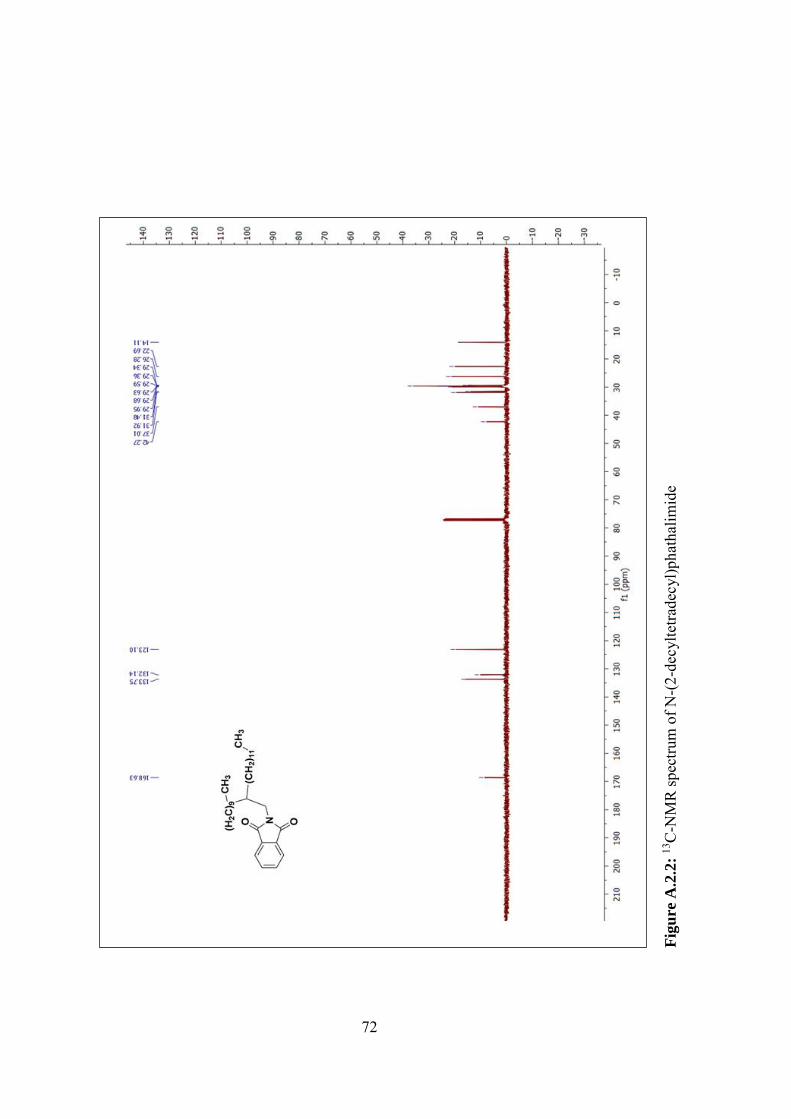
72
Fig
ure
A.2
.2:
13C
-NM
R sp
ectru
m o
f N-(
2-de
cylte
trade
cyl)p
hath
alim
ide
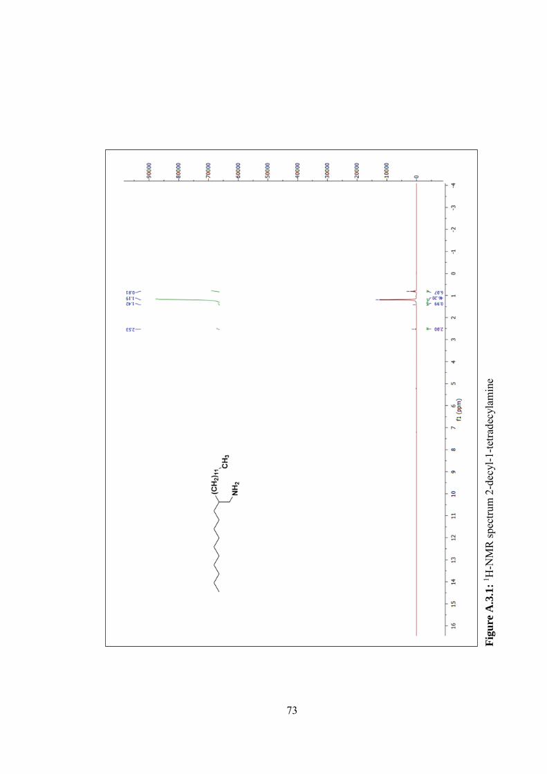
73
Fig
ure
A.3
.1:
1 H-N
MR
spec
trum
2-d
ecyl
-1-te
trade
cyla
min
e
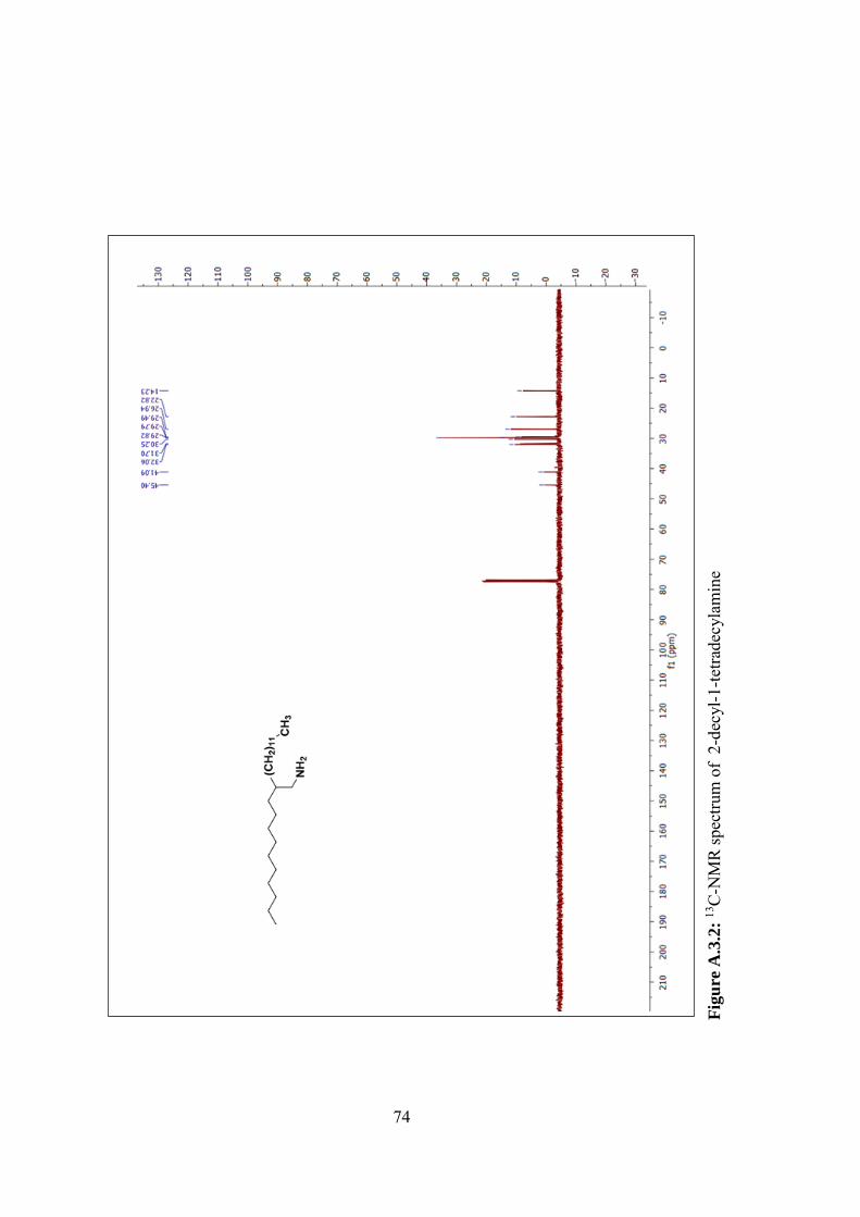
74
Fig
ure
A.3
.2:
13C
-NM
R sp
ectru
m o
f 2-
decy
l-1-te
trade
cyla
min
e
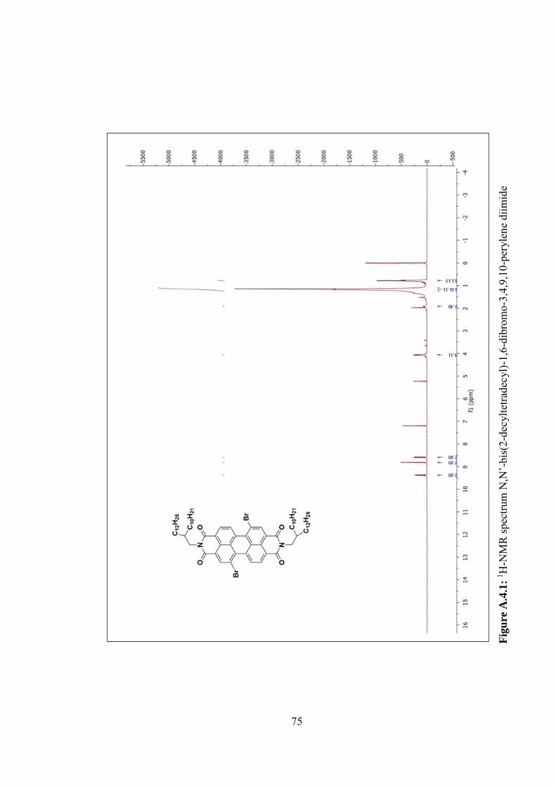
75
Fig
ure
A.4
.1:
1 H-N
MR
spec
trum
N,N
’-bi
s(2-
decy
ltetra
decy
l)-1,
6-di
brom
o-3,
4,9,
10-p
eryl
ene
diim
ide
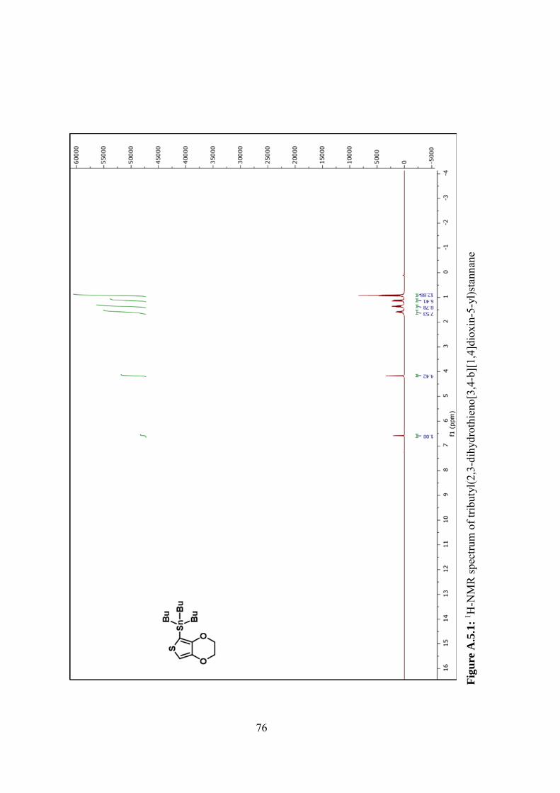
76
Fig
ure
A.5
.1:
1 H-N
MR
spec
trum
of t
ribut
yl(2
,3-d
ihyd
roth
ieno
[3,4
-b][
1,4]
diox
in-5
-yl)s
tann
ane
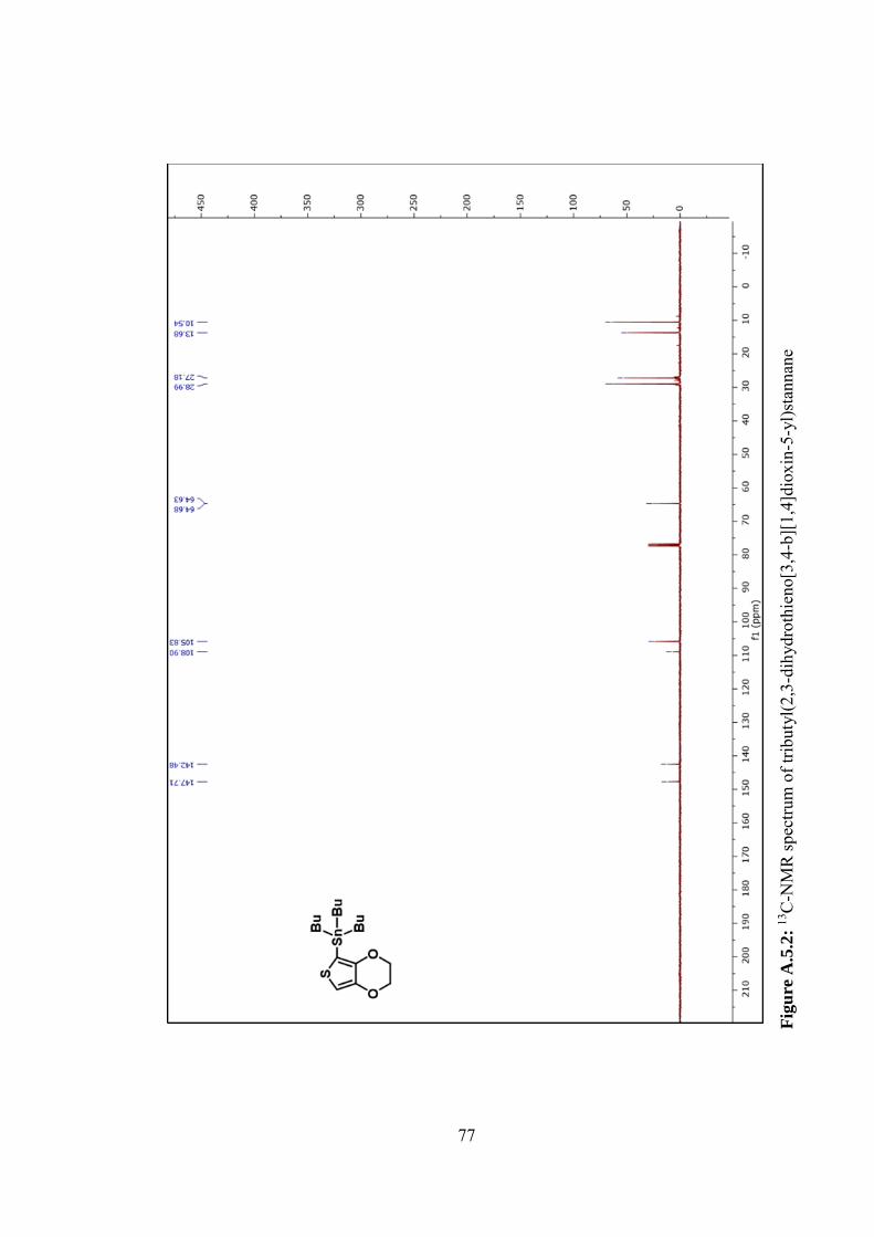
77
Fig
ure
A.5
.2:
13C
-NM
R sp
ectru
m o
f trib
utyl
(2,3
-dih
ydro
thie
no[3
,4-b
][1,
4]di
oxin
-5-y
l)sta
nnan
e
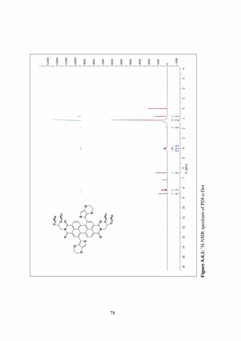
78
Fig
ure
A.6
.1:
1 H-N
MR
spec
trum
of P
DI-
e-D
ot
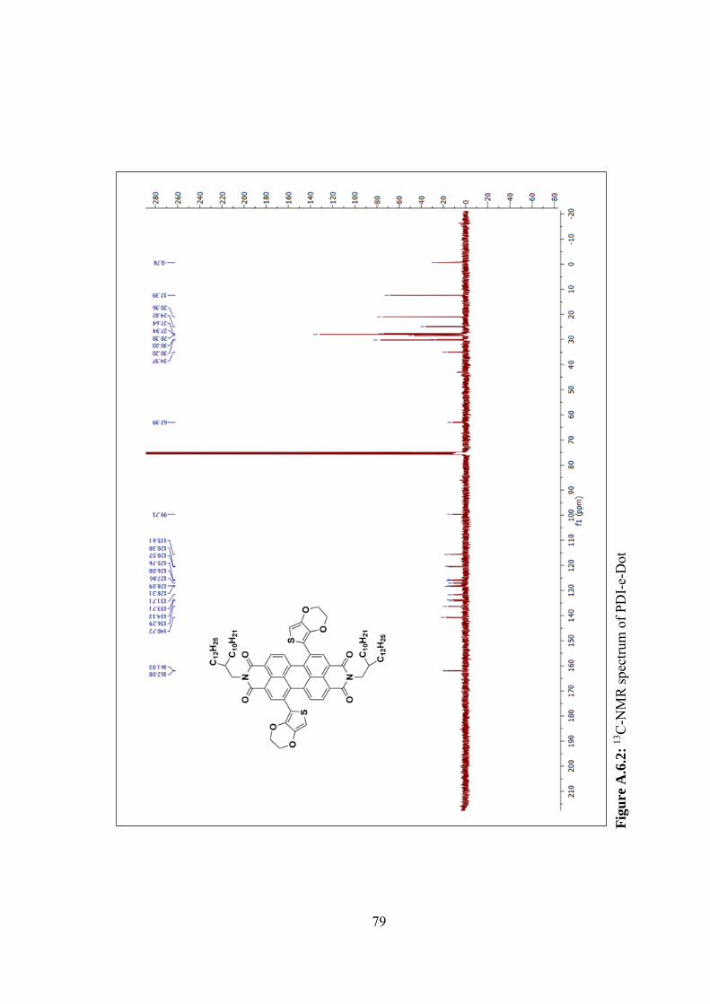
79
Fig
ure
A.6
.2:
13C
-NM
R sp
ectru
m o
f PD
I-e-
Dot
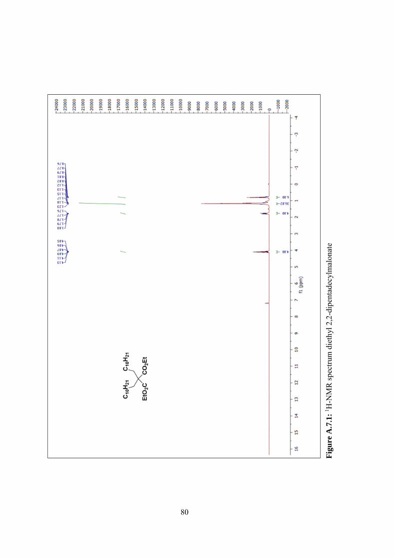
80
Fig
ure
A.7
.1:
1 H-N
MR
spec
trum
die
thyl
2,2
-dip
enta
decy
lmal
onat
e
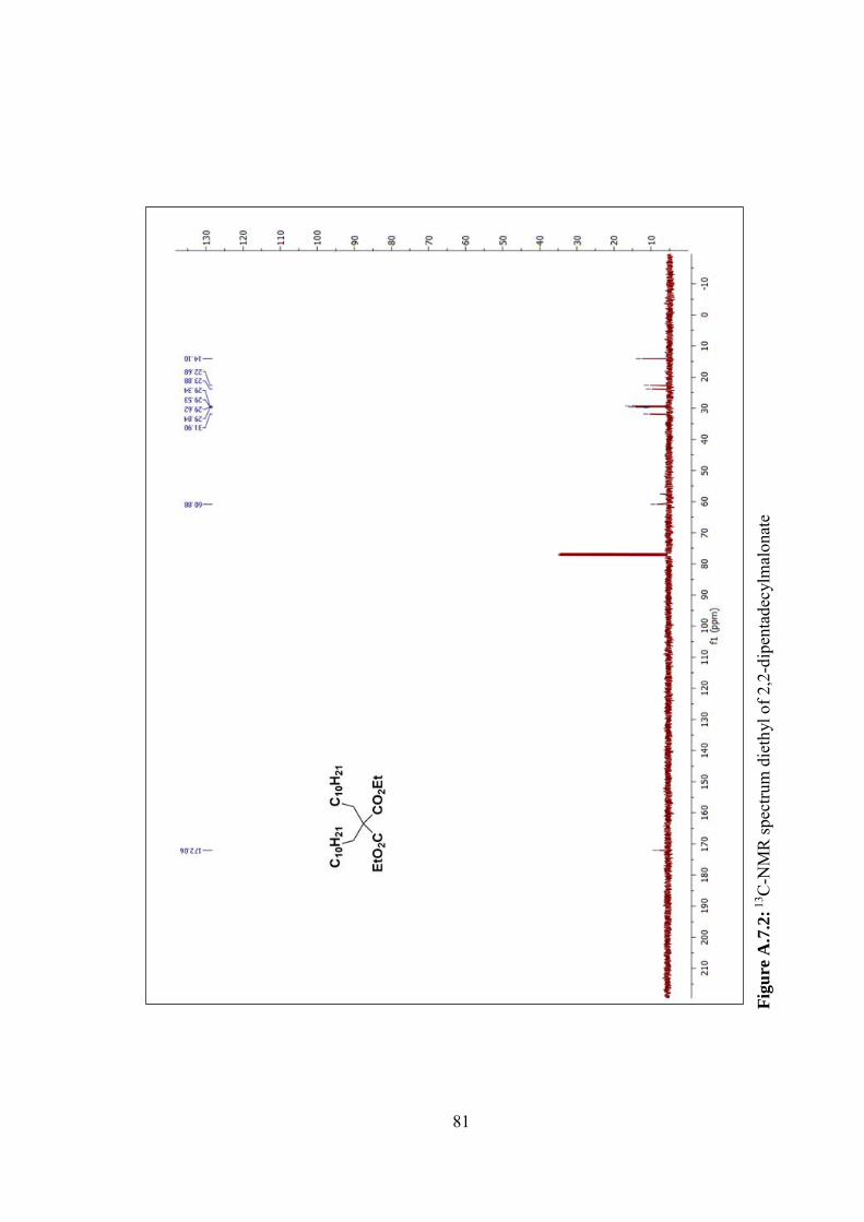
81
Fig
ure
A.7
.2: 1
3 C-N
MR
spec
trum
die
thyl
of 2
,2-d
ipen
tade
cylm
alon
ate
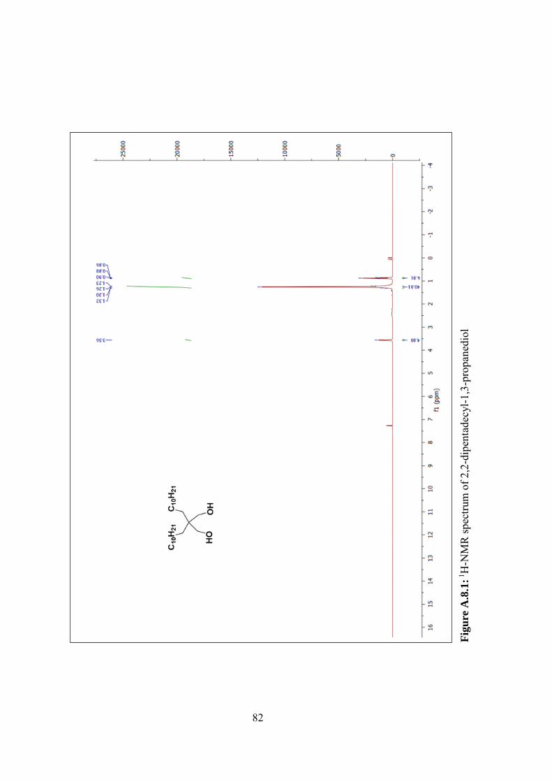
82
Fig
ure
A.8
.1: 1
H-N
MR
spec
trum
of 2
,2-d
ipen
tade
cyl-1
,3-p
ropa
nedi
ol
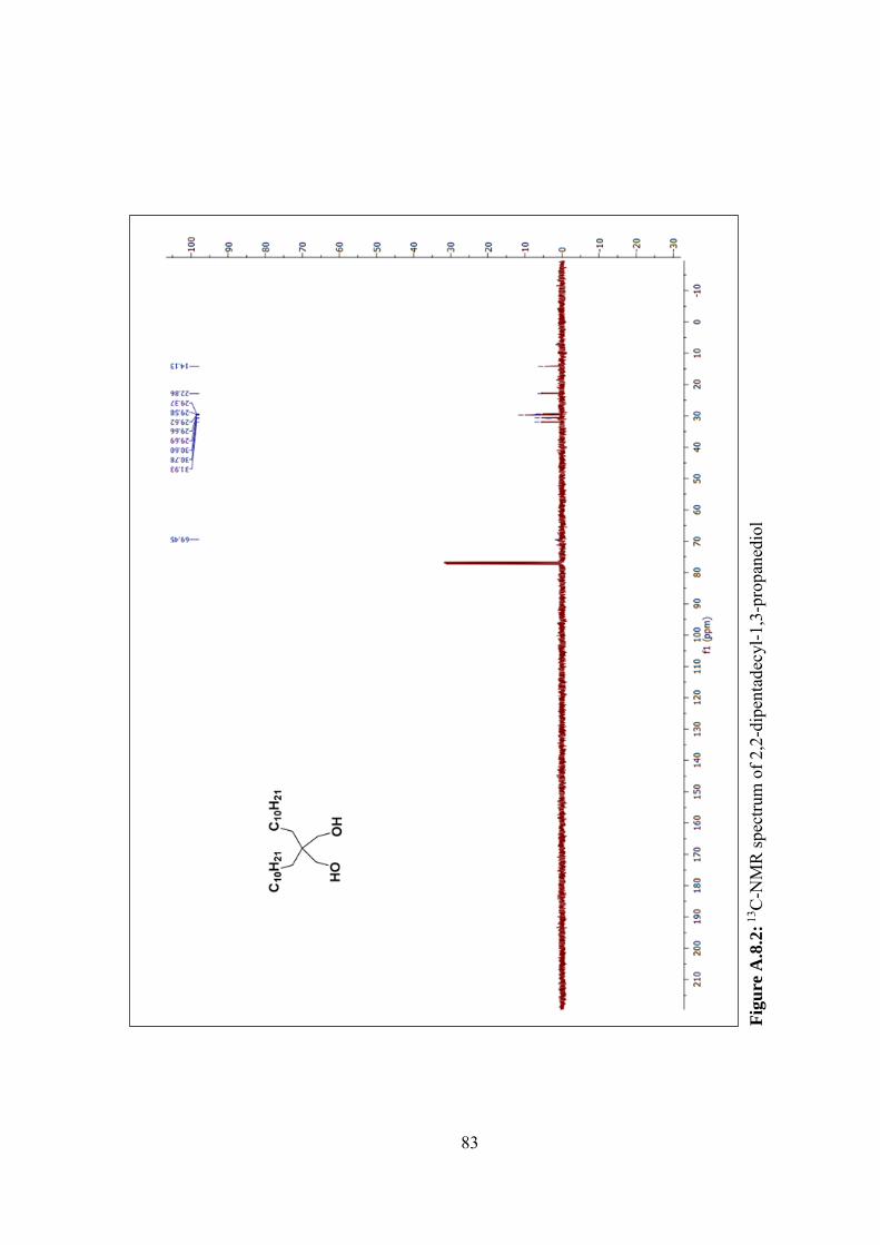
83
Fig
ure
A.8
.2: 1
3 C-N
MR
spec
trum
of 2
,2-d
ipen
tade
cyl-1
,3-p
ropa
nedi
ol
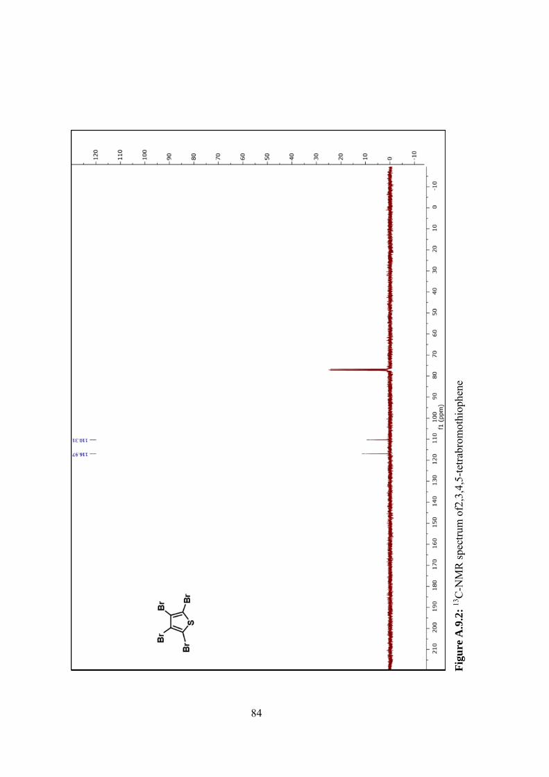
84
Fig
ure
A.9
.2:
13C
-NM
R sp
ectru
m o
f2,3
,4,5
-tetra
brom
othi
ophe
ne
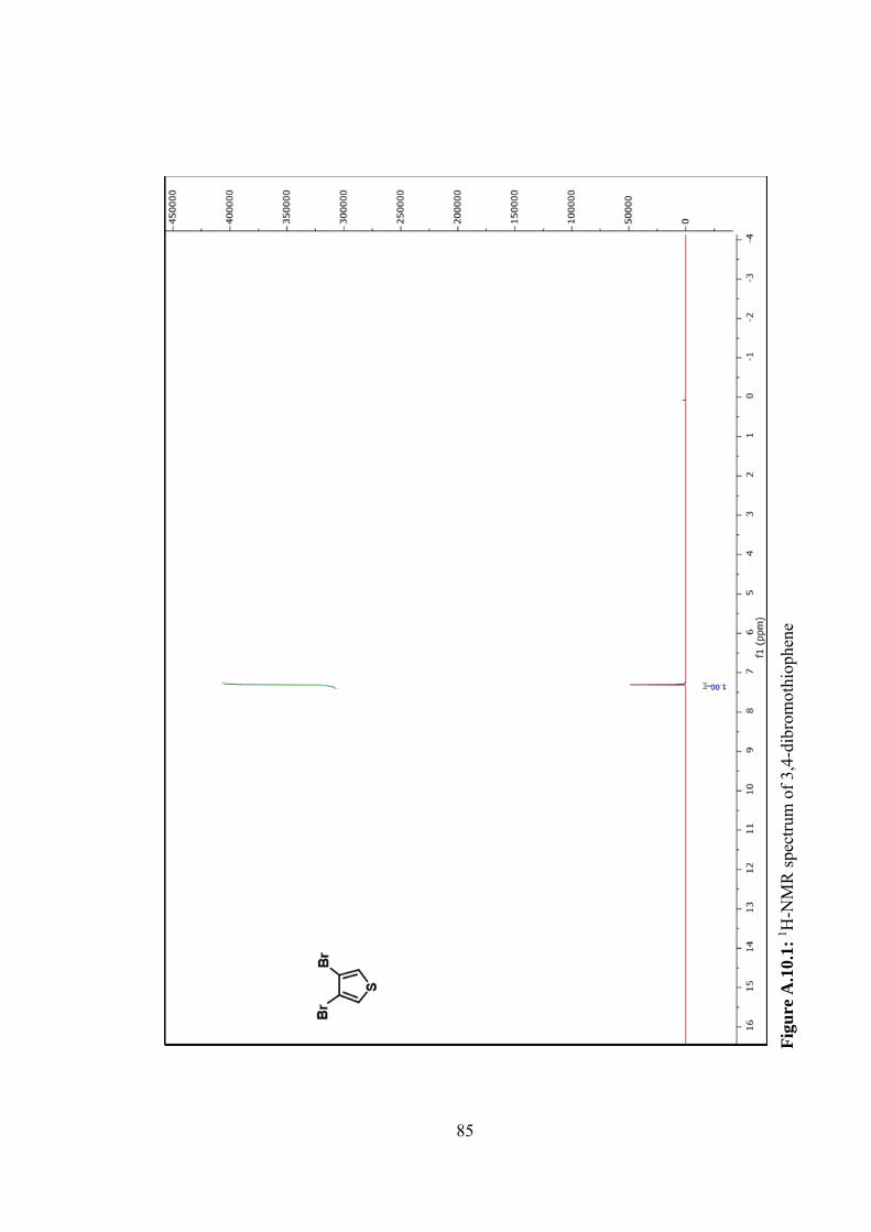
85
Fig
ure
A.1
0.1
: 1 H
-NM
R sp
ectru
m o
f 3,4
-dib
rom
othi
ophe
ne
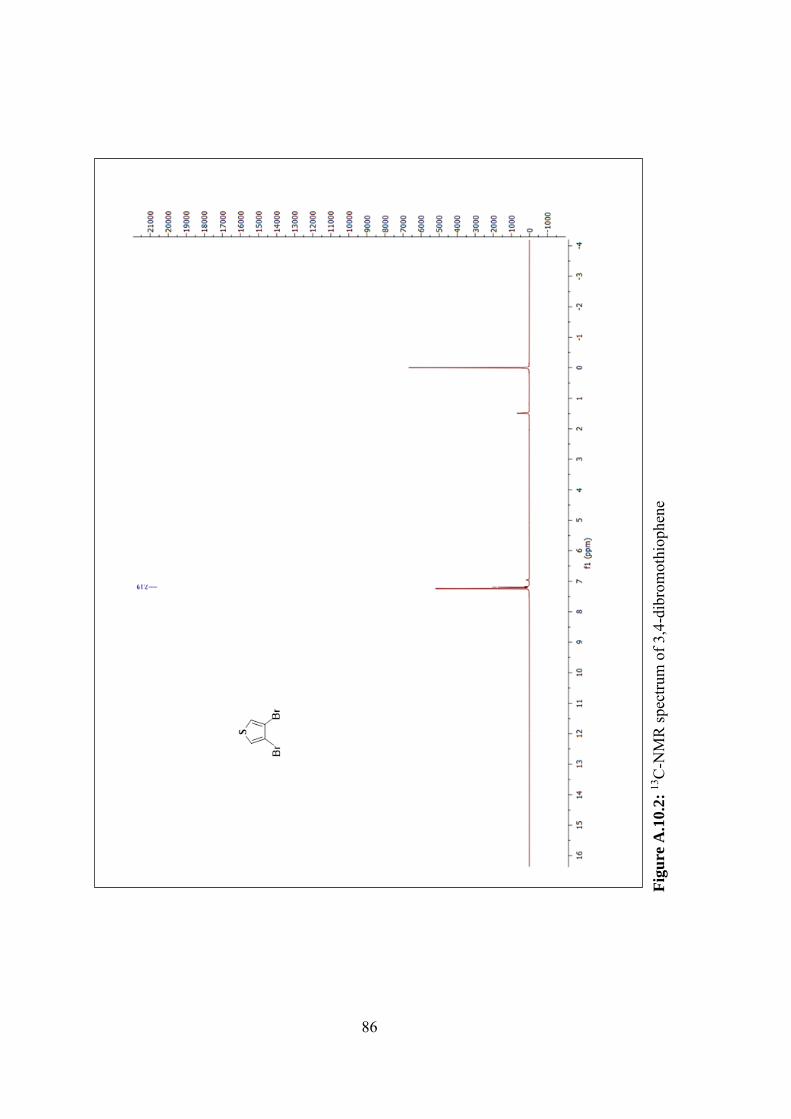
86
Fig
ure
A.1
0.2
: 13
C-N
MR
spec
trum
of 3
,4-d
ibro
mot
hiop
hene
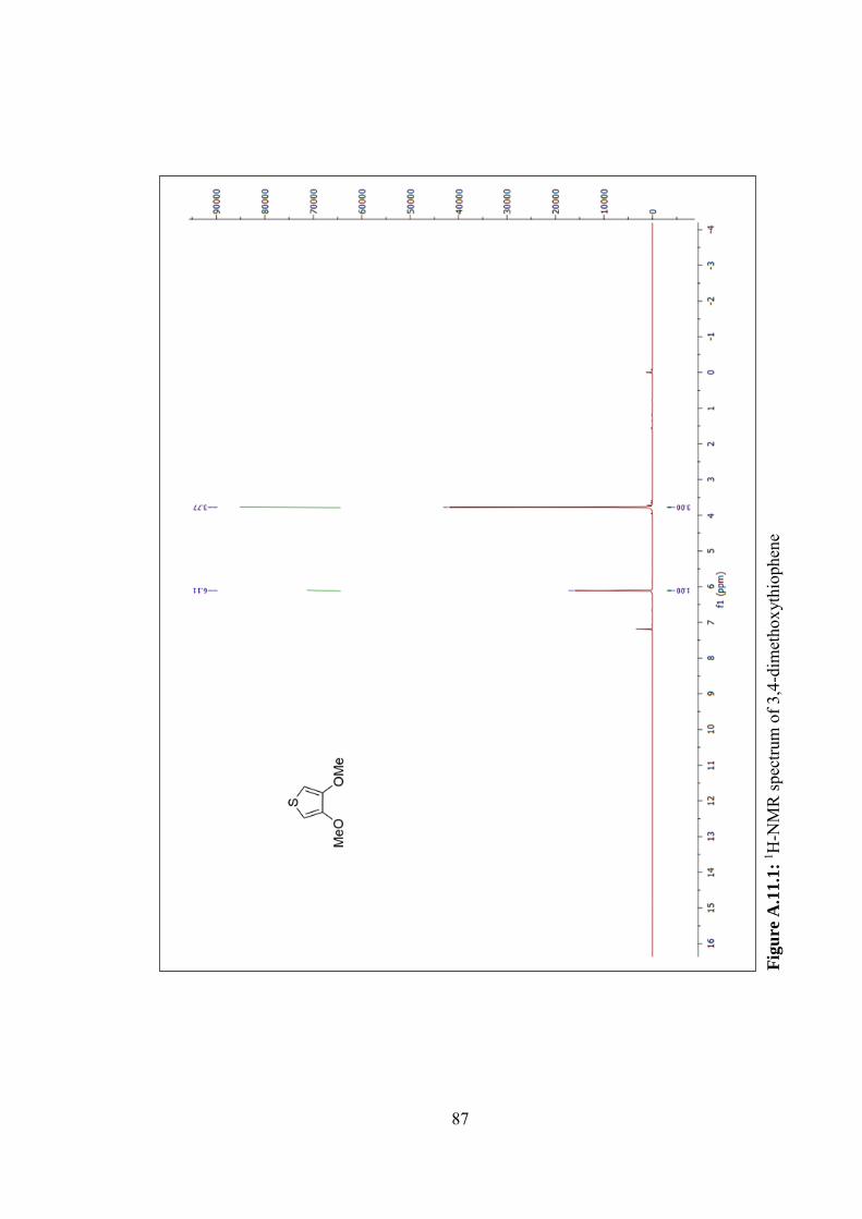
87
Fig
ure
A.1
1.1
: 1 H
-NM
R sp
ectru
m o
f 3,4
-dim
etho
xyth
ioph
ene
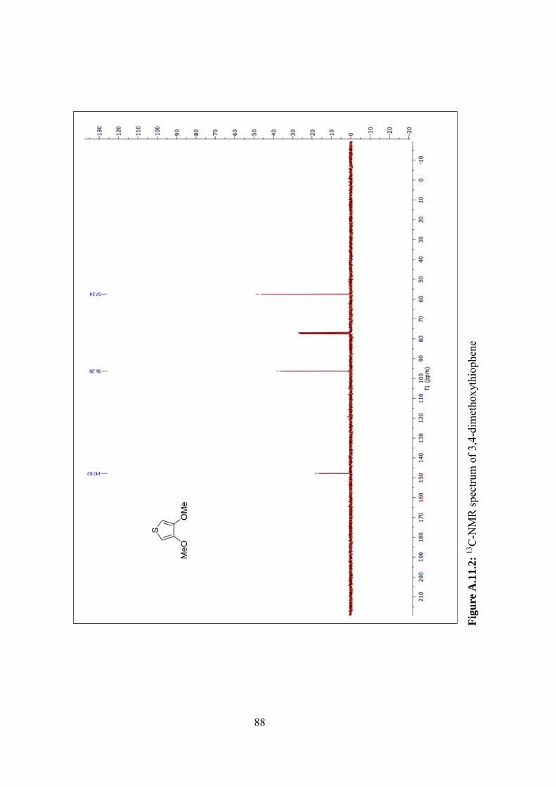
88
Fig
ure
A.1
1.2
: 13
C-N
MR
spec
trum
of 3
,4-d
imet
hoxy
thio
phen
e
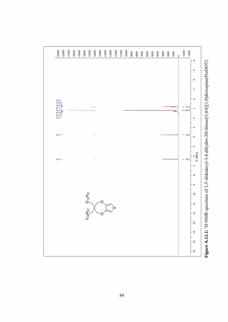
89
Fig
ure
A.1
2.1
: 1H
-NM
R sp
ectru
m o
f 3,3
'-did
odec
yl-3
,4-d
ihyd
ro-2
H-th
ieno
[3,4
-b][
1,4]
diox
epin
e(Pr
oDO
T)
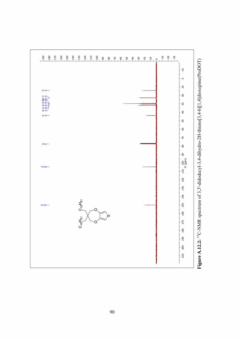
90
Fig
ure
A.1
2.2
: 13
C-N
MR
spec
trum
of 3
,3'-d
idod
ecyl
-3,4
-dih
ydro
-2H
-thie
no[3
,4-b
][1,
4]di
oxep
ine(
ProD
OT)
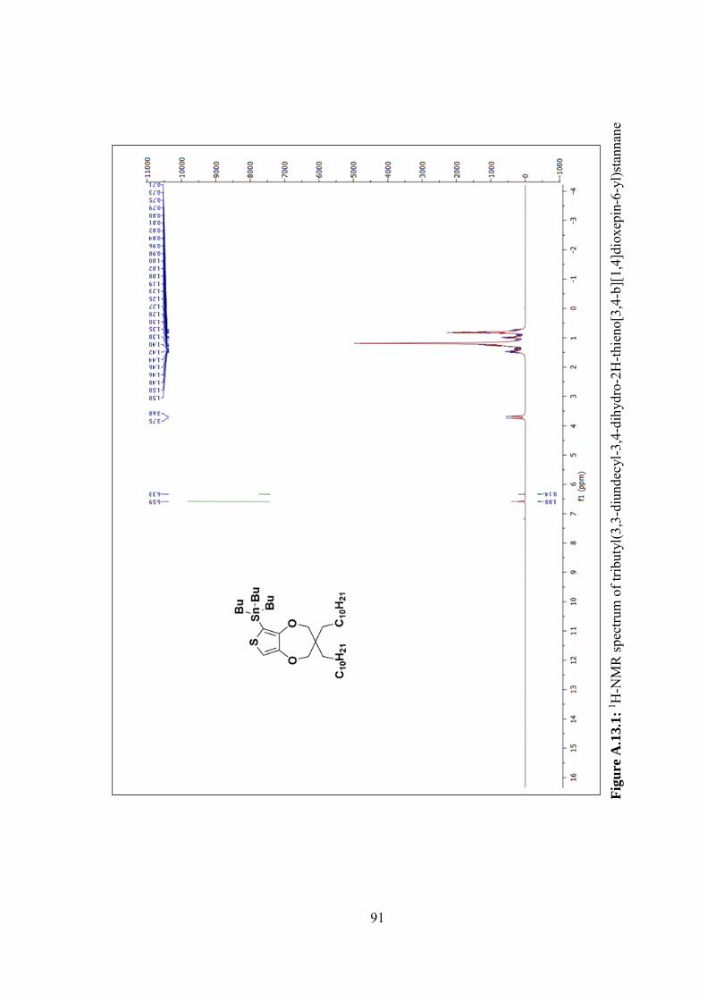
91
Fig
ure
A.1
3.1
: 1 H
-NM
R sp
ectru
m o
f trib
utyl
(3,3
-diu
ndec
yl-3
,4-d
ihyd
ro-2
H-th
ieno
[3,4
-b][
1,4]
diox
epin
-6-y
l)sta
nnan
e
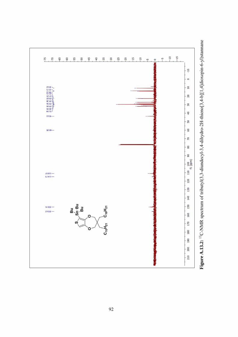
92
Fig
ure
A.1
3.2
: 13
C-N
MR
spec
trum
of t
ribut
yl(3
,3-d
iund
ecyl
-3,4
-dih
ydro
-2H
-thie
no[3
,4-b
][1,
4]di
oxep
in-6
-yl)s
tann
ane
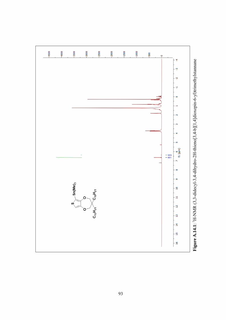
93
Fig
ure
A.1
4.1
: 1 H-N
MR
(3,3
-did
ecyl
-3,4
-dih
ydro
-2H
-thie
no[3
,4-b
][1,
4]di
oxep
in-6
-yl)t
rimet
hyls
tann
ane
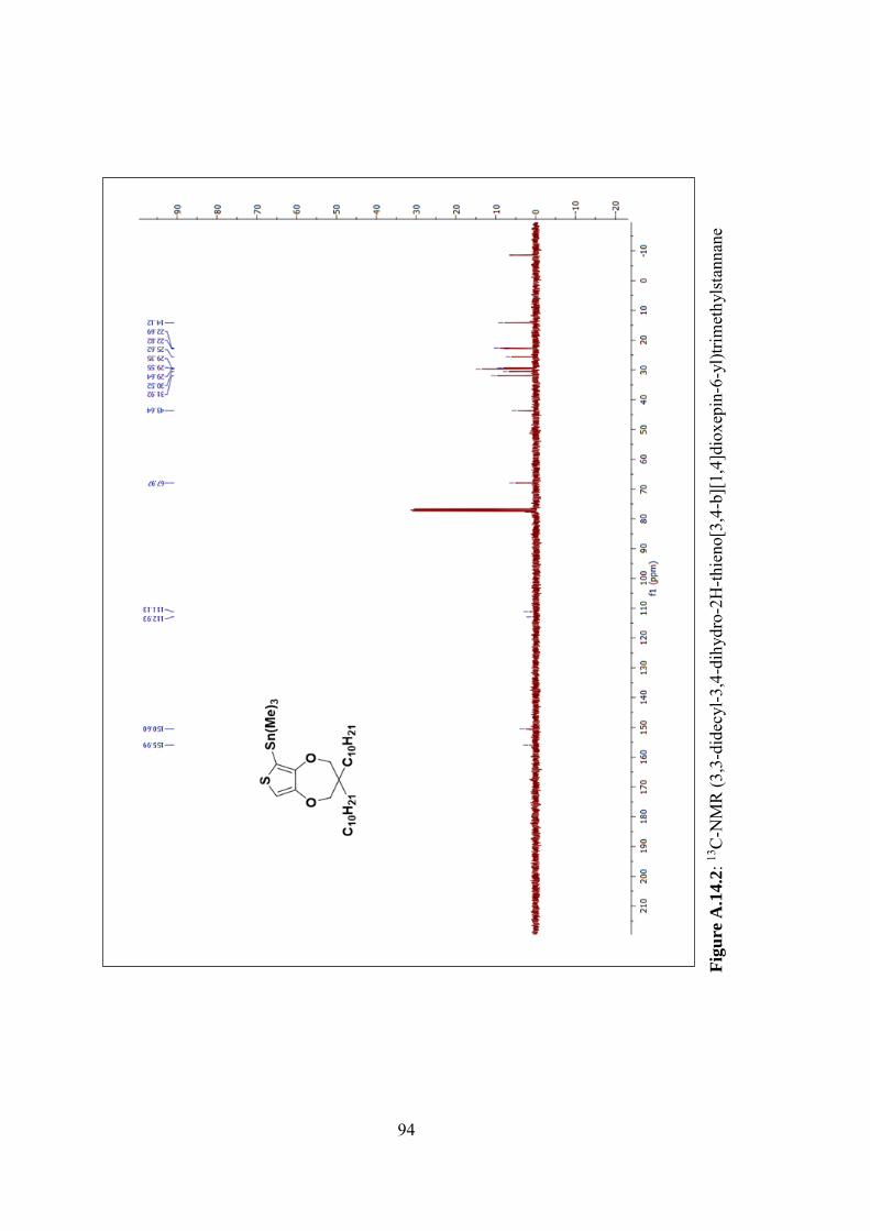
94
Fig
ure
A.1
4.2
: 13C
-NM
R (3
,3-d
idec
yl-3
,4-d
ihyd
ro-2
H-th
ieno
[3,4
-b][
1,4]
diox
epin
-6-y
l)trim
ethy
lsta
nnan
e
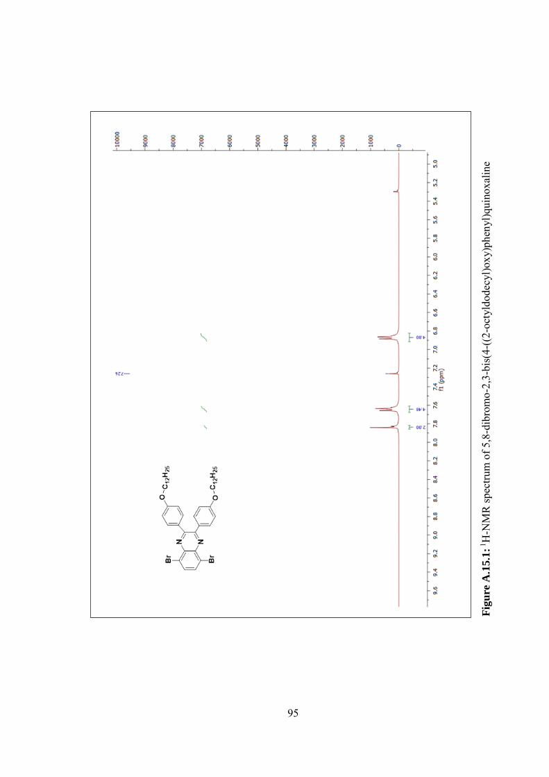
95
Fig
ure
A.1
5.1
: 1H
-NM
R sp
ectru
m o
f 5,8
-dib
rom
o-2,
3-bi
s(4-
((2-
octy
ldod
ecyl
)oxy
)phe
nyl)q
uino
xalin
e
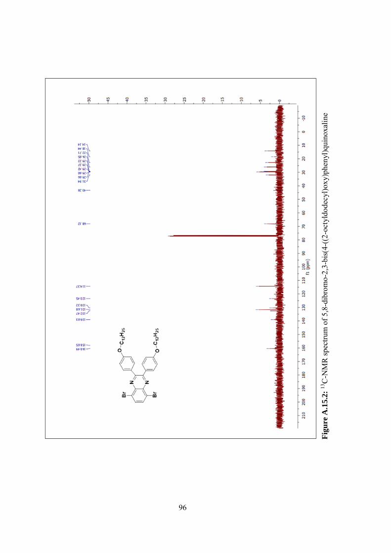
96
Fig
ure
A.1
5.2
: 13C
-NM
R sp
ectru
m o
f 5,8
-dib
rom
o-2,
3-bi
s(4-
((2-
octy
ldod
ecyl
)oxy
)phe
nyl)q
uino
xalin
e
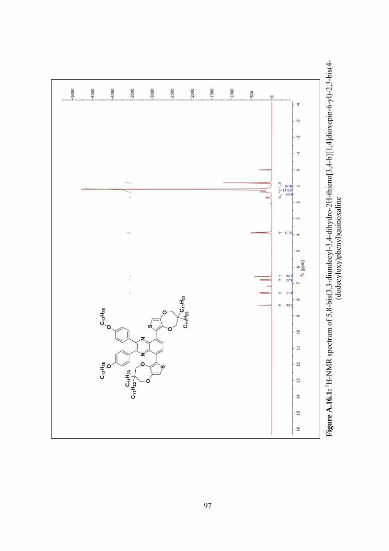
97
Fig
ure
A.1
6.1
: 1H
-NM
R sp
ectru
m o
f 5,8
-bis
(3,3
-diu
ndec
yl-3
,4-d
ihyd
ro-2
H-th
ieno
[3,4
-b][
1,4]
diox
epin
-6-y
l)-2,
3-bi
s(4-
(dod
ecyl
oxy)
phen
yl)q
uino
xalin
e
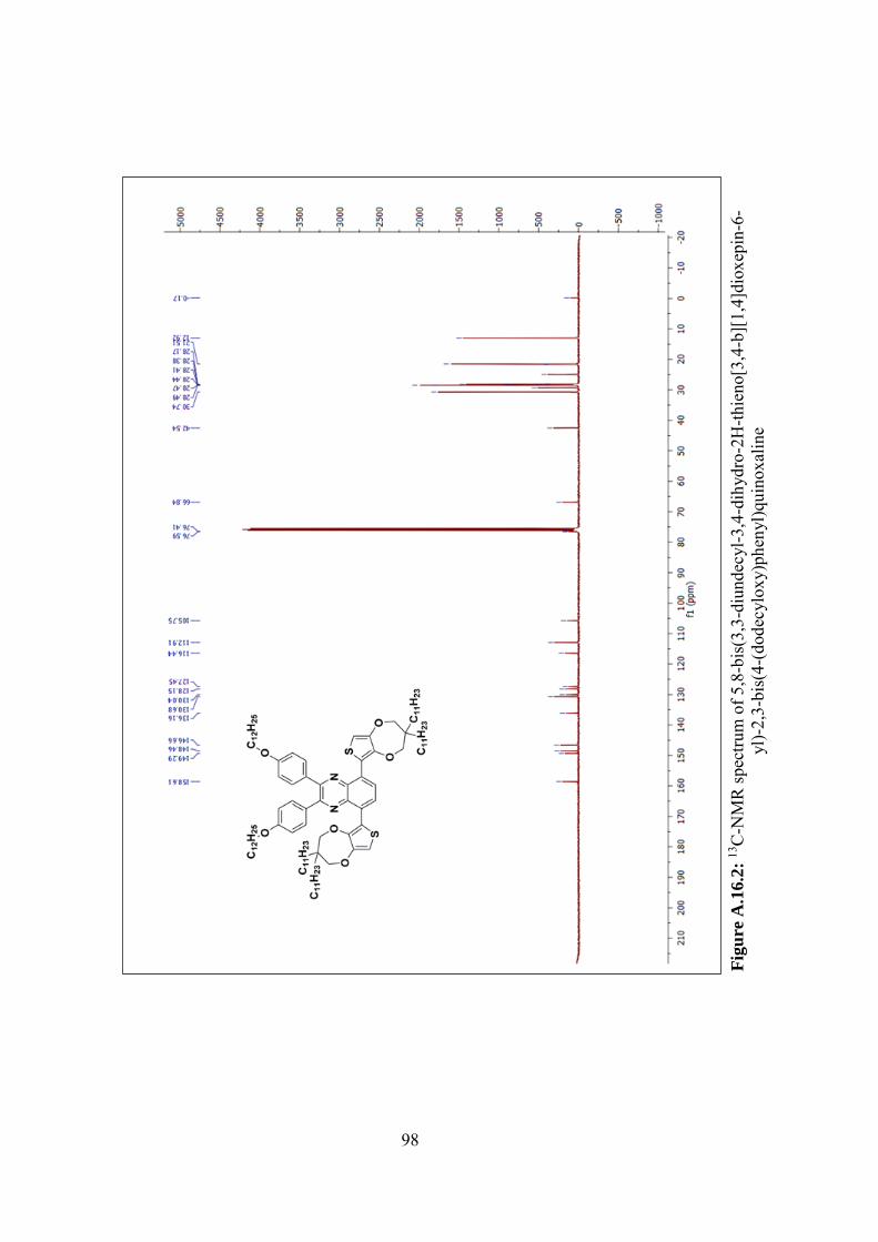
98
Fig
ure
A.1
6.2
: 13C
-NM
R sp
ectru
m o
f 5,8
-bis
(3,3
-diu
ndec
yl-3
,4-d
ihyd
ro-2
H-th
ieno
[3,4
-b][
1,4]
diox
epin
-6-
yl)-
2,3-
bis(
4-(d
odec
ylox
y)ph
enyl
)qui
noxa
line
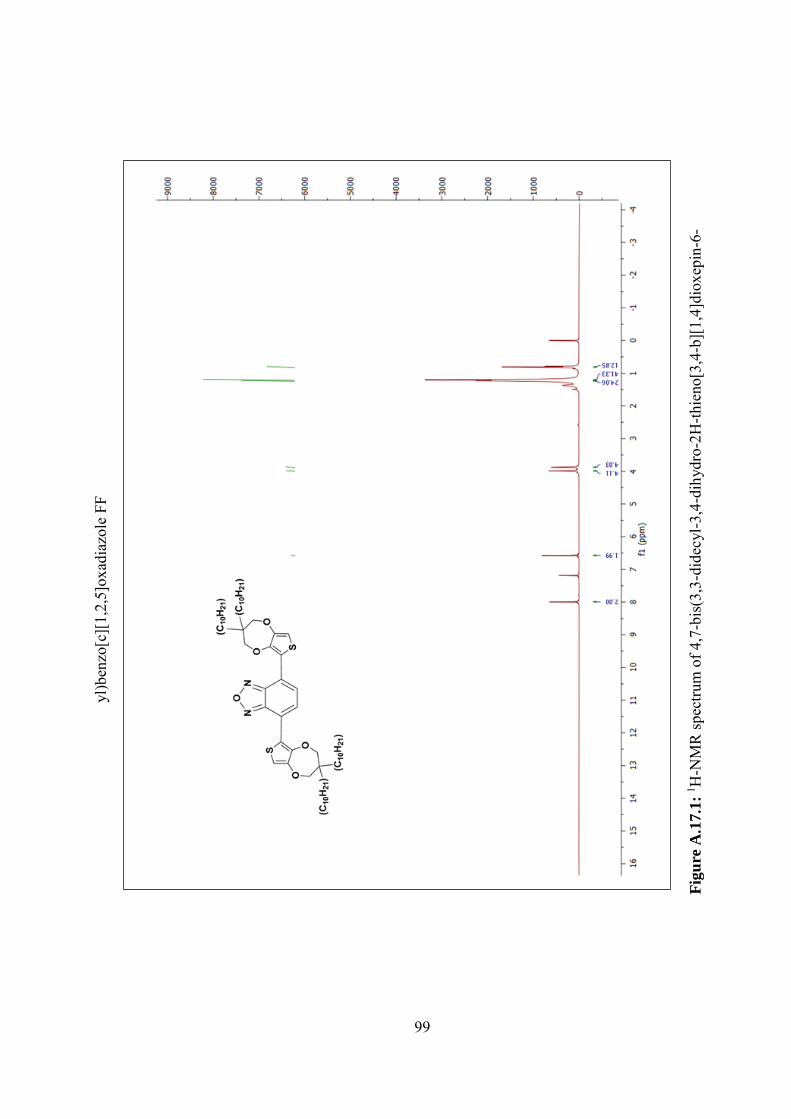
99
Fig
ure
A.1
7.1
: 1 H-N
MR
spec
trum
of 4
,7-b
is(3
,3-d
idec
yl-3
,4-d
ihyd
ro-2
H-th
ieno
[3,4
-b][
1,4]
diox
epin
-6-
yl)b
enzo
[c][
1,2,
5]ox
adia
zole
FF