II
V •Contract N00014-76-C-0495
"LE
FUNDAMENTAL INVESTIGATION OF PITTING CORROSIONIN STRUCTURAL METALS
THEODORE R. BECK -Ton-
ELECTROCHEMICAL TECHNOLOGY CORP. ELECTE3935.LEARY WAY NW, AUG 0 3 1981SEATTLE, WA 981.07(206) 632-5965
FINAL REPORT FOR PERIOD JULY 1975-.JUNE 1981
SReproduction in whole or in part is permitted forany purpose of the United States Gowernment.Distribution is unlimited.
Prepared for
OFFICE OF NAVAL RESEARCH"i ~800 North Quincy Street
Arlington, VA 22217
July 1981
4I i
,+ ,.+ + : ;, , .-

Unclamns fflfISCCURI?' CLSS-OMATIIOI 0V T64119 MAS i'111%be f... lenfoed)__________________
REPORT DOCUMENTATION PAGE REA'D INSTRUCTIONS_________________________BEFO.RE COMPLETING FORM
V*PI1101111OTft.hDR - -Gj OVT ACCVW1B N. I fI~CATA;.OG NUMBER
4 YuTLC (and Subtitle) S. Is, "441" p 0 _______
undamental Investigation of Pitting Corrosion ia'erit, Structural Metals~ .ujM5 Ju w81
7. AUm~ll~o)S. COWI RAC? 0i GRANT wuUMIER(s)
(J Theodore R./ Beck \/, N0014-76-C4.495 L
S. PaPIORMING ORGANIZA7104 NAMC AN* ADOONES to. ipop"GA V~LET POET TASi
SeattleA WA 810
11. COT ROLLING OPFFICC NAME AND ADDRESS ( aUJ...7 0ATE
13- 4'4J0UE(nit PAGES
14 MO*41'oftiNG AG3FhiCV sAME A AD0RfSS'uf dilff~eqnt iroom Controlli~ng Office.) IS. S9ILJ6411'Y CLASS. (of this report)
Office of Naval ResearchMaterials Science Division UnclassifiedArlington, VA 22217 I CCL. SIRICATIO4 DOWNGRADING
I$ OlSRIfIUTION STATIEME14T (of this Report)
17. DuSTRuGUTION STATEMENT (of the obstroct menterd in Black 20, it different fros Report)
Reproduction in whole or part is permitted for any purpose of the UnitedStates Government. Distribution is unlimited.
18. SU)PPLEMENTARY NOTES
IS. KEY WORDS (Con~tinue an, revarse aide It necessary and identify by block fsnumber)
Corrosion, pitting, iron, aluminum, magnesium, titanium, stainless steel,mass transport, salt film.
0. SSTRAC? I'Cmnlnd,. an' r.eversde of^I neeeeenV and 1410,111111 by block wink.,)
iis report gives a sumary of the main electrochemical features of pittingcorrosion of iron, aluminuA', magnesium, titanium, and stainless steel inhalide solutions. Ohmic and mass transport limited corrosion regions andeffect of hydrodynamic flow are described. Barrier films of metal halide
s alt are formed on the metal surface for these metals in the mass transportlimited region. The electrical properties of thes* salt films were determined.A mechanism is proposed for the protection from pitting of stainless steelsbflowini seawater.
00I AM7 173 ZITOW OV1 ISSLEgUnclassifiedV
SE9CURITY CLASSIFICATIONM O' THIS VAGC ,Wo Daer Etrod)
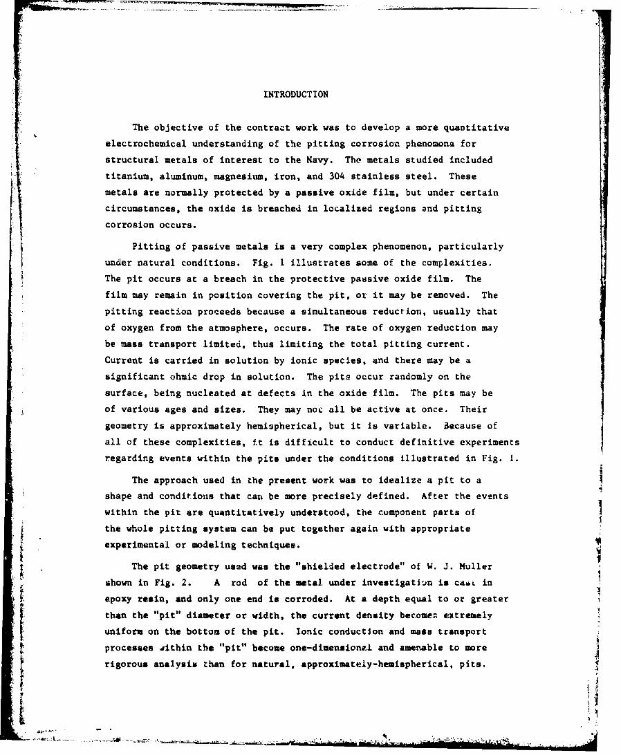
INTRODUCT ION
The objective of the contract work was to develop a more quantitative
electrochemical understanding of the pitting corrosion phenomona for
structural metals of interest to the Navy. The metals studied included
* titanium, aluminum, magnesium, iron, and 304 stainless steel. Thesemetals are normally protected by a passive oxide film, but under certain
circumstances, the oxide is breached in localized regions and pitting
corrosion occurs.
Pitting of passive metals is a very complex phenomenon, particularly
under natural conditions. Fig. 1 illustrates some of the complexities.
The pit occurs at a breach in the protective passive oxide film. The
film may remain in position covering the pit. or it may be removed. The
pitting reaction proceeds because a simultaneous reduction, usually that
of oxygen from the atmosphere, occurs. The rate of oxygen reduction may
be mass transport limited, thus limiting the total pitting current.
Current is carried in solution by ionic species, and there may be a
significant ohmic drop in solution. The pits occur randomly on the
surface, being nucleated at defects in the oxide film. The pits may be
of various ages and sizes. They may noc all be active at once. Their
geometry is approximately hemispherical, but it is variable. Because of
all of these complexities, it is difficult to conduct definitive experiments
regarding events within the pits under the conditions illustrated in Fig. 1.
The approach used in the present work was to idealize a pit to a
shape and conditions that cans be more precisely defined. After the eventswithin the pit are quantitatively understood, the component parts of
the whole pitting system can be put together again with appropriate
experimental or modeling techniques.
t The pit geometry used was the "shielded electrode" of W. J. Muller
shown in Fig.. 2. A rod of the metal. under investigati -in is caiL in
epoxy resin, and only one end is corroded. At a depth equal to or greater
than the "pit" diameter or width, the current density becomen ex~tremely
uniform on the bottom of the pit. Ionic conduction and mass transport
t processes #ithin the "pit" become one-dimensionalI and amenable to more
rigorous analysis than for natural, approximately-hemispherical, pits.

Accession ForNTI SGRAEIiS•: 2
2 DTIC TABUninnouncedJustification
By-Distribution/
Availability CodesAvail and/or
Solution Dit peci al
02 B j
+ h02 \+ 2 0 + 2e- 2OH"
Passive
Oxide
Layer •
lvpi ge-
I a
Metal
I
Fig. 1. Pit In passive metal driven by ozynen reduction onadjacent passive surfaceI 'I!
I
-:!

3
Solution Transport Processes 3
H 20 X- i H÷ M2_ O .2
PorousLayer 1
Layer
Rsactiors at I
4+2M---- M •+ 2a
H+H 2 0- M + 2NH + 2e
2e + 2e - H2
Reactions In 2 and 3
M(X2 == ti' + 2X".
+ HO-- M + 2e
Fig. 2. One,..laensional pit, reactions and transportprocesses (divalemt netal Ion used for Illustration).
.1
•• , -!
4
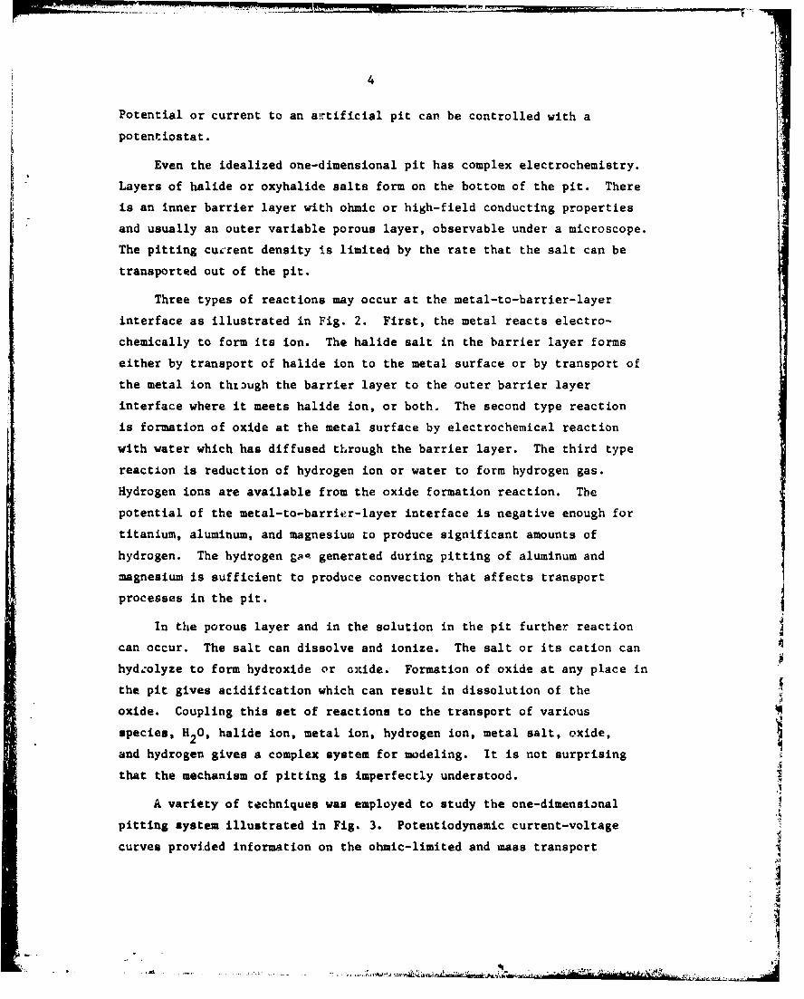
Potential or current to an artificial pit can be controlled with a
potentiostat.
Even the idealized one-dimensional pit has complex electrochemistry.
Layers of halide or oxyhalide salts form on the bottom of the pit. There
is an inner barrier layer with ohmic or high-field conducting properties
and usually an outer variable porous layer, observable under a microscope.
The pitting cuerent density is limited by the rate that the salt can be
transported out of the pit.
Three types of reactions may occur at the metal-to-barrier-layer
interface as illustrated in Fig. 2. First, the metal reacts electro-
chemically to form its ion. The halide salt in the barrier layer forms
either by transport of halide ion to the metal surface or by transport of
the metal ion thzIugh the barrier layer to the outer barrier layer
interface where it meets halide ion, or both. The second type reaction
is formation of oxide at the metal surface by electrochemical reaction
with water which has diffused through the barrier layer. The third type
reaction is reduction of hydrogen ion or water to form hydrogen gas.
Hydrogen ions are available from the oxide formation reaction. The
potential of the metal-to-barrier-layer interface is negative enough for
titanium, aluminum, and magnesium to produce significant amounts of
hydrogen. The hydrogen SgR generated during pitting of aluminum and
magnesium is sufficient to produce convection that affects transport
processes in the pit.
In the porous layer and in the solution in the pit further reaction
can occur. The salt can dissolve and ionize. The salt or its cation can
hydzolyze to form hydroxide or oxide. Formation of oxide at any place in
the pit gives acidification which can result in dissolution of the
oxide. Coupling this set of reactions to the transport of various
species, H2 0, halide ion, metal ion, hydrogen ion, metal salt, oxide,
and hydrogen gives a complex system for modeling. It is not surprising
that the mechanism of pitting is imperfectly understood.
A variety of techniques was employed to study the one-dimensional
pitting system illustrated in Fig. 3. Potentiodynamic current-voltage
curves provided information on the ohmic-limited and mass transport
A

411
LaJ r_ I0
Ciei
0 u
LU ~ 0
60
o go

6
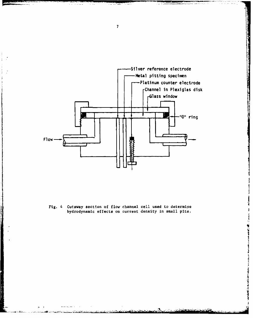
limited regimes. Electrolyte flow past the mouth of the pits with the
flow cell illustrated in Fig. 4 gave quantitative mass transport data.
Potentiostatic current-time data under stagnant electrolyte conditions
gave further quantitative correlations of unsteady-state mass transport.
On a shorter time scale, current transients from step potential experiments
provided information on the electrical properties of the barrier salt
film. Open-circuit potential decay experiments provided further data on
salt-film electrical properties. Volumetric rates of hydrogen
evolution were also measured, as well as apparent valence of metal
dissolution. In order to study individual small pits in stainless steel,
the artificial pit illustrated in Fig. 5 was used.
SUMMARY
A brief summary of the results for the various metals is presented
here. More detailed data are given in the papers published and in
progress.
Potentiodynamic Curves, Effect of Hydrodynamic Velocity
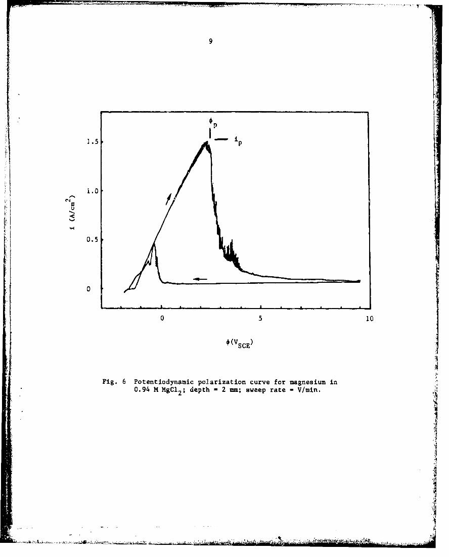
A typical potentiodynamic curve is shown in Fig. 6 (Tech. Rept. 5).
This curve is for magnesium, but similar shapes are found for other metals.
In the ascending, approximately-linear region up to ý p i the current
density is limited by the ohmic resistance in solution between the working 4
electrode surface and the reference electrode. Iron has an etched surface
in this region, whereas titanium, aluminum, and magnesium develop
microtunneling. At the peak, p, ip, salt precipitation occurs and the
current density decreases to a low value, determined by the mass transport
rate of the corroding metal ion out of the pit. In this region, the
metal surface is electropolished. On the negative potential sweep, the
current density remains at the mass transport limited rate to a lower
potential because there is less agitation by coevolved hydrogen bubbles.
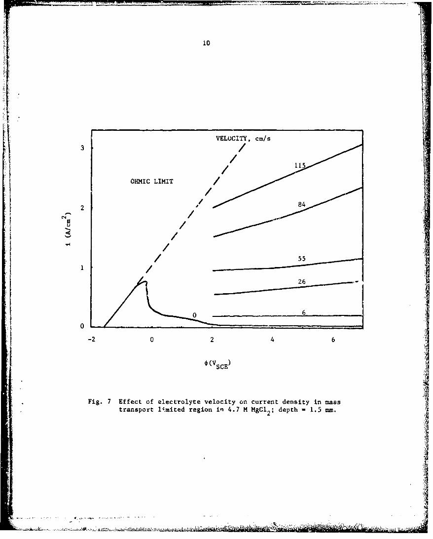
The effect of electrolyte velocity past the mouth of the pit in the flow
cell is shown in Fig. 7. Results for iron are given in Technical Report No. 1.
)
7
- Slver reference electrode
Metal pitting specimenPlatinum counter electrode
-Channel in Plexiglas disk
lass window
Ha._1"0" ring
Flow-ý
Fig. 4 Cutaway sect$.on of flow channel cell used to determinehydrodynamic effects on current density in small pits.
~1
I.
*1
4

8
Solution
Metal
Fig. 5 Single artificial pit in hole in lacquer layershoving approximate corrosion profiles. (Diameterof pit approximately 3.0070 cm.)
9
1 .5 p _
S 0
0.5
0
0 5 1
* (Vs
Fig. 6 Potentiodynamic polarization curve for magnesium in0.94 M MgC1 2 ; depth -2 mm; sweep rate -V/mmn.
"' -. .R1t .. .11I"R.,W1
10 "
VELOCITY, cm/s
3//
OHMIC LIMIT
2 842/
U /"" /• /
0 60
-2 0 2 4 6
*(VSCE)
Fig. 7 Effect of electrolyte velocity on current density in masstransport 1imited region in 4.7 M MgC1 2; depth - 1.5 mm.
11
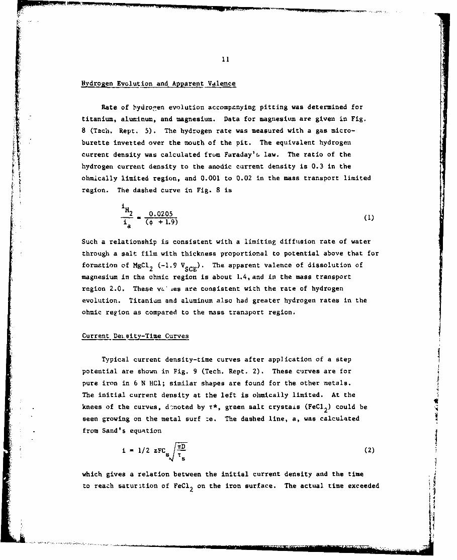
Hydrogen Evolution and Apparent Valence
Rate of hydronen evolution accompanying pitting was determined for
titanium, aluminum, and magnesium. Data for magnesitum are given in Fig.
8 (Tach. Rept. 5). The hydrogen rate was measured with a gas micro-
burette inverted over the mouth of the pit. The equivalent hydrogen
current density was calculated frum Faraday'I law. The ratio of the
hydrogen current density to the anodic current density is 0.3 in the
ohmically limited region, and 0.001 to 0.02 in the mass transport limited
region. The dashed curve in Fig. 8 is
iH2 0.0205
( + 1.9)a
Such a relationship is consistent with a limiting diffusion rate of water
through a salt film with thickness proportional to potential above that for
formation of MgC1 2 (-1.9 V SCE). The apparent valence of dissolution of
magnesium in the ohmic region is about 1.4, and in the mass transport
region 2.0. These v'i es are consistent with the rate of hydrogen
evolution. Titanium and aluminum also had greater hydrogen rates in the
ohmic region as compared to the mass transport region.
Current Detsity-Time Curves
Typical current density-time curves after application of a step
potential are shown in Fig. 9 (Tech. Rept. 2). These curves are for
pure iron in 6 N HCl; similar shapes are found for the other metals.
The initial current density at the left is ohmically limited. At the
knees of the curves, d&-noted by T*, green salt crystais (FeCl 2 ) could be
seen growing on the metal surf ze. The dashed line, a, was calculated
from Sand's equation
i 1/2 zFC (2)
which gives a relation between the initial current density and the time
to reach saturition of FeCl 2 on the iron surface. The actual time exceeded•. I•
,I
-5~
12
0OHMICLIMITED REGION
1
00%
-A
2 MASS TRANSPORT"- :LIMITED REGION
- -
o 5 10 15 20
*(Vace)
Fig. 8 Ratio of hydrogen current density to anodiccurreut density in ohmic limited and masstrausport limited rcgions for 0.94 M MgCl2.*
- -. -. V *

13
p
I C0
I heI -4
I QJ/ he �
I4.I 0
.0-44. cJ
4.I
0*I
4. -4I
4. *1'4&JLJC.
- w �.
U0
4. 4-'_
W .4
JJCAMhe .0
C.,0 �hia. C
C- Wa�j -
-4.CACGJCUheW4.1o
w
4.1..
I.d�he
a.-
0 0.- SClJ00
-4
i
I
'1
k�- -� - -�-.,-,�ra-'- �..�---.-- -.--.-- -

14
this value, indicating supersaturation. The overshoot in current density
decay is due to the precipitated salt layer. At the minimum in the current,
the precipitated salt crystals dissolved and a transparent salt layer
remained. The final d-cay in current density can be attributed to growth
of the diffusion layer thickness to fill the pit. The diffusion limiting
current density can be described by
rj iL - z FC 4 (3)
Eq. 3 is plotted as line c in Fig. 9. The actual data are higher than
line c, probably due to contribution by electrolytic migration of Fe.3
At a time of about 10 a, the current density becomes constant for steady
state diffusion out of a 0.1 cm deep pit.
Fasnt Electrical Transients
Rapid transient response of current density to step changes in
potential under mass transport limiting conditions can be used to
determine the barrier salt film properties. At the mass transport limit,
most of the potential trop in the pit is across the salt film. The
initial peak current densities arr a function of the initial potential,
which determines the initial thickness, t1 Ohmic and high-field
conduction give the following equations respectively.
i K(P - e +*)(4)
and
i exp (5)
It turns out that magnesium and titanium halides have high field conduction,
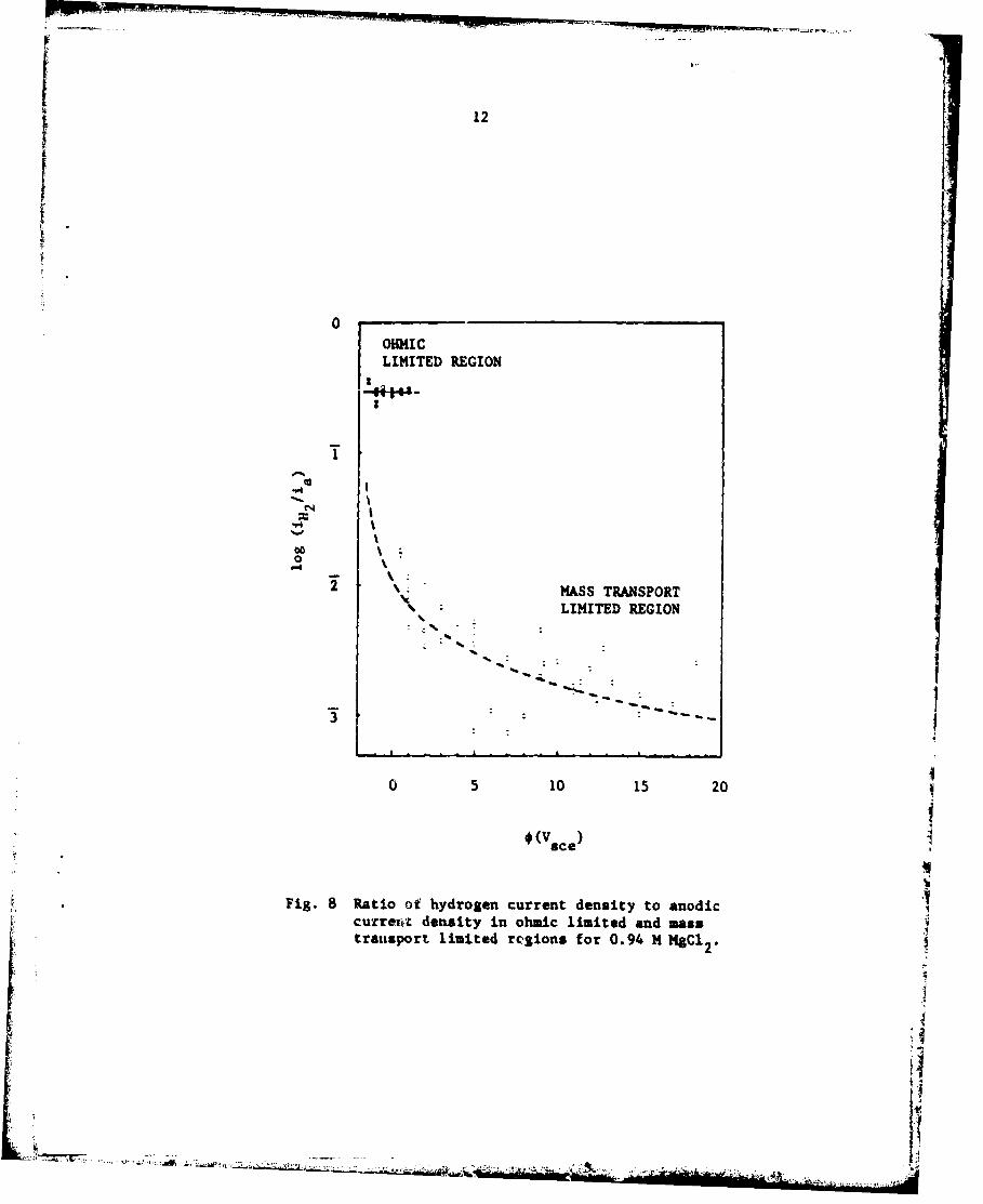
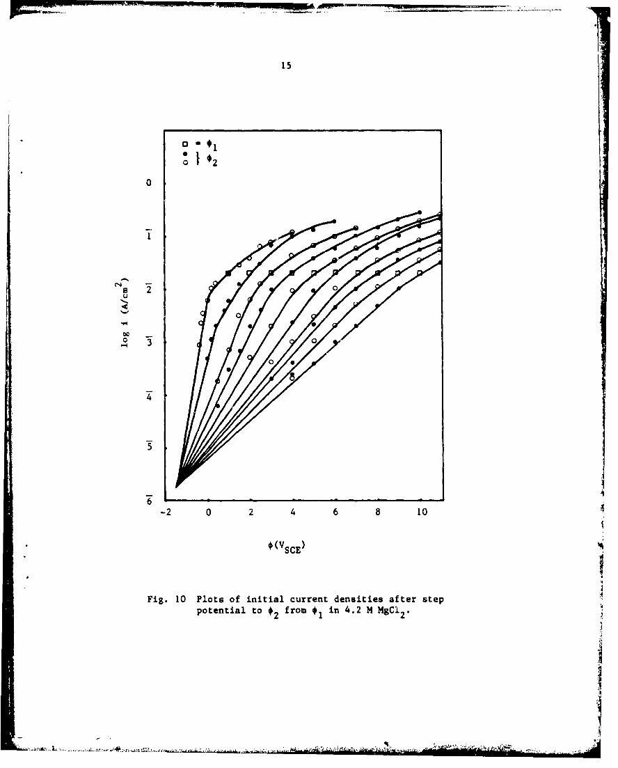
and iron and aluminum halides are ohmic. Data for magnesium are shown in
Fig. 10 (Tech. Rept. 5). Values of t /0 are found to be linear with
potential in agreement with the barrier layer thickness being proportional
to potential and a constant value of 8. At high current densities, there
appears to be an additional series ohmic resistance. Experimental results
15
0
0
C .)0
-2 0 2 4 6 8 10
• * (VscE)
0 044
I
Fig. 10 Plots of initial current densities after step
potential to *2 from *I in 4.2 M MgCi 2 .to 2
AI!-nr L..- .~. . ,~.7'D Q~t># -i.,

16
indicate that this ohmic resistance may be due to the outer porous salt
layer.
Open-circuit potential transients were also used to determine the
barrier film properties and gave consistant results to the step potential
experiments.
Velocity Effects with Stainless Steel
It has long been known that stainless steels are subject to pitting
attack in stagnant seawater, and seawater velocities greater than 5 ft/s
are recommended to avoid pitting. The mechanism of protection by flowing
seawater was not previouly established, however. Results from the
present work of flow experiments with small pits and analysis of effects
of the hydrodynamic conditions on mass transport of corrosion products
showed that flow of 5 ft/s limits pits to micrometer size. Even though
pits may nucleate, they are extinguished by fluid flow when they reach
a certain size.
The relation of critical velocity for extinguishing corrosion versus
pit radius is shown in Fig. 11(Tech. Rept. 3). Two curves are showr in
Fig. 11, one for I N NaCl used in the experiments, and one calculated for
seawater (0.6 N NaCl). Pitting is allowed at velocities below the curves
and not allowed above the curves. For example, for a velocity of 5 ft/s
(152 cm/s), the maximum pit radius allowed is about 2 Um, invisible to
the naked eye.
Many experiments were conducted to test the relationship in Fig. 11.
Pits established on a flat surface of 304 stainless steel under stagnant
conditions and allowed to grow to a size visible under a binocular
microscope at 60X were completely extinguished by subsequent flow of
electrolyte. The experiments were not as quantitative as desired though,
because a distribution of pit sizes was obtained. Two methods were used
to obtain single pits of controlled size. One was to coat a stainless
steel specimen with a lacquer and punch a hole in the lacquer with a pin
(Fig. 5). The other method was to make an artificial pit by corroding the
ends of various-diameter stainless steel dires embedded in epo-Ay resin
=,,

17
i
100
103 pittingnot&Illowed 10
152 cm/s100"1 I°°1 1
10
__ 0.1 q
1 N NaCIpittingallowed 0.01
10"1 $seawater0.001
ioSlo-~102 1,_ _.• _S10-5 10.4 10-3 10"2 10-I 1
r (cm)
Fit. 11 Critical velocity for pitting of passivating metal as a functionof pit radius.
I

18
(Fig. 3). In both of these cases of artificial pits, flow caused the
pitting current to decrease at the appropriate velocity according to
Fig. 11; but the current did not go to zero. It was found that crevice
corrosion continued between the stainless steel and the lacquer or the
N epoxy resin.
Formation of Salt Films in Small Pits
A mass transport analysis of small pits showed that at moderate
salt concentrations, such as in seawater, the initial corrosion current
densities may be very large and a salt of the corroding metal is likely
to form on the metal surface (Tech. Rept. 4). Observations of pitting
under a microscope indicated that a salt film was present in the pits in
stainless steel.
INDEX OF TECHNICAL REPORTS (submitted with DD 1473)
1. Effects Nf Hydrodynamics on Pitting, April, 1977 (Publication No. 1).
2. Formation of Salt Films During Passivat'on of Iron, December, 1978(Publication No. 6).
3. Experimental Observatiors and Analysis of Hydrodynamic Effects onGrowth of Small Pits, June, 1979 (Publication No. 4).
4. Occurance of Salt Filmi• During Initiation and Growth of CorrosionPits, March, 1980 (Publication No. 3).
5. Corrosion of Magnesium at High Anodic Potentials, July, 1981(Publication No. 5).
INDEX OF PUBLICATIONS
1. T. R. Beck, "Effect of Hydrodynamics on Pitting", Ccorrosion, 33,9 (1977).
2. R. Alkire, P'. Ernuberger, and T. R. Beck, "Oczurrence of Salt FilmsDuring Repassivation of Newly Generated Metal Suifaces", J.Electrochem. Soc., 125, 1382 (1978).
3. T. R. Beck and R. D. Alkire, "Occurrence of Salt Films DuringInitiation and Growth of Corrosion Pits", J. Electrochem. Soc.,126, 1662 (1979).
4. T. R. Beck and S. G. Chan, "Experimental Observations and Analysisof Hydrodynamic Effects on Growth of Small Pits", Corrosion,(accepted for publication).
5. T. R. Beck and S. G. Chan, "Corrosion of Mp.gnesium at High AnodicPotentials", to be submitted to .1. Electrochem. Soc.; abbreviatedversion submitted to H. H. Uhlig 75th Birthday Symposium Volume,The Electrochemical Society, Fall Meeting, 1981.
6. T. R. Beck, Formation of Salt Films During Passivation of Iron", tobe submitted to J. Electrochem. Soc.
7. T. R. Beck and S. G. Chan, "Corrosion of Aluminum at High AnodePotentials", to be submitted to J. Electrochem. Soc.
8. T. R. Beck, "Pitting of Titanium, III Electrical Properties ofSalt Film", to be submitted to J. Electrocher. Soc.
i'I

20
EXTENDED ABSTRAC £S
1. R. C. Alkire, D. W. Ernsberger and T. R. Beck, The Occurence ofSalt Films During the Initial Stages of Corrosion, Ext. Abs. No. 93,The Electrochemical Society, Fall Meeting, Las Vegas, NV, October17-22, 1976.
2. T. R. Beck, Pitting of Titanium, III Electrical Properties of SaltFilm, Ext. Abs. No. 64, The Electrochemical Society, Spring Meeting,Seattle, WA, May 21-26, 1978.
3. T. R. Beck, Formation of Salt Films During the Passivation of Iron,Ext. Abs. No. 128, The Electrochemical Society, Fall Meeting,Pittsburgh, PA, October 15-20, 1978.
4. T. R. Beck and S. G. Char, Jxperimental Observation and Analysis ofHydrodynamic Effects on Growth of Small Pits, Ext. Abs. No. 239,The Electrochemical Society', Fall Meeting, Los Angeles, CA, October14-19, 1979.
5. T. R. Beck, Corrosion of Aluminum and Magnesium in some OrganicSolvents, Ext. Abs. No. 159, The Electrochemical Society, FallMeeting, Hollywood, FL, October 5-10, 1980.
6. T. R. Beck and S. G. Chan, Corrosion of Magnesium at High AnodicPotentials, Ext. Abs. No. , The Electrochemical Society, FallMeeting, Denver, CO, October 11-16, 1981.
I
i
,i
S,~~~~~ : C.. . . . . ..... ...... ' ....... - ,.J- -, 2• .•"•...... •••••• -•,.••••,,, "'