MassachusettsInstitute of Technology
Artificial IntelligenceLaboratoryMemo No, ~94 November1976
LOCAL METHODS FOR LOCALIZING FAULTS
IN ELECTRONIC CIRCUITS
byJohande Kleer
Abstract:Thework describedin this paperis partof an investigationof the issues
Involved in makingexpertproblemsolving programsfor engineeringdesignand formaintenanceof engineeredsystems. In particular, the paper focuses on thetroubleshootingof electronic circuits. Only the individual propertiesof thecomponentsare used,and not thecollectivepropertiesof groupsof components.Theconceptof propagationis introduced which uses the voltage-currentpropertiesofcomponentsto determineadditional information from given measurements.Twopropagatedvaluescan be discoveredfor thesamepoint. This is calleda coincidence.In a faulted circuit, the assumptionsmadeaboutcomponentsin the coincidingpropagationscanthen be usedto determineinformation aboutthefaultinessof thesecomponents.In order for the programto dealwith actualcircuits, It handleserrorsin measurementreadingsand tolerancesin componentparameters.This is donebypropagatingrangesof numbersinsteadof single numbers. Unfortunately, thecomparingof’ rangesIntroducesmany complexitiesInto the theory of coincidences.In conclusion,we show how such local deductionscan be usedasthe basis forqualitativereasoningand troubleshooting.
Work reportedhereinwas conductedin partat the Artificial IntelligenceLaboratoryat the MassachusettsInstituteof Technologyandthe Intelligent InstructionalSystemsGroupat Bolt Beranekand Newman. The Artificial IntelligenceLaboratory issupportedin part by the AdvancedResearchProjectsAgency of the DepartmentofDefenseand monitored by the Office of Naval Researchunder Contract NumberNOOOI4-75-C-O64~.The Intelligent InstructionalSystemsGroup is supportedin partundercontractnumberMDA 9O~-76-C-OlO8jointly sponsoredby AdvancedResearchProjectsAgency, Air ForceHuman ResourcesLaboratory,Army ResearchInstitute,and Naval PersonnelResearch& DevelopmentCenter.
2
INTRODUCTION
Troubleshootinginvolvesdeterminingwhy a particularcorrectly designedpieceof equipment
Is not functioning asIt was intended; the explanationfor the faulty behaviorbeing that the
particular piece of equipmentunderconsiderationIs at varianceIn someway with Its design. To
troubleshoot,a sequenceof measurementsmust be madeto localize this point of variance,or fault.
The problem for the troubleshooterIs to determinewhat a particular measurementtells him and
what measurementto makenext.
This paperInvestigateshow local knowledgeaboutthe circuit can be usedto answerthese
two questions. By local, we mean that only one particular componentIn the circuit will be
consideredat one tIme and any interactionsbetweenlargercollectionsof componentswill be
Ignored. The teleology of collectionsof more than one componentwill not be discussed;instead
only the characteristicsof the individual componentswill be used(suchastheir VIC’s -- the
voltage-currentcharacteristics).
The central goal of’ this researchIs to achievea better understandingof troubleshooting.
One role for this new knowledgeis in an expertproblemsolving program. However,it can alsobe
used In the expert componentof an ICAI tutoring system. <Brown et.al., 74> This meansthat there
has to be some communication between the troubleshooting strategy and the human student. In
fact, this is also true if we wantedthe expertproblemsolver to explain its deductions. Therefore
we haveimposedthe constraintthat our troubleshooter’sdeductionsbe explainable.This constraint
hasmotivated many of the designchoicesin the Implementationof this theoryasa program
(INTER). In this paperwe also include somecommentsabouthow the theory can be used In a
tutoring context.
The way to obtain new information about the circuit is to makea measurement.In
troubleshooting,new Information Is provided by coincidences. In the most generalsensea
coincidenceoccurswhena valueat oneparticularpointIn thecircuit canbe deducedin a numberof
different ways. Such a coincidenceprovidesinformationabout the assumptionsmadein the
deductions. A coincidencecan occurIn many different ways; it can be the differencebetweenan
expectedvalue and a measuredvalue (e.g. expectedoutput voltage of the power supply and the
actual measuredvalue); it can be the differencebetweena value predicted by Ohm’s law and a
measuredvalue; or It can be thedifferencebetweenan expectedvalue and the valuepredictedby
thecircuit designer. TherearenumerousotherpossibilIties.
A troubleshootinginvestigation into a particular circuit proceedsin two phases. The first
involves discoveringmore valuessuch as currentsand voltagesoccurring at variouspoints in the
circuit, and the secondinvolvesfinding coincidences.Theusefulnessof coincidencesis basedon the
fact that nothingcan be discoveredaboutthecorrectnessof the circuit wIth a measurementunless
something is known about the value at that point of the circuit in the first place. If nothing Is
known aboutthat point, a measurementwill say nothing aboutthe correctnessof the components.
One actual measurementimplies many other values in the circuit. The first phase of the
investigationinvolvesdiscoveringmany suchvalues In thecircuit, and the secondinvolvesmaking
measurementsat thosepointsfor which we know theImplied valuesso that we can seewhether the
circuit Is acting asit should,or if somethingIs wrong.
We will call suchan implication a propagattonand the discovery of a value a point at which
we already know a propagatedvalue for a coincidence. When these two values are equal, we will
call sucha coincidencea corroboration and when they aredifferent we will call it a contradiction.
Information about the faultinessof componentsin the circuit can only be gained through
coincidences. Propagationsinvolve making certain assumptionsabout the circuit and then
predictingvaluesat other points from these. Theseassumptions can be of many kinds. Some of
them involve Justassumingthecomponentitself is working correctly. For example, we can derive
the currentthrougha resistor from thevoltageacrossit. Others require knowing something about
how the circuit should work, thus predicting what values should be. For example,knowing the
transistoris acting asa classA amplifier,we can assumeIt is alwaysforward-biased. Coincidences
between propagatedvaluesand new measurementsprovides information about the assumptions
madein the propagation~
Coincidencesbetweenpropagatedvalues and values derived from knowing how the circuit
should work requirea teleologicaldescriptionof the circuit. As indicatedearlier, this paper doesnot
4
investigatetheselatter kinds of assumptions.Researchinto this areawas pursuedby Brown
<Brown,74> <Brown, 76>. Instead,this paperinvestigatespropagationsemploying only assumptions
about the componentsthemselves. Although, at first sight, the teleological analysisof
troubleshootingIs the more interestIng, ft cannotproceed without being able to propagate
measurementsin the circuit.
It may appearthat this kind of circuit reasoningis essentiallytrivial and thus should not be
investigated. This paper will show that the issuesof local nonteleologicalreasoningare, in fact,
very difficult. Someof the problemsarisebecausethe nonteleologicalknowledgeshould interact
with the teleologicalknowledge. A particularly difficult problemwhich will ariseagainand again
is the questionof’ how far to propagatevalues. Often the propagationswill be absurd,and only a
small amount of’ teleologicalknowledgewould have pruned out theseuninterestingpropagations.
Part of the effort of this paper is directedinto determiningwhat other kinds of knowledgeand
interactionis required,asidefrom thenonteleological,in order to troubleshootcircuits effectively.
The sectionsthat follow presentan evolution of the knowledgerequired. The first sections
will presenta simple theory aboutlocal reasoningand troubleshooting. Next the problemsof the
approach will be investigated,and someof themansweredby a more sophisticatedtheory. Finally
the deficienciesof the theory and how It must interact with more teleologicalknowledgewill be
discussed.
SIMPLE LOCAL ANALYSIS
The domain of electronicsunderconsiderationwill be restricted to DC circuits. These are
circuits consistingof resistors,diodes,zenerdiodes,capacitors,transistors,switches,potentiometers
and DC voltage sources. All AC effects will be ignored although an analogoustype of analysis
would work for AC circuits. It will be assumedthat the topology of thecircuit doesnot changeso
that wiring errorsor accidentalshortswill not be consideredas possiblefaults.
In this sectionwe will presenta simple theory of propagation. Initially, only numeric values
will be propagated.Interactinglocal expertsproducethe local analysis. Each kind of component
hasa special expert which, from given input conditions on its terminals,computesvoltagesand
5
currentson other terminals. For example,the expert for a transistor might, when it seesa base-
emittervoltageof less than .55 volts, infer a zerocurrentthrough the collector.
This propagationscheme is very similar to that used in EL <Sussman & Stallman, 75>
<Stallman& Sussman,76>. Although similar in that they are both based on propagation of
constraints, the different goals of analysis and troubleshooting lead to many differences in the
details of the two propagation schemes. Therefore, we include a very terse description of our
propagation scheme,and the reader is referred to the two EL papers for a deeper explanation of
propagation of constraints.
SinceEL is prImarily interested in analysis,It must discover every value in the circuit. When
conventional numeric propagation fails It resorts to propagating variables and solving algebraic
equations. Since we are mainly Interested In explaining and not analysis the propagation of
variables and solving of equations is not done.
In order to give explanations for deductions, a record Is kept as to which expert made the
particular deduction. Most propagations make assumptions about the components Involved in
making It, and theseare stored on a list along with the propagated value. Propagations are
represented as:
(<type> <location> (<local—expert> <component> <arg>) <assumption—list>)
<type> is VOLTAGE or CURRENT.
<location> is a pair of nodesfor a voltage and a terminal for a current.
Note that every such propagation has a value associatedwith it. For those examples where the
exact numerical value is important, exact numbers will be included.
The simplest kinds of propagations require no assumptionsat all. These are the Kirchoff
voltageand current laws.
6
Ni
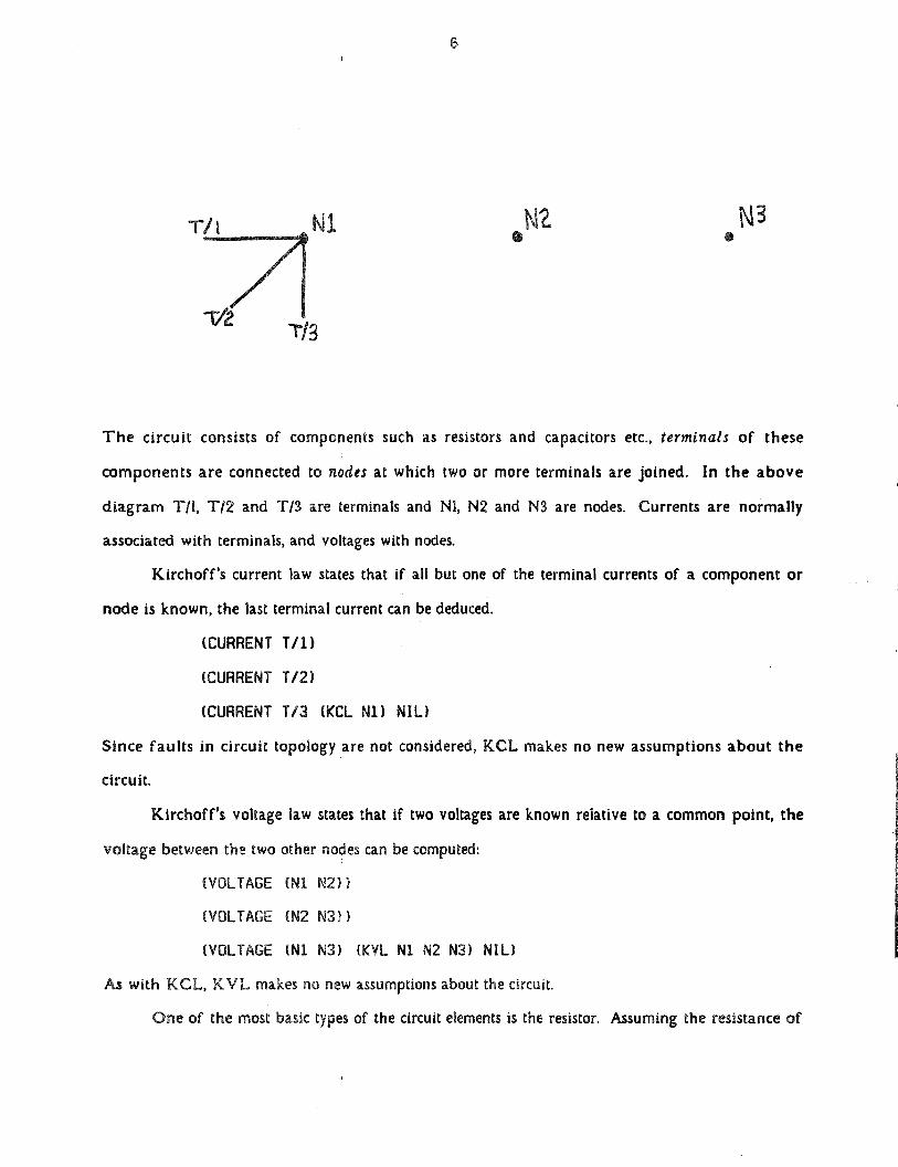
The circuit consists of components such as resistors and capacitors etc., termtnais of these
componentsare connectedto nodes at which two or more terminals are Joined. In the above
diagram T/l, TI 2 and T/~are terminals and NI, N2 and NS are nodes. Currents are normally
associatedwith terminals, and voltageswith nodes.
Kirchoff’s current law states that if all but one of the terminal currents of a component or
node is known, the last terminal current can be deduced.
(CURRENT 1/i)
(CURRENT 1/2)
(CURRENT 1/3 (KCL Ni) NIL)
Since faults in circuit topology are not considered,KCL makes no new assumptionsabout the
circuit.
Kirchoff’s voltage law statesthat if two voltagesare known relative to a common point, the
voltagebetweenthetwo othernodescan becomputed:
(VOLTAGE (Ni N2))
(VOLTAGE (N2 N3))
(VOLTAGE (Ni N3) (KYL Ni N2 N3) NIL)
As with KCL, KVL makesno new assumptionsaboutthecircuit.
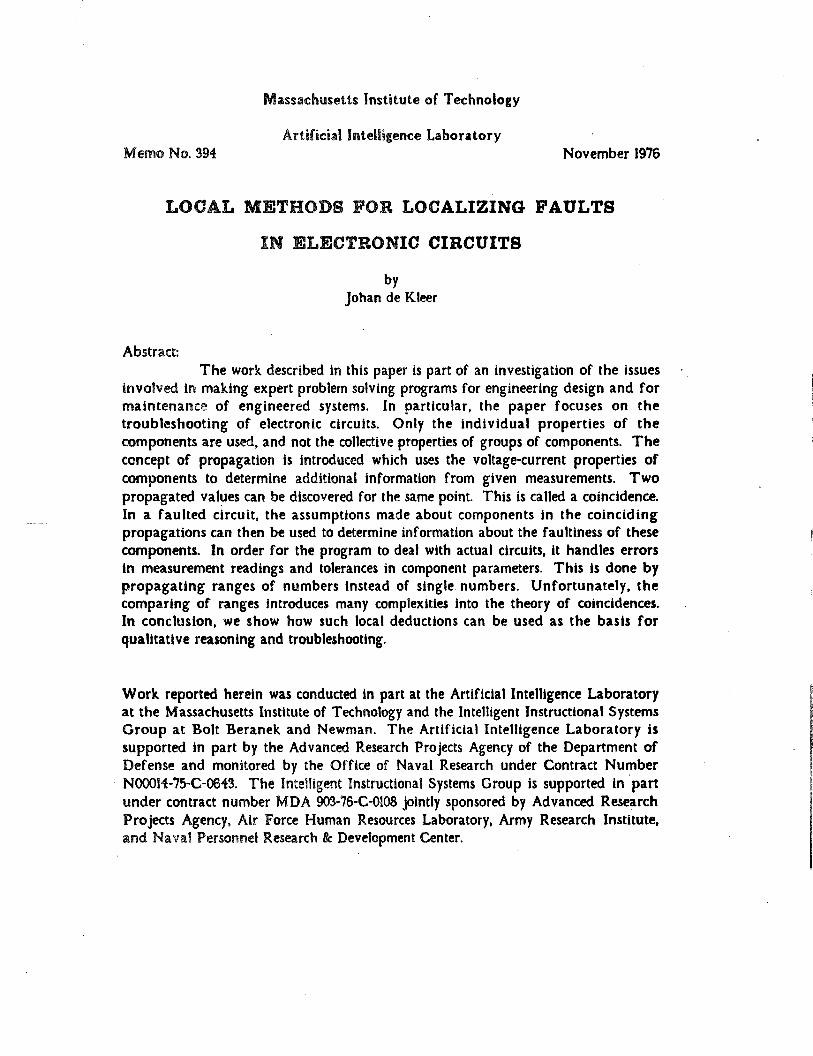
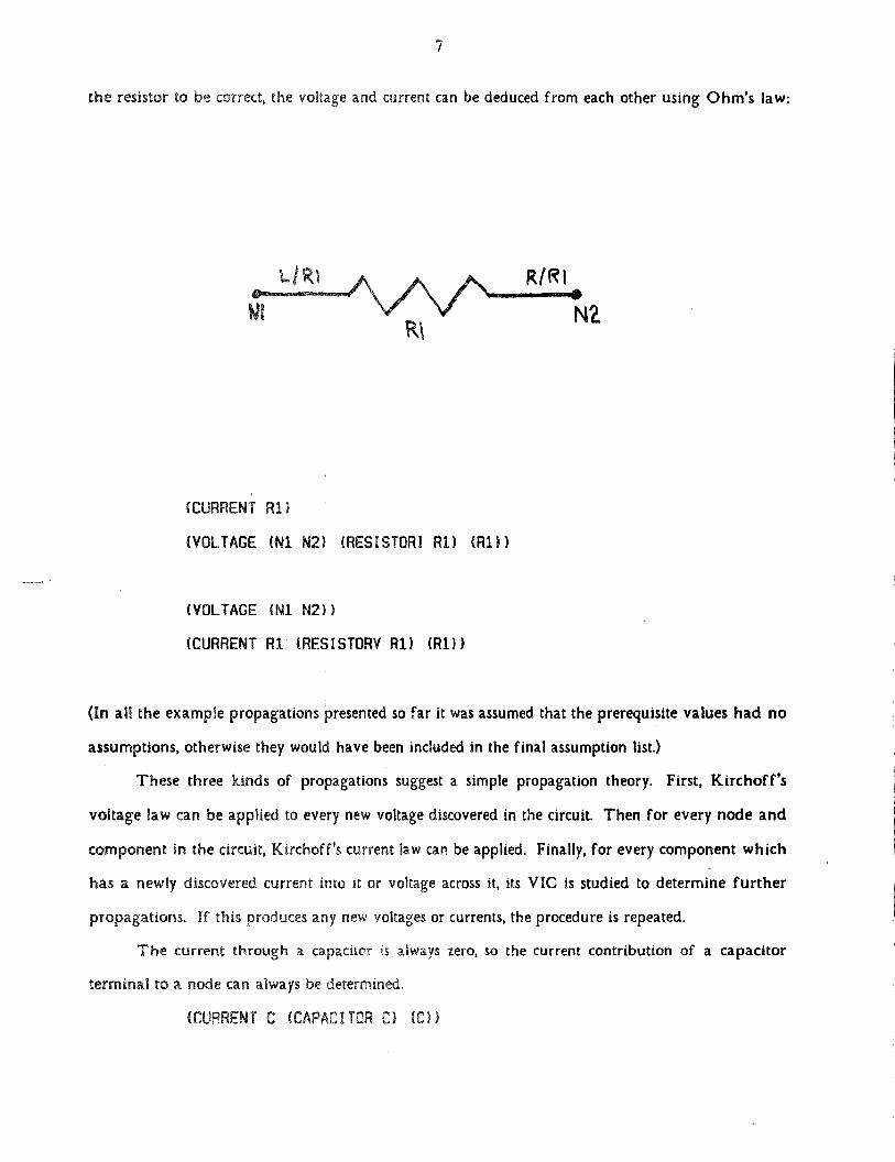
Oneof themost basic typesof thecircuit elementsis the resistor. Assumingtheresistanceof
TI3
7
theresistor to be correct, thevoltage and currentcan be deducedfrom eachotherusing Ohm’s law:
(CURRENT Ri)
(VOLTAGE (Ni N2) (RESISTOR! Ri) (Ri))
(VOLTAGE (Ni N2))
(CURRENT Ri (RESISTORV Ri) (Ri))
(In all the examplepropagationspresentedso far It wasassumedthat theprerequisitevalueshad no
assumptions,otherwisethey would have been included in the final assumption list.)
These three kinds of propagations suggest a simple propagation theory. First, Kirchoff’s
voltage law can be applied to every new voltage discovered in the circuit. Then for every node and
componentin the circuit, Kirchoff’s currentlaw can be applied. Finally, for every component which
has a newly discoveredcurrentinto it or voltage acrossit, its VIC is studied to determine further
propagations.If this producesany new voltagesor currents,theprocedure is repeated.
The current through a capacitoris always zero, so the current contribution of a capacitor
terminal to a node can always be determined.
(CURRENT C (CAPACITOR C) (C))
8
Similarly, the voltage acrossa closedswitch is zero.
(VOLTAGE (Ni N2) (SWITCH VR) (VR))
The remainingcomponentsare semiconductordevices and these are very different from
those previously discussed. Although the VIC’s for transistors,diodes and zener diodes can be
modeled by one nonlinearequation,thesedevicesare usually thought of ashaving a number of
distinct regions of operation,eachregion having a simple linear VIC. The region of operation
mustbedeterminedbeforeany VIC canbe used.
The diode Is the simplestkind of semiconductordevice. The only thing we can say aboutit
in oursimple propagationtheoryIs that if it Is backbiased,thecurrentthroughit must be zero.
(CURRENT 0 (0100EV) (0))
For the zenerdiode we can propagatemore values. If the current through a zenerdiode is
greaterthansomethreshold,thevoltageacrossit must be at its breakdownvoltage.
(VOLTAGE Z (ZENERI) (Z))
If’ thevoltageacrossa zenerdiodeis less than its breakdownvoltage,the current through It must be
zero.
(CURRENT Z (ZENERV) (Z))
The transistor is the most difficult of all devIcesto dealwith. This is both becauseIt has the
peculiardiscontinuouscharacteristicsof a semiconductor device and because It Is a three-terminal
device, If the currentthrough any of thetransistor’sterminalsis known, the current through the
other terminalscan be determinedusing the betacharacteristicsof the device(except in the case in
which it is saturated).Furthermore,if thevoltageacrossthe base-emitterjunction Is less than some
threshold(.55 volts for silicon transistors),the current flowing through any of Its terminalsshould
bezero also.
(CURRENT C/Ui (BETA Ui B/Ui) (01))
(CURRENT C/Ui (TRANOFF 01) (01))
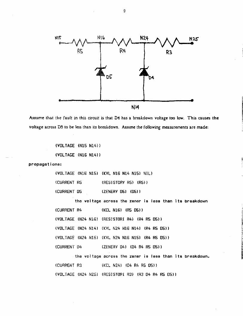
Having experts for each component type as has been just described makes It possible to
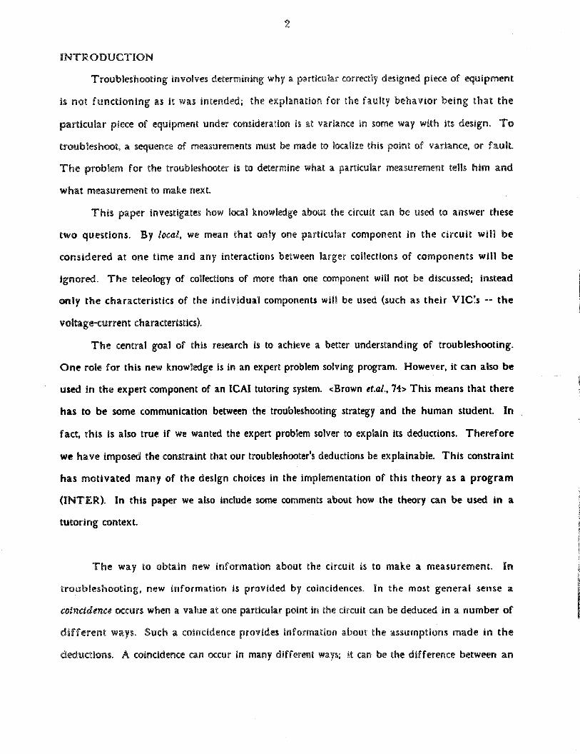
propagate measurementsthroughout the circuit. As an example, consider the following circuit
fragment:
9
Assumethat the fault in this circuit is that D4 has a breakdown voltage too low. This causes the
voltage acrossD5 to be lessthan its breakdown. Assumethe following measurementsare made:
(VOLTAGE (NiS Ni4})
(VOLTAGE (Ni6 N14))
propagations:
(VOLTAGE (NiG NiS) (KVL N16 N14 NiS) NIL)
(CURRENT RS (RES!STORV RS) (RS))
(CURRENT OS (ZENERV OS) (OS))
the voltage across the zener is less than its breakdown
(CURRENT R4 (KCL NiB) (RS 05))
(VOLTAGE (N24 NiB) (RESISTOR! R4) (R4 RS OS))
(VOLTAGE (N24 N14) (KVL N24 NiB Ni4) (R4 RS 05))
(VOLTAGE (N24 NiS) (KVL N24 NiB Ni5) (R4 RS 05))
(CURRENT 04 (ZENERV 04) (04 R4 RS 05))
the voltage acroeB the zener is less than its breakdown.
(CURRENT R3 (KCL N24) (04 R4 R5 OS))
(VOLTAGE (N24 N25) (RESISTOR! R3) (R3 04 R4 RS OS))
I0
(VOLTAGE (N25 N14) (KVL N25 P424 P414) (R3 04 R4 AS 05))
(VOLTAGE (P425 NiB) (KVL N25 P424 NiB) (R3 04 R4 RS OS))
(VOLTAGE (P425 NiS) (KVL N25 P424 NiS) (R3 04 R4 RS OS))
The propagation proceeds one deductionat a time; never Is It necessary to make two
simultaneous assumptions in order to get the next step in the propagationchain, since the
propagationcan always go throughsomeintermediatestep.
A SIMPLE THEORY OFTROUBLESHOOTING
This section examines how the propagation strategy of the previous section can be used to
troubleshoot the circuit. The ideas of contradictions and corroborations between propagations will
be used to show how the propagator can be used to help In troubleshooting the circuit. In this
simple theory we will assumethat coincidencesoccur only between propagated values and actual
measurements.
The meaning of the coincidences depends critically on the kinds of assumptions that the
propagator makes. For the coincidencesto be of interest every assumption made in the derivation
must be mentioned, and a violation of any assumption about a component must mean~that
component Is faulted. Then, when a contradiction occurs, one of thecomponentsof the derivation
must be faulted. Furthermore, if the coincidence was a corroboration, all the components about
which assumptionswere madeareprobably unfaulted.
The usefulnessof’ thecoincidencedependscritically on how many faults the circuit contains.
The usual caseIs that there is only one fault In the circuit. Even the casewhere there is more than
one fault in the circuit, the approach of initially assuming only a single fault in the circuit Is
probablya good one.
If thereIs only one fault in the circuit, all thecomponentsnot mentionedin thederivation of’
the contradiction,must be unfaulted. If a corroboration occurs, all the components used In the
derivation can be assumedto be unfaulted. In a multiple fault situation thesewould be invalid
deductions: In a contradictiononly one of the faulted componentsneedbe involved and in a
corroboration,two faultscould cancelout each otherto producea correct final value.
II
if, In the propagationexampleof the previoussection,the voltage between N25 and NH was
discoveredto contradictwith thepropagatedvalue,one of R3, D4, R4, R5 and D5 must be faulted.
But, If the values were in corroboration,all the componentswould have been determined to be
unfautted.
Now that the fault hasbeen reducedto one of R3, D4, R4, R5 and D5, the propagationscan
be usedto determinewhat measurementshould be taken next. The best sequence of measurements
to undertakeIs, of course,the one which will find the faulted component in the fewest number of
new measurements.Assuming that the relative probability of which component is faulted Is not
known, the best strategyIs a binary search. This is doneby examining all propagations In the
circuit, eliminating from their assumptionlists componentsalready determined to be correct, and
picking a measurementto coincidewith that propagationwhosenumber of assumptions is nearest to
half the numberof possIblyfaulted components.
In the examplethere are five possibly faulted components, hence the best propagations to
choose,arethosewith two or threeassumptions.That meanseither measuring the current through
R4, voltageacrossD4, the voltageacrossR4 or thevoltagebetweenN24 and Nl5.
(CURRENT R4 (KCL NiB) (R5 OS))
(VOLTAGE (P424 NiB) (RESISTOR! R4) (R4 RS 05))
(VOLTAGE (P424 N14) (KVL N24 NiB N14) (R4 RS OS))
(VOLTAGE (P424 NiS) (KVL N24 NiB NiS) (R4 AS OS))
All the other measurements, In the worst case, can eliminateonly one of the possibly faulted
components from consideration,
The current through R4 is measured. This coincidence is a corroboration; so R5 and D5 are
verified to be correct. Therefore one of R3, D4 and R4 mustbe faulted. This leaves the following
interesting propagations.
(VOLTAGE (P424 N16) (RESISTOR! R4) (R4))
(VOLTAGE (P424 P414) (KVL P424 NiB N14) (R4))
(VOLTAGE (P424 P415) (KVL N24 NiB NiS) (R4))
(CURRENT 04 (ZENERY 04) (04 R4))
12
(CURRENT R3 (KCL P424) (04 P4))
At this point there are too few possible faults to make a binary search necessary. Any measurement
which would coincide with any propagation having P.3, D4 or P.4 asassumptions,but not all three
at once, Is a good one. Onesuch measurementis thecurrentthrough D4. In theactual circuit D4
has its breakdown voltage too low so it is drawinga greatdealof current. The propagator deduced
the current should be zero. This contradiction would Indicate that R3 was verified since It was not
Involved. Two possible faults remain; P.4 and D4. P.4 could be faulted high. D4 could be faulted
low. Measuring anyone of the following will indicate that D4 is faulted:
(VOLTAGE (P424 NiB) (RESISTOR! P4) (R4))
(VOLTAGE (N24 P414) (KVL P424 NiB P414) (P4))
(VOLTAGE (N24 NiS) (KVL P424 NiB NiS) (P4))
UNEXPECTEDCOMPLEXITIES OFTHESIMPLE THEORY
The discussion of the previous section presents an interesting and, on the surface,very simple
schemefor troubleshooting. Unfortunately,the entire approachis fraughtwith difficult problems!
This section deals with some of these problems and attempts to provide a solution to them within
the original framework. Such an investigation wIll clarify thedeficienciesof using only local circuit
knowledgefor troubleshooting.
Basically, three kinds of problems arise. First, the handling of corroborations and
contradictions leads to faulty assertionsin certain situations and thus must be examined much more
closely. Second, it will be shown that the propagation scheme, the knowledge contained In the
•experts, and the troubleshooting strategy are all incomplete. Each of them cannot make certain
kinds of deductionswhich one might expect of them in the framework that has been outlined.
Finally, accuracyis a problem; all components and measurements have an error associatedwith
them (If only a truncationor roundoff error), and these causemany kinds of difficulties.
The natureof corroborationsrequirescloser scrutiny. It has already been shown that every
componenton which a derivation dependsIs in the assumptionlist of that derivation,so a
contradictionlocalizesthe faulted componentto one of thosementionedin the assumptionlist. For
13
corroborations, the simple troubleshooting scheme used the principle that a coincidence indicated
that all of the componentsin the assumptionlist were cleared from suspicion. This principle must
be studiedwith much greaterscrutiny,as thereare a number of casesfor which it doesn’t hold.
In order to do this we must examinethe precisenature of the propagations, and, more
importantly, examine the relation betweena single value used in a propagation with the final
propagated value. Consider a propagated value derived from studying thecomponentD. Let the
resulting current or voltage valuebe jtD). The propagatoris entirely linear; so the propagated
value at any point can be written as a linear expression of sums of products involving measured
and propagated values. For every component,current and voltage vary directly with each other and
not inversely. Hence, in the expression for the final propagated value,J(D) can never appear in the
denominator.So the final value can be written as:
value —f(D) ~ + b
Where a and b are arbitrary expressionsnot involving D. The relation betweenjtD) and the final
propagated value is characterized by a. By studying the nature of componentexperts, the structure
of a can be determined. Every expert derivesJTD) either by multiplying the incoming value v(D)
by a parameter, or by applying a simple comparison test to the v(D). As many such comparison tests
can be involved in a single propagation,each propagationcan have a predicate associatedwith it
indicating what conditions must be true for the propagationto hold. With both kinds of
propagationsthere is a problemif a is zero. In that case,J(D)hasno influence on the final value
and so a coincidencesaysnothing about thevalidity offiD).
A corroboration with a propagation involving a predicate only indicates that the incoming
value v(D) of the predicate lies within the tested range, thus saying little about the assumptions
which wereusedto derivev(D). Note, however, that in a contradiction the predicate may be testing
an erroneousvalue, and thus v(D) might be incorrect. We shall call these assumptions, which
corroborations do not remove from suspicion, the secondaryassumptionsof the propagation, and the
remaining,the primary assumptions.
The situation for which a is zerocan be partially characterized. Using the sameassumption
more thanoncein a propagationis relatively rare. In sucha single-assumptionpropagationa must
14
bea singleterm, consistingof a productof parameters(resistances,betas,etc.) or their inverses,and
sinceno circuit parameteris zero, a cannotbe zero.
If multiple assumptions about D aremadein a single propagationa may becomea sum, and
hence possibly zero, so another argument must be used. Every occurrence of an assumption about D
in a propagationpossibly introducesanotherterm to a. Eachof theseterms must itself be a product
of’ parameters. Unfortunately, we cannot prove that a,sO is impossible, but can only appeal to a
somewhat heuristic argument. Consider the case where a is zero. By the previous argument a is
only a function of circuit parameters and so Is independent of any measurements. That means
whatever valueJ(D) has, or even whatever value is actually measured; that value, no matter how
extreme, has absolutely no influence in our propagation scheme on the final propagated value.
That seemsabsurd, so a must never be zero. In other words, a specifies the degree of coupling
between two values in the circuit and It seemsimpossible that two values in the circuit are
• completely decoupled. In the casewhere a is small but not zero (i.e. weak coupling) accuracy issues
becomecritical, but thesewill be discussedlater.
The propagation schemecannot make all the propagations that one might reasonably expect.
Incompletenessof this type manifests itself in two ways. One is just a problem of circuit
representation, and the other is an Inherent problem of the propagator. In both certain obvious
propagationsare not made.
Kirchoff’s current law can apply to. collectionsof componentsand nodes, not just single
components and nodes. Recognizing relevant cutsets in the topology of the circuit is a tedious (yet
performable) task. Circuit diagrams usually presenta visual organization so that such cutsets (and
teleological organization) becomeclear.
The processof propagation as outlined consists of’ using a newly discovered value to call an
expertwhich can use that value to make new discoveries. The expert then ‘looks at the
environment, and from this deducesnew values for the component about which it is an expert.
The communication with the environment always involves numeric values. Experts cannot
communicatewith each other, nor can they handle abstract quantities. Furthermore, propagation
15
stopswhena coincidenceoccursand iteration toward an accuratesolution is never attempted.
This entire schemeis motivated by what we see in human troubleshooters, yet the strategy
has some very surprising limitations. The fact that only one expert is invoked at any one time
meansthat only one assumptioncan be madeat any step in the propagationprocess. This means
that propagationswhich requiretwo simultaneousassumptionscannotbe made. Most propagations
which require more than oneassumptiondo not requiresimultaneous assumptions since they can be
derivedusing someintermediatepropagation(e.g. all thepreviouslydiscussedexamples).
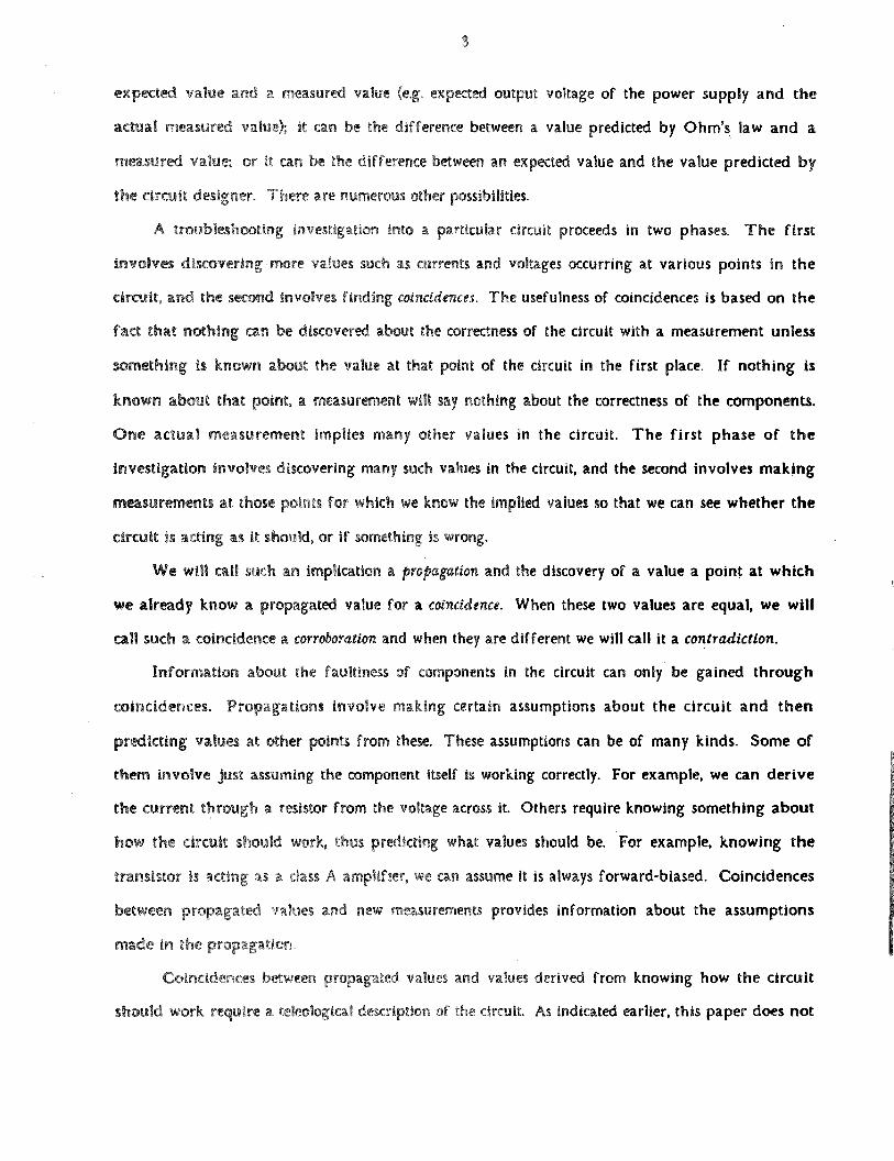
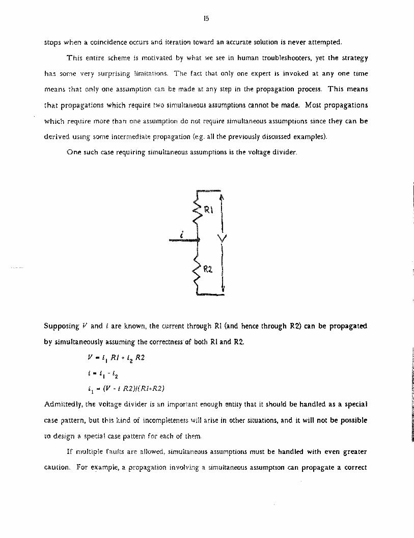
Onesuchcaserequiringsimultaneousassumptionsis the voltagedivider.
SupposingV and I are known, the currentthrough Ri (and hence through P.2) can be propagated
by simultaneouslyassumingthecorrectnessof both RI and R2.
V 11 Ri + R2
~ ii t2
(V - t R2)I(Rl+R2)
Admittedly, the voltage divider is an importantenoughentity that it should be handled as a special
case pattern,but this kind of incompletenesswill arise in othersituations,and it will not be possible
to design a specialcasepatternfor eachof them.
If multiple faults are allowed,simultaneousassumptionsmust be handled with even greater
caution. For example,a propagationinvolving a simultaneousassumptioncan propagatea correct
V
R2.
16
value even though both components involved in the assumptionswere faulted. In the caseof a
voltage divider, the resistance of both RI and P.2 could shift without affecting the voltage at the
tap~ yet the voltage divider would present ar~ erroneous load to the voltage source to which it was
connected.
Due to this Inherent incompleteness In the propagator, coincidences can also occur between
propagated values. This is much more complicatedthanthe coincidenceswe havebeen considering
since both propagationshaveassumptionsthat haveto be examined. If one of the propagations
hasno unverified assumptions,the coincidencecan be handledas if it were betweena propagated
valueand an actualmeasurement.However,if both propagationshaveunverified assumptionsthe
coincidencebecomesfar more difficult to analyze. The effectsof suchcoincidencesdepend
critically on whether the intersection of theunverified assumptionsin eachpropagationis empty or
not. If’ the Intersectionsis empty, a contradictionreducesthe list of possible faults to the union of
the assumptionsusedIn thepropagations,and a corroborationindicatesthat the valuein questionis
thecorrectone,and can be treatedas two separatecorroborationsbetweenpropagatedand measured
values.
The case of a nonempty intersection Is the most difficult. If the coincidence was a
corroboration, a fault in the Intersection could have caused both propagations to be incorrect yet
corroborating. Even so, somethingcan be said about the disjoint assumptions in the propagations,
since if there wasa fault In one of the disjoint primary assumptionsit must have causeda
contradiction; thus all the disjoint primary assumptionscan be verified to be correct. If the
coincidencewas a contradiction,the list of possibly faulty componentscan be reducedto the union
of the assumptions.In this caseit is very temptingto remove from suspicion all those components
mentioned In the intersection, because this would capture the notion that correct propagations from
a single (albeit incorrect) value must always corroborate each other or, equivalently, that each point
in the circuit has only two values associated with It: a correct value and a faulted value (which Is
predicted by the propagator).
Unfortunately that analysis is not valid. Considera feed-backloop. A faulted value is
propagated Into this feed-back loop, the feed-back loop propagates a value completely aroundthe
17
loop and contradictswith the valuewe enteredthe loop with. Either the feed-backloop is faulted,
or theInitial valuewe enteredthe loop with was incorrect,thus by thenatureof feed-backgiving a
contradiction when that valuewas propagatedcompletely around the loop. (Not every feed-back
loop exhibitsthis property,however,althoughit is easyenoughto constructonethat does.)
All measurementsin the circuit and all circuit parametershave errors associatedwith them.
Even if perfectmeasurementsare assumed,truncationand roundoff errorswould still cause
problems. One way to view the problemis to study the size of a relativeto the error In b. If a is
smaller than the error In b, a largeerror in someflD) could be undetected.Again we see the
greatestproblem lies with corroborations.In a corroboratingcoincidencewe must makeabsolutely
surethat an error in any of the verified assumptionscould havebeendetectedin thevalue(i.e., a is
not too small).
There is a simple partial solution that works in most cases. Insteadof propagating numeric
valuesthrough thecircuit, we propagatevaluesandtheir tolerances,or just ranges of values. each
measurementand circuit parametercould havea toleranceassociatedwith it, and the arithmetic
operationscould be modified to handlerangesInsteadof numeric values. Insteadof computing a
and Its tolerance,the propagatorcould note wheneveran error in someIncoming value could be
obscuredin larger errors in other values. This is required since errors in parametersand
measurements are usually percentages, and thus adding a largevalue and a small value will often
obscure an error in the small value. Since suchproblemsoccur only with addition and subtraction
of ranges. KVL and KCL arethe only expertswhich need to be directly concerned with the
accuracyissue.
Assuming that errors in values are roughly proportional to their magnitude, those
propagationsinvolved in a sum whose magnitude is less than the error in the final result should
not be verified in a corroboration of the final value. (As this assumptionis not always true, some
assumptions may not be verified in a corroboration when they should be.) KVL and KCL can
easily check for such propagations. Fortunately, a category for assumptions which should not be
verified in a corroboration has already been defined: the secondaryassumptions. So, primary
18
assumptionsof the Incoming values Into a Kirchoff law expertmay becomesecondaryassumptions
of the final result.
As usual, this theoryof’ handlingaccuracyhassubtleproblems. If’ theonly possibleeffect of
a particularflD) was describedIn a propagation,then no matter how Insignificant its contribution
was to the final value,a coincidenceshould verify D since it wouldn’t matterIn such a caseif D
were faulted or not. Furthermore,the propagationthroughcertain componentsis so discontinuous
that no matterhow insignifIcant Its propagatory contribution Is, a fault in the final value would so
greatly affect the propagation that the assumption in questionshould really be treated as a major
assumption. An example of the former is a switch In serieswith a resistor, and an example of the
latter is a zenerdiode contributingzerocurrentto a node.
Consider the caseof a resistor in serieswith a switch. The only contributionof that switch to
the circuit Is in the voltage across the switch and the resistor. A voltage acrossa closed switch is
zero; so unless the resistance of the resistor is zero, the switch becomesa secondary assumption of
the final voltage. Unfortunately, a corroboration with that voltage should indicate the switch was
acting correctly.
SImilarly, a zener diode contributing zero current to a node will always become a secondary
assumption of the KCL propagation. But, a corroboration should indicate that zener was
functioning correctly. That is becausethis propagation would not even have been possible if the
voltage across the zener was near Its breakdown. A heuristic solution to this problem is not to
secondarizepropagations with zero value which were just propagated from discontinuous devices.
This, of course, makes the teleological assumption that the discontinuouscomponent makes a
significant contribution whenever it Is contributing a non-zero value, as is almost always the case
with theswitch,diode,zenerdiodeand transistor.
Accuracy brings along other problems, as testing for equalitybetweenranges becomes a
rather uselessconcept. A simpleworkablestrategyis to usea rough approximation measuresuch as
acceptingtwo rangesas equal if thecorrespondingendpointsof the two rangesarewithin a certain
percentageof eachother. More satisfactorily,the actualwidth of the range should also enter into
considerationso that if oneend of the rangeis extremelysmall relative to theother, a much more
19
liberal percentageIs usedto comparethesmallerendpoints. Onecertainlywould want the range(0
I] to be roughly equalto [IE-6 , 1]. A coincidencecan thus be of threekinds; either the rangescan
be approximatelyequal (or just significantly overlapping),which is a corroboration,or the ranges
can be disjoint, which is a contradiction,or the rangescan overlap but not significantly, which
providesno informationat all.
The following simple algorithm implementstheseideas. A tolerancefor the comparisonIs
computedby choosingthe minimum width if the widths are very different and choosing half the
width if the widths areapproximatelythe same. Dependingon the circuit and whetherthe
coincidenceIs betweenvoltagesor currentsa minimum toleranceis specified. The minimum
tolerancefor a typical circuit is .1 microamperesand .1 volts. Then the differencesbetweenthe
correspondingendsof therangesaredetermined.. If both differ within thetolerance,the valuesare
determinedto be corroboratory. For example, [.1 , .2] volts and (.15 , .3) volts are judged to be
corroboratory. If only one side is within tolerancethe toleranceis relaxed by 50~and the failing
side Is checkedagain. If this still doesnot match,we cannotreally claim a corroboration; instead
we can only say that one value .cpltts the other. For example,[0 , I] splits [0 , 10]. The two
remainingcasesoccur whenthevaluesarecompletelydisjoint (e.g. (0 , 1] and (3 , 4]) and when they
containeachother(e.g. (0 , 6] and (3 , 4]). Thecontainmentcaseis treatedas a split. Rangesare
considereddisjoint only If thethey differ by greaterthan the tolerance. If noneof theseconditions
aremet, the coincidenceis neithera corroborationnor a contradiction. For example, (0 , .1] volts
and (.2 , .3] neIthercontradictnor corroborate. This algorithm is only a simple attemptat defining
equIvalenceof ranges,and someof the parametersmay have to be tuned for specificcircuits.
A comparisontest betweentwo rangescan havefive results: (1) values contradict, (2) values
corroborate,(3) first valuesplits second,(4) secondvaluesplits first, and (5) no comparisonpossible.
The lastalternativeraisesthepossibility that it may be useful to propagatetwo independentvalues
for the samequantity! The splitting possibilitiescan be intelligently dealt with. If the value for A
splits the valuefor B, then if A is valid, B must be valid, but not conversely. For example,since
A:(3 , 4] splits B:(0 , 101 the validity of A implies the validity of B. But if B were valid, A might be
(7 , 8) which still splits B but contradictswith theoriginal [~,4J. If A is not known to be valid, we
20
must wait till It is proven before using this Information. However,in a single fault theorya very
interesting deduction can still be made. It is easier to see in formal terms: A splitting B really says
valid(A)~valid(B),while A corroboratingB says valid(A)-valid(B). Consider valid(A)Dvalid(B). If
the assumptions of A and B are not disjoint, construct a B* that doesnot mention the common
assumptions. Now va1id(A)~vaUd(B*)also implies invalid(B~)Dinva1id(A).But the assumptions of
B* and A are disjoint and the circuit can have only one fault. Hence B~~cmust be perfectly correct.
In summary,the split of B by A in a singlefault theory Implies all the assumptions involved with B
arecorrect (i.e. a corroborationof B with truth) and nothing about the assumptionsof A. This
correspondswith our intuition; a split is a kind of corroborationin which one of’ the propagations
Is much strongerthan the other,and as such the corroboration only commentson the weakerof the
two propagations.
Although the range mechanismwas introduced to handle errors In measurementsand
componentparameters,It can also be usedto dealwith new kinds of propagationsthat would have
been impossiblein the simple scheme. Noticing that the collector currentof a transistor is large
leadsto the deduction that its base-emitter voltage must be between .5 and I volt, With the range
mechanism this kind of propagation can now be included: propagate the range [.5 , I). There are
many possible uses for this idea. Every diode could propagate a non-negative current through
itself. Every transistor could propagate a base-emitter voltage of less than I volt. The voltage at
every node could be asserted to be less than the sum of the voltage sources in the circuit. More
interestingly,it could handlethe problem of havinga rangepropagatedover a discontinuous
device: a f-I , +1) current range propagated into a diode should haveits lower limit modified to 0
(i.e. (0 , +1]).
When a significant propagationoccurswhich overlapsa testpoint of a discontinuous
component,the best strategyis to Interpret that measurementto have too wide an error associated
with It and stop the propagationthere. In general,when error tolerancesin propagatedvalues
becomeabsurd(a significant fraction or multiple of the central value) the propagationshould be
artificially stopped.
21
When a coincidenceoccurredIn the old propagation schemethe propagations stopped.
There was no advantage In also propagatingthenew value. However,when ranges are involved,
the new propagation might be better than the old one. The range with the smallest error Is the
better of the two. For example, the values (0, 10] corroborates with U, 2], yet the latter value s~iould
provide much more Information if It were propagated.This meansthat when a coincidence
between ranges occurs, the better of the two propagationsmustnot be stopped from propagating.
There remain certain characterIstics of the devices that are not captured in the propagation
scheme. These are the maximum ratings of the components. The power dissipation of a transistor
cannot exceed Its power rating, the voltage acrossa capacitor cannot exceedits breakdown voltage,
the power dissipation In a resistor cannot exceed its wattage rating, etc. To a large extent thesecan
be captured by simple modifications of the component experts. Each expert could check whenever
it was invokedwhetherany ratings about the component were exceeded. If the component expert
detects that a rating has been exceeded it must treat it as a contradiction. The maximum rating, of
course, depends only on the component itself.
A contradiction casts suspicion on all the assumptions of the contradicting propagations.
More careful examination of the contradiction may restrict the possiblefaults even further.
Knowing that the current In a resistor Is higher than expected indicates that its resistance has
shifted downwards. If a contradiction suggeststhere Is too little current through a capacitor, we
know the capacitor cannot be contributing to the fault.
We must tackle the problem of how to scanback through the propagation to determine what
faults In the components could have caused the final contradiction. Of course, a straightforward
way to do this would be to compute a for every componentJ(D) involved in the propagation. For
every two-terminal componentthe possiblefault can be immediately determined from a (unless of
coursewe have the inaccurate case where the range for a includes zero). The only three-terminal
device, the transistor, requires a more careful examination as it hasmany possiblefault modes,and
a singleconsiderationof a propagationfrom it may not uniquely determineIts fault mode.
22
Continuing In the spirit of the original propagation scheme, a method different from that of’
computing a should be used. The following simple schemehas difficulties only in certain kinds of
multiple assumption propagations. The contradiction Indicated that the propagation was in error
by a shift in value in a certain direction. This shift can be propagated backwards through all the
experts except KCL and KVL. The Kirchoffs’ laws experts involve addition, so each of the
original contributors to the sum must be examined. For those contributors whose (unverified)
assumption list doesnot intersect with any of the other assumption lists, the shIft can be propagated
back, after adding the appropriate shift caused by the remaining contributors. For those
contributors with intersecting contributions, it must be determined for each of the intersecting
componentswhether all contributions of all the possiblefaults do not act againsteach other (e.g. will
a shift In the resistance of the component both increase a current contribution to a node and
decreaseIt through another path?). For such canceling intersections, nothing can be said about the
Intersecting component. All this doesis capture qualitatively whether the signsof the terms of’ a are
different and thus canceling. It should be noted, that If it really turns out to be the case thata a
can be zero,such a schemecould be used at least to eliminate faulty verifications from taking place,
again at the costof sometimesnot verifying provably unfaulted components.
IncompletenessIn the propagation schemeintroducesincompletenessin the troubleshooting
scheme. Even if the propagation schemewere completethe troubleshooting schemewould be
Incomplete, since the earlier answer to what Is the next best measurement Is inaccurate. The
measurementwhich reduces the list of’ possible faults by the greatest number is not necessarily the
best measurement. Future measurementsmust also be taken into consideration, a poor first
measurementmay set the stagefor an exceptionally good secondmeasurement.
The choice of best measurementdepends of course on what is currently known about the
circuit. The most general approach would be to try every possible sequenceof hypothetica’
measurementsand choosethe first measurement of the best sequenceas the next measurement.
Again, that would be an incredible, and unnatural computation task. The current troubleshooting
schemedoes not try to generateall possible sequences,but only considers making those
measurementsaboutwhich It alreadyknows something(so to producea coincidence).
Sinceonly measurementsat points aboutwhich something is explicitly known areconsidered,
the Information provided by coincidencesbetween solely propagatedvalues (the result of
incompletenessin the propagator)cannotenterinto consideration. Thus the basicapproachof the
troubleshooterIs to makeno hypotheticalmeasurementsand look only at thosepropagationswith
unverified assumptionsaspredictionsto try to coincidewith. Unexpectedinformation, suchasthat
provided by coincidencesbetweenpropagatedvalues,cannotbe consideredin that paradigm
(althoughmakinghypotheticalmeasurementswould handlethis problem).
If we are only preparedto look aheadonemeasurement,our original searchschemeremains
reasonable.The binary searchfor the best measurementmust, of course, be reorganized. Sincea
corroborationmay eliminatedifferent numbersof componentsfrom suspicion than a contradiction,
the searchIs not purely binary. A workablesolution is to just take the averageof the number of
componentswhich would be verified in each case as the measurement’s score. Then that
measurementwhosescorewasnearestto half thenumberof faulted componentscould be chosen as
the next measurement.
Thereremainsthe issue of generatingan explanationfor this choice. Although the above
argumentfor deriving a futurechoice of measurementcould be madeunderstandable to humans it
doesnot alwaysadmita very good explanation. A largepartof theexplanationfor a future choice
of measurementinvolves indicating why a certaincomponentcannotbe faulted. Oncea component
is eliminated from suspicion for any reason it is neverconsideredagain. However,a later
measurementmight give a considerablybetterexplanationfor its non-faultiness. The problem of
generatinggood explanations, of course, also must take Into accounta model of the student and
whathe knowsabout the electronics and the particular circuit in question.
The above schemefor selectingmeasurementsdoes not take into account how “close~the
measurementis to the actualcomponentsin question. For example,a voltage measurementacross
two unverified resistorsis just as good as a measurementmany nodesaway which also hasonly
thosetwo resistorsasunverified assumptions.Fortunatelythesecan be easily detected: just remove
from the list of possiblemeasurementsall thosewhich are propagatedfrom other elementson the
24
list. Theseare the propagationswhich makeno new assumptionin their most recent propagation
step and involve only one unverified propagation. For examplein the first troubleshooting
scenariothe measuringthe voltage betweenNl5 and N24 was a candidate. SinceKVL makesno
assumptionsand the other voltage betweenN15 and N16 had been alreadyverified this suggestion
should havebeenthrown out.
SOME ILLUSTRATIVE EXAMPLES
The following are somedebugging scenarios to illustrate the ideas of the previous section.
Note that primary and secondaryassumption lists are kept for each propagation.
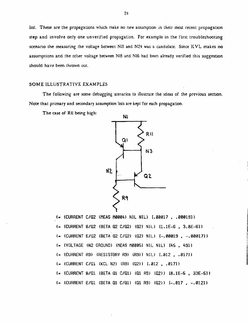
The caseof RU being high:
wz,
(~. (CURRENT C/Q2 (MEAS M0084) NIL NIL) [.80017 , .00819])
(~ (CURRENT BIQ2 (BETA Q2 C/Q2) (Q2) NIL) [1.1E—6 , 3.8E—B])
(~ (CURRENT EIQ2 (BETA Q2 CIQ2) (Q2) NIL) (—.00019 , —.00017])
(- (VOLTAGE (N2 GROUNO) (flEAS 118885) NIL NIL) [45 , 49])
(= (CURRENT R9) (RESISTORV R9) (R9)) NIL) [.012 , .017))
(~ (CURRENT C/Q1 (KCL N2) (R9) (02)) [.812 , .017])
(~ (CURRENT B/Q1 (BETA 01 C/Oil (01 R9) (02)) (8.1E—S , 33E—S])
(~ (CURRENT E/Q1 (BETA 01 C/Q1) (01 R9) (02)) [—.017 , —.012])
QZ
25
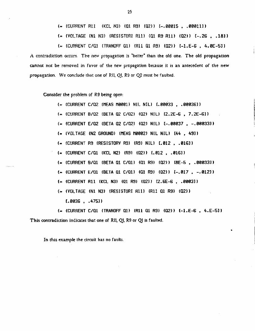
(~(CURRENT Ru (KCL N3) (01 R9) (02)) [—.88815 , .88811])
(~ (VOLTAGE (Ni N3) (RESISTORI All) (01 R9 All) (02)) (—.26 , .18])
(~ (CURRENT C/QI (TRANOFF 01) CR11 01 AS) (02)) (—1.E—6 , 4.OE—S])
A contradiction occurs. The new propagation is ~better~than the old one. The old propagation
cannotnot be removed in favor of the new propagation becauseit is an antecedentof the new
propagation. Weconcludethatoneof RU, Qj, R9 or Q2 must be faulted.
Considertheproblemof R9 beingopen:
(~ (CURRENT
(~(CURRENT
(~ (CURRENT
(— (VOLTAGE
(~(CURRENT
(~(CURRENT
(.‘ (CURRENT
(rn (CURRENT
(~(CURRENT
(~(VOLTAGE
(.8836
(- (CURRENT
C/02 (MEAS 118081) NIL NIL) [.08833 , .88836])
B/02 (BETA 02 C/02) (02) NIL) 12.2E—6 , 7.2E—6])
E/02 (BETA 02 C/02) (02) NIL) (-.88837 , -.08033])
(N2 GROUND) (MEAS 110802) NIL NIL) (44 , 49])
R9 (RESISTORV AS) (AS) NIL) (.012 , .8163)
C/Ui (KCL N2) (R9) (02)) [.812 , .016])
B/Ui (BETA 01 C/Oil (01 R9) (02)) [8E-5 , .08833])
E/Q1 (BETA 01 C/Q1) (01 AS) (02)) (—.817 , —.812])
Ru (KCL N3) (01 AS) (02)) (2.6E-6 , .8883])
(Ni N3) (RESISTOR! All) (Ru 01 AS) (02))
.475])
C/al (TRANOFF 01) CR11 01 AS) (02)) (—1.E—6 , 4.E—S])
This contradiction Indicates that one of Rh, Qj, R9 or Qj is faulted.
In this example the circuit has no faults.
26
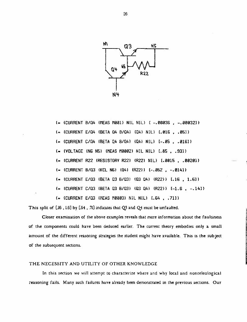
(— (CURRENT B/04 (flEAS 1188i) NIL NIL) C -.08036 , -.88832])
~ (CURRENT E/04 (BETA 04 8/04) (04) NIL) [.016 , .85])
(~ (CURRENT C104 (BETA 04 B104) (04) NIL) [—.05 , .016])
C. (VOLTAGE (N6 N5) (flEAS 118802) NIL NIL) (.85 , .93])
(— (CURRENT R22 (RESISTORV R22) (R22) NIL) [.8015 , .0028])
(‘ (CURRENT B/03 (KCL N6) (04) (R22)) [—.052 , —.814])
(.. (CURRENT E/Q3 (BETA 03 8/03) (03 04) CR22)) [.16 , 1.6])
C— (CURRENT C/03 (BETA 03 8/03) (03 04) CR22)) (—1.6 , —.14])(= (CURRENT E/03 (flEAS M0083) NIL NIL) [.64 , .71])
This split of [.16 , 1.6) by (.64 , .713 indicates that Q~3and Q,4 must be unfaulted.
Closer examination of the above examplesrevealsthat more information about the faultiness
of the components could have been deduced earlier. The current theory embodies only a small
amount of the different reasoning strategies the student might have available. This is the subject
of thesubsequentsections.
THE NECESSITY ANDUTILITY OF OTHER KNOWLEDGE
In this section we will attempt to characterizewhere and why local and nonteleological
reasoningfails. Many such failureshavealreadybeendemonstratedin theprevioussections. Our
R.22.
27
method of attackwill be from two directions. First, problemsinherent in the earlier propagation
schemecan be alleviated with other knowledgeabout the circuit. Second,many of the kinds of
troubleshootingstrategieswe see in humanscannotbe capturedeven by a generalizationof the
proposedscheme. Oneof the basic issuesIs that of teleology. The more teleological information
one hasaboutthe circuit, the moredifferent the troubleshootingprocessbecomes. Currently,most
of the ideaspresentedin this paperso far havebeen implementedin a program so that much of
thediscussionsderivetheirobservationsfrom actual interactionswith the program.
The most arrestingobservationis that the propagatorcannotpropagatevaluesvery far, and
at other times it propagatesvaluesbeyond the point of absurdity. Examining those propagations
which go too far the mostdominantcharacteristicis that either the value itself has too high of an
error associatedwith It, or that thepropagationitself is not relevant to the Issues in question. The
former problem can be more easily answeredby more stringent controls on the errors in
propagations.The latter requiresan idea of localization of interaction. This ideaof a theater of
interactionswould limit senselesspropagation; however,it requiresa more hierarchical description
of thecircuit.
The idea that every measurementmust have a purposepoints out the basic problem: our
troubleshootercannotmakeintelligent measurementsuntil it has,by accident, limited the number of
possiblefaults to a small subsetof all the componentsin the circuit. After this discoveryhas been
made, which the troubleshooter is not given and must make by itself, fairly intelligent suggestions,
can be made. However,as sucha discovery is usually made when the set of possiblefaults is
reduced to about five components,it can only intelligently troubleshootin the last few (two or three)
measurements that are madein thecircuit.
Clearly, many measurementsaremadebeforethis discoveryand the troubleshooter cannot do
anything Intelligent during this period. Still, the propagationschemeand the ideas of
corroborationsand contradictionscan be effectively usedevenduring this period.
The only way intelligent measurements can be made during this period is by knowing
somethingabouthow thecircuit should be behaving. This requiresteleologicalinformation about
thecircuit. For example,just to know that the circuit is faulted and requirestroubleshooting
28
requiresteleology. In the situationswhere the propagatordid not propagatevery far, the problem
usually was that some simple teleological assumptioncould have been made. The voltages and
currentsat many points in the circuit remain relatively constantfor all instantlationsof the circuit,
and furthermoremany of them can be easily deduced(e.g. knowing certain voltage and current
sourcessuch as the power supply, knowing contributionsby certain componentsto be small, etc.).
Propagationcan then proceedmuch further. Of course, the handling of coincidencesrequires
modifications,and a new kind of strategyto deal with teleological coincidencesneeds to be
developed.
Coincidencesprovidedinformation only aboutthe assumptionsof the propagationsinvolved.
Since the only kind of assumptionswe were consideringwere thoseabout the faultednessof
components, the consequencesof violating assumptions were obvious. The consequencesof
violating a teleological assumption is not at all obvious and requires more knowledge about the
circuit. The point Is that the ability the propagate teleological assumptions is just a small step
towards dealing with teleology.
In his thesis Brown <Brown, 76> deals primarily with how to represent and use teleological
knowledge In troubleshooting. Although propagation plays only a small role in his theory, many of
his Ideas addressthe problems that we havebeen discussing in this section.
FUTURE RESEARCH
The previous sections have sketched out the necessityfor more teleological and non-local
knowledge. Since Brown addressed this problem, one obvious direction for research Is to try to
incorporate his Ideas. This direction suffers from two difficulties. First, Brown never implemented
his ideasand thus they require a major effort to becomeactually utilizable. (The troubleshooter
basedon the ideasof this paper(INTER) is working and requiresa practical theory of teleology.)
Second,Brown’s troubleshootingtheory would not be usablein a tutoring context wherethe expert
must beableto understandthe student’stroubleshootingstrategy.
Fortunately,there appearsto be a rather simple strategybasedon the existing propagator
which can be usedto dealwith non-local knowledge. The ideais basedon observationsthat
29
students often reason something like: “If the voltage limiter is off and it should be off, then the
constant voltage source cannotbe contributing to the observedsymptom.” Note that this argument
is not in terms of numerical quantities,but is in termsof statesof the componentsand sections. The
component experts can be modified to determine what statethe componentsare in. These
observations could then be assertedin a data-base.
This collection of assertionsforms a qualitativedescriptionof the state of the circuit. Of
course,the assertions,like propagations,havetheir assumptionsstored with them. Circuit specific
theoremscan then be encodedreferring to assertionsIn the description space. The rule of the
previousparagraphmight be encodedas:
(STATEvoltage-limiteroff) A (CORRECT-STATEvoltage-limiter off)
(OK constant-voltage-source)
It appears that only a small number of such theorems are necessaryto determine what is known
about a circuit from a set of measurements.Thetheoremsare,of course,very circuit specific. Since
only a few of them are be requiredfor any specific circuit the principle is still usable.
The local reasoning strategy isolates the qualitative reasoner from worrying about many of
the idiosyncrasiesof propagating numerical values by describing the circuit in qualitative terms.
This is giving us the opportunity to try many different kinds of qualitative reasoning strategies.
The failings of the local troubleshooting strategy is also showing exactly where this qualitative
reasoning is required.
so
REFERENCES:
<Brown, 74>Brown, A.L., “Qualitative Knowledge, Causal Reasoning, and the Localization of Failures — aProposal for Research,Artificial Intelligence Laboratory, WP-61, Cambridge: M.I.T., I974~
<Brown, 76>Brown, A.L., “Qualitative Knowledge, Causal Reasoning, and the Localization of Failures”,Artificial Intelligence Laboratory, forthcoming TR, Cambridge: M.I.T., 1976.
<Brown & Sussman,74>Brown, A.L., and G.J. Sussman,“Localization of Failures In Radio Circuits a Study In Causal andTeleologicalReasoning”, Artificial Intelligence Laboratory, AIM-Zig, Cambridge: M.I.T., 1974.
<Brown et.al., 74>Brown, John Seely,Richard R. Burton and Alan 0. Bell, SOPHIE: A SophisticatedInstructionalEnvironmentfor TeachingElectronic Troubleshooting(An exampleof Al in CA!), Final Report, B.B.N.Report 279, A.!. Report 12, March,1974.
<Stallman & Sussman,76>Stallman, R.S., and G.j. Sussman,“Forward Reasoningand Dependency-DirectedBacktracking In aSystem for Computer-Aided Circuit Analysis”, Artificial Intelligence Laboratory, AIM-~8O,Cambridge: M.I.T.,1976.
<Sussman& Stallman, 75>Sussman, G.J., and R.M. Stallman, “Heuristic Techniques in Computer Aided Circuit Analysis”,Artificial Intelligence Laboratory, AIM-328, Cambridge M.I.T., 1975.