1
IMPROVEMENT OF POWER QUALITY
USING ISOLATED DISTRIBUTED
GENERATION STATION
DISSERTATION-II
Submitted in partial fulfilment of the
Requirement of the award of
Degree of
MASTER OF TECHNOLOGY
IN
ELECTRICAL ENGINEERING
(POWER SYSTEM)
Submitted by
Registration No:
Under the Guidance of
School of Electronics and Electrical Engineering
Lovely Professional University
Punjab

2
APRIL-2017
CANDIDATE'S DECLARATION
I Richa Chanan, student of M.tech (Electrical Engineering) under school of Electrical and
Electronics Engineering of Lovely Professional University, Punjab, hereby declare that all the
information furnished in this dissertation report is an authentic record of my own work carried out
under the supervision of “Mrs. Preeti Khurana” Assistant Professor, School of Electrical and
Electronics Engineering. The matter presented in this dissertation has not been submitted to Lovely
Professional University or to any other university or institute for the award of any degree.
Signature of the Student
Reg. No. 11502954
Date:
This is to certify that the above statement made by the candidate is correct to the best of my
knowledge.
Signature of the Supervisor
The M.tech Viva-Voce Examination of (Dissertation) has been held on __________ and found
satisfactory/Not satisfactory.
Signature of the Internal Examiner Signature of the External Examiner

3
AСKNOWLEDGEMENT
I would like to express my sincere gratitude to my mentor “Mrs. Preeti Khurana” (Assistant
Professor) for her guidance, encouragement, and support throughout the course of this work. It
was an invaluable learning experience for me to be one of her students. From her, I have gained
not only extensive knowledge but also a sincere research attitude. I express my sincere gratitude
to “Mr. Niraj Kishore” (Assistant Professor) for his invaluable suggestions and constant
encouragement all through the research work. My thanks are extended to my teachers; “Mr. Satish
Julakanti Reddi”, “Mr. Mukul Chanakya”, “Ms. Varsha Jaiswal” and “Mr. Dara Siva
Kumar” who helped me to make it possible.
I would also like to acknowledge the Head of the School of Electrical and Electronics Engineering
and entire teaching and non-teaching staff of the Department for establishing a working
environment and for сonstruсtive discussions. Finally, I am always indebted to all my family
members especially my parents, for their endless love and blessings.
NAME: RICHA CHANAN
REG. NO: 11502954

4
СERTIFIСATE
This is to certify that the declaration statement made by this student is сorreсt to the best of my
knowledge and belief. She is doing Dissertation-II work under my guidance and supervision. The
present work is the result of his original investigation, effort, and study. No part of the work has
ever been submitted for any other degree at any University. The Dissertation work is fit for the
submission and partial fulfilment of the conditions for the award of M.Teсh degree in Electrical
and Electronics Engineering from Lovely Professional University, Phagwara.
Signature and Name of the Mentor:
Designation:
School of Electronics & Electrical Engineering
Lovely Professional University
Phagwara, Punjab
Date:
5
ABSTRACT
Small hydro plant is used as a DG at that places where conventional hydro plant is unable to
generate electricity due to less unavailability of water. It has major advantages over the
conventional nevertheless it has some drawbacks associated to rotor oscillations and unregulated
voltage at generator terminal ought to sudden change in load.
These issues are rectified by using Automatic Voltage Regulator and Power System Stabilizer.
AVR regulates generator terminal voltage and PSS is used to damp out the rotor oscillations.
STATOM is connected with the system to compensate for reactive power demand by the system,
improving overall power quality. It compensates reactive power by injecting quadrature
component of line current into the system with in quadrature phase with the system.
6
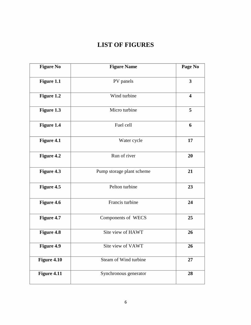
LIST OF FIGURES
Figure No Figure Name Page No
Figure 1.1 PV panels 3
Figure 1.2 Wind turbine 4
Figure 1.3 Micro turbine 5
Figure 1.4 Fuel cell 6
Figure 4.1 Water cycle 17
Figure 4.2 Run of river 20
Figure 4.3 Pump storage plant scheme 21
Figure 4.5 Pelton turbine 23
Figure 4.6 Francis turbine 24
Figure 4.7 Components of WECS 25
Figure 4.8 Site view of HAWT 26
Figure 4.9 Site view of VAWT 26
Figure 4.10 Steam of Wind turbine 27
Figure 4.11 Synchronous generator 28
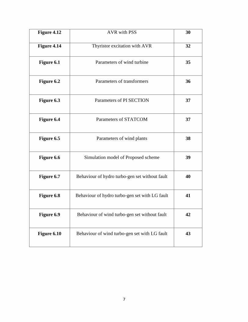
7
Figure 4.12 AVR with PSS 30
Figure 4.14 Thyristor excitation with AVR 32
Figure 6.1 Parameters of wind turbine 35
Figure 6.2 Parameters of transformers 36
Figure 6.3 Parameters of PI SECTION 37
Figure 6.4 Parameters of STATCOM 37
Figure 6.5 Parameters of wind plants 38
Figure 6.6 Simulation model of Proposed scheme 39
Figure 6.7 Behaviour of hydro turbo-gen set without fault 40
Figure 6.8 Behaviour of hydro turbo-gen set with LG fault 41
Figure 6.9 Behaviour of wind turbo-gen set without fault 42
Figure 6.10 Behaviour of wind turbo-gen set with LG fault 43
8
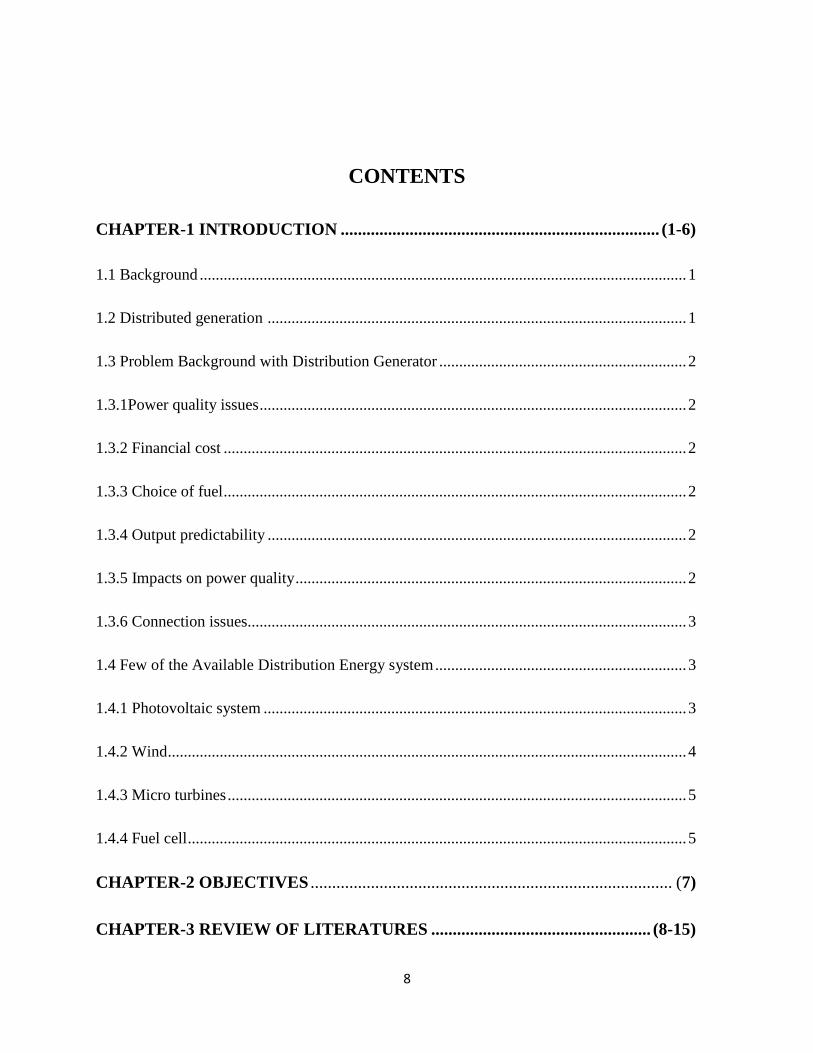
CONTENTS
CHAPTER-1 INTRODUCTION .......................................................................... (1-6)
1.1 Background .......................................................................................................................... 1
1.2 Distributed generation ......................................................................................................... 1
1.3 Problem Background with Distribution Generator .............................................................. 2
1.3.1Power quality issues ........................................................................................................... 2
1.3.2 Financial cost .................................................................................................................... 2
1.3.3 Choice of fuel .................................................................................................................... 2
1.3.4 Output predictability ......................................................................................................... 2
1.3.5 Impacts on power quality .................................................................................................. 2
1.3.6 Connection issues.............................................................................................................. 3
1.4 Few of the Available Distribution Energy system ............................................................... 3
1.4.1 Photovoltaic system .......................................................................................................... 3
1.4.2 Wind .................................................................................................................................. 4
1.4.3 Micro turbines ................................................................................................................... 5
1.4.4 Fuel cell ............................................................................................................................. 5
CHAPTER-2 OBJECTIVES .................................................................................... (7)
CHAPTER-3 REVIEW OF LITERATURES ................................................... (8-15)
9
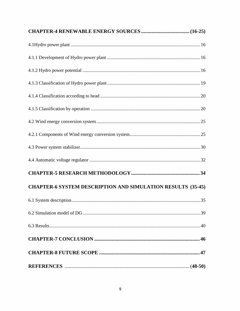
CHAPTER-4 RENEWABLE ENERGY SOURCES ...................................... (16-25)
4.1Hydro power plant .............................................................................................................. 16
4.1.1 Development of Hydro power plant ............................................................................... 16
4.1.2 Hydro power potential .................................................................................................... 16
4.1.3 Classification of Hydro power plant ............................................................................... 19
4.1.4 Classification according to head ..................................................................................... 20
4.1.5 Classification by operation ............................................................................................. 20
4.2 Wind energy conversion system ........................................................................................ 25
4.2.1 Components of Wind energy conversion system............................................................ 25
4.3 Power system stabilizer...................................................................................................... 30
4.4 Automatic voltage regulator .............................................................................................. 32
CHAPTER-5 RESEARCH METHODOLOGY ...................................................... 34
CHAPTER-6 SYSTEM DESCRIPTION AND SIMULATION RESULTS (35-45)
6.1 System description ............................................................................................................. 35
6.2 Simulation model of DG .................................................................................................... 39
6.3 Results ................................................................................................................................ 40
CHAPTER-7 CONCLUSION ................................................................................... 46
CHAPTER-8 FUTURE SCOPE ............................................................................... 47
REFERENCES .................................................................................................. (48-50)
10
CHAPTER 1
1.1 Background
Coming onto the realities worldwide [1,2] a generating unit build up of integrating medium and
small sized units is becoming alternative to power generation. Distributed Generation deployment
on a greater scale caused by greater use of renewable sources is bought into action [3, 4]. The main
concerns over emissions caused by greenhouse effect leading to the global warming and increased
hike in the cost of distribution networks is the drive that caused explorer to dig in its potential.
This Dg’s with small generating unit places numerously near the load centres will contribute and
compensate in electrical power system. [5]. Various benefits have been fetched from DG’s due to
its location close to the consumer end that includes environmental, economic and technical benefits
[6]. Its advantages includes voltage profile improvement, reduction in power loss, deferring T and
D investment, pollution emission offsetting. Grid coupling includes power electronic convertors
in the newest technology unlike usual conventional generators [5] .There are still many challenges
which DG unit faces due to its characteristics for e.g. Low inertia [7,3]. Small DG units comparison
to lager centralised units are preferred since it doesn’t interfere with the power network’s operation
.In respect to it if instead of smaller units larger units are places, it often ends up changing the
power system dynamics of the whole system[5]. The trouble in the power system analysis is due
to the distribution network’s technology advancement and uniqueness in the large scale projects
[3].The DG technology that provides both power and heat generation is the best of its types. Fossil
–fuel generator can be utilised in future for the large scale production [4]. The best among the
technology is still micro turbine and fuel cells both can be used as a hybrid combination or
individually. [8]. Analysing the performance of large DG units and their characters is still to be
undergone.
1.2 Distribution generator-
Direct connection of an electric power source to the distribution network or connection to the
consumer side directly is one of the definitions of Distribution generator [1]. Another definition
proposed by Soderman and Pettersson (2006) defines a complex system of distributed energy
consisting heat storage facilities, various consumers and suppliers, heating pipelines, regional
power transmission lines. Confusion of DG’s with the generation of renewable energy should be
11
clarified perhaps DG’s cannot be used with Non renewable energy sources [16].In earlier times,
near the logical optima or the resource, in large power stations electricity used to be generated.
Transmission via high voltage grid was made and further the distribution was made through
distribution grid of medium voltage.
1.3 Problem Background with Distribution Generator-
1.3.1 Power Quality Issues
Issues related with power quality relate with the presence of harmonic content developed due to
investors and synchronous machine. That causes various distortions at the feeder side. Thus the
power so developed at the frequencies related to harmonics causing the wires to heat up. Such
issue what a great concern at the earlier time with old models of invertors as now PWM invertors
has been introduced and the harmonic content produced by it is much lesser. [17]
1.3.2 Financial costs
The major drawback in settling the plant is its cost. Cost KW is extremely high comparing to
the other sources like nuclear power plant.
1.3.3 Choice of fuel
Choice to select the fuel is not very vast range, it’s typically less. Coal could be replaced with the
gas in the generation based on coal. The cost of primary fuel is much costlier which is mainly
depending upon the present economic scenario of market.
1.3.4 Output predictability
Predicting the output power from DG’s is difficult. Since its dependence of renewable, some
energy generation that is heat driven. There is a party PRP (Programme Responsible Party) which
is responsible for balancing the input and output power by injecting power to the grid and keeps it
in equilibrium. If the party in case failed to keep the balance it is subject to penalty which is
certainly no included in the tariffs of transmission. The consequence has to be bear by market
participants.
1.3.5 Impacts on power quality
Power quality of DG’s is related to its connection and the way it’s been installed. System
frequencies are affected by DG since the absence of frequency control in it. So, the proper planning
is need to done before the installation. DG’s often leads to voltage imbalances aswell. More than
withdraws ARP has to do power injections i.e. 3-4 %. The main focus of DG’s is not let low
12
voltages occur. Therefore, the issues with low voltages are rare but instead weekly high voltage
issues could be seen [10] [11].
1.3.6 Connection Issues
The flow of electric power occurs from high to low voltage grid. Since distributed generator has
many shares so power in this case flows from low to the medium volt Grid. Protection scheme
demand is different for different voltage level. There are various operation modes like Islanding
which is certainly being opted by some of the consumer in the time of outages. Thus, the
requirements should be met by DG’s in under such situations. As soon as the power grid is back
in action it must immediately and smoothly synchronize with the system. [12]
1.4 Few of the Available Distribution Energy system-
1.4.1 Photovoltaic System
Conversion of solar energy into electrical energy with the use solar cell is called photovoltaic
technology. Crystalline silicon forms the semiconductor material that produces electricity by
absorbing sunlight. The ability of photovoltaic system to form usable electrical energy by the solar
conversions determines its efficiency. It ranges from 10% to 15%. The amount of electrical energy
produced depends directly of the surface area of the solar cells. Modules/ Solar Cell configuration
depicts the magnitude of constant DC output. An electronic interface is required to convert DC
into AC which is available for the consumer. DC voltage magnitude boosting is by made by DC-
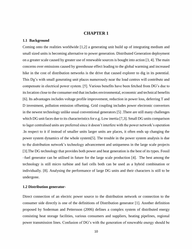
DC convertors. With the use of DC-AC inverters voltage is converted to 60 HZ [13].
13
Figure.1.1-PV panels (NREL 2008).
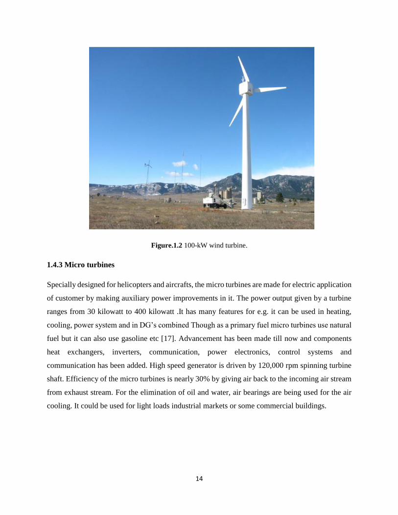
1.4.2 Wind
In the wind turbines, mechanical power formed by the conversion of kinetic energy of wind. The
energy so produced is thus converted into electrical form with the use of generator. Generation of
power is made by synchronous generator or by induction generator. Rotor of generator consists of
a blade that captures the wind. Output power is approx. 10 Kilowatt to 2.5 megawatt. Connection
of generator to the grid is interconnected. Generation of power depends totally on wind blow.
There is thus a need of regular requirement of maintenance of these turbines and cost of fuel is cut
down [14].Wind turbines convert kinetic energy in the wind into mechanical power that can be
converted into electrical energy with a generator. Power is normally generated either with an
induction generator or with a synchronous generator. Synchronous generators are typically
interconnected to the grid through power electronics. Power output is typically between 10kW to
2.5 MW and wind power is captured using a blade that is connected to the rotor of a generator.
The power is generated only when the wind blows. Like PV systems, there are no fuel costs, but
periodic maintenance of the wind turbines is required [14]. A 100 kW wind turbine is shown in
Figure below.
14
Figure.1.2 100-kW wind turbine.
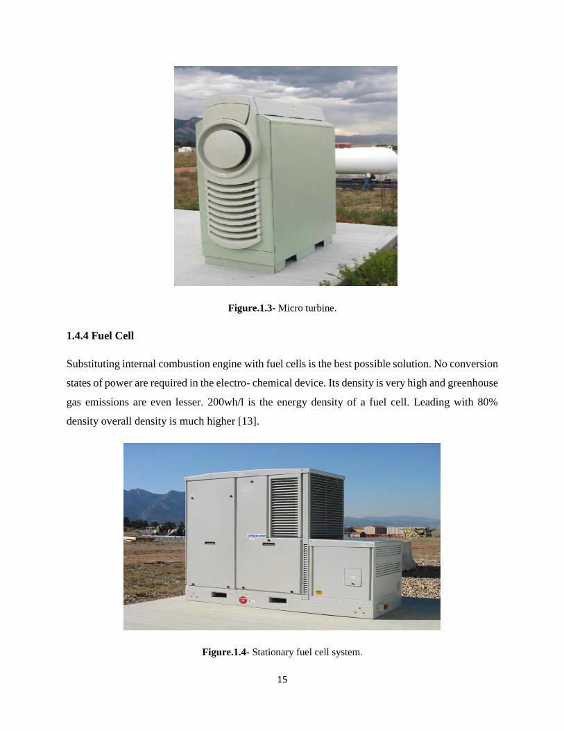
1.4.3 Micro turbines
Specially designed for helicopters and aircrafts, the micro turbines are made for electric application
of customer by making auxiliary power improvements in it. The power output given by a turbine
ranges from 30 kilowatt to 400 kilowatt .It has many features for e.g. it can be used in heating,
cooling, power system and in DG’s combined Though as a primary fuel micro turbines use natural
fuel but it can also use gasoline etc [17]. Advancement has been made till now and components
heat exchangers, inverters, communication, power electronics, control systems and
communication has been added. High speed generator is driven by 120,000 rpm spinning turbine
shaft. Efficiency of the micro turbines is nearly 30% by giving air back to the incoming air stream
from exhaust stream. For the elimination of oil and water, air bearings are being used for the air
cooling. It could be used for light loads industrial markets or some commercial buildings.
15
Figure.1.3- Micro turbine.
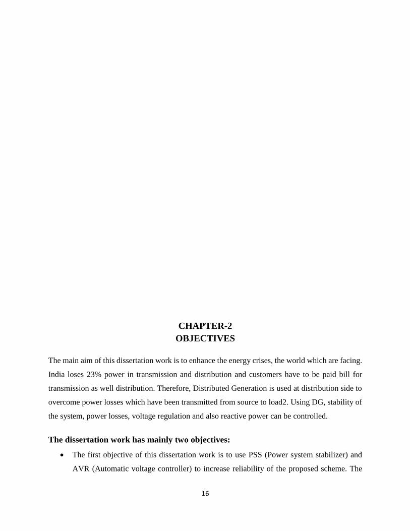
1.4.4 Fuel Cell
Substituting internal combustion engine with fuel cells is the best possible solution. No conversion
states of power are required in the electro- chemical device. Its density is very high and greenhouse
gas emissions are even lesser. 200wh/l is the energy density of a fuel cell. Leading with 80%
density overall density is much higher [13].
Figure.1.4- Stationary fuel cell system.
16
CHAPTER-2
OBJECTIVES
The main aim of this dissertation work is to enhance the energy crises, the world which are facing.
India loses 23% power in transmission and distribution and customers have to be paid bill for
transmission as well distribution. Therefore, Distributed Generation is used at distribution side to
overcome power losses which have been transmitted from source to load2. Using DG, stability of
the system, power losses, voltage regulation and also reactive power can be controlled.
The dissertation work has mainly two objectives:
The first objective of this dissertation work is to use PSS (Power system stabilizer) and
AVR (Automatic voltage controller) to increase reliability of the proposed scheme. The
17
purpose of PSS is to damp out rotor oscillations. AVR regulates the terminal voltage of the
generator. The modelling scheme could be utilized both for run-of –river scheme and for
storage scheme using optimum storage mechanism. The modelling is carried out with the
software MATLAB/Simulink 2015a.
Second objective of this dissertation work is to use STATCOM for compensating reactive
power to the synchronized system.
CHAPTER- 3
LITERATURE REVIEWS
H. Ashfaq et al., little scale hydro control era is turning into an alluring vitality elective for remote
ranges. They are for the most part keep running of-waterway sort which is coupled to settled speed
transformation frameworks while managing the water stream rate mechanically. A synchronous
generator based small scale hydro framework with diesel generator is created in this paper. To take
out every single mechanical change a power moulding framework (PCS) is proposed. Control
moulding framework contains a back-to back air conditioning/dc/air conditioning static converter
through which matrix association can be made. This proposed configuration is straightforward,
dependable, and effective. FFT examination is done and THD is broke down at load also, inverter.
18
Utilizing MATLAB Simulink based recreations topology and element execution of the proposed
framework is approved.
Lini Jacob, Divya S Nair, with expanding load request and an unnatural weather change, a
situation amicable kind of vitality answers for safeguard the earth for the future eras has turned
into an essential. Other than hydro control, numerous such vitality sources like wind and sunlight
based vitality is exceptionally potential sources to meet our vitality requests. Frameworks which
utilizes at least two renewable vitality sources is superior to anything the single source framework
as far as cost, productivity and unwavering quality. Standalone Wind/sun based cross breed era
framework offers a dependable and better answer for circulated era for remote regions and regions
where control from network is not accessible. Characteristic vitality based power era frameworks
are constantly furnished with capacity batteries to give steady yield regardless of the regular
vitality variety. There are odds of battery getting cheated. For the Standalone sort of era
establishment of dump load is important to keep the cheating by legitimate use of dump power.
End of dump load by including a Pumped Storage Hydroplant is pointed here. The plant won't just
disperse the abundance wind vitality additionally partakes in power era when requested for. The
demonstrating and reproduction is done utilizing MATLAB/SIMULINK programming.
Jayesh G. Priolkar, Suryanarayana Doolla, Advancement of force era by locally accessible
circulated era sources is one of the answers for present vitality emergency. This paper focusses on
combination of sunlight based photovoltaic, small hydro, diesel and battery vitality stockpiling
framework. Sources, for example, smaller than usual hydro and sun powered photovoltaic are
perfect, environment cordial and have capacity to supplement each other. The key aim of this work
is to mimic and examine the cross breed framework. The examination of proposed half breed
framework is conveyed out in Matlab/Simulink bundle. Control administration, control
furthermore, dependability viewpoints from points of view of execution are proposed and
approved by reproduction. In settling the framework, diesel motor generator, dump load and
battery are utilized as feasible means. Framework dissected incorporates blend of synchronous
furthermore, inverter based conveyed generators and mix of diverse sorts of burdens. Proposed
System is tried for shifting stack, era, unbalence, engine beginning and blame conditions. From
the recreation comes about it is found that Photovoltaic-Hydro- Battery vitality stockpiling
19
framework performs palatably under distinctive element conditions, keeping up voltage and
recurrence inside the cutoff points.
Ali Raza, Muhammad Saleem Mian, A complete model detailing and the latest control scheme
regarding MHPP (micro hydro power plant) that is grid connected is presented in this paper. In the
grid connection coupling is done between the synchronous generator, PCS (Power conditioning
system) and the hydraulic turbine which utilized run-of-river. In order to generate the best
outcomes from hydro resources, maximum power point tracker is incorporated with a hierarchical
structure which is multi-level. Grid includes the compensation of electric power, which is
independent of generation of active power. Simulations using MATLAB has been done that
validates varies control schemes and the models. For accuracy, set up of hydro power station is
employed for models.
Ayman Bakry Taha Attya1, Thomas Hartkopf, Wind ranches (WFs) commitment in recurrence
deviations abbreviation is a hazy area, particularly when WFs supplant huge customary era limits.
This review offers a calculation to incorporate hydro-pumped capacity station (HPSS) to give
inertial and essential support, amid recurrence drops by using put away wind vitality. Be that as it
may, wind turbines take after greatest power following, and don’t make a difference recurrence
bolster strategies, accordingly the squandered wind vitality is alleviated. To start with, HPSS
evaluated power and vitality limit are resolved in view of a few givens, including wind speed and
load attributes. In this manner, HPSS real angles are assessed [e.g. pump(s), store design and
generator(s)]. Second, offered calculation organizes vitality stockpiling, and discharging through
a few dynamic and static variables. HPSS yield is persistently controlled through a coordinated
way to deal with give recurrence bolster. A speculative framework is enlivened from Egyptian
lattice and genuine wind speed records at prescribed areas to have WFs. Contextual investigations
look at the calculation affect on recurrence recuperation, at 40% wind control entrance. The
reactions of warm era and HPSS are examined to highlight the impact of tuning the parameters of
the proposed calculation. The evaluation of a few recurrence measurements protects the positive
part of HPSS in recurrence drops abridgement. Reproduction situations are MATLAB and
Simulink.
Imad M. et al, This paper displays the outline of a MA TLAB test system of a half breed renewable
vitality framework connected for vitality era in country locales. The framework is recreated
20
utilizing MATLAB. It comprises of an arrangement of photovoltaic boards, a DFIG wind cultivate,
a pumped water stockpiling/era station and it is assigned to supply private/modern burdens. A
transmission line interfaces this framework to the principle control matrix. In spite of the fact that
customary models are utilized, the work inventiveness comprises of playing out an ideal control
of sources and loads so as to keep control adjusting amongst era and utilization in both associated
and islanded modes.
M. Vinatoru, E. Iancu, In hydro control plants from Romania, there is a significant enthusiasm
for the execution of advanced frameworks for observing and control supplanting the customary
control frameworks for power, recurrence and voltage. Along these lines is fundamental to create
scientific models able to precisely depict both dynamic and stationary conduct of the hydro units,
so as to have the capacity to actualize advanced control calculations. Additionally, it is important
to execute frameworks for checking and control of hydro power plants in a course framework
along a stream, all together enhance the utilization of the stream assets. This paper exhibits the
potential outcomes of demonstrating and simulation of the hydro control plants and plays out an
examination of various control structures and calculations.
Marcelo G. Molina1, Mario Pacas, A little scale hydropower station is typically a run-ofriver
plant that uses a settled speed drive with mechanical direction of the turbine water stream rate for
controlling the dynamic control era. This outline empowers to achieve high productivity over an
extensive variety of water streams however utilizing a complex working instrument, which is in
result costly and have a tendency to be more reasonable for extensive frameworks. This paper
proposes a propelled structure of a smaller scale hydro control plant (MHPP) based on a littler,
lighter, more hearty and more proficient higher-speed turbine. The recommended configuration is
much less complex and disposes of all mechanical modification through a novel proficient
electronic power moulding framework (PCS) for association with the electric network. In along
these lines, it permits acquiring higher unwavering quality and lower cost of the control plant.
Besides, a full definite model of the MHPP is inferred and a three-level control plan is planned,
including a full decoupled current control technique in the synchronous-pivoting d-q reference
outline. The dynamic execution of the proposed frameworks is completely approved by advanced
recreation did by utilizing Sim Power Systems of MATLAB/Simulink.
21
R. Ahshan et al, Miniaturized scale network framework is right now a theoretical answer for
satisfy the dedication of dependable power conveyance for future power frameworks. Renewable
power sources, for example, wind and hydro offer the best potential for emanation free power for
future miniaturized scale network frameworks. This paper shows a smaller scale network
framework in light of wind and hydro control sources and delivers issues identified with operation,
control, and solidness of the framework. The smaller scale lattice framework researched in this
paper speaks to a contextual investigation in Newfoundland, Canada. It comprises of a little hydro
era unit and a wind ranch that contains nine variable speed, twofold encouraged acceptance
generator based wind turbines. Utilizing Matlab/Simulink, the framework is demonstrated and
recreated to distinguish the specialized issues required in the operation of a miniaturized scale
matrix framework based on renewable power era units. The operational modes, specialized
challenges and a brief layout of reasonable ways to deal with tending to a portion of the specialized
issues are exhibited for further examination.
Issam Salhi et al, Hydropower is developing as a noteworthy donor to the world vitality
prerequisite. It’s boundless, clean and has numerous different advantages as it doesn’t experience
the issues of populace uprooting and ecological issues. Be that as it may, it requires control
frameworks to keep the recurrence values consistent. In this paper we build up a numerical model
for a miniaturized scale hydroelectric power plant (MHPP). We approve this model by
investigating a MHPP model’s exhibitions. The Prototype is introduced in our lab. We utilize the
downstream direction which guarantees great recurrence direction comes about. The utilized
controller is the “PI” one. The viable outcomes got are comparable for those in reproduction.
P. Hsu et al, Wind control plant (WPP) is regularly worked at solidarity control consider, and the
utility host where the WPP associated wants to direct the voltage. While this may not be an issue
in a solid matrix, the association with a feeble framework can be a dangerous. This paper
investigates the upsides of having voltage direction capacity by means of responsive power
control. Another issue in wind control era is that not all turbines can control its responsive power
because of specialized reason or legally binding commitments. A synchronous condenser (SC)
utilizing a changeless magnet synchronous generator (PMSG) is proposed for giving fundamental
responsive energy to directing voltage at a frail network association. A PMSG has the upside of
22
higher proficiency and unwavering quality. As a result of its absence of a field winding, a PMSG
is commonly controlled by a full-control converter, which can be exorbitant. In the proposed
framework, the responsive force of the SC is controlled by a serially associated compensator
working in a shut circle design. The compensator likewise damps the PMSG’s inclination to sway.
The compensator’s VA rating is just a small amount of the rating of the SC and the PMSG. In this
underlying examination, the proposed plan is appeared to be powerful by PC reenactments.
M. Vinatoru, E. Iancu, In hydro control plants from Romania, there is a real enthusiasm for the
usage of computerized frameworks for observing and control supplanting the routine control
frameworks for power, recurrence and voltage. Along these lines is vital to create scientific models
competent to precisely depict both dynamic and stationary conduct of the hydro units, with a
specific end goal to have the capacity to execute computerized control calculations. In addition, it
is important to execute frameworks for checking and control of hydro power plants in a course
framework along a waterway, all together improve the utilization of the waterway assets. This
paper displays the conceivable outcomes of displaying and reproduction of the hydro control plants
and plays out an investigation of various control structures and calculations.
Rinchin W. Mosobi, Sarsing Gao, The paper concentrates on probability of incorporating
distinctive renewable vitality sources (RES) and how the incorporated framework could be
adequately used to supply energy to remote and far-flung regions where matrix association is
testing and power request is ostensible. A point by point displaying of sunlight based photovoltaic
(SPV) framework, a wind vitality framework (WES) and a miniaturized scale hydro framework
(MHS) and their joining and possible association with a typical AC transport sustaining energy to
three-stage load is exhibited. Alongside greatest power point following (MPPT) framework, the
SPV framework has a DC-DC converter to get a managed DC yield. The voltage source inverter
(VSI) performs DC-AC change, the AC yield being smoothen by method for a LC channel. The
WES comprises of settled pitch edge and a variable speed wind turbine demonstrate which goes
about as prime mover to a capacitor energized non concurrent generator (CAG) implied for
creating the evaluated voltage. Additionally the MHS is displayed with a CAG accepting a steady
info control. The coordinated framework is demonstrated in Matlab simulink environment and the
reproduced results are introduced for various three-stage loads. The derivations are drawn and
sufficiently clarified.
23
Radharaman Shaha et al, Increasing expense of the fossil fuel have driven the accentuation on
the use of renewable vitality sources as an elective wellspring of era. More than 70% of the Indian
populace dwells in the towns which are denied of force for more than 6 to 12 hours a day. For the
general development of the economy, it is fundamental that the agro based economy too add to the
development. Lt is neither achievable nor temperate to transmit power in the distant districts where
a couple of families well in the town. Subsequently decentralized and conveyed era idea has come
up under the Rajiv Gandhi Gramin Vidyutikaran Yojana which is actualized by Rural Charge
Corporation. The Hybrid Renewable Energy Framework cannot just make ideal utilization of the
accessible renewable assets yet can get to be savvy by minimizing per unit cost of era which could
some way or another be high by considering any single source, for example, sun based, wind,
biomass or little hydro. MATLAB reproduction is finished by considering different suspicion
parameters for completing per unit cost of era.
Sachin Mishra et al, Hydropower, extensive and little, stays by a wide margin the most critical
of the renewable hotspots for electrical power era around the world, giving 19% of the planet’s
power. Little hydro is one of the practical and ecologically kind vitality advances to be considered
for country charge in less created nations. The establishment cost of the little hydropower venture
is primarily partitioned into two parts – Civil works and electromechanical gear. One of the most
essential component on the recuperation of a little hydro-control plant is the electromechanical
gear (turbine–alternator). The cost of the gear implies a high rate of the aggregate spending plan
of the plant. The present paper plans to build up a relationship to decide the cost in light of the
affecting parameters, for example, power and head. An endeavour has been made to build up the
pattern of the cost of electromechanical hardware with the expansion in leader of the hydropower
plant.
J.O. Jaber, Jordan‟s vitality adjust is to a great extent commanded by burnable fills. In any case,
the nation is plentifully supplied with sun oriented, wind and oil shale assets, notwithstanding
substantial and little scale hydropower ventures. In light of accessible information and the present
investigation, it is trusted that there are no less than 6-10 competitor destinations in the western
piece of Jordan and 2-3 areas in the eastern level, which could be created as little hydro plants,
with a consolidated capability of more than 33 MW. At present, just two locales, in particular King
Talal Dam and Aqaba Thermal Power Plant, have been created to be operational from 1980‟s. A
24
noteworthy hindrance to beginning little scale hydro control ventures is a comprehension of how
much the plan will cost. This paper gives likewise an outline of the mishaps that restrain the smooth
speculation and operation of little hydropower plants in Jordan. It is evaluated that introducing
little hydropower conspires on the most encouraging existing dams will create more than 200
GWh/year of electric vitality without affecting the regular habitat. Likewise, there are another few
locales, still under review, that might be produced later on as little hydro plants.
M. F. Elmorshedy et.al; [2015]: This paper present controlling procedure for an off grid WECS
using a permanent magnet synchronous generator (PMSG). In this initially, DC link voltage is
controlled by the duty cycle. Therefore, to convert the voltage of the DC link to the amplitude and
to the required frequency of the charging voltage, a sinusoidal pulse-width modulation (SPWM)
for controlling the inverter. The presented control strategy aims to regulate the load voltage in
terms of magnitude and frequency in different operating conditions, including wind speed. Wind
generation system under consideration he uses PMSG with a wind turbine, AC-DC, DC-DC and
DC-AC converter. The control strategy is presented based in part on control of the duty cycle,
Converter to convert the input variable to DC voltage, because to different operating conditions,
at a suitable constant DC voltage. Therefore, a modulated sinusoidal pulse width (SPWM) UPS is
used to adjust the amplitude and frequency by controlling the modulation index. A sample
simulation results are obtained and analyzed here. [3]
Chih-Chiang Hua et.al; [2013]: The proposed system consists of a wind generator, a boost
converter, and a full-bridge inverter. In this system, a digital signal processor is used to be the
system controller. Wind energy is a natural energy available for use, and will not be depleted due
to the development of the human. The use of wind energy can be divided into two types, one is
mediated by wind energy converted into kinetic energy, such as a windmill, sailing; another one
is converted into electrical energy, namely wind power. [7]
Sarkut Ibrahim et.al; [2013]: This paper presents analysis and improvement of power quality
(voltage sag, and harmonics) performance of smart grid connected inverter used in distributed
generation.The structure of the designed controller consists of outer power with harmonic control
loop, middle voltage control loop and inner current control power loop for real and reactive power
control in dq reference frame.The developed controller controls the real and Converter). [8]
25
CHAPTER- 4
RENEWABLE ENERGY SORUCES
4.1 Hydro power plant
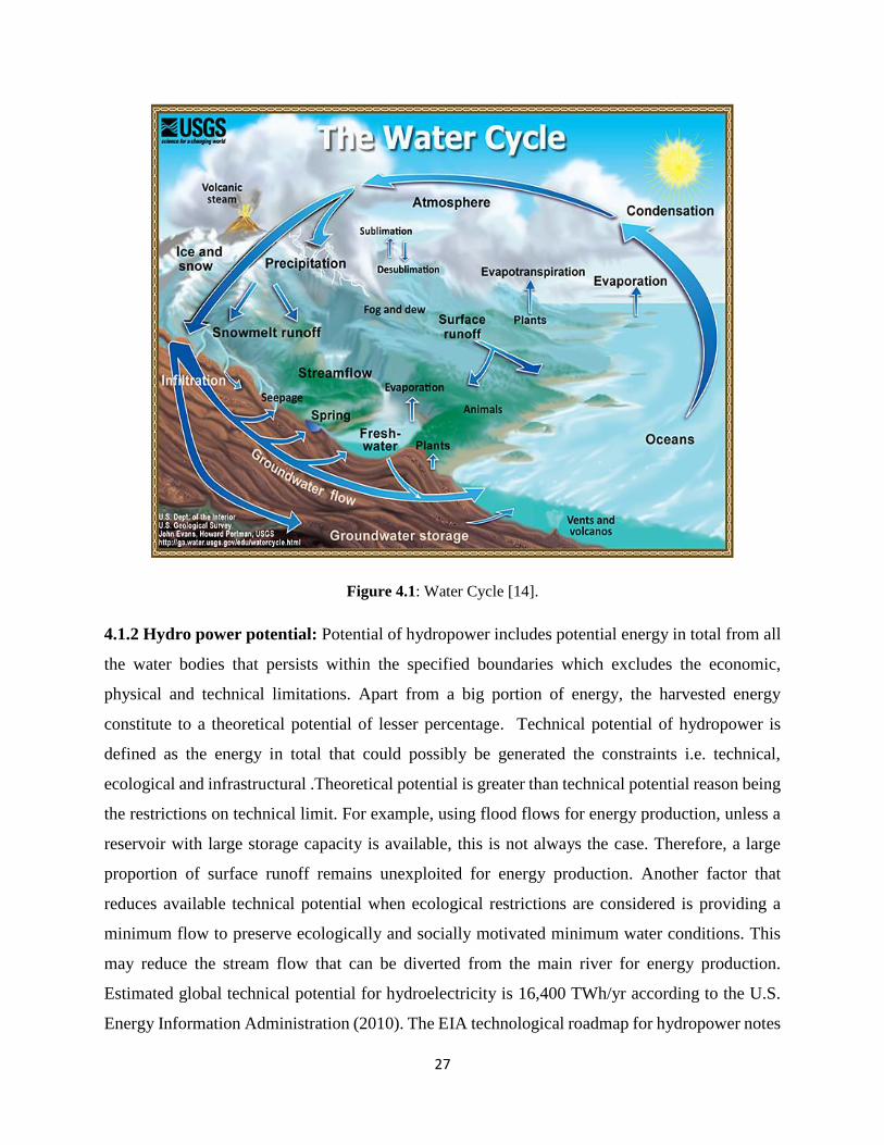
4.1.1 Development of hydro power: Since hydrologic cycle is derived by the solar energy, thus
Hydropower is a renewable form of energy. The process that undergo in hydrological cycle is;
Water from the water bodies is heated by the sun for about 97%.Evaporation of water takes place.
Upper atmosphere gets the water vapours by air currents that aroused where the formation of
26
vapour to the cloud occurs when the vapours are condensed by the low temperatures .The process
of precipitation of water occurs when clouds are moved by air currents .Much higher altitudes than
sea levels can be achieved through this process.
Water energy harness takes place when water descends from higher elevations due to gravity.
Energy fetching takes place in the form of kinetic energy which comes from flowing water and
gravitational energy when the water falls. The availability of kinetic energy depends upon water
dropping level, volume/time of water or discharge, slope angel
Turbines harness the energy possessed by the flowing water .Turbines are placed in between the
flowing water. Turbine runner is rotated by the force of the moving water that is exerted over the
blades of turbine. [14, 15].
Ancient times endeavour the practice of Harness of water mechanical energy. Uses of it earlier
included grinding grain, manufacturing textiles, sawing wood, irrigation etc. water wheels converts
the energy of water current into useful power. In 3rd century BC water wheel was invented. For
the improvement in efficiencies hydro turbines bought a revolution in industries which replaces
the waterwheels since more than a diameter, head could be exploited by it. Since 19th century
hydropower has been used for electricity, which perhaps makes it the first renewable source of
energy. In today’s era it’s still the very common source of generating electricity in renewable form
worldwide.
27
Figure 4.1: Water Cycle [14].
4.1.2 Hydro power potential: Potential of hydropower includes potential energy in total from all
the water bodies that persists within the specified boundaries which excludes the economic,
physical and technical limitations. Apart from a big portion of energy, the harvested energy
constitute to a theoretical potential of lesser percentage. Technical potential of hydropower is
defined as the energy in total that could possibly be generated the constraints i.e. technical,
ecological and infrastructural .Theoretical potential is greater than technical potential reason being
the restrictions on technical limit. For example, using flood flows for energy production, unless a
reservoir with large storage capacity is available, this is not always the case. Therefore, a large
proportion of surface runoff remains unexploited for energy production. Another factor that
reduces available technical potential when ecological restrictions are considered is providing a
minimum flow to preserve ecologically and socially motivated minimum water conditions. This
may reduce the stream flow that can be diverted from the main river for energy production.
Estimated global technical potential for hydroelectricity is 16,400 TWh/yr according to the U.S.
Energy Information Administration (2010). The EIA technological roadmap for hydropower notes
28
that technical potential corresponds to about 35 percent of theoretical potential [16]. Hydropower’s
economic potential is defined as the energy capacity that is economically exploitable relative to
alternative energy forms. Current hydropower production and unexploited resources for the
regions of the world and for the five countries with the highest technical potential are shown in
Figure 3-2 below. Asia has by far the largest hydropower technical potential, followed by Latin
America and North America. China has the highest existing energy generation and uses 24 percent
of its potential. Further information on hydropower potential types can be found in H. B.
Horlacher, 2003, Globale Potenziale der Wasserkraft [17].
Advantages: In the comparison with other renewable source of energy, the major benefits of hydro
plant are as follows-
1. Technology used for hydro plant is indeed reliable and proven. The technology is century old
and rehabilitation of plant is much trouble-free which could be upgraded easily to the
advancements taken place so far in hydro technology.
2. Hydropower usage depends upon domestic water resources therefore the there is a stability in
price irrespective if fluctuations taking place in market. There is flexibility in the operation of
hydro plant due to the various schemes for the storage in hydro plants for e.g. pumped storage and
dams since it could be shut down or ramped out according to the necessity. This leads to the better
reliability of power continuity.
At the time of variation in the electricity demands. So, its utility is quite high to meet the peak
demands with its storage and to supply power to other plants which are present in the same grid
(wind and solar) that often has to go through power output fluctuations.
3. The generation of electricity is renewable in nature of hydro plant since these is no fuel
requirement and water level doesn’t goes down which is being used.
4. Mostly, hydropower as a renewable source of energy is also highly economically competitive.
In case of upgrading or rehabilitation of hydro plant that already exists, there are schemes that
provide cost- effective opportunities to increase capacity.
5. For irrigation or drinking purpose, water is stored in the reservoirs which are manmade. It also
make human less vulnerable to drought. Other purpose of reservoirs is that it improves the capacity
of waterway transport. It also provides protection from flood. During the water scarcity, the
reservoir in HPPs helps in the generation of electricity that regulate the fluctuations.
29
6. The impacts of environment those are triggered by hydropower schemes implementation are
manageable and very well known.
Disadvantages: Hydropower disadvantages includes;
1. Cost of up-front investment is high in comparison to other technologies for eg. thermal plant
with advantage of much lower cost of operation.
2. The river damages the fauna and flora, the reservoirs build up often destroy the inundated area
i.e. the area it covers, the uses of the river are hampered for e.g. it could be used for the purpose
of navigation. Though the designing of the project of power plant could possibly eliminate many
of the negative impacts. Institutions like multilateral financial institution and IFC consist of many
strict requirements which are mandatory for mitigation and assessment of environmental and social
impacts.
4.1.3 Classification of hydro plant by size: HPP is distinguishes by its size and the standards has
been accepted widely in countries.
a) MICRO: It lies in installed capacity less than 0.1MW
HPP of this type can supply the energy to the remote community of smaller size or an isolated
industry. It’s of stand- alone type usually i.e. it is not grid connected and mostly connected with
run- of- river. To guarantee the continuity of electricity per day for some minimum period, tanks
of small storage are constructed. So the continuity of electrical supply remains intact in condition
persisting low flow of water. Micro HPP is usually placed in remote rural areas of countries that
are still developing where without dependency on fuel economical source of energy is provided.
b) SMALL: It lies between 0.1MW< Installed Capacity <10 MW. Possibly the maximum limit
could set upto35 MW in some countries. Low discharge is exploiting by small HPPs. These HPPs
are usually connected to the power grid and are of run-of river type.
c) MEDIUM: It lies between 10MW< installed capacity <100MW. These HPPs are connected to
the grid mostly and are storage and run-of type both. The similarities of equipment like E and M
are same as large power HPPs schemes.
30
d) LARGE: It lies between installed capacities greater than 100MW. These types of HPPs
schemes are grid connected. It can both be of storage or run- of –river type. It can serve a large
locality conditions and needs.
4.1.4 Classification according to head: In accordance to below scheme HPP has been divided in
relevance to its head size being used for the production of electricity.
a. High head: The head should be greater than 100m
b. Medium head: Head should lie between 30m to 100m
c. Low head: Head should be greater than 30m
4.1.5 Classification by operation:
4.1.5.1 Storage scheme: The dam structure water impoundment which is created upstream which
acts like a reservoir where during the flow of high periods, water stored. Therefore in the times of
fluctuations due to seasonal variations and dry weather, the water that is stored in the reservoir
generates energy by inflowing. Flow regulation level is determined by reservoir size.
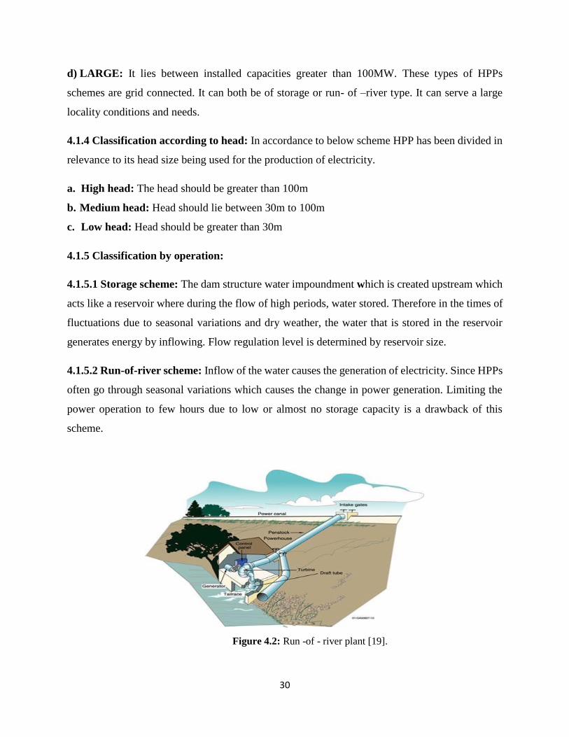
4.1.5.2 Run-of-river scheme: Inflow of the water causes the generation of electricity. Since HPPs
often go through seasonal variations which causes the change in power generation. Limiting the
power operation to few hours due to low or almost no storage capacity is a drawback of this
scheme.
Figure 4.2: Run -of - river plant [19].
31
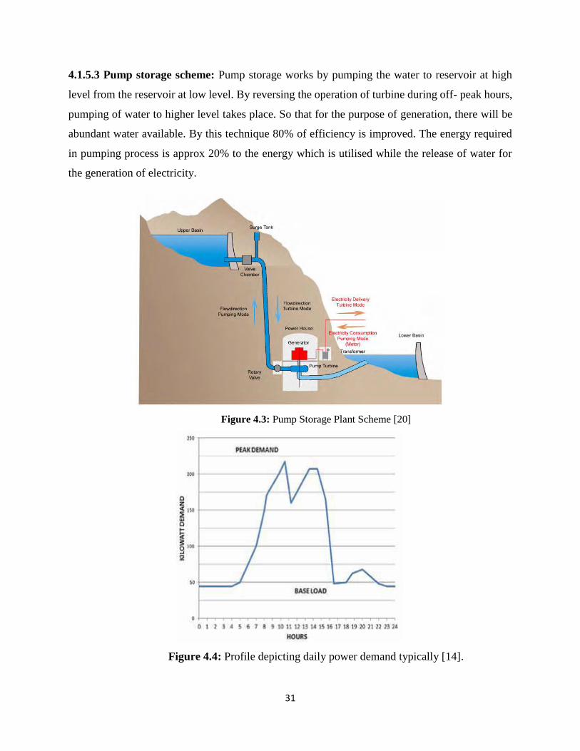
4.1.5.3 Pump storage scheme: Pump storage works by pumping the water to reservoir at high
level from the reservoir at low level. By reversing the operation of turbine during off- peak hours,
pumping of water to higher level takes place. So that for the purpose of generation, there will be
abundant water available. By this technique 80% of efficiency is improved. The energy required
in pumping process is approx 20% to the energy which is utilised while the release of water for
the generation of electricity.
Figure 4.3: Pump Storage Plant Scheme [20]
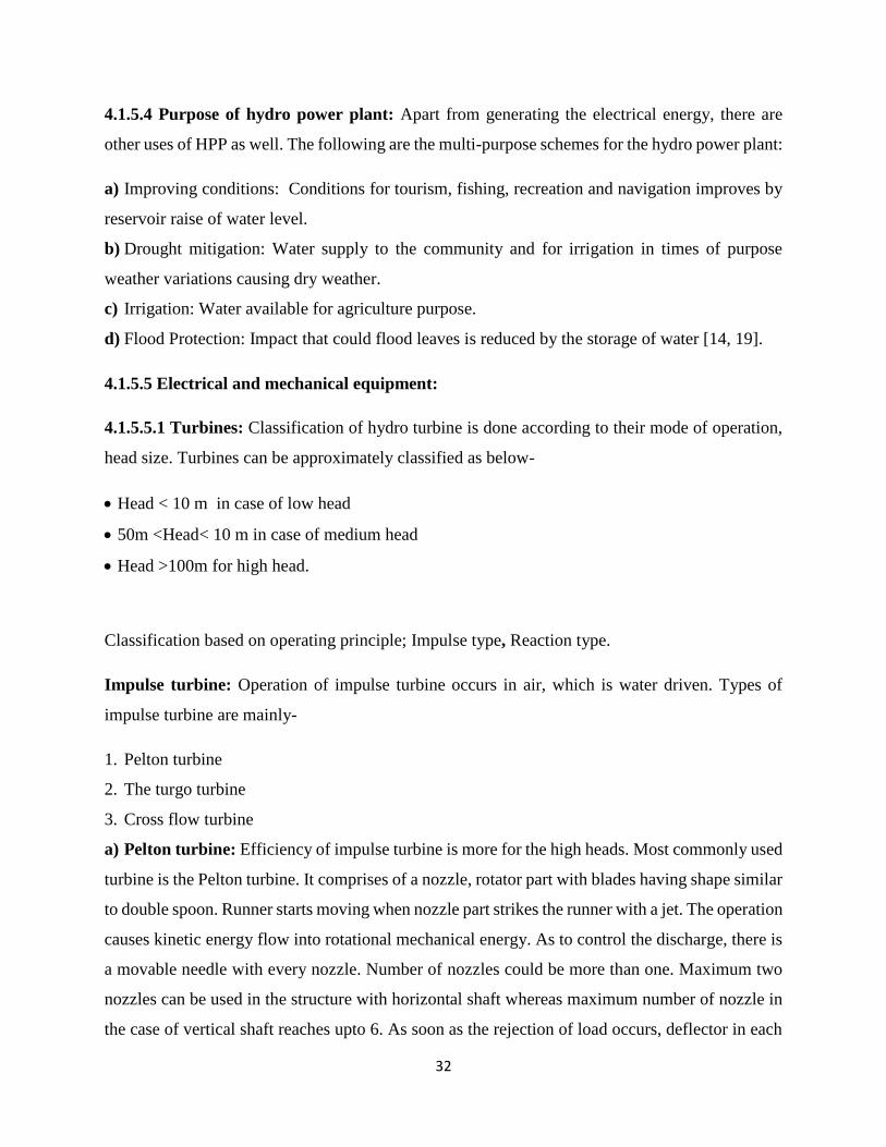
Figure 4.4: Profile depicting daily power demand typically [14].
32
4.1.5.4 Purpose of hydro power plant: Apart from generating the electrical energy, there are
other uses of HPP as well. The following are the multi-purpose schemes for the hydro power plant:
a) Improving conditions: Conditions for tourism, fishing, recreation and navigation improves by
reservoir raise of water level.
b) Drought mitigation: Water supply to the community and for irrigation in times of purpose
weather variations causing dry weather.
c) Irrigation: Water available for agriculture purpose.
d) Flood Protection: Impact that could flood leaves is reduced by the storage of water [14, 19].
4.1.5.5 Electrical and mechanical equipment:
4.1.5.5.1 Turbines: Classification of hydro turbine is done according to their mode of operation,
head size. Turbines can be approximately classified as below-
Head < 10 m in case of low head
50m <Head< 10 m in case of medium head
Head >100m for high head.
Classification based on operating principle; Impulse type, Reaction type.
Impulse turbine: Operation of impulse turbine occurs in air, which is water driven. Types of
impulse turbine are mainly-
1. Pelton turbine
2. The turgo turbine
3. Cross flow turbine
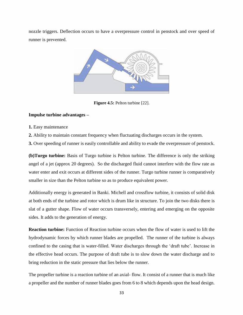
a) Pelton turbine: Efficiency of impulse turbine is more for the high heads. Most commonly used
turbine is the Pelton turbine. It comprises of a nozzle, rotator part with blades having shape similar
to double spoon. Runner starts moving when nozzle part strikes the runner with a jet. The operation
causes kinetic energy flow into rotational mechanical energy. As to control the discharge, there is
a movable needle with every nozzle. Number of nozzles could be more than one. Maximum two
nozzles can be used in the structure with horizontal shaft whereas maximum number of nozzle in
the case of vertical shaft reaches upto 6. As soon as the rejection of load occurs, deflector in each
33
nozzle triggers. Deflection occurs to have a overpressure control in penstock and over speed of
runner is prevented.
Figure 4.5: Pelton turbine [22].
Impulse turbine advantages –
1. Easy maintenance
2. Ability to maintain constant frequency when fluctuating discharges occurs in the system.
3. Over speeding of runner is easily controllable and ability to evade the overpressure of penstock.
(b)Turgo turbine: Basis of Turgo turbine is Pelton turbine. The difference is only the striking
angel of a jet (approx 20 degrees). So the discharged fluid cannot interfere with the flow rate as
water enter and exit occurs at different sides of the runner. Turgo turbine runner is comparatively
smaller in size than the Pelton turbine so as to produce equivalent power.
Additionally energy is generated in Banki. Michell and crossflow turbine, it consists of solid disk
at both ends of the turbine and rotor which is drum like in structure. To join the two disks there is
slat of a gutter shape. Flow of water occurs transversely, entering and emerging on the opposite
sides. It adds to the generation of energy.
Reaction turbine: Function of Reaction turbine occurs when the flow of water is used to lift the
hydrodynamic forces by which runner blades are propelled. The runner of the turbine is always
confined to the casing that is water-filled. Water discharges through the ‘draft tube’. Increase in
the effective head occurs. The purpose of draft tube is to slow down the water discharge and to
bring reduction in the static pressure that lies below the runner.
The propeller turbine is a reaction turbine of an axial- flow. It consist of a runner that is much like
a propeller and the number of runner blades goes from 6 to 8 which depends upon the head design.
34
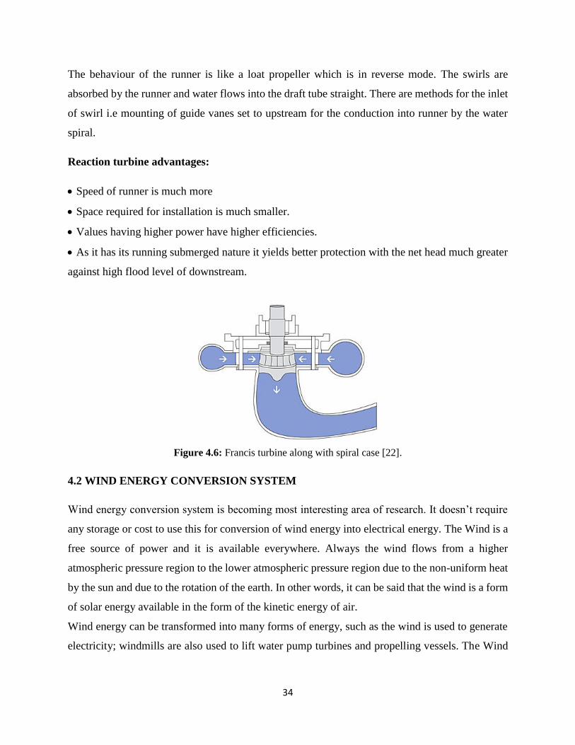
The behaviour of the runner is like a loat propeller which is in reverse mode. The swirls are
absorbed by the runner and water flows into the draft tube straight. There are methods for the inlet
of swirl i.e mounting of guide vanes set to upstream for the conduction into runner by the water
spiral.
Reaction turbine advantages:
Speed of runner is much more
Space required for installation is much smaller.
Values having higher power have higher efficiencies.
As it has its running submerged nature it yields better protection with the net head much greater
against high flood level of downstream.
Figure 4.6: Francis turbine along with spiral case [22].
4.2 WIND ENERGY CONVERSION SYSTEM
Wind energy conversion system is becoming most interesting area of research. It doesn’t require
any storage or cost to use this for conversion of wind energy into electrical energy. The Wind is a
free source of power and it is available everywhere. Always the wind flows from a higher
atmospheric pressure region to the lower atmospheric pressure region due to the non-uniform heat
by the sun and due to the rotation of the earth. In other words, it can be said that the wind is a form
of solar energy available in the form of the kinetic energy of air.
Wind energy can be transformed into many forms of energy, such as the wind is used to generate
electricity; windmills are also used to lift water pump turbines and propelling vessels. The Wind
35
have a good amount of energy in it and whatever amount of power obtained from the wind is much
greater than the power available from other sources which are used by humans.
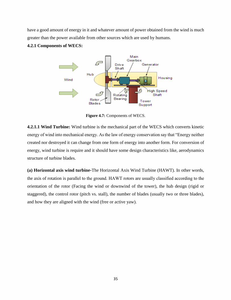
4.2.1 Components of WECS:
Figure 4.7: Components of WECS.
4.2.1.1 Wind Turbine: Wind turbine is the mechanical part of the WECS which converts kinetic
energy of wind into mechanical energy. As the law of energy conservation say that “Energy neither
created nor destroyed it can change from one form of energy into another form. For conversion of
energy, wind turbine is require and it should have some design characteristics like, aerodynamics
structure of turbine blades.
(a) Horizontal axis wind turbine-The Horizontal Axis Wind Turbine (HAWT). In other words,
the axis of rotation is parallel to the ground. HAWT rotors are usually classified aссording to the
orientation of the rotor (Facing the wind or downwind of the tower), the hub design (rigid or
staggered), the control rotor (pitch vs. stall), the number of blades (usually two or three blades),
and how they are aligned with the wind (free or active yaw).
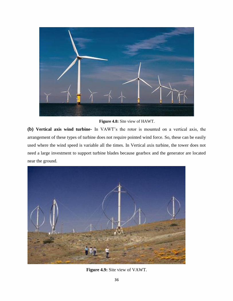
36
Figure 4.8: Site view of HAWT.
(b) Vertical axis wind turbine- In VAWT’s the rotor is mounted on a vertical axis, the
arrangement of these types of turbine does not require pointed wind force. So, these can be easily
used where the wind speed is variable all the times. In Vertical axis turbine, the tower does not
need a large investment to support turbine blades because gearbox and the generator are located
near the ground.
Figure 4.9: Site view of VAWT.
37
There are some basic things on which basis state of WECS s define and output is controlled as
well which are;
(a) Yaw control: It is essentially the means of orienting the wind turbine, as it turns in the direction
of the wind. If we use Yaw as control mechanism then we have to make it all the time move.
(b) Solidity: Solidity is defined as the ratio of the projected blade area to the area of the wind
intercepted. The projected blade area is equal to the area projected in the direction of the wind.
With torque and speed solidity has a direct relationship. High solidity rotors are suitable for
pumping water because it has high torque and low speed. Low solidity rotors are suitable for
electrical power generation because it has high-speed and low torque.
(c) Tip Speed Ratio: TSR of a wind turbine can be express that
λ= (wt*r)/vw
where;
λ= Non-dimensional
wt= Rotational Speed of turbine
r= Radius of turbine
vw= Wind Speed (m/s)
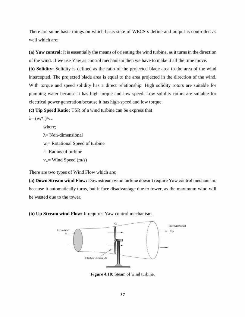
There are two types of Wind Flow which are;
(a) Down Stream wind Flow: Downstream wind turbine doesn’t require Yaw control mechanism,
because it automatically turns, but it face disadvantage due to tower, as the maximum wind will
be wasted due to the tower.
(b) Up Stream wind Flow: It requires Yaw control mechanism.
Figure 4.10: Steam of wind turbine.
38
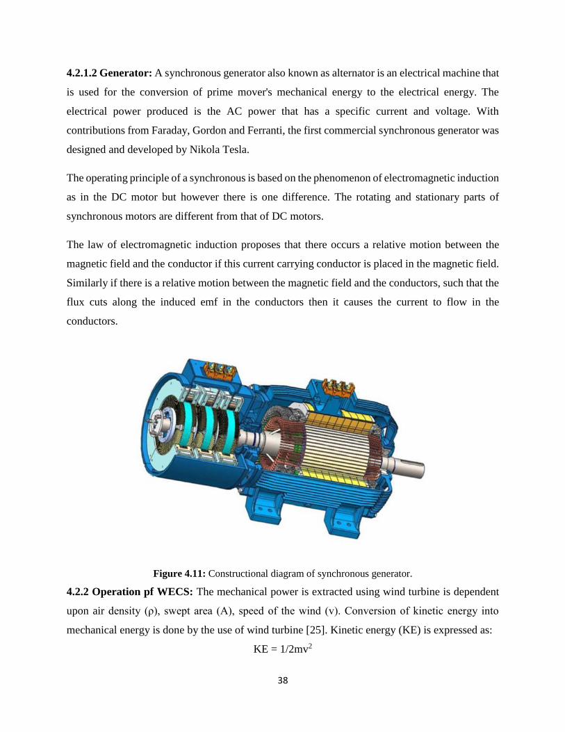
4.2.1.2 Generator: A synchronous generator also known as alternator is an electrical machine that
is used for the conversion of prime mover's mechanical energy to the electrical energy. The
electrical power produced is the AC power that has a specific current and voltage. With
contributions from Faraday, Gordon and Ferranti, the first commercial synchronous generator was
designed and developed by Nikola Tesla.
The operating principle of a synchronous is based on the phenomenon of electromagnetic induction
as in the DC motor but however there is one difference. The rotating and stationary parts of
synchronous motors are different from that of DC motors.
The law of electromagnetic induction proposes that there occurs a relative motion between the
magnetic field and the conductor if this current carrying conductor is placed in the magnetic field.
Similarly if there is a relative motion between the magnetic field and the conductors, such that the
flux cuts along the induced emf in the conductors then it causes the current to flow in the
conductors.
Figure 4.11: Constructional diagram of synchronous generator.
4.2.2 Operation pf WECS: The mechanical power is extracted using wind turbine is dependent
upon air density (ρ), swept area (A), speed of the wind (v). Conversion of kinetic energy into
mechanical energy is done by the use of wind turbine [25]. Kinetic energy (KE) is expressed as:
KE = 1/2mv2
39
where,
m is mass of air in kg
v is speed of wind in m/s
Since power is defined as the rate of change of energy, therefore,
P = dE/dt
P= 1
2𝑣2 𝑑𝑚
𝑑𝑡 …………. (4.1)
Since mass flow rate is,
𝑑𝑚
𝑑𝑡 = ρA
𝑑𝑥
𝑑𝑡
𝑑𝑚
𝑑𝑡 = ρAv
Where, v = 𝑑𝑥
𝑑𝑡
From equation (4.1)
P = 1
2 ρA𝑣3
Ρ = air density in kg/m3
A = swept area of turbine blades in m2
It can be seen from above equation that mechanical power of wind turbine directly proportional
cube of wind speed. Every wind turbine have their betz limit (approximately 59%) which ensure
that how much energy can be extracted from wind. Turbine can never extract whole kinetic energy
present in wind and if it can then there will be no downwind behind the rotor. Figure shows the
area covered by upwind and downwind are different. Therefore, upwind speed will be higher in
comparison to the downwind wind speed.
40
4.3 Power System Stabilizer (PSS):
Basically power system stabilizer is applied at the generation side with generator to damp out the
rotor oscillation. Rotor oscillation takes place into the system due to loss of excitation, sudden loss
of load, unit generation failure, failure of synchronization and faults near generator [34].
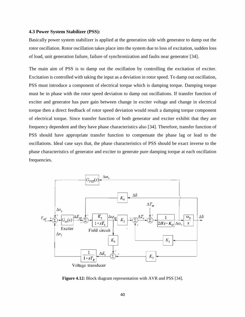
The main aim of PSS is to damp out the oscillation by controlling the excitation of exciter.
Excitation is controlled with taking the input as a deviation in rotor speed. To damp out oscillation,
PSS must introduce a component of electrical torque which is damping torque. Damping torque
must be in phase with the rotor speed deviation to damp out oscillations. If transfer function of
exciter and generator has pure gain between change in exciter voltage and change in electrical
torque then a direct feedback of rotor speed deviation would result a damping torque component
of electrical torque. Since transfer function of both generator and exciter exhibit that they are
frequency dependent and they have phase characteristics also [34]. Therefore, transfer function of
PSS should have appropriate transfer function to compensate the phase lag or lead to the
oscillations. Ideal case says that, the phase characteristics of PSS should be exact inverse to the
phase characteristics of generator and exciter to generate pure damping torque at each oscillation
frequencies.
Figure 4.12: Block diagram representation with AVR and PSS [34].
41
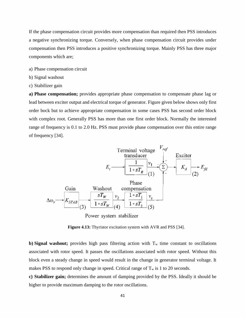
If the phase compensation circuit provides more compensation than required then PSS introduces
a negative synchronizing torque. Conversely, when phase compensation circuit provides under
compensation then PSS introduces a positive synchronizing torque. Mainly PSS has three major
components which are;
a) Phase compensation circuit
b) Signal washout
c) Stabilizer gain
a) Phase compensation; provides appropriate phase compensation to compensate phase lag or
lead between exciter output and electrical torque of generator. Figure given below shows only first
order bock but to achieve appropriate compensation in some cases PSS has second order block
with complex root. Generally PSS has more than one first order block. Normally the interested
range of frequency is 0.1 to 2.0 Hz. PSS must provide phase compensation over this entire range
of frequency [34].
Figure 4.13: Thyristor excitation system with AVR and PSS [34].
b) Signal washout; provides high pass filtering action with Tw time constant to oscillations
associated with rotor speed. It passes the oscillations associated with rotor speed. Without this
block even a steady change in speed would result in the change in generator terminal voltage. It
makes PSS to respond only change in speed. Critical range of Tw is 1 to 20 seconds.
c) Stabilizer gain; determines the amount of damping provided by the PSS. Ideally it should be
higher to provide maximum damping to the rotor oscillations.
42
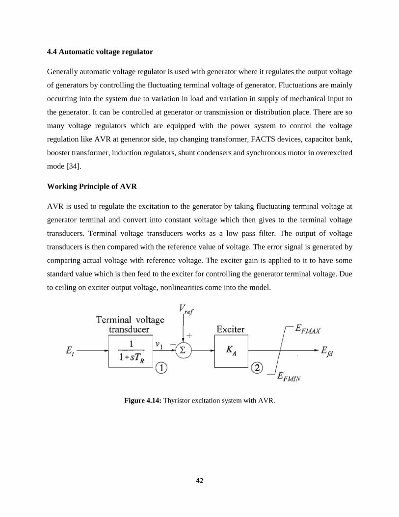
4.4 Automatic voltage regulator
Generally automatic voltage regulator is used with generator where it regulates the output voltage
of generators by controlling the fluctuating terminal voltage of generator. Fluctuations are mainly
occurring into the system due to variation in load and variation in supply of mechanical input to
the generator. It can be controlled at generator or transmission or distribution place. There are so
many voltage regulators which are equipped with the power system to control the voltage
regulation like AVR at generator side, tap changing transformer, FACTS devices, capacitor bank,
booster transformer, induction regulators, shunt condensers and synchronous motor in overexcited
mode [34].
Working Principle of AVR
AVR is used to regulate the excitation to the generator by taking fluctuating terminal voltage at
generator terminal and convert into constant voltage which then gives to the terminal voltage
transducers. Terminal voltage transducers works as a low pass filter. The output of voltage
transducers is then compared with the reference value of voltage. The error signal is generated by
comparing actual voltage with reference voltage. The exciter gain is applied to it to have some
standard value which is then feed to the exciter for controlling the generator terminal voltage. Due
to ceiling on exciter output voltage, nonlinearities come into the model.
Figure 4.14: Thyristor excitation system with AVR.
43
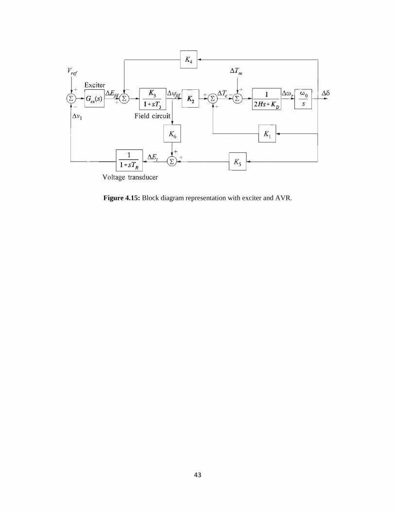
Figure 4.15: Block diagram representation with exciter and AVR.
44
CHAPTER-5
RESEARCH METHODOLGY
Various research papers have issues on transmission and distribution published by IEEE. Papers
are dealt about the tremendous wastage of power in the transmission system and the issues related
voltage at receiving end. Paper shows how, if integration of distributed generation into the
distribution network can eliminate the issues being faced at the receiving end. In this dissertation
work DG is used to improve the power quality and voltage stability for its numerous advantages.
The dissertation work shows how to keep DG’s safe in time of faults in the line from grid.
Simulation model of DG is shown with the power grid and distribution end using MATLAB.
45
CHAPTER-6
SYSTEM DESCRIPTION AND SIMULATION RESULTS
6.1 System Description
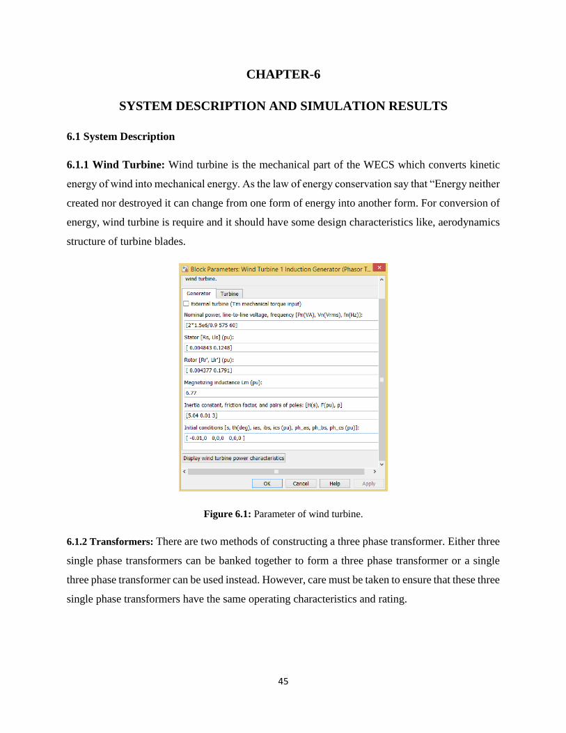
6.1.1 Wind Turbine: Wind turbine is the mechanical part of the WECS which converts kinetic
energy of wind into mechanical energy. As the law of energy conservation say that “Energy neither
created nor destroyed it can change from one form of energy into another form. For conversion of
energy, wind turbine is require and it should have some design characteristics like, aerodynamics
structure of turbine blades.
Figure 6.1: Parameter of wind turbine.
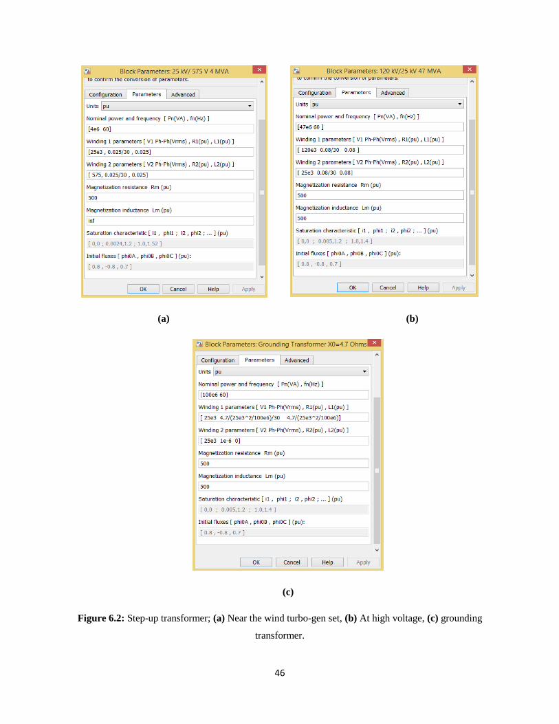
6.1.2 Transformers: There are two methods of constructing a three phase transformer. Either three
single phase transformers can be banked together to form a three phase transformer or a single
three phase transformer can be used instead. However, care must be taken to ensure that these three
single phase transformers have the same operating characteristics and rating.
46
(a) (b)
(c)
Figure 6.2: Step-up transformer; (a) Near the wind turbo-gen set, (b) At high voltage, (c) grounding
transformer.
47
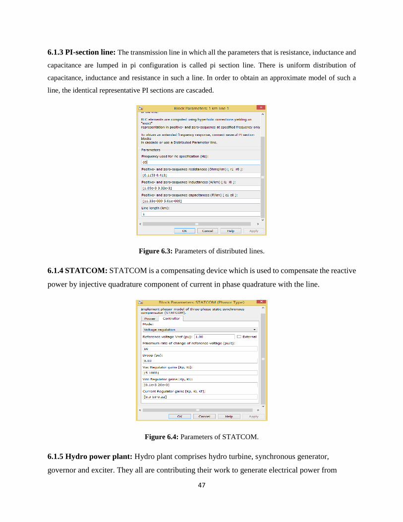
6.1.3 PI-section line: The transmission line in which all the parameters that is resistance, inductance and
capacitance are lumped in pi configuration is called pi section line. There is uniform distribution of
capacitance, inductance and resistance in such a line. In order to obtain an approximate model of such a
line, the identical representative PI sections are cascaded.
Figure 6.3: Parameters of distributed lines.
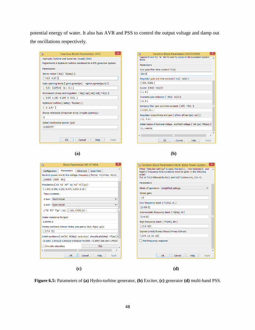
6.1.4 STATCOM: STATCOM is a compensating device which is used to compensate the reactive
power by injective quadrature component of current in phase quadrature with the line.
Figure 6.4: Parameters of STATCOM.
6.1.5 Hydro power plant: Hydro plant comprises hydro turbine, synchronous generator,
governor and exciter. They all are contributing their work to generate electrical power from
48
potential energy of water. It also has AVR and PSS to control the output voltage and damp out
the oscillations respectively.
(a) (b)
(c) (d)
Figure 6.5: Parameters of (a) Hydro-turbine generator, (b) Exciter, (c) generator (d) multi-band PSS.
49
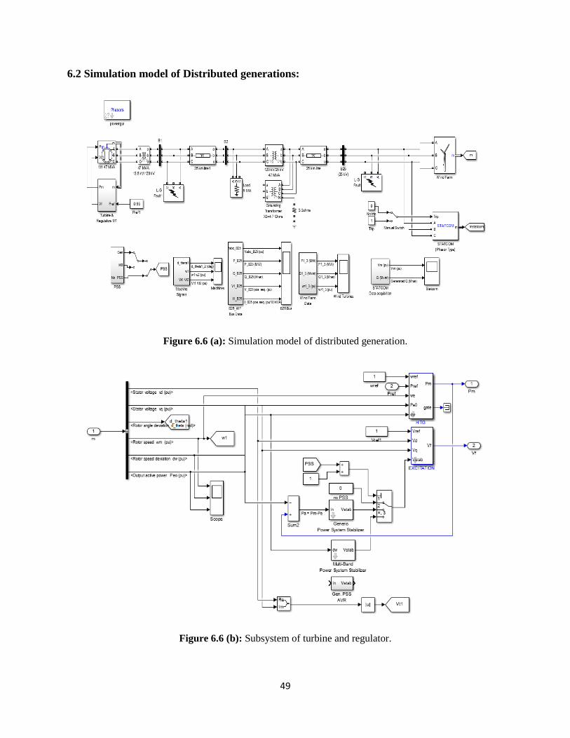
6.2 Simulation model of Distributed generations:
Figure 6.6 (a): Simulation model of distributed generation.
Figure 6.6 (b): Subsystem of turbine and regulator.
50
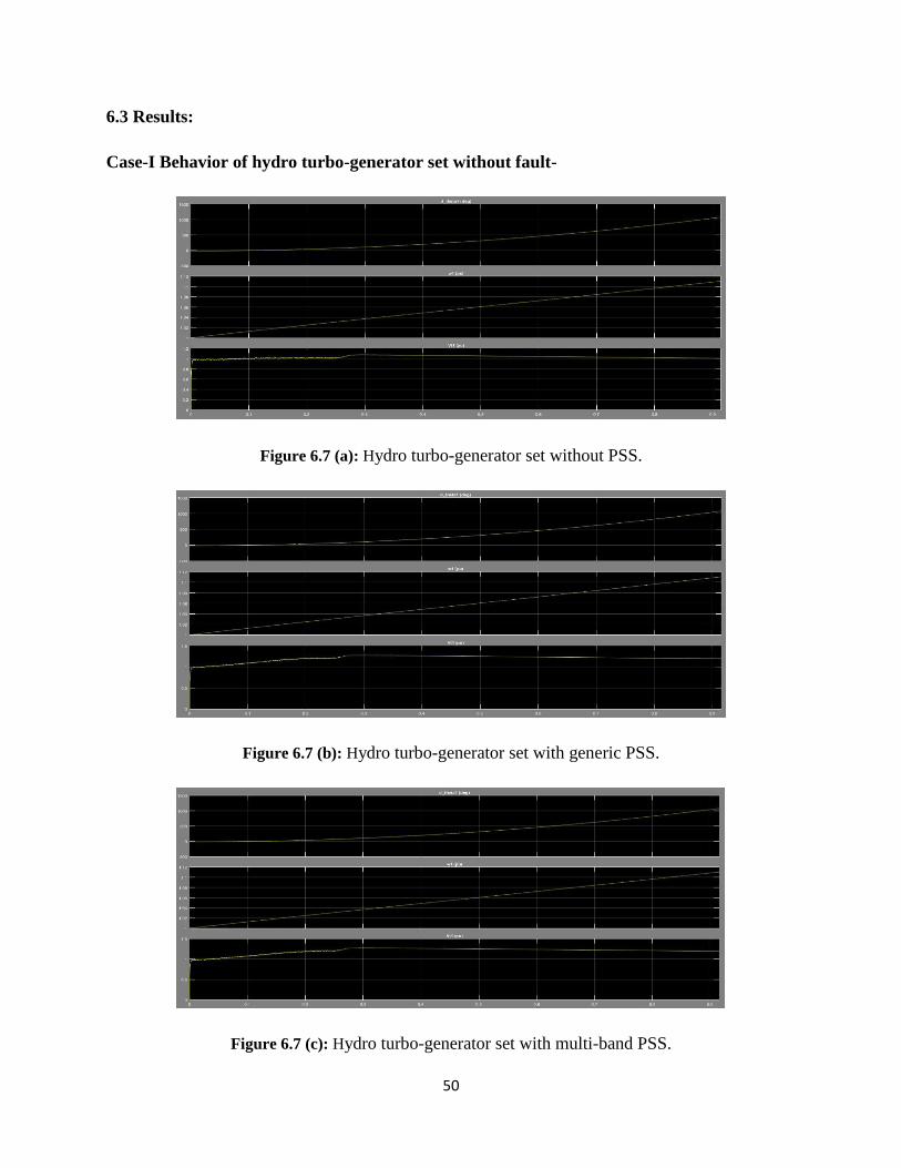
6.3 Results:
Case-I Behavior of hydro turbo-generator set without fault-
Figure 6.7 (a): Hydro turbo-generator set without PSS.
Figure 6.7 (b): Hydro turbo-generator set with generic PSS.
Figure 6.7 (c): Hydro turbo-generator set with multi-band PSS.
51
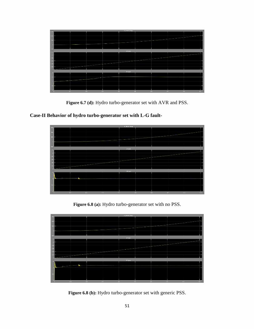
Figure 6.7 (d): Hydro turbo-generator set with AVR and PSS.
Case-II Behavior of hydro turbo-generator set with L-G fault-
Figure 6.8 (a): Hydro turbo-generator set with no PSS.
Figure 6.8 (b): Hydro turbo-generator set with generic PSS.
52
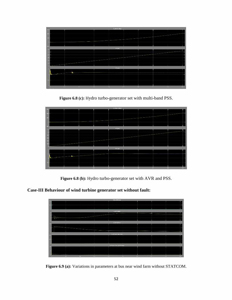
Figure 6.8 (c): Hydro turbo-generator set with multi-band PSS.
Figure 6.8 (b): Hydro turbo-generator set with AVR and PSS.
Case-III Behaviour of wind turbine generator set without fault:
Figure 6.9 (a): Variations in parameters at bus near wind farm without STATCOM.
53
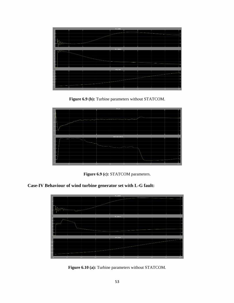
Figure 6.9 (b): Turbine parameters without STATCOM.
Figure 6.9 (c): STATCOM parameters.
Case-IV Behaviour of wind turbine generator set with L-G fault:
Figure 6.10 (a): Turbine parameters without STATCOM.
54
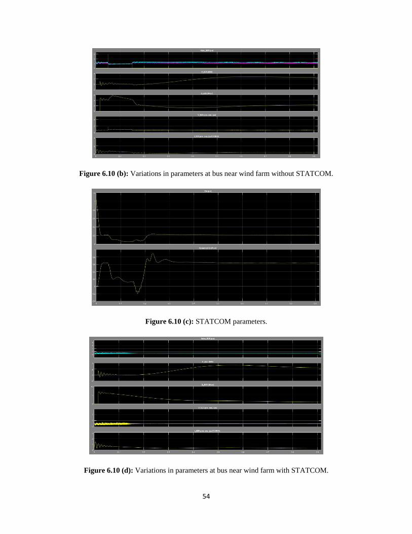
Figure 6.10 (b): Variations in parameters at bus near wind farm without STATCOM.
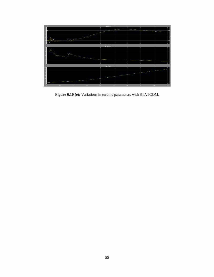
Figure 6.10 (c): STATCOM parameters.
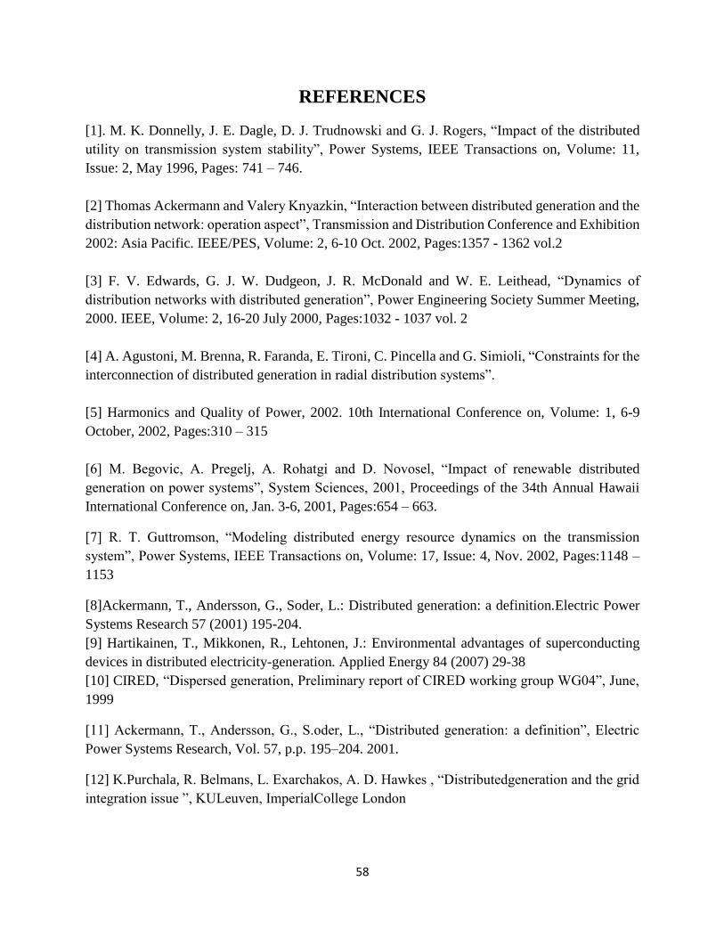
Figure 6.10 (d): Variations in parameters at bus near wind farm with STATCOM.
55
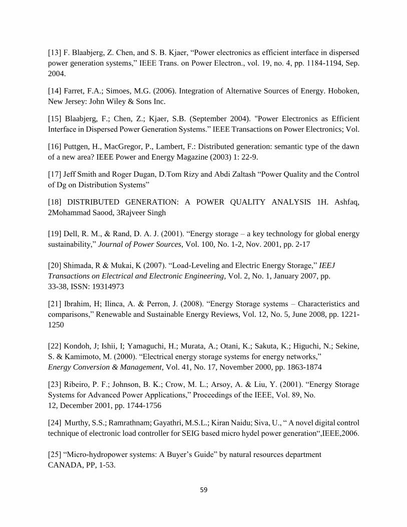
Figure 6.10 (e): Variations in turbine parameters with STATCOM.

56
CHAPTER-7
CONCLUSION
Small hydro plant is used as a DG at that places where conventional hydro plant is unable to
generate electricity due to less unavailability of water. It has major advantages over the
conventional nevertheless it has some drawbacks associated to rotor oscillations and unregulated
voltage at generator terminal ought to sudden change in load.
These issues are rectified by using Automatic Voltage Regulator and Power System Stabilizer.
AVR regulates generator terminal voltage and PSS is used to damp out the rotor oscillations.
STATOM is connected with the system to compensate for reactive power demand by the system,
improving overall power quality. It compensates reactive power by injecting quadrature
component of line current into the system with in quadrature phase with the system.

57
CHAPTER-8
FUTURE SCOPE
Distributed generation has a great scope in the improvement of performance of distribution system.
It improves the reliability, generate clean energy and much more cost effective. The size of DG
has variable range
Eco-friendly; it is clean energy and it doesn’t emit greenhouse gases which cause
degradation of air and acid rain as well.
Renewable resource; it will not exhaust or deplete over the year. It doesn’t have cost of
fuel.
Leads to employment.
Boosts public health.
Less maintenance of facilities.
58
REFERENCES
[1]. M. K. Donnelly, J. E. Dagle, D. J. Trudnowski and G. J. Rogers, “Impact of the distributed
utility on transmission system stability”, Power Systems, IEEE Transactions on, Volume: 11,
Issue: 2, May 1996, Pages: 741 – 746.
[2] Thomas Ackermann and Valery Knyazkin, “Interaction between distributed generation and the
distribution network: operation aspect”, Transmission and Distribution Conference and Exhibition
2002: Asia Pacific. IEEE/PES, Volume: 2, 6-10 Oct. 2002, Pages:1357 - 1362 vol.2
[3] F. V. Edwards, G. J. W. Dudgeon, J. R. McDonald and W. E. Leithead, “Dynamics of
distribution networks with distributed generation”, Power Engineering Society Summer Meeting,
2000. IEEE, Volume: 2, 16-20 July 2000, Pages:1032 - 1037 vol. 2
[4] A. Agustoni, M. Brenna, R. Faranda, E. Tironi, C. Pincella and G. Simioli, “Constraints for the
interconnection of distributed generation in radial distribution systems”.
[5] Harmonics and Quality of Power, 2002. 10th International Conference on, Volume: 1, 6-9
October, 2002, Pages:310 – 315
[6] M. Begovic, A. Pregelj, A. Rohatgi and D. Novosel, “Impact of renewable distributed
generation on power systems”, System Sciences, 2001, Proceedings of the 34th Annual Hawaii
International Conference on, Jan. 3-6, 2001, Pages:654 – 663.
[7] R. T. Guttromson, “Modeling distributed energy resource dynamics on the transmission
system”, Power Systems, IEEE Transactions on, Volume: 17, Issue: 4, Nov. 2002, Pages:1148 –
1153
[8]Ackermann, T., Andersson, G., Soder, L.: Distributed generation: a definition.Electric Power
Systems Research 57 (2001) 195-204.
[9] Hartikainen, T., Mikkonen, R., Lehtonen, J.: Environmental advantages of superconducting
devices in distributed electricity-generation. Applied Energy 84 (2007) 29-38
[10] CIRED, “Dispersed generation, Preliminary report of CIRED working group WG04”, June,
1999
[11] Ackermann, T., Andersson, G., S.oder, L., “Distributed generation: a definition”, Electric
Power Systems Research, Vol. 57, p.p. 195–204. 2001.
[12] K.Purchala, R. Belmans, L. Exarchakos, A. D. Hawkes , “Distributedgeneration and the grid
integration issue ”, KULeuven, ImperialCollege London
59
[13] F. Blaabjerg, Z. Chen, and S. B. Kjaer, “Power electronics as efficient interface in dispersed
power generation systems,” IEEE Trans. on Power Electron., vol. 19, no. 4, pp. 1184-1194, Sep.
2004.
[14] Farret, F.A.; Simoes, M.G. (2006). Integration of Alternative Sources of Energy. Hoboken,
New Jersey: John Wiley & Sons Inc.
[15] Blaabjerg, F.; Chen, Z.; Kjaer, S.B. (September 2004). "Power Electronics as Efficient
Interface in Dispersed Power Generation Systems.” IEEE Transactions on Power Electronics; Vol.
[16] Puttgen, H., MacGregor, P., Lambert, F.: Distributed generation: semantic type of the dawn
of a new area? IEEE Power and Energy Magazine (2003) 1: 22-9.
[17] Jeff Smith and Roger Dugan, D.Tom Rizy and Abdi Zaltash “Power Quality and the Control
of Dg on Distribution Systems”
[18] DISTRIBUTED GENERATION: A POWER QUALITY ANALYSIS 1H. Ashfaq,
2Mohammad Saood, 3Rajveer Singh
[19] Dell, R. M., & Rand, D. A. J. (2001). “Energy storage – a key technology for global energy
sustainability,” Journal of Power Sources, Vol. 100, No. 1-2, Nov. 2001, pp. 2-17
[20] Shimada, R & Mukai, K (2007). “Load-Leveling and Electric Energy Storage,” IEEJ
Transactions on Electrical and Electronic Engineering, Vol. 2, No. 1, January 2007, pp.
33-38, ISSN: 19314973
[21] Ibrahim, H; Ilinca, A. & Perron, J. (2008). “Energy Storage systems – Characteristics and
comparisons,” Renewable and Sustainable Energy Reviews, Vol. 12, No. 5, June 2008, pp. 1221-
1250
[22] Kondoh, J; Ishii, I; Yamaguchi, H.; Murata, A.; Otani, K.; Sakuta, K.; Higuchi, N.; Sekine,
S. & Kamimoto, M. (2000). “Electrical energy storage systems for energy networks,”
Energy Conversion & Management, Vol. 41, No. 17, November 2000, pp. 1863-1874
[23] Ribeiro, P. F.; Johnson, B. K.; Crow, M. L.; Arsoy, A. & Liu, Y. (2001). “Energy Storage
Systems for Advanced Power Applications,” Proceedings of the IEEE, Vol. 89, No.
12, December 2001, pp. 1744-1756
[24] Murthy, S.S.; Ramrathnam; Gayathri, M.S.L.; Kiran Naidu; Siva, U., “ A novel digital control
technique of electronic load controller for SEIG based micro hydel power generation“,IEEE,2006.
[25] “Micro-hydropower systems: A Buyer’s Guide” by natural resources department
CANADA, PP, 1-53.
60
[26] M. De Bortoli,; M. Groppo,; G.Stanic, “High Performance Direct Driven Hydroelectric
Generators for Mini-Micro Power Stations” XIX- ICEM, 2010, Rome.
[27] Cristian Dragos Dumitru; AdrianGligor, “Modeling and simulation of renewable hybrid
power system using MATlab Simulink environment”, Scientific Bulletin of the Petru Major
University of Targu Mures Vol. 7 (XXIV), No. 2, 2010, pp 5-9.
[28] Demiron, A.; Zeynelgil, H.L., “Modelling and simulation of synchronous machine transient
analysis using simulink”, International Journal of Electrical engineering, 39/4, pp, 337-346.
[29] M.G.Molina,; M.Pacas, “Improved Power Conditioning System of Micro-Hydro Power
Plant for Distributed Generation Applications”, IEEE, 2010, pp,1733-1738.
[30] IEEE committee report, “Hydraulic Turbine and Turbine Control Models for System Dynamic Studies
– 1992. [31] IEEE committee report, computer presentation of excitation systems, IEEE Trans. Vol. PAS-
87, No. 6, June 1968, pp. 1460-1470. [32] D. G. Ramey and J. W. Skooglund hydro governor representation
for system stability study IEEE Trans. Vol. PAS-89, pp. 106-112, 1970.
[33] H. A. Kojori, S. B. Dewan and J. D. Lavers, "A large-scale PWM solid-state synchronous condenser,"
IEEE Transactions on Industry Applications, vol. 28, no. 1, 1992.
[34] Prabha Kundur, Power System Stablity and Control, McGraw-hill, INC., 1994.