2014 DOE VEHICLE TECHNOLOGY PROGRAM REVIEW JUNE 16-20, 2014
ICME Guided Development of Advanced Cast Aluminum Alloys For
Automotive Engine Applications
Mei Li (PI) Ford Motor Company
June 19, 2014
1
Project ID: PM060
This presentation does not contain any proprietary, confidential, or otherwise restricted information
2014 DOE VEHICLE TECHNOLOGY PROGRAM REVIEW JUNE 16-20, 2014
Overview
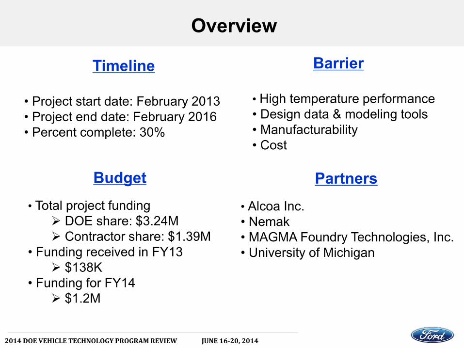
Timeline • Project start date: February 2013 • Project end date: February 2016 • Percent complete: 30%
Barrier
• High temperature performance • Design data & modeling tools • Manufacturability • Cost
Budget • Total project funding
DOE share: $3.24M Contractor share: $1.39M
• Funding received in FY13 $138K
• Funding for FY14 $1.2M
Partners • Alcoa Inc. • Nemak • MAGMA Foundry Technologies, Inc. • University of Michigan

2014 DOE VEHICLE TECHNOLOGY PROGRAM REVIEW JUNE 16-20, 2014
Project Objectives
• To develop a new class of advanced, cost competitive aluminum casting alloys providing a 25% improvement in component strength relative to components made with A319 or A356 alloys for high-performance engine applications.
• To demonstrate the power of Integrated Computational Materials Engineering (ICME) tools for accelerating the development of new materials and processing techniques, as well as to identify the gaps in ICME capabilities.
• To develop comprehensive cost models to ensure that components manufactured with these new alloys do not exceed 110% of the cost using incumbent alloys A319 or A356.
• To develop a technology transfer and commercialization plan for deployment of these new alloys in automotive engine applications.

2014 DOE VEHICLE TECHNOLOGY PROGRAM REVIEW JUNE 16-20, 2014
Approach
Task 1.0 – Project Management and Planning
Task 2.0 – ICME Guided Alloy Development
Task 3.0 – ICME Tools Gap Analysis
Task 4.0 – Demonstration and Validation of New Alloys
on Engine Components
Task 5.0 – Cost Model Development and Planning

2014 DOE VEHICLE TECHNOLOGY PROGRAM REVIEW JUNE 16-20, 2014
Deliverables and Timeline

2014 DOE VEHICLE TECHNOLOGY PROGRAM REVIEW JUNE 16-20, 2014
Targeted Properties
Property Cast Aluminum Baseline
Cast Lightweight Alloy Targets
Key Properties
Tensile Strength (Ksi) 33 KSI 40 KSI Key
Yield Strength (Ksi) 24 KSI 30 KSI Key
Density 2.7 g/cm3 < 6.4 g/cm3 Key
Elongation (%) 3.50% 3.50%
Shear Strength 26 KSI 30 KSI
Endurance Limit 8.5 KSI 11 KSI
Fluidity (Die Filling Capacity/Spiral Test)
Excellent Excellent Key
Hot Tearing Resistance Excellent Excellent Key
High Temperature Performance
@ 250C @ 300 C
Tensile Strength (KSI) 7.5KSI @ 250 C 9.5 KSI @ 300 C Key
Yield Strength (KSI) 5 KSI @ 250 C 6.5 KSI @ 300 C Key
Elongation in 2” 20% @ 250 C < 20% @ 300 C

2014 DOE VEHICLE TECHNOLOGY PROGRAM REVIEW JUNE 16-20, 2014
• Effect of Alloy Elements on Mechanical Properties Based on A356 Alloy
Alloy
RT Tensile Properties
at 250C (after 100hrs-250C holding)
at 300C (after 100hrs-300C holding)
0.2% YS (MPa)
UTS (MPa) E % 0.2% YS
(MPa) UTS
(MPa) E % Creep õ0.1-100h
0.2% YS (MPa)
UTS (MPa) E % Creep
õ0.1-100h
A356 T7 257 299 9.9 55 61 34.5 38.8 40 43 34.5 21.7
A356+Cu 0.50% T7 275 327 9.8 66 73 34.5 39.5 40 44 34.6 21.8
A356+Cu 0.50%+Zr 0.14%+Mn0.15% T7 264 319 11.3 65 76 37 41 44 51 46 22.5
AlSi7Cu3.3 MnVZrTi T7 195 335 8 95 124 19 tbm 66 75 26 tbm
AlSi7Cu3.8 MnVZrTi T7 234 368 6 102 133 19 63 77 26 31.8
Background

2014 DOE VEHICLE TECHNOLOGY PROGRAM REVIEW JUNE 16-20, 2014
• Improved Mechanical Properties at Room Temperature and 150oC
Alloy Room Temperature(22C) High Temperature(150C)
YS(MPa) UTS(MPa) E(%) YS(MPa) UTS(MPa) E(%)
5Si1Cu0.6Mg 337.27 369.99 2.8 307.98 325.9 6 7Si1Cu0.5Mg 338.76 385.38 5.5 305.23 328.65 10
7Si1Cu0.5Mg3Zn 346.45 392.39 4.7 310.74 332.79 7.7 5Si1Cu0.5Mg 332.79 368.96 3.2 307.98 325.9 6 5Si3Cu0.5Mg 373.09 404.33 2 334.17 361.73 4
5Si3Cu0.5Mg3Zn 372.63 391.35 2 328.65 345.88 2 5Si1Cu0.6Mg 335.31 373.09 3.2 307.98 325.9 6
5Si1Cu0.6Mg3Zn 346.45 328.05 2.2 314.87 334.17 5.7 5Si1Cu0.6Mg 329.34 371.03 4 307.98 325.9 6 7Si3Cu0.6Mg 376.65 407.31 2 337.61 368.62 4.3
7Si3Cu0.6MgZn 379.06 401.34 2 333.48 352.77 5
5Si1Cu0.6Mg 329.92 368.84 3.2 307.98 325.9 6
Background
2014 DOE VEHICLE TECHNOLOGY PROGRAM REVIEW JUNE 16-20, 2014
Casting and Testing Facility
Micro-Computer
Hydraulic Testing
Machine
FT εT vs. t
pyrometer
extensometerInductionHeating
load cell
ε vs. t
Micro-Computer
Hydraulic Testing
Machine
Hydraulic Testing
Machine
FT εT vs. t
pyrometer
extensometerextensometerInductionHeating
InductionHeating
load cellload cell
ε vs. t
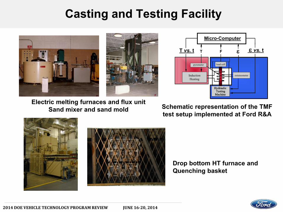
Schematic representation of the TMF test setup implemented at Ford R&A
Electric melting furnaces and flux unit Sand mixer and sand mold
Drop bottom HT furnace and Quenching basket

2014 DOE VEHICLE TECHNOLOGY PROGRAM REVIEW JUNE 16-20, 2014
• Based on Ford’s large I4 Architecture • Complete new Cylinder Head Design • New Feature Content
Under DOE Contract DE-EE0003332
Design Requirements
• 14 mm spark plug w/transverse fuel injector location
• Bosch and MM fuel injector (protect for both injectors)
• Two piece water jacket (cross / split cooling)
• Cross flow coolant path (lower jacket)
• Longitudinal coolant path (upper jacket)
• 8.5 mm chamber wall w/ additional IEM / chamber support
• AS7GU material
• 10
spark plug angle / 6
injector angle
• 31.8 mm (X2) intake valve diameter at a 18
angle
• 28.5 mm (X2) exhaust valve diameter at a 18.4
angle
• Outboard intake and exhaust HLA
Demonstration on Ford GTDI Engine Program

2014 DOE VEHICLE TECHNOLOGY PROGRAM REVIEW JUNE 16-20, 2014
Cost Modeling
Technical Cost Model - Sand Casting Process Flow Diagram Assumption
Melt Sand Cast
Molding
Machining
Recyclable/Clean Scrap
Dross
Virgin Ingot
Sell Scrap Materials
Finished Parts
DirtyScrap
Sand
Pattern
Heat treat
Re-melt Disassemble
Dry mold
Degate
Reclaim sand
Scrap sand
Scrap Stream B
Scrap Stream A
Scrap Stream C
Raw Material Production

2014 DOE VEHICLE TECHNOLOGY PROGRAM REVIEW JUNE 16-20, 2014
Initial Alloy Design
[1]
[2]
[4] [5]
[6]
[7]
[8] [6] [3]
[3]
[1] Y J Li, S Brusethaug and A Olsen, Scripta Mater, 54 (2006) 99-103. [2] S G Shabestari and H Moemeni, J Mater Process Technol, 153-154 (2004) 193-198. [3] M Zeren, J Mater Process Technol, 169 (2005) 292-298. [4] P Ouellet and F H Samuel, J Mater Sci, 34 (1999) 4671-4697. [5] J Tavitas-Medrano, J E Gruzleski, F H Samuel, S Valtierra and H W Doty, Mater Sci Eng A, 480 (2008) 356-364. [6] M Garat, US20110126947, 2011. [7] J C Lin, X Yan, C Yanar, L D Zellman, X Dumant and R Tombari, US7625454, 2009. [8] H A Elhadari, H A Patel, D L Chen and W Kasprzak, Mater Sci Eng, 528 (2011) 8128-8138.
Effectiveness of Alloying Additions Yield Strength Contour Map

2014 DOE VEHICLE TECHNOLOGY PROGRAM REVIEW JUNE 16-20, 2014
• Precipitation Vol. % @ 300 C (Al7Si): (ThermoCalc)
• Scheil Solidification Simulation • (ThermoCalc & Pandat)
Q
Q
Initial Alloy Design

2014 DOE VEHICLE TECHNOLOGY PROGRAM REVIEW JUNE 16-20, 2014
13 alloy compositions have been proposed and cast.
Heat 1-7 Si-Fe-Cu-Mg-V-Zr-Ni.
To compare the mechanical properties of these alloys with DOE
criteria.
Heat 8-13 Si-Ti-V-Zr-Ni
To investigate the effect of Ti, V, Zr and Ni.
Initial Alloy Design: Heat 1-13

2014 DOE VEHICLE TECHNOLOGY PROGRAM REVIEW JUNE 16-20, 2014
(a) Melting raw materials @ 750 C.
(c)
Alloy Fabrication- Permanent Mold Gravity Cast
(b) Pouring spectrometer standard disk to control melt composition.
(c) Pouring torpedo shape sample. (d) Torpedo samples ready for analysis.

2014 DOE VEHICLE TECHNOLOGY PROGRAM REVIEW JUNE 16-20, 2014 6
Si
Zr-rich Q+
Microstructure of Heat 4 (As Cast) Optical BSE
50μm
Al Si
Zr V Ti
Zr-rich
Q BSE
SEM-EDS Analysis of “Zr-rich Phase” in Heat 4 (As cast)
Zr-rich Phase– contains Zr, Ti, V. U of Michigan

2014 DOE VEHICLE TECHNOLOGY PROGRAM REVIEW JUNE 16-20, 2014

2014 DOE VEHICLE TECHNOLOGY PROGRAM REVIEW JUNE 16-20, 2014
Tensile Testing of Heat 1-7 (T6) • @ RT • @ 300 C
Heat 1-7 alloys fulfill DOE yield strength criteria at both RT and 300 C. @ RT and 300 C, heat 1-7 alloys exhibit lower yield strength than AS7GU due to lower
(Cu+Mg) levels. When tested @ 300 C after 100 hour thermal exposure, heat 7 alloy shows yield
strength comparable to AS7GU (or better).
DOE

2014 DOE VEHICLE TECHNOLOGY PROGRAM REVIEW JUNE 16-20, 2014
Hardness Comparison between Heat 7 & AS7GU (T6) after Thermal Exposure @ 300oC
Difference in hardness between heat 7 and AS7GU is reversed after thermal exposure @ 300 C. Effect of V, Zr & Ni additions?

2014 DOE VEHICLE TECHNOLOGY PROGRAM REVIEW JUNE 16-20, 2014
Morphology of Precipitates in Heat 7
Q: Al-Si-Cu-Mg
High-Ni High-Zr
High-V
BF-STEM
A variety of precipitates with relatively fine size exist in heat 7, even after thermal exposure @ 300 C for 100 hours.
Heat 7 (T6 + 300C/100hr exposure) Heat 7H (T6)
Q: Al-Si-Cu-Mg
High-Zr
High-V
2014 DOE VEHICLE TECHNOLOGY PROGRAM REVIEW JUNE 16-20, 2014
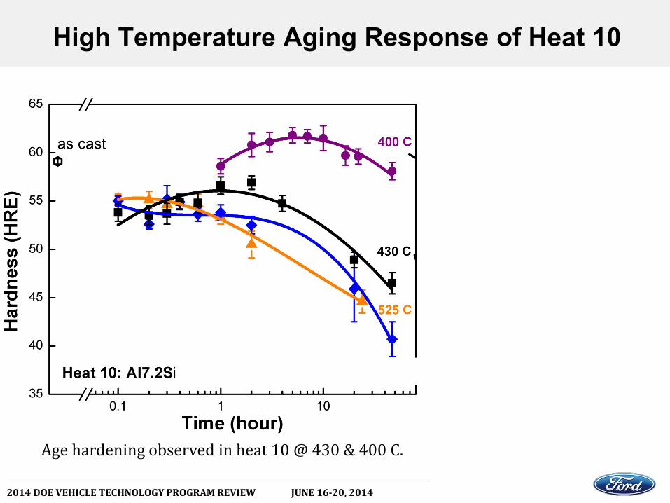
High Temperature Aging Response of Heat 10
Age hardening observed in heat 10 @ 430 & 400 C.

2014 DOE VEHICLE TECHNOLOGY PROGRAM REVIEW JUNE 16-20, 2014
Comparison of Aging Response of Heat 8-13
Alloys with higher levels of V, Zr and Ni exhibit stronger aging response @ 430 C.

2014 DOE VEHICLE TECHNOLOGY PROGRAM REVIEW JUNE 16-20, 2014
Summary
• The program was kicked off in February 2013. • CALPHD method was applied to explore and determine the
initial 13 alloy compositions. • Heat 1-7 alloys meet DOE criteria on yield strength at RT and
300 C, even with 100 hour thermal exposure at testing temperature.
• (Cu+Mg) level is key to RT strength. Much higher RT strength could be attained by optimize the Al-Si-Cu-Mg baseline composition.
• V, Zr, Ni are beneficial for high temperature strength, particularly after long time thermal exposure. High temperature strength could be potentially improved by optimizing the aging heat treatment for these heat resistant precipitates.

2014 DOE VEHICLE TECHNOLOGY PROGRAM REVIEW JUNE 16-20, 2014
Future Work
• Continue to investigate the strengthening mechanisms of Al-Cu-Mg-Si-V-Zr-Ni-Ti at room and high temperature using combined ICME and TEM approach.
• Optimize alloy compositions and heat treatment to achieve sufficient volume fraction and effective size and morphology for the heat resistant precipitates.
• Continue to investigate the fatigue and thermal mechanical fatigue performance of the new alloys.
• Continue to investigate the gaps of ICME models in modeling the casting process, microstructural evolution and mechanical properties.
• Continue to establish the cost model for these new alloys to ensure not to exceed 110% of the cost of incumbent alloys A319 or A356.