INV ITEDP A P E R
Hybrid Optical RFAirborne CommunicationsThese communication systems provide high throughput for mobile long-range
networks by combining the reliability of radio frequency links with the
high capacity and low cost of optical links.
By Larry B. Stotts, Fellow IEEE, Larry C. Andrews, Senior Member IEEE,
Paul C. Cherry, Member IEEE, James J. Foshee, Member IEEE,
Paul J. Kolodzy, Senior Member IEEE, William K. McIntire, Malcolm Northcott,
Ronald L. Phillips, Senior Member IEEE, H. Alan Pike, Brian Stadler, and
David W. Young, Senior Member IEEE
ABSTRACT | The use of hybrid free-space optical (FSO)/radio-
frequency (RF) links to provide robust, high-throughput com-
munications, fixed infrastructure links, and their associated
networks have been thoroughly investigated for both com-
mercial and military applications. The extension of this
paradigm to mobile, long-range networks has long been a
desire by the military communications community for multi-
gigabit mobile backbone networks. The FSO communications
subsystem has historically been the primary limitation. The
challenge has been addressing the compensation of propaga-
tion effects and dynamic range of the received optical signal.
This paper will address the various technologies required to
compensate for the effects referenced above. We will outline
the effects FSO and RF links experience and how we overcome
these degradations. Results from field experiments conducted,
including those from the Air Force Research Laboratory
Integrated RF/Optical Networked Tactical Targeting Network-
ing Technologies (IRON-T2) program, will be presented.
KEYWORDS | Communication system field trials; free-space
optical communications; gigabit communications; hybrid com-
munication; long-range communications; optical turbulence
compensation; radio-frequency (RF) communications
I . INTRODUCTION
There is a need for high-capacity communications networks
for high-throughput applications [1]. The military typically
transmits and receives video, voice, chat, and other
important information simultaneously among various dis-
mounted, maneuver force elements, airborne and maritime
assets, and the upper echelons. New, unallocated spectrum
must be utilized if the projected future military requirementsare to be met, given the oversubscription of VHF-UHF-L
band (30 MHz–1.55 GHz frequencies). The spectrum
regimes that appear to fit these criteria are free-space optical
(FSO) and radio frequencies (RF) in higher bands such as
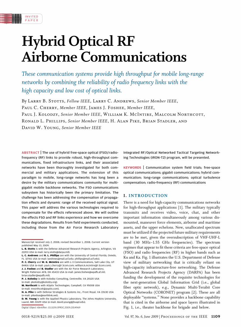
Ku and Ka. Fig. 1 illustrates the U.S. Department of Defense
view of military networking that is critically reliant on
high-capacity infrastructure-free networking. The Defense
Advanced Research Projects Agency (DARPA) has beenfunding the development of the requisite technologies for
the next-generation Global Information Grid (i.e., global
fiber optic network), e.g., Dynamic Multi-Terabit Core
Optical Networks (CORONET) program [2]. These are all
deployable Bsystems.[ None provides a backbone capability
that is cited in the airborne and space layers illustrated in
Fig. 1, i.e., theater backbone for brigade and below.
Manuscript received July 2, 2008; revised December 1, 2008. Current version
published May 13, 2009.
L. B. Stotts is with the Defense Advanced Research Projects Agency, Arlington, VA
22203 USA (e-mail: [email protected]).
L. C. Andrews and R. L. Phillips are with the University of Central Florida, Oviedo,
FL 32765 USA (e-mail: [email protected]; [email protected]).
P. C. Cherry and W. K. McIntire are with L-3 Communications, Salt Lake City, UT
84416 USA (e-mail: [email protected]; [email protected]).
J. J. Foshee and B. Stadler are with the Air Force Research Laboratory,
Wright Patterson AFB, OH 45433 USA (e-mail: [email protected];
P. J. Kolodzy is with Kolodzy Consulting, Centreville, VA 20120 USA
(e-mail: [email protected]).
M. Northcott is with AOptix Technologies, Campbell, CA 95008 USA
(e-mail: [email protected]).
H. A. Pike is with Defense Strategies & Systems Inc., Front Royal, VA 22630 USA
(e-mail: [email protected]).
D. W. Young is with the Applied Physics Laboratory, The Johns Hopkins University,
Laurel, MD 21029 USA (e-mail: [email protected]).
Digital Object Identifier: 10.1109/JPROC.2009.2014969
Vol. 97, No. 6, June 2009 | Proceedings of the IEEE 11090018-9219/$25.00 �2009 IEEE
To meet that void, research and development has been
ongoing into airborne high-speed backbones for tactical
applications [3], mostly sponsored by the U.S. Air Force,
e.g., the Air Force Research Laboratory, Sensor Director-
ate (AFRL/SN) [4]–[7]. Those efforts were primarily im-
plementing FSO communication links and eventually
developing hybrid FSO/RF communication links [8].In the 1960s, the Air Force initiated efforts to develop
FSO communications. Field tests of FSO links between a
high-flying aircraft and a ground-based receiver were
conducted over ranges on the order of 100 km. The HAVE
LACE effort began in 1983 with the objective of determining
the feasibility of air-to-air laser communications between
two aircraft utilizing small, solid-state optical communica-
tion transceivers for data rates less than 1 Mbps [4]. HAVELACE was successful in meeting its technology objectives
and demonstrated that air-to-air laser communications was
possible using small off-the-shelf components. AFRL/SN
conducted a limited test using equipment to evaluate two
slightly modified terminals designed for space applications.
This test utilized terminals sighted on Haleakala, Maui, HI
and at Mauna Loa, HI, located 150 km away. Those tests
indicated limited capabilities.The follow-on program to HAVE LACE demonstrated at
Hawaii data rates of 1.1 Gbps full duplex communications
and then utilized an RF channel to begin the communica-
tion acquisition process. The hardware demonstrated in
this test formed the foundation for what became a follow-
on program to develop a suitable air-to-air system.
The Recc-Intel Cross Link (RICL) effort began in
late 1995 as an AFRL/SN program to develop an air-to-aircrosslink system capable of communicating between two
aircraft operating at 40 000 ft with separation ranges of
50 to 500 km. Objective data rates were 1 Gbps with a bit
error rate (BER) of 10�6. Unfortunately, the RICL effort
ran into development problems, and only limited ground
testing occurred with the system in 2004 and 2005. The
system utilized 810- and 850-nm-based components and
had fewer suppliers since commercial telecom compo-
nents had shifted to 1550 nm. Another problem with theRICL system was the excessive size and weight of the
gimbal system. The turret assembly alone for the RICL
weighed approximately 150 lbs. The Ultra-Wideband Laser
Communications for Intelligence, Surveillance and Recon-
naissance effort was to integrate a 1550-nm-based laser
communication system into a gimbal that was capable of
2.5 Gbps full duplex and a BER of 10�6 and operation at
40 000 ft and at ranges of 100 km. Limited ground testingof these terminals occurred and uncovered deficiencies in
the optical train that had to be rectified.
Thus the concept of FSO communications has been
around since the late 1960s [9]–[22]. Lasers offered the
potential for small transmitters and receivers with very
high antenna gain (that is, small transmitter apertures)
[23]–[27]. Specifically, FSO communication systems could
be much more efficient and provide orders of magnitudegains in data rate compared to an RF system of the same
size. Unfortunately, in the 1970s and 1980s, much of the
potential gain in efficiency was lost because of poor
electrical-to-optical efficiency, poor optical detector effi-
ciency, and the increased transmitter apertures necessitat-
ed by transmitter pointing-error limitations [28]–[30].
Also, the lifetime of laser transmitters and some key
subsystems available at the time were not good enough for apractical space system. So when all the dust cleared during
those decades, the advantages of FSO communications over
Fig. 1. Notional network centric architecture for the military.
Stotts et al . : Hybrid Optical RF Airborne Communications
1110 Proceedings of the IEEE | Vol. 97, No. 6, June 2009
RF communications were never realized, and the latterbecame the technology of choice for the past 40 years.
To achieve the goal of a robust high-throughput
airborne backbone communications network, innovative
hybrid networking and link technologies that exploit FSO/
RF channel diversity and synergy must be employed to
yield higher performance than either FSO or RF alone. The
first focused effort on hybrid FSO/RF communications was
the DARPA Optical RF Communications Link Experiment(ORCLE) program. Its primary focus was to research the
requisite networking and physical layer technologies for
networking radio and FSO nodes. The technology dem-
onstrations in ORCLE suggested that hybrid FSO/RF
communications was feasible and possibly could be pro-
totyped today. This recognition led DARPA to initiate the
Optical RF Communications Adjunct (ORCA) program
with AFRL, an effort to prototype the aforementionedhybrid system [8].
Since 2007, a more complete understanding of the key
attributes of an FSO communications system and the
development of advanced network routers has provided
the impetus to relook at developing a new tactical network
backbone capability [31], [32]. Besides DARPA, the AFRL
also began to investigate the efficacy of airborne hybrid
FSO/RF communications for such tactical applicationsafter the success of ORCLE. The Integrated RF/Optical
Networked Tactical Targeting Networking Technologies
(IRON-T2) program adapted the terminals developed
under the Multi-Platform-CDL program (MP-CDL) with
the development of a high-speed router and an optical
input. The optical input would allow interactive operation
with a companion FSO communications terminal. The
router was designed to accommodate short outages due toscintillation (optical). Requests for packet retransmission
would be through the RF channel, thus enabling the
combined FSO/RF wireless communications (hybrid).
Today, IRON-T2 experimentation is a key risk-reduction
activity supporting the DARPA/AFRL ORCA program.
This paper will describe the technical attributes that
motivate the development and use of hybrid FSO/RF
communication links. We shall describe recent efforts bythe IRON-T2 development team in demonstrating the
nascent FSO and network technologies. Results from
recent experiments also will be provided. These experi-
ments coupled with captive experiments have provided the
basis for a more complete understanding of the FSO
communications link. That has provided the authors to
more accurately model the FSO channel inclusive of the
application of adaptive optics. Those models are providingthe basis of understanding the reliability of airborne FSO
communication links and thus are critical for the
development of a prototype airborne hybrid FSO/RF
communications network. This effort provides risk miti-
gation for the ORCA prototype effort. It should be noted
that although this effort is motivated by military-based
communications needs, it has direct relevancy to all
mobile backbone networks under consideration for com-mercial applications.
II . MOTIVATION FORFSO/HYBRID LINKS
The future of mobile networking is reliant on the
availability of high-throughput backbone networks to
provide backhaul and/or access to the Internet core. Boththe military and commercial networks that must operate
without fixed infrastructure need to provide this capability
organically. The commercial enterprises are investing in
fixed FSO links as an alternative to optical fibers for
deployment in metropolitan-area networks (MANs) due to
their attractive characteristics. Fixed-location FSO links are
very easy to deploy and have high capacity, ease, and low
cost of deployment, making them suitable for backbones inmilitary applications and also for MANs and extension of
existing MANs. The weather attenuation dependency for
FSO links is very high. RF links are more reliable than FSO
links and can be deployed as easily as FSO links but are not
considered for backbone networks due to their low
capacity. Thus, for both military and future commercial
backbone networks, the characteristics of hybrid FSO/RF
communications architectures are highly desirable.RF communications, wireless technology characterized
by high frequencies, originated more than a century ago.
While it has the advantages of both channel stability and a
strong resistance to cloud attenuation on its side, it also faces
significant practical limitations. Chief among these is low
data rate, which renders RF systems incapable of high-speed
transmissionVan essential component for an effective
backbone network. Rain can also negatively affect the RFsystem, causing degradation in unfavorable weather condi-
tions. FSO communications offers a solution to address the
issue of low data rate presented with RF systems. As
indicated above, FSO technology is not a panacea. It is only
the combination of these two communications modalities
that can provide both the requisite high data rate and
reliability needed for backbone communications for both
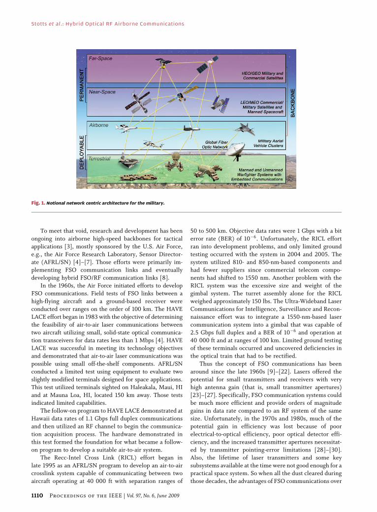
military and commercial applications.Table 1 shows the basic rationales for such a hybrid
approach. FSO communications can provide high-speed
transmission because of its naturally large and easily
available optical bandwidth, which can be much greater
than 10 Gbps. However, it is susceptible to weather effects,
especially clouds. RF communications has the disadvantage
of lower data rate because of spectrum availability but has a
more stable, reliable channel and operates better in clouds,but not as well in rain. In addition, RF links suffer from
multipath. On the other hand, FSO operates better in rain.
Thus the FSO should be enabled on clear/light haze/rainy
periods to provide the highest data rate, and the RF operate
when it is cloudy to provide the required high reliability. The
high directionality of FSO links substantially reduces the
probability of multipath. The table also cites another
Stotts et al . : Hybrid Optical RF Airborne Communications
Vol. 97, No. 6, June 2009 | Proceedings of the IEEE 1111
potential advantage for a hybrid approach: size, weight andpower (SWaP). Yet, there still are some challenges for both
FSO and RF link that must be addressed before a hybrid
FSO/RF network can be a reality. In other words, just having
them operate under the above atmospheric conditions is
necessary but not sufficient to ensure that the backbone
meets the robust system connectivity requirement.
The FSO tests in 2006 and the IRON-T2 Program in
2007, discussed earlier, demonstrated that many of thechallenges to accomplish reliable FSO and RF communica-
tions could be met under the appropriate conditions [33],
[34]. Its enabling technologies were sufficient to support
reliable FSO communications and provide insights on how
to significantly improve FSO performance in horizontal
links under nighttime and some daytime conditions. The
program also showed the effects of tropospheric dispersion
and multipath on an RF system’s BER. These technologies,and the resulting systems, need to be further developed to
increase performance and robustness.
III . IRON-T2 TECHNOLOGYDEMONSTRATOR
The IRON-T2 effort demonstrates the viability of the
requisite technology components for hybrid FSO/RF com-munications links. It incorporates high-speed adaptive
optics, a single-mode fiber optical modem, optical frequency
conversion, a simple forward error-correcting (FEC) code,
and optical automated gain control (AGC). The adaptive
optics provides more light into the fiber for improved signal-
to-noise ratio (SNR). The single-mode fiber-optical modem
provides an improved noise figure. The optical AGC
mitigates up to 50 dB of signal variation due to scintillation.These combine to provide a high-capacity 274 Mbps
X/Ku-band RF communications system.
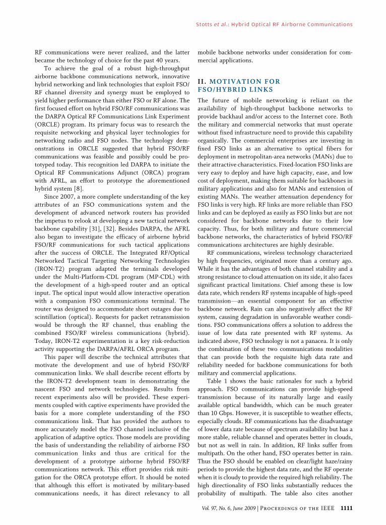
The results from testing on the IRON-T2 development
system provide the basis for the new development shown in
this paper. The testing was performed between the
mountains of Haleakala and Mauna Loa in Hawaii (see
Fig. 2). The results indicate that high-capacity optical links
are possible but that the uncorrected time-dependentvariations in received optical power due to atmospheric
attenuation and scintillation can reduce the quality of the
communications link. Launch power needs to be increased,
optical losses in the telescope need to be reduced, and the
tradeoffs among aperture size, launch power, and eye safety
must be considered.
Table 1 Generally Complementary Channel/Hybrid Characteristics for Airborne Networking
Fig. 2. IRON-T2 2006 experiment layout.
Stotts et al . : Hybrid Optical RF Airborne Communications
1112 Proceedings of the IEEE | Vol. 97, No. 6, June 2009
A. FSO SystemThe FSO experiment in 2006 addressed a number of
system configurations that were evaluated, including a single-
channel 2.5 Gbps transmission, a single-channel 10 Gbps
transmission, and a four-wavelength-division multiplexed
(WDM) channel transmission for an aggregate data rate of
40 Gbps (4 � 10 Gbps). The tests used optical modems
constructed with commercial-off-the-shelf (COTS) compo-
nents, and the optical telescope used adaptive optics (AO) toimprove the optical link availability. The AO performed
high-speed tracking and aberration correction to reduce the
effects of atmospheric scintillation.
The FSO terminals utilized a unique bidirectional,
adaptive optics method of beam control to compensate in
real-time for atmospheric turbulence and control the
diameter of the beam. A tip/tilt mirror arrangement
controlled fine pointing and tracking, while a deformablemirror corrected the perturbations caused by atmospheric
turbulence. The FSO terminals used AO compensated
laser-com terminals coupled to commercial 8-in (clear
aperture) telescopes. These terminals have a greater than
1 kHz closed-loop correction of approximately 30 Zernike
aberrations including tip/tilt and focus.
The WDM transmitter channels used were 1556.1,
1556.6, 1557.2, and 1557.6 nm. The high-speed data streamswere generated by multiplexing the four channels with a
polarization maintaining (PM) 1� 4 directional coupler and
encoding them with an electrooptic modulator. The data
sent were a pseudorandom bit sequence 27�1 pattern
encoded with a nonreturn-to-zero on–off key modulation
format. The modulator was followed by an erbium dopedfiber amplifier, which amplified the optical signal to about
200 mW at the output of the FSO terminal.
The WDM receiver used an optical preamplifier to
increase the received power to proper levels for input to
the digital communications analyzer, optical spectrum
analyzer, and BER test system. A microelectromechanical
systems tunable filter then selected the optical channel to
be evaluated. The 2.5 Gbps receiver used an APD with a10�9 BER sensitivity of �34 dBm, while the 10 Gbps
receiver used a PiN photodiode with a 10�9 BER sensitivity
of 10�18 dBm [31]–[33]. These sensitivities improved to
�36 and �24 dBm at 2.5 and 10 Gbps, respectively, when
an optical amplifier was used prior to the optical filter.
B. FSO PerformanceV2006Links supporting data rates from 2.5 to 40 Gbps were
observed for a period in excess of three contiguous hours
on each test day. The testing allowed a baseline of per-
formance to be established for FSO over the specific link
and provided data to support the development of designs to
improve link and system performance.
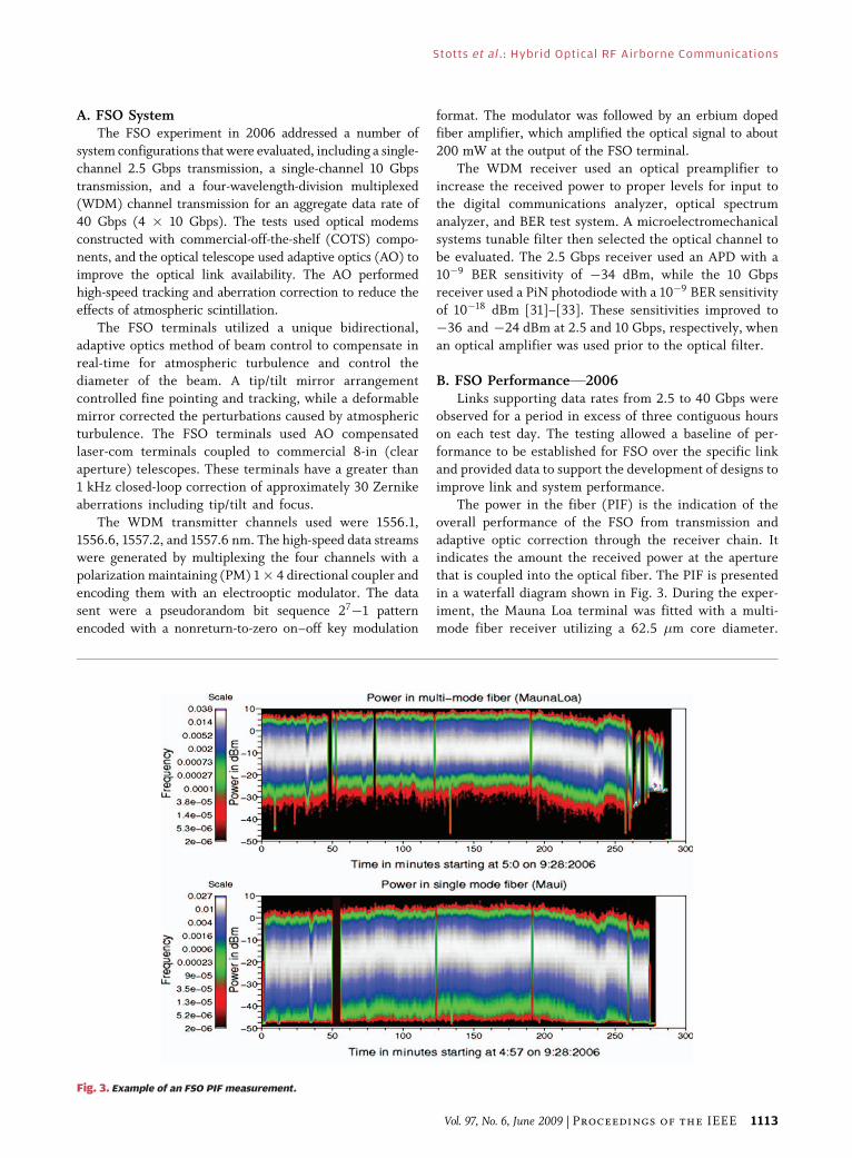
The power in the fiber (PIF) is the indication of the
overall performance of the FSO from transmission and
adaptive optic correction through the receiver chain. Itindicates the amount the received power at the aperture
that is coupled into the optical fiber. The PIF is presented
in a waterfall diagram shown in Fig. 3. During the exper-
iment, the Mauna Loa terminal was fitted with a multi-
mode fiber receiver utilizing a 62.5 �m core diameter.
Fig. 3. Example of an FSO PIF measurement.
Stotts et al . : Hybrid Optical RF Airborne Communications
Vol. 97, No. 6, June 2009 | Proceedings of the IEEE 1113
The Haleakala terminal was fitted with a single-mode fiber(SMF). Notice that the mean light level in the SMF is
lower than that in the multimode fiber. The SMF receiver
also shows more variability than the level in the multimode
fiber. Both the lower mean coupling and the increased
variability in the SMF case come from the reduced nu-
merical aperture and small fiber core of the SMF. Spe-
cifically, smaller angular and spatial light acceptances of
the SMF affect the received power in the fiber and anyBaperture averaging,[ respectively. Fortunately, the lower
light level of the SMF is compensated by the increased
sensitivity of single-mode detectors, the availability of an
optical AGC (OAGC), and FEC coding.
The conclusion from these experiments is that for
optical communications, we will have to address up to 30–
40 dB scintillation variations. This will be especially true
for a deployed airborne system, where the communicationdistances run from 50 to 200 km. As noted, other
techniques must be employed to supplement the output
from the AO system [3], [5], [6]. The OAGC and FEC used
for this purpose, combined in what we call an optical
modem, are described in detail in Section IV, including
their use in these Hawaii experiments.
C. FSO PerformanceV2007A similar FSO configuration was tested during the 2007
Iron T2 test. The optical modem was substantially
changedVone optical WDM channel at 3.125 Gbps was
dedicated for use with the Iron T2 hybrid link and a second
WDM channel at 10 Gb/s was used to characterize the
performance of a higher speed channel. An OAGC system
was brought to the test to address the residual optical
power variations. The performance of the hybrid channelwill be discussed later. The 10 Gb/s channel exhibited
much better performance than was seen in 2006, largely
due to the better receiver sensitivity and reduction of
phase errors in the receiver system provided by the OAGC.
The FSO link was also fully bidirectional in 2007.
Additional descriptions of the modem, the OAGC, and
their aggregate performance are in Section IV.
D. RF System and PerformanceThe IRON-T2 RF architecture is based on the MP-
CDL airborne system, which supports up to three
simultaneous, fully compliant CDL RF data links that
allow for data rates up to 274 Mbps, depending on range
and link conditions. The system can be configured to
operate in X- and/or Ku-band and typically operates in a
line-of-sight (LOS) air-to-ground or air-to-air link config-uration. The RF links are generally configured to
accommodate a specified data rate for a given range and
rain fade, typically operating with a few decibels of RF link
margin. However, for the Mauna Loa to Haleakala data
link tests, the RF system experienced additional fading
from other sources. The combination of littoral climate,
time-varying multipath reflections from the ocean, and
tropospheric effects caused severe fading, both flat andfrequency-selective, such that significant errors were
introduced into the RF link. Adaptive equalization is an
option to be implemented at the receiver to mitigate the
effects of multipath and improve the system performance.
The nature and extent of the fading ranged from
noticeable to severe throughout the test periods, depending
on atmospheric and weather conditions. Data analysis
indicates the most likely source of these dropouts was acombination of the tropospheric effects on the LOS path and
the multipath interference created by ocean reflections.
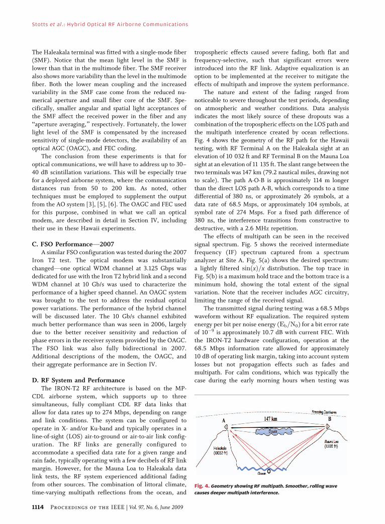
Fig. 4 shows the geometry of the RF path for the Hawaii
testing, with RF Terminal A on the Haleakala sight at an
elevation of 10 032 ft and RF Terminal B on the Mauna Loa
sight at an elevation of 11 135 ft. The slant range between the
two terminals was 147 km (79.2 nautical miles, drawing not
to scale). The path A-O-B is approximately 114 m longerthan the direct LOS path A-B, which corresponds to a time
differential of 380 ns, or approximately 26 symbols, at a
data rate of 68.5 Msps, or approximately 104 symbols, at
symbol rate of 274 Msps. For a fixed path difference of
380 ns, the interference transitions from constructive to
destructive, with a 2.6 MHz repetition.
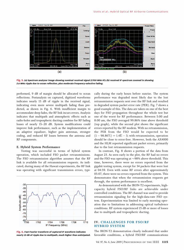
The effects of multipath can be seen in the received
signal spectrum. Fig. 5 shows the received intermediatefrequency (IF) spectrum captured from a spectrum
analyzer at Site A. Fig. 5(a) shows the desired spectrum:
a lightly filtered sinðxÞ=x distribution. The top trace in
Fig. 5(b) is a maximum hold trace and the bottom trace is a
minimum hold, showing the total extent of the signal
variation. Note that the receiver includes AGC circuitry,
limiting the range of the received signal.
The transmitted signal during testing was a 68.5 Mbpswaveform without RF equalization. The required system
energy per bit per noise energy (Eb=N0) for a bit error rate
of 10�9 is approximately 10.7 dB with current FEC. With
the IRON-T2 hardware configuration, operation at the
68.5 Mbps information rate allowed for approximately
10 dB of operating link margin, taking into account system
losses but not propagation effects such as fades and
multipath. For calm conditions, which was typically thecase during the early morning hours when testing was
Fig. 4. Geometry showing RF multipath. Smoother, rolling wave
causes deeper multipath interference.
Stotts et al . : Hybrid Optical RF Airborne Communications
1114 Proceedings of the IEEE | Vol. 97, No. 6, June 2009
performed, 9 dB of margin should be allocated to ocean
reflections. Postanalysis on captured, digitized waveforms
indicates nearly 15 dB of ripple in the received signal,
indicating even more severe multipath fading than pre-
dicted, as shown in Fig. 6. With insufficient margin to
accommodate deep fades, the RF link incurs errors. Analysisindicates that multipath and atmospheric effects such as
radio-holes and tropospheric ducting combine for RF fading
losses of nearly 15–20 dB. System modifications could
improve link performance, such as the implementation of
an adaptive equalizer, higher gain antennas, stronger
coding, and reduced RF losses between the antenna and
RF components.
E. Hybrid System PerformanceTesting was successful in terms of hybrid system
operation, which included FSO packet retransmissions.
The FSO retransmission algorithm assumes that the RF
link is available for all retransmission requests. As indi-
cated, during many of the Hawaii experiments, the RF link
was operating with significant transmission errors, typi-
cally during the early hours before sunrise. The system
performance was degraded most likely due to the lost
retransmission requests sent over the RF link and resulted
in degraded system packet error rate (PER). Fig. 7 shows a
good example of this. The data are taken on one of the best
days for FSO propagation throughout the whole test butone of the worst for RF performance. Between 5:00 and
8:00 am, the FSO averaged 99.86% time above threshold
(top graph), while the second plot shows the significant
errors reported by the RF modem. With no retransmission,
the PER from the FSO would be expected to be
ð1� 98:86%Þ ¼ 1:4E� 3; with retransmission, operation
should be close to error-free. However, both the AX4000
and the HLM reported significant packet errors, primarilydue to the lost retransmission requests.
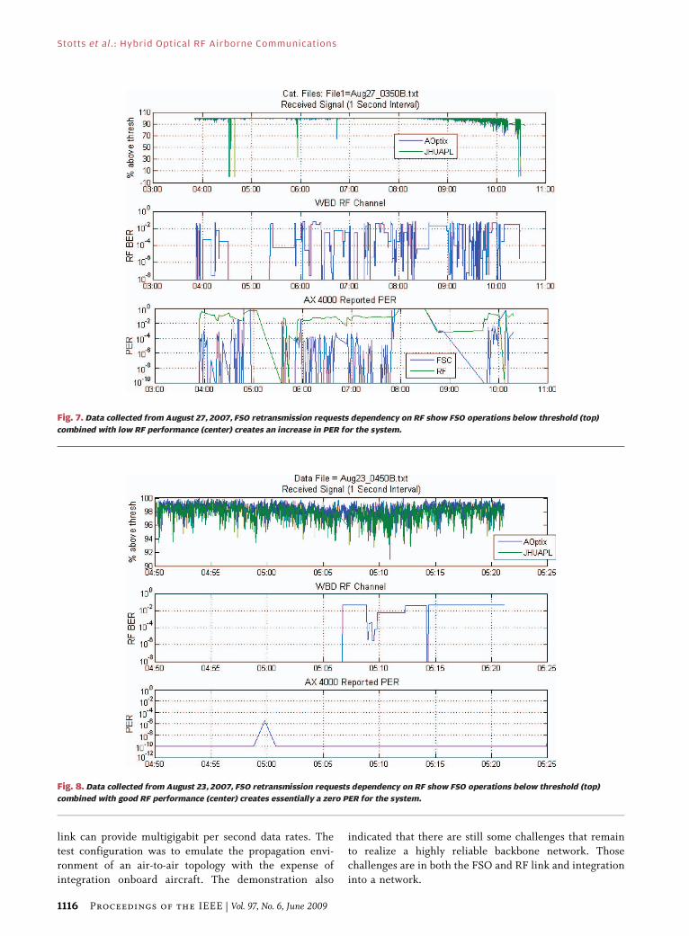
In contrast, Fig. 8 shows a portion of the data from
August 23. As seen early in the plot, the RF had no errors
and the FSO was operating at �98% above threshold. This
time, however, there were no errors reported from the
gigabit testing system, except for 34 packets that were lost
at 04:59. Even with some RF errors after approximately
05:07, there were no errors reported from the system. Thisdemonstrates that when the retransmission requests get
through, the system performance is excellent.
As demonstrated with the IRON-T2 experiments, high-
capacity hybrid FSO/RF links are achievable under
controlled conditions. The RF channel was used to provide
retransmission signaling for the high-data-rate FSO sys-
tem. Experimentation was limited to early morning oper-
ation due to limitations in addressing optical turbulenceconditions. RF system experienced 15 dB or more of losses
due to multipath and tropospheric ducting.
IV. CHALLENGES FOR FSO/RFHYBRID SYSTEM
The IRON-T2 demonstration clearly indicated that under
favorable conditions, a hybrid FSO/RF communications
Fig. 5. (a) Spectrum analyzer image showing nominal received signal (1700 MHz IF); (b) received IF spectrum zoomed in showing
2.6 MHz ripple due to ocean reflection, plus moderate frequency-selective fading.
Fig. 6. Fast Fourier transform of captured IF waveform indicates
nearly 15 dB of ripple due to multipath, much higher than anticipated.
Stotts et al . : Hybrid Optical RF Airborne Communications
Vol. 97, No. 6, June 2009 | Proceedings of the IEEE 1115
link can provide multigigabit per second data rates. The
test configuration was to emulate the propagation envi-
ronment of an air-to-air topology with the expense ofintegration onboard aircraft. The demonstration also
indicated that there are still some challenges that remain
to realize a highly reliable backbone network. Those
challenges are in both the FSO and RF link and integrationinto a network.
Fig. 7. Data collected from August 27, 2007, FSO retransmission requests dependency on RF show FSO operations below threshold (top)
combined with low RF performance (center) creates an increase in PER for the system.
Fig. 8. Data collected from August 23, 2007, FSO retransmission requests dependency on RF show FSO operations below threshold (top)
combined with good RF performance (center) creates essentially a zero PER for the system.
Stotts et al . : Hybrid Optical RF Airborne Communications
1116 Proceedings of the IEEE | Vol. 97, No. 6, June 2009
A. Challenges for an Effective Free-SpaceOptical Link
To achieve the promise of the very high-speed
communication of free-space laser links over long dis-
tances, several obstacles must be overcome. In addition to
clouds, which can block any single path, atmospheric
optical turbulence over tens or hundreds of kilometers can
disrupt such laser links. In particular, turbulence will
cause a spreading, constructive/destructive interferenceand wander in the laser beam, reducing power received at
the other end of the link. Atmospheric turbulence can also
cause fluctuations in the intensity of the received beam by
more than a factor of 1000.
AO systems can improve laser link performance but have
limitations imposed by the size of its apertures, the number
and bandwidth of their phase-compensating actuators, and
the distance over which it must operate. The lowest ordercorrection, tip/tilt, of the outgoing or incoming beam can
compensate for beam wander, wherever it occurs, except for
speed of light or actuator limitations. Higher order aberra-
tions, such as focus, astigmatism, and coma, can be corrected
by higher order AO corrections, but the range of influence is
limited by receiver aperture, number of AO actuators, and
system bandwidth. As a rule of thumb, the Rayleigh range
(also known as the Fresnel distance) can be used to estimatethe range over which AO will be useful. Simply stated,
aberrations that occur beyond that range cannot be resolved
by the transmitting or receiving telescopes and will not be
compensated by attempted phase adaptation.
The Rayleigh range is defined as the distance along the
propagation direction of a beam from the beam waist to the
location where the area of the cross section is doubled. A
laser communications system is assumed with a beam exitinga telescope of diameter D. From diffraction theory, we know
that range R where the beam is twice the cross-section of the
exit diameter can be derived from the relationship
ffiffiffi
2p
D � �R
D(1)
where � is the wavelength of light used in the systems.
If one wants to Nyquist sample the optical field at the
range R, then the imaging system needs to sample at
resolution equal to half this diameter. This implies that
Dffiffiffi
2p � �R
D
or
R � D2
ffiffiffi
2p
�¼ 0:7D2
�(2)
where D2=� is known as the Fresnel distance or Fresnellength from diffraction theory. For D ¼ 0:1 m, as used in
some recent experiments, we have
R � 0:7ð0:1 mÞ2=ð1:55� 10�6 mÞ¼ 4:5 km:
A similar set of logic would apply to AO sensing at thereceiver. The implication of the above is that compensa-
tion for turbulent fading and other effects can be effective
near the receiver but will be ineffective in compensating
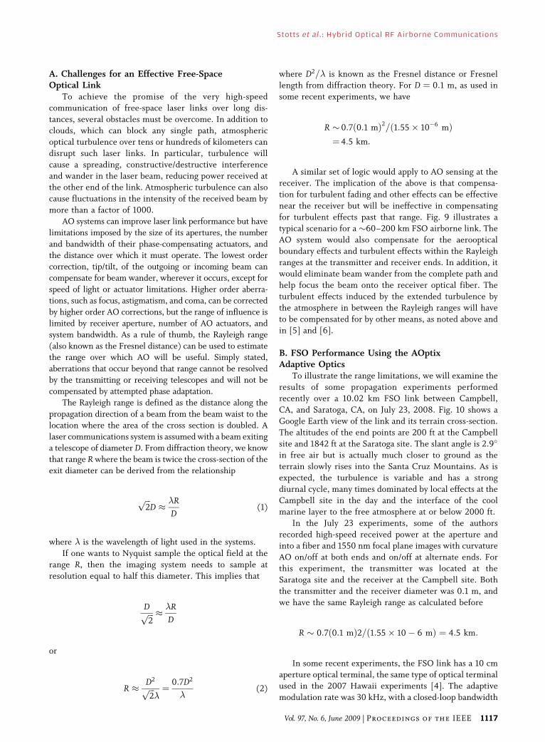
for turbulent effects past that range. Fig. 9 illustrates a
typical scenario for a �60–200 km FSO airborne link. The
AO system would also compensate for the aerooptical
boundary effects and turbulent effects within the Rayleigh
ranges at the transmitter and receiver ends. In addition, itwould eliminate beam wander from the complete path and
help focus the beam onto the receiver optical fiber. The
turbulent effects induced by the extended turbulence by
the atmosphere in between the Rayleigh ranges will have
to be compensated for by other means, as noted above and
in [5] and [6].
B. FSO Performance Using the AOptixAdaptive Optics
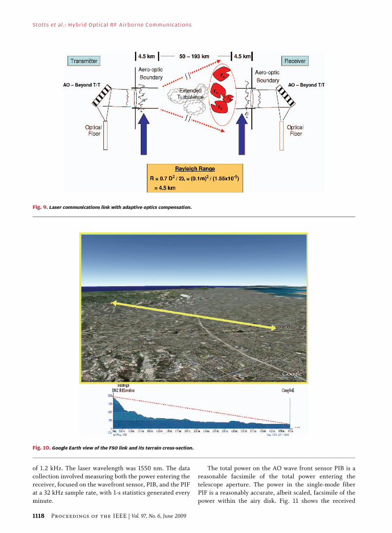
To illustrate the range limitations, we will examine the
results of some propagation experiments performed
recently over a 10.02 km FSO link between Campbell,
CA, and Saratoga, CA, on July 23, 2008. Fig. 10 shows a
Google Earth view of the link and its terrain cross-section.
The altitudes of the end points are 200 ft at the Campbell
site and 1842 ft at the Saratoga site. The slant angle is 2.9�
in free air but is actually much closer to ground as the
terrain slowly rises into the Santa Cruz Mountains. As is
expected, the turbulence is variable and has a strong
diurnal cycle, many times dominated by local effects at the
Campbell site in the day and the interface of the cool
marine layer to the free atmosphere at or below 2000 ft.
In the July 23 experiments, some of the authors
recorded high-speed received power at the aperture andinto a fiber and 1550 nm focal plane images with curvature
AO on/off at both ends and on/off at alternate ends. For
this experiment, the transmitter was located at the
Saratoga site and the receiver at the Campbell site. Both
the transmitter and the receiver diameter was 0.1 m, and
we have the same Rayleigh range as calculated before
R � 0:7ð0:1 mÞ2=ð1:55� 10� 6 mÞ ¼ 4:5 km:
In some recent experiments, the FSO link has a 10 cmaperture optical terminal, the same type of optical terminal
used in the 2007 Hawaii experiments [4]. The adaptive
modulation rate was 30 kHz, with a closed-loop bandwidth
Stotts et al . : Hybrid Optical RF Airborne Communications
Vol. 97, No. 6, June 2009 | Proceedings of the IEEE 1117
of 1.2 kHz. The laser wavelength was 1550 nm. The data
collection involved measuring both the power entering the
receiver, focused on the wavefront sensor, PIB, and the PIF
at a 32 kHz sample rate, with 1-s statistics generated every
minute.
The total power on the AO wave front sensor PIB is a
reasonable facsimile of the total power entering the
telescope aperture. The power in the single-mode fiber
PIF is a reasonably accurate, albeit scaled, facsimile of the
power within the airy disk. Fig. 11 shows the received
Fig. 9. Laser communications link with adaptive optics compensation.
Fig. 10. Google Earth view of the FSO link and its terrain cross-section.
Stotts et al . : Hybrid Optical RF Airborne Communications
1118 Proceedings of the IEEE | Vol. 97, No. 6, June 2009
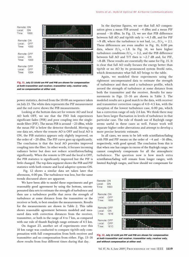
power statistics, derived from the 10:00 am sequence taken
on July 23. The white data represents the PIF measurement
and the red curve shows the PIB measurements.
Looking at the bottom data set for remote AO and local
AO both OFF, we see that the FSO link experiencessignificant fades (PIB) and poor coupling into the single-
mode fiber (PIF). The mean PIB is around�23 dBm, while
the mean PIF is below the detector threshold. Moving up
one data set, where the remote AO is OFF and local AO is
ON, the PIB statistics appears only slightly improved, on
the order of�20 dBm. The PIF curve goes up significantly.
The conclusion is that the local AO provides improved
coupling into the fiber. In other words, it focuses incomingradiance better but does not reduce scintillation/fading
significantly. When the remote is ON and the local is OFF,
the PIB statistics is significantly improved but the PIF is
little changed. The top data segment shows the PIB and PIF
statistics with both remote and local adaptive systems ON.
Fig. 12 shows a similar data set taken later that
afternoon, 4:00 pm. The turbulence was less, but the same
trends discussed above are apparent.We have been able to model these experiments and get
reasonably good agreement by using the bottom, uncom-
pensated data sets to estimate the strength of turbulence and
then use a turbulence profile that zeros the strength of
turbulence at some distance from the transmitter or the
receiver or both, to best emulate the measurements. Results
for the measurements are shown in Table 2. This table
shows reasonable agreement between modeled and mea-sured data with correction distances from the receiver,
transmitter, or both in the range of 4 to 7 km, as compared
with our rule of thumb Rayleigh range estimate of 4.5 km.
On August 23, another set of experiments over this
10 km range was conducted to compare tip/tilt-only com-
pensation with full compensation from both receiver and
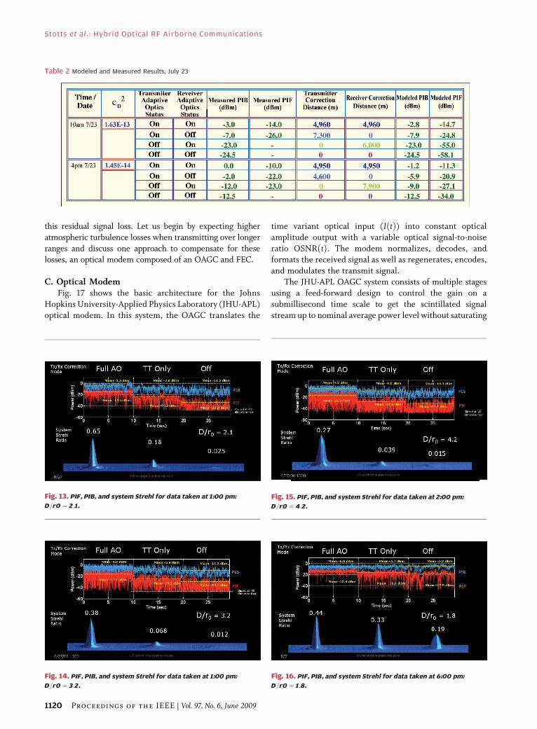
transmitter and no compensation from either. Figs. 13–16
show results from four different times during that day.
In the daytime figures, we see that full AO compen-sation gives a mean PIB around �4 dBm and a mean PIF
around �16 dBm. In Fig. 13, we see that PIB difference
between full AO and tip/tilt only is �4.3 dB, and for PIF
�9 dB, where the turbulence is not bad, i.e., D=r0 ¼ 2:1.
These differences are even smaller in Fig. 16, 6:00 pm
data, where D=r0 ¼ 1:8. In Fig. 14, we have higher
turbulence conditions D=r0 ¼ 3:2, and the PIB difference
between full AO and T/T then is �2.7 dB and, for PIF,�8 dB. These results are essentially the same for Fig. 15. It
is clear that full AO really focuses the energy better than
tip/tilt or no AO by its pronounced system Strehl ratio,
which demonstrates what full AO brings to the table.
Again, we modeled these experiments using the
rightmost uncompensated data to estimate the strength
of turbulence and then used a turbulence profile, which
zeroed the strength of turbulence at some distance fromboth the transmitter and the receiver. Results for mea-
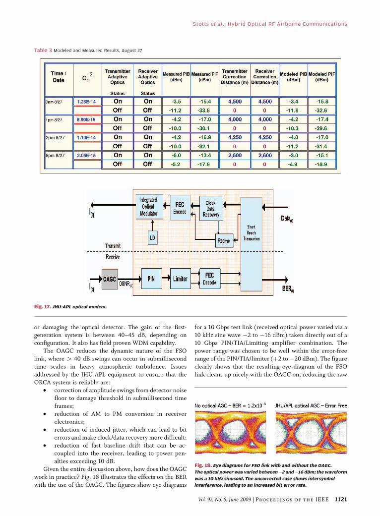
surements in Figs. 13–16 are shown in Table 3. The
modeled results are a good match to the data, with receiver
and transmitter correction ranges of 4.0–4.5 km, with the
exception of the lowest turbulence case, 6:00 pm, which
has a correction range of only 2.6 km. We think there may
have been larger fluctuation in levels of turbulence in that
particular case. The rule of thumb use of Rayleigh rangeseems useful in these cases as well. Future work will
separate higher order aberrations and attempt to develop a
more precise heuristic estimate.
In all cases, we seem to be left with scintillation/fading
with PIB and PIF means on the order of �4 and �16 dBm,
respectively, with good spread. The conclusion from this is
that when one has ranges in excess of the Rayleigh range, we
cannot completely compensate for all the atmosphericturbulence. The question now is how much extra
scintillation/fading will remain from longer ranges, with
limited Rayleigh ranges, and how should we compensate for
Fig. 11. July 23 10:00 am PIF and PIB are shown for compensation
at both transmitter and receiver, transmitter only, receiver only,
and no compensation at either end.
Fig. 12. July 23 4:00 pm PIF and PIB are shown for compensation
at both transmitter and receiver, transmitter only, receiver only,
and without compensation at either end.
Stotts et al . : Hybrid Optical RF Airborne Communications
Vol. 97, No. 6, June 2009 | Proceedings of the IEEE 1119
this residual signal loss. Let us begin by expecting higher
atmospheric turbulence losses when transmitting over longer
ranges and discuss one approach to compensate for theselosses, an optical modem composed of an OAGC and FEC.
C. Optical ModemFig. 17 shows the basic architecture for the Johns
Hopkins University-Applied Physics Laboratory (JHU-APL)
optical modem. In this system, the OAGC translates the
time variant optical input (IðtÞ) into constant optical
amplitude output with a variable optical signal-to-noise
ratio OSNRðtÞ. The modem normalizes, decodes, andformats the received signal as well as regenerates, encodes,
and modulates the transmit signal.
The JHU-APL OAGC system consists of multiple stages
using a feed-forward design to control the gain on a
submillisecond time scale to get the scintillated signal
stream up to nominal average power level without saturating
Table 2 Modeled and Measured Results, July 23
Fig. 13. PIF, PIB, and system Strehl for data taken at 1:00 pm:
D=r0 ¼ 2:1.
Fig. 14. PIF, PIB, and system Strehl for data taken at 1:00 pm:
D=r0 ¼ 3:2.
Fig. 16. PIF, PIB, and system Strehl for data taken at 6:00 pm:
D=r0 ¼ 1:8.
Fig. 15. PIF, PIB, and system Strehl for data taken at 2:00 pm:
D=r0 ¼ 4:2.
Stotts et al . : Hybrid Optical RF Airborne Communications
1120 Proceedings of the IEEE | Vol. 97, No. 6, June 2009
or damaging the optical detector. The gain of the first-generation system is between 40–45 dB, depending on
configuration. It also has field proven WDM capability.
The OAGC reduces the dynamic nature of the FSO
link, where > 40 dB swings can occur in submillisecond
time scales in heavy atmospheric turbulence. Issues
addressed by the JHU-APL equipment to ensure that the
ORCA system is reliable are:
• correction of amplitude swings from detector noisefloor to damage threshold in submillisecond time
frames;
• reduction of AM to PM conversion in receiver
electronics;
• reduction of induced jitter, which can lead to bit
errors and make clock/data recovery more difficult;
• reduction of fast baseline drift that can be ac-
coupled into the receiver, leading to power pen-alties exceeding 10 dB.
Given the entire discussion above, how does the OAGC
work in practice? Fig. 18 illustrates the effects on the BER
with the use of the OAGC. The figures show eye diagrams
for a 10 Gbps test link (received optical power varied via a10 kHz sine wave �2 to �16 dBm) taken directly out of a
10 Gbps PIN/TIA/Limiting amplifier combination. The
power range was chosen to be well within the error-free
range of the PIN/TIA/limiter (þ2 to�20 dBm). The figure
clearly shows that the resulting eye diagram of the FSO
link cleans up nicely with the OAGC on, reducing the raw
Table 3 Modeled and Measured Results, August 27
Fig. 17. JHU-APL optical modem.
Fig. 18. Eye diagrams for FSO link with and without the OAGC.
The optical power was varied between�2 and�16 dBm; the waveform
was a 10 kHz sinusoid. The uncorrected case shows intersymbol
interference, leading to an increased bit error rate.
Stotts et al . : Hybrid Optical RF Airborne Communications
Vol. 97, No. 6, June 2009 | Proceedings of the IEEE 1121
BER from 2.1� 10�6 to G 10�12 (Berror free[). The major
penalty in this case is timing jitter caused by uncorrected
amplitude modulation, with the penalty due to eye closure
also having an impact. As noted above, the OAGC sets theresidual optical signal from the adaptive optics receiver
terminal to the expected average power. Its job is to close
the link at the desired BER without saturating or damaging
the detector. It is clear that in this case, the result link is
Berror free[ in the sense discussed previously.
Fig. 17 showed the basic structure for the modem,
where the FEC electronics are located. Specifically, the
modem uses COTS Reed–Solomon [255, 239] FEC chip-sets for optical links, which are designed to operate in a
high received power, variable OSNR environment. Low
optical received power leads to decision errors by the
limiting amplifier, which cannot be corrected by the FEC.
The result is that the OAGC system maintains a constant,
high input power to the optical detector, but the OSNR
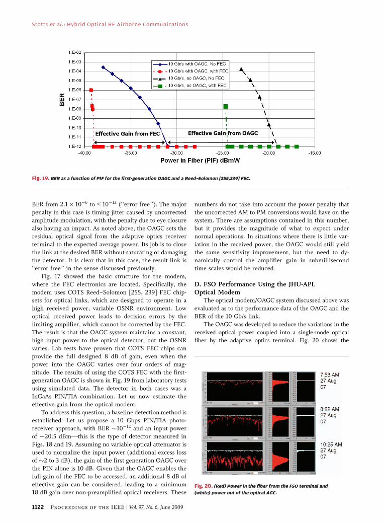
varies. Lab tests have proven that COTS FEC chips can
provide the full designed 8 dB of gain, even when thepower into the OAGC varies over four orders of mag-
nitude. The results of using the COTS FEC with the first-
generation OAGC is shown in Fig. 19 from laboratory tests
using simulated data. The detector in both cases was a
InGaAs PIN/TIA combination. Let us now estimate the
effective gain from the optical modem.
To address this question, a baseline detection method is
established. Let us propose a 10 Gbps PIN/TIA photo-receiver approach, with BER �10�12 and an input power
of �20.5 dBmVthis is the type of detector measured in
Figs. 18 and 19. Assuming no variable optical attenuator is
used to normalize the input power (additional excess loss
of �2 to 3 dB), the gain of the first generation OAGC over
the PIN alone is 10 dB. Given that the OAGC enables the
full gain of the FEC to be accessed, an additional 8 dB of
effective gain can be considered, leading to a minimum18 dB gain over non-preamplified optical receivers. These
numbers do not take into account the power penalty that
the uncorrected AM to PM conversions would have on the
system. There are assumptions contained in this number,
but it provides the magnitude of what to expect undernormal operations. In situations where there is little var-
iation in the received power, the OAGC would still yield
the same sensitivity improvement, but the need to dy-
namically control the amplifier gain in submillisecond
time scales would be reduced.
D. FSO Performance Using the JHU-APLOptical Modem
The optical modem/OAGC system discussed above was
evaluated as to the performance data of the OAGC and the
BER of the 10 Gb/s link.
The OAGC was developed to reduce the variations in the
received optical power coupled into a single-mode optical
fiber by the adaptive optics terminal. Fig. 20 shows the
Fig. 19. BER as a function of PIF for the first-generation OAGC and a Reed–Solomon [255,239] FEC.
Fig. 20. (Red) Power in the fiber from the FSO terminal and
(white) power out of the optical AGC.
Stotts et al . : Hybrid Optical RF Airborne Communications
1122 Proceedings of the IEEE | Vol. 97, No. 6, June 2009
variation in the power in the optical link (red trace) and theoutput of the optical AGC (white trace). This is an indication
of the power variation both over the short time frame of each
data frame (1 s) and as the test day progressed. The
degradation of the link that occurred after sunrise is clearly
apparent. The average received power dropped nearly 20 dB,
and the power distribution increased dramatically. This
would increase the amount of errors seen in the communica-
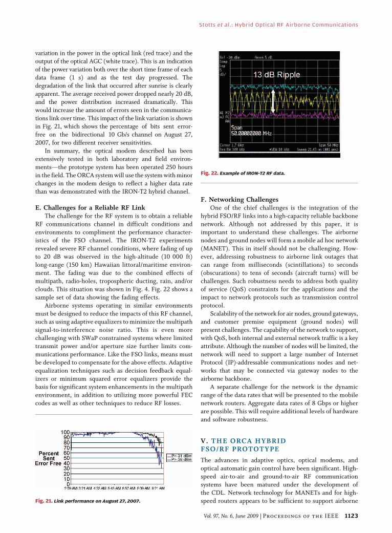
tions link over time. This impact of the link variation is shownin Fig. 21, which shows the percentage of bits sent error-
free on the bidirectional 10 Gb/s channel on August 27,
2007, for two different receiver sensitivities.
In summary, the optical modem described has been
extensively tested in both laboratory and field environ-
mentsVthe prototype system has been operated 250 hours
in the field. The ORCA system will use the system with minor
changes in the modem design to reflect a higher data ratethan was demonstrated with the IRON-T2 hybrid channel.
E. Challenges for a Reliable RF LinkThe challenge for the RF system is to obtain a reliable
RF communications channel in difficult conditions and
environments to compliment the performance character-
istics of the FSO channel. The IRON-T2 experiments
revealed severe RF channel conditions, where fading of upto 20 dB was observed in the high-altitude (10 000 ft)
long-range (150 km) Hawaiian littoral/maritime environ-
ment. The fading was due to the combined effects of
multipath, radio-holes, tropospheric ducting, rain, and/or
clouds. This situation was shown in Fig. 4. Fig. 22 shows a
sample set of data showing the fading effects.
Airborne systems operating in similar environments
must be designed to reduce the impacts of this RF channel,such as using adaptive equalizers to minimize the multipath
signal-to-interference noise ratio. This is even more
challenging with SWaP constrained systems where limited
transmit power and/or aperture size further limits com-
munications performance. Like the FSO links, means must
be developed to compensate for the above effects. Adaptive
equalization techniques such as decision feedback equal-
izers or minimum squared error equalizers provide thebasis for significant system enhancements in the multipath
environment, in addition to utilizing more powerful FEC
codes as well as other techniques to reduce RF losses.
F. Networking ChallengesOne of the chief challenges is the integration of the
hybrid FSO/RF links into a high-capacity reliable backbone
network. Although not addressed by this paper, it isimportant to understand these challenges. The airborne
nodes and ground nodes will form a mobile ad hoc network
(MANET). This in itself should not be challenging. How-
ever, addressing robustness to airborne link outages that
can range from milliseconds (scintillations) to seconds
(obscurations) to tens of seconds (aircraft turns) will be
challenges. Such robustness needs to address both quality
of service (QoS) constraints for the applications and theimpact to network protocols such as transmission control
protocol.
Scalability of the network for air nodes, ground gateways,
and customer premise equipment (ground nodes) will
present challenges. The capability of the network to support,
with QoS, both internal and external network traffic is a key
attribute. Although the number of nodes will be limited, the
network will need to support a large number of InternetProtocol (IP)-addressable communications nodes and net-
works that may be connected via gateway nodes to the
airborne backbone.
A separate challenge for the network is the dynamic
range of the data rates that will be presented to the mobile
network routers. Aggregate data rates of 8 Gbps or higher
are possible. This will require additional levels of hardware
and software robustness.
V. THE ORCA HYBRIDFSO/RF PROTOTYPE
The advances in adaptive optics, optical modems, and
optical automatic gain control have been significant. High-
speed air-to-air and ground-to-air RF communication
systems have been matured under the development ofthe CDL. Network technology for MANETs and for high-
speed routers appears to be sufficient to support airborneFig. 21. Link performance on August 27, 2007.
Fig. 22. Example of IRON-T2 RF data.
Stotts et al . : Hybrid Optical RF Airborne Communications
Vol. 97, No. 6, June 2009 | Proceedings of the IEEE 1123
backbone networks. The IRON-T2 experiments have
shown that an integrated hybrid communications system
is feasible, but the reliability of such a system still needs to
be addressed.
As noted earlier in this paper, DARPA is proceeding
with the next level of development through the initiationof the ORCA program. The intent of the ORCA program is
to design, build, and test a secure, IP, hybrid electrooptical
and radio-frequency backbone network for tactical reach-
back and data dissemination applications, as well as to
provide a demonstration of technologies for hybrid FSO/
RF networking between ground sites. In particular, the
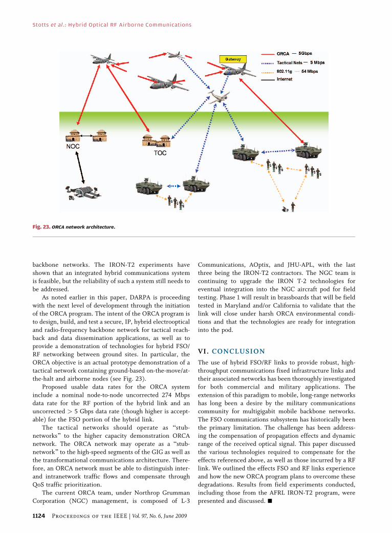
ORCA objective is an actual prototype demonstration of a
tactical network containing ground-based on-the-move/at-the-halt and airborne nodes (see Fig. 23).
Proposed usable data rates for the ORCA system
include a nominal node-to-node uncorrected 274 Mbps
data rate for the RF portion of the hybrid link and an
uncorrected > 5 Gbps data rate (though higher is accept-
able) for the FSO portion of the hybrid link.
The tactical networks should operate as Bstub-
networks[ to the higher capacity demonstration ORCAnetwork. The ORCA network may operate as a Bstub-
network[ to the high-speed segments of the GIG as well as
the transformational communications architecture. There-
fore, an ORCA network must be able to distinguish inter-
and intranetwork traffic flows and compensate through
QoS traffic prioritization.
The current ORCA team, under Northrop Grumman
Corporation (NGC) management, is composed of L-3
Communications, AOptix, and JHU-APL, with the last
three being the IRON-T2 contractors. The NGC team is
continuing to upgrade the IRON T-2 technologies for
eventual integration into the NGC aircraft pod for field
testing. Phase 1 will result in brassboards that will be field
tested in Maryland and/or California to validate that thelink will close under harsh ORCA environmental condi-
tions and that the technologies are ready for integration
into the pod.
VI. CONCLUSION
The use of hybrid FSO/RF links to provide robust, high-
throughput communications fixed infrastructure links andtheir associated networks has been thoroughly investigated
for both commercial and military applications. The
extension of this paradigm to mobile, long-range networks
has long been a desire by the military communications
community for multigigabit mobile backbone networks.
The FSO communications subsystem has historically been
the primary limitation. The challenge has been address-
ing the compensation of propagation effects and dynamicrange of the received optical signal. This paper discussed
the various technologies required to compensate for the
effects referenced above, as well as those incurred by a RF
link. We outlined the effects FSO and RF links experience
and how the new ORCA program plans to overcome these
degradations. Results from field experiments conducted,
including those from the AFRL IRON-T2 program, were
presented and discussed. h
Fig. 23. ORCA network architecture.
Stotts et al . : Hybrid Optical RF Airborne Communications
1124 Proceedings of the IEEE | Vol. 97, No. 6, June 2009
RE FERENCES
[1] L. Joe and I. Porche, III, BFuture Armybandwidth needs and capabilities,[RAND Corp., 2004.
[2] R. Boland, BInnovators imaginecommunications far down the road,[Signal Mag. Online, Jun. 2008.
[3] L. Stotts, G. Lee, and B. Stadler, BFree spaceoptical communications: Coming of age,[ inProc. SPIE Conf. Atmos. Propag. V,G. C. Gilbreath and L. M. Wasiczko, Eds.,Apr. 18, 2008.
[4] C. G. Welles et al., BHAVE LACEVFinalreport for period January 1984–March 1986,’’AFWAL-TR-86-1102.
[5] R. Feldmann and S. Rogers, BAirborne lasercommunications scintillation measurementsand model: Comparison of results,[ inProc. 10th Int. Conf. Lasers Applicat.(Lasers 87), Lake Tahoe, NV, Dec. 7–11, 1987.
[6] R. J. Feldmann and R. A. Gill, BDevelopmentof laser crosslink for airborne operations,[ inProc. Military Communications Conf. 1998(MILCOM 98), Oct. 18–21, 1998, vol. 2,pp. 633–637.
[7] M. Gangle, D. Fisher et al., BAirborne lasercommunication terminal for intelligence,surveillance, and reconnaissance,[ in Proc.SPIE Free Space Laser Commun. IV, vol. 5550,J. Ricklin and D. G. Voelz, Eds., 2004,vol. 5550, pp. 92–103.
[8] L. Stotts, B. Stadler, B. Graves, M. Northcottet al., BOptical RF communications adjunct,[in Proc. SPIE Conf. Free-Space Laser Commun.VIII, vol. 7091, A. K. Majumdar and C. Davis,Eds., Aug. 10–12, 2008, vol. 7091.
[9] L. Stotts, BStrategic laser communicationsprogram,[ in Proc. NAVY/DARPA 4th Tech.Interchange Meeting, 1979, vol. I, NOSC Tech.Doc. TD 352, p 1.
[10] L. Stotts, BStrategic blue-green submarinecommunications systems (U),[ in Proc. SPIEOcean Optics IV Conf. (Classified Session),Monterey, CA, 1979, Naval PostgraduateSchool.
[11] L. Stotts, BStrategic laser communications andits requisite technology options,[ in Proc. 2ndAnnu. Conf. Electro-Opt. Syst. Technol.,Los Angeles, CA, 1980, p. 13-1.
[12] L. Stotts and P. Titterton, BLink models forspace-and air-to-subsurface optical
communications analysis,[ in Proc. Int.Telemeter. Conf., Los Angeles, CA, 1980.
[13] L. Stotts and R. Munn, BTactical airbornelaser communications,[ in Proc. Conf. Laserand Electro-Optics, San Diego, CA,Nov. 6–7, 1990.
[14] L. Stotts and R. Munn, BTactical airbornelaser communications,[ in Proc. CommonDefense 1990, Washington, D.C.,Nov. 27–29, 1990.
[15] A. Majumdar and J. Ricklin, BFree space lasercommunications: Principles and advances,[in Optical and Fiber Communications.New York: Springer Science/Business Media,2008.
[16] S. G. Lambert and W. L. Casey,Laser Communications in Space. Boston, MA:Artech, 1995.
[17] A. Majumdar, BLaboratory-simulationexperiment for optical communicationsthrough low-visibility atmosphere using adiode laser,[ IEEE J. Quantum Electron.,vol. QE-21, p. 919, 1984.
[18] A. Majumdar, BOptical communicationsbetween aircraft in low-visibility atmosphereusing a diode laser,[ Appl. Opt., vol. 24, no. 21,pp. 3659–3665, 1985.
[19] S. Karp, R. Gagliardi, S. Moran, and L. Stotts,Optical Channels. New York: Plenum, 1988.
[20] R. Gagliardi and S. Karp, OpticalCommunications. Malabar, FL: Krieger,1988.
[21] J. Kahn and J. Barry, BWireless infraredcommunications,[ Proc. IEEE, vol. 85, no. 3,pp. 265–298, 1997.
[22] D. Caplan, B. Robinson, M. Stevens,D. Boroson, and S. Hamilton, BHigh-ratephoton-efficient laser communications withnear single-photon/bi receiver sensitivity,[ inProc. Opt. Fiber Conf. (OFC), 2006.
[23] I. Kim, B. McArthur, and E. Korevaar,BComparison of laser beam propagation at785 nm and 1550 nm in fog and haze foroptical wireless communications,[ inProc. SPIE Opt. Wireless Commun. III,E. J. Korevaar, Ed., 2000, vol. 4214,pp. 26–37.
[24] B. R. Strickland, M. J. Lavan, E. Woodbridge,and V. Chan, BEffects of fog on the bit-errorrate of a free space laser communicationssystem,[ Appl. Opt., vol. 38, pp. 414–431,1999.
[25] W. S. Ross, W. P. Jaeger, J. Nakai,T. T. Nguyen, and J. H. Shapiro,BAtmospheric optical propagationVAnintegrated approach,[ Opt. Eng., vol. 21,p. 775, 1982.
[26] J. Ricklin and F. Dadidson, BAtmosphericturbulence effects on a partially coherentGaussian beam: Implications for free-spacelaser communications,[ J. Opt. Soc. Amer.,vol. 69, no. 1, pp. 199–202, 2002.
[27] J. Ricklin, S. Bucaille, and F. Davidson,BPerformance loss factors for opticalcommunications through clear airturbulence,[ in Proc. SPIE, 2003, vol. 5160,pp. 1–12.
[28] M. Borrello, BA multi-stage PointingAcquisition and Tracking (PAT) controlsystem approach for air-to-air lasercommunications,[ in Proc. 2005 Amer. Contr.Conference, Jun. 8–10, 2005, pp. 3975–3980.
[29] D. Caplan, BHigh-performance free-spacelaser communications and future trends,[ inProc. Opt. Amplifiers Applicat. (LAA’05) TopicalMeeting, Budapest, Hungary, 2005.
[30] H. Haus, BLimits on communications usingphotons,[ in Proc. MIT-EECS Colloq. Series,1997.
[31] M. Northcott, A. McClaren, J. Graves et al.,BLong distance laser communicationsdemonstration,[ in Proc. SPIE Conf. DefenseTransform. Net-Centric Syst. 2007,R. Suresh, Ed., May 1, 2007, vol. 6578.
[32] D. Young, J. Sluz, J. Juarez, M. Airola, R. Sova,H. Hurt, M. Northcott, J. Phillips,A. McClaren, D. Driver, D. Abelson, andJ. Foshee, BDemonstration of high data ratewavelength division multiplexed transmissionover a 150 km free space optical link,[ inProc. SPIE Defense Transform. Net-Centric Syst.,May 2, 2007, vol. 6578.
[33] D. Young, J. Sluz, J. Juarez et al.,BDemonstration of high data rate wavelengthdivision multiplexed transmission over a150 km free space optical link,[ in Proc. IEEEMilitary Commun. Conf. (MILCOM 2007),Oct. 29–31, 2007, pp. 1–6.
[34] M. Northcott, A. McClaren, J. Graves,J. Phillips et al., BLong distance lasercommunications demonstration,[ in Proc.SPIE Defense Transform. Net-Centric Syst.,R. Suresh, Ed., 2007, vol. 6578, p. 65780S.
ABOUT T HE AUTHO RS
Larry B. Stotts (Fellow, IEEE) received the
B.A. degree in applied physics and information
sciences and the Ph.D. degree in electrical engi-
neering (communications systems) from the
University of California at San Diego.
He is Deputy Director for the Strategic Tech-
nology Office, Defense Advanced Research Agency
(DARPA). He support the Director in guiding and
directing a team of program managers developing
communications, networking, information opera-
tions and battle command technologies for network-centric operations
(warfare and enterprise) and generalized C4ISR. Prior to joining DARPA,
he was Director for Technology in the Office of the Assistant Secretary of
the Army for Acquisition, Logistics and Technology from 1999 to 2002.
From 1996 to 1999, he was Chief Scientific and Technical Advisor and the
Integrated Product Team Leader for Aircraft, Avionics and Navigation
Systems in the Office for Communications, Navigation and Surveillance
Systems Department, Federal Aviation Administration. From 1987 to
1996, he was a Program Manager and then Assistant Director for Special
Projects, Tactical Technology Office, DARPA. From 1971 to 1987, he was
the Associate for Image Processing with the Naval Ocean Systems Center
(NOSC). He has published 85 journal articles, conference papers, and
technical reports. He is a coauthor of Optical Channels: Fiber, Atmo-
sphere, Water and Clouds (New York: Plenum, 1988) and the BOcean
Optical Propagation[ entry in the SPIE Encyclopedia of Optical Engineering.
He has received seven U.S. patents.
Dr. Stotts is a Fellow of the Society of Photographic and Instrumen-
tation Engineers (SPIE) and a member of numerous professional
societies. He received a DARPA Technical Achievement Award for his
management of the Future Combat Systems Communications Program
in 2006. He received a National Partnership in Reinventing Government
as part of the Maritime Differential Global Positioning System (GPS)
Service Team and the Nationwide GPS Service Team in 1999. He
received the Secretary of Defense Medal for Meritorious Civilian Service
in 1991 and 1996. He received the Technical Cooperation Program
Technical Achievement Award in 1991; the NOSC Technical Director’s
Award in 1986; and the DARPA Outstanding Technical Achievement
Award in 1985.
Stotts et al . : Hybrid Optical RF Airborne Communications
Vol. 97, No. 6, June 2009 | Proceedings of the IEEE 1125
Larry C. Andrews (Senior Member, IEEE) re-
ceived the doctoral degree in theoretical me-
chanics from Michigan State University, East
Lansing, in 1970.
He is a Professor of mathematics at the
University of Central Florida, Orlando, and an
Associate Member of the College of Optics/CREOL.
He is an Associate Member of the Florida Space
Institute. Previously, he held a Faculty position at
Tri-State University and was a Staff Mathematician
with the Magnavox Company, antisubmarine warfare operation. He has
been an active researcher in optical wave propagation through random
media for more than 25 years and is the author or coauthor of ten
textbooks on the topics of differential equations, boundary value
problems, special functions, integral transforms, wave propagation
through random media, and mathematical techniques for engineers.
Along with wave propagation through random media, his research
interests include special functions, random variables, atmospheric
turbulence, and signal processing.
Paul C. Cherry (Member, IEEE) received the
B.S.E.E. degree from the University of Colorado,
Boulder, in 1986 and the M.S.E.E. and Ph.D. degrees
from the University of Utah, Salt Lake City, in 1992
and 1996, respectively.
His doctoral research was in electromagnetics.
From 1986 to 1996, he was an RF/Microwave
Engineer with Unisys and Loral (now L-3 Commu-
nications, CS-W), Salt Lake City. From 1996 to
2003, he was with Thomson Consumer Electron-
ics, Indianapolis, IN, first in their Satellite Receivers Group and then in
their Advanced Communications Group. He returned to L-3 Communica-
tions in 2003, where he worked in the Advanced Communications Group
and is currently a Systems Engineer focusing on high-rate RF networked
and hybrid RF/FSO communications systems and technologies.
James J. Foshee (Member, IEEE) received the master’s degree in
systems engineering and in business administration from Wright State
University, Dayton, OH.
He is a Development Engineer with the Connectivity Branch,
Information Directorate, Air Force Avionics Laboratory. He is involved
in the development of wireless data links (RF, optical, and combined RF/
optical) for the transfer of high-capacity high-value data. His past
experience includes the development of airborne/ground satellite
communications terminals, communications propagation research,
and communications technologies flight testing. He has authored/
coauthored/presented papers in a range of related technology areas.
He developed, demonstrated, and patented a bit timing extraction (clock)
technique for use in a noisy satellite communications link disturbed by
ionospheric scintillation. He worked with the Defense Advanced Projects
Agency in the initial development of the Tactical Common Data Link
family of terminals and in the initial development of an airborne
communications node, and was involved in the initial development of the
payload communications package during the Predator UAV develop-
ment. He is presently involved in developing data links for the Angel Fire
program (small surveillance aircraft presently deployed in Iraq),
developing the communications payload and ground terminal for the
TACSAT-3 satellite system (a LEO satellite with a sensor package),
accomplishing research in optical and communications technologies
(Lasercomm and RF data link terminal technologies and optical and RF
devices), and providing support to the Missile Defense Agency in their
SBIR/STTR programs to support insertion into BMDS systems.
Mr. Foshee is a registered Professional Engineer in the State of Ohio.
Paul J. Kolodzy (Senior Member, IEEE) received
the B.S. degree in chemical engineering from
Purdue University, West Lafayette, IN. He re-
ceived the M.S. degree in chemical engineering
and the Ph.D. degree from Case Western Reserve
University, Cleveland, OH.
He is a Communications Technology Consultant
in advanced wireless and networking technology.
He has 20 years of experience in technology
development for advanced communications, net-
working, electronic warfare, and spectrum policy. He was Director of the
Center for Wireless Network Security (WiNSeC), Stevens Institute of
Technology; Senior Spectrum Policy Advisor with the Federal Commu-
nications Commission and Director of Spectrum Policy Task Force;
Program Manager with the Defense Advanced Projects Agency; Director
of Signal Processing and Strategic Initiatives with Sanders, a Lockheed
Martin Company; and with MIT Lincoln Laboratory.
William K. McIntire received the engineering
degree from South Dakota School of Mines and
Technology, Rapid City, in 1978.
He spent two years in the Peace Corps prior to
beginning his engineering career. He is currently
with L-3 Communications. He has 20 years of
experience with wide-band microwave digital data
links used for air-to-air, air-to-surface, and air-to-
satellite communications. His past work includes
airborne and surface terminals for DSCS, INTELSAT,
TDRS, and MILSTAR satellites. Currently, he is leading a design team for a
waveform and supporting modem that enables high-data-rate communica-
tions using a radar system as the aperture.
Malcolm Northcott received the B.A. degree in
physics from Christ’s College, Cambridge, U.K., in
1984 and the Ph.D. degree in optics from Imperial
College London, U.K., in 1988.
He is Founder and Vice President of Optics
Software. He is a pioneer in the development of
software for adaptive optics (AO) systems, He has
18 years of experience in adaptive optics based
product development, adaptive optics for astron-
omy, software development, and optical system
modeling. He played a key role in the development of curvature-sensing
AO technology and participated in the construction of the world’s first
curvature-sensing AO system for the Canada-France-Hawaii telescope in
Hawaii. Along with designing the computer control system, including the
architecture of the custom electronics, he wrote all of the software
necessary to operate the system. He contributed to the construction of
AO systems for the NASA IRTF and Mess Solar observatories. He has
continued to work to improve the Gemini North telescope, also based in
Hawaii. Prior to founding AOptix, he was an Astronomer at the University
of Hawaii and Imperial College London. He was with the Institute for
Astronom, University of Hawaii, from 1989 to 1999, where he conducted
research on adaptive optics. He has received eight U.S. patents.
Stotts et al . : Hybrid Optical RF Airborne Communications
1126 Proceedings of the IEEE | Vol. 97, No. 6, June 2009
Ronald L. Phillips (Senior Member, IEEE) has
received four degrees in the areas of electrical
engineering and mathematics. He received the
doctoral degree in electrical engineering from
Arizona State University, Tempe, in 1971.
He was Founding Director of the Florida Space
Institute, Kennedy Space Center, University of
Central Florida (UCF), Orlando, started in 1996.
He also was Founding Director, in 1984, of UCF’s
optics center CREOL, which went on to become the
country’s first university stand-alone college in the field of optical
physics, engineering, and photonics. His academic positions at UCF
include Professor in the School of Electrical Engineering and Computer
Science, Professor of the Department of Mathematics, and Professor of
the College of Optics and Photonics. He has held academic positions on
the Faculties of Arizona State University and the University of California,
San Diego. He has been an active researcher in wave propagation
through random media for more than 35 years. He is the coauthor of
three research books on the topic of wave propagation through random
media and applications to laser communications and radar. He is also
coauthor of a text on advanced applied mathematics. In addition to
optical wave propagation, his research interests include optical space
communications, laser radar, imaging through atmospheric turbulence,
and random processes.
Dr. Phillips is a Fellow of OSA, SPIE, and AIAA. His honors and awards
include: the National Science Foundation’s NATO Postdoctoral Fellow
and ASEE’s Outstanding Contributions to Research for all fields of
university engineering research.
H. Alan Pike received the B.A. degree from the
Massachusetts Institute of Technology, Cambridge,
in electrical science and engineering and the
Ph.D. degree in optics (with a specialty in quantum
electronics) from the Institute of Optics, University
of Rochester, Rochester, NY.
He is President of Defense Strategies & Sys-
tems Inc., a small business specializing in system
architecture and system engineering for defense
related applications. He has extensive experience
in designing, developing, and operating advanced technology ground,
air, and space systems. He has published widely on subjects including
aerospace testing, strategic defense, optical discrimination, and devel-
opment and testing of laser weapon components. He is well known in the
field of lasers propagation. He led the team that first demonstrated
adaptive optical compensation for high-power laser distortions produced
by thermal blooming of a Bmegawatt class[ CW laser. His thesis, BOrganic
Dye Lasers,[ incorporated both theoretical and experimental advances
leading to the first tunable single-mode dye laser, now a model for
commercially available tunable lasers.
Brian Stadler received the bachelor’s degree in
aerospace engineering from the University of
Cincinnati, Cincinnati, OH, and the master’s degree
in systems engineering from Wright State Univer-
sity, Dayton, OH.
He is a Research Engineer and Program Man-
ager in the Electro-Optical Combat ID Technology
Branch, Sensors Directorate, Air Force Research
Laboratory (AFRL), Wright-Patterson AFB, OH. He
is currently the Defense Advanced Research
Project Agency (DARPA) Technical Agent for the DARPA Optical RF
Communications Adjunct Program. Previously, he was a Technical Agent
for various DARPA efforts related to free-space optical communications
and hybrid RF and FSO communications, including the Optical RF
Combined Link Experiment (ORCLE) and Terra Hertz Operational Reach-
back (THOR) programs. Prior to working in the Sensors Directorate, he
was with the Air Vehicles Directorate of AFRL, assessing directed energy
integration issues on aircraft and conducted utility studies of both high
power microwave and high energy laser weapons. He also conducted a
wide variety of advanced technology and flight control simulations using
the Air Vehicle Directorate’s high-fidelity real-time man-in-the-loop
facility at Wright-Patterson AFB.
David W. Young (Senior Member, IEEE) received
the B.S. degree in physics and the M.S. and Ph.D.
degrees in electrical engineering from the Univer-
sity of Connecticut, Storrs.
He is currently a member of Senior Principal
Staff at the Applied Physics Laboratory, The Johns
Hopkins University, Laurel, MD. His current work is
on high-bandwidth free-space optical communica-
tions systems development, focusing on systems
and technologies for enabling robust links in high
dynamic range environments. He has designed, built, and field demon-
strated high channel count multigigabit/second wavelength-division
multiplexed (WDM) free-space optical communication equipment. He
was an early developer of wavelength agile dense WDM ultra-long-haul
systems while with Corvis Corporation.
Stotts et al . : Hybrid Optical RF Airborne Communications
Vol. 97, No. 6, June 2009 | Proceedings of the IEEE 1127