How to Build a CAN
Last Update 2007.05.27
1.0.0
Copyright 2000-2007 Kenneth M. Chipps PhD www.chipps.com
1

Objectives of This Section
• Learn– What a CAN looks like in general– This does not include every single detail, just
the general approach to take to build such a thing
– The rest of the details are in other presentations
Copyright 2000-2007 Kenneth M. Chipps PhD www.chipps.com 2
What is a CAN
• A CAN – Campus Area Network connects multiple networks with easy walking distance of each other
• Let’s look at three examples of what would constitute a CAN
• Then we’ll look at the specific equipment required to setup a CAN
Copyright 2000-2007 Kenneth M. Chipps PhD www.chipps.com 3

What Does a CAN Look Like
• The simplest CAN just connects two buildings horizontally
• Think of this view as being from above
Copyright 2000-2007 Kenneth M. Chipps PhD www.chipps.com 4
Building A Building B
Cable

What Does a CAN Look Like
• In this example the most common way to connect the two buildings is to use fiber optic cable run underground from an entry point in each building
• Inside each building the fiber is run from the exterior wall through the air space above the ceiling to the LAN room just like any other cabling
Copyright 2000-2007 Kenneth M. Chipps PhD www.chipps.com 5
What Does a CAN Look Like
• In the LAN room the fiber is connected into the LAN through a switch port
Copyright 2000-2007 Kenneth M. Chipps PhD www.chipps.com 6

What Equipment is Required
• For this simple two location CAN let’s look at an equipment list from a Siecor catalog
• Siecor is a company that makes the parts required to create such a thing, as do many other companies
• Siecor is now part of Corning Cable Systems
• This is just an example of one way to do this
Copyright 2000-2007 Kenneth M. Chipps PhD www.chipps.com 7
What Equipment is RequiredLocation Quantit
yPart Number Description
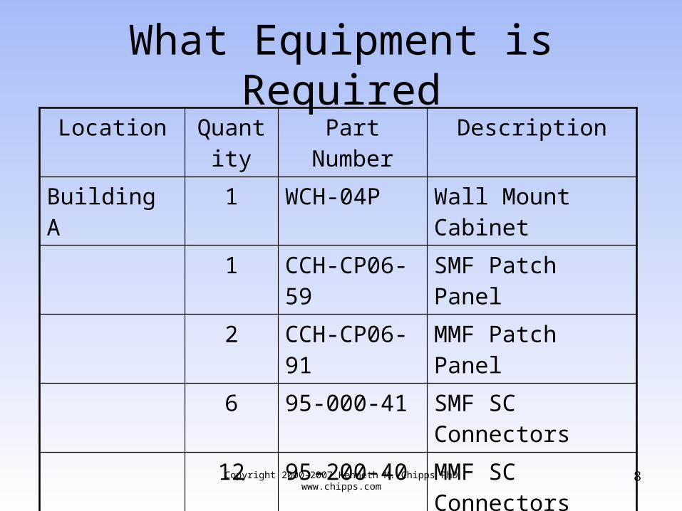
Building A 1 WCH-04P Wall Mount Cabinet
1 CCH-CP06-59 SMF Patch Panel
2 CCH-CP06-91 MMF Patch Panel
6 95-000-41 SMF SC Connectors
12 95-200-40 MMF SC Connectors
Copyright 2000-2007 Kenneth M. Chipps PhD www.chipps.com 8

What Equipment is RequiredLocation Quantit
yPart Number Description
Underground How ever many meters of fiber as are required
018XW4-AI420A20 Altos Loose Tube Fiber Optic Cable with 12 MMF and 6 SMF
Copyright 2000-2007 Kenneth M. Chipps PhD www.chipps.com 9

What Equipment is RequiredLocation Quantit
yPart Number Description
Building B 1 WCH-04P Wall Mount Cabinet
1 CCH-CP06-59 SMF Patch Panel
2 CCH-CP06-91 MMF Patch Panel
6 95-000-41 SMF SC Connectors
12 95-200-40 MMF SC Connectors
Copyright 2000-2007 Kenneth M. Chipps PhD www.chipps.com 10

What Equipment is Required
• Let’s look at some pictures of these parts as provided by the Corning web site
Copyright 2000-2007 Kenneth M. Chipps PhD www.chipps.com 11

What Equipment is Required
• Wall Mount Cabinet - WCH-04P
Copyright 2000-2007 Kenneth M. Chipps PhD www.chipps.com 12

What Equipment is Required
• SMF Patch Panel which mounts in the cabinet on the right side where the ovals are shown - CCH-CP06-59
Copyright 2000-2007 Kenneth M. Chipps PhD www.chipps.com 13

What Equipment is Required
• MMF Patch Panel which mounts in the cabinet on the right side where the ovals are shown – CCH-CP06-91
Copyright 2000-2007 Kenneth M. Chipps PhD www.chipps.com 14
What Equipment is Required
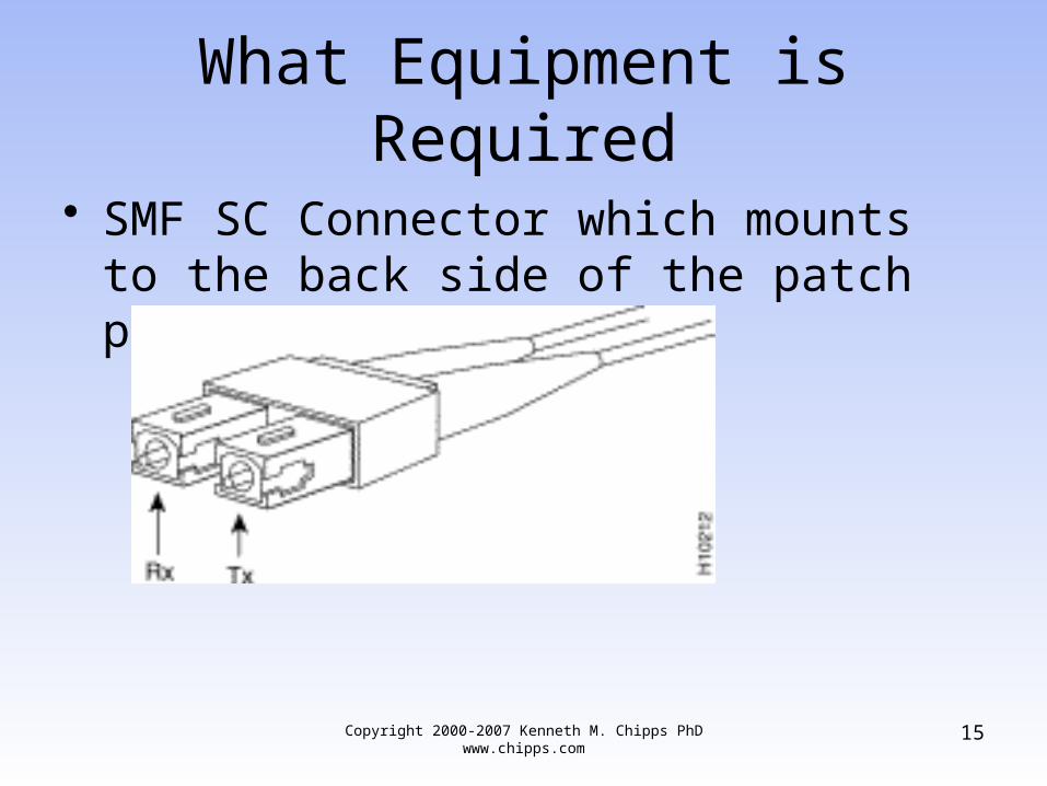
• SMF SC Connector which mounts to the back side of the patch panel – 95-200-41
Copyright 2000-2007 Kenneth M. Chipps PhD www.chipps.com 15

What Equipment is Required
• MMF SC Connector which mounts to the back side of the patch panel – 95-000-40
Copyright 2000-2007 Kenneth M. Chipps PhD www.chipps.com 16
What Equipment is Required
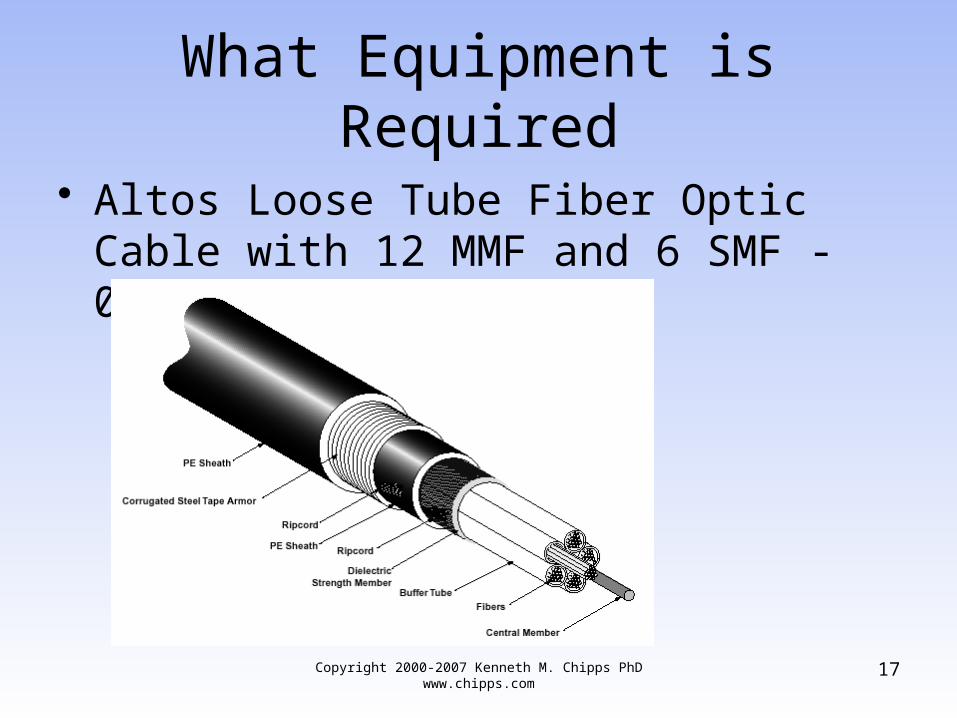
• Altos Loose Tube Fiber Optic Cable with 12 MMF and 6 SMF - 018XW4-AI420A20
Copyright 2000-2007 Kenneth M. Chipps PhD www.chipps.com 17
What Equipment is Required
• The parts shown here all mount to a wall• The same thing can be done using a relay
rack, which is attached to the floor, and patch panels of the same sort that mount to the relay rack, instead of to a cabinet as shown above
• The parts that connect to this hardware just discussed, like switches are discussed after the next example of a somewhat more complex CAN
Copyright 2000-2007 Kenneth M. Chipps PhD www.chipps.com 18

What Does a CAN Look Like
• A more complex CAN would still connect horizontally but connect more than just two buildings
Copyright 2000-2007 Kenneth M. Chipps PhD www.chipps.com 19
Building C
Building B
Building D
Building A

What Does a CAN Look Like
• In this example four buildings are connected using fiber optic cable run underground from an entry point in each building to a single building
• A CAN is wired just like a LAN, in other words in a star pattern
Copyright 2000-2007 Kenneth M. Chipps PhD www.chipps.com 20

What Does a CAN Look Like
• Inside each building the fiber is run from the exterior wall through the air space above the ceiling to the LAN room just like any other cabling
• In the LAN room the fiber is connected into the LAN through a switch port
Copyright 2000-2007 Kenneth M. Chipps PhD www.chipps.com 21

What Does a CAN Look Like
• As discussed above a CAN usually connects physically separate buildings by installing cable horizontally
• However if you are connecting floors in a single building vertically, when does the distance make this a vertical CAN instead of a backbone
• Who knows, doesn’t really matter
Copyright 2000-2007 Kenneth M. Chipps PhD www.chipps.com 22

What Does a CAN Look Like
• Just keep in mind that the techniques used to make horizontal connections can be run vertically as well
Copyright 2000-2007 Kenneth M. Chipps PhD www.chipps.com 23

What Does a CAN Look Like
Copyright 2000-2007 Kenneth M. Chipps PhD www.chipps.com 24

What Equipment is Required
• The first thing used is a cable to connect the sites
• It does not matter whether it is one site or several sites
• Once the cable is in place the next step is to connect it to the equipment at each site
• What kind of equipment depends on what the rest of the network will look like
Copyright 2000-2007 Kenneth M. Chipps PhD www.chipps.com 25

What Equipment is Required
• Some examples are mentioned next• Do not rely on the equipment mentioned
specifically, since they are just for illustration purposes
• The exact manufacturer and model is not as important as the concepts discussed
Copyright 2000-2007 Kenneth M. Chipps PhD www.chipps.com 26

What Equipment is Required
• In general for a simple CAN an Ethernet Layer 2 switch is used
• An example of this type of switch suitable for an average size LAN in each building who have users who need to share with the other building or just talk to users in the other building would be a Cisco Catalyst 2900
Copyright 2000-2007 Kenneth M. Chipps PhD www.chipps.com 27
What Equipment is Required
• The only other question is what type of fiber to use and therefore what type of fiber port is required in the switch
• This question is answered by looking at the distance between locations and the capacity or speed required for the connection
• Gigabit – 1000 Mbps – Ethernet is the usual choice
Copyright 2000-2007 Kenneth M. Chipps PhD www.chipps.com 28

What Equipment is Required
• 1000BaseSX – Short Wave Length– Uses a short wave length laser - 850 nm -
usually over multimode fiber optic cable– Using 62.5 um multimode the distance limit is
220 to 275 m– Using 50 um multimode the distance is 500 to
550 m
Copyright 2000-2007 Kenneth M. Chipps PhD www.chipps.com 29

What Equipment is Required
• 1000BaseLX – Long Wave Length– Uses a long wavelength laser - 1,300 nm -
over multimode or single mode fiber optic cable
– Over 62.5 um multimode fiber the distance is 550 m
– Over 50 um multimode fiber the distance is 500 m
Copyright 2000-2007 Kenneth M. Chipps PhD www.chipps.com 30

What Equipment is Required
• Of course this is a flat design and does not scale well
• Since the use of layer 2 switches puts all of the devices in the same broadcast domain and a single IP subnet
• Another advantage to a layer 2 switch is it requires no configuration, such as a router does
Copyright 2000-2007 Kenneth M. Chipps PhD www.chipps.com 31

What Equipment is Required
• If the campus or traffic over the links grows this can be changed to a hierarchical design by just changing the model of the switch to one that operates at layer 3 or putting a router on each side of the fiber
• To move up the switch would need to be replaced with a switch that can operate at layer 3 and has more fiber ports
Copyright 2000-2007 Kenneth M. Chipps PhD www.chipps.com 32

What Equipment is Required
• For the four building CAN shown above a layer 3 device is called for
• For example a Cisco 3508 XL has 8 fiber ports, which would work for our example site
Copyright 2000-2007 Kenneth M. Chipps PhD www.chipps.com 33

What Equipment is Required
• In this particular switch the front has nothing but slots
• Modules are inserted into these slots• In this case we would need 4 GBIC –
Gigabit Interface ModulesCopyright 2000-2007 Kenneth M. Chipps PhD www.chipps.com 34

What Equipment is Required
• 3 of the GBIC modules would connect to the fiber coming in from the other three buildings
Copyright 2000-2007 Kenneth M. Chipps PhD www.chipps.com 35

What Equipment is Required
• The fourth GBIC module would connect to a layer 2 switch that would contain the copper ports used to connect the LAN in each building to the CAN for all of the buildings
• Another model Cisco Catalyst 2900 for example
Copyright 2000-2007 Kenneth M. Chipps PhD www.chipps.com 36

What Equipment is Required
• The servers and workstations are then plugged into the copper RJ-45 ports shown along the bottom of the switch
Copyright 2000-2007 Kenneth M. Chipps PhD www.chipps.com 37

Review
• What is a CAN
Copyright 2000-2007 Kenneth M. Chipps PhD www.chipps.com 38