SH(NA)030041ENG-L(1803)MEE Printed in Japan Specifications are subject to change without notice.This Instruction Manual uses recycled paper.
MODEL
MODELCODE
General-Purpose AC Servo
L
SE
RV
O M
OT
OR
INS
TR
UC
TIO
N M
AN
UA
L (V
ol.2)
MOTOR INSTRUCTION(VOL.2)
1CW951
HEAD OFFICE: TOKYO BLDG MARUNOUCHI TOKYO 100-8310
MODEL
HF-MPHF-KPHF-SPHA-LPHC-RPHC-UPHC-LPHF-JPHG-AKSERVO MOTOR INSTRUCTION MANUAL (Vol.2)
L

A - 1
Safety Instructions Please read the instructions carefully before using the equipment.
To use the equipment correctly, do not attempt to install, operate, maintain, or inspect the equipment until you
have read through this Instruction Manual, Installation guide, Servo motor Instruction Manual (Vol. 2) and
appended documents carefully. Do not use the servo amplifier and servo motor until you have a full knowledge
of the equipment, safety information and instructions.
In this Instruction Manual, the safety instruction levels are classified into "WARNING" and "CAUTION".
WARNING Indicates that incorrect handling may cause hazardous conditions,
resulting in death or severe injury.
CAUTION Indicates that incorrect handling may cause hazardous conditions,
resulting in medium or slight injury to personnel or may cause physical damage.
Note that the CAUTION level may lead to a serious consequence according to conditions. Please follow the
instructions of both levels because they are important to personnel safety.
What must not be done and what must be done are indicated by the following diagrammatic symbols.
: Indicates what must not be done. For example, "No Fire" is indicated by .
: Indicates what must be done. For example, grounding is indicated by .
In this Instruction Manual, instructions at a lower level than the above, instructions for other functions, and so
on are classified into "POINT".
After reading this Instruction Manual, keep it accessible to the operator.
A - 2
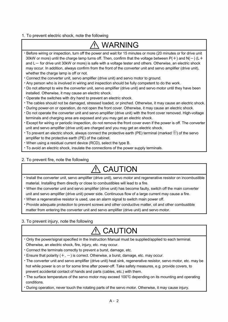
1. To prevent electric shock, note the following
WARNING Before wiring or inspection, turn off the power and wait for 15 minutes or more (20 minutes or for drive unit 30kW or more) until the charge lamp turns off. Then, confirm that the voltage between P( ) and N( ) (L and L for drive unit 30kW or more) is safe with a voltage tester and others. Otherwise, an electric shock may occur. In addition, always confirm from the front of the converter unit and servo amplifier (drive unit), whether the charge lamp is off or not. Connect the converter unit, servo amplifier (drive unit) and servo motor to ground. Any person who is involved in wiring and inspection should be fully competent to do the work. Do not attempt to wire the converter unit, servo amplifier (drive unit) and servo motor until they have been installed. Otherwise, it may cause an electric shock. Operate the switches with dry hand to prevent an electric shock. The cables should not be damaged, stressed loaded, or pinched. Otherwise, it may cause an electric shock. During power-on or operation, do not open the front cover. Otherwise, it may cause an electric shock. Do not operate the converter unit and servo amplifier (drive unit) with the front cover removed. High-voltage terminals and charging area are exposed and you may get an electric shock. Except for wiring or periodic inspection, do not remove the front cover even if the power is off. The converter unit and servo amplifier (drive unit) are charged and you may get an electric shock. To prevent an electric shock, always connect the protective earth (PE) terminal (marked ) of the servo amplifier to the protective earth (PE) of the cabinet. When using a residual current device (RCD), select the type B. To avoid an electric shock, insulate the connections of the power supply terminals.
2. To prevent fire, note the following
CAUTION Install the converter unit, servo amplifier (drive unit), servo motor and regenerative resistor on incombustible
material. Installing them directly or close to combustibles will lead to a fire.
When the converter unit and servo amplifier (drive unit) has become faulty, switch off the main converter
unit and servo amplifier (drive unit) power side. Continuous flow of a large current may cause a fire.
When a regenerative resistor is used, use an alarm signal to switch main power off.
Provide adequate protection to prevent screws and other conductive matter, oil and other combustible
matter from entering the converter unit and servo amplifier (drive unit) and servo motor. 3. To prevent injury, note the following
CAUTION Only the power/signal specified in the Instruction Manual must be supplied/applied to each terminal.
Otherwise, an electric shock, fire, injury, etc. may occur.
Connect the terminals correctly to prevent a burst, damage, etc.
Ensure that polarity ( , ) is correct. Otherwise, a burst, damage, etc. may occur.
The converter unit and servo amplifier (drive unit) heat sink, regenerative resistor, servo motor, etc. may be
hot while power is on or for some time after power-off. Take safety measures, e.g. provide covers, to
prevent accidental contact of hands and parts (cables, etc.) with them.
The surface temperature of the servo motor may exceed 100 depending on its mounting and operating
conditions.
During operation, never touch the rotating parts of the servo motor. Otherwise, it may cause injury.
A - 3
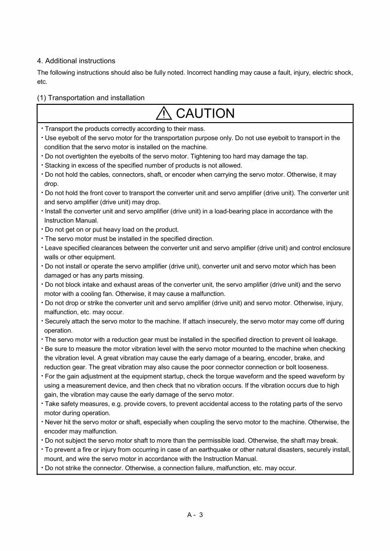
4. Additional instructions
The following instructions should also be fully noted. Incorrect handling may cause a fault, injury, electric shock,
etc. (1) Transportation and installation
CAUTION Transport the products correctly according to their mass.
Use eyebolt of the servo motor for the transportation purpose only. Do not use eyebolt to transport in the
condition that the servo motor is installed on the machine.
Do not overtighten the eyebolts of the servo motor. Tightening too hard may damage the tap.
Stacking in excess of the specified number of products is not allowed.
Do not hold the cables, connectors, shaft, or encoder when carrying the servo motor. Otherwise, it may
drop.
Do not hold the front cover to transport the converter unit and servo amplifier (drive unit). The converter unit
and servo amplifier (drive unit) may drop.
Install the converter unit and servo amplifier (drive unit) in a load-bearing place in accordance with the
Instruction Manual.
Do not get on or put heavy load on the product.
The servo motor must be installed in the specified direction.
Leave specified clearances between the converter unit and servo amplifier (drive unit) and control enclosure
walls or other equipment.
Do not install or operate the servo amplifier (drive unit), converter unit and servo motor which has been
damaged or has any parts missing.
Do not block intake and exhaust areas of the converter unit, the servo amplifier (drive unit) and the servo
motor with a cooling fan. Otherwise, it may cause a malfunction.
Do not drop or strike the converter unit and servo amplifier (drive unit) and servo motor. Otherwise, injury,
malfunction, etc. may occur.
Securely attach the servo motor to the machine. If attach insecurely, the servo motor may come off during
operation.
The servo motor with a reduction gear must be installed in the specified direction to prevent oil leakage.
Be sure to measure the motor vibration level with the servo motor mounted to the machine when checking
the vibration level. A great vibration may cause the early damage of a bearing, encoder, brake, and
reduction gear. The great vibration may also cause the poor connector connection or bolt looseness.
For the gain adjustment at the equipment startup, check the torque waveform and the speed waveform by
using a measurement device, and then check that no vibration occurs. If the vibration occurs due to high
gain, the vibration may cause the early damage of the servo motor.
Take safety measures, e.g. provide covers, to prevent accidental access to the rotating parts of the servo
motor during operation.
Never hit the servo motor or shaft, especially when coupling the servo motor to the machine. Otherwise, the
encoder may malfunction.
Do not subject the servo motor shaft to more than the permissible load. Otherwise, the shaft may break.
To prevent a fire or injury from occurring in case of an earthquake or other natural disasters, securely install,
mount, and wire the servo motor in accordance with the Instruction Manual.
Do not strike the connector. Otherwise, a connection failure, malfunction, etc. may occur.
A - 4
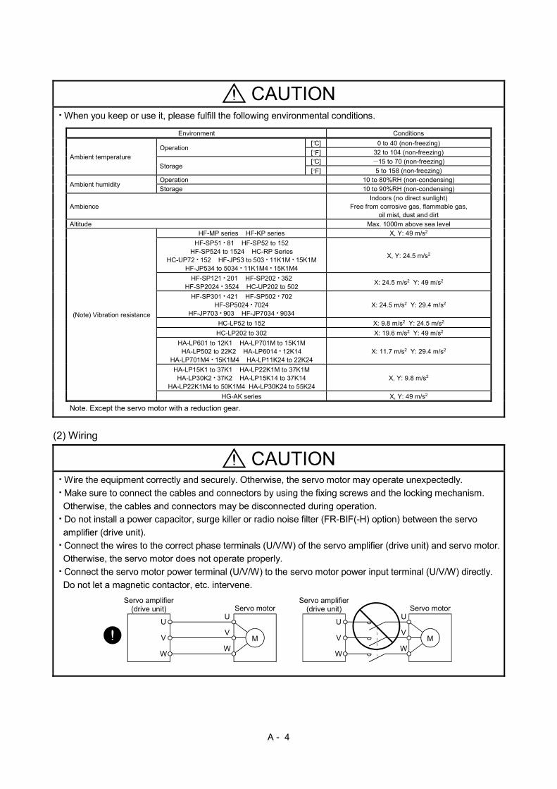
CAUTION When you keep or use it, please fulfill the following environmental conditions.
Environment Conditions
Ambient temperature
Operation [ ] 0 to 40 (non-freezing)
[ ] 32 to 104 (non-freezing)
Storage
[ ] 15 to 70 (non-freezing)
[ ] 5 to 158 (non-freezing)
Ambient humidity
Operation 10 to 80%RH (non-condensing)
Storage 10 to 90%RH (non-condensing)
Ambience
Indoors (no direct sunlight) Free from corrosive gas, flammable gas,
oil mist, dust and dirt
Altitude Max. 1000m above sea level
(Note) Vibration resistance
HF-MP series HF-KP series X, Y: 49 m/s2
HF-SP51 81 HF-SP52 to 152 HF-SP524 to 1524 HC-RP Series
HC-UP72 152 HF-JP53 to 503 11K1M 15K1M HF-JP534 to 5034 11K1M4 15K1M4
X, Y: 24.5 m/s2
HF-SP121 201 HF-SP202 352 HF-SP2024 3524 HC-UP202 to 502
X: 24.5 m/s2 Y: 49 m/s2
HF-SP301 421 HF-SP502 702 HF-SP5024 7024
HF-JP703 903 HF-JP7034 9034 X: 24.5 m/s2 Y: 29.4 m/s2
HC-LP52 to 152 X: 9.8 m/s2 Y: 24.5 m/s2
HC-LP202 to 302 X: 19.6 m/s2 Y: 49 m/s2
HA-LP601 to 12K1 HA-LP701M to 15K1M HA-LP502 to 22K2 HA-LP6014 12K14
HA-LP701M4 15K1M4 HA-LP11K24 to 22K24 X: 11.7 m/s2 Y: 29.4 m/s2
HA-LP15K1 to 37K1 HA-LP22K1M to 37K1M HA-LP30K2 37K2 HA-LP15K14 to 37K14
HA-LP22K1M4 to 50K1M4 HA-LP30K24 to 55K24 X, Y: 9.8 m/s2
HG-AK series X, Y: 49 m/s2
Note. Except the servo motor with a reduction gear. (2) Wiring
CAUTION Wire the equipment correctly and securely. Otherwise, the servo motor may operate unexpectedly.
Make sure to connect the cables and connectors by using the fixing screws and the locking mechanism.
Otherwise, the cables and connectors may be disconnected during operation.
Do not install a power capacitor, surge killer or radio noise filter (FR-BIF(-H) option) between the servo
amplifier (drive unit).
Connect the wires to the correct phase terminals (U/V/W) of the servo amplifier (drive unit) and servo motor.
Otherwise, the servo motor does not operate properly.
Connect the servo motor power terminal (U/V/W) to the servo motor power input terminal (U/V/W) directly.
Do not let a magnetic contactor, etc. intervene.
M
U
V
W
U
Servo motor
MV
W
U
V
W
U
V
W
Servo amplifier(drive unit) Servo motor
Servo amplifier(drive unit)

A - 5
CAUTION Do not connect AC power directly to the servo motor. Otherwise, it may cause a malfunction.
The surge absorbing diode installed to the DC relay for control output should be fitted in the specified
direction. Otherwise, the emergency stop and other protective circuits may not operate.
(The following figure shows the case of the MR-J3- A servo amplifier.)
DOCOM
Control output signal
DICOM
24VDC
Servo amplifier(drive unit)
RA
For sink output interface
DOCOM
Control output signal
DICOM
24VDC
Servo amplifier(drive unit)
RA
For source output interface
When the cable is not tightened enough to the terminal block (connector) of the converter unit and servo
amplifier, the cable or terminal block (connector) may generate heat because of the poor contact. Be sure to
tighten the cable with specified torque.
Configure a circuit to turn off EM2 or EM1 when the power supply is turned off to prevent an unexpected
restart of the servo amplifier (drive unit). (3) Test run adjustment
CAUTION Before operation, check the parameter settings. Improper settings may cause some machines to perform
unexpected operation.
The parameter settings must not be changed excessively. Operation will be unstable. (4) Usage
CAUTION Provide an external emergency stop circuit to ensure that operation can be stopped and power switched off immediately. For equipment in which the moving part of the machine may collide against the load side, install a limit switch or stopper to the end of the moving part. The machine may be damaged due to a collision. Do not scratch the coated surface with hard objects nor clean the coated surface with an organic solvent. Doing so may scuff the surface. Do not disassemble, repair, or modify the product. Otherwise, an electric shock, fire, injury, etc. may occur. Disassembled, repaired, and/or modified products are not covered under warranty. Correctly wire options and peripheral equipment, etc. in the correct combination. Otherwise, an electric shock, fire, injury, etc. may occur. Before resetting an alarm, make sure that the run signal into the converter unit and servo amplifier (drive unit) is off to prevent an accident. A sudden restart is made if an alarm is reset with the run signal on. Do not modify the equipment. Use a noise filter, etc. to minimize the influence of electromagnetic interference. Electromagnetic interference may be given to electronic equipment used near the converter unit and servo amplifier (drive unit). Burning or breaking a converter unit and servo amplifier (drive unit) may cause a toxic gas. Do not burn or break a converter unit and servo amplifier (drive unit). Use the converter unit and servo amplifier (drive unit) with the specified servo motor.

A - 6
CAUTION The electromagnetic brake on the servo motor is designed to hold the servo motor shaft and should not be used for ordinary braking. For such reasons as incorrect wiring, service life, and mechanical structure (e.g. where a ball screw and the servo motor are coupled via a timing belt), the electromagnetic brake may not hold the motor shaft. To ensure safety, install a stopper on the machine side. If the dynamic brake is activated at power-off, alarm occurrence, etc., do not rotate the servo motor by an external force. Otherwise, it may cause a fire.
(5) Corrective actions
CAUTION Ensure safety by confirming the power off, etc. before performing corrective actions. Otherwise, it may
cause an accident.
When it is assumed that a hazardous condition may take place at the occur due to a power failure or a
product fault, use a servo motor with an electromagnetic brake or an external brake mechanism for the
purpose of prevention.
Configure a circuit so that the electromagnetic brake activates with the external emergency stop switch at
the same time.
Contacts must be openedwith the emergency stopswitch.
B U
SON RA
24VDC
Electromagnetic brake
Servo motor
Contacts must be opened when SON (Servo-on),ALM (Malfunction) or MBR (Electromagnetic brakeinterlock) turns off.
When any alarm has occurred, eliminate its cause, ensure safety, and deactivate the alarm before
restarting operation.
Provide an adequate protection to prevent unexpected restart after an instantaneous power failure.
To prevent an electric shock, injury, or fire from occurring after an earthquake or other natural disasters,
ensure safety by checking conditions, such as the installation, mounting, wiring, and equipment before
switching the power on. (6) Maintenance, inspection and parts replacement
CAUTION Make sure that the emergency stop circuit operates properly such that an operation can be stopped
immediately and a power is shut off by the emergency stop switch.
It is recommended that the converter unit and servo amplifier (drive unit) be replaced every 10 years when it
is used in general environment.

A - 7
(7) Storage
CAUTION Note the following points when storing the servo motor for an extended period of time (guideline: three or
more months).
Always store the servo motor indoors in a clean and dry place.
If it is stored in a dusty or damp place, make adequate provision, e.g. cover the whole product.
If the insulation resistance of the winding decreases, reexamine the storage method.
Though the servo motor is rust-proofed before shipment using paint or rust prevention oil, rust may be
produced depending on the storage conditions or storage period. If the servo motor is to be stored for longer
than six months, apply rust prevention oil again especially to the machined surfaces of the shaft, etc.
Before using the product after storage for an extended period of time, hand-turn the servo motor output
shaft to confirm that nothing is wrong with the servo motor. (When the servo motor is equipped with a brake,
make the above check after releasing the brake with the brake power supply.)
When the equipment has been stored for an extended period of time, contact your local sales office. (8) General instruction
CAUTION To illustrate details, the equipment in the diagrams of this Instruction Manual may have been drawn without
covers and safety guards. When the equipment is operated, the covers and safety guards must be installed
as specified. Operation must be performed in accordance with this Instruction Manual.

A - 8
DISPOSAL OF WASTE Please dispose a converter unit, servo amplifier (drive unit), battery (primary battery) and other options
according to your local laws and regulations.
FOR MAXIMUM SAFETY These products have been manufactured as a general-purpose part for general industries, and have not
been designed or manufactured to be incorporated in a device or system used in purposes related to
human life.
Before using the products for special purposes such as nuclear power, electric power, aerospace,
medicine, passenger movement vehicles or underwater relays, contact your local sales office.
These products have been manufactured under strict quality control. However, when installing the product
where major accidents or losses could occur if the product fails, install appropriate backup or failsafe
functions in the system.
PRECAUTIONS FOR CHOOSING THE PRODUCTS Mitsubishi Electric will not be held liable for damage caused by factors found not to be the cause of
Mitsubishi Electric; machine damage or lost profits caused by faults in the Mitsubishi Electric products;
damage, secondary damage, accident compensation caused by special factors unpredictable by Mitsubishi
Electric; damages to products other than Mitsubishi Electric products; and to other duties.
COMPLIANCE WITH CE MARKING Refer to Appendix 2 for the compliance with CE marking.
CONFORMANCE WITH UL/cUL STANDARD (Under application) Refer to Appendix 3 for the compliance with UL/cUL standard.

1
CONTENTS
1. INTRODUCTION 1 - 1 to 1 - 8
1.1 Features of servo motor ........................................................................................................................... 1 - 1
1.2 Rating plate .............................................................................................................................................. 1 - 3
1.3 Parts identification .................................................................................................................................... 1 - 5
1.4 Electromagnetic brake ............................................................................................................................. 1 - 6
1.5 Servo motor shaft shapes ........................................................................................................................ 1 - 8
2. INSTALLATION 2 - 1 to 2 - 8
2.1 Installation orientation .............................................................................................................................. 2 - 2
2.2 Cooling fan ............................................................................................................................................... 2 - 2
2.3 Load remove precautions ........................................................................................................................ 2 - 3
2.4 Permissible load for the shaft .................................................................................................................. 2 - 4
2.5 Protection from oil and water ................................................................................................................... 2 - 4
2.6 Cable ........................................................................................................................................................ 2 - 5
2.7 Servo motor with oil seal .......................................................................................................................... 2 - 5
2.8 Inspection ................................................................................................................................................. 2 - 5
2.9 Life ............................................................................................................................................................ 2 - 6
2.10 Machine accuracies ............................................................................................................................... 2 - 6
2.11 Mounting servo motors .......................................................................................................................... 2 - 7
3. CONNECTORS USED FOR SERVO MOTOR WIRING 3 - 1 to 3 -14
3.1 Selection of connectors............................................................................................................................ 3 - 1
3.2 Wiring connectors (Connector configurations A B C) ......................................................................... 3 - 5
3.3 Wiring connectors (Connector configurations D E F G H) ............................................................. 3 - 6
3.4 Wiring connectors (Connector configurations J K L M N) ............................................................. 3 -12
3.5 Wiring connectors (Connector configurations P Q) ............................................................................. 3 -14
4. CONNECTOR DIMENSIONS 4 - 1 to 4 - 8
5. CALCULATION METHODS FOR DESIGNING 5 - 1 to 5 -16
5.1 Specification symbol list ........................................................................................................................... 5 - 1
5.2 Position resolution and electronic gear setting ....................................................................................... 5 - 2
5.3 Speed and command pulse frequency.................................................................................................... 5 - 3
5.4 Stopping characteristics ........................................................................................................................... 5 - 4
5.5 Capacity selection .................................................................................................................................... 5 - 5
5.6 Load torque equations ............................................................................................................................. 5 - 8
5.7 Load inertia moment equations ............................................................................................................... 5 - 9
5.8 Precautions for home position return ..................................................................................................... 5 -10
5.9 Selection example ................................................................................................................................... 5 -11
5.10 Coasting distance of electromagnetic brake ........................................................................................ 5 -15
5.11 Expression for calculating the electromagnetic brake workload ......................................................... 5 -15

2
6. HF-MP SERIES HF-KP SERIES 6 - 1 to 6 -70
6.1 Model name make up .............................................................................................................................. 6 - 1
6.2 Standard specifications ............................................................................................................................ 6 - 2
6.2.1 Standard specifications list ............................................................................................................... 6 - 2
6.2.2 Torque characteristics ....................................................................................................................... 6 - 4
6.3 Electromagnetic brake ............................................................................................................................. 6 - 5
6.4 Servo motors with special shafts ............................................................................................................. 6 - 6
6.4.1 Keyway shaft (with key) .................................................................................................................... 6 - 6
6.4.2 D cut shaft.......................................................................................................................................... 6 - 6
6.5 Servo motors with a reduction gear ......................................................................................................... 6 - 7
6.5.1 For general industrial machines compliant (G1) .............................................................................. 6 - 7
6.5.2 For precision applications compliant (G5/G7) .................................................................................. 6 - 9
6.6 Wiring option ........................................................................................................................................... 6 -11
6.7 Connector installation ............................................................................................................................. 6 -12
6.8 Outline dimension drawings ................................................................................................................... 6 -13
6.8.1 Standard (without an electromagnetic brake, without a reduction gear) ........................................ 6 -13
6.8.2 With an electromagnetic brake ........................................................................................................ 6 -16
6.8.3 For general industrial machine with a reduction gear (without an electromagnetic brake) ........... 6 -21
6.8.4 For general industrial machine with a reduction gear (with an electromagnetic brake) ................ 6 -27
6.8.5 For precision application with flange mounting, flange output type reduction gear
(without an electromagnetic brake) ................................................................................................. 6 -34
6.8.6 For precision application with flange mounting, flange output type reduction gear
(with an electromagnetic brake) ...................................................................................................... 6 -43
6.8.7 For precision application with flange mounting, shaft output type reduction gear
(without an electromagnetic brake) ................................................................................................. 6 -53
6.8.8 For precision application with flange mounting, shaft output type reduction gear
(with an electromagnetic brake) ...................................................................................................... 6 -61
7. HF-SP SERIES 7 - 1 to 7 -92
7.1 Model name make up .............................................................................................................................. 7 - 1
7.2 Standard specifications ............................................................................................................................ 7 - 2
7.2.1 Standard specifications list ............................................................................................................... 7 - 2
7.2.2 Torque characteristics ....................................................................................................................... 7 - 6
7.3 Electromagnetic brake ............................................................................................................................. 7 - 8
7.4 Servo motors with special shafts ............................................................................................................. 7 - 9
7.5 Servo motor with oil seal .......................................................................................................................... 7 - 9
7.6 Servo motors with a reduction gear ........................................................................................................ 7 -10
7.6.1 For general industrial machines compliant (G1/G1H) ..................................................................... 7 -10
7.6.2 For precision application compliant (G5/G7) ................................................................................... 7 -14
7.7 Wiring option ........................................................................................................................................... 7 -16
7.8 Outline dimension drawings ................................................................................................................... 7 -17
7.8.1 Standard (without an electromagnetic brake, without a reduction gear) ........................................ 7 -17
7.8.2 With an electromagnetic brake ........................................................................................................ 7 -20
7.8.3 For general industrial machine with a reduction gear (without an electromagnetic brake) ........... 7 -24
7.8.4 For general industrial machine with a reduction gear (with an electromagnetic brake) ................ 7 -34
3
7.8.5 For general industrial machine with a reduction gear
(leg type without an electromagnetic brake) ................................................................................. 7 -44
7.8.6 For general industrial machine with a reduction gear (leg type with an electromagnetic brake) ...................................................................................... 7 -54
7.8.7 Flange-mounting flange output type for precision application compliant
(without an electromagnetic brake) ................................................................................................. 7 -64
7.8.8 Flange-mounting flange output type for precision application compliant
(with an electromagnetic brake) ...................................................................................................... 7 -71
7.8.9 Flange-mounting shaft output type for precision application compliant
(without an electromagnetic brake) ................................................................................................. 7 -78
7.8.10 Flange-mounting shaft output type for precision application compliant
(with an electromagnetic brake) ...................................................................................................... 7 -85
8. HA-LP SERIES 8 - 1 to 8 -24
8.1 Model name make up .............................................................................................................................. 8 - 1
8.2 Standard specifications ............................................................................................................................ 8 - 2
8.2.1 Standard specifications list ............................................................................................................... 8 - 2
8.2.2 Torque characteristics ....................................................................................................................... 8 - 9
8.3 Electromagnetic brake ............................................................................................................................ 8 -12
8.4 Servo motors with special shafts ............................................................................................................ 8 -13
8.5 Wiring option ........................................................................................................................................... 8 -14
8.6 Cooling fan .............................................................................................................................................. 8 -14
8.7 Outline dimension drawings ................................................................................................................... 8 -15
8.7.1 Terminal box detail diagram ............................................................................................................ 8 -15
8.7.2 Standard (without an electromagnetic brake) ................................................................................. 8 -17
8.7.3 With an electromagnetic brake ........................................................................................................ 8 -23
8.8 Servo motor with oil seal ......................................................................................................................... 8 -24
9. HC-RP SERIES 9 - 1 to 9 -42
9.1 Model name make up .............................................................................................................................. 9 - 1
9.2 Standard specifications ............................................................................................................................ 9 - 2
9.2.1 Standard specifications list ............................................................................................................... 9 - 2
9.2.2 Torque characteristics ....................................................................................................................... 9 - 4
9.3 Electromagnetic brake ............................................................................................................................. 9 - 5
9.4 Servo motors with special shafts ............................................................................................................. 9 - 6
9.5 Servo motors with a reduction gear for precision application compliant (G5/G7) ................................. 9 - 7
9.6 Wiring option ............................................................................................................................................ 9 - 9
9.7 Outline dimension drawings ................................................................................................................... 9 -10
9.7.1 Standard (without an electromagnetic brake) ................................................................................. 9 -10
9.7.2 With an electromagnetic brake ........................................................................................................ 9 -12
9.7.3 Flange-mounting flange output type for precision application compliant
(without an electromagnetic brake) ................................................................................................. 9 -15
9.7.4 Flange-mounting flange output type for precision application compliant
(with an electromagnetic brake) ...................................................................................................... 9 -21
9.7.5 Flange-mounting shaft output type for precision application compliant
(without an electromagnetic brake) ................................................................................................. 9 -28

4
9.7.6 Flange-mounting shaft output type for precision application compliant
(with an electromagnetic brake) ...................................................................................................... 9 -34
9.8 Servo motor with oil seal ......................................................................................................................... 9 -41
10. HC-UP SERIES 10 - 1 to 10 -12
10.1 Model name make up .......................................................................................................................... 10 - 1
10.2 Standard specifications ........................................................................................................................ 10 - 2
10.2.1 Standard specifications list ........................................................................................................... 10 - 2
10.2.2 Torque characteristics ................................................................................................................... 10 - 4
10.3 Electromagnetic brake ......................................................................................................................... 10 - 5
10.4 Servo motors with special shafts ......................................................................................................... 10 - 6
10.5 Wiring option ........................................................................................................................................ 10 - 6
10.6 Outline dimension drawings ................................................................................................................ 10 - 7
10.6.1 Standard (without an electromagnetic brake) .............................................................................. 10 - 7
10.6.2 With an electromagnetic brake ..................................................................................................... 10 - 9
10.7 Servo motor with oil seal ..................................................................................................................... 10 -12
11. HC-LP SERIES 11 - 1 to 11 -12
11.1 Model name make up .......................................................................................................................... 11 - 1
11.2 Standard specifications ........................................................................................................................ 11 - 2
11.2.1 Standard specifications list ........................................................................................................... 11 - 2
11.2.2 Torque characteristics ................................................................................................................... 11 - 4
11.3 Electromagnetic brake ......................................................................................................................... 11 - 5
11.4 Servo motors with special shafts ......................................................................................................... 11 - 6
11.5 Wiring option ........................................................................................................................................ 11 - 6
11.6 Outline dimension drawings ................................................................................................................ 11 - 7
11.6.1 Standard (without an electromagnetic brake) .............................................................................. 11 - 7
11.6.2 With an electromagnetic brake ..................................................................................................... 11 - 9
11.7 Servo motor with oil seal ..................................................................................................................... 11 -12
12. HF-JP SERIES 12 - 1 to 12 -28
12.1 Model name make up .......................................................................................................................... 12 - 1
12.2 Standard specifications ........................................................................................................................ 12 - 2
12.2.1 Standard specifications list ........................................................................................................... 12 - 2
12.2.2 Torque characteristics ................................................................................................................... 12 - 6
12.3 Electromagnetic brake ......................................................................................................................... 12 - 8
12.4 Servo motors with special shafts ......................................................................................................... 12 - 9
12.5 Wiring option ........................................................................................................................................ 12 - 9
12.6 Outline dimension drawings ............................................................................................................... 12 -10
12.6.1 Standard (without an electromagnetic brake) ............................................................................. 12 -10
12.6.2 With an electromagnetic brake .................................................................................................... 12 -19
12.7 Servo motor with oil seal ..................................................................................................................... 12 -28
13. HG-AK SERIES 13 - 1 to 13 -10
13.1 Model name make up .......................................................................................................................... 13 - 1
13.2 Standard specifications ........................................................................................................................ 13 - 2
5
13.2.1 Standard specifications list ........................................................................................................... 13 - 2
13.2.2 Torque characteristics ................................................................................................................... 13 - 4
13.3 Electromagnetic brake characteristics ................................................................................................ 13 - 5
13.4 Servo motors with special shafts ......................................................................................................... 13 - 6
13.5 Wiring option ........................................................................................................................................ 13 - 6
13.6 Dimensions ........................................................................................................................................... 13 - 6
13.6.1 Standard (without an electromagnetic brake) .............................................................................. 13 - 7
13.6.2 With an electromagnetic brake ..................................................................................................... 13 - 8
APPENDIX App.- 1 to App.- 6
App. 1 Servo motor ID codes .....................................................................................................................App.- 1
App. 2 Compliance with the CE marking ...................................................................................................App.- 3
App. 3 Conformance with UL/cUL standard ..............................................................................................App.- 4

6
MEMO

1 - 1
1. INTRODUCTION
1. INTRODUCTION
1.1 Features of servo motor
The following table indicates the main features of the servo motor. The items marked are supported as
standard. For detailed specifications, refer to the chapter of the servo motor series.
Item Servo motor series
HF-MP HF-KP HF-SP HA-LP
Feature
Ultra-Low
inertia/Small
capacity
Low inertia/Small
capacity
Medium
inertia/medium
capacity
Low inertia/Middle
large capacity
Rated speed
1000r/min
1500r/min
2000r/min
3000r/min
Encoder resolution [pulse/rev] 262144 262144 262144 262144
Rated output [kW] 0.05 to 0.75 0.05 to 0.75 0.5 to 7.0 5.0 to 55.0
Power supply
voltage of
compatible servo
amplifier (Note 1)
One-phase 200 to
230VAC (Note 5)
Three-phase 200 to
230VAC
Three-phase 380 to
480VAC
One-phase 100 to
120VAC (Note 2) (Note 2)
Electromagnetic Brake (Note 2) (Note 2) (Note 2) (Note 2)
Special shaft (Note 2) (Note 2) (Note 2) (Note 2)
Reduction Gear (Note 2) (Note 2) (Note 2)
Absolute Encoder
Compliance with
Overseas Standards
EN Standard (Note 6) (Note 9)
UL/cUL Standard
IP rating IP65 (Note 3 4) IP65 (Note 3 4) IP67 (Note 3) IP44 (Note 3)
Interchangeable servo motor
HC-KFS
HC-MFS
HC-KF
HC-MF
HC-KFS
HC-MFS
HC-KF
HC-MF
HC-SFS
HC-SF
HA-SH
HA-SE
HA-LFS HA-LH
HA-LF

1 - 2
1. INTRODUCTION
Item Servo motor series
HC-RP HC-UP HC-LP HF-JP HG-AK
Feature
Low
inertia/Middle
capacity
Flat
type/Middle
capacity
Low
inertia/Middle
capacity
Low
inertia/Middle
capacity
Compact
size/Small
capacity
Rated speed 2000r/min
3000r/min
Encoder resolution [pulse/rev] 262144 262144 262144 262144 262144
Rated output [kW] 1.0 to 5.0 0.75 to 5.0 0.5 to 3.0 0.5 to 15.0 0.01 to 0.03
Power supply
voltage of
compatible servo
amplifier (Note 1)
One-phase 200 to
230VAC (Note 7) (Note 8)
Three-phase 200 to
230VAC
Three-phase 380 to
480VAC
One-phase 100 to
120VAC
48VDC/24VDC
Electromagnetic Brake (Note 2) (Note 2) (Note 2) (Note 2) (Note 2)
Special shaft (Note 2) (Note 2) (Note 2) (Note 2) (Note 2)
Reduction Gear (Note 2)
Absolute Encoder
Compliance with
Overseas Standards
EN Standard
UL/cUL Standard
IP rating IP65 (Note 3) IP65 (Note 3) IP65 (Note 3) IP67 (Note 3) IP55 (Note 10)
Interchangeable servo motor HC-RFS
HC-RF
HC-UFS HC-UF
HC-LFS
Note 1. Some power supply voltages may not be usable depending on the servo amplifier (for the HA-LP servo motor of 30kW or
more, converter unit and drive unit) capacity.
For the power supply voltage range, refer to the Servo Amplifier Instruction Manual.
2. Compatible products are available. For details, refer to the chapter of the servo motor series.
3. Except for the shaft-through portion.
4. Except for the connector.
5. Only HF-SP51, 52 corresponds.
6. HF-SP301, 421, and 524 to 7024 will be supported.
7. Only HC-UP72 corresponds.
8. Only HC-LP52 corresponds.
9. The following models will be supported: HA-LP25K1 to 37K1, 30K1M, 37K1M, 30K2 and 37K2.
10. Except for the shaft-through, connector, and power cable outlet portion.

1 - 3
1. INTRODUCTION
1.2 Rating plate
The following shows an example of rating plate for explanation of each item.
(1) HF-MP series/HF-KP series/HF-SP series/HA-LP series/HC-RP series/HC-UP series/HC-LP series/HF-JP
series (3000r/min) servo motor
MSIP-REI-MEK-BSM0260000000A
(Note 2)
HF-JP533AC 124 V 3.0 A 0.5 kW
3kg CI.F3000 r/min 0-200 Hz34 mV/min-1 40°C
P.F.96% IP67SER.M00001234 15X
Model
Input power, rated current,rated output
Mass, insulation class
Rated speed
Induced voltage constant,maximum ambient temperature
Power factor, IP rating
Serial number (Note 1)
Country of origin,conforming standards
Manufacturer
Note 1. Production year and month of the servo motor are indicated in a serial number on the rating plate.
The year and month are indicated by the last two digits of the year and one digit of the month [1 to 9, X (10), Y (11), and Z (12)].
For January 2012, the Serial No. is like, "SER. 121".
2. Products approved by Certification Bodies are marked. The marks depends on the Certification Bodies.
(2) HA-LP series/HF-JP series (1500r/min) servo motor
HF-JP11K1M
MSIP-REI-MEK-BSM0260000000A
Model
Input power, rated current, rated output
Mass, insulation class, rated speed
Induced voltage constant,maximum ambient, temperature,power factor, IP rating
Serial number (Note 1)
(Note 2)Country of origin
Manufacturer
Note 1. Production year and month of the servo motor are indicated in a serial number on the rating plate.
The year and month are indicated by the last two digits of the year and one digit of the month [1 to 9, X (10), Y (11), and Z (12)].
For January 2012, the Serial No. is like, "SER. 121".
2. Products approved by Certification Bodies are marked. The marks depends on the Certification Bodies.
1 - 4
1. INTRODUCTION
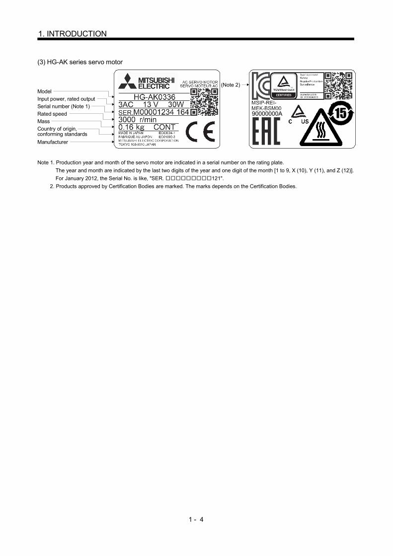
(3) HG-AK series servo motor
Model(Note 2)
Input power, rated output
Serial number (Note 1)
Rated speed
Mass
Country of origin,conforming standards
Manufacturer
90000000A
Note 1. Production year and month of the servo motor are indicated in a serial number on the rating plate.
The year and month are indicated by the last two digits of the year and one digit of the month [1 to 9, X (10), Y (11), and Z (12)].
For January 2012, the Serial No. is like, "SER. 121".
2. Products approved by Certification Bodies are marked. The marks depends on the Certification Bodies.
1 - 5
1. INTRODUCTION
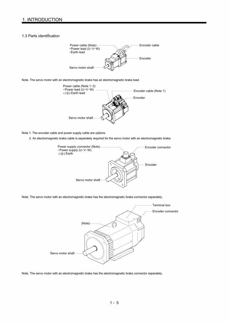
1.3 Parts identification
Power cable (Note) Power lead (U V W) Earth lead
Encoder cable
Encoder
Servo motor shaft
Note. The servo motor with an electromagnetic brake has an electromagnetic brake lead.
Encoder cable (Note 1)
Encoder
Servo motor shaft
Power cable (Note 1 2) Power lead (U V W) ( ) Earth lead
Note 1. The encoder cable and power supply cable are options.
2. An electromagnetic brake cable is separately required for the servo motor with an electromagnetic brake.
Power supply connector (Note) Power supply (U V W) ( ) Earth
Servo motor shaft
Encoder
Encoder connector
Note. The servo motor with an electromagnetic brake has the electromagnetic brake connector separately.
(Note)
Encoder connector
Terminal box
Servo motor shaft
Note. The servo motor with an electromagnetic brake has the electromagnetic brake connector separately.
1 - 6
1. INTRODUCTION
1.4 Electromagnetic brake
CAUTION
The electromagnetic brake is provided to prevent a drop at a power failure or alarm
occurrence during vertical drive or to hold a shaft at a stop. Do not use it for normal
braking (including braking at servo lock).
The electromagnetic brake has a time lag. Ensure enough time between releasing
the electromagnetic brake and starting the servo motor.
Be sure to check the time lag of the braking with an actual machine.
Configure an electromagnetic brake circuit so that it is activated also by an external
emergency stop switch.
For details of the circuit configuration and timing chart, refer to the Servo Amplifier
Instruction Manual.
While the electromagnetic brake is opened, the motor may be raised to high
temperature regardless of driving.
The life will be shorten under sudden acceleration/deceleration conditions.
The servo motor with an electromagnetic brake can be used to prevent a drop in vertical lift applications or to
ensure double safety at an emergency stop, for example. When performing servo motor operation, supply
power to the electromagnetic brake to release the brake. Switching power off makes the brake effective.
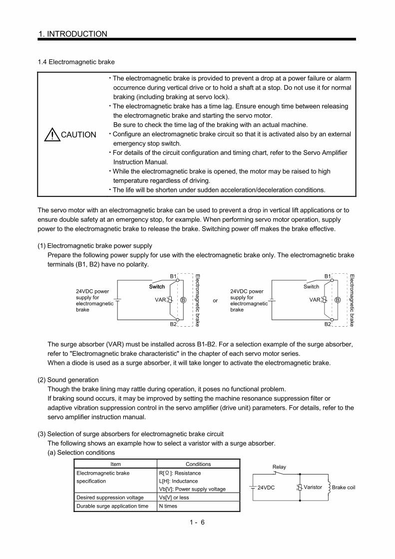
(1) Electromagnetic brake power supply
Prepare the following power supply for use with the electromagnetic brake only. The electromagnetic brake
terminals (B1, B2) have no polarity.
Switch
VAR
B1
U B
24VDC powersupply forelectromagnetic brake
B2
VAR
B1
U B
B2
or
Electrom
agnetic bra
ke
24VDC powersupply forelectromagnetic brake
Switch Switch
Electrom
agnetic bra
ke
The surge absorber (VAR) must be installed across B1-B2. For a selection example of the surge absorber,
refer to "Electromagnetic brake characteristic" in the chapter of each servo motor series.
When a diode is used as a surge absorber, it will take longer to activate the electromagnetic brake.
(2) Sound generation
Though the brake lining may rattle during operation, it poses no functional problem.
If braking sound occurs, it may be improved by setting the machine resonance suppression filter or
adaptive vibration suppression control in the servo amplifier (drive unit) parameters. For details, refer to the
servo amplifier instruction manual.
(3) Selection of surge absorbers for electromagnetic brake circuit
The following shows an example how to select a varistor with a surge absorber.
(a) Selection conditions Item Conditions
24VDC
Relay
Brake coilU Varistor
Electromagnetic brake
specification
R[ ]: Resistance
L[H]: Inductance
Vb[V]: Power supply voltage
Desired suppression voltage Vs[V] or less
Durable surge application time N times
1 - 7
1. INTRODUCTION
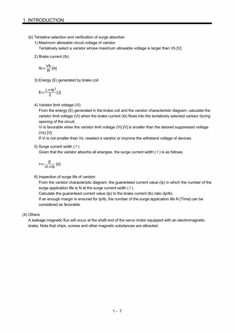
(b) Tentative selection and verification of surge absorber
1) Maximum allowable circuit voltage of varistor
Tentatively select a varistor whose maximum allowable voltage is larger than Vb [V].
2) Brake current (Ib)
Ib [A]VbR
3) Energy (E) generated by brake coil
E [J]L Ib
2
2
4) Varistor limit voltage (Vi) From the energy (E) generated in the brake coil and the varistor characteristic diagram, calculate the
varistor limit voltage (Vi) when the brake current (Ib) flows into the tentatively selected varistor during
opening of the circuit. Vi is favorable when the varistor limit voltage (Vi) [V] is smaller than the desired suppressed voltage
(Vs) [V].
If Vi is not smaller than Vs, reselect a varistor or improve the withstand voltage of devices.
5) Surge current width ( ) Given that the varistor absorbs all energies, the surge current width ( ) is as follows.
[s]EVi Ib
6) Inspection of surge life of varistor
From the varistor characteristic diagram, the guaranteed current value (Ip) in which the number of the
surge application life is N at the surge current width ( ). Calculate the guaranteed current value (lp) to the brake current (lb) ratio (lp/lb).
If an enough margin is ensured for Ip/Ib, the number of the surge application life N [Time] can be
considered as favorable.
(4) Others
A leakage magnetic flux will occur at the shaft end of the servo motor equipped with an electromagnetic
brake. Note that chips, screws and other magnetic substances are attracted.
1 - 8
1. INTRODUCTION
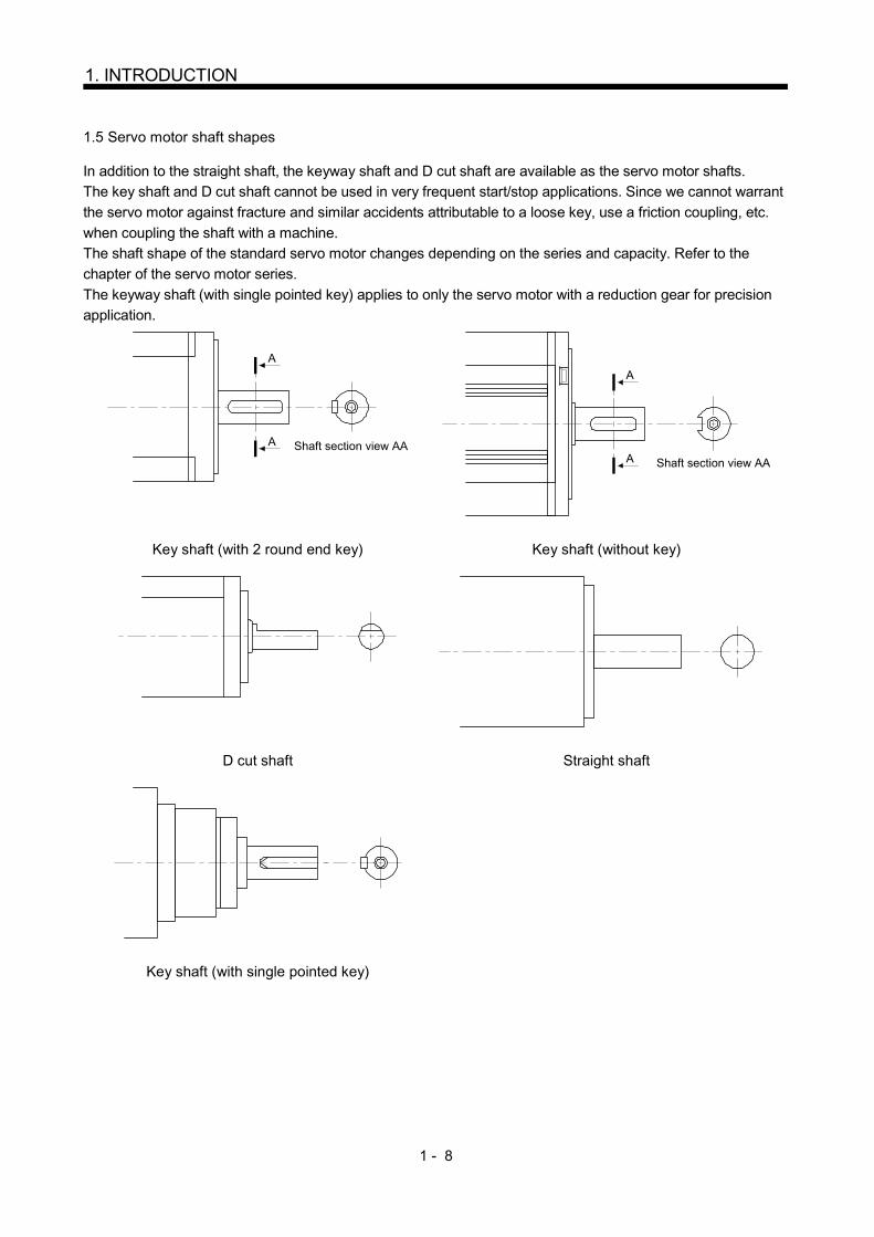
1.5 Servo motor shaft shapes
In addition to the straight shaft, the keyway shaft and D cut shaft are available as the servo motor shafts.
The key shaft and D cut shaft cannot be used in very frequent start/stop applications. Since we cannot warrant
the servo motor against fracture and similar accidents attributable to a loose key, use a friction coupling, etc.
when coupling the shaft with a machine.
The shaft shape of the standard servo motor changes depending on the series and capacity. Refer to the
chapter of the servo motor series.
The keyway shaft (with single pointed key) applies to only the servo motor with a reduction gear for precision
application.
Shaft section view AA
A
A
Shaft section view AA
A
A
Key shaft (with 2 round end key) Key shaft (without key)
D cut shaft Straight shaft
Key shaft (with single pointed key)

2 - 1
2. INSTALLATION
2. INSTALLATION
WARNING
To prevent electric shock, ground each equipment securely.
CAUTION
Stacking in excess of the limited number of products is not allowed. Install the servo motor on incombustible material. Installing them directly or close to combustibles will lead to smoke or a fire. Install the equipment in a load-bearing place in accordance with this Instruction Manual. Do not get on or put heavy load on the product to prevent injury. Use the equipment within the specified environmental condition range. Refer to the specifications of the servo motor series. Do not drop or strike the converter unit and servo amplifier (drive unit) and servo motor. Otherwise, injury, malfunction, etc. may occur. Do not install or operate a faulty servo motor. Do not hold the cables, connectors, shaft, or encoder when carrying the servo motor. Otherwise, it may drop. The lifting eyebolts of the servo motor may only be used to transport the servo motor. They must not be used to transport the servo motor when it is mounted on a machine. The servo motor with a reduction gear must be installed in the specified direction. Otherwise, it can leak oil, leading to a fire or fault. Securely fix the servo motor to the machine. If fixed insecurely, the servo motor will come off during operation, leading to injury. Be sure to measure the motor vibration level with the servo motor mounted to the machine when checking the vibration level. A great vibration may cause the early damage of a bearing, encoder, brake, and reduction gear. The great vibration may also cause the poor connector connection or bolt looseness. For the gain adjustment at the equipment startup, check the torque waveform and the speed waveform by using a measurement device, and then check that no vibration occurs. If the vibration occurs due to high gain, the vibration may cause the early damage of the servo motor. When coupling the shaft end of the servo motor, do not subject the shaft end to impact, such as hammering. The encoder may become faulty. When coupling a load to the servo motor, do not use a rigid coupling. Doing so can cause the shaft to break and the bearing to wear out. Balance the load to the extent possible. Failure to do so can cause vibration during servo motor operation or damage the bearings and encoder. Take safety measures, e.g. provide covers, to prevent accidental access to the rotating parts of the servo motor during operation. Do not subject the servo motor shaft to more than the permissible load. Otherwise, the shaft may break, leading to injury. When the product has been stored for an extended period of time, contact your local sales office. When handling the servo motor, be careful with the sharp edges of the servo motor, shaft keyway, or others. Do not use the servo motor where the shaft-through portion may be subject to pressure (e.g. compressed air). Applying air pressure to the inside of the servo motor may cause a malfunction.

2 - 2
2. INSTALLATION
2.1 Installation orientation
(1) Standard servo motor
The following table indicates the installation orientation of the standard servo motor.
Servo Motor Series Direction of Installation Remark
HF-MP HC-RP
HF-KP HC-UP
HF-SP HC-LP
HF-JP
May be installed in any
direction.
For installation in the horizontal direction, it is recommended to set the
connector section downward.
HA-LP(Flange Type)
HG-AK
HA-LP(Flange leg type)
For installation in the horizontal direction, make the legs face down and use
the legs or flange as an installation reference.
When using the flange as an installation reference, however, also fix the
legs supplementary.
For installation in the horizontal direction, it is recommended to set the connector section downward.
When mounting the servo motor vertically or obliquely, give a little slack for the connection cable.
Little slack
(2) Servo motor with an electromagnetic brake
The servo motor with an electromagnetic brake can also be installed in the same orientation as the
standard servo motor.
When the servo motor with an electromagnetic brake is installed with the shaft end at top, the brake plate
may generate sliding sound but it is not a fault.
(3) Servo motor with a reduction gear
The orientation of installing the servo motor with a reduction gear changes depending on the reduction gear
type. Be sure to install it in the specified orientation. Refer to the chapter of the servo motor series for
details. 2.2 Cooling fan
For the servo motor with a cooling fan, ensure to put enough space for the distance L between intake port and
wall surface.
L or longer
Servo motor
Cooling fan
Intake
2 - 3
2. INSTALLATION
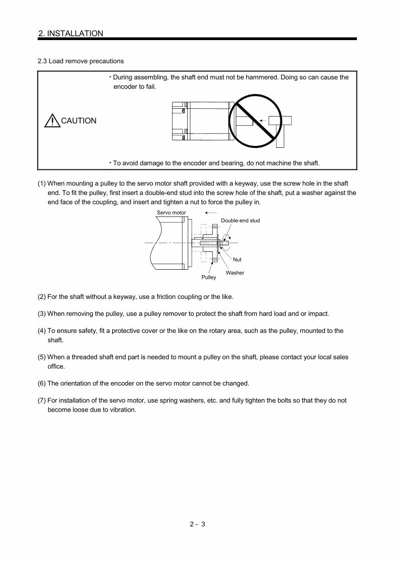
2.3 Load remove precautions
CAUTION
During assembling, the shaft end must not be hammered. Doing so can cause the
encoder to fail.
To avoid damage to the encoder and bearing, do not machine the shaft.
(1) When mounting a pulley to the servo motor shaft provided with a keyway, use the screw hole in the shaft
end. To fit the pulley, first insert a double-end stud into the screw hole of the shaft, put a washer against the
end face of the coupling, and insert and tighten a nut to force the pulley in.
Servo motor
Double-end stud
Nut
WasherPulley
(2) For the shaft without a keyway, use a friction coupling or the like.
(3) When removing the pulley, use a pulley remover to protect the shaft from hard load and or impact.
(4) To ensure safety, fit a protective cover or the like on the rotary area, such as the pulley, mounted to the
shaft.
(5) When a threaded shaft end part is needed to mount a pulley on the shaft, please contact your local sales
office.
(6) The orientation of the encoder on the servo motor cannot be changed.
(7) For installation of the servo motor, use spring washers, etc. and fully tighten the bolts so that they do not
become loose due to vibration.

2 - 4
2. INSTALLATION
2.4 Permissible load for the shaft
CAUTION Do not use a rigid coupling as it may apply excessive bending load to the shaft of
the servo motor, leading the shaft to break and the bearing to wear out.
For the permissible shaft load specific to the servo motor, refer to the chapter of the servo motor series.
(1) Use a flexible coupling and make sure that the misalignment of the shaft is less than the permissible radial
load.
(2) When using a pulley, sprocket or timing belt, select a diameter that will fit into the permissible radial load.
(3) Excess of the permissible load can cause the bearing life to reduce and the shaft to break.
(4) The load indicated in this section is static load in a single direction and does not include eccentric load.
Make eccentric load as small as possible. Not doing so can cause the servo motor to be damaged. 2.5 Protection from oil and water
Provide adequate protection to prevent foreign matter, such as oil from entering the servo motor shaft. When
installing the servo motor, consider the items in this section.
(1) Do not use the servo motor with its cable soaked in oil or water.
Cover
Capillary phenomenon
Oil/water pool
Servomotor
(2) When the servo motor is to be installed with the shaft end at top, provide measures so that it is not exposed
to oil and water entering from the machine side, gear box, etc.
Gear
Lubricating oil
Servo motor
(3) If the servo motor is exposed to oil such as coolant, the sealant, packing, cable and others may be affected
depending on the oil type.
(4) In the environment where the servo motor is exposed to oil mist, oil, water, grease and/or like, a standard
specifications servo motor may not be usable. Please contact your local sales office.

2 - 5
2. INSTALLATION
2.6 Cable
The power supply and encoder cables routed from the servo motor should be fixed to the servo motor to keep
them unmovable. Otherwise, cable breaks may occur. In addition, do not modify the connectors, terminals and
others at the ends of the cables. 2.7 Servo motor with oil seal
For the servo motor with oil seal, the oil seal prevents the entry of oil into the servo motor. Make sure to install
it according in this section. The functions have no problem even if the servo motor with oil seal may sound
during operation.
(1) Pressure and oil level
Install the servo motor horizontally, and set the oil level in the gear box to be lower than the oil seal lip
always. If the oil level is higher than the oil seal lip, the oil that entered into the servo motor may cause any
failure.
GearShaft
Servo motor
Oil seal
Height above oil level h
Lip
High pressure against the oil seal causes the abrasion and makes the life be short. Keep constant internal
pressure by equipping a ventilator to the gear box.
(2) Temperature
High temperature against the oil seal lip makes the life be short. Avoid exposing the oil seal lip to high
temperature oil since applicable temperature of the material is up to 100 (212 ) and temperature of the
oil seal lip rises within 10 to 15 (50 to 59 ) at maximum rotation. 2.8 Inspection
WARNING
Before starting maintenance and/or inspection, turn off the power and wait for 15
minutes or more (20 minutes or for drive unit 30kW or more) until the charge lamp turns off. Then, confirm that the voltage between P( ) and N( ) (L and L for
drive unit 30kW or more) is safe with a voltage tester and others. Otherwise, an
electric shock may occur. In addition, always confirm from the front of the servo
amplifier (converter unit), whether the charge lamp is off or not.
To avoid an electric shock, only qualified personnel should attempt inspections. For
repair and parts replacement, contact your safes representative.
CAUTION Do not perform insulation resistance test on the servo motor. Otherwise, it may
cause a malfunction.
Do not disassemble and/or repair the equipment on customer side.
It is recommended to make the following checks periodically.

2 - 6
2. INSTALLATION
(a) Check the servo motor bearings, brake section, etc. for unusual noise.
(b) Check the cables and the like for scratches and cracks. Especially when the junction cable is movable,
perform periodic inspection according to operating conditions.
(c) Check the servo motor shaft and coupling for misalignment.
(d) Check the power supply connector and encoder connector tightening screws for looseness. 2.9 Life
The following parts must be changed periodically as listed below. If any part is found faulty, it must be changed
immediately even when it has not yet reached the end of its life, which depends on the operating method and
environmental conditions. For parts replacement, please contact your local sales office.
Part name Guideline of life
Bearings 20,000 to 30,000 hours
Encoder 20,000 to 30,000 hours
Cooling fan 20,000 hours
Oil seal 5,000 hours
Reducer 10,000 to 20,000 hours
(a) Bearings
When the servo motor is run at rated speed under rated load, bearings change the bearings in 20,000 to
30,000 hours as a guideline. This differs on the operating conditions. The bearings must also be
changed if unusual noise or vibration is found during inspection.
(b) Oil seal (including oil seal used on the reduction gear)
Must be changed in 5,000 hours of operation at rated speed as a guideline. These parts must also be
changed if oil leakage, etc. is found during inspection.
The functions have no problem even if an oil seal may sound during operation. 2.10 Machine accuracies
The following table indicates the machine accuracies of the servo motor around the output shaft and mounting.
(except the optional products)
Accuracy [mm] Measuring
position
Flange size
Less than
100 130 176 to 250 280 to 350
Runout of flange surface to output shaft a) 0.05 0.06 0.08 0.08
Runout of fitting OD of flange surface b) 0.04 0.04 0.06 0.08
Runout of output shaft end c) 0.02 0.02 0.03 0.03
Reference diagram
c)
b)
a) A
A
A
2 - 7
2. INSTALLATION
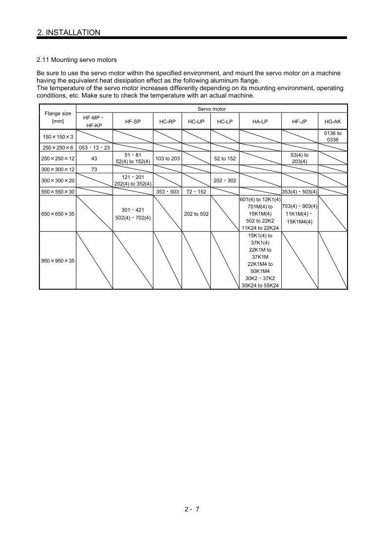
2.11 Mounting servo motors
Be sure to use the servo motor within the specified environment, and mount the servo motor on a machine having the equivalent heat dissipation effect as the following aluminum flange. The temperature of the servo motor increases differently depending on its mounting environment, operating conditions, etc. Make sure to check the temperature with an actual machine.
Flange size
[mm]
Servo motor
HF-MP
HF-KP HF-SP HC-RP HC-UP HC-LP HA-LP HF-JP HG-AK
150 150 3 0136 to 0336
250 250 6 053 13 23
250 250 12 43 51 81
52(4) to 152(4) 103 to 203 52 to 152 53(4) to 203(4)
300 300 12 73
300 300 20 121 201
202(4) to 352(4) 202 302
550 550 30 353 503 72 152 353(4) 503(4)
650 650 35 301 421
502(4) 702(4) 202 to 502
601(4) to 12K1(4) 701M(4) to 15K1M(4)
502 to 22K2 11K24 to 22K24
703(4) 903(4)
11K1M(4)
15K1M4(4)
950 950 35
15K1(4) to 37K1(4)
22K1M to 37K1M
22K1M4 to 50K1M4
30K2 37K2 30K24 to 55K24

2 - 8
2. INSTALLATION
MEMO

3 - 1
3. CONNECTORS USED FOR SERVO MOTOR WIRING
3. CONNECTORS USED FOR SERVO MOTOR WIRING
POINT
The IP rating indicated is the connector's protection against ingress of dust and
water when the connector is connected to a servo amplifier or servo motor. If the
IP rating of the connector, servo amplifier and servo motor vary, the overall IP
rating depends on the lowest IP rating of all components. 3.1 Selection of connectors
Use the connector configuration products given in the table as the connectors for connection with the servo
motor. Refer to section 3.2 for the compatible connector configuration products.
(1) HF-MP Series HF-KP Series
Encoder connector Brake connector Power supply connector
Servo motor Wiring connector
For encoder For power supply For brake
HF-MP Connector configuration A Connector configuration B Connector configuration C
HF-KP
(2) HF-SP Series
Encoderconnector
Brake connector Power supply connector
Servo motor Wiring connector
For encoder For power supply For brake
HF-SP51 81
Connector configuration D
Connector configuration F
HF-SP52 to 152 Connector configuration E
HF-SP524 to 1524
HF-SP121 to 301
Connector configuration G HF-SP202 to 502
HF-SP2024 to 5024
HF-SP421
Connector configuration H HF-SP702
HF-SP7024
3 - 2
3. CONNECTORS USED FOR SERVO MOTOR WIRING
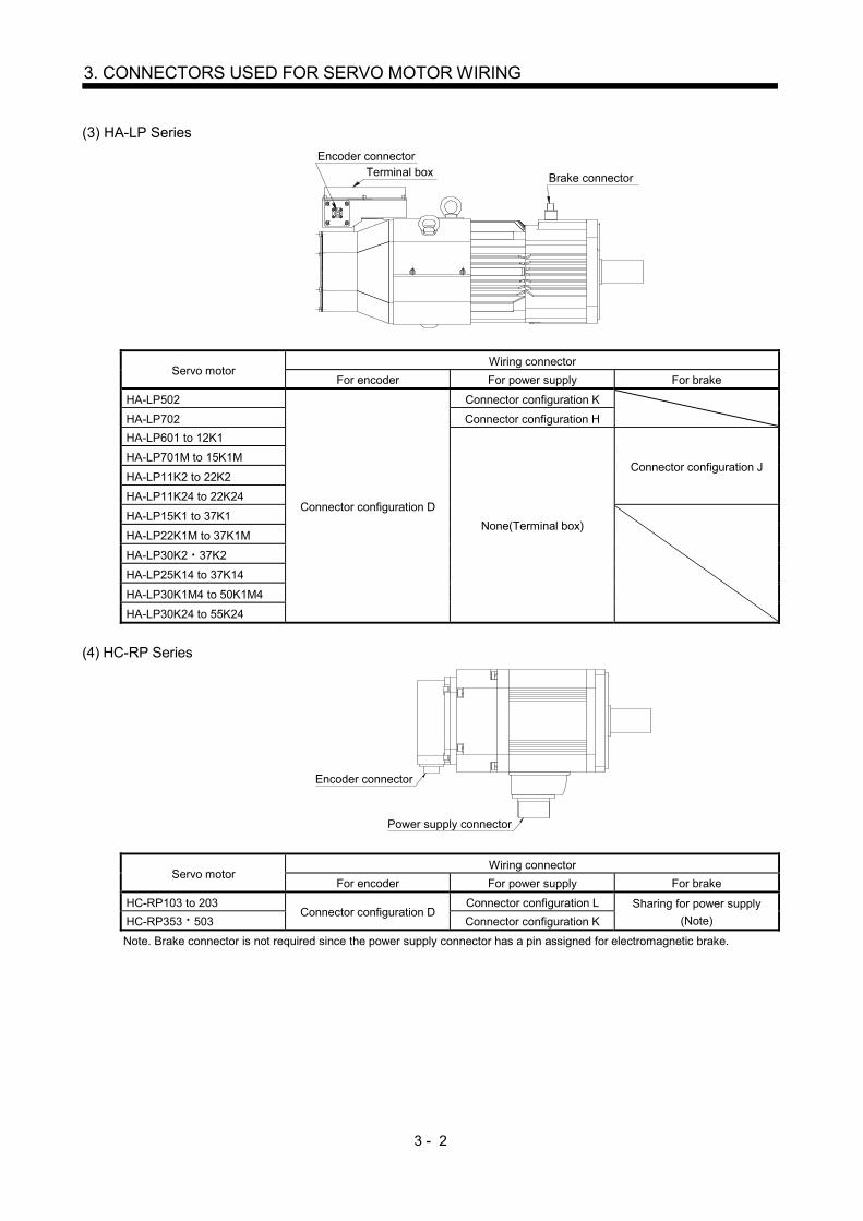
(3) HA-LP Series
Terminal boxEncoder connector
Brake connector
Servo motor Wiring connector
For encoder For power supply For brake
HA-LP502
Connector configuration D
Connector configuration K
HA-LP702 Connector configuration H
HA-LP601 to 12K1
None(Terminal box)
Connector configuration J HA-LP701M to 15K1M
HA-LP11K2 to 22K2
HA-LP11K24 to 22K24
HA-LP15K1 to 37K1
HA-LP22K1M to 37K1M
HA-LP30K2 37K2
HA-LP25K14 to 37K14
HA-LP30K1M4 to 50K1M4
HA-LP30K24 to 55K24
(4) HC-RP Series
Encoder connector
Power supply connector
Servo motor Wiring connector
For encoder For power supply For brake
HC-RP103 to 203 Connector configuration D
Connector configuration L Sharing for power supply
(Note) HC-RP353 503 Connector configuration K
Note. Brake connector is not required since the power supply connector has a pin assigned for electromagnetic brake.
3 - 3
3. CONNECTORS USED FOR SERVO MOTOR WIRING
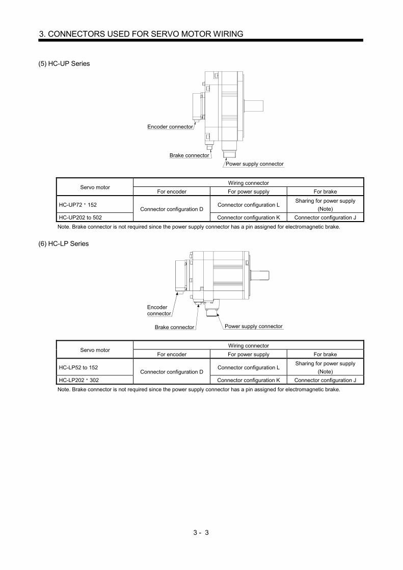
(5) HC-UP Series
Encoder connector
Power supply connector
Brake connector
Servo motor Wiring connector
For encoder For power supply For brake
HC-UP72 152 Connector configuration D
Connector configuration L Sharing for power supply
(Note)
HC-UP202 to 502 Connector configuration K Connector configuration J
Note. Brake connector is not required since the power supply connector has a pin assigned for electromagnetic brake.
(6) HC-LP Series
Encoder connector
Power supply connectorBrake connector
Servo motor Wiring connector
For encoder For power supply For brake
HC-LP52 to 152 Connector configuration D
Connector configuration L Sharing for power supply
(Note)
HC-LP202 302 Connector configuration K Connector configuration J
Note. Brake connector is not required since the power supply connector has a pin assigned for electromagnetic brake.

3 - 4
3. CONNECTORS USED FOR SERVO MOTOR WIRING
(7) HF-JP Series
Up
Encoderconnector
Power supply connectorBrake connector
Down
Servo motor Wiring connector
For encoder For power supply For brake
HF-JP53 to 203 Connector configuration E
HF-JP534 to 5034
HF-JP353 503 Connector configuration D Connector configuration G Connector configuration F
HF-JP703 903
Connector configuration H
HF-JP7034 9034
HF-JP11K1M 15K1M Connector configuration M, N Connector configuration J
HF-JP11K1M4 15K1M4
(8) HG-AK Series
Power supply connector
Encoder connector
Servo motor Wiring connector
For encoder For power supply For brake
HG-AK0136 to 0336 Connector configuration P Connector configuration Q Sharing for power supply

3 - 5
3. CONNECTORS USED FOR SERVO MOTOR WIRING
3.2 Wiring connectors (Connector configurations A B C)
Connector
configuration Feature Connector Crimping tool
Servo motor encoder
connector
A IP65 Connector: 2174053-1
(TE Connectivity)
For ground clip: 1596970-1
For REC. contact: 1596847-1
(TE Connectivity)
1674339-1
(TE Connectivity)
Connector
configuration Feature Connector Crimping tool
Servo motor power supply
connector
B IP65
Connector: KN4FT04SJ1-R
HOOD/SOCKET INSULATOR/
BUSHING/GROUND NUT
Contact: ST-TMH-S-C1B-100 (A534G)
(JAE)
CT170-14-TMH5B
(JAE)
JN4AT04NJ1
(JAE)
Connector
configuration Feature Connector Crimping tool
Servo motor
electromagnetic brake
connector
C IP65
Connector: JN4FT02SJ1-R
HOOD/SOCKET INSULATOR/
BUSHING/GROUND NUT
Contact: ST-TMH-S-C1B-100 (A534G)
(JAE)
CT170-14-TMH5B
(JAE)
JN4AT02PJ1
(JAE)
3 - 6
3. CONNECTORS USED FOR SERVO MOTOR WIRING
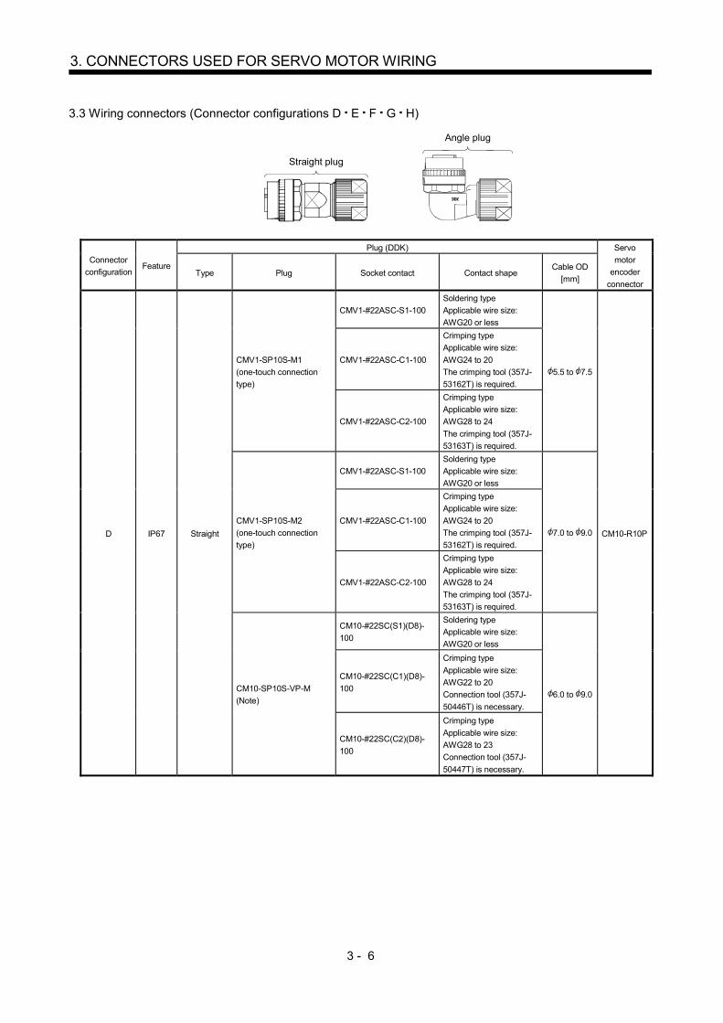
3.3 Wiring connectors (Connector configurations D E F G H)
Straight plug
Angle plug
Connector
configuration Feature
Plug (DDK) Servo
motor
encoder
connector Type Plug Socket contact Contact shape
Cable OD
[mm]
D IP67 Straight
CMV1-SP10S-M1
(one-touch connection
type)
CMV1-#22ASC-S1-100
Soldering type
Applicable wire size:
AWG20 or less
5.5 to 7.5
CM10-R10P
CMV1-#22ASC-C1-100
Crimping type
Applicable wire size:
AWG24 to 20
The crimping tool (357J-
53162T) is required.
CMV1-#22ASC-C2-100
Crimping type
Applicable wire size:
AWG28 to 24
The crimping tool (357J-
53163T) is required.
CMV1-SP10S-M2
(one-touch connection
type)
CMV1-#22ASC-S1-100
Soldering type
Applicable wire size:
AWG20 or less
7.0 to 9.0
CMV1-#22ASC-C1-100
Crimping type
Applicable wire size:
AWG24 to 20
The crimping tool (357J-
53162T) is required.
CMV1-#22ASC-C2-100
Crimping type
Applicable wire size:
AWG28 to 24
The crimping tool (357J-
53163T) is required.
CM10-SP10S-VP-M
(Note)
CM10-#22SC(S1)(D8)-
100
Soldering type
Applicable wire size:
AWG20 or less
6.0 to 9.0
CM10-#22SC(C1)(D8)-
100
Crimping type
Applicable wire size:
AWG22 to 20
Connection tool (357J-
50446T) is necessary.
CM10-#22SC(C2)(D8)-
100
Crimping type
Applicable wire size:
AWG28 to 23
Connection tool (357J-
50447T) is necessary.

3 - 7
3. CONNECTORS USED FOR SERVO MOTOR WIRING
Connector
configuration Feature
Plug (DDK) Servo
motor
encoder
connector
Type Plug Socket contact Contact shape Cable OD
[mm]
D IP67 Angle
CMV1-AP10S-M1
(one-touch connection
type)
CMV1-#22ASC-S1-100
Soldering type
Applicable wire size:
AWG20 or less
5.5 to 7.5
CM10-R10P
CMV1-#22ASC-C1-100
Crimping type
Applicable wire size:
AWG24 to 20
The crimping tool (357J-
53162T) is required.
CMV1-#22ASC-C2-100
Crimping type
Applicable wire size:
AWG28 to 24
The crimping tool (357J-
53163T) is required.
CMV1-AP10S-M2
(one-touch connection
type)
CMV1-#22ASC-S1-100
Soldering type
Applicable wire size:
AWG20 or less
7.0 to 9.0
CMV1-#22ASC-C1-100
Crimping type
Applicable wire size:
AWG24 to 20
The crimping tool (357J-
53162T) is required.
CMV1-#22ASC-C2-100
Crimping type
Applicable wire size:
AWG28 to 24
The crimping tool (357J-
53163T) is required.
CM10-AP10S-VP-M
(Note)
CM10-#22SC(S1)(D8)-
100
Soldering type
Applicable wire size:
AWG20 or less
6.0 to 9.0
CM10-#22SC(C1)(D8)-
100
Crimping type
Applicable wire size:
AWG22 to 20
Connection tool (357J-
50446T) is necessary.
CM10-#22SC(C2)(D8)-
100
Crimping type
Applicable wire size:
AWG28 to 23
Connection tool (357J-
50447T) is necessary.
Note. Use this connector if there is a potential risk that a high vibration may be applied to connectors. The connector on the servo
motor side can be disconnected up to 5 times. Use dedicated tool 357J-52780T (DDK) or a spanner with a jaw size of 21mm.

3 - 8
3. CONNECTORS USED FOR SERVO MOTOR WIRING
Plug Cable clamp Cable Plug Cable clamp Cable
Connector
configuration Feature
Plug (DDK) Cable clamp (DDK) Servo motor
power supply
connector Type Model name
Cable OD
[mm]
(Reference)
Model name
E
IP67
EN compliant
Straight CE05-6A18-10SD-D-BSS
Applicable wire size: AWG14 to 12
8.5 to 11 CE3057-10A-2-D
MS3102A18-10P
10.5 to 14.1 CE3057-10A-1-D
Angle CE05-8A18-10SD-D-BAS
Applicable wire size: AWG14 to 12
8.5 to 11 CE3057-10A-2-D
10.5 to 14.1 CE3057-10A-1-D
(Note)
General environment
Straight D/MS3106B18-10S
Applicable wire size: AWG14 to 12
14.3
(Bushing ID) D/MS3057-10A
Angle D/MS3108B18-10S
Applicable wire size: AWG14 to 12
14.3
(Bushing ID) D/MS3057-10A
Note. Not compliant with the EN.
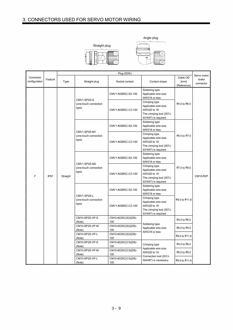
3 - 9
3. CONNECTORS USED FOR SERVO MOTOR WIRING
Straight plug
Angle plug
Connector
configuration Feature
Plug (DDK) Servo motor
brake
connector Type Straight plug Socket contact Contact shape
Cable OD
[mm]
(Reference)
F IP67 Straight
CMV1-SP2S-S
(one-touch connection
type)
CMV1-#22BSC-S2-100
Soldering type
Applicable wire size:
AWG16 or less
4.0 to 6.0
CM10-R2P
CMV1-#22BSC-C3-100
Crimping type
Applicable wire size:
AWG20 to 16
The crimping tool (357J-
53164T) is required.
CMV1-SP2S-M1
(one-touch connection
type)
CMV1-#22BSC-S2-100
Soldering type
Applicable wire size:
AWG16 or less
5.5 to 7.5
CMV1-#22BSC-C3-100
Crimping type
Applicable wire size:
AWG20 to 16
The crimping tool (357J-
53164T) is required.
CMV1-SP2S-M2
(one-touch connection
type)
CMV1-#22BSC-S2-100
Soldering type
Applicable wire size:
AWG16 or less
7.0 to 9.0
CMV1-#22BSC-C3-100
Crimping type
Applicable wire size:
AWG20 to 16
The crimping tool (357J-
53164T) is required.
CMV1-SP2S-L
(one-touch connection
type)
CMV1-#22BSC-S2-100
Soldering type
Applicable wire size:
AWG16 or less
9.0 to 11.6
CMV1-#22BSC-C3-100
Crimping type
Applicable wire size:
AWG20 to 16
The crimping tool (357J-
53164T) is required.
CM10-SP2S-VP-S
(Note)
CM10-#22SC(S2)(D8)-
100 Soldering type
Applicable wire size:
AWG16 or less
4.0 to 6.0
CM10-SP2S-VP-M
(Note)
CM10-#22SC(S2)(D8)-
100 6.0 to 9.0
CM10-SP2S-VP-L
(Note)
CM10-#22SC(S2)(D8)-
100 9.0 to 11.6
CM10-SP2S-VP-S
(Note)
CM10-#22SC(C3)(D8)-
100 Crimping type
Applicable wire size:
AWG20 to 16
Connection tool (357J-
50448T) is necessary.
4.0 to 6.0
CM10-SP2S-VP-M
(Note)
CM10-#22SC(C3)(D8)-
100 6.0 to 9.0
CM10-SP2S-VP-L
(Note)
CM10-#22SC(C3)(D8)-
100 9.0 to 11.6

3 - 10
3. CONNECTORS USED FOR SERVO MOTOR WIRING
Connector
configuration Feature
Plug (DDK) Servo motor
brake
connector Type Straight plug Socket contact Contact shape
Cable OD
[mm]
(Reference)
F IP67 Angle
CMV1-AP2S-S
(one-touch connection
type)
CMV1-#22BSC-S2-100
Soldering type
Applicable wire size:
AWG16 or less
4.0 to 6.0
CM10-R2P
CMV1-#22BSC-C3-100
Crimping type
Applicable wire size:
AWG20 to 16
The crimping tool (357J-
53164T) is required.
CMV1-AP2S-M1
(one-touch connection
type)
CMV1-#22BSC-S2-100
Soldering type
Applicable wire size:
AWG16 or less
5.5 to 7.5
CMV1-#22BSC-C3-100
Crimping type
Applicable wire size:
AWG20 to 16
The crimping tool (357J-
53164T) is required.
CMV1-AP2S-M2
(one-touch connection
type)
CMV1-#22BSC-S2-100
Soldering type
Applicable wire size:
AWG16 or less
7.0 to 9.0
CMV1-#22BSC-C3-100
Crimping type
Applicable wire size:
AWG20 to 16
The crimping tool (357J-
53164T) is required.
CMV1-AP2S-L
(one-touch connection
type)
CMV1-#22BSC-S2-100
Soldering type
Applicable wire size:
AWG16 or less
9.0 to 11.6
CMV1-#22BSC-C3-100
Crimping type
Applicable wire size:
AWG20 to 16
The crimping tool (357J-
53164T) is required.
CM10-AP2S-VP-S
(Note)
CM10-#22SC(S2)(D8)-
100 Soldering type
Applicable wire size:
AWG16 or less
4.0 to 6.0
CM10-AP2S-VP-M
(Note)
CM10-#22SC(S2)(D8)-
100 6.0 to 9.0
CM10-AP2S-VP-L
(Note)
CM10-#22SC(S2)(D8)-
100 9.0 to 11.6
CM10-AP2S-VP-S
(Note)
CM10-#22SC(C3)(D8)-
100 Crimping type
Applicable wire size:
AWG20 to 16
Connection tool (357J-
50448T) is necessary.
4.0 to 6.0
CM10-AP2S-VP-M
(Note)
CM10-#22SC(C3)(D8)-
100 6.0 to 9.0
CM10-AP2S-VP-L
(Note)
CM10-#22SC(C3)(D8)-
100 9.0 to 11.6
Note. Use this connector if there is a potential risk that a high vibration may be applied to connectors. The connector on the servo
motor side can be disconnected up to 5 times. Use dedicated tool 357J-52780T (DDK) or a spanner with a jaw size of 21mm.
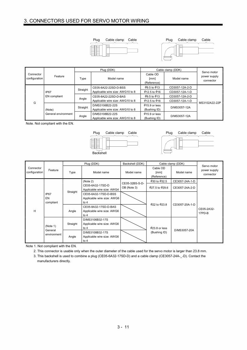
3 - 11
3. CONNECTORS USED FOR SERVO MOTOR WIRING
Plug Cable clamp Cable Plug Cable clamp Cable
Connector
configuration Feature
Plug (DDK) Cable clamp (DDK) Servo motor
power supply
connector Type Model name
Cable OD
[mm]
(Reference)
Model name
G
IP67
EN compliant
Straight CE05-6A22-22SD-D-BSS
Applicable wire size: AWG10 to 8
9.5 to 13 CD3057-12A-2-D
MS3102A22-22P
12.5 to 16 CD3057-12A-1-D
Angle CE05-8A22-22SD-D-BAS
Applicable wire size: AWG10 to 8
9.5 to 13 CD3057-12A-2-D
12.5 to 16 CD3057-12A-1-D
(Note)
General environment
Straight D/MS3106B22-22S
Applicable wire size: AWG10 to 8
15.9 or less
(Bushing ID) D/MS3057-12A
Angle D/MS3108B22-22S
Applicable wire size: AWG10 to 8
15.9 or less
(Bushing ID) D/MS3057-12A
Note. Not compliant with the EN.
Plug Cable clamp Cable Plug Cable clamp Cable
Backshell
Connector
configuration Feature
Plug (DDK) Backshell (DDK) Cable clamp (DDK) Servo motor
power supply
connector Type Model name Model name
Cable OD
[mm]
(Reference)
Model name
H
IP67
EN
compliant
Straight
(Note 2)
CE05-6A32-17SD-D
Applicable wire size: AWG4
CE05-32BS-S-D-
OB (Note 3)
30 to 32.5 CE3057-24A-1-D
CE05-2A32-
17PD-B
27.5 to 29.6 CE3057-24A-2-D
CE05-6A32-17SD-D-BSS
Applicable wire size: AWG6
to 4
22 to 23.8 CD3057-20A-1-D
Angle
CE05-8A32-17SD-D-BAS
Applicable wire size: AWG6
to 4
(Note 1)
General
environment
Straight
D/MS3106B32-17S
Applicable wire size: AWG6
to 4
23.8 or less
(Bushing ID) D/MS3057-20A
Angle
D/MS3108B32-17S
Applicable wire size: AWG6
to 4
Note 1. Not compliant with the EN.
2. This connector is usable only when the outer diameter of the cable used for the servo motor is larger than 23.8 mm.
3. This backshell is used to combine a plug (CE05-6A32-17SD-D) and a cable clamp (CE3057-24A-_-D). Contact the
manufacturers directly.
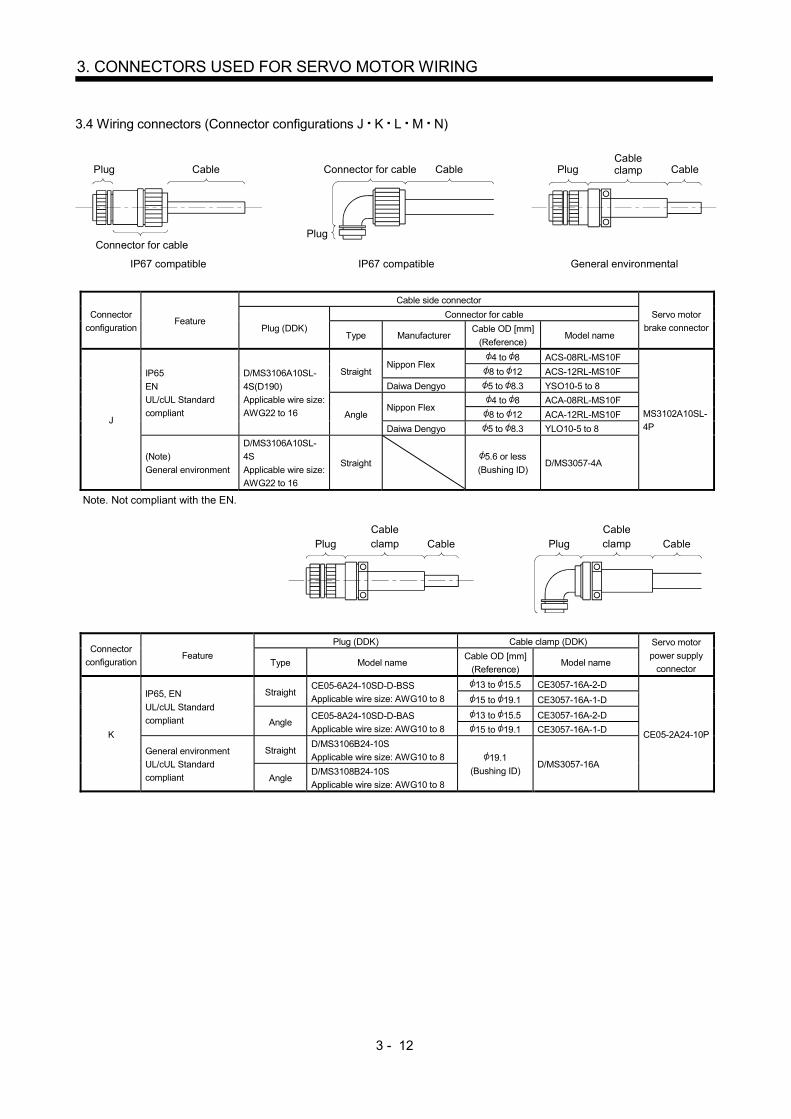
3 - 12
3. CONNECTORS USED FOR SERVO MOTOR WIRING
3.4 Wiring connectors (Connector configurations J K L M N)
IP67 compatible IP67 compatible General environmental
Plug Cable
Connector for cablePlug
Connector for cable Cable PlugCableclamp Cable
Connector
configuration Feature
Cable side connector
Servo motor
brake connector Plug (DDK)
Connector for cable
Type Manufacturer Cable OD [mm]
(Reference) Model name
J
IP65
EN
UL/cUL Standard
compliant
D/MS3106A10SL-
4S(D190)
Applicable wire size:
AWG22 to 16
Straight Nippon Flex
4 to 8 ACS-08RL-MS10F
MS3102A10SL-
4P
8 to 12 ACS-12RL-MS10F
Daiwa Dengyo 5 to 8.3 YSO10-5 to 8
Angle Nippon Flex
4 to 8 ACA-08RL-MS10F
8 to 12 ACA-12RL-MS10F
Daiwa Dengyo 5 to 8.3 YLO10-5 to 8
(Note)
General environment
D/MS3106A10SL-
4S
Applicable wire size:
AWG22 to 16
Straight 5.6 or less
(Bushing ID) D/MS3057-4A
Note. Not compliant with the EN.
PlugCable clamp Cable Plug
Cable clamp Cable
Connector
configuration Feature
Plug (DDK) Cable clamp (DDK) Servo motor
power supply
connector Type Model name
Cable OD [mm]
(Reference) Model name
K
IP65, EN
UL/cUL Standard
compliant
Straight CE05-6A24-10SD-D-BSS
Applicable wire size: AWG10 to 8
13 to 15.5 CE3057-16A-2-D
CE05-2A24-10P
15 to 19.1 CE3057-16A-1-D
Angle CE05-8A24-10SD-D-BAS
Applicable wire size: AWG10 to 8
13 to 15.5 CE3057-16A-2-D
15 to 19.1 CE3057-16A-1-D
General environment
UL/cUL Standard
compliant
Straight D/MS3106B24-10S
Applicable wire size: AWG10 to 8 19.1
(Bushing ID) D/MS3057-16A
Angle D/MS3108B24-10S
Applicable wire size: AWG10 to 8

3 - 13
3. CONNECTORS USED FOR SERVO MOTOR WIRING
PlugCable clamp Cable Plug
Cable clamp Cable
Connector
configuration Feature
Plug (DDK) Cable clamp (DDK) Servo motor
power supply
connector Type Model name
Cable OD [mm]
(Reference) Model name
L
IP65, EN
UL/cUL Standard
compliant
Straight CE05-6A22-23SD-D-BSS
Applicable wire size: AWG14 to 12
9.5 to 13 CE3057-12A-2-D
CE05-2A22-23P
12.5 to 16 CE3057-12A-1-D
Angle CE05-8A22-23SD-D-BAS
Applicable wire size: AWG14 to 12
9.5 to 13 CE3057-12A-2-D
12.5 to 16 CE3057-12A-1-D
General environment
UL/cUL Standard
compliant
Straight D/MS3106B22-23S
Applicable wire size: AWG14 to 12 15.9
(Bushing ID) D/MS3057-12A
Angle D/MS3108B22-23S
Applicable wire size: AWG14 to 12
PlugCableclamp Cable
Backshell
Backshell Cable
Cable clamp
Plug
Connector
configuration Feature
Plug (DDK) Backshell
(DDK)
Cable clamp (DDK) Servo motor
encoder
connector Type Model name Cable OD [mm] Model name
M IP67
EN compliant
Straight D/MS3106A20-29S
(D190)
CE02-20BS-D 6.8 to 10 CE3057-12A-3-D
D/MS3102A20-
29P Angle CE-20BA-S-D
PlugCableclamp Cable Plug
Cableclamp Cable
Connector
configuration Feature
Plug (DDK) Cable clamp (DDK) Servo motor
encoder
connector Type Model name Cable OD [mm] Model name
N (Note)
General environment
Straight D/MS3106B20-29S 15.9 or less
(Bushing ID) D/MS3057-12A
D/MS3102A20-
29P Angle D/MS3108B20-29S
Note. Not compliant with the EN.

3 - 14
3. CONNECTORS USED FOR SERVO MOTOR WIRING
3.5 Wiring connectors (Connector configurations P Q)
Connector
configuration
Connector (JST) Servo motor
encoder
connector Tab housing Tab contact Applicable wire size Insulator OD [mm] Crimping tool
P J21DPM-10V-KX SJ2M-01GF-M1.0N 0.20mm2 to 0.50mm2
(AWG24 to 20) 1.11 to 1.53 YRS-8861 J21DF-10V-KX-L
Connector
configuration
Connector (JST) Servo motor
encoder
connector Tab housing Tab contact Applicable wire size Insulator OD [mm] Crimping tool
Q J21DPM-06V-KX SJ2M-21GF-M1.0N 0.30mm2 to 0.75mm2 1.30 to 1.90 YRF-1120 J21DF-06V-KX-L

4 - 1
4. CONNECTOR DIMENSIONS
4. CONNECTOR DIMENSIONS
The connector dimensions for wiring the servo motor are shown below.
(1) TE Connectivity
2174053-1 [Unit: mm]
19.6
13.5
6.5
24.6
22
19
31.1
(Note)
13.6
Note. The recommended screw tightening torque is
0.1N m.
Crimping tool: 1596970-1 (for ground clip)
1596847-1 (for receptacle contact) (2) JAE
JN4FT02SJ1-R [Unit: mm]
26.617
12.3
19 14.3
11.8
2.5
(Note)
11.6
Note. The recommended screw tightening
torque is 0.2N m.
Crimping tool: CT170-14-TMH5B

4 - 2
4. CONNECTOR DIMENSIONS
KN4FT04SJ1-R
[Unit: mm]
16 0.3
11.7 0.2
Approx. 29
18.5
0
.3
24.5
0
.3
20.1
0
.2
7°
3.5
0.
2
12.2 0.3
13.7
0
.3
11
0.3
13
0.3
Main key
(Note)
R6
Note. The recommended screw tightening
torque is 0.2N m.
Crimping tool: CT170-14-TMH5B
(3) DDK
(a) CMV1-SP10S-M /CMV1-SP2S-
Refer to section 3.3 for details of crimping tools. [Unit: mm]
CMV1-SP2S-CMV1-SP10S-MApprox. 50
21 21
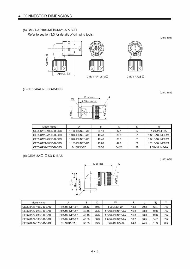
4 - 3
4. CONNECTOR DIMENSIONS
(b) CMV1-AP10S-M /CMV1-AP2S-
Refer to section 3.3 for details of crimping tools. [Unit: mm]
CMV1-AP10S-M CMV1-AP2S-21
Approx. 32
App
rox.
33
(c) CE05-6A - SD-D-BSS [Unit: mm]
WA
7.85 or more
C 0
.8
B0 0.3
8
D or less
Model name A B C D W
CE05-6A18-10SD-D-BSS 1 1/8-18UNEF-2B 34.13 32.1 57 1-20UNEF-2A
CE05-6A22-22SD-D-BSS 1 3/8-18UNEF-2B 40.48 38.3 61 1 3/16-18UNEF-2A
CE05-6A22-23SD-D-BSS 1 3/8-18UNEF-2B 40.48 38.3 61 1 3/16-18UNEF-2A
CE05-6A24-10SD-D-BSS 1 1/2-18UNEF-2B 43.63 42.0 68 1 7/16-18UNEF-2A
CE05-6A32-17SD-D-BSS 2-18UNS-2B 56.33 54.20 79 1 3/4-18UNS-2A
(d) CE05-8A - SD-D-BAS [Unit: mm]
W
AD or less
R 0
.7U
0.7
Y o
r m
ore
( S)
1 B0 0 .
38
Model name A B D W R U (S) Y
CE05-8A18-10SD-D-BAS 1 1/8-18UNEF-2B 34.13 69.5 1-20UNEF-2A 13.2 30.2 43.4 7.5
CE05-8A22-22SD-D-BAS 1 3/8-18UNEF-2B 40.48 75.5 1 3/16-18UNEF-2A 16.3 33.3 49.6 7.5
CE05-8A22-23SD-D-BAS 1 3/8-18UNEF-2B 40.48 75.5 1 3/16-18UNEF-2A 16.3 33.3 49.6 7.5
CE05-8A24-10SD-D-BAS 1 1/2-18UNEF-2B 43.63 86.3 1 7/16-18UNEF-2A 18.2 36.5 54.7 7.5
CE05-8A32-17SD-D-BAS 2-18UNS-2B 56.33 93.5 1 3/4-18UNS-2A 24.6 44.5 61.9 8.5
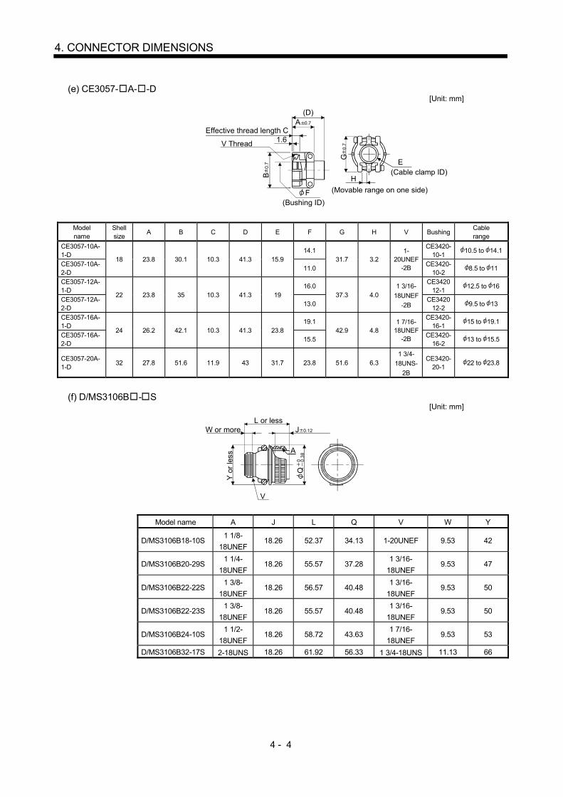
4 - 4
4. CONNECTOR DIMENSIONS
(e) CE3057- A- -D
[Unit: mm]
Effective thread length CA 0.7
1.6V Thread
B 0
.7 G
0.7
E(Cable clamp ID)
H
(Movable range on one side)
(D)
(Bushing ID)F
Model name
Shell size
A B C D E F G H V Bushing Cable range
CE3057-10A-1-D
18 23.8 30.1 10.3 41.3 15.9 14.1
31.7 3.2 1-
20UNEF-2B
CE3420-10-1
10.5 to 14.1
CE3057-10A-2-D
11.0 CE3420-
10-2 8.5 to 11
CE3057-12A-1-D
22 23.8 35 10.3 41.3 19 16.0
37.3 4.0 1 3/16-
18UNEF
-2B
CE342012-1
12.5 to 16
CE3057-12A-2-D
13.0 CE3420
12-2 9.5 to 13
CE3057-16A-1-D
24 26.2 42.1 10.3 41.3 23.8 19.1
42.9 4.8 1 7/16-
18UNEF-2B
CE3420-16-1
15 to 19.1
CE3057-16A-2-D
15.5 CE3420-
16-2 13 to 15.5
CE3057-20A-1-D
32 27.8 51.6 11.9 43 31.7 23.8 51.6 6.3 1 3/4-
18UNS-
2B
CE3420-20-1
22 to 23.8
(f) D/MS3106B - S [Unit: mm]
W or moreL or less
Y o
r le
ss
A
V
Q0.
380
J 0.12
Model name A J L Q V W Y
D/MS3106B18-10S 1 1/8-
18UNEF 18.26 52.37 34.13 1-20UNEF 9.53 42
D/MS3106B20-29S 1 1/4-
18UNEF 18.26 55.57 37.28
1 3/16-
18UNEF 9.53 47
D/MS3106B22-22S 1 3/8-
18UNEF 18.26 56.57 40.48
1 3/16-
18UNEF 9.53 50
D/MS3106B22-23S 1 3/8-
18UNEF 18.26 55.57 40.48
1 3/16-
18UNEF 9.53 50
D/MS3106B24-10S 1 1/2-
18UNEF 18.26 58.72 43.63
1 7/16-
18UNEF 9.53 53
D/MS3106B32-17S 2-18UNS 18.26 61.92 56.33 1 3/4-18UNS 11.13 66

4 - 5
4. CONNECTOR DIMENSIONS
(g) D/MS3108B - S
[Unit: mm]
W o
r m
ore
L or less J 0.12
A
V
U 0
.5R
0.5
Q0.
380
Model name A J L Q R U V W
D/MS3108B18-10S 1 1/8-18UNEF 18.26 68.27 34.13 20.5 30.2 1-20UNEF 9.53
D/MS3108B20-29S 1 1/4-18UNEF 18.26 76.98 37.28 22.5 33.3 1 3/16-
18UNEF 9.53
D/MS3108B22-22S 1 3/8-18UNEF 18.26 76.98 40.48 24.1 33.3 1 3/16-
18UNEF-2A 9.53
D/MS3108B22-23S 1 3/8-18UNEF 18.26 76.98 40.48 24.1 33.3 1 3/16-
18UNEF 9.53
D/MS3108B24-10S 1 1/2-18UNEF 18.26 86.51 43.63 25.6 36.5 1 7/16-
18UNEF 9.53
D/MS3108B32-17S 2-18UNS 18.26 95.25 56.33 32.8 44.4 1 3/4-18UNS 11.13
(h) D/MS3057- A [Unit: mm]
1.6
V
E (Bushing ID)
D (Cable clamp ID)
F (Movable range)
B 0
.7
A 0.7
G 0
.7
Effective thread length C
Model name Shell
size A B C D E F G V Bushing
D/MS3057-10A 18 23.8 30.1 10.3 15.9 14.3 3.2 31.7 1-20UNEF AN3420-10
D/MS3057-12A 22 23.8 35.0 10.3 19.0 15.9 4.0 37.3 1 3/16-
18UNEF-2A AN3420-12
D/MS3057-16A 24 28 26.2 42.1 10.3 23.8 19.1 4.8 42.9 1 7/16-18UNEF AN3420-16
D/MS3057-20A 32 27.8 51.6 11.9 31.7 23.8 6.3 51.6 1 3/4-18UNS AN3420-20
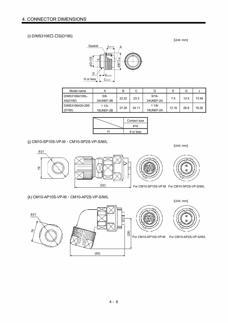
4 - 6
4. CONNECTOR DIMENSIONS
(i) D/MS3106 - S(D190)
[Unit: mm]
H or less
B 0
.38
0
G 0
.25
0.0
5
Gasket J 0.12
E 0.3
C 0.5
A
D
Model name A B C D E G J
D/MS3106A10SL-
4S(D190)
5/8-
24UNEF-2B 22.22 23.3
9/16-
24UNEF-2A 7.5 12.5 13.49
D/MS3106A20-29S
(D190)
1 1/4-
18UNEF-2B 37.28 34.11
1 1/8-
18UNEF-2A 12.16 26.8 18.26
Contact size
#16
H 8 or less
(j) CM10-SP10S-VP-M CM10-SP2S-VP-S/M/L [Unit: mm]
21
19
(52) For CM10-SP10S-VP-M For CM10-SP2S-VP-S/M/L
(k) CM10-AP10S-VP-M CM10-AP2S-VP-S/M/L [Unit: mm]
For CM10-AP10S-VP-M For CM10-AP2S-VP-S/M/L
(50)
(28)19
21
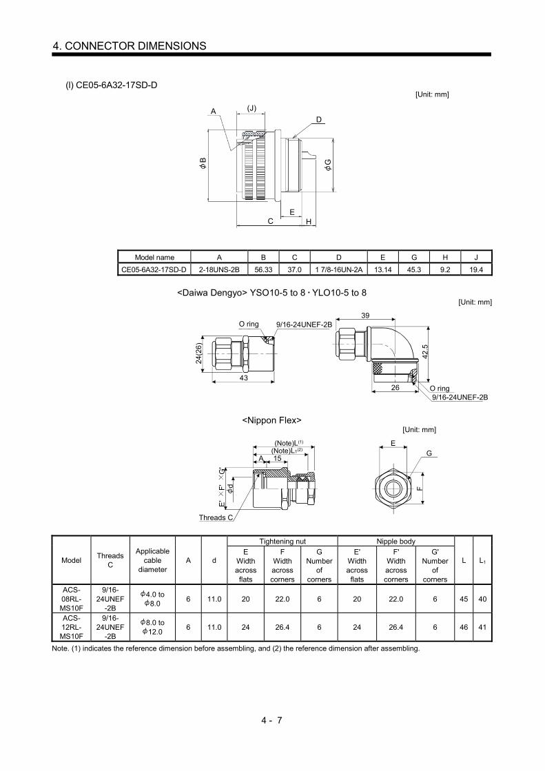
4 - 7
4. CONNECTOR DIMENSIONS
(l) CE05-6A32-17SD-D [Unit: mm]
D
B
A (J)
G
HE
C
Model name A B C D E G H J
CE05-6A32-17SD-D 2-18UNS-2B 56.33 37.0 1 7/8-16UN-2A 13.14 45.3 9.2 19.4
<Daiwa Dengyo> YSO10-5 to 8 YLO10-5 to 8 [Unit: mm]
O ring
O ring
4326
39
42.5
24(2
6 )
9/16-24UNEF-2B
9/16-24UNEF-2B
<Nippon Flex> [Unit: mm]
(Note)L(1)
(Note)L1(2)
A 15
Threads C
dE
'
F'
G
'
EG
F
Model Threads
C
Applicable cable
diameter A d
Tightening nut Nipple body
L L1 E
Width across flats
F Width across corners
G Number
of corners
E' Width across
flats
F' Width across corners
G' Number
of corners
ACS-08RL-MS10F
9/16-24UNEF
-2B
4.0 to 8.0
6 11.0 20 22.0 6 20 22.0 6 45 40
ACS-12RL-MS10F
9/16-24UNEF
-2B
8.0 to 12.0
6 11.0 24 26.4 6 24 26.4 6 46 41
Note. (1) indicates the reference dimension before assembling, and (2) the reference dimension after assembling.
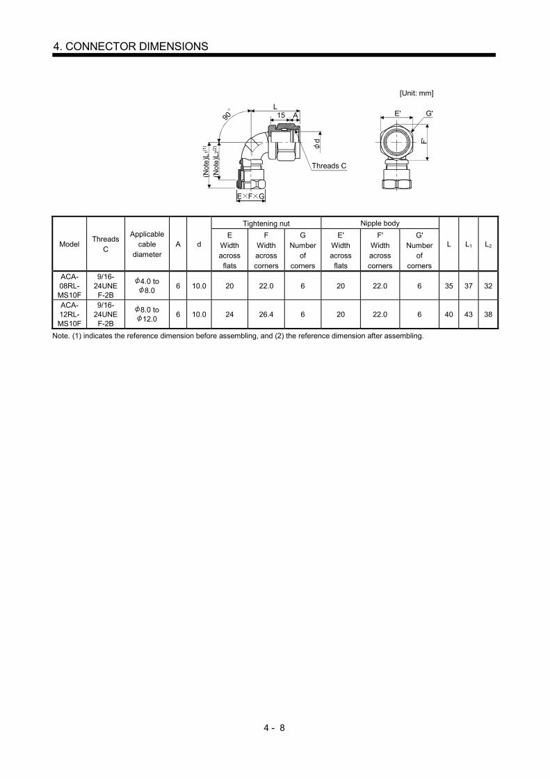
4 - 8
4. CONNECTOR DIMENSIONS
[Unit: mm]
Threads C
d
E F G
L
(No
te)L
1(1)
(No
te) L
2(2)
90 A15 E' G'
F'
Model Threads
C
Applicable cable
diameter A d
Tightening nut Nipple body
L L1 L2 E
Width across
flats
F Width across corners
G Number
of corners
E' Width across
flats
F' Width across corners
G' Number
of corners
ACA-08RL-MS10F
9/16-24UNEF-2B
4.0 to 8.0
6 10.0 20 22.0 6 20 22.0 6 35 37 32
ACA-12RL-MS10F
9/16-24UNEF-2B
8.0 to 12.0
6 10.0 24 26.4 6 20 22.0 6 40 43 38
Note. (1) indicates the reference dimension before assembling, and (2) the reference dimension after assembling.
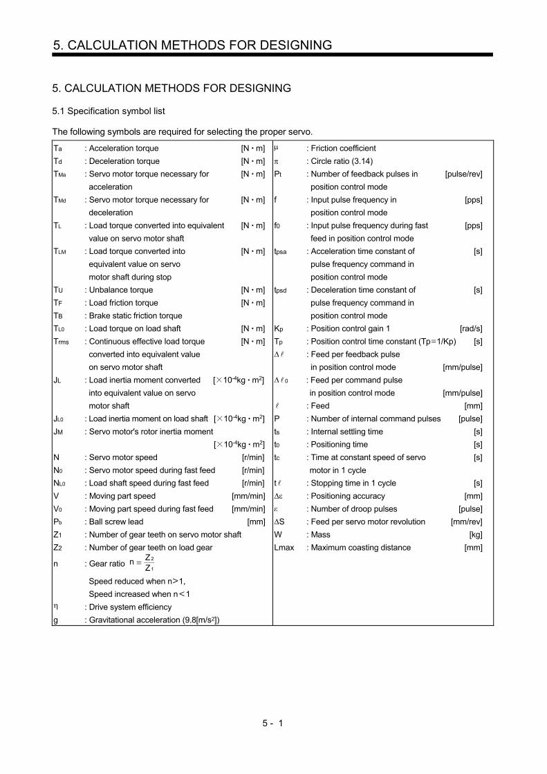
5 - 1
5. CALCULATION METHODS FOR DESIGNING
5. CALCULATION METHODS FOR DESIGNING
5.1 Specification symbol list
The following symbols are required for selecting the proper servo.
Ta : Acceleration torque [N m]
Td : Deceleration torque [N m]
TMa : Servo motor torque necessary for [N m]
acceleration
TMd : Servo motor torque necessary for [N m]
deceleration
TL : Load torque converted into equivalent [N m]
value on servo motor shaft
TLM : Load torque converted into [N m]
equivalent value on servo
motor shaft during stop
TU : Unbalance torque [N m]
TF : Load friction torque [N m]
TB : Brake static friction torque
TL0 : Load torque on load shaft [N m]
Trms : Continuous effective load torque [N m]
converted into equivalent value
on servo motor shaft
JL : Load inertia moment converted [ 10-4kg m2]
into equivalent value on servo
motor shaft
JL0 : Load inertia moment on load shaft [ 10-4kg m2]
JM : Servo motor's rotor inertia moment
[ 10-4kg m2]
N : Servo motor speed [r/min]
N0 : Servo motor speed during fast feed [r/min]
NL0 : Load shaft speed during fast feed [r/min]
V : Moving part speed [mm/min]
V0 : Moving part speed during fast feed [mm/min]
Pb : Ball screw lead [mm]
Z1 : Number of gear teeth on servo motor shaft
Z2 : Number of gear teeth on load gear
n : Gear ratio n
Z1
Z2
Speed reduced when n 1,
Speed increased when n 1
: Drive system efficiency
g : Gravitational acceleration (9.8[m/s2])
: Friction coefficient
: Circle ratio (3.14)
Pt : Number of feedback pulses in [pulse/rev]
position control mode
f : Input pulse frequency in [pps]
position control mode
f0 : Input pulse frequency during fast [pps]
feed in position control mode
tpsa : Acceleration time constant of [s]
pulse frequency command in
position control mode
tpsd : Deceleration time constant of [s]
pulse frequency command in
position control mode
Kp : Position control gain 1 [rad/s]
Tp : Position control time constant (Tp 1/Kp) [s]
: Feed per feedback pulse
in position control mode [mm/pulse]
0 : Feed per command pulse
in position control mode [mm/pulse]
: Feed [mm]
P : Number of internal command pulses [pulse]
ts : Internal settling time [s]
t0 : Positioning time [s]
tc : Time at constant speed of servo [s]
motor in 1 cycle
t : Stopping time in 1 cycle [s]
: Positioning accuracy [mm]
: Number of droop pulses [pulse]
S : Feed per servo motor revolution [mm/rev]
W : Mass [kg]
Lmax : Maximum coasting distance [mm]

5 - 2
5. CALCULATION METHODS FOR DESIGNING
5.2 Position resolution and electronic gear setting
Position resolution (travel distance per pulse ) is determined by travel distance per servo motor revolution S and the number of encoder feedback pulses Pt, and is represented by Equation 5.1. As the number of feedback pulses depends on the servo motor series, Refer to "Standard specifications list" in the chapter of each servo motor series.
Pt
S ................................................................................................................................................ (5.1)
: Travel distance per pulse [mm/pulse] S : Travel distance per servo motor revolution [mm/rev]
Pt : Number of feedback pulses [pulse/rev]
Since has the relationship represented by Equation 5.1, its value is fixed in the control system after the drive system and encoder have been determined. However, travel distance per command pulse can be set as desired using the parameters.
CMXCDV
M
Pt 262144pulse/rev
Command pulse frequency f0
Electronic gearCMXCDV
Deviationcounter
Encoder
Servo motor
As shown above, command pulses are multiplied by CMX/CDV set in the parameters to be position control pulses. Travel distance per command pulse is expressed by Equation 5.2.
0 Pt
SCMXCDV
CMXCDV .......................................................................................................... (5.2)
CMX : Electronic gear (Command pulse multiplication numerator) CDV : Electronic gear (Command pulse multiplication denominator)
Using the above relationship, travel distance per command pulse can be set to a value without fraction. [Setting example] Find a parameter value for 0 0.01 [mm] in a drive system where ball screw lead PB 10 [mm/pulse] and reduction ratio 1/n 1. The encoder feedback pulses Pt of the HF-KP 262144 [pulses/rev]. Since s 10 [mm/rev], the following is obtained according to Equation 5.2.
CMXCDV 0
Pt
S 0.01262144
10 32768125
<Relationship between position resolution and overall accuracy> Positioning accuracy of machine is the sum of electrical errors and mechanical errors. Normally, provisions should be made so that positioning accuracy are not affected by electrical system errors. As a guideline, Equation 5.3 should be satisfied.
15
110
to D ........................................................................................................................... (5.3)
where, : Travel distance per feedback pulse [mm/pulse]
: Positioning accuracy [mm]

5 - 3
5. CALCULATION METHODS FOR DESIGNING
5.3 Speed and command pulse frequency
The servo motor is run at a speed where the command pulses and feedback pulses are equivalent. Therefore, the command pulse frequency and feedback pulse frequency are equivalent. The relation including the parameter settings (CMX, CDV) is as indicated below (refer to the following diagram).
f0 CMXCDV Pt
N0
60 ....................................................................................................................... (5.4)
CMXCDV
f0
Electronicgear
Feedback pulsefrequency Servo motor
f0 : Command pulse frequency (Differential line driver) [pps]
CMX : Electronic gear (Commanded pulse multiplication numerator)
CDV : Electronic gear (Commanded pulse multiplication denominator)
N0 : Servo motor speed [r/min] Pt : Number of feedback pulses [pulses/rev]
(Pt 262144 for HF-KP) According to Equation 5.4, the following equations may be used to obtain the electronic gear and command pulse frequency to rotate the servo motor at N0.
Electronic gear
CMXCDV Pt
N0
601f0 ............................................................................................................................. (5.5)
Command pulse frequency
f0 Pt N0
60CDVCMX ............................................................................................................................. (5.6)
[Setting example] Obtain the command pulse frequency required to run the HF-KP at 3000r/min. When the electronic gear ratio 1 (initial parameter value) is used, the following result is found according to Equation 5.6.
f0 262144 N060
CDVCMX
(Command pulse frequency)
262144 300060 1
13107200[pps] However, as the maximum input command pulse frequency in the differential line driver type is 1Mpps, for general-purpose servo 13107200pps cannot be entered. To run the servo motor at the speed of 3000r/min at not more than 1Mpps, the electronic gear setting must be changed. This electronic gear is found by Equation 5.5.
CMXCDV
262144 300060
1
1 106
(Electronic gear)
8192625
Therefore, the parameters are set to CMX 8192 and CDV 625.

5 - 4
5. CALCULATION METHODS FOR DESIGNING
5.4 Stopping characteristics
(1) Droop pulses ( )
When a pulse train command is used to run the servo motor, there is a relationship between the command
pulse frequency and servo motor speed as shown in the figure. The difference between the command
pulses and feedback pulses during acceleration are called droop pulses, which are accumulated in the
servo amplifier (drive unit) deviation counter. Equation 5.7 defines a relationship between the command
pulse frequency (f) and position control gain 1(Kp).
f0
Kp[pulse] ......................................................................................................................................... (5.7)
Supposing that the value of position control gain 1 is 70 [rad/s], the droop pulses during operation will be as
follows at the command pulse frequency of 200 [kpps] according to Equation 5.7.
1200 103
2858[pulse]
Com
man
d pu
lse
freq
uen
cy f
Se
rvo
mot
or s
peed
[pps][r/min]0 Time
Command Droop pulses
Servo motorspeed
tpsa ts
ts 3 170
0.04
Tp
tpsd
(2) Settling time (ts) during linear acceleration/deceleration Since droop pulses still exist when there are no command pulses, settling time (ts) is required until the
servo motor stops. Set the operation pattern in consideration for the settling time.
The settling time (ts) value is obtained according to Equation 5.8.
ts 3 Tp
31
Kp[s] ............................................................................................................................................. (5.8)
*When Kp 70 [rad/s], ts 0.04 [s]. (Refer to the above diagram.)
The settling time (ts) indicates the time required for the servo motor to stop in the necessary positioning
accuracy range. This does not always mean that the servo motor has stopped completely. Thus, especially
when the servo motor is used in high-duty operation and positioning accuracy has no margin for travel distance per pulse ( ), the value obtained by Equation 5.8 must be increased.
The settling time (ts) will vary with the moving part conditions. Especially when the load friction torque is
large, movement may be unstable near the stopping position.

5 - 5
5. CALCULATION METHODS FOR DESIGNING
5.5 Capacity selection
As a first step, confirm the load conditions and temporarily select the servo motor capacity. Then, determine
the operation pattern, calculate required torques according to the following equations, and check that the servo
motor of the initially selected capacity may be used for operation . (1) Initial selection of servo motor capacity
After calculating the load torque (TL) and load inertia moment (JL), select a servo motor which will satisfy
the following two relationships.
Servo motor's rated torque TL
Servo motor JM JL/m
m 3 : High duty (more than 100 times/min.)
Settling time 40ms or less
m 5 : Middle duty (60 to 100 times/min.)
Settling time 100ms or less
m permissible load inertia moment : Low duty (less than 60 times/min.)
Settling time more than 100ms
Find the acceleration and deceleration torques and continuous effective load torque as described in (2) to
make a final selection. For high-duty positioning, the load inertia moment (JL) value should be as small as
possible. If positioning is infrequent as in line control, the load inertia moment (JL) value may be slightly
larger than in the above conditions. (2) Acceleration and deceleration torques
The following equations are used to calculate the acceleration and deceleration torques in the following operation pattern.
Com
man
d pu
lse
Se
rvo
mot
or s
peed
[r/m
in]
0
0
N0f0
Time
Time
Command
Servo motor speed
tpsa
Ta
TdDeceleration torque
Acceleration torque
freq
uen c
y f [
pps]
tpsd
Acceleration torque Ta (JL JM) N0
tpsa
19.55 104 ........................................................................................ (5.9)
Deceleration torque Tb (JL JM) N0
tpsd
19.55 104 ...................................................................................... (5.10)
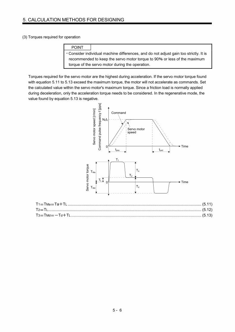
5 - 6
5. CALCULATION METHODS FOR DESIGNING
(3) Torques required for operation
POINT
Consider individual machine differences, and do not adjust gain too strictly. It is
recommended to keep the servo motor torque to 90 or less of the maximum
torque of the servo motor during the operation.
Torques required for the servo motor are the highest during acceleration. If the servo motor torque found
with equation 5.11 to 5.13 exceed the maximum torque, the motor will not accelerate as commands. Set
the calculated value within the servo motor's maximum torque. Since a friction load is normally applied
during deceleration, only the acceleration torque needs to be considered. In the regenerative mode, the
value found by equation 5.13 is negative.
tpsdtpsa
0
Servo motorspeed
Command
Time
Com
man
d pu
lse
freq
uenc
y f
[pps
]
Ser
vo m
otor
spe
ed [
r/m
in]
N0f0
0TL
TMd
TMa
Time
Ser
vo m
otor
tor
que
Ta
Td
T1
T2
T1 TMa Ta TL ................................................................................................................................ (5.11)
T2 TL ................................................................................................................................................... (5.12)
T3 TMd Td TL ............................................................................................................................. (5.13)
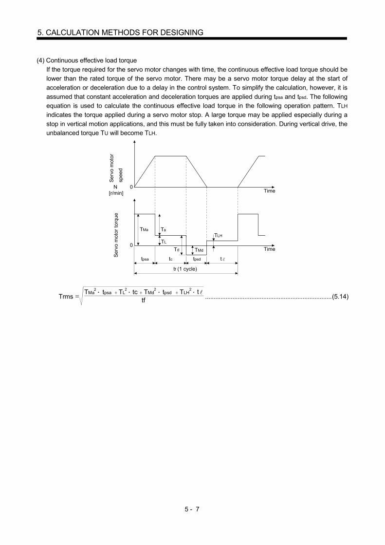
5 - 7
5. CALCULATION METHODS FOR DESIGNING
(4) Continuous effective load torque
If the torque required for the servo motor changes with time, the continuous effective load torque should be
lower than the rated torque of the servo motor. There may be a servo motor torque delay at the start of
acceleration or deceleration due to a delay in the control system. To simplify the calculation, however, it is
assumed that constant acceleration and deceleration torques are applied during tpsa and tpsd. The following
equation is used to calculate the continuous effective load torque in the following operation pattern. TLH
indicates the torque applied during a servo motor stop. A large torque may be applied especially during a
stop in vertical motion applications, and this must be fully taken into consideration. During vertical drive, the
unbalanced torque TU will become TLH.
Se
rvo
mot
or
spee
dS
ervo
mot
or t
orqu
e
N[r/min]
0Time
0Time
tpsa tc
tf (1 cycle)
TMa
TMdTd
Ta
TL
TLH
ttpsd
Trms tf
TMa tpsa TL tc TMd TLH t2 2 2 2tpsd .......................................................................... (5.14)

5 - 8
5. CALCULATION METHODS FOR DESIGNING
5.6 Load torque equations
Typical load torque equations are indicated below.
Type Mechanism Equation
Linear
movement
Servo motor
W
Z1
FCFG
Z2
TL F
N
V F S2 10 3 10 32 .................................... (5.15)
F : Force in the axial direction of the machine in linear motion [N]
F in Equation 5.15 is obtained with Equation 5.16 when the table is
moved, for example, as shown in the left diagram.
F Fc (W g FG) ....................................................... (5.16)
Fc : Force applied in the axial direction of the moving part [N]
FG : Tightening force of the table guide surface [N]
W : Full mass of the moving part [kg]
Rotary
movement
Servo motor
Z1 Z2
TL0
TL n1 1
TL0 TF ........................................................... (5.17)
TF : Load friction torque converted into equivalent value on servo
motor shaft [N m]
Vertical
movement
Counter weight
Servo motor
W2
W1
1/n
LoadGuide
During rise
TL TU TF ......................................................................... (5.18)
During fall
TL TU2
TF ................................................................ (5.19)
TF: Friction torque of the moving part [N m]
TU = 2 10 3
(W1 W2 )NV
2 103
g S(W1 W2 ) g .......................... (5.20)
TF = 1032g(W1 W2 ) S
........................................................ (5.21)
W1: Mass of load [kg]
W2: Mass of counterweight [kg]

5 - 9
5. CALCULATION METHODS FOR DESIGNING
5.7 Load inertia moment equations
Typical load inertia moment equations are indicated below.
Type Mechanism Equation
Cylinder
Axis of rotation is on the cylinder center
Axis of rotation
L
D1
D2
JL0 = 32L (D D )
4
1
4
2 8W (D D )
2
1
2
2 .......................... (5.22)
: Cylinder material density [kg/cm3]
L : Cylinder length [cm]
D1 : Cylinder outside diameter [cm]
D2 : Cylinder inside diameter [cm]
W : Cylinder mass [kg]
Reference data: material density
Iron : 7.8 10-3 [kg/cm3]
Aluminum : 2.7 10-3 [kg/cm3]
Copper : 8.96 10-3 [kg/cm3]
Axis of rotation is off the cylinder
Axis of rotation D
Rcenter
JL0 8W
(D 8R )2 2 .............................................................. (5.23)
Square block
Axis of rotation
R
aa b
b
JL0 W 3a2 b2
R2 ......................................................... (5.24)
W : Square block mass [kg]
a, b, R : Left diagram [cm]
Object which
moves linearly
Servo motor V
WN
JL W 600V
21W
N 10V
2
W20
2S
............. (5.25)
V : Speed of object moving linearly [mm/min]
S : Moving distance of object moving linearly per servo
motor revolution [mm/rev]
W : Object mass [kg]
Object that is
hung with pulley Servo motor
W
D
JL W 2D
2
Jp .................................................................. (5.26)
JP : Pulley inertia moment [ 10-4kg m2]
D : Pulley diameter [cm]
W : Object mass [kg]
Converted load
Load A JA
J31N3
J21
J11
J22 N2
N1
Load B JB
JL J11 (J21 J22 JA) N1
N22
(J31 JB)N1
N32
.................. (5.27)
JA, JB : Inertia moments of loads A, B [ 10-4kg m2]
J11 to J31 : Inertia moments [ 10-4kg m2]
N1 to N3 : Speed of each shaft [r/min]
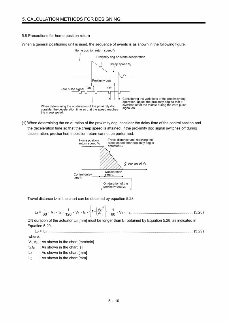
5 - 10
5. CALCULATION METHODS FOR DESIGNING
5.8 Precautions for home position return
When a general positioning unit is used, the sequence of events is as shown in the following figure.
Proximity dog on starts deceleration
Creep speed V2
Home position return speed V1
Proximity dog
On OffZero pulse signal
When determining the on duration of the proximity dog,consider the deceleration time so that the speed reachesthe creep speed.
Considering the variations of the proximity dogoperation, adjust the proximity dog so that itswitches off at the middle during the zero pulsesignal on.
(1) When determining the on duration of the proximity dog, consider the delay time of the control section and
the deceleration time so that the creep speed is attained. If the proximity dog signal switches off during
deceleration, precise home position return cannot be performed.
Home positionreturn speed V1
Control delaytime t1
Decelerationtime td
On duration of theproximity dog LD
Creep speed V2
Travel distance until reaching thecreep speed after proximity dog isdetected L1
Travel distance L1 in the chart can be obtained by equation 5.28.
L1 160 V1 t1
1120 V1 td 1
V1
V22
160 V1 Tp .............................................................. (5.28)
ON duration of the actuator LD [mm] must be longer than L1 obtained by Equation 5.28, as indicated in
Equation 5.29. LD L1 ................................................................................................................................................ (5.29)
where,
V1, V2 : As shown in the chart [mm/min] t1, td : As shown in the chart [s]
L1 : As shown in the chart [mm]
LD : As shown in the chart [mm]

5 - 11
5. CALCULATION METHODS FOR DESIGNING
(2) Set the end (OFF position) of the actuator signal at the middle of two ON positions (Lows) of the zero pulse
signal. If it is set near either ON position of the zero pulse signal, the positioning unit is liable to misdetect
the zero pulse signal. In this case, a fault will occur, e.g. the home position will shift by one revolution of the
servo motor.
The zero pulse output position can be confirmed by OP (encoder Z-phase pulse) on the external I/O signal
display. 5.9 Selection example
Machine specifications
Servomotor
Gear ratio 5:8
Servoamplifier
(drive unit)
Speed of moving part during fast feed V0 30000[mm/min]
Feed per command pulse 10[ m]
Travel 400[mm]
Positioning time t0 within 1[s]
Number of feeds 40[times/min]
Operation cycle tf 1.5[s]
Gear ratio n 8/5
Moving part mass W 60[kg]
Drive system efficiency 0.8
Friction coefficient 0.2
Ball screw lead Pb 16[mm]
Ball screw diameter 20[mm]
Ball screw length 500[mm]
Gear diameter (servo motor) 25[mm]
Gear diameter (load shaft) 40[mm]
Gear face width 10[mm]
(1) Selection of control parameters
Setting of electronic gear (command pulse multiplication numerator, denominator)
There is the following relationship between the multiplication setting and travel per pulse .
(ball screw lead)
262144 (gear ration) CDVCMX
When the above machining specifications are substituted in the above equation.
1610-310
262144 8/5CMXCDV
16262144 8/5CMX
CDV10
10002621441000
32768125
Acceptable as CMX/CDV is within 1/10 to 2000.
(2) Servo motor speed
N0 Pb
V0 n16
3000058
3000[r/min]
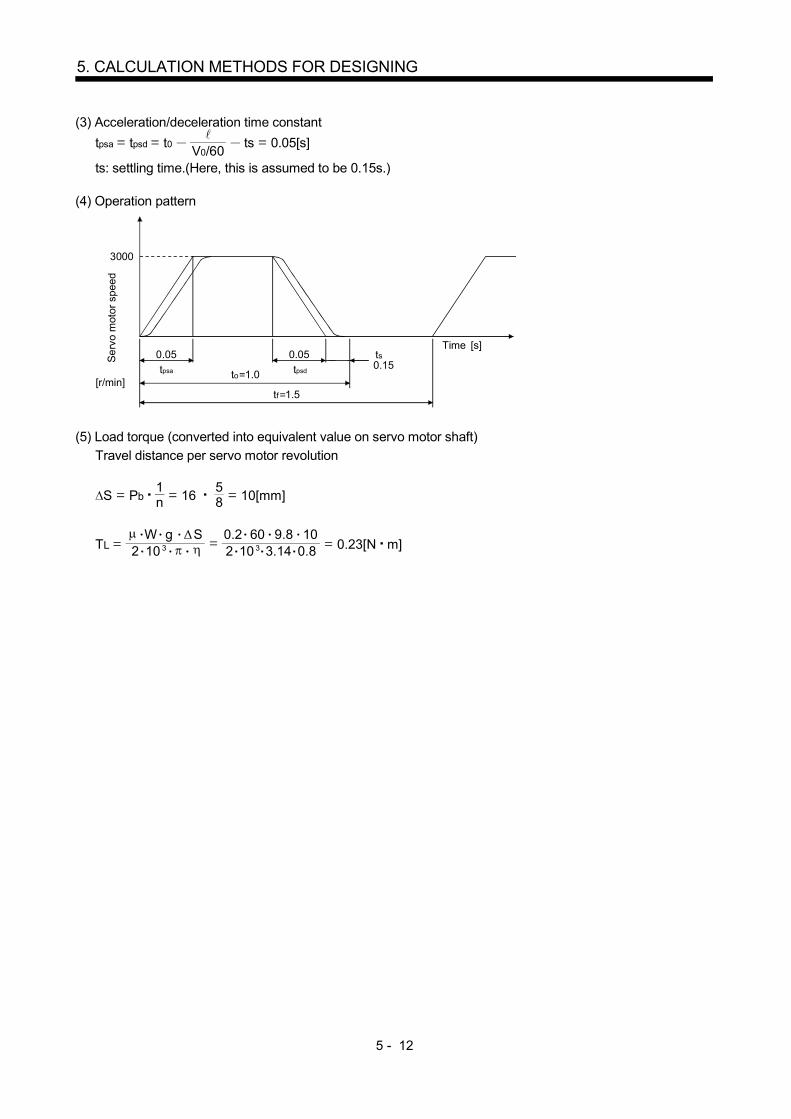
5 - 12
5. CALCULATION METHODS FOR DESIGNING
(3) Acceleration/deceleration time constant
tpsa tpsd t0 V0/60 ts 0.05[s]
ts: settling time.(Here, this is assumed to be 0.15s.) (4) Operation pattern
Se
rvo
mot
or s
peed
[r/min]
3000
Time 0.05
to 1.0
tf 1.5
0.05 tstpsa
0.15
[s]
tpsd
(5) Load torque (converted into equivalent value on servo motor shaft)
Travel distance per servo motor revolution
S Pb1n 16
58 10[mm]
TL 2 10 3
W g S10 3 3.14
0.2 60 9.8 100.82 0.23[N m]

5 - 13
5. CALCULATION METHODS FOR DESIGNING
(6) Load inertia moment (converted into equivalent value on servo motor shaft)
Moving part
JL1 W 20
2S 1.52[ 10-4kg m2]
Ball screw
JL2 32L
D4n
21 0.24[ 10-4kg m2]
* 7.8 10-3 [kg cm3]
Gear (servo motor shaft)
JL3 32L
D4 0.03[ 10-4kg m2]
Gear (load shaft)
JL4 32L
D4n
21 0.08[ 10-4kg m2]
Full load inertia moment (converted into equivalent value on servo motor shaft)
JL JL1 JL2 JL3 JL4 1.87[ 10-4kg m2] (7) Temporary selection of servo motor
Selection conditions
(a) Load torque servo motor's rated torque
(b) Full load inertia moment 24 servo motor inertia moment
From the above, the HF-KP23 (200W) is temporarily selected. (8) Acceleration and deceleration torques
Torque required for servo motor during acceleration
TMa (JL/ JM) N0
9.55 104 Tpsa TL 1.85[N m]
Torque required for servo motor during deceleration
TMd (JL JM) N0
9.55 104 Tpsd TL 0.86[N m]
The torque required for the servo motor during deceleration must be lower than the servo motor's maximum
torque.
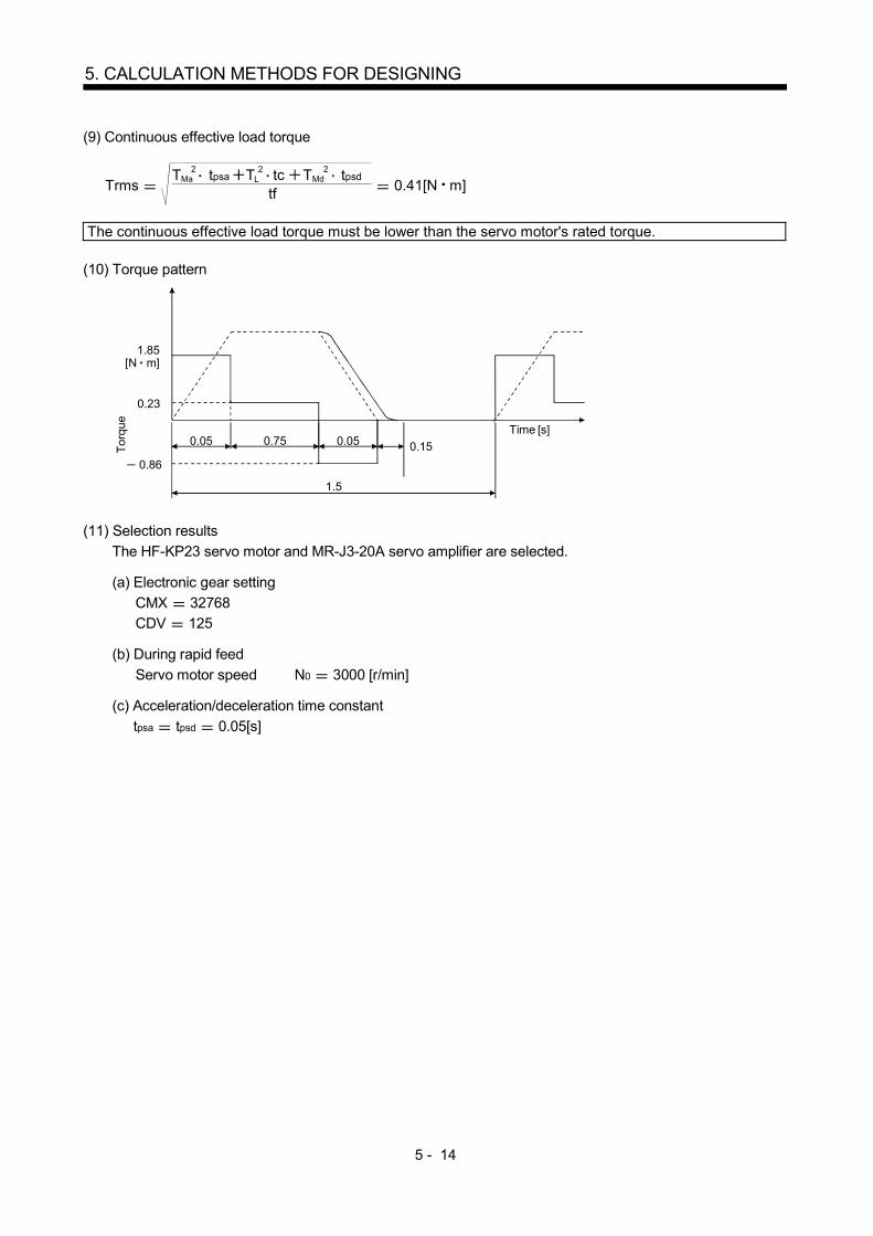
5 - 14
5. CALCULATION METHODS FOR DESIGNING
(9) Continuous effective load torque
Trms tf
T tpsa T tc T2 2 2Ma L Md tpsd
0.41[N m]
The continuous effective load torque must be lower than the servo motor's rated torque.
(10) Torque pattern
Tor
que
[N m]
0.23
Time [s]0.05 0.75 0.05
1.5
0.15
1.85
0.86
(11) Selection results
The HF-KP23 servo motor and MR-J3-20A servo amplifier are selected.
(a) Electronic gear setting
CMX 32768 CDV 125
(b) During rapid feed
Servo motor speed N0 3000 [r/min]
(c) Acceleration/deceleration time constant
tpsa tpsd 0.05[s]
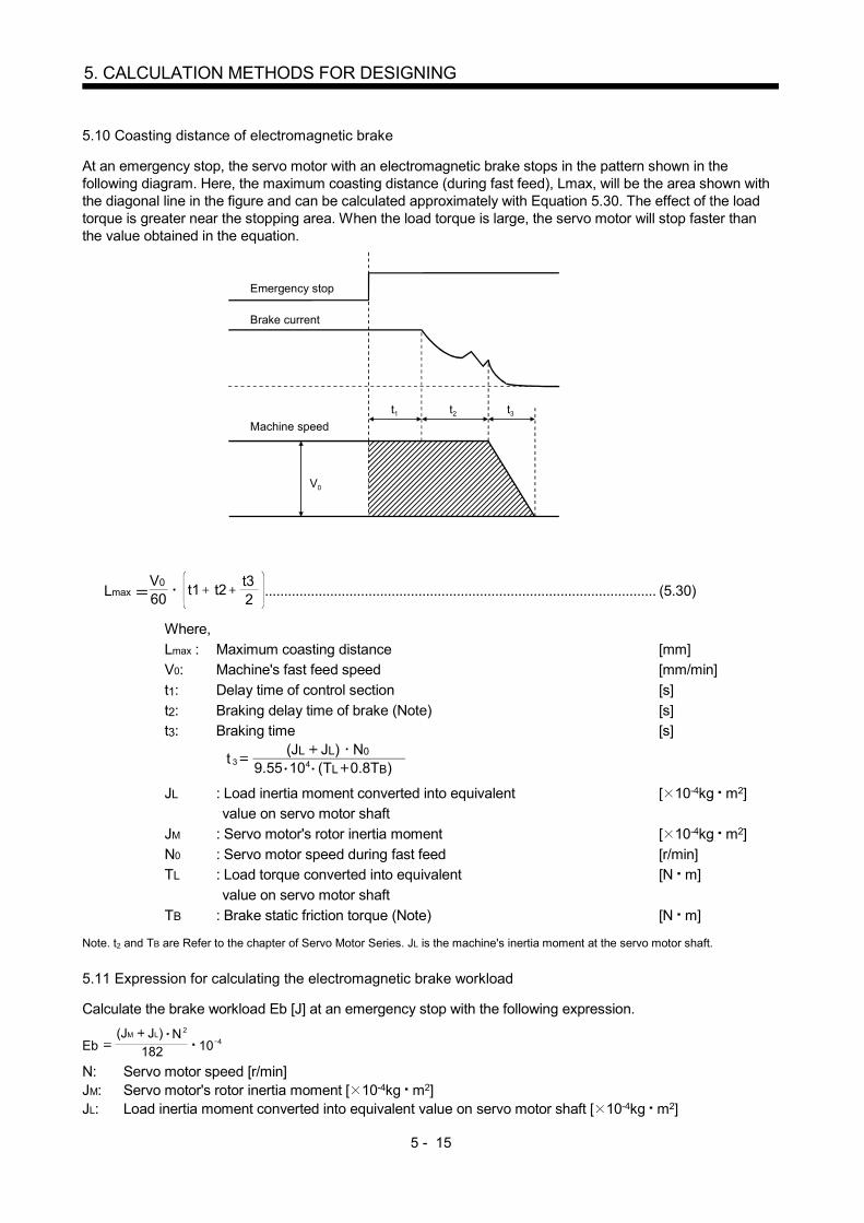
5 - 15
5. CALCULATION METHODS FOR DESIGNING
5.10 Coasting distance of electromagnetic brake
At an emergency stop, the servo motor with an electromagnetic brake stops in the pattern shown in the following diagram. Here, the maximum coasting distance (during fast feed), Lmax, will be the area shown with the diagonal line in the figure and can be calculated approximately with Equation 5.30. The effect of the load torque is greater near the stopping area. When the load torque is large, the servo motor will stop faster than the value obtained in the equation.
Emergency stop
Brake current
Machine speed
V0
t1 t2 t3
Lmax 60V0
t1 t22t3
...................................................................................................... (5.30)
Where,
Lmax : Maximum coasting distance [mm] V0: Machine's fast feed speed [mm/min]
t1: Delay time of control section [s]
t2: Braking delay time of brake (Note) [s] t3: Braking time [s]
9.55 104 (TL 0.8TB)(JL JL) N0
t 3
JL : Load inertia moment converted into equivalent [ 10-4kg m2] value on servo motor shaft
JM : Servo motor's rotor inertia moment [ 10-4kg m2]
N0 : Servo motor speed during fast feed [r/min] TL : Load torque converted into equivalent [N m]
value on servo motor shaft
TB : Brake static friction torque (Note) [N m] Note. t2 and TB are Refer to the chapter of Servo Motor Series. JL is the machine's inertia moment at the servo motor shaft.
5.11 Expression for calculating the electromagnetic brake workload
Calculate the brake workload Eb [J] at an emergency stop with the following expression.
182
(JM JL) N2
Eb 10 4
N: Servo motor speed [r/min] JM: Servo motor's rotor inertia moment [ 10-4kg m2] JL: Load inertia moment converted into equivalent value on servo motor shaft [ 10-4kg m2]

5 - 16
5. CALCULATION METHODS FOR DESIGNING
MEMO
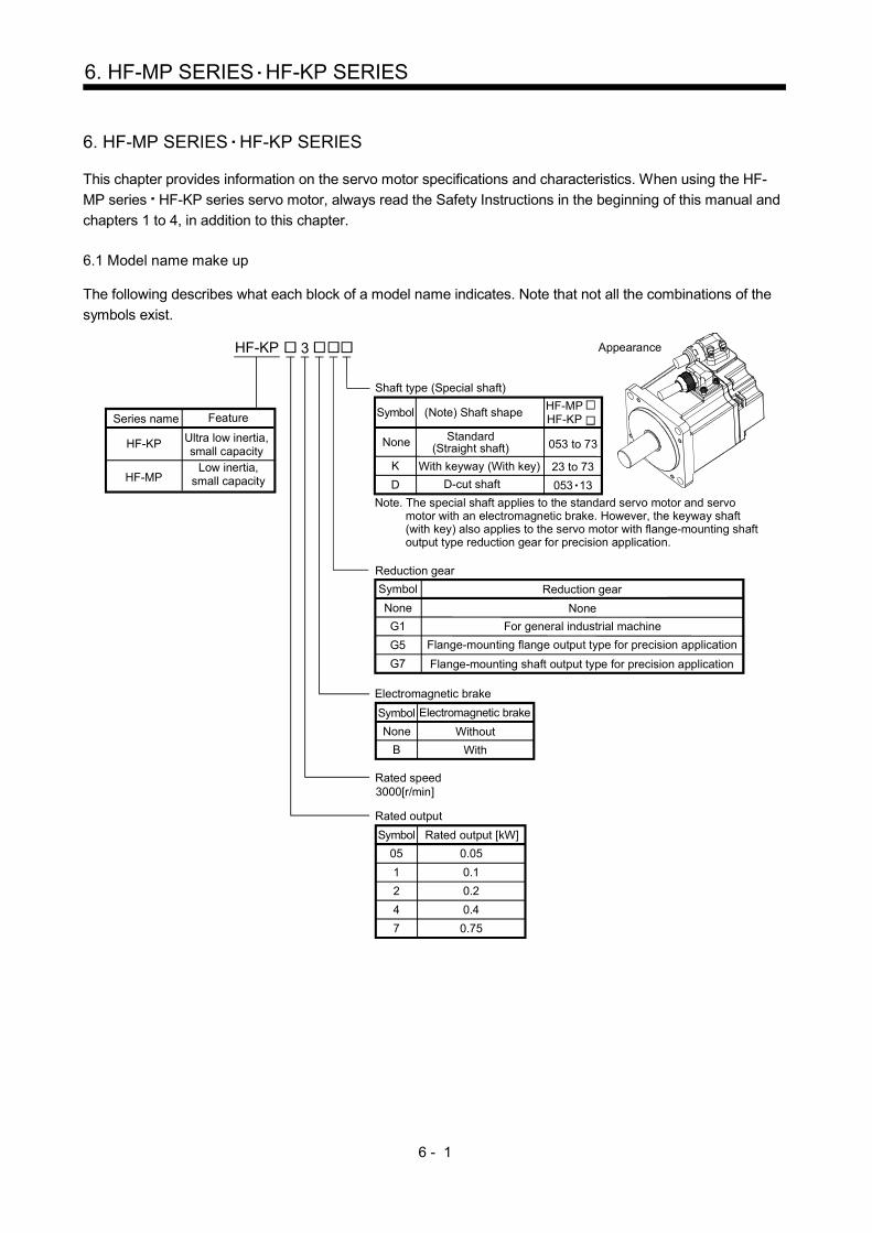
6 - 1
6. HF-MP SERIES HF-KP SERIES
6. HF-MP SERIES HF-KP SERIES
This chapter provides information on the servo motor specifications and characteristics. When using the HF-
MP series HF-KP series servo motor, always read the Safety Instructions in the beginning of this manual and
chapters 1 to 4, in addition to this chapter.
6.1 Model name make up
The following describes what each block of a model name indicates. Note that not all the combinations of the
symbols exist.
3000[r/min]
B
05 0.05
1 0.1
2 0.2
4 0.4
7 0.75
K
D
053 to 73
23 to 73
053 13
HF-MPHF-KP
HF-KP 3
Shaft type (Special shaft)
Symbol (Note) Shaft shape
Standard (Straight shaft)
With keyway (With key)
D-cut shaft
None
Symbol Electromagnetic brake
None Without
With
Rated output
Rated output [kW]Symbol
Rated speed
Appearance
Symbol
Reduction gear
G1 For general industrial machine
Flange-mounting flange output type for precision application
Flange-mounting shaft output type for precision application
Reduction gear
None
G5
G7
None
Feature
Ultra low inertia, small capacity
Low inertia, small capacityHF-MP
HF-KP
Series name
Note. The special shaft applies to the standard servo motor and servo motor with an electromagnetic brake. However, the keyway shaft (with key) also applies to the servo motor with flange-mounting shaft output type reduction gear for precision application.
Electromagnetic brake

6 - 2
6. HF-MP SERIES HF-KP SERIES
6.2 Standard specifications
6.2.1 Standard specifications list
Servo motor Item
HF-MP series (Ultra-low inertia small capacity)
HF-KP series (Low inertia small capacity)
053 13 23 43 73 053 13 23 43 73
Applicable servo amplifier/drive unit
MR-J3- A/B/B-RJ006/T 10 20 40 70 10 20 40 70
MR-J3- A1/B1/B1-RJ006/T1 10 20 40 10 20 40
Continuous running duty (Note 1)
Rated output [kW] 0.05 0.1 0.2 0.4 0.75 0.05 0.1 0.2 0.4 0.75
Rated torque [N m] 0.16 0.32 0.64 1.3 2.4 0.16 0.32 0.64 1.3 2.4
[oz in] 22.7 45.3 90.6 184 340 22.7 45.3 90.6 184 340
Rated speed (Note 1) [r/min] 3000 3000
Maximum speed (Note 10) [r/min] 6000 6000
Instantaneous permissible speed [r/min] 6900 6900
Maximum torque Values in parentheses are at the maximum torque of 350 (note 11)
[N m] 0.48 0.95 1.9 3.8 7.2 0.48
(0.56) 0.95
(1.11) 1.9
(2.23) 3.8
(4.46) 7.2
(8.36)
[oz in] 68.0 135 269 538 1020 68.0
(79.3) 135
(157) 269
(316) 538
(632) 1020
(1180)
Power rate at continuous rated torque [kW/s] 13.3 31.7 46.1 111.6 95.5 4.87 11.5 16.9 38.6 39.9
Inertia moment (Note 3) J [ 10-4kg m2] 0.019 0.032 0.088 0.15 0.60 0.052 0.088 0.24 0.42 1.43
WK2 [oz in2] 0.104 0.175 0.481 0.82 3.28 0.284 0.481 1.31 2.30 7.82
Recommended ratio of load inertia moment to servo motor shaft inertia moment (Note 2, 10)
30 times or less 15 times or
less
24 times
or less
22 times
or less
15 times
or less
Power supply capacity Refer to "Power supply equipment capacity and generated loss of servo
amplifiers" in Servo Amplifier Instruction Manual.
Rated current [A] 1.1 0.9 1.6 2.7 5.6 0.9 0.8 1.4 2.7 5.2
Maximum current Values in parentheses are at the maximum torque of 350 (note 11)
[A] 3.2 2.8 5.0 8.6 16.7 2.7
(3.1) 2.4
(2.8) 4.2
(4.9) 8.1
(9.5) 15.6
(18.2)
Speed/position detector Encoder common to absolute position and incremental detection systems
(Resolution per servo motor 1 rotation: 262144pulse/rev)
Accessory
Insulation class 130(B)
Structure Totally - enclosed, natural-cooling (IP rating: IP65 (Note 4, 9))
Environmental conditions (Note 5)
Ambient temperature
Operation [ ] 0 to 40 (non-freezing)
[ ] 32 to 104 (non-freezing)
Storage [ ] 15 to 70 (non-freezing)
[ ] 5 to 158 (non-freezing)
Ambient humidity
Operation 10 to 80%RH (non-condensing)
Storage 10 to 90%RH (non-condensing)
Ambience Indoors (no direct sunlight)
Free from corrosive gas, flammable gas, oil mist, dust and dirt.
Altitude Max.1000m above sea level
Vibration resistance (Note 6)
[m/s2] X, Y: 49
Vibration rank (Note 7) V10
Permissible load for the shaft (Note 8, 10)
L [mm] 25 30 40 25 30 40
Radial [N] 88 245 392 88 245 392
[lb] 19.8 55.1 88.1 19.8 55.1 88.1
Thrust [N] 59 98 147 59 98 147
[lb] 13.3 22.0 33.0 13.3 22.0 33.0
Mass (Note 3) [kg] 0.35 0.56 0.94 1.5 2.9 0.35 0.56 0.94 1.5 2.9
[lb] 0.77 1.24 2.07 3.31 6.39 0.77 1.24 2.07 3.31 6.39
Note 1. When the power supply voltage drops, the out.
2. If the load inertia moment ratio exceeds the indicated value, please consult us.
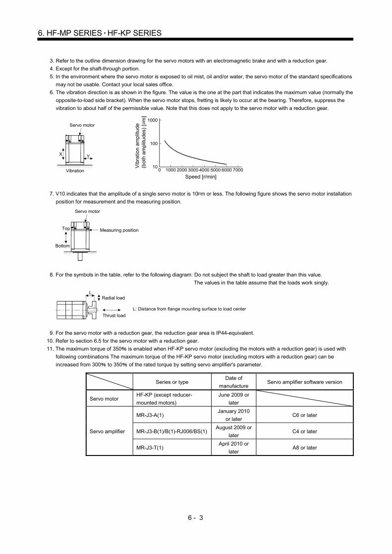
6 - 3
6. HF-MP SERIES HF-KP SERIES
3. Refer to the outline dimension drawing for the servo motors with an electromagnetic brake and with a reduction gear.
4. Except for the shaft-through portion.
5. In the environment where the servo motor is exposed to oil mist, oil and/or water, the servo motor of the standard specifications
may not be usable. Contact your local sales office.
6. The vibration direction is as shown in the figure. The value is the one at the part that indicates the maximum value (normally the
opposite-to-load side bracket). When the servo motor stops, fretting is likely to occur at the bearing. Therefore, suppress the
vibration to about half of the permissible value. Note that this does not apply to the servo motor with a reduction gear.
YX
Servo motor
Vibration Speed [r/min]
0 1000 2000 3000 4000 5000 6000 700010
100
1000
Vib
ratio
n am
plitu
de
(bot
h am
plitu
des)
[ m
]
7. V10 indicates that the amplitude of a single servo motor is 10 m or less. The following figure shows the servo motor installation
position for measurement and the measuring position.
Servo motor
Top
Bottom
Measuring position
8. For the symbols in the table, refer to the following diagram: Do not subject the shaft to load greater than this value.
The values in the table assume that the loads work singly.
LRadial load
Thrust load
L: Distance from flange mounting surface to load center
9. For the servo motor with a reduction gear, the reduction gear area is IP44-equivalent.
10. Refer to section 6.5 for the servo motor with a reduction gear.
11. The maximum torque of 350 is enabled when HF-KP servo motor (excluding the motors with a reduction gear) is used with
following combinations The maximum torque of the HF-KP servo motor (excluding motors with a reduction gear) can be
increased from 300 to 350 of the rated torque by setting servo amplifier's parameter.
Series or type Date of
manufacture Servo amplifier software version
Servo motor HF-KP (except reducer-
mounted motors)
June 2009 or
later
Servo amplifier
MR-J3-A(1) January 2010
or later C6 or later
MR-J3-B(1)/B(1)-RJ006/BS(1) August 2009 or
later C4 or later
MR-J3-T(1) April 2010 or
later A8 or later

6 - 4
6. HF-MP SERIES HF-KP SERIES
6.2.2 Torque characteristics
POINT
For the system where the unbalanced torque occurs, such as a vertical axis
system, the unbalanced torque of the machine should be kept at 70% or less of
the rated torque.
When the power input of the servo amplifier are 3-phase 200VAC or 1-phase 230VAC, the torque
characteristic is indicated by the heavy line.
For the 1-phase 200VAC power supply, part of the torque characteristic is indicated by the thin line. For the 1-
phase 100VAC power supply, part of the torque characteristic is indicated by the broken line.
10002000
30004000
50006000
Speed [r/min]
Continuousrunning range
Short-durationrunning range
Tor
que
[N•m
]
0.3
0.4
0.5
0.6
0.1
0.2
[HF-MP053]
00
[HF-MP13]
10002000
30004000
50006000
Speed [r/min]
Continuousrunning range
Short-durationrunning range
Tor
que
[N•m
]
0.2
0.4
0.6
0.8
1
1.2
00
[HF-MP23]
10002000
30004000
50006000
0
Speed [r/min]
Continuousrunning range
Short-durationrunning rangeT
orqu
e [N
•m]
0.5
1
1.5
2
0
2.5
[HF-MP43]
10002000
30004000
50006000
Speed [r/min]
Continuousrunning range
Short-durationrunning rangeT
orqu
e [N
•m]
00
1
2
3
4
0.5
1.5
2.5
3.5
4.5
[HF-MP73]
10002000
30004000
50006000
00
1
2
3
4
5
6
7
8
Speed [r/min]
Continuousrunning range
Short-durationrunning range
Tor
que
[N•m
]
[HF-KP053]
10002000
30004000
50006000
0
(Note)
Speed [r/min]
Continuousrunning range
Short-durationrunning range
Tor
que
[N•m
]
0
0.1
0.2
0.3
0.4
0.5
0.7
0.6
[HF-KP13]
10002000
30004000
50006000
0
(Note)
Speed [r/min]
Continuousrunning range
Short-durationrunning range
Tor
que
[N•m
]
0
0.2
0.4
0.6
0.8
1.2
1.4
1
[HF-KP23]
10002000
30004000
50006000
0
(Note)
0.5
1
1.5
2
2.5
0
Speed [r/min]
Continuousrunning range
Short-durationrunning range
Tor
que
[N•m
]
[HF-KP43]
10002000
30004000
50006000
0
(Note)
Speed [r/min]
Continuousrunning range
Short-durationrunning range
Tor
que
[N•m
]
0.5
1
1.5
2
2.5
3
3.5
4
4.5
5
0
[HF-KP73]
10002000
30004000
50006000
0
(Note)
Speed [r/min]
Continuousrunning range
Short-durationrunning range
Tor
que
[N•m
]
0
1
2
3
4
5
6
7
8
9
Note. Value at the maximum torque 350 .
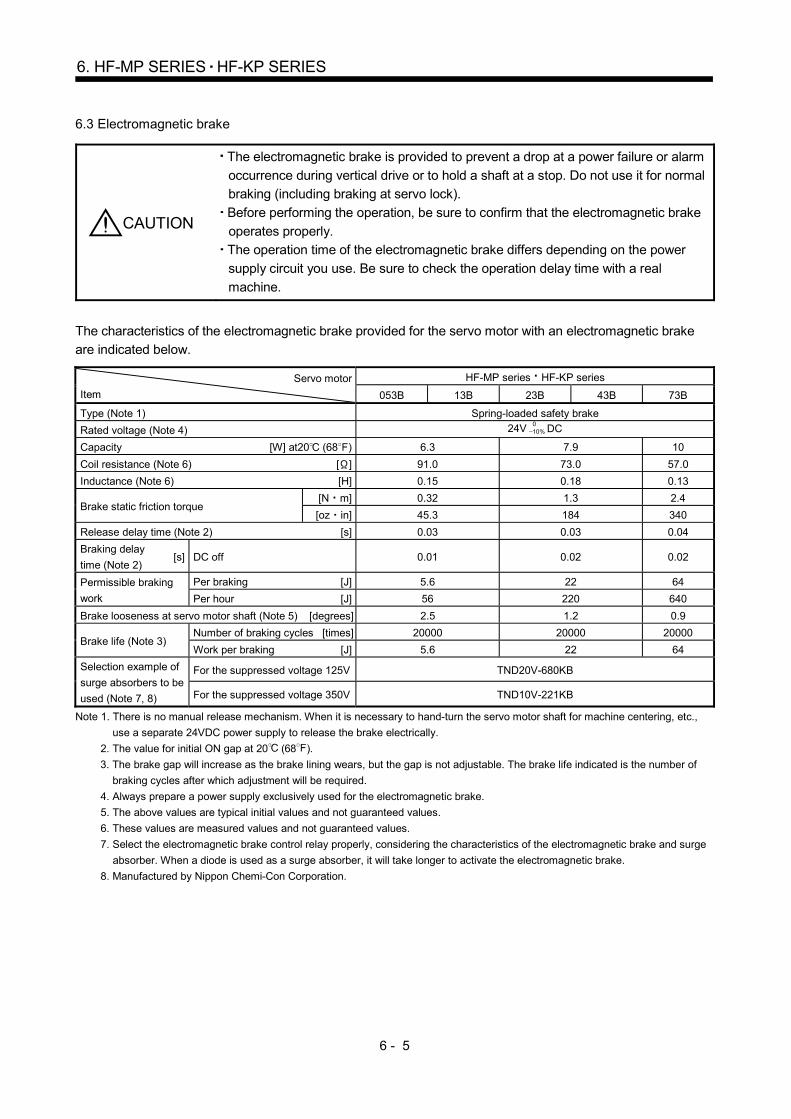
6 - 5
6. HF-MP SERIES HF-KP SERIES
6.3 Electromagnetic brake
CAUTION
The electromagnetic brake is provided to prevent a drop at a power failure or alarm
occurrence during vertical drive or to hold a shaft at a stop. Do not use it for normal
braking (including braking at servo lock).
Before performing the operation, be sure to confirm that the electromagnetic brake
operates properly.
The operation time of the electromagnetic brake differs depending on the power
supply circuit you use. Be sure to check the operation delay time with a real
machine.
The characteristics of the electromagnetic brake provided for the servo motor with an electromagnetic brake
are indicated below.
Servo motor
Item
HF-MP series HF-KP series
053B 13B 23B 43B 73B
Type (Note 1) Spring-loaded safety brake
Rated voltage (Note 4) 24V 010% DC
Capacity [W] at20 (68 ) 6.3 7.9 10
Coil resistance (Note 6) [ ] 91.0 73.0 57.0
Inductance (Note 6) [H] 0.15 0.18 0.13
Brake static friction torque [N m] 0.32 1.3 2.4
[oz in] 45.3 184 340
Release delay time (Note 2) [s] 0.03 0.03 0.04
Braking delay
time (Note 2) [s] DC off 0.01 0.02 0.02
Permissible braking
work
Per braking [J] 5.6 22 64
Per hour [J] 56 220 640
Brake looseness at servo motor shaft (Note 5) [degrees] 2.5 1.2 0.9
Brake life (Note 3) Number of braking cycles [times] 20000 20000 20000
Work per braking [J] 5.6 22 64
Selection example of
surge absorbers to be
used (Note 7, 8)
For the suppressed voltage 125V TND20V-680KB
For the suppressed voltage 350V TND10V-221KB
Note 1. There is no manual release mechanism. When it is necessary to hand-turn the servo motor shaft for machine centering, etc.,
use a separate 24VDC power supply to release the brake electrically.
2. The value for initial ON gap at 20 (68 ).
3. The brake gap will increase as the brake lining wears, but the gap is not adjustable. The brake life indicated is the number of
braking cycles after which adjustment will be required.
4. Always prepare a power supply exclusively used for the electromagnetic brake.
5. The above values are typical initial values and not guaranteed values.
6. These values are measured values and not guaranteed values.
7. Select the electromagnetic brake control relay properly, considering the characteristics of the electromagnetic brake and surge
absorber. When a diode is used as a surge absorber, it will take longer to activate the electromagnetic brake.
8. Manufactured by Nippon Chemi-Con Corporation.

6 - 6
6. HF-MP SERIES HF-KP SERIES
6.4 Servo motors with special shafts
The servo motors with special shafts indicated by the symbols (K D) in the table are available. K and D are
the symbols attached to the servo motor model names.
Refer to section 6.5.2 (4) for geared servo motors with special shaft.
Servo motor Shaft shape
Keyway shaft (with key) D cut shaft
HF-MP053(B) 13(B)
HF-KP053(B) 13(B) D
HF-MP23(B) to 73(B)
HF-KP23(B) to 73(B) K
6.4.1 Keyway shaft (with key)
Q
A
A
QK
R
T
W
U
S
QL
Y
Section A-A
[Unit: mm]
Servo motor
Variable dimensions
S R Q W QK QL U T Y
HF-
MP23(B)K
43(B)K
HF-
KP23(B)K
43(B)K
14h6 30 27 5 20 3 3 5 M4
Depth 15
HF-
MP73(B)K
HF-
KP73(B)K
19h6 40 37 6 25 5 3.5 6 M5
Depth 20
6.4.2 D cut shaft
[Unit: mm]
8h6
25
21.520.5 1
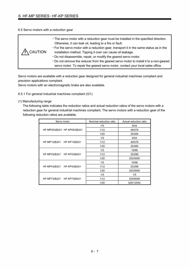
6 - 7
6. HF-MP SERIES HF-KP SERIES
6.5 Servo motors with a reduction gear
CAUTION
The servo motor with a reduction gear must be installed in the specified direction.
Otherwise, it can leak oil, leading to a fire or fault.
For the servo motor with a reduction gear, transport it in the same status as in the
installation method. Tipping it over can cause oil leakage.
Do not disassemble, repair, or modify the geared servo motor.
Do not remove the reducer from the geared servo motor to install it to a non-geared
servo motor. To repair the geared servo motor, contact your local sales office.
Servo motors are available with a reduction gear designed for general industrial machines compliant and
precision applications compliant.
Servo motors with an electromagnetic brake are also available.
6.5.1 For general industrial machines compliant (G1)
(1) Manufacturing range
The following table indicates the reduction ratios and actual reduction ratios of the servo motors with a
reduction gear for general industrial machines compliant. The servo motors with a reduction gear of the
following reduction ratios are available.
Servo motor Nominal reduction ratio Actual reduction ratio
HF-MP053(B)G1 HF-KP053(B)G1
1/5 9/44
1/12 49/576
1/20 25/484
HF-MP13(B)G1 HF-KP13(B)G1
1/5 9/44
1/12 49/576
1/20 25/484
HF-MP23(B)G1 HF-KP23(B)G1
1/5 19/96
1/12 25/288
1/20 253/5000
HF-MP43(B)G1 HF-KP43(B)G1
1/5 19/96
1/12 25/288
1/20 253/5000
HF-MP73(B)G1 HF-KP73(B)G1
1/5 1/5
1/12 525/6048
1/20 625/12544

6 - 8
6. HF-MP SERIES HF-KP SERIES
(2) Specifications
Item Description
Servo motor HF-KP (B)G1/HF-MP (B)G1 Mounting method Flange mounting Mounting direction In any directions Lubrication method Grease lubrication (Already packed) (Note 1) Output shaft rotating direction Same as the servo motor output shaft direction. With an electromagnetic brake Available Backlash (Note 4) 60 minutes or less at reduction gear output shaft
Permissible load inertia moment ratio (when converting into the servo motor shaft) (Note 2)
HF-KP When 50W 100W 750W used: 5 times or less When 200W 400W used: 7 times or less
HF-MP: 25 times or less Maximum torque Three times of the servo motor rated torque Maximum speed (servo motor shaft) 4500 r/min (instantaneous permissible speed: 5175 r/min) IP rating (reduction gear area) IP44 equivalent Reduction gear efficiency (Note 3) 40 to 75
Note 1. Already packed with grease. 2. If the above indicated value is exceeded, please contact your local sales office. 3. The reduction gear efficiency differs depending on the reduction ratio.
Also, it changes depending on the use conditions such as the output torque, speed and rotation, temperature, etc. The numerical value in the table is a typical value in the rated torque, rated speed and rotation and typical temperature, and not a guaranteed value.
4. The backlash can be converted: 1 min = 0.0167 ° (3) Permissible loads of servo motor shaft
The permissible radial load in the table is the value measured at the center of the reduction gear output
shaft. Q/2
Q
Q: Length of axis (Refer to section 6.8.3, 6.8.4)
Servo motor Reduction ratio
Permissible load (Note)
Permissible radial load
Permissible thrust load
[N] [lb] [N] [lb]
HF-MP053(B)G1 HF-KP053(B)G1
1/5 150 33.7 200 45.0
1/12 240 54.0 320 71.9
1/20 370 83.2 450 101
HF-MP13(B)G1 HF-KP13(B)G1
1/5 150 33.7 200 45.0
1/12 240 54.0 320 71.9
1/20 370 83.2 450 101
HF-MP23(B)G1 HF-KP23(B)G1
1/5 330 74.2 350 78.7
1/12 710 160 720 162
1/20 780 175 780 175
HF-MP43(B)G1 HF-KP43(B)G1
1/5 330 74.2 350 78.7
1/12 710 160 720 162
1/20 760 171 760 171
HF-MP73(B)G1 HF-KP73(B)G1
1/5 430 96.7 430 96.7
1/12 620 139 620 139
1/20 970 218 960 216
Note. The load above this value should not be applied to the shaft. The value in the table assumes that the load is applied independently.

6 - 9
6. HF-MP SERIES HF-KP SERIES
6.5.2 For precision applications compliant (G5/G7)
(1) Manufacturing range
The symbols (14A, 20A, 32A) in the following table indicate the model numbers of the reduction gears
assembled to the servo motors.
Servo motors with a reduction gear having the indicated reduction gear model numbers are available.
The reduction gear model number indicates of the reduction number model name HPG- -05...
Servo motor Reduction ratio
1/5 1/11 1/21 1/33 1/45
HF-MP053(B)G5 HF-KP053(B)G5
HF-MP053(B)G7 HF-KP053(B)G7
HF-MP13(B)G5 HF-KP13(B)G5
HF-MP13(B)G7 HF-KP13(B)G7
14A
HF-MP23(B)G5 HF-KP23(B)G5
HF-MP23(B)G7 HF-KP23(B)G7
20A
HF-MP43(B)G5 HF-KP43(B)G5
HF-MP43(B)G7 HF-KP43(B)G7
HF-MP73(B)G5 HF-KP73(B)G5
HF-MP73(B)G7 HF-KP73(B)G7
32A
(2) Specifications Item Description
Servo motor HF-MP (B)G5
HF-MP (B)G7
HF-KP (B)G5
HF-KP (B)G7
Mounting method Flange mounting
Mounting direction In any directions
Lubrication method Grease lubrication (Already packed) (Note 1)
Output shaft rotating direction Same as the servo motor output shaft direction.
With an electromagnetic brake Available
Backlash (Note 5) 3 minutes or less at reduction gear output shaft
Permissible load inertia moment ratio
(when converting into the servo motor
shaft) (Note 2)
25 times or less
50, 100 or 750W:
10 times or less
200 or 400W:
14 times or less
Maximum torque Three times of the servo motor rated torque
Maximum speed (servo motor shaft) 6000r/min (instantaneous permissible speed: 6900 r/min)
IP rating (reduction gear area) IP44 equivalent
Reduction gear efficiency (Note 3) 48 to 85% (Note 4)
Note 1. Already packed with grease.
2. If the above indicated value is exceeded, please contact your local sales office.
3. The reduction gear efficiency differs depending on the reduction ratio.
Also, it changes depending on the use conditions such as the output torque, speed and
rotation, temperature, etc. The numerical value in the table is a typical value in the rated
torque, rated speed and rotation and typical temperature, and not a guaranteed value.
4. The reduction gear efficiency of the HF-MP053 HF-KP053 is 12 to 34%.
5. The backlash can be converted: 1 min = 0.0167 °
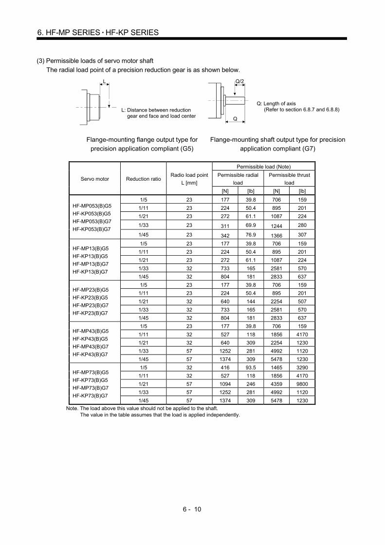
6 - 10
6. HF-MP SERIES HF-KP SERIES
(3) Permissible loads of servo motor shaft
The radial load point of a precision reduction gear is as shown below.
L
L: Distance between reduction gear end face and load center
Q/2
Q
Q: Length of axis (Refer to section 6.8.7 and 6.8.8)
Flange-mounting flange output type for
precision application compliant (G5)
Flange-mounting shaft output type for precision
application compliant (G7)
Servo motor Reduction ratio Radio load point
L [mm]
Permissible load (Note)
Permissible radial
load
Permissible thrust
load
[N] [lb] [N] [lb]
HF-MP053(B)G5
HF-KP053(B)G5
HF-MP053(B)G7
HF-KP053(B)G7
1/5 23 177 39.8 706 159
1/11 23 224 50.4 895 201
1/21 23 272 61.1 1087 224
1/33 23 311 69.9 1244 280
1/45 23 342 76.9 1366 307
HF-MP13(B)G5
HF-KP13(B)G5
HF-MP13(B)G7
HF-KP13(B)G7
1/5 23 177 39.8 706 159
1/11 23 224 50.4 895 201
1/21 23 272 61.1 1087 224
1/33 32 733 165 2581 570
1/45 32 804 181 2833 637
HF-MP23(B)G5
HF-KP23(B)G5
HF-MP23(B)G7
HF-KP23(B)G7
1/5 23 177 39.8 706 159
1/11 23 224 50.4 895 201
1/21 32 640 144 2254 507
1/33 32 733 165 2581 570
1/45 32 804 181 2833 637
HF-MP43(B)G5
HF-KP43(B)G5
HF-MP43(B)G7
HF-KP43(B)G7
1/5 23 177 39.8 706 159
1/11 32 527 118 1856 4170
1/21 32 640 309 2254 1230
1/33 57 1252 281 4992 1120
1/45 57 1374 309 5478 1230
HF-MP73(B)G5
HF-KP73(B)G5
HF-MP73(B)G7
HF-KP73(B)G7
1/5 32 416 93.5 1465 3290
1/11 32 527 118 1856 4170
1/21 57 1094 246 4359 9800
1/33 57 1252 281 4992 1120
1/45 57 1374 309 5478 1230
Note. The load above this value should not be applied to the shaft. The value in the table assumes that the load is applied independently.

6 - 11
6. HF-MP SERIES HF-KP SERIES
(4) Special shaft servo motors
Servo motors with special shafts having keyway (with single pointed keys) are available for the flange-
mounting shaft output type for precision applications compliant (G7).
[Unit: mm]
Servo motor Reduction gear
model number Q S W T QK U Y
HC-MP (B)G7K
HC-KP (B)G7K
14A 28 16h7 5 5 25 3 M4
Depth 8
20A 42 25h7 8 7 36 4 M6
Depth 12
32A 82 40h7 12 8 70 5 M10
Depth 20
UApprox. Q
QK
W
T
S
Y
6.6 Wiring option
Connecter sets to use in power supply connector or brake connector are available as option.
For details of each cable, cable and connector set to use in wiring to encoder, refer to the Servo Amplifier
Instruction Manual for using.
Make sure to use the following power supply cable for conforming to the EN compliant.
Servo motor Servo motor power cable Electromagnetic brake cable
HF-MP
HF-KP
MR-PWS1CBL M-A1-L MR-BKS1CBL M-A1-L
MR-PWS1CBL M-A1-H MR-BKS1CBL M-A1-H
MR-PWS1CBL M-A2-L MR-BKS1CBL M-A2-L
MR-PWS1CBL M-A2-H MR-BKS1CBL M-A2-H
MR-PWS2CBL03M-A1-L MR-BKS2CBL03M-A1-L
MR-PWS2CBL03M-A2-L MR-BKS2CBL03M-A2-L

6 - 12
6. HF-MP SERIES HF-KP SERIES
6.7 Connector installation
If the connector is not fixed securely, it may come off or may not produce a splash-proof effect during operation.
To achieve the IP rating IP65, pay attention to the following points and install the connectors.
(1) When screwing the connector, hold the connector still and gradually tighten the screws in a crisscross
pattern.
1)
4)
3)
2)
Tightening sequence
1) 2) 3) 4)
Connector for power supply, connector for encoder
Tightening order
1) 2)
1)
2)
Connector for brake
(2) Tighten the screws evenly.
Tightening torques are as indicated below.
Connector for brakeScrew size M2Tightening torque 0.2N m
Connector for power supplyScrew size M2Tightening torque 0.2N m
Connector for encoderScrew size M2Tightening torque 0.1N m
(3) The servo motor fitting part of each connector is provided with a splash-proof seal (O ring). When installing
the connector, use care to prevent the seal (O ring) from dropping and being pinched. If the seal (O ring)
has dropped or is pinched, a splash-proof effect is not produced.

6 - 13
6. HF-MP SERIES HF-KP SERIES
6.8 Outline dimension drawings
The outer frame of the reduction gear is a material surface such as casting. Its actual dimensions may be 1 to
3mm larger than the drawing dimensions. Design the machine side with allowances.
When running the cables to the load side, take care to avoid interference with the machine. The dimensions
without tolerances are reference dimensions.
Inertia moment on the table is the value calculated by converting the total value of inertia moment for servo
motor, electromagnetic brake and decelerator with servo motor shaft.
6.8.1 Standard (without an electromagnetic brake, without a reduction gear)
Model Output
[W]
Inertia moment
J [ 10-4kg m2]
(WK2 [oz in2])
Mass
[kg] ([lb])
HF-MP053 50 0.019 (0.104) 0.35 (0.77)
HF-KP053 50 0.052 (0.284) 0.35 (0.77)
[Unit: mm]
40
45
6.4
27.5
46
25
2.5
27.4
4.9
Motor plate
9.5
11.7
Bottom
11.713.9
20.720.5
Caution plate
13.7
21.5
5
19.2
10.1
21.5
66.4
24.5
High temperaturecaution plate
Motor plate
Power supply connector
Encoder connector
Power supplyconnector
19.2
11.711.7 9.5
21.5Encoder connector
7
9 Opposite-to-load side
3
4
1
2
Power supply connector pin connection list
BC25946*
Top
(Opposite side)
Bottom
TopTop
Top
2- 4.5 mounting hole
Use hexagon sockethead cap screw
Bottom
2
34
Pin No.1
U
VW
Application (Earth)
Bottom
TUV plate
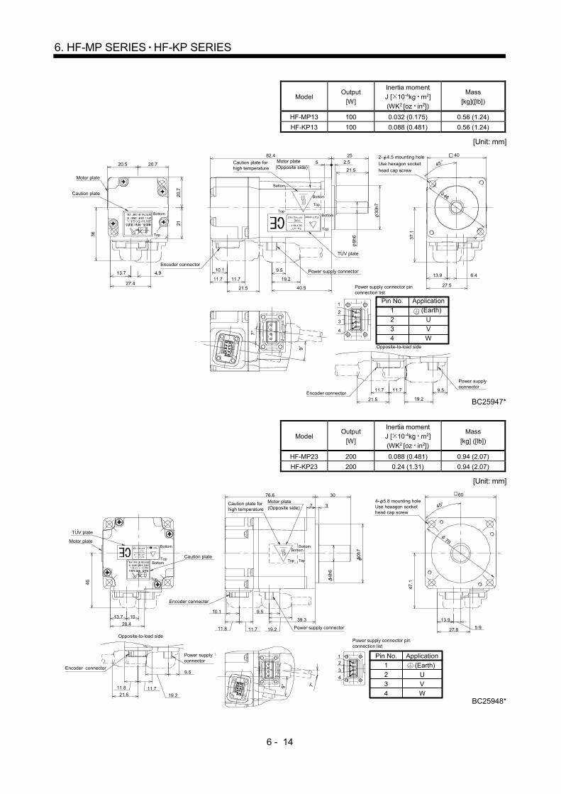
6 - 14
6. HF-MP SERIES HF-KP SERIES
Model Output
[W]
Inertia moment
J [ 10-4kg m2]
(WK2 [oz in2])
Mass
[kg]([lb])
HF-MP13 100 0.032 (0.175) 0.56 (1.24)
HF-KP13 100 0.088 (0.481) 0.56 (1.24)
[Unit: mm]
40
45
37.1
6.4
27.5
46
252.5
27.4
4.99.5
11.7
8h6
30h7
11.713.9
20.720.5
Caution plate
21
13.7
21.5
5
20.7
36
7
19.2
10.1
21.5
9
40.5
82.4
Power supply connector
Encoder connector
Encoder connector
Power supplyconnector
19.2
11.711.7 9.5
21.5 BC25947*
2- 4.5 mounting hole
Use hexagon sockethead cap screw
Bottom
Bottom
Top
Top
Caution plate forhigh temperature
Motor plate(Opposite side)
Bottom
Top
Motor plate
Opposite-to-load side
Bottom
Top
3
4
1
2
Power supply connector pinconnection list
42
31
2
3
4
Pin No.
1
U
V
W
Application
(Earth)
TUV plate
Model Output
[W]
Inertia moment
J [ 10-4kg m2]
(WK2 [oz in2])
Mass
[kg] ([lb])
HF-MP23 200 0.088 (0.481) 0.94 (2.07)
HF-KP23 200 0.24 (1.31) 0.94 (2.07)
[Unit: mm]
Caution plate forhigh temperature
30
50h7
14h6
60
45°
11.8
46
47.1
70
5.927.8
13.928.4
13.7 109.5
9°
19.211.7
7 3
10.1
7°
76.6
39.3
Caution plate
Encoder connector
Power supply connector
BC25948*
�Power supply connector
9.5Encoder connector
21.5
11.8 11.7
19.2
12
3
4
Power supply connector pinconnection list
12
34
Opposite-to-load side
Motor plateBottom
TopBottom
Top
4- 5.8 mounting holeUse hexagon sockethead cap screw
BottomBottom
TopTop
Motor plate(Opposite side)
2
3
4
Pin No.
1
U
V
W
Application
(Earth)
TUV plate
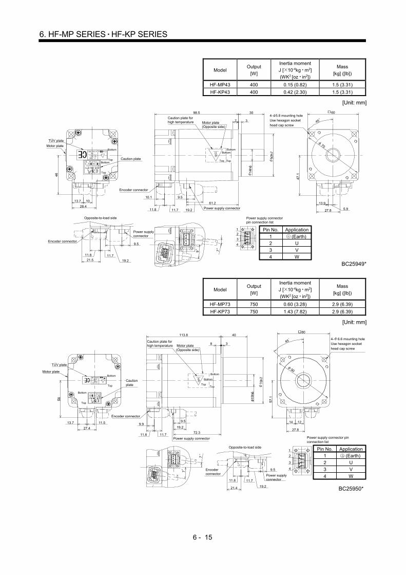
6 - 15
6. HF-MP SERIES HF-KP SERIES
Model Output
[W]
Inertia moment
J [ 10-4kg m2]
(WK2 [oz in2])
Mass
[kg] ([lb])
HF-MP43 400 0.15 (0.82) 1.5 (3.31)
HF-KP43 400 0.42 (2.30) 1.5 (3.31)
[Unit: mm]
2
3
4
Pin No.
1
U
V
W
Application
(Earth)
30 60
45
11.8
70
5.927.8
13.928.4
13.7 109.5
9
19.211.7
7 3
10.1
7
98.5
61.2
Caution plate
Power supply connector
Encoder connector
12
3
4
Power supply connectorpin connection list
19.2
11.721.5
11.8
9.5Encoder connector
BC25949*
Motor plate
Opposite-to-load side
Power supplyconnector
4- 5.8 mounting holeUse hexagon socket
head cap screw
BottomBottom
TopTop
Bottom
TopBottom
Top
Motor plate(Opposite side)
Caution plate forhigh temperature
TUV plate
Model Output
[W]
Inertia moment
J [ 10-4kg m2]
(WK2 [oz in2])
Mass
[kg] ([lb])
HF-MP73 750 0.60 (3.28) 2.9 (6.39)
HF-KP73 750 1.43 (7.82) 2.9 (6.39)
[Unit: mm]
2
3
4
Pin No.
1
U
V
W
Application
(Earth)
TUV plate
Cautionplate
Power supply connector
Encoder connector
Encoderconnector
Motor plate
Opposite-to-load side
4- 6.6 mounting holeUse hexagon socket
head cap screw
Top
Bottom
Top
BottomBottom
Top
Bottom
Top
Motor plate(Opposite side)
Caution plate forhigh temperature
113.8 40
3
80
90
45
12
72.311.8
9.5
27.4 27.8
14
8
11.5
11.7
13.7
7
7
9.919.2
19.2
11.7
21.4
11.8
9.5
Power supplyconnector
1
2
3
4
BC25950*
Power supply connector pinconnection list
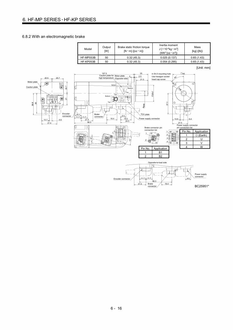
6 - 16
6. HF-MP SERIES HF-KP SERIES
6.8.2 With an electromagnetic brake
Model Output
[W]
Brake static friction torque
[N m] ([oz in])
Inertia moment
J [ 10-4kg m2]
(WK2 [oz in2])
Mass
[kg] ([lb])
HF-MP053B 50 0.32 (45.3) 0.025 (0.137) 0.65 (1.43)
HF-KP053B 50 0.32 (45.3) 0.054 (0.295) 0.65 (1.43)
[Unit: mm]
Encoderconnector
Motor plate
4- 4.5 mounting holeUse hexagon socket
head cap screw
Bottom
Bottom
TopTop
Bottom
Top
Motor plate(Opposite side)
Caution plate forhigh temperature
Brakeconnector
Opposite-to-load side
Bottom
Top
40
45
46
6.413.9
27.5
25
2.5
4.9
27.4
9
9.511.7 11.7
13.7
20.720.5
Caution plate
21.5
5
58.3
19.221.5
710.1
18.4
13
107.5
24.5Power supply connector
BC25951*
4
1
2
3
Brake connector pinconnection list
2
1
Encoder connector
21.5
Power supplyconnector
18.458.3
11.7 11.7 9.5
Power supply connectorpin connection list
Brakeconnector
2
3
4
Pin No.
1
U
V
W
Application
(Earth)
B12
Pin No.
1B2
Application
TUV plate
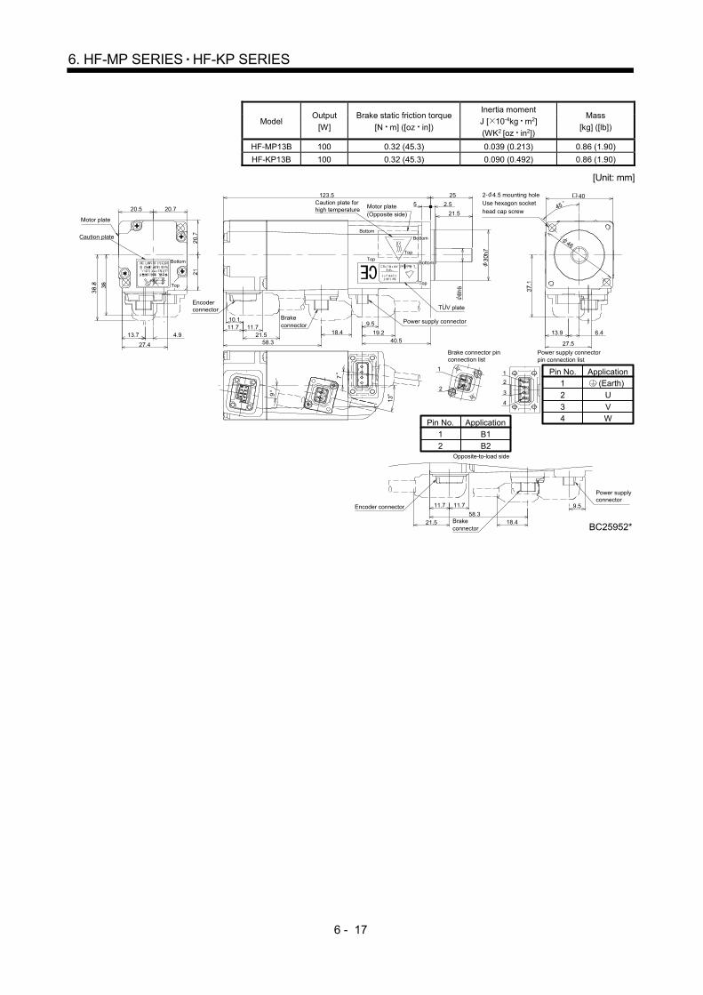
6 - 17
6. HF-MP SERIES HF-KP SERIES
Model Output
[W]
Brake static friction torque
[N m] ([oz in])
Inertia moment
J [ 10-4kg m2]
(WK2 [oz in2])
Mass
[kg] ([lb])
HF-MP13B 100 0.32 (45.3) 0.039 (0.213) 0.86 (1.90)
HF-KP13B 100 0.32 (45.3) 0.090 (0.492) 0.86 (1.90)
[Unit: mm]
B1
2
Pin No.
1
B2
Application
2
34
Pin No.1
U
VW
Application (Earth)
Top
Encoderconnector
Motor plate
2- 4.5 mounting holeUse hexagon sockethead cap screw
Bottom
Bottom
Top
TopBottom
Top
Motor plate(Opposite side)
Caution plate forhigh temperature
Opposite-to-load side
Caution plate
Power supply connector
Brake connector pinconnection list
Encoder connector
Power supplyconnector
Power supply connectorpin connection list
Brakeconnector
Brakeconnector
Bottom
40
45
46
6.413.9
27.5
25
2.5
4.9
27.4
9
9.511.7 11.7
13.7
20.720.521.5
5
58.3
19.221.57
10.1
18.4
13
123.5
40.5
BC25952*
4
1
2
32
1
58.321.5
11.7 11.7
18.4
9.5
TUV plate

6 - 18
6. HF-MP SERIES HF-KP SERIES
Model Output
[W]
Brake static friction
torque [N m] ([oz in])
Inertia moment
J [ 10-4kg m2]
(WK2 [oz in2])
Mass
[kg] ([lb])
HF-MP23B 200 1.3 (184) 0.12 (0.656) 1.6(3.53)
HF-KP23B 200 1.3 (184) 0.31 (1.70) 1.6(3.53)
[Unit: mm]
Opposite-to-load side
2
34
Pin No.
1
U
VW
Application
(Earth)
B12
Pin No.
1B2
Application
30 60
45
11.8
70
57.8
9.5
5.9
13.91013.7
21.528.427.8
11.7
13.5
37
79
19.2
10.1
116.1
39.3
Cautionplate
Power supply connector
Brake connector
BC25953*
12
34
1
2
18.311.8 11.79.5
Power supplyconnector
57.8
Encoder connector
21.5
Brake connector
Power supply connector pinconnection list
Brake connector pinconnection list
Encoderconnector
Bottom
TopBottom
Top
Motor plate
Caution plate forhigh temperature
Motor plate(Opposite side)
Bottom
Top
Bottom
Top
4- 5.8 mounting holeUse hexagon sockethead cap screw
TUV plate

6 - 19
6. HF-MP SERIES HF-KP SERIES
Model Output
[W]
Brake static friction torque
[N m] ([oz in])
Inertia moment
J [ 10-4kg m2]
(WK2 [oz in2])
Mass
[kg] ([lb])
HF-MP43B 400 1.3 (184) 0.18 (0.984) 2.1 (4.63)
HF-MP43B 400 1.3 (184) 0.50 (2.73) 2.1 (4.63)
[Unit: mm]
TUV plate
30 60
45
11.8
70
57.8
9.5
5.9
13.91013.7
21.528.427.8
11.7
13.5
37
79
19.2
10.1
138
61.2
BC25954*
12
34
1
2
Encoder connector
Brake connector57.811.8 11.7
21.5
18.39.5
Opposite-to-load side
B1
2
Pin No.
1
B2
Application
Cautionplate
Power supply connector
Brake connector
Power supplyconnector
Power supply connector pinconnection list
Brake connector pinconnection list
Encoderconnector
Bottom
TopBottom
Top
Motor plate
Caution plate forhigh temperature
Motor plate(Opposite side)
Bottom
Top
Bottom
Top
4- 5.8 mounting holeUse hexagon sockethead cap screw
2
3
4
Pin No.
1
U
V
W
Application
(Earth)
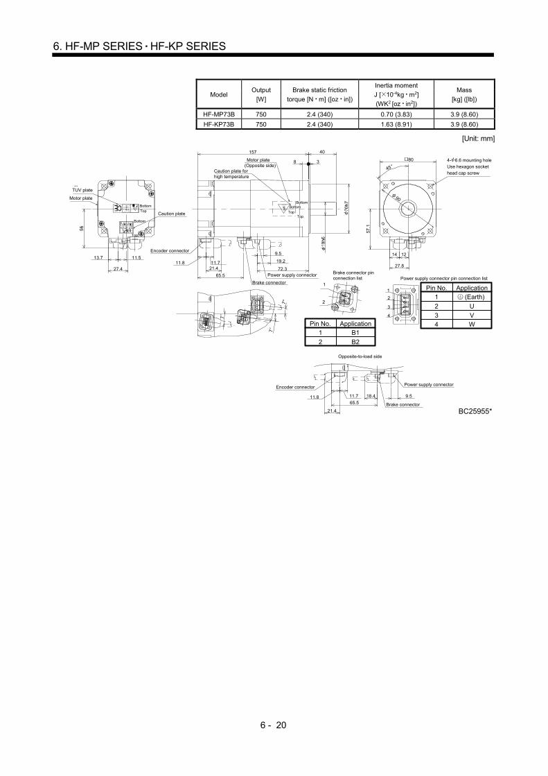
6 - 20
6. HF-MP SERIES HF-KP SERIES
Model Output
[W]
Brake static friction
torque [N m] ([oz in])
Inertia moment
J [ 10-4kg m2]
(WK2 [oz in2])
Mass
[kg] ([lb])
HF-MP73B 750 2.4 (340) 0.70 (3.83) 3.9 (8.60)
HF-KP73B 750 2.4 (340) 1.63 (8.91) 3.9 (8.60)
[Unit: mm]
B1
2
Pin No.1
B2
Application
80
157
8 3
45
90
40
14 12
27.827.4
11.513.711.8 11.7
7
9.5
72.365.5
7
7
19.2
21.4
Brake connector
Power supply connector
Encoder connector
Brake connector pinconnection list
1
3
4
2
1
2
Encoder connector
9.511.8
21.4
11.7
65.5
18.4
Power supply connector
Brake connector
BC25955*
TUV plate
Motor plate
Bottom
Caution plateTop
Bottom
Top
Motor plate(Opposite side)
Top
Bottom
Top
Bottom
Opposite-to-load side
4- 6.6 mounting holeUse hexagon sockethead cap screwCaution plate for
high temperature
Power supply connector pin connection list
2
34
Pin No.1
U
VW
Application (Earth)
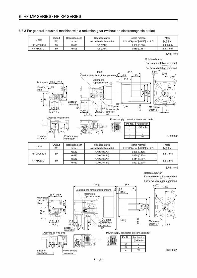
6 - 21
6. HF-MP SERIES HF-KP SERIES
6.8.3 For general industrial machine with a reduction gear (without an electromagnetic brake)
Model Output
[W]
Reduction gear
model
Reduction ratio
(Actual reduction ratio)
Inertia moment
J [ 10-4kg m2] (WK2 [oz in2])
Mass
[kg] ([lb])
HF-MP053G1 50 K6505 1/5 (9/44) 0.056 (0.306) 1.4 (3.09)
HF-KP053G1 50 K6505 1/5 (9/44) 0.089 (0.487) 1.4 (3.09)
[Unit: mm]
19.211.7 11.7
21.5
Opposite-to-load side
(Earth)
Power supply connector pin connection list
42
31
1234
ApplicationPin No.
1
2
34
U
VW BC26068*
45
For forward rotation command
For reverse rotation command
Rotation direction
6.4
M4 screwDepth 8
Encoder connector
Power supplyconnector
9.5
27.4
20.5
3637
.1
Motor plate
Caution plate
13.7 4.9
20.7
21
20.7
9.519.2
21.5
11.711.710.1
6.58
34.5
2560.5110.9
69
Power supply connector
TUV plate
Motor plate(Opposite side)
Caution plate for high temperature
Encoder connector
(R4)
Top
Bottom
Top
Bottom
Top
Bottom
Top
Bottom
16h
648 (5
0)
60h
7
4- 765
75
88
7
9
Model Output
[W]
Reduction gear
model
Reduction ratio
(Actual reduction ratio)
Inertia moment
J [ 10-4kg m2] (WK2 [oz in2])
Mass
[kg] ([lb])
HF-MP053G1 50 K6512 1/12 (49/576) 0.078 (0.426)
1.8 (3.97) K6520 1/20 (25/484) 0.060 (0.328)
HF-KP053G1 50 K6512 1/12 (49/576) 0.111 (0.607)
1.8 (3.97) K6520 1/20 (25/484) 0.093 (0.508)
[Unit: mm]
(Earth)
Power supply connector pin connection list
42
31
1234
ApplicationPin No.1
2
3
4
U
V
W
45
7
9
BC26069*
For forward rotation command
For reverse rotation command
Rotation direction
6.4
M4 screwDepth 8
19.221.5
Opposite-to-load side
11.7
Encoder connector
Power supplyconnector
9.511.7
27.4
21
20
.7
3637.1
20.5 20.7
Caution plate
4.913.7
8
11.7 19.2
10.1
21.5
60.5
34.5
6.5 25
87
128.9
Encoder connector
Power supply connector
TUV plate
Motor plate(Opposite side)
Caution plate for high temperature
(R4)9.5
11.7
Motor plate
Top
Bottom
Top
BottomTop
Bottom
Top
Bottom
16
h6
48
60h
7
4- 765
75
88
(
50)

6 - 22
6. HF-MP SERIES HF-KP SERIES
Model Output
[W]
Reduction gear
model
Reduction ratio
(Actual reduction ratio)
Inertia moment
J [ 10-4kg m2] (WK2 [oz in2])
Mass
[kg] ([lb])
HF-MP13G1 100 K6505 1/5 (9/44) 0.069 (0.377) 1.6 (3.53)
HF-KP13G1 100 K6505 1/5 (9/44) 0.125 (0.683) 1.6 (3.53)
[Unit: mm]
(Earth)
Power supply connector pin connection list
42
31
1234
ApplicationPin No.
12
3
4
U
V
W
45
7
9
19.2
11.7 11.721.5
Opposite-to-load side
BC26070*
654- 7
For forward rotation command
For reverse rotation command
Rotation direction
6.4
M4 screwDepth 8
Encoder connector
9.5
27.4
20.5
36
37.
1
Motor plate
Caution plate
13.7 4.9
20.7
21
20.7
Power supply connector
TUV plate
Caution plate for high temperature
Encoder connector
8
19.210.1
21.5
60.5
34.56.5 25
85
126.9
11.7 11.7
9.5 (R4)
Motor plate(Opposite side)
Top
Bottom Top
Bottom
Top
Bottom
16h6
48
60h
7
88
75
(
50)
Power supplyconnector
Model Output
[W]
Reduction gear
model
Reduction ratio
(Actual reduction ratio)
Inertia moment
J [ 10-4kg m2] (WK2 [oz in2])
Mass
[kg] ([lb])
HF-MP13G1 100 K6512 1/12 (49/576) 0.091 (0.498)
2.0 (4.19) K6520 1/20 (25/484) 0.073 (0.399)
HF-KP13G1 100 K6512 1/12 (49/576) 0.147 (0.804)
2.0 (4.19) K6520 1/20 (25/484) 0.129 (0.705)
[Unit: mm]
(Earth)
Power supply connector pin connection list
42
31
1234
ApplicationPin No.
12
34
U
VW
7
9
BC26071*
654- 7
For forward rotation command
For reverse rotation command
Rotation direction
6.4
M4 screwDepth 8
19.221.5
Opposite-to-load side
11.7
Encoder connector
9.511.7
27.4
21
20.7
3637.1
20.5 20.7
Caution plate
4.913.7
8
11.7 19.2
10.1
21.5
60.5
34.5
6.5 25
103
144.9
Power supply connector
TUV plate
Motor plate(Opposite side)
Caution plate for high temperature
16
h6
(
50)
60
h7
48
(R4)9.5
11.7
Motor plate
Top
BottomTopBottom
Top
BottomTop
Bottom 75
88
Encoder connector
Power supplyconnector
45

6 - 23
6. HF-MP SERIES HF-KP SERIES
Model Output
[W]
Reduction gear
model
Reduction ratio
(Actual reduction ratio)
Inertia moment
J [ 10-4kg m2] (WK2 [oz in2])
Mass
[kg] ([lb])
HF-MP23G1 200 K9005 1/5 (19/96) 0.248 (1.36) 3.3 (7.28)
HF-KP23G1 200 K9005 1/5 (19/96) 0.400 (2.19) 3.3 (7.28)
[Unit: mm]
(Earth)
Power supply connector pin connection list
42
31
1234
ApplicationPin No.
12
34
U
VW
45
BC26072*
7
9
21.5
Opposite-to-load side
Power supplyconnector
9.519.211.811.8
Encoder connector
TUV plate
46
28.4
10
47
.1
Motor plate Cautionplate
13.7
60
904- 9
For forward rotation command
For reverse rotation command
Rotation direction
5.9M6 screwDepth 12
114
Motor plate(Opposite side)
Caution plate for high temperature
25h
6
19.2
810
38
3574130.1
92.8
82h
7
73
10.1 Power supply connector
11.8
9.511.7
Encoder connector
Top
Bottom
Top
BottomTop
Bottom
Top
Bottom100
Model Output
[W]
Reduction gear
model
Reduction ratio
(Actual reduction ratio)
Inertia moment
J [ 10-4kg m2] (WK2 [oz in2])
Mass
[kg] ([lb])
HF-MP23G1 200 K9012 1/12 (25/288) 0.298 (1.63)
3.9 (8.60) K9020 1/20 (253/5000) 0.268 (1.47)
HF-KP23G1 200 K9012 1/12 (25/288) 0.450 (2.46)
3.9 (8.60) K9020 1/20 (253/5000) 0.420 (2.30)
[Unit: mm]
(Earth)
Power supply connector pin connection list
42
31
1234
ApplicationPin No.
1
2
34
U
VW
45
BC26073*
21.5
Opposite-to-load side
Power supplyconnector
19.211.8
11.7
Encoder connector
9.5
TUV plate
46
28.4
10
47
.1
Motor plate Cautionplate
13.7
60
904- 9
For forward rotation command
For reverse rotation command
Rotation direction
5.9M6 screwDepth 12
114
25h6
82h
773
Encoder connector
Motor plate(Opposite side)
Caution plate for high temperature
Power supply connector
10.1
19.2
810
38
3574150.1
112.8
9.5
11.8 11.7
TopBottom
Top
BottomTop
Bottom
Top
Bottom100
97

6 - 24
6. HF-MP SERIES HF-KP SERIES
Model Output
[W]
Reduction gear
model
Reduction ratio
(Actual reduction ratio)
Inertia moment
J [ 10-4kg m2] (WK2 [oz in2])
Mass
[kg] ([lb])
HF-MP43G1 400 K9005 1/5 (19/96) 0.300 (1.64) 3.9 (8.60)
HF-KP43G1 400 K9005 1/5 (19/96) 0.570 (3.12) 3.9 (8.60)
[Unit: mm]
(Earth)
Power supply connector pin connection list
42
31
1234
ApplicationPin No.
12
34
U
VW
45
10.111.8
BC26074*
21.5
Opposite-to-load side
Power supplyconnector
9.519.211.8
11.8
Encoder connector
90
For forward rotation command
For reverse rotation command
Rotation direction
5.9M6 screwDepth 12
114
25h6
82h7
73
Encoder connector
Motor plate(Opposite side)
Caution plate for high temperature
Power supply connector
19.2
38810 35
114.7
74152
9.5
TUV plate
46
28.4
10
47.1
Motor plate Cautionplate
13.7
60
Top
Bottom
Top
Bottom
4- 9
100
97
TopTop
BottomBottom
11.7
Model Output
[W]
Reduction gear
model
Reduction ratio
(Actual reduction ratio)
Inertia moment
J [ 10-4kg m2] ] (WK2 [oz in2])
Mass
[kg] ([lb])
HF-MP43G1 400 K9012 1/12 (25/288) 0.350 (1.91) 4.5 (9.92)
HF-KP43G1 400 K9012 1/12 (25/288) 0.620 (3.39) 4.5 (9.92)
[Unit: mm]
(Earth)
Power supply connector pin connection list
42
31
1234
ApplicationPin No.
12
34
U
VW
45
BC26075*
21.5
Opposite-to-load side
Power supplyconnector
9.519.211.8
11.7
Encoder connector
TUV plate
46
28.410
47.1
Motor plate Cautionplate
13.7
60
Top
Bottom
Top
Bottom
M6 screwDepth 12
4- 9
For forward rotation command
For reverse rotation command
Rotation direction
90
5.9
114
100
Encoder connector
Motor plate(Opposite side)
Caution plate for high temperature
Power supply connector
19.2
38810 35
134.7
74172
10.111.711.8
9.5
Top
Bottom
Top
Bottom
97
25
h6
82h7
73

6 - 25
6. HF-MP SERIES HF-KP SERIES
Model Output
[W]
Reduction gear
model
Reduction ratio
(Actual reduction ratio)
Inertia moment
J [ 10-4kg m2] (WK2 [oz in2])
Mass
[kg] ([lb])
HF-MP43G1 400 K10020 1/20 (253/5000) 0.660 (3.61) 5.6 (12.3)
HF-KP43G1 400 K10020 1/20 (253/5000) 0.930 (5.09) 5.6 (12.3)
[Unit: mm]
(Earth)
Power supply connector pin connection list
42
31
1234
ApplicationPin No.
12
34
U
VW
45
BC26076*
21.5
Opposite-to-load side
Power supplyconnector
9.519.211.8
11.7
Encoder connector
TUV plate
46
28.4
10
47
.1
Motor plate Cautionplate
13.7
60
M8 screwDepth 16
4- 9
For forward rotation command
For reverse rotation command
Rotation direction
100
132
115
Encoder connector
Motor plate(Opposite side)
Caution plate for high temperature
Power supply connector 3
2h6
86
95h7
10.1
10
90
10
138.2
39
50175.5
19.211.7
9.5
11.8
73
Top
Bottom
Top
Bottom
Top
Bottom
Top
Bottom
97
Model Output
[W]
Reduction gear
model
Reduction ratio
(Actual reduction ratio)
Inertia moment
J [ 10-4kg m2] (WK2 [oz in2])
Mass
[kg] ([lb])
HF-MP73G1 750 K10005 1/5 (1/5) 1.02 (5.58) 6.1 (13.4)
HF-KP73G1 750 K10005 1/5 (1/5) 1.85 (10.1) 6.1 (13.4)
[Unit: mm]
(Earth)
Power supply connector pin connection list
42
31
1234
ApplicationPin No.
1
2
34
U
VW
45
BC26077*
7
7
56
27.4
57.1
13.7 11.5
80
32
h6
86
95h
7
11.89.9
10
3950
90
10
137.3
178.8
11.79.519.2
73
Encoder connector
Motor plate (Opposite side)
Caution plate for high temperature
Power supply connector
TUV plateCautionplateMotor plate
4- 9
12
132
For forward rotation command
For reverse rotation command
Rotation direction
100
M8 screwDepth 16
Top
Bottom
Top
Bottom
TopBottom
Top
Bottom115
Opposite-to-load side
Power supplyconnector
Encoder connector
11.8
11.7
19.2
9.521.5
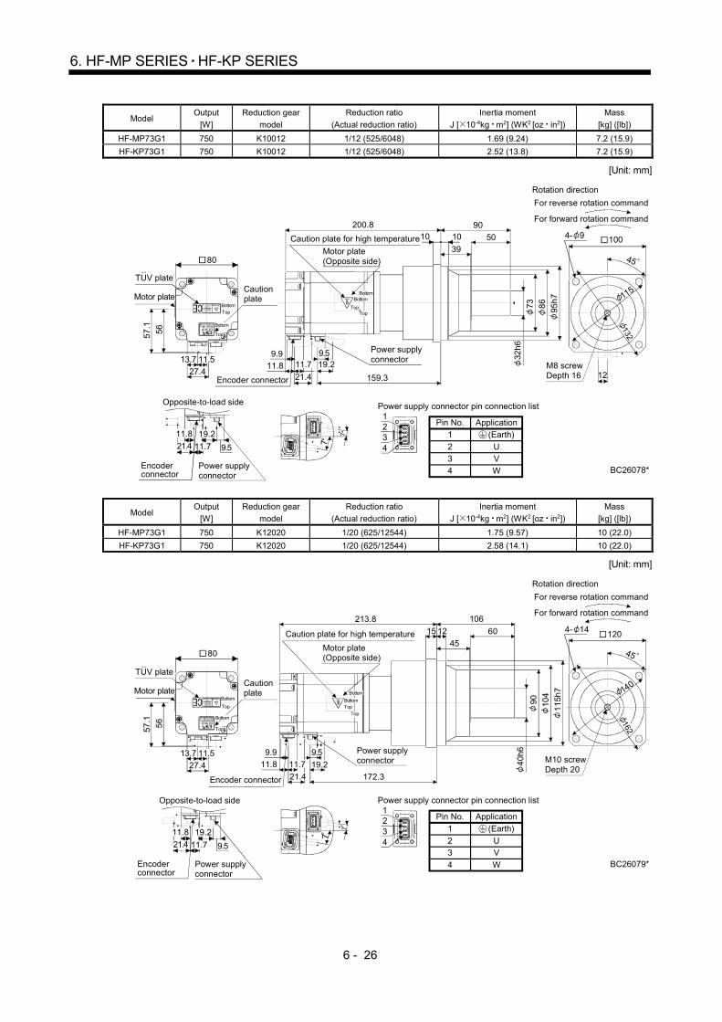
6 - 26
6. HF-MP SERIES HF-KP SERIES
Model Output
[W]
Reduction gear
model
Reduction ratio
(Actual reduction ratio)
Inertia moment
J [ 10-4kg m2] (WK2 [oz in2])
Mass
[kg] ([lb])
HF-MP73G1 750 K10012 1/12 (525/6048) 1.69 (9.24) 7.2 (15.9)
HF-KP73G1 750 K10012 1/12 (525/6048) 2.52 (13.8) 7.2 (15.9)
[Unit: mm]
(Earth)
Power supply connector pin connection list
42
31
1234
ApplicationPin No.
1
23
4
UV
W
45
BC26078*
7
7
56
27.4
57
.1
13.7 11.5
80
TopBottom
Top
Bottom
4- 9
12
132
For forward rotation command
For reverse rotation command
Rotation direction
100
115
TUV plateCautionplateMotor plate
M8 screwDepth 16
32h
6
86
95h
7
73
Encoder connector
Motor plate(Opposite side)
Caution plate for high temperature
Power supply connector
11.8
9.9
10
39
50
9010
159.3
200.8
11.79.519.2
Top
Bottom
Top
Bottom
21.4
Opposite-to-load side
Power supplyconnector
Encoder connector
11.8
11.7
19.2
9.521.4
Model Output
[W]
Reduction gear
model
Reduction ratio
(Actual reduction ratio)
Inertia moment
J [ 10-4kg m2] (WK2 [oz in2])
Mass
[kg] ([lb])
HF-MP73G1 750 K12020 1/20 (625/12544) 1.75 (9.57) 10 (22.0)
HF-KP73G1 750 K12020 1/20 (625/12544) 2.58 (14.1) 10 (22.0)
[Unit: mm]
(Earth)
Power supply connector pin connection list
42
31
1234
ApplicationPin No.
1
2
3
4
U
V
W
45
BC26079*
7
7
56
27.4
57.1
13.7 11.5
80
4- 14
162
For forward rotation command
For reverse rotation command
Rotation direction
120
140
TUV plateCautionplateMotor plate
M10 screwDepth 20
40h
6
104
11
5h7
90
Encoder connector
Motor plate(Opposite side)
Caution plate for high temperature
Power supply connector11.8
9.9
60
45
15 12
106213.8
172.3
9.5
19.2
21.4
11.7
Top
Bottom
Top
BottomTop
Bottom
TopBottom
Opposite-to-load side
Power supplyconnector
Encoder connector
11.8
11.7
19.2
9.521.4

6 - 27
6. HF-MP SERIES HF-KP SERIES
6.8.4 For general industrial machine with a reduction gear (with an electromagnetic brake)
Model Output
[W] Brake static friction
torque [N m] ([oz in]) Reduction gear model
Reduction ratio (Actual reduction ratio)
Inertia moment J [ 10-4kg m2] (WK2 [oz in2])
Mass [kg] ([lb])
HF-MP053BG1 50 0.32 (45.3) K6505 1/5 (9/44) 0.062 (0.339) 1.7 (3.75)
HF-KP053BG1 50 0.32 (45.3) K6505 1/5 (9/44) 0.091 (0.498) 1.7 (3.75)
[Unit: mm]
(Earth)
Power supply connector pinconnection list
42
31
1234
ApplicationPin No.
12
34
U
VW
BC26080*
2
1
21
21.5 18.4
58.311.711.7 9.5
20.7
21
27.4
20.720.5
3638.8
13.7 4.9
45
654- 7
88
75
6.4M4 screwDepth 8
60.5
34.5
25
152
8
18.421.5
11.7
10.1
69
16h6
58.3
19.2
6.5
(R4)9.5
11.7
48 60h
7
For forward rotation command
For reverse rotation command
Rotation direction
Cautionplate
Motor plate
Brake connector pin connection list
Opposite-to-load side
Encoder connector
Power supply connector
Brake connector
Brake connector
Encoder connector
TUV plate
Power supply connector
Caution plate for high temperature
Motor plate(Opposite side)
21
13
9 7
Top
Bottom
Top
Bottom
Top
Bottom
Top
Bottom
(
50)
Pin No.
1
2
Application
B1
B2
Model Output
[W] Brake static friction
torque [N m] ([oz in]) Reduction gear model
Reduction ratio (Actual reduction ratio)
Inertia moment J [ 10-4kg m2] (WK2 [oz in2])
Mass [kg] ([lb])
HF-MP053BG1 50 0.32 (45.3) K6512 1/12 (49/576) 0.084 (0.459)
2.1 (4.63) K6520 1/20 (25/484) 0.066 (0.361)
HF-KP053BG1 50 0.32 (45.3) K6512 1/12 (49/576) 0.113 (0.618)
2.1 (4.63) K6520 1/20 (25/484) 0.095 (0.519)
[Unit: mm]
(Earth)
Power supply connector pinconnection list
42
31
1234
ApplicationPin No.
1
234
UVW
9.5
18.421.5
58.3
11.711.7
60.5
34.525
1708
18.421.5
11.710.1
8758.3
19.2
6.5
(R4)9.511.7
BC26081*
2
1
21
16h6
48
60h
7
Brake connector pin connection list
Encoder connector
Power supply connector
Brake connector
Brake connector
Encoder connector
TUV plate
Power supply connector
Motor plate(Opposite side)
21
13
9 7
20.
72
1
27.4
20.720.5
3638.8
13.7 4.9
Cautionplate
Motor plate
Top
Bottom
Opposite-to-load side
45
654- 7
6.4M4 screwDepth 8
For forward rotation command
For reverse rotation command
Rotation direction
88
75
(
50)
Caution plate for high temperature
Top
Bottom
TopBottom
Top
Bottom
Pin No.
1
2
Application
B1
B2
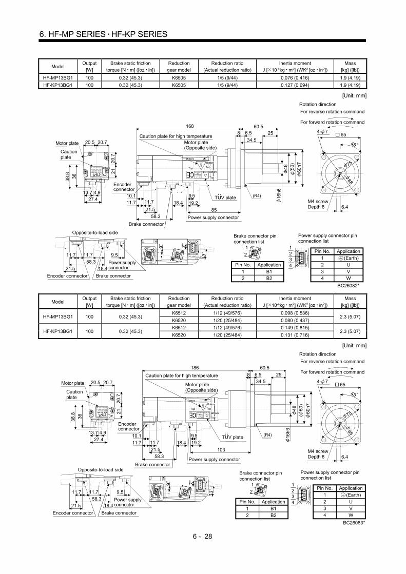
6 - 28
6. HF-MP SERIES HF-KP SERIES
Model Output
[W]
Brake static friction
torque [N m] ([oz in])
Reduction
gear model
Reduction ratio
(Actual reduction ratio)
Inertia moment
J [ 10-4kg m2] (WK2 [oz in2])
Mass
[kg] ([lb])
HF-MP13BG1 100 0.32 (45.3) K6505 1/5 (9/44) 0.076 (0.416) 1.9 (4.19)
HF-KP13BG1 100 0.32 (45.3) K6505 1/5 (9/44) 0.127 (0.694) 1.9 (4.19)
[Unit: mm]
(Earth)
Power supply connector pinconnection list
42
31
1234
ApplicationPin No.
12
34
U
VW
60.5
34.5
25
168
8
18.421.5
11.710.1
8558.3
19.2
6.5
11.79.5 (R4)
BC26082*
2
1
21
Brake connector pin connection list
Brake connector
Encoder connector
TUV plate
Power supply connector
Motor plate(Opposite side)
20.7
21
27.4
20.720.5
3638.8
13.7 4.9
Cautionplate
Motor plate
Top
Bottom
9.5
18.421.558.3
11.711.7
Encoder connector
Power supply connector
Brake connector
Opposite-to-load side
45
4- 7
6.4M4 screwDepth 8
For forward rotation command
For reverse rotation command
Rotation direction
65
88
75
Caution plate for high temperature
Top
Bottom
Top
Bottom
Top
Bottom
16h
64
8
60h
7
(50)
9 7
1321
Pin No.
1
2
Application
B1
B2
Model Output
[W]
Brake static friction
torque [N m] ([oz in])
Reduction
gear model
Reduction ratio
(Actual reduction ratio)
Inertia moment
J [ 10-4kg m2] (WK2 [oz in2])
Mass
[kg] ([lb])
HF-MP13BG1 100 0.32 (45.3) K6512 1/12 (49/576) 0.098 (0.536)
2.3 (5.07) K6520 1/20 (25/484) 0.080 (0.437)
HF-KP13BG1 100 0.32 (45.3) K6512 1/12 (49/576) 0.149 (0.815)
2.3 (5.07) K6520 1/20 (25/484) 0.131 (0.716)
[Unit: mm]
(Earth)
Power supply connector pinconnection list
42
31
1234
ApplicationPin No.
1
2
3
4
U
V
W
60.5
34.5
25
186
8
18.4
21.5
11.7
10.1
10358.3
6.5
19.211.7
9.5 (R4)
BC26083*
2
1
21
Brake connector pin connection list
Brake connector
Encoder connector
TUV plate
Power supply connector
Motor plate(Opposite side)
20.
72
1
27.4
20.720.5
36
38.8
13.7 4.9
Cautionplate
Motor plate
Top
Bottom
9.5
18.421.5
58.3
11.711.7
Encoder connector
Power supply connector
Brake connector
Opposite-to-load side
45
654- 7
88
6.4M4 screwDepth 8
For forward rotation command
For reverse rotation command
Rotation direction
75
16h6
48
60
h7
Caution plate for high temperature
Top
Bottom
Top
Bottom
Top
Bottom (
50)
9 7
1321
Pin No.
1
2
Application
B1
B2
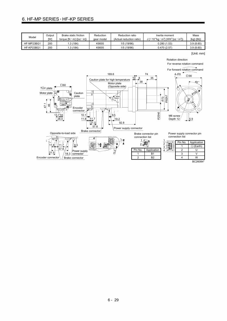
6 - 29
6. HF-MP SERIES HF-KP SERIES
Model Output
[W]
Brake static friction
torque [N m] ([oz in])
Reduction
gear model
Reduction ratio
(Actual reduction ratio)
Inertia moment
J [ 10-4kg m2] (WK2 [oz in2])
Mass
[kg] ([lb])
HF-MP23BG1 200 1.3 (184) K9005 1/5 (19/96) 0.280 (1.53) 3.9 (8.60)
HF-KP23BG1 200 1.3 (184) K9005 1/5 (19/96) 0.470 (2.57) 3.9 (8.60)
[Unit: mm]
(Earth)
Power supply connector pinconnection list
42
31
1234
ApplicationPin No.
1
2
34
U
VW
904- 9
45
114
100
5.9
9
7
13.5
46
28.410
47.1
60
13.7
18.321.557.8
11.8 9.511.7
810
3835
74169.6
21.5
11.8
10.1
92.8
57.8
19.2
9.511.7
25h6
73 82h
7
BC26084*
2
1
21
Brake connector pin connection list
Brake connector
Encoder connector
Power supply connector
Motor plate(Opposite side)
Cautionplate
Motor plate
Power supply connector
Brake connector
Opposite-to-load side
M6 screwDepth 12
Caution plate for high temperature
For forward rotation command
For reverse rotation command
Rotation direction
TUV plate
Top
Bottom
Top
Bottom Top
Bottom
Top
Bottom
Encoder connector
Pin No.
1
2
Application
B1
B2

6 - 30
6. HF-MP SERIES HF-KP SERIES
Model Output
[W]
Brake static friction
torque [N m] ([oz in])
Reduction gear
model
Reduction ratio
(Actual reduction ratio)
Inertia moment
J [ 10-4kg m2] (WK2 [oz in2])
Mass
[kg] ([lb])
HF-MP23BG1 200 1.3 (184) K9012 1/12 (25/288) 0.330 (1.80)
4.5 (9.92) K9020 1/20 (253/5000) 0.300 (1.64)
HF-KP23BG1 200 1.3 (184) K9012 1/12 (25/288) 0.520 (2.84)
4.5 (9.92) K9020 1/20 (253/5000) 0.490 (2.68)
[Unit: mm]
(Earth)
Power supply connector pinconnection list
42
31
1234
ApplicationPin No.
12
34
U
VW
810
3835
74189.6
21.5
11.810.1
112.8
57.8
19.29.5
11.7
904- 9
45
114
100
5.9
9
7
13.5
46
28.4
10
47
.1
60
13.7
25h6
73 82h
7BC26085*
2
1
21
Brake connector pin connection list
Brake connector
Encoder connector
Power supply connector
Motor plate(Opposite side)
Cautionplate
Motor plate
M6 screwDepth 12
Caution plate for high temperature
For forward rotation command
For reverse rotation command
Rotation direction
TUV plate
Top
Bottom
Top
BottomTop
Bottom
TopBottom
18.321.557.8
11.8 9.511.7
Power supply connector
Brake connector
Opposite-to-load side
Encoder connector
Pin No.
1
2
Application
B1
B2
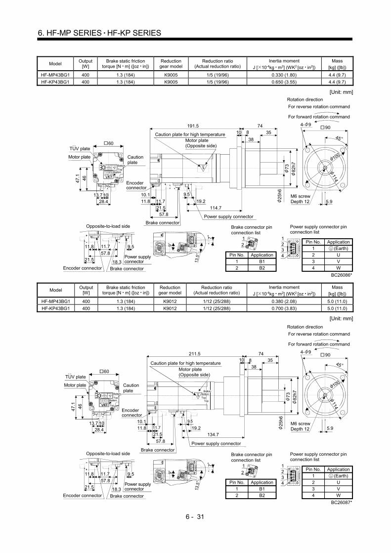
6 - 31
6. HF-MP SERIES HF-KP SERIES
Model Output
[W] Brake static friction
torque [N m] ([oz in]) Reduction gear model
Reduction ratio (Actual reduction ratio)
Inertia moment
J [ 10-4kg m2] (WK2 [oz in2])
Mass
[kg] ([lb])
HF-MP43BG1 400 1.3 (184) K9005 1/5 (19/96) 0.330 (1.80) 4.4 (9.7)
HF-KP43BG1 400 1.3 (184) K9005 1/5 (19/96) 0.650 (3.55) 4.4 (9.7)
[Unit: mm]
(Earth)
Power supply connector pinconnection list
42
31
1234
ApplicationPin No.1
2
34
U
VW
904- 9
114
100
5.9
46
28.410
47.1
60
13.7
18.321.557.8
11.8 9.511.7
25
h6
73
82h
7
BC26086*
21
21
Brake connector pin connection list
Brake connector
Encoder connector
Power supply connector
Motor plate(Opposite side)
Cautionplate
Motor plate
Power supply connector
Brake connector
Opposite-to-load side
M6 screwDepth 12
Caution plate for high temperature
For forward rotation command
For reverse rotation command
Rotation direction
TUV plate
Top
Bottom
Top
Bottom
Encoder connector
9
13.5
7
45810
38
35
74191.5
21.5
11.8
10.1
114.757.8
19.2
9.5
11.7
Pin No.
1
2
Application
B1
B2
Model Output
[W] Brake static friction
torque [N m] ([oz in]) Reduction gear model
Reduction ratio (Actual reduction ratio)
Inertia moment
J [ 10-4kg m2] (WK2 [oz in2])
Mass
[kg] ([lb])
HF-MP43BG1 400 1.3 (184) K9012 1/12 (25/288) 0.380 (2.08) 5.0 (11.0)
HF-KP43BG1 400 1.3 (184) K9012 1/12 (25/288) 0.700 (3.83) 5.0 (11.0)
[Unit: mm]
(Earth)
Power supply connector pinconnection list
42
31
1234
ApplicationPin No.
1
2
3
4
U
V
W18.321.5
57.8
11.8 9.511.7
BC26087*
2
1
21
Brake connector pin connection list
Power supply connector
46
28.4
10
47
.1
60
13.7
Cautionplate
Motor plate
TUV plate
Top
Bottom
Top
Bottom
Brake connector
Opposite-to-load side
Encoder connector
904- 9
114
100
5.9M6 screwDepth 12
For forward rotation command
For reverse rotation command
Rotation direction
45
25h6
73
82h
7
Brake connector
Encoder connector
Power supply connector
Motor plate(Opposite side)
Caution plate for high temperature810
38
3574211.5
21.511.8
10.1
134.7
57.8
19.2
9.5
11.7
TopBottom
Top
Bottom
9
13.5
7
Pin No.
1
2
Application
B1
B2
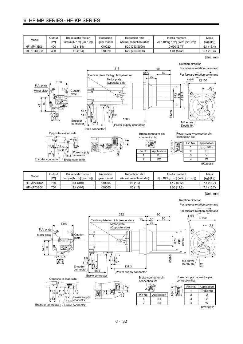
6 - 32
6. HF-MP SERIES HF-KP SERIES
Model Output
[W]
Brake static friction
torque [N m] ([oz in])
Reduction
gear model
Reduction ratio
(Actual reduction ratio)
Inertia moment
J [ 10-4kg m2] (WK2 [oz in2])
Mass
[kg] ([lb])
HF-MP43BG1 400 1.3 (184) K10020 1/20 (253/5000) 0.690 (3.77) 6.1 (13.4)
HF-KP43BG1 400 1.3 (184) K10020 1/20 (253/5000) 1.01 (5.52) 6.1 (13.4)
[Unit: mm]
(Earth)
Power supply connector pinconnection list
42
31
1234
ApplicationPin No.1
2
34
U
VW
18.321.557.8
11.8 9.511.7
BC26088*
2
1
21
Brake connector pin connection list
Power supply connector
46
28.4
10
47.1
60
13.7
Cautionplate
Motor plate
TUV plate
Top
Bottom
Top
Bottom
Brake connector
Opposite-to-load side
Encoder connector
45
100
M8 screwDepth 16
For forward rotation command
For reverse rotation command
Rotation direction
4- 9
32h
6
73
95h
7
Brake connector
Encoder connector Power supply connector
Motor plate(Opposite side)
Caution plate for high temperature1010
39
5090215
21.511.810.1
138.2
57.8
11.7 19.2
9.5
86
TopBottom
Top
Bottom
115
132
9
13.5
7
Pin No.
1
2
Application
B1
B2
Model Output
[W]
Brake static friction
torque [N m] ([oz in])
Reduction
gear model
Reduction ratio
(Actual reduction ratio)
Inertia moment
J [ 10-4kg m2] (WK2 [oz in2])
Mass
[kg] ([lb])
HF-MP73BG1 750 2.4 (340) K10005 1/5 (1/5) 1.12 (6.12) 7.1 (15.7)
HF-KP73BG1 750 2.4 (340) K10005 1/5 (1/5) 2.05 (11.2) 7.1 (15.7)
[Unit: mm]
(Earth)
Power supply connector pinconnection list
42
31
1234
ApplicationPin No.
1
2
3
4
U
V
W
45
7
101039
50
90222
21.411.8
137.3
65.5
9.5
19.211.7
9.9
BC26089*
2
1
21
Brake connector pin connection list
56
27.4
57.1
13.7 11.5
Cautionplate
Motor plate
TUV plate
80
Top
Bottom
Top
Bottom
21.418.4
65.5
11.7 9.511.8
Power supply connector
Brake connector
Opposite-to-load side
Encoder connector
32h
6
95h7
Brake connector
Encoder connector
Power supply connector
Motor plate(Opposite side)
Caution plate for high temperature
TopBottom
Top
Bottom
12
100
M8 screwDepth 16
For forward rotation command
For reverse rotation command
Rotation direction
115
132
4- 9
8673
7
7 Pin No.
1
2
Application
B1
B2

6 - 33
6. HF-MP SERIES HF-KP SERIES
Model Output
[W]
Brake static friction
torque [N m] ([oz in])
Reduction
gear model
Reduction ratio
(Actual reduction ratio)
Inertia moment
J [ 10-4kg m2] (WK2 [oz in2])
Mass
[kg] ([lb])
HF-MP73BG1 750 2.4 (340) K10012 1/12 (6048) 1.79 (8.79) 8.2 (18.1)
HF-KP73BG1 750 2.4 (340) K10012 1/12 (6048) 2.72 (14.9) 8.2 (18.1)
[Unit: mm]
(Earth)
Power supply connector pinconnection list
42
31
1234
ApplicationPin No.
12
34
U
VW
BC26090*
2
1
21
21.4 18.4
65.5
11.7 9.511.8
12
56
27.4
57
.1
13.7 11.5
1010
39
50
90244
21.411.8
159.3
65.5
19.2
9.59.911.7
Brake connector pin connection list
Cautionplate
Motor plate
TUV plate
80
Top
Bottom
Top
Bottom
Power supply connector
Brake connector
Opposite-to-load side
Encoder connector
25
h67
3
95
h7
Brake connector
Encoder connector Power supply
connector
Motor plate(Opposite side)
Caution plate for high temperature
86TopBottom
77
7
100
M8 screwDepth 16
For forward rotation command
For reverse rotation command
Rotation direction
115
132
4- 9
45
Bottom
Top
Pin No.
1
2
Application
B1
B2
Model Output
[W]
Brake static friction
torque [N m] ([oz in])
Reduction
gear model
Reduction ratio
(Actual reduction ratio)
Inertia moment
J [ 10-4kg m2] (WK2 [oz in2])
Mass
[kg] ([lb])
HF-MP73BG1 750 2.4 (340) K12020 1/20 (625/12544) 1.85 (10.1) 11 (24.3)
HF-KP73BG1 750 2.4 (340) K12020 1/20 (625/12544) 2.78 (15.2) 11 (24.3)
[Unit: mm]
BC26091*
21.4 18.4
65.5
9.511..711.8
56
27.4
57.1
13.7 11.5
1215
4560
106257
11.8
172.3
65.5
19.2
9.9
11.721.4
9.5
2
1
21
Brake connector pin connection list
Cautionplate
Motor plate
TUV plate80
Top
Bottom
Top
Bottom
Power supply connector
Brake connectorEncoder connector
40h6
11
5h7
Brake connector
Encoder connector
Power supplyconnector
Motor plate(Opposite side)
Caution plate for high temperature
120
M10 screwDepth 20
For forward rotation command
For reverse rotation command
Rotation direction
4- 14
Opposite-to-load side
7
77
140
162
TopBottom
Top
Bottom
90 10
4
(Earth)
Power supply connector pinconnection list
42
31
1234
ApplicationPin No.
1
23
4
UV
W
Pin No.
1
2
Application
B1
B2

6 - 34
6. HF-MP SERIES HF-KP SERIES
6.8.5 For precision application with flange mounting, flange output type reduction gear (without an
electromagnetic brake)
Model Output
[W] Reduction gear model Reduction ratio
Inertia moment
J [ 10-4kg m2] (WK2 [oz in2])
Mass
[kg] ([lb])
HF-MP053G5 50
HPG-14A-05-F0CBJS-S 1/5 0.087 (0.476) 1.1 (2.43)
HPG-14A-11-F0CBKS-S 1/11 0.079 (0.432)
1.2 (2.64) HPG-14A-21-F0CBKS-S 1/21 0.070 (0.383)
HPG-14A-33-F0CBLS-S 1/33 0.064 (0.35)
HPG-14A-45-F0CBLS-S 1/45 0.064 (0.35)
HF-KP053G5 50
HPG-14A-05-F0CBJS-S 1/5 0.120 (0.656) 1.1 (2.42)
HPG-14A-11-F0CBKS-S 1/11 0.112 (0.612)
1.2 (2.65) HPG-14A-21-F0CBKS-S 1/21 0.103 (0.563)
HPG-14A-33-F0CBLS-S 1/33 0.097 (0.53)
HPG-14A-45-F0CBLS-S 1/45 0.097 (0.53)
[Unit: mm]
(Earth)
Power supply connector pin connection list
42
31
1234
ApplicationPin No.
1
2
34
U
VW BC26092*
27.4
20.720.5
21
13.7
20.7
3637.1
Motor plate
Caution plate
4.9
19.211.7
21.5
Opposite-to-load side
Encoder connector Power supply connector
9.511.7
60
6-M4 screwDepth 7
45
30 7
0
30
4- 5.5
6.4
7
9
11.7 19.2
21.5
14H
7
40
56
h7
21+0.4-0.5
3835
88.5
130.4
Motor plate(Opposite side)
Caution plate for high temperature
Encoder connector
11.7Power supply connector
TUV plate9.510.1
C0.5
21
59
55
.5
Top
Bottom
Top
BottomTop
Bottom
Top
Bottom
For forward rotation command
For reverse rotation command
Rotation direction
( 14H7 effective range)5
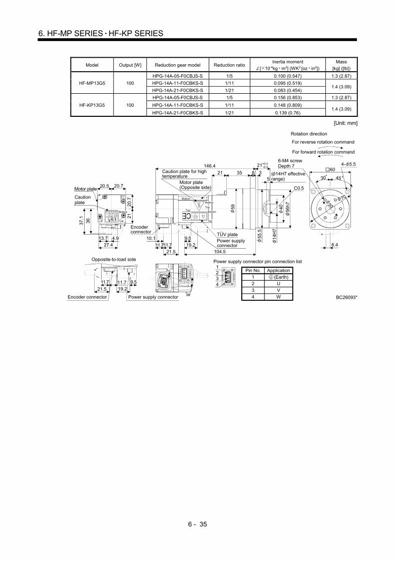
6 - 35
6. HF-MP SERIES HF-KP SERIES
Model Output [W] Reduction gear model Reduction ratio Inertia moment
J [ 10-4kg m2] (WK2 [oz in2])
Mass
[kg] ([lb])
HF-MP13G5 100
HPG-14A-05-F0CBJS-S 1/5 0.100 (0.547) 1.3 (2.87)
HPG-14A-11-F0CBKS-S 1/11 0.095 (0.519) 1.4 (3.09)
HPG-14A-21-F0CBKS-S 1/21 0.083 (0.454)
HF-KP13G5 100
HPG-14A-05-F0CBJS-S 1/5 0.156 (0.853) 1.3 (2.87)
HPG-14A-11-F0CBKS-S 1/11 0.148 (0.809) 1.4 (3.09)
HPG-14A-21-F0CBKS-S 1/21 0.139 (0.76)
[Unit: mm]
(Earth)
Power supply connector pin connection list
42
31
1234
ApplicationPin No.
12
34
U
VW
Top
27.4
20.720.5
21
13.7
20.
7
3637.
1
Motor plate
Caution plate
4.9
21.5
11.719.2
Power supply connectorEncoder connector
Opposite-to-load side
9.511.7
9
760
6-M4 screwDepth 7
45
30 7
0
30
4- 5.5
6.4
BC26093*
19.2
10.1
21.5 104.5
56h
740
14H
7
35 8 3
146.4
TUV plate
Encoder connector
11.711.7
Motor plate(Opposite side)
Caution plate for high temperature
Power supply connector
C0.5
21
55
.5
59
9.5
21+0.4-0.5
Top
Bottom
Top
Bottom
Top
BottomBottom
For forward rotation command
For reverse rotation command
Rotation direction
( 14H7 effective range)5

6 - 36
6. HF-MP SERIES HF-KP SERIES
Model Output
[W] Reduction gear model Reduction ratio
Inertia moment
J [ 10-4kg m2] (WK2 [oz in2])
Mass
[kg] ([lb])
HF-MP13G5 100 HPG-20A-33-F0JMLAS-S 1/33 0.094 (0.514)
2.6 (5.73) HPG-20A-45-F0JMLAS-S 1/45 0.093 (0.508)
HF-KP13G5 100 HPG-20A-33-F0JMLAS-S 1/33 0.150 (0.82)
2.6 (5.73) HPG-20A-45-F0JMLAS-S 1/45 0.149 (0.815)
[Unit: mm]
(Earth)
Power supply connector pin connection list
42
31
1234
ApplicationPin No.
12
34
U
VW
Top
BC26094*
9
7
27.4
20.720.5
21
13.7
20.7
36
37.
1
Motor plateCaution plate
4.9
90
6-M6 screwDepth 10 4- 9
4530
45
105
21.5 19.211.7
Opposite-to-load side
Power supply connectorEncoder connector
11.7 9.5
11.7 19.2
21.5
85h
7
59
24H
7
81026
148.9
107
Encoder connector
Motor plate(Opposite side)
Caution plate for high temperature
Power supply connector
TUV plate9.5
C0.5
27+0.4-0.5
30.5
5
5
89
84
11.7
Top
Bottom
Top
Bottom
Top
BottomBottom
For forward rotation command
For reverse rotation command
Rotation direction
10.1
( 24H7 effective range)
5

6 - 37
6. HF-MP SERIES HF-KP SERIES
Model Output
[W] Reduction gear model Reduction ratio
Inertia moment
J [ 10-4kg m2] (WK2 [oz in2])
Mass
[kg] ([lb])
HF-MP23G5 200 HPG-14A-05-F0AZW-S 1/5 0.289 (1.58) 1.8 (3.97)
HPG-14A-11-F0AZX-S 1/11 0.297 (1.59) 1.9 (4.19)
HF-KP23G5 200 HPG-14A-05-F0AZW-S 1/5 0.441 (2.41) 1.8 (3.97)
HPG-14A-11-F0AZX-S 1/11 0.443 (2.42) 1.9 (4.19)
[Unit: mm]
(Earth)
Power supply connector pin connection list
42
31
1234
ApplicationPin No.
12
34
U
VW
13.7
BC26095*
7
9
60
6-M4 screwDepth 7
5.9
4- 5.5
45
30 7
0
30
21.5
Opposite-to-load side
Encoder connector
19.2 9.5
Power supply connector
11.8
11.7
TUV plate
Motor plate
Caution plate
46
28.4
10
47.
1
60
Motor plate(Opposite side)
Caution plate for high temperature
Encoder connector Power supply
connector
14H
7
40 56h7
11.8
10.1
19.2
21+0.4-0.5
856
140.6
103.3
C0.5
55.5
3
9.511.7
59
60
Top
Bottom
Top
BottomTop
Bottom
Top
Bottom
For forward rotation command
For reverse rotation command
Rotation direction
( 14H7 effective range)5

6 - 38
6. HF-MP SERIES HF-KP SERIES
Model Output
[W] Reduction gear model Reduction ratio
Inertia moment
J [ 10-4kg m2] (WK2 [oz in2])
Mass
[kg] ([lb])
HF-MP23G5 200
HPG-20A-21-F0EKS-S 1/21 0.586 (3.20)
3.4 (7.50) HPG-20A-33-F0ELS-S 1/33 0.540 (2.95)
HPG-20A-45-F0FLS-S 1/45 0.539 (2.95)
HF-KP23G5 200
HPG-20A-21-F0EKS-S 1/21 0.738 (4.04)
3.4 (7.50) HPG-20A-33-F0ELS-S 1/33 0.692 (3.78)
HPG-20A-45-F0FLS-S 1/45 0.691 (3.78)
[Unit: mm]
(Earth)
Power supply connector pin connection list
42
31
1234
ApplicationPin No.
12
34
U
VW
Top
BC26096*
Caution plate
TUV plate
Motor plate
46
28.4
10
47.1
60
7
9
4530
90
6-M6 screwDepth 10 4- 9
45 1
05
13.7
21.5
Opposite-to-load side
Encoder connector
11.8 19.2
11.7
9.5
Power supply connector
Motor plate(Opposite side)
Caution plate for high temperature
Encoder connector
Power supply connector 24
H7
59 85
h7
11.8
10.1
19.2
27+0.4-0.5
1035
147.6
110.3
C0.5
84
826
9.5
11.7
89Bottom
Top
BottomTop
Bottom
Top
Bottom
For forward rotation command
For reverse rotation command
Rotation direction
( 24H7 effective range)5
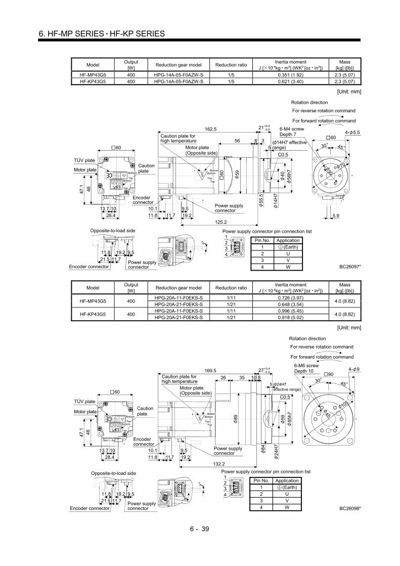
6 - 39
6. HF-MP SERIES HF-KP SERIES
Model
Output [W]
Reduction gear model Reduction ratio Inertia moment
J [ 10-4kg m2] (WK2 [oz in2]) Mass
[kg] ([lb])
HF-MP43G5 400 HPG-14A-05-F0AZW-S 1/5 0.351 (1.92) 2.3 (5.07)
HF-KP43G5 400 HPG-14A-05-F0AZW-S 1/5 0.621 (3.40) 2.3 (5.07)
[Unit: mm]
(Earth)
Power supply connector pin connection list
42
31
1234
ApplicationPin No.1
2
34
U
VW BC26097*
7
9
60
6-M4 screwDepth 7
45
5.9
30 7
0
30
4- 5.5
21.5
Encoder connector
9.5
Power supply connector
19.211.8
11.7
Caution plate
46
28.4
10
47.1
60
13.7
Motor plate(Opposite side)
Caution plate for high temperature
Encoder connector
Power supply connector
14H
7
40
56h7
11.8
10.1
19.2
21+0.4-0.5
856
162.5
125.2
C0.5
55.5
6
0
5
9
3
11.79.5
Top
Bottom
Top
BottomTop
Bottom
Top
Bottom
For forward rotation command
For reverse rotation command
Rotation direction
TUV plate
Motor plate
Opposite-to-load side
( 14H7 effective range)5
Model Output
[W] Reduction gear model Reduction ratio
Inertia moment J [ 10-4kg m2] (WK2 [oz in2])
Mass [kg] ([lb])
HF-MP43G5 400 HPG-20A-11-F0EKS-S 1/11 0.726 (3.97)
4.0 (8.82) HPG-20A-21-F0EKS-S 1/21 0.648 (3.54)
HF-KP43G5 400 HPG-20A-11-F0EKS-S 1/11 0.996 (5.45)
4.0 (8.82) HPG-20A-21-F0EKS-S 1/21 0.918 (5.02)
[Unit: mm]
(Earth)
Power supply connector pin connection list
42
31
1234
ApplicationPin No.
1
23
4
UV
W BC26098*
7
9
90
6-M6 screwDepth 10
4530
4- 9
45 1
05Caution plate
46
28.4
10
47.1
60
13.7
21.5
Encoder connector
11.8
11.7
19.2 9.5
Power supply connector
Motor plate(Opposite side)
Caution plate for high temperature
Encoder connector
Power supply connector 2
4H
759 85
h7
11.8
10.1
19.2
27+0.4-0.5
1035
169.5
132.2
C0.5
84
8
8
9
9.5
26
11.7
Top
Bottom
Top
BottomTop
Bottom
Top
Bottom
For forward rotation command
For reverse rotation command
Rotation direction
TUV plate
Motor plate
Opposite-to-load side
( 24H7 effective range)
5

6 - 40
6. HF-MP SERIES HF-KP SERIES
Model Output
[W] Reduction gear model Reduction ratio
Inertia moment
J [ 10-4kg m2] (WK2 [oz in2])
Mass
[kg] ([lb])
HF-MP43G5 400 HPG-32A-33-F0RLAS-S 1/33 0.700 (3.83)
6.1 (13.4) HPG-32A-45-F0RLAS-S 1/45 0.694 (3.79)
HF-KP43G5 400 HPG-32A-33-F0RLAS-S 1/33 0.970 (5.30)
6.1 (13.4) HPG-32A-45-F0RLAS-S 1/45 0.964 (5.27)
[Unit: mm]
(Earth)
Power supply connector pin connection list
42
31
1234
ApplicationPin No.
12
34
U
VW BC26099*
7
9
120
6-M8 screwDepth 12
4530
4- 11
60 1
35Caution plate
46
28.4
10
47.
1
60
13.7
9.5
21.5 11.7
Encoder connector Power supply connector
11.8 19.2
Motor plate(Opposite side)
Caution plate for high temperature
Encoder connector
Power supply connector
32H
78
411
5h7
11.8
10.119.2
35+0.4-0.5
1341
181.5
144.2
C0.5
1
18
9.5
29
8
4
11
4
11.7
13
TopBottom
Top
BottomTop
Bottom
Top
Bottom
For forward rotation command
For reverse rotation command
Rotation direction
TUV plate
Motor plate
Opposite-to-load side
( 32H7 effective range)5

6 - 41
6. HF-MP SERIES HF-KP SERIES
Model Output
[W] Reduction gear model Reduction ratio
Inertia moment
J [ 10-4kg m2] (WK2 [oz in2])
Mass
[kg] ([lb])
HF-MP73G5 750 HPG-20A-05-F0FEOS-S 1/5 1.25 (6.84) 4.9 (10.8)
HPG-20A-11-F0FEPS-S 1/11 1.16 (6.34) 5.2 (11.5)
HF-KP73G5 750 HPG-20A-05-F0FEOS-S 1/5 2.08 (11.4) 4.9 (10.8)
HPG-20A-11-F0FEPS-S 1/11 1.99 (10.9) 5.2 (11.5)
[Unit: mm]
(Earth)
Power supply connector pin connection list
42
31
1234
ApplicationPin No.
12
34
U
VW BC26100*
7
7
90
6-M6 screwDepth 10
4530
4- 9
45
105
12
9.521.4
19.2
Encoder connectorPower supply connector
11.8
11.7
Caution plate
56
27.4
57.
1
80
11.513.7
Motor plate(Opposite side)
Caution plate for high temperature
Encoder connector
Power supply connector
24H
7
59 85h
7
11.8
9.9
19.2
27+0.4-0.5
1026
191.8
150.3
C0.5
30
84
8
89
80
21.4
9.511.7
12
Top
Bottom
Top
Bottom
Top
Bottom
Top
Bottom
For forward rotation command
For reverse rotation command
Rotation direction
TUV plate
Motor plate
Opposite-to-load side
( 24H7 effective range)5
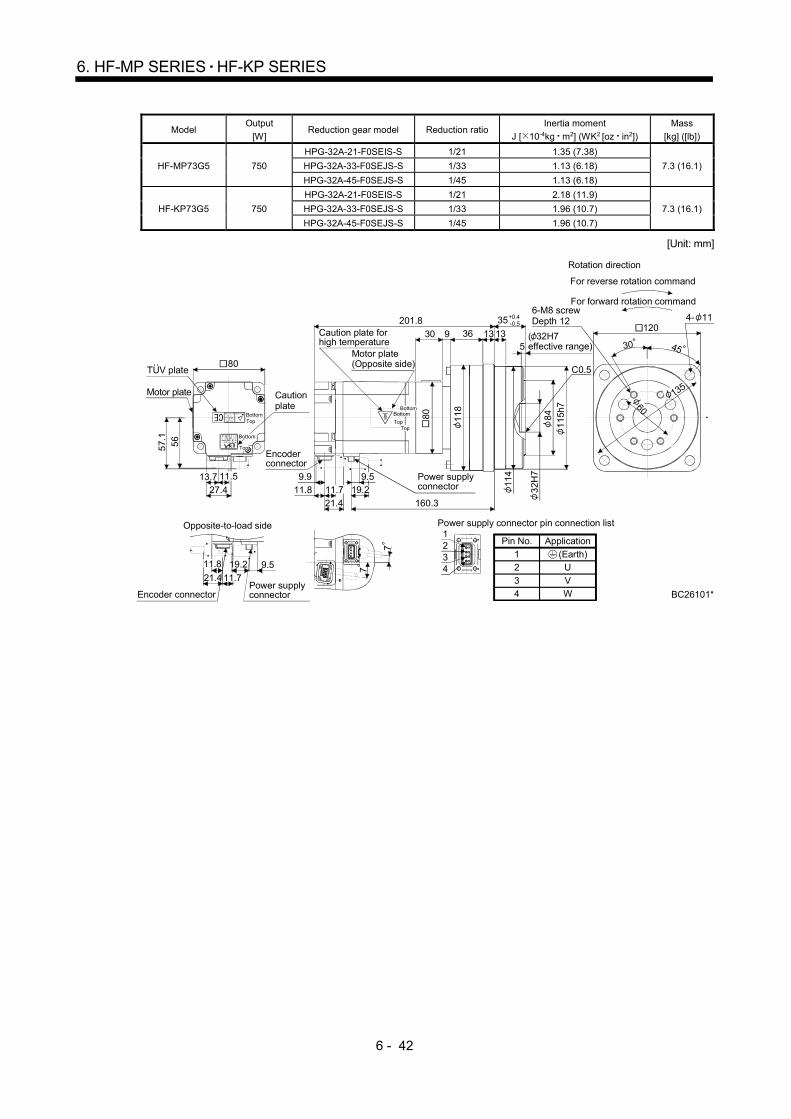
6 - 42
6. HF-MP SERIES HF-KP SERIES
Model Output
[W] Reduction gear model Reduction ratio
Inertia moment
J [ 10-4kg m2] (WK2 [oz in2])
Mass
[kg] ([lb])
HF-MP73G5 750
HPG-32A-21-F0SEIS-S 1/21 1.35 (7.38)
7.3 (16.1) HPG-32A-33-F0SEJS-S 1/33 1.13 (6.18)
HPG-32A-45-F0SEJS-S 1/45 1.13 (6.18)
HF-KP73G5 750
HPG-32A-21-F0SEIS-S 1/21 2.18 (11.9)
7.3 (16.1) HPG-32A-33-F0SEJS-S 1/33 1.96 (10.7)
HPG-32A-45-F0SEJS-S 1/45 1.96 (10.7)
[Unit: mm]
(Earth)
Power supply connector pin connection list
42
31
1234
ApplicationPin No.
12
34
U
VW BC26101*
7
7
120
6-M8 screwDepth 12
4530
4- 11
60
135
9.521.4
Encoder connector
11.8
11.7
Caution plate
56
27.4
57.
1
80
13.7 11.5
Motor plate(Opposite side)
Caution plate for high temperature
Encoder connector
Power supply connector 3
2H
7
84
11
5h7
11.8
9.9
35+0.4-0.5
1336201.8
160.3
C0.5
30
114
21.4
9
11.79.5
8
0
1
18
13
TopBottom
Top
Bottom
Top
Bottom
Top
Bottom
For forward rotation command
For reverse rotation command
Rotation direction
TUV plate
Motor plate
Opposite-to-load side
19.2
Power supply connector
19.2
( 32H7 effective range)5
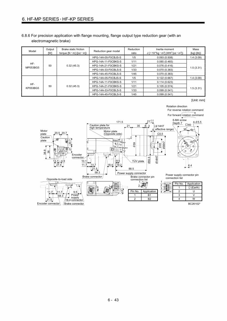
6 - 43
6. HF-MP SERIES HF-KP SERIES
6.8.6 For precision application with flange mounting, flange output type reduction gear (with an
electromagnetic brake)
Model Output
[W]
Brake static friction
torque [N m] ([oz in]) Reduction gear model
Reduction
ratio
Inertia moment
J [ 10-4kg m2] (WK2 [oz in2])
Mass
[kg] ([lb])
HF-
MP053BG5 50 0.32 (45.3)
HPG-14A-05-F0CBJS-S 1/5 0.093 (0.508) 1.4 (3.09)
HPG-14A-11-F0CBKS-S 1/11 0.085 (0.465)
1.5 (3.31) HPG-14A-21-F0CBKS-S 1/21 0.076 (0.416)
HPG-14A-33-F0CBLS-S 1/33 0.070 (0.383)
HPG-14A-45-F0CBLS-S 1/45 0.070 (0.383)
HF-
KP053BG5 50 0.32 (45.3)
HPG-14A-05-F0CBJS-S 1/5 0.122 (0.667) 1.4 (3.09)
HPG-14A-11-F0CBKS-S 1/11 0.114 (0.623)
1.5 (3.31) HPG-14A-21-F0CBKS-S 1/21 0.105 (0.574)
HPG-14A-33-F0CBLS-S 1/33 0.099 (0.541)
HPG-14A-45-F0CBLS-S 1/45 0.099 (0.541)
[Unit: mm]
(Earth)
Power supply connector pinconnection list
42
31
1234
ApplicationPin No.
1
2
34
U
VW
Pin No.
1
2
Application
B1
B2
Brake connector pin connection list
2
1
21
9 7
132
1
9.5
21.5
Opposite-to-load side
Power supply connector
Encoder connector18.4
58.3
Brake connector
11.711.7
60
6-M4 screwDepth 7
Rotation direction
4530
4- 5.5
30
70
6.4
20.7
21
27.4
20.720.5
3638.
8
Motor plateCaution plate
4.913.7
Top
Bottom
Motor plate(Opposite side)
Caution plate for high temperature
3521 3
171.5
Brake connector
8
18.4
21.5
11.7
10.1
88.5
Power supply connector
TUV plate 14H
74
0
56
h7
58.3
19.2
11.7
9.5
21 0.40.5
C0.5
55.5
59
Encoder connector
( 14H7 effective range)
Top
Bottom
TopBottom
BC26102*
For forward rotation command
For reverse rotation command
Bottom
Top
5
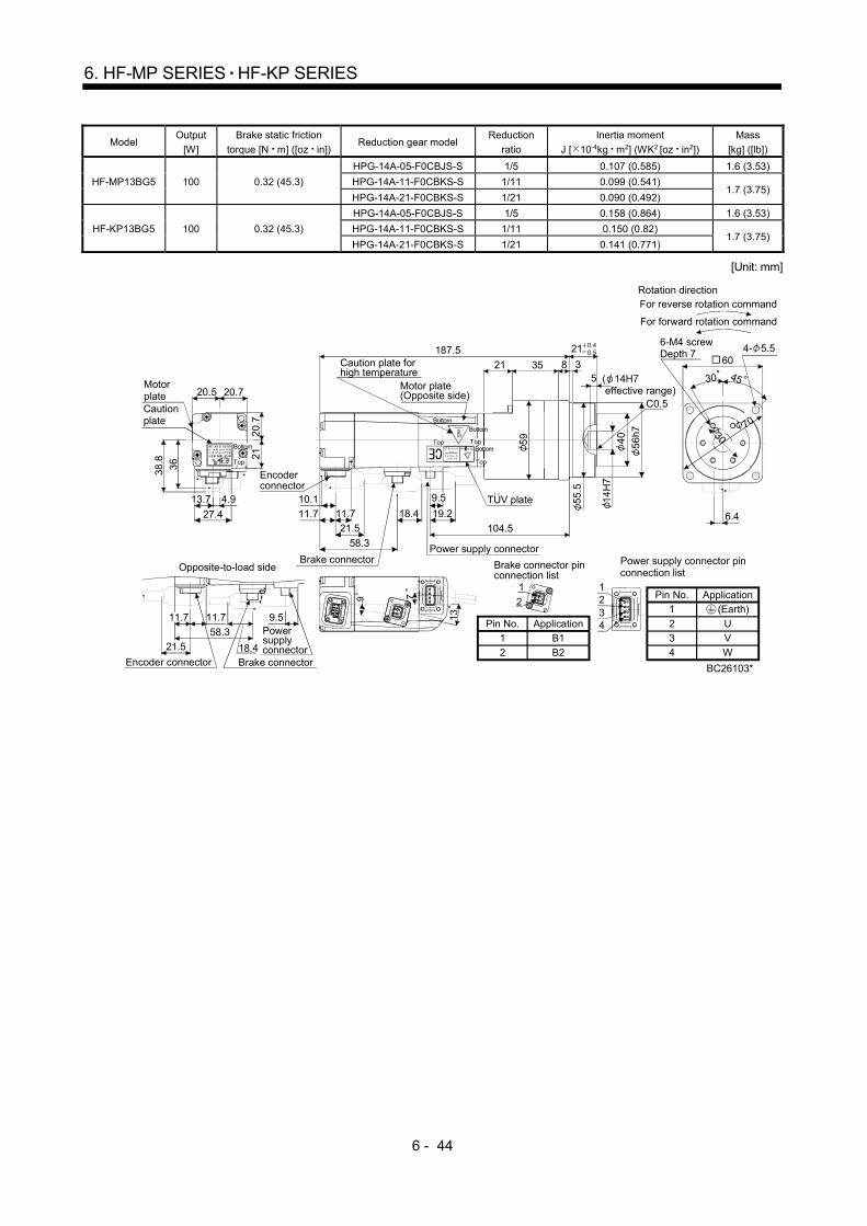
6 - 44
6. HF-MP SERIES HF-KP SERIES
Model Output
[W]
Brake static friction
torque [N m] ([oz in]) Reduction gear model
Reduction
ratio
Inertia moment
J [ 10-4kg m2] (WK2 [oz in2])
Mass
[kg] ([lb])
HF-MP13BG5 100 0.32 (45.3)
HPG-14A-05-F0CBJS-S 1/5 0.107 (0.585) 1.6 (3.53)
HPG-14A-11-F0CBKS-S 1/11 0.099 (0.541) 1.7 (3.75)
HPG-14A-21-F0CBKS-S 1/21 0.090 (0.492)
HF-KP13BG5 100 0.32 (45.3)
HPG-14A-05-F0CBJS-S 1/5 0.158 (0.864) 1.6 (3.53)
HPG-14A-11-F0CBKS-S 1/11 0.150 (0.82) 1.7 (3.75)
HPG-14A-21-F0CBKS-S 1/21 0.141 (0.771)
[Unit: mm]
Pin No.
1
2
Application
B1
B2
(Earth)
Power supply connector pinconnection list
42
31
1234
ApplicationPin No.1
23
4
UV
W
2
1
21
9 7
13
21
9.5
18.421.5
58.3
11.711.7
20.
721
27.4
20.720.5
36
38.8
4.913.7
3521 3187.5
8
18.4
21.511.7
10.1
104.5
14
H7
40
56
h7
58.3
19.2
C0.5
55
.5
9.5
11.75
9
Motor plateCaution plate
Top
Bottom
Encoder connector
Top
Bottom
Opposite-to-load side
Power supply connector
Encoder connector Brake connector
Brake connectorPower supply connector
Brake connector pin connection list
BC26103*
30
70
6.4
4530
604- 5.5
Rotation direction
For forward rotation command
For reverse rotation command
6-M4 screwDepth 7
Caution plate for high temperature
Motor plate(Opposite side)
Top
Bottom
Top
Bottom
21 0.40.5
( 14H7 effective range)
5
TUV plate
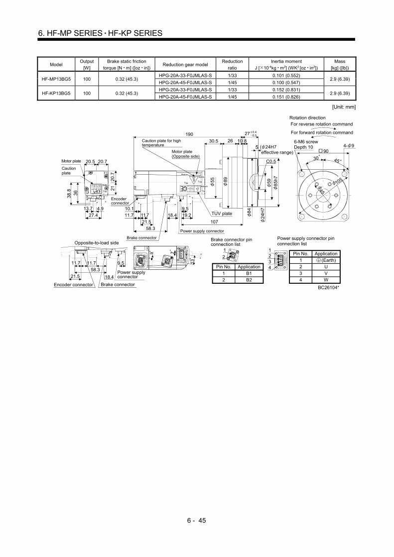
6 - 45
6. HF-MP SERIES HF-KP SERIES
Model Output
[W]
Brake static friction
torque [N m] ([oz in]) Reduction gear model
Reduction
ratio
Inertia moment
J [ 10-4kg m2] (WK2 [oz in2])
Mass
[kg] ([lb])
HF-MP13BG5 100 0.32 (45.3) HPG-20A-33-F0JMLAS-S 1/33 0.101 (0.552)
2.9 (6.39) HPG-20A-45-F0JMLAS-S 1/45 0.100 (0.547)
HF-KP13BG5 100 0.32 (45.3) HPG-20A-33-F0JMLAS-S 1/33 0.152 (0.831)
2.9 (6.39) HPG-20A-45-F0JMLAS-S 1/45 0.151 (0.826)
[Unit: mm]
(Earth)
Power supply connector pinconnection list
42
31
1234
ApplicationPin No.
12
34
U
VW
Pin No.
1
2
Application
B1
B2
BC26104*
9 7
1321
18.421.5
58.3
11.7 9.511.7
Brake connector
Power supply connector
20.7
21
27.4
20.720.5
36
38.8
4.913.7
Top
Bottom
2630.5
190
10
18.4
21.5
11.7
10.1
107
24H
759 85
h7
58.3
19.2
C0.5
84
8
9.511.7
Cautionplate
Motor plate
Encoder connector
Caution plate for high temperature
Motor plate(Opposite side)
Brake connector
Power supply connector
Top
Bottom
Top
Bottom
Top
Bottom
55 89
27 0.40.5
45
105
6-M6 screwDepth 10
Rotation direction
For forward rotation command
For reverse rotation command
90
4530
4- 9
Brake connector pin connection list
2
1
21
Opposite-to-load side
Encoder connector
( 24H7 effective range)
5
TUV plate

6 - 46
6. HF-MP SERIES HF-KP SERIES
Model Output
[W]
Brake static friction
torque [N m] ([oz in]) Reduction gear model
Reduction
ratio
Inertia moment
J [ 10-4kg m2] (WK2 [oz in2])
Mass
[kg] ([lb])
HF-MP23BG5 200 1.3 (184) HPG-14A-05-F0AZW-S 1/5 0.321 (1.76) 2.4 (5.29)
HPG-14A-11-F0AZX-S 1/11 0.323 (1.77) 2.5 (5.51)
HF-KP23BG5 200 1.3 (184) HPG-14A-05-F0AZW-S 1/5 0.511 (2.79) 2.4 (5.29)
HPG-14A-11-F0AZX-S 1/11 0.513 (2.81) 2.5 (5.51)
[Unit: mm]
(Earth)
Power supply connector pinconnection list
42
31
1234
ApplicationPin No.
12
3
4
U
V
W
Pin No.
1
2
Application
B1
B2
BC26105*
2
1
21
9
7
13.5
5.9
70
30
21.5
57.8
11.7 9.511.8
18.3
46
28.4
10
47.1
13.7
56
180.1
8
C0.5
60
3
21.511.8
10.1
103.3
57.8
19.2
9.5
11.7
14H
7
55.5
Motor plate
60
Top
Bottom
Top
Bottom
Caution plate
Encoder connector
Caution plate for high temperature
Motor plate (Opposite side)
Top
Bottom
Top
Bottom
Brake connectorPower supply connector
59 40 56
h7
21 0.40.5
6-M4 screwDepth 7 4- 5.5
60
4530
Rotation direction
For forward rotation command
For reverse rotation command
Brake connector pin connection listOpposite-to-load side
Encoder connector Brake connector
Power supply connector
( 14H7 effective range)
5
TUV plate

6 - 47
6. HF-MP SERIES HF-KP SERIES
Model Output
[W]
Brake static friction
torque [N m] ([oz in]) Reduction gear model
Reduction
ratio
Inertia moment
J [ 10-4kg m2] (WK2 [oz in2])
Mass
[kg] ([lb])
HF-MP23BG5 200 1.3 (184)
HPG-20A-21-F0EKS-S 1/21 0.618 (3.38)
4.1 (9.04) HPG-20A-33-F0ELS-S 1/33 0.572 (3.18)
HPG-20A-45-F0ELS-S 1/45 0.571 (3.12)
HF-KP23BG5 200 1.3 (184)
HPG-20A-21-F0EKS-S 1/21 0.808 (4.42)
4.1 (9.04) HPG-20A-33-F0ELS-S 1/33 0.762 (4.17)
HPG-20A-45-F0ELS-S 1/45 0.761 (4.16)
[Unit: mm]
(Earth)
Power supply connector pinconnection list
42
31
1234
ApplicationPin No.1
23
4
UV
W
Pin No.
1
2
Application
B1
B2
2
1
21
21.5
57.8
11.7 9.511.8
18.3
46
28.4
10
47.
1
13.7
35
187.1
8
24H
7
C0.5
10
21.5
11.8
10.1
110.3
Power supply connector57.8
19.2
849.5
11.7
26
Motor plate
60
Caution plate
Top
Bottom
Top
Bottom
Encoder connector
Brake connector
Caution plate for high temperature
Motor plate (Opposite side)
Top
Bottom
Top
Bottom
89 5985
h7 105
45
6-M6 screwDepth 10
Rotation direction
For forward rotation command
For reverse rotation command
4- 990
4530
BC26106*
Brake connector pin connection list
7
13.59
Opposite-to-load side
Encoder connector Brake connector
Power supply connector
27 0.40.5
( 24H7 effective range)
5
TUV plate

6 - 48
6. HF-MP SERIES HF-KP SERIES
Model Output
[W]
Brake static friction
torque [N m] ([oz in]) Reduction gear model
Reduction
ratio
Inertia moment
J [ 10-4kg m2] (WK2 [oz in2])
Mass
[kg] ([lb])
HF-MP43BG5 400 1.3 (184) HPG-14A-05-F0AZSW-S 1/5 0.381 (2.08) 2.9 (6.39)
HF-KP43BG5 400 1.3 (184) HPG-14A-05-F0AZSW-S 1/5 0.701 (3.83) 2.9 (6.39)
[Unit: mm]
BC26107*
2
1
21
7
13.5
21.5
57.8
11.7 9.511.8
18.3
Opposite-to-load side
46
28.4
10
47.1
13.7
Motor plate
60
Caution plate
Top
Bottom
Top
Bottom
TUV plate
202
3
14H
7
40 56
h7
C0.5
8
21.5
11.810.1
125.2
57.8
19.2
56
9.511.7
55.5
60Encoder
connector
Caution plate for high temperature
Brake connectorPower supply connector
Top
Bottom
Top
Bottom
Motor plate (Opposite side)
59
21 0.40.5
6-M4 screwDepth 7
Brake connector pin connection list
9
Encoder connector Brake connector
Power supply connector
30
70
5.9
Rotation direction
For forward rotation command
For reverse rotation command
4- 5.560
4530( 14H7 effective range)
5
(Earth)
Power supply connector pinconnection list
42
31
1234
ApplicationPin No.
12
34
U
VW
Pin No.
1
2
Application
B1
B2

6 - 49
6. HF-MP SERIES HF-KP SERIES
Model Output
[W]
Brake static friction
torque [N m] ([oz in]) Reduction gear model
Reduction
ratio
Inertia moment
J [ 10-4kg m2] (WK2 [oz in2])
Mass
[kg] ([lb])
HF-MP43BG5 400 1.3 (184) HPG-20A-11-F0EKS-S 1/11 0.756 (4.13)
4.6 (10.1) HPG-20A-21-F0EKS-S 1/21 0.678 (3.71)
HF-KP43BG5 400 1.3 (184) HPG-20A-11-F0EKS-S 1/11 1.08 (5.91)
4.6 (10.1) HPG-20A-21-F0EKS-S 1/21 0.998 (5.46)
[Unit: mm]
(Earth)
Power supply connector pinconnection list
42
31
1234
ApplicationPin No.
12
34
U
VW
Pin No.
1
2
Application
B1
B2
BC26108*
2
1
21
9
7
13.5
21.5
57.8
Brake connector
11.7 9.511.8
18.3
Opposite-to-load side
Power supply connector
46
28.4
10
47.
1
13.7
35
209
8
24H
759 85
h7
C0.5
10
21.5
11.8
10.1
132.2
57.8
19.2
84
26
9.5
11.7
89
Motor plate
60
Caution plate
Top
Bottom
Top
Bottom
Caution plate for high temperature
Motor plate (Opposite side)
Encoder connector
Brake connector
Power supply connector
Top
Bottom
Top
Bottom
27 0.40.5
45
105
Rotation direction
For forward rotation command
For reverse rotation command
6-M6 screwDepth 10 4- 9
90
30 45
Brake connector pin connection list
Encoder connector
( 24H7 effective range)
5
TUV plate

6 - 50
6. HF-MP SERIES HF-KP SERIES
Model Output
[W]
Brake static friction
torque [N m] ([oz in]) Reduction gear model
Reduction
ratio
Inertia moment
J [ 10-4kg m2] (WK2 [oz in2])
Mass
[kg] ([lb])
HF-MP43BG5 400 1.3 (184) HPG-32A-33-F0RLAS-S 1/33 0.730 (3.99)
6.7 (14.8) HPG-32A-45-F0RLAS-S 1/45 0.724 (3.94)
HF-KP43BG5 400 1.3 (184) HPG-32A-33-F0RLAS-S 1/33 1.05 (5.74)
6.7 (14.8) HPG-32A-45-F0RLAS-S 1/45 1.04 (5.69)
[Unit: mm]
BC26109*
2
1
21
9
7
13.5
21.5
57.89.511.8
18.3
11.7
46
28.410
47.
1
13.7
Caution plate for high temperature
Motor plate (Opposite side)
41
221
32H
7
8411
5h7
C0.5
13
21.511.8
10.1
144.2
57.8
29
11
4
118
9.519.211.7
84
13
Brake connector
Power supply connector
Top
Bottom
TopBottom
35 0.40.5
Motor plate
60
Caution plate
Top
Bottom
Top
Bottom
Encoder connector
60
135
Rotation direction
For forward rotation command
For reverse rotation command
6-M8 screwDepth 12
1204- 11
4530
Brake connector pin connection listOpposite-to-load side
Encoder connector Brake connector
Power supply connector
( 32H7 effective range)
5
TUV plate
(Earth)
Power supply connector pinconnection list
42
31
1234
ApplicationPin No.
12
3
4
U
V
W
Pin No.
1
2
Application
B1
B2
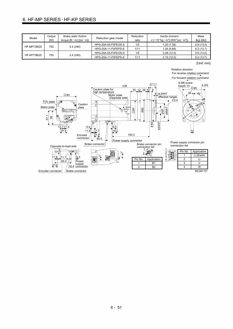
6 - 51
6. HF-MP SERIES HF-KP SERIES
Model Output
[W]
Brake static friction
torque [N m] ([oz in]) Reduction gear model
Reduction
ratio
Inertia moment
J [ 10-4kg m2] (WK2 [oz in2])
Mass
[kg] ([lb])
HF-MP73BG5 750 2.4 (340) HPG-20A-05-F0FEOS-S 1/5 1.35 (7.38) 5.9 (13.0)
HPG-20A-11-F0FEPS-S 1/11 1.26 (6.89) 6.2 (13.7)
HF-KP73BG5 750 2.4 (340) HPG-20A-05-F0FEOS-S 1/5 2.28 (12.5) 5.9 (13.0)
HPG-20A-11-F0FEPS-S 1/11 2.19 (12.0) 6.2 (13.7)
[Unit: mm]
2
1
21
21.4
Encoder connector
65.5
11.7 9.511.8
18.4
7
7
7
45
105
12
45
56
27.4
57.
1
11.513.7
26
235
8
24H
759 85
h7
C0.5
10
21.411.89.9
150.3
65.5
30
84
80
9.511.7 19.2
12
89
Encoder connector
Motor plate
80
Caution plate
TopBottom
Top
Bottom
Brake connectorPower supply connector
Caution plate for high temperature
Motor plate (Opposite side)
27 0.40.5
Top
Bottom
TopBottom
Rotation direction
For forward rotation command
For reverse rotation command
6-M6 screwDepth 10
904- 9
30
BC26110*
Brake connector pin connection list
Power supply connector
Brake connector
Opposite-to-load side
5
TUV plate
( 24H7 effective range)
(Earth)
Power supply connector pinconnection list
42
31
1234
ApplicationPin No.1
2
34
U
VW
Pin No.
1
2
Application
B1
B2

6 - 52
6. HF-MP SERIES HF-KP SERIES
Model Output
[W]
Brake static friction
torque [N m] ([oz in]) Reduction gear model
Reduction
ratio
Inertia moment
J [ 10-4kg m2] (WK2 [oz in2])
Mass
[kg] ([lb])
HF-MP73BG5 750 2.4 (340)
HPG-32A-21-F0SEIS-S 1/21 1.45 (7.93)
8.3 (18.3) HPG-32A-33-F0SEJS-S 1/33 1.23 (6.73)
HPG-32A-45-F0SEJS-S 1/45 1.23 (6.73)
HF-KP73BG5 750 2.4 (340)
HPG-32A-21-F0SEIS-S 1/21 2.38 (13.0)
8.3 (18.3) HPG-32A-33-F0SEJS-S 1/33 2.16 (11.8)
HPG-32A-45-F0SEJS-S 1/45 2.16 (11.8)
[Unit: mm]
(Earth)
Power supply connector pinconnection list
42
31
1234
ApplicationPin No.
12
3
4
U
V
W
Pin No.
1
2
Application
B1
B2
BC26111*
2
1
21
77
7
65.5
18.4
11.7 9.5
21.4
11.8
56
27.4
57.
1
11.513.7
36
245
32H
7
84
C0.5
13
11.8
9.9
160.3Encoder connector 65.5
30
114
13
9.5
19.2
21.4
11.71
18
9
Power supply connector
Top
Bottom
TopBottom
Caution plate for high temperature
Motor plate (Opposite side)
80
115h
7Motor plate
80
Caution plate
TopBottom
Top
Bottom
35 0.40.5
60
135
Rotation direction
For forward rotation command
For reverse rotation command
6-M8 screwDepth 12 4- 11
120
30 45
Brake connector pin connection list
Brake connectorOpposite-to-load side
Power supply connector
Brake connectorEncoder connector
( 32H7 effective range)
5
TUV plate
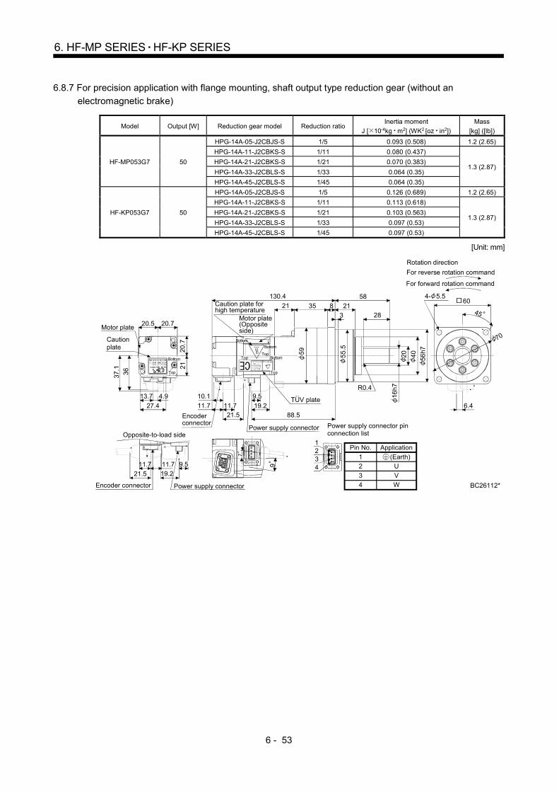
6 - 53
6. HF-MP SERIES HF-KP SERIES
6.8.7 For precision application with flange mounting, shaft output type reduction gear (without an
electromagnetic brake)
Model Output [W] Reduction gear model Reduction ratio Inertia moment
J [ 10-4kg m2] (WK2 [oz in2])
Mass
[kg] ([lb])
HF-MP053G7 50
HPG-14A-05-J2CBJS-S 1/5 0.093 (0.508) 1.2 (2.65)
HPG-14A-11-J2CBKS-S 1/11 0.080 (0.437)
1.3 (2.87) HPG-14A-21-J2CBKS-S 1/21 0.070 (0.383)
HPG-14A-33-J2CBLS-S 1/33 0.064 (0.35)
HPG-14A-45-J2CBLS-S 1/45 0.064 (0.35)
HF-KP053G7 50
HPG-14A-05-J2CBJS-S 1/5 0.126 (0.689) 1.2 (2.65)
HPG-14A-11-J2CBKS-S 1/11 0.113 (0.618)
1.3 (2.87) HPG-14A-21-J2CBKS-S 1/21 0.103 (0.563)
HPG-14A-33-J2CBLS-S 1/33 0.097 (0.53)
HPG-14A-45-J2CBLS-S 1/45 0.097 (0.53)
[Unit: mm]
BC26112*
7
9
19.211.7 11.7
21.5
9.5
20.7
21
27.4
20.720.5
13.7
3637.1
4.9
70
6.4
16h
7
40 56h7
11.7 19.2
10.1
21.5
21
58
3
821
28
130.4
88.5
9.5
11.7
55
.5
59
20
R0.4
35
Encoder connector
Power supply connector
Bottom
Motor plate
Caution plate
Top
Bottom
Caution plate for high temperature
Motor plate(Opposite side)
Bottom
TopTop
Bottom
Top
Rotation direction
For forward rotation command
For reverse rotation command
4- 5.5
45
60
Opposite-to-load side
Encoder connector Power supply connector
TUV plate
(Earth)
Power supply connector pinconnection list
42
31
1234
ApplicationPin No.
1
2
3
4
U
V
W
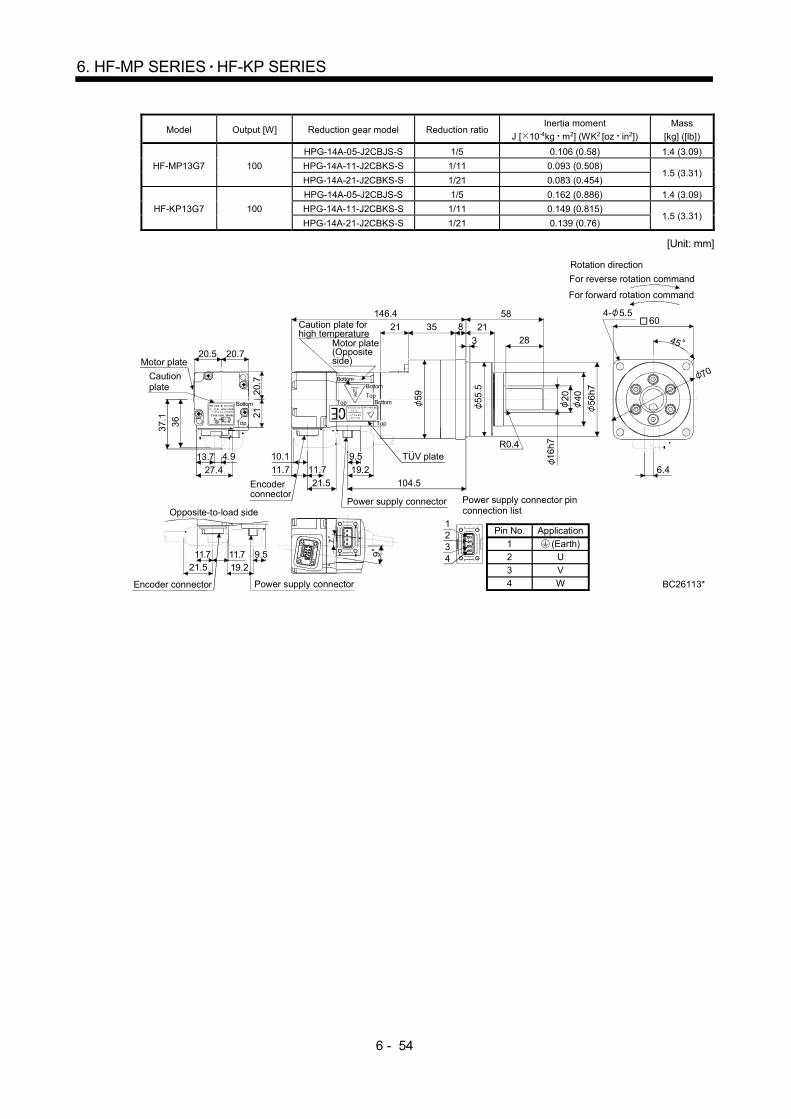
6 - 54
6. HF-MP SERIES HF-KP SERIES
Model Output [W] Reduction gear model Reduction ratio Inertia moment
J [ 10-4kg m2] (WK2 [oz in2])
Mass
[kg] ([lb])
HF-MP13G7 100
HPG-14A-05-J2CBJS-S 1/5 0.106 (0.58) 1.4 (3.09)
HPG-14A-11-J2CBKS-S 1/11 0.093 (0.508) 1.5 (3.31)
HPG-14A-21-J2CBKS-S 1/21 0.083 (0.454)
HF-KP13G7 100
HPG-14A-05-J2CBJS-S 1/5 0.162 (0.886) 1.4 (3.09)
HPG-14A-11-J2CBKS-S 1/11 0.149 (0.815) 1.5 (3.31)
HPG-14A-21-J2CBKS-S 1/21 0.139 (0.76)
[Unit: mm]
BC26113*
7
9
19.211.7
21.59.511.7
20.
72
1
27.4
20.720.5
13.7
36
37.
1
4.9
70
6.4
16h
7
40 56h7
11.7 19.2
10.1
21.5
21
58
3
821
28
146.4
104.5
20
35
11.7
9.5
59 55
.5
R0.4
Bottom
Bottom
Bottom
TopTop
Top
Motor plate
Caution plate
Top
Bottom
Encoder connector
Power supply connector
Caution plate for high temperature
Motor plate(Opposite side)
Rotation direction
For forward rotation command
For reverse rotation command
4- 5.560
45
Power supply connectorEncoder connector
Opposite-to-load side
TUV plate
(Earth)
Power supply connector pinconnection list
42
31
1234
ApplicationPin No.
12
34
U
VW

6 - 55
6. HF-MP SERIES HF-KP SERIES
Model Output [W] Reduction gear model Reduction ratio Inertia moment
J [ 10-4kg m2] (WK2 [oz in2])
Mass
[kg] ([lb])
HF-MP13G7 100 HPG-20A-33-J2JMLAS-S 1/33 0.095 (0.519)
3.0 (6.61) HPG-20A-45-J2JMLAS-S 1/45 0.093 (0.508)
HF-KP13G7 100 HPG-20A-33-J2JMLAS-S 1/33 0.151 (0.826)
3.0 (6.61) HPG-20A-45-J2JMLAS-S 1/45 0.149 (0.815)
[Unit: mm]
BC26114*
7
9105
19.221.5
9.511.711.7
20.7
21
27.4
20.720.5
3637.1
4.913.7
Motor plate(Opposite side)
25
h7
59
85h
7
11.7 19.2
10.1
21.5 107
10
8
27
80
30.5
42
148.9
9.5
11.7
32
R0.4
848955
26
BottomBottom
BottomTop
Top
Top
Encoder connector
Motor plateCaution plate
Top
Bottom
Power supply connector
Caution plate for high temperature 45
4- 990
Rotation direction
For forward rotation command
For reverse rotation command
Power supply connectorEncoder connector
Opposite-to-load side
TUV plate
(Earth)
Power supply connector pinconnection list
42
31
1234
ApplicationPin No.
12
34
U
VW
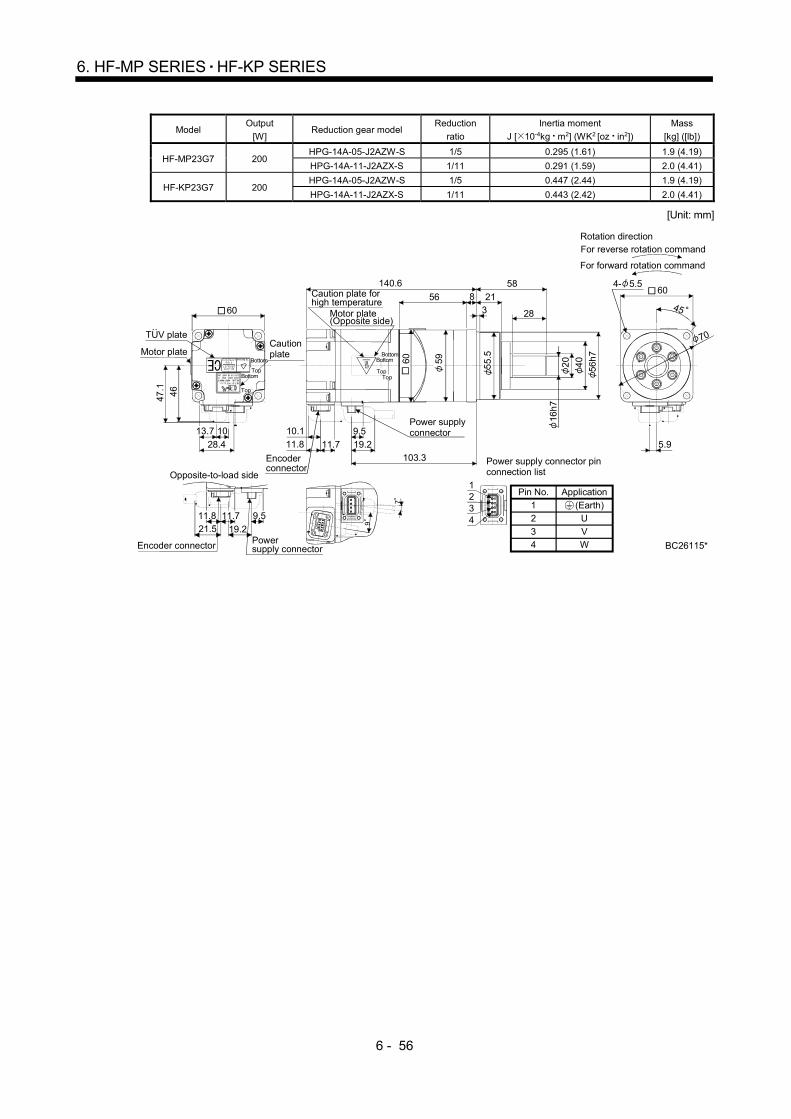
6 - 56
6. HF-MP SERIES HF-KP SERIES
Model Output
[W] Reduction gear model
Reduction
ratio
Inertia moment
J [ 10-4kg m2] (WK2 [oz in2])
Mass
[kg] ([lb])
HF-MP23G7 200 HPG-14A-05-J2AZW-S 1/5 0.295 (1.61) 1.9 (4.19)
HPG-14A-11-J2AZX-S 1/11 0.291 (1.59) 2.0 (4.41)
HF-KP23G7 200 HPG-14A-05-J2AZW-S 1/5 0.447 (2.44) 1.9 (4.19)
HPG-14A-11-J2AZX-S 1/11 0.443 (2.42) 2.0 (4.41)
[Unit: mm]
BC26115*
7
9
19.221.511.8 11.7 9.5
46
28.4
10
47.1
13.7
Top
70
5.9
60
11.8 19.2
10.1
58
28
56 213
8
140.6
103.3
16h
7
40
56h
7
9.5
11.7
2060 59
55
.5BottomMotor plateCaution plate
Top
Bottom
60
Bottom
Caution plate for high temperature
Motor plate(Opposite side)
Encoder connector
Bottom
TopTop
Power supply connector
45
4- 5.5
Rotation direction
For forward rotation command
For reverse rotation command
Power supply connectorEncoder connector
Opposite-to-load side
TUV plate
(Earth)
Power supply connector pinconnection list
42
31
1234
ApplicationPin No.
12
34
U
VW
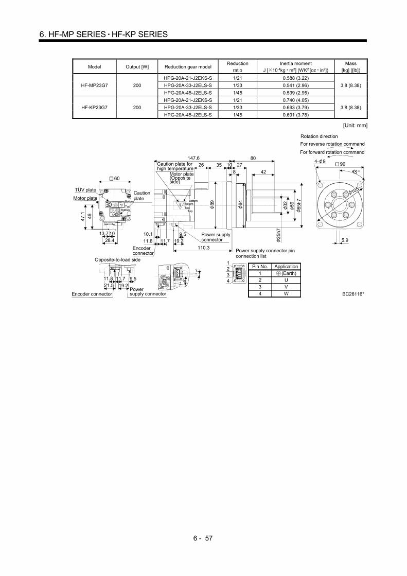
6 - 57
6. HF-MP SERIES HF-KP SERIES
Model Output [W] Reduction gear model Reduction
ratio
Inertia moment
J [ 10-4kg m2] (WK2 [oz in2])
Mass
[kg] ([lb])
HF-MP23G7 200
HPG-20A-21-J2EKS-S 1/21 0.588 (3.22)
3.8 (8.38) HPG-20A-33-J2ELS-S 1/33 0.541 (2.96)
HPG-20A-45-J2ELS-S 1/45 0.539 (2.95)
HF-KP23G7 200
HPG-20A-21-J2EKS-S 1/21 0.740 (4.05)
3.8 (8.38) HPG-20A-33-J2ELS-S 1/33 0.693 (3.79)
HPG-20A-45-J2ELS-S 1/45 0.691 (3.78)
[Unit: mm]
BC26116*
7
9
19.221.59.511.8 11.7
28.4
10
46
47.1
13.7
105
5.9
90
25
h7
59
85h7
19.2
10.1
1026 2780
8 42
147.6
110.311.8 11.7
9.5
32
35
84
89Bottom
TopTop
Motor plateCaution plate
Top
Bottom
60
BottomTop
Caution plate for high temperature
Motor plate(Opposite side)
Bottom
Encoder connector
Rotation direction
For forward rotation command
For reverse rotation command
4- 9
45
Encoder connectorPower supply connector
Opposite-to-load side
TUV plate
(Earth)
Power supply connector pinconnection list
42
31
1234
ApplicationPin No.
12
34
U
VW
Power supply connector
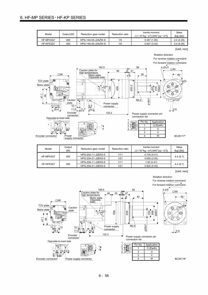
6 - 58
6. HF-MP SERIES HF-KP SERIES
Model Output [W] Reduction gear model Reduction ratio Inertia moment
J [ 10-4kg m2] (WK2 [oz in2])
Mass
[kg] ([lb])
HF-MP43G7 400 HPG-14A-05-J2AZW-S 1/5 0.357 (1.95) 2.4 (5.29)
HF-KP43G7 400 HPG-14A-05-J2AZW-S 1/5 0.627 (3.43) 2.4 (5.29)
[Unit: mm]
BC26117*
7
919.221.59.511.8 11.7
46
28.4
10
47
.1
13.7
70
5.9Encoder connector
11.8 19.2
10.1
58
28
56 213
8
162.5
125.2
16
h7
40 56h
7
11.7
9.5
2060
59 55.5
R0.4
Top
Power supply connector
Motor plate
Caution plate
Bottom
60
TopBottom
Top
Caution plate for high temperature
Motor plate(Opposite side)
BottomBottom
Top
Rotation direction
For forward rotation command
For reverse rotation command
4- 5.560
45
Power supply connector
Encoder connector
Opposite-to-load side
TUV plate
(Earth)
Power supply connector pinconnection list
42
31
1234
ApplicationPin No.
1
23
4
UV
W
Model Output
[W] Reduction gear model Reduction ratio
Inertia moment
J [ 10-4kg m2] (WK2 [oz in2])
Mass
[kg] ([lb])
HF-MP43G7 400 HPG-20A-11-J2EKS-S 1/11 0.734 (4.01)
4.4 (9.7) HPG-20A-21-J2EKS-S 1/21 0.650 (3.55)
HF-KP43G7 400 HPG-20A-11-J2EKS-S 1/11 1.00 (5.47)
4.4 (9.7) HPG-20A-21-J2EKS-S 1/21 0.920 (5.03)
[Unit: mm]
BC26118*
7
9
21.59.519.211.8
11.7
47.
1
46
10
28.4
13.7
105
5.9
25
h7
59 85h7
42
80
26
8
2710
19.211.8
10.1
169.5
132.2
11.7
9.5
32
R0.4
35
8489BottomTop
Motor plate
60
Caution plate
BottomTop
Bottom
Top
Encoder connector
Caution plate for high temperature
Motor plate(Opposite side)
Bottom
Top
Power supply connector
Rotation direction
For forward rotation command
For reverse rotation command
4- 990
45
Power supply connectorEncoder connector
Opposite-to-load side
TUV plate
(Earth)
Power supply connector pinconnection list
42
31
1234
ApplicationPin No.
12
34
U
VW
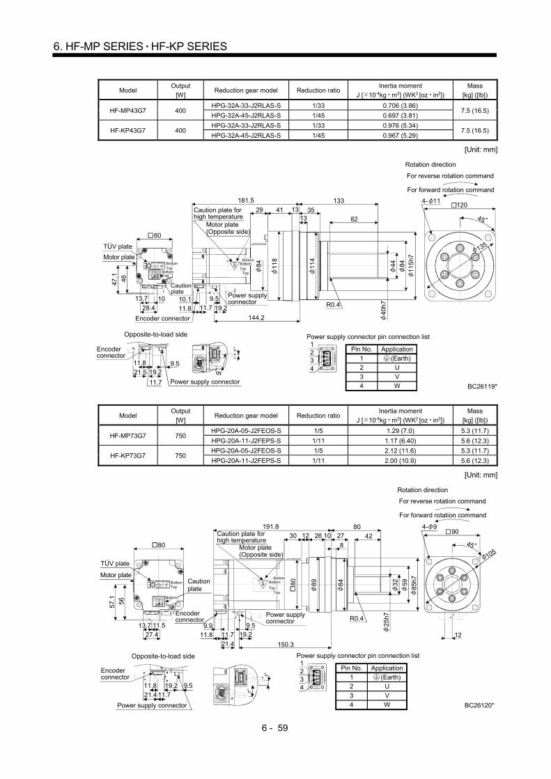
6 - 59
6. HF-MP SERIES HF-KP SERIES
Model Output
[W] Reduction gear model Reduction ratio
Inertia moment
J [ 10-4kg m2] (WK2 [oz in2])
Mass
[kg] ([lb])
HF-MP43G7 400 HPG-32A-33-J2RLAS-S 1/33 0.706 (3.86)
7.5 (16.5) HPG-32A-45-J2RLAS-S 1/45 0.697 (3.81)
HF-KP43G7 400 HPG-32A-33-J2RLAS-S 1/33 0.976 (5.34)
7.5 (16.5) HPG-32A-45-J2RLAS-S 1/45 0.967 (5.29)
[Unit: mm]
(Earth)
Power supply connector pin connection list
42
31
1234
ApplicationPin No.
12
34
U
VW
Top
BC26119*
1204- 11
45
7
9
9.521.5
11.7
11.8
10.1
35
133
41 1313 82
181.5
144.2
40h
7
8411
5h7
29
84
118
114
44
R0.4
47.1
46
1028.4
60
9.5
TopBottom
BottomTopBottom
Top
Bottom
For forward rotation command
For reverse rotation command
Rotation direction
Opposite-to-load side
Motor plate(Opposite side)
Caution plate for high temperature
Motor plate
TUV plate
Encoder connector
Encoder connector
Power supply connector
Power supply connector
Caution plate
19.2
19.2
135
13.7
11.7
11.8
Model Output
[W] Reduction gear model Reduction ratio
Inertia moment
J [ 10-4kg m2] (WK2 [oz in2])
Mass
[kg] ([lb])
HF-MP73G7 750 HPG-20A-05-J2FEOS-S 1/5 1.29 (7.0) 5.3 (11.7)
HPG-20A-11-J2FEPS-S 1/11 1.17 (6.40) 5.6 (12.3)
HF-KP73G7 750 HPG-20A-05-J2FEOS-S 1/5 2.12 (11.6) 5.3 (11.7)
HPG-20A-11-J2FEPS-S 1/11 2.00 (10.9) 5.6 (12.3)
[Unit: mm]
(Earth)
Power supply connector pin connection list
42
31
1234
ApplicationPin No.
12
34
U
VW BC26120*
56
27.4
11.5
57.
1
80
7
7
904- 9
10545
12
9.511.721.4
25h7
59
85h
7
11.89.9
21.4
27
8
10 42
8030
191.8
150.3
3280 89
84
12 26
R0.4
11.7
9.5
TopBottom
Top
Bottom
Top
Bottom
Top
Bottom
For forward rotation command
For reverse rotation command
Rotation direction
Opposite-to-load side
Motor plate(Opposite side)
Caution plate for high temperature
Motor plate
TUV plate
Encoder connector
Encoder connector
Power supply connector
Power supply connector
Caution plate
13.7
11.8 19.2
19.2
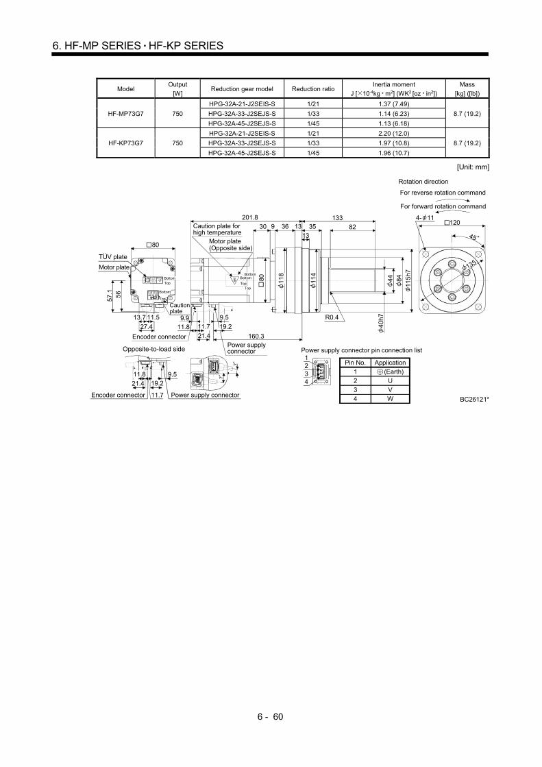
6 - 60
6. HF-MP SERIES HF-KP SERIES
Model Output
[W] Reduction gear model Reduction ratio
Inertia moment
J [ 10-4kg m2] (WK2 [oz in2])
Mass
[kg] ([lb])
HF-MP73G7 750
HPG-32A-21-J2SEIS-S 1/21 1.37 (7.49)
8.7 (19.2) HPG-32A-33-J2SEJS-S 1/33 1.14 (6.23)
HPG-32A-45-J2SEJS-S 1/45 1.13 (6.18)
HF-KP73G7 750
HPG-32A-21-J2SEIS-S 1/21 2.20 (12.0)
8.7 (19.2) HPG-32A-33-J2SEJS-S 1/33 1.97 (10.8)
HPG-32A-45-J2SEJS-S 1/45 1.96 (10.7)
[Unit: mm]
(Earth)
Power supply connector pin connection list
42
31
1234
ApplicationPin No.
12
34
U
VW
11
4
BC26121*
9.5
7
7120
4- 11
45
135
40h
7
84
115
h7
11.89.9
13
133
829 3630 13 35
201.8
160.3
44
56
27.4
13.7
57.1
80
118
80
R0.4
11.7
9.5
TopBottom
Top
Bottom
Top
Bottom
Top
Bottom
For forward rotation command
For reverse rotation command
Rotation direction
Opposite-to-load side
Motor plate(Opposite side)
Caution plate for high temperature
Motor plate
TUV plate
Encoder connector
Encoder connector
Power supply connector
Power supply connector
Caution plate
21.4
11.8
11.7 19.2
21.4 19.2
11.5
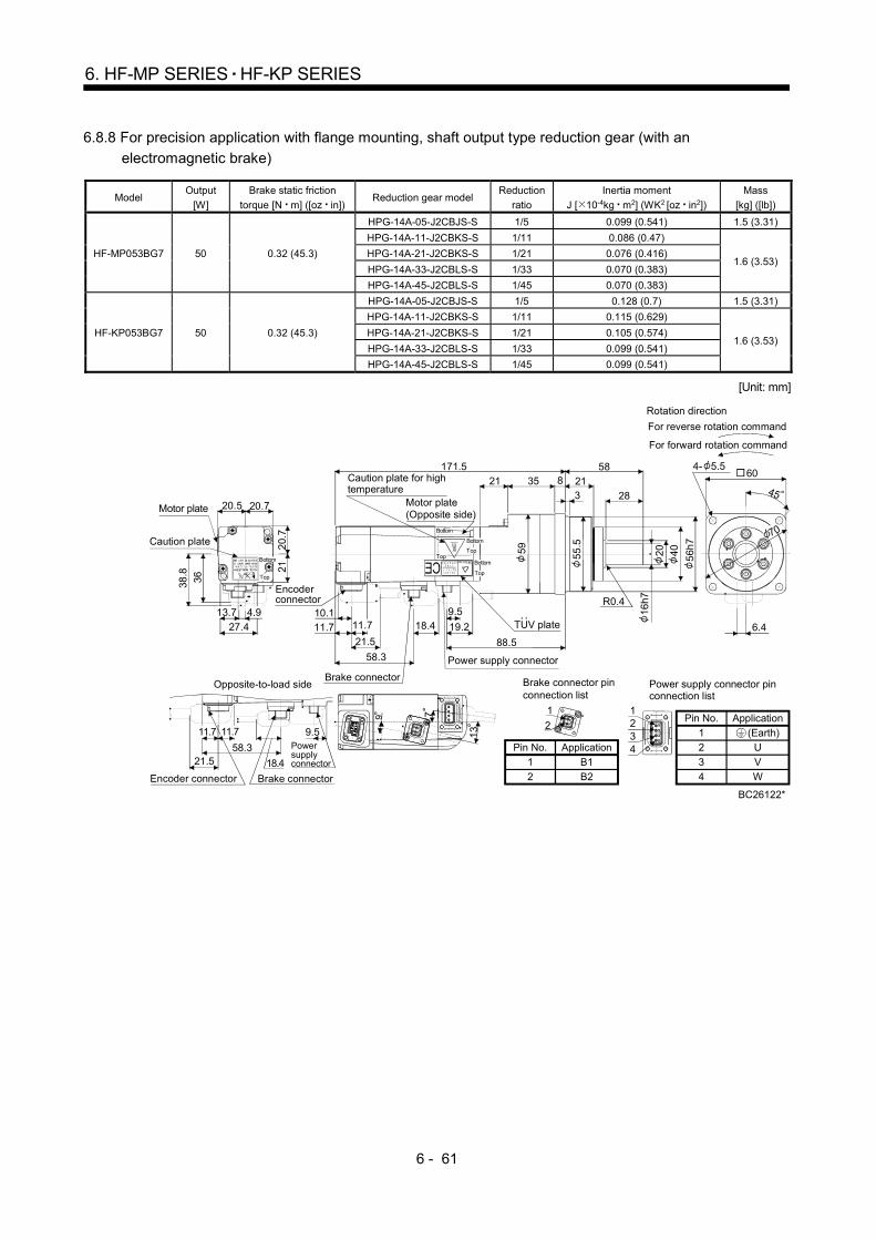
6 - 61
6. HF-MP SERIES HF-KP SERIES
6.8.8 For precision application with flange mounting, shaft output type reduction gear (with an
electromagnetic brake)
Model Output
[W]
Brake static friction
torque [N m] ([oz in]) Reduction gear model
Reduction
ratio
Inertia moment
J [ 10-4kg m2] (WK2 [oz in2])
Mass
[kg] ([lb])
HF-MP053BG7 50 0.32 (45.3)
HPG-14A-05-J2CBJS-S 1/5 0.099 (0.541) 1.5 (3.31)
HPG-14A-11-J2CBKS-S 1/11 0.086 (0.47)
1.6 (3.53) HPG-14A-21-J2CBKS-S 1/21 0.076 (0.416)
HPG-14A-33-J2CBLS-S 1/33 0.070 (0.383)
HPG-14A-45-J2CBLS-S 1/45 0.070 (0.383)
HF-KP053BG7 50 0.32 (45.3)
HPG-14A-05-J2CBJS-S 1/5 0.128 (0.7) 1.5 (3.31)
HPG-14A-11-J2CBKS-S 1/11 0.115 (0.629)
1.6 (3.53) HPG-14A-21-J2CBKS-S 1/21 0.105 (0.574)
HPG-14A-33-J2CBLS-S 1/33 0.099 (0.541)
HPG-14A-45-J2CBLS-S 1/45 0.099 (0.541)
[Unit: mm]
(Earth)
Power supply connector pinconnection list
42
31
1234
ApplicationPin No.
12
3
4
U
V
W
Pin No.
1
2
Application
B1
B2
BC26122*
Brake connector pin connection list
2
1
21
18.421.558.3
7
21
13
36
27.4
13.7
20.720.5
212
0.7
38.8
604- 5.5
45
70
6.4
Motor plate(Opposite side)
Caution plate for high temperature
16h7
40
56h
7
9.5
11.7
58.3
19.2
21.5
10.118.4
321
58821
28
88.5
171.5
20
35
55
.5
59
R0.4
9.511.711.7
4.911.7
Motor plate
Caution plate
Top
Bottom
Bottom
Top
Bottom
Top
Encoder connector
Power supply connector
Brake connector
For forward rotation command
For reverse rotation command
Rotation direction
Opposite-to-load side
Power supplyconnector
Encoder connector Brake connector
9
TUV plate
Top
Bottom
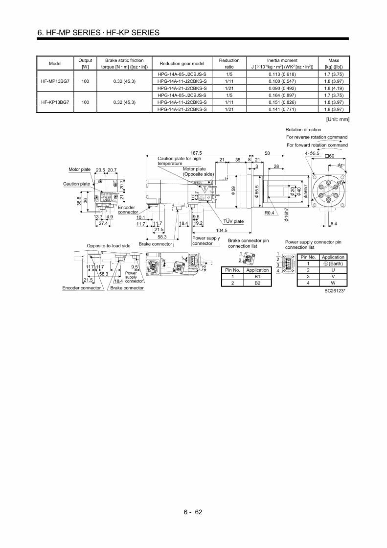
6 - 62
6. HF-MP SERIES HF-KP SERIES
Model Output
[W]
Brake static friction
torque [N m] ([oz in]) Reduction gear model
Reduction
ratio
Inertia moment
J [ 10-4kg m2] (WK2 [oz in2])
Mass
[kg] ([lb])
HF-MP13BG7 100 0.32 (45.3)
HPG-14A-05-J2CBJS-S 1/5 0.113 (0.618) 1.7 (3.75)
HPG-14A-11-J2CBKS-S 1/11 0.100 (0.547) 1.8 (3.97)
HPG-14A-21-J2CBKS-S 1/21 0.090 (0.492) 1.8 (4.19)
HF-KP13BG7 100 0.32 (45.3)
HPG-14A-05-J2CBJS-S 1/5 0.164 (0.897) 1.7 (3.75)
HPG-14A-11-J2CBKS-S 1/11 0.151 (0.826) 1.8 (3.97)
HPG-14A-21-J2CBKS-S 1/21 0.141 (0.771) 1.8 (3.97)
[Unit: mm]
BC26123*
2
1
21
36
27.4
38.
8
13.7
20.720.5
2120
.7
18.421.558.3
79
13
21
604- 5.5
45
70
6.4
16h7
40 56h7
9.5
11.7 11.7
58.3
19.221.5
10.118.4
58
21
3
35 8
28
187.5
104.5
21
59
55.5
R0.4
20
9.511.711.7
4.9
For forward rotation command
For reverse rotation command
Rotation direction
Brake connector pin connection list
Motor plate(Opposite side)
Caution plate for high temperature
Motor plate
Caution plate
Top
Bottom
Bottom
Top
Bottom
Top
Encoder connector
Power supply connectorBrake connectorOpposite-to-load side
Power supplyconnector
Encoder connector Brake connector
TUV plate
Top
Bottom
(Earth)
Power supply connector pinconnection list
42
31
1234
ApplicationPin No.
12
3
4
U
V
W
Pin No.
1
2
Application
B1
B2

6 - 63
6. HF-MP SERIES HF-KP SERIES
Model Output
[W]
Brake static friction
torque [N m] ([oz in]) Reduction gear model
Reduction
ratio
Inertia moment
J [ 10-4kg m2] (WK2 [oz in2])
Mass
[kg] ([lb])
HF-MP13BG7 100 0.32 (45.3) HPG-20A-33-J2JMLAS-S 1/33 0.102 (0.558)
3.3 (7.28) HPG-20A-45-J2JMLAS-S 1/45 0.100 (0.547)
HF-KP13BG7 100 0.32 (45.3) HPG-20A-33-J2JMLAS-S 1/33 0.153 (0.837)
3.3 (7.28) HPG-20A-45-J2JMLAS-S 1/45 0.151 (0.826)
[Unit: mm]
BC26124*
2
1
21
79
13
21
9.5
18.4
11.7 11.7
21.5
58.3
36
4.9
27.4
38.8
13.7
20.720.5
2120
.7
25h7 59
85h
7
9.5
11.7 11.7
58.3
19.221.5
18.4
8027
8
26 10
42
190
107
904- 9
45
105
R0.410.1
30.5
3255 89 84
Motor plate
Caution plate
Top
Bottom
Encoder connector
Motor plate(Opposite side)
Caution plate for high temperature
Bottom
Top
Bottom
Top
Top
Bottom
Power supply connectorBrake connector
TUV plate
For forward rotation command
For reverse rotation command
Rotation direction
Opposite-to-load side
Power supplyconnector
Encoder connector Brake connector
Brake connector pin connection list
(Earth)
Power supply connector pinconnection list
42
31
1234
ApplicationPin No.
12
3
4
U
V
W
Pin No.
1
2
Application
B1
B2

6 - 64
6. HF-MP SERIES HF-KP SERIES
Model Output
[W]
Brake static friction
torque [N m] ([oz in]) Reduction gear model
Reduction
ratio
Inertia moment
J [ 10-4kg m2] (WK2 [oz in2])
Mass
[kg] ([lb])
HF-MP23BG7 200 1.3 (184) HPG-14A-05-J2AZW-S 1/5 0.327 (1.79) 2.5 (5.51)
HPG-14A-11-J2AZX-S 1/11 0.323 (1.77) 2.6 (5.73)
HF-KP23BG7 200 1.3 (184) HPG-14A-05-J2AZW-S 1/5 0.517 (2.83) 2.5 (5.51)
HPG-14A-11-J2AZX-S 1/11 0.513 (2.81) 2.6 (5.73)
[Unit: mm]]
BC26125*
2
1
21
9.5
18.3
11.7
21.557.8
604- 5.5
45
70
5.9
46
28.4
10
47.1
60
16h
7
40 56h
7
9.5
11.8 11.7
57.8
19.221.5
5821
3
56 8
28
180.1
10.1
103.3
20
R0.4
55.5
5960
13.7
11.8
7
9
13.5
For forward rotation command
For reverse rotation command
Rotation direction
TUV plate
Motor plateCaution plate
Encoder connector
Top
Bottom
Motor plate(Opposite side)
Caution plate for high temperature
Top
Bottom
Power supply connector
Brake connector
Bottom
Top
Brake connector pin connection listOpposite-to-load side
Power supplyconnector
Encoder connector Brake connector
Top
Bottom
(Earth)
Power supply connector pinconnection list
42
31
1234
ApplicationPin No.
12
3
4
U
V
W
Pin No.
1
2
Application
B1
B2

6 - 65
6. HF-MP SERIES HF-KP SERIES
Model Output
[W]
Brake static friction
torque [N m] ([oz in]) Reduction gear model
Reduction
ratio
Inertia moment
J [ 10-4kg m2] (WK2 [oz in2])
Mass
[kg] ([lb])
HF-MP23BG7 200 1.3 (184)
HPG-20A-21-J2EKS-S 1/21 0.620 (3.39)
4.5 (9.92) HPG-20A-33-J2ELS-S 1/33 0.573 (3.13)
HPG-20A-45-J2ELS-S 1/45 0.571 (3.12)
HF-KP23BG7 200 1.3 (184)
HPG-20A-21-J2EKS-S 1/21 0.810 (4.43)
4.5 (9.92) HPG-20A-33-J2ELS-S 1/33 0.763 (4.17)
HPG-20A-45-J2ELS-S 1/45 0.761 (4.16)
[Unit: mm]
BC26126*
2
1
21
9.5
18.3
11.8 11.7
21.5
57.8
7
9
13.5
904- 9
45
105
25h
7
59 85h7
9.5
11.8 11.7
57.8
19.221.5
8027
835 10
42
187.1
10.1
110.3
328489
26
R0.4
46
28.4
1013.7
47.1
60
For forward rotation command
For reverse rotation command
Rotation direction
TUV plate
Motor plate Caution plate
Encoder connector
Top
Bottom
Top
Bottom
Motor plate(Opposite side)
Caution plate for high temperature
Top
Bottom
Power supply connector
Brake connector
Bottom
Top
Brake connector pin connection listOpposite-to-load side
Power supplyconnector
Encoder connector Brake connector
(Earth)
Power supply connector pinconnection list
42
31
1234
ApplicationPin No.
12
34
U
VW
Pin No.
1
2
Application
B1
B2
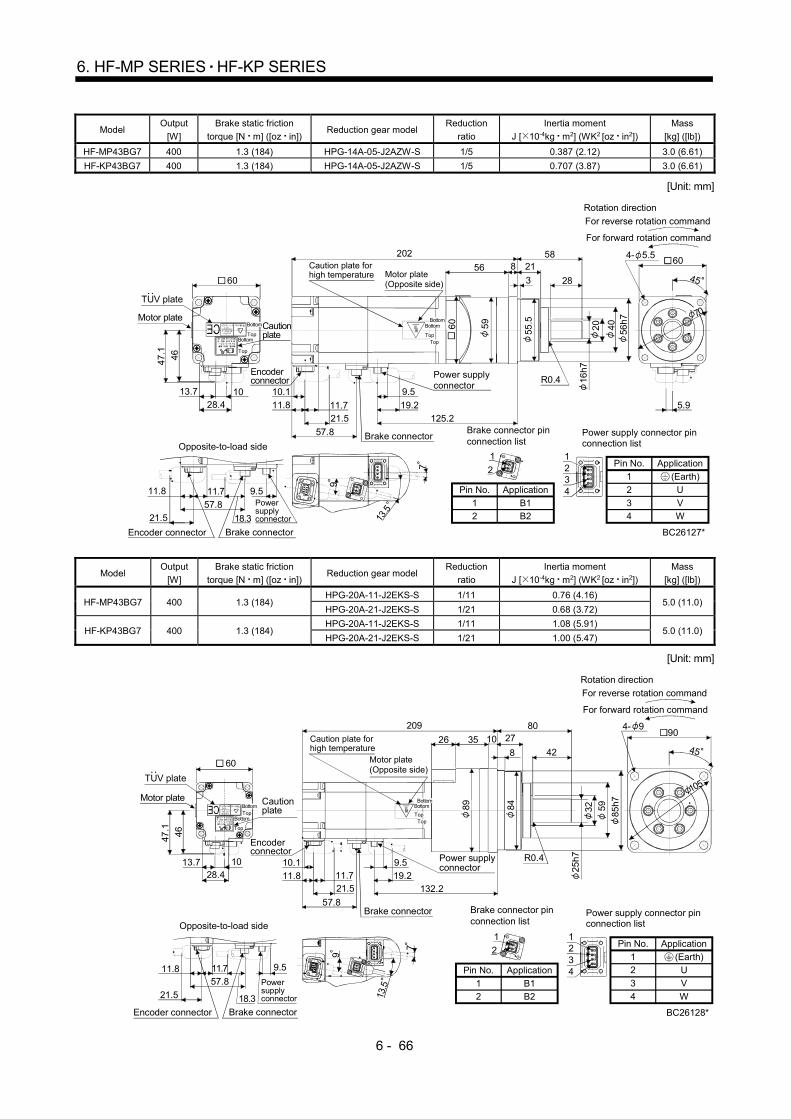
6 - 66
6. HF-MP SERIES HF-KP SERIES
Model Output
[W]
Brake static friction
torque [N m] ([oz in]) Reduction gear model
Reduction
ratio
Inertia moment
J [ 10-4kg m2] (WK2 [oz in2])
Mass
[kg] ([lb])
HF-MP43BG7 400 1.3 (184) HPG-14A-05-J2AZW-S 1/5 0.387 (2.12) 3.0 (6.61)
HF-KP43BG7 400 1.3 (184) HPG-14A-05-J2AZW-S 1/5 0.707 (3.87) 3.0 (6.61)
[Unit: mm]
BC26127*
2
1
21
7
9
13.5
604- 5.5
45
70
5.9
16h7
40
56h
7
9.5
11.8
57.8
19.2
21.5
5821
356 8
28
202
10.1
125.2
5960
55.5
20
R0.4
11.7
9.5
18.3
11.8 11.7
21.5
57.8
46
28.41013.7
47.
1
60
For forward rotation command
For reverse rotation command
Rotation direction
TUV plate
Motor plateCaution plate
Encoder connector
Top
Bottom
Top
Bottom
Motor plate(Opposite side)
Caution plate for high temperature
Top
Bottom
Power supply connector
Brake connector
Bottom
Top
Brake connector pin connection listOpposite-to-load side
Power supplyconnector
Encoder connector Brake connector
(Earth)
Power supply connector pinconnection list
42
31
1234
ApplicationPin No.
1
2
3
4
U
V
W
Pin No.
1
2
Application
B1
B2
Model Output
[W]
Brake static friction
torque [N m] ([oz in]) Reduction gear model
Reduction
ratio
Inertia moment
J [ 10-4kg m2] (WK2 [oz in2])
Mass
[kg] ([lb])
HF-MP43BG7 400 1.3 (184) HPG-20A-11-J2EKS-S 1/11 0.76 (4.16)
5.0 (11.0) HPG-20A-21-J2EKS-S 1/21 0.68 (3.72)
HF-KP43BG7 400 1.3 (184) HPG-20A-11-J2EKS-S 1/11 1.08 (5.91)
5.0 (11.0) HPG-20A-21-J2EKS-S 1/21 1.00 (5.47)
[Unit: mm]
BC26128*
2
1
21
46
28.41013.7
47.1
60
7
9
13.5
25h7
59
85h7
9.5
11.8 11.7
57.8
19.221.5
8027
835 10
42
209
10.1
132.2
9.5
18.3
11.8 11.7
21.5
57.8
904- 9
45
105
26
89 84 32
R0.4
For forward rotation command
For reverse rotation command
Rotation direction
TUV plate
Motor plate Caution plate
Encoder connector
TopBottom
Top
Bottom
Motor plate(Opposite side)
Caution plate for high temperature
Top
Bottom
Power supply connector
Brake connector
Bottom
Top
Brake connector pin connection listOpposite-to-load side
Power supplyconnector
Encoder connector Brake connector
(Earth)
Power supply connector pinconnection list
42
31
1234
ApplicationPin No.
12
3
4
U
V
W
Pin No.
1
2
Application
B1
B2

6 - 67
6. HF-MP SERIES HF-KP SERIES
Model Output
[W]
Brake static friction
torque [N m] ([oz in]) Reduction gear model
Reduction
ratio
Inertia moment
J [ 10-4kg m2] (WK2 [oz in2])
Mass
[kg] ([lb])
HF-MP43BG7 400 1.3 (184) HPG-32A-33-J2RLAS-S 1/33 0.74 (4.05)
8.1 (17.9) HPG-32A-45-J2RLAS-S 1/45 0.73 (3.99)
HF-KP43BG7 400 1.3 (184) HPG-32A-33-J2RLAS-S 1/33 1.06 (5.80)
8.1 (17.9) HPG-32A-45-J2RLAS-S 1/45 1.05 (5.74)
[Unit: mm]
BC26129*
2
1
21
7
9
13.5
9.5
18.3
11.811.7
21.5
57.8
1204- 11
45
46
28.41013.7
47.
1
40
h7
84
115h
7
11.8
57.8
19.2
21.5
13335
1341 13
82
221
10.1
144.211.7
60
29
84 118
114
R0.4
44
9.5
135
For forward rotation command
For reverse rotation command
Rotation direction
TUV plate
Motor plate Caution plate
Encoder connector
Bottom
Top
BottomTop
Motor plate(Opposite side)
Caution plate for high temperature
TopBottom
Power supply connector
Brake connector
Bottom
Top
Brake connector pin connection listOpposite-to-load side
Power supplyconnector
Encoder connector Brake connector
(Earth)
Power supply connector pinconnection list
42
31
1234
ApplicationPin No.
1
2
3
4
U
V
W
Pin No.
1
2
Application
B1
B2

6 - 68
6. HF-MP SERIES HF-KP SERIES
Model Output
[W]
Brake static friction
torque [N m] ([oz in]) Reduction gear model
Reduction
ratio
Inertia moment
J [ 10-4kg m2] (WK2 [oz in2])
Mass
[kg] ([lb])
HF-MP73BG7 750 2.4 (340) HPG-20A-05-J2FEOS-S 1/5 1.39 (7.6) 6.3 (13.9)
HPG-20A-11-J2FEPS-S 1/11 1.27 (6.94) 6.6 (14.6)
HF-KP73BG7 750 2.4 (340) HPG-20A-05-J2FEOS-S 1/5 2.32 (12.7) 6.3 (13.9)
HPG-20A-11-J2FEPS-S 1/11 2.20 (12.0) 6.6 (14.6)
[Unit: mm]
BC26130*
2
1
21
56
27.4
11.513.7
57.
1
7
77
9.5
18.4
11.8
21.4
65.511.7
904- 9
45
105
12
25h
7
9.5
11.8
65.5
19.2
21.4
8027
8
30 10
42
233
150.311.7
12 26
80
9.9
59
85h
7
3280 89 84
R0.4
For forward rotation command
For reverse rotation command
Rotation direction
TUV plate
Motor plateCaution plate
Encoder connector
TopBottom
Top
Bottom
Motor plate(Opposite side)
Caution plate for high temperature
TopBottom
Power supply connector
Brake connector
Bottom
Top
89Brake connector pin connection listOpposite-to-load side
Power supplyconnector
Encoder connector Brake connector
(Earth)
Power supply connector pinconnection list
42
31
1234
ApplicationPin No.
12
3
4
U
V
W
Pin No.
1
2
Application
B1
B2
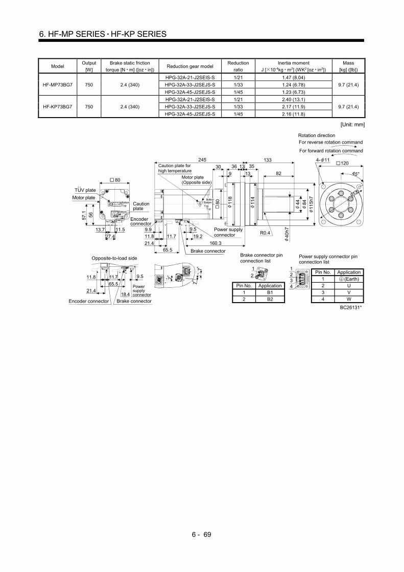
6 - 69
6. HF-MP SERIES HF-KP SERIES
Model Output
[W]
Brake static friction
torque [N m] ([oz in]) Reduction gear model
Reduction
ratio
Inertia moment
J [ 10-4kg m2] (WK2 [oz in2])
Mass
[kg] ([lb])
HF-MP73BG7 750 2.4 (340)
HPG-32A-21-J2SEIS-S 1/21 1.47 (8.04)
9.7 (21.4) HPG-32A-33-J2SEJS-S 1/33 1.24 (6.78)
HPG-32A-45-J2SEJS-S 1/45 1.23 (6.73)
HF-KP73BG7 750 2.4 (340)
HPG-32A-21-J2SEIS-S 1/21 2.40 (13.1)
9.7 (21.4) HPG-32A-33-J2SEJS-S 1/33 2.17 (11.9)
HPG-32A-45-J2SEJS-S 1/45 2.16 (11.8)
[Unit: mm]
BC26131*
2
1
21
7
77
9.5
18.4
11.8
21.4
65.5
11.7
45
1204- 11
135
84
11.8
65.5
19.2
13335
13
36
82
245
160.3
11.7
21.4
11
5h7
40h
7
30
9
13
80 118
114
56
27.4
11.513.7
57.1
80
44
R0.49.9 9.5
For forward rotation command
For reverse rotation command
Rotation direction
TUV plate
Motor plateCaution plate
Encoder connector
TopBottom
Top
Bottom
Motor plate(Opposite side)
Caution plate for high temperature
TopBottom
Power supply connector
Brake connector
Bottom
Top
Brake connector pin connection list
Opposite-to-load side
Power supplyconnector
Encoder connector Brake connector
(Earth)
Power supply connector pinconnection list
42
31
1234
ApplicationPin No.
12
34
U
VW
Pin No.
1
2
Application
B1
B2

6 - 70
6. HF-MP SERIES HF-KP SERIES
MEMO
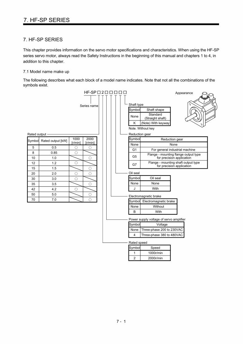
7 - 1
7. HF-SP SERIES
7. HF-SP SERIES
This chapter provides information on the servo motor specifications and characteristics. When using the HF-SP
series servo motor, always read the Safety Instructions in the beginning of this manual and chapters 1 to 4, in
addition to this chapter. 7.1 Model name make up
The following describes what each block of a model name indicates. Note that not all the combinations of the symbols exist.
Note. Without key
None Without
Electromagnetic brake
Symbol Electromagnetic brake
B With
HF-SP
Series name Shaft type
Symbol Shaft shape
NoneStandard
(Straight shaft)
K (Note) With keyway
Appearance
1 1000r/min
Rated speed
Symbol Speed
2 2000r/min
None
Reduction gear
Symbol
G1 For general industrial machine
Flange - mounting flange output type for precision application
Reduction gear
None
G5
G7Flange - mounting shaft output type
for precision application
5 0.5
Rated output
Symbol Rated output [kW]1000
[r/min]2000[r/min]
8 0.85
10 1.0
12 1.2
15 1.5
20 2.0
30 3.0
35 3.5
42 4.2
70 7.0
50 5.0
None Three-phase 200 to 230VAC
Power supply voltage of servo amplifier
Symbol Voltage
4 Three-phase 380 to 480VAC
None None
Oil seal
Symbol Oil seal
J With
2
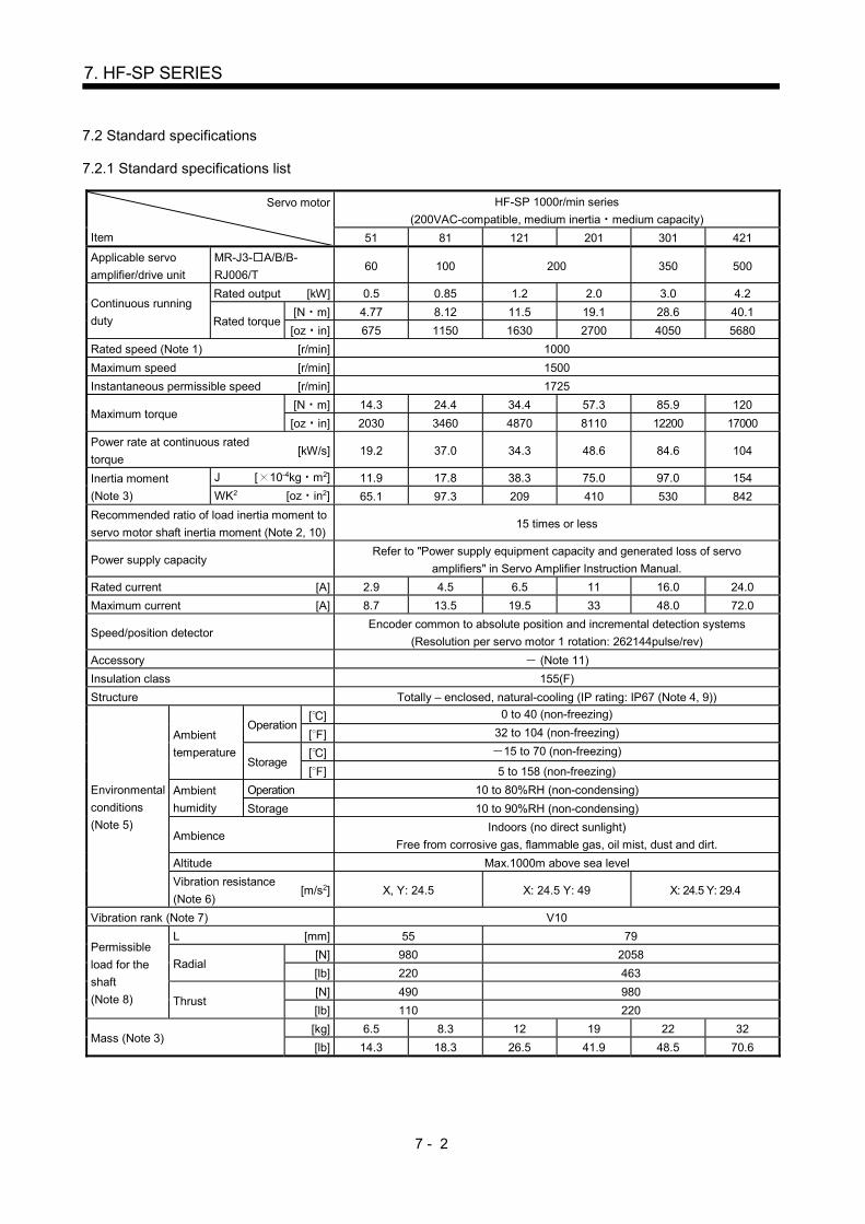
7 - 2
7. HF-SP SERIES
7.2 Standard specifications
7.2.1 Standard specifications list
Servo motor
Item
HF-SP 1000r/min series
(200VAC-compatible, medium inertia medium capacity)
51 81 121 201 301 421
Applicable servo
amplifier/drive unit
MR-J3- A/B/B-
RJ006/T 60 100 200 350 500
Continuous running
duty
Rated output [kW] 0.5 0.85 1.2 2.0 3.0 4.2
Rated torque [N m] 4.77 8.12 11.5 19.1 28.6 40.1
[oz in] 675 1150 1630 2700 4050 5680
Rated speed (Note 1) [r/min] 1000
Maximum speed [r/min] 1500
Instantaneous permissible speed [r/min] 1725
Maximum torque [N m] 14.3 24.4 34.4 57.3 85.9 120
[oz in] 2030 3460 4870 8110 12200 17000
Power rate at continuous rated
torque [kW/s] 19.2 37.0 34.3 48.6 84.6 104
Inertia moment
(Note 3)
J [ 10-4kg m2] 11.9 17.8 38.3 75.0 97.0 154
WK2 [oz in2] 65.1 97.3 209 410 530 842
Recommended ratio of load inertia moment to
servo motor shaft inertia moment (Note 2, 10) 15 times or less
Power supply capacity Refer to "Power supply equipment capacity and generated loss of servo
amplifiers" in Servo Amplifier Instruction Manual.
Rated current [A] 2.9 4.5 6.5 11 16.0 24.0
Maximum current [A] 8.7 13.5 19.5 33 48.0 72.0
Speed/position detector Encoder common to absolute position and incremental detection systems
(Resolution per servo motor 1 rotation: 262144pulse/rev)
Accessory (Note 11)
Insulation class 155(F)
Structure Totally – enclosed, natural-cooling (IP rating: IP67 (Note 4, 9))
Environmental
conditions
(Note 5)
Ambient
temperature
Operation [ ] 0 to 40 (non-freezing)
[ ] 32 to 104 (non-freezing)
Storage [ ] 15 to 70 (non-freezing)
[ ] 5 to 158 (non-freezing)
Ambient
humidity
Operation 10 to 80%RH (non-condensing)
Storage 10 to 90%RH (non-condensing)
Ambience Indoors (no direct sunlight)
Free from corrosive gas, flammable gas, oil mist, dust and dirt.
Altitude Max.1000m above sea level
Vibration resistance
(Note 6) [m/s2] X, Y: 24.5 X: 24.5 Y: 49 X: 24.5 Y: 29.4
Vibration rank (Note 7) V10
Permissible
load for the
shaft
(Note 8)
L [mm] 55 79
Radial [N] 980 2058
[lb] 220 463
Thrust [N] 490 980
[lb] 110 220
Mass (Note 3) [kg] 6.5 8.3 12 19 22 32
[lb] 14.3 18.3 26.5 41.9 48.5 70.6

7 - 3
7. HF-SP SERIES
Servo motor
Item
HF-SP 2000r/min series
(200VAC-compatible, medium inertia medium capacity)
52 102 152 202 352 502 702
Applicable servo
amplifier/drive unit
MR-J3- A/B/B-
RJ006/T 60 100 200 200 350 500 700
Continuous running
duty
Rated output [kW] 0.5 1.0 1.5 2 3.5 5.0 7.0
Rated torque [N m] 2.39 4.77 7.16 9.55 16.7 23.9 33.4
[oz in] 338 675 1010 1350 2360 3380 4730
Rated speed (Note 1) [r/min] 2000
Maximum speed [r/min] 3000
Instantaneous permissible speed [r/min] 3450
Maximum torque [N m] 7.16 14.3 21.5 28.6 50.1 71.6 100
[oz in] 1010 2030 3040 4050 7090 10100 14200
Power rate at continuous rated
torque [kW/s] 9.34 19.2 28.8 23.8 37.2 58.8 72.5
Inertia moment
(Note 3)
J [ 10-4kg m2] 6.1 11.9 17.8 38.3 75.0 97.0 154
WK2 [oz in2] 33.4 65.1 97.3 209 410 530 842
Recommended ratio of load inertia moment to
servo motor shaft inertia moment (Note 2, 10) 15 times or less
Power supply capacity Refer to "Power supply equipment capacity and generated loss of servo
amplifiers" in Servo Amplifier Instruction Manual.
Rated current [A] 2.9 5.3 8.0 10 16 24 33
Maximum current [A] 8.7 15.9 2.4 30 48 72 99
Speed/position detector Encoder common to absolute position and incremental detection systems
(Resolution per servo motor 1 rotation: 262144pulse/rev)
Accessory (Note 11)
Insulation class 155(F)
Structure Totally – enclosed, natural-cooling (IP rating: IP67 (Note 4, 9))
Environmental
conditions
(Note 5)
Ambient
temperature
Operation [ ] 0 to 40 (non-freezing)
[ ] 32 to 104 (non-freezing)
Storage [ ] 15 to 70 (non-freezing)
[ ] 5 to 158 (non-freezing)
Ambient
humidity
Operation 10 to 80%RH (non-condensing)
Storage 10 to 90%RH (non-condensing)
Ambience Indoors (no direct sunlight)
Free from corrosive gas, flammable gas, oil mist, dust and dirt.
Altitude Max.1000m above sea level
Vibration resistance
(Note 6) [m/s2] X, Y: 24.5 X: 24.5 Y: 49 X: 24.5 Y: 29.4
Vibration rank (Note 7) V10
Permissible
load for the
shaft (Note 8)
L [mm] 55 79
Radial [N] 980 2058
[lb] 220 463
Thrust [N] 490 980
[lb] 110 220
Mass (Note 3) [kg] 4.8 6.5 8.3 12 19 22 32
[lb] 10.6 14.3 18.3 26.5 41.9 48.5 70.6

7 - 4
7. HF-SP SERIES
Servo motor
Item
HF-SP series
(400VAC-compatible, medium inertia medium capacity)
524 1024 1524 2024 3524 5024 7024
Applicable servo
amplifier/drive unit
MR-J3- A4/B4/B4-
RJ006/T4 60 100 200 350 500 700
Continuous running
duty
Rated output [kW] 0.5 1.0 1.5 2 3.5 5.0 7.0
Rated torque [N m] 2.39 4.77 7.16 9.55 16.7 23.9 33.4
[oz in] 338 675 1010 1350 2360 3380 4730
Rated speed (Note 1) [r/min] 2000
Maximum speed [r/min] 3000
Instantaneous permissible speed [r/min] 3450
Maximum torque [N m] 7.16 14.3 21.5 28.6 50.1 71.6 100
[oz in] 1010 2030 3040 4050 7090 10100 14200
Power rate at continuous rated
torque [kW/s] 9.34 19.2 28.8 23.8 37.2 58.8 72.5
Inertia moment
(Note 3)
J [ 10-4kg m2] 6.1 11.9 17.8 38.3 75.0 97.0 154
WK2 [oz in2] 33.4 65.1 97.3 209 410 530 842
Recommended ratio of load inertia moment to
servo motor shaft inertia moment (Note 2, 10) 15 times or less
Power supply capacity Refer to "Power supply equipment capacity and generated loss of servo
amplifiers" in Servo Amplifier Instruction Manual.
Rated current [A] 1.5 2.9 4.1 5.0 8.4 12 16
Maximum current [A] 4.5 8.7 12 15 25 36 48
Speed/position detector Encoder common to absolute position and incremental detection systems
(Resolution per servo motor 1 rotation: 262144pulse/rev)
Accessory (Note 11)
Insulation class 155(F)
Structure Totally – enclosed, natural-cooling (IP rating: IP67 (Note 4, 9))
Environmental
conditions
(Note 5)
Ambient
temperature
Operation [ ] 0 to 40 (non-freezing)
[ ] 32 to 104 (non-freezing)
Storage [ ] 15 to 70 (non-freezing)
[ ] 5 to 158 (non-freezing)
Ambient
humidity
Operation 10 to 80%RH (non-condensing)
Storage 10 to 90%RH (non-condensing)
Ambience Indoors (no direct sunlight)
Free from corrosive gas, flammable gas, oil mist, dust and dirt.
Altitude Max.1000m above sea level
Vibration resistance
(Note 6) [m/s2] X, Y: 24.5 X: 24.5 Y: 49 X: 24.5 Y: 29.4
Vibration rank (Note 7) V10
Permissible
load for the
shaft (Note 8)
L [mm] 55 79
Radial [N] 980 2058
[lb] 220 463
Thrust [N] 490 980
[lb] 110 220
Mass (Note 3) [kg] 4.8 6.7 8.5 13 19 22 32
[lb] 10.6 14.8 18.7 28.7 41.9 48.5 70.6

7 - 5
7. HF-SP SERIES
Note 1. When the power supply voltage drops, the output and the rated speed cannot be guaranteed.
2. If the load inertia moment ratio exceeds the indicated value, please contact your local sales office.
3. Refer to the outline dimension drawing for the servo motor with an electromagnetic brake.
4. Except for the shaft-through portion.
5. In the environment where the servo motor is exposed to oil mist, oil and/or water, the servo motor of the standard specifications
may not be usable. Please contact your local sales office for more details.
6. The vibration direction is as shown in the figure. The value is the one at the part that indicates the maximum value (normally the
opposite-to-load side bracket). When the servo motor stops, fretting is likely to occur at the bearing. Therefore, suppress the
vibration to about half of the permissible value.
YX
Servo motor
Vibration 0 1000 2000 300010
100
1000V
ibra
tion
ampl
itude
(b
oth
amp
litud
es)
[ m
]
Speed [r/min]
7. V10 indicates that the amplitude of a single servo motor is 10 m or less. The following figure shows the servo motor installation
position for measurement and the measuring position.
Servo motor
Top
Bottom
Measuring position
8. For the symbols in the table, refer to the following diagram: Do not subject the shaft to load greater than this value.
The values in the table assume that the loads work singly.
LRadial load
Thrust load
L: Distance from flange mounting surface to load center
9. When the servo motor is provided with the reduction gear, the IP rating of the reduction gear section is IP44.
10. When the servo motor is provided with the reduction gear, refer to section 7.6.
11. The servo motors with an oil seal (HF-SP J) are available as optional products.

7 - 6
7. HF-SP SERIES
7.2.2 Torque characteristics
POINT
For the system where the unbalanced torque occurs, such as a vertical axis system, the unbalanced torque of the machine should be kept at 70% or less of the rated torque.
(1) 3-phase 200VAC
When the power input of the servo amplifier are 3-phase 200VAC or 1-phase 230VAC, the torque
characteristic is indicated by the heavy line. For the 1-phase 200VAC power supply, part of the torque
characteristic is indicated by the thin line. HF-SP51 and HF-SP52 support 1-phase power supply input.
[HF-SP51]
500 1000 15000
Speed [r/min]
Continuousrunning range
Short-durationrunning range
Tor
que
[N•m
]
0
4
8
6
2
12
16
14
10
[HF-SP81]
500 1000 150000
20
30
10
25
15
5
Speed [r/min]
Continuousrunning range
Short-durationrunning range
Tor
que
[N•m
]
[HF-SP121]
500 1000 150000
30
40
15
35
20
10
25
5
Speed [r/min]
Continuousrunning range
Short-durationrunning range
Tor
que
[N•m
]
[HF-SP201]
500 1000 150000
10
50
70
30
60
40
20
Speed [r/min]
Continuousrunning range
Short-durationrunning range
Tor
que
[N•m
]
[HF-SP301]
500 1000 150000
30
90
60
Speed [r/min]
Continuousrunning range
Short-durationrunning range
Tor
que
[N•m
]
[HF-SP421]
500 1000 150000
100
150
50
Speed [r/min]
Continuousrunning range
Short-durationrunning range
Tor
que
[N•m
]
[HF-SP52]
1000 2000 30000
Speed [r/min]
Continuousrunning range
Short-durationrunning range
Tor
que
[N•m
]
0
8
2
6
4
[HF-SP102]
1000 2000 300000
5
15
10
Speed [r/min]
Continuousrunning range
Short-durationrunning range
Tor
que
[N•m
]
[HF-SP152]
1000 2000 300000
5
15
25
20
10
Speed [r/min]
Continuousrunning range
Short-durationrunning range
Tor
que
[N•m
]
[HF-SP202]
1000 2000 300000
10
20
30
Speed [r/min]
Continuousrunning range
Short-durationrunning range
Tor
que
[N•m
]
[HF-SP352]
1000 2000 300000
20
40
60
10
30
50
Speed [r/min]
Continuousrunning range
Short-durationrunning range
Tor
que
[N•m
]
[HF-SP502]
1000 2000 300000
60
80
40
70
50
30
20
10
Speed [r/min]
Continuousrunning range
Short-durationrunning range
Tor
que
[N•m
]
[HF-SP702]
1000 2000 300000
80
120
40
100
60
20
Speed [r/min]
Continuousrunning range
Short-durationrunning range
Tor
que
[N•m
]
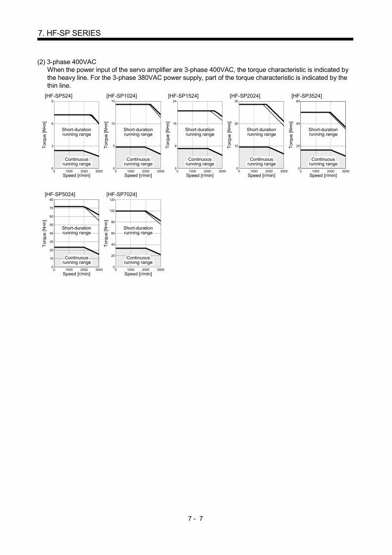
7 - 7
7. HF-SP SERIES
(2) 3-phase 400VAC
When the power input of the servo amplifier are 3-phase 400VAC, the torque characteristic is indicated by the heavy line. For the 3-phase 380VAC power supply, part of the torque characteristic is indicated by the thin line.
[HF-SP524]
1000 2000 300000
6
9
3
Speed [r/min]
Continuousrunning range
Short-durationrunning range
Tor
que
[N•m
]
[HF-SP1024]
1000 2000 300000
10
15
5
Speed [r/min]
Continuousrunning range
Short-durationrunning range
Tor
que
[N•m
]
[HF-SP1524]
1000 2000 300000
16
24
8
Speed [r/min]
Continuousrunning range
Short-durationrunning range
Tor
que
[N•m
]
[HF-SP2024]
1000 2000 300000
20
30
10
Speed [r/min]
Continuousrunning range
Short-durationrunning range
Tor
que
[N•m
]
[HF-SP3524]
1000 2000 300000
40
60
20
Speed [r/min]
Continuousrunning range
Short-durationrunning range
Tor
que
[N•m
]
[HF-SP5024]
1000 2000 300000
60
80
40
70
50
30
20
10
Speed [r/min]
Continuousrunning range
Short-durationrunning range
Tor
que
[N•m
]
[HF-SP7024]
1000 2000 300000
80
120
40
100
60
20
Speed [r/min]
Continuousrunning range
Short-durationrunning range
Tor
que
[N•m
]
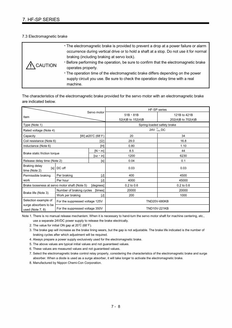
7 - 8
7. HF-SP SERIES
7.3 Electromagnetic brake
CAUTION
The electromagnetic brake is provided to prevent a drop at a power failure or alarm
occurrence during vertical drive or to hold a shaft at a stop. Do not use it for normal
braking (including braking at servo lock).
Before performing the operation, be sure to confirm that the electromagnetic brake
operates properly.
The operation time of the electromagnetic brake differs depending on the power
supply circuit you use. Be sure to check the operation delay time with a real
machine.
The characteristics of the electromagnetic brake provided for the servo motor with an electromagnetic brake
are indicated below.
Servo motor
Item
HF-SP series
51B 81B
52(4)B to 152(4)B
121B to 421B
202(4)B to 702(4)B
Type (Note 1) Spring-loaded safety brake
Rated voltage (Note 4) 24V 010% DC
Capacity [W] at20 (68 ) 20 34
Coil resistance (Note 6) [ ] 29.0 16.8
Inductance (Note 6) [H] 0.80 1.10
Brake static friction torque [N m] 8.5 44
[oz in] 1200 6230
Release delay time (Note 2) [s] 0.04 0.1
Braking delay
time (Note 2) [s] DC off 0.03 0.03
Permissible braking
work
Per braking [J] 400 4500
Per hour [J] 4000 45000
Brake looseness at servo motor shaft (Note 5) [degrees] 0.2 to 0.6 0.2 to 0.6
Brake life (Note 3) Number of braking cycles [times] 20000 20000
Work per braking [J] 200 1000
Selection example of
surge absorbers to be
used (Note 7, 8)
For the suppressed voltage 125V TND20V-680KB
For the suppressed voltage 350V TND10V-221KB
Note 1. There is no manual release mechanism. When it is necessary to hand-turn the servo motor shaft for machine centering, etc.,
use a separate 24VDC power supply to release the brake electrically.
2. The value for initial ON gap at 20 (68 ).
3. The brake gap will increase as the brake lining wears, but the gap is not adjustable. The brake life indicated is the number of
braking cycles after which adjustment will be required.
4. Always prepare a power supply exclusively used for the electromagnetic brake.
5. The above values are typical initial values and not guaranteed values.
6. These values are measured values and not guaranteed values.
7. Select the electromagnetic brake control relay properly, considering the characteristics of the electromagnetic brake and surge
absorber. When a diode is used as a surge absorber, it will take longer to activate the electromagnetic brake.
8. Manufactured by Nippon Chemi-Con Corporation.

7 - 9
7. HF-SP SERIES
7.4 Servo motors with special shafts
The servo motors with special shafts indicated by the symbol (K) in the table is available. K is the symbols
attached to the servo motor model names.
Servo motor Shaft shape
Keyway shaft (without key)
HF-SP51(B) to 301(B)
HF-SP52(4)(B) to
702(4)(B)
K
QL
A
A
QK
Q
R
W S
U
r Y
Section A-A
[Unit: mm]
Servo motor
Variable dimensions Y
S R Q W QK QL U r
HF-SP51(B)K 81(B)K
HF-SP52(4)(B)K to
152(4)(B)K
24h6 55 50 800.036 36 5 4 0.2
0 4 M8 Depth
20
HF-SP121(B)K to
421(B)K
HF-SP202(4)(B)K to
702(4)(B)K
35 0.0100 79 75 10 0
0.036 55 5 5 0.20 5
M8 Depth
20
Keyway shaft (without key)
7.5 Servo motor with oil seal
HP-SP series has the servo motor with oil seal (HF-SP J) Model construction of the servo motor refer to section 7.1. Mounting the oil seal is regardless to outline dimensions. Install the servo motor horizontally, and set the oil level in the gear box to be lower than the oil seal lip always.
GearShaft
Servo motor
Oil seal
Height above oil level h
Lip
Servo motor Height above oil level h [mm]
HF-SP81(B)J 20
HF-SP121(B)J to 301(B)J 25
HF-SP52(4)(B)J to
152(4)(B)J 20
HF-SP202(4)(B)J to
702(4)(B)J 25
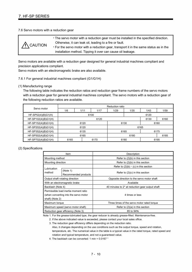
7 - 10
7. HF-SP SERIES
7.6 Servo motors with a reduction gear
CAUTION
The servo motor with a reduction gear must be installed in the specified direction.
Otherwise, it can leak oil, leading to a fire or fault.
For the servo motor with a reduction gear, transport it in the same status as in the
installation method. Tipping it over can cause oil leakage.
Servo motors are available with a reduction gear designed for general industrial machines compliant and
precision applications compliant.
Servo motors with an electromagnetic brake are also available. 7.6.1 For general industrial machines compliant (G1/G1H)
(1) Manufacturing range
The following table indicates the reduction ratios and reduction gear frame numbers of the servo motors
with a reduction gear for general industrial machines compliant. The servo motors with a reduction gear of
the following reduction ratios are available.
Servo motor Reduction ratio
1/6 1/11 1/17 1/29 1/35 1/43 1/59
HF-SP52(4)(B)G1(H) 6100 6120
HF-SP102(4)(B)G1(H) 6120 6130 6160
HF-SP152(4)(B)G1(H) 6120 6130 6160
HF-SP202(4)(B)G1(H) 6120 6165
HF-SP352(4)(B)G1(H) 6135 6165 6175
HF-SP502(4)(B)G1(H) 6165 6180 6185
HF-SP702(4)(B)G1(H) 6165 6170 6180 6195
(2) Specifications Item Description
Mounting method Refer to (2)(b) in this section
Mounting direction Refer to (2)(b) in this section
Lubrication
method
Refer to (2)(b) (c) in this section
(Note 1)
Recommended products Refer to (2)(c) in this section
Output shaft rotating direction Opposite direction to the servo motor shaft
With an electromagnetic brake Available
Backlash (Note 4) 40 minutes to 2* at reduction gear output shaft
Permissible load inertia moment ratio
(when converting into the servo motor
shaft) (Note 2)
4 times or less
Maximum torque Three times of the servo motor rated torque
Maximum speed (servo motor shaft) Refer to (2)(a) in this section
Reduction gear efficiency (Note 3) 85 to 94
Note 1. For the grease-lubricated type, the gear reducer is already grease-filled. Maintenance-free.
2. If the above indicated value is exceeded, please contact your local sales office.
3. The reduction gear efficiency differs depending on the reduction ratio.
Also, it changes depending on the use conditions such as the output torque, speed and rotation,
temperature, etc. The numerical value in the table is a typical value in the rated torque, rated speed and
rotation and typical temperature, and not a guaranteed value.
4. The backlash can be converted: 1 min = 0.0167 °
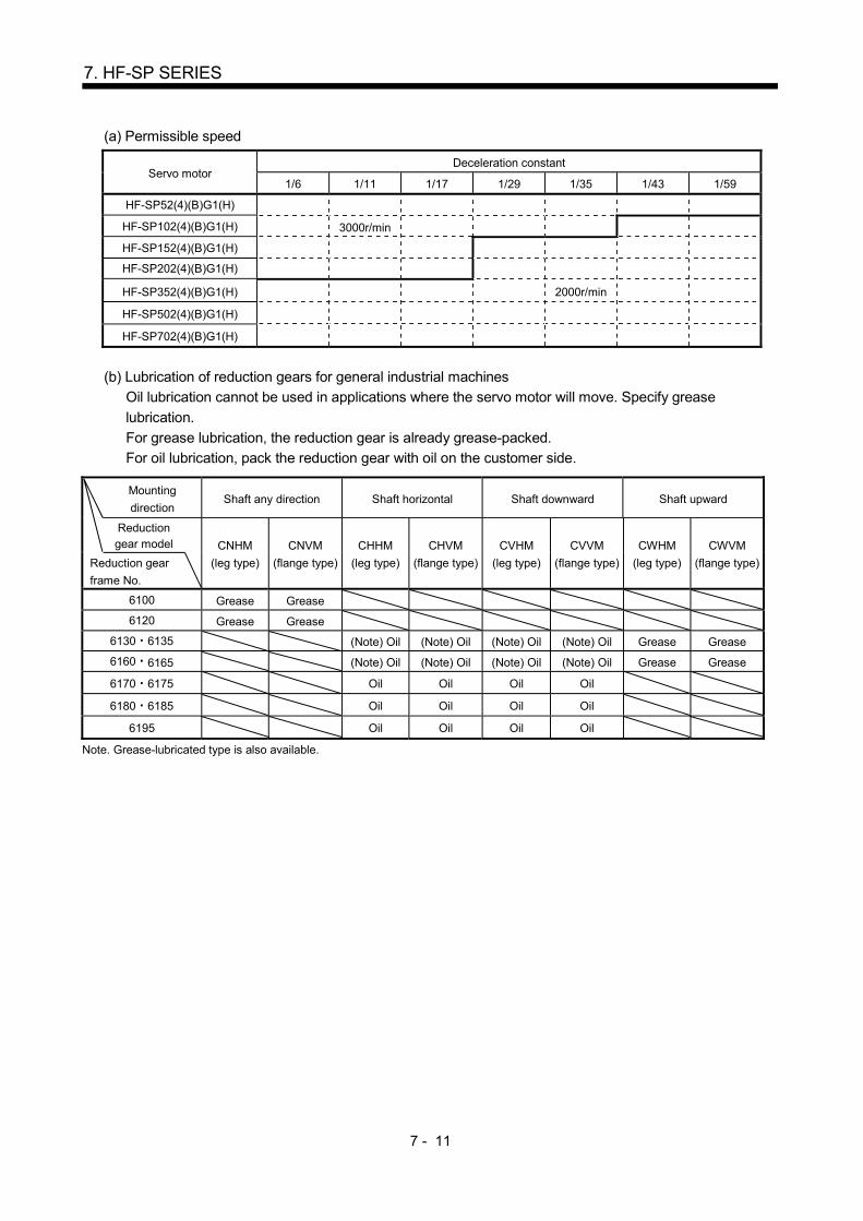
7 - 11
7. HF-SP SERIES
(a) Permissible speed
Servo motor Deceleration constant
1/6 1/11 1/17 1/29 1/35 1/43 1/59
HF-SP52(4)(B)G1(H)
HF-SP102(4)(B)G1(H) 3000r/min
HF-SP152(4)(B)G1(H)
HF-SP202(4)(B)G1(H)
HF-SP352(4)(B)G1(H) 2000r/min
HF-SP502(4)(B)G1(H)
HF-SP702(4)(B)G1(H)
(b) Lubrication of reduction gears for general industrial machines
Oil lubrication cannot be used in applications where the servo motor will move. Specify grease
lubrication.
For grease lubrication, the reduction gear is already grease-packed.
For oil lubrication, pack the reduction gear with oil on the customer side.
Mounting
direction Shaft any direction Shaft horizontal Shaft downward Shaft upward
Reduction gear model
CNHM
(leg type)
CNVM
(flange type)
CHHM
(leg type)
CHVM
(flange type)
CVHM
(leg type)
CVVM
(flange type)
CWHM
(leg type)
CWVM
(flange type) Reduction gear
frame No.
6100 Grease Grease
6120 Grease Grease
6130 6135 (Note) Oil (Note) Oil (Note) Oil (Note) Oil Grease Grease
6160 6165 (Note) Oil (Note) Oil (Note) Oil (Note) Oil Grease Grease
6170 6175 Oil Oil Oil Oil
6180 6185 Oil Oil Oil Oil
6195 Oil Oil Oil Oil
Note. Grease-lubricated type is also available.
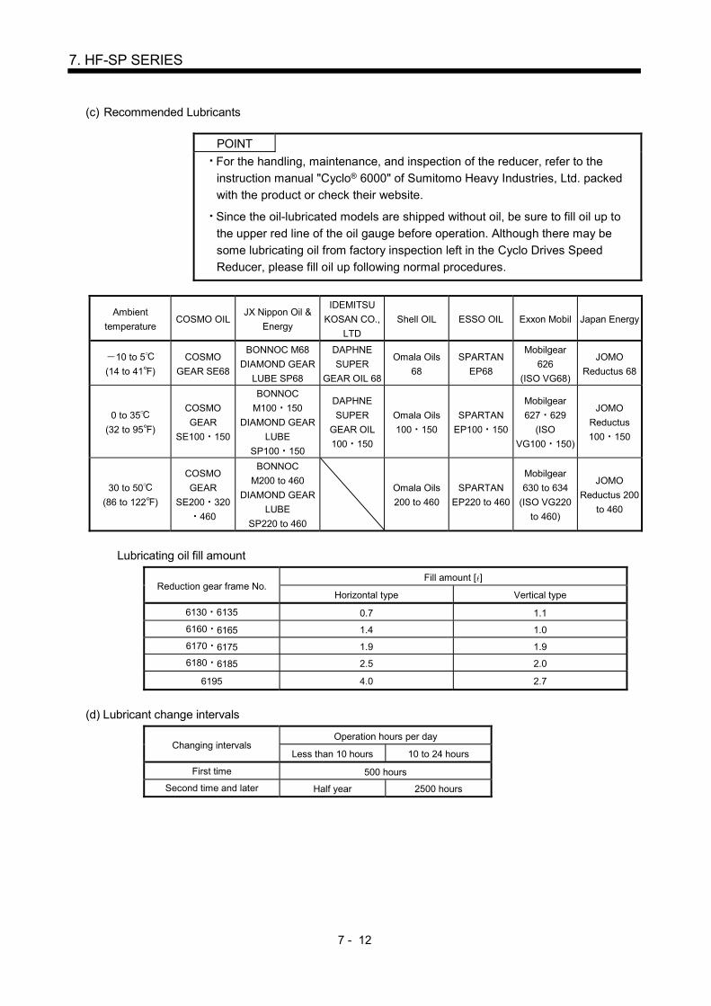
7 - 12
7. HF-SP SERIES
(c) Recommended Lubricants
POINT
For the handling, maintenance, and inspection of the reducer, refer to the
instruction manual "Cyclo® 6000" of Sumitomo Heavy Industries, Ltd. packed
with the product or check their website.
Since the oil-lubricated models are shipped without oil, be sure to fill oil up to
the upper red line of the oil gauge before operation. Although there may be
some lubricating oil from factory inspection left in the Cyclo Drives Speed
Reducer, please fill oil up following normal procedures.
Ambient
temperature COSMO OIL
JX Nippon Oil &
Energy
IDEMITSU
KOSAN CO.,
LTD
Shell OIL ESSO OIL Exxon Mobil Japan Energy
10 to 5
(14 to 41 )
COSMO
GEAR SE68
BONNOC M68
DIAMOND GEAR
LUBE SP68
DAPHNE
SUPER
GEAR OIL 68
Omala Oils
68
SPARTAN
EP68
Mobilgear
626
(ISO VG68)
JOMO
Reductus 68
0 to 35
(32 to 95 )
COSMO
GEAR
SE100 150
BONNOC
M100 150
DIAMOND GEAR
LUBE
SP100 150
DAPHNE
SUPER
GEAR OIL
100 150
Omala Oils
100 150
SPARTAN
EP100 150
Mobilgear
627 629
(ISO
VG100 150)
JOMO
Reductus
100 150
30 to 50
(86 to 122 )
COSMO
GEAR
SE200 320
460
BONNOC
M200 to 460
DIAMOND GEAR
LUBE
SP220 to 460
Omala Oils
200 to 460
SPARTAN
EP220 to 460
Mobilgear
630 to 634
(ISO VG220
to 460)
JOMO
Reductus 200
to 460
Lubricating oil fill amount
Reduction gear frame No. Fill amount [ ]
Horizontal type Vertical type
6130 6135 0.7 1.1
6160 6165 1.4 1.0
6170 6175 1.9 1.9
6180 6185 2.5 2.0
6195 4.0 2.7
(d) Lubricant change intervals
Changing intervals Operation hours per day
Less than 10 hours 10 to 24 hours
First time 500 hours
Second time and later Half year 2500 hours
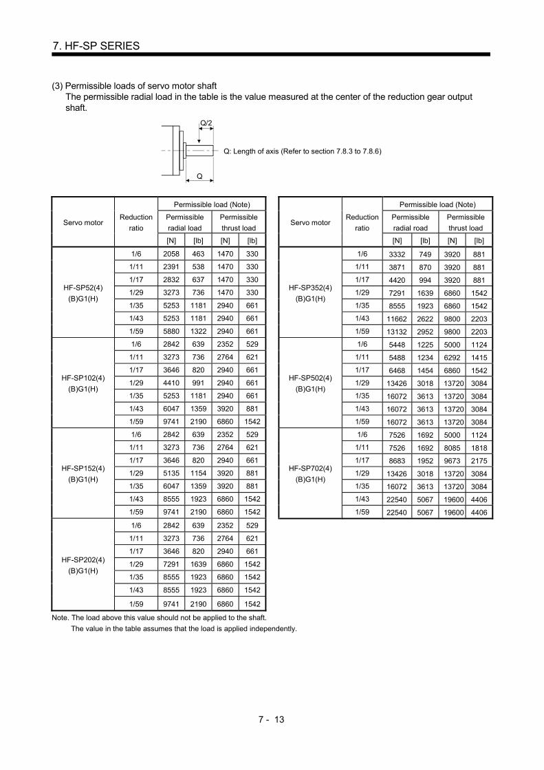
7 - 13
7. HF-SP SERIES
(3) Permissible loads of servo motor shaft The permissible radial load in the table is the value measured at the center of the reduction gear output
shaft.
Q/2
Q
Q: Length of axis (Refer to section 7.8.3 to 7.8.6)
Servo motor Reduction
ratio
Permissible load (Note)
Servo motor Reduction
ratio
Permissible load (Note)
Permissible
radial load
Permissible
thrust load
Permissible
radial road
Permissible
thrust load
[N] [lb] [N] [lb] [N] [lb] [N] [lb]
HF-SP52(4)
(B)G1(H)
1/6 2058 463 1470 330
HF-SP352(4)
(B)G1(H)
1/6 3332 749 3920 881
1/11 2391 538 1470 330 1/11 3871 870 3920 881
1/17 2832 637 1470 330 1/17 4420 994 3920 881
1/29 3273 736 1470 330 1/29 7291 1639 6860 1542
1/35 5253 1181 2940 661 1/35 8555 1923 6860 1542
1/43 5253 1181 2940 661 1/43 11662 2622 9800 2203
1/59 5880 1322 2940 661 1/59 13132 2952 9800 2203
HF-SP102(4)
(B)G1(H)
1/6 2842 639 2352 529
HF-SP502(4)
(B)G1(H)
1/6 5448 1225 5000 1124
1/11 3273 736 2764 621 1/11 5488 1234 6292 1415
1/17 3646 820 2940 661 1/17 6468 1454 6860 1542
1/29 4410 991 2940 661 1/29 13426 3018 13720 3084
1/35 5253 1181 2940 661 1/35 16072 3613 13720 3084
1/43 6047 1359 3920 881 1/43 16072 3613 13720 3084
1/59 9741 2190 6860 1542 1/59 16072 3613 13720 3084
HF-SP152(4)
(B)G1(H)
1/6 2842 639 2352 529
HF-SP702(4)
(B)G1(H)
1/6 7526 1692 5000 1124
1/11 3273 736 2764 621 1/11 7526 1692 8085 1818
1/17 3646 820 2940 661 1/17 8683 1952 9673 2175
1/29 5135 1154 3920 881 1/29 13426 3018 13720 3084
1/35 6047 1359 3920 881 1/35 16072 3613 13720 3084
1/43 8555 1923 6860 1542 1/43 22540 5067 19600 4406
1/59 9741 2190 6860 1542 1/59 22540 5067 19600 4406
HF-SP202(4)
(B)G1(H)
1/6 2842 639 2352 529
1/11 3273 736 2764 621
1/17 3646 820 2940 661
1/29 7291 1639 6860 1542
1/35 8555 1923 6860 1542
1/43 8555 1923 6860 1542
1/59 9741 2190 6860 1542
Note. The load above this value should not be applied to the shaft.
The value in the table assumes that the load is applied independently.
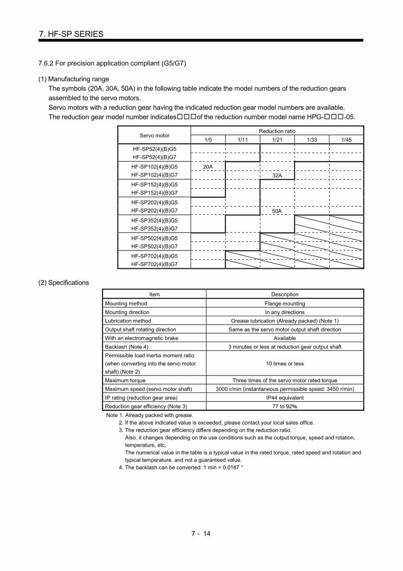
7 - 14
7. HF-SP SERIES
7.6.2 For precision application compliant (G5/G7)
(1) Manufacturing range
The symbols (20A, 30A, 50A) in the following table indicate the model numbers of the reduction gears
assembled to the servo motors.
Servo motors with a reduction gear having the indicated reduction gear model numbers are available.
The reduction gear model number indicates of the reduction number model name HPG- -05.
Servo motor Reduction ratio
1/5 1/11 1/21 1/33 1/45
HF-SP52(4)(B)G5
HF-SP52(4)(B)G7
HF-SP102(4)(B)G5
HF-SP102(4)(B)G7
20A
32A
HF-SP152(4)(B)G5
HF-SP152(4)(B)G7
HF-SP202(4)(B)G5
HF-SP202(4)(B)G7
50A
HF-SP352(4)(B)G5
HF-SP352(4)(B)G7
HF-SP502(4)(B)G5
HF-SP502(4)(B)G7
HF-SP702(4)(B)G5
HF-SP702(4)(B)G7
(2) Specifications Item Description
Mounting method Flange mounting
Mounting direction In any directions
Lubrication method Grease lubrication (Already packed) (Note 1)
Output shaft rotating direction Same as the servo motor output shaft direction
With an electromagnetic brake Available
Backlash (Note 4) 3 minutes or less at reduction gear output shaft
Permissible load inertia moment ratio
(when converting into the servo motor
shaft) (Note 2)
10 times or less
Maximum torque Three times of the servo motor rated torque
Maximum speed (servo motor shaft) 3000 r/min (instantaneous permissible speed: 3450 r/min)
IP rating (reduction gear area) IP44 equivalent
Reduction gear efficiency (Note 3) 77 to 92
Note 1. Already packed with grease. 2. If the above indicated value is exceeded, please contact your local sales office. 3. The reduction gear efficiency differs depending on the reduction ratio.
Also, it changes depending on the use conditions such as the output torque, speed and rotation, temperature, etc. The numerical value in the table is a typical value in the rated torque, rated speed and rotation and typical temperature, and not a guaranteed value.
4. The backlash can be converted: 1 min = 0.0167 °

7 - 15
7. HF-SP SERIES
(3) Permissible loads of servo motor shaft
The radial load point of a precision reduction gear is as shown below.
L
L: Distance between reduction gear end face and load center
Q/2
Q
Q: Length of axis (Refer to section 7.8.9, 7.8.10)
Flange-mounting flange output type for precision application compliant (G5)
Flange-mounting shaft output type for precision application compliant (G7)
Servo motor Reduction ratio Radial load point L
[mm]
Permissible load (Note)
Permissible radial
load
Permissible thrust
load
[N] [lb] [N] [lb]
HF-SP52(4)(B)G5
HF-SP52(4)(B)G7
1/5 32 416 93.5 1465 329
1/11 32 527 118 1856 417
1/21 57 1094 246 4359 980
1/33 57 1252 281 4992 1120
1/45 57 1374 309 5478 1230
HF-SP102(4)(B)G5
HF-SP102(4)(B)G7
1/5 32 416 93.5 1465 329
1/11 57 901 203 3590 807
1/21 57 1094 246 4359 980
1/33 62 2929 658 10130 2280
1/45 62 3215 723 11117 2500
HF-SP152(4)(B)G5
HF-SP152(4)(B)G7
1/5 32 416 93.5 1465 329
1/11 57 901 203 3590 807
1/21 62 2558 575 8845 1990
1/33 62 2929 658 10130 2280
1/45 62 3215 723 11117 2500
HF-SP202(4)(B)G5
HF-SP202(4)(B)G7
1/5 57 711 160 2834 637
1/11 57 901 203 3590 807
1/21 62 2558 575 8845 1990
1/33 62 2929 658 10130 2280
1/45 62 3215 723 11117 2500
HF-SP352(4)(B)G5
HF-SP352(4)(B)G7
1/5 57 711 160 2834 637
1/11 62 2107 474 7285 1640
1/21 62 2558 575 8845 1990
HF-SP502(4)(B)G5
HF-SP502(4)(B)G7
1/5 62 1663 374 5751 1290
1/11 62 2107 474 7285 1640
HF-SP702(4)(B)G5
HF-SP702(4)(B)G7 1/5 62 1663 374 5751 1290
Note. The load above this value should not be applied to the shaft.
The value in the table assumes that the load is applied independently.

7 - 16
7. HF-SP SERIES
(4) Special shaft servo motors
Servo motors with special shafts having keyway (with single pointed keys) are available for the flange-
mounting shaft output type for precision applications compliant (G7).
[Unit: mm]
Servo motor Reduction gear
model number Q S W T QK U Y
HF-SP (B)G7K
20A 42 25h7 8 7 36 4 M6
Depth 12
32A 82 40h7 12 8 70 5 M10
Depth 20 50A 82 50h7 14 9 70 5.5
UApprox. Q
QK
W
T
S
Y
7.7 Wiring option
Connecter sets to use in power supply connector or brake connector are available as option.
For details of each connector set, cable and connector set to use in wiring to encoder, refer to the Servo
Amplifier Instruction Manual for using.
Make sure to use the following power supply connector set for conforming to the EN compliant.
Servo motor (Note) Power supply
connector set Brake connector set
HF-SP
HF-SP51 81
MR-PWCNS4
MR-BKCNS1
Configuration products
Straight plug : CM10-SP2S-L(D6)
Socket contact : CM10-#22SC(S2)(D8)-100
(DDK)
HF-SP52 to 152
HF-SP524 to 1524
HF-SP121 to 301
MR-PWCNS5 HF-SP202 to 502
HF-SP2024 to 5024
HF-SP421
MR-PWCNS3 HF-SP702
HF-SP7024
Note. The configuration products for power supply connector set are as shown below. (all manufactured by
DDK)
MR-PWCNS4 (Plug: CE05-6A18-10SD-D-BSS Cable clamp: CE3057-10A-1-D
MR-PWCNS5 (Plug: CE05-6A22-22SD-D-BSS Cable clamp: CE3057-12A-1-D
MR-PWCNS3 (Plug: CE05-6A32-17SD-D-BSS Cable clamp: CE3057-20A-1-D

7 - 17
7. HF-SP SERIES
7.8 Outline dimension drawings
The dimensions without tolerances are reference dimensions.
The outer frame of the reduction gear is a material surface such as casting. Its actual dimensions may be 1 to
3mm larger than the drawing dimensions. Design the machine side with allowances.
Inertia moment on the table is the value calculated by converting the total value of inertia moment for servo
motor, electromagnetic brake and decelerator with servo motor shaft. 7.8.1 Standard (without an electromagnetic brake, without a reduction gear)
Model Output
[kW]
Inertia moment
J [ 10-4kg m2]
(WK2 [oz in2])
Mass
[kg] ([lb])
HF-SP52 0.5 6.1 (33.4) 4.8 (10.6)
HF-SP524
[Unit: mm]
(Earth)
57.8
13
13055
312
5038.2
58
13.5
145
165
Power supplyconnector
MS3102A18-10P
Motor plate(Opposite side)
Encoder connector
CM10-R10P
Caution plateCaution plate
4- 9 mounting holeUse hexagon sockethead cap screw
Power supply connector layout
B
C
W
V U
A
D
Motor plate
45
118.5
Cautionplate
Motor flange direction
20.9
BC26160*
Bottom
Top
Bottom
Top
Bottom
Top
Bottom
TopBottom
Top
TUV plate
Model Output
[kW]
Inertia moment
J [ 10-4kg m2]
(WK2 [oz in2])
Mass
[kg] ([lb])
HF-SP51 0.5
11.9 (65.1) 6.5 (14.3)
HF-SP102 1.0
HF-SP1024 6.7 (14.8)
[Unit: mm]
(Earth)
79.8
13
13055
312
5038.2
58
13.5
145
165
Power supply
connectorMS3102A18-10P
Encoder connectorCM10-R10P
Caution plate
V UPower supply connector layout
B
W
C
A
D
45
140.5
Cautionplate
Motor flange direction
Caution plate
20.9
BC26161*
Motor plate
Bottom
Top
Bottom
Top Bottom
Top
Bottom
Top
Motor plate(Opposite side)
4- 9 mounting holeUse hexagon socket
head cap screw
Bottom
Top
TUV plate
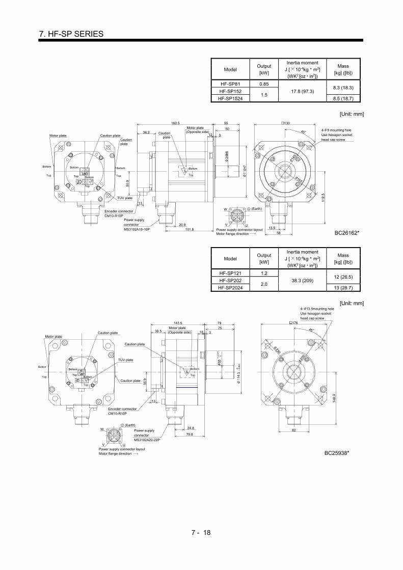
7 - 18
7. HF-SP SERIES
Model Output
[kW]
Inertia moment
J [ 10-4kg m2]
(WK2 [oz in2])
Mass
[kg] ([lb])
HF-SP81 0.85
17.8 (97.3) 8.3 (18.3)
HF-SP152 1.5
HF-SP1524 8.5 (18.7)
[Unit: mm]
(Earth)
101.8
13
13055
312
5038.2
58
13.5
145
165
Power supplyconnector
MS3102A18-10P
Encoder connectorCM10-R10P
Caution plate
V UPower supply connector layout
B
WC
A
D
45
162.5
Motor flange direction
Cautionplate
20.9
BC26162*
Motor plateCaution
plate
Motor plate(Opposite side) 4- 9 mounting hole
Use hexagon socket
head cap screw
Bottom
Top
Bottom
Top
Bottom
Top Bottom
Top
Bottom
Top
TUV plate
Model Output
[kW]
Inertia moment
J [ 10-4kg m2]
(WK2 [oz in2])
Mass
[kg] ([lb])
HF-SP121 1.2
38.3 (209) 12 (26.5)
HF-SP202 2.0
HF-SP2024 13 (28.7)
[Unit: mm]
176
45
8224.8
79
31838.5
13
Caution plate
Caution plate
Encoder connectorCM10-R10P
Power supply
connectorMS3102A22-22P
W
C
B
V U
AD
Power supply connector layout
75
230
200
Motor flange direction
143.5
79.8
Caution plate
BC25938*
Motor plate
Bottom
Top
Bottom
TopBottom
Top
Motor plate(Opposite side)
Bottom
Top
4- 13.5mounting holeUse hexagon sockethead cap screw
(Earth)
TUV plate
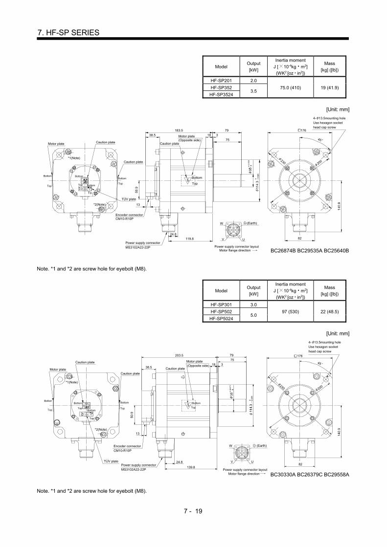
7 - 19
7. HF-SP SERIES
Model Output
[kW]
Inertia moment
J [ 10-4kg m2]
(WK2 [oz in2])
Mass
[kg] ([lb])
HF-SP201 2.0
75.0 (410) 19 (41.9) HF-SP352 3.5
HF-SP3524
[Unit: mm]
Motor plate Caution plate
Caution plate
38.5
183.5
Caution plate
Motor plate(Opposite side)
79
18 3
75
13
24.8119.8
Encoder connectorCM10-R10P
Power supply connector
MS3102A22-22P
176
200
230
82
W
C
B
V U
AD
(Earth)
4- 13.5mounting holeUse hexagon sockethead cap screw
Power supply connector layoutMotor flange direction
45
TUV plate
Top
Bottom Bottom
TopTop
Bottom
To
BottomTop
Bottom
*2(Note)
*1(Note)
BC26874B BC29535A BC25640B
Note. *1 and *2 are screw hole for eyebolt (M8).
Model Output
[kW]
Inertia moment
J [ 10-4kg m2]
(WK2 [oz in2])
Mass
[kg] ([lb])
HF-SP301 3.0
97 (530) 22 (48.5) HF-SP502 5.0
HF-SP5024
[Unit: mm]
82
*1(Note)
*2(Note)
75
3
79
18
13
38.5
24.8
203.5
139.8
45
BC30330A BC26379C BC29558A
(Earth)
176
Caution plate
Encoder connectorCM10-R10P
W
V U
Power supply connector layoutMotor flange direction
Caution plate
Power supply connectorMS3102A22-22P
230 200
Caution plateMotor plate
Bottom
Top
Bottom
Top
Bottom
TopBottom
Top
Motor plate(Opposite side)
4- 13.5mounting holeUse hexagon sockethead cap screw
Bottom
Top
AB
C D
TUV plate
Note. *1 and *2 are screw hole for eyebolt (M8).

7 - 20
7. HF-SP SERIES
Model Output
[kW]
Inertia moment
J [ 10-4kg m2]
(WK2 [oz in2])
Mass
[kg] ([lb])
HF-SP421 4.2
154 (842) 32 (70.6) HF-SP702 7.0
HF-SP7024
[Unit: mm]
(Earth)
Encoder connectorCM10-R10P
Caution plate
176
200230
75
318
79
Caution plate
(Note)
(Note)
(Note)
(Note)
32
191.8
W
V U
C
B
D
A
82
45
13
Caution plate
263.5
38.5
Power supply connectorMS3102A32-17P
Power supply connector layoutMotor flange direction BC26380A
(Note)
*2
(Note)
*1
*2
*1
*4 *4
(Note)*3
(Note)
*3
Motor plate
Bottom
Top
Bottom
Top
Bottom
Top
Motor plate(Opposite side)
Bottom
Top
4- 13.5 mounting hole
Use hexagon socket
head cap screw
BC29559*
Note. *1, *2, *3 and *4 are screw hole for eyebolt (M8). 7.8.2 With an electromagnetic brake
Model Output
[kW]
Brake static friction
torque [N m]
([oz in])
Inertia moment
J [ 10-4kg m2]
(WK2 [oz in2])
Mass
[kg] ([lb])
HF-SP52B 0.5 8.5 (1200) 8.3 (45.4) 6.7 (14.8)
HF-SP524B
[Unit: mm]
(Earth)
130
165
145
13.558
12 3
153
43.5
55
50
UPower supply connector layout
57.8Power supply connectorMS3102A18-10P
13
Encoder connectorCM10-R10P
Caution plate
59
Brake connectorCM10-R2P
AB
C D
V
W
Brake connector layoutBrake
29
45
20.9
Motor flange direction Motor flange direction
Cautionplate
Caution plate
BC26163*
Bottom
Top
Bottom
TopBottom
Top
Bottom
Top
Bottom
Top
4- 9 mounting holeUse hexagon sockethead cap screw
Motor plate
Motor plate(Opposite side)
TUV plate

7 - 21
7. HF-SP SERIES
Model Output
[kW]
Brake static friction
torque [N m]
([oz in])
Inertia moment
J [ 10-4kg m2]
(WK2 [oz in2])
Mass
[kg] ([lb])
HF-SP51B 0.5
8.5 (1200) 14.0 (76.5) 8.5 (18.7)
HF-SP102B 1.0
HF-SP1024B 8.6 (19.0)
[Unit: mm]
(Earth)
130
165
145
13.5
58
12 3
175
43.5
55
50
UPower supply connector layout
79.8Power supply connector
MS3102A18-10P
13
Encoder connectorCM10-R10P
Caution plate
59
Brake connector
CM10-R2P
AB
C D
V
W
Brake connector layoutBrake
29
45
20.9
Caution plate
Motor flange direction Motor flange direction
Cautionplate
BC26164*
Bottom
Top
Bottom
TopBottom
Top
Bottom
Top
Bottom
Top
Motor plateMotor plate(Opposite side)
4- 9 mounting holeUse hexagon sockethead cap screw
TUV plate
Model Output
[kW]
Brake static friction
torque [N m]
([oz in])
Inertia moment
J [ 10-4kg m2]
(WK2 [oz in2])
Mass
[kg] ([lb])
HF-SP81B 0.85
8.5 (1200) 20.0 (109) 10.3 (22.7)
HF-SP152B 1.5
HF-SP1524B 11 (24.3)
[Unit: mm]
130
165
145
13.5
58
12 3
197
43.5
55
50
UPower supply connector layout
101.8Power supply connectorMS3102A18-10P
13
Encoder connectorCM10-R10P
Caution plate
59
Brake connectorCM10-R2P
AB
C D
V
W
Brake connector layoutBrake
29
45
20.9
Caution plate
Motor flange direction Motor flange direction
Cautionplate
BC26165*
Bottom
Top
Bottom
TopBottom
Top
Bottom
Top
Motor plate(Opposite side)
Bottom
Top
4- 9 mounting holeUse hexagon sockethead cap screw
Motor plate
(Earth)
TUV plate
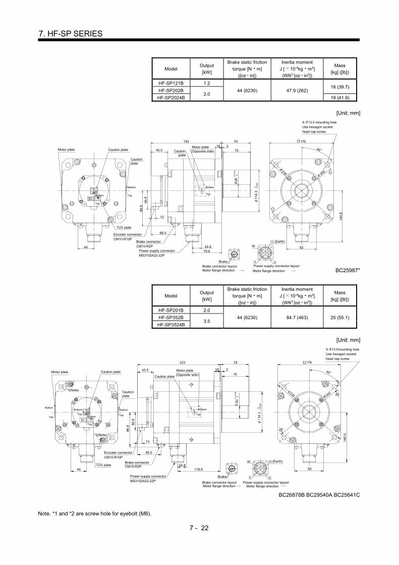
7 - 22
7. HF-SP SERIES
Model Output
[kW]
Brake static friction
torque [N m]
([oz in])
Inertia moment
J [ 10-4kg m2]
(WK2 [oz in2])
Mass
[kg] ([lb])
HF-SP121B 1.2
44 (6230) 47.9 (262) 18 (39.7)
HF-SP202B 2.0
HF-SP2024B 19 (41.9)
[Unit: mm]
(Earth)
45
8224.8
13
44
Caution plate
Encoder connectorCM10-R10P
Brake connectorCM10-R2P
Power supply connectorMS3102A22-22P
Brake connector layoutBrake
W
C
B
V U
AD
Power supply connector layout
Motor flange directionMotor flange direction
193
79.8
79
Cautionplate
Cautionplate
66.5
200230
17618
753
45.5
BC25987*
4- 13.5 mounting holeUse hexagon sockethead cap screw
Motor plate
Bottom
Top
Bottom
Top
Motor plate(Opposite side)
Bottom
Top
TUV plate
Model Output
[kW]
Brake static friction
torque [N m]
([oz in])
Inertia moment
J [ 10-4kg m2]
(WK2 [oz in2])
Mass
[kg] ([lb])
HF-SP201B 2.0
44 (6230) 84.7 (463) 25 (55.1) HF-SP352B 3.5
HF-SP3524B
[Unit: mm]
79233
45.5 18 3
75
82119.824.8
66.5
13
44
BC26878B BC29540A BC25641C
Motor flange directionBrake connector layout
Brake
45
*1(Note)
*2(Note)
Brake connectorCM10-R2P
(Earth)
176
Caution plate
Encoder connector
CM10-R10PW
V U
AB
C D
Power supply connector layoutMotor flange direction
Caution plate
Power supply connectorMS3102A22-22P
230 200Cautionplate
Motor plate
Bottom
Top
Bottom
Top Bottom
Top
Bottom
Top
Motor plate(Opposite side)
4- 13.5mounting holeUse hexagon sockethead cap screw
Bottom
Top
TUV plate
Note. *1 and *2 are screw hole for eyebolt (M8).
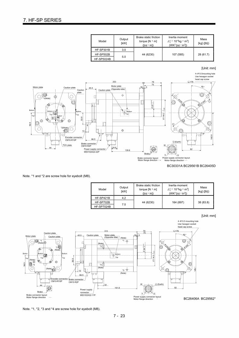
7 - 23
7. HF-SP SERIES
Model Output
[kW]
Brake static friction
torque [N m]
([oz in])
Inertia moment
J [ 10-4kg m2]
(WK2 [oz in2])
Mass
[kg] ([lb])
HF-SP301B 3.0
44 (6230) 107 (585) 28 (61.7) HF-SP502B 5.0
HF-SP5024B
[Unit: mm]
BC30331A BC29561B BC26405D
82139.824.8
79
44
18 375
13
45.5
66.5
253
45
(Earth)
176
Caution plate
Encoder connectorCM10-R10P
W
V U
AB
C D
Power supply connector layoutMotor flange direction
Caution plate
Power supply connector
MS3102A22-22P
230 200
Cautionplate
Motor plate
Bottom
Top
Bottom
Top
Bottom
Top Bottom
Top
Motor plate
(Opposite side)
4- 13.5mounting holeUse hexagon sockethead cap screw
Bottom
Top
Brake
Motor flange directionBrake connector layout
Brake connectorCM10-R2P
*1(Note)
*2(Note)
TUV plate
Note. *1 and *2 are screw hole for eyebolt (M8).
Model Output
[kW]
Brake static friction
torque [N m]
([oz in])
Inertia moment
J [ 10-4kg m2]
(WK2 [oz in2])
Mass
[kg] ([lb])
HF-SP421B 4.2
44 (6230) 164 (897) 38 (83.8) HF-SP702B 7.0
HF-SP7024B
[Unit: mm]
176
200230
75318
79
44 32
191.8
V
W
U
ADC
B
45
82
13
45.5
313
66.5
(Note)
(Note)
(Note)
(Note)
Caution plate
CM10-R10PEncoder connector Brake connector
CM10-R2P
Motor flange directionBrake connector layout
Brake
Caution plate
Power supplyconnectorMS3102A32-17P
Power supply connector layoutMotor flange direction
Caution plate
BC26406A
*1
*2
(Note)
*2
(Note)*1
*4*3
*3(Note)
*4(Note)
Motor plate
Bottom
Top
Bottom
Top
Bottom
Top
Motor plate(Opposite side)
Bottom
Top
4- 13.5 mounting holeUse hexagon sockethead cap screw
BC29562*
(Earth)
Note. *1, *2, *3 and *4 are screw hole for eyebolt (M8).

7 - 24
7. HF-SP SERIES
7.8.3 For general industrial machine with a reduction gear (without an electromagnetic brake)
Model Output
[kW]
Reduction gear
frame number
Reduction ratio
(Actual reduction ratio)
Inertia moment
J [ 10-4kg m2] (WK2 [oz in2])
Mass
[kg] ([lb])
HF-SP52G1
HF-SP524G1 0.5 6100
1/6 7.10 (38.8)
18.3 (40.3) 1/11 6.70 (36.6)
1/17 6.60 (36.1)
1/29 6.50 (35.5)
[Unit: mm]
Motor flange direction
V U
Power supply connector layout
B
W
CA
D
TUV plate
(Side view of motor only)
50.9
112.5
130
13
60.7
275 48
108
35
32
134A
A
Section AA
28h6
8Encoder connectorCM10-R10P
Power supply connectorMS3102A18-10P
Rotation direction
For forward rotation command
For reverse rotation command
M8 screwDepth 20
BC26685*
20.9
Motor plate
Caution plate
Caution plate
Caution plateMotor plate
4- 119 3 4538.2
(Earth)
Top
TopBottom
Bottom
TopBottom
Model Output
[kW]
Reduction gear
frame number
Reduction ratio
(Actual reduction ratio)
Inertia moment
J [ 10-4kg m2] (WK2 [oz in2])
Mass
[kg] ([lb])
HF-SP52G1
HF-SP524G1 0.5 6120
1/35 7.30 (39.9)
26.8 (59.1) 1/43
1/59 7.20 (39.4)
[Unit: mm]
Motor flange direction
V U
Power supply connector layout
B
W
CAD
TUV plate
(Side view of motor only)
50.9
112.5
130
13
60.7
Section AA
Encoder connectorCM10-R10P
Power supply connector
MS3102A18-10P
20.9
Motor plate
Caution plate
Caution plate
Caution plate
Motor plate
180
55
117
69
38h6
10
For reverse rotation command
For forward rotation command
Rotation direction
306- 11
268
50
A
A
M8 screwDepth 20
13 4
BC26491*
(Earth)
TopBottom
TopBottom
TopBottom
38.2
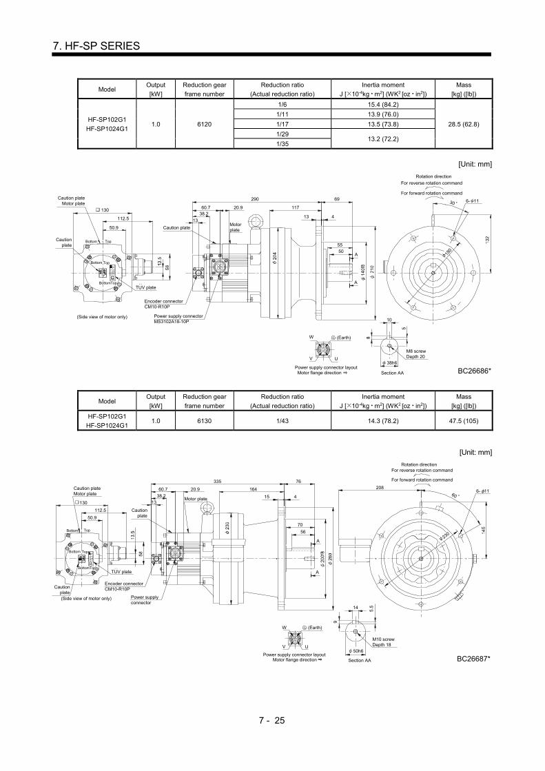
7 - 25
7. HF-SP SERIES
Model Output
[kW]
Reduction gear
frame number
Reduction ratio
(Actual reduction ratio)
Inertia moment
J [ 10-4kg m2] (WK2 [oz in2])
Mass
[kg] ([lb])
HF-SP102G1
HF-SP1024G1 1.0 6120
1/6 15.4 (84.2)
28.5 (62.8)
1/11 13.9 (76.0)
1/17 13.5 (73.8)
1/29 13.2 (72.2)
1/35
[Unit: mm]
Motor flange direction
V U
Power supply connector layout
B
W
CAD
TUV plate
(Side view of motor only)
50.9
112.5
130
13
60.7
290
Section AA
Encoder connectorCM10-R10P
Power supply connectorMS3102A18-10P
Rotation direction
For forward rotation command
For reverse rotation command
6- 11
180
38h6
10
5055
117
69
A
A
3020.9
MotorplateCaution plate
M8 screwDepth 20
BC26686*
Caution plateMotor plate
Cautionplate
13 438.2
(Earth)
TopBottom
TopBottom
BottomTop
Model Output
[kW]
Reduction gear
frame number
Reduction ratio
(Actual reduction ratio)
Inertia moment
J [ 10-4kg m2] (WK2 [oz in2])
Mass
[kg] ([lb])
HF-SP102G1
HF-SP1024G1 1.0 6130 1/43 14.3 (78.2) 47.5 (105)
[Unit: mm]
Motor flange direction
V U
Power supply connector layout
B
W
CAD
TUV plate
(Side view of motor only)
50.9
112.5
130 13
60.7
335
Section AA
Encoder connectorCM10-R10P
Power supplyconnector
Rotation direction
For forward rotation command
For reverse rotation command
A
A
56
70
164
76
14
50h6
M10 screwDepth 18
BC26687*
20.9
Motor plate
Cautionplate
Cautionplate
Caution plateMotor plate
15 4
230
20860
6- 11
(Earth)
TopBottom
TopBottom
BottomTop
38.2

7 - 26
7. HF-SP SERIES
Model Output
[kW]
Reduction gear
frame number
Reduction ratio
(Actual reduction ratio)
Inertia moment
J [ 10-4kg m2] (WK2 [oz in2])
Mass
[kg] ([lb])
HF-SP102G1
HF-SP1024G1 1.0 6160 1/59 20.3 (111) 82.5 (182)
[Unit: mm]
Motor flange direction
V U
Power supply connector layout
B
W
CAD
Section AA
For reverse rotation command
For forward rotation command
Rotation direction
Power supply connectorMS3102A18-10P
Encoder connectorCM10-R10P
393
60.7
13
130112.5
50.9
(Side view of motor only)
TUV plate
219
89
31080
18
60h6
M10 screwDepth 18
BC26688*
6- 1160
A
A
Cautionplate
Motorplate
20.9
Caution plateMotor plate
Cautionplate
20 4
15
228
175
90
(Earth)
Bottom Top
Bottom
Bottom Top
Top
38.2
Model Output
[kW]
Reduction gear
frame number
Reduction ratio
(Actual reduction ratio)
Inertia moment
J [ 10-4kg m2] (WK2 [oz in2])
Mass
[kg] ([lb])
HF-SP152G1
HF-SP1524G1 1.5 6120
1/6 21.3 (116)
30.3 (66.8) 1/11 19.8 (108)
1/17 19.4 (106)
[Unit: mm]
Motor flange direction
V U
Power supply connector layout
B
W
CAD
(Side view of motor only)
13
60.7
312
Encoder connectorCM10-R10P
Power supply connectorMS3102A18-10P
Rotation direction
For forward rotation command
For reverse rotation command
69
117
55
50
180
6- 11
A
10
38h6
Section AA
ATUV plate
50.9
112.5
13020.9 30
M8 screwDepth 20
BC26689*
Motor plateCaution plate
Cautionplate
Caution plateMotor plate
13 4
(Earth)
Top
Top
Bottom
Bottom
TopBottom
38.2

7 - 27
7. HF-SP SERIES
Model Output
[kW]
Reduction gear
frame number
Reduction ratio
(Actual reduction ratio)
Inertia moment
J [ 10-4kg m2] (WK2 [oz in2])
Mass
[kg] ([lb])
HF-SP152G1
HF-SP1524G1 1.5 6130
1/29 20.4 (112) 49.3 (109)
1/35
[Unit: mm]
Motor flange direction
V U
Power supply connector layout
B
W
CAD
130
112.5
50.9
TUV plate
For reverse rotation command
For forward rotation command
Rotation direction
Power supply connectorMS3102A18-10P
Encoder connectorCM10-R10P
357
60.7
13
(Side view of motor only)
164
76
70
A
A
56
14
50h6
M10 screwDepth 18
BC26690*Section AA
20.9
MotorplateCaution
plate
Cautionplate
Caution plateMotor plate
15 4
230
2086- 1160
(Earth)
Bottom Top
Bottom
Bottom Top
Top
38.2
Model Output
[kW]
Reduction gear
frame number
Reduction ratio
(Actual reduction ratio)
Inertia moment
J [ 10-4kg m2] (WK2 [oz in2])
Mass
[kg] ([lb])
HF-SP152G1
HF-SP1524G1 1.5 6160
1/43 26.3 (144) 84.3 (186)
1/59 26.2 (143)
[Unit: mm]
Section AA
(Side view of motor only)
13
60.7
415
Encoder connectorCM10-R10P
Power supply connectorMS3102A18-10P
Rotation direction
For forward rotation command
For reverse rotation command
TUV plate
50.9
112.5130
DA
C
W
B
Power supply connector layout
UV
Motor flange direction
6- 1160
310
219
89
18
60h6
M10 screwDepth 18
BC26691*
20.9
Motorplate
Cautionplate
Caution plateMotor plate
Cautionplate
20 4
228
15
175
9090
A
A80
Bottom
TopBottom
38.2
Top
BottomTop
(Earth)

7 - 28
7. HF-SP SERIES
Model Output
[kW]
Reduction gear
frame number
Reduction ratio
(Actual reduction ratio)
Inertia moment
J [ 10-4kg m2] (WK2 [oz in2])
Mass
[kg] ([lb])
HF-SP202G1
HF-SP2024G1 2.0 6120
1/6 42.1 (230)
34 (75.0) 1/11 40.5 (221)
1/17 40.2 (220)
[Unit: mm]
Power supply connector layoutMotor flange direction
(Side view of motor only)
CM10-R10P
Encoder connector
Cautionplate
TUV plate
MS3102A22-22P
Power supply connector
V
W
AD
BC
Motor plate
311176
140.9
50.9
Bottom
Bottom
Bottom Top
Caution plate13
117
69
A
4
A
U
6- 11
30
38h6
Section AA
10
M8 screwDepth 20
BC26714*
50
5513
Caution plateMotor plate
63.7
For reverse rotation command
For forward rotation command
Rotation direction
24.8
180
(Earth)
38.5
Top
Top
Model Output
[kW]
Reduction gear
frame number
Reduction ratio
(Actual reduction ratio)
Inertia moment
J [ 10-4kg m2] (WK2 [oz in2])
Mass
[kg] ([lb])
HF-SP202G1
HF-SP2024G1 2.0 6165
1/29 46.9 (256)
84 (185) 1/35 46.7 (255)
1/43 46.4 (254)
1/59
[Unit: mm]
15
228
Power supply connector layoutMotor flange direction
(Side view of motor only)
CM10-R10PEncoder connector
Cautionplate TUV plate
MS3102A22-22PPower supply connector
V
W
AD
BC
Motor plate176
140.9
50.9
Top
Bottom
Bottom Top
Cautionplate
U
63.7
Caution plateMotor plate
219
89
420
606- 11
408
24.8
18
60h6M10 screwDepth 18
BC26723*Section AA
Rotation direction
For forward rotation command
For reverse rotation command
310
175
A
A
90
80
(Earth)
38.5
13
Top
Bottom

7 - 29
7. HF-SP SERIES
Model Output
[kW]
Reduction gear
frame number
Reduction ratio
(Actual reduction ratio)
Inertia moment
J [ 10-4kg m2] (WK2 [oz in2])
Mass
[kg] ([lb])
HF-SP352G1
HF-SP3524G1 3.5 6135
1/6 84.4 (461)
57 (126) 1/11 80.1 (438)
1/17 78.8 (431)
[Unit: mm]
230
14
Section AA
50h6
ABC D
UV
W
Power supply connector layoutMotor flange direction
M10 screwDepth 18
BC26718*
393 76
164
15 4
70
56
MS3102A22-22PPower supply connector
A
A
63.7
Encoder connectorCM10-R10P
Rotation direction
For forward rotation command
For reverse rotation command
24.8
Caution plateMotor plate
Caution plateMotor plate
176
50.9
(Side view of motor only)
TUV plateCaution
plate
BottomTop
TopBottom
208
6- 1160140.9
38.5
13
(Earth)
TopBottom
Model Output
[kW]
Reduction gear
frame number
Reduction ratio
(Actual reduction ratio)
Inertia moment
J [ 10-4kg m2] (WK2 [oz in2])
Mass
[kg] ([lb])
HF-SP352G1
HF-SP3524G1 3.5 6165
1/29 83.9 (459) 91 (201)
1/35 83.7 (458)
[Unit: mm]
18
Section AA
60h6
ABC D
UV
W
Power supply connector layoutMotor flange direction
M10 screwDepth 18
BC26720*
448
MS3102A22-22P
Power supply connectorEncoder connectorCM10-R10P
60
A
A
20 4
21989
Motor plate
Caution plate24.863.7
15
CautionplateMotorplate
TopBottom
50.9140.9
176
TUV plateCautionplate
(Side view of motor only)
For reverse rotation command
For forward rotation command
Rotation direction17
5
6- 11
90
80
38.5
13
(Earth)
Top
TopBottom
Bottom
310

7 - 30
7. HF-SP SERIES
Model Output
[kW]
Reduction gear
frame number
Reduction ratio
(Actual reduction ratio)
Inertia moment
J [ 10-4kg m2] (WK2 [oz in2])
Mass
[kg] ([lb])
HF-SP352G1
HF-SP3524G1 3.5 6175
1/43 101.9 (557) 133 (293)
1/59 101.3 (554)
[Unit: mm]
20
Section AA
70h6
ABC D
UV
W
Power supply connector layoutMotor flange direction
M12 screwDepth 24
BC26725*
MS3102A22-22P
Power supplyconnector
63.7
Encoder connectorCM10-R10P
22.5
8- 14
258
22 5
94
80
A
A
487
Motor plate
Caution plate
24.8
Rotation direction
For forward rotation command
For reverse rotation command
Cautionplate
Motorplate
176140.9
(Side view of motor only)
TUV plateCaution
plate
Bottom Top
36090
50.9
38.5
13
(Earth)
243
BottomTop
BottomTop
Model Output
[kW]
Reduction gear
frame number
Reduction ratio
(Actual reduction ratio)
Inertia moment
J [ 10-4kg m2] (WK2 [oz in2])
Mass
[kg] ([lb])
HF-SP502G1
HF-SP5024G1 5.0 6165
1/6 121.2 (663)
95 (209) 1/11 108.9 (595)
1/17 104.8 (573)
[Unit: mm]
18 7
11
Section AA
60h6
ABC D
UV
W
Power supply connector layoutMotor flange direction
M10 screwDepth 18
BC26784B
60
A
300
181
15
228
82
Cautionplate
Motorplate
TopBottom
50.9
140.9
176
Cautionplate
(Side view of motor only)
For reverse rotation command
For forward rotation command
Rotation direction
468
63.7 24.8 219
20 4
80
90
340
270f
8
Motor plate
Cautionplate
Encoder connector
Power supplyconnectorMS3102A22-22P
CM10-R10P
89
175
TUV plate
A
6- 1138.5
13
310
(Earth)
TopBottom
TopBottom

7 - 31
7. HF-SP SERIES
Model Output
[kW]
Reduction gear
frame number
Reduction ratio
(Actual reduction ratio)
Inertia moment
J [ 10-4kg m2] (WK2 [oz in2])
Mass
[kg] ([lb])
HF-SP502G1
HF-SP5024G1 5.0 6180
1/29 135.6 (741)
162 (357) 1/35 135.1 (739)
1/43 134.1 (733)
[Unit: mm]
Section AA
ABC D
UV
W
Power supply connector layoutMotor flange direction
Cautionplate
Motorplate
TopBottom
50.9
140.9
176
Cautionplate
(Side view of motor only)
531 110
279
100
63.7 24.8
22 5
A
A
Cautionplate
Motor plate
Encoder connector
Power supplyconnector
MS3102A22-22P
CM10-R10P
390
110
22.5
Rotation direction
For forward rotation command
For reverse rotation command
258
22
80h6
M12 screwDepth 24
BC26785B
8- 18
TUV plate
38.5
13
(Earth)
TopBottom
TopBottom
Model Output
[kW]
Reduction gear
frame number
Reduction ratio
(Actual reduction ratio)
Inertia moment
J [ 10-4kg m2] (WK2 [oz in2])
Mass
[kg] ([lb])
HF-SP502G1
HF-SP5024G1 5.0 6185 1/59 132.9 (727) 162 (357)
[Unit: mm]
Section AA
ABC D
UV
W
Power supply connector layoutMotor flange direction
CautionplateMotorplate
TopBottom
50.9
140.9
176
Cautionplate
(Side view of motor only)
531 110
279
100
63.7 24.8
22 5
A
A
Cautionplate
Motor plate
Encoder connector
Power supplyconnector
MS3102A22-22P
CM10-R10P
390
110
22.5
Rotation direction
For forward rotation command
For reverse rotation command
258
22
80h6
M12 screwDepth 24
BC26786B
8- 18
TUV plate
38.5
13
(Earth)
TopBottom
TopBottom
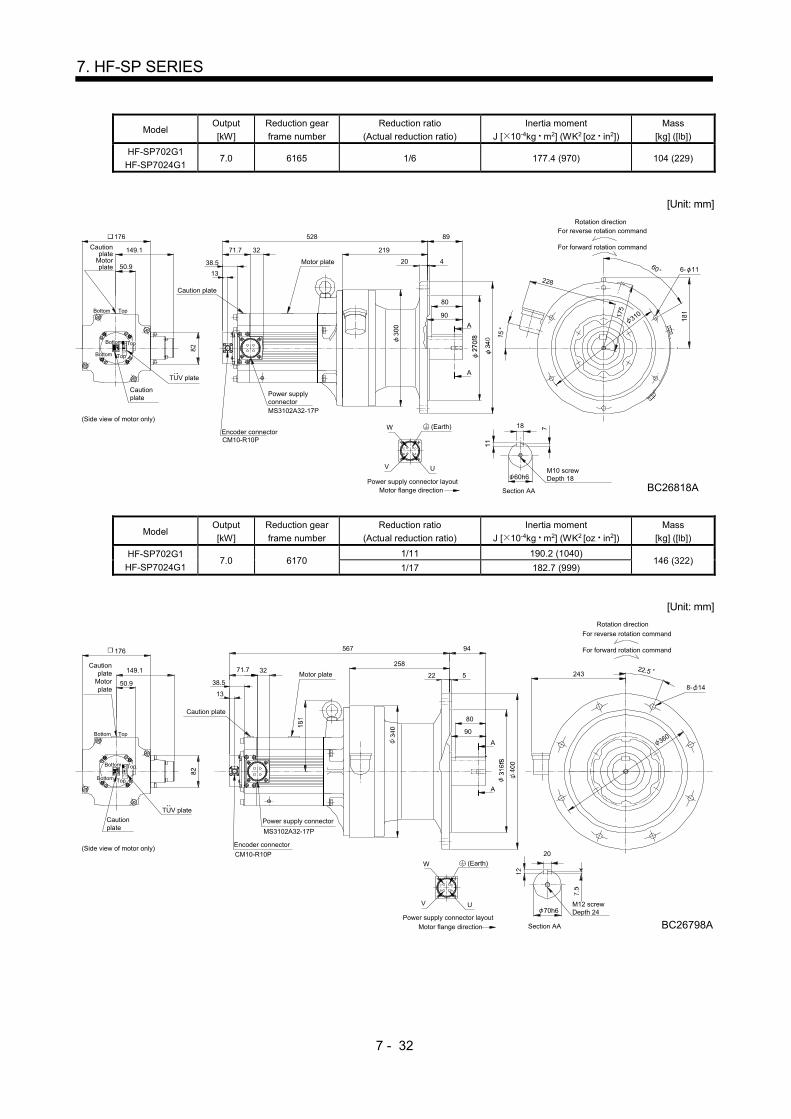
7 - 32
7. HF-SP SERIES
Model Output
[kW]
Reduction gear
frame number
Reduction ratio
(Actual reduction ratio)
Inertia moment
J [ 10-4kg m2] (WK2 [oz in2])
Mass
[kg] ([lb])
HF-SP702G1
HF-SP7024G1 7.0 6165 1/6 177.4 (970) 104 (229)
[Unit: mm]
149.1
176
U
Motor flange directionPower supply connector layout
W
V
C
B
D
A
Cautionplate
Motorplate
Cautionplate
(Side view of motor only)
For reverse rotation command
For forward rotation command
Rotation direction
Section AA
TopBottom
50.9
15
228
175
60
310
6- 11
90
89
420
219
528
71.7 32
Motor plate
Caution plate
MS3102A32-17P
Power supplyconnector
Encoder connectorCM10-R10P
80
A
A
60h6
18
M10 screwDepth 18
BC26818A
TUV plate
38.5
13
(Earth)
TopBottom
Bottom Top
Model Output
[kW]
Reduction gear
frame number
Reduction ratio
(Actual reduction ratio)
Inertia moment
J [ 10-4kg m2] (WK2 [oz in2])
Mass
[kg] ([lb])
HF-SP702G1
HF-SP7024G1 7.0 6170
1/11 190.2 (1040) 146 (322)
1/17 182.7 (999)
[Unit: mm]
149.1 3271.7
176
U
Motor flange directionPower supply connector layout
W
V
C
B
D
A
Cautionplate
Motorplate
Caution plate
Motor plate
Cautionplate
(Side view of motor only) Encoder connector
CM10-R10P
Power supply connector
MS3102A32-17P
20
M12 screwDepth 24
BC26798A
70h6
36090
80
A
8- 14
22.5
94
258
522
For reverse rotation command
For forward rotation command
Rotation direction
567
Section AA
A
TopBottom
50.9
TUV plate
38.5
13
(Earth)
243
TopBottom
Bottom Top
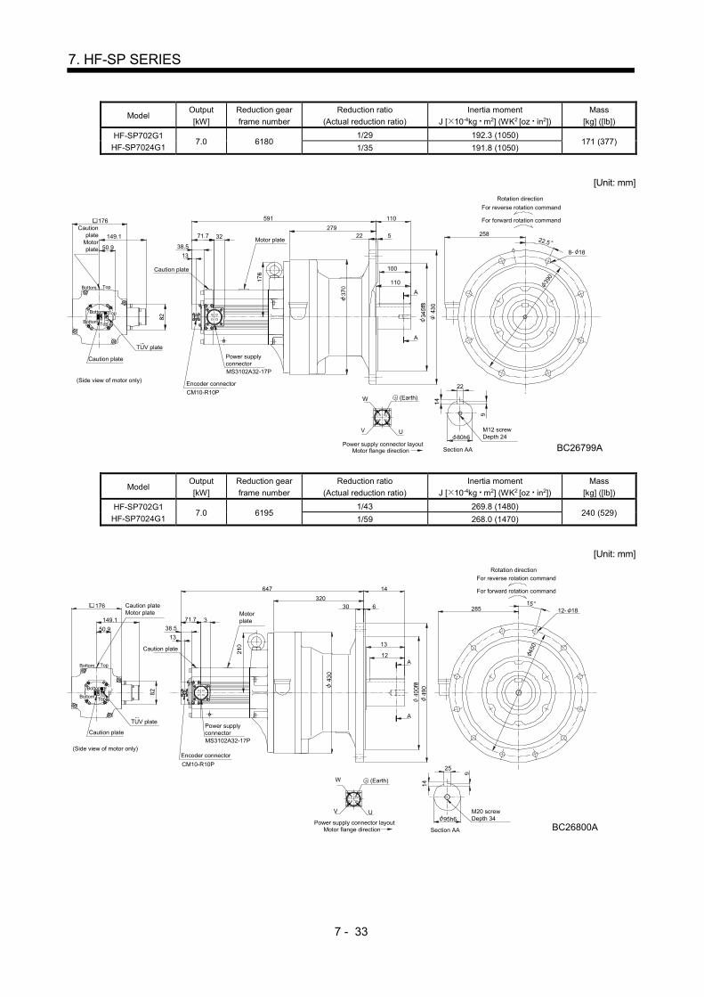
7 - 33
7. HF-SP SERIES
Model Output
[kW]
Reduction gear
frame number
Reduction ratio
(Actual reduction ratio)
Inertia moment
J [ 10-4kg m2] (WK2 [oz in2])
Mass
[kg] ([lb])
HF-SP702G1
HF-SP7024G1 7.0 6180
1/29 192.3 (1050) 171 (377)
1/35 191.8 (1050)
[Unit: mm]
149.1 3271.7
176
U
Motor flange directionPower supply connector layout
W
V
C
B
D
A
Cautionplate
Motorplate
Caution plate
Motor plate
Caution plate
(Side view of motor only)Encoder connector
CM10-R10P
Power supplyconnectorMS3102A32-17P
22
80h6M12 screwDepth 24
BC26799A
For reverse rotation command
For forward rotation command
Rotation direction
22 5
110
100
110591
22.5
390
8- 18
258279
A
A
Section AA
TopBottom
50.9
TUV plate
(Earth)
38.5
13
TopBottom
Bottom Top
Model Output
[kW]
Reduction gear
frame number
Reduction ratio
(Actual reduction ratio)
Inertia moment
J [ 10-4kg m2] (WK2 [oz in2])
Mass
[kg] ([lb])
HF-SP702G1
HF-SP7024G1 7.0 6195
1/43 269.8 (1480) 240 (529)
1/59 268.0 (1470)
[Unit: mm]
149.1 3
25
95h6
71.7
38.5
13
176
M20 screwDepth 34
BC26800A
U
Motor flange directionPower supply connector layout
W
V
C
B
D
A
Caution plateMotor plate
Caution plate
Motorplate
Caution plate
(Side view of motor only)Encoder connector
CM10-R10P
Power supplyconnectorMS3102A32-17P
For reverse rotation command
For forward rotation command
Rotation direction
30 6
647 14
12
28515
450
12- 18
320
TopBottom
Section AA
A
A
50.9
13
TUV plate
Top
TopBottom
Bottom
(Earth)
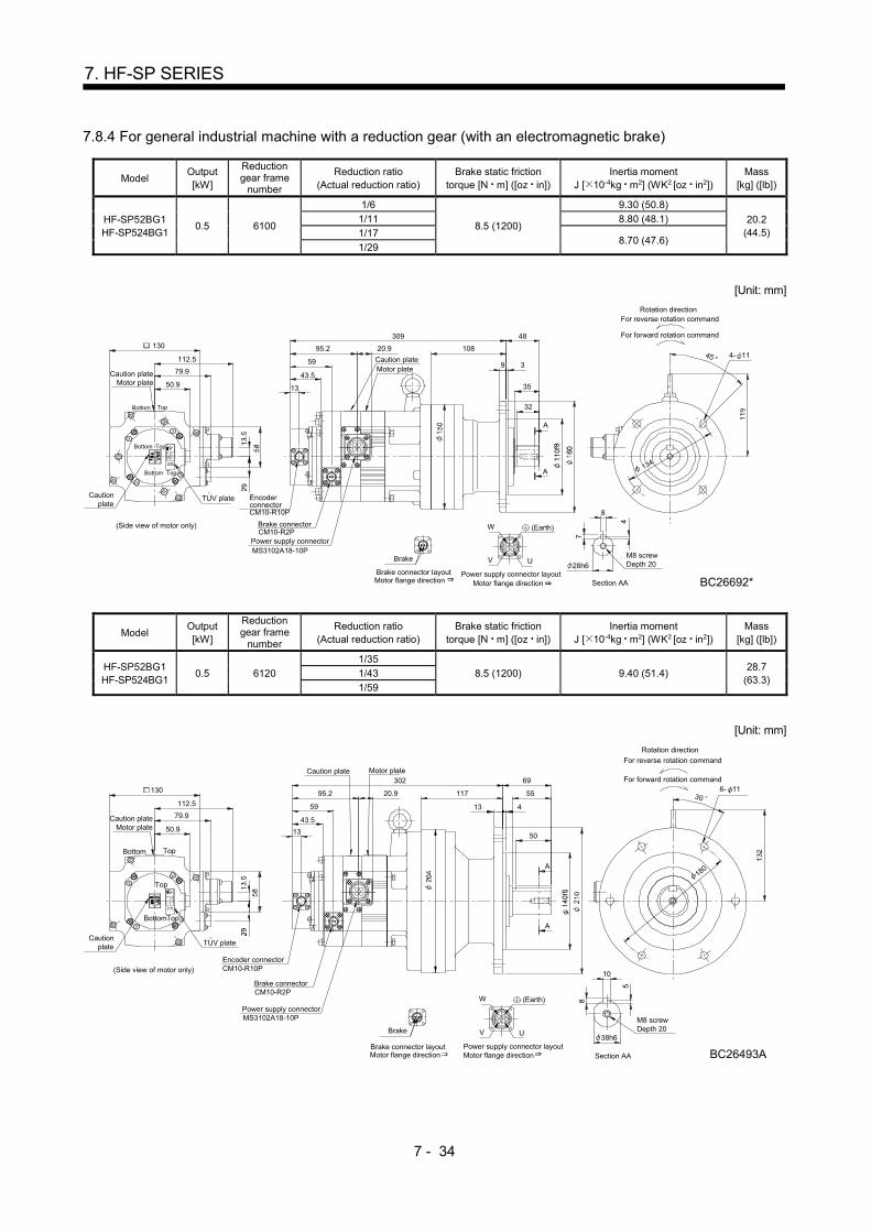
7 - 34
7. HF-SP SERIES
7.8.4 For general industrial machine with a reduction gear (with an electromagnetic brake)
Model Output [kW]
Reduction gear frame
number
Reduction ratio (Actual reduction ratio)
Brake static friction torque [N m] ([oz in])
Inertia moment J [ 10-4kg m2] (WK2 [oz in2])
Mass [kg] ([lb])
HF-SP52BG1 HF-SP524BG1
0.5 6100
1/6
8.5 (1200)
9.30 (50.8)
20.2 (44.5)
1/11 8.80 (48.1)
1/17 8.70 (47.6)
1/29
[Unit: mm]
Motor flange direction
V U
Power supply connector layout
B
W
CAD
(Side view of motor only)
50.9
112.5
130
13
59
43.5
309 48
108
35
32
Section AA
28h6
8
EncoderconnectorCM10-R10P
Rotation direction
For forward rotation command
For reverse rotation command
Motor plate79.9
TUV plate
Power supply connectorMS3102A18-10P
CM10-R2PBrake connector
Caution plate
95.2 20.9
Brake
Brake connector layout
A
A
Cautionplate
Caution plateMotor plate
M8 screwDepth 20
BC26692*Motor flange direction
9 3
134
4- 1145
(Earth)
Top
TopBottom
TopBottom
Bottom
Model Output [kW]
Reduction gear frame
number
Reduction ratio (Actual reduction ratio)
Brake static friction torque [N m] ([oz in])
Inertia moment J [ 10-4kg m2] (WK2 [oz in2])
Mass [kg] ([lb])
HF-SP52BG1 HF-SP524BG1
0.5 6120
1/35
8.5 (1200) 9.40 (51.4) 28.7
(63.3) 1/43
1/59
[Unit: mm]
Motor flange direction
V U
Power supply connector layout
B
W
CAD
Section AA
180
55117
69
38h6
10
For reverse rotation command
For forward rotation command
Rotation direction
306- 11
50
A
A
M8 screwDepth 20
BC26493A
Caution plateMotor plate
95.2
Caution plate
Brake connectorCM10-R2P
MS3102A18-10PPower supply connector
TUV plate
79.9
Encoder connectorCM10-R10P
59
43.5
13
130
112.5
50.9
(Side view of motor only)
Cautionplate
Motor plate
20.9
302
Motor flange directionBrake connector layout
Brake
13 4
(Earth)
Bottom Top
Bottom
Top
Top

7 - 35
7. HF-SP SERIES
Model Output [kW]
Reduction gear frame
number
Reduction ratio (Actual reduction ratio)
Brake static friction torque [N m] ([oz in])
Inertia moment J [ 10-4kg m2] (WK2 [oz in2])
Mass [kg] ([lb])
HF-SP102BG1 HF-SP1024BG1
1.0 6120
1/6
8.5 (1200)
17.5 (95.7)
30.5 (67.2)
1/11 16.0 (87.5)
1/17 15.6 (85.3)
1/29 15.3 (83.7)
1/35
[Unit: mm]
Motor flange direction
V U
Power supply connector layout
B
W
CAD
(Side view of motor only)
50.9
112.5
130
13
59
324
Encoder connectorCM10-R10P
79.9
TUV plate
Power supply connector
MS3102A18-10P
CM10-R2PBrake connector
95.2
Brake
Brake connector layoutMotor flange direction
180
6- 11
For reverse rotation command
For forward rotation command
Rotation direction
10
38h6
Section AA
69
117
5550
A
A
30
M8 screwDepth 20
BC26693*
20.9
Caution plate Motor plate
Caution plateMotor plate
Cautionplate
13 4
43.5
(Earth)
Top
TopBottom
BottomTop
Model Output [kW]
Reduction gear frame
number
Reduction ratio (Actual reduction ratio)
Brake static friction torque [N m] ([oz in])
Inertia moment J [ 10-4kg m2] (WK2 [oz in2])
Mass [kg] ([lb])
HF-SP102BG1 HF-SP1024BG1
1.0 6130 1/43 8.5 (1200) 16.5 (90.2) 49.5 (109)
[Unit: mm]
Motor flange direction
V U
Power supply connector layout
B
W
CAD
Brake
Brake connector layoutMotor flange direction
95.2
Brake connectorCM10-R2P
MS3102A18-10PPower supply connector
TUV plate
79.9
Encoder connectorCM10-R10P
369
59
43.5
13
112.5
50.9
(Side view of motor only)
130
For reverse rotation command
For forward rotation command
Rotation direction
76
164
50h6
14
Section AA
M10 screwDepth 18
BC26694*
20.9
Motor plate
Caution plate
Cautionplate
Motorplate
Cautionplate
15 4
230
60
208 6- 11
56
A
A
70
(Earth)
Bottom Top
BottomTop
BottomTop
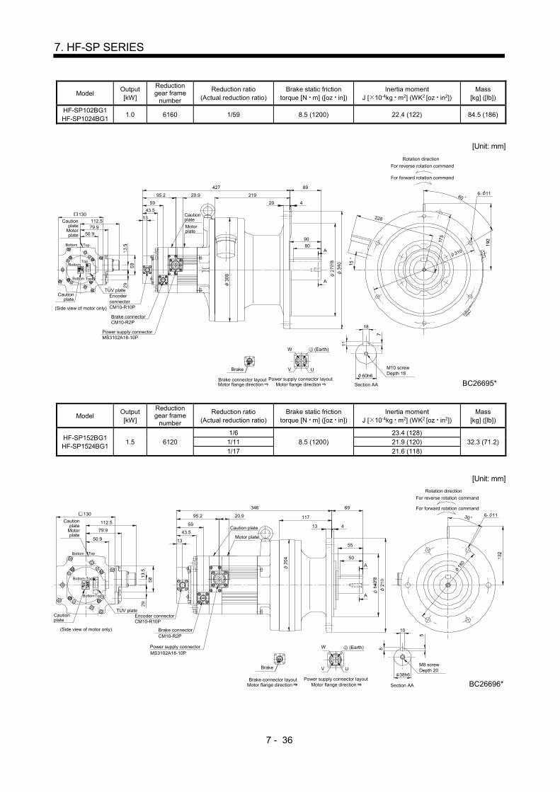
7 - 36
7. HF-SP SERIES
Model Output [kW]
Reduction gear frame
number
Reduction ratio (Actual reduction ratio)
Brake static friction torque [N m] ([oz in])
Inertia moment J [ 10-4kg m2] (WK2 [oz in2])
Mass [kg] ([lb])
HF-SP102BG1 HF-SP1024BG1
1.0 6160 1/59 8.5 (1200) 22.4 (122) 84.5 (186)
[Unit: mm]
130
(Side view of motor only)
50.9
112.513
59
427
79.9
TUV plate
95.2 6- 11
For reverse rotation command
For forward rotation command
Rotation direction
219
89
310
Brake connector layout
Brake
DA
C
W
B
Power supply connector layout
UV
Motor flange direction
M10 screwDepth 18
BC26695*60h6
18
Section AA
6020.9
EncoderconnectorCM10-R10P
Brake connectorCM10-R2P
Power supply connectorMS3102A18-10P
Cautionplate
Motorplate
Cautionplate
Cautionplate
Motorplate
20 4
228
15
175
90
A
A80
43.5
Motor flange direction
(Earth)
TopBottom
TopBottom
Bottom Top
Model Output [kW]
Reduction gear frame
number
Reduction ratio (Actual reduction ratio)
Brake static friction torque [N m] ([oz in])
Inertia moment J [ 10-4kg m2] (WK2 [oz in2])
Mass [kg] ([lb])
HF-SP152BG1 HF-SP1524BG1
1.5 6120
1/6
8.5 (1200)
23.4 (128)
32.3 (71.2) 1/11 21.9 (120)
1/17 21.6 (118)
[Unit: mm]
Motor flange direction
V U
Power supply connector layout
B
W
CAD
(Side view of motor only)
50.9
112.5
130
13
59
43.5
346
Encoder connectorCM10-R10P
79.9
TUV plate
Power supply connectorMS3102A18-10P
CM10-R2PBrake connector
95.2
Brake
Brake connector layoutMotor flange direction
A
A
6- 11
180
50
55
117
69
For reverse rotation command
For forward rotation command
Rotation direction
Section AA
38h6
10
30
M8 screwDepth 20
BC26696*
20.9
Motor plate
Caution plate
Cautionplate
Cautionplate
Motorplate
13 4
(Earth)
TopBottom
TopBottom
BottomTop
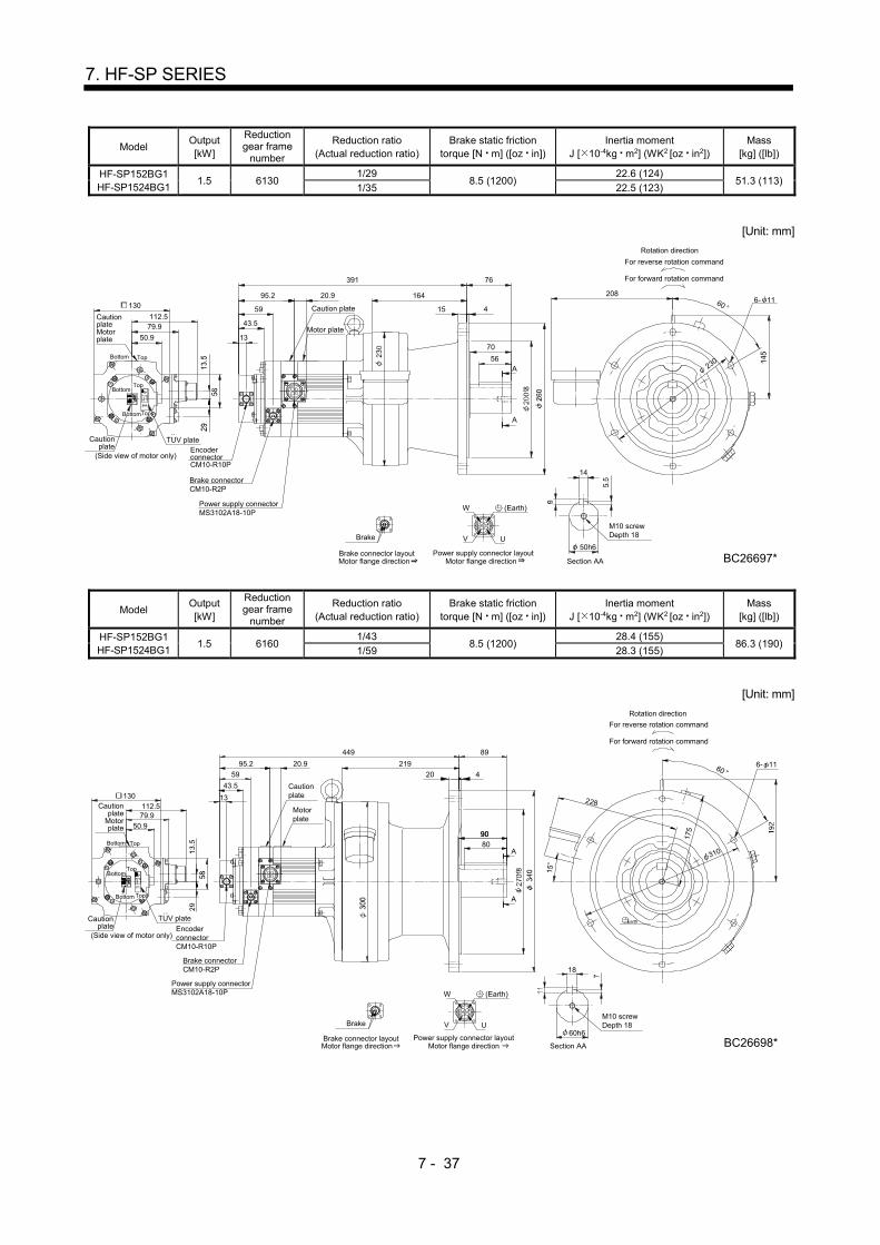
7 - 37
7. HF-SP SERIES
Model Output [kW]
Reduction gear frame
number
Reduction ratio (Actual reduction ratio)
Brake static friction torque [N m] ([oz in])
Inertia moment J [ 10-4kg m2] (WK2 [oz in2])
Mass [kg] ([lb])
HF-SP152BG1 HF-SP1524BG1
1.5 6130 1/29
8.5 (1200) 22.6 (124)
51.3 (113) 1/35 22.5 (123)
[Unit: mm]
Motor flange direction
V U
Power supply connector layout
B
W
CAD
Brake
Brake connector layoutMotor flange direction
95.2
TUV plate
79.9
391
59
13
130
112.5
50.9
(Side view of motor only)
70
76
164
Rotation direction
For forward rotation command
For reverse rotation command
Section AA
M10 screwDepth 18
BC26697*50h6
14
EncoderconnectorCM10-R10P
Brake connectorCM10-R2P
Power supply connectorMS3102A18-10P
Motor plate
Caution plate
Cautionplate
CautionplateMotorplate
20.9
15 4
20860
6- 11
23056
A
A
43.5
(Earth)
Bottom Top
BottomTop
TopBottom
Model Output [kW]
Reduction gear frame
number
Reduction ratio (Actual reduction ratio)
Brake static friction torque [N m] ([oz in])
Inertia moment J [ 10-4kg m2] (WK2 [oz in2])
Mass [kg] ([lb])
HF-SP152BG1 HF-SP1524BG1
1.5 6160 1/43
8.5 (1200) 28.4 (155)
86.3 (190) 1/59 28.3 (155)
[Unit: mm]
Earth
Motor flange direction
V U
Power supply connector layout
B
W
CAD
Brake
Brake connector layoutMotor flange direction
Brake connectorCM10-R2P
EncoderconnectorCM10-R10P
(Side view of motor only)
50.9
112.5130 13
59
79.9
TUV plate
95.2
Power supply connectorMS3102A18-10P
89
219
310
6- 11
M10 screwDepth 18
BC26698*60h6
18
Section AA
60
For reverse rotation command
For forward rotation command
Rotation direction
449
20.9
Motorplate
Cautionplate
Cautionplate
Cautionplate
Motorplate
20 4
15
228
175
80A
A
9090
43.5
(Earth)
TopBottom
TopBottom
Bottom Top
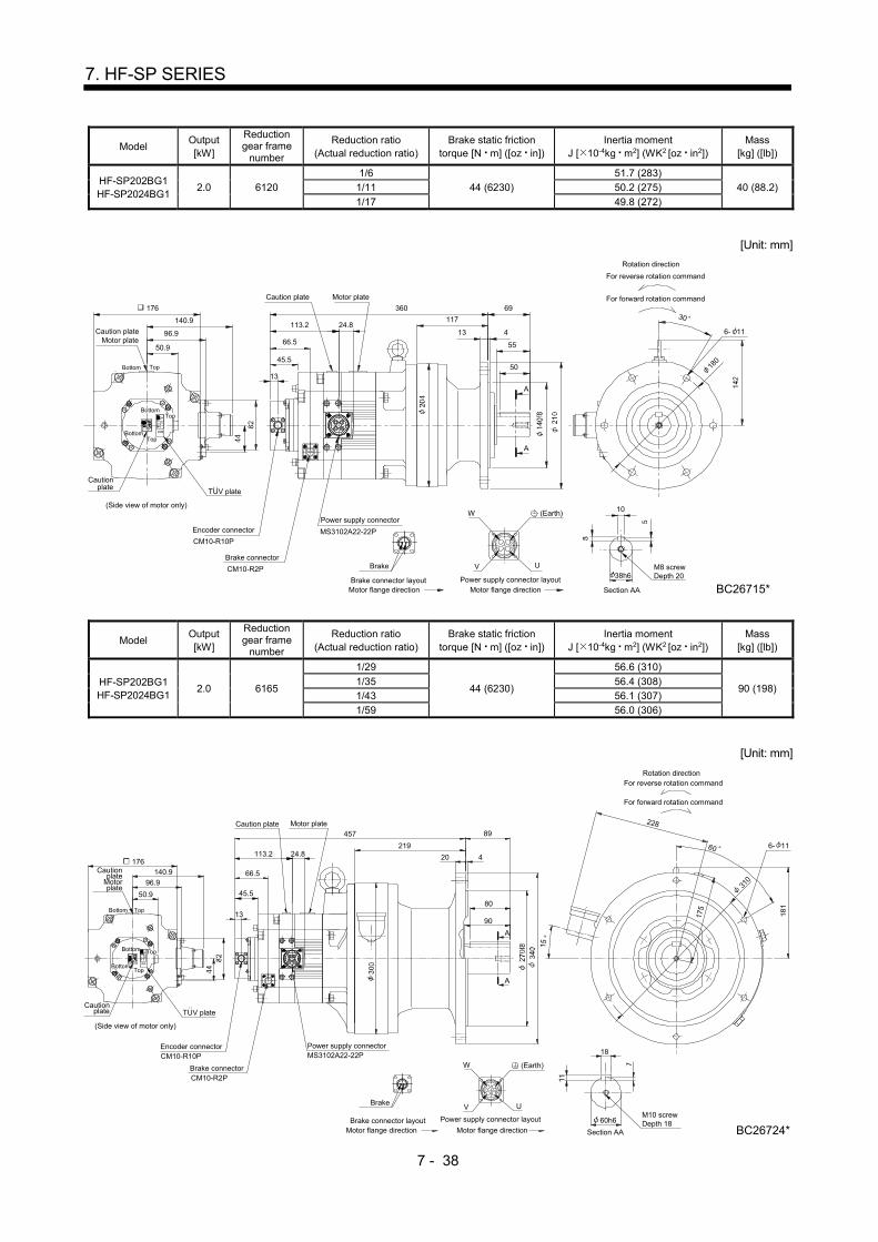
7 - 38
7. HF-SP SERIES
Model Output [kW]
Reduction gear frame
number
Reduction ratio (Actual reduction ratio)
Brake static friction torque [N m] ([oz in])
Inertia moment J [ 10-4kg m2] (WK2 [oz in2])
Mass [kg] ([lb])
HF-SP202BG1 HF-SP2024BG1
2.0 6120
1/6
44 (6230)
51.7 (283)
40 (88.2) 1/11 50.2 (275)
1/17 49.8 (272)
[Unit: mm]
Motor plateCaution plate
360
117
13 4
69
6- 11
30
10
A
A
Section AA
38h6
ABC D
UV
W
Power supply connector layoutMotor flange direction
Brake
Brake connector layoutMotor flange direction
Encoder connector
Brake connector
CM10-R10P
CM10-R2P
Power supply connector
MS3102A22-22P
M8 screwDepth 20
BC26715*
55
5013
113.2 24.8
180
Caution plateMotor plate
TopBottom
TopBottom
50.9
140.9
176
Cautionplate
(Side view of motor only)
96.966.5
(Earth)
TUV plate
For reverse rotation command
For forward rotation command
Rotation direction
45.5
BottomTop
Model Output [kW]
Reduction gear frame
number
Reduction ratio (Actual reduction ratio)
Brake static friction torque [N m] ([oz in])
Inertia moment J [ 10-4kg m2] (WK2 [oz in2])
Mass [kg] ([lb])
HF-SP202BG1 HF-SP2024BG1
2.0 6165
1/29
44 (6230)
56.6 (310)
90 (198) 1/35 56.4 (308)
1/43 56.1 (307)
1/59 56.0 (306)
[Unit: mm]
228
15
Motor plateCaution plate
ABC D
UV
W
Power supply connector layout
Motor flange direction
Brake
Brake connector layoutMotor flange direction
Encoder connector
Brake connector
CM10-R10P
CM10-R2P
Power supply connectorMS3102A22-22P
113.2
13
457
219
20 4
60 6- 1124.8
M10 screwDepth 18
BC26724*60h6
18
Section AA
31096.9
Cautionplate TUV plate
176140.9
50.9
Top
Bottom Top
Cautionplate
Motorplate
(Side view of motor only)
175
80
90
A
A
89
66.5
For reverse rotation command
For forward rotation command
Rotation direction
45.5
(Earth)
Bottom
Bottom
Top

7 - 39
7. HF-SP SERIES
Model Output [kW]
Reduction gear frame
number
Reduction ratio (Actual reduction ratio)
Brake static friction torque [N m] ([oz in])
Inertia moment J [ 10-4kg m2] (WK2 [oz in2])
Mass [kg] ([lb])
HF-SP352BG1 HF-SP3524BG1
3.5 6135
6135
44 (6230)
94.0 (514)
63 (139) 1/11 89.8 (491)
1/17 88.5 (484)
[Unit: mm]
A
A
Encoder connector
Brake connector
CM10-R10P
CM10-R2P
Power supply connectorMS3102A22-22P
113.2
1356
70
415
164
76442
M10 screwDepth 18
BC26719*Motor flange directionBrake connector layout
Brake
Motor flange directionPower supply connector layout
W
V U
DCB A
Section AA
50h6
14
Caution plate
Motor plate
24.8
60
6- 11208
230
96.9
Cautionplate TUV plate
176
140.9
50.9
Top
Bottom Top
Cautionplate
Motorplate
(Side view of motor only)
66.5
Rotation direction
For forward rotation command
For reverse rotation command
45.5
(Earth)
Bottom
BottomTop
Model Output [kW]
Reduction gear frame
number
Reduction ratio (Actual reduction ratio)
Brake static friction torque [N m] ([oz in])
Inertia moment J [ 10-4kg m2] (WK2 [oz in2])
Mass [kg] ([lb])
HF-SP352BG1 HF-SP3524BG1
3.5 6165 1/29
44 (6230) 93.6 (512)
97 (214) 1/35 93.3 (510)
[Unit: mm]
Encoder connector
Brake connector
CM10-R10P
CM10-R2P
Power supply connectorMS3102A22-22P
Motor flange directionBrake connector layout
Brake
Motor flange directionPower supply connector layout
W
V U
DCB A
89
219
420
A
A
60
310
497
M10 screwDepth 18
BC26721*60h6
Section AA
18
Rotation direction
For forward rotation command
For reverse rotation command
24.8113.2
13
Caution plate
Motor plate
15
228
96.9
Cautionplate TUV plate
176140.9
50.9
Bottom Top
Cautionplate
Motorplate
(Side view of motor only)
175
6- 11
90
80
66.5
90
80
90
80
45.5
(Earth)
TopBottom
BottomTop
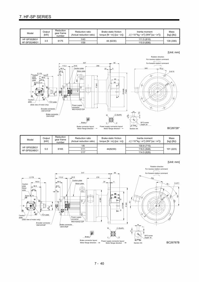
7 - 40
7. HF-SP SERIES
Model Output [kW]
Reduction gear frame
number
Reduction ratio (Actual reduction ratio)
Brake static friction torque [N m] ([oz in])
Inertia moment J [ 10-4kg m2] (WK2 [oz in2])
Mass [kg] ([lb])
HF-SP352BG1 HF-SP3524BG1
3.5 6175 1/43
44 (6230) 111.5 (610)
139 (306) 1/59 110.9 (606)
[Unit: mm]
Encoder connector
Brake connector
CM10-R10P
CM10-R2P
Power supplyconnectorMS3102A22-22P
Motor flange directionBrake connector layout
Brake
Motor flange directionPower supply connector layout
W
V U
DCB A
Motor plate
Caution plate
537
13
66.5
113.2 24.8 258
94
522
80
M12 screwDepth 24
BC26726*70h6
Section AA
20
For reverse rotation command
For forward rotation command
Rotation direction
8- 14
22.5
36090
A
A
96.9
Cautionplate TUV plate
176140.9
50.9
Bottom Top
CautionplateMotorplate
(Side view of motor only)
45.5
(Earth)
243
TopBottom
BottomTop
Model Output [kW]
Reduction gear frame
number
Reduction ratio (Actual reduction ratio)
Brake static friction torque [N m] ([oz in])
Inertia moment J [ 10-4kg m2] (WK2 [oz in2])
Mass [kg] ([lb])
HF-SP502BG1 HF-SP5024BG1
5.0 6165
1/6
44(6230)
130.8 (715)
101 (223) 1/11 118.5 (648)
1/17 114.5 (626)
[Unit: mm]
Motor flange direction
Brake connector layout
Brake
Motor flange directionPower supply connector layout
W
V U
DCB A
89
219
A
60
310
517
M10 screwDepth 18
BC26787B60h6
Section AA
18
Rotation direction
For forward rotation command
For reverse rotation command
15
228
96.9
Cautionplate
176
140.9
50.9
Bottom Top
CautionplateMotorplate
(Side view of motor only)
90
80
90
80
90
80
Power supplyconnector
Brake connectorEncoder connector
CM10-R2PCM10-R10P
MS3102A22-22P
Caution plate66.5
13
113.2
Motor plate
24.8
6- 1120 4
175
TUV plate
A
45.5
(Earth)
TopBottom
BottomTop
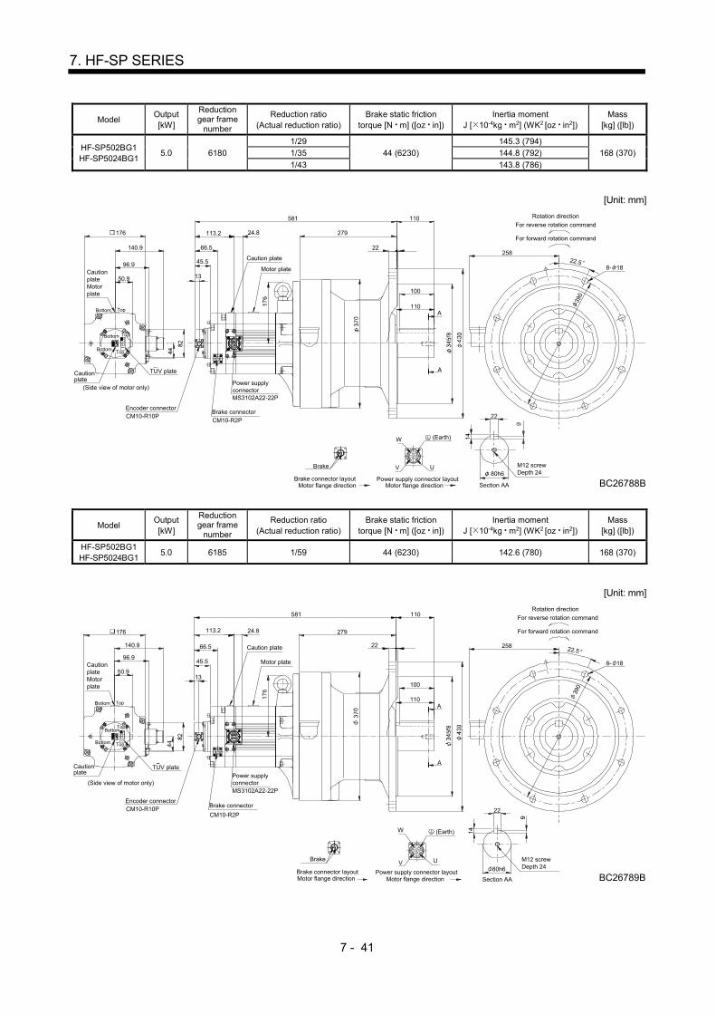
7 - 41
7. HF-SP SERIES
Model Output [kW]
Reduction gear frame
number
Reduction ratio (Actual reduction ratio)
Brake static friction torque [N m] ([oz in])
Inertia moment J [ 10-4kg m2] (WK2 [oz in2])
Mass [kg] ([lb])
HF-SP502BG1 HF-SP5024BG1
5.0 6180
1/29
44 (6230)
145.3 (794)
168 (370) 1/35 144.8 (792)
1/43 143.8 (786)
[Unit: mm]
Motor flange directionBrake connector layout
Brake
Motor flange directionPower supply connector layout
W
V U
DCB A
Section AA
Rotation direction
For forward rotation command
For reverse rotation command
96.9
Cautionplate
176
140.9
50.9
Top
Bottom Top
CautionplateMotorplate
(Side view of motor only)Power supplyconnector
Brake connectorEncoder connector
CM10-R2PCM10-R10P
MS3102A22-22P
Caution plate
66.5
13
113.2
Motor plate
24.8
581 110
110
100
258
279
390
8- 18
A
A
22
80h6
M12 screwDepth 24
BC26788B
22
22.5
TUV plate
45.5
(Earth)
Bottom
TopBottom
Model Output [kW]
Reduction gear frame
number
Reduction ratio (Actual reduction ratio)
Brake static friction torque [N m] ([oz in])
Inertia moment J [ 10-4kg m2] (WK2 [oz in2])
Mass [kg] ([lb])
HF-SP502BG1 HF-SP5024BG1
5.0 6185 1/59 44 (6230) 142.6 (780) 168 (370)
[Unit: mm]
45.5
(Earth)
Motor flange directionBrake connector layout
Brake
Motor flange directionPower supply connector layout
W
V U
DCB A
Rotation direction
For forward rotation command
For reverse rotation command
96.9
Cautionplate
176
140.9
50.9
Top
Bottom Top
CautionplateMotorplate
(Side view of motor only)Power supplyconnector
Brake connectorEncoder connector
CM10-R2PCM10-R10P
MS3102A22-22P
Caution plate66.5
13
113.2
Motor plate
24.8
581 110
110
100
258
279
390
8- 18
M12 screwDepth 24
BC26789B80h6
22
Section AA
A
A
2222.5
TUV plate
Bottom
TopBottom
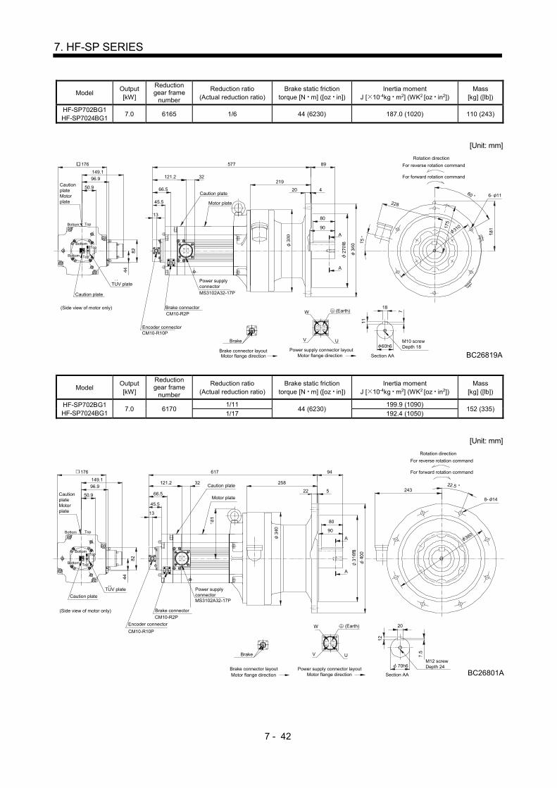
7 - 42
7. HF-SP SERIES
Model Output [kW]
Reduction gear frame
number
Reduction ratio (Actual reduction ratio)
Brake static friction torque [N m] ([oz in])
Inertia moment J [ 10-4kg m2] (WK2 [oz in2])
Mass [kg] ([lb])
HF-SP702BG1 HF-SP7024BG1
7.0 6165 1/6 44 (6230) 187.0 (1020) 110 (243)
[Unit: mm]
U
Motor flange directionPower supply connector layout
W
V
C
B
D
A
176
96.9
149.1
CautionplateMotorplate
Caution plate
TopBottom
Top
Section AAMotor flange directionBrake connector layout
Brake
50.9
80
89
90
4
219
20
A
A
MS3102A32-17P
Power supplyconnector
Encoder connector
Brake connectorCM10-R2P
Caution plate
13
Motor plate
66.5
121.2 32
577
310
228
15
For forward rotation command
For reverse rotation command
Rotation direction
6- 1160
175
60h6
18
M10 screwDepth 18
BC26819A
CM10-R10P
(Side view of motor only)
Bottom
TUV plate
45.5
(Earth)
Bottom
Top
Model Output [kW]
Reduction gear frame
number
Reduction ratio (Actual reduction ratio)
Brake static friction torque [N m] ([oz in])
Inertia moment J [ 10-4kg m2] (WK2 [oz in2])
Mass [kg] ([lb])
HF-SP702BG1 HF-SP7024BG1
7.0 6170 1/11
44 (6230) 199.9 (1090)
152 (335) 1/17 192.4 (1050)
[Unit: mm]
U
Motor flange directionPower supply connector layout
W
V
C
B
D
A
20
M12 screwDepth 24
BC26801A70h6
36090
80
A
A
8- 14
22.5
94
258
522
For reverse rotation command
For forward rotation command
Rotation direction
617
Caution plate
13
32121.2
66.5Motor plate
Power supplyconnectorMS3102A32-17P
CM10-R2P
Brake connector
Encoder connector
CM10-R10P
176
96.9
149.1
CautionplateMotorplate
Caution plate
TopBottom
Top
Section AAMotor flange directionBrake connector layout
Brake
50.9
(Side view of motor only)
TUV plate
45.5
(Earth)
243
Bottom
BottomTop
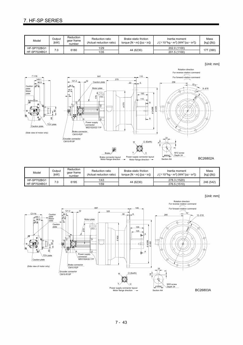
7 - 43
7. HF-SP SERIES
Model Output [kW]
Reduction gear frame
number
Reduction ratio (Actual reduction ratio)
Brake static friction torque [N m] ([oz in])
Inertia moment J [ 10-4kg m2] (WK2 [oz in2])
Mass [kg] ([lb])
HF-SP702BG1 HF-SP7024BG1
7.0 6180 1/29
44 (6230) 202.0 (1100)
177 (390) 1/35 201.5 (1100)
[Unit: mm]
U
Motor flange directionPower supply connector layout
W
V
C
B
D
A
22
80h6M12 screwDepth 24
BC26802A
For reverse rotation command
For forward rotation command
Rotation direction
22 5
110
100
110641
22.5
390
8- 18
258
Motor plate
Caution plate
13
32121.2
66.5
Power supplyconnectorMS3102A32-17P
CM10-R2P
Brake connector
Encoder connectorCM10-R10P
176
96.9
149.1
CautionplateMotorplate
Caution plate
Brake
Brake connector layoutMotor flange direction
279
TopBottom
Top
Section AA
A
A
50.9
(Side view of motor only)
TUV plate
45.5
(Earth)
Bottom
Bottom
Top
Model Output [kW]
Reduction gear frame
number
Reduction ratio (Actual reduction ratio)
Brake static friction torque [N m] ([oz in])
Inertia moment J [ 10-4kg m2] (WK2 [oz in2])
Mass [kg] ([lb])
HF-SP702BG1 HF-SP7024BG1
7.0 6195 1/43
44 (6230) 278.3 (1520)
246 (542) 1/59 276.5 (1510)
[Unit: mm]
50.9
135
TUV plate
25
95h6M20 screwDepth 34
BC26803A
U
Motor flange directionPower supply connector layout
W
V
C
B
D
A
For reverse rotation command
For forward rotation command
Rotation direction
30 6
697 145
125
28515
450
12- 18
320176
96.9149.1
(Side view of motor only)
Caution plate
CautionplateMotorplate
Motor plate
Cautionplate
13
32121.2
66.5
Power supplyconnectorMS3102A32-17P
CM10-R2PBrake connector
Encoder connector
CM10-R10P
A
A
Section AA
45.5
(Earth)
TopBottom
Bottom Top

7 - 44
7. HF-SP SERIES
7.8.5 For general industrial machine with a reduction gear (leg type without an electromagnetic brake)
Model Output
[kW]
Reduction gear
frame number
Reduction ratio
(Actual reduction ratio)
Inertia moment
J [ 10-4kg m2] (WK2 [oz in2])
Mass
[kg] ([lb])
HF-SP52G1H
HF-SP524G1H 0.5 6100
1/6 7.10 (38.8)
20.8 (45.9) 1/11 6.70 (36.6)
1/17 6.60 (36.1)
1/29 6.50 (35.5)
[Unit: mm]
Motor flange direction
V U
Power supply connector layout
B
W
CAD
323Rotation direction
For forward rotation command
For reverse rotation command
121 35
15
60
135 180
4075 754- 11
A
A
45 45
TUV plate
(Side view of motor only)
112.5Caution plateMotor plate
130
50.9Cautionplate
Power supply connectorMS3102A18-10P
Encoder connectorCM10-R10P
Caution plate
60.7
13
20.9
Motor plate 32
M8 screwDepth 20
BC26699*
8
28h6
Section AA
38.2
(Earth)
Bottom Top
Bottom
Bottom
Top
Top
Model Output
[kW]
Reduction gear
frame number
Reduction ratio
(Actual reduction ratio)
Inertia moment
J [ 10-4kg m2] (WK2 [oz in2])
Mass
[kg] ([lb])
HF-SP52G1H
HF-SP524G1H 0.5 6120
1/35 7.30 (39.9)
27.8 (61.3) 1/43
1/59 7.20 (39.4)
[Unit: mm]
V U
Power supply connector layout
B
W
CAD
TUV plate
(Side view of motor only)
50.9
112.5
130
13
60.7
EncoderconnectorCM10-R10P
Power supply connectorMS3102A18-10P
20.9
Motor plate
Caution plate
Cautionplate
CautionplateMotorplate
38h6
10
M8 screwDepth 20
BC26490*
5595
230
95
Rotation direction
For forward rotation command
For reverse rotation command
50
A
A
8220
57.557.5
155
131 55
337
4- 14
Section AAMotor flange direction
38.2
(Earth)
Top
Top
TopBottom
Bottom
Bottom
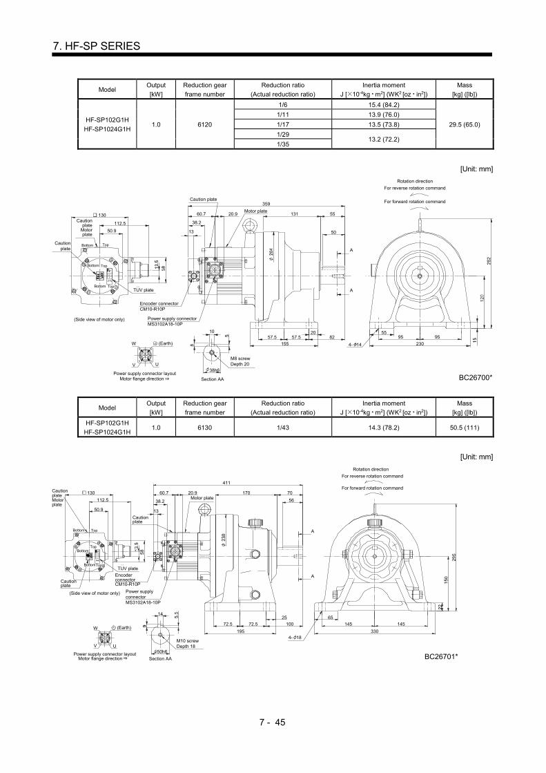
7 - 45
7. HF-SP SERIES
Model Output
[kW]
Reduction gear
frame number
Reduction ratio
(Actual reduction ratio)
Inertia moment
J [ 10-4kg m2] (WK2 [oz in2])
Mass
[kg] ([lb])
HF-SP102G1H
HF-SP1024G1H 1.0 6120
1/6 15.4 (84.2)
29.5 (65.0)
1/11 13.9 (76.0)
1/17 13.5 (73.8)
1/29 13.2 (72.2)
1/35
[Unit: mm]
V U
Power supply connector layout
B
W
CAD
Section AA
Rotation direction
For forward rotation command
For reverse rotation command
38h6
230
5595 95
4- 14155
57.520
57.5
359
131 55
A
ATUV plate
(Side view of motor only)
112.5Caution
plateMotorplate
130
50.9
Cautionplate
Power supply connectorMS3102A18-10P
Motor plate20.960.7
13
Encoder connectorCM10-R10P
Caution plate
50
10
Motor flange direction
M8 screwDepth 20
BC26700*
82
38.2
(Earth)
Bottom
Bottom Top
Top
Bottom Top
Model Output
[kW]
Reduction gear
frame number
Reduction ratio
(Actual reduction ratio)
Inertia moment
J [ 10-4kg m2] (WK2 [oz in2])
Mass
[kg] ([lb])
HF-SP102G1H
HF-SP1024G1H 1.0 6130 1/43 14.3 (78.2) 50.5 (111)
[Unit: mm]
Motor flange direction
V U
Power supply connector layout
B
W
CAD
TUV plate
(Side view of motor only)
50.9
112.5
130
13
60.7
Section AA
EncoderconnectorCM10-R10P
Power supplyconnectorMS3102A18-10P
14
50h6
M10 screwDepth 18
BC26701*
20.9Motor plate
Cautionplate
Cautionplate
CautionplateMotorplate
145 145
195 330
72.5 72.5
25 65
411
70
56
A
A
170
For reverse rotation command
For forward rotation command
100
4- 18
Rotation direction
38.2
(Earth)
TopBottom
TopBottom
BottomTop
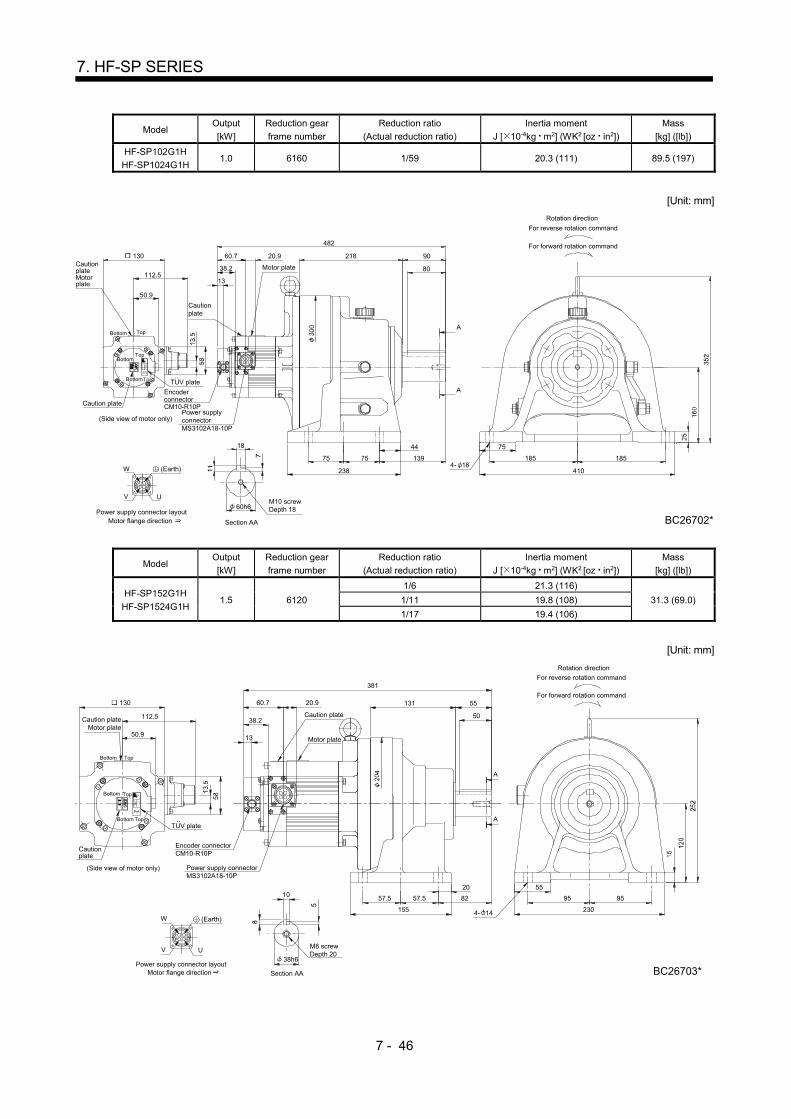
7 - 46
7. HF-SP SERIES
Model Output
[kW]
Reduction gear
frame number
Reduction ratio
(Actual reduction ratio)
Inertia moment
J [ 10-4kg m2] (WK2 [oz in2])
Mass
[kg] ([lb])
HF-SP102G1H
HF-SP1024G1H 1.0 6160 1/59 20.3 (111) 89.5 (197)
[Unit: mm]
Motor flange direction
V U
Power supply connector layout
B
W
CAD
Section AA
Power supplyconnectorMS3102A18-10P
EncoderconnectorCM10-R10P
60.7
13
130
112.5
50.9
(Side view of motor only)
TUV plate
18
60h6M10 screwDepth 18
Cautionplate
CautionplateMotorplate
Caution plate
410
185 185
75
238
BC26702*
44
4- 18
482
90218
Motor plate
75 75
A
A
Rotation direction
For forward rotation command
For reverse rotation command
20.9
80
139
38.2
(Earth)
Bottom Top
Bottom
BottomTop
Top
Model Output
[kW]
Reduction gear
frame number
Reduction ratio
(Actual reduction ratio)
Inertia moment
J [ 10-4kg m2] (WK2 [oz in2])
Mass
[kg] ([lb])
HF-SP152G1H
HF-SP1524G1H 1.5 6120
1/6 21.3 (116)
31.3 (69.0) 1/11 19.8 (108)
1/17 19.4 (106)
[Unit: mm]
For reverse rotation command
For forward rotation command
Rotation direction
Caution plateMotor plate
Cautionplate
Caution plate
Motor plate
20.9130
112.5
50.9
TUV plate
Power supply connectorMS3102A18-10P
Encoder connectorCM10-R10P
60.7
13
(Side view of motor only)
4- 14 230
9595
55
155
8257.557.5
20
A
A
50
55131
DA
C
W
B
Power supply connector layout
UV
Motor flange direction
M8 screwDepth 20
BC26703*
10
38h6
Section AA
381
38.2
(Earth)
Bottom Top
Bottom Top
Bottom Top

7 - 47
7. HF-SP SERIES
Model Output
[kW]
Reduction gear
frame number
Reduction ratio
(Actual reduction ratio)
Inertia moment
J [ 10-4kg m2] (WK2 [oz in2])
Mass
[kg] ([lb])
HF-SP152G1H
HF-SP1524G1H 1.5 6130
1/29 20.4 (112) 52.3 (115)
1/35
[Unit: mm]
Motor flange direction
V U
Power supply connector layout
B
W
CAD
130
112.5
50.9
TUV plate
Power supply connectorMS3102A18-10P
Encoder connectorCM10-R10P
60.7
13
(Side view of motor only)
14
50h6
M10 screwDepth 18
Section AA
20.9
Motorplate
Cautionplate
Cautionplate
Cautionplate
330
145 145
65
195
72.5 72.5
25
433
170 70
56
A
A
For reverse rotation command
For forward rotation command
Rotation direction
4- 18
BC26704*
100
38.2
(Earth)
Bottom Top
BottomTop
BottomTop
Model Output
[kW]
Reduction gear
frame number
Reduction ratio
(Actual reduction ratio)
Inertia moment
J [ 10-4kg m2] (WK2 [oz in2])
Mass
[kg] ([lb])
HF-SP152G1H
HF-SP1524G1H 1.5 6160
1/43 26.3 (144) 91.3 (201)
1/59 26.2 (143)
[Unit: mm]
Section AA
(Side view of motor only)
13
60.7
EncoderconnectorCM10-R10P
Power supplyconnectorMS3102A18-10P
TUV plate
50.9
112.5
130
DA
C
W
B
Power supply connector layout
UV
Motor flange direction
18
60h6
M10 screwDepth 18
BC26705*
20.9
MotorplateCaution
plate
CautionplateMotorplate
Cautionplate
410
185 185
75
238
75 75
44
504
218 90
80
139
4- 18
Rotation direction
For forward rotation command
For reverse rotation command
A
A
38.2
(Earth)
TopBottom
Top
Top
Bottom

7 - 48
7. HF-SP SERIES
Model Output
[kW]
Reduction gear
frame number
Reduction ratio
(Actual reduction ratio)
Inertia moment
J [ 10-4kg m2] (WK2 [oz in2])
Mass
[kg] ([lb])
HF-SP202G1H
HF-SP2024G1H 2.0 6120
1/6 42.1 (230)
35 (77.2) 1/11 40.5 (221)
1/17 40.2 (220)
[Unit: mm]
Power supply connector layoutMotor flange direction
CM10-R10P
Encoder connectorMS3102A22-22P
Power supplyconnector
V
W
AD
BC
Motor plate
Caution plate
U
38h6
Section AA
10
M8 screwDepth 20
63.7
95
2304- 14
BC26716*
5595
380
55131
13
155
57.5 57.5 82
20
50
24.8
For reverse rotation command
For forward rotation command
Rotation direction
A
A
TopBottom
50.9
140.9
176
Cautionplate
(Side view of motor only)
Caution plateMotor plate
TopBottom
(Earth)
TUV plate
38.5
TopBottom
Model Output
[kW]
Reduction gear
frame number
Reduction ratio
(Actual reduction ratio)
Inertia moment
J [ 10-4kg m2] (WK2 [oz in2])
Mass
[kg] ([lb])
HF-SP202G1H
HF-SP2024G1H 2.0 6165
1/29 46.9 (256)
91 (201) 1/35 46.7 (255)
1/43 46.4 (254)
1/59
[Unit: mm]
Power supply connector layoutMotor flange direction
CM10-R10P
Encoder connector
MS3102A22-22P
Power supplyconnector
V
W
AD
BC
Motorplate
Caution plate
U
13
63.7 24.8
18
M10 screwDepth 18
BC26737*
A
A
Section AA
447575
238
7185 185
410
8090218
497For reverse rotation command
For forward rotation command
Rotation direction
139
4- 18
50.9140.9
176
TUV plateCautionplate
(Side view of motor only)
CautionplateMotorplate
TopBottom
38.5
60h6
(Earth)
TopBottom
TopBottom

7 - 49
7. HF-SP SERIES
Model Output
[kW]
Reduction gear
frame number
Reduction ratio
(Actual reduction ratio)
Inertia moment
J [ 10-4kg m2] (WK2 [oz in2])
Mass
[kg] ([lb])
HF-SP352G1H
HF-SP3524G1H 3.5 6135
1/6 84.4 (461)
60 (132) 1/11 80.1 (438)
1/17 78.8 (431)
[Unit: mm]
14
Section AA
50h6
ABC D
UV
W
Power supply connector layoutMotor flange direction
M10 screwDepth 18
MS3102A22-22P
Power supplyconnector
63.7
13
24.8
A
A
4- 18
BC26722*
330
145145
65
195
72.5 72.5
25
170 70
56
469
Encoder connector
CM10-R10P
100
For reverse rotation commandRotation direction
For forward rotation commandMotor plate
Caution plate
50.9140.9
176
TUV plateCautionplate
(Side view of motor only)
Caution plateMotor plate
TopBottom
38.5
(Earth)
TopBottom
TopBottom
Model Output
[kW]
Reduction gear
frame number
Reduction ratio
(Actual reduction ratio)
Inertia moment
J [ 10-4kg m2] (WK2 [oz in2])
Mass
[kg] ([lb])
HF-SP352G1H
HF-SP3524G1H 3.5 6165
1/29 83.9 (459) 98 (216)
1/35 83.7 (458)
[Unit: mm]
18
Section AA
60h6
ABC D
UV
Power supply connector layoutMotor flange direction
M10 screwDepth 18
MS3102A22-22P
Power supplyconnector
Encoder connectorCM10-R10P
13
63.7 218 90
80
537
75 75
44
139
238
75
185 185
BC26732*
410
4- 18
A
A
W
Caution plate
Motor plate
24.8
50.9140.9
176
TUV plate
Cautionplate
(Side view of motor only)
CautionplateMotorplate
TopBottom
For reverse rotation command
For forward rotation command
Rotation direction
38.5
Top
(Earth)
TopBottom
Bottom
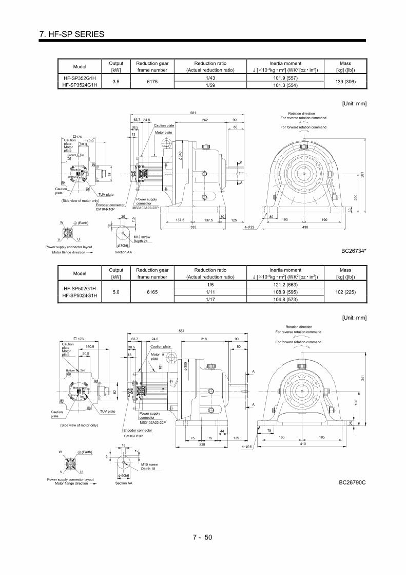
7 - 50
7. HF-SP SERIES
Model Output
[kW]
Reduction gear
frame number
Reduction ratio
(Actual reduction ratio)
Inertia moment
J [ 10-4kg m2] (WK2 [oz in2])
Mass
[kg] ([lb])
HF-SP352G1H
HF-SP3524G1H 3.5 6175
1/43 101.9 (557) 139 (306)
1/59 101.3 (554)
[Unit: mm]
20
Section AA
70h6
ABC D
UV
Power supply connector layout
Motor flange direction
MS3102A22-22P
Power supplyconnector
63.7
Encoder connectorCM10-R10P
13
262 90
80
581
30137.5137.5
335
80190 190
BC26734*
4304- 22W
A
A
M12 screwDepth 24
Caution plate
Motor plate
125
Rotation direction
For forward rotation command
For reverse rotation command24.8
CautionplateMotorplate
TopBottom
Top
50.9140.9
176
TUV plate
Cautionplate
(Side view of motor only)
38.5
(Earth)
TopBottom
Bottom
Model Output
[kW]
Reduction gear
frame number
Reduction ratio
(Actual reduction ratio)
Inertia moment
J [ 10-4kg m2] (WK2 [oz in2])
Mass
[kg] ([lb])
HF-SP502G1H
HF-SP5024G1H 5.0 6165
1/6 121.2 (663)
102 (225) 1/11 108.9 (595)
1/17 104.8 (573)
[Unit: mm]
ABC D
UV
Power supply connector layoutMotor flange direction
TopBottom
176
140.9
50.9
CautionplateMotorplate
Cautionplate
Power supplyconnector
MS3102A22-22P
Encoder connector
CM10-R10P
W
(Side view of motor only)
Rotation direction
For forward rotation command
For reverse rotation command
410
185 185
BC26790C
75
238
75 75
44
139
557
218 90
80
A
13
63.7 24.8
Caution plate
Motorplate
18
60h6
Section AA
M10 screwDepth 18
4- 18
A
TUV plate
38.5
Top
(Earth)
Bottom
TopBottom
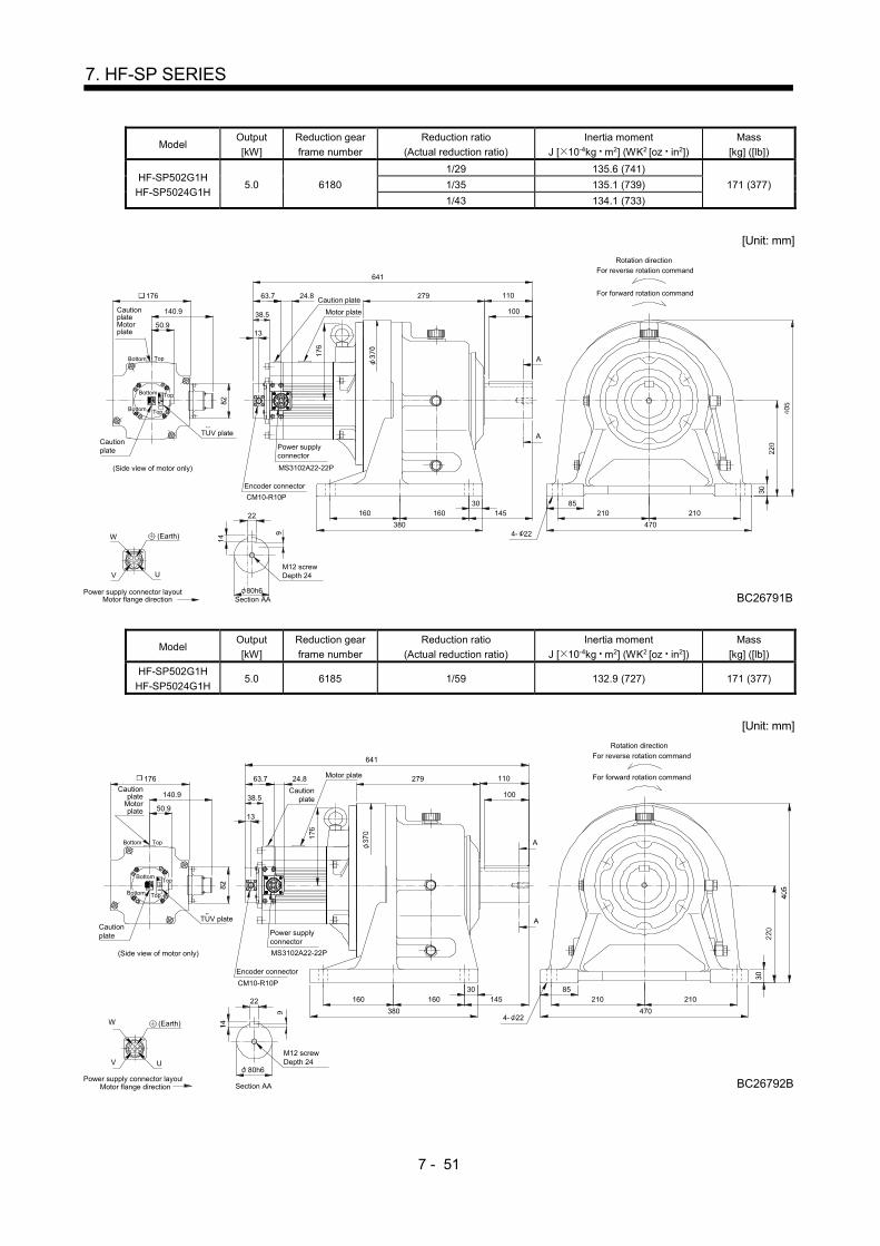
7 - 51
7. HF-SP SERIES
Model Output
[kW]
Reduction gear
frame number
Reduction ratio
(Actual reduction ratio)
Inertia moment
J [ 10-4kg m2] (WK2 [oz in2])
Mass
[kg] ([lb])
HF-SP502G1H
HF-SP5024G1H 5.0 6180
1/29 135.6 (741)
171 (377) 1/35 135.1 (739)
1/43 134.1 (733)
[Unit: mm]
ABC D
UV
Power supply connector layoutMotor flange direction
TopBottom
470
210
BC26791B
21085
380
160 16030
279 110
145
641
13
176
140.9
50.9
CautionplateMotorplate
Cautionplate
63.7 24.8
Power supplyconnector
MS3102A22-22P
Encoder connector
CM10-R10P
A
100
22
80h6Section AA
M12 screwDepth 24
W
Caution plate
Motor plate
(Side view of motor only)
Rotation direction
For forward rotation command
For reverse rotation command
4- 22
TUV plate A
38.5
Top
(Earth)
Bottom
TopBottom
Model Output
[kW]
Reduction gear
frame number
Reduction ratio
(Actual reduction ratio)
Inertia moment
J [ 10-4kg m2] (WK2 [oz in2])
Mass
[kg] ([lb])
HF-SP502G1H
HF-SP5024G1H 5.0 6185 1/59 132.9 (727) 171 (377)
[Unit: mm]
ABC D
UV
Power supply connector layoutMotor flange direction
TopBottom
470
210
BC26792B
21085
380
160 16030
279 110
145
641
13
176
140.9
50.9
Cautionplate
Motorplate
Cautionplate
63.7 24.8
Power supplyconnector
MS3102A22-22P
Encoder connector
CM10-R10P
A
100
22
80h6
Section AA
M12 screwDepth 24
W
Cautionplate
Motor plate
(Side view of motor only)
Rotation direction
For forward rotation command
For reverse rotation command
A
4- 22
TUV plate
38.5
(Earth)
TopBottom
TopBottom

7 - 52
7. HF-SP SERIES
Model Output
[kW]
Reduction gear
frame number
Reduction ratio
(Actual reduction ratio)
Inertia moment
J [ 10-4kg m2] (WK2 [oz in2])
Mass
[kg] ([lb])
HF-SP702G1H
HF-SP7024G1H 7.0 6165 1/6 177.4 (970) 111 (245)
[Unit: mm]
149.1
176
U
Motor flange directionPower supply connector layout
W
V
C
B
D
A
CautionplateMotorplate
Caution plate
(Side view of motor only)
TopBottom
Section AA
50.9
410
185139
80
90
238
75 75
44
218
185
BC26820A
754- 18
A
A
Rotation direction
For forward rotation command
For reverse rotation command
Motor plate
13
71.7 32Cautionplate
MS3102A32-17P
Power supply connector
Encoder connector
CM10-R10P
617
M10 screwDepth 18
18
60h6
TUV plate
38.5
Top
(Earth)
Bottom
Bottom Top
Model Output
[kW]
Reduction gear
frame number
Reduction ratio
(Actual reduction ratio)
Inertia moment
J [ 10-4kg m2] (WK2 [oz in2])
Mass
[kg] ([lb])
HF-SP702G1H
HF-SP7024G1H 7.0 6170
1/11 190.2 (1040) 138 (304)
1/17 182.7 (999)
[Unit: mm]
149.1
3271.7
13
176
U
Motor flange directionPower supply connector layout
W
V
C
B
D
A
CautionplateMotorplate
Cautionplate
Motor plate
Caution plate
(Side view of motor only)Encoder connector
CM10-R10P
Power supply connector
MS3102A32-17P
A
A
661
90262
80
430
190
BC26804A
19080
335
125137.5 137.5
30
20
M12 screwDepth 2470h6
For reverse rotation command
For forward rotation command
Rotation direction
TopBottom
Top
4- 22
Section AA
50.9
TUV plate
38.5
(Earth)
Bottom
Bottom Top

7 - 53
7. HF-SP SERIES
Model Output
[kW]
Reduction gear
frame number
Reduction ratio
(Actual reduction ratio)
Inertia moment
J [ 10-4kg m2] (WK2 [oz in2])
Mass
[kg] ([lb])
HF-SP702G1H
HF-SP7024G1H 7.0 6180
1/29 192.3 (1050) 180 (397)
1/35 191.8 (1050)
[Unit: mm]
149.1 3271.7
13
176
U
Motor flange directionPower supply connector layout
W
V
C
B
D
A
Cautionplate
Motorplate
Caution plate
Motor plate
Caution plate
(Side view of motor only)Encoder connector
CM10-R10P
Power supply connector
MS3102A32-17P
470
210 21085
4- 22
BC26805A
380
160 160 145
110279
701
22
80h6M12 screwDepth 24
100
For reverse rotation command
For forward rotation command
Rotation direction
TopBottom
Top
30
Section AA
A
A
50.9
TUV plate
38.5
(Earth)
Bottom
Bottom Top
Model Output
[kW]
Reduction gear
frame number
Reduction ratio
(Actual reduction ratio)
Inertia moment
J [ 10-4kg m2] (WK2 [oz in2])
Mass
[kg] ([lb])
HF-SP702G1H
HF-SP7024G1H 7.0 6195
1/43 269.8 (1480) 261 (575)
1/59 268.0 (1470)
[Unit: mm]
149.1 32 135330
170
440
190 190
30
530
BC26797A
240 240
90
4- 26
25
95h6
71.7
13
792176
125
M20 screwDepth 34
U
Motor flange directionPower supply connector layout
W
V
C
B
D
A
CautionplateMotorplate Caution
plate
Motor plate
Caution plate
(Side view of motor only)Encoder connector
CM10-R10P
Power supply connector
MS3102A32-17P
A
A
For reverse rotation command
For forward rotation command
Rotation direction
TopBottom
Top
Section AA
50.9
TUV plate
38.5
(Earth)
Bottom
BottomTop
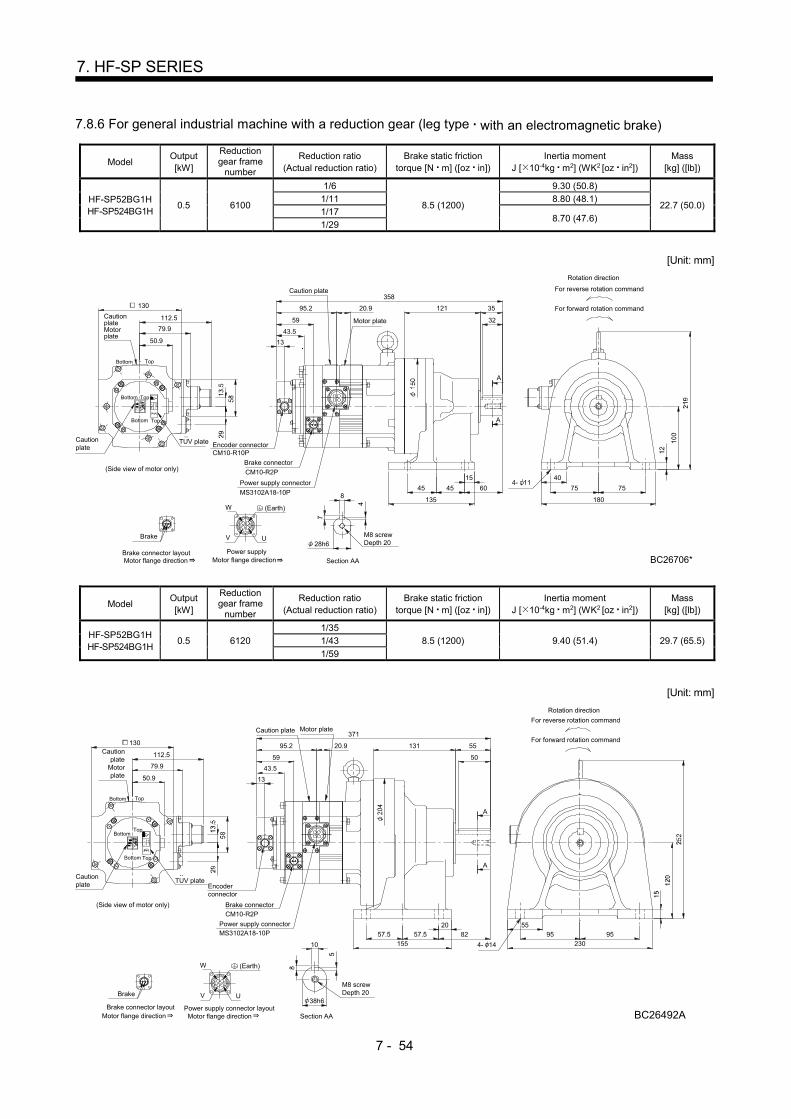
7 - 54
7. HF-SP SERIES
7.8.6 For general industrial machine with a reduction gear (leg type with an electromagnetic brake)
Model Output [kW]
Reduction gear frame
number
Reduction ratio (Actual reduction ratio)
Brake static friction torque [N m] ([oz in])
Inertia moment J [ 10-4kg m2] (WK2 [oz in2])
Mass [kg] ([lb])
HF-SP52BG1H HF-SP524BG1H
0.5 6100
1/6
8.5 (1200)
9.30 (50.8)
22.7 (50.0) 1/11 8.80 (48.1)
1/17 8.70 (47.6)
1/29
[Unit: mm]
Motor flange direction
V U
Power supply
B
W
CAD
(Side view of motor only)
50.9
112.5
130
13
59
358
Section AA
28h6M8 screwDepth 20
8
Encoder connectorCM10-R10P
Rotation direction
For forward rotation command
For reverse rotation command
Motor plate79.9
TUV plate
Power supply connector
MS3102A18-10P
CM10-R2P
Brake connector
Caution plate
95.2 20.9
Brake
Brake connector layoutMotor flange direction
Cautionplate
CautionplateMotorplate
40
75 75
BC26706*
180
4- 1115
45 45
135
60
121 35
32
A
A
43.5
(Earth)
Top
TopBottom
TopBottom
Bottom
Model Output [kW]
Reduction gear frame
number
Reduction ratio (Actual reduction ratio)
Brake static friction torque [N m] ([oz in])
Inertia moment J [ 10-4kg m2] (WK2 [oz in2])
Mass [kg] ([lb])
HF-SP52BG1H HF-SP524BG1H
0.5 6120 1/35
8.5 (1200) 9.40 (51.4) 29.7 (65.5) 1/43
1/59
[Unit: mm]
Motor flange direction
V U
Power supply connector layout
B
W
CAD
Section AA
38h6
10
For reverse rotation command
For forward rotation command
Rotation direction
M8 screwDepth 20
Cautionplate
Motorplate
95.2
Caution plate
Brake connectorCM10-R2P
MS3102A18-10PPower supply connector
TUV plate
79.9
Encoderconnector
59
13
130
112.5
50.9
(Side view of motor only)
Cautionplate
Motor plate
20.9
371
Motor flange directionBrake connector layout
Brake
55131
15557.5 57.5
2082 95
230
BC26492A
9555
A
A
50
4- 14
43.5
(Earth)
Bottom Top
BottomTop
TopBottom

7 - 55
7. HF-SP SERIES
Model Output [kW]
Reduction gear frame
number
Reduction ratio (Actual reduction ratio)
Brake static friction torque [N m] ([oz in])
Inertia moment J [ 10-4kg m2] (WK2 [oz in2])
Mass [kg] ([lb])
HF-SP102BG1H HF-SP1024BG1H
1.0 6120
1/6
8.5 (1200)
17.5 (95.7)
31.5 (69.4)
1/11 16.0 (87.5)
1/17 15.6 (85.3)
1/29 15.3 (83.7)
1/35
[Unit: mm]
Motor flange direction
V U
Power supply connector layout
B
W
CAD
(Side view of motor only)
50.9
112.5
130
13
59
393
EncoderconnectorCM10-R10P
79.9
TUV plate
Power supply connector
MS3102A18-10P
CM10-R2P
Brake connector
95.2
Brake
Brake connector layoutMotor flange direction
For reverse rotation command
For forward rotation command
Rotation direction
10
38h6
Section AA
M8 screwDepth 20
20.9
Caution plate
Motorplate
CautionplateMotorplate
Cautionplate
20
57.5 57.5 82
155
55
95 95
BC26707*
230
131 55
50
A
A
4- 14
43.5
(Earth)
TopBottom
TopBottom
TopBottom
Model Output [kW]
Reduction gear frame
number
Reduction ratio (Actual reduction ratio)
Brake static friction torque [N m] ([oz in])
Inertia moment J [ 10-4kg m2] (WK2 [oz in2])
Mass [kg] ([lb])
HF-SP102BG1H HF-SP1024BG1H
1.0 6130 1/43 8.5 (1200) 16.5 (90.2) 52.5 (116)
[Unit: mm]
Motor flange direction
V U
Power supply connector layout
B
W
CAD
Brake
Brake connector layoutMotor flange direction
95.2
Brake connectorCM10-R2P
MS3102A18-10PPower supply connector
TUV plate
79.9
EncoderconnectorCM10-R10P
446
59
13
112.5
50.9
(Side view of motor only)
130
For reverse rotation command
For forward rotation command
Rotation direction
50h6
14
Section AA
M10 screwDepth 18
20.9
Motorplate
Caution plate
CautionplateMotorplate
Cautionplate
170 70
56
65
145 145
BC26708*
330
25
72.5 72.5
195
100
4- 18
A
A
43.5
(Earth)
Bottom Top
BottomTop
BottomTop
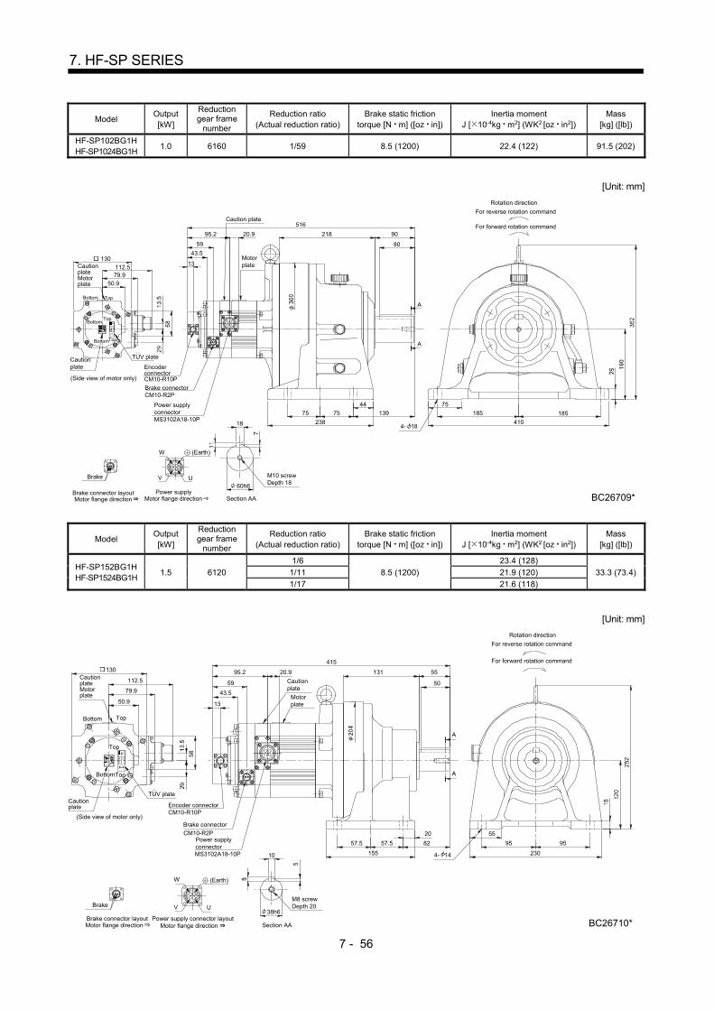
7 - 56
7. HF-SP SERIES
Model Output [kW]
Reduction gear frame
number
Reduction ratio (Actual reduction ratio)
Brake static friction torque [N m] ([oz in])
Inertia moment J [ 10-4kg m2] (WK2 [oz in2])
Mass [kg] ([lb])
HF-SP102BG1H HF-SP1024BG1H
1.0 6160 1/59 8.5 (1200) 22.4 (122) 91.5 (202)
[Unit: mm]
130
(Side view of motor only)
50.9
112.513
59
516
79.9
TUV plate
95.2
For reverse rotation command
For forward rotation command
Rotation direction
Motor flange directionBrake connector layout
Brake
DA
C
W
B
Power supply
UV
Motor flange direction
M10 screwDepth 1860h6
18
Section AA
20.9
EncoderconnectorCM10-R10P
Brake connectorCM10-R2P
Power supplyconnectorMS3102A18-10P
Caution plate
Motorplate
Cautionplate
CautionplateMotorplate
75
185 185
BC26709*
410
44
75 75 139
2384- 18
218 90
80
A
A
43.5
(Earth)
TopBottom
TopBottom
TopBottom
Model Output [kW]
Reduction gear frame
number
Reduction ratio (Actual reduction ratio)
Brake static friction torque [N m] ([oz in])
Inertia moment J [ 10-4kg m2] (WK2 [oz in2])
Mass [kg] ([lb])
HF-SP152BG1H HF-SP1524BG1H
1.5 6120
1/6
8.5 (1200)
23.4 (128)
33.3 (73.4) 1/11 21.9 (120)
1/17 21.6 (118)
[Unit: mm]
Motor flange direction
V U
Power supply connector layout
B
W
CAD
(Side view of motor only)
50.9
112.5
130
13
59
415
Encoder connectorCM10-R10P
79.9
TUV plate
Power supplyconnectorMS3102A18-10P
CM10-R2P
Brake connector
95.2
Brake
Brake connector layoutMotor flange direction
For reverse rotation command
For forward rotation command
Rotation direction
Section AA
38h6
10
M8 screwDepth 20
20.9
Motorplate
Cautionplate
Cautionplate
CautionplateMotorplate
131 55
50
A
A
20
57.5 57.5 82
155
55
95 95
BC26710*
2304- 14
43.5
(Earth)
Top
Top
TopBottom
Bottom

7 - 57
7. HF-SP SERIES
Model Output [kW]
Reduction gear frame
number
Reduction ratio (Actual reduction ratio)
Brake static friction torque [N m] ([oz in])
Inertia moment J [ 10-4kg m2] (WK2 [oz in2])
Mass [kg] ([lb])
HF-SP152BG1H HF-SP1524BG1H
1.5 6130 1/29
8.5 (1200) 22.6 (124)
54.3 (120) 1/35 22.5 (123)
[Unit: mm]
Motor flange direction
V U
Power supply connector layout
B
W
CAD
Brake
Brake connector layoutMotor flange direction
95.2
TUV plate
79.9
468
59
13
130
112.5
50.9
(Side view of motor only)
Rotation direction
For forward rotation command
For reverse rotation command
Section AA
M10 screwDepth 18
50h6
14
EncoderconnectorCM10-R10P
Brake connectorCM10-R2P
Power supply connectorMS3102A18-10P
Motorplate
Cautionplate
Cautionplate
CautionplateMotorplate
20.9 170 70
56
A
A
25
72.5 72.5 100
195
65
145 145
BC26711*
3304- 18
43.5
(Earth)
Bottom Top
BottomTop
TopBottom
Model Output [kW]
Reduction gear frame
number
Reduction ratio (Actual reduction ratio)
Brake static friction torque [N m] ([oz in])
Inertia moment J [ 10-4kg m2] (WK2 [oz in2])
Mass [kg] ([lb])
HF-SP152BG1H HF-SP1524BG1H
1.5 6160 1/43
8.5 (1200) 28.4 (155)
93.3 (206) 1/59 28.3 (155)
[Unit: mm]
V UPower supply
connector layout
W
Brake
Brake connector layoutMotor flange direction
Brake connectorCM10-R2P
EncoderconnectorCM10-R10P(Side view of motor only)
50.9
112.5
130 13
59
79.9
TUV plate
95.2
Power supply connectorMS3102A18-10P
M10 screwDepth 18
60h6
18
Section AA
For reverse rotation command
For forward rotation command
Rotation direction
20.9
Motorplate
Cautionplate
Cautionplate
CautionplateMotorplate
218 90
80
44
75 75 139
238
75
185 185
BC26712*
4104- 18
A
A
43.5
(Earth)
TopBottom
TopBottom
TopBottom
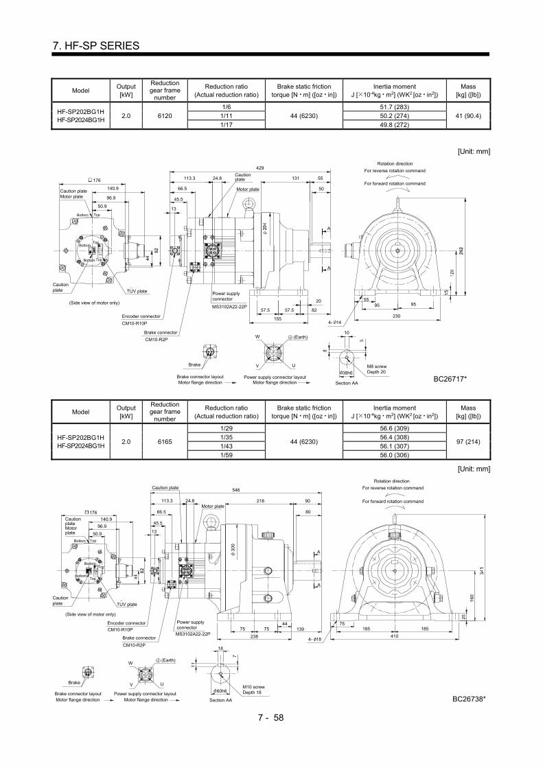
7 - 58
7. HF-SP SERIES
Model Output [kW]
Reduction gear frame
number
Reduction ratio (Actual reduction ratio)
Brake static friction torque [N m] ([oz in])
Inertia moment J [ 10-4kg m2] (WK2 [oz in2])
Mass [kg] ([lb])
HF-SP202BG1H HF-SP2024BG1H
2.0 6120
1/6
44 (6230)
51.7 (283)
41 (90.4) 1/11 50.2 (274)
1/17 49.8 (272)
[Unit: mm]
55
176
50.9
140.9
TUV plate
Cautionplate
(Side view of motor only)
Motor plate
Cautionplate 55
10
Section AA
38h6
ABC D
UV
W
Power supply connector layoutMotor flange direction
Brake
Brake connector layoutMotor flange direction
Encoder connector
Brake connector
CM10-R10P
CM10-R2P
Power supplyconnector
MS3102A22-22P
M8 screwDepth 20
113.3
13
131
429
8257.557.5
155
20
230
95 95
BC26717*
Caution plateMotor plate
4- 14
50
Bottom Top
BottomTop
Top
24.8
A
A
96.9
For reverse rotation command
For forward rotation command
Rotation direction
66.5
45.5
Bottom
(Earth)
Model Output [kW]
Reduction gear frame
number
Reduction ratio (Actual reduction ratio)
Brake static friction torque [N m] ([oz in])
Inertia moment J [ 10-4kg m2] (WK2 [oz in2])
Mass [kg] ([lb])
HF-SP202BG1H HF-SP2024BG1H
2.0 6165
1/29
44 (6230)
56.6 (309)
97 (214) 1/35 56.4 (308)
1/43 56.1 (307)
1/59 56.0 (306)
[Unit: mm]
Motor plate
Caution plate
ABC D
UV
W
Section AAMotor flange direction
Brake
Brake connector layoutMotor flange direction
Encoder connector
Brake connector
CM10-R10P
CM10-R2P
Power supplyconnector
MS3102A22-22P
113.3
13
M10 screwDepth 1860h6
18
A
A
238
75 7544
139
218 90
80
75
410
185
BC26738*
185
4- 18
546
Power supply connector layout
24.8
Top
TopBottom
CautionplateMotorplate
(Side view of motor only)
Cautionplate TUV plate
140.9
50.9
176
96.9
For reverse rotation command
For forward rotation command
Rotation direction
66.5
45.5
(Earth)
Bottom
TopBottom

7 - 59
7. HF-SP SERIES
Model Output [kW]
Reduction gear frame
number
Reduction ratio (Actual reduction ratio)
Brake static friction torque [N m] ([oz in])
Inertia moment J [ 10-4kg m2] (WK2 [oz in2])
Mass [kg] ([lb])
HF-SP352BG1H HF-SP3524BG1H
3.5 6135
1/6
44 (6230)
94.0 (514)
66 (146) 1/11 89.8 (491)
1/17 88.5 (484)
[Unit: mm]
Encoder connector
CM10-R10P
Power supplyconnector
MS3102A22-22P
113.3
13
Motor flange directionBrake connector layout
Brake
Motor flange directionPower supply connector layout
W
V U
DCB A
25
72.572.5
195
65
145 145
BC26730*
330
56
70170
519
Brake connector
CM10-R2P
A
A
For reverse rotation command
For forward rotation command
Rotation direction
100
4- 18
Caution plate
Motor plate
24.8
M10 screwDepth 1850h6
Section AA
14
Top
TopBottom
CautionplateMotorplate
(Side view of motor only)
Cautionplate TUV plate
140.9
50.9
176
96.966.5
45.5
(Earth)
Bottom
TopBottom
Model Output [kW]
Reduction gear frame
number
Reduction ratio (Actual reduction ratio)
Brake static friction torque [N m] ([oz in])
Inertia moment J [ 10-4kg m2] (WK2 [oz in2])
Mass [kg] ([lb])
HF-SP352BG1H HF-SP3524BG1H
3.5 6165 1/29
44 (6230) 93.6 (512)
104 (229) 1/35 93.3 (510)
[Unit: mm]
Encoder connector
Brake connector
CM10-R10P
CM10-R2P
Power supplyconnector
MS3102A22-22P
Motor flange directionBrake connector layout
Brake
Motor flange direction
Power supplyconnector layout
V U
DCB A M10 screw
Depth 1860h6
Section AA
18
113.3
13
A
A
4- 18
410
185
BC26733*
185
75
238
139
44
7575
80
90218
586
W
Caution plate
Motor plate
24.8
Top
TopBottom
CautionplateMotorplate
(Side view of motor only)
Cautionplate TUV plate
140.996.950.9
176
Rotation direction
For forward rotation command
For reverse rotation command
66.5
45.5
(Earth)
Bottom
TopBottom
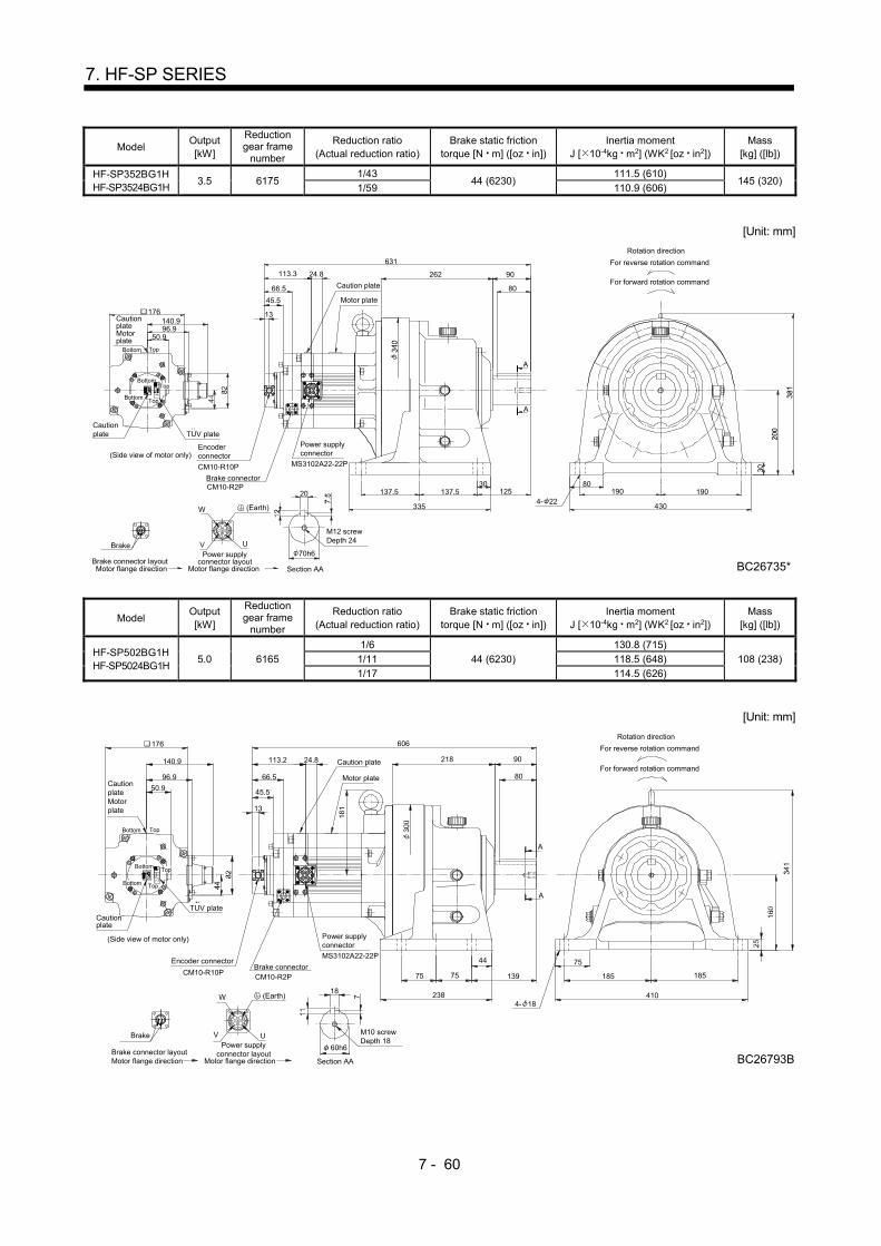
7 - 60
7. HF-SP SERIES
Model Output [kW]
Reduction gear frame
number
Reduction ratio (Actual reduction ratio)
Brake static friction torque [N m] ([oz in])
Inertia moment J [ 10-4kg m2] (WK2 [oz in2])
Mass [kg] ([lb])
HF-SP352BG1H HF-SP3524BG1H
3.5 6175 1/43
44 (6230) 111.5 (610)
145 (320) 1/59 110.9 (606)
[Unit: mm]
Encoderconnector
Brake connector
CM10-R10P
CM10-R2P
Motor flange directionBrake connector layout
Brake
Motor flange direction
Power supplyconnector layout
W
V U
DCB A
13
113.3
70h6
Section AA
20
262
137.5
335
137.5 190
430
BC26735*
30 80190
80
90
Power supplyconnector
MS3102A22-22P
4- 22
A
A
631
M12 screwDepth 24
Caution plate
Motor plate
125
24.8
Top
TopBottom
CautionplateMotorplate
(Side view of motor only)
Cautionplate TUV plate
140.9
50.9
176
96.9
66.5
Rotation direction
For forward rotation command
For reverse rotation command
45.5
(Earth)
Bottom
TopBottom
Model Output [kW]
Reduction gear frame
number
Reduction ratio (Actual reduction ratio)
Brake static friction torque [N m] ([oz in])
Inertia moment J [ 10-4kg m2] (WK2 [oz in2])
Mass [kg] ([lb])
HF-SP502BG1H HF-SP5024BG1H
5.0 6165
1/6
44 (6230)
130.8 (715)
108 (238) 1/11 118.5 (648)
1/17 114.5 (626)
[Unit: mm]
Encoder connectorBrake connector
CM10-R10PCM10-R2P
Power supplyconnector
MS3102A22-22P
Motor flange directionBrake connector layout
Brake
Motor flange direction
Power supplyconnector layout
V U
DCB A
M10 screwDepth 18
60h6
Section AA
18
113.2
13
4- 18W
24.8
Top
TopBottom
CautionplateMotorplate
(Side view of motor only)
Cautionplate
140.9
96.9
50.9
176
66.5
For reverse rotation command
For forward rotation command
Rotation direction
218 90
80
606
238
75 13975
44
A
A
75
410
185 185
BC26793B
Motor plate
Caution plate
TUV plate
45.5
(Earth)
Bottom
TopBottom
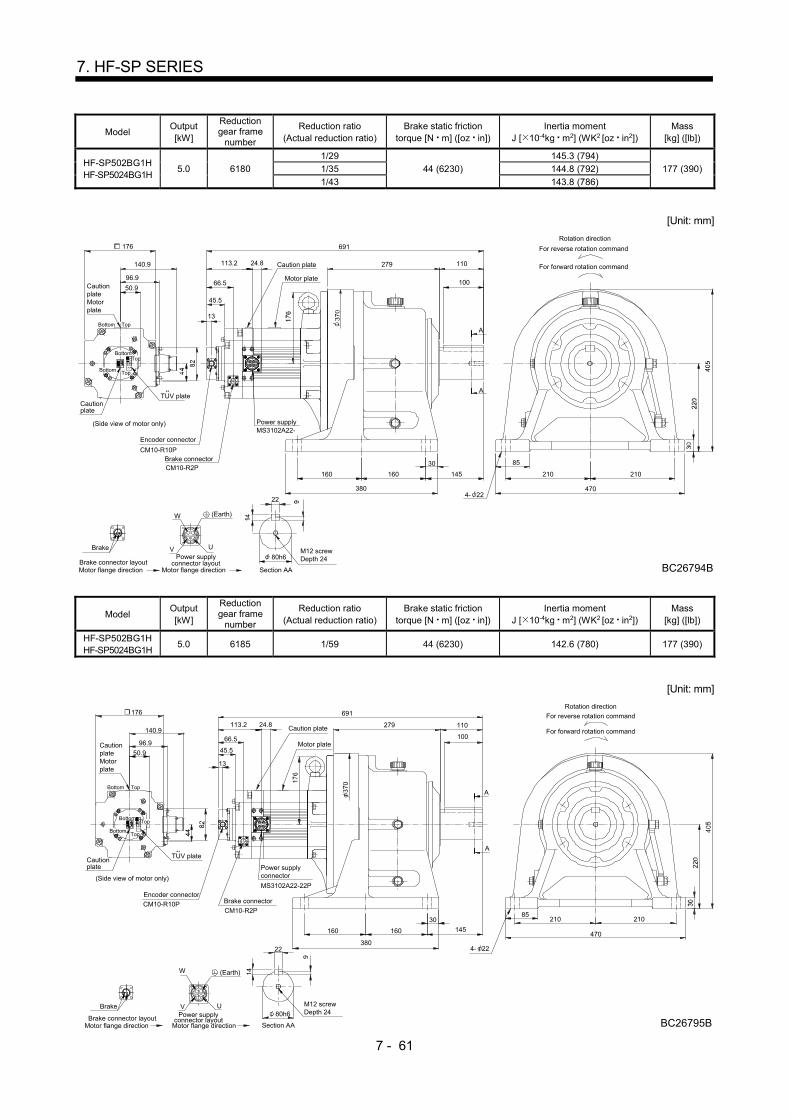
7 - 61
7. HF-SP SERIES
Model Output [kW]
Reduction gear frame
number
Reduction ratio (Actual reduction ratio)
Brake static friction torque [N m] ([oz in])
Inertia moment J [ 10-4kg m2] (WK2 [oz in2])
Mass [kg] ([lb])
HF-SP502BG1H HF-SP5024BG1H
5.0 6180
1/29
44 (6230)
145.3 (794)
177 (390) 1/35 144.8 (792)
1/43 143.8 (786)
[Unit: mm]
Encoder connector
Brake connectorCM10-R10P
CM10-R2P
Power supplyMS3102A22-
Motor flange directionBrake connector layout
Brake
Motor flange direction
Power supplyconnector layout
V U
DCB A
13
W
Caution plate
Motor plate
TopBottom
CautionplateMotorplate
(Side view of motor only)
Cautionplate
140.9
96.9
50.9
176
66.5
4- 22
Section AA
279 110
100
691
380
160 160
30
145
470
210
BC26794B
210
85
A
A
For reverse rotation command
For forward rotation command
Rotation direction
22
80h6M12 screwDepth 24
TUV plate
113.2 24.8
45.5
Top
(Earth)
Bottom
TopBottom
Model Output [kW]
Reduction gear frame
number
Reduction ratio (Actual reduction ratio)
Brake static friction torque [N m] ([oz in])
Inertia moment J [ 10-4kg m2] (WK2 [oz in2])
Mass [kg] ([lb])
HF-SP502BG1H HF-SP5024BG1H
5.0 6185 1/59 44 (6230) 142.6 (780) 177 (390)
[Unit: mm]
Motor flange directionBrake connector layout
Brake
Motor flange direction
Power supplyconnector layout
W
V U
DCB A
Rotation direction
For forward rotation command
For reverse rotation command
96.9
Cautionplate
176
140.9
50.9
Bottom Top
CautionplateMotorplate
(Side view of motor only)
Power supplyconnector
Brake connectorEncoder connector
CM10-R2PCM10-R10P
MS3102A22-22P
Caution plate
66.5
13
113.2
Motor plate
24.8
M12 screwDepth 2480h6
22
Section AA
210
BC26795B
470
21085
4- 22
160
380
160
30
691
279
145
100
110
A
A
TUV plate
45.5
Top
(Earth)
Bottom
TopBottom

7 - 62
7. HF-SP SERIES
Model Output [kW]
Reduction gear frame
number
Reduction ratio (Actual reduction ratio)
Brake static friction torque [N m] ([oz in])
Inertia moment J [ 10-4kg m2] (WK2 [oz in2])
Mass [kg] ([lb])
HF-SP702BG1H HF-SP7024BG1H
7.0 6165 1/6 44 (6230) 187.0 (1020) 117 (258)
[Unit: mm]
U
Motor flange directionPower supply connector layout
W
V
C
B
D
A
CautionplateMotorplate
96.9
149.1
176
(Side view of motor only)
Cautionplate
Section AA
Brake
Brake connector layoutMotor flange direction
TopBottom
50.9
185
BC26821A
410
80
13975
238
44
75
75
185
4- 18
A
A
For forward rotation command90218
Rotation direction
For reverse rotation command
66.5
121.2 32
666
Motor plate
13
Caution plate
MS3102A32-17PPower supply connector
Encoder connector
Brake connector
CM10-R2P
CM10-R10P
60h6
18
M10 screwDepth 18
TUV plate
45.5
(Earth)
TopBottom
Bottom Top
Model Output [kW]
Reduction gear frame
number
Reduction ratio (Actual reduction ratio)
Brake static friction torque [N m] ([oz in])
Inertia moment J [ 10-4kg m2] (WK2 [oz in2])
Mass [kg] ([lb])
HF-SP702BG1H HF-SP7024BG1H
7.0 6170 1/11
44 (6230) 199.9 (1090)
144 (317) 1/17 192.4 (1050)
[Unit: mm]
U
Motor flange direction
Power supplyconnector layout
W
V
C
B
D
A
A
A
90262
711
80
430
190 190
BC26806A
80
335
125137.5 137.5
30
20
M12 screwDepth 2470h6
For reverse rotation command
For forward rotation command
Rotation direction
CautionplateMotorplate
Caution plate
13
32121.2
66.596.9
149.1
176
CM10-R2P
Brake connector
Encoder connector
(Side view of motor only)
Cautionplate
CM10-R10P
Motor plate
Power supply connector
MS3102A32-17P
4- 22
Section AA
Brake
Brake connector layoutMotor flange direction
TopBottom
Top
50.9
TUV plate
45.5
(Earth)
Bottom
Bottom Top
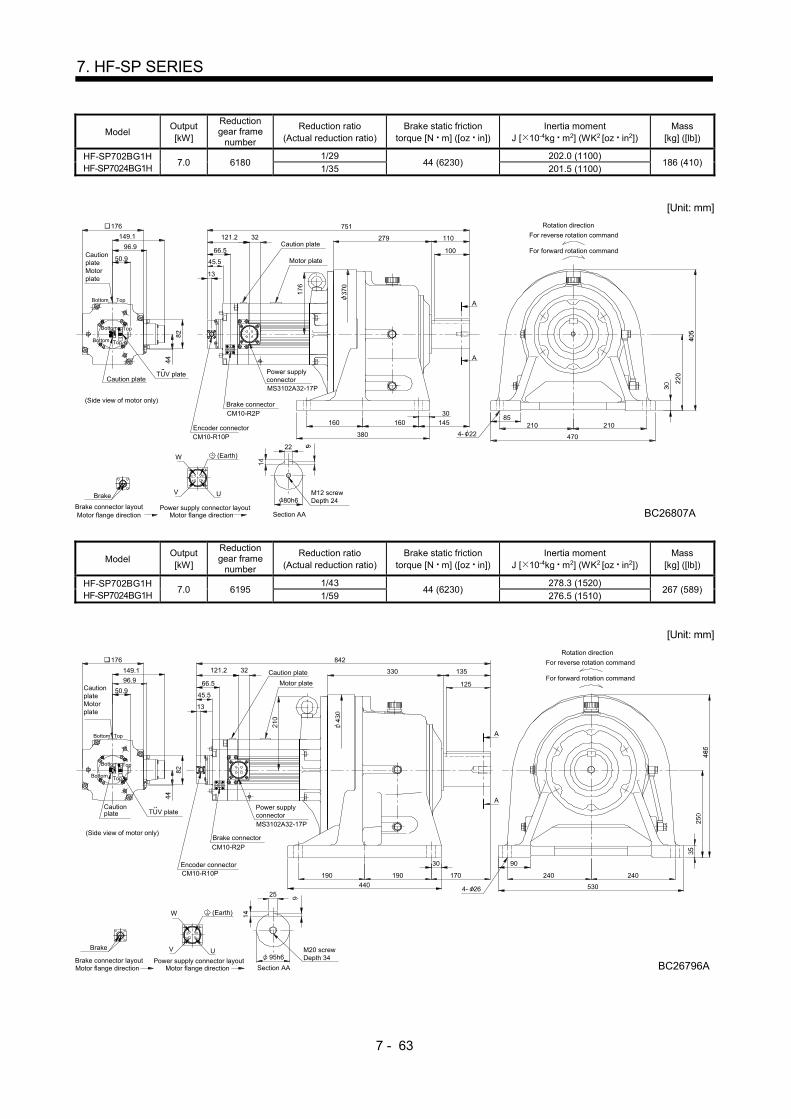
7 - 63
7. HF-SP SERIES
Model Output [kW]
Reduction gear frame
number
Reduction ratio (Actual reduction ratio)
Brake static friction torque [N m] ([oz in])
Inertia moment J [ 10-4kg m2] (WK2 [oz in2])
Mass [kg] ([lb])
HF-SP702BG1H HF-SP7024BG1H
7.0 6180 1/29
44 (6230) 202.0 (1100)
186 (410) 1/35 201.5 (1100)
[Unit: mm]
Motor flange directionBrake connector layout
Brake
149.1
96.9 66.5
121.2 32
Power supply connector layoutMotor flange direction
AB
C D
UV
W
13
Caution plate
Motor plateCautionplateMotorplate
176
(Side view of motor only)
Caution plateMS3102A32-17P
Power supplyconnector
Encoder connectorCM10-R10P
Brake connectorCM10-R2P
160
380
160
100
110
145
279
4704- 22210
85210
BC26807A
Rotation direction
For forward rotation command
For reverse rotation command751
30
A
A
TopBottom
Top
22
80h6M12 screwDepth 24
50.9
Section AA
TUV plate
45.5
(Earth)
Bottom
Bottom
Top
Model Output [kW]
Reduction gear frame
number
Reduction ratio (Actual reduction ratio)
Brake static friction torque [N m] ([oz in])
Inertia moment J [ 10-4kg m2] (WK2 [oz in2])
Mass [kg] ([lb])
HF-SP702BG1H HF-SP7024BG1H
7.0 6195 1/43
44 (6230) 278.3 (1520)
267 (589) 1/59 276.5 (1510)
[Unit: mm]
Motor flange directionBrake connector layout
Brake
149.1
96.9 66.5
121.2 32 135330
842
170
440
190 190
30
530
240 240
BC26796A
90
4- 2625
95h6M20 screwDepth 34Power supply connector layout
Motor flange direction
AB
C D
UV
W
125
13
Caution plate
Motor plateCautionplateMotorplate
176
(Side view of motor only)
Cautionplate
MS3102A32-17P
Power supplyconnector
Encoder connectorCM10-R10P
Brake connector
CM10-R2P
A
A
Rotation direction
For forward rotation command
For reverse rotation command
TopBottom
Top
Section AA
50.9
Bottom
TUV plate
45.5
(Earth)
Bottom
Top
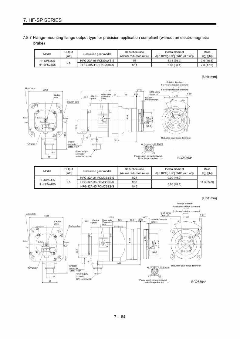
7 - 64
7. HF-SP SERIES
7.8.7 Flange-mounting flange output type for precision application compliant (without an electromagnetic
brake)
Model Output
[kW] Reduction gear model
Reduction ratio
(Actual reduction ratio)
Inertia moment
J [ 10-4kg m2] (WK2 [oz in2])
Mass
[kg] ([lb])
HF-SP52G5
HF-SP524G5 0.5
HPG-20A-05-FOKSAWS-S 1/5 6.75 (36.9) 7.6 (16.8)
HPG-20A-11-FOKSAXS-S 1/11 6.66 (36.4) 7.8 (17.2)
[Unit: mm]
U
W
V
C
B
D
A
Cautionplate
Motor plate
Cautionplate
Motor plate(Oppositeside)
EncoderconnectorCM10-R10P
13
38.2
130
TUV plate
Caution plate
13.5
58
Power supplyconnectorMS3102A18-10P
30
105
45
6-M6 screwDepth 10
5( 24H7effective range)
4- 9
152.8
25
C0.5
60 10 8
+0.4-0.527213.5
90
45
(Earth)
Top Top
Top
Top
Bottom Bottom
Bottom
Bottom
Top
Motor flange directionPower supply connector layout
Reduction gear flange dimension
BC26593*
For reverse rotation command
For forward rotation command
Rotation direction
Bottom
Model Output
[kW] Reduction gear model
Reduction ratio
(Actual reduction ratio)
Inertia moment
J [ 10-4kg m2] (WK2 [oz in2])
Mass
[kg] ([lb])
HF-SP52G5
HF-SP524G5 0.5
HPG-32A-21-FOMCSYS-S 1/21 9.00 (49.2)
11.3 (24.9) HPG-32A-33-FOMCSZS-S 1/33 8.80 (48.1)
HPG-32A-45-FOMCSZS-S 1/45
[Unit: mm]
U
W
V
C
B
D
A
Cautionplate
Motor plate
Cautionplate
Motor plate(Oppositeside)
EncoderconnectorCM10-R10P
13
38.2
130
TUV plate
Caution plate
13.5
58
Power supplyconnector
MS3102A18-10P
60
135
4530
4- 11120
39.5
164.8
54.5
C0.5
5( 32H7effectiverange)
6-M8 screwDepth 12
13 13225.5
(Earth)
Top Top
Top
BottomTop
Bottom Bottom Bottom
Motor flange directionPower supply connector layout
Reduction gear flange dimension
BC26594*
For forward rotation command
For reverse rotation command
Rotation direction
+0.4-0.535
Bottom
Top
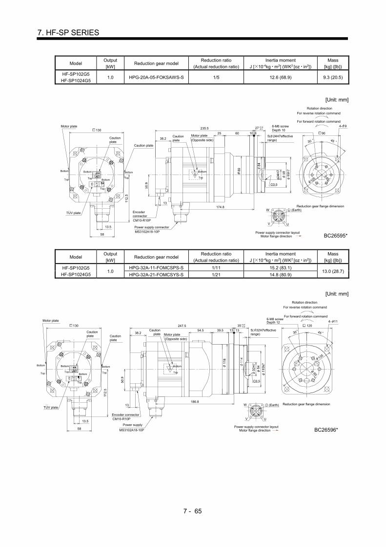
7 - 65
7. HF-SP SERIES
Model Output
[kW] Reduction gear model
Reduction ratio
(Actual reduction ratio)
Inertia moment
J [ 10-4kg m2] (WK2 [oz in2])
Mass
[kg] ([lb])
HF-SP102G5
HF-SP1024G5 1.0 HPG-20A-05-FOKSAWS-S 1/5 12.6 (68.9) 9.3 (20.5)
[Unit: mm]
U
W
V
CB
DA
Caution plate
38.2Cautionplate
Motor plate(Opposite side)
Cautionplate
Motor plate130
EncoderconnectorCM10-R10P
13
MS3102A18-10PPower supply connector
58
13.5
235.5
60
174.8
25
30
105
45
C0.5
6-M6 screwDepth 10
5( 24H7effectiverange)
8 90
45
4- 9
10
(Earth)TUV plate
Bottom
TopTop Top
Top
BottomTop
Bottom Bottom Bottom
Motor flange directionPower supply connector layout
Reduction gear flange dimension
BC26595*
For reverse rotation command
For forward rotation command
Rotation direction
+0.4-0.527
Model Output
[kW] Reduction gear model
Reduction ratio
(Actual reduction ratio)
Inertia moment
J [ 10-4kg m2] (WK2 [oz in2])
Mass
[kg] ([lb])
HF-SP102G5
HF-SP1024G5 1.0
HPG-32A-11-FOMCSPS-S 1/11 15.2 (83.1) 13.0 (28.7)
HPG-32A-21-FOMCSYS-S 1/21 14.8 (80.9)
[Unit: mm]
U
W
V
C
B
D
A
Cautionplate
38.2Caution
plate Motor plate(Opposite side)
Cautionplate
Motor plate
TUV plate
Encoder connectorCM10-R10P
MS3102A18-10P
Power supply58
13.5
39.5
186.8
247.554.5
60
135
4530
C0.5
4- 11
5( 32H7effectiverange)
6-M8 screwDepth 12
120
13
130
13 13
(Earth)
Bottom
TopTopTop
Top
Bottom Top
Bottom Bottom Bottom
Motor flange directionPower supply connector layout
Reduction gear flange dimension
BC26596*
For reverse rotation command
For forward rotation command
Rotation direction
+0.4-0.535

7 - 66
7. HF-SP SERIES
Model Output
[kW] Reduction gear model
Reduction ratio
(Actual reduction ratio)
Inertia moment
J [ 10-4kg m2] (WK2 [oz in2])
Mass
[kg] ([lb])
HF-SP102G5
HF-SP1024G5 1.0
HPG-50A-33-FOAABC-S 1/33 16.6 (90.8) 22.5 (49.6)
HPG-50A-45-FOAABC-S 1/45 16.5 (90.2)
[Unit: mm]
107
202.8
263.5
UCM10-R10P
Encoderconnector
58
TUV plate
Power supply connector
MS3102A18-10P
W
V
BC
AD
Cautionplate
Motor plate
38.2
Cautionplate Caution
plate
Motor plate(Oppositeside)
190
C0.5
170
100
7( 47H7effectiverange)
1316
22.5
14-M8 screwDepth 12 4- 14
130
13.5
13
22.5 45
6 2
2.5
(
135
)
(Earth)
Power supply connector layoutMotor flange direction
Top
Top Top
Bottom
BottomTop
Reduction gear flange dimension
BC26597*
For reverse rotation command
For forward rotation command
Rotation direction
Top
+0.5-0.853
BottomBottomBottom
Model Output
[kW] Reduction gear model
Reduction ratio
(Actual reduction ratio)
Inertia moment
J [ 10-4kg m2] (WK2 [oz in2])
Mass
[kg] ([lb])
HF-SP152G5
HF-SP1524G5 1.5 HPG-20A-05-FOKSAWS-S 1/5 18.5 (101) 11.1 (24.5)
[Unit: mm]
U
W
V
C
B
D
A
38.2Cautionplate
Cautionplate
58
13.5
TUV plate
CM10-R10PEncoder connector
Power supplyconnector
MS3102A18-10P
Motor plate(Opposite side)
Cautionplate
130Motor plate
257.5
60
196.8
25
105C0.5
4- 9
8 90
45
6-M6 screwDepth 10
30 45
105( 24H7effectiverange)
13
(Earth)
Top Top
Top
BottomTop
Bottom Bottom Bottom
Power supply connector layoutMotor flange direction
Reduction gear flange dimension
BC26598*
For reverse rotation command
For forward rotation command
Rotation direction
+0.4-0.527
Bottom
Top

7 - 67
7. HF-SP SERIES
Model Output
[kW] Reduction gear model
Reduction ratio
(Actual reduction ratio)
Inertia moment
J [ 10-4kg m2] (WK2 [oz in2])
Mass
[kg] ([lb])
HF-SP152G5
HF-SP1524G5 1.5 HPG-32A-11-FOMCSPS-S 1/11 21.1 (115) 14.8 (32.6)
[Unit: mm]
U
W
V
C
B
D
A
38.2Cautionplate
Cautionplate
58
13.5
TUV plate
Encoder connector
13
Power supplyconnectorMS3102A18-10P
CM10-R10P
Motor plate
(Opposite side)
Cautionplate
130Motor plate
208.8
269.554.5
60135
4530
C0.5
120
5( 32H7effectiverange)
39.5
6-M8 screwDepth 12 4- 11
13 13
Bottom
TopTop
Top
Top
Bottom Top
BottomBottom Bottom
Power supply connector layoutMotor flange direction
Reduction gear flange dimension
BC26599*
For forward rotation command
For reverse rotation command
Rotation direction
(Earth)
+0.4-0.535
Model Output
[kW] Reduction gear model
Reduction ratio
(Actual reduction ratio)
Inertia moment
J [ 10-4kg m2] (WK2 [oz in2])
Mass
[kg] ([lb])
HF-SP152G5
HF-SP1524G5 1.5
HPG-50A-21-FOAABC-S 1/21 23.5 (128)
24.3 (53.6) HPG-50A-33-FOAABC-S 1/33 22.5 (123)
HPG-50A-45-FOAABC-S 1/45 22.4 (122)
[Unit: mm]
190
45
14-M8 screwDepth 12
170
100
7( 47H7effectiverange)
22.5
4- 14
107
224.8
285.5
Encoderconnector
CM10-R10P
Power supply connector
V U
WBC
AD
38.2
Cautionplate Caution
plate Motor plate
(Opposite side)
C0.5
1316
58
TUV plate13.5
MS3102A18-10P
Cautionplate
Motor plate
13
130
22.5
6 2
2.5
(
135
)
(Earth)
Reduction gear flange dimension
BC26600*
For forward rotation command
For reverse rotation command
Rotation direction
Top
Bottom
Top
Bottom
Top
Motor flange directionPower supply connector layout
Top
Bottom
Top
Bottom
Bottom
+0.5-0.853
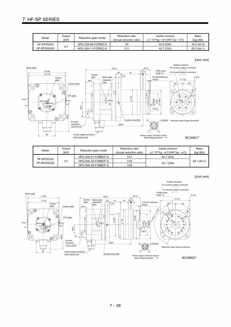
7 - 68
7. HF-SP SERIES
Model Output
[kW] Reduction gear model
Reduction ratio
(Actual reduction ratio)
Inertia moment
J [ 10-4kg m2] (WK2 [oz in2])
Mass
[kg] ([lb])
HF-SP202G5
HF-SP2024G5 2.0
HPG-32A-05-FOPBZI-S 1/5 42.9 (235) 19.5 (43.0)
HPG-32A-11-FOPBZJ-S 1/11 42.7 (233) 20.0 (44.1)
[Unit: mm]
Cautionplate
WEyebolt hole (M8)
BC26601*
13
TUV plate
Cautionplate
Motor plate
(Oppositeside)
UV
CB
D
A
Motor plate
CM10-R10P
Encoderconnector
MS3102A22-22P
Power supply connector82
38.5
208.8
30
C0.5
45
135
4- 11120
60
6-M8 screwDepth 12
272.5
9125176
180
12.5
13 13
Caution plate
+0.4-0.535
5( 32H7effectiverange)
(Earth)
Top
Top
Bottom
Bottom Top
BottomBottom
Top
Power supply connector layoutMotor flange direction
Reduction gear flange dimension
For reverse rotation command
For forward rotation command
Rotation direction
Bottom
Top
Model Output
[kW] Reduction gear model
Reduction ratio
(Actual reduction ratio)
Inertia moment
J [ 10-4kg m2] (WK2 [oz in2])
Mass
[kg] ([lb])
HF-SP202G5
HF-SP2024G5 2.0
HPG-50A-21-FOBBDF-S 1/21 44.7 (244)
29.1 (64.2) HPG-50A-33-FOBBDF-S 1/33 43.7 (239)
HPG-50A-45-FOBBDF-S 1/45
[Unit: mm]
63
292.5
228.8
4522.5
190
170
100
7( 47H7 effectiverange)
C0.5
45
22.5
14-M8 screwDepth 12
13
82 Power supply connector
MS3102A22-22P
V
BC
U
AD
Encoderconnector
CM10-R10PW
176
Motor plate
Cautionplate
Cautionplate
38.5
TUV plate
(Oppositeside)
Motor plate 25
180
16 13
12.5
4- 14
Caution plate
+0.5-0.853
6 2
2.5
(
135
)
(Earth)
For forward rotation command
For reverse rotation command
Rotation direction
Motor flange directionPower supply connector layout
Top
Bottom Bottom
Top
Top
Bottom
Bottom
Top
Reduction gear flange dimension
BC26602*
Bottom
Top
Eyebolt hole (M8)
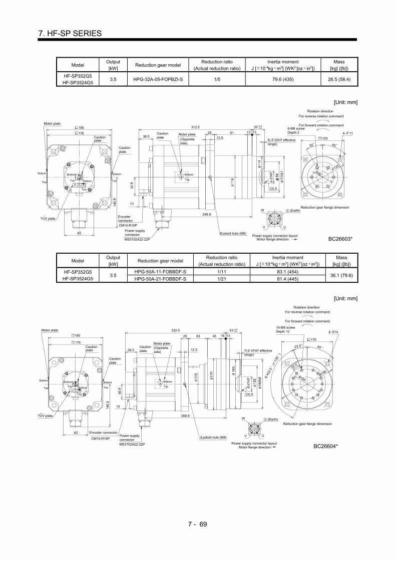
7 - 69
7. HF-SP SERIES
Model Output
[kW] Reduction gear model
Reduction ratio
(Actual reduction ratio)
Inertia moment
J [ 10-4kg m2] (WK2 [oz in2])
Mass
[kg] ([lb])
HF-SP352G5
HF-SP3524G5 3.5 HPG-32A-05-FOPBZI-S 1/5 79.6 (435) 26.5 (58.4)
[Unit: mm]
W
Power supplyconnector
DA
BC26603*
UV
BC
MS3102A22-22P
Encoderconnector
CM10-R10P
Cautionplate
Motor plate
(Oppositeside)
38.5176
Motor plate
82
Cautionplate
Cautionplate
13
TUV plate
30 45
135
1205( 32H7 effectiverange)
60
6-M8 screwDepth 2 4- 11
248.8
9125
C0.5
13 13
312.5180
12.5
(Earth)
Top
Bottom
Top
Bottom
Bottom
Top
Top
Bottom
Power supply connector layoutMotor flange direction
Reduction gear flange dimension
Rotation direction
For forward rotation command
For reverse rotation command
Eyebolt hole (M8)
+0.4-0.535
Top
Bottom
Model Output
[kW] Reduction gear model
Reduction ratio
(Actual reduction ratio)
Inertia moment
J [ 10-4kg m2] (WK2 [oz in2])
Mass
[kg] ([lb])
HF-SP352G5
HF-SP3524G5 3.5
HPG-50A-11-FOBBDF-S 1/11 83.1 (454) 36.1 (79.6)
HPG-50A-21-FOBBDF-S 1/21 81.4 (445)
[Unit: mm]
268.8TUV plate
13
MS3102A22-22P
CM10-R10P
Encoder connectorPower supplyconnector
V U
CB A
D
W
176
Motor plate
Cautionplate
Cautionplate
Cautionplate
38.5
Motor plate(Oppositeside)
4522.5
190
170
100
7( 47H7 effectiverange)
C0.5
45
22.5
14-M8 screwDepth 12
BC26604*
4- 14180
332.5
25 63 16 13
12.5
82
+0.5-0.853
Eyebolt hole (M8)
6 2
2.5
(
135
)
(Earth)
Motor flange directionPower supply connector layout
Top
Bottom Bottom
Top
Top
Bottom
Bottom
Top
Reduction gear flange dimension
For forward rotation command
For reverse rotation commandRotation direction
Bottom
Top
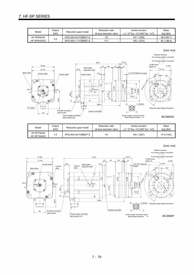
7 - 70
7. HF-SP SERIES
Model Output
[kW] Reduction gear model
Reduction ratio
(Actual reduction ratio)
Inertia moment
J [ 10-4kg m2] (WK2 [oz in2])
Mass
[kg] ([lb])
HF-SP502G5
HF-SP5024G5 5.0
HPG-50A-05-FOBBCF-S 1/5 107.1 (586) 38.6 (85.1)
HPG-50A-11-FOBBDF-S 1/11 105.1 (575) 40.1 (88.4)
[Unit: mm]
13
288.8
352.5
63
12.5
25
C0.5
53 +0.5-0.8
131645
82
TUV plate
38.5
BC26605C
100
Encoder connector
Power supply connector
AB
V U
MS3102A22-22P
CM10-R10P
W
C D
Motor plate Caution plate Caution plate
Motor plate
(Opposite side)
190
170
14-M8 screwDepth 12 4- 14
7( 47H7effective range)
180
176
Caution plate
Eyebolt hole (M8)
6 2
2.5
(
135
)
(Earth)
Motor flange directionPower supply connector layout
Top
Bottom
Top
BottomTop
Bottom
Reduction gear flange dimension
For forward rotation command
Rotation direction
For reverse rotation command
Top
Bottom
Top
Bottom
45
22.5
22.5
Model Output
[kW] Reduction gear model
Reduction ratio
(Actual reduction ratio)
Inertia moment
J [ 10-4kg m2] (WK2 [oz in2])
Mass
[kg] ([lb])
HF-SP702G5
HF-SP7024G5 7.0 HPG-50A-05-FOBBCF-S 1/5 164.1 (897) 47.6 (105)
[Unit: mm]
13
Encoder connector
CM10-R10P
CautionplateMotor plate
Caution plateCautionplate
38.5 Motor plate(Opposite side)
340.8
412.5
4525 63
12.5
22.5 45
100
190
C0.5
14-M8 screwDepth 1216 13
7( 47H7 effectiverange)
170
22.5
4- 14
UV
W
CB
DA
180
MS3102A32-17P
Power supply connector
176
82
6 2
2.5
(
135
)
(Earth)
Top
Bottom
TopBottom
Top
Bottom
Reduction gear flange dimension
BC26606*
For forward rotation command
For reverse rotation command
Rotation direction
Motor flange directionPower supply connector layout
Eyebolt hole (M8)
+0.5-0.853
Bottom
Top

7 - 71
7. HF-SP SERIES
7.8.8 Flange-mounting flange output type for precision application compliant (with an electromagnetic brake)
Model Output [kW]
Reduction gear model Reduction ratio
(Actual reduction ratio)
Brake static friction torque
[N m] ([oz in])
Inertia moment J [ 10-4kg m2] (WK2 [oz in2])
Mass [kg] ([lb])
HF-SP52BG5 HF-SP524BG5
0.5 HPG-20A-05-FOKSAWS-S 1/5
8.5 (1200) 8.95 (48.9) 9.5 (20.9)
HPG-20A-11-FOKSAXS-S 1/11 8.86 (48.4) 9.7 (21.4)
[Unit: mm]
Motor plate
(Oppositeside)
Cautionplate
V U
B
W
C
A
D
Motor plate
Cautionplate
13.5
58
TUV plate
Cautionplate
130
29Brake
CM10-R2PCM10-R10P
Brake connector
59
Encoderconnector
13
43.5
MS3102A18-10P
Power supplyconnector
60
152.8
248
25
105
C0.5
6-M6 screwDepth 10
810
5( 24H7 effectiverange)
90
45
4530
4- 9
Bottom
Top Bottom
Top
Bottom
Top
Power supply connector layout
Top
Motor flange direction
Top
Bottom
Motor flange directionBrake connector layout
Reduction gear flange dimension
BC26607*
For reverse rotation command
For forward rotation command
Rotation direction
+0.4-0.527
(Earth)
Bottom
Model Output [kW]
Reduction gear model Reduction ratio
(Actual reduction ratio)
Brake static friction torque
[N m] ([oz in])
Inertia moment J [ 10-4kg m2] (WK2 [oz in2])
Mass [kg] ([lb])
HF-SP52BG5 HF-SP524BG5
0.5
HPG-32A-21-FOMCSYS-S 1/21
8.5 (1200)
11.2 (61.2)
13.2 (29.1) HPG-32A-33-FOMCSZS-S 1/33 11.0 (60.1)
HPG-32A-45-FOMCSZS-S 1/45
[Unit: mm]
Motor plate(Oppositeside)
Cautionplate
V U
B
W
CAD
Motor plate 260
Cautionplate
60
135
4530
6-M8 screwDepth 12
1204- 11
5( 32H7 effectiverange)
1313
C0.5
39.554.5
13.5
58
TUV plate
Caution plate
130
164.8
29BrakeCM10-R2P
CM10-R10P
Brake connector
59
Encoder connector
13
43.5
MS3102A18-10PPower supply connector
+0.4-0.535
(Earth)
Bottom
TopBottom
Top
Bottom
Top
Power supply connector layout
Top
Motor flange direction
Top
Bottom
Reduction gear flange dimension
BC26495*
For forward rotation command
For reverse rotation command
Rotation direction
Motor flange directionBrake connector layout
Bottom

7 - 72
7. HF-SP SERIES
Model Output [kW]
Reduction gear model Reduction ratio
(Actual reduction ratio)
Brake static friction torque
[N m] ([oz in])
Inertia moment J [ 10-4kg m2] (WK2 [oz in2])
Mass [kg] ([lb])
HF-SP102BG5 HF-SP1024BG5
1.0 HPG-20A-05-FOKSAWS-S 1/5 8.5 (1200) 14.7 (80.4) 11.3 (24.9)
[Unit: mm]
59
W
V
D
U
B AC
43.5Cautionplate
Motor plate
Cautionplate
TUV plate
130
Power supplyconnectorMS3102A18-10P
13
CM10-R2P
Brake connector
Caution plate Motor plate
(Oppositeside)
Brake29 13.5CM10-R10P
Encoder connector
270
174.8
6025
30
105
45
C0.5
6-M6 screwDepth 10
5( 24H7 effectiverange)
90
45
4- 9
10 8
58
(Earth)
+0.4-0.527
Top
Bottom
Top
Bottom
TopBottom
Bottom
Top
Motor flange directionBrake connector layout Power supply connector layout
Motor flange direction
Reduction gear flange dimension
BC26609*
For reverse rotation command
For forward rotation command
Rotation direction
Top
Bottom
Model Output [kW]
Reduction gear model Reduction ratio
(Actual reduction ratio)
Brake static friction torque
[N m] ([oz in])
Inertia moment J [ 10-4kg m2] (WK2 [oz in2])
Mass [kg] ([lb])
HF-SP102BG5 HF-SP1024BG5
1.0 HPG-32A-11-FOMCSPS-S 1/11
8.5 (1200) 17.3 (94.6)
15.0 (33.1) HPG-32A-21-FOMCSYS-S 1/21 16.9 (92.4)
[Unit: mm]
59 W
V
D
U
B AC
43.5
Cautionplate
Motor plate
Cautionplate
TUV plate
Power supplyconnectorMS3102A18-10P
13
CM10-R2P
Brake connector
Cautionplate Motor plate
(Opposite side)
Brake29 13.5
CM10-R10P
Encoderconnector
282
186.8
54.5
60
135
4530
C0.5
120
5( 32H7 effectiverange)
39.5 13 13
6-M8 screwDepth 12 4- 11
130
58
(Earth)
Top
Bottom
Top
Bottom
TopBottom
Bottom
Top
Motor flange directionBrake connector layout Power supply connector layout
Motor flange direction
Reduction gear flange dimension
BC26610*
Rotation direction
For reverse rotation command
For forward rotation command
Top
Bottom
+0.4-0.535

7 - 73
7. HF-SP SERIES
Model Output [kW]
Reduction gear model Reduction ratio
(Actual reduction ratio)
Brake static friction torque
[N m] ([oz in])
Inertia moment J [ 10-4kg m2] (WK2 [oz in2])
Mass [kg] ([lb])
HF-SP102BG5 HF-SP1024BG5
1.0 HPG-50A-33-FOAABC-S 1/33
8.5 (1200) 18.7 (102)
24.5 (54.0) HPG-50A-45-FOAABC-S 1/45 18.6 (102)
[Unit: mm]
107
298
Brake
MS3102A18-10P
Power supply connector
Cautionplate Motor plate
(Oppositeside)
45
190
22.5
W
UV
CB A
D
14-M8 screwDepth 12
17016 13
C0.5
4- 14
100
13
59
Encoderconnector
CM10-R10P
Brake connector
CM10-R2P
Cautionplate
43.5
TUV plate
29 13.5
Motor plate
Cautionplate
22.5
130
202.8
7( 47H7 effectiverange)
58
+0.5-0.853
6 2
2.5
(
135
)
(Earth)
Brake connector layoutMotor flange direction Motor flange direction
Power supply connector layout
Reduction gear flange dimension
BC26611*
TopTop
Bottom
Top
BottomTop
For reverse rotation command
For forward rotation command
Rotation direction
Top
BottomBottom Bottom
Model Output [kW]
Reduction gear model Reduction ratio
(Actual reduction ratio)
Brake static friction torque
[N m] ([oz in])
Inertia moment J [ 10-4kg m2] (WK2 [oz in2])
Mass [kg] ([lb])
HF-SP152BG5 HF-SP1524BG5
1.5 HPG-20A-05-FOKSAWS-S 1/5 8.5 (1200) 20.7 (113) 13.1 (28.9)
[Unit: mm]
W
Brake V
CB
U
D
A
Cautionplate
Cautionplate
Motor plate 130
TUV plate
13.529
13
59
EncoderconnectorCM10-R10P
Brake connectorCM10-R2P
Power supply connector
MS3102A18-10P
43.5(Opposite side)Motor plate
Caution plate
292
196.8
6025
30
C0.5105
5( 24H7effectiverange)
810 90
45
6-M6 screwDepth 10
4- 9
45
58
+0.4-0.527
(Earth)
Top
Top
Bottom
Top
Bottom
Brake connector layoutMotor flange direction
Bottom Top
Bottom
Power supply connector layoutMotor flange direction
Reduction gear flange dimension
BC26612*
For reverse rotation command
For forward rotation command
Rotation direction
Top
Bottom
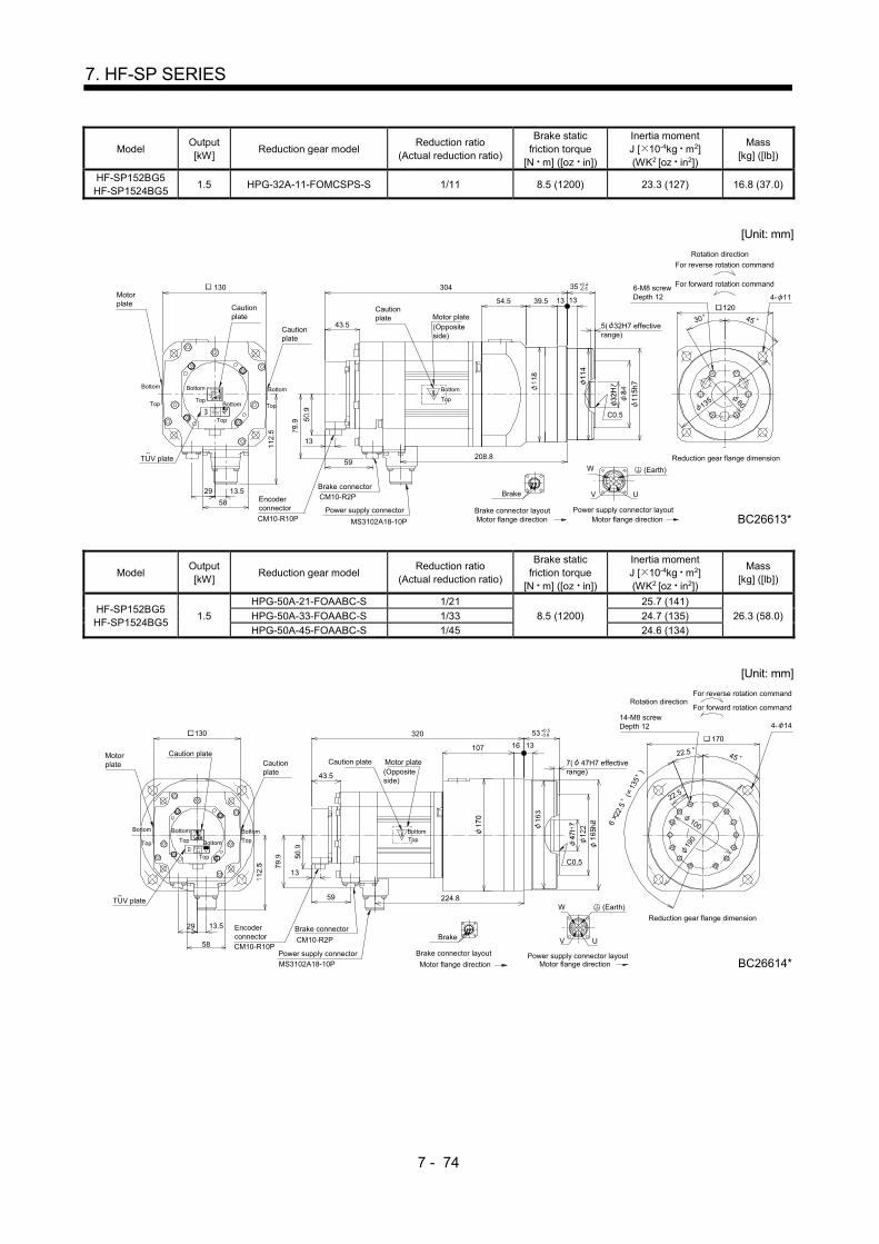
7 - 74
7. HF-SP SERIES
Model Output [kW]
Reduction gear model Reduction ratio
(Actual reduction ratio)
Brake static friction torque
[N m] ([oz in])
Inertia moment J [ 10-4kg m2] (WK2 [oz in2])
Mass [kg] ([lb])
HF-SP152BG5 HF-SP1524BG5
1.5 HPG-32A-11-FOMCSPS-S 1/11 8.5 (1200) 23.3 (127) 16.8 (37.0)
[Unit: mm]
54.5
208.8
304
W
V
59
MS3102A18-10P
Power supply connector
Brake connectorBrake
Cautionplate
43.5Motor plate(Oppositeside)
30 45
DC
U
B A
120
135
5( 32H7 effectiverange)
C0.5
1339.5 13
60
6-M8 screwDepth 12 4- 11
13
TUV plate
CM10-R10P
Encoderconnector
29 13.5CM10-R2P
Cautionplate
Motorplate
130
Cautionplate
58
+0.4-0.535
(Earth)
Motor flange directionPower supply connector layout
Motor flange directionBrake connector layout
Reduction gear flange dimension
BC26613*
Rotation direction
For reverse rotation command
For forward rotation command
Bottom
TopTop
Bottom
Top
Bottom Top
Bottom
Top
Bottom
Model Output [kW]
Reduction gear model Reduction ratio
(Actual reduction ratio)
Brake static friction torque
[N m] ([oz in])
Inertia moment J [ 10-4kg m2] (WK2 [oz in2])
Mass [kg] ([lb])
HF-SP152BG5 HF-SP1524BG5
1.5
HPG-50A-21-FOAABC-S 1/21
8.5 (1200)
25.7 (141)
26.3 (58.0) HPG-50A-33-FOAABC-S 1/33 24.7 (135)
HPG-50A-45-FOAABC-S 1/45 24.6 (134)
[Unit: mm]
45
190
14-M8 screwDepth 12
170
7( 47H7 effectiverange)
22.5
100
107
224.8
320
W
V
59
MS3102A18-10P
Power supply connector
CM10-R2P
Brake connectorBrake
Caution plate
43.5
Motor plate(Oppositeside)
DC
U
B A
1316
C0.5
13
TUV plate
CM10-R10P
Encoderconnector
Cautionplate
Motorplate
Caution plate 22.5
29 13.5
4- 14130
58
6 2
2.5
(
135
)
Reduction gear flange dimension
BC26614*
Rotation directionFor forward rotation command
For reverse rotation command
Motor flange directionPower supply connector layout
Motor flange direction
Brake connector layout
Top Top
Bottom
Top
Bottom Top
Bottom
+0.5-0.853
TopBottom
(Earth)
Bottom

7 - 75
7. HF-SP SERIES
Model Output [kW]
Reduction gear model Reduction ratio
(Actual reduction ratio)
Brake static friction torque
[N m] ([oz in])
Inertia moment J [ 10-4kg m2] (WK2 [oz in2])
Mass [kg] ([lb])
HF-SP202BG5 HF-SP2024BG5
2.0 HPG-32A-05-FOPBZI-S 1/5
44 (6230) 52.5 (287) 25.5 (56.2)
HPG-32A-11-FOPBZJ-S 1/11 52.3 (286) 26.0 (57.3)
[Unit: mm]
Brake
AB
V U
W
C D
Motor plate
Caution plate
Cautionplate
TUV plate
44
45.5 Motor plate
(Oppositeside)
Cautionplate
176
Encoder connector
CM10-R10P
13
Power supplyconnector
MS3102A22-22P
66.5
Brake connector
CM10-R2P
322
208.8
9112.5
25
30
C0.5
45
135
1205( 32H7 effectiverange)
13 13
60
6-M8 screwDepth 2 4- 11
180+0.4-0.535
Eyebolt hole (M8)
(Earth)
Top
Bottom
Top
Bottom
Top Bottom
Bottom
Top
Motor flange directionMotor flange directionBrake connector layout Power supply connector layout
Top
Reduction gear flange dimension
BC26615*
Rotation direction
For reverse rotation command
For forward rotation command
Bottom
Model Output [kW]
Reduction gear model Reduction ratio
(Actual reduction ratio)
Brake static friction torque
[N m] ([oz in])
Inertia moment J [ 10-4kg m2] (WK2 [oz in2])
Mass [kg] ([lb])
HF-SP202BG5 HF-SP2024BG5
2.0
HPG-50A-21-FOBBDF-S 1/21
44 (6230)
54.3 (297)
35.1 (77.4) HPG-50A-33-FOBBDF-S 1/33 53.3 (291)
HPG-50A-45-FOBBDF-S 1/45
[Unit: mm]
63
342
228.866.5
MS3102A22-22P
Power supplyconnector
Brake connector
Brake
Caution plate
45.5
12.5
Motor plate
(Opposite side)
25
4522.5
B A
UV
W
C D
170
190
100
7( 47H7 effectiverange)
C0.5
131645
22.5
14-M8 screwDepth 12 4- 14
13
Encoderconnector
TUV plate
44
CM10-R2PCM10-R10P
176
Motor plate
Cautionplate
Cautionplate
180
Eyebolt hole (M8)
+0.5-0.853
6 2
2.5
(
135
)
(Earth)
Brake connector layoutMotor flange direction
Reduction gear flange dimension
BC26616*Power supply connector layout
Motor flange direction
Top
Bottom
Top
Bottom
Top
Bottom Top
Bottom
Rotation direction
For reverse rotation command
For forward rotation command
Top
Bottom
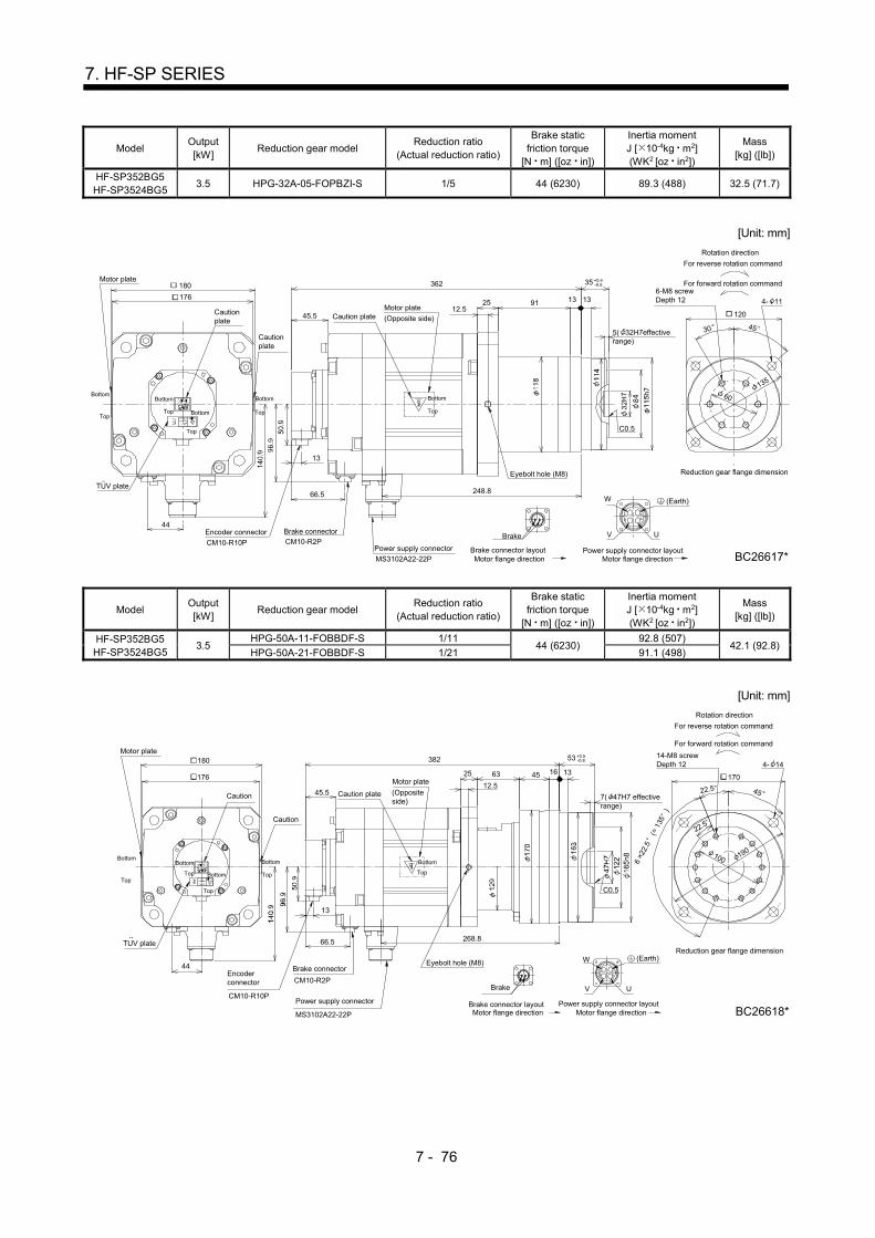
7 - 76
7. HF-SP SERIES
Model Output [kW]
Reduction gear model Reduction ratio
(Actual reduction ratio)
Brake static friction torque
[N m] ([oz in])
Inertia moment J [ 10-4kg m2] (WK2 [oz in2])
Mass [kg] ([lb])
HF-SP352BG5 HF-SP3524BG5
3.5 HPG-32A-05-FOPBZI-S 1/5 44 (6230) 89.3 (488) 32.5 (71.7)
[Unit: mm]
MS3102A22-22P
Power supply connector
AB
C D
Motor plate
Cautionplate
Cautionplate
TUV plate
176
44
Motor plate
(Opposite side)Caution plate
Encoder connector
CM10-R10P
13
66.5
Brake connectorCM10-R2P
45.5
V
W
UBrake
248.8
362
12.525
C0.5
45
135
4- 11
120
5( 32H7effectiverange)
13 1391
60
6-M8 screwDepth 12
180
30
(Earth)
Motor flange directionMotor flange directionBrake connector layout Power supply connector layout
Top
Bottom
Top
Bottom
Top Bottom
Bottom
Top
Reduction gear flange dimension
BC26617*
Rotation direction
For forward rotation command
For reverse rotation command
+0.4-0.535
Eyebolt hole (M8)
Top
Bottom
Model Output [kW]
Reduction gear model Reduction ratio
(Actual reduction ratio)
Brake static friction torque
[N m] ([oz in])
Inertia moment J [ 10-4kg m2] (WK2 [oz in2])
Mass [kg] ([lb])
HF-SP352BG5 HF-SP3524BG5
3.5 HPG-50A-11-FOBBDF-S 1/11
44 (6230) 92.8 (507)
42.1 (92.8) HPG-50A-21-FOBBDF-S 1/21 91.1 (498)
[Unit: mm]
63
382
268.8
Brake
Caution plate
Motor plate
(Oppositeside)
25
4522.5
B A
UV
D
WC
22.5
170
190100
7( 47H7 effectiverange)
45 1316
C0.5
14-M8 screwDepth 12 4- 14
66.5
13
Encoderconnector
TUV plate
CM10-R10P
44
Power supply connector
CM10-R2P
Brake connector
MS3102A22-22P
180
176
Motor plate
Caution 45.5
Caution
12.5
+0.5-0.853
6 2
2.5
(
135
)
(Earth)
Brake connector layoutMotor flange direction
Reduction gear flange dimension
BC26618*Power supply connector layout
Motor flange direction
For forward rotation command
For reverse rotation command
Rotation direction
Top
Bottom
Top
Bottom
Top
Bottom Top
Bottom
Top
Bottom
Eyebolt hole (M8)

7 - 77
7. HF-SP SERIES
Model Output [kW]
Reduction gear model Reduction ratio
(Actual reduction ratio)
Brake static friction torque
[N m] ([oz in])
Inertia moment J [ 10-4kg m2] (WK2 [oz in2])
Mass [kg] ([lb])
HF-SP502BG5 HF-SP5024BG5
5.0 HPG-50A-05-FOBBCF-S 1/5
44 (6230) 117.1 (640) 44.6 (98.3)
HPG-50A-11-FOBBDF-S 1/11 115.1 (629) 46.1(102)
[Unit: mm]
Brake connectorCM10-R2P
13
45.5
66.5
288.8
402
63
12.5
25
C0.5
131645
44
82
BC26619C
100
Encoder connector
Power supply connector
AB
V U
MS3102A22-22P
CM10-R10P
WC D
Motor plate
Caution plateCaution plate
Motor plate(Opposite side)
190
170
14-M8 screwDepth 12 4- 14
7( 47H7effective range)
180
176
Caution plate
Eyebolt hole (M8) (Earth)
6 2
2.5
(
135
)
Motor flange directionPower supply connector layout
Top
BottomTop
Bottom
Top
Bottom
Top
Bottom
Reduction gear flange dimension
For forward rotation command
Rotation direction
For reverse rotation command
Top
Bottom
Brake
Motor flange directionBrake connector layout
TUV plate
22.5 45
22.5
+0.5-0.853
Model Output [kW]
Reduction gear model Reduction ratio
(Actual reduction ratio)
Brake static friction torque
[N m] ([oz in])
Inertia moment J [ 10-4kg m2] (WK2 [oz in2])
Mass [kg] ([lb])
HF-SP702BG5 HF-SP7024BG5
7.0 HPG-50A-05-FOBBCF-S 1/5 44 (6230) 174.1 (952) 53.6 (118)
[Unit: mm]
Motor plate
(Opposite side)
Caution plate
CM10-R10PEncoder connector
Brake connector
CM10-R2PMS3102A32-17P
Brake
44
Motorplate
Power supply connector
V
W
U
A
D
CB
13
45.5
Cautionplate
66.5
340.8
462
63
12.5
25
100
190
22.5 45
C0.5
7( 47H7 effectiverange)
131645
170
22.5
14-M8 screwDepth 12 4- 14180
Cautionplate
176
Eyebolt hole (M8)
6 2
2.5
(
135
)
(Earth)
Motor flange directionBrake connector layout
Top
Bottom
Top
Bottom
Power supply connector layoutMotor flange direction
Top
Reduction gear flange dimension
BC26620*
For forward rotation command
For reverse rotation command
Rotation direction
+0.5-0.853
BottomTopBottom
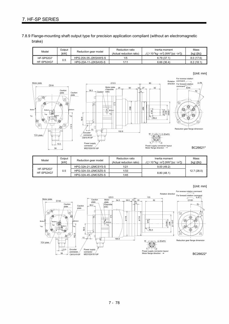
7 - 78
7. HF-SP SERIES
7.8.9 Flange-mounting shaft output type for precision application compliant (without an electromagnetic
brake)
Model Output
[kW] Reduction gear model
Reduction ratio
(Actual reduction ratio)
Inertia moment
J [ 10-4kg m2] (WK2 [oz in2])
Mass
[kg] ([lb])
HF-SP52G7
HF-SP524G7 0.5
HPG-20A-05-J2KSAWS-S 1/5 6.79 (37.1) 8.0 (17.6)
HPG-20A-11-J2KSAXS-S 1/11 6.66 (36.4) 8.2 (18.1)
[Unit: mm]
U
W
V
C
B
D
A
Cautionplate
Motor plate
Caution
Motor plate(Oppositeside)
Encoderconnector
CM10-R10P
13
38.2
130
TUV plate..
Cautionplate
13.5
58
Power supplyconnector
MS3102A18-10P
10
8
602545
105
R0.4
80
4227 90
4- 9
152.8
213.5
BC26621*
(Earth)
TopTop
Top
Bottom Top
Bottom Bottom Bottom
Motor flange directionPower supply connector layout
Reduction gear flange dimension
For forward rotationcommand
For reverse rotationcommandRotation
direction
Bottom
Top
Model Output
[kW] Reduction gear model
Reduction ratio
(Actual reduction ratio)
Inertia moment
J [ 10-4kg m2] (WK2 [oz in2])
Mass
[kg] ([lb])
HF-SP52G7
HF-SP524G7 0.5
HPG-32A-21-J2MCSYS-S 1/21 9.00 (49.2)
12.7 (28.0) HPG-32A-33-J2MCSZS-S 1/33 8.80 (48.1)
HPG-32A-45-J2MCSZS-S 1/45
[Unit: mm]
164.8
225.5
1339.5
U
58
TUV plate..
13.5 Power supplyconnectorMS3102A18-10P
Encoderconnector
CM10-R10P
13
W
V
BC
AD
130
Cautionplate
Motor plate Cautionplate
Cautionplate
38.2
Motorplate
54.5
(Oppositeside)
45
120
135
82
133
13
35
R0.4
4- 11
(Earth)
Power supply connector layoutMotor flange direction
BottomBottom
TopTop
Bottom
Top
Bottom
Top
Reduction gear flange dimension
For forward rotation command
For reverse rotation commandRotation direction
BC26622*
Bottom
Top

7 - 79
7. HF-SP SERIES
Model Output
[kW] Reduction gear model
Reduction ratio
(Actual reduction ratio)
Inertia moment
J [ 10-4kg m2] (WK2 [oz in2])
Mass
[kg] ([lb])
HF-SP102G7
HF-SP1024G7 1.0 HPG-20A-05-J2KSAWS-S 1/5 12.6 (68.9) 9.7 (21.4)
[Unit: mm]
U
W
V
C
B
D
A
Cautionplate
38.2Cautionplate
Motor plate(Oppositeside)
Cautionplate
Motor plate130
TUV plate
Encoder connectorCM10-R10P
13
MS3102A18-10P
Power supplyconnector
58
13.5
60 1025
R0.4
45
105
80
4227
8 90
4- 9235.5
174.8
(Earth)
TopTop
Top
Bottom Top
Bottom Bottom Bottom
Motor flange directionPower supply connector layout
Reduction gear flange dimension
For forward rotationcommand
For reverse rotationcommandRotation
direction
BC26623*
Bottom
Top
Model Output
[kW] Reduction gear model
Reduction ratio
(Actual reduction ratio)
Inertia moment
J [ 10-4kg m2] (WK2 [oz in2])
Mass
[kg] ([lb])
HF-SP102G7
HF-SP1024G7 1.0
HPG-32A-11-J2MCSPS-S 1/11 15.3 (83.7) 14.4 (31.7)
HPG-32A-21-J2MCSYS-S 1/21 14.8 (80.9)
[Unit: mm]
U
247.5
186.8
39.5
CM10-R10PEncoder connector
58
..TUV plate
13.5
Power supplyMS3102A18-10P
13
V
W
BC D
A
130
Cautionplate
Motor plate
38.2Cautionplate
Cautionplate
54.5Motorplate
(Oppositeside)
R0.4
82
133
13
13
35
45
120
4- 11
(Earth)
Motor flange directionPower supply connector layout
Top
Top
Bottom
Top
Bottom
Bottom Top
Bottom
Reduction gear flange dimension
For reverse rotationcommand
For forward rotationcommandRotation
direction
BC26624*
Top
Bottom

7 - 80
7. HF-SP SERIES
Model Output
[kW] Reduction gear model
Reduction ratio
(Actual reduction ratio)
Inertia moment
J [ 10-4kg m2] (WK2 [oz in2])
Mass
[kg] ([lb])
HF-SP102G7
HF-SP1024G7 1.0
HPG-50A-33-J2AABC-S 1/33 16.6 (90.8) 25.5 (56.2)
HPG-50A-45-J2AABC-S 1/45
[Unit: mm]
263.5
202.8
107
CM10-R10PEncoder connector
5
..TUV plate
13.5
Power supplyconnectorMS3102A18-10P
13
DC
V
B A
W
130
Cautionplate
Motor plate
38.2
Cautionplate
Cautionplate
Motorplate
(Oppositeside)
45
190
R0.4
U
170156
82531613
4- 14
(Earth)
Top
Top
Bottom
Bottom Top
Reduction gear flange dimension
Power supply connector layout
For forward rotationcommand
For reverse rotationcommand
Rotationdirection
Motor flange direction BC26625*
Bottom
Top
Bottom Bottom
Top
Model Output
[kW] Reduction gear model
Reduction ratio
(Actual reduction ratio)
Inertia moment
J [ 10-4kg m2] (WK2 [oz in2])
Mass
[kg] ([lb])
HF-SP152G7
HF-SP1524G7 1.5 HPG-20A-05-J2KSAWS-S 1/5 18.5 (101) 11.5 (25.4)
[Unit: mm]
U
W
V
C
B
D
A
38.2Cautionplate
Cautionplate
58
13.5
..TUV plate
CM10-R10P
Encoderconnector
13
Power supplyconnectorMS3102A18-10P
Motor plate
(Opposite side)
Cautionplate
130Motor plate
6025
R0.4
45
105
10
80
422790
4- 9
196.8
257.5
BC26626*
(Earth)
TopTop
Top
Bottom Top
Bottom Bottom Bottom
Power supply connector layoutMotor flange direction
Reduction gear flange dimension
For forward rotation command
For reverse rotation commandRotationdirection
Bottom
Top

7 - 81
7. HF-SP SERIES
Model Output
[kW] Reduction gear model
Reduction ratio
(Actual reduction ratio)
Inertia moment
J [ 10-4kg m2] (WK2 [oz in2])
Mass
[kg] ([lb])
HF-SP152G7
HF-SP1524G7 1.5 HPG-32A-11-J2MCSPS-S 1/11 21.2 (116) 16.2 (35.7)
[Unit: mm]
208.8
269.5
39.5
EncoderconnectorCM10-R10P
58
..TUV plate
13.5 Power supplyconnector
MS3102A18-10P
13
V U
W
B
CAD
130
Cautionplate
Motor plate
38.2Cautionplate
Cautionplate
54.5Motorplate
(Oppositeside)
R0.4
45
135
12082
133
13
13
35
4- 11
(Earth)
Top
Motor flange directionPower supply connector layout
Top
Bottom
Top
Bottom
Bottom Top
Bottom
Reduction gear flange dimension
Rotationdirection For reverse rotation
command
For forward rotationcommand
BC26627*
Bottom
Top
Model Output
[kW] Reduction gear model
Reduction ratio
(Actual reduction ratio)
Inertia moment
J [ 10-4kg m2] (WK2 [oz in2])
Mass
[kg] ([lb])
HF-SP152G7
HF-SP1524G7 1.5
HPG-50A-21-J2AABC-S 1/21 23.5 (128)
27.3 (60.2) HPG-50A-33-J2AABC-S 1/33 22.5 (123)
HPG-50A-45-J2AABC-S 1/45
[Unit: mm]
224.8
285.5
107
Encoder connectorCM10-R10P58
..TUV plate
13.5
Power supplyconnector
MS3102A18-10P
13
DC
UV
B A
W
130
Cautionplate
Motor plate
38.2
Cautionplate
Cautionplate Motor
(Oppositeside)
R0.4
190
45
15
8253
13
16170
4- 14
Earth
Top
Motor flange directionPower supply connector layout
Top
Bottom
Bottom Top
Reduction gear flange dimension
For forward rotationcommand
Rotationdirection
For reverse rotationcommand
BC26628*
Bottom
Top
Bottom
Top
Bottom

7 - 82
7. HF-SP SERIES
Model Output
[kW] Reduction gear model
Reduction ratio
(Actual reduction ratio)
Inertia moment
J [ 10-4kg m2] (WK2 [oz in2])
Mass
[kg] ([lb])
HF-SP202G7
HF-SP2024G7 2.0
HPG-32A-05-J2PBZI-S 1/5 43.2 (236) 20.9 (46.1)
HPG-32A-11-J2PBZJ-S 1/11 42.8 (234) 21.4 (47.2)
[Unit: mm]
Cautionplate
W
13
TUV plate
Caution plate
..
Motor plate(Oppositeside)
UV
C
B
D
A
Motor plate
176
CM10-R10P
Encoderconnector
MS3102A22-22P
Power supplyconnector82
38.5
9125
13
82
133
3513
R0.4
208.8
Screw depth (M8)
272.5
12.5
45
120
135
4- 11180
Cautionplate
(Earth)
Top
Top
Bottom
Bottom
Bottom
Top
Power supplyMotor flange direction
Reduction gear flange dimension
For reverse rotationcommand
For forward rotationcommand
Rotationdirection
Top
Bottom
BC26629*
Bottom
Top
Model Output
[kW] Reduction gear model
Reduction ratio
(Actual reduction ratio)
Inertia moment
J [ 10-4kg m2] (WK2 [oz in2])
Mass
[kg] ([lb])
HF-SP202G7
HF-SP2024G7 2.0
HPG-50A-21-J2BBDF-S 1/21 44.8 (245)
32.1 (70.8) HPG-50A-33-J2BBDF-S 1/33 43.7 (239)
HPG-50A-45-J2BBDF-S 1/45
[Unit: mm]
82
176
180
Motor plate
Caution plate
TUV plate..
292.5
228.8
63
13
Power supply connector
MS3102A22-22P
EncoderconnectorCM10-R10P
V
CB
DA
U
W
Cautionplate
38.5
12.5(Oppositeside)
Motor plate25
R0.4
82
156
53
13
1645
45
190
1704- 14
Cautionplate
Screw depth (M8) (Earth)
Top
Bottom Bottom
Top
Top
Bottom
Power supply connector layoutMotor flange direction
Reduction gear flange dimension
Rotationdirection
For reverse rotationcommand
For forward rotationcommand
Bottom
Top
BC26630*
Top
Bottom
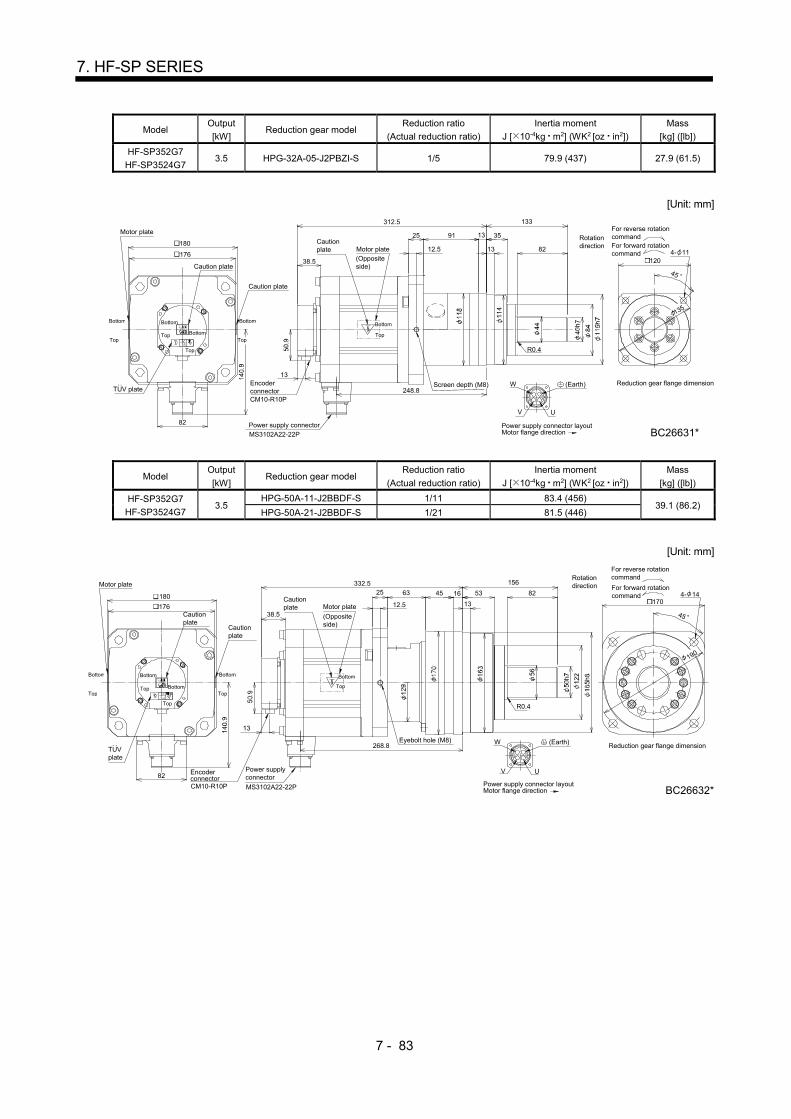
7 - 83
7. HF-SP SERIES
Model Output
[kW] Reduction gear model
Reduction ratio
(Actual reduction ratio)
Inertia moment
J [ 10-4kg m2] (WK2 [oz in2])
Mass
[kg] ([lb])
HF-SP352G7
HF-SP3524G7 3.5 HPG-32A-05-J2PBZI-S 1/5 79.9 (437) 27.9 (61.5)
[Unit: mm]
248.8
312.5
91
TUV plate
13
82
MS3102A22-22P
CM10-R10P
Encoderconnector
Power supply connector
V U
CB A
D
W
176
Motor plate
Caution plate
Cautionplate
Caution plate
38.5
12.5Motor plate(Oppositeside)
25
45
135
120
133
82
13 35
13
R0.4
4- 11180
Reduction gear flange dimension
Motor flange directionPower supply connector layout
Top
Bottom Bottom
Top
Top
Bottom
Bottom
For forward rotationcommand
Rotationdirection
For reverse rotationcommand
..
BC26631*
Top
Screen depth (M8)
Bottom
Top
(Earth)
Model Output
[kW] Reduction gear model
Reduction ratio
(Actual reduction ratio)
Inertia moment
J [ 10-4kg m2] (WK2 [oz in2])
Mass
[kg] ([lb])
HF-SP352G7
HF-SP3524G7 3.5
HPG-50A-11-J2BBDF-S 1/11 83.4 (456) 39.1 (86.2)
HPG-50A-21-J2BBDF-S 1/21 81.5 (446)
[Unit: mm]
332.5
268.8
63
13
82
MS3102A22-22PCM10-R10P
Encoderconnector
Power supplyconnector
V U
CB A
D
W
176
Motor plate
Cautionplate
Cautionplate
Cautionplate
38.5
12.5Motor plate
(Oppositeside)
25
156
5316
13
45 82
R0.4
45
190
1704- 14180
(Earth)TUVplate
Motor flange directionPower supply connector layout
Top
Bottom Bottom
Top
Top
Bottom
Bottom
TopTop
Reduction gear flange dimension
For forward rotationcommand
For reverse rotationcommandRotation
direction
Bottom
Eyebolt hole (M8)
BC26632*

7 - 84
7. HF-SP SERIES
Model Output
[kW] Reduction gear model
Reduction ratio
(Actual reduction ratio)
Inertia moment
J [ 10-4kg m2] (WK2 [oz in2])
Mass
[kg] ([lb])
HF-SP502G7
HF-SP5024G7 5.0
HPG-50A-05-J2BBCF-S 1/5 108.5 (593) 41.6 (91.7)
HPG-50A-11-J2BBDF-S 1/11 105.4 (576) 43.1 (95.0)
[Unit: mm]
13
38.5
288.8
25
352.5
1645
12.5
63
R0.
156
8253
13
82
BC26633C
Encoder connectorPower supply connector
AB
V U
MS3102A22-22PCM10-R10P
W
C D
Motor plate Cautionplate
Caution plate
Motor plate(Opposite side)
190
170
4- 14
180
176
Caution plate
Eyebolt hole (M8)
(Earth)
Motor flange directionPower supply connector layout
Top
Bottom
Top
Bottom
Top
Bottom
Top
Bottom
Reduction gear flange dimension
For forward rotation command
Rotation direction
For reverse rotation command
Top
Bottom
TUV plate
45
Model Output
[kW] Reduction gear model
Reduction ratio
(Actual reduction ratio)
Inertia moment
J [ 10-4kg m2] (WK2 [oz in2])
Mass
[kg] ([lb])
HF-SP702G7
HF-SP7024G7 7.0 HPG-50A-05-J2BBCF-S 1/5 165.5 (905) 50.6 (112)
[Unit: mm]
13
Encoder connector
CM10-R10P
Caution plateMotor plate
Caution plateCaution plate
38.5 Motor plate
(Oppositeside)
340.8
412.5
12.5
UV
W
CB
DA
180
MS3102A32-17P
Power supply connector
6325
45
16 82
13
45 53
156
R0.4
170
190
4- 14
176
82
BC26634*
(Earth)
Top
Bottom
Top
Bottom
Top
Bottom
Motor flange directionPower supply
Reduction gear flange dimension
For forward rotationcommand
For reverse rotationcommandRotation
direction
Eyebolt hole (M8)
Bottom
Top

7 - 85
7. HF-SP SERIES
7.8.10 Flange-mounting shaft output type for precision application compliant (with an electromagnetic brake)
Model Output [kW]
Reduction gear model Reduction ratio
(Actual reduction ratio)
Brake static friction torque
[N m] ([oz in])
Inertia moment J [ 10-4kg m2] (WK2 [oz in2])
Mass [kg] ([lb])
HF-SP52BG7
HF-SP524BG7 0.5
HPG-20A-05-J2KSAWS-S 1/5 8.5 (1200)
8.99 (49.2) 9.9 (21.8)
HPG-20A-11-J2KSAXS-S 1/11 8.86 (48.4) 10.1 (22.3)
[Unit: mm]
130
TUV plate
58
13.5
Caution plate
Motor plate
DA
C
W
B
UV
Cautionplate (Opposite
side)
Motor plate
Caution plate
29
43.5
13
Encoder connector
59
Brake connectorCM10-R2P
CM10-R10P Power supply connectorMS3102A18-10P
Brake
45 90
4- 960 1025
80
4227
8
R0.4
152.8
248
BC26635*
Bottom
Top
Motor flange direction
Top
Power supply connector layout
Top
Bottom
Top
BottomTop
Bottom
Brake connector layoutMotor flange direction
Reduction gearflange dimension
For forward rotation command
For reverse rotation commandRotation direction
(Earth)
Bottom
Model Output [kW]
Reduction gear model Reduction ratio
(Actual reduction ratio)
Brake static friction torque
[N m] ([oz in])
Inertia moment J [ 10-4kg m2] (WK2 [oz in2])
Mass [kg] ([lb])
HF-SP52BG7
HF-SP524BG7 0.5
HPG-32A-21-J2MCSYS-S 1/21
8.5 (1200)
11.2 (61.2)
14.6 (32.2) HPG-32A-33-J2MCSZS-S 1/33 11.0 (60.1)
HPG-32A-45-J2MCSZS-S 1/45
[Unit: mm]
54.5 35
133
39.5 13
R0.4
82
120
45
135
164.8
130
TUV plate
58
13.5
Cautionplate
260
Motor plate
DA
C
W
B
UV
Cautionplate (Opposite
side)
Motorplate
Cautionplate
4- 11
43.5
13
Encoder connector
59
Brake connectorCM10-R2P
CM10-R10P Power supply connectorMS3102A18-10P
Brake
13
29
(Earth)Reduction gear flangedimension
Rotation directionFor reverse rotation command
For forward rotation command
Bottom
Top
Motor flange direction
Top
Power supply connector layout
Top
Bottom
Top
BottomTop
Bottom
Brake connector layoutMotor flange direction BC26496*
Bottom

7 - 86
7. HF-SP SERIES
Model Output [kW]
Reduction gear model Reduction ratio
(Actual reduction ratio)
Brake static friction torque
[N m] ([oz in])
Inertia moment J [ 10-4kg m2] (WK2 [oz in2])
Mass [kg] ([lb])
HF-SP102BG7 HF-SP1024BG7
1.0 HPG-20A-05-J2KSAWS-S 1/5 8.5 (1200) 14.7 (80.4) 11.7 (25.8)
[Unit: mm]
59
W
V
D
U
B A
C
43.5Cautionplate
Motor plate
Cautionplate
TUV plate
130
Power supply connectorMS3102A18-10P
13
CM10-R2PBrake connector
Caution plate
Motor plate(Opposite side)
Brake29 13.5
CM10-R10P
Encoderconnector
6025
R0.4
105
45
8
10 27 42
80
904- 9
270
174.8
58
(Earth)
Top
Top
Bottom
Top
Bottom
TopBottom
Bottom
Top
Motor flange directionBrake connector layout Power supply connector layout
Motor flange direction
Reduction gearflange dimension
For forward rotation command
For reverse rotation commandRotation direction
BC26637*
Bottom
Model Output [kW]
Reduction gear model Reduction ratio
(Actual reduction ratio)
Brake static friction torque
[N m] ([oz in])
Inertia moment J [ 10-4kg m2] (WK2 [oz in2])
Mass [kg] ([lb])
HF-SP102BG7 HF-SP1024BG7
1.0 HPG-32A-11-J2MCSPS-S 1/11
8.5 (1200) 17.4 (95.1)
16.4 (36.2) HPG-32A-21-J2MCSYS-S 1/21 16.9 (92.4)
[Unit: mm]
282
186.8
54.5
Encoder connector
13
TUV plate59
CM10-R10P
29 13.5
MS3102A18-10PPower supply connector
Brake connectorCM10-R2P
Cautionplate
Motor plate
Cautionplate
130
Cautionplate
43.5
Motor plate(Oppositeside)
V
W
Brake U
ACB
D
82
133
R0.4
35
13
39.5 13
45
120
135
58
BC26638*
(Earth)
Brake connector layout
Top
Bottom
Top
Bottom
Top
Bottom Top
Bottom
Top
Motor flange directionPower supply connector layout
Motor flange direction
Rotation direction
Reduction gearflange dimension
For forward rotation command
For reverse rotation command
4- 11
Bottom

7 - 87
7. HF-SP SERIES
Model Output [kW]
Reduction gear model Reduction ratio
(Actual reduction ratio)
Brake static friction torque
[N m] ([oz in])
Inertia moment J [ 10-4kg m2] (WK2 [oz in2])
Mass [kg] ([lb])
HF-SP102BG7 HF-SP1024BG7
1.0 HPG-50A-33-J2AABC-S 1/33
8.5 (1200) 18.7 (102) 27.5 (60.6) HPG-50A-45-J2AABC-S 1/45
[Unit: mm]
W
V
107298
CB
202.8
16
TUV plate
Encoder connector
CM10-R10P
13.52
Power supply connectorMS3102A18-10P
Brake connectorCM10-R2P
5913
Brake
Cautionplate
Motor plate
130
Cautionplate
Motor plate
Caution plate
(Opposite side)
43.5
R0.4
U
AD
82156
53
13
190
45
1704- 14
58
BC26639*
(Earth)
Motor flange directionPower supply connector layout
Top
Brake connector layoutMotor flange direction
Top BottomTop
Bottom
Top
Reduction gearflange dimension
For reverse rotation command
For forward rotation commandRotation direction
Bottom Bottom Bottom
Top
Model Output [kW]
Reduction gear model Reduction ratio
(Actual reduction ratio)
Brake static friction torque
[N m] ([oz in])
Inertia moment J [ 10-4kg m2] (WK2 [oz in2])
Mass [kg] ([lb])
HF-SP152BG7 HF-SP1524BG7
1.5 HPG-20A-05-J2KSAWS-S 1/5 8.5 (1200) 20.7 (113) 13.5 (29.8)
[Unit: mm]
196.8
292
60
W
V
59
13
TUV plate
CM10-R10P
Encoder connector29 13.5
MS3102A18-10PPower supply connector
CM10-R2PBrake connector
Brake
Cautionplate
Motor plate 130
Cautionplate Caution
plate43.5
Motor plate(Oppositeside)
25
45
DC
U
B A
105
9042
80
8
2710
R0.4
4- 9
58
(Earth)
Motor flange directionPower supply connector layout
Motor flange directionBrake connector layout
Bottom
TopTop
Bottom
Top
Bottom Top
Bottom
Top
Reduction gearflange dimension
Rotation directionFor reverse rotation command
For forward rotation command
BC26640*
Bottom
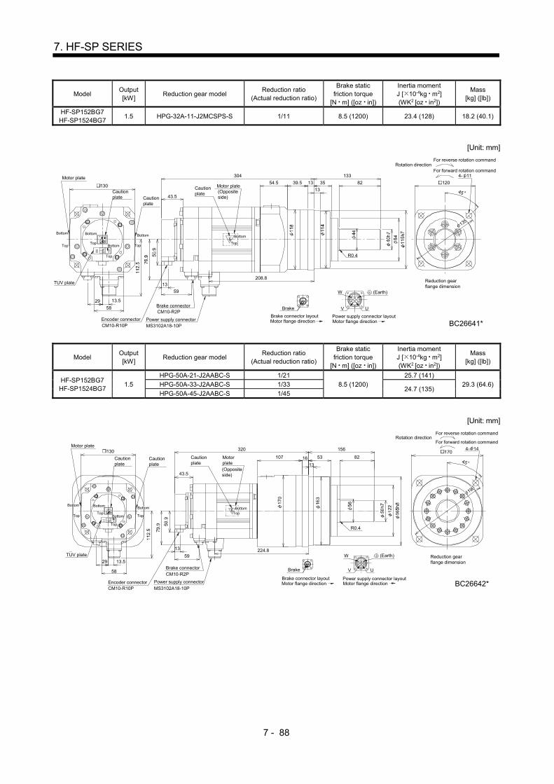
7 - 88
7. HF-SP SERIES
Model Output [kW]
Reduction gear model Reduction ratio
(Actual reduction ratio)
Brake static friction torque
[N m] ([oz in])
Inertia moment J [ 10-4kg m2] (WK2 [oz in2])
Mass [kg] ([lb])
HF-SP152BG7 HF-SP1524BG7
1.5 HPG-32A-11-J2MCSPS-S 1/11 8.5 (1200) 23.4 (128) 18.2 (40.1)
[Unit: mm]
208.8
304
54.5
W
V
59
13TUV plate
CM10-R10PEncoder connector
29 13.5
MS3102A18-10PPower supply connector
CM10-R2PBrake connector Brake
Cautionplate
Motor plate
130Cautionplate
Cautionplate
43.5
Motor plate(Oppositeside)
45
DC
U
B A
133
82351339.5
13
R0.4
120
135
4- 11
58
(Earth)
Motor flange directionPower supply connector layout
Motor flange directionBrake connector layout
Bottom
TopTop
Bottom
Top
Bottom Top
Bottom
Top
Reduction gearflange dimension
For reverse rotation command
For forward rotation commandRotation direction
BC26641*
Bottom
Model Output [kW]
Reduction gear model Reduction ratio
(Actual reduction ratio)
Brake static friction torque
[N m] ([oz in])
Inertia moment J [ 10-4kg m2] (WK2 [oz in2])
Mass [kg] ([lb])
HF-SP152BG7 HF-SP1524BG7
1.5
HPG-50A-21-J2AABC-S 1/21
8.5 (1200)
25.7 (141)
29.3 (64.6) HPG-50A-33-J2AABC-S 1/33 24.7 (135)
HPG-50A-45-J2AABC-S 1/45
[Unit: mm]
320
224.8
107
W
V
59
13TUV plate
CM10-R10PEncoder connector
29 13.5
MS3102A18-10PPower supply connector
CM10-R2PBrake connector Brake
Cautionplate
Motor plate 130
Cautionplate
Cautionplate
43.5
Motorplate(Oppositeside)
190
45
DC
U
B A
53
156
13
16 82
R0.4
4- 14 170
58
(Earth)
Motor flange directionPower supply connector layout
Motor flange directionBrake connector layout
TopTop
Bottom
Top
Bottom Top
Reduction gearflange dimension
For forward rotation command
For reverse rotation commandRotation direction
BC26642*
BottomBottom Bottom
Top
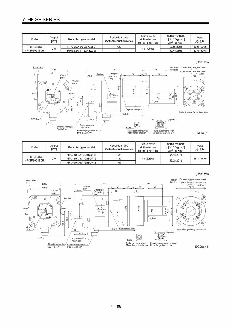
7 - 89
7. HF-SP SERIES
Model Output [kW]
Reduction gear model Reduction ratio
(Actual reduction ratio)
Brake static friction torque
[N m] ([oz in])
Inertia moment J [ 10-4kg m2] (WK2 [oz in2])
Mass [kg] ([lb])
HF-SP202BG7 HF-SP2024BG7
2.0 HPG-32A-05-J2PBZI-S 1/5
44 (6230) 52.8 (289) 26.9 (59.3)
HPG-32A-11-J2PBZJ-S 1/11 52.4 (286) 27.4 (60.4)
[Unit: mm]
208.8
322
91
66.5
13
Encoder connector
TUV plate
44
MS3102A22-22PPower supply connector
CM10-R2PBrake connector
CM10-R10PBrake
176
Motor plate
Cautionplate
Caution45.5
Cautionplate
Motor plate(Oppositeside)
25
45
B A
UV
W
C D
120
135
133
82
13
13 35
R0.4
4- 11
180
12.5
Eyebolt hole (M8)
(Earth)
Brake connector layoutMotor flange direction
Top
Bottom
Top
Bottom
Top
BottomTop
Bottom
Reduction gear flange dimension
Power supply connectorMotor flange direction
For reverse rotation command
For forward rotation command
Rotationdirection
Bottom
Top
BC26643*
Model Output [kW]
Reduction gear model Reduction ratio
(Actual reduction ratio)
Brake static friction torque
[N m] ([oz in])
Inertia moment J [ 10-4kg m2] (WK2 [oz in2])
Mass [kg] ([lb])
HF-SP202BG7 HF-SP2024BG7
2.0
HPG-50A-21-J2BBDF-S 1/21
44 (6230)
54.4 (297)
38.1 (84.0) HPG-50A-33-J2BBDF-S 1/33 53.3 (291)
HPG-50A-45-J2BBDF-S 1/45
[Unit: mm]
228.8
342
63
66.5
13
Encoder connector
TUVplate
44
MS3102A22-22P
Power supply connector
Eyebolt hole (M8)
CM10-R2P
Brake connector
CM10-R10P
Brake
180
176
Motor plate
Cautionplate
Cautionplate
45.5
Caution
12.5Motor plate(Oppositeside)
25
45
B A
UV
W
C D
170
156
5316
13
45 82
R0.4
4- 14
..
190
(Earth)
Brake connector layoutMotor flange direction
Top
Bottom
Top
Bottom
BottomTop
Bottom
Power supply connector layoutMotor flange direction
Reduction gear flange dimension
For reverse rotation command
For forward rotation command
Rotationdirection
Top
BC26644*
Bottom
Top

7 - 90
7. HF-SP SERIES
Model Output [kW]
Reduction gear model Reduction ratio
(Actual reduction ratio)
Brake static friction torque
[N m] ([oz in])
Inertia moment J [ 10-4kg m2] (WK2 [oz in2])
Mass [kg] ([lb])
HF-SP352BG7 HF-SP3524BG7
3.5 HPG-32A-05-J2PBZI-S 1/5 44 (6230) 89.6 (490) 33.9 (74.7)
[Unit: mm]
248.8
362
91
12.5
25
45
120
133
82
R0.4
13
13 35 4- 11
TUV plate
13
66.5
Encoder connector44
CM10-R10PBrake
Power supplyMS3102A22-22P
Brake connectorCM10-R2P
Cautionplate
Motor plate
176
180
Cautionplate
(Oppositeside)
Motor plateCautionplate
Eyebolt hole (M8)
45.5
UV
W
ABC D
..
BC26645*
(Earth)
Reduction gear flangedimension
For forward rotation command
For reverse rotation commandRotationdirection
Top
Bottom
Top
Top
Bottom
BottomTop
Bottom
Motor flange directionBrake connector layout
Motor flange directionPower supply connector layout
Bottom
Top
135
Model Output [kW]
Reduction gear model Reduction ratio
(Actual reduction ratio)
Brake static friction torque
[N m] ([oz in])
Inertia moment J [ 10-4kg m2] (WK2 [oz in2])
Mass [kg] ([lb])
HF-SP352BG7 HF-SP3524BG7
3.5 HPG-50A-11-J2BBDF-S 1/11
44 (6230) 93.1 (509)
45.1 (99.4) HPG-50A-21-J2BBDF-S 1/21 91.2 (499)
[Unit: mm]
268.8
382
63
66.5
13
Encoder connector
TUV plate
CM10-R10P
..
44
Power supply
CM10-R2P
Brake connector
MS3102A22-22P
Brake
180176
Motor plate
Cautionplate
Cautionplate45.5
Cautionplate
12.5Motor plate(Oppositeside)
25
B A
UV
D
W
C
156
5345 16
13
82
R0.4
45
4- 14170
190
Eyebolt hole (M8)
(Earth)
Brake connector layoutMotor flange direction
Top
Bottom
Top
Bottom
Top
BottomTop
Bottom
Top
Power supply connector layoutMotor flange direction
Reduction gear flange dimension
For forward rotation command
For reverse rotation commandRotationdirection
Bottom
BC26646*
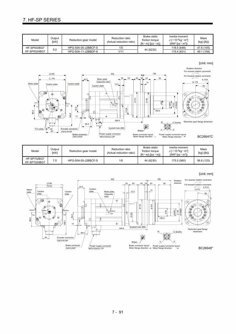
7 - 91
7. HF-SP SERIES
Model Output [kW]
Reduction gear model Reduction ratio
(Actual reduction ratio)
Brake static friction torque
[N m] ([oz in])
Inertia moment J [ 10-4kg m2] (WK2 [oz in2])
Mass [kg] ([lb])
HF-SP502BG7 HF-SP5024BG7
5.0 HPG-50A-05-J2BBCF-S 1/5
44 (6230) 118.5 (648) 47.6 (105)
HPG-50A-11-J2BBDF-S 1/11 115.4 (631) 49.1 (108)
[Unit: mm]
402
288.8
66.5
13
45.525 1645
12.5
63
R0.4
82
156
53
13
44
82
BC26647C
Encoder connector
Power supply connector
AB
V U
MS3102A22-22P
CM10-R10P
W
C D
Motor plate Caution plateCaution plate
Motor plate(Opposite side)
190
1704- 14
180
176
Caution plate
Eyebolt hole (M8)
(Earth)
Motor flange directionPower supply connector layout
Top
BottomTop
Bottom
Top
Bottom
Top
Bottom
Reduction gear flange dimension
For forward rotation command
Rotation direction
For reverse rotation command
Top
Bottom
Brake
Motor flange directionBrake connector layoutBrake connector
CM10-R2P
TUV plate
45
Model Output [kW]
Reduction gear model Reduction ratio
(Actual reduction ratio)
Brake static friction torque
[N m] ([oz in])
Inertia moment J [ 10-4kg m2] (WK2 [oz in2])
Mass [kg] ([lb])
HF-SP702BG7 HF-SP7024BG7
7.0 HPG-50A-05-J2BBCF-S 1/5 44 (6230) 175.5 (960) 56.6 (125)
[Unit: mm]
462
340.8
Brake
66.5
13
Brake connector
CM10-R2P MS3102A32-17P
Encoder connector44
CM10-R10P
Power supply connector
Cautionplate
Motorplate
180
Cautionplate
Cautionplate
(Oppositeside)
Motor plate
45.5
25
V
W
BC
AD
U
1645
12.5
63
190
45
R0.4
Eyebolt hole (M8)
82
156
53
13 1704- 14176
BC26648*
(Earth)
Brake connector layoutMotor flange direction
Top
Bottom
TopTop
Bottom
Motor flange directionPower supply connector layout
Reduction gear flangedimension
Rotationdirection
For reverse rotation command
For forward rotation command
Bottom Bottom
Top

7 - 92
7. HF-SP SERIES
MEMO

8 - 1
8. HA-LP SERIES
8. HA-LP SERIES
This chapter provides information on the servo motor specifications and characteristics. When using the HA-LP
series servo motor, always read the Safety Instructions in the beginning of this manual and chapters 1 to 4, in
addition to this chapter. 8.1 Model name make up
The following describes what each block of a model name indicates. Note that not all the combinations of the symbols exist.
Without
Electromagnetic brake
Symbol Electromagnetic brake
(Note) B With
None
Appearance
Series name
Rated speed
Symbol Speed
1 1000 r/min
1M 1500 r/min
2 2000 r/min
Note. Refer to Table 8.3 for the servo motor compatible with the electromagnetic brake.
Rated output
Symbol Rated output [kW]1000[r/min]
1500[r/min]
2000[r/min]
80 8.0
11K 11.0
12K 12.0
15K 15.0
20K
25.0
22K
20.0
25K
22.0
50 5.0
60 6.0
70 7.0
30K
37K
45K
50K
55K
30.0
37.0
45.0
50.0
55.0
None
Power supply voltage of servo amplifier
Symbol Voltage
Three-phase 200 to 230VAC
4 Three-phase 380 to 480VAC
Note. Without key
Shaft type
Symbol Shaft shape
NoneStandard
(Straight shaft)
K (Note) With keyway

8 - 2
8. HA-LP SERIES
8.2 Standard specifications
8.2.1 Standard specifications list
Servo motor
Item
HA-LP 1000r/min series (200VAC-compatible, low inertia middle large capacity)
601 801 12K1 15K1 20K1 25K1 30K1
(Note 9) 37K1
(Note 9)
Applicable servo amplifier/drive unit
MR-J3- A/B/B-RJ006/T
700 11K 15K 22K DU30K DU37K
Applicable converter unit MR-J3-CR-55K
Continuous running duty (Note 1)
Rated output [kW] 6.0 8.0 12.0 15.0 20.0 25.0 30.0 37.0
Rated torque [N m] 57.3 76.4 115 143 191 239 286 353 [oz in] 8110 10800 16300 20300 27000 33800 40500 50000
Rated speed (Note 1) [r/min] 1000 Maximum speed [r/min] 1200 Instantaneous permissible speed [r/min] 1380
Maximum torque [N m] 172 229 344 415 477 597 716 883 [oz in] 24400 32400 48700 58800 67500 84500 101000 125000
Power rate at continuous rated torque
[kW/s] 313 265 445 373 561 528 626 668
Inertia moment (Note 3)
J [ 10-4kg m2] 105 220 295 550 650 1080 1310 1870
WK2 [oz in2] 574 1200 1610 3010 3550 5900 7160 10200 Recommended ratio of load inertia moment to servo motor shaft inertia moment (Note 2)
10 times or less
Power supply capacity Refer to "Power supply equipment capacity and generated loss of servo
amplifiers" in Servo Amplifier Instruction Manual. Rated current [A] 34 42 61 83 118 118 154 188 Maximum current [A] 102 126 183 249 295 295 385 470
Speed/position detector Encoder common to absolute position and incremental detection systems
(Resolution per servo motor 1 rotation: 262144 pulse/rev)
Cooling fan
Power supply
Voltage frequency
One-phase 200 to 220 VAC/50Hz, One-phase 200 to 230 VAC/60Hz
Three-phase 200 to 230VAC 50Hz/60Hz
Power consumption
[W] 42(50Hz)/ 54(60Hz)
62(50Hz)/ 76(60Hz)
65(50Hz)/ 85(60Hz)
120(50Hz)/ 175(60Hz)
Rated current [A] 0.21(50Hz)/0.25(60Hz)
0.18(50Hz)/ 0.17(60Hz)
0.20(50Hz)/ 0.22(60Hz)
0.65(50Hz)/ 0.80(60Hz)
Thermal sensor
Maximum rating 125VAC/DC, 3A or 250VAC/DC, 2A Minimum rating 6VAC/DC, 0.15A
Accessory Oil seal Insulation class 155(F) Structure Totally-enclosed, force-cooled (IP rating: IP44 (Note 4))
Environmental conditions (Note 5)
Ambient temperature
Operation [ ] 0 to 40 (non-freezing) [ ] 32 to 104 (non-freezing)
Storage [ ] 15 to 70 (non-freezing) [ ] 5 to 158 (non-freezing)
Ambient humidity
Operation 10 to 80%RH (non-condensing) Storage 10 to 90%RH (non-condensing)
Ambience Indoors (no direct sunlight)
Free from corrosive gas, flammable gas, oil mist, dust and dirt. Altitude Max.1000m above sea level Vibration resistance (Note 6)
[m/s2] X, : 11.7, Y : 29.4 X, Y: 9.8
Vibration rank (Note 7) V10
Permissible load for the shaft (Note 8)
L [mm] 85 110 140 170
Radial [N] 2450 2940 3234 4900 6370 [lb] 551 661 727 1100 1430
Thrust [N] 980 1470 1960 [lb] 220 330 441
Mass (Note 3) [kg] 55 95 115 160 180 230 250 335 [lb] 121 209 254 353 397 507 551 739
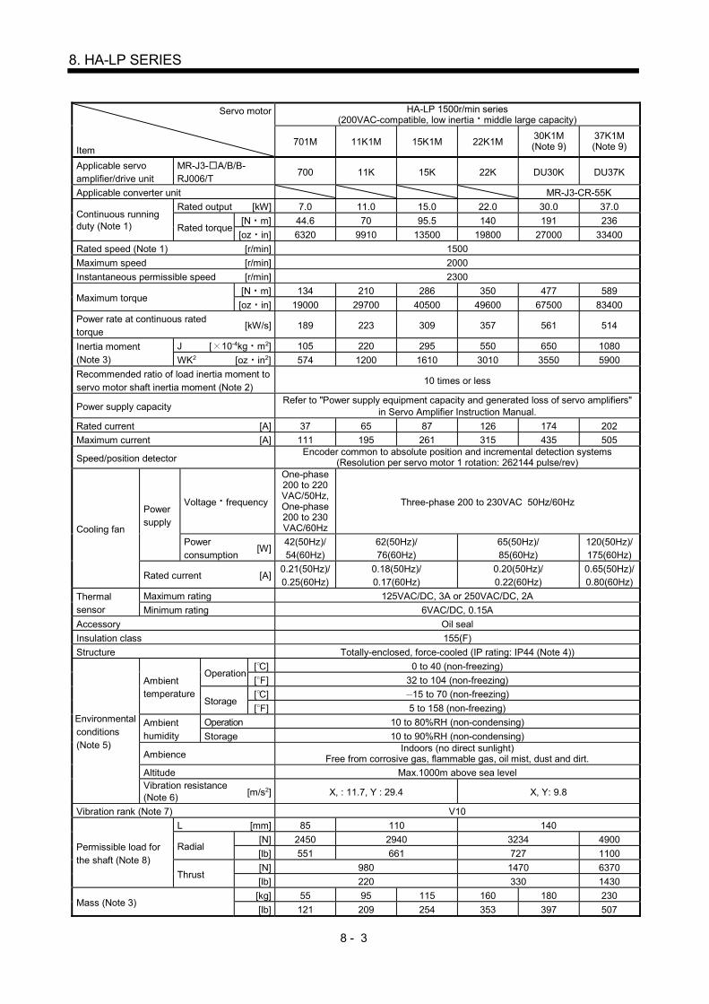
8 - 3
8. HA-LP SERIES
Servo motor
Item
HA-LP 1500r/min series (200VAC-compatible, low inertia middle large capacity)
701M 11K1M 15K1M 22K1M 30K1M (Note 9)
37K1M (Note 9)
Applicable servo amplifier/drive unit
MR-J3- A/B/B-RJ006/T
700 11K 15K 22K DU30K DU37K
Applicable converter unit MR-J3-CR-55K
Continuous running duty (Note 1)
Rated output [kW] 7.0 11.0 15.0 22.0 30.0 37.0
Rated torque [N m] 44.6 70 95.5 140 191 236
[oz in] 6320 9910 13500 19800 27000 33400
Rated speed (Note 1) [r/min] 1500
Maximum speed [r/min] 2000
Instantaneous permissible speed [r/min] 2300
Maximum torque [N m] 134 210 286 350 477 589
[oz in] 19000 29700 40500 49600 67500 83400
Power rate at continuous rated torque
[kW/s] 189 223 309 357 561 514
Inertia moment (Note 3)
J [ 10-4kg m2] 105 220 295 550 650 1080
WK2 [oz in2] 574 1200 1610 3010 3550 5900
Recommended ratio of load inertia moment to servo motor shaft inertia moment (Note 2)
10 times or less
Power supply capacity Refer to "Power supply equipment capacity and generated loss of servo amplifiers"
in Servo Amplifier Instruction Manual.
Rated current [A] 37 65 87 126 174 202
Maximum current [A] 111 195 261 315 435 505
Speed/position detector Encoder common to absolute position and incremental detection systems
(Resolution per servo motor 1 rotation: 262144 pulse/rev)
Cooling fan
Power supply
Voltage frequency
One-phase 200 to 220 VAC/50Hz, One-phase 200 to 230 VAC/60Hz
Three-phase 200 to 230VAC 50Hz/60Hz
Power consumption
[W] 42(50Hz)/ 54(60Hz)
62(50Hz)/ 76(60Hz)
65(50Hz)/ 85(60Hz)
120(50Hz)/ 175(60Hz)
Rated current [A] 0.21(50Hz)/ 0.25(60Hz)
0.18(50Hz)/ 0.17(60Hz)
0.20(50Hz)/ 0.22(60Hz)
0.65(50Hz)/ 0.80(60Hz)
Thermal sensor
Maximum rating 125VAC/DC, 3A or 250VAC/DC, 2A
Minimum rating 6VAC/DC, 0.15A
Accessory Oil seal
Insulation class 155(F)
Structure Totally-enclosed, force-cooled (IP rating: IP44 (Note 4))
Environmental conditions (Note 5)
Ambient temperature
Operation [ ] 0 to 40 (non-freezing)
[ ] 32 to 104 (non-freezing)
Storage [ ] 15 to 70 (non-freezing)
[ ] 5 to 158 (non-freezing)
Ambient humidity
Operation 10 to 80%RH (non-condensing)
Storage 10 to 90%RH (non-condensing)
Ambience Indoors (no direct sunlight)
Free from corrosive gas, flammable gas, oil mist, dust and dirt.
Altitude Max.1000m above sea level Vibration resistance (Note 6) [m/s2] X, : 11.7, Y : 29.4 X, Y: 9.8
Vibration rank (Note 7) V10
Permissible load for the shaft (Note 8)
L [mm] 85 110 140
Radial [N] 2450 2940 3234 4900
[lb] 551 661 727 1100
Thrust [N] 980 1470 6370
[lb] 220 330 1430
Mass (Note 3) [kg] 55 95 115 160 180 230
[lb] 121 209 254 353 397 507

8 - 4
8. HA-LP SERIES
Servo motor
Item
HA-LP 2000r/min series (200VAC-compatible, low inertia middle large capacity)
502 702 11K2 15K2 22K2 30K2
(Note 9) 37K2
(Note 9)
Applicable servo amplifier/drive unit
MR-J3- A/B/B-RJ006/T 500 700 11K 15K 22K DU30K DU37K
Applicable converter unit MR-J3-CR-55K
Continuous running duty (Note 1)
Rated output [kW] 5.0 7.0 11.0 15.0 22.0 30.0 37.0
Rated torque [N m] 23.9 33.4 52.5 71.6 105 143 177
[oz in] 3380 4730 7430 10100 14900 20300 25100
Rated speed (Note 1) [r/min] 2000
Maximum speed [r/min] 2000
Instantaneous permissible speed [r/min] 2300
Maximum torque [N m] 71.6 100 158 215 263 358 442
[oz in] 10100 14200 22400 30400 37200 50700 62600
Power rate at continuous rated torque
[kW/s] 77.2 118 263 233 374 373 480
Inertia moment (Note 3)
J [ 10-4kg m2] 74 94.2 105 220 295 550 650
WK2 [oz in2] 405 515 574 1200 1610 3010 3550 Recommended ratio of load inertia moment to servo motor shaft inertia moment (Note 2) 10 times or less
Power supply capacity Refer to "Power supply equipment capacity and generated loss of servo
amplifiers" in Servo Amplifier Instruction Manual.
Rated current [A] 25 34 63 77 112 166 204
Maximum current [A] 75 102 189 231 280 415 510
Speed/position detector Encoder common to absolute position and incremental detection systems
(Resolution per servo motor 1 rotation: 262144 pulse/rev)
Cooling fan
Power supply
Voltage frequency
One-phase 200 to 220 VAC/50Hz, One-phase 200 to 230 VAC/60Hz
Three-phase 200 to 230VAC 50Hz/60Hz
Power consumption [W]
42(50Hz)/ 54(60Hz)
62(50Hz)/ 76(60Hz)
65(50Hz)/ 85(60Hz)
Rated current [A] 0.21(50Hz)/ 0.25(60Hz)
0.18(50Hz)/ 0.17(60Hz)
0.20(50Hz)/ 0.22(60Hz)
Thermal sensor
Maximum rating 125VAC/DC, 3A or 250VAC/DC, 2A
Minimum rating 6VAC/DC, 0.15A
Accessory Oil seal
Insulation class 155(F)
Structure Totally enclosed,
natural cooling (IP rating: IP65 (Note 4))
Totally-enclosed, force-cooled (IP rating: IP44 (Note 4))
Environmental conditions (Note 5)
Ambient temperature
Operation [ ] 0 to 40 (non-freezing)
[ ] 32 to 104 (non-freezing)
Storage [ ] 15 to 70 (non-freezing)
[ ] 5 to 158 (non-freezing)
Ambient humidity
Operation 10 to 80%RH (non-condensing)
Storage 10 to 90%RH (non-condensing)
Ambience Indoors (no direct sunlight)
Free from corrosive gas, flammable gas, oil mist, dust and dirt.
Altitude Max.1000m above sea level Vibration resistance (Note 6) [m/s2] X, : 11.7, Y : 29.4 X, Y : 9.8
Vibration rank (Note 7) V10
Permissible load for the shaft (Note 8)
L [mm] 85 110 140
Radial [N] 2450 2940 3234
[lb] 551 661 727
Thrust [N] 980 1470
[lb] 220 330
Mass (Note 3) [kg] 28 35 55 95 115 160 180
[lb] 61.7 77.2 121 209 254 353 397
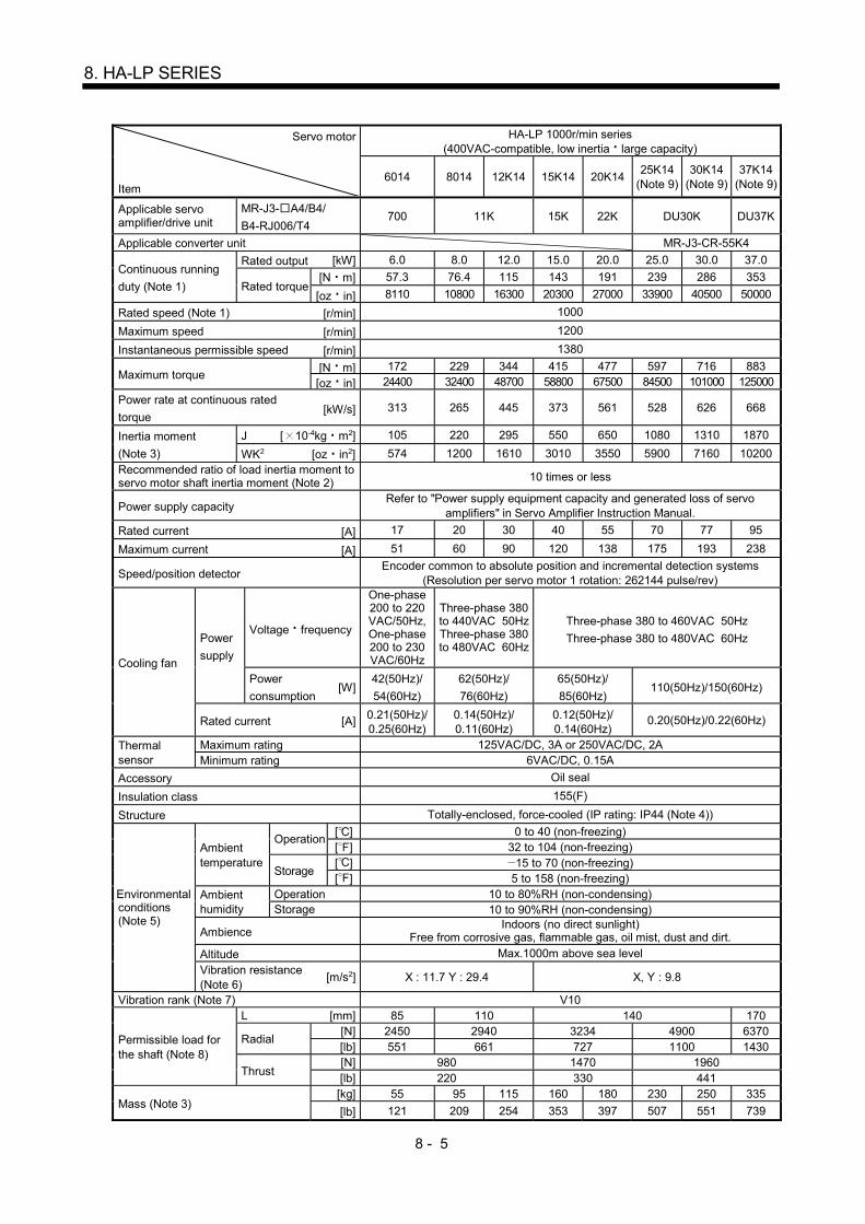
8 - 5
8. HA-LP SERIES
Servo motor
Item
HA-LP 1000r/min series (400VAC-compatible, low inertia large capacity)
6014 8014 12K14 15K14 20K14 25K14
(Note 9) 30K14
(Note 9) 37K14
(Note 9)
Applicable servo amplifier/drive unit
MR-J3- A4/B4/
B4-RJ006/T4 700 11K 15K 22K DU30K DU37K
Applicable converter unit MR-J3-CR-55K4
Continuous running
duty (Note 1)
Rated output [kW] 6.0 8.0 12.0 15.0 20.0 25.0 30.0 37.0
Rated torque [N m] 57.3 76.4 115 143 191 239 286 353
[oz in] 8110 10800 16300 20300 27000 33900 40500 50000
Rated speed (Note 1) [r/min] 1000
Maximum speed [r/min] 1200
Instantaneous permissible speed [r/min] 1380
Maximum torque [N m] 172 229 344 415 477 597 716 883
[oz in] 24400 32400 48700 58800 67500 84500 101000 125000
Power rate at continuous rated
torque [kW/s] 313 265 445 373 561 528 626 668
Inertia moment
(Note 3)
J [ 10-4kg m2] 105 220 295 550 650 1080 1310 1870
WK2 [oz in2] 574 1200 1610 3010 3550 5900 7160 10200 Recommended ratio of load inertia moment to servo motor shaft inertia moment (Note 2) 10 times or less
Power supply capacity Refer to "Power supply equipment capacity and generated loss of servo
amplifiers" in Servo Amplifier Instruction Manual.
Rated current [A] 17 20 30 40 55 70 77 95
Maximum current [A] 51 60 90 120 138 175 193 238
Speed/position detector Encoder common to absolute position and incremental detection systems
(Resolution per servo motor 1 rotation: 262144 pulse/rev)
Cooling fan
Power
supply
Voltage frequency
One-phase 200 to 220 VAC/50Hz, One-phase 200 to 230 VAC/60Hz
Three-phase 380 to 440VAC 50Hz Three-phase 380 to 480VAC 60Hz
Three-phase 380 to 460VAC 50Hz
Three-phase 380 to 480VAC 60Hz
Power
consumption [W]
42(50Hz)/
54(60Hz)
62(50Hz)/
76(60Hz)
65(50Hz)/
85(60Hz) 110(50Hz)/150(60Hz)
Rated current [A] 0.21(50Hz)/ 0.25(60Hz)
0.14(50Hz)/ 0.11(60Hz)
0.12(50Hz)/ 0.14(60Hz)
0.20(50Hz)/0.22(60Hz)
Thermal sensor
Maximum rating 125VAC/DC, 3A or 250VAC/DC, 2A Minimum rating 6VAC/DC, 0.15A
Accessory Oil seal
Insulation class 155(F)
Structure Totally-enclosed, force-cooled (IP rating: IP44 (Note 4))
Environmental conditions (Note 5)
Ambient temperature
Operation [ ] 0 to 40 (non-freezing) [ ] 32 to 104 (non-freezing)
Storage [ ] 15 to 70 (non-freezing) [ ] 5 to 158 (non-freezing)
Ambient humidity
Operation 10 to 80%RH (non-condensing) Storage 10 to 90%RH (non-condensing)
Ambience Indoors (no direct sunlight)
Free from corrosive gas, flammable gas, oil mist, dust and dirt.
Altitude Max.1000m above sea level
Vibration resistance (Note 6)
[m/s2] X : 11.7 Y : 29.4 X, Y : 9.8
Vibration rank (Note 7) V10
Permissible load for the shaft (Note 8)
L [mm] 85 110 140 170
Radial [N] 2450 2940 3234 4900 6370 [lb] 551 661 727 1100 1430
Thrust [N] 980 1470 1960 [lb] 220 330 441
Mass (Note 3) [kg] 55 95 115 160 180 230 250 335
[lb] 121 209 254 353 397 507 551 739

8 - 6
8. HA-LP SERIES
Servo motor
Item
HA-LP 1500r/min series (400VAC-compatible, low inertia large capacity)
701M4 11K1M4 15K1M4 22K1M4 30K1M4 (Note 9)
37K1M4 (Note 9)
45K1M4 (Note 9)
50K1M4 (Note 9)
Applicable servo amplifier/drive unit
MR-J3- A4/B4/ B4-RJ006/T4
700 11K 15K 22K DU30K DU37K DU45K DU55K
Applicable converter unit MR-J3-CR-55K4
Continuous running duty (Note 1)
Rated output [kW] 7.0 11.0 15.0 22.0 30.0 37.0 45.0 50.0
Rated torque [N m] 44.6 70.0 95.5 140 191 236 286 318
[oz in] 6320 9910 13500 19800 27000 33400 40500 45000
Rated speed (Note 1) [r/min] 1500
Maximum speed [r/min] 2000
Instantaneous permissible speed [r/min] 2300
Maximum torque [N m] 134 210 286 350 477 589 716 796
[oz in] 19000 29700 40500 49600 67500 83400 101000 113000
Power rate at continuous rated torque
[kW/s] 189 223 309 357 561 514 626 542
Inertia moment (Note 3)
J [ 10-4kg m2] 105 220 295 550 650 1080 1310 1870
WK2 [oz in2] 574 1200 1610 3010 3550 5900 7160 10200 Recommended ratio of load inertia moment to servo motor shaft inertia moment (Note 2)
10 times or less
Power supply capacity Refer to "Power supply equipment capacity and generated loss of servo
amplifiers" in Servo Amplifier Instruction Manual.
Rated current [A] 18 31 41 63 87 101 128 143
Maximum current [A] 54 93 123 158 218 253 320 358
Speed/position detector Encoder common to absolute position and incremental detection systems
(Resolution per servo motor 1 rotation: 262144 pulse/rev)
Cooling fan
Power supply
Voltage frequency
One-phase 200 to 220 VAC/50Hz, One-phase 200 to 230 VAC/60Hz
Three-phase 380 to 440VAC 50Hz Three-phase 380 to 480VAC 60Hz
Three-phase 380 to 460VAC 50Hz Three-phase 380 to 480VAC 60Hz
Power consumption
[W] 42(50Hz)/ 54(60Hz)
62(50Hz)/ 76(60Hz)
65 (50Hz)/ 85 (60 Hz)
110(50Hz)/ 150(60Hz)
Rated current [A] 0.21(50Hz) 0.25(60Hz)
0.14(50Hz) 0.11(60Hz)
0.12 (50Hz)/ 0.14 (60 Hz)
0.20(50Hz)/0.22(60Hz)
Thermal sensor
Maximum rating 125VAC/DC, 3A or 250VAC/DC, 2A
Minimum rating 6VAC/DC, 0.15A
Accessory Oil seal
Insulation class 155(F)
Structure Totally-enclosed, force-cooled (IP rating: IP44 (Note 4))
Environmental conditions (Note 5)
Ambient temperature
Operation [ ] 0 to 40 (non-freezing)
[ ] 32 to 104 (non-freezing)
Storage [ ] 15 to 70 (non-freezing)
[ ] 5 to 158 (non-freezing)
Ambient humidity
Operation 10 to 80%RH (non-condensing)
Storage 10 to 90%RH (non-condensing)
Ambience Indoors (no direct sunlight)
Free from corrosive gas, flammable gas, oil mist, dust and dirt. Altitude Max.1000m above sea level
Vibration resistance (Note 6)
[m/s2] X : 11.7, Y : 29.4 X, Y : 9.8
Vibration rank (Note 7) V10
Permissible load for the shaft (Note 8)
L [mm] 85 110 140 170
Radial [N] 2450 2940 3234 4900 6370
[lb] 551 661 727 1100 1430
Thrust [N] 980 1470 1960
[lb] 220 330 441
Mass (Note 3) [kg] 55 95 115 160 180 230 250 335
[lb] 121 209 254 353 397 507 551 739
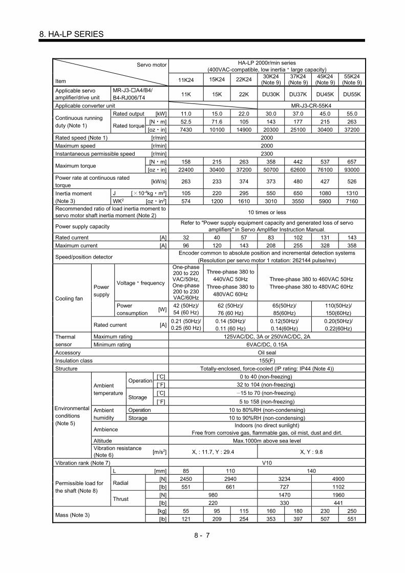
8 - 7
8. HA-LP SERIES
Servo motor
Item
HA-LP 2000r/min series (400VAC-compatible, low inertia large capacity)
11K24 15K24 22K24 30K24 (Note 9)
37K24 (Note 9)
45K24 (Note 9)
55K24 (Note 9)
Applicable servo amplifier/drive unit
MR-J3- A4/B4/ B4-RJ006/T4
11K 15K 22K DU30K DU37K DU45K DU55K
Applicable converter unit MR-J3-CR-55K4
Continuous running duty (Note 1)
Rated output [kW] 11.0 15.0 22.0 30.0 37.0 45.0 55.0
Rated torque [N m] 52.5 71.6 105 143 177 215 263
[oz in] 7430 10100 14900 20300 25100 30400 37200
Rated speed (Note 1) [r/min] 2000
Maximum speed [r/min] 2000
Instantaneous permissible speed [r/min] 2300
Maximum torque [N m] 158 215 263 358 442 537 657
[oz in] 22400 30400 37200 50700 62600 76100 93000
Power rate at continuous rated torque
[kW/s] 263 233 374 373 480 427 526
Inertia moment (Note 3)
J [ 10-4kg m2] 105 220 295 550 650 1080 1310
WK2 [oz in2] 574 1200 1610 3010 3550 5900 7160 Recommended ratio of load inertia moment to servo motor shaft inertia moment (Note 2)
10 times or less
Power supply capacity Refer to "Power supply equipment capacity and generated loss of servo
amplifiers" in Servo Amplifier Instruction Manual.
Rated current [A] 32 40 57 83 102 131 143
Maximum current [A] 96 120 143 208 255 328 358
Speed/position detector Encoder common to absolute position and incremental detection systems
(Resolution per servo motor 1 rotation: 262144 pulse/rev)
Cooling fan
Power supply
Voltage frequency
One-phase 200 to 220 VAC/50Hz, One-phase 200 to 230 VAC/60Hz
Three-phase 380 to 440VAC 50Hz
Three-phase 380 to 480VAC 60Hz
Three-phase 380 to 460VAC 50Hz Three-phase 380 to 480VAC 60Hz
Power consumption
[W] 42 (50Hz)/ 54 (60 Hz)
62 (50Hz)/ 76 (60 Hz)
65(50Hz)/ 85(60Hz)
110(50Hz)/ 150(60Hz)
Rated current [A] 0.21 (50Hz)/ 0.25 (60 Hz)
0.14 (50Hz)/ 0.11 (60 Hz)
0.12(50Hz)/ 0.14(60Hz)
0.20(50Hz)/ 0.22(60Hz)
Thermal sensor
Maximum rating 125VAC/DC, 3A or 250VAC/DC, 2A
Minimum rating 6VAC/DC, 0.15A
Accessory Oil seal
Insulation class 155(F)
Structure Totally-enclosed, force-cooled (IP rating: IP44 (Note 4))
Environmental conditions (Note 5)
Ambient temperature
Operation [ ] 0 to 40 (non-freezing)
[ ] 32 to 104 (non-freezing)
Storage [ ] 15 to 70 (non-freezing)
[ ] 5 to 158 (non-freezing)
Ambient humidity
Operation 10 to 80%RH (non-condensing)
Storage 10 to 90%RH (non-condensing)
Ambience Indoors (no direct sunlight)
Free from corrosive gas, flammable gas, oil mist, dust and dirt.
Altitude Max.1000m above sea level Vibration resistance (Note 6)
[m/s2] X, : 11.7, Y : 29.4 X, Y : 9.8
Vibration rank (Note 7) V10
Permissible load for the shaft (Note 8)
L [mm] 85 110 140
Radial [N] 2450 2940 3234 4900
[lb] 551 661 727 1102
Thrust [N] 980 1470 1960
[lb] 220 330 441
Mass (Note 3) [kg] 55 95 115 160 180 230 250
[lb] 121 209 254 353 397 507 551

8 - 8
8. HA-LP SERIES
Note 1. When the power supply voltage drops, the output and the rated speed cannot be guaranteed.
2. If the load inertia moment ratio exceeds the indicated value, please contact your local sales office.
3. Refer to the outline dimension drawing for the servo motor with an electromagnetic brake.
4. Except for the shaft – through portion.
5. In the environment where the servo motor is exposed to oil mist, oil and/or water, the servo motor of the standard specifications
may not be usable. Please contact your local sales office.
6. The vibration direction is as shown in the figure. The value is the one at the part that indicates the maximum value (normally the
opposite-to-load side bracket). When the servo motor stops, fretting is likely to occur at the bearing. Therefore, suppress the
vibration to about half of the permissible value.
YX
Servo motor
Vibration Vib
ratio
n am
plitu
de
(bot
h am
plit
udes
) [
m]
Speed [r/min]0 1000 2000
10
100
1000
7. V10 indicates that the amplitude of a single servo motor is 10 m or less. The following figure shows the servo motor installation
position for measurement and the measuring position.
Servo motor
Top
Bottom
Measuring position
8. For the symbols in the table, refer to the following diagram: Do not subject the shaft to load greater than this value.
The values in the table assume that the loads work singly.
LRadial load
Thrust load
L: Distance from flange mounting surface to load center
9. Not compliant with servo amplifiers MR-J3- B-RJ006 and MR-J3- T.
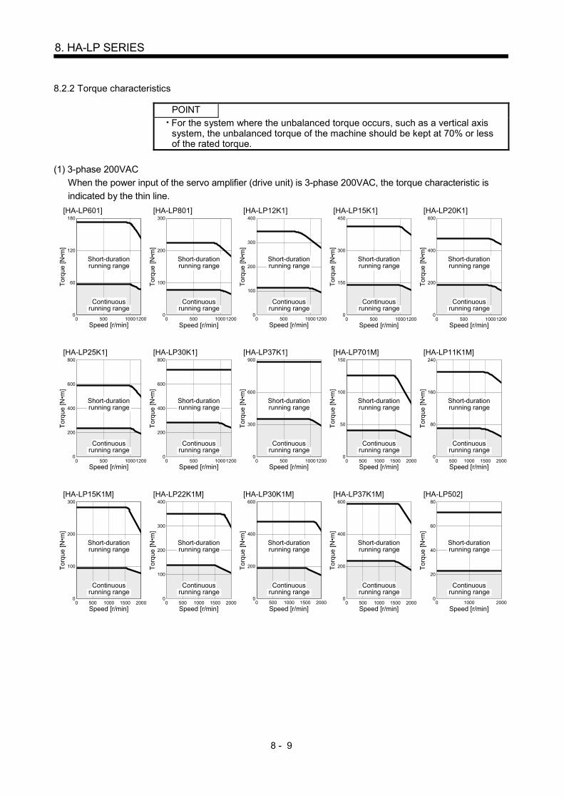
8 - 9
8. HA-LP SERIES
8.2.2 Torque characteristics
POINT
For the system where the unbalanced torque occurs, such as a vertical axis system, the unbalanced torque of the machine should be kept at 70% or less of the rated torque.
(1) 3-phase 200VAC
When the power input of the servo amplifier (drive unit) is 3-phase 200VAC, the torque characteristic is
indicated by the thin line.
500 1000120000
[HA-LP601]
60
120
180
Speed [r/min]
Continuousrunning range
Short-durationrunning range
Tor
que
[N•m
]
[HA-LP801]
500 1000120000
100
200
300
Speed [r/min]
Continuousrunning range
Short-durationrunning range
Tor
que
[N•m
]
[HA-LP12K1]
500 1000120000
100
200
400
300
Speed [r/min]
Continuousrunning range
Short-durationrunning range
Tor
que
[N•m
]
500 100012000
0
[HA-LP15K1]
150
450
300
Speed [r/min]
Continuousrunning range
Short-durationrunning range
Tor
que
[N•m
]
[HA-LP20K1]
500 1000120000
200
600
400
Speed [r/min]
Continuousrunning range
Short-durationrunning range
Tor
que
[N•m
]
[HA-LP25K1]
500 1000120000
200
800
400
600
Speed [r/min]
Continuousrunning range
Short-durationrunning range
Tor
que
[N•m
]
[HA-LP30K1]
500 1000120000
200
800
400
600
Speed [r/min]
Continuousrunning range
Short-durationrunning range
Tor
que
[N•m
]
[HA-LP37K1]
500 1000120000
300
900
600
Speed [r/min]
Continuousrunning range
Short-durationrunning range
Tor
que
[N•m
]
[HA-LP701M]
500 1000 1500 200000
50
100
150
Speed [r/min]
Continuousrunning range
Short-durationrunning range
Tor
que
[N•m
]
[HA-LP11K1M]
500 1000 1500 200000
80
160
240
Speed [r/min]
Continuousrunning range
Short-durationrunning range
Tor
que
[N•m
]
[HA-LP15K1M]
500 1000 1500 200000
100
200
300
Speed [r/min]
Continuousrunning range
Short-durationrunning range
Tor
que
[N•m
]
[HA-LP22K1M]
500 1000 1500 200000
100
200
400
300
Speed [r/min]
Continuousrunning range
Short-durationrunning range
Tor
que
[N•m
]
[HA-LP30K1M]
500 1000 1500 200000
200
400
600
Speed [r/min]
Continuousrunning range
Short-durationrunning range
Tor
que
[N•m
]
[HA-LP37K1M]
500 1000 1500 200000
200
400
600
Speed [r/min]
Continuousrunning range
Short-durationrunning range
Tor
que
[N•m
]
[HA-LP502]
1000 200000
20
40
80
60
Speed [r/min]
Continuousrunning range
Short-durationrunning range
Tor
que
[N•m
]
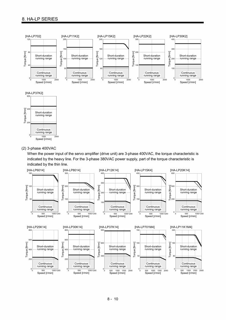
8 - 10
8. HA-LP SERIES
[HA-LP702]
1000 200000
40
120
80
Speed [r/min]
Continuousrunning range
Short-durationrunning range
Tor
que
[N•m
]
[HA-LP11K2]
1000 200000
50
100
200
150
Speed [r/min]
Continuousrunning range
Short-durationrunning range
Tor
que
[N•m
]
[HA-LP15K2]
1000 200000
60
120
240
180
Speed [r/min]
Continuousrunning range
Short-durationrunning range
Tor
que
[N•m
]
[HA-LP22K2]
1000 200000
100
300
200
Speed [r/min]
Continuousrunning range
Short-durationrunning range
Tor
que
[N•m
]
1000 20000
0
[HA-LP30K2]
100
200
400
300
Speed [r/min]
Continuousrunning range
Short-durationrunning range
Tor
que
[N•m
]
[HA-LP37K2]
1000 200000
200
600
400
Speed [r/min]
Continuousrunning range
Short-durationrunning range
Tor
que
[N•m
]
(2) 3-phase 400VAC
When the power input of the servo amplifier (drive unit) are 3-phase 400VAC, the torque characteristic is
indicated by the heavy line. For the 3-phase 380VAC power supply, part of the torque characteristic is
indicated by the thin line.
[HA-LP6014]
500 1000120000
60
120
180
Speed [r/min]
Continuousrunning range
Short-durationrunning range
Tor
que
[N•m
]
[HA-LP8014]
500 1000120000
100
200
300
Speed [r/min]
Continuousrunning range
Short-durationrunning range
Tor
que
[N•m
]
[HA-LP12K14]
500 1000120000
200
300
400
100
Speed [r/min]
Continuousrunning range
Short-durationrunning range
Tor
que
[N•m
]
[HA-LP15K4]
500 1000120000
150
300
450
Speed [r/min]
Continuousrunning range
Short-durationrunning range
Tor
que
[N•m
]
[HA-LP20K14]
500 1000120000
200
400
600
Speed [r/min]
Continuousrunning range
Short-durationrunning range
Tor
que
[N•m
]
[HA-LP25K14]
500 1000120000
200
800
400
600
Speed [r/min]
Continuousrunning range
Short-durationrunning range
Tor
que
[N•m
]
[HA-LP30K14]
500 1000120000
200
400
800
600
Speed [r/min]
Continuousrunning range
Short-durationrunning range
Tor
que
[N•m
]
[HA-LP37K14]
500 1000 1500 200000
300
900
600
Speed [r/min]
Continuousrunning range
Short-durationrunning range
Tor
que
[N•m
]
[HA-LP701M4]
500 1000 1500 200000
50
100
150
Speed [r/min]
Continuousrunning range
Short-durationrunning range
Tor
que
[N•m
]
[HA-LP11K1M4]
500 1000 1500 200000
80
160
240
Speed [r/min]
Continuousrunning range
Short-durationrunning range
Tor
que
[N•m
]
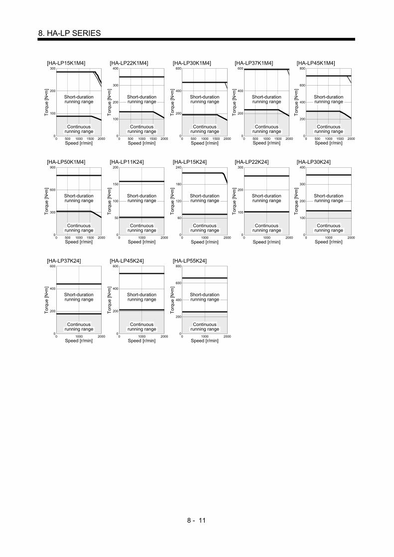
8 - 11
8. HA-LP SERIES
[HA-LP15K1M4]
500 1000 1500 200000
100
200
300
Speed [r/min]
Continuousrunning range
Short-durationrunning range
Tor
que
[N•m
]
[HA-LP22K1M4]
500 1000 1500 200000
200
300
400
100
Speed [r/min]
Continuousrunning range
Short-durationrunning range
Tor
que
[N•m
]
[HA-LP30K1M4]
500 1000 1500 200000
200
400
600
Speed [r/min]
Continuousrunning range
Short-durationrunning range
Tor
que
[N•m
]
[HA-LP37K1M4]
500 1000 1500 200000
200
400
600
Speed [r/min]
Continuousrunning range
Short-durationrunning range
Tor
que
[N•m
]
[HA-LP45K1M4]
500 1000 1500 200000
200
600
800
400
Speed [r/min]
Continuousrunning range
Short-durationrunning range
Tor
que
[N•m
]
[HA-LP50K1M4]
500 1000 1500 200000
300
600
900
Speed [r/min]
Continuousrunning range
Short-durationrunning range
Tor
que
[N•m
]
[HA-LP11K24]
1000 200000
50
200
100
150
Speed [r/min]
Continuousrunning range
Short-durationrunning range
Tor
que
[N•m
]
[HA-LP15K24]
1000 200000
60
240
120
180
Speed [r/min]
Continuousrunning range
Short-durationrunning range
Tor
que
[N•m
]
[HA-LP22K24]
1000 200000
100
300
200
Speed [r/min]
Continuousrunning range
Short-durationrunning range
Tor
que
[N•m
]
1000 20000
0
[HA-LP30K24]
100
400
200
300
Speed [r/min]
Continuousrunning range
Short-durationrunning range
Tor
que
[N•m
]
[HA-LP37K24]
1000 200000
200
600
400
Speed [r/min]
Continuousrunning range
Short-durationrunning range
Tor
que
[N•m
]
[HA-LP45K24]
1000 200000
200
600
400
Speed [r/min]
Continuousrunning range
Short-durationrunning range
Tor
que
[N•m
]
[HA-LP55K24]
1000 200000
200
800
600
400
Speed [r/min]
Continuousrunning range
Short-durationrunning range
Tor
que
[N•m
]
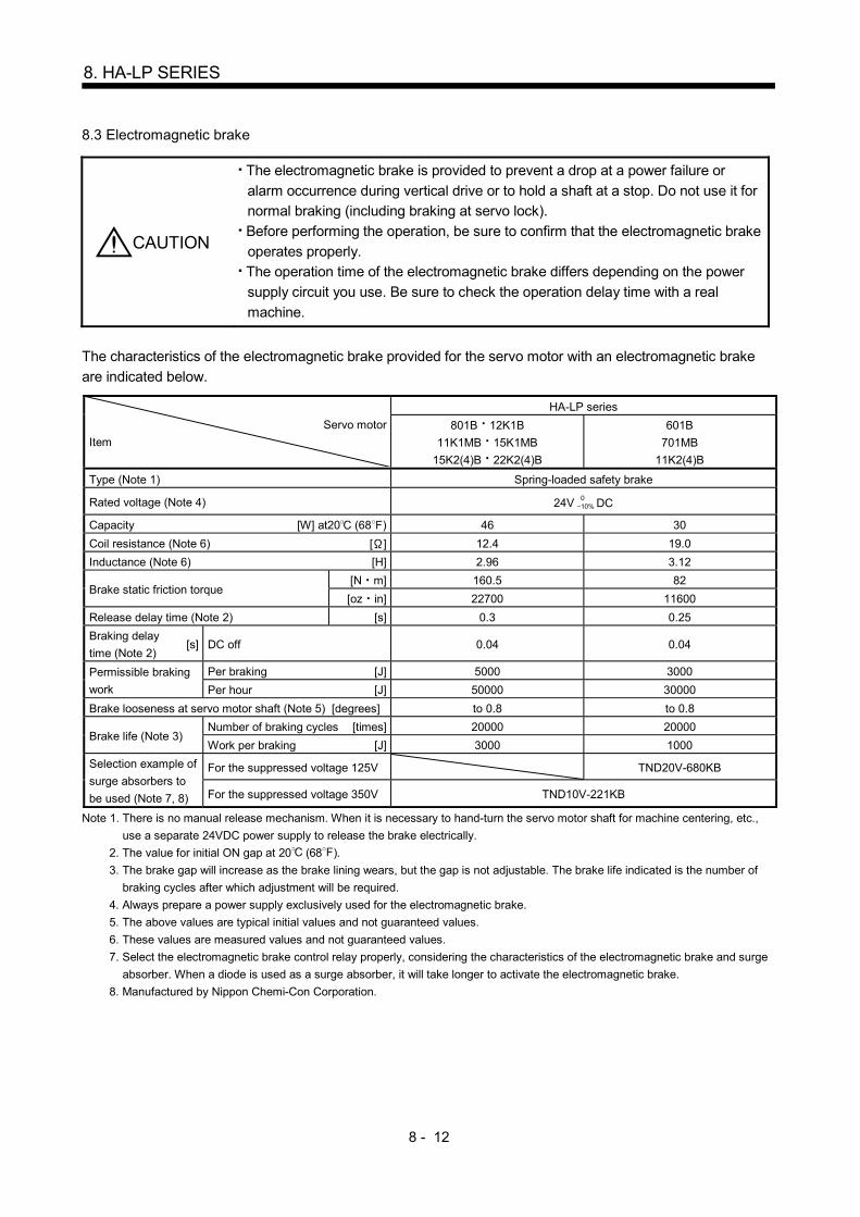
8 - 12
8. HA-LP SERIES
8.3 Electromagnetic brake
CAUTION
The electromagnetic brake is provided to prevent a drop at a power failure or
alarm occurrence during vertical drive or to hold a shaft at a stop. Do not use it for
normal braking (including braking at servo lock).
Before performing the operation, be sure to confirm that the electromagnetic brake
operates properly.
The operation time of the electromagnetic brake differs depending on the power
supply circuit you use. Be sure to check the operation delay time with a real
machine.
The characteristics of the electromagnetic brake provided for the servo motor with an electromagnetic brake
are indicated below.
Servo motor
Item
HA-LP series
801B 12K1B
11K1MB 15K1MB
15K2(4)B 22K2(4)B
601B
701MB
11K2(4)B
Type (Note 1) Spring-loaded safety brake
Rated voltage (Note 4) 24V 010% DC
Capacity [W] at20 (68 ) 46 30
Coil resistance (Note 6) [ ] 12.4 19.0
Inductance (Note 6) [H] 2.96 3.12
Brake static friction torque [N m] 160.5 82
[oz in] 22700 11600
Release delay time (Note 2) [s] 0.3 0.25
Braking delay
time (Note 2) [s] DC off 0.04 0.04
Permissible braking
work
Per braking [J] 5000 3000
Per hour [J] 50000 30000
Brake looseness at servo motor shaft (Note 5) [degrees] to 0.8 to 0.8
Brake life (Note 3) Number of braking cycles [times] 20000 20000
Work per braking [J] 3000 1000
Selection example of
surge absorbers to
be used (Note 7, 8)
For the suppressed voltage 125V TND20V-680KB
For the suppressed voltage 350V TND10V-221KB
Note 1. There is no manual release mechanism. When it is necessary to hand-turn the servo motor shaft for machine centering, etc.,
use a separate 24VDC power supply to release the brake electrically.
2. The value for initial ON gap at 20 (68 ).
3. The brake gap will increase as the brake lining wears, but the gap is not adjustable. The brake life indicated is the number of
braking cycles after which adjustment will be required.
4. Always prepare a power supply exclusively used for the electromagnetic brake.
5. The above values are typical initial values and not guaranteed values.
6. These values are measured values and not guaranteed values.
7. Select the electromagnetic brake control relay properly, considering the characteristics of the electromagnetic brake and surge
absorber. When a diode is used as a surge absorber, it will take longer to activate the electromagnetic brake.
8. Manufactured by Nippon Chemi-Con Corporation.
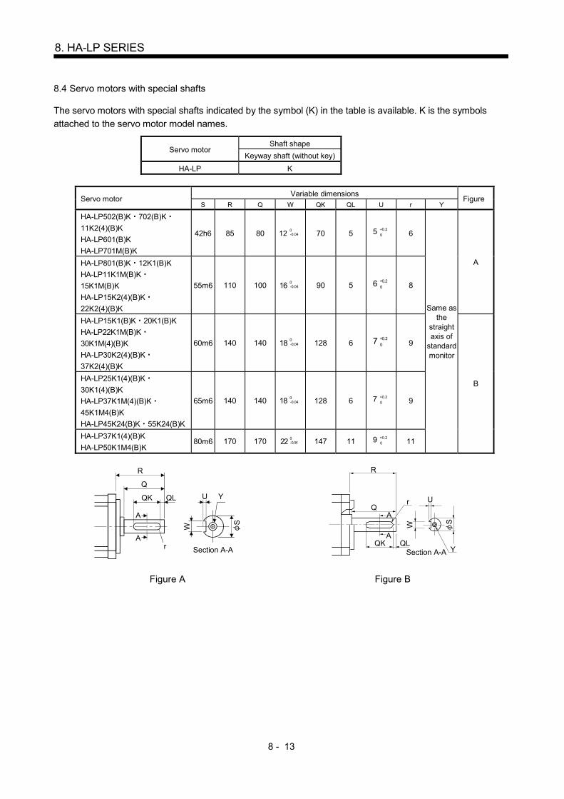
8 - 13
8. HA-LP SERIES
8.4 Servo motors with special shafts
The servo motors with special shafts indicated by the symbol (K) in the table is available. K is the symbols
attached to the servo motor model names.
Servo motor Shaft shape
Keyway shaft (without key)
HA-LP K
Servo motor Variable dimensions
Figure S R Q W QK QL U r Y
HA-LP502(B)K 702(B)K 11K2(4)(B)K
HA-LP601(B)K
HA-LP701M(B)K
42h6 85 80 120-0.04 70 5 5 0
+0.2
6
Same as the
straight axis of
standard monitor
A HA-LP801(B)K 12K1(B)K
HA-LP11K1M(B)K 15K1M(B)K
HA-LP15K2(4)(B)K 22K2(4)(B)K
55m6 110 100 160-0.04 90 5 6 0
+0.2
8
HA-LP15K1(B)K 20K1(B)K
HA-LP22K1M(B)K 30K1M(4)(B)K
HA-LP30K2(4)(B)K 37K2(4)(B)K
60m6 140 140 180-0.04 128 6 7 0
+0.2
9
B HA-LP25K1(4)(B)K 30K1(4)(B)K
HA-LP37K1M(4)(B)K 45K1M4(B)K
HA-LP45K24(B)K 55K24(B)K
65m6 140 140 18 0-0.04 128 6 7
0
+0.2
9
HA-LP37K1(4)(B)K
HA-LP50K1M4(B)K 80m6 170 170 22
0-0.04 147 11 9
0
+0.2
11
QK
A
Q
R
A
QL U
W
r
Y
S
Section A-A
Q
R
QK
A
A
r
QL
W S
U
Y
Figure A Figure B
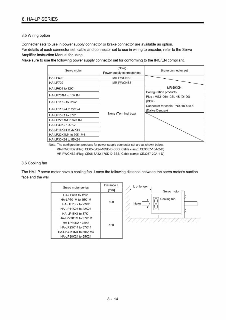
8 - 14
8. HA-LP SERIES
8.5 Wiring option
Connecter sets to use in power supply connector or brake connector are available as option.
For details of each connector set, cable and connector set to use in wiring to encoder, refer to the Servo
Amplifier Instruction Manual for using.
Make sure to use the following power supply connector set for conforming to the INC/EN compliant.
Servo motor (Note)
Power supply connector set Brake connector set
HA-LP502 MR-PWCNS2
HA-LP702 MR-PWCNS3
HA-LP601 to 12K1
None (Terminal box)
MR-BKCN
Configuration products
Plug : MS3106A10SL-4S (D190)
(DDK)
Connector for cable : YSO10-5 to 8
(Daiwa Dengyo)
HA-LP701M to 15K1M
HA-LP11K2 to 22K2
HA-LP11K24 to 22K24
HA-LP15K1 to 37K1
HA-LP22K1M to 37K1M
HA-LP30K2 37K2
HA-LP15K14 to 37K14
HA-LP22K1M4 to 50K1M4
HA-LP30K24 to 55K24
Note. The configuration products for power supply connector set are as shown below.
MR-PWCNS2 (Plug: CE05-6A24-10SD-D-BSS Cable clamp: CE3057-16A-2-D)
MR-PWCNS3 (Plug: CE05-6A32-17SD-D-BSS Cable clamp: CE3057-20A-1-D)
8.6 Cooling fan
The HA-LP servo motor have a cooling fan. Leave the following distance between the servo motor's suction
face and the wall.
Servo motor series Distance L L or longer
Servo motor
Cooling fan
Intake
[mm]
HA-LP601 to 12K1
HA-LP701M to 15K1M
HA-LP11K2 to 22K2
HA-LP11K24 to 22K24
100
HA-LP15K1 to 37K1
HA-LP22K1M to 37K1M
HA-LP30K2 37K2
HA-LP25K14 to 37K14
HA-LP30K1M4 to 50K1M4
HA-LP30K24 to 55K24
150

8 - 15
8. HA-LP SERIES
8.7 Outline dimension drawings
The dimensions without tolerances are reference dimensions.
Inertia moment on the table is the value calculated by converting the total value of inertia moment for servo
motor, electromagnetic brake and decelerator with servo motor shaft. 8.7.1 Terminal box detail diagram
(1) HA-LP601(4) 701M(4) 11K2(4)
[Unit: mm]
Thermal sensor terminal
(OHS1 OHS2) M4 screw
Cooling fan terminal block
(BU BV) M4 screw
Encoder connector
CM10-R10P
Earth terminal( )M6 screw
Motor power supplyterminal block
(U V W) M6 screw
146
(2) HA-LP801(4) 12K1(4) 11K1M(4) 15K1M(4) 15K2(4) 22K2(4)
[Unit: mm]
180
Thermal sensor terminal
(OHS1 OHS2) M4 screw
Cooling fan terminal block
(BU BV) M4 screw
Encoder connector
CM10-R10P
Motor power supplyterminal block
(U V W) M8 screw
Earth terminal( )M6 screw
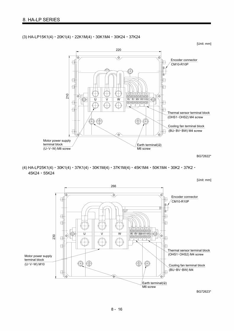
8 - 16
8. HA-LP SERIES
(3) HA-LP15K1(4) 20K1(4) 22K1M(4) 30K1M4 30K24 37K24
[Unit: mm]
BG72622*
220
Cooling fan terminal block
Motor power supplyterminal block
(BU BV BW) M4 screw
(U V W) M8 screw
CM10-R10P
Encoder connector
Thermal sensor terminal block
(OHS1 OHS2) M4 screw
Earth terminal( )M6 screw
(4) HA-LP25K1(4) 30K1(4) 37K1(4) 30K1M(4) 37K1M(4) 45K1M4 50K1M4 30K2 37K2
45K24 55K24
[Unit: mm]
BG72623*
266
Encoder connector
CM10-R10P
Thermal sensor terminal block
Cooling fan terminal block
Motor power supplyterminal block
(OHS1 OHS2) M4 screw
(BU BV BW) M4
(U V W) M10
Earth terminal( )M6 screw

8 - 17
8. HA-LP SERIES
8.7.2 Standard (without an electromagnetic brake)
Model Output
[kW]
Inertia moment
J [ 10-4kg m2](WK2 [oz in2])
Mass
[kg] ([lb])
HA-LP502 5 74 (405) 28 (61.7)
[Unit: mm]
M8 screw
19.8 5.2
CE05-2A24-10P
Power supply connector
CM10-R10P
13
20 3
80
85
225
298
2
15
250
45
60
200
S50689B U
VW
BC29958*
Encoder connector
Motor plate, Caution plate
Hanger
Power supply connector layout
Motor flange direction
4- 14.5 mounting hole
Use hexagon socket
head cap screw
Motor plate Caution plate
Top Bottom
Oil seal
Top
Bottom
A
ED
FG
BC
Caution plate (Earth)
Model Output
[kW]
Inertia moment
J [ 10-4kg m2](WK2 [oz in2])
Mass
[kg] ([lb])
HA-LP702 7 94.2 (515) 35 (77.2)
[Unit: mm]
ABDC
W
V U
M8 screw
19.8 5.2
CE05-2A32-17P
CM10-R10P
13
20 3
80
85
267
340
45
60
200
S50689BCaution plate
Encoder connector
Power supply connector
Motor plate, Caution plate
Oil seal
Power supply connector layout
Motor flange direction
250
2
15
4- 14.5 mounting hole
Use hexagon socket
head cap screw
Motor plate Caution plate
Top Bottom
Hanger
Top
BC29959*
Bottom
(Earth)
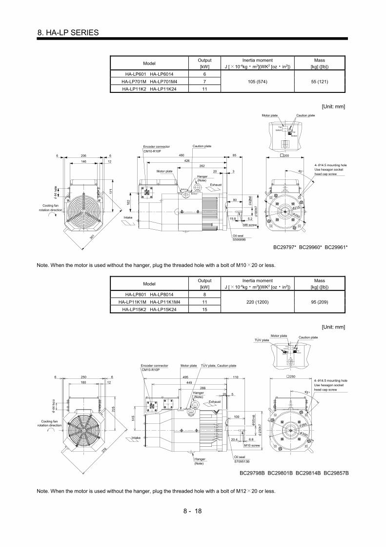
8 - 18
8. HA-LP SERIES
Model Output
[kW]
Inertia moment
J [ 10-4kg m2](WK2 [oz in2])
Mass
[kg] ([lb])
HA-LP601 HA-LP6014 6
105 (574) 55 (121) HA-LP701M HA-LP701M4 7
HA-LP11K2 HA-LP11K24 11
[Unit: mm]
20
262
426
480
12
2066
146
6
CM10-R10P
Top
BottomTop
200
45
215
85
250
S50689B
80
3
5.219.8
M8 screw
Oil seal
Encoder connector
Motor plate
Caution plate
4- 14.5 mounting holeUse hexagon socket
head cap screwHanger
301
Top
Top
Bottom
Bottom
Motor plate Caution plate
Bottom
BC29797* BC29960* BC29961*
(Note)
Intake
Exhaust
Cooling fan
rotation direction
Note. When the motor is used without the hanger, plug the threaded hole with a bolt of M10 20 or less.
Model Output
[kW]
Inertia moment
J [ 10-4kg m2](WK2 [oz in2])
Mass
[kg] ([lb])
HA-LP801 HA-LP8014 8
220 (1200) 95 (209) HA-LP11K1M HA-LP11K1M4 11
HA-LP15K2 HA-LP15K24 15
[Unit: mm]
BC29798B BC29801B BC29814B BC29857B
12
250
180
6
286
6 110
100
449
525
376
6.620.4
. .TUV plate
. .TUV plate, Caution plate
495 250
300
265
M10 screw
S709513B
CM10-R10P
Cooling fanrotation direction
Intake
Encoder connector Motor plate
Hanger(Note)
Hanger(Note)
Exhaust
Top
Top
Top
Bottom
Bottom
Bottom
Oil seal
4- 14.5 mounting holeUse hexagon sockethead cap screw
Motor plate Caution plate
Top BottomTop Bottom
45
Note. When the motor is used without the hanger, plug the threaded hole with a bolt of M12 20 or less.

8 - 19
8. HA-LP SERIES
Model Output
[kW]
Inertia moment
J [ 10-4kg m2](WK2 [oz in2])
Mass
[kg] ([lb])
HA-LP12K1 HA-LP12K14 12
295 (1610) 115 (254) HA-LP15K1M HA-LP15K1M4 15
HA-LP22K2 HA-LP22K24 22
[Unit: mm]
BC29799B BC29802B BC29815B BC29816B BC29818A BC29819A
555
12
250
180
6
346
6
509
376
100
110
525
6.620.4
300
265
M10 screw
S709513B
CM10-R10P
Cooling fanrotation direction
Intake
Encoder connector Motor plate
Hanger(Note)
Hanger(Note)
Exhaust
Oil seal
4- 14.5 mounting holeUse hexagon sockethead cap screw
Motor plate Caution plate
TopTop
Bottom
Bottom
Top
Top
Top
Bottom
Bottom
Bottom
. .TUV plate
. .TUV plate, Caution plate
250
45
Note. When the motor is used without the hanger, plug the threaded hole with a bolt of M12 20 or less.
Model Output
[kW]
Inertia moment
J [ 10-4kg m2](WK2 [oz in2])
Mass
[kg] ([lb])
HA-LP15K1 HA-LP15K14 15
550 (3010) 160 (353) HA-LP22K1M HA-LP22K1M4 22
HA-LP30K24 30
[Unit: mm]
140
14066
105
260 4- 15
108105
25 8
12220
286 605
386
426
51
128
25 5
310
BC29858* BC29863* BC30386B
12712755
350 3
00
M12 screw
S659013B
CM10-R10P
Cooling fanrotation direction
Intake
Encoder connector Motor plate Caution plate
Hanger(Note)
Exhaust
Oil seal
4- 19 mounting hole
Use hexagon sockethead cap screw
Motor plate Caution plate
Top
Top
BottomBottom
Top
Top
Bottom
Bottom
280
45
Note. When the motor is used without the hanger, plug the threaded hole with a bolt of M16 20 or less.

8 - 20
8. HA-LP SERIES
Model Output
[kW]
Inertia moment
J [ 10-4kg m2](WK2 [oz in2])
Mass
[kg] ([lb])
HA-LP20K1 HA-LP20K14 20
650 (3550) 180 (397) HA-LP30K1M4 30
HA-LP37K24 37
[Unit: mm]
140
14066
127
304
108127
25 8
12220
286 650
431
471128
25 5
310
127
BC29864* BC30384* BC30388B
12755
350 300
M12 screw
S659013B
CM10-R10P
Cooling fanrotation direction
Intake
Encoder connector
Motor plate Caution plate
Hanger(Note)
Exhaust
Oil seal
4- 19 mounting holeUse hexagon sockethead cap screw
Motor plate Caution plate
TopTop
BottomBottom
Top
Top
Bottom
Bottom
280
45
4- 15
51
Note. When the motor is used without the hanger, plug the threaded hole with a bolt of M16 20 or less.
Model Output
[kW]
Inertia moment
J [ 10-4kg m2](WK2 [oz in2])
Mass
[kg] ([lb])
HA-LP25K1 HA-LP25K14 25
1080 (5900) 230 (507) HA-LP37K1M HA-LP37K1M4 37
HA-LP45K24 45
[Unit: mm]
121
262
25
640
439
399
6 6
101.5101.5
266
352
13812
140
140
30 9
349
BC29865* BC30394* BC30397B
139.5 139.5
70
5
400 350
M16 screw
S709513B
CM10-R10P
Cooling fanrotation direction
Intake
Encoder connector
Hanger
(Note)
Exhaust
Oil seal
4- 19 mounting holeUse hexagon socket
head cap screw
Motor plate Caution plate
Motor plate Caution plate
Top
Top
Bottom
Bottom
Top
Top
Bottom
Bottom
350
45
4- 19
63
Note. When the motor is used without the hanger, plug the threaded hole with a bolt of M16 20 or less.

8 - 21
8. HA-LP SERIES
Model Output
[kW]
Inertia moment
J [ 10-4kg m2](WK2 [oz in2])
Mass
[kg] ([lb])
HA-LP30K1 HA-LP30K14 30
1310 (7160) 250 (551) HA-LP45K1M4 45
HA-LP55K24 55
[Unit: mm]
121
300
25
685
484
444
6 6
120.5120.5
266
352
13812
140
140
30 9
349
139.5 139.5
BC30390* BC30396* BC30399B
70
5
400 350
M16 screw
S709513B
CM10-R10P
Cooling fanrotation direction
Intake
Encoder connector Motor plate Caution plate
Hanger
(Note)
Exhaust
Oil seal
4- 19 mounting holeUse hexagon socket
head cap screw
Motor plate Caution plate
TopTop
BottomBottom
Top
Top
Bottom
Bottom
350
45
4- 19
63
Note. When the motor is used without the hanger, plug the threaded hole with a bolt of M12 20 or less.
Model Output
[kW]
Inertia moment
J [ 10-4kg m2](WK2 [oz in2])
Mass
[kg] ([lb])
HA-LP37K1 HA-LP37K14 37 1870 (10200) 335 (739)
HA-LP50K1M4 50
[Unit: mm]
121
412
25
785
584
544
6 6
178178
266
352
13812
170
30 9
349
139.5
BC30392* BC30398B
70
5
170
400
350
M16 screw
S8511013B
CM10-R10P
Cooling fanrotation direction
Intake
Encoder connector
Motor plate Caution plate
Hanger(Note)
Exhaust
Oil seal
4- 19 mounting hole
Use hexagon sockethead cap screw
Motor plate Caution plate
Top
Top
Bottom
Bottom
Top
Top
Bottom
Bottom
350
45
4- 24
63
Note. When the motor is used without the hanger, plug the threaded hole with a bolt of M16 20 or less.
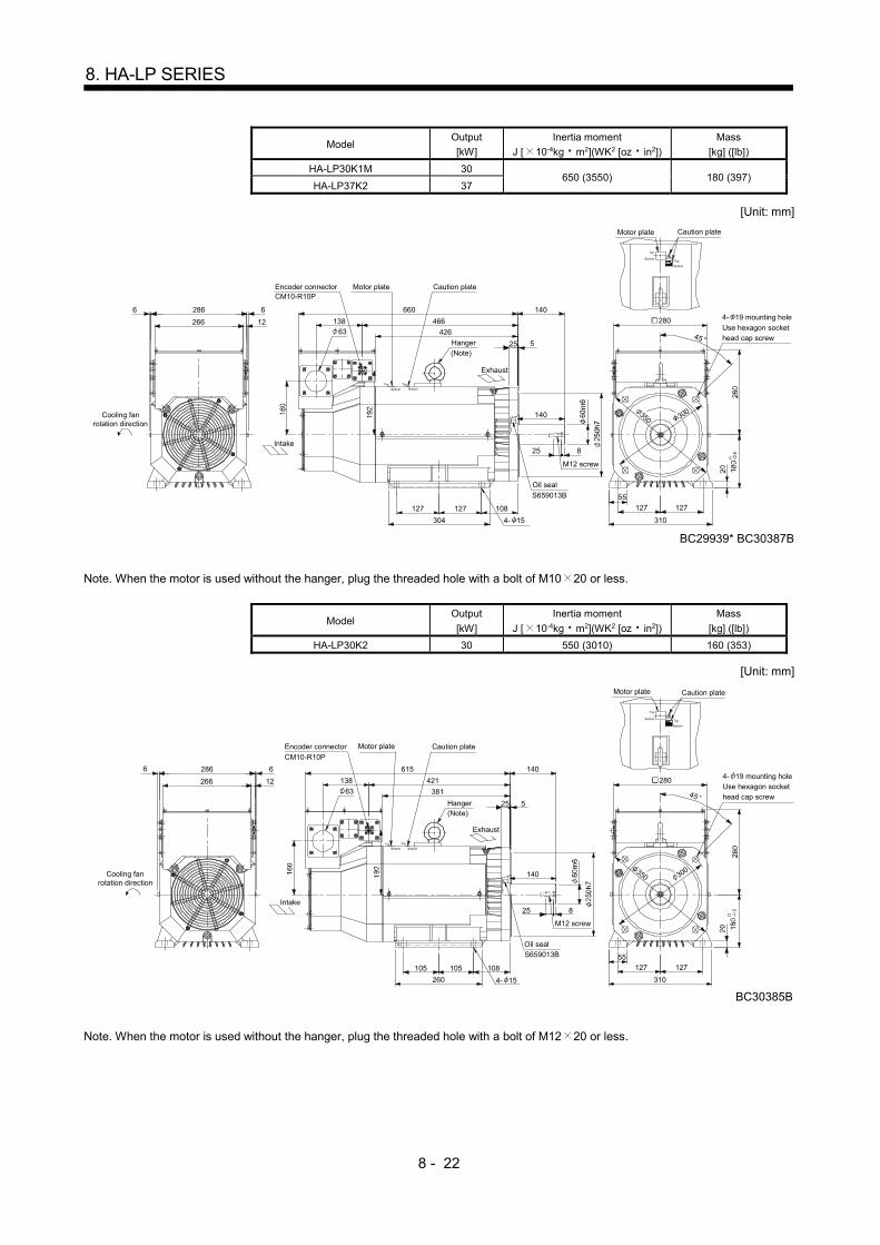
8 - 22
8. HA-LP SERIES
Model Output
[kW]
Inertia moment
J [ 10-4kg m2](WK2 [oz in2])
Mass
[kg] ([lb])
HA-LP30K1M 30 650 (3550) 180 (397)
HA-LP37K2 37
[Unit: mm]
140
14066
127
304
108127
25 8
12266
286 660
426
466138
25 5
310
127
BC29939* BC30387B
127
55
350 300
M12 screw
S659013B
CM10-R10P
Cooling fanrotation direction
Intake
Encoder connector
Motor plate Caution plate
Hanger(Note)
Exhaust
Oil seal
4- 19 mounting hole
Use hexagon sockethead cap screw
Motor plate Caution plate
Top Top
Bottom Bottom
Top
Top
Bottom
Bottom
280
45
4- 15
63
Note. When the motor is used without the hanger, plug the threaded hole with a bolt of M10 20 or less.
Model Output
[kW]
Inertia moment
J [ 10-4kg m2](WK2 [oz in2])
Mass
[kg] ([lb])
HA-LP30K2 30 550 (3010) 160 (353)
[Unit: mm]
140
14066
105
260
108105
25 8
12266
286 615
381
421138
25 5
310
127
BC30385B
12755
350 300
M12 screw
S659013B
CM10-R10P
Cooling fanrotation direction
Intake
Encoder connector
Motor plate Caution plate
Hanger(Note)
Exhaust
Oil seal
4- 19 mounting holeUse hexagon sockethead cap screw
Motor plate Caution plate
Top Top
Bottom Bottom
Top
Top
Bottom
Bottom
280
45
4- 15
63
Note. When the motor is used without the hanger, plug the threaded hole with a bolt of M12 20 or less.

8 - 23
8. HA-LP SERIES
8.7.3 With an electromagnetic brake
Model Output
[kW]
Brake static friction torque
[N m] ([oz in])
Inertia moment
J [ 10-4kg m2](WK2 [oz in2])
Mass
[kg] ([lb])
HA-LP601B HA-LP6014B 6
82 (11600) 113 (618) 70 (154) HA-LP701MB HA-LP701M4B 7
HA-LP11K2B HA-LP11K24B 11
[Unit: mm]
20
334
498
550
12
2066
146
6CM10-R10P
200
45
215
85
250
S45629B
80
3
5.219.8
M8 screw
93
Brake connectorMS3102A10SL-4P
55
Screw hole for eyebolt (M10)
Depth 20
Brake
Brake connector layout
Motor flange direction
301
Hanger(Note)
Oil seal
4- 14.5 mounting holeUse hexagon socket
head cap screw
Motor plate Caution plate
Top
BottomTop
Bottom
BC29965*
BA
Cooling fanrotation direction
Intake
Encoder connector
Motor plate
Caution plate
Exhaust
Top Bottom TopBottom
Note. When the motor is used without the hanger, plug the threaded hole with a bolt of M10 20 or less.
Model Output
[kW]
Brake static friction torque
[N m] ([oz in])
Inertia moment
J [ 10-4kg m2](WK2 [oz in2])
Mass
[kg] ([lb])
HA-LP801B HA-LP8014B 8
160.5 (22700) 293 (1600) 130 (287) HA-LP11K1MB HA-LP11K1M4B 11
HA-LP15K2B HA-LP15K24B 15
[Unit: mm]
BC29804B BC29807A BC29820B BC29861B
5
20.4 6.6
110
100
111.5
61012
250
180
6
397
6
560
25
376
BA
300
265
M10 screw
S60829B
CM10-R10P
Cooling fanrotation direction
Intake
Encoder connector
Motor plate
Hanger(Note)
Hanger
(Note)
Exhaust
Oil seal
4- 14.5 mounting hole
Use hexagon socket
head cap screw
Motor plate Caution plate
Top TopBottom Bottom
Top
Top
TopBottomBottom
Bottom
. .TUV plate, Caution plate
. .TUV plate
250
45
Brake
Motor flange directionBrake connector layout
MS3102A10SL-4P
Depth 22
Brake connector
Screw hole for eyebolt (M12)
Depth 22
Screw hole for eyebolt (M12)
Note. When the motor is used without the hanger, plug the threaded hole with a bolt of M12 20 or less.

8 - 24
8. HA-LP SERIES
Model Output
[kW]
Brake static friction torque
[N m] ([oz in])
Inertia moment
J [ 10-4kg m2](WK2 [oz in2])
Mass
[kg] ([lb])
HA-LP12K1B HA-LP12K14B 12
160.5 (22700) 369 (2020) 150 (331) HA-LP15K1MB HA-LP15K1M4B 15
HA-LP22K2B HA-LP22K24B 22
[Unit: mm]
BC29805B BC29808A BC29821B BC29822B BC29824B BC29825A
376
620
6
457
6
180
250
12670
111.5
110
100
525
BA
6.620.4
300
265
M10 screw
S60829B
CM10-R10P
Cooling fanrotation direction
Intake
Encoder connector
Motor plate
Hanger(Note)
Hanger
(Note)
Exhaust
Oil seal
4- 14.5 mounting hole
Use hexagon sockethead cap screw
Motor plate Caution plate
Top Top
Bottom Bottom
Top
Top
TopBottom Bottom
Bottom
. .TUV plate, Caution plate
. .TUV plate
250
45
Brake
Motor flange directionBrake connector layout
MS3102A10SL-4P
Depth 22
Brake connector
Screw hole for eyebolt (M12)
Depth 22
Screw hole for eyebolt (M12)
Note. When the motor is used without the hanger, plug the threaded hole with a bolt of M12 20 or less.
8.8 Servo motor with oil seal
For the servo motor with oil seal, the oil seal prevents the entry of oil into the servo motor. Install the servo motor horizontally, and set the oil level in the gear box to be lower than the oil seal lip always.
GearShaft
Servo motor
Oil seal
Height above oil level h
Lip
Servo motor Height above oil level h [mm]
HA-LP502 702 601(4)
HA-LP701M(4) 11K2(4) 34
HA-LP15K1(4) 20K1(4)
HA-LP22K1M(4)
30K1M(4)
HA-LP30K2(4) 37K2(4)
45
HA-LP801(4) 12K1(4)
25K1(4) 30K1(4)
HA-LP11K1M(4) 15K1M(4) 37K1M(4) 45K1M4
HA-LP15K2(4)
22K2(4) 45K24 55K24
48
HA-LP37K1(4) 50K1M4 55
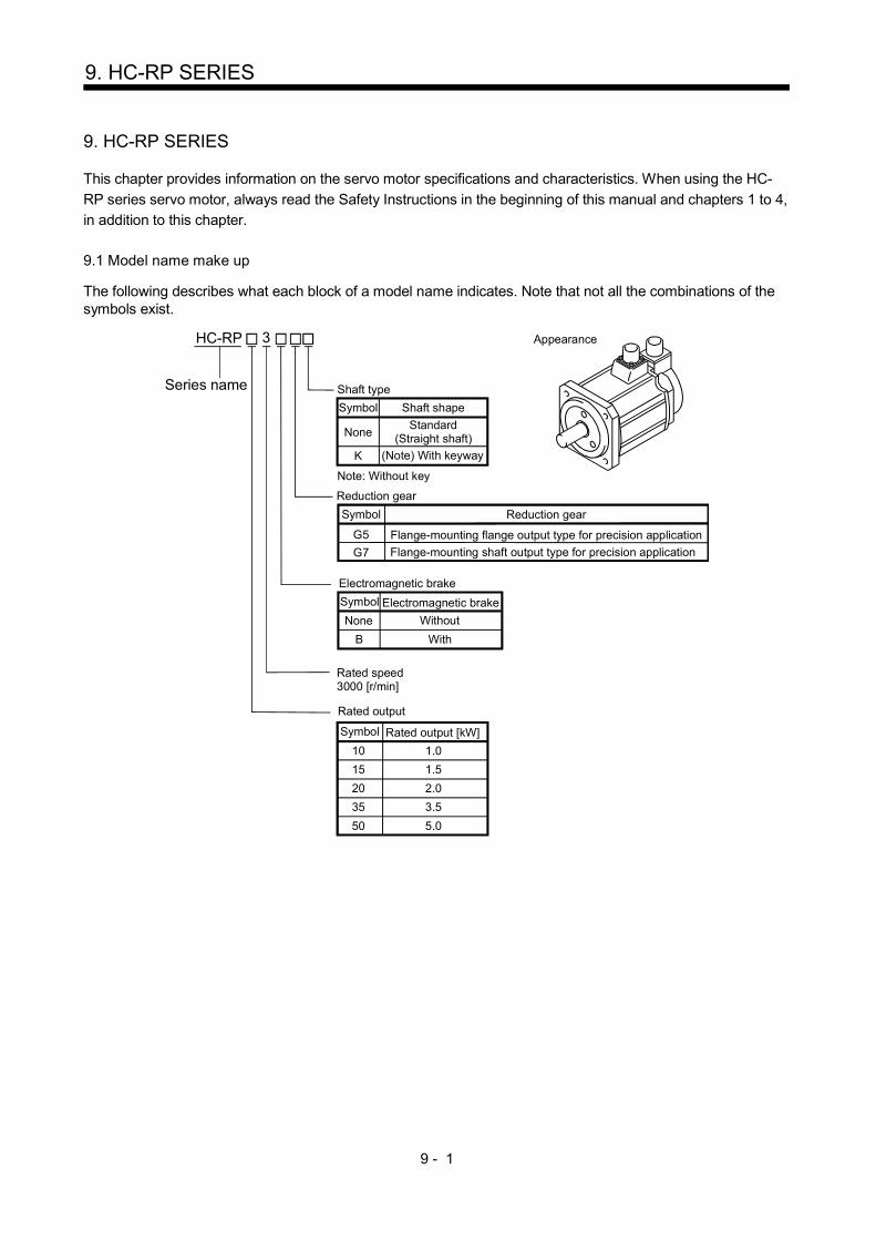
9 - 1
9. HC-RP SERIES
9. HC-RP SERIES
This chapter provides information on the servo motor specifications and characteristics. When using the HC-
RP series servo motor, always read the Safety Instructions in the beginning of this manual and chapters 1 to 4,
in addition to this chapter.
9.1 Model name make up
The following describes what each block of a model name indicates. Note that not all the combinations of the symbols exist.
HC-RP
Note: Without key
Shaft type
Symbol Shaft shape
NoneStandard
(Straight shaft)
K (Note) With keyway
Appearance
Without
Electromagnetic brake
Symbol Electromagnetic brake
B With
Rated speed3000 [r/min]
Rated output
3
Series name
None
10 1.0
15 1.5
20 2.0
35 3.5
50 5.0
Symbol Rated output [kW]
Symbol
Reduction gear
Flange-mounting flange output type for precision application
Flange-mounting shaft output type for precision application
Reduction gear
G5
G7

9 - 2
9. HC-RP SERIES
9.2 Standard specifications
9.2.1 Standard specifications list
Servo motor
Item
HC-RP series (Low inertia middle capacity)
103 153 203 353 503
Applicable servo
amplifier/drive unit
MR-J3- A/B/B-
RJ006/T 200 200 350 500 500
Continuous running
duty (Note 1)
Rated
output [kW] 1.0 1.5 2.0 3.5 5.0
Rated
torque
[N m] 3.18 4.78 6.37 11.1 15.9
[oz in] 450 677 902 1570 2250
Rated speed (Note 1) [r/min] 3000
Maximum speed [r/min] 4500
Instantaneous permissible speed [r/min] 5175
Maximum torque [N m] 7.95 11.9 15.9 27.9 39.7
[oz in] 1130 1690 2250 3950 5620
Power rate at continuous rated
torque [kW/s] 67.4 120 176 150 211
Inertia moment
(Note 3)
J [ 10-4kg m2] 1.5 1.9 2.3 8.3 12.0
WK2 [oz in2] 8.2 10.4 12.6 45.4 65.6
Recommended ratio of load inertia moment to
servo motor shaft inertia moment (Note 2) 5 times or less
Power supply capacity Refer to "Power supply equipment capacity and generated loss of servo
amplifiers" in Servo Amplifier Instruction Manual.
Rated current [A] 6.1 8.8 14 23 28
Maximum current [A] 18 23 37 58 70
Speed/position detector Encoder common to absolute position and incremental detection systems
(Resolution per servo motor 1 rotation: 262144 pulse/rev)
Accessory Oil seal
Insulation class 155(F)
Structure Totally-enclosed, natural-cooling (IP rating: IP65 (Note 4, 9))
Environmental
conditions
(Note 5)
Ambient
temperature
Operation [ ] 0 to 40 (non-freezing)
[ ] 32 to 104 (non-freezing)
Storage [ ] 15 to 70 (non-freezing)
[ ] 5 to 158 (non-freezing)
Ambient
humidity
Operation 10 to 80%RH (non-condensing)
Storage 10 to 90%RH (non-condensing)
Ambience Indoors (no direct sunlight)
Free from corrosive gas, flammable gas, oil mist, dust and dirt.
Altitude Max.1000m above sea level
Vibration resistance
(Note 6) [m/s2] X, Y: 24.5
Vibration rank (Note 7) V10
Permissible
load for the
shaft (Note 8)
L [mm] 45 63
Radial [N] 686 980
[lb] 154 220
Thrust [N] 196 392
[lb] 44.1 88.1
Mass (Note 3) [kg] 3.9 5.0 6.2 12 17
[lb] 8.6 11.0 13.7 26.5 37.5

9 - 3
9. HC-RP SERIES
Note 1. When the power supply voltage drops, we cannot guarantee the out put and rated speed.
2. If the load inertia moment ratio exceeds the indicated value, please contact your local sales office.
3. Refer to the outline dimension drawing for the servo motor with an electromagnetic brake.
4. Except for the shaft – through portion.
5. In the environment where the servo motor is exposed to oil mist, oil and/or water, the servo motor of the standard specifications
may not be usable. Contact your local sales office.
6. The vibration direction is as shown in the figure. The value is the one at the part that indicates the maximum value (normally the
opposite-to-load side bracket). When the servo motor stops, fretting is likely to occur at the bearing. Therefore, suppress the
vibration to about half of the permissible value.
YX
Servo motor
Vibration Vib
ratio
n am
plit
ude
(b
oth
amp
litud
es)
[ m
]
Speed [r/min]0 1000 2000 3000 4000 4500
10
100
1000
7. V10 indicates that the amplitude of a single servo motor is 10 m or less. The following figure shows the servo motor installation
position for measurement and the measuring position.
Servo motor
Top
Bottom
Measuring position
8. For the symbols in the table, refer to the following diagram: Do not subject the shaft to load greater than this value.
The values in the table assume that the loads work singly.
LRadial load
Thrust load
L: Distance from flange mounting surface to load center
9. When the servo motor is provided with the reduction gear, the IP rating of the reduction gear section is IP44.

9 - 4
9. HC-RP SERIES
9.2.2 Torque characteristics
POINT
For the system where the unbalanced torque occurs, such as a vertical axis system, the unbalanced torque of the machine should be kept at 70% or less of the rated torque.
When the power input of the servo amplifier is 3-phase 200VAC, the torque characteristic is indicated by the
thin line.
[HC-RP103]
1000 2000 3000 4000450000
3
6
9
Speed [r/min]
Continuousrunning range
Short-durationrunning range
Tor
que
[N•m
]
[HC-RP153]
Speed [r/min]
Continuousrunning range
Short-durationrunning range
Tor
que
[N•m
]
1000 2000 3000 4000450000
5
10
15
[HC-RP203]
1000 2000 3000 4000450000
6
12
18
Speed [r/min]
Continuousrunning range
Short-durationrunning range
Tor
que
[N•m
]
[HC-RP353]
1000 2000 3000 4000450000
10
20
30
Speed [r/min]
Continuousrunning range
Short-durationrunning range
Tor
que
[N•m
]
[HC-RP503]
1000 2000 3000 4000450000
15
30
45
Speed [r/min]
Continuousrunning range
Short-durationrunning range
Tor
que
[N•m
]

9 - 5
9. HC-RP SERIES
9.3 Electromagnetic brake
CAUTION
The electromagnetic brake is provided to prevent a drop at a power failure or alarm
occurrence during vertical drive or to hold a shaft at a stop. Do not use it for normal
braking (including braking at servo lock).
Before performing the operation, be sure to confirm that the electromagnetic brake
operates properly.
The operation time of the electromagnetic brake differs depending on the power
supply circuit you use. Be sure to check the operation delay time with a real
machine.
The characteristics of the electromagnetic brake provided for the servo motor with an electromagnetic brake
are indicated below.
Servo motor HC-RP series
Item 103B to 203B 353B 503B
Type (Note 1) Spring-loaded safety brake
Rated voltage (Note 4) 24V 010% DC
Capacity [W] at20 (68 ) 19 23
Coil resistance (Note 6) [ ] 30.0 25
Inductance (Note 6) [H] 0.81 0.70
Brake static friction torque [N m] 7 17
[oz in] 991 2410
Release delay time (Note 2) [s] 0.03 0.04
Braking delay
time (Note 2) [s] DC off 0.03 0.03
Permissible braking
work
Per braking [J] 400 400
Per hour [J] 4000 4000
Brake looseness at servo motor shaft (Note 5) [degrees] 0.2 to 0.6 0.2 to 0.6
Brake life (Note 3) Number of braking cycles [times] 20000 20000
Work per braking [J] 200 200
Selection example of
surge absorbers to
be used (Note 7, 8)
For the suppressed voltage 125V TND20V-680KB
For the suppressed voltage 350V TND10V-221KB
Note 1. There is no manual release mechanism. When it is necessary to hand-turn the servo motor shaft for machine centering, etc.,
use a separate 24VDC power supply to release the brake electrically.
2. The value for initial ON gap at 20 (68 ).
3. The brake gap will increase as the brake lining wears, but the gap is not adjustable. The brake life indicated is the number of
braking cycles after which adjustment will be required.
4. Always prepare a power supply exclusively used for the electromagnetic brake.
5. The above values are typical initial values and not guaranteed values.
6. These values are measured values and not guaranteed values.
7. Select the electromagnetic brake control relay properly, considering the characteristics of the electromagnetic brake and surge
absorber. When a diode is used as a surge absorber, it will take longer to activate the electromagnetic brake.
8. Manufactured by Nippon Chemi-Con Corporation.

9 - 6
9. HC-RP SERIES
9.4 Servo motors with special shafts
The servo motors with special shafts indicated by the symbol (K) in the table is available. K is the symbols
attached to the servo motor model names.
Servo motor Shaft shape
Keyway shaft (without key)
HC-RP K
Servo motor Variable dimensions
S R Q W QK QL U r
HC-RP103(B)K to
203(B)K 24h6 45 40 80
0.036 25 5 4 0.20 4
HC-RP353(B)K to
503(B)K 28h6 63 58 80
0.036 53 3 4 0.20 4
QK
A
Q
R
A
QL UW
r
M8Depth20
S
Section A-A
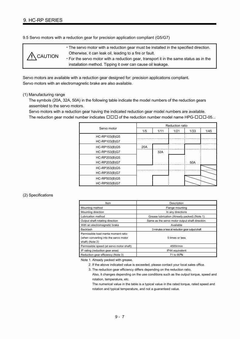
9 - 7
9. HC-RP SERIES
9.5 Servo motors with a reduction gear for precision application compliant (G5/G7)
CAUTION
The servo motor with a reduction gear must be installed in the specified direction.
Otherwise, it can leak oil, leading to a fire or fault.
For the servo motor with a reduction gear, transport it in the same status as in the
installation method. Tipping it over can cause oil leakage.
Servo motors are available with a reduction gear designed for: precision applications compliant.
Servo motors with an electromagnetic brake are also available.
(1) Manufacturing range
The symbols (20A, 32A, 50A) in the following table indicate the model numbers of the reduction gears
assembled to the servo motors.
Servo motors with a reduction gear having the indicated reduction gear model numbers are available.
The reduction gear model number indicates of the reduction number model name HPG- -05...
Servo motor Reduction ratio
1/5 1/11 1/21 1/33 1/45
HC-RP103(B)G5
HC-RP103(B)G7
HC-RP153(B)G5
HC-RP153(B)G7
20A
32A
HC-RP203(B)G5
HC-RP203(B)G7
50A
HC-RP353(B)G5
HC-RP353(B)G7
HC-RP503(B)G5
HC-RP503(B)G7
(2) Specifications
Item Description
Mounting method Flange mounting
Mounting direction In any directions
Lubrication method Grease lubrication (Already packed) (Note 1)
Output shaft rotating direction Same as the servo motor output shaft direction.
With an electromagnetic brake Available
Backlash 3 minutes or less at reduction gear output shaft
Permissible load inertia moment ratio
(when converting into the servo motor
shaft) (Note 2)
5 times or less
Permissible speed (at servo motor shaft) 4500r/min
IP rating (reduction gear area) IP44 equivalent
Reduction gear efficiency (Note 3) 71 to 90
Note 1. Already packed with grease.
2. If the above indicated value is exceeded, please contact your local sales office.
3. The reduction gear efficiency differs depending on the reduction ratio.
Also, it changes depending on the use conditions such as the output torque, speed and
rotation, temperature, etc.
The numerical value in the table is a typical value in the rated torque, rated speed and
rotation and typical temperature, and not a guaranteed value.
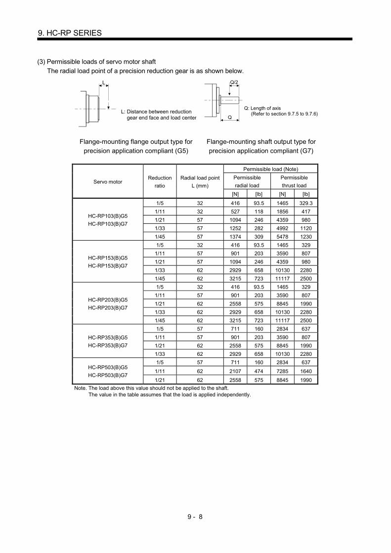
9 - 8
9. HC-RP SERIES
(3) Permissible loads of servo motor shaft
The radial load point of a precision reduction gear is as shown below.
L
L: Distance between reduction gear end face and load center
Q/2
Q
Q: Length of axis (Refer to section 9.7.5 to 9.7.6)
Flange-mounting flange output type for
precision application compliant (G5)
Flange-mounting shaft output type for
precision application compliant (G7)
Servo motor Reduction
ratio
Radial load point
L (mm)
Permissible load (Note)
Permissible
radial load
Permissible
thrust load
[N] [lb] [N] [lb]
HC-RP103(B)G5
HC-RP103(B)G7
1/5 32 416 93.5 1465 329.3
1/11 32 527 118 1856 417
1/21 57 1094 246 4359 980
1/33 57 1252 282 4992 1120
1/45 57 1374 309 5478 1230
HC-RP153(B)G5
HC-RP153(B)G7
1/5 32 416 93.5 1465 329
1/11 57 901 203 3590 807
1/21 57 1094 246 4359 980
1/33 62 2929 658 10130 2280
1/45 62 3215 723 11117 2500
HC-RP203(B)G5
HC-RP203(B)G7
1/5 32 416 93.5 1465 329
1/11 57 901 203 3590 807
1/21 62 2558 575 8845 1990
1/33 62 2929 658 10130 2280
1/45 62 3215 723 11117 2500
HC-RP353(B)G5
HC-RP353(B)G7
1/5 57 711 160 2834 637
1/11 57 901 203 3590 807
1/21 62 2558 575 8845 1990
1/33 62 2929 658 10130 2280
HC-RP503(B)G5
HC-RP503(B)G7
1/5 57 711 160 2834 637
1/11 62 2107 474 7285 1640
1/21 62 2558 575 8845 1990
Note. The load above this value should not be applied to the shaft. The value in the table assumes that the load is applied independently.
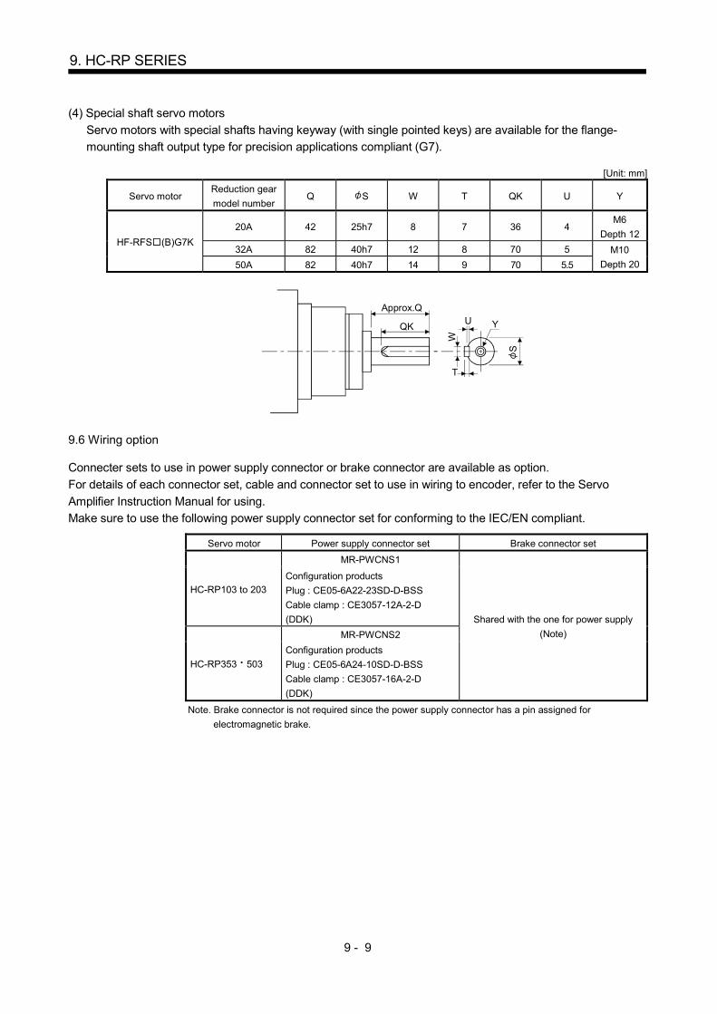
9 - 9
9. HC-RP SERIES
(4) Special shaft servo motors
Servo motors with special shafts having keyway (with single pointed keys) are available for the flange-
mounting shaft output type for precision applications compliant (G7).
[Unit: mm]
Servo motor Reduction gear
model number Q S W T QK U Y
HF-RFS (B)G7K
20A 42 25h7 8 7 36 4 M6
Depth 12
32A 82 40h7 12 8 70 5 M10
Depth 20 50A 82 40h7 14 9 70 5.5
UApprox.Q
QK
W
T
S
Y
9.6 Wiring option
Connecter sets to use in power supply connector or brake connector are available as option.
For details of each connector set, cable and connector set to use in wiring to encoder, refer to the Servo
Amplifier Instruction Manual for using.
Make sure to use the following power supply connector set for conforming to the IEC/EN compliant.
Servo motor Power supply connector set Brake connector set
HC-RP103 to 203
MR-PWCNS1
Shared with the one for power supply
(Note)
Configuration products
Plug : CE05-6A22-23SD-D-BSS
Cable clamp : CE3057-12A-2-D
(DDK)
HC-RP353 503
MR-PWCNS2
Configuration products
Plug : CE05-6A24-10SD-D-BSS
Cable clamp : CE3057-16A-2-D
(DDK)
Note. Brake connector is not required since the power supply connector has a pin assigned for
electromagnetic brake.
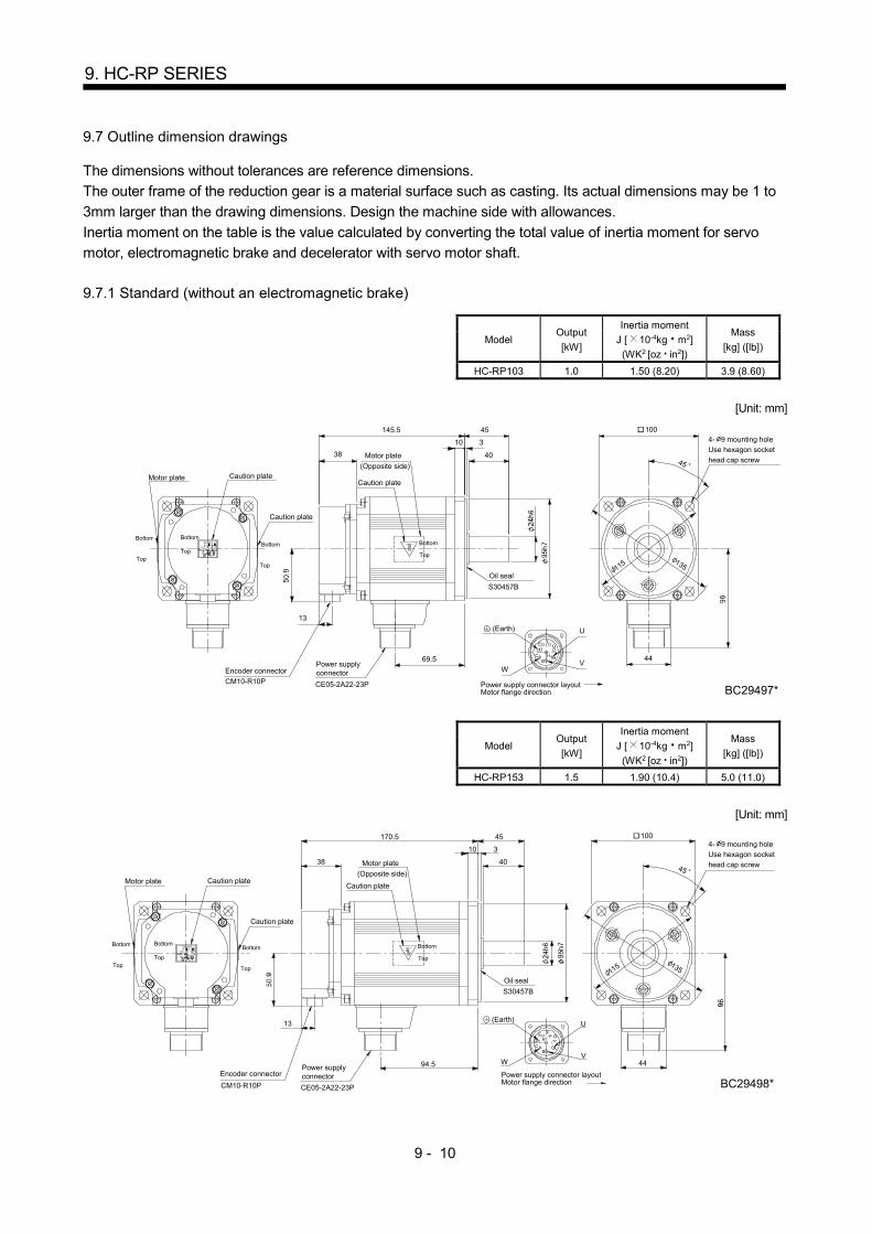
9 - 10
9. HC-RP SERIES
9.7 Outline dimension drawings
The dimensions without tolerances are reference dimensions.
The outer frame of the reduction gear is a material surface such as casting. Its actual dimensions may be 1 to
3mm larger than the drawing dimensions. Design the machine side with allowances.
Inertia moment on the table is the value calculated by converting the total value of inertia moment for servo
motor, electromagnetic brake and decelerator with servo motor shaft.
9.7.1 Standard (without an electromagnetic brake)
Model Output
[kW]
Inertia moment
J [ 10-4kg m2]
(WK2 [oz in2])
Mass
[kg] ([lb])
HC-RP103 1.0 1.50 (8.20) 3.9 (8.60)
[Unit: mm]
F
A
E
C
D
HB
G
38
145.5 45
40
310
100
4469.5
13
CE05-2A22-23P
S30457B
U
VW
BC29497*
4- 9 mounting holeUse hexagon socket
head cap screw
(Earth)
Oil seal
CM10-R10P
Encoder connectorPower supplyconnector
Motor plate Caution plateCaution plate
Caution plate
Motor plate
(Opposite side)45
115
Motor flange directionPower supply connector layout
Top
Bottom Bottom
TopBottom
Top
Bottom
Top 135
Model Output
[kW]
Inertia moment
J [ 10-4kg m2]
(WK2 [oz in2])
Mass
[kg] ([lb])
HC-RP153 1.5 1.90 (10.4) 5.0 (11.0)
[Unit: mm]
38
170.5 45
40
310
4494.5
13
CM10-R10P
WV
U
G
B
HDC
E
A
F
BC29498*
(Earth)
CE05-2A22-23P
S30457B
4- 9 mounting holeUse hexagon sockethead cap screw
Oil seal
Encoder connector
Motor plate Caution plateCaution plate
Caution plate
Motor plate
(Opposite side)
100
45
115
Motor flange directionPower supply connector layout
Top
Bottom Bottom
Top
Bottom
Top
Bottom
Top 135
Power supplyconnector
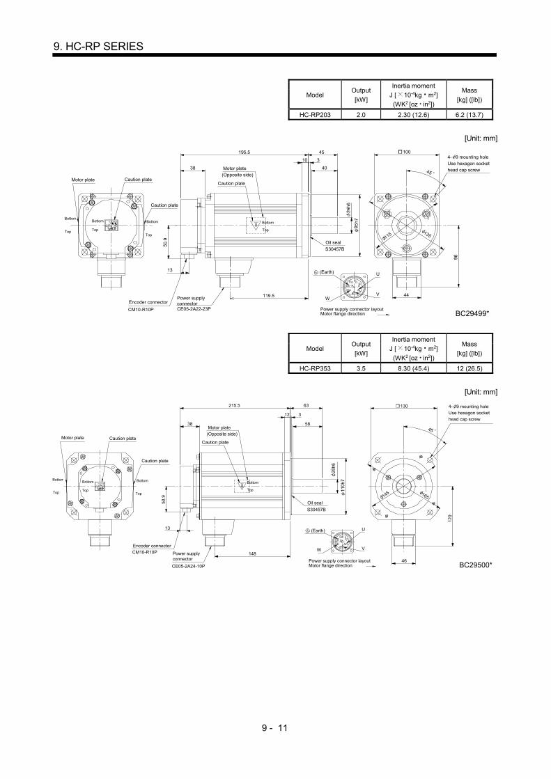
9 - 11
9. HC-RP SERIES
Model Output
[kW]
Inertia moment
J [ 10-4kg m2]
(WK2 [oz in2])
Mass
[kg] ([lb])
HC-RP203 2.0 2.30 (12.6) 6.2 (13.7)
[Unit: mm]
38
195.5 45
40
310
44119.5
13
WV
U
G
B
HD
C
E
A
F
BC29499*CM10-R10P CE05-2A22-23P
S30457B
4- 9 mounting holeUse hexagon sockethead cap screw
Oil seal
Encoder connector
Motor plate Caution plateCaution plate
Caution plate
Motor plate(Opposite side)
100
45
115
Motor flange directionPower supply connector layout
Top
BottomBottom
Top
Bottom
Top
Bottom
Top 135
Power supplyconnector
(Earth)
Model Output
[kW]
Inertia moment
J [ 10-4kg m2]
(WK2 [oz in2])
Mass
[kg] ([lb])
HC-RP353 3.5 8.30 (45.4) 12 (26.5)
[Unit: mm]
58
63
148
215.5
46
13
38
12 3
U
VW
BC29500*
A
ED
FG
BC
CM10-R10P
CE05-2A24-10P
S30457B
4- 9 mounting hole
Use hexagon socket
head cap screw
Oil seal
Encoder connector
Motor plate Caution plateCaution plate
Caution plate
Motor plate
(Opposite side)
130
45
145
Motor flange directionPower supply connector layout
Top
BottomBottom
Top
Bottom
Top
Bottom
Top 165
Power supplyconnector
(Earth)
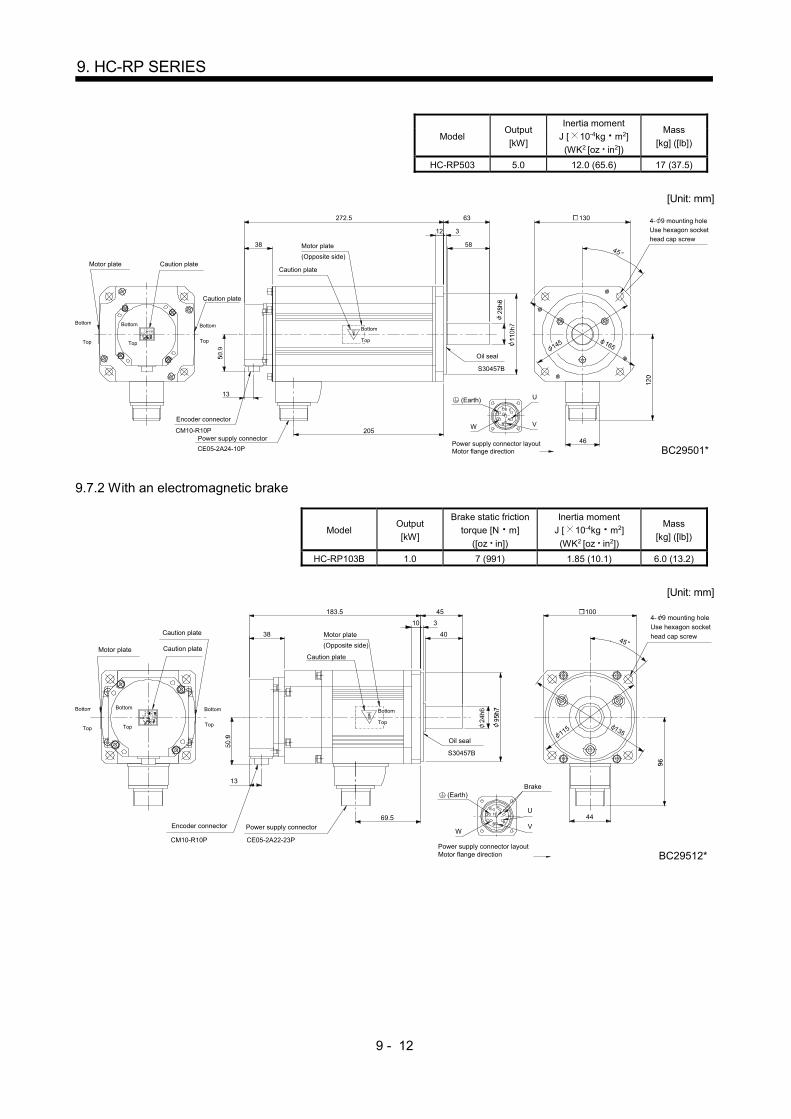
9 - 12
9. HC-RP SERIES
Model Output
[kW]
Inertia moment
J [ 10-4kg m2]
(WK2 [oz in2])
Mass
[kg] ([lb])
HC-RP503 5.0 12.0 (65.6) 17 (37.5)
[Unit: mm]
58
63
205
272.5
165 145
45
46
130
13
38
12 3
CE05-2A24-10P
S30457B
W V
U
BC29501*
CM10-R10P
CB
GF
DE
A
Bottom
Top
Power supply connector
Motor plate
(Opposite side)
Encoder connector
Caution plate
4- 9 mounting hole
Use hexagon socket
head cap screw
Power supply connector layoutMotor flange direction
Bottom
Top
Bottom
Top
Oil seal
Motor plate Caution plateCaution plate
Bottom
Top
(Earth)
9.7.2 With an electromagnetic brake
Model Output
[kW]
Brake static friction
torque [N m]
([oz in])
Inertia moment
J [ 10-4kg m2]
(WK2 [oz in2])
Mass
[kg] ([lb])
HC-RP103B 1.0 7 (991) 1.85 (10.1) 6.0 (13.2)
[Unit: mm]
38
183.5 45
40
310
100
44
45
69.5
13
CM10-R10P CE05-2A22-23P
115 135
S30457B
WV
UG
B
HD
C
E
A
F
BC29512*
Bottom
Top
Power supply connector
Motor plate
(Opposite side)
Encoder connector
4- 9 mounting holeUse hexagon socket
head cap screw
Brake
Power supply connector layoutMotor flange direction
Bottom
Top
Bottom
Top
Oil seal
Motor plate Caution plate
Caution plate
Caution plate
Bottom
Top
(Earth)
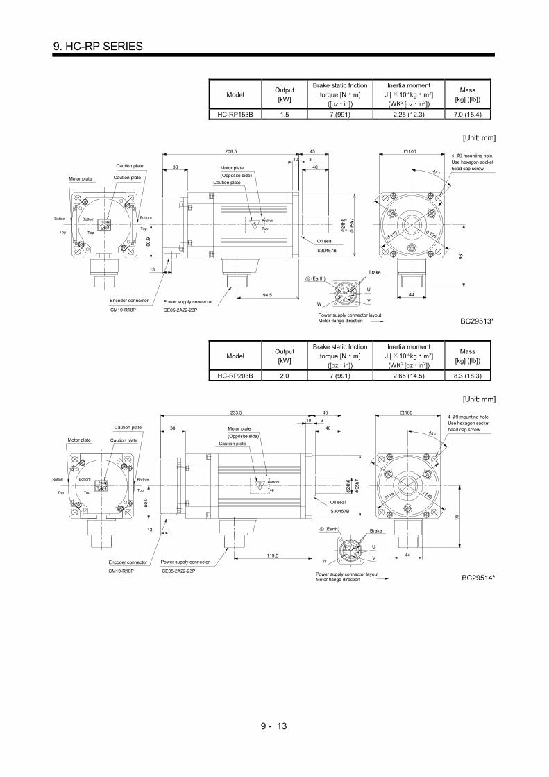
9 - 13
9. HC-RP SERIES
Model Output
[kW]
Brake static friction
torque [N m]
([oz in])
Inertia moment
J [ 10-4kg m2]
(WK2 [oz in2])
Mass
[kg] ([lb])
HC-RP153B 1.5 7 (991) 2.25 (12.3) 7.0 (15.4)
[Unit: mm]
38
208.5 45
40
310
100
44
45
94.5
13
CM10-R10P CE05-2A22-23P
115
135
S30457B
F
A
E
C
D H
B
G U
VW
BC29513*
Bottom
Top
Power supply connector
Motor plate
(Opposite side)
Encoder connector
4- 9 mounting hole
Use hexagon sockethead cap screw
Brake
Power supply connector layoutMotor flange direction
Bottom
Top
Bottom
Top
Oil seal
Motor plate Caution plate
Caution plate
Caution plate
Bottom
Top
(Earth)
Model Output
[kW]
Brake static friction
torque [N m]
([oz in])
Inertia moment
J [ 10-4kg m2]
(WK2 [oz in2])
Mass
[kg] ([lb])
HC-RP203B 2.0 7 (991) 2.65 (14.5) 8.3 (18.3)
[Unit: mm]
38
233.5 45
40
310
100
44
45
119.5
13
CM10-R10P CE05-2A22-23P
115 135
S30457B
F
A
E
C
D H
B
G U
VW
BC29514*
(Earth)
Bottom
Top
Power supply connector
Motor plate
(Opposite side)
Encoder connector
Brake
Power supply connector layoutMotor flange direction
Bottom
Top
Bottom
Top
Oil seal
Motor plate Caution plate
Caution plate
Caution plate
4- 9 mounting holeUse hexagon socket
head cap screw
Bottom
Top
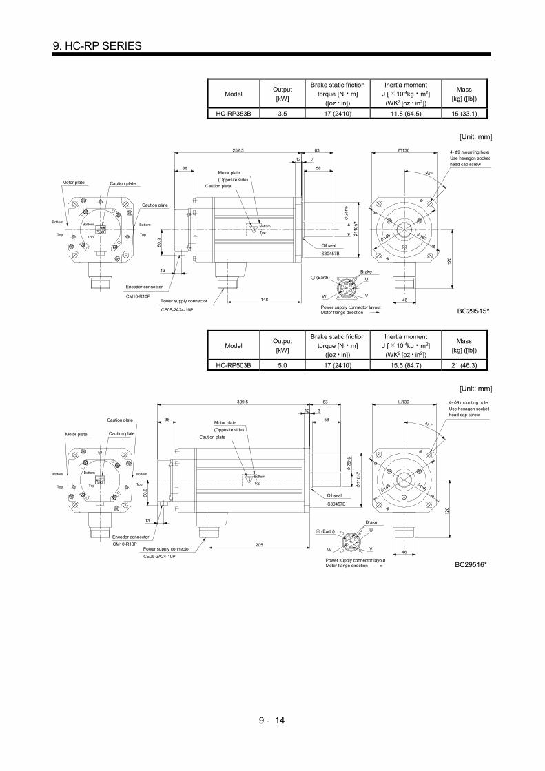
9 - 14
9. HC-RP SERIES
Model Output
[kW]
Brake static friction
torque [N m]
([oz in])
Inertia moment
J [ 10-4kg m2]
(WK2 [oz in2])
Mass
[kg] ([lb])
HC-RP353B 3.5 17 (2410) 11.8 (64.5) 15 (33.1)
[Unit: mm]
58
63
148
252.5
165 145
45
46
130
13
CM10-R10P
38
12 3
CE05-2A24-10P
S30457B
W V
U
BC29515*
Bottom
Top
Power supply connector
Motor plate
(Opposite side)
Encoder connector
4- 9 mounting hole
Use hexagon sockethead cap screw
Brake
Bottom
Top
Bottom
Top
Oil seal
Motor plate
Caution plate
Caution plateCaution plate
Power supply connector layoutMotor flange direction
(Earth)
CB
GF
D
E
A
Bottom
Top
Model Output
[kW]
Brake static friction
torque [N m]
([oz in])
Inertia moment
J [ 10-4kg m2]
(WK2 [oz in2])
Mass
[kg] ([lb])
HC-RP503B 5.0 17 (2410) 15.5 (84.7) 21 (46.3)
[Unit: mm]
58
63
205
309.5
165 145
45
46
130
13
CM10-R10P
38
12 3
CE05-2A24-10P
S30457B
U
VW
BC29516*
A
ED
FG
BC
Bottom
Top
Power supply connector
Motor plate
(Opposite side)
Encoder connector
4- 9 mounting hole
Use hexagon sockethead cap screw
Brake
Power supply connector layoutMotor flange direction
Bottom
Top
Bottom
Top
Oil seal
Motor plate
Caution plate
Caution plateCaution plate
Bottom
Top
(Earth)
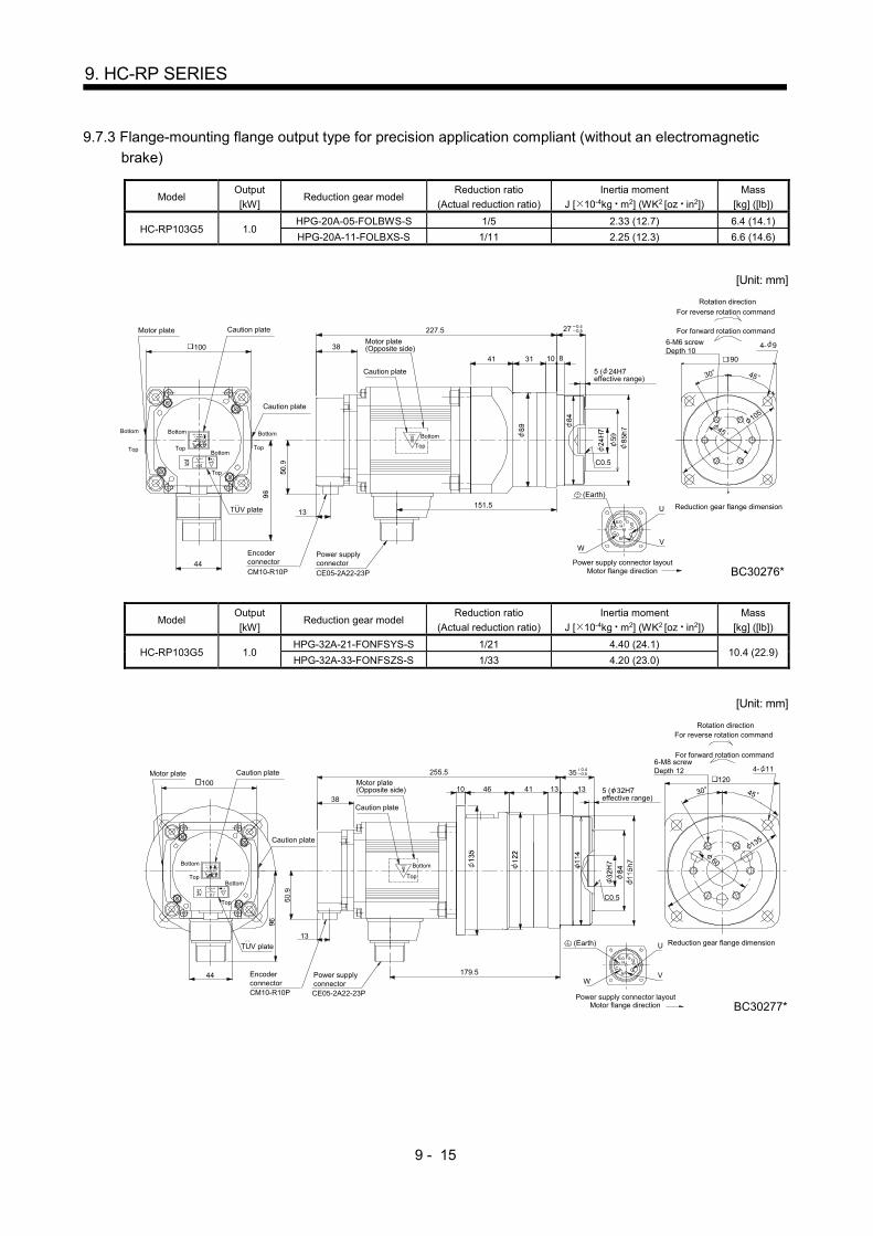
9 - 15
9. HC-RP SERIES
9.7.3 Flange-mounting flange output type for precision application compliant (without an electromagnetic
brake)
Model Output
[kW] Reduction gear model
Reduction ratio
(Actual reduction ratio)
Inertia moment
J [ 10-4kg m2] (WK2 [oz in2])
Mass
[kg] ([lb])
HC-RP103G5 1.0 HPG-20A-05-FOLBWS-S 1/5 2.33 (12.7) 6.4 (14.1)
HPG-20A-11-FOLBXS-S 1/11 2.25 (12.3) 6.6 (14.6)
[Unit: mm]
F
A
E
CD H
B
G
38
13 U
VW
C0.5
3141
45
90
30
4- 9
227.5
151.5
810
27 0.4 0.5
100
44
105
45
..
Encoderconnector
Power supplyconnector
Top
Motor plate(Opposite side)
Motor flange directionPower supply connector layout
Reduction gear flange dimension
5 ( 24H7effective range)
For reverse rotation command
For forward rotation command
Rotation direction
6-M6 screwDepth 10
CE05-2A22-23PCM10-R10P BC30276*
(Earth)
Motor plate
TUV plate
Caution plate
Caution plate
TopTop Top
Top
Bottom
Bottom
Caution plate
BottomBottom Bottom
Model Output
[kW] Reduction gear model
Reduction ratio
(Actual reduction ratio)
Inertia moment
J [ 10-4kg m2] (WK2 [oz in2])
Mass
[kg] ([lb])
HC-RP103G5 1.0 HPG-32A-21-FONFSYS-S 1/21 4.40 (24.1)
10.4 (22.9) HPG-32A-33-FONFSZS-S 1/33 4.20 (23.0)
[Unit: mm]
F
A
E
CD H
B
G
38
255.5
179.5
13U
VW
46 41 30 45
120
4- 11
10
35
1313100
44
..
0.4 0.5
Encoderconnector
Power supplyconnector
Top
Motor plate(Opposite side)
6-M8 screwDepth 12
5 ( 32H7effective range)
For reverse rotation command
For forward rotation command
Rotation direction
Motor flange directionPower supply connector layout
Reduction gear flange dimension
C0.5
CM10-R10P CE05-2A22-23P
BC30277*
(Earth)
60Bottom
Motor plate
TUV plate
Caution plate
Caution plate
Caution plate
Top
Top
Bottom
Bottom
135
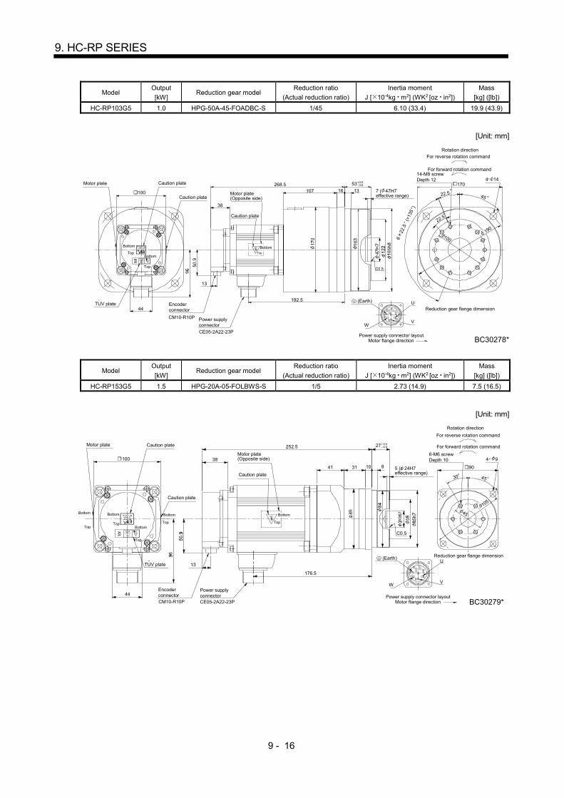
9 - 16
9. HC-RP SERIES
Model Output
[kW] Reduction gear model
Reduction ratio
(Actual reduction ratio)
Inertia moment
J [ 10-4kg m2] (WK2 [oz in2])
Mass
[kg] ([lb])
HC-RP103G5 1.0 HPG-50A-45-FOADBC-S 1/45 6.10 (33.4) 19.9 (43.9)
[Unit: mm]
F
A
E
CD H
B
G
38
13
U
VW
170
622
.5
(=13
5 )
100
22.5
4 14
BC30278*
22.5 45107
C0.5
268.5
192.5
53
1316 100
44
0.5 0.8
Motor plate(Opposite side)
Top
14-M8 screwDepth 12
7 ( 47H7effective range)
Motor flange directionPower supply connector layout
Reduction gear flange dimension
For reverse rotation command
For forward rotation command
Rotation direction
CE05-2A22-23P
CM10-R10P
190
(Earth)
Motor plate
Encoderconnector
TUV plate
Caution plate
Caution plate
Caution plate
Power supplyconnector
Top
Top
Bottom
Bottom
Bottom
Model Output
[kW] Reduction gear model
Reduction ratio
(Actual reduction ratio)
Inertia moment
J [ 10-4kg m2] (WK2 [oz in2])
Mass
[kg] ([lb])
HC-RP153G5 1.5 HPG-20A-05-FOLBWS-S 1/5 2.73 (14.9) 7.5 (16.5)
[Unit: mm]
38
13
WV
U
G
B
HDC
E
A
F
C0.5
41
45
90
30
4 9
252.5
176.5
10 8
27
31
44
100
45
0.40.5
6-M6 screwDepth 10
5 ( 24H7effective range)
Motor flange directionPower supply connector layout
Reduction gear flange dimension
For reverse rotation command
Rotation direction
For forward rotation command
BC30279*
105
(Earth)
Motor plate
TUV plate
Caution plate
Caution plate
Caution plate
TopTop
Top
Top
Bottom Bottom
Bottom
Bottom
EncoderconnectorCM10-R10P
Power supplyconnectorCE05-2A22-23P
Top
Motor plate(Opposite side)
Bottom

9 - 17
9. HC-RP SERIES
Model Output
[kW] Reduction gear model
Reduction ratio
(Actual reduction ratio)
Inertia moment
J [ 10-4kg m2] (WK2 [oz in2])
Mass
[kg] ([lb])
HC-RP153G5 1.5 HPG-32A-11-FONFSPS-S 1/11 5.20 (28.4)
11.5 (25.4) HPG-32A-21-FONFSYS-S 1/21 4.80 (26.2)
[Unit: mm]
38
13
WV
U
G
B
HDC
E
A
F
30 45
1204 11
46
C0.5
10
280.5
204.5
35
13 1341
44
60
0.4 0.5
Top
Motor plate(Opposite side)
6-M8 screwDepth 12
5 ( 32H7tolerance range)
Motor flange directionPower supply connector layout
Reduction gear flange dimension
For reverse rotation command
For forward rotation command
Rotation direction
CE05-2A22-23P BC30280*
135
(Earth)
Bottom
Motor plate
EncoderconnectorCM10-R10P
100
TUV plate
Caution plate Caution plate
Caution plate
Power supplyconnector
Top Top
Top
Top
Bottom
Bottom
BottomBottom
Model Output
[kW] Reduction gear model
Reduction ratio
(Actual reduction ratio)
Inertia moment
J [ 10-4kg m2] (WK2 [oz in2])
Mass
[kg] ([lb])
HC-RP153G5 1.5 HPG-50A-33-FOADBC-S 1/33 6.60 (36.1)
21.0 (46.3) HPG-50A-45-FOADBC-S 1/45 6.50 (35.5)
[Unit: mm]
38
13
WV
U
G
B
HDC
E
A
F
107 170
45
100
22.5
22.5
C0.5
4 14
6 2
2.5(
=135
)
293.5
16 13
217.5
53
44
Motor plate
100
TUV plate
Caution plate Caution plate
Caution plate
Top
Top
Top
Bottom Bottom
Bottom
Bottom
Top
EncoderconnectorCM10-R10P
Power supplyconnector
CE05-2A22-23P
Top
Motor plate(Opposite side)
14-M8 screwDepth
7 ( 47H7effective range)
Motor flange directionPower supply connector layout
Reduction gear flange dimension
BC30281*
For forward rotation command
Rotation direction
For reverse rotation command
190
(Earth)
Bottom
0.5 0.8
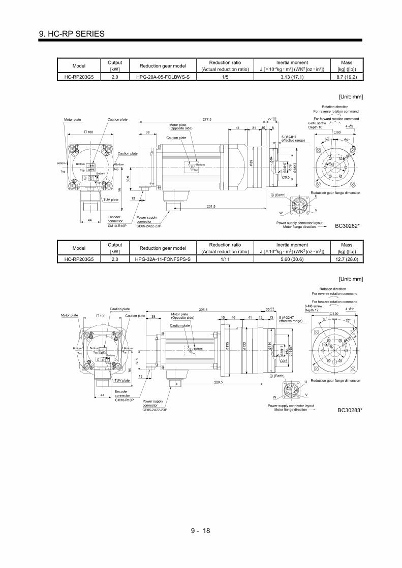
9 - 18
9. HC-RP SERIES
Model Output
[kW] Reduction gear model
Reduction ratio
(Actual reduction ratio)
Inertia moment
J [ 10-4kg m2] (WK2 [oz in2])
Mass
[kg] ([lb])
HC-RP203G5 2.0 HPG-20A-05-FOLBWS-S 1/5 3.13 (17.1) 8.7 (19.2)
[Unit: mm]
38
13
WV
U
G
B
HDC
E
A
F
45
90
30
4 93141 10 8
27
45
0.4 0.5Motor plate
Encoderconnector
100
TUV plate
Caution plate
Caution plate
Caution plate
Power supplyconnectorCE05-2A22-23P
Top Top Top
Top
Bottom Bottom Bottom
Bottom
CM10-R10P
6-M6 screwDepth 10
5 ( 24H7effective range)
Motor flange directionPower supply connector layout
Reduction gear flange dimension
For reverse rotation command
For forward rotation command
Rotation direction
BC30282*
C0.5
105
(Earth)
277.5
201.5
44
Top
Motor plate(Opposite side)
Bottom
Model Output
[kW] Reduction gear model
Reduction ratio
(Actual reduction ratio)
Inertia moment
J [ 10-4kg m2] (WK2 [oz in2])
Mass
[kg] ([lb])
HC-RP203G5 2.0 HPG-32A-11-FONFSPS-S 1/11 5.60 (30.6) 12.7 (28.0)
[Unit: mm]
38
13
V
G
B
HDC
E
A
F
46 4130 45
C0.5
120
4 11
10 13 13
35
135
60
0.4 0.5
Motor plate
EncoderconnectorCM10-R10P
100
TUV plate
Caution plate
Caution plate
Power supplyconnectorCE05-2A22-23P
Top Top
Top
Top
Bottom
Bottom
Caution plate
Top
Motor plate(Opposite side)
6-M8 screwDepth 12
5 ( 32H7effective range)
Motor flange directionPower supply connector layout
Reduction gear flange dimension
For reverse rotation command
For forward rotation command
Rotation direction
BC30283*
(Earth)
305.5
229.5
44
U
W
Bottom Bottom Bottom

9 - 19
9. HC-RP SERIES
Model Output
[kW] Reduction gear model
Reduction ratio
(Actual reduction ratio)
Inertia moment
J [ 10-4kg m2] (WK2 [oz in2])
Mass
[kg] ([lb])
HC-RP203G5
2.0
HPG-50A-21-FOADBC-S 1/21 8.00 (43.7)
22.2 (48.9) HPG-50A-33-FOADBC-S 1/33 7.00 (38.3)
HPG-50A-45-FOADBC-S 1/45 6.90 (37.7)
[Unit: mm]
38
13
WV
U
G
B
HDC
E
A
F
107 170
45
622
.5 (
=135
)
100
22.5
22.5
C0.5
4 14
BC30284*
16 13
53
44
0.5 0.8
14-M8 screwDepth 12
7 ( 47H7effective range)
Motor flange directionPower supply connector layout
Reduction gear flange dimension
For reverse rotation command
For forward rotation command
Rotation direction
190
(Earth)
Bottom
318.5
242.5
Caution plate
Top
Motor plate(Opposite side)
Motor plate
EncoderconnectorCM10-R10P
100
TUV plate
Caution plateCaution plate
Power supplyconnector
CE05-2A22-23P
Top Top
Top
Top
Bottom Bottom
Bottom
Bottom
Model Output
[kW] Reduction gear model
Reduction ratio
(Actual reduction ratio)
Inertia moment
J [ 10-4kg m2] (WK2 [oz in2])
Mass
[kg] ([lb])
HC-RP353G5 3.5 HPG-32A-05-FOPAQS-S 1/5 13.2 (72.2) 18.5 (40.8)
HPG-32A-11-FOPAR-S 1/11 13.0 (71.1) 19.0 (41.9)
[Unit: mm]
13
38
U
VW
9125
4530
C0.5
4 11
120
344.5
13 13
35
277
46
60
0.4 0.5
6-M8 screwDepth 12
5 ( 32H7effective range)
Motor flange directionPower supply connector layout
Reduction gear flange dimension
For reverse rotation command
For forward rotation command
Rotation direction
BC30285*
(Earth)
Bottom
A
ED
FG
BC
135
Motor plate
Encoderconnector
CM10-R10P
130
TUV plate
Caution plate
Caution plate
Caution plate
CE05-2A24-10P
Top Top
Top
Top
BottomBottom
Bottom
Bottom
Power supplyconnector
Top
Motor plate(Opposite side)

9 - 20
9. HC-RP SERIES
Model Output
[kW] Reduction gear model
Reduction ratio
(Actual reduction ratio)
Inertia moment
J [ 10-4kg m2] (WK2 [oz in2])
Mass
[kg] ([lb])
HC-RP353G5 3.5 HPG-50A-21-FOBADD-S 1/21 15.0 (82.0)
28.1 (62.0) HPG-50A-33-FOBADD-S 1/33 14.1 (77.1)
[Unit: mm]
13
38
U
VW
6325 45
622
.5 (
=135
)
190
170
22.5
22.5 45
C0.5
1
2
364.5 4 14
1316
53
12.5
46
297
0.50.8
BC30286*
CM10-R10P
A
ED
FG
BC
Motor plate
Encoderconnector
130
TUV plate
Caution plate
Caution plate
Caution plate
Power supplyconnector
14-M8 screwDepth 12
7 ( 47H7effective range)
CE05-2A24-10P
Top Top
Top
Top
Bottom
Bottom
Motor flange directionPower supply connector layout
Reduction gear flange dimension
For reverse rotation command
For forward rotation command
Rotation direction
Motor plate(Opposite side)
BottomTop
Bottom Bottom
100
(Earth)
Note. *1 and *2 are the screw holes (M8) for the hangers.
Model Output
[kW] Reduction gear model
Reduction ratio
(Actual reduction ratio)
Inertia moment
J [ 10-4kg m2] (WK2 [oz in2])
Mass
[kg] ([lb])
HC-RP503G5 5.0 HPG-32A-05-FOPAQS-S 1/5 16.9 (92.4) 23.5 (51.8)
[Unit: mm]
13
38
W V
U
9125
4530
60
135
4 11
120
401.5
13 13
35
334
46
0.4 0.5
Caution plate
6-M8 screwDepth 12
5 ( 32H7effective range)
Motor flange directionPower supply connector layout
Reduction gear flange dimension
For reverse rotation command
For forward rotation command
Rotation direction
C0.5
BC30287*
(Earth)
Bottom
CB
GF
DE
A
Motor plate
Encoderconnector
CM10-R10P
130
TUV plate
Caution plate
Caution plate
Power supplyconnector
CE05-2A24-10P
Top Top
Top
Top
Bottom Bottom
Bottom
Bottom
Top
Motor plate(Opposite side)

9 - 21
9. HC-RP SERIES
Model Output
[kW] Reduction gear model
Reduction ratio
(Actual reduction ratio)
Inertia moment
J [ 10-4kg m2] (WK2 [oz in2])
Mass
[kg] ([lb])
HC-RP503G5 5.0 HPG-50A-11-FOBADD-S 1/11 20.5 (112)
33.1 (73.0) HPG-50A-21-FOBADD-S 1/21 18.7 (102)
[Unit: mm]
13
38
W V
U
63
53 0.8 0.5
25 45
6 2
2.5
(=13
5 )
170
22.5 45
C0.5
12.5
1
2
4 14421.5
1316
354
46
190
CM10-R10P
22.5
Bottom
BC30288*
(Earth)
CB
GF
DE
A
Motor plate
Encoderconnector
130
TUV plate
Caution plate
Power supplyconnector
CE05-2A24-10P
Top Top
Top
Top
Bottom
Bottom
Bottom Bottom
Cautionplate
Caution plate
Motor plate(Opposite side)
14-M8screwDepth 12
7 ( 47H7effective range)
Reduction gear flange dimension
For reverse rotation command
For forward rotation command
Rotation direction
Motor flange directionPower supply connector layout
Top
Note. *1 and *2 are the screw holes (M8) for the hangers.
9.7.4 Flange-mounting flange output type for precision application compliant (with an electromagnetic brake)
Model Output [kW]
Reduction gear model Reduction ratio
(Actual reduction ratio)
Brake static friction torque
[N m] ([oz in])
Inertia moment J [ 10-4kg m2] (WK2 [oz in2])
Mass [kg] ([lb])
HC-RP103BG5 1.0 HPG-20A-05-FOLBWS-S 1/5
7.0 (991) 2.68 (14.7) 8.5 (18.7)
HPG-20A-11-FOLBXS-S 1/11 2.60 (14.2) 8.7 (19.2)
[Unit: mm]
38
50.9
13
CE05-2A22-23PCM10-R10P
W V
UG
B
HD
C
E
A
F
45
45
105
90
30
5
9
85h7
84
C0.5
4- 93141
89
BC30289*
265.5
8
27
10
24H
7
151.5
96
100
44
0.4 0.5
Reduction gear flange dimension
6-M6 screwDepth 10
For reverse rotation command
For forward rotation command
Rotation direction
..TUV plate
Motor plate
BottomBottom
Bottom
Caution plate
Caution plate
Bottom
TopTop
Top
Top
Encoderconnector
Power supplyconnector
Motor plate(Opposite side)
Caution plate5( 24H7effective range)
Motor flange directionPower supply connector layout
Bottom
Top
(Earth)
Brake
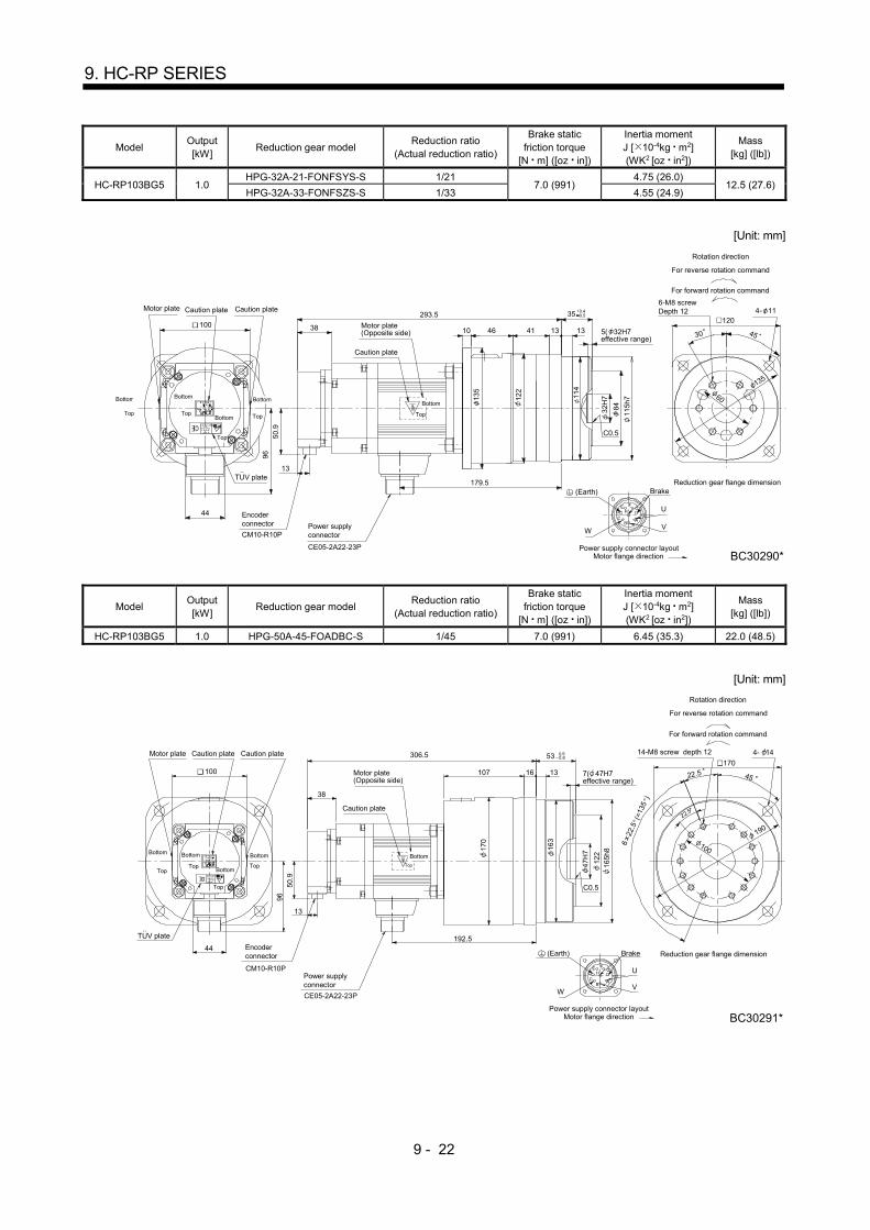
9 - 22
9. HC-RP SERIES
Model Output [kW]
Reduction gear model Reduction ratio
(Actual reduction ratio)
Brake static friction torque
[N m] ([oz in])
Inertia moment J [ 10-4kg m2] (WK2 [oz in2])
Mass [kg] ([lb])
HC-RP103BG5 1.0 HPG-32A-21-FONFSYS-S 1/21
7.0 (991) 4.75 (26.0)
12.5 (27.6) HPG-32A-33-FONFSZS-S 1/33 4.55 (24.9)
[Unit: mm]
38
50.9
13
W V
UG
B
HD
C
E
A
F
35
11
4
11
5h7
46 41
84
32H
7
C0.5
1204- 11
10
135
1
22
BC30290*
1313
179.5
293.5 100
96
44
135
60
0.5 0.4
30 45
Brake
Top
Bottom
CE05-2A22-23P
Power supplyconnector
Top
Bottom
Bottom
Top
6-M8 screwDepth 12
For reverse rotation command
For forward rotation command
Rotation direction
Reduction gear flange dimension
Motor flange directionPower supply connector layout
CM10-R10P
..TUV plate
Encoderconnector
Motor plate Caution plateCaution plate
Motor plate(Opposite side)
Caution plate
5( 32H7effective range)
Bottom
Top
Bottom
Top
(Earth)
Model Output [kW]
Reduction gear model Reduction ratio
(Actual reduction ratio)
Brake static friction torque
[N m] ([oz in])
Inertia moment J [ 10-4kg m2] (WK2 [oz in2])
Mass [kg] ([lb])
HC-RP103BG5 1.0 HPG-50A-45-FOADBC-S 1/45 7.0 (991) 6.45 (35.3) 22.0 (48.5)
[Unit: mm]
38
50.9
13
WV
UG
B
HDC
E
A
F
47
H7
1
22 1
63
1
65h8
107 45
6 2
2.5
(=13
5 )
22.5
22.5
17
0
4- 14
BC30291*
306.5
192.5
16 13
53
96
44
190
100
0.5 0.8
100
Bottom
Top
Bottom
TopBottom
Top
Bottom
Top
170
CE05-2A22-23P
Power supplyconnector
Bottom
Top
14-M8 screw depth 12
For reverse rotation command
For forward rotation command
Rotation direction
Reduction gear flange dimension
Motor flange directionPower supply connector layout
CM10-R10P
..TUV plate
Encoderconnector
Motor plate Caution plateCaution plate
Motor plate(Opposite side)
Caution plate
7( 47H7effective range)
C0.5
(Earth) Brake

9 - 23
9. HC-RP SERIES
Model Output [kW]
Reduction gear model Reduction ratio
(Actual reduction ratio)
Brake static friction torque
[N m] ([oz in])
Inertia moment J [ 10-4kg m2] (WK2 [oz in2])
Mass [kg] ([lb])
HC-RP153BG5 1.5 HPG-20A-05-FOLBWS-S 1/5 7.0 (991) 3.08 (16.8) 9.5 (20.9)
[Unit: mm]
45
38
50.9
13
F
A
E
CD H
B
G U
VW
5
9
8
5h7
84
C0.5
3141
89
290 27
810
2
4H
7
176.5
96
42
105
0.40.5
Bottom
Top
Bottom
Top
100 4- 9
90
4530
CE05-2A22-23P
Power supplyconnector
(Earth)Brake
BC30292*
6-M6 screwDepth 10
For reverse rotation command
For forward rotation command
Rotation direction
Reduction gear flange dimension
Motor flange directionPower supply connector layout
CM10-R10P
..TUV plate
Encoderconnector
Motor plate Caution plate
Caution plate
Motor plate(Opposite side)
Caution plate5( 24H7effective range)
Bottom
Top
Bottom
Top
Bottom
Top
Model Output [kW]
Reduction gear model Reduction ratio
(Actual reduction ratio)
Brake static friction torque
[N m] ([oz in])
Inertia moment J [ 10-4kg m2] (WK2 [oz in2])
Mass [kg] ([lb])
HC-RP153BG5 1.5 HPG-32A-11-FONFSPS-S 1/11
7.0 (991) 5.55 (30.3)
13.5 (29.8) HPG-32A-21-FONFSYS-S 1/21 5.15 (28.2)
[Unit: mm]
38
50.9
13
F
A
E
CD H
B
G U
VW
114
115h
7
46 41
84
32H
7
C0.5
10
13
5
122
318.5
204.5
1313
96
44
135
60
35 0.40.5 6-M8 screw depth 12 4- 11
1204530
Brake
100
Bottom
Top
Bottom
Top Bottom
Top
Top
Bottom
BC30293*
For reverse rotation command
For forward rotation command
Rotation direction
Reduction gear flange dimension
Motor flange directionPower supply connector layout
CM10-R10P
..TUV plate
Encoderconnector
Motor plate
Caution plate
Caution plate
Motor plate(Opposite side)
Caution plate
5( 32H7effective range)
CE05-2A22-23P
Power supplyconnector
Bottom
Top
(Earth)
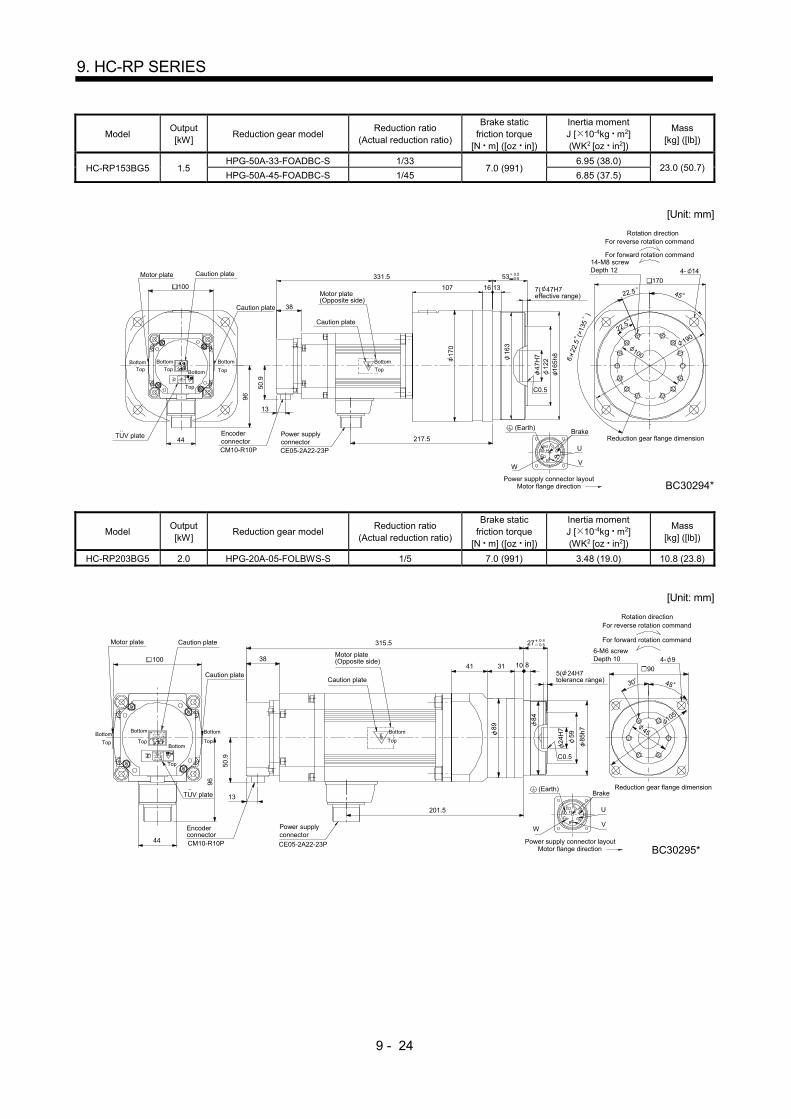
9 - 24
9. HC-RP SERIES
Model Output [kW]
Reduction gear model Reduction ratio
(Actual reduction ratio)
Brake static friction torque
[N m] ([oz in])
Inertia moment J [ 10-4kg m2] (WK2 [oz in2])
Mass [kg] ([lb])
HC-RP153BG5 1.5 HPG-50A-33-FOADBC-S 1/33
7.0 (991) 6.95 (38.0)
23.0 (50.7) HPG-50A-45-FOADBC-S 1/45 6.85 (37.5)
[Unit: mm]
13
38
50.9
13
CE05-2A22-23PF
A
E
CD H
B
G U
VW
47H
7
122
163
165h
8
107 170
190
45
100
22.5
22.5
C0.5
170
4- 14
6 2
2.5
(=1
35
)
331.5
217.5
16
53
100
96
44
0.5 0.8
BC30294*
TopBottom Bottom
Top
Top
TopBottom
Bottom
(Earth)Brake
Bottom
Top
Power supplyconnector
14-M8 screwDepth 12
For reverse rotation command
For forward rotation command
Rotation direction
Reduction gear flange dimension
Motor flange directionPower supply connector layout
CM10-R10P
Encoderconnector
Motor plate
Caution plate
Caution plate
Motor plate(Opposite side)
Caution plate
7( 47H7effective range)
TUV plate
Model Output [kW]
Reduction gear model Reduction ratio
(Actual reduction ratio)
Brake static friction torque
[N m] ([oz in])
Inertia moment J [ 10-4kg m2] (WK2 [oz in2])
Mass [kg] ([lb])
HC-RP203BG5 2.0 HPG-20A-05-FOLBWS-S 1/5 7.0 (991) 3.48 (19.0) 10.8 (23.8)
[Unit: mm]
27 0.4 0.5
38
50.9
13
CE05-2A22-23P
F
A
E
CD H
B
G U
VW
45
45
105
90
30
59
85h7
84
C0.5
4- 93141
89
315.5
201.5
2
4H7
810
96
44
100
BC30295*
(Earth)Brake
Bottom
Top
6-M6 screwDepth 10
For reverse rotation command
For forward rotation command
Rotation direction
Reduction gear flange dimension
Motor flange directionPower supply connector layoutCM10-R10P
Encoderconnector
Motor plate
Caution plate
Caution plate
Motor plate(Opposite side)
Caution plate5( 24H7tolerance range)
Power supplyconnector
Top
Bottom
Bottom
Bottom Bottom
Top
Top
Top
TUV plate
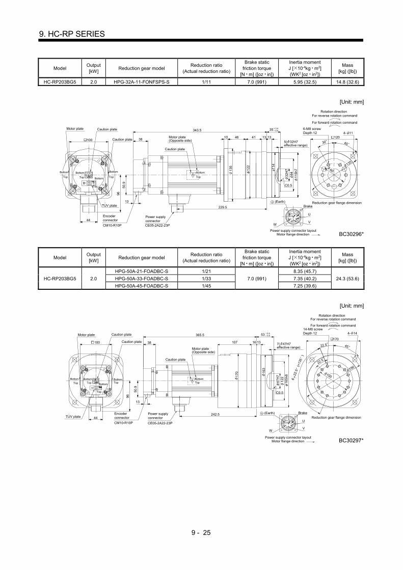
9 - 25
9. HC-RP SERIES
Model Output [kW]
Reduction gear model Reduction ratio
(Actual reduction ratio)
Brake static friction torque
[N m] ([oz in])
Inertia moment J [ 10-4kg m2] (WK2 [oz in2])
Mass [kg] ([lb])
HC-RP203BG5 2.0 HPG-32A-11-FONFSPS-S 1/11 7.0 (991) 5.95 (32.5) 14.8 (32.6)
[Unit: mm]
38
50.9
13
CE05-2A22-23P
F
A
E
C
D H
B
G U
VW
1
14
1
15h7
46 41
30 45
8
4
32H
7
C0.5
1204- 11
10
13
5
12
2
343.5
229.5
1313 100
96
44
135
60
35 0.4 0.5
6-M8 screwDepth 12
For reverse rotation command
For forward rotation command
Rotation direction
Reduction gear flange dimension
Motor flange directionPower supply connector layout
CM10-R10P
Encoderconnector
Motor plate
Caution plate
Caution plate
Motor plate(Opposite side)
Caution plate
5( 32H7effective range)
Power supplyconnector
Top
Bottom
BottomTop
(Earth)Brake
Bottom Bottom Bottom
Top
BC30296*
Top
Top
TUV plate
Model Output [kW]
Reduction gear model Reduction ratio
(Actual reduction ratio)
Brake static friction torque
[N m] ([oz in])
Inertia moment J [ 10-4kg m2] (WK2 [oz in2])
Mass [kg] ([lb])
HC-RP203BG5 2.0
HPG-50A-21-FOADBC-S 1/21
7.0 (991)
8.35 (45.7)
24.3 (53.6) HPG-50A-33-FOADBC-S 1/33 7.35 (40.2)
HPG-50A-45-FOADBC-S 1/45 7.25 (39.6)
[Unit: mm]
38
50.9
13
CE05-2A22-23PF
A
E
CD H
B
G U
VW
47H
7
122
1
63
165h
8
107 170
45
6 2
2.5
(=1
35
)
100
22.5
22.5
C0.5
1
70
4- 14365.5
242.5
1316
96
44
100
53 0.5 0.8
190
BottomTop
BC30297*
14-M8 screwDepth 12
For reverse rotation command
For forward rotation command
Rotation direction
Reduction gear flange dimension
Motor flange directionPower supply connector layout
Brake
CM10-R10P
Encoderconnector
Motor plate
Caution plate
Caution plate
Motor plate(Opposite side)
Caution plate
7( 47H7effective range)
Power supplyconnector
Top
Bottom Bottom
Bottom
BottomTop
Top
Top
TUV plate (Earth)

9 - 26
9. HC-RP SERIES
Model Output [kW]
Reduction gear model Reduction ratio
(Actual reduction ratio)
Brake static friction torque
[N m] ([oz in])
Inertia moment J [ 10-4kg m2] (WK2 [oz in2])
Mass [kg] ([lb])
HC-RP353BG5 3.5 HPG-32A-05-FOPAQS-S 1/5
16.7 (2370) 16.7 (91.3) 21.5 (47.4)
HPG-32A-11-FOPAR-S 1/11 16.5 (90.2) 22.0 (48.5)
[Unit: mm]
CE05-2A24-10P
13
38
W V
U
91254530
60
C0.5
4- 11
120
BC30298*
381.5
1313
35
277
130
46
0.5 0.4
Bottom
Top
C
B
GF
DE
A
6-M8 screwDepth 12
For reverse rotation command
For forward rotation command
Rotation direction
Reduction gear flange dimension
Motor flange directionPower supply connector layout
Brake
CM10-R10P
Encoderconnector
Motor plate
Caution plate
Caution plateMotor plate(Opposite side)
Caution plate 5( 32H7effective range)
Top
Bottom
Power supplyconnector
Bottom
Bottom
BottomTop
Top
Top
TUV plate
135
(Earth)
Model Output [kW]
Reduction gear model Reduction ratio
(Actual reduction ratio)
Brake static friction torque
[N m] ([oz in])
Inertia moment J [ 10-4kg m2] (WK2 [oz in2])
Mass [kg] ([lb])
HC-RP353BG5 3.5 HPG-50A-21-FOBADD-S 1/21
16.7 (2370) 18.5 (101)
31.1 (68.6) HPG-50A-33-FOBADD-S 1/33 17.6 (96.2)
[Unit: mm]
CE05-2A24-10P
13
38
W V
U
6325 45
6
22.5
(=
135
)
170
22.5
22.5 45
4- 14
C0.5
12.5
*1
*2
BC30299*
401.5
297
53
1316
46
130
100
CB
GF
DE
A
0.5 0.8
14-M8 screwDepth 12
For reverse rotation command
For forward rotation command
Rotation direction
Reduction gear flange dimension
Motor flange directionPower supply connector layout
Brake
CM10-R10P
Encoderconnector
Motor plate
Caution plate
Caution plateMotor plate(Opposite side)
Caution plate
7( 47H7effective range)
TopBottom
Power supplyconnector
TUV plate
Bottom
BottomTop Top
BottomTop
Top
Bottom
190
(Earth)
Note. *1 and *2 are the screw holes (M8) for the hangers.
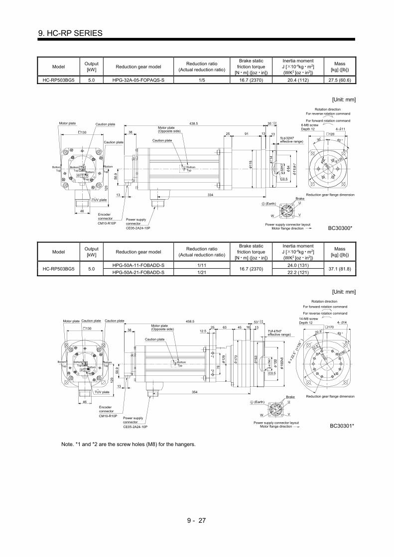
9 - 27
9. HC-RP SERIES
Model Output [kW]
Reduction gear model Reduction ratio
(Actual reduction ratio)
Brake static friction torque
[N m] ([oz in])
Inertia moment J [ 10-4kg m2] (WK2 [oz in2])
Mass [kg] ([lb])
HC-RP503BG5 5.0 HPG-32A-05-FOPAQS-S 1/5 16.7 (2370) 20.4 (112) 27.5 (60.6)
[Unit: mm]
CE05-2A24-10P
13
38
U
VW
9125
4530
C0.5
4- 11
120
BC30300*
438.5 35
1313
334
130
46
0.5 0.4
135
60
A
ED
FG
BC
6-M8 screwDepth 12
For reverse rotation command
For forward rotation command
Rotation direction
Reduction gear flange dimension
Motor flange directionPower supply connector layout
Brake
CM10-R10P
Encoderconnector
Motor plate
Caution plate
Caution plateMotor plate(Opposite side)
Caution plate5( 32H7effective range)
TUV plate
Power supplyconnector
TopBottom
TopBottom
Top
Bottom Top
Bottom
TopBottom
(Earth)
Model Output [kW]
Reduction gear model Reduction ratio
(Actual reduction ratio)
Brake static friction torque
[N m] ([oz in])
Inertia moment J [ 10-4kg m2] (WK2 [oz in2])
Mass [kg] ([lb])
HC-RP503BG5 5.0 HPG-50A-11-FOBADD-S 1/11
16.7 (2370) 24.0 (131)
37.1 (81.8) HPG-50A-21-FOBADD-S 1/21 22.2 (121)
[Unit: mm]
CE05-2A24-10P
13
38
U
VW
6325 45
6
22.5
(=
135
)
170
22.5
22.5 45
4- 14
C0.5
12.5
*1
*2
BC30301*
458.5
354
1316
53
46
130
100
0.5 0.8
A
ED
FG
BC
14-M8 screwDepth 12
For reverse rotation command
For forward rotation command
Rotation direction
Reduction gear flange dimension
Motor flange directionPower supply connector layout
Brake
CM10-R10P
Encoderconnector
Motor plate Caution plateCaution plate
Motor plate(Opposite side)
Caution plate
7( 47H7effective range)
Top
Bottom
Power supplyconnector
TUV plate
TopBottom
TopBottom
Bottom
Top
TopBottom
190
(Earth)
Note. *1 and *2 are the screw holes (M8) for the hangers.
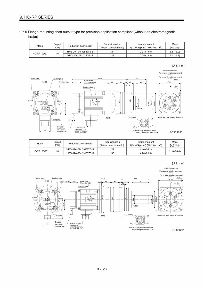
9 - 28
9. HC-RP SERIES
9.7.5 Flange-mounting shaft output type for precision application compliant (without an electromagnetic
brake)
Model Output
[kW] Reduction gear model
Reduction ratio
(Actual reduction ratio)
Inertia moment
J [ 10-4kg m2] (WK2 [oz in2])
Mass
[kg] ([lb])
HC-RP103G7 1.0 HPG-20A-05-J2LBWS-S 1/5 2.37 (13.0) 6.8 (15.0)
HPG-20A-11-J2LBXS-S 1/11 2.25 (12.3) 7.0 (15.4)
[Unit: mm]
F
A
E
C
D H
B
G
38
13U
VW
418
27 42 90
4 9
10
80
31
45
BC30302*
105
227.5
151.5
44Motor flange direction
Power supply connector layout
Reduction gear flange dimension
For reverse rotation command
For forward rotation command
Rotation direction
R0.4
(Earth)
Bottom
Motor plate
EncoderconnectorCM10-R10P
100
TUV plate
Caution plate
Caution plate
Caution plate
Power supplyconnector
CE05-2A22-23P
TopTop
Top
Top
Bottom Bottom
Bottom
Bottom
Top
Motor plate(Opposite side)
Model Output
[kW] Reduction gear model
Reduction ratio
(Actual reduction ratio)
Inertia moment
J [ 10-4kg m2] (WK2 [oz in2])
Mass
[kg] ([lb])
HC-RP103G7 1.0 HPG-32A-21-J2NFSYS-S 1/21 4.40 (24.1)
11.8 (26.0) HPG-32A-33-J2NFSZS-S 1/33 4.20 (23.0)
[Unit: mm]
F
A
E
CD H
B
G
38
13U
VW
4110 4645
R0.4
120133
13 35
13
4 11
82
255.5
179.5
44
135
Motor flange directionPower supply connector layout
Reduction gear flange dimension
For reverse rotation command
For forward rotation command
Rotation direction
BC30303*
Motor plate
EncoderconnectorCM10-R10P
100
TUV plate
Caution plate
Caution plate
Caution plate
Power supplyconnector
Top Top
Top
Top
Bottom
BottomTop
Motor plate(Opposite side)
Bottom Bottom
CE05-2A22-23P
Bottom
(Earth)

9 - 29
9. HC-RP SERIES
Model Output
[kW] Reduction gear model
Reduction ratio
(Actual reduction ratio)
Inertia moment
J [ 10-4kg m2] (WK2 [oz in2])
Mass
[kg] ([lb])
HC-RP103G7 1.0 HPG-50A-45-J2ADBC-S 1/45 6.20 (33.9) 22.9 (50.5)
[Unit: mm]
F
A
E
CD H
B
G
38
13
U
VW
82
156
107 53
R0.4
170
45
4 14268.5
192.5
16
44
Motor flange directionPower supply connector layout
Reduction gear flange dimension
For reverse rotation command
For forward rotation command
Rotation direction
BC30304*
190
13
Bottom
(Earth)EncoderconnectorCM10-R10P
100
TUV plate
Caution plate
Caution plate
Caution plate
Power supplyconnectorCE05-2A22-23P
Top Top
Top
Top
Bottom Bottom
Bottom
Bottom
Motor plate(Opposite side)
Motor plate
Top
Model Output
[kW] Reduction gear model
Reduction ratio
(Actual reduction ratio)
Inertia moment
J [ 10-4kg m2] (WK2 [oz in2])
Mass
[kg] ([lb])
HC-RP153G7 1.5 HPG-20A-05-J2LBWS-S 1/5 2.77 (15.1) 7.9 (17.4)
[Unit: mm]
38
13
WV
U
G
B
HDC
E
A
F
41
8
27 42 90
45
4 910
80
31
252.5
176.5
44
R0.4
BC30305*Motor flange directionPower supply connector layout
Reduction gear flange dimension
For reverse rotation command
For forward rotation command
Rotation direction
105
Motor plate
EncoderconnectorCM10-R10P
100
Caution plate
Caution plate
Caution plate
Power supplyconnectorCE05-2A22-23P
Top Top
Top
Top
Bottom Bottom
Bottom
Bottom
Top
Motor plate(Opposite side)
Bottom
TUV plate
(Earth)
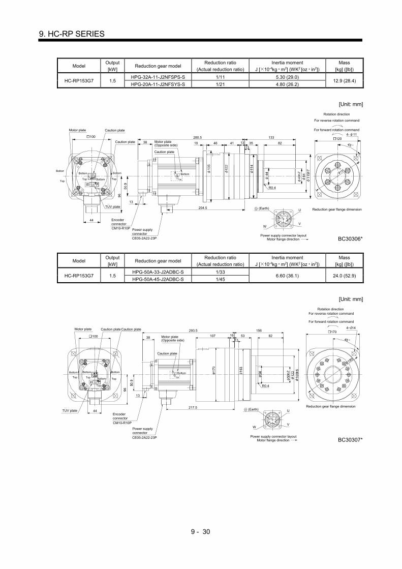
9 - 30
9. HC-RP SERIES
Model Output
[kW] Reduction gear model
Reduction ratio
(Actual reduction ratio)
Inertia moment
J [ 10-4kg m2] (WK2 [oz in2])
Mass
[kg] ([lb])
HC-RP153G7 1.5 HPG-32A-11-J2NFSPS-S 1/11 5.30 (29.0)
12.9 (28.4) HPG-20A-11-J2NFSYS-S 1/21 4.80 (26.2)
[Unit: mm]
38
13
G
B
HDC
E
A
F
4110 46 45
R0.4
133
35
BC30306*
82
280.5
1313
204.5
44
100
Reduction gear flange dimension
WV
U
Motor flange directionPower supply connector layout
(Earth)
Bottom
For reverse rotation command
For forward rotation command
Rotation direction
4- 11 120
CM10-R10P
Encoderconnector
CE05-2A22-23P
Power supplyconnector
Bottom
Top
Motor plate Caution plate
Caution plate
Caution plate
Motor plate(Opposite side)
..TUV plate
Bottom
Top Bottom
Top
Top
Bottom
Top
135
Model Output
[kW] Reduction gear model
Reduction ratio
(Actual reduction ratio)
Inertia moment
J [ 10-4kg m2] (WK2 [oz in2])
Mass
[kg] ([lb])
HC-RP153G7 1.5 HPG-50A-33-J2ADBC-S 1/33
6.60 (36.1) 24.0 (52.9) HPG-50A-45-J2ADBC-S 1/45
[Unit: mm]
38
13
WV
U
G
B
HC
E
A
F
82
156
10713
53
R0.4
170
45
4 14293.5
217.5
16
44Reduction gear flange dimension
BC30307*
190
(Earth)
Bottom
Motor plate
EncoderconnectorCM10-R10P
100
TUV plate
Caution plate Caution plate
Caution plate
Power supplyconnector
CE05-2A22-23P
Top Top Top
Top
Bottom Bottom Bottom
BottomTop
Motor flange directionPower supply connector layout
For reverse rotation command
For forward rotation command
Rotation direction
Motor plate(Opposite side)

9 - 31
9. HC-RP SERIES
Model Output
[kW] Reduction gear model
Reduction ratio
(Actual reduction ratio)
Inertia moment
J [ 10-4kg m2] (WK2 [oz in2])
Mass
[kg] ([lb])
HC-RP203G7 2.0 HPG-20A-05-J2LBWS-S 1/5 3.17 (17.3) 9.1 (20.1)
[Unit: mm]
38
13
WV
U
G
B
HDC
E
A
F
41
8
27 42
R0.4
90
45
4 910
80
31
277.5
201.5
44
BC30308*
Motor plate
Encoderconnector
CM10-R10P
100
TUV plate
Caution plate
Caution plate
Caution plate
Power supplyconnectorCE05-2A22-23P
TopTop
Top
Top
Bottom Bottom
Bottom
Bottom
Top
Motor flange directionPower supply connector layout
Reduction gear flange dimension
For reverse rotation command
For forward rotation command
Rotation direction
Motor plate(Opposite side)
Bottom
105
(Earth)
Model Output
[kW] Reduction gear model
Reduction ratio
(Actual reduction ratio)
Inertia moment
J [ 10-4kg m2] (WK2 [oz in2])
Mass
[kg] ([lb])
HC-RP203G7 2.0 HPG-32A-11-J2NFSPS-S 1/11 5.70 (31.2) 14.1 (31.1)
[Unit: mm]
WV
U
G
B
HDC
E
A
F
R0.4
4 11
135
BC30310*
38
13
4110 46 45
120133
13 3513
82
305.5
229.5
44
Motor plate
EncoderconnectorCM10-R10P
100
TUV plate
Caution plate
Caution plate
Caution plate
Power supplyconnector
CE05-2A22-23P
Top Top
Top
Top
Bottom
BottomTop
Motor flange directionPower supply connector layout
Reduction gear flange dimension
For reverse rotation command
For forward rotation command
Rotation direction
Motor plate(Opposite side)
BottomBottom Bottom
(Earth)

9 - 32
9. HC-RP SERIES
Model Output
[kW] Reduction gear model
Reduction ratio
(Actual reduction ratio)
Inertia moment
J [ 10-4kg m2] (WK2 [oz in2])
Mass
[kg] ([lb])
HC-RP203G7 2.0
HPG-50A-21-J2ADBC-S 1/21 8.0 (43.7)
25.2 (55.6) HPG-50A-33-J2ADBC-S 1/33 7.0 (38.3)
HPG-50A-45-J2ADBC-S 1/45
[Unit: mm]
WV
U
G
B
HDC
E
A
F
R0.4
4 14
BC30311*
190
(Earth)
38
13
82156
10713
53 170
45
318.5
242.5
16
44
Motor plate
Encoderconnector
100
TUV plate
Caution plate
Caution plate
Caution plate
Power supplyconnector
CE05-2A22-23P
TopTop
Top
Top
Bottom Bottom
Bottom
Bottom
Motor flange directionPower supply connector layout
Reduction gear flange dimension
For reverse rotation command
For forward rotation command
Rotation direction
Motor plate(Opposite side)
Bottom
CM10-R10P
Top
Model Output
[kW] Reduction gear model
Reduction ratio
(Actual reduction ratio)
Inertia moment
J [ 10-4kg m2] (WK2 [oz in2])
Mass
[kg] ([lb])
HC-RP353G7 3.5 HPG-32A-05-J2PAQS-S 1/5 13.5 (73.8) 19.9 (43.9)
HPG-32A-11-J2PAR-S 1/11 13.1 (71.6) 20.4 (45.0)
[Unit: mm]
13
38
U
VW
133
829125
R0.4
133513
120
45
4 11
344.5
277
46
BC30312*
A
ED
FG
BC
Motor plate
EncoderconnectorCM10-R10P
130
TUV plate
Caution plate
Caution plate Caution plate
Power supplyconnectorCE05-2A24-10P
Top Top
Top
Top
Bottom Bottom
Bottom
Bottom
Motor flange directionPower supply connector layout
Reduction gear flange dimension
For reverse rotation command
For forward rotation command
Rotation direction
Motor plate(Opposite side)
BottomTop
135
(Earth)

9 - 33
9. HC-RP SERIES
Model Output
[kW] Reduction gear model
Reduction ratio
(Actual reduction ratio)
Inertia moment
J [ 10-4kg m2] (WK2 [oz in2])
Mass
[kg] ([lb])
HC-RP353G7 3.5 HPG-50A-21-J2BADD-S 1/21 15.1 (82.6)
31.1 (68.6) HPG-50A-33-J2BADD-S 1/33 14.1 (77.1)
[Unit: mm]
13
38
U
VW
53
156
25 45
170
4582
4 14
631312.5
1
2
364.5
297
16
46
BC30313*
R0.4
(Earth)
Top
A
ED
FG
BC
Motor plate
Encoderconnector
CM10-R10P
130
TUV plate
Caution plate
Caution plate
Caution plate
CE05-2A24-10P
Top Top
Top
Top
Bottom
Bottom
Motor flange directionPower supply connector layout
Reduction gear flange dimension
For reverse rotation command
For forward rotation command
Rotation direction
Motor plate(Opposite side)
Bottom BottomBottom
Power supplyconnector
190
Note. *1 and *2 are the screw holes (M8) for the hangers.
Model Output
[kW] Reduction gear model
Reduction ratio
(Actual reduction ratio)
Inertia moment
J [ 10-4kg m2] (WK2 [oz in2])
Mass
[kg] ([lb])
HC-RP503G7 5.0 HPG-32A-05-J2PAQS-S 1/5 17.2 (94.0) 24.9 (54.9)
[Unit: mm]
13
38
W V
U
133
829125
R0.4
133513
135
120
45
4 11401.5
334
46
BC30314*
CB
GF
DE
A
Motor plate
EncoderconnectorCM10-R10P
130
TUV plate
Caution plate
Caution plate
Caution plate
Power supplyconnectorCE05-2A24-10P
Top Top
Top
Top
Bottom Bottom
Bottom
Bottom
Motor flange directionPower supply connector layout
Reduction gear flange dimension
For reverse rotation command
For forward rotation command
Rotation direction
Motor plate(Opposite side)
BottomTop
(Earth)

9 - 34
9. HC-RP SERIES
Model Output
[kW] Reduction gear model
Reduction ratio
(Actual reduction ratio)
Inertia moment
J [ 10-4kg m2] (WK2 [oz in2])
Mass
[kg] ([lb])
HC-RP503G7 5.0 HPG-50A-11-J2BADD-S 1/11 20.7 (113)
36.1 (79.6) HPG-50A-21-J2BADD-S 1/21 18.8 (103)
[Unit: mm]
13
38
W V
U
53
156
25 45 170
4582
R0.4
190
4 14
6313
1
12.5
2
421.5
16
354
46
BC30328*
CB
GF
DE
A
Motor plate
EncoderconnectorCM10-R10P
130
TUV plate
Caution plate
Caution plate
Caution plate
Power supplyconnector
CE05-2A24-10P
Top Top
Top
Top
Bottom
Bottom
Motor flange directionPower supply connector layout
Reduction gear flange dimension
For reverse rotation command
For forward rotation command
Rotation direction
Motor plate(Opposite side)
BottomTop
Bottom Bottom
(Earth)
Note. *1 and *2 are the screw holes (M8) for the hangers.
9.7.6 Flange-mounting shaft output type for precision application compliant (with an electromagnetic brake)
Model Output [kW]
Reduction gear model Reduction ratio
(Actual reduction ratio)
Brake static friction torque
[N m] ([oz in])
Inertia moment J [ 10-4kg m2] (WK2 [oz in2])
Mass [kg] ([lb])
HC-RP103BG7 1.0 HPG-20A-05-J2LBWS-S 1/5
7.0 (991) 2.72 (14.9) 8.9 (19.6)
HPG-20A-11-J2LBXS-S 1/11 2.60 (14.2) 9.1 (20.1)
[Unit: mm]
38
50.9
13
WV
UG
B
HDC
E
A
F
25
h7
59
85
h7 84
418
27 42
R0.4
10
80
31
89
265.5
151.5
96
44
105
90
BC30315*
32
(Earth)Brake
4- 9
For reverse rotation command
For forward rotation command
Rotation direction
Motor plate
EncoderconnectorCM10-R10P
100
TUV plate
Caution plate
Caution plate
Caution plate
Power supplyconnector
CE05-2A22-23P
Top Top
Top
Top
BottomBottom
Bottom
Bottom
Top
Motor flange directionPower supply connector layout
Reduction gear flange dimension
Motor plate(Opposite side)
Bottom

9 - 35
9. HC-RP SERIES
Model Output [kW]
Reduction gear model Reduction ratio
(Actual reduction ratio)
Brake static friction torque
[N m] ([oz in])
Inertia moment J [ 10-4kg m2] (WK2 [oz in2])
Mass [kg] ([lb])
HC-RP103BG7 1.0 HPG-32A-21-J2NFSYS-S 1/21
7.0 (991) 4.75 (26.0)
13.9 (30.6) HPG-32A-33-J2NFSZS-S 1/33 4.55 (24.9)
[Unit: mm]
38
50.9
13
WV
UG
B
HDC
E
A
F
4110 4645
40
h7
44
84
11
5h7
11
4
R0.4
120133
13 35
4 11
13
5
82
12
2
293.5
179.5
13
96
44
135
BC30316*
Brake
Motor plate
EncoderconnectorCM10-R10P
100
TUV plate
Caution plate
Caution plate
Caution plate
Power supplyconnector
CE05-2A22-23P
Top Top
Top
Top
Bottom
BottomTop
Motor flange directionPower supply connector layout
Reduction gear flange dimension
For reverse rotation command
For forward rotation command
Rotation direction
Motor plate(Opposite side)
Bottom Bottom Bottom
(Earth)
Model Output [kW]
Reduction gear model Reduction ratio
(Actual reduction ratio)
Brake static friction torque
[N m] ([oz in])
Inertia moment J [ 10-4kg m2] (WK2 [oz in2])
Mass [kg] ([lb])
HC-RP103BG7 1.0 HPG-50A-45-J2ADBC-S 1/45 7.0 (991) 6.55 (35.8) 25.0 (55.1)
[Unit: mm]
38
50.9
13
WV
UG
B
HDC
E
A
F
82
156
16
5h8
16
3
12
2
107
17
0
53
56
R0.4
170
45
50
h7
4 14306.5
192.5
1316
96
44
190
BC30317*
Brake
Motor plate
EncoderconnectorCM10-R10P
100
TUV plate
Caution plate
Caution plate
Caution plate
Power supplyconnectorCE05-2A22-23P
Top Top
Top
Top
Bottom Bottom
Bottom
Bottom
Motor flange directionPower supply connector layout
Reduction gear flange dimension
For reverse rotation command
For forward rotation command
Rotation direction
Motor plate(Opposite side)
BottomTop
(Earth)
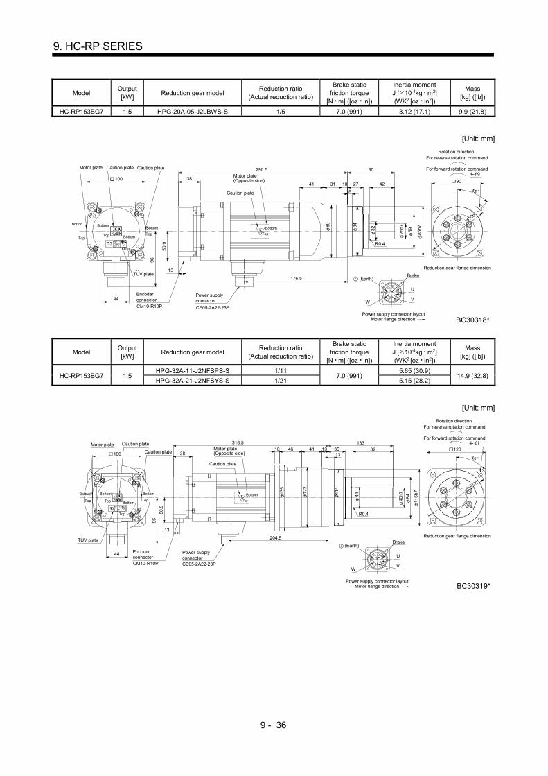
9 - 36
9. HC-RP SERIES
Model Output [kW]
Reduction gear model Reduction ratio
(Actual reduction ratio)
Brake static friction torque
[N m] ([oz in])
Inertia moment J [ 10-4kg m2] (WK2 [oz in2])
Mass [kg] ([lb])
HC-RP153BG7 1.5 HPG-20A-05-J2LBWS-S 1/5 7.0 (991) 3.12 (17.1) 9.9 (21.8)
[Unit: mm]
38
50.9
13
F
A
E
CD H
B
G U
VW
59
85
h7 84
41
8
27 42
R0.4
90
45
4 9
10
80
31
89
290.5
176.5
32
25
h7
96
44
105
BC30318*
Brake
Motor plate
Encoderconnector
CM10-R10P
100
TUV plate
Caution plateCaution plate
Caution plate
Power supplyconnector
CE05-2A22-23P
TopTop
Top
Top
Bottom Bottom
Bottom
Bottom
Top
Motor flange directionPower supply connector layout
Reduction gear flange dimension
For reverse rotation command
For forward rotation command
Rotation direction
Motor plate(Opposite side)
Bottom
(Earth)
Model Output [kW]
Reduction gear model Reduction ratio
(Actual reduction ratio)
Brake static friction torque
[N m] ([oz in])
Inertia moment J [ 10-4kg m2] (WK2 [oz in2])
Mass [kg] ([lb])
HC-RP153BG7 1.5 HPG-32A-11-J2NFSPS-S 1/11
7.0 (991) 5.65 (30.9)
14.9 (32.8) HPG-32A-21-J2NFSYS-S 1/21 5.15 (28.2)
[Unit: mm]
38
50.9
13
F
A
E
CD H
B
G U
VW
4110 46
40
h7
44
84
11
5h7
11
4
R0.4
120133
354 11
13
5
82
12
2
45
318.5
204.5
96
44
BC30319*
1313
Brake
135
Motor plate
EncoderconnectorCM10-R10P
100
TUV plate
Caution plate
Caution plate
Caution plate
Power supplyconnectorCE05-2A22-23P
Top Top
Top
Top
Bottom
BottomTop
Motor flange directionPower supply connector layout
Reduction gear flange dimension
For reverse rotation command
For forward rotation command
Rotation direction
Motor plate(Opposite side)
BottomBottom Bottom
(Earth)

9 - 37
9. HC-RP SERIES
Model Output [kW]
Reduction gear model Reduction ratio
(Actual reduction ratio)
Brake static friction torque
[N m] ([oz in])
Inertia moment J [ 10-4kg m2] (WK2 [oz in2])
Mass [kg] ([lb])
HC-RP153BG7 1.5 HPG-50A-33-J2ADBC-S 1/33
7.0 (991) 6.95 (38.0) 26.0 (57.3) HPG-50A-45-J2ADBC-S 1/45
[Unit: mm]
38
50.9
13
F
A
E
CD H
B
G U
VW
82
156
16
5h8
16
3
12
2
107
17
0
1353
56
170
45
50
h7
4 14331.5
217.5
16
96
44
BC30320*
190
R0.4
Brake
Motor plate
Encoderconnector
CM10-R10P
100
TUV plate
Caution plate
Caution plateCaution plate
Power supplyconnectorCE05-2A22-23P
Top Top
Top
Top
Bottom Bottom
Bottom
Bottom
Motor flange directionPower supply connector layout
Reduction gear flange dimension
For reverse rotation command
For forward rotation command
Rotation direction
Motor plate(Opposite side)
BottomTop
(Earth)
Model Output [kW]
Reduction gear model Reduction ratio
(Actual reduction ratio)
Brake static friction torque
[N m] ([oz in])
Inertia moment J [ 10-4kg m2] (WK2 [oz in2])
Mass [kg] ([lb])
HC-RP203BG7 2.0 HPG-20A-05-J2LBWS-S 1/5 7.0 (991) 3.52 (19.2) 11.2 (24.7)
[Unit: mm]
38
50.9
13
F
A
E
CD H
B
G U
VW
59
85
h7 84
41
8
27 42
32
R0.4
90
45
4 910
80
31
89
315.5
201.5
25
h7
96
44
Caution plate
105
BC30321*
Brake
Motor plate
EncoderconnectorCM10-R10P
100
TUV plate
Caution plate
Caution plate
Power supplyconnector
CE05-2A22-23P
TopTop Top
Top
Bottom Bottom
Bottom
Bottom
Top
Motor flange directionPower supply connector layout
Reduction gear flange dimension
For reverse rotation command
For forward rotation command
Rotation direction
Motor plate(Opposite side)
Bottom
(Earth)

9 - 38
9. HC-RP SERIES
Model Output [kW]
Reduction gear model Reduction ratio
(Actual reduction ratio)
Brake static friction torque
[N m] ([oz in])
Inertia moment J [ 10-4kg m2] (WK2 [oz in2])
Mass [kg] ([lb])
HC-RP203BG7 2.0 HPG-32A-11-J2NFSPS-S 1/11 7.0 (991) 6.05 (33.1) 16.2 (35.7)
[Unit: mm]
38
50.9
13
F
A
E
CD H
B
G U
VW
4110 46
40
h7 44
84
11
5h7
11
4
R0.4
120
133
354 11
13
5
82
12
2
45
343.5
229.5
1313
96
44
BC30322*
Brake
Motor plate
Encoderconnector
CM10-R10P
100
TUV plate
Caution plate
Caution plate
Caution plate
Power supplyconnectorCE05-2A22-23P
Top Top
Top
Top
Bottom
BottomTop
Motor flange directionPower supply connector layout
Reduction gear flange dimension
For reverse rotation command
For forward rotation command
Rotation direction
Motor plate(Opposite side)
BottomBottomBottom
135
(Earth)
Model Output [kW]
Reduction gear model Reduction ratio
(Actual reduction ratio)
Brake static friction torque
[N m] ([oz in])
Inertia moment J [ 10-4kg m2] (WK2 [oz in2])
Mass [kg] ([lb])
HC-RP203BG7 2.0
HPG-50A-21-J2ADBC-S 1/21
7.0 (991)
8.35 (45.7)
27.3 (60.2) HPG-50A-33-J2ADBC-S 1/33 7.35 (40.2)
HPG-50A-45-J2ADBC-S 1/45
[Unit: mm]
38
50.9
13
F
A
E
CD H
B
G U
VW
82156
16
5h8
16
3
12
2
107
17
0
1353
56
R0.4
170
45
50
h7
4 14
16356.5
242.5
96
44
BC30323*
Brake
190
Motor plate
EncoderconnectorCM10-R10P
100
TUV plate
Caution plate
Caution plate
Caution plate
Power supplyconnector
CE05-2A22-23P
Top Top
Top
Top
Bottom Bottom
Bottom
Bottom
Top
Motor flange directionPower supply connector layout
Reduction gear flange dimension
For reverse rotation command
For forward rotation command
Rotation direction
Motor plate(Opposite side)
Bottom
(Earth)

9 - 39
9. HC-RP SERIES
Model Output [kW]
Reduction gear model Reduction ratio
(Actual reduction ratio)
Brake static friction torque
[N m] ([oz in])
Inertia moment J [ 10-4kg m2] (WK2 [oz in2])
Mass [kg] ([lb])
HC-RP353BG7 3.5 HPG-32A-05-J2PAQS-S 1/5
16.7 (2370) 17.0 (92.9) 22.9 (50.5)
HPG-32A-11-J2PAR-S 1/11 16.6 (90.8) 23.4 (51.6)
[Unit: mm]
13
38
W V
U
133
829125
R0.4
35 120
45
4 11381.5
277
46
135
BC30324*
13
13
CB
GF
DE
A
Brake
Motor plate
EncoderconnectorCM10-R10P
130
TUV plate
Caution plate
Caution plate
Caution plate
Power supplyconnector
CE05-2A24-10P
Top Top Top
Top
Bottom Bottom
Bottom
Bottom
Motor flange directionPower supply connector layout
Reduction gear flange dimension
For reverse rotation command
For forward rotation command
Rotation direction
Motor plate(Opposite side)
BottomTop
(Earth)
Model Output [kW]
Reduction gear model Reduction ratio
(Actual reduction ratio)
Brake static friction torque
[N m] ([oz in])
Inertia moment J [ 10-4kg m2] (WK2 [oz in2])
Mass [kg] ([lb])
HC-RP353BG7 3.5 HPG-50A-21-J2BADD-S 1/21
16.7 (2370) 18.6 (102)
34.1 (75.2) HPG-50A-33-J2BADD-S 1/33 17.6 (96.2)
[Unit: mm]
13
38
W V
U
53
156
25 45 170
82
R0.4
4 14
63
1
2
4512.516
13
401.5
297
46
BC30325*
CB
GF
DE
A
Brake
Motor plate
EncoderconnectorCM10-R10P
130
TUV plate
Caution plate
Caution plate
Caution plate
Power supplyconnector
CE05-2A24-10P
Top Top
Top
Top
Bottom
Motor flange directionPower supply connector layout
Reduction gear flange dimension
For reverse rotation command
For forward rotation command
Rotation direction
Motor plate(Opposite side)
BottomTop
BottomBottom
Bottom
190
(Earth)
Note. *1 and *2 are the screw holes (M8) for the hangers.

9 - 40
9. HC-RP SERIES
Model Output [kW]
Reduction gear model Reduction ratio
(Actual reduction ratio)
Brake static friction torque
[N m] ([oz in])
Inertia moment J [ 10-4kg m2] (WK2 [oz in2])
Mass [kg] ([lb])
HC-RP503BG7 5.0 HPG-32A-05-J2PAQS-S 1/5 16.7 (2370) 20.7 (113) 28.9 (63.7)
[Unit: mm]
13
38
U
VW
133
829125
R0.4
133513 120
45
4 11438.5
334
46
BC30326*
A
ED
FG
BC
Brake
Motor plate
Encoderconnector
CM10-R10P
130
TUV plate
Caution plate
Caution plate
Caution plate
Power supplyconnector
CE05-2A24-10P
Top TopTop
Top
Bottom Bottom
Bottom
Bottom
Motor flange directionPower supply connector layout
Reduction gear flange dimension
For reverse rotation command
For forward rotation command
Rotation direction
Motor plate(Opposite side)
BottomTop
135
(Earth)
Model Output [kW]
Reduction gear model Reduction ratio
(Actual reduction ratio)
Brake static friction torque
[N m] ([oz in])
Inertia moment J [ 10-4kg m2] (WK2 [oz in2])
Mass [kg] ([lb])
HC-RP503BG7 5.0 HPG-50A-11-J2BADD-S 1/11
16.7 (2370) 24.2 (132)
40.1 (88.4) HPG-50A-21-J2BADD-S 1/21 22.3 (122)
[Unit: mm]
13
38
U
VW
53
156
25 45 170
45
82
R0.4
4 1463
13
1
12.5
2
458.5
354
16
46
190
BC30327*
A
ED
FG
BC
Brake
Motor plate
EncoderconnectorCM10-R10P
130
TUV plate
Caution plate
Caution plate
Caution plate
Power supplyconnector
CE05-2A24-10P
Top Top
Top
Top
Bottom
Bottom
Motor flange directionPower supply connector layout
Reduction gear flange dimension
For reverse rotation command
For forward rotation command
Rotation direction
Motor plate(Opposite side)
BottomTop
BottomBottom
(Earth)
Note. *1 and *2 are the screw holes (M8) for the hangers.
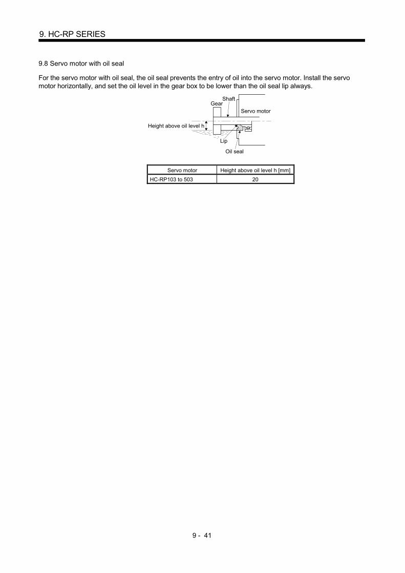
9 - 41
9. HC-RP SERIES
9.8 Servo motor with oil seal
For the servo motor with oil seal, the oil seal prevents the entry of oil into the servo motor. Install the servo motor horizontally, and set the oil level in the gear box to be lower than the oil seal lip always.
GearShaft
Servo motor
Oil seal
Height above oil level h
Lip
Servo motor Height above oil level h [mm]
HC-RP103 to 503 20

9 - 42
9. HC-RP SERIES
MEMO

10 - 1
10. HC-UP SERIES
10. HC-UP SERIES
This chapter provides information on the servo motor specifications and characteristics. When using the HC-
UP series servo motor, always read the Safety Instructions in the beginning of this manual and chapters 1 to 4,
in addition to this chapter.
10.1 Model name make up
The following describes what each block of a model name indicates. Note that not all the combinations of the symbols exist.
HC-UP
Note: Without key
Shaft type
Symbol Shaft shape
NoneStandard
(Straight shaft)
K (Note) With keyway
Appearance
Without
Electromagnetic brake
Symbol Electromagnetic brake
B With
Rated speed2000 [r/min]
2
Series name
None
Rated output
Symbol Rated output [kW]
7 0.75
15 1.5
20 2.0
35 3.5
50 5.0
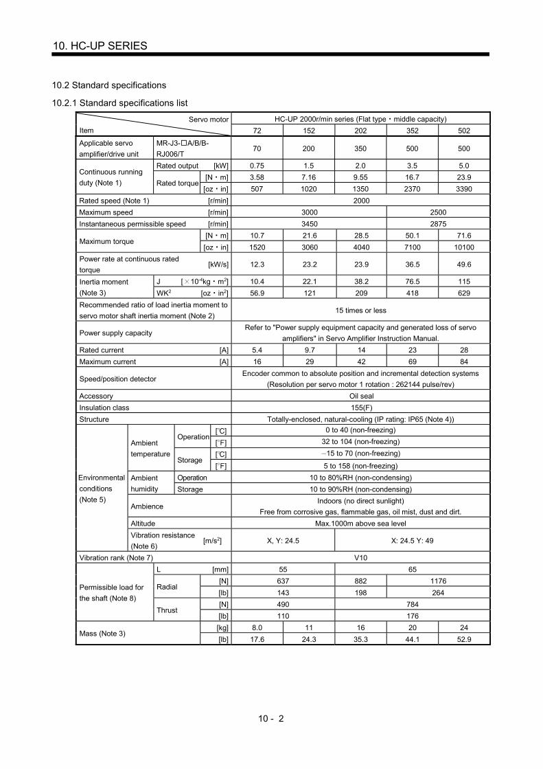
10 - 2
10. HC-UP SERIES
10.2 Standard specifications
10.2.1 Standard specifications list
Servo motor
Item
HC-UP 2000r/min series (Flat type middle capacity)
72 152 202 352 502
Applicable servo
amplifier/drive unit
MR-J3- A/B/B-
RJ006/T 70 200 350 500 500
Continuous running
duty (Note 1)
Rated output [kW] 0.75 1.5 2.0 3.5 5.0
Rated torque [N m] 3.58 7.16 9.55 16.7 23.9
[oz in] 507 1020 1350 2370 3390
Rated speed (Note 1) [r/min] 2000
Maximum speed [r/min] 3000 2500
Instantaneous permissible speed [r/min] 3450 2875
Maximum torque [N m] 10.7 21.6 28.5 50.1 71.6
[oz in] 1520 3060 4040 7100 10100
Power rate at continuous rated
torque [kW/s] 12.3 23.2 23.9 36.5 49.6
Inertia moment
(Note 3)
J [ 10-4kg m2] 10.4 22.1 38.2 76.5 115
WK2 [oz in2] 56.9 121 209 418 629
Recommended ratio of load inertia moment to
servo motor shaft inertia moment (Note 2) 15 times or less
Power supply capacity Refer to "Power supply equipment capacity and generated loss of servo
amplifiers" in Servo Amplifier Instruction Manual.
Rated current [A] 5.4 9.7 14 23 28
Maximum current [A] 16 29 42 69 84
Speed/position detector Encoder common to absolute position and incremental detection systems
(Resolution per servo motor 1 rotation : 262144 pulse/rev)
Accessory Oil seal
Insulation class 155(F)
Structure Totally-enclosed, natural-cooling (IP rating: IP65 (Note 4))
Environmental
conditions
(Note 5)
Ambient
temperature
Operation [ ] 0 to 40 (non-freezing)
[ ] 32 to 104 (non-freezing)
Storage [ ] 15 to 70 (non-freezing)
[ ] 5 to 158 (non-freezing)
Ambient
humidity
Operation 10 to 80%RH (non-condensing)
Storage 10 to 90%RH (non-condensing)
Ambience Indoors (no direct sunlight)
Free from corrosive gas, flammable gas, oil mist, dust and dirt.
Altitude Max.1000m above sea level
Vibration resistance
(Note 6) [m/s2] X, Y: 24.5 X: 24.5 Y: 49
Vibration rank (Note 7) V10
Permissible load for
the shaft (Note 8)
L [mm] 55 65
Radial [N] 637 882 1176
[lb] 143 198 264
Thrust [N] 490 784
[lb] 110 176
Mass (Note 3) [kg] 8.0 11 16 20 24
[lb] 17.6 24.3 35.3 44.1 52.9

10 - 3
10. HC-UP SERIES
Note 1. When the power supply voltage drops, we cannot guarantee the out put and rated speed.
2. If the load inertia moment ratio exceeds the indicated value, please contact your local sales office.
3. Refer to the outline dimension drawing for the servo motor with an electromagnetic brake.
4. Except for the shaft – through portion.
5. In the environment where the servo motor is exposed to oil mist, oil and/or water, the servo motor of the standard specifications
may not be usable. Contact your local sales office.
6. The vibration direction is as shown in the figure. The value is the one at the part that indicates the maximum value (normally the
opposite-to-load side bracket). When the servo motor stops, fretting is likely to occur at the bearing. Therefore, suppress the
vibration to about half of the permissible value.
YX
Servo motor
Vibration Vib
ratio
n am
plit
ude
(b
oth
amp
litud
es)
[ m
]
Speed [r/min]0 1000 2000 3000
10
100
1000
3450
7. V10 indicates that the amplitude of a single servo motor is 10 m or less. The following figure shows the servo motor installation
position for measurement and the measuring position.
Servo motor
Top
Bottom
Measuring position
8. For the symbols in the table, refer to the following diagram: Do not subject the shaft to load greater than this value.
The values in the table assume that the loads work singly.
LRadial load
Thrust load
L: Distance from flange mounting surface to load center

10 - 4
10. HC-UP SERIES
10.2.2 Torque characteristics
POINT
For the system where the unbalanced torque occurs, such as a vertical axis system, the unbalanced torque of the machine should be kept at 70% or less of the rated torque.
When the power input of the servo amplifier are 3-phase 200VAC or 1-phase 230VAC, the torque
characteristic is indicated by the heavy line. For the 1-phase 200VAC power supply, part of the torque
characteristic is indicated by the thin line. HC-UP72 supports 1-phase power supply input.
[HC-UP72]
1000 2000 300000
4
8
12
Speed [r/min]
Continuousrunning range
Short-durationrunning range
Tor
que
[N•m
]
[HC-UP152]
1000 2000 300000
8
16
24
Speed [r/min]
Continuousrunning range
Short-durationrunning range
Tor
que
[N•m
]
[HC-UP202]
1000 2000 300000
10
20
30
Speed [r/min]
Continuousrunning range
Short-durationrunning range
Tor
que
[N•m
]
[HC-UP352]
1000 2000250000
20
40
60
Speed [r/min]
Continuousrunning range
Short-durationrunning range
Tor
que
[N•m
]
[HC-UP502]
1000 2000250000
20
40
80
60
Speed [r/min]
Continuousrunning range
Short-durationrunning range
Tor
que
[N•m
]

10 - 5
10. HC-UP SERIES
10.3 Electromagnetic brake
CAUTION
The electromagnetic brake is provided to prevent a drop at a power failure or alarm
occurrence during vertical drive or to hold a shaft at a stop. Do not use it for normal
braking (including braking at servo lock).
Before performing the operation, be sure to confirm that the electromagnetic brake
operates properly.
The operation time of the electromagnetic brake differs depending on the power
supply circuit you use. Be sure to check the operation delay time with a real
machine.
The characteristics of the electromagnetic brake provided for the servo motor with an electromagnetic brake
are indicated below.
Servo motor
Item
HC-UP series
72B 152B 202B to 502B
Type (Note 1) Spring-loaded safety brake
Rated voltage (Note 4) 24V 010% DC
Capacity [W] at20 (68 ) 19 34
Coil resistance (Note 6) [ ] 29.0 17.0
Inductance (Note 6) [H] 0.8 1.17
Brake static friction torque [N m] 8.5 44
[oz in] 1200 6230
Release delay time (Note 2) [s] 0.04 0.1
Braking delay
time (Note 2) [s] DC off 0.03 0.03
Permissible braking
work
Per braking [J] 400 4500
Per hour [J] 4000 45000
Brake looseness at servo motor shaft (Note 5) [degrees] 0.2 to 0.6 0.2 to 0.6
Brake life (Note 3) Number of braking cycles [times] 20000 20000
Work per braking [J] 200 1000
Selection example of
surge absorbers to be
used (Note 7, 8)
For the suppressed voltage 125V TND20V-680KB
For the suppressed voltage 350V TND10V-221KB
Note 1. There is no manual release mechanism. When it is necessary to hand-turn the servo motor shaft for machine centering, etc.,
use a separate 24VDC power supply to release the brake electrically.
2. The value for initial ON gap at 20 (68 ).
3. The brake gap will increase as the brake lining wears, but the gap is not adjustable. The brake life indicated is the number of
braking cycles after which adjustment will be required.
4. Always prepare a power supply exclusively used for the electromagnetic brake.
5. The above values are typical initial values and not guaranteed values.
6. These values are measured values and not guaranteed values.
7. Select the electromagnetic brake control relay properly, considering the characteristics of the electromagnetic brake and surge
absorber. When a diode is used as a surge absorber, it will take longer to activate the electromagnetic brake.
8. Manufactured by Nippon Chemi-Con Corporation.

10 - 6
10. HC-UP SERIES
10.4 Servo motors with special shafts
The servo motors with special shafts indicated by the symbol (K) in the table is available. K is the symbols
attached to the servo motor model names.
Servo motor Shaft shape
Keyway shaft (without key)
HC-UP K
Servo motor Variable dimensions
S R Q W QK QL U r
HC-UP72(B)K 22h6 55 50 6 -0.0360
42 3 3.5 +0.10
3 HC-UP152(B)K 28h6 55 50 8 -0.036
0 40 3 4 +0.2
0 4 HC-UP202(B)K to 502(B)K
35 +0.0100 65 60 10 -0.036
0 50 5 5 +0.2
0 5
QK
A
Q
R
A
QL UW
r
M8Depth20
S
Section A-A
10.5 Wiring option
Connecter sets to use in power supply connector or brake connector are available as option.
For details of each connector set, cable and connector set to use in wiring to encoder, refer to the Servo
Amplifier Instruction Manual for using.
Make sure to use the following power supply connector set for conforming to the IEC/EN compliant.
Servo motor Power supply connector set Brake connector set
HC-UP72 152
MR-PWCNS1
Shared with the one for power supply
(Note)
Configuration products
Plug: CE05-6A22-23SD-D-BSS
Cable clamp: CE3057-12A-2-D
(DDK)
HC-UP202 to 502
MR-PWCNS2 MR-BKCN
Configuration products
Plug: CE05-6A24-10SD-D-BSS
Cable clamp: CE3057-16A-2-D
(DDK)
Configuration products
Plug: D/MS3106A10SL-4S (D190)
(DDK)
Connector for cable: YSO10-5 to 8
(Daiwa Dengyo)
Note. Brake connector is not required since the power supply connector has a pin assigned for
electromagnetic brake.

10 - 7
10. HC-UP SERIES
10.6 Outline dimension drawings
The dimensions without tolerances are reference dimensions.
Inertia moment on the table is the value calculated by converting the total value of inertia moment for servo
motor, electromagnetic brake and decelerator with servo motor shaft.
10.6.1 Standard (without an electromagnetic brake)
Model Output
[kW]
Inertia moment
J [ 10-4kg m2]
(WK2 [oz in2])
Mass
[kg] ([lb])
HC-UP72 0.75 10.4 (56.9) 8.0 (17.6)
[Unit: mm]
38
176
13
CE05-2A22-23P
CM10-R10P
109 55
50
13 3
38 44
BC29502*
S30457B
2-M6 screw
WV
U
G
B
HDC
E
A
F
(Earth)
Bottom
Top
Bottom
Top
Power supply connector
Motor plate
(Opposite side)
Encoder connector
Caution plate
4- 13.5 mounting hole
Use hexagon sockethead cap screw
Power supply connector layoutMotor flange direction
Bottom
Top
Bottom
Top
Oil seal
Motor plate Caution plateCaution plate
Model Output
[kW]
Inertia moment
J [ 10-4kg m2]
(WK2 [oz in2])
Mass
[kg] ([lb])
HC-UP152 1.5 22.1 (121) 11 (24.3)
[Unit: mm]
38
176
13
CE05-2A22-23P
CM10-R10P
118.5 55
50
13 3
47.5
4540
200 230
215
44
S30457B
2-M6 screw
F
A
E
CD H
B
G
U
VW
BC29503*
Motor plate
(Opposite side)
(Earth)Encoder connector
Caution plate
Caution plate
Motor plate
Bottom
Top
Bottom
Top
Bottom
Top
Bottom
Top
Power supply connector
4- 13.5 mounting holeUse hexagon socket
head cap screw
Power supply connector layoutMotor flange direction
Caution plate
Oil seal

10 - 8
10. HC-UP SERIES
Model Output
[kW]
Inertia moment
J [ 10-4kg m2]
(WK2 [oz in2])
Mass
[kg] ([lb])
HC-UP202 2.0 38.2 (209) 16 (35.3)
[Unit: mm]
CE05-2A24-10P
CM10-R10P
S40608B
47
BC29504*
220
4537.5
235
250
270
2-M8 Screw
38
116.5
16 4
65
60
42.5
13
W V
U
4- 13.5 mounting holeUse hexagon socket
head cap screw
(Earth)
CB
GF
DE
A
Bottom
Top
Bottom
Top
Power supply connector
Motor plate
(Opposite side)
Encoder connector
Power supply connector layoutMotor flange direction
Bottom
Top
Bottom
Top
Oil seal
Motor plate Caution plate
Caution plate
Caution plate
Model Output
[kW]
Inertia moment
J [ 10-4kg m2]
(WK2 [oz in2])
Mass
[kg] ([lb])
HC-UP352 3.5 76.5 (418) 20 (44.1)
[Unit: mm]
CE05-2A24-10P
CM10-R10P
S40608B
47
BC29505*
220
4537.5
235
250
270
38
140.5
16 4
65
60
66.5
13
U
VW
(Earth)
A
ED
FG
BC
2-M8 screw
Bottom
Top
Power supply connector
Encoder connector
Caution plate
4- 13.5 mounting holeUse hexagon socket
head cap screw
Power supply connector layoutMotor flange direction
Bottom
Top
Bottom
Top
Bottom
Top
Oil seal
Motor plate Caution plate
Motor plate(Opposite side)
Caution plate

10 - 9
10. HC-UP SERIES
Model Output
[kW]
Inertia moment
J [ 10-4kg m2]
(WK2 [oz in2])
Mass
[kg] ([lb])
HC-UP502 5.0 115 (629) 24 (52.9)
[Unit: mm]
CE05-2A24-10P
CM10-R10P
S40608B
47
BC29506*
220
4537.5
235
250
270
38
164.5
16 4
65
60
90.5
13
U
VWA
ED
FG
BC
2-M8 screw
Power supply connector
Encoder connector
Caution plate
4- 13.5 mounting hole
Use hexagon sockethead cap screw
Bottom
Top
Bottom
Top
Bottom
Top
Oil seal
Motor plate Caution plate
Power supply connector layoutMotor flange direction
Bottom
Top
Motor plate
(Opposite side)
Caution plate
(Earth)
10.6.2 With an electromagnetic brake
Model Output
[kW]
Brake static friction
torque [N m]
([oz in])
Inertia moment
J [ 10-4kg m2]
(WK2 [oz in2])
Mass
[kg] ([lb])
HC-UP72B 0.75 8.5 (1200) 12.5 (68.3) 10 (22.0)
[Unit: mm]
38
176
13
CE05-2A22-23P
CM10-R10P
142.5 55
50
13 3
38
4540
200 230
215
44
BC29517*
S30457B
F
A
E
CD H
B
G U
VW
Brake
2-M6 screw
(Earth)
Bottom
Top
Bottom
Top
Power supply connector
Encoder connector
4- 13.5 mounting holeUse hexagon socket
head cap screw
Power supply connector layoutMotor flange direction
Bottom
Top
Bottom
Top
Oil seal
Motor plate Caution plate
Caution plate
Motor plate
(Opposite side)
Caution plate

10 - 10
10. HC-UP SERIES
Model Output
[kW]
Brake static friction
torque [N m]
([oz in])
Inertia moment
J [ 10-4kg m2]
(WK2 [oz in2])
Mass
[kg] ([lb])
HC-UP152B 1.5 8.5 (1200) 24.2 (132) 13 (28.7)
[Unit: mm]
38
13
152 55
50
3
S30457B
Caution plate
176
CE05-2A22-23P
CM10-R10P
13
47.5
4540
200 230
215
44
BC29518*
Brake
W V
UG
B
HDC
E
A
F
2-M6 screw
Bottom
Top
Power supply connector
Encoder connector
4- 13.5 mounting hole
Use hexagon socket
head cap screw
Power supply connector layoutMotor flange direction
Bottom
Top
Bottom
Top
Motor plate Caution plate
Oil seal
Motor plate
(Opposite side)
Caution plate
Bottom
Top
(Earth)
Model Output
[kW]
Brake static friction
torque [N m]
([oz in])
Inertia moment
J [ 10-4kg m2]
(WK2 [oz in2])
Mass
[kg] ([lb])
HC-UP202B 2.0 44 (6230) 46.8 (256) 22 (48.5)
[Unit: mm]
CM10-R10P
S40608B
47
BC29519*
220
4537.5
235
250
270
38
159.5
16 4
65
60
42.5
13
42
53.5
MS3102A10SL-4P
W V
U (Earth)
CB
GF
DE
A
AB
Power supply
connector
Encoder connector
Brake connector
Brake connector layout
Brake
Motor flange direction
Motor plate
(Opposite side)
Caution plate
4- 13.5 mounting hole
Use hexagon socket
head cap screw
Power supply connector layoutMotor flange direction
Bottom
Top
Oil seal
Motor plate Caution plateCaution plate
Bottom
Top
Bottom
Top
Bottom
Top
2-M8 screw
CE05-2A24-10P

10 - 11
10. HC-UP SERIES
Model Output
[kW]
Brake static friction
torque [N m]
([oz in])
Inertia moment
J [ 10-4kg m2]
(WK2 [oz in2])
Mass
[kg] ([lb])
HC-UP352B 3.5 44 (6230) 85.1 (465) 26 (57.3)
[Unit: mm]
CE05-2A24-10P
CM10-R10P
S40608B
47
BC29520*
220
4537.5
235
250
270
38
183.5
16 4
65
60
66.5
13
42
53.5
MS3102A10SL-4P
U
VWBA
A
ED
FG
BC
(Earth)Encoder connector
Brake connector
Brake connector layout
Brake
Motor flange direction
Motor plate
(Opposite side)
Caution plate
4- 13.5 mounting hole
Use hexagon socket
head cap screw
Power supply connector layoutMotor flange direction
Bottom
Top
Oil seal
Motor plate Caution plate Caution plate
Bottom
Top
BottomTop
2-M6 screw
Power supply
connector
Model Output
[kW]
Brake static friction
torque [N m]
([oz in])
Inertia moment
J [ 10-4kg m2]
(WK2 [oz in2])
Mass
[kg] ([lb])
HC-UP502B 5.0 44 (6230) 124 (678) 30 (66.1)
[Unit: mm]
CE05-2A24-10P
CM10-R10P
S40608B
47
BC29521*
220
4537.5
235
250
270
38
207.5
16 4
65
60
90.5
13
42
53.5
MS3102A10SL-4P
U
VW
(Earth)
BA
A
ED
FG
BC
Encoder connector
Brake connector
Brake connector layout
Brake
Motor flange direction
Motor plate
(Opposite side)
Caution plate
4- 13.5 mounting hole
Use hexagon sockethead cap screw
Power supply connector layoutMotor flange direction
Bottom
Top
Oil seal
Motor plate Caution plateCaution plate
Bottom
Top
Bottom
Top
Bottom
Top
2-M8 screw
Power supply
connector

10 - 12
10. HC-UP SERIES
10.7 Servo motor with oil seal
For the servo motor with oil seal, the oil seal prevents the entry of oil into the servo motor. Install the servo motor horizontally, and set the oil level in the gear box to be lower than the oil seal lip always.
GearShaft
Servo motor
Oil seal
Height above oil level h
Lip
Servo motor Height above oil level h [mm]
HC-UP72 152 20
HC-UP202 to 502 25
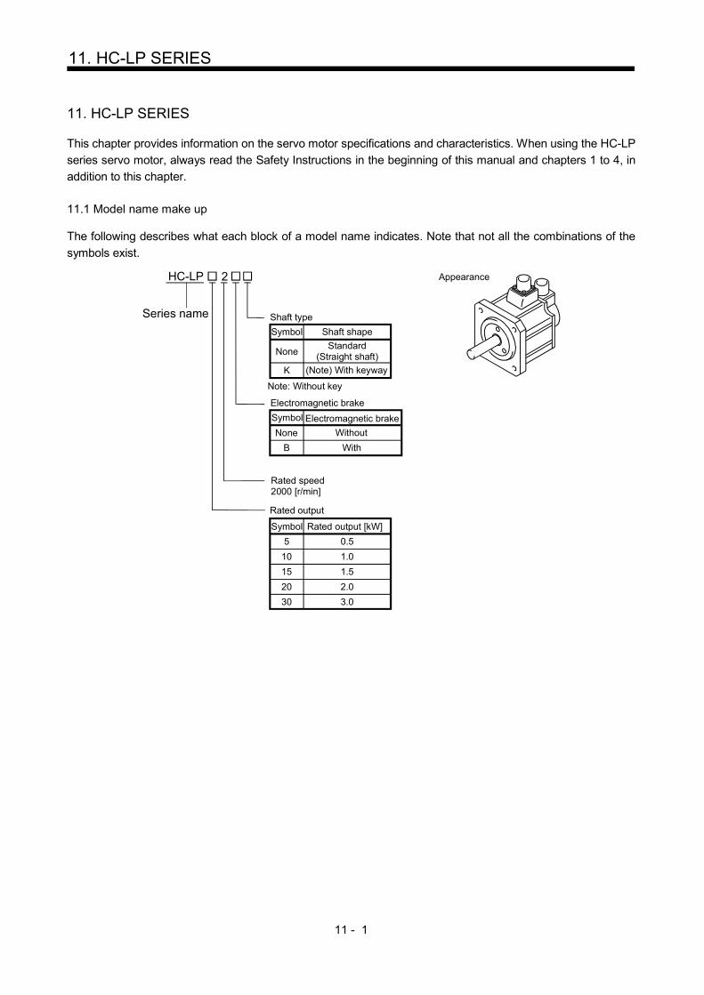
11 - 1
11. HC-LP SERIES
11. HC-LP SERIES
This chapter provides information on the servo motor specifications and characteristics. When using the HC-LP
series servo motor, always read the Safety Instructions in the beginning of this manual and chapters 1 to 4, in
addition to this chapter.
11.1 Model name make up
The following describes what each block of a model name indicates. Note that not all the combinations of the
symbols exist.
HC-LP
Note: Without key
Shaft type
Symbol Shaft shape
NoneStandard
(Straight shaft)
K (Note) With keyway
Appearance
Without
Electromagnetic brake
Symbol Electromagnetic brake
B With
Rated speed2000 [r/min]
2
Series name
None
5 0.5
Rated output
Symbol Rated output [kW]
10 1.0
15 1.5
20 2.0
30 3.0

11 - 2
11. HC-LP SERIES
11.2 Standard specifications
11.2.1 Standard specifications list
Servo motor
Item
HC-LP series (Low inertia middle capacity)
52 102 152 202 302
Applicable servo
amplifier/drive unit
MR-J3- A/B/B-
RJ006/T 60 100 200 350 500
Continuous running
duty (Note 1)
Rated
output [kW] 0.5 1.0 1.5 2.0 3.0
Rated
torque
[N m] 2.39 4.78 7.16 9.55 14.3
[oz in] 339 677 1010 1350 2030
Rated speed (Note 1) [r/min] 2000
Maximum speed [r/min] 3000
Instantaneous permissible speed [r/min] 3450
Maximum torque [N m] 7.16 14.4 21.6 28.5 42.9
[oz in] 1010 2040 3060 4040 6080
Power rate at continuous rated
torque [kW/s] 17.9 49.7 80.1 41.5 56.8
Inertia moment
(Note 3)
J [ 10-4kg m2] 3.10 4.62 6.42 22.0 36.0
WK2 [oz in2] 16.9 25.3 35.1 120 197
Recommended ratio of load inertia moment to
servo motor shaft inertia moment (Note 2) 10 times or less
Power supply capacity Refer to "Power supply equipment capacity and generated loss of servo
amplifiers" in Servo Amplifier Instruction Manual.
Rated current [A] 3.2 5.9 9.9 14 23
Maximum current [A] 9.6 18 30 42 69
Speed/position detector Encoder common to absolute position and incremental detection systems
(Resolution per servo motor 1 rotation : 262144 pulse/rev)
Accessory Oil seal
Insulation class 155(F)
Structure Totally-enclosed, natural-cooling (IP rating: IP65 (Note 4))
Environmental
conditions
(Note 5)
Ambient
temperature
Operation [ ] 0 to 40 (non-freezing)
[ ] 32 to 104 (non-freezing)
Storage [ ] 15 to 70 (non-freezing)
[ ] 5 to 158 (non-freezing)
Ambient
humidity
Operation 10 to 80%RH (non-condensing)
Storage 10 to 90%RH (non-condensing)
Ambience Indoors (no direct sunlight)
Free from corrosive gas, flammable gas, oil mist, dust and dirt.
Altitude Max.1000m above sea level
Vibration resistance
(Note 6) [m/s2] X: 9.8 Y: 24.5 X: 19.6 Y: 49
Vibration rank (Note 7) V10
Permissible
load for the
shaft
(Note 8)
L [mm] 55 79
Radial [N] 980 2060
[lb] 220 463
Thrust [N] 490 980
[lb] 110 220
Mass (Note 3) [kg] 6.5 8.0 10 21 28
[lb] 14.3 17.6 22.0 46.3 61.7

11 - 3
11. HC-LP SERIES
Note 1. When the power supply voltage drops, we cannot guarantee the out put and rated speed.
2. If the load inertia moment ratio exceeds the indicated value, please contact your local sales office.
3. Refer to the outline dimension drawing for the servo motor with an electromagnetic brake.
4. Except for the shaft – through portion.
5. In the environment where the servo motor is exposed to oil mist, oil and/or water, the servo motor of the standard specifications
may not be usable. Contact your local sales office.
6. The vibration direction is as shown in the figure. The value is the one at the part that indicates the maximum value (normally the
opposite-to-load side bracket). When the servo motor stops, fretting is likely to occur at the bearing. Therefore, suppress the
vibration to about half of the permissible value.
YX
Servo motor
Vibration 0 1000 2000 300010
100
1000V
ibra
tion
ampl
itude
(b
oth
amp
litud
es)
[ m
]
Speed [r/min]
7. V10 indicates that the amplitude of a single servo motor is 10 m or less. The following figure shows the servo motor installation
position for measurement and the measuring position.
Servo motor
Top
Bottom
Measuring position
8. For the symbols in the table, refer to the following diagram: Do not subject the shaft to load greater than this value.
The values in the table assume that the loads work singly.
LRadial load
Thrust load
L: Distance from flange mounting surface to load center
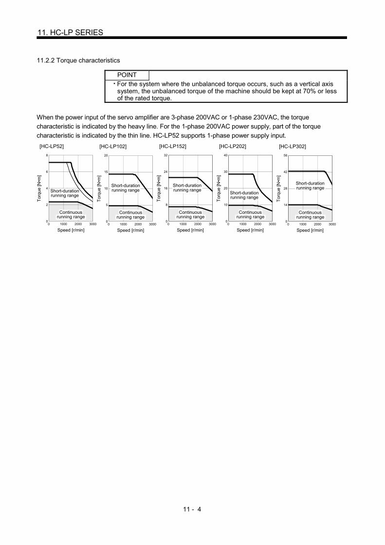
11 - 4
11. HC-LP SERIES
11.2.2 Torque characteristics
POINT
For the system where the unbalanced torque occurs, such as a vertical axis system, the unbalanced torque of the machine should be kept at 70% or less of the rated torque.
When the power input of the servo amplifier are 3-phase 200VAC or 1-phase 230VAC, the torque
characteristic is indicated by the heavy line. For the 1-phase 200VAC power supply, part of the torque
characteristic is indicated by the thin line. HC-LP52 supports 1-phase power supply input.
[HC-LP52]
8
6
4
2
00 1000 2000 3000
Speed [r/min]
Tor
que
[N•m
]
Short-durationrunning range
Continuousrunning range
[HC-LP102]
1000 2000 300000
5
10
20
15
Speed [r/min]
Continuousrunning range
Short-durationrunning range
Tor
que
[N•m
]
[HC-LP152]
1000 2000 300000
8
32
24
16
Speed [r/min]
Continuousrunning range
Short-durationrunning range
Tor
que
[N•m
]
[HC-LP202]
1000 2000 300000
10
40
30
20
Speed [r/min]
Continuousrunning range
Short-durationrunning range
Tor
que
[N•m
]
[HC-LP302]
1000 2000 300000
14
56
28
42
Speed [r/min]
Continuousrunning range
Short-durationrunning range
Tor
que
[N•m
]

11 - 5
11. HC-LP SERIES
11.3 Electromagnetic brake
CAUTION
The electromagnetic brake is provided to prevent a drop at a power failure or alarm
occurrence during vertical drive or to hold a shaft at a stop. Do not use it for normal
braking (including braking at servo lock).
Before performing the operation, be sure to confirm that the electromagnetic brake
operates properly.
The operation time of the electromagnetic brake differs depending on the power
supply circuit you use. Be sure to check the operation delay time with a real
machine.
The characteristics of the electromagnetic brake provided for the servo motor with an electromagnetic brake
are indicated below.
Servo motor
Item
HC-LP series
52B to 152B 202B 302B
Type (Note 1) Spring-loaded safety brake
Rated voltage (Note 4) 24V 010% DC
Capacity [W] at20 (68 ) 19 34
Coil resistance (Note 6) [ ] 29.0 17.0
Inductance (Note 6) [H] 0.80 1.17
Brake static friction torque [N m] 8.5 44
[oz in] 1200 6230
Release delay time (Note 2) [s] 0.04 0.1
Braking delay
time (Note 2) [s] DC off 0.03 0.03
Permissible braking
work
Per braking [J] 400 4500
Per hour [J] 4000 45000
Brake looseness at servo motor shaft (Note 5) [degrees] 0.2 to 0.6 0.2 to 0.6
Brake life (Note 3) Number of braking cycles [times] 20000 20000
Work per braking [J] 200 1000
Selection example of
surge absorbers to
be used (Note 7, 8)
For the suppressed voltage 125V TND20V-680KB
For the suppressed voltage 350V TND10V-221KB
Note 1. There is no manual release mechanism. When it is necessary to hand-turn the servo motor shaft for machine centering, etc.,
use a separate 24VDC power supply to release the brake electrically.
2. The value for initial ON gap at 20 (68 ).
3. The brake gap will increase as the brake lining wears, but the gap is not adjustable. The brake life indicated is the number of
braking cycles after which adjustment will be required.
4. Always prepare a power supply exclusively used for the electromagnetic brake.
5. The above values are typical initial values and not guaranteed values.
6. These values are measured values and not guaranteed values.
7. Select the electromagnetic brake control relay properly, considering the characteristics of the electromagnetic brake and surge
absorber. When a diode is used as a surge absorber, it will take longer to activate the electromagnetic brake.
8. Manufactured by Nippon Chemi-Con Corporation.

11 - 6
11. HC-LP SERIES
11.4 Servo motors with special shafts
The servo motors with special shafts indicated by the symbol (K) in the table is available. K is the symbols
attached to the servo motor model names.
Servo motor Shaft shape
Keyway shaft (without key)
HC-LP K
Servo motor Variable dimensions
S R Q W QK QL U r
HC-LP52(B)K to 152(B)K
24h6 55 50 800.036 36 5 4 0.2
0 4
HC-LP202(B)K 302(B)K
35 0.0100 79 75 10 0
0.036 55 5 5 0.20 5
QK
A
Q
R
A
QL UW
r
M8Depth20
S
Section A-A
11.5 Wiring option
Connecter sets to use in power supply connector or brake connector are available as option.
For details of each connector set, cable and connector set to use in wiring to encoder, refer to the Servo
Amplifier Instruction Manual for using.
Make sure to use the following power supply connector set for conforming to the IEC/EN compliant.
Servo motor Power supply connector set Brake connector set
HC-LP52 to 152
MR-PWCNS1
Shared with the one for power supply
(Note)
Configuration products
Plug: CE05-6A22-23SD-D-BSS
Cable clamp: CE3057-12A-2-D
(DDK)
HC-LP202 302
MR-PWCNS2 MR-BKCN
Configuration products
Plug: CE05-6A24-10SD-D-BSS
Cable clamp: CE3057-16A-2-D
(DDK)
Configuration products
Plug: D/MS3106A10SL-4S (D190)
(DDK)
Connector for cable: YSO10-5 to 8
(Daiwa Dengyo)
Note. Brake connector is not required since the power supply connector has a pin assigned for
electromagnetic brake.

11 - 7
11. HC-LP SERIES
11.6 Outline dimension drawings
The dimensions without tolerances are reference dimensions.
Inertia moment on the table is the value calculated by converting the total value of inertia moment for servo
motor, electromagnetic brake and decelerator with servo motor shaft.
11.6.1 Standard (without an electromagnetic brake)
Model Output
[kW]
Inertia moment
J [ 10-4kg m2]
(WK2 [oz in2])
Mass
[kg] ([lb])
HC-LP52 0.5 3.10 (16.9) 6.5 (14.3)
[Unit: mm]
50
55
CE05-2A22-23P
77
144
S30457B
130
13
CM10-R10P
38
12 3
44
BC29507*
V
U
G
B
HDC
E
A
F
Caution plate
Caution plate
Caution plate
BottomBottom
Motor plate
Bottom
Top
Encoder connector
Power supply connector
TopTop
Bottom
Top
Motor plate(Oppositeside)
Oil seal
W
4- 9 mounting hole
Use hexagon sockethead cap screw
165 145
45
(Earth)
Model Output
[kW]
Inertia moment
J [ 10-4kg m2]
(WK2 [oz in2])
Mass
[kg] ([lb])
HC-LP102 1.0 4.62(25.3) 8.0 (17.6)
[Unit: mm]
50
55
CE05-2A22-23P
97
164
S30457B
130
13
CM10-R10P
38
12 3
44
BC29508*
F
A
E
CD H
B
G
U
V
Motor plate
Encoder connector
Oil seal
165
4- 9 mounting holeUse hexagon sockethead cap screw
(Earth)
Caution plate
Bottom
Top
Bottom
Top
Motor plate Caution plate
Caution plate
Bottom
Top
Bottom
Top
(Oppositeside)
Power supply connectorW
145
45
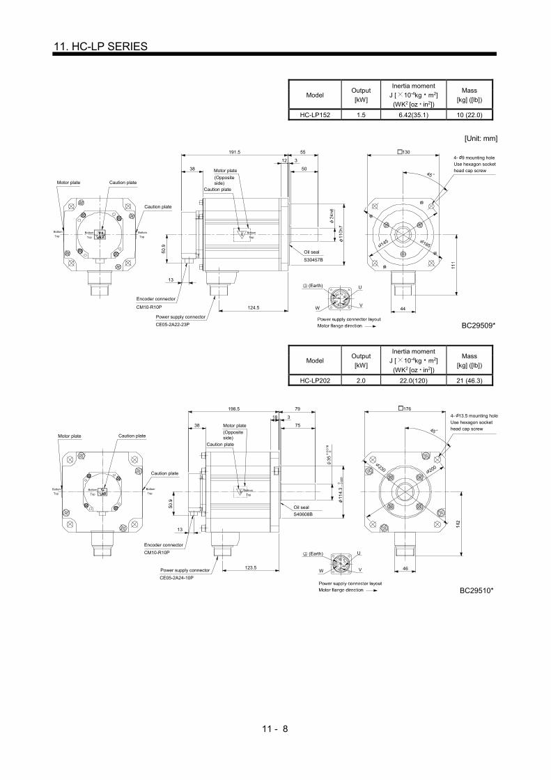
11 - 8
11. HC-LP SERIES
Model Output
[kW]
Inertia moment
J [ 10-4kg m2]
(WK2 [oz in2])
Mass
[kg] ([lb])
HC-LP152 1.5 6.42(35.1) 10 (22.0)
[Unit: mm]
50
55
CE05-2A22-23P
124.5
191.5
S30457B
130
13
CM10-R10P
38
12 3
44
BC29509*
F
A
E
CD H
B
G
V
Motor plate Caution plate
Caution plate
Encoder connector
Power supply connector
Oil seal
4- 9 mounting holeUse hexagon sockethead cap screw
45
145
(Earth)
Bottom
Top
Bottom
TopBottom
Top
Bottom
Top
Caution plate
(Oppositeside)
Motor plate
W
U
165
Model Output
[kW]
Inertia moment
J [ 10-4kg m2]
(WK2 [oz in2])
Mass
[kg] ([lb])
HC-LP202 2.0 22.0(120) 21 (46.3)
S40608B
123.5
318
75
79198.5
CM10-R10P
13
176
38
46
BC29510*
CE05-2A24-10P
V
Motor plate
Encoder connector
Power supply connector
Motor plate
Oil seal
45
4- 13.5 mounting hole
Use hexagon sockethead cap screw
(Earth)
A
ED
FG
BC
Bottom
Top
Bottom
Top
Bottom
TopBottom
Top
Caution plate
Caution plate
(Oppositeside)
Caution plate
W
U
200
230

11 - 9
11. HC-LP SERIES
Model Output
[kW]
Inertia moment
J [ 10-4kg m2]
(WK2 [oz in2])
Mass
[kg] ([lb])
HC-LP302 3.0 36.0(197) 28 (61.7)
[Unit: mm]
173.5
318
75
79248.5
13
38
46
BC29511*
*1*2
U
VW
(Earth)
A
ED
FG
BC
S40608B
CM10-R10P
CE05-2A24-10P
Motor plate
Encoder connector
Power supply connector
Motor plate
Oil seal
45
4- 13.5 mounting holeUse hexagon socket
head cap screw
176
Bottom
Top
Bottom
TopBottom
Top
Caution plate
Caution plate
(Opposite side)
Caution plate
200
230
Bottom
Top
11.6.2 With an electromagnetic brake
Model Output
[kW]
Brake static friction
torque [N m]
([oz in])
Inertia moment
J [ 10-4kg m2]
(WK2 [oz in2])
Mass
[kg] ([lb])
HC-LP52B 0.5 8.5 (1200) 5.20 (28.4) 9.0 (19.8)
[Unit: mm]
50
55
77
177
13
38
12 3
44
BC29522*
F
A
E
CD H
B
G
U
VW
(Earth)
CM10-R10P
CE05-2A22-23P
Motor plate
Encoder connector
Power supply connector
Motor plate45
4- 9 mounting holeUse hexagon sockethead cap screw
130
Bottom
Top
Bottom
TopBottom
Top
Caution plate
Caution plate
(Opposite side)
Caution plate
145 165
Bottom
Top
S30457B
Oil seal
Brake

11 - 10
11. HC-LP SERIES
Model Output
[kW]
Brake static friction
torque [N m]
([oz in])
Inertia moment
J [ 10-4kg m2]
(WK2 [oz in2])
Mass
[kg] ([lb])
HC-LP102B 1.0 8.5 (1200) 6.72 (36.7) 11 (24.3)
[Unit: mm]
50
55
97
197
13
38
12 3
44
BC29523*
WV
U
G
B
HDC
E
A
F
(Earth)
CM10-R10P
CE05-2A22-23P
Motor plate
Encoder connector
Power supply connector
Motor plate45
4- 9 mounting holeUse hexagon socket
head cap screw
130
Bottom
Top
Bottom
Top
Bottom
Top
Caution plate
Caution plate
(Opposite side)
Caution plate
145
165
Bottom
Top
S30457B
Oil seal
Brake
Model Output
[kW]
Brake static friction
torque [N m]
([oz in])
Inertia moment
J [ 10-4kg m2]
(WK2 [oz in2])
Mass
[kg] ([lb])
HC-LP152B 1.5 8.5 (1200) 8.52 (46.6) 13 (28.7)
[Unit: mm]
50
55
124.5
224.5
13
38
12 3
44
BC29524*
WV
U
G
B
HDC
E
A
F
(Earth)
CM10-R10P
CE05-2A22-23P
Motor plate
Encoder connector
Power supply connector
Motor plate45
4- 9 mounting holeUse hexagon socket
head cap screw
130
Bottom
Top
Bottom
TopBottom
Top
Caution plate
Caution plate
(Opposite side)
Caution plate
145 165
Bottom
Top
S30457BOil seal
Brake

11 - 11
11. HC-LP SERIES
Model Output
[kW]
Brake static friction
torque [N m]
([oz in])
Inertia moment
J [ 10-4kg m2]
(WK2 [oz in2])
Mass
[kg] ([lb])
HC-LP202B 2.0 44 (6230) 32.0 (175) 27 (59.5)
[Unit: mm]
123.5
318
75
79246.5
13
38
46
BC29525*
67.5
MS3102A10SL-4P
W V
U (Earth)
CB
GF
DE
A
ABCM10-R10P
CE05-2A24-10P
Motor plate
Encoder connector
Power supply
Motor plate
Brake
45
176
Bottom
Top
Bottom
Top
Bottom
Top
Caution plate
Caution plate(Opposite side)
Caution plate
200
230
Bottom
Top
S40608B
Oil seal
Brake connector
Power supply connector layout
Motor flange directionBrake connector layoutMotor flange direction
4- 13.5 mounting holeUse hexagon sockethead cap screw
connector
Model Output
[kW]
Brake static friction
torque [N m]
([oz in])
Inertia moment
J [ 10-4kg m2]
(WK2 [oz in2])
Mass
[kg] ([lb])
HC-LP302B 3.0 44 (6230) 46.0 (252) 34 (75.0)
[Unit: mm]
173.5
318
75
79296.5
13
38
46
BC29526*
*1*2
67.5 U
VW
(Earth)
BA
A
ED
FG
BC
MS3102A10SL-4P
CM10-R10P
CE05-2A24-10P
Motor plate
Encoder connector
Motor plate
Brake
45
176
Bottom
Top
Bottom
TopBottom
Top
Caution plate
Caution plate(Opposite side)
Caution plate
200
230
Bottom
Top
S40608B
Oil seal
Brake connector
Power supply connector layout
Motor flange directionBrake connector layoutMotor flange direction
4- 13.5 mounting hole
Use hexagon socket
head cap screw
Power supplyconnector
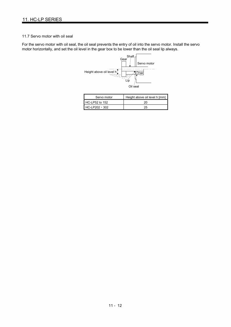
11 - 12
11. HC-LP SERIES
11.7 Servo motor with oil seal
For the servo motor with oil seal, the oil seal prevents the entry of oil into the servo motor. Install the servo motor horizontally, and set the oil level in the gear box to be lower than the oil seal lip always.
GearShaft
Servo motor
Oil seal
Height above oil level h
Lip
Servo motor Height above oil level h [mm]
HC-LP52 to 152 20
HC-LP202 302 25

12 - 1
12. HF-JP SERIES
12. HF-JP SERIES
This chapter provides information on the servo motor specifications and characteristics. When using the HF-JP
series servo motor, always read the Safety Instructions in the beginning of this manual and chapters 1 to 4, in
addition to this chapter. 12.1 Model name make up
The following describes what each block of a model name indicates. Note that not all the combinations of the
symbols exist.
Note. Without key.
None None
Electromagnetic brake
Electromagnetic brake
B With
Series name Shaft type
Shaft shape
NoneStandard
(Straight shaft)
K (Note) With keyway
Appearance
5 0.5
Rated output
Symbol Rated output [kW]
7 0.75
10 1
15 1.5
20 2
35 3.5
50 5
70 7
90 9
Power supply voltage of servo amplifier
Rated speed
1M 1500r/min
Speed
3 3000r/min
None Three-phase 200 to 230VAC
Voltage
4 Three-phase 380 to 480VAC
Symbol
Symbol
Symbol
Symbol
11K 11
15K 15
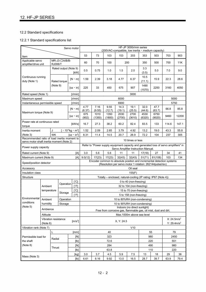
12 - 2
12. HF-JP SERIES
12.2 Standard specifications
12.2.1 Standard specifications list
Servo motor
Item
HF-JP 3000r/min series (200VAC-compatible, low inertia medium capacity)
53 73 103 153 203 353 503 703 903
Applicable servo amplifier/drive unit
MR-J3- A/B/B-RJ006/T 60 70 100 200 350 500 700 11K
Continuous running
duty (Note 1)
Rated output (Note 9)
[kW] 0.5 0.75 1.0 1.5 2.0
3.3
(3.5) 5.0 7.0 9.0
Rated torque
(Note 9)
[N m] 1.59 2.39 3.18 4.77 6.37 10.5
(11.1) 15.9 22.3 28.6
[oz in] 225 33 450 675 907 1490
(1570) 2250 3160 4050
Rated speed (Note 1) [r/min] 3000
Maximum speed [r/min] 6000 5000
Instantaneous permissible speed [r/min] 6900 5750
Maximum torque (Note 9) [N m]
4.77 (6.37)
7.16 (9.55)
9.55 (12.7)
14.3 (19.1)
19.1 (25.5)
32.0 (44.6)
47.7 (63.7) 66.8 85.8
[oz in] 675
(902) 1010
(1350) 1350
(1800) 2030
(2700) 2700
(3610) 4530
(6320) 6750
(9020) 9460 12200
Power rate at continuous rated
torque [kW/s] 16.7 27.3 38.2 60.2 82.4 83.5 133 114.6 147.1
Inertia moment
(Note 3)
J [ 10-4kg m2] 1.52 2.09 2.65 3.79 4.92 13.2 19.0 43.3 55.8
WK [oz in2] 8.31 11.4 14.5 20.7 26.9 72.2 104 237 305 Recommended ratio of load inertia moment to servo motor shaft inertia moment (Note 2) 10 times or less
Power supply capacity Refer to "Power supply equipment capacity and generated loss of servo amplifiers" in
Servo Amplifier Instruction Manual.
Rated current (Note 9) [A] 3.0 5.6 5.6 11 11 17(18) 27 34 41
Maximum current (Note 9) [A] 9.0(12) 17(23) 17(23) 32(43) 32(43) 51(71) 81(108) 103 134
Speed/position detector Encoder common to absolute position and incremental detection systems
(Resolution per servo motor 1 rotation: 262144pulse/rev)
Accessory Oil seal
Insulation class 155(F)
Structure Totally – enclosed, natural-cooling (IP rating: IP67 (Note 4))
Environmental
conditions
(Note 5)
Ambient
temperature
Operation [ ] 0 to 40 (non-freezing)
[ ] 32 to 104 (non-freezing)
Storage [ ] 15 to 70 (non-freezing)
[ ] 5 to 158 (non-freezing)
Ambient
humidity
Operation 10 to 80%RH (non-condensing)
Storage 10 to 90%RH (non-condensing)
Ambience Indoors (no direct sunlight)
Free from corrosive gas, flammable gas, oil mist, dust and dirt.
Altitude Max.1000m above sea level
Vibration resistance
(Note 6) [m/s2] X, Y: 24.5
X: 24.5m/s2
Y: 29.4m/s2
Vibration rank (Note 7) V10
Permissible load for
the shaft
(Note 8)
L [mm] 40 55 79
Radial [N] 323 980 2450
[lb] 72.6 220 551
Thrust [N] 284 490 980
[lb] 63.8 110 220
Mass (Note 3) [kg] 3.0 3.7 4.5 5.9 7.5 13 18 29 36
[lb] 6.61 8.16 9.92 13.0 16.5 28.7 39.7 63.9 79.4

12 - 3
12. HF-JP SERIES
Servo motor
Item
HF-JP 3000r/min series (400VAC-compatible, low inertia medium capacity)
534 734 1034 1534 2034 3534 5034 7034 9034
Applicable servo amplifier/drive unit
MR-J3- A4/B4/B4-RJ006/T4 60 100 200 350 500 700 11K
Continuous running
duty (Note 1)
Rated output
(Note 9) [kW] 0.5 0.75 1.0 1.5 2.0
3.3
(3.5) 5.0 7.0 9.0
Rated
torque
(Note 9)
[N m] 1.59 2.39 3.18 4.77 6.37 10.5
(11.1) 15.9 22.3 28.6
[oz in] 225 338 450 675 902 1490
(1570) 2250 3160 4050
Rated speed (Note 1) [r/min] 3000
Maximum speed [r/min] 6000 5000
Instantaneous permissible speed [r/min] 6900 5750
Maximum torque (Note 9)
[N m] 4.77
(6.37)
7.16
(9.55)
9.55
(12.7)
14.3
(19.1)
19.1
(25.5)
32.0
(44.6)
47.7
(63.7) 66.8 85.8
[oz in] 675
(902)
1010
(1350)
1350
(1800)
2030
(2700)
2700
(3610)
4530
(6320)
6750
(9020) 9460 12200
Power rate at continuous rated
torque [kW/s] 16.7 27.3 38.2 60.2 82.4 83.5 133 114.6 147.1
Inertia moment
(Note 3)
J [ 10-4kg m2] 1.52 2.09 2.65 3.79 4.92 13.2 19.0 43.3 55.8
WK [oz in2] 8.31 11.4 14.5 20.7 26.9 72.2 104 237 305 Recommended ratio of load inertia moment to servo motor shaft inertia moment (Note 2) 10 times or less
Power supply capacity Refer to "Power supply equipment capacity and generated loss of servo amplifiers" in
Servo Amplifier Instruction Manual.
Rated current (Note 9) [A] 1.5 2.8 2.8 5.4 5.4 8.3(8.8) 14 17 21
Maximum current (Note 9) [A] 4.5(6.0) 8.4(12) 8.4(12) 17(22) 17(22) 26(36) 41(54) 52 67
Speed/position detector Encoder common to absolute position and incremental detection systems
(Resolution per servo motor 1 rotation: 262144pulse/rev)
Accessory Oil seal
Insulation class 155(F)
Structure Totally – enclosed, natural-cooling (IP rating: IP67 (Note 4))
Environmental
conditions
(Note 5)
Ambient
temperature
Operation [ ] 0 to 40 (non-freezing)
[ ] 32 to 104 (non-freezing)
Storage [ ] 15 to 70 (non-freezing)
[ ] 5 to 158 (non-freezing)
Ambient
humidity
Operation 10 to 80%RH (non-condensing)
Storage 10 to 90%RH (non-condensing)
Ambience Indoors (no direct sunlight)
Free from corrosive gas, flammable gas, oil mist, dust and dirt.
Altitude Max.1000m above sea level
Vibration resistance
(Note 6) [m/s2] X, Y: 24.5
X: 24.5m/s2
Y: 29.4m/s2
Vibration rank (Note 7) V10
Permissible load for
the shaft
(Note 8)
L [mm] 40 55 79
Radial [N] 323 980 2450
[lb] 72.6 220 551
Thrust [N] 284 490 980
[lb] 63.8 110 220
Mass (Note 3) [kg] 3.0 3.7 4.5 5.9 7.5 13 18 29 36
[lb] 6.61 8.16 9.92 13.0 16.5 28.7 39.7 64 79

12 - 4
12. HF-JP SERIES
Servo motor
Item
HF-JP 1500r/min series
(200VAC-compatible,
low inertia large capacity)
HF-JP 1500r/min series
(400VAC-compatible,
low inertia large capacity)
11K1M 15K1M 11K1M4 15K1M4
Applicable servo
amplifier/drive unit
(Note 10) MR-J3-
A(4)-LR/
B(4)-LR/T(4)-LR
11K 15K 11K 15K
Continuous running
duty (Note 1)
Rated output [kW] 11 15 11 15
Rated
torque
[N m] 70 95.5 70 95.5
[oz in] 9910 13520 6610 13520
Rated speed (Note 1) [r/min] 1500
Maximum speed [r/min] 3000
Instantaneous permissible speed [r/min] 3450
Maximum torque [N m] 210 286 210 286
[oz in] 29700 40500 29700 40500
Power rate at continuous rated torque [kW/s] 223 290 223 290
Inertia moment
(Note 3)
J [ 10-4kg m2] 220 315 220 315
WK [oz in2] 1200 1720 1200 1720
Recommended ratio of load inertia moment to
servo motor shaft inertia moment (Note 2) 10 times or less
Power supply capacity Refer to "Power supply equipment capacity and generated loss of servo amplifiers"
in Servo Amplifier Instruction Manual.
Rated current [A] 61 76 31 38
Maximum current [A] 200 315 220 315
Speed/position detector Encoder common to absolute position and incremental detection systems
(Resolution per servo motor 1 rotation: 262144pulse/rev)
Accessory Oil seal
Insulation class 155(F)
Structure Totally - enclosed, natural-cooling (IP rating: IP67 (Note 4))
Environmental
conditions
(Note 5)
Ambient
temperature
Operation [ ] 0 to 40 (non-freezing)
[ ] 32 to 104 (non-freezing)
Storage [ ] 15 to 70 (non-freezing)
[ ] 5 to 158 (non-freezing)
Ambient
humidity
Operation 10 to 80%RH (non-condensing)
Storage 10 to 90%RH (non-condensing)
Ambience Indoors (no direct sunlight)
Free from corrosive gas, flammable gas, oil mist, dust and dirt.
Altitude Max.1000m above sea level
Vibration resistance
(Note 6) [m/s2] X, Y: 24.5
Vibration rank (Note 7) V10
Permissible load for
the shaft
(Note 8)
L [mm] 116
Radial [N] 2940
[lb] 661
Thrust [N] 980
[lb] 220
Mass (Note 3) [kg] 62 86 62 86
[lb] 137 190 137 190

12 - 5
12. HF-JP SERIES
Note 1. When the power supply voltage drops, the output and the rated speed cannot be guaranteed.
2. If the load inertia moment ratio exceeds the indicated value, please contact your local sales office.
3. Refer to the outline dimension drawing for the servo motor with an electromagnetic brake.
4. Except for the shaft-through portion.
5. In the environment where the servo motor is exposed to oil mist, oil and/or water, the servo motor of the standard specifications
may not be usable. Please contact your local sales office.
6. The vibration direction is as shown in the figure. The value is the one at the part that indicates the maximum value (normally the
opposite-to-load side bracket). When the servo motor stops, fretting is likely to occur at the bearing. Therefore, suppress the
vibration to about half of the permissible value.
YX
Servo motor
Vibration Vib
ratio
n a
mpl
itude
(b
oth
ampl
itude
s) [
m
]
Speed [r/min]0 1000 2000 3000 4000 5000 6000 7000
10
100
1000
7. V10 indicates that the amplitude of a single servo motor is 10 m or less. The following figure shows the servo motor installation
position for measurement and the measuring position.
Servo motor
Top
Bottom
Measuring position
8. For the symbols in the table, refer to the following diagram: Do not subject the shaft to load greater than this value.
The values in the table assume that the loads work singly.
LRadial load
Thrust load
L: Distance from flange mounting surface to load center
9. Values in ( ) are applicable when the maximum torque is increased to 400 . The maximum torque can be increased to 400
by combining with the following servo amplifiers.
MR-J3- A(4)-U1
MR-J3- B(4)-U1
MR-J3- T(4)-U1
10. Contact your local sales office for fully closed loop control compatible servo amplifier.
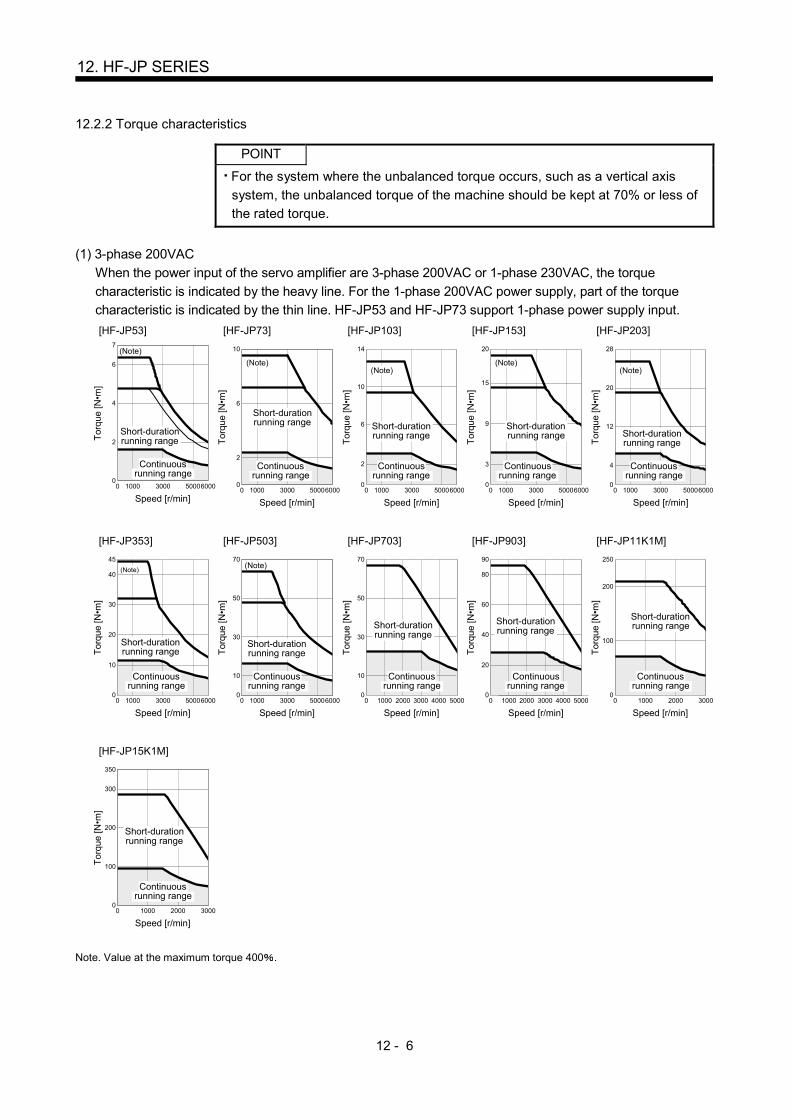
12 - 6
12. HF-JP SERIES
12.2.2 Torque characteristics
POINT
For the system where the unbalanced torque occurs, such as a vertical axis
system, the unbalanced torque of the machine should be kept at 70% or less of
the rated torque.
(1) 3-phase 200VAC
When the power input of the servo amplifier are 3-phase 200VAC or 1-phase 230VAC, the torque
characteristic is indicated by the heavy line. For the 1-phase 200VAC power supply, part of the torque
characteristic is indicated by the thin line. HF-JP53 and HF-JP73 support 1-phase power supply input.
[HF-JP53]
1000 3000 500060000
(Note)
Speed [r/min]
Continuousrunning range
Short-durationrunning rangeT
orqu
e [N
•m]
0
7
4
2
6
[HF-JP73]
1000 3000 500060000
(Note)
Speed [r/min]
Continuousrunning range
Short-durationrunning range
Tor
que
[N•m
]
0
6
10
2
[HF-JP103]
1000 3000 500060000
(Note)
Speed [r/min]
Continuousrunning range
Short-durationrunning range
Tor
que
[N•m
] 10
2
6
14
0
[HF-JP153]
1000 3000 500060000
(Note)
Speed [r/min]
Continuousrunning range
Short-durationrunning range
Tor
que
[N•m
]
9
20
3
15
0
[HF-JP203]
28
20
12
4
00 1000 3000 50006000
Tor
que
[N•m
]
(Note)
Short-durationrunning range
Continuousrunning range
Speed [r/min]
[HF-JP353]
1000 3000 500060000
(Note)
Speed [r/min]
Continuousrunning range
Short-durationrunning rangeT
orqu
e [N
•m]
0
45
30
20
10
40
[HF-JP503]
1000 3000 500060000
(Note)
Speed [r/min]
Continuousrunning range
Short-durationrunning rangeT
orqu
e [N
•m]
0
30
10
50
70
[HF-JP703]
1000 2000 3000 4000 500000
70
30
10
50
Speed [r/min]
Continuousrunning range
Short-durationrunning range
Tor
que
[N•m
]
[HF-JP903]
1000 2000 3000 4000 50000
Speed [r/min]
Continuousrunning range
Short-durationrunning range
Tor
que
[N•m
]
0
90
40
20
60
80
[HF-JP11K1M]
1000 2000 30000
Speed [r/min]
Continuousrunning range
Short-durationrunning range
Tor
que
[N•m
]
0
250
100
200
1000 2000 30000
[HF-JP15K1M]
Speed [r/min]
Continuousrunning range
Short-durationrunning range
Tor
que
[N•m
]
200
350
100
300
0
Note. Value at the maximum torque 400 .

12 - 7
12. HF-JP SERIES
(2) 3-phase 400VAC
When the power input of the servo amplifier are 3-phase 400VAC, the torque characteristic is indicated by
the heavy line. For the 3-phase 380VAC power supply, part of the torque characteristic is indicated by the
thin line.
[HF-JP534]
1000 3000 500060000
(Note)
Speed [r/min]
Continuousrunning range
Short-durationrunning rangeT
orqu
e [N
•m]
0
4
7
2
6
[HF-JP734]
1000 3000 500060000
(Note)
Speed [r/min]
Continuousrunning range
Short-durationrunning range
Tor
que
[N•m
]
0
6
10
2
[HF-JP1034]
1000 3000 500060000
(Note)
Speed [r/min]
Continuousrunning range
Short-durationrunning range
Tor
que
[N•m
]0
10
2
6
14
[HF-JP1534]
1000 3000 500060000
(Note)
Speed [r/min]
Continuousrunning range
Short-durationrunning range
Tor
que
[N•m
]
0
9
20
3
15
[HF-JP2034]
1000 3000 500060000
(Note)
Speed [r/min]
Continuousrunning range
Short-durationrunning rangeT
orqu
e [N
•m]
0
12
28
4
20
[HF-JP3534]
1000 3000 500060000
(Note)
Speed [r/min]
Continuousrunning range
Short-durationrunning rangeT
orqu
e [N
•m]
45
30
20
10
40
0
(Note)
[HF-JP5034]
1000 3000 500060000
Speed [r/min]
Continuousrunning range
Short-durationrunning rangeT
orqu
e [N
•m]
0
70
30
10
50
[HF-JP7034]
1000 2000 3000 4000 50000
Speed [r/min]
Continuousrunning range
Short-durationrunning range
Tor
que
[N•m
]
0
70
30
10
50
[HF-JP9034]
1000 2000 3000 4000 500000
90
20
60
40
80
Speed [r/min]
Continuousrunning range
Short-durationrunning range
Tor
que
[N•m
]
[HF-JP11K1M4]
1000 2000 30000
Speed [r/min]
Continuousrunning range
Short-durationrunning range
Tor
que
[N•m
]
0
200
250
100
1000 2000 30000
[HF-JP15K1M4]
Speed [r/min]
Continuousrunning range
Short-durationrunning range
Tor
que
[N•m
]
0
200
350
100
300
Note. Value at the maximum torque 400 .
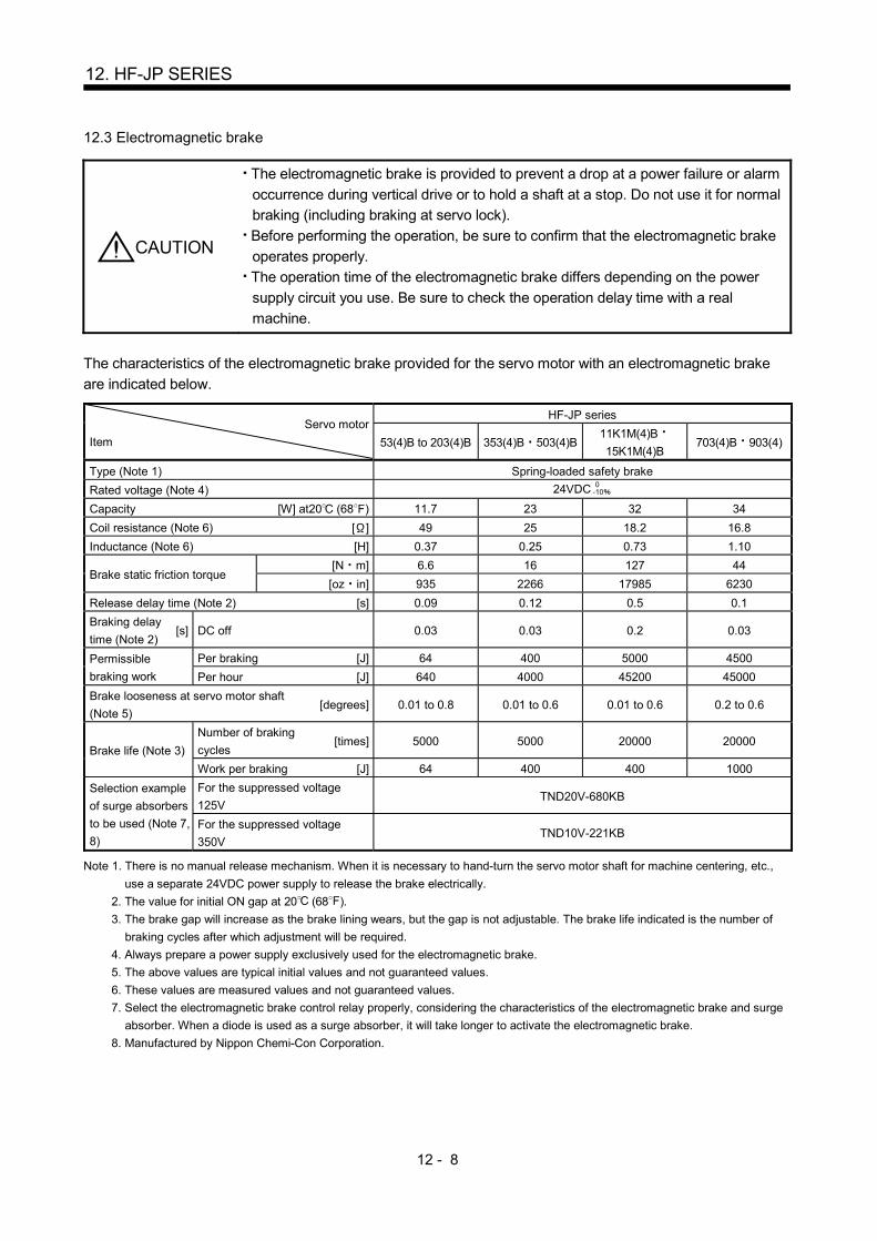
12 - 8
12. HF-JP SERIES
12.3 Electromagnetic brake
CAUTION
The electromagnetic brake is provided to prevent a drop at a power failure or alarm
occurrence during vertical drive or to hold a shaft at a stop. Do not use it for normal
braking (including braking at servo lock).
Before performing the operation, be sure to confirm that the electromagnetic brake
operates properly.
The operation time of the electromagnetic brake differs depending on the power
supply circuit you use. Be sure to check the operation delay time with a real
machine.
The characteristics of the electromagnetic brake provided for the servo motor with an electromagnetic brake
are indicated below.
Servo motor
Item
HF-JP series
53(4)B to 203(4)B 353(4)B 503(4)B 11K1M(4)B
15K1M(4)B 703(4)B 903(4)
Type (Note 1) Spring-loaded safety brake
Rated voltage (Note 4) 24VDC 0-10
Capacity [W] at20 (68 ) 11.7 23 32 34
Coil resistance (Note 6) [ ] 49 25 18.2 16.8
Inductance (Note 6) [H] 0.37 0.25 0.73 1.10
Brake static friction torque [N m] 6.6 16 127 44
[oz in] 935 2266 17985 6230
Release delay time (Note 2) [s] 0.09 0.12 0.5 0.1
Braking delay
time (Note 2) [s] DC off 0.03 0.03 0.2 0.03
Permissible
braking work
Per braking [J] 64 400 5000 4500
Per hour [J] 640 4000 45200 45000
Brake looseness at servo motor shaft
(Note 5) [degrees] 0.01 to 0.8 0.01 to 0.6 0.01 to 0.6 0.2 to 0.6
Brake life (Note 3)
Number of braking
cycles [times] 5000 5000 20000 20000
Work per braking [J] 64 400 400 1000
Selection example
of surge absorbers
to be used (Note 7,
8)
For the suppressed voltage
125V TND20V-680KB
For the suppressed voltage
350V TND10V-221KB
Note 1. There is no manual release mechanism. When it is necessary to hand-turn the servo motor shaft for machine centering, etc.,
use a separate 24VDC power supply to release the brake electrically.
2. The value for initial ON gap at 20 (68 ).
3. The brake gap will increase as the brake lining wears, but the gap is not adjustable. The brake life indicated is the number of
braking cycles after which adjustment will be required.
4. Always prepare a power supply exclusively used for the electromagnetic brake.
5. The above values are typical initial values and not guaranteed values.
6. These values are measured values and not guaranteed values.
7. Select the electromagnetic brake control relay properly, considering the characteristics of the electromagnetic brake and surge
absorber. When a diode is used as a surge absorber, it will take longer to activate the electromagnetic brake.
8. Manufactured by Nippon Chemi-Con Corporation.

12 - 9
12. HF-JP SERIES
12.4 Servo motors with special shafts
The servo motors with special shafts indicated by the symbol (K) in the table is available. K is the symbols
attached to the servo motor model names.
Servo motor Shaft shape
Keyway shaft (without key)
HF-JP53(4) to 15K1M(4) K
QL
A
A
QK
Q
R
W SU
r Y
Section A-A
[Unit: mm]
Servo motor Variable dimensions
S R Q W QK QL U r Y
HF-JP53(4)(B)K to
203(4)(B)K 16h6 40 30 5 0
0.030 25 2 3 0.10 2.5
M4 Depth
15
HF-JP353(4)(B)K
503(4)(B)K 28h6 55 50 8 0
0.036 36 5 4 0.20 4
M8 Depth
20
HF-JP703(4)(B)K
903(4)(B)K 35 0.010
0 79 75 00.03610 55 5 5 0.2
0 5 M8 Depth
20
HF-
JP11K1M(4)(B)K HF-JP15K1M(4)(B)K
55M6 116 110 16 00.040 90 5 6 0.2
0 8 M10 Depth
27
Keyway shaft (without key)
12.5 Wiring option
Connecter sets to use in power supply connector or brake connector are available as option.
For details of each connector set, cable and connector set to use in wiring to encoder, refer to the Servo
Amplifier Instruction Manual for using.
Make sure to use the following power supply connector set for conforming to the IEC/EN compliant.
Servo motor (Note) Power supply
connector set Brake connector set
HF-JP53 to 203 534 to 5034 MR-PWCNS4
MR-BKCNS1
(Straight type)
Configuration products
Straight plug : CM10-SP2S-L(D6)
Socket contact : CM10-#22SC(S2)(D8)-100
(DDK)
or
MR-BKCNS1A
(Angle type)
Configuration products
Angle plug : CM10-AP2S-L(D6)
Socket contact : CM10-#22SC(S2)(D8)-100
(DDK)
HF-JP353 503 MR-PWCNS5
HF-JP703(4) 903(4)
MR-PWCNS3
HF-JP11K1M(4) 15K1M(4)
MR-BKCN
(Straight type)
Configuration products
Plug : D/MS3106A10SL-4S(D190)
(DDK)
Cable clamp : YSO10-5 to 8
(Daiwa Dengyo)
Note. The configuration products for power supply connector set are as shown below.
MR-PWCNS4 (Plug: CE05-6A18-10SD-D-BSS Cable clamp: CE3057-10A-1-D)
MR-PWCNS5 (Plug: CE05-6A22-22SD-D-BSS Cable clamp: CE3057-12A-1-D)
MR-PWCNS3 (Plug: CE05-6A32-17SD-D-BSS Cable clamp: CE3057-20A-1-D)
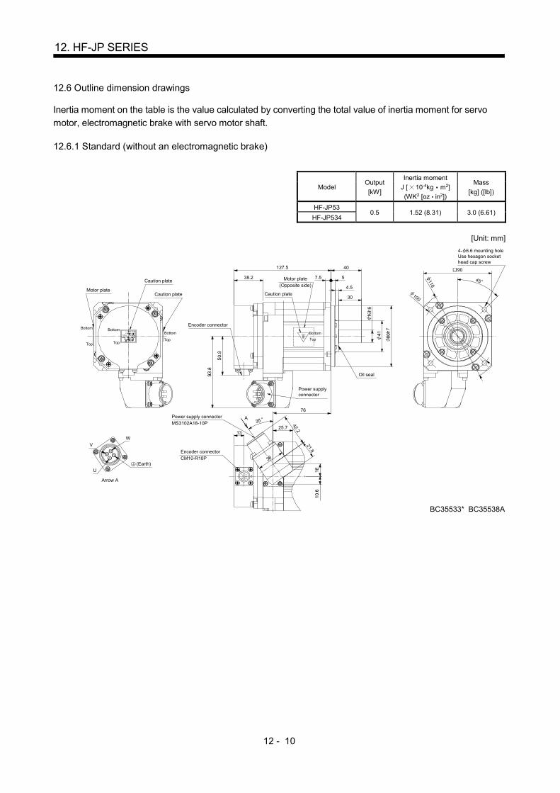
12 - 10
12. HF-JP SERIES
12.6 Outline dimension drawings
Inertia moment on the table is the value calculated by converting the total value of inertia moment for servo
motor, electromagnetic brake with servo motor shaft. 12.6.1 Standard (without an electromagnetic brake)
Model Output
[kW]
Inertia moment
J [ 10-4kg m2]
(WK2 [oz in2])
Mass
[kg] ([lb])
HF-JP53 0.5 1.52 (8.31) 3.0 (6.61)
HF-JP534
[Unit: mm]
Caution plate
Caution plateMotor plate
Bottom
Top
Bottom
Top
Bottom
Top
127.5 90
118
100
40
7.5 5
30
38.2
Oil seal
76
BC35533* BC35538A
13
45
4.5
A
W
V
U
36
42.2
21.8
25.7
(Earth)
Arrow A
Encoder connector
Encoder connectorCM10-R10P
Power supply connectorMS3102A18-10P
Power supplyconnector
35
4- 6.6 mounting holeUse hexagon sockethead cap screw
Caution plate
Motor plate(Opposite side)
Bottom
Top

12 - 11
12. HF-JP SERIES
Model Output
[kW]
Inertia moment
J [ 10-4kg m2]
(WK2 [oz in2])
Mass
[kg] ([lb])
HF-JP73 0.75 2.09 (11.4) 3.7 (8.16)
HF-JP734
[Unit: mm]
145.5
118
100
40
7.5 5
30
38.2
BC35534* BC35539A
94
13
4.5
A35
WV
U
36
42.2
21.8
25.7
Caution plate
Caution plate
Motor plate
Bottom
Top
Bottom
Top
Bottom
Top
90
Oil seal
45
(Earth)
Arrow A
Encoder connector
Encoder connectorCM10-R10P
Power supply connectorMS3102A18-10P
Power supply connector
Motor plate(Opposite side)
Caution plate
4- 6.6 mounting holeUse hexagon sockethead cap screw
Bottom
Top

12 - 12
12. HF-JP SERIES
Model Output
[kW]
Inertia moment
J [ 10-4kg m2]
(WK2 [oz in2])
Mass
[kg] ([lb])
HF-JP103 1.0 2.65 (14.5) 4.5 (9.92)
HF-JP1034
[Unit: mm]
163.5 40
7.5 5
30
38.2
112
BC35535* BC35540A
13
4.5
A35
WV
U
36
42.2
21.8
25.7
118
100
Caution plate
Caution plate
Motor plate
Bottom
Top
Bottom
Top
Bottom
Top
90
Oil seal
45
(Earth)
Arrow A
Encoder connector
Encoder connectorCM10-R10P
Power supply connectorMS3102A18-10P
Power supply connector
Motor plate(Opposite side)
Caution plate
4- 6.6 mounting holeUse hexagon sockethead cap screw
Bottom
Top

12 - 13
12. HF-JP SERIES
Model Output
[kW]
Inertia moment
J [ 10-4kg m2]
(WK2 [oz in2])
Mass
[kg] ([lb])
HF-JP153 1.5 3.79 (20.7) 5.9 (13.0)
HF-JP1534
[Unit: mm]
199.5
118
100
40
7.5 5
30
38.2
148
BC35536* BC35541A
13
45
4.5
A35
WV
U
36
42.2
21.8
25.7
Caution plate
Caution plate
Motor plate
Bottom
Top
Bottom
Top
Bottom
Top
90
Oil seal
(Earth)
Arrow A
Encoder connector
Encoder connectorCM10-R10P
Power supply connectorMS3102A18-10P
Power supply connector
Motor plate(Opposite side)
Caution plate
4- 6.6 mounting holeUse hexagon sockethead cap screw
Bottom
Top

12 - 14
12. HF-JP SERIES
Model Output
[kW]
Inertia moment
J [ 10-4kg m2]
(WK2 [oz in2])
Mass
[kg] ([lb])
HF-JP203 2.0 4.92 (26.9) 7.5 (16.5)
HF-JP2034
[Unit: mm]
235.5
118
100
40
7.5 5
30
38.2
184
BC35537* BC35542A
13
454.5
A35
WV
U
36
42.2
21.8
25.7
Oil seal
Caution plate
Caution plate
Motor plate
Bottom
Top
Bottom
Top
Bottom
Top
90
(Earth)
Arrow A
Encoderconnector
Encoder connectorCM10-R10P
Power supply connectorMS3102A18-10P
Power supply connector
Motor plate
(Opposite side)
Caution plate
4- 6.6 mounting holeUse hexagon sockethead cap screw
Bottom
Top
Model Output
[kW]
Inertia moment
J [ 10-4kg m2]
(WK2 [oz in2])
Mass
[kg] ([lb])
HF-JP353 3.5 13.2 (72.2) 13 (28.7)
[Unit: mm]
55
312
50
213
38.245
165
145
W
Key
Power supply connectorpin assignment
(View from front of the connector)
V
U
34
BC35548*
70.5
15.5
13
228
80
Oil seal
Caution plate
Caution plate
Motor plate
Bottom
Top
Bottom
Top
Bottom
Top
130
Earth
Encoder connector
CM10-R10P
Power supply connectorMS3102A22-22P
4- 9 mounting holeUse hexagon sockethead cap screw
Motor plate(Opposite side)Caution plate
Bottom
Top

12 - 15
12. HF-JP SERIES
Model Output
[kW]
Inertia moment
J [ 10-4kg m2]
(WK2 [oz in2])
Mass
[kg] ([lb])
HF-JP3534 3.5 13.2 (72.2) 13 (28.7)
[Unit: mm]
55
312
50
213
38.2
161
BC36562A
WV
U
45
165
145
42.221.8
36
13
A 3525.7
Oil seal
Caution plate
Caution plate
Motor plate
Bottom
Top
Bottom
Top
BottomTop
130
(Earth)
Arrow A
Encoder connector
Encoder connectorCM10-R10P
Power supply connectorMS3102A18-10P
Power supply connector
4- 9 mounting holeUse hexagon sockethead cap screw
Motor plate
(Opposite side)Caution plate
Bottom
Top
Model Output
[kW]
Inertia moment
J [ 10-4kg m2]
(WK2 [oz in2])
Mass
[kg] ([lb])
HF-JP503 5.0 19.0 (104) 18 (39.7)
[Unit: mm]
55
312
50
267
38.2
165
145
WV
U282
8034
13
70.5
15.5
BC35549*
Key
Power supply connectorpin assignment
(View from front of the connector)
Oil seal
Caution plate
Caution plate
Motor plate
Bottom
Top
Bottom
Top
Bottom
Top
130
Earth
Encoder connectorCM10-R10P
Power supply connector
MS3102A22-22P
4- 9 mounting holeUse hexagon sockethead cap screw
Motor plate(Opposite side)Caution plate
Bottom
Top

12 - 16
12. HF-JP SERIES
Model Output
[kW]
Inertia moment
J [ 10-4kg m2]
(WK2 [oz in2])
Mass
[kg] ([lb])
HF-JP5034 5.0 19.0 (104) 18 (39.7)
[Unit: mm]
55
312
50
267
38.2
215
BC36553A
WV
U
45
165
145
42.221.8
36
13
A 3525.7
Oil seal
Caution plate
Caution plate
Motor plate
Bottom
Top
Bottom
Top
Bottom
Top
130
(Earth)
Arrow A
Encoder connector
Encoder connectorCM10-R10P
Power supply connectorMS3102A18-10P
Power supply connector
4- 9 mounting holeUse hexagon sockethead cap screw
Motor plate(Opposite side)Caution plate
Bottom
Top
Model Output
[kW]
Inertia moment
J [ 10-4kg m2]
(WK2 [oz in2])
Mass
[kg] ([lb])
HF-JP703 7.0 43.3 (237) 29 (63.9)
HF-JP7034
[Unit: mm]
Bottom
Top
Motor plate
Caution plate
(Note)*1
(Note)*4
(Note)*2
(Note)*3
28.5
133.
5
Bottom
Top
Caution plate
Bottom
Top
Earth
WV
U Key
A
B
D
C
Power supply connectorpin assignment
(View from front of the connector)
263.5
38.5
50.9
163.
3 Oil seal
MS3102A32-17P
CM10-R10P
13
285.4
92.1
Bottom
Top
79
318
75
Motor plate(Opposite side)
Caution plate
Encoder connector
Power supply connector 44
102.3
BC37426*
176
45
4- 13.5 mounting holeUse hexagon sockethead cap screw
35
114.
3
200
230
0.0
10
0 0.0
25
Note. *1, *2, *3 and *4 are screw hole for eyebolt (M8).

12 - 17
12. HF-JP SERIES
Model Output
[kW]
Inertia moment
J [ 10-4kg m2]
(WK2 [oz in2])
Mass
[kg] ([lb])
HF-JP903 9.0 55.8 (305) 36 (79.4)
HF-JP9034
[Unit: mm]
Power supply connectorpin assignment
(View from front of the connector)35
114.
3
Caution plate
BC37427*
303.5
Oil seal
Bottom
Top
Motor plate
(Note)*1
(Note)*4
(Note)*2
(Note)*3
325.4
92.128.5
133.
5
Bottom
Top
Bottom
Top
38.550
.9
163.
3
MS3102A32-17P
13
Caution plateMotor plate
(Opposite side)
Caution plate
79
318
75
BottomTop
44
102.3
Encoder connector
CM10-R10P
Power supply connector
Earth
WV
U Key
A
B
D
C
230
45
200
4- 13.5 mounting holeUse hexagon sockethead cap screw
176
0.0
10
0 0.0
25
Note. *1, *2, *3 and *4 are screw hole for eyebolt (M8).

12 - 18
12. HF-JP SERIES
Model Output
[kW]
Inertia moment
J [ 10-4kg m2]
(WK2 [oz in2])
Mass
[kg] ([lb])
HF-JP11K1M 11 220 (1200) 62 (137)
HF-JP11K1M4
[Unit: mm]
W
V U
CB
DA
339.5 116
4
110
20
40
265.5
32
19.5
4
82
27
158.5
2-M8 screw
BC33586D
Power supply connector layoutMotor flange direction
(Note)*1 (Note)*2
(Note)*1, 2
(Note)*3, 4(Note)*4 (Note)*3
M10 screw
Oil seal
Caution plate
Caution plate
Motor plate
Bottom
Top
Bottom
Top
BottomTop
220
EarthEncoder connector
MS3102A20-29P
Power supply connectorMS3102A32-17P
4- 13.5 mounting holeUse hexagon sockethead cap screw
Motor plate(Opposite side)
Caution plate
BottomTop
Note. *1, *2, *3 and *4 are screw hole for eyebolt (M10).
Model Output
[kW]
Inertia moment
J [ 10-4kg m2]
(WK2 [oz in2])
Mass
[kg] ([lb])
HF-JP15K1M 15 315 (1720) 86 (190)
HF-JP15K1M4
[Unit: mm]
439.5 116
4
110
20
40
365.5
BC33590E
32 4
82
45
270
235
27
208.5
250
37.5
W
V U
CB
DA
19.5
2-M8 screw
Power supply connector layoutMotor flange direction
(Note)*1 (Note)*2
(Note)*1, 2
(Note)*3, 4(Note)*4 (Note)*3
M10 screw
Oil seal
Caution plate
Caution plate
Motor plate
Bottom
Top
Bottom
TopBottomTop
220
EarthEncoder connectorMS3102A20-29P
Power supply connector
MS3102A32-17P
4- 13.5 mounting holeUse hexagon sockethead cap screw
Motor plate(Opposite side)Caution plate
BottomTop
Note. *1, *2, *3 and *4 are screw hole for eyebolt (M10).

12 - 19
12. HF-JP SERIES
12.6.2 With an electromagnetic brake
Model Output
[kW]
Brake static friction
torque [N m]
([oz in])
Inertia moment
J [ 10-4kg m2]
(WK2 [oz in2])
Mass
[kg] ([lb])
HF-JP53B 0.5 6.6 (935) 2.02 (11.0) 4.4 (9.7)
HF-JP534B
[Unit: mm]
173
118
100
40
7.5 5
30
38
76
BC36548* BC35543A
13
454.5
A 35
W
V
U
36
42.2
21.8
66.525.7
Caution plate
Caution plateMotor plate
Bottom
Top
Bottom
Top
Bottom
Top
90
Oil seal
(Earth)
Arrow A
Encoder connector
Encoder connector
CM10-R10P
Power supply connector
MS3102A18-10P
Power supplyconnector
4- 6.6 mounting holeUse hexagon sockethead cap screw
Caution plate
Brake connector
CM10-R2P
Brake connector
Motor plate(Opposite side)
Bottom
Top
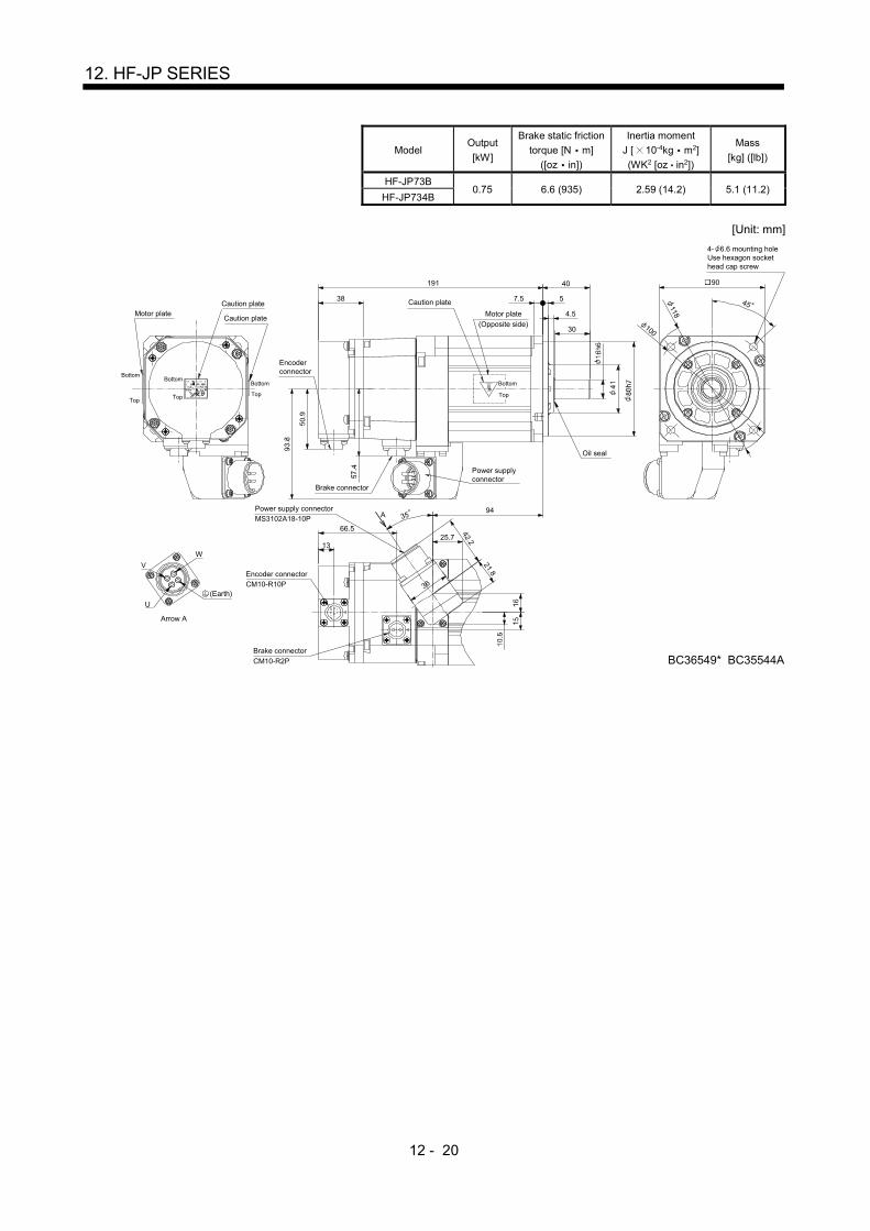
12 - 20
12. HF-JP SERIES
Model Output
[kW]
Brake static friction
torque [N m]
([oz in])
Inertia moment
J [ 10-4kg m2]
(WK2 [oz in2])
Mass
[kg] ([lb])
HF-JP73B 0.75 6.6 (935) 2.59 (14.2) 5.1 (11.2)
HF-JP734B
[Unit: mm]
191
118
100
40
7.5 5
30
38
94
BC36549* BC35544A
13
454.5
A 35
W
V
U
36
42.2
21.8
66.525.7
Caution plate
Caution plateMotor plate
Bottom
Top
Bottom
Top
Bottom
Top
90
Oil seal
(Earth)
Arrow A
Encoderconnector
Encoder connectorCM10-R10P
Power supply connectorMS3102A18-10P
Power supplyconnector
4- 6.6 mounting holeUse hexagon sockethead cap screw
Caution plate
Brake connector
CM10-R2P
Brake connector
Motor plate
(Opposite side)
Bottom
Top

12 - 21
12. HF-JP SERIES
Model Output
[kW]
Brake static friction
torque [N m]
([oz in])
Inertia moment
J [ 10-4kg m2]
(WK2 [oz in2])
Mass
[kg] ([lb])
HF-JP103B 1.0 6.6 (935) 3.15 (17.2) 5.9 (13.0)
HF-JP1034B
[Unit: mm]
209
118
100
40
7.5 5
30
38
BC36550* BC35545A
112
13
454.5
A35
W
V
U
36
42.2
21.8
66.525.7
Caution plate
Caution plateMotor plate
Bottom
Top
Bottom
Top
Bottom
Top
90
Oil seal
(Earth)
Arrow A
Encoderconnector
Encoder connectorCM10-R10P
Power supply connectorMS3102A18-10P
Power supply connector
4- 6.6 mounting holeUse hexagon sockethead cap screw
Caution plate
Brake connector
CM10-R2P
Brake connector
Motor plate
(Opposite side)
Bottom
Top

12 - 22
12. HF-JP SERIES
Model Output
[kW]
Brake static friction
torque [N m]
([oz in])
Inertia moment
J [ 10-4kg m2]
(WK2 [oz in2])
Mass
[kg] ([lb])
HF-JP153B 1.5 6.6 (935) 4.29 (23.5) 7.3 (16.1)
HF-JP1534B
[Unit: mm]
245
118
100
40
7.5 5
30
38
BC36551* BC35546A
148
13
454.5
A 35
WV
U
36
42.2
21.8
66.525.7
Caution plate
Caution plateMotor plate
Bottom
Top
Bottom
Top
Bottom
Top
90
Oil seal
(Earth)
Arrow A
Encoderconnector
Encoder connectorCM10-R10P
Power supply connector
MS3102A18-10P
Power supply connector
4- 6.6 mounting holeUse hexagon sockethead cap screw
Caution plate
Brake connector
CM10-R2P
Brake connector
Motor plate
(Opposite side)
Bottom
Top

12 - 23
12. HF-JP SERIES
Model Output
[kW]
Brake static friction
torque [N m]
([oz in])
Inertia moment
J [ 10-4kg m2]
(WK2 [oz in2])
Mass
[kg] ([lb])
HF-JP203B 2.0 6.6 (935) 5.42 (29.6) 8.9 (19.6)
HF-JP2034B
[Unit: mm]
281
118
100
40
7.5 5
30
38
BC36552* BC35547A
184
13
454.5
A 35
WV
U
36
42.2
21.8
66.525.7
Caution plate
Caution plateMotor plate
Bottom
Top
Bottom
Top
Bottom
Top
90
Oil seal
(Earth)
Arrow A
Encoderconnector
Encoder connector
CM10-R10P
Power supply connector
MS3102A18-10P
Power supply connector
4- 6.6 mounting holeUse hexagon sockethead cap screw
Caution plate
Brake connectorCM10-R2P
Brake connector
Motor plate
(Opposite side)
Bottom
Top
Model Output
[kW]
Brake static friction
torque [N m]
([oz in])
Inertia moment
J [ 10-4kg m2]
(WK2 [oz in2])
Mass
[kg] ([lb])
HF-JP353B 3.5 16.0 (2270) 15.4 (84.2) 15 (33.1)
[Unit: mm]
55
312
50
251.5
43.545
165
145
34
70.5
15.5
29WV
U
228
13
63
80
Brake
Brake connector layoutMotor flange direction BC36555*
Key
Power supply connectorpin assignment
(View from front of the connector)
Oil seal
Caution plate
Caution plate
Motor plate
Bottom
Top
Bottom
Top
Bottom
Top
130
Earth
Encoder connectorCM10-R10P
Power supply connectorMS3102A22-22P
4- 9 mounting holeUse hexagon sockethead cap screw
Motor plate(Opposite side)Caution plate
Brake connectorCM10-R2P
Bottom
Top

12 - 24
12. HF-JP SERIES
Model Output
[kW]
Brake static friction
torque [N m]
([oz in])
Inertia moment
J [ 10-4kg m2]
(WK2 [oz in2])
Mass
[kg] ([lb])
HF-JP3534B 3.5 16.0 (2270) 15.4 (84.2) 15 (33.1)
[Unit: mm]
55
312
50
BC35554A
251.5
43.5
13
63161
45
165
145
WV
U
A 35
36
42.221.8
25.7
Oil seal
Caution plate
Caution plate
Motor plate
Bottom
Top
Bottom
Top
BottomTop
130
(Earth)
Arrow A
Encoder connector
Encoder connectorCM10-R10P
Power supply connector
MS3102A18-10P
Power supply connector
4- 9 mounting holeUse hexagon sockethead cap screw
Caution plate
Brake connectorCM10-R2P
Brake connector
Motor plate(Opposite side)
Bottom
Top
Model Output
[kW]
Brake static friction
torque [N m]
([oz in])
Inertia moment
J [ 10-4kg m2]
(WK2 [oz in2])
Mass
[kg] ([lb])
HF-JP503B 5.0 16.0 (2270) 21.2 (116) 20 (44.1)
[Unit: mm]
55
312
50
305.5
43.545
165
145
WV
U
34
70.5
15.5
282
13
63
29
80
BC36556*
Bottom
Top
Brake
Brake connector layoutMotor flange direction
Key
Power supply connectorpin assignment
(View from front of the connector)
Oil seal
Caution plate
Caution plate
Motor plate
Bottom
Top
Bottom
Top
Bottom
Top
130
Earth
Encoder connectorCM10-R10P
Power supply connectorMS3102A22-22P
4- 9 mounting holeUse hexagon sockethead cap screw
Motor plate
(Opposite side)Caution plate
Brake connectorCM10-R2P
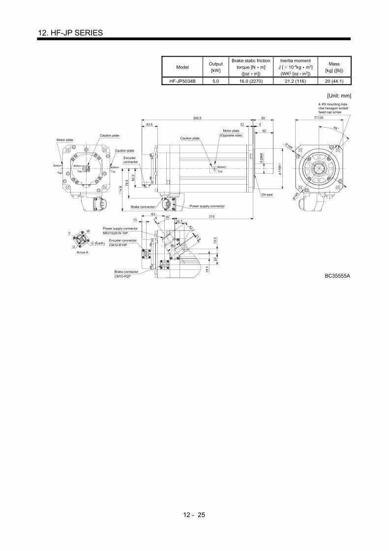
12 - 25
12. HF-JP SERIES
Model Output
[kW]
Brake static friction
torque [N m]
([oz in])
Inertia moment
J [ 10-4kg m2]
(WK2 [oz in2])
Mass
[kg] ([lb])
HF-JP5034B 5.0 16.0 (2270) 21.2 (116) 20 (44.1)
[Unit: mm]
55
312
50
BC35555A
305.5
43.5
13
63215
Brake connector
45
165
145
WV
U 36
42.221.8
A 3525.7
Oil seal
Caution plate
Caution plate
Motor plate
Bottom
Top
Bottom
Top
Bottom
Top
130
(Earth)
Arrow A
Encoderconnector
Encoder connector
CM10-R10P
Power supply connector
MS3102A18-10P
Power supply connector
4- 9 mounting holeUse hexagon sockethead cap screw
Motor plate
(Opposite side)Caution plate
Brake connector
CM10-R2P
Bottom
Top

12 - 26
12. HF-JP SERIES
Model Output
[kW]
Brake static friction torque [N m]
([oz in])
Inertia moment J [ 10-4kg m2] (WK2 [oz in2])
Mass
[kg] ([lb])
HF-JP703B 7.0 44 52.9 (289) 35 (77.2)
HF-JP7034B
[Unit: mm]
Bottom
Top
Motor plate
Caution plate
(Note)*1
(Note)*4
(Note)*2
(Note)*3
28.5
133.
5
44
BottomTop
Caution plate
Earth
WV
U
Power supply connectorpin assignment
(View from front of the connector)
Key
A
B
D
C
Brake connector layoutMotor flange direction
Bottom
Top
44
102.3Brake connector
MS3102A32-17P
79
318
75
313
45.5
50.9
96.9
163.
3
CM10-R2P
Oil seal
Power supply connector
Encoder connector
CM10-R10P
13
66.5
285.4
92.1
Bottom
Top
Motor plate
(Opposite side)
Caution plate
35
114.
3
BC37428*
Brake
4- 13.5 mounting holeUse hexagon sockethead cap screw
176
45
200
230
Main keyposition mark
0.0
10
0 0.0
25
Note. *1, *2, *3 and *4 are screw hole for eyebolt (M8).
Model Output
[kW]
Brake static friction torque [N m]
([oz in])
Inertia moment J [ 10-4kg m2] (WK2 [oz in2])
Mass
[kg] ([lb])
HF-JP903B 9.0 44 65.4 (358) 42 (92.6)
HF-JP9034B
[Unit: mm]
4- 13.5 mounting holeUse hexagon sockethead cap screw
45
200
230
BC37429*
Earth
WV
U
Power supply connectorpin assignment
(View from front of the connector)
Key
A
B
D
C
Brake connector layoutMotor flange direction
Main keyposition mark
Brake
79
318
75
353
45.5
50
.9
96
.9
16
3.3 Oil seal
Motor plate
(Opposite side)
Caution plate
Bottom
Top
Motor plate
Caution plate
13
66.5
(Note)*1
(Note)*4
(Note)*2
(Note)*3
325.4
92.128.5
13
3.5
44
Bottom
Top
Bottom
Top
Caution plate
Bottom
Top
44
102.3Brake connector
MS3102A32-17P
CM10-R2P
Power supply connector
Encoder connector
CM10-R10P
35
11
4.3
176
0.0
10
0 0.0
25
Note. *1, *2, *3 and *4 are screw hole for eyebolt (M8).

12 - 27
12. HF-JP SERIES
Model Output
[kW]
Brake static friction
torque [N m]
([oz in])
Inertia moment
J [ 10-4kg m2]
(WK2 [oz in2])
Mass
[kg] ([lb])
HF-JP11K1MB 11 126 (17800) 240 (1310) 74 (163)
HF-JP11K1M4B
[Unit: mm]
W
V U
BC33587D
CB
DA
412 116
4
110
20
40
265.5
32
27
M10 screw
4
82
45
270
235
250
37.5158.5
54
130
19.5
A
B
2-M8 screw
Brake
Brake connector layoutMotor flange direction
Oil seal
Caution plate
Caution plateMotor plate
Bottom
Top
Bottom
Top
Bottom
Top
220
Earth
Encoder connectorMS3102A20-29P
Power supply connectorMS3102A32-17P
4- 13.5 mounting holeUse hexagon sockethead cap screw
Motor plate
(Opposite side)
Caution plate
Brake connectorMS3102A10SL-4P
(Note)*1 (Note)*2
(Note)*1, 2
(Note)*3, 4(Note)*4 (Note)*3
BottomTop
Power supply connector layoutMotor flange direction
Note. *1, *2, *3 and *4 are screw hole for eyebolt (M10).
Model Output
[kW]
Brake static friction
torque [N m]
([oz in])
Inertia moment
J [ 10-4kg m2]
(WK2 [oz in2])
Mass
[kg] ([lb])
HF-JP15K1MB 15 126 (17800) 336 (1840) 97 (214)
HF-JP15K1M4B
[Unit: mm]
512 116
4
110
20
40
365.5
32
27
4
82
45
270
235
250
37.5208.5
54
19.5130
W
V U
C
B
D
A
A
B
BC33591E
M10 screw
2-M8screw
Brake
Brake connector layoutMotor flange direction
Oil seal
Caution plate
Caution plateMotor plate
Bottom
Top
BottomTop
Bottom
Top
220
Earth
Encoder connectorMS3102A20-29P
Power supply connector
MS3102A32-17P
4- 13.5 mounting holeUse hexagon sockethead cap screw
Motor plate(Opposite side)
Caution plate
Brake connector
MS3102A10SL-4P
(Note)*1 (Note)*2
(Note)*1, 2
(Note)*3, 4(Note)*4 (Note)*3
Power supply connector layoutMotor flange direction
BottomTop
Note. *1, *2, *3 and *4 are screw hole for eyebolt (M10).

12 - 28
12. HF-JP SERIES
12.7 Servo motor with oil seal
For the servo motor with oil seal, the oil seal prevents the entry of oil into the servo motor. Install the servo motor horizontally, and set the oil level in the gear box to be lower than the oil seal lip always.
GearShaft
Servo motor
Oil seal
Height above oil level h
Lip
Servo motor Height above oil level h [mm]
HF-JP53(4) 73(4)
103(4) 153(4) 203(4) 18
HF-JP353(4) 503(4) 20
HF-JP703(4) 903(4) 25
HF-JP11K1M(4) 15K1M(4)
40
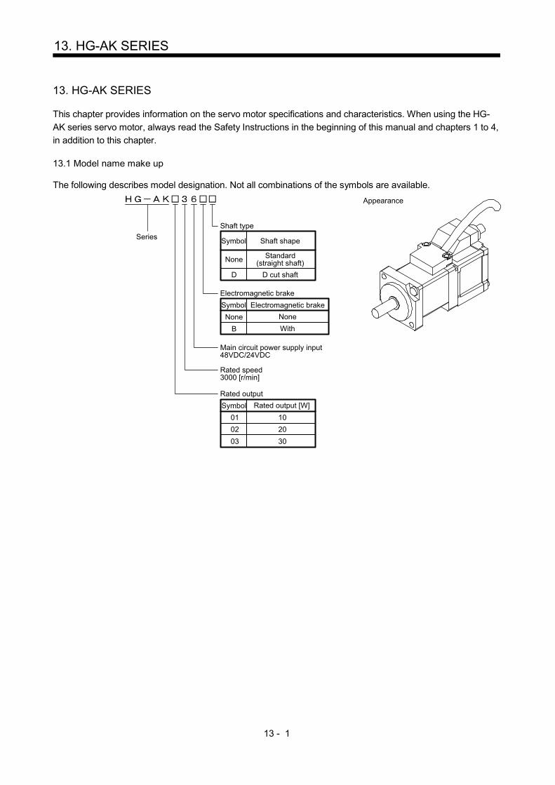
13 - 1
13. HG-AK SERIES
13. HG-AK SERIES
This chapter provides information on the servo motor specifications and characteristics. When using the HG-
AK series servo motor, always read the Safety Instructions in the beginning of this manual and chapters 1 to 4,
in addition to this chapter. 13.1 Model name make up
The following describes model designation. Not all combinations of the symbols are available.
Appearance
Shaft type
Symbol Shaft shape
None Standard(straight shaft)
Rated speed3000 [r/min]
None None
Electromagnetic brake
Symbol Electromagnetic brake
B With
01 10
Rated output
Symbol Rated output [W]
02 20
03 30
Series
Main circuit power supply input48VDC/24VDC
D D cut shaft
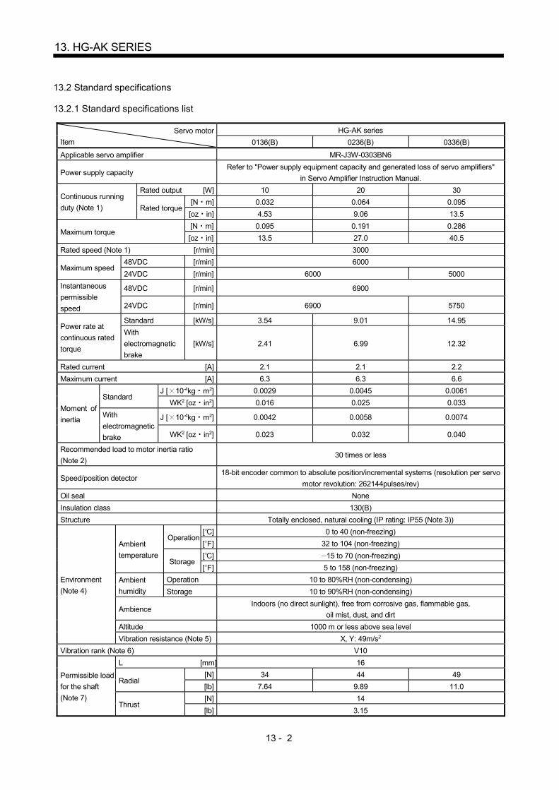
13 - 2
13. HG-AK SERIES
13.2 Standard specifications
13.2.1 Standard specifications list
Servo motor
Item
HG-AK series
0136(B) 0236(B) 0336(B)
Applicable servo amplifier MR-J3W-0303BN6
Power supply capacity Refer to "Power supply equipment capacity and generated loss of servo amplifiers"
in Servo Amplifier Instruction Manual.
Continuous running
duty (Note 1)
Rated output [W] 10 20 30
Rated torque [N m] 0.032 0.064 0.095
[oz in] 4.53 9.06 13.5
Maximum torque [N m] 0.095 0.191 0.286
[oz in] 13.5 27.0 40.5
Rated speed (Note 1) [r/min] 3000
Maximum speed 48VDC [r/min] 6000
24VDC [r/min] 6000 5000
Instantaneous
permissible
speed
48VDC [r/min] 6900
24VDC [r/min] 6900 5750
Power rate at
continuous rated
torque
Standard [kW/s] 3.54 9.01 14.95
With
electromagnetic
brake
[kW/s] 2.41 6.99 12.32
Rated current [A] 2.1 2.1 2.2
Maximum current [A] 6.3 6.3 6.6
Moment of
inertia
Standard J [ 10-4kg m2] 0.0029 0.0045 0.0061
WK2 [oz in2] 0.016 0.025 0.033
With
electromagnetic
brake
J [ 10-4kg m2] 0.0042 0.0058 0.0074
WK2 [oz in2] 0.023 0.032 0.040
Recommended load to motor inertia ratio
(Note 2) 30 times or less
Speed/position detector 18-bit encoder common to absolute position/incremental systems (resolution per servo
motor revolution: 262144pulses/rev)
Oil seal None
Insulation class 130(B)
Structure Totally enclosed, natural cooling (IP rating: IP55 (Note 3))
Environment
(Note 4)
Ambient
temperature
Operation [ ] 0 to 40 (non-freezing)
[ ] 32 to 104 (non-freezing)
Storage [ ] 15 to 70 (non-freezing)
[ ] 5 to 158 (non-freezing)
Ambient
humidity
Operation 10 to 80%RH (non-condensing)
Storage 10 to 90%RH (non-condensing)
Ambience Indoors (no direct sunlight), free from corrosive gas, flammable gas,
oil mist, dust, and dirt
Altitude 1000 m or less above sea level
Vibration resistance (Note 5) X, Y: 49m/s2
Vibration rank (Note 6) V10
Permissible load
for the shaft
(Note 7)
L [mm] 16
Radial [N] 34 44 49
[lb] 7.64 9.89 11.0
Thrust [N] 14
[lb] 3.15

13 - 3
13. HG-AK SERIES
Servo motor
Item
HG-AK series
0136(B) 0236(B) 0336(B)
Mass
Standard [kg] 0.12 0.14 0.16
[lb] 0.27 0.31 0.35
With
electromagnetic
brake
[kg] 0.22 0.24 0.26
[lb] 0.49 0.53 0.57
Note 1. When the power supply voltage drops, the output and the rated speed cannot be guaranteed.
2. If the load to motor inertia ratio exceeds the indicated value, contact your local sales office.
3. Except for the shaft-through, connector, and power cable outlet portion.
4. In the environment where the servo motor is exposed to oil mist, oil and/or water, the servo motor of the standard
specifications may not be usable. Please contact your local sales office for more details.
5. The vibration direction is as shown in the figure. The value is the one at the part that indicates the maximum value (normally
the opposite to load-side bracket). When the servo motor stops, fretting is likely to occur at the bearing. Therefore, suppress
the vibration to about half of the permissible value.
YX
Servo motor
Vibration Speed [r/min]
0 1000 2000 3000 4000 5000 6000 700010
100
1000
Vib
ratio
n am
plitu
de
(bot
h am
plitu
des)
[ m
]
6. V10 indicates that the amplitude of a single servo motor is 10 m or less. The following figure shows the servo motor mounting
position for measurement and the measuring position.
Servo motor
Top
Bottom
Measuring position
7. For the symbols in the table, refer to the following diagram: Do not subject the shaft to load greater than the value.
The value in the table assumes that the load is applied
independently.
LRadial load
Thrust load
L: Distance from flange mounting surface to load center

13 - 4
13. HG-AK SERIES
13.2.2 Torque characteristics
POINT
For the system where the unbalanced torque occurs, such as a vertical axis
system, the unbalanced torque of the machine should be kept at 70% or less of
the rated torque.
For the torque characteristics, MR-J3W03PWCBL5M-A-H or MR-
J3W03PWBRCBL5M-A-H was used for connecting servo amplifiers and servo
motors.
When the main circuit power supply input of the servo amplifier is 24VDC for HG-
AK0336, the maximum speed will be 5000r/min.
When the main power supply input of the servo amplifier is 48VDC, the torque characteristic is indicated by the
heavy line. For 24VDC, part of the torque characteristic is indicated by the thin line.
0
[HG-AK0136]
To
rqu
e [
N•m
]
10002000
30004000
50006000
Speed [r/min]
Continuousrunning range
Short-durationrunning range
0.100
0.075
0.050
0.025
0.000
0
[HG-AK0236]
Tor
que
[N•m
]
10002000
30004000
50006000
Speed [r/min]
Continuousrunning range
Short-durationrunning range
0.20
0.15
0.10
0.05
0.00
0
[HG-AK0336]
Tor
que
[N•m
]
10002000
30004000
50006000
Speed [r/min]
Continuousrunning range
Short-durationrunning range
0.4
0.3
0.2
0.1
0.0
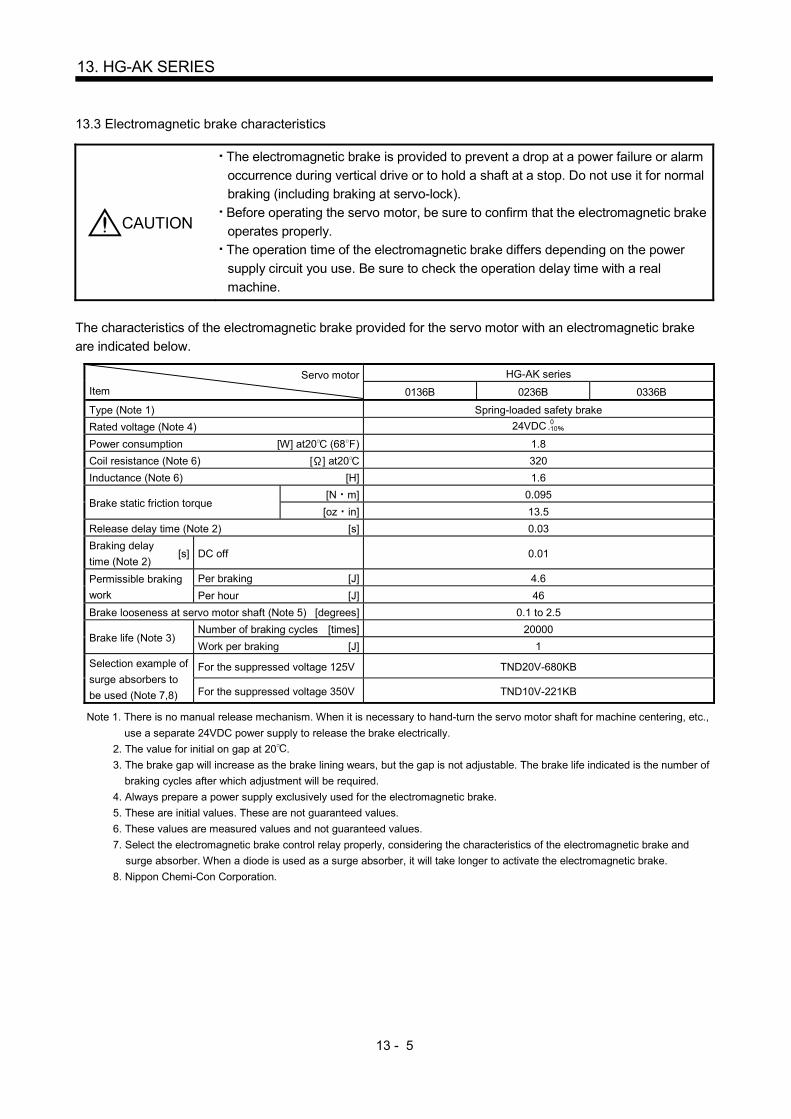
13 - 5
13. HG-AK SERIES
13.3 Electromagnetic brake characteristics
CAUTION
The electromagnetic brake is provided to prevent a drop at a power failure or alarm
occurrence during vertical drive or to hold a shaft at a stop. Do not use it for normal
braking (including braking at servo-lock).
Before operating the servo motor, be sure to confirm that the electromagnetic brake
operates properly.
The operation time of the electromagnetic brake differs depending on the power
supply circuit you use. Be sure to check the operation delay time with a real
machine.
The characteristics of the electromagnetic brake provided for the servo motor with an electromagnetic brake
are indicated below.
Servo motor
Item
HG-AK series
0136B 0236B 0336B
Type (Note 1) Spring-loaded safety brake
Rated voltage (Note 4) 24VDC 0-10
Power consumption [W] at20 (68 ) 1.8
Coil resistance (Note 6) [ ] at20 320
Inductance (Note 6) [H] 1.6
Brake static friction torque [N m] 0.095
[oz in] 13.5
Release delay time (Note 2) [s] 0.03
Braking delay
time (Note 2) [s] DC off 0.01
Permissible braking
work
Per braking [J] 4.6
Per hour [J] 46
Brake looseness at servo motor shaft (Note 5) [degrees] 0.1 to 2.5
Brake life (Note 3) Number of braking cycles [times] 20000
Work per braking [J] 1
Selection example of
surge absorbers to
be used (Note 7,8)
For the suppressed voltage 125V TND20V-680KB
For the suppressed voltage 350V TND10V-221KB
Note 1. There is no manual release mechanism. When it is necessary to hand-turn the servo motor shaft for machine centering, etc.,
use a separate 24VDC power supply to release the brake electrically.
2. The value for initial on gap at 20 .
3. The brake gap will increase as the brake lining wears, but the gap is not adjustable. The brake life indicated is the number of
braking cycles after which adjustment will be required.
4. Always prepare a power supply exclusively used for the electromagnetic brake.
5. These are initial values. These are not guaranteed values.
6. These values are measured values and not guaranteed values.
7. Select the electromagnetic brake control relay properly, considering the characteristics of the electromagnetic brake and
surge absorber. When a diode is used as a surge absorber, it will take longer to activate the electromagnetic brake.
8. Nippon Chemi-Con Corporation.

13 - 6
13. HG-AK SERIES
13.4 Servo motors with special shafts
The servo motors with special shafts indicated by the symbol(D) in the table is available. "D" is the symbol
attached to the servo motor model names.
Servo motor Shaft shape
D cut shaft
HG-AK (B) D
[Unit: mm]
16
13
10 0.5
5h6
13.5 Wiring option
Connector sets to use in power supply connector or brake connector are available as option. For details of
each cable, cable and connector set to use in wiring to encoder, refer to the Servo Amplifier Instruction Manual
for using. Make sure to use the following power supply cable for conforming to the IEC/EN Standard compliant.
Servo motor Servo motor power cable
HG-AK series MR-J3W03PWCBL M-A-H
MR-J3W03PWBRCBL M-A-H 13.6 Dimensions
The dimensions without tolerances are reference dimensions.
Inertia moment on the table is the value calculated by converting the total value of inertia moment for servo
motor, electromagnetic brake and decelerator with servo motor shaft.
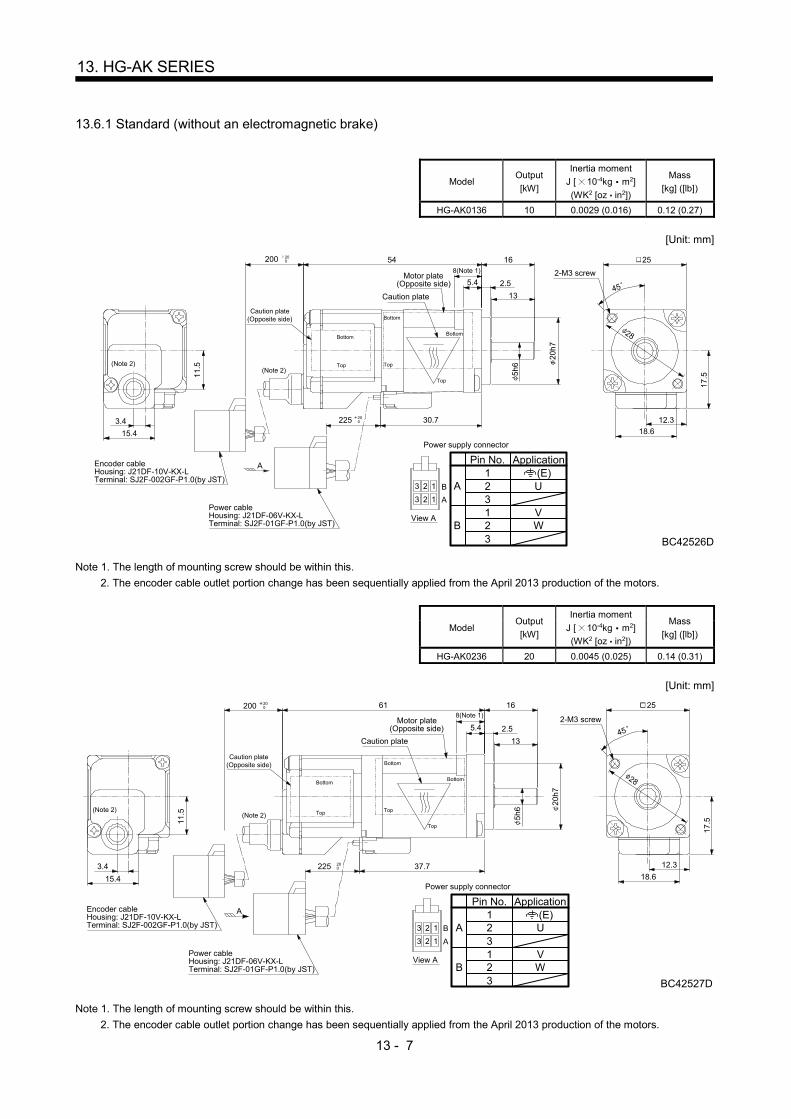
13 - 7
13. HG-AK SERIES
13.6.1 Standard (without an electromagnetic brake)
Model Output
[kW]
Inertia moment
J [ 10-4kg m2]
(WK2 [oz in2])
Mass
[kg] ([lb])
HG-AK0136 10 0.0029 (0.016) 0.12 (0.27)
[Unit: mm]
Encoder cableHousing: J21DF-10V-KX-LTerminal: SJ2F-002GF-P1.0(by JST)
Power cableHousing: J21DF-06V-KX-LTerminal: SJ2F-01GF-P1.0(by JST)
123 B
123 A
Power supply connector
16
13
54
5.4 2.5
20
h7
30.7
200
225 200
200 25
28
17
.5
12.3
18.615.4
11
.5
3.4
Bottom
Top
Caution plate(Opposite side)
8(Note 1)
Bottom
Top
Bottom
Top
A
45
2-M3 screw
5h
6View A
Motor plate(Opposite side)
Caution plate
Pin No.
13
12
32
A
B
Application
WV
U(E)
(Note 2)(Note 2)
BC42526D
Note 1. The length of mounting screw should be within this.
2. The encoder cable outlet portion change has been sequentially applied from the April 2013 production of the motors.
Model Output
[kW]
Inertia moment
J [ 10-4kg m2]
(WK2 [oz in2])
Mass
[kg] ([lb])
HG-AK0236 20 0.0045 (0.025) 0.14 (0.31)
[Unit: mm]
Encoder cableHousing: J21DF-10V-KX-LTerminal: SJ2F-002GF-P1.0(by JST)
Power cableHousing: J21DF-06V-KX-LTerminal: SJ2F-01GF-P1.0(by JST)
16
13
61
5.4 2.5
20
h7
37.7
200 200
200225
25
28
17
.5
12.3
18.615.4
11
.5
3.4
Bottom
Top
Caution plate(Opposite side)
8(Note 1)
Bottom
Top
Bottom
Top
A
45
2-M3 screw
5h
6
Motor plate(Opposite side)
Caution plate
123 B
123 A
Power supply connector
View A
Pin No.
13
12
32
A
B
Application
WV
U(E)
BC42527D
(Note 2)(Note 2)
Note 1. The length of mounting screw should be within this.
2. The encoder cable outlet portion change has been sequentially applied from the April 2013 production of the motors.

13 - 8
13. HG-AK SERIES
Model Output
[kW]
Inertia moment
J [ 10-4kg m2]
(WK2 [oz in2])
Mass
[kg] ([lb])
HG-AK0336 30 0.0061 (0.033) 0.16 (0.35)
[Unit: mm]
Encoder cableHousing: J21DF-10V-KX-LTerminal: SJ2F-002GF-P1.0(by JST)
Power cableHousing: J21DF-06V-KX-LTerminal: SJ2F-01GF-P1.0(by JST)
16
13
68
5.4 2.5
20
h7
44.7
200 200
200225
25
28
17
.5
12.3
18.615.4
11
.5
3.4
Bottom
Top
Caution plate(Opposite side)
8(Note 1)
Bottom
Top
Bottom
Top
A
45
2-M3 screw
5h
6
Motor plate(Opposite side)Caution plate
123 B
123 A
Power supply connector
View A
Pin No.
13
12
32
A
B
Application
WV
U(E)
BC42528D
(Note 2)(Note 2)
Note 1. The length of mounting screw should be within this.
2. The encoder cable outlet portion change has been sequentially applied from the April 2013 production of the motors.
13.6.2 With an electromagnetic brake
Model Output
[kW]
Brake static friction
torque
[N m] ([oz in])
Moment of inertia J
[ 10-4kg m2]
(WK2 [oz in2])
Mass
[kg] ([lb])
HG-AK0136B 10 0.095 (13.5) 0.0042 (0.023) 0.22 (0.49)
[Unit: mm]
Encoder cableHousing: J21DF-10V-KX-LTerminal: SJ2F-002GF-P1.0(by JST)
Power cableHousing: J21DF-06V-KX-LTerminal: SJ2F-01GF-P1.0(by JST)
200 200
200245
251
7.5
24
15.4
11
.5
3.4
A
45
2-M3 screw
Motor plate(Opposite side)
Caution plate
28
5h
6
Bottom
Top
Top
Top
Bottom
Bottom
16
13
5.4 2.5
20
h7
42.7
8(Note 1)
86
Caution plate(Opposite side)
123 B
123 A
Power supply connector
View A
Pin No.
13
12
32
A
B
Application
W
B1
B2
V
U(E)
BC42542D
(Note 2)(Note 2)
Note 1. The length of mounting screw should be within this.
2. The encoder cable outlet portion change has been sequentially applied from the April 2013 production of the motors.

13 - 9
13. HG-AK SERIES
Model Output
[kW]
Brake static friction
torque
[N m] ([oz in])
Moment of inertia J
[ 10-4kg m2]
(WK2 [oz in2])
Mass
[kg] ([lb])
HG-AK0236B 20 0.095 (13.5) 0.0058 (0.032) 0.24 (0.53)
[Unit: mm]
Encoder cableHousing: J21DF-10V-KX-LTerminal: SJ2F-002GF-P1.0(by JST)
Power cableHousing: J21DF-06V-KX-LTerminal: SJ2F-01GF-P1.0(by JST)
200 200
200245
25
17
.5
24
15.4
11
.5
3.4
A
45
2-M3 screw
Motor plate(Opposite side)
Caution plate
28
5h
6
Bottom
Top
Top
Top
Bottom
Bottom
16
13
5.4 2.5
20
h7
49.7
8(Note 1)
93
Caution plate(Opposite side)
123 B
123 A
Power supply connector
View A
Pin No.
13
12
32
A
B
Application
W
B1
B2
V
U(E)
BC42543D
(Note 2)(Note 2)
Note 1. The length of mounting screw should be within this.
2. The encoder cable outlet portion change has been sequentially applied from the April 2013 production of the motors.
Model Output
[kW]
Brake static friction
torque
[N m] ([oz in])
Moment of inertia J
[ 10-4kg m2]
(WK2 [oz in2])
Mass
[kg] ([lb])
HG-AK0336B 30 0.095 (13.5) 0.0074 (0.040) 0.26 (0.57)
[Unit: mm]
Encoder cableHousing: J21DF-10V-KX-LTerminal: SJ2F-002GF-P1.0(by JST)
Power cableHousing: J21DF-06V-KX-LTerminal: SJ2F-01GF-P1.0(by JST)
200 200
200245
25
17
.5
24
15.4
11
.5
3.4
A
45
2-M3 screw
Motor plate(Opposite side)
Caution plate
28
5h
6
Bottom
Top
Top
Top
Bottom
Bottom
16
13
5.4 2.5
20
h7
56.7
8(Note 1)100
Caution plate(Opposite side)
123 B
123 A
Power supply connector
View A
Pin No.
13
12
32
A
B
Application
W
B1
B2
V
U(E)
BC42544D
(Note 2)(Note 2)
Note 1. The length of mounting screw should be within this.
2. The encoder cable outlet portion change has been sequentially applied from the April 2013 production of the motors.

13 - 10
13. HG-AK SERIES
MEMO
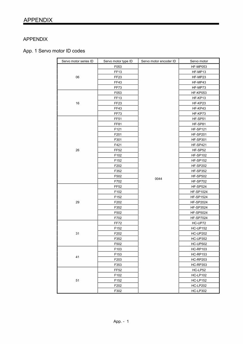
App. - 1
APPENDIX
APPENDIX
App. 1 Servo motor ID codes
Servo motor series ID Servo motor type ID Servo motor encoder ID Servo motor
F053 HF-MP053 FF13 HF-MP13
06 FF23 HF-MP23 FF43 HF-MP43 FF73 HF-MP73 F053 HF-KP053 FF13 HF-KP13
16 FF23 HF-KP23 FF43 HF-KP43 FF73 HF-KP73 FF51 HF-SP51 FF81 HF-SP81 F121 HF-SP121 F201 HF-SP201 F301 HF-SP301 F421 HF-SP421
26 FF52 HF-SP52 F102 HF-SP102 F152 HF-SP152 F202 HF-SP202 F352 HF-SP352 F502
0044 HF-SP502
F702 HF-SP702 FF52 HF-SP524 F102 HF-SP1024 F152 HF-SP1524
29 F202 HF-SP2024 F352 HF-SP3524 F502 HF-SP5024 F702 HF-SP7024 FF72 HC-UP72 F152 HC-UP152
31 F202 HC-UP202 F352 HC-UP352 F502 HC-UP502 F103 HC-RP103
41 F153 HC-RP153 F203 HC-RP203
F353 HC-RP353 FF52 HC-LP52 F102 HC-LP102
51 F152 HC-LP152 F202 HC-LP202 F302 HC-LP302
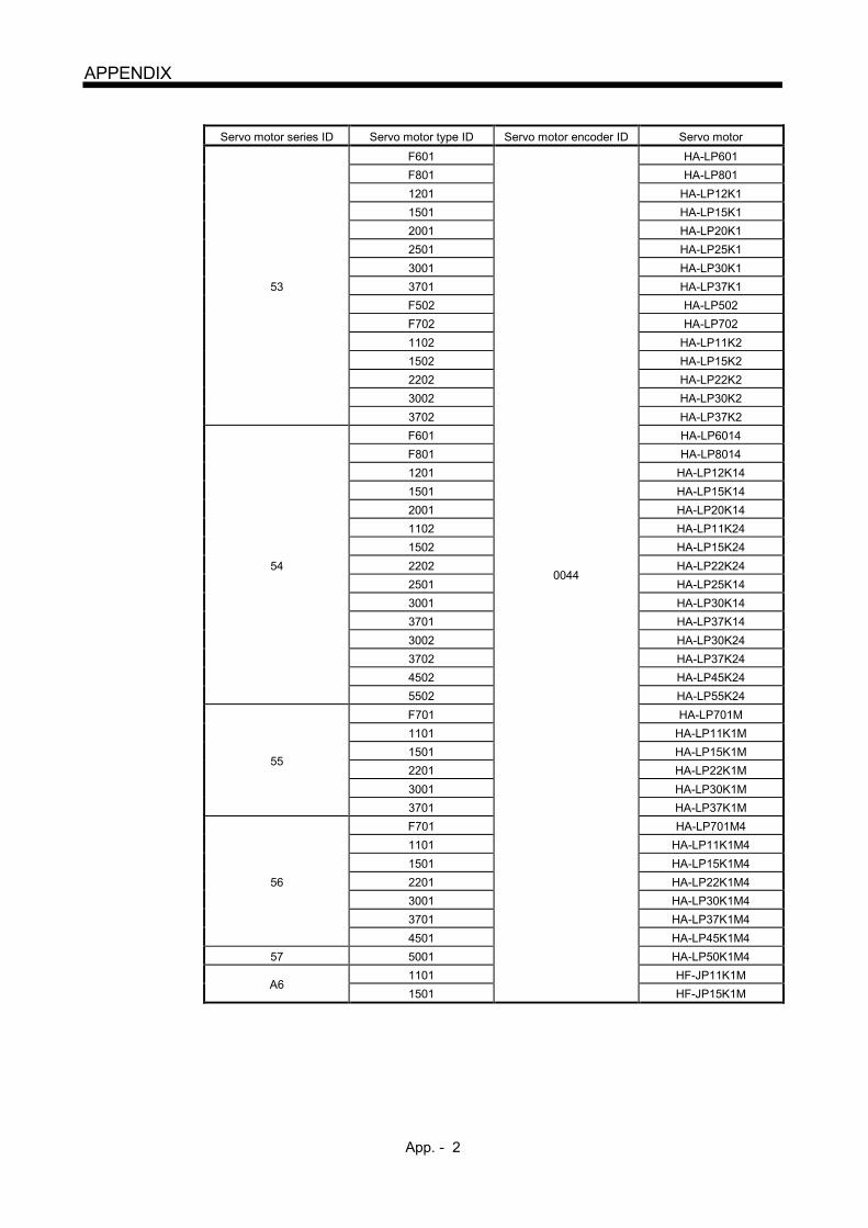
App. - 2
APPENDIX
Servo motor series ID Servo motor type ID Servo motor encoder ID Servo motor
F601 HA-LP601 F801 HA-LP801 1201 HA-LP12K1 1501 HA-LP15K1 2001 HA-LP20K1 2501 HA-LP25K1 3001 HA-LP30K1
53 3701 HA-LP37K1 F502 HA-LP502 F702 HA-LP702 1102 HA-LP11K2 1502 HA-LP15K2 2202 HA-LP22K2 3002 HA-LP30K2 3702 HA-LP37K2 F601 HA-LP6014 F801 HA-LP8014 1201 HA-LP12K14 1501 HA-LP15K14 2001 HA-LP20K14 1102 HA-LP11K24 1502 HA-LP15K24
54 2202 0044
HA-LP22K24 2501 HA-LP25K14 3001 HA-LP30K14 3701 HA-LP37K14 3002 HA-LP30K24 3702 HA-LP37K24 4502 HA-LP45K24 5502 HA-LP55K24 F701 HA-LP701M 1101 HA-LP11K1M
55 1501 HA-LP15K1M 2201 HA-LP22K1M
3001 HA-LP30K1M 3701 HA-LP37K1M F701 HA-LP701M4 1101 HA-LP11K1M4 1501 HA-LP15K1M4
56 2201 HA-LP22K1M4 3001 HA-LP30K1M4 3701 HA-LP37K1M4 4501 HA-LP45K1M4
57 5001 HA-LP50K1M4
A6 1101 HF-JP11K1M 1501 HF-JP15K1M

App. - 3
APPENDIX
Servo motor series ID Servo motor type ID Servo motor encoder ID Servo motor
FF53 HF-JP53 FF73 HF-JP73 F103 HF-JP103 F153 HF-JP153
A7 F203 HF-JP203 F353 HF-JP353 F503 HF-JP503 F703 HF-JP703 F903 HF-JP903
A8 1101 HF-JP11K1M4 1501 HF-JP15K1M4
FF53 0044 HF-JP534 FF73 HF-JP734 F103 HF-JP1034 F153 HF-JP1534
A9 F203 HF-JP2034 F353 HF-JP3534 F503 HF-JP5034 F703 HF-JP7034 F903 HF-JP9034 F013 HG-AK0136
0D F023 HG-AK0236 F033 HG-AK0336
App. 2 Compliance with the CE marking
App. 2.1 What is CE marking?
The CE marking is mandatory and must be affixed to specific products placed on the European Union. When a product conforms to the requirements, the CE marking must be affixed to the product. The CE marking also applies to machines and equipment incorporating servos. A manual is available in different languages. For details, contact your local sales office. (1) EMC directive
The EMC directive applies to the servo motor alone. Therefore servo motor is designed to comply with the EMC directive. The EMC directive also applies to machines and equipment incorporating servo motors. HF-KP, HF-MP, HF-SP, HA-LP, HC-RP, HC-UP, HC-LP, HF-JP and HG-AK series comply with EN61800-3 Category 3. They are not intended to be used on a low-voltage public network which supplies domestic premises; radio frequency interference is expected if it is used on such a network. The installer shall provide a guide for installation and use, including recommended mitigation devices.
(2) Low voltage directive
The low voltage directive also applies to the servo motor alone. The servo motor is designed to comply with the low voltage directive.
(3) Machinery directive
The servo motor as a single unit does not comply with the Machinery directive due to correspondence with article1 2. (k). However, machines and equipment incorporating servo motors will be complied. Please check your machines and equipment as a whole if they are complied.
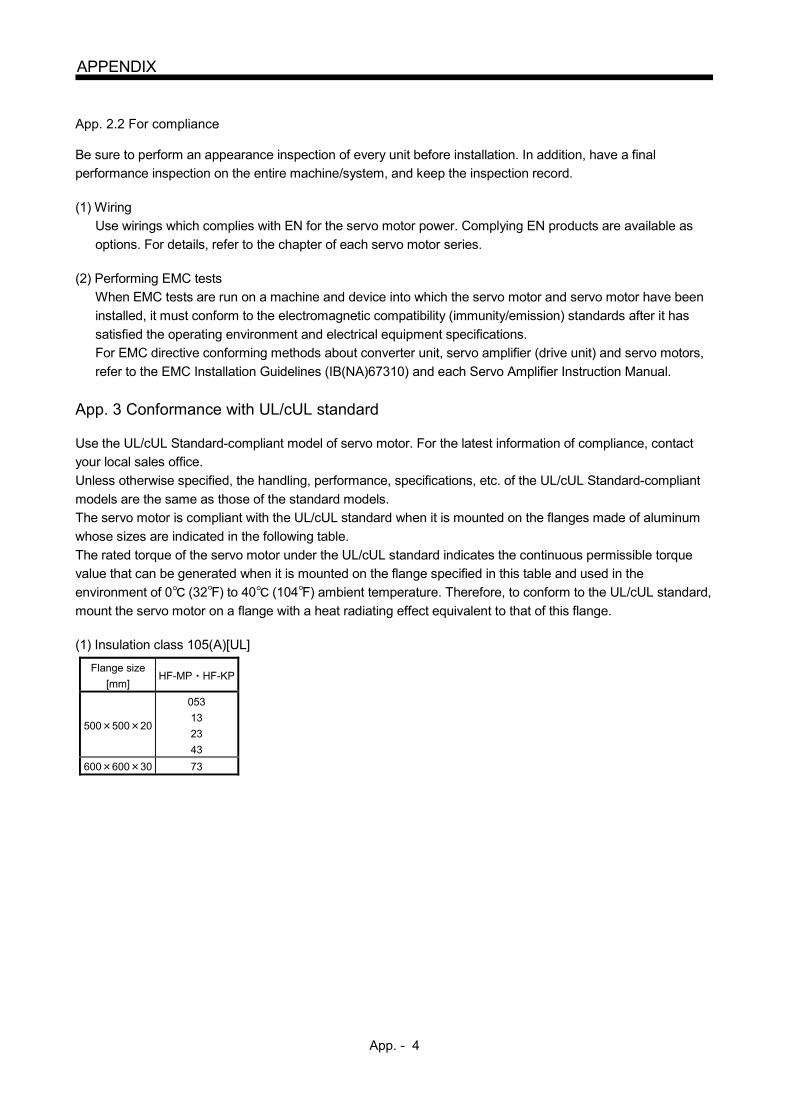
App. - 4
APPENDIX
App. 2.2 For compliance
Be sure to perform an appearance inspection of every unit before installation. In addition, have a final performance inspection on the entire machine/system, and keep the inspection record. (1) Wiring
Use wirings which complies with EN for the servo motor power. Complying EN products are available as options. For details, refer to the chapter of each servo motor series.
(2) Performing EMC tests
When EMC tests are run on a machine and device into which the servo motor and servo motor have been installed, it must conform to the electromagnetic compatibility (immunity/emission) standards after it has satisfied the operating environment and electrical equipment specifications. For EMC directive conforming methods about converter unit, servo amplifier (drive unit) and servo motors, refer to the EMC Installation Guidelines (IB(NA)67310) and each Servo Amplifier Instruction Manual.
App. 3 Conformance with UL/cUL standard
Use the UL/cUL Standard-compliant model of servo motor. For the latest information of compliance, contact your local sales office. Unless otherwise specified, the handling, performance, specifications, etc. of the UL/cUL Standard-compliant models are the same as those of the standard models. The servo motor is compliant with the UL/cUL standard when it is mounted on the flanges made of aluminum whose sizes are indicated in the following table. The rated torque of the servo motor under the UL/cUL standard indicates the continuous permissible torque value that can be generated when it is mounted on the flange specified in this table and used in the environment of 0 (32 ) to 40 (104 ) ambient temperature. Therefore, to conform to the UL/cUL standard, mount the servo motor on a flange with a heat radiating effect equivalent to that of this flange. (1) Insulation class 105(A)[UL]
Flange size [mm]
HF-MP HF-KP
500 500 20
053 13 23 43
600 600 30 73

App. - 5
APPENDIX
(2) Insulation class 130(B) and 155(F)
Flange size [mm]
Servo motor HF-MP
HF-KP [CE, TÜV]
HF-SP HC-RP HC-UP HC-LP HA-LP HF-JP HG-AK
150 150 3 0136 to 0336
250 250 6 053 13 23
250 250 12 43 51 81
52(4) to 152(4) 103 to 203 52 to 152 53(4) to 203(4)
300 300 12 73
300 300 20 121 201 202(4) to 352(4) 202 302
550 550 30 353 503 72 152 353(4) 503(4)
650 650 35 301 421
502(4) 702(4) 202 to 502
601(4) to 12K1(4) 701M(4) to 15K1M(4)
502 to 22K2 11K24 to 22K24
703(4) 903(4) 11K1M(4) 15K1M4(4)
950 950 35
15K1(4) to 37K1(4)
22K1M to 37K1M
22K1M4 to 50K1M4
30K2 37K2 30K24 to 55K24

REVISIONS
*The manual number is given on the bottom left of the back cover.
Print Data *Manual Number Revision
Oct. 2003 SH(NA)030041ENG-A First edition
Nov. 2004 SH(NA)030041ENG-B Safety Instructions: Addition of the HF-SP to the environment condition table
Section 1.1: Addition of the HF-SP to the table
Deletion of the HA-MH HA-ME from the table
Note description change
Section 1.2 (2): Moved to Section 6.1
Section 1.3: Change
Section 1.4: CAUTION change
Figure change
Section 1.5: Insertion of item "Servo motor with reduction gear"
Section 1.6: Moved from Section 1.5, figure addition and change
Chapter 2: CAUTION addition
Section 2.1 (3): Reduction gear comment addition
Section 2.3 (1): Sentence change
Section 2.4: Sentence change
(1) Sentence change
(2) Sentence change
Section 2.5: Sentence change
Section 2.6: Moved to Section 6.5
Section 2.8: Flange size 130, 176mm addition
Chapter 3: HF-SP addition
Section 3.2: Figure addition
Section 3.3: Figure addition
Partial table deletion
Chapter 4: HF-SP connector addition
Section 4.3: Partial figure deletion
Section 6.1: Addition
Section 6.2.1: Speed/position detection item description change
Note 7. sentence addition
Note description change
Section 6.2.2: POINT addition, 100V torque characteristic addition
Section 6.3: CAUTION addition
Section 6.5: CAUTION change
Section 6.5.1 (2): Specification item change
Section 6.5.2 (2): Specification item change
Section 6.6 to 6.8: Addition of outline drawings of servo motors with reduction gears
Chapter 7: Addition
Section 7.6.1: Partial dimension change
Section 7.7.1: Partial dimension change
Appendices: HF-SP ID code addition
Memo page deletion
Mar. 2005 SH(NA)030041ENG-C Compliance with EC directives: Make the HF-MP, H-SP502, 702 to the standard
conformance.
UL/C-UL Standard: Make the HF-MP, H-SP502, 702 to standard conformance.
For maximum safety: Sentence addition
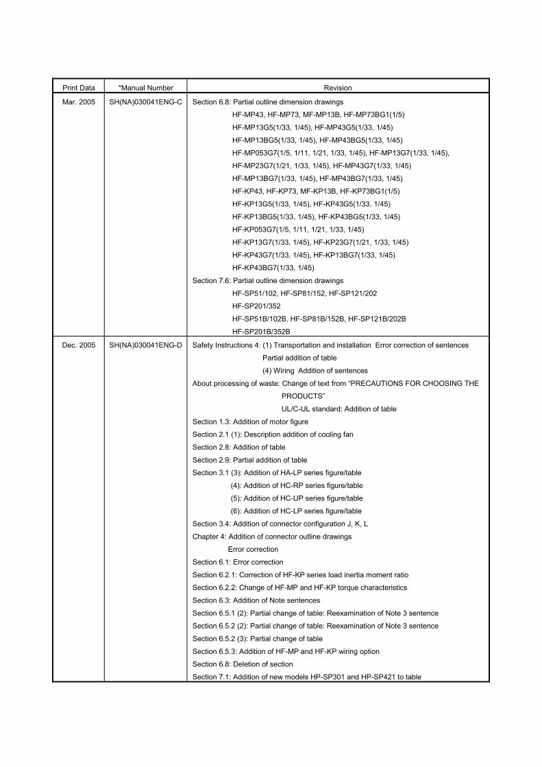
Print Data *Manual Number Revision
Mar. 2005 SH(NA)030041ENG-C Section 6.8: Partial outline dimension drawings
HF-MP43, HF-MP73, MF-MP13B, HF-MP73BG1(1/5)
HF-MP13G5(1/33, 1/45), HF-MP43G5(1/33, 1/45)
HF-MP13BG5(1/33, 1/45), HF-MP43BG5(1/33, 1/45)
HF-MP053G7(1/5, 1/11, 1/21, 1/33, 1/45), HF-MP13G7(1/33, 1/45),
HF-MP23G7(1/21, 1/33, 1/45), HF-MP43G7(1/33, 1/45)
HF-MP13BG7(1/33, 1/45), HF-MP43BG7(1/33, 1/45)
HF-KP43, HF-KP73, MF-KP13B, HF-KP73BG1(1/5)
HF-KP13G5(1/33, 1/45), HF-KP43G5(1/33, 1/45)
HF-KP13BG5(1/33, 1/45), HF-KP43BG5(1/33, 1/45)
HF-KP053G7(1/5, 1/11, 1/21, 1/33, 1/45)
HF-KP13G7(1/33, 1/45), HF-KP23G7(1/21, 1/33, 1/45)
HF-KP43G7(1/33, 1/45), HF-KP13BG7(1/33, 1/45)
HF-KP43BG7(1/33, 1/45)
Section 7.6: Partial outline dimension drawings
HF-SP51/102, HF-SP81/152, HF-SP121/202
HF-SP201/352
HF-SP51B/102B, HF-SP81B/152B, HF-SP121B/202B
HF-SP201B/352B
Dec. 2005 SH(NA)030041ENG-D Safety Instructions 4: (1) Transportation and installation Error correction of sentences
Partial addition of table
(4) Wiring Addition of sentences
About processing of waste: Change of text from “PRECAUTIONS FOR CHOOSING THE
PRODUCTS”
UL/C-UL standard: Addition of table
Section 1.3: Addition of motor figure
Section 2.1 (1): Description addition of cooling fan
Section 2.8: Addition of table
Section 2.9: Partial addition of table
Section 3.1 (3): Addition of HA-LP series figure/table
(4): Addition of HC-RP series figure/table
(5): Addition of HC-UP series figure/table
(6): Addition of HC-LP series figure/table
Section 3.4: Addition of connector configuration J, K, L
Chapter 4: Addition of connector outline drawings
Error correction
Section 6.1: Error correction
Section 6.2.1: Correction of HF-KP series load inertia moment ratio
Section 6.2.2: Change of HF-MP and HF-KP torque characteristics
Section 6.3: Addition of Note sentences
Section 6.5.1 (2): Partial change of table: Reexamination of Note 3 sentence
Section 6.5.2 (2): Partial change of table: Reexamination of Note 3 sentence
Section 6.5.2 (3): Partial change of table
Section 6.5.3: Addition of HF-MP and HF-KP wiring option
Section 6.8: Deletion of section
Section 7.1: Addition of new models HP-SP301 and HP-SP421 to table

Print Data *Manual Number Revision
Dec. 2005 SH(NA)030041ENG-D Section 7.2.1: Addition of new model to table
Addition of Note to table
Addition of Note 9 and 10
Section 7.2.2: Addition of new model
Change of HF-SP52 torque characteristics
Section 7.3: Addition of Note sentences
Addition of new model to table
Section 7.4: Addition of new model to table
Section 7.5: Addition of HF-SP G1(H), G5, G7
Section 7.6: Addition of new model to table
Section 7.7.1-7.7.2: Error correction
Addition of new model outline drawings
Section 7.7.3-7.7.10: Addition of G1(H), G5, G7 outline drawings
Section 7.7.10: Error correction
Chapter 8: Addition of Chapter on HA-LP series
Chapter 9: Addition of Chapter on HC-RP series
Chapter 10: Addition of Chapter on HC-UP series
Chapter 11: Addition of Chapter on HC-LP series
Appendix Appendix.1: Addition of new model servo motor ID code
Aug. 2007 SH(NA)030041ENG-E Addition of servo motors HF-SP524/1024/1524/2024/3524
Addition of HA-LP6014, 12K14, 701M4, 15K1M4, and 22K1M4
Addition of WARNING about charge lamp off confirmation to corresponding section
Addition of WARNING about attaching magnetic contactor to corresponding section
Change of “servo amplifier” to “converter unit and servo amplifier (drive unit)”
Safety Instructions 2: To prevent fire: Sentence change
Safety Instructions 4: (1) Transportation and installation Partial addition of table
(2) Wiring Correction of figure
Compliance with EC directives: 2. Precautions for compliance (2) Addition
UL/C-UL Standard: Change of table contents
Section 1.1: Partial correction of table
Change of Note 1 and 6, and addition of Note 9 and 10
Section 2.1 (1): Correction of table sentences
Section 2.7: Addition of servo motor with oil seal
Section 3.1(2) (3): Partial addition of table
Section 6.5.2 (3): Correction of the table
Section 7.1: Table addition
Section 7.2.1: Table addition
Change of Note 1, 2, and 5
Section 7.2.2: Graph addition
Section 7.3: Partial correction of table
Section 7.4: Partial correction of table
Section 7.5: Addition of servo motor with oil seal
Section 7.6.1 (2): Partial addition of table
Note addition
(2) (b): Partial correction of table
Section 7.6.2: Partial addition of table
Section 7.8: Addition of outline dimension drawings
Section 8.1: Partial addition of table

Print Data *Manual Number Revision
Aug. 2007 SH(NA)030041ENG-E Section 8.2: Correction of values for maximum current, rated current and Current value
and power supply voltage of cooling fan
Table addition
Section 8.2.1: Addition of HA-LP6014, 12K14, 701M4, 15K1M4, and 22K1M4 to standard
specifications
Change of Note 1, 2, and 5
Addition of Note 9
Section 8.2.2: Graph addition
Section 8.3: Partial addition of table
Section 8.4: Partial addition of table
Section 8.6: Partial addition of table
Section 8.7: Addition of outline dimension drawings
Section 9.1: Table addition
Note addition
Section 9.2.1: Note addition
Section 9.5: Addition
Section 9.7: Addition of outline dimension drawings
Appendix. 1: Partial addition of table
Feb. 2008 SH(NA)030041ENG-F Change of description from “misoperation” to “unexpected operation”
Section 7.8: Change of outline dimension drawings for HF-SP201, 301, 352(4), and
502(4) because of hanging bolt location change
Section 8.7: Change of outline dimension drawings for HA-LP15K1(4), 20K1(4), 25K1(4),
30K1(4), 37K1(4), 22K1M(4), 30K1M(4), 37K1M(4), 45K1M(4), 50K1M4,
30K2(4), 37K2(4), 45K2(4), and 55K24 because of notch addition
Change of terminal box for HA-LP801(4), 12K1(4), 11K1M(4), 15K1M(4),
15K2(4) and 22K2(4)
Feb. 2009 SH(NA)030041ENG-G Change of all (JIS C0617 compliant) graphical symbols for use in electrotechinical
diagram
Safety Instructions
Section 1.1: Change of items in Compliance with Overseas Standards for HA-LP
Change of HC-LP servo motor IP rating to IP65
Deletion of Note 10
Chapter 2: Addition of WARNING
Addition of CAUTION sentences
Chapter 3: Addition of POINT sentences describing protective structure
Section 3.3: Partial change in appearance drawings and model names of wiring
connectors
Chapter 4 (3): Change in model names and outline drawings of connectors
Section 5.9: Partial change of calculation results in selection example
Section 6.1: Change of rating output value to kW
Section 7.7: Change in model names of connectors
Section 8.2.1: Change of model name of large capacity servo amplifier to DU K
Section 9.4: Partial change of variable dimensions for HC-RP353K to 503K
Section 10.4: Partial change of variable dimensions for HC-UP152K
Oct. 2010 SH(NA)030041ENG-H HF-JP servo motor addition, change of "EN standard" to "IEC/EN standard"
2. To prevent fire, note
the following
Item addition
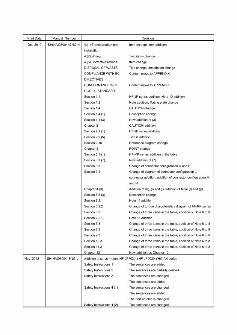
Print Data *Manual Number Revision
Oct. 2010 SH(NA)030041ENG-H 4.(1) Transportation and
installation
4.(2) Wiring
4.(5) Corrective actions
DISPOSAL OF WASTE
COMPLIANCE WITH EC
DIRECTIVES
CONFORMANCE WITH
UL/C-UL STANDARD
Section 1.1
Section 1.2
Section 1.4
Section 1.4 (1)
Section 1.4 (3)
Chapter 2
Section 2.1 (1)
Section 2.9 (b)
Section 2.10
Chapter 3
Section 3.1 (1)
Section 3.1 (7)
Section 3.3
Section 3.4
Chapter 4 (3)
Section 5.5 (3)
Section 6.2.1
Section 6.2.2
Section 6.3
Section 7.2.1
Section 7.3
Section 8.3
Section 9.3
Section 10.3
Section 11.3
Chapter 12
Item change, item addition
Two items change
Item change
Title change, description change
Content move to APPENDIX
Content move to APPENDIX
HF-JP series addition, Note 10 addition
Note addition, Rating plate change
CAUTION change
Description change
New addition of (3)
CAUTION addition
HF-JP series addition
Title is addition
Reference diagram change
POINT change
HF-MP series addition in the table
New addition of (7)
Change of connector configuration D and F
Change of diagram of connector configuration J,
connector addition, addition of connector configuration M
and N
Addition of (b), (i) and (j), addition of table (f) and (g)
Description change
Note 11 addition
Change of torque characteristics diagram of HF-KP series
Change of three items in the table, addition of Note 6 to 8
Note 11 addition
Change of three items in the table, addition of Note 6 to 8
Change of three items in the table, addition of Note 6 to 8
Change of three items in the table, addition of Note 6 to 8
Change of three items in the table, addition of Note 6 to 8
Change of three items in the table, addition of Note 6 to 8
New addition as Chapter 12
Nov. 2012 SH(NA)030041ENG-J Addition of servo motors HF-JP703(4)/HF-JP903(4)/HG-AK series
Safety Instructions 1
Safety Instructions 2
Safety Instructions 3
Safety Instructions 4 (1)
Safety Instructions 4 (2)
The sentences are added.
The sentences are partially deleted.
The sentences are changed.
The sentences are added.
The sentences are changed.
The sentences are added.
The part of table is changed.
The sentences are changed.

Print Data *Manual Number Revision
Nov. 2012 SH(NA)030041ENG-J Safety Instructions 4 (4)
Safety Instructions 4 (5)
Safety Instructions 4 (6)
COMPLIANCE WITH CE
MARKING
Section 1.1
Section 1.2
Section 1.3
Section 1.4
Section 1.4 (1)
Section 1.4 (2)
Section 1.4 (3)
Section 1.5
Chapter 2
Section 2.1
Section 2.4
Section 2.8
Section 2.9
Section 3.1
Section 3.2
Section 3.3
Section 3.4
Section 3.5
Chapter 4
Section 5.5 (3)
Section 6.2.1
Section 6.2.2
Section 6.3
Section 6.8
Section 7.2.2
Section 7.3
Section 8.2.1
Section 8.3
Section 8.4
Section 8.8
Section 9.3
Section 9.7.4
Section 9.7.6
Section 9.8
The sentences are changed.
The sentences are added.
The sentences are changed.
The sentences are changed.
Title is changed.
The part of table is changed.
Note 10 is changed.
The diagram is changed.
The diagram is added.
The sentences are changed to CAUTION.
The sentences are added to CAUTION.
The sentences are changed.
The sentences are added.
The sentences are added.
The sentences are added.
The sentences are changed.
The diagram is changed.
The sentences are changed to CAUTION.
The part of table is changed.
The sentences are changed to CAUTION.
The sentences are changed to CAUTION.
The table is changed.
The table is changed.
The part of table is changed.
The table is added.
The part of table is changed.
The part of table is changed.
Addition
The part of diagram is changed.
POINT is added.
The sentences of Note 11 are changed.
The sentences are changed.
The part of diagram is changed.
The sentences are added to CAUTION.
The sentences are changed.
The sentences are changed.
The part of diagram is changed.
The sentences are added to CAUTION.
The part of table is changed.
The sentences are added to CAUTION.
The part of diagram is changed.
Addition
The sentences are added to CAUTION.
The part of diagram is changed.
The part of diagram is changed.
Addition

Print Data *Manual Number Revision
Nov. 2012 SH(NA)030041ENG-J Section 10.2.2
Section 10.3
Section 10.7
Section 11.2.2
Section 11.3
Section 11.7
Section 12.1
Section 12.2.1
Section 12.2.2
Section 12.3
Section 12.4
Section 12.5
Section 12.6
Section 12.7
Chapter 13
Appendix 1
Appendix 2
Appendix 3
The sentences are changed.
The sentences are added to CAUTION.
Addition
The sentences are changed.
The sentences are added to CAUTION.
Addition
The part of table is changed.
The part of table is changed.
The sentences are changed.
The part of diagram is changed.
The sentences are added to CAUTION.
The part of table is changed.
The part of table is changed.
The part of table is changed.
The diagram is added.
Addition
Addition
The part of table is changed.
The sentences are changed.
The part of table is changed.
Apr. 2013 SH(NA)030041ENG-K Section 3.1 (8)
Section 5.9 (8) to (10)
Section 13.6
The part of diagram is changed.
Some numbers are changed.
The part of diagram is changed.
Mar. 2018 SH(NA)030041ENG-L 3. To prevent injury, note
the following
4. Additional instructions
Section 1.2
Section 1.4
Section 1.5
Chapter 2
Section 2.3
Section 2.8
Section 2.9
Section 2.10
Section 2.11
Section 3.2
Section 3.3
Chapter 4
Section 6.2.1
Section 6.3
Section 6.5
Section 6.5.1
Section 6.5.2
Section 6.7
Section 7.2.1
Section 7.3
Section 7.6.1
Section 7.6.2
Partially changed.
Partially changed.
Partially changed.
Partially changed.
Partially changed.
The sentences are added to CAUTION.
The sentences are added to CAUTION.
The sentences are added to CAUTION.
Partially changed.
Partially changed.
Newly added.
Partially changed.
Partially changed.
Partially changed.
Partially changed.
Partially changed.
The sentences are added to CAUTION.
Partially changed.
Partially changed.
Partially changed.
Partially changed.
Partially changed.
Partially changed.
Partially changed.

Print Data *Manual Number Revision
Mar. 2018 SH(NA)030041ENG-L Section 7.8.3
Section 7.8.5
Section 8.2.1
Section 8.2.2
Section 9.2.1
Section 9.3
Section 9.5
Section 10.2.1
Section 11.2.1
Section 11.3
Section 12.2.1
Section 12.3
Section 13.2.1
Section 13.3
App. 2
App. 3
App. 4
Partially changed.
Partially changed.
Partially changed.
Partially changed.
Partially changed.
Partially changed.
Partially changed.
Partially changed.
Partially changed.
Partially changed.
Partially changed.
Partially changed.
Partially changed.
Partially changed.
Partially changed.
Partially changed.
Partially changed.
This manual confers no industrial property rights or any rights of any other kind, nor does it confer any patent licenses. Mitsubishi Electric Corporation cannot be held responsible for any problems involving industrial property rights which may occur as a result of using the contents noted in this manual.
© 2003 MITSUBISHI ELECTRIC CORPORATION

MEMO

MELSERVO is a trademark or registered trademark of Mitsubishi Electric Corporation in Japan and/or other countries. Cyclo is registered trademark of Sumitomo Heavy Industries. All other product names and company names are trademarks or registered trademarks of their respective companies.

Warranty
1. Warranty period and coverage We will repair any failure or defect hereinafter referred to as "failure" in our FA equipment hereinafter referred to as the "Product" arisen during warranty period at no charge due to causes for which we are responsible through the distributor from which you purchased the Product or our service provider. However, we will charge the actual cost of dispatching our engineer for an on-site repair work on request by customer in Japan or overseas countries. We are not responsible for any on-site readjustment and/or trial run that may be required after a defective unit are repaired or replaced.
[Term]
The term of warranty for Product is twelve (12) months after your purchase or delivery of the Product to a place designated by you or eighteen (18) months from the date of manufacture whichever comes first (“Warranty Period”). Warranty period for repaired Product cannot exceed beyond the original warranty period before any repair work.
[Limitations]
(1) You are requested to conduct an initial failure diagnosis by yourself, as a general rule. It can also be carried out by us or our service company upon your request and the actual cost will be charged. However, it will not be charged if we are responsible for the cause of the failure.
(2) This limited warranty applies only when the condition, method, environment, etc. of use are in compliance with the terms and
conditions and instructions that are set forth in the instruction manual and user manual for the Product and the caution label affixed to the Product.
(3) Even during the term of warranty, the repair cost will be charged on you in the following cases;
(i) a failure caused by your improper storing or handling, carelessness or negligence, etc., and a failure caused by your
hardware or software problem
(ii) a failure caused by any alteration, etc. to the Product made on your side without our approval
(iii) a failure which may be regarded as avoidable, if your equipment in which the Product is incorporated is equipped with a
safety device required by applicable laws and has any function or structure considered to be indispensable according to a common sense in the industry
(iv) a failure which may be regarded as avoidable if consumable parts designated in the instruction manual, etc. are duly
maintained and replaced
(v) any replacement of consumable parts (battery, fan, smoothing capacitor, etc.)
(vi) a failure caused by external factors such as inevitable accidents, including without limitation fire and abnormal fluctuation of
voltage, and acts of God, including without limitation earthquake, lightning and natural disasters
(vii) a failure generated by an unforeseeable cause with a scientific technology that was not available at the time of the shipment
of the Product from our company
(viii) any other failures which we are not responsible for or which you acknowledge we are not responsible for
2. Term of warranty after the stop of production (1) We may accept the repair at charge for another seven (7) years after the production of the product is discontinued. The
announcement of the stop of production for each model can be seen in our Sales and Service, etc.
(2) Please note that the Product (including its spare parts) cannot be ordered after its stop of production.
3. Service in overseas countries Our regional FA Center in overseas countries will accept the repair work of the Product. However, the terms and conditions of the repair work may differ depending on each FA Center. Please ask your local FA center for details.
4. Exclusion of loss in opportunity and secondary loss from warranty liability
Regardless of the gratis warranty term, Mitsubishi shall not be liable for compensation to:
(1) Damages caused by any cause found not to be the responsibility of Mitsubishi.
(2) Loss in opportunity, lost profits incurred to the user by Failures of Mitsubishi products.
(3) Special damages and secondary damages whether foreseeable or not, compensation for accidents, and compensation for damages to products other than Mitsubishi products.
(4) Replacement by the user, maintenance of on-site equipment, start-up test run and other tasks.
5. Change of Product specifications
Specifications listed in our catalogs, manuals or technical documents may be changed without notice.
6. Application and use of the Product (1) For the use of our General-Purpose AC Servo, its applications should be those that may not result in a serious damage even if any
failure or malfunction occurs in General-Purpose AC Servo, and a backup or fail-safe function should operate on an external system to General-Purpose AC Servo when any failure or malfunction occurs.
(2) Our General-Purpose AC Servo is designed and manufactured as a general purpose product for use at general industries.
Therefore, applications substantially influential on the public interest for such as atomic power plants and other power plants of electric power companies, and also which require a special quality assurance system, including applications for railway companies and government or public offices are not recommended, and we assume no responsibility for any failure caused by these applications when used In addition, applications which may be substantially influential to human lives or properties for such as airlines, medical treatments, railway service, incineration and fuel systems, man-operated material handling equipment, entertainment machines, safety machines, etc. are not recommended, and we assume no responsibility for any failure caused by these applications when used. We will review the acceptability of the abovementioned applications, if you agree not to require a specific quality for a specific application. Please contact us for consultation.
SH(NA)030041ENG-L

SH(NA)030041ENG-L(1803)MEE Printed in Japan Specifications are subject to change without notice. This Instruction Manual uses recycled paper.
MODEL
MODELCODE
General-Purpose AC Servo
L
SE
RV
O M
OT
OR
INS
TR
UC
TIO
N M
AN
UA
L (V
ol.2)
MOTOR INSTRUCTION(VOL.2)
1CW951
HEAD OFFICE: TOKYO BLDG MARUNOUCHI TOKYO 100-8310
MODEL
HF-MPHF-KPHF-SPHA-LPHC-RPHC-UPHC-LPHF-JPHG-AKSERVO MOTOR INSTRUCTION MANUAL (Vol.2)
L


![Инструкция Candy COS 105 F12. Ji_efyr`hc`el`mc]i_ilh[\a`hcz. FZrbgZ mdhfie_dlh\ZgZgZeb\guf reZg]hf k gZdh-g_qgbdZfbkj_av[hc 3/4" ^eyih^kh_^bg_gbyfZrbgu ddjZgmoheh^ghc\h^u](https://static.cupdf.com/doc/110x72/5f51574fe5f918157102c140/f-candy-cos-105-f-12-jiefyrhcelmciilhahcz-fzrbgz-mdhfiedlhzgzgzebguf.jpg)


![Καρδιά και Νεφρική Ανεπάρκεια · [Lp(a)] ↑ CRAS Σύνδροµο Καρδιονεφρικής Αναιµίας HF CKD Anemia. CRAS: Η απειλητική](https://static.cupdf.com/doc/110x72/5e6da63979735917e955683e/-lpa-a-cras-.jpg)