Journal of American Science, 2013; 9(11) http://www.americanscience.org
http://www.americanscience.org [email protected] 45
Head and Neck Swellings Resection Control Using Intelligent Control Based on
Mach3 and Artcam Based on MRI Image
G.G.N.Geweid1, A.A.A. Nasser
2, M.Z. mostafa
3 and
D.M.El-Hennawi
4, A. Geneid
4
1 Electrical Engineering Department, Faculty of Engineering, Alexandria University, Egypt,
2 Arab Academy for Science and Technology & Maritime Transports, Alexandria, Egy
3 Electrical Engineering Department, Faculty of Engineering, Alexandria University, Egypt.
4 Faculty of Medicine, Suez Canal University, Egypt.
Abstract—In this paper a motion control system of a Head And Neck Swellings Resection (HANSR) Tool blade is described. In
many cases, the task of accessing the location of the tumor in Head and Neck is very complicated. The abnormal tissues have to be
removed without causing any injury in the adjacent structures during surgery. This paper introduces a method that uses the
conventional way of ambiguous position to the blade, after which the intelligent HANSR Tool employs a program that allows the
blade tool itself to autonomously determine the action required to move the blade into that position. Also, this blade is connected to
three Stepper motors. A Stepper motor is chosen for the HANSR Tool blade and the author also presents how to choose this motor.
The HANSR Tool blade is with single degree of freedom and motion control system for it is selected using MACH3 and
ARTCAM algorithm. This paper mainly focuses on how to apply MACH3 and ARTCAM algorithm to Control system design. The
system is designed to allow the motor to move the HNST blade to proper angular position according to the head and neck diagram.
The method is applied to a set of real data of 20 MRI images with normal and abnormal tumors. The practice showed that the system
has the characters of good performance and low cost, so it can be widely used in resection of most Head and Neck Swellings. In
experiments, an intelligent HANSR Tool was successfully engineered to use MACH3 and ARTCAM algorithm to identify tumor
location and autonomously move toward a target and the system has the characters of good performance and low cost using this
technique, so it can be widely used in resection of most Head and Neck Swellings.
[G.G.N.Gouid, A.A.A. Nasser, M.Z. mostafa and D.M.El-Hennawi. Head and Neck Swellings Resection Control
Using Intelligent Control Based on Mach3 and Artcam Based on MRI Image. J Am Sci 2013;9(11):45-52].
(ISSN: 1545-1003). http://www.jofamericanscience.org. 8
Keywords— blade motion control; driving circuit; stepper motor; MACH3; ARTCAM; HANSR Tool;
I. INTRODUCTION
Currently, resection operation of Head and Neck Swellings is manual using classic tools (1). Motion control is one of the main factors that prevent the Automatic Operation. These Swellings are located in complicated regions of the head and neck diagram. Motion control design to access the desired location of the tumor is to be removed without causing any injury of the adjacent structures (2). Head and neck tumor consists of heterogeneous groups of tumors with a multitude of histologies. It is the sixth most common sited neoplasm in the body today with 500,000 cases expected every year(3). Early diagnosis and treatment are important in improving survival in any form of malignancy (4). Any delay may lead to more advanced disease, decrease cure rate and effectiveness of treatment, leading to higher morbidity and mortality (5). Head and neck tumor usually originates in the lining of the mouth, nose, throat, or sinuses, or in glands in the neck. There are several types of head and neck tumor, including oral tumor (e.g., tongue tumor, lip tumor, mouth tumor) and throat tumor (e.g., laryngeal tumor) (2). The symptoms of Head and neck tumors depend on tumor size, type, and location. Symptoms may be caused when a tumor presses on a nerve or damages a certain area of the Head and neck. They also may be caused when the Head and neck swells or fluid builds up within the skull. Head and neck tumors are
composed of cells that exhibit unrestrained growth in the brain (3). This paper deals with a new motion control technique for head and neck tumors removal operation. In this paper, we use three Permanent Magnet Stepper Motors (PMSM) in order to make a robust controller because PMSMs have the capability to cover and minimize all uncertainties of the model. A Stepper motor is an electromechanical nonlinear motor which has been designed to rotate in specific angular position. Stepper motors require simple and cheap controllers for position and speed control. Therefore, these motors are very popular in medical applications and are widely used in different industries(6). Permanent magnet stepper motors have become a popular alternative to the traditionally used brushed DC motors (BDCM) for many high performance motion control applications for several reasons: better reliability because of the elimination of mechanical brushes, better heat dissipation as there are no rotor windings, higher torque-to-inertia ratio, lower price and easy interfacing with digital systems(7). The shaft of a stepper motor rotates in discrete step increments when electrical command pulses are applied to it in the proper sequence (8). Rotation of the motors has several direct relationships to these applied input pulses. So, the changes in shaft position can generate oscillations or cause a long delay in the output (torque) which is related to selected
Journal of American Science, 2013; 9(11) http://www.americanscience.org
http://www.americanscience.org [email protected] 46
controller(9).Today, PMSMs are widely used in numerous motion control applications such as robotics, printers, and digital control circuits etc. Recently, various methods have been introduced for rotor positioning control and determination of proper control signals in PMSMs (10). It is important that a nonlinear controller will be required due to nonlinear structure of PM stepper motors while output tracking problem is represented(11). In recent decades, adaptive algorithms have been applied to PM stepper motors more than before. Also, motion control system of HANSR Tool blade is based on MACH3 and ARTCAM algorithms. These algorithms are deals with the 3D and 2D images. To be able to control a motion process, the precise position of objects needs to be direct access. Using a MACH3 and ARTCAM algorithms and processing the information contained in the acquired images allow controlling the position of a HANSR tool actuator or to guide a blade towards a target object. To improve the precision, the looking part, and the actual control of the position, the moving part, are included in a MACH3 and ARTCAM algorithms. Putting an object in the correct place with the right amount of force and torque at the right time is essential for efficient Head and Neck Swellings Resection operation. MACH3 is a software package that runs on a PC and turns it into a very powerful and economical Machine Controller (12). It is a very flexible program designed to control machines such as milling machines, lathes, plasma cutters, and routers. Also, MACH3 can store the properties of up to 256 different tools. If, however, your machine has an automatic tool changer or magazine, you will have to control it yourself. Also, MACH3 provides program macro capability, but you must do the programming (12). MACH3 will control up to six axes simultaneously, coordinating their movement with linear interpolation or perform circular interpolation on two axes (out of X, Y or Z) while simultaneously linearly interpolating the other four with the angle being swept by the circular interpolation. The HANSR Tool can thus move in a tapering helical path if required. The feed rate during these moves is maintained at the value requested by your part program, subject to limitations of the acceleration and maximum speed of the axes. You can move the axes by hand with various jogging controls. MACH3 can switch the blade on, rotating in either direction, then switch it off. It can also control the rate at which it rotates (rpm) and monitor its angular position for resection of Head and Neck Swellings. In this study, The ARTCAM algorithm is designed based on images for visual servo control of a HANSR tool is presented. ARTCAM Program is a unique software program which allows users to easily create impressive, high quality blade path. ARTCAM allows importing 3D models or files from other CAD packages, which can be added to make complex and intricate 3D points. This algorithm transforms images into G-code (G-code is sometimes called G programming language). In fundamental terms, G-code is a language in which people tell computerized machine tools what to make and how to make it. The "how" is defined by instructions on where to move to, how fast to move, and through what path to move far more quickly than is possible
using conventional methods. The problem with these images is that most of them are based on pixels (e.g. jpg, bmp, gif), rather than the vector type entities (lines, circles, arcs; e.g. dxf, dwg) that are needed for HANSR tool paths. Identify the tumor location with extensive CAD drawing tools on MRI images, then create blade path based on G-code related to tumor location. This allows surgeon to move the HANSR Tool blade to proper angular position according to the input images. Finally, the combination of MACH3 and ARTCAM algorithms identifies the target and actual positions. It is then a natural step in implementing a motion control system. This allows oncologists and Ear, Nose and Throat (ENT) surgeons to control the blade motion and to see the results in real time during eradication operation. As well as giving total flexibility in the resection of most Head and Neck Swellings. Finally the software including motor controlling program, communication program and human-machine interface program are designed. We would advise the following points be considered before starting. The maximum and minimum speeds (rpm) that the blade will experience in normal operation, Pulley Ratio (an accurate ratio is required for MACH3 to be able to calculate the correct blade path to control the removal operation by motor), Motor Output Signal Setup for MACH3 Pins and Ports, blade path input required for MACH3 Ports and Pins, The correct blade path Setup under MACH3 Ports and Pins.
II. SYSTEM DESCRIPTIONS
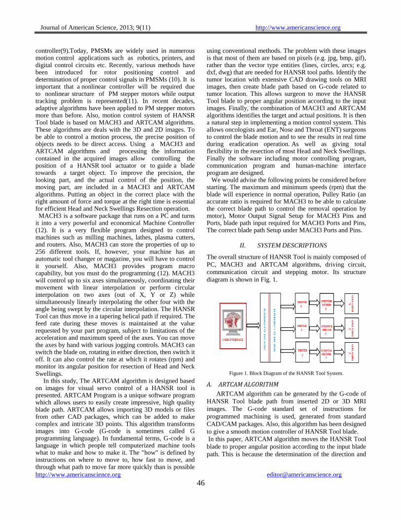
The overall structure of HANSR Tool is mainly composed of
PC, MACH3 and ARTCAM algorithms, driving circuit,
communication circuit and stepping motor. Its structure
diagram is shown in Fig. 1.
Figure 1. Block Diagram of the HANSR Tool System.
A. ARTCAM ALGORITHM
ARTCAM algorithm can be generated by the G-code of
HANSR Tool blade path from inserted 2D or 3D MRI
images. The G-code standard set of instructions for
programmed machining is used, generated from standard
CAD/CAM packages. Also, this algorithm has been designed
to give a smooth motion controller of HANSR Tool blade.
In this paper, ARTCAM algorithm moves the HANSR Tool
blade to proper angular position according to the input blade
path. This is because the determination of the direction and

Journal of American Science, 2013; 9(11) http://www.americanscience.org
http://www.americanscience.org [email protected] 47
the entry points of Head and Neck to target only the Swelling
tissues region and to avoid other organs is a difficult job.
The ARTCAM algorithm is used as an identifier to
identify the tumor location from the brain MRI images as
shown in fig.2. In addition, the Calculation technique for the
tool path motion direction in computed tomography images
is based on oncologists’ and ENT surgeons’ experience.
After that, testing of this path should be performed using a
test image set to verify the efficiency of the constructed path
and reach the optimum path allowing identification to take
place. This allows oncologists and ENT surgeons to access
the location of the tumor in Head and Neck during
eradication operation and to see the results in real time as
well as giving total flexibility in the tumor removal
operation. This is very important because the tumor has to be
removed without causing any lacerations in the adjacent
structures during entry or exit from the tumor area as shown
in fig. 2.
Figure 2. Head and neck tumors location diagram
B. MACH3 ALGORITHM
In this study, MACH3 2.0 is used to control the
motors and interface between the user input and the
driver circuit. MACH3 is low cost software available it
implements motor control from manual input or programmed
blade control. There are some requirements for proposed
system design. The first fact of MACH3 is to provide
inexpensive, programmable logic control and interfacing
to external devices. The second option is that there are about
32 I/O pins required for interfacing various input and output
devices. MACH3 is used in this study because it is
compatible with all these requirements. MACH3 generates
step pulses and direction signals to perform the steps defined
by a G-Code part program and sends them to the I/O ports.
When MACH3 receives a command from the ARTCAM
, it will be calculated into the control pulse signal by
the algorithm and outputted through I/O port to driving the
stepper motor. Its control is totally by computer and has
vision capability which leads its blade to certain places.
After finding the target coordinates, the control orders are
given to blade by computer through parallel port to the
interface circuit. These commands can turn off/on stepper
motor through drive circuit in order to move blade to
correct direction. The G-Code window and blade path
displays provide information from MACH3 to oncologists
and ENT surgeons. The software provides functions
including system configuration, combination code
generator, program editor, terminal emulator, and
program tester. With communication to the PC card and
the indexer, the program can be used to control the
system upon selection of the type of motor controller as
shown in fig.3. The MACH3 algorithm automatically
generates controller code for the basic system set-up
parameters such as distances and speeds. The editor is used
to provide a programmable environment to create blocks or
lines of code.
Figure 3. MACH3 software control panel
C. Stepper Motor
A stepper motor is an electromechanical device which
converts electrical pulses into discrete mechanical
movements. The shaft or spindle of a stepper motor rotates
indiscrete step increments when electrical command pulses
are applied to it in the proper sequence. Rotation of the
motors has several direct relationships to these applied input
pulses (11, 13). The stepper used in this study has 200 steps
per revolution. The relationship between steps per
revolution and step angle is given by the following formula;
(1)
It is found that the step angle is 1.8 degrees in a step. In this
study, The stepping motors are used to drive the
positioning tool blade in X and Y directions and the
cutter in Z direction. The motors used are two phase
bipolar stepping motors with 1.8 degrees per step. The rated
voltage for one of them is 5 V DC and 3.2 V DC for the
other.
In this study, we have a standard step motor with 200
steps per revolution. This motor is driven by a driver set to 5
micro steps per full step. The motor is directly coupled to
the lead blade which has a pitch of 5mm per revolution.
That means the axis will move 5mm for each revolution of
the blade. So we’ll take the motors 200 steps multiply that

Journal of American Science, 2013; 9(11) http://www.americanscience.org
http://www.americanscience.org [email protected] 48
by the drives 5 micro step. (200 X 5 = 1000). The drive
needs 1000 pulses (or steps) to turn the blade one revolution
thus making the axis move 5mm. So now we take those
1000 steps and divide by the pitch of the blade, which is 5.
(1000 / 5 = 200). In other words we need 200 steps to move
one unit or mm.
D. Stepper Motor Driver Circuit
The drive circuits are used to drive the two phase
bipolar X,Y and Z stepper motors. The drive circuit to drive
the X and Y axes is given in Fig. 4. while the circuit for
driving the Z axis is given in Fig. 5.The principal
function of the driver circuits is to generate motor phase
sequences.
In these circuits L298 dual full-bridge driver and L297
stepper motor controller IC are used as motor drive circuit
components. There are three control signals, which are used
to control each of the motor axes, as “clock” to give the
stepping command, “direction” to determine the sense of
rotation of the motor and “half/full” to decide whether to
operate in full or in half step mode(14). Although it is
possible to choose full or half step mode, only the full step
mode is used as indicated before. Normal drive mode is
practiced to the full step mode and it is selected by a low
logic level on Half/Full input (Full step mode)(8,13). The
cable connection used between the stepper motor controller
circuit inputs to the proper outputs in order to drive the step
motors are given in Table 1, Table 2 and Table 3.
TABLE 1. Cable connection of X-Y axis card
TABLE 2. Cable connection of Z axis card
TABLE 3. Cable connection of cards and supply
Figure 4. (X-Y) Axis Drive Circuit

Journal of American Science, 2013; 9(11) http://www.americanscience.org
http://www.americanscience.org [email protected] 49
Figure 5. Z Axis Drive Circuit
E. Digital I/O
1) Requirements for Digital I/O :Base drive
circuit is designed such that the control signals are at
TTL logic level which is 0 or 5 Volts. In order to have
maximum efficiency in the system, these control signals
must be as fast as possible (14). This speed depends
on the torque requirement from the motor, simply
the physical characteristics of the material are drilled,
and the control scheme of the motors. Closed-loop
control scheme will require faster signals than the
open-loop case. Experimental results show that with the
open-loop control scheme, motor types and material
given, 5msec, as the step motor pulse duration is
adequate. These signals may be generated by specially
designed, commercially available professional devices
that are sold by various vendors with respectively
higher prices. Another solution for digital I/O is utilizing
the parallel port which is available on every personal
computer (8,15).
2) Parallel Port of PC :Parallel port is a standard
I/O interface for all PCs. Today, there exists at least one
parallel port for various applications such as connection
of a printer or a hard-key. In Table 4, the base hardware
addresses of the parallel ports are given.
TABLE 4. Parallel Port Address Table
There are three types of I/O interface in the parallel port
namely data port, status port and control port.
Data Port: There exist eight digital output
terminals that are accessed by dataports.
Status Port: There exist five digital input
terminals, of which one of them is inverted, that
are accessed by status ports.
Control Port : There exist four digital output
terminals, of which three of them are inverted,
that are accessed by control ports.
All ports are defined at TTL (Transistor-Transistor
Logic) logic levels (An electrical "high" on the pin is
TTL high, +2.4 to +5 volts. An electrical "low" is TTL
low, 0 to +0.8 volts.). Data port is driven by the high
impedance octal D-type flip-flop (74LS374). This IC
can source 2.6 mA while it can sink 24 mA. As these
values are relatively low, it may be necessary to
amplify the outputs for specific applications. Control
port pins are driven by the 7405 inverter IC which may
supply 1 mA up to 7 mA. In parallel port applications,
for not to damage the mainboard the driver circuits
should fulfill the requirements given above.
In Fig. 6, the block diagram of the parallel
interface is given while in Fig. 7. the illustration of a
parallel port is shown.
Figure 6. Block diagram of the parallel interface
Figure 7. Parallel Port I/O Scheme
Journal of American Science, 2013; 9(11) http://www.americanscience.org
http://www.americanscience.org [email protected] 50
III. SYSTEM OPERATION
This study is designed to control the blade movement system of the HANSR Tool path. Therefore a three Stepper motors is used. These motors are used to control the direction of the blade for X, Y and Z-axis. A MACH3 is also used to drive the three motors. Motors convert current into torque which produces motion. Motor’s torque properly to move the blade at the required speed and acceleration must be determined for each motion.
When the operation is started, the blade moves forward to the target position and then moves upward to the tumor location. Then the tool blade rotates in order to pick up the tumor tissues for the blade after catching the desired tumor tissue from the operation area or tumor location, the blade moves downward and moves backward to the operating area.
A. Stepper Motor Control
One of the critical points in the software is to send
the data to the driver circuit properly i.e. to the right
axis with the right timing. To determine the movement
axes that should in fact determine which bits of the
parallel port to change
. According to the axes and movement determined, the
signals are generated and sent to the driver circuit. The first thing in the tuning process is to calculate
how many steps per unit of travel we have. This depends on a few things:
The amount of steps per revolution.
The step resolution of the motor drive, full step,
half step, 5, 10, 100 micro steps etc.
The reduction ratio between the motor shaft and
lead blade.
In this design, a minimum step of 0.0005” was
chosen. A stepper motor (ten micro-steps) gives 2000
steps per revolution so a 5:1 reduction (belt or gear box)
is needed between the motor shaft and lead blade to
make one step equal to 0.0005” of travel [0.0005” =
5”/(2000 x 5)], and because of the 5:1 gear reduction
one revolution of the stepper motor will result in 1” of
travel. With this design, if we get 500 rpm from the
stepper, travel will be 500 inches per minute, or 8.33
inches per second. The rapid feed of 60” would,
neglecting acceleration and deceleration time, take a
reasonable 7.2 seconds. [60” / 8.33 = 7.2].
B. Drive Circuit Operation of MACH3 Motor setup
The drive needs 2000 pulses, or steps, to turn the motor
one revolution. But since we have the 3 to 1 belt
reduction between the motor and the blade we need to
multiply the 2000 by 3 to make the screw turn one
revolution. 6000 steps will make the blade turn one
revolution, making the axis move 1/5 of an inch. To
make the axis move one inch we need the blade to make
five revolutions so 6000 X 5 = 30.000 steps per unit or
inch. In reality a step per unit value as high as 30.000
will greatly reduce the speed at which the HANSR Tool
blade can move. This is for X Axis as shown in fig.8.
Then do the same for the Y and Z axis.
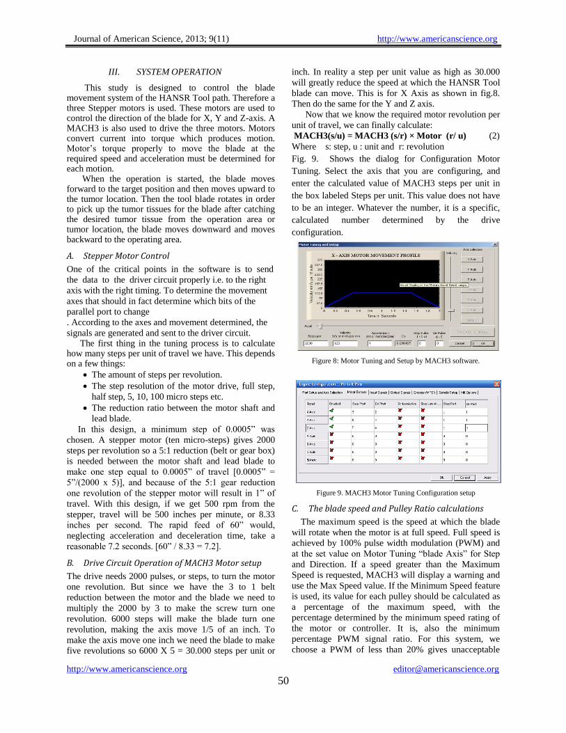
Now that we know the required motor revolution per
unit of travel, we can finally calculate:
MACH3(s/u) = MACH3 (s/r) × Motor (r/ u) (2)
Where s: step, u : unit and r: revolution
Fig. 9. Shows the dialog for Configuration Motor
Tuning. Select the axis that you are configuring, and
enter the calculated value of MACH3 steps per unit in
the box labeled Steps per unit. This value does not have
to be an integer. Whatever the number, it is a specific,
calculated number determined by the drive
configuration.
Figure 8: Motor Tuning and Setup by MACH3 software.
Figure 9. MACH3 Motor Tuning Configuration setup
C. The blade speed and Pulley Ratio calculations
The maximum speed is the speed at which the blade
will rotate when the motor is at full speed. Full speed is
achieved by 100% pulse width modulation (PWM) and
at the set value on Motor Tuning “blade Axis” for Step
and Direction. If a speed greater than the Maximum
Speed is requested, MACH3 will display a warning and
use the Max Speed value. If the Minimum Speed feature
is used, its value for each pulley should be calculated as
a percentage of the maximum speed, with the
percentage determined by the minimum speed rating of
the motor or controller. It is, also the minimum
percentage PWM signal ratio. For this system, we
choose a PWM of less than 20% gives unacceptable
Journal of American Science, 2013; 9(11) http://www.americanscience.org
http://www.americanscience.org [email protected] 51
motor performance, then the minimum speed should be
calculated as 20% of the maximum speed. If a speed
lower than the minimum is requested, then MACH3
will display a warning and use the minimum acceptable
speed. In this study, there is a maximum speed of 1600
rpm on pulley 4 and a minimum speed of 320 (20% of
1600), an S200 command would display a warning and
the minimum speed of 320 would be used. This feature
is to avoid operating the motor or its motion controller
at a speed below its minimum rating. MACH3 uses the
pulley ratio information as follows:
When the part program executes an S-word or a value
is entered into the Set Speed DRO, then the value is
compared with the maximum speed for the
currently selected pulley ratio. If the requested
speed is greater than the maximum, then an error
occurs.
Otherwise, the percentage of the maximum for the
pulley that has been requested is used to set the
PWM pulse width, or Step pulses are generated to
produce that percentage of the maximum motor
speed as set in Motor Tuning for the “blade Axis.”
In this study, suppose the maximum blade speed for
Pulley 1 is 1500 rpm. S1600 would be an error.
An S200 command would give a PWM pulse width of
40% (600/1500). If the maximum Step and Direction
speed is 3600 rpm, then the motor would be “stepped” at
1440 rpm (3600 x 0.4).The Ratio value can be set if the
actual speed of the blade is for any reason different than
the measured speed being seen by the tachometer. This
may occur if, because of physical constraints, the speed
sensor must be mounted at a point in the spindle drive
train that has additional gearing between its location and
the blade movement. Check reversed if, because of
gearing, blade rotation of a pulley setting is opposite to
the rotation of other pulley settings.
Figure 10. Pulley Ratio and blade speed calculations.
IV. TEST AND RESULT
The motion control system of a HANSR Tool blade is
operated by the ARTCAM and MACH3 2.0 software.
The algorithm is applied to 20 sets of real data in the
form of images for the adenoid and head and neck tumor
tissue before and after removal operation. These images
are classified to 12 sets of classifications (A to L)
depending on the tumor location identification. Enter
these images to the ARTCAM algorithm then start tool
path simulation. Since this software consists of many
separate path way programs which pulse a large
number of additional G-code files, it is the fact that
oncologists and ENT surgeons decide to use this
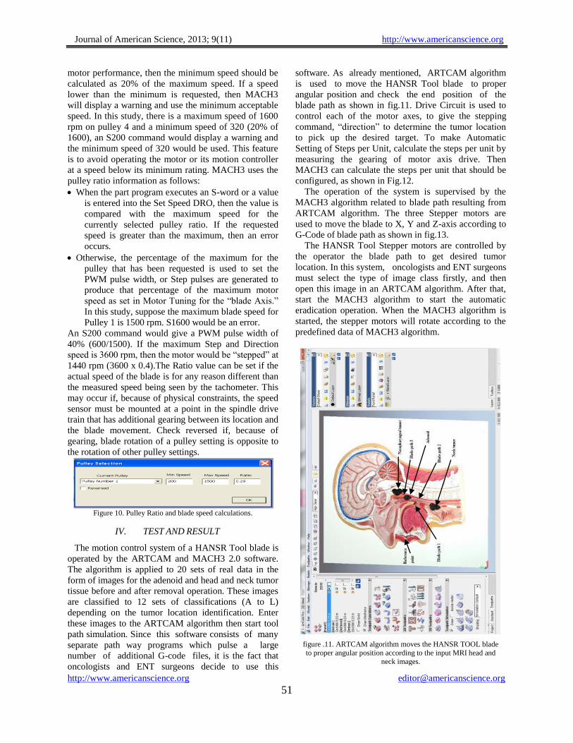
software. As already mentioned, ARTCAM algorithm
is used to move the HANSR Tool blade to proper
angular position and check the end position of the
blade path as shown in fig.11. Drive Circuit is used to
control each of the motor axes, to give the stepping
command, “direction” to determine the tumor location
to pick up the desired target. To make Automatic
Setting of Steps per Unit, calculate the steps per unit by
measuring the gearing of motor axis drive. Then
MACH3 can calculate the steps per unit that should be
configured, as shown in Fig.12.
The operation of the system is supervised by the
MACH3 algorithm related to blade path resulting from
ARTCAM algorithm. The three Stepper motors are
used to move the blade to X, Y and Z-axis according to
G-Code of blade path as shown in fig.13.
The HANSR Tool Stepper motors are controlled by
the operator the blade path to get desired tumor
location. In this system, oncologists and ENT surgeons
must select the type of image class firstly, and then
open this image in an ARTCAM algorithm. After that,
start the MACH3 algorithm to start the automatic
eradication operation. When the MACH3 algorithm is
started, the stepper motors will rotate according to the
predefined data of MACH3 algorithm.
figure .11. ARTCAM algorithm moves the HANSR TOOL blade
to proper angular position according to the input MRI head and
neck images.

Journal of American Science, 2013; 9(11) http://www.americanscience.org
http://www.americanscience.org [email protected] 52
figure 12. Automatic Setting of Steps per Unit
figure 13. The Program Run screen, with G-Code window of blade
path out.
V. CONCLUSION This paper presented an HANSR Tool blade motion control
system using a MACH3 and ARTCAM algorithm. The design
sequence of the current system is described and parameters of
three stepper motors driving are calculated at optimal values.
In this design, the MACH3 and ARTCAM algorithm are used
to build a high performance of swellings automatic removal
operation. This is the technique that causes minimum injury or
damage to the healthy tissues adjacent to the swelling site
during entry or exit from the target area. The experimental
results verify the performance of the blade motion control.
ACKNOWLEDGMENT
I can't find the suitable words to express about my deepest grateful to Prof.
Abed Elmeneam A.A. Nasser for his constant professional support, excellent
expertise and motivating discussions throughout this work.
I would like to express special thanks my advisor Prof. Mohamed Z.
Mostafa and Prof. Deiaa M. El-Henawy. For his invaluable a device and
encouragement during this research.
A special dept of gratitude and cordial appreciation is paid to Dr. Ahmed
Geneid for his constant professional support, excellent expertise and motivating
discussions throughout this work.
I also want to thank dr. ahmed sallam and eng. Ashraf sallam for their great
assistance, continuous support and encouragement.
REFERENCES [1] Kowalski LP, Carvalho AL. Influence of time delay and clinical
upstaging in the prognosis of head and neck cancer. Oral Oncol. 2011; 37(1): 94-8.
[2] http://www.emory.edu/ANATOMY/AnatomyManual/pharynx.htm.
[3] Prasad U, Pua KC. Nasopharyngeal carcinoma: a delay in diagnosis. Med J Malaysia 2005; 55(2): 230-5.
[4] Fanucchi M, Khuri FR, Shin D, Johnstone PAS, Chen A. Update in the management of head and neck cancer. Update Cancer Ther 2006; 1: 211-9
[5] Huang HM, Chao MC, Chen YL, Hsiao HR. A combined Method of conventional and endoscopic adenoidectomy. Laryngoscope 1998; 108:1104-6.
[6] R.C. Speagle and D.M. Dawson, “Adaptive Tracking Control of Permanent Magnet Stepper Motor Driving a Mechanical Load”, IEEE Conference, 1993.
[7] F. Nollet, T. Floquet and W. Perruquetti, “Observer based Second Order Sliding Mode Control Laws for Stepper Motors”, Control Engineering Practice, Vol. 16, pp. 429-443, 2008.
[8] AN1495, Application Note, “Microstepping Stepper Motor Drive Using Peak Detecting Current Control”, Thomas Hopkins,(2010),pp 4-9.
[9] M. Zribi, H.S. Ramirez and A. Ngai, “Static and Dynamic Sliding Mode Control Schemes for a Permanent Magnet Stepper Motor”, International Journal of Control, Vol. 74, pp. 103-117, 2001.
[10] S.S. Ge, C.C. Hang and T. Zhang, “A Direct Method for Robust Adaptive Nonlinear Control with Guaranteed Transient Performance”, Systems and Control Letters, Vol. 37, pp. 275-284, 2002.
[11] Perriard, Y., Scaglione, O. and Markovic, M. “Self-Sensing Methods for PM Motors in Mechatronics Applications”. Proceedings of the IEEE/ASME International Conference on Advanced Intelligent Mechatronics (AIM 2010).
[12] ArtSoft USA. software incorported; MACH3 Controller Software Installation and ConfigurationVersion 3; 2010.
[13] SGS Thompson Microelectronics, “Stepper Motor Controllers”, August 2010.
[14] Semih Mümin Ateş, “A PC Controlled Three Dimensional Machine Tool Control System”, METU MS Thesis, Dec. 2008.
[15] Oliver Faugeras, “Three Dimensional Computer Vision: A Geometric Viewpoint”, MIT Press, 1998.
11/21/2013