GWC Valve InternationalP
ro
ve
n t
ec
hn
ol
og
y f
or
in
div
idu
al
va
lv
e s
ol
ut
ion
s –
wo
rl
dw
ide
cast steel valvesgate, gloBe & checKPressure class: asMe 150-1500
siZe range: 2” - 60”
aPi standards: 600 & 603
asMe B16.34
catalog nuMBer csv-1003


gw
c v
alv
e i
nt
er
na
tio
na
l
3
taBle of contents
Cast steel Gate ValVes
Class 150 10Class 300 11 Class 600 11 Class 900 12 Class 1500 12
Gate Valve Standard Features 4Globe Valve Standard Features 6Swing Check Valve Standard Features 8Ordering Guide 9
Cast steel Globe and anGle ValVes
Class 150 13 Class 300 14 Class 600 14 Class 900 15 Class 1500 15
Class 150 16 Class 300 17 Class 600 17 Class 900 18 Class 1500 18
Cast steel swinG CheCk ValVes
Class 150 19 Class 300 19
Cast stainless steel Gate ValVes
Class 150 20 Class 300 20
Cast stainless steel Globe ValVes
Cast stainless steel swinG CheCk ValVes
Class 150 21 Class 300 21
O-Ring Seal Block & Bleed Gate Valves 22Cast Steel Cryogenic Gate, Globe and Check Valves 24Pressure–Temperature Ratings 26Terms and Conditions of Sale 28Return Goods Policy, Warranty 29

gw
c v
alv
e i
nt
er
na
tio
na
l
4
gate valve standard features
GWC Gate Valves are manufactured to the latest edition of API Standard 600 and tested to API Standard 598.
aPPlication & functionGate valves are primarily used for stop valves fully opened or fully closed. They are not normally considered for throttling purposes, but more for slurries, viscous fluids, etc.
Gate valves are characterized by a traveling wedge, which is moved with the operation of the stem nut. The wedge travels perpendicular to the direction of the flow.
Gate valves usually have a minimum pressure drop when fully open, provide tight shut-off when fully closed, and remain relatively free of contamination buildup.
Body & BonnetThe design of the body and bonnet is calculated to achieve the most regular distribution of stress in all directions, as well as the minimum turbulence and resistance to flow.
Valve bonnets are equipped with a backseat bushing. The yoke is integrally cast on Pressure Classes 150 and 300 up to 12” and up to 10” on Class 600 and higher ratings.
Body-Bonnet JointStandard body-bonnet joints of gate valves are machined as follows:
PRESSURE CLASS JOINT DESIGN 150 Flat Faced 300, 600 Male-and-Female 900* & over Ring Type Joint
*Pressure Class 600 also available in Ring Type Joint.
GWC can supply any style of gasket required by customer.
gateAll gates are fully guided to the seats. As standard our valves are supplied with a solid flexible gate that has a tapered H cross-section. The flexible wedge is cast or machined with a circumferential groove to allow the seating surfaces to move independently and adjust to movement of the body seats. This design is beneficial where line loads or thermal expansion of the system is likely to distort the seat face in the valve. This design of gate is ideally suited for steam or other high temperature services and is especially useful to prevent sticking where valves are closed when hot and opened when cold.
seat ringSeat rings are designed to greatly reduce and/or prevent any turbulence and avoid damages due to the corrosion. The seat rings are forged or rolled in one piece, and then seal welded and overlaid, if required. After welding and all required heat treating, the seat ring faces are machined, thoroughly cleaned and inspected before leaving for assembly.
steMThe stem connection to the gate is a T-head design which is integral (without welding) with the stem. The accuracy in the dimensions and finishes assure a long life with a perfect tightness in the packing area, resulting in lower fugitive emissions.
The stem-to-gate connection is designed to prevent the turning or the disengagement of stem from the wedge while the valve is in service.
Gland Adjustment Nut
Gland Eyebolt
Gland Proper
Gland Eyebolt Pin
Handwheel Nut
Handwheel
Yoke CapStem Nut
Stem
Gland Flange
Packing
Backseat Bushing
Bonnet Bolt
Bonnet
Bonnet Nut
Gasket
Gate
Body
Body Seat Ring
Nameplate

gw
c v
alv
e i
nt
er
na
tio
na
l
5
Through calculations and extreme testing, the strength of the stem-to-gate connection has proven to exceed the strength of the stem at the root of its operating thread.
steM PacKingThe stem packing is designed and arranged to ensure a maximum seal along the stem during operation or while at position, thus allowing for a greater reduction in fugitive emissions. Our packings are NON-ASBESTOS types.
GWC can supply any style of packing required by our customer.
stuffing BoXThe depth of the stuffing box allows for a sufficient amount of packing, which makes the stem seal. Our standard packing arrangement and stuffing box design meets <100 ppm fugitive emission requirements.
If specified in the purchase order, lantern rings and/or grease injectors can be furnished.
PacKing glandThe packing gland design is a two-piece self-aligning type. The packing gland has a spherical head that rides within the spherical joint of the gland flange. The packing gland has a shoulder, which restricts the complete entry into the stuffing box bore. This particular design assures a straight compression of the packing as the gland eyebolts are being equally adjusted, without injuring the stem.
steM nutThe stem nut arrangement and design allows for the removal of the handwheel without allowing the stem and gate to drop into the closed position if the handwheel is removed while the valve is in the open position.
Ball bearings are provided in the stem nut arrangement of Class 150 valves from NPS 14”, on Class 300 valves from NPS 12:, on Class 600 valves from NPS 6”, and on Classes 900-1500 valves from NPS 2”.
handwheelsHandwheels are designed for easy operation and a comfortable grip. Our valves are also available with gearing, motor actuators or cylinder actuators for the more demanding services.
Bolts and nutsFor normal service conditions, ASTM A194 Class 2H and ASTM A193 Grade B7 nuts and stud bolts are furnished. If specified for high temperature service conditions, ASTM A194 Class 4 and ASTM A193 Grade B16 nuts and stud bolts are furnished. Standard bolting furnished for our stainless steel valves consists of ASTM A194 Class 8 and ASTM A193 Grade B8 nuts and stud bolts.
GWC can supply any bolting as required by the customer.
end connectionsOur standard production covers valves with:
•FlangeendswithRaisedFace(RF),FlatFace(FF)orRingTypeJoint(RTJ)thatconform to B16.5.
•Butt-weldingends(BW)thatconformtoB16.25.•Allface-to-face/end-to-enddimensionsconformtoB16.10.•Otherspecialendconnectionsaresuppliedaccordingtocustomer’srequirements.
accessoriesAccessories such as gear operators, actuators, bypasses, locking devices, chainwheels, extended stems and bonnets for cryogenic service and many others are available to meet the customers requirements.
gate valve standard features

gw
c v
alv
e i
nt
er
na
tio
na
l
6
gloBe valve standard features
GWC Globe Valves are manufactured and modified to the latest edition of API Standard 600/ASME B16.34 and tested to API Standard 598.
aPPlication & functionGlobe valves are primarily used as control valves where throttling or both throttling and shut-off are required. Globe valves can also be used for on-off service; however, because of the design, a pressure drop becomes inherent. This is generally confined to on-off applications where the valve is normally closed and pressure drop is not important when the valve is open. Normal applications will find the globe valve with the flow and pressure under the disc. GWC cast steel globe valves are commonly made in outside screw and yoke designs with full ports (including seat ring) and heavy-duty, conical plug type discs.
Body & BonnetThe body is full ported and spherical in form. The design utilizes
large radiuses which allow for the stresses, flow resistance and turbulence to be kept to a minimum. Valve bonnets are equipped with a backseat bushing.
Body-cover JointStandard body-cover joints of our globe valves are machined as follows:
PRESSURE CLASS JOINT DESIGN150, 300, 600 Male-and-Female900* & over Ring Type Joint
*Pressure Class 600 also available in Ring Joint Type
GWC can supply any style of gasket required by the customer.
discThe valve is normally supplied with the conical plug type disc. The disc rotates freely on the stem and incorporates a differential angle from that on the seat ring. This design provides the maximum assurance of shut off, is less likely to stick in the body seat, and is considered the simplest design for field repair.
The disc is held onto the stem utilizing the disc nut and a split-ring disc retainer on 2”–4” in pressure classes 150 and 300. Larger sizes as well as pressure classes 600 and higher utilize the disc nut and a button head design which is integral with the stem. Bottom guided discs are available.
seat ringsSeat rings are designed to greatly reduce and/or prevent any turbulence and avoid damages due to corrosion. The seat rings are forged or rolled in one piece and then seal welded and overlaid, if required. After welding and all required heat treating, the seat ring faces are machined, thoroughly cleaned and inspected before leaving for assembly.
steMAsGWC’sstandard,allstemsarerotatingandrising;however,anon-rotatingdesignisavailable when specified by the customer. The accuracy in the dimensions and finishes assure a long life with a perfect tightness in the packing area, resulting in lower fugitive emissions. All of our stems are designed with integral backseat features which provide an ultimate seal during packing changes.
stuffing BoXThe depth of the stuffing box allows for a sufficient amount of packing, which makes thestemseal.GWC’sstandardpackingarrangementandstuffingboxdesignmeets<100 ppm fugitive emission requirements.
If specified in the purchase order, lantern rings and/or grease injectors can be furnished.
Handwheel Nut
Handwheel
Stem NutStem
Gland Adjustment Nut
PackingBackseat Bushing
Gland Proper
Gasket
Body
Disc Nut
Disc
Seat Ring
Gland FlangeGland EyeboltGland Eyebolt PinBonnet BoltBonnet NutBonnetNameplate

gw
c v
alv
e i
nt
er
na
tio
na
l
7
gloBe valve standard features
steM PacKingThe stem packing is designed and arranged to ensure a maximum seal along the stem during operation or while at position, thus allowing for a greater reduction in fugitive emissions. Our packings are of non-asbestos types.
GWC can supply any style of packing required by the customer.
PacKing glandThe packing gland design is a two-piece self-aligning type. The packing gland has a spherical head that rides within the spherical joint of the gland flange. The packing gland has a shoulder, which restricts the complete entry into the stuffing box bore. This particular design assures a straight compression of the packing as the gland eyebolts are being equally adjusted, without injuring the stem.
steM nutThestemnutsonGWC’sstandardrisingstemglobevalvesarethreadedintothetopofthe yoke where they are secured with a tack weld.
oPerationHandwheels are designed with a comfortable grip for easy operation. As our standard, hammer-blow type handwheels are provided as listed in the next column:
PRESSURE CLASS JOINT DESIGN150 8” and larger300 – 600 6” and larger900 and over 4” and larger
Our valves are also available with gearing, motor actuators or cylinder actuators for the more demanding services.
Bolts and nutsFor normal service conditions, ASTM A194 Class 2H and ASTM A193 Grade B7 nuts and stud bolts are furnished. If specified for high temperature service conditions, ASTM A194 Class 4 and ASTM A193 Grade B16 nuts and stud bolts are furnished. Standard bolting furnished for our stainless steel valves consists of ASTM A194 Class 8 and ASTM A193 Grade B8 nuts and stud bolts.
GWC can supply any bolting as requested by the customer.
end connectionsOur standard production covers valves with:
•FlangeendswithRaisedFace(RF),FlatFace(FF)orRingTypeJoint(RTJ)thatconform to B16.5.
•Butt-weldingends(BW)thatconformtoB16.25.•Allface-to-face/end-to-enddimensionsconformtoB16.10.•Otherspecialendconnectionsaresuppliedaccordingtocustomer’srequirements.
accessoriesAccessories such as gear operators, actuators, bypasses, locking devices, chainwheels, extended stems and bonnets for cryogenic service and many others are available to meet the customers requirements.

gw
c v
alv
e i
nt
er
na
tio
na
l
8
swing checK valve standard features
GWC Swing Check Valves are manufactured and modified to the latest edition of API Standard 600/ASME B16.34 and tested to API Standard 598.
aPPlication & functionSwing check valves are designed to close quickly and automatically with positive shut off in either horizontal or vertical (flow up) pipe runs.
Inherently, swing check valves have a low pressure drop and are best suitable for velocity applications.
Our closure design allows our swing check valve to close completely even and remain closed with no flow when installed in a horizontal pipe run.
BodyThe body is full ported and spherical in form. The design utilizes large radiuses which allow for the stresses, flow resistance and turbulence to be kept to a minimum. Bosses are provided for optional drains.
Body-cover JointStandard body-cover joints of our swing check valves are machined as follows:
PRESSURE CLASS JOINT DESIGN150, 300, 600 Male-and-Female900* & over Ring Type Joint
*Pressure Class 600 also available in Ring Type Joint.
GWC can supply any style of gasket required by customer.
hinge asseMBlyThehingearmpivotsonthehingepinwhichis locatednearthedisc’scenterofgravity. Bodypenetration for the hinge pin is sealed with a soft steel gasket and flanged plug. The hinge arm is designed to withstand the shock load of quick closing to insure a longer life and continued shut-off. The hinge arm also has an integral disc stop that provides a positive stop in the open position.
discEachdisc’sseatingsurfaceisprecisiongroundandmatedtotheseatringforinsuranceofapositiveshut off. The disc is secured to the hinge arm with the disc nut and pinned to prevent disengagement duringservice.Wecanprovideeitherintegraloroverlaidseatfacingsatcustomer’srequest.
seat ringSeat rings are designed to greatly reduce and/or prevent any turbulence and avoid damages due to corrosion. The seat rings are forged or rolled in one piece and then seal welded and overlaid, if required. After welding and all required heat treating, the seat ring faces are machined, thoroughly cleaned and inspected before leaving for assembly.
Bolts and nutsFor normal service conditions, ASTM A194 Class 2H and ASTM A193 Grade B7 nuts and stud bolts are furnished. If specified for high temperature service conditions, ASTM A194 Class 4 and ASTM A193 Grade B16 nuts and stud bolts are furnished. Standard bolting furnished for our stainless steel valves consists of ASTM A194 Class 8 and ASTM A193 Grade B8 nuts and stud bolts.
GWC can supply any bolting as requested by the customer.
end connectionsOur standard production covers valves with:
•FlangeendswithRaisedFace(RF),FlatFace(FF)orRingTypeJoint(RTJ)thatconformto B16.5.
•Butt-weldingends(BW)thatconformtoB16.25.•Allface-to-face/end-to-enddimensionsconformtoB16.10.•Otherspecialendconnectionsaresuppliedaccordingtocustomer’srequirements.
accessories/oPtional designsCounterweight features are available as an accessory. Piston, tilting disc or API-6D designs are also available to meet the customers requirements. Drains and bypasses are available as specified by the customer.
Cover Bolt
Cover Nut
Gasket
Cover
Hinge ArmHinge Pin
Body
Seat Ring
Washer
Disc Nut
Split Pin
Disc
Nameplate

gw
c v
alv
e i
nt
er
na
tio
na
l
9
ordering guide
example: 8˝ figure #1900-i-5-go
8” CLASS 900 GATE VALVE, FLG-RF, A217 WC6 BODY, WC6 DISC W/STELLITE OVERLAY,
F11 SEATS W/STELLITE OVERLAY, F6 STEM, GEAR OP.
90 0 51. 2. 4. 5. 6.
GOI13.
1. MODEL1 - API 600 GATE VALVE2 - API 600 GLOBE VALVE3 - API 600 SWING CHECK VALVE4 - API 603 GATE VALVE5 - API 603 GLOBE VALVE6 - API 603 SWING CHECK VALVE
24 - ANGLE GLOBE VALVE26 - STOP CHECK VALVE34 - TILTING DISC CHECK VALVE35 - PISTON CHECK VALVE81 - API-6D GATE VALVE83 - API-6D SWING CHECK VALVE
2. RATING 15 - CLASS 15030 - CLASS 30060 - CLASS 600
90 - CLASS 900150 - CLASS 1500
3. END CONNECTION0 - RF FLANGED6 - FF FLANGED7 - BUTTWELD
9 - RING JOINTX - OTHER
4. MATERIAL (BODy + BONNET/CAp)A - WCBB - WCCC - LCCD - LCBH - WC1I - WC6J - WC9
K - C5L - C12M - CF8N - CF8MO - CF3P - CF3MQ - CF8C
R - CN7MS - A890 4AT - A890 5AU - A890 6AX - OTHER
5. MATERIAL (TRIM)1 - 13CR8 - 13CR 1/2 STELLITE5 - 13CR FULL STELLITE2 - 304SS2S - 304SS 1/2 STELLITE15 - 304SS FULL STELLITE10 - 316SS
12 - 316SS 1/2 STELLITE16 - 316SS FULL STELLITE9 - MONEL11 - MONEL 1/2 STELLITE13 - ALLOY 2014 - ALLOY 20 1/2 STELLITE17 - 347SS
17H - 347SS 1/2 STELLITE17S - 347SS FULL STELLITE21 - F5122 - F5323 - F55O - OTHER
6. OpERATOR - HANDWHEEL OPERATORGO - BEVEL GEAR OPERATOR
B - BARE STEM
7. SpECIAL REQUIREMENTN - NACE MR-01-75S - SUPPLY COMPLETE INFORMATION
EB - EXTENDED BONNETY - “Y” PATTERN

gw
c v
alv
e i
nt
er
na
tio
na
l
10
cast steel gate valves
Model 1150 / 1157 / 1159Other materials available on request.
Cast steel gate valve, outside screw and yoke, bolted bonnet, rising stem,
non-rising handwheel, flexible wedge, available in welded seat rings,
designed according to API-600.
Dimensions in inches
eziSevlaV "2/1-1mm04
"2mm05
"2/1-2mm56
"3mm08
"4mm001
"6mm051
"8mm002
"01mm052
"21mm003
"41mm053
"61mm004
"81mm054
"02mm005
"42mm006
"03mm057
"63mm009
ecaFotecaF
FR:1L 05.6 00.7 05.7 00.8 00.9 05.01 05.11 00.31 00.41 00.51 00.61 00.71 00.81 00.02 00.42 00.82
JTR:2L 00.7 05.7 00.8 05.8 05.9 00.11 00.21 05.31 05.41 05.51 05.61 05.71 05.81 05.02 – –
WB:3L 05.6 05.8 05.9 31.11 00.21 88.51 05.61 00.81 57.91 05.22 00.42 00.62 00.82 00.23 00.63 00.04
)H(thgieHnepOevlaV 67.21 54.41 36.51 30.81 50.22 40.03 08.73 19.54 09.35 56.95 08.17 08.47 05.38 05.89 00.621 02.041
)1D(retemaiDleehwdnaH 90.7 78.7 78.7 28.8 48.9 04.21 89.31 57.51 27.71 96.91 50.22 08.42 59.72 05.13 34.53 00.34
)2D(retemaiDleehwdnaH – – – – 04.21 04.21 04.21 89.31 57.51 57.51 57.51 27.71 27.71 96.91 59.72 05.13
.)sbl(thgieWFR 63 14 85 37 601 291 482 793 816 409 972,1 884,1 658,1 240,3 036,4 004,6
WB 13 63 74 16 68 661 242 723 315 477 621,1 692,1 236,1 307,2 449,3 503,6
* 26” and larger are available with ASME B16.47 end flanges, either Series
A or Series B (formerly MSS SP-44 and API 605).
diMensions
Face to Face ASME B16.10End Flange ASME B16.5*Buttweld ASME B16.25Rating ASME Class 150
D1
H O
pen
L1,L2
H O
pen
D2
L3
Class 150
standard Parts & Materials
NO. PART NAMECARBON STEEL ALLOY STEEL STAINLESS STEEL
TYPE WCB TYPE LCC TYPE WC6 TYPE WC9 TYPE C5 TYPE C12 TYPE CF8M
1 BODY A216 WCB A352 LCC A217 WC6 A217 WC9 A217 C5 A217 C12 A351 CF8M
2 BONNET A216 WCB A352 LCC A217 WC6 A217 WC9 A217 C5 A217 C12 A351 CF8M
3 GATE A216 WCB+13CR A352 LCC+316SS A217 WC6+13CR A217 WC9+13CR A217 C5+13CR A217 C12+13CR A351 CF8M
4 SEAT RING A105+STELLITE LF2+STELLITE A182 F11+STELLITE A182 F22+STELLITE A182 F5+STELLITE A182 F9+STELLITE A182 F316+STELLITE
5 YOKE A216 WCB A352 LCC A217 WC6 A217 WC9 A217 C5 A217 C12 A351 CF8M
6 HANDWHEEL MALLEABLE IRON MALLEABLE IRON MALLEABLE IRON MALLEABLE IRON MALLEABLE IRON MALLEABLE IRON MALLEABLE IRON
7 STEM A182 F6 A182 F316 A182 F6 A182 F6 A182 F6 A182 F6 A182 F316
8 BACKSEAT BUSHING A276 410 A276 316 A276 410 A276 410 A276 410 A276 410 A276 316
9 GLAND FLANGE A216 WCB A352 LCC A217 WC6 A217 WC9 A217 C5 A217 C12 A351 CF8M
10 PACKING GLAND A276 410 A276 316 A276 410 A276 410 A276 410 A276 410 A276 316
11 YOKE CAP AISI 1045 AISI 1045 AISI 1045 AISI 1045 AISI 1045 AISI 1045 A276 316
12 BONNET BOLT A193 B7 A320 L7 A193 B16 A193 B16 A193 B16 A193 B16 A193 B8
13 BONNET NUT A194 2H A194 4 A194 4 A194 4 A194 4 A194 4 A194 8
14 GLAND EYEBOLT A193 B7 A320 L7 A193 B16 A193 B16 A193 B16 A193 B16 A193 B8
15 GLAND ADJUSTMENT NUT A194 2H A194 4 A194 4 A194 4 A194 4 A194 4 A194 8
16 HANDHWEEL NUT AISI 1045 AISI 1045 AISI 1045 AISI 1045 AISI 1045 AISI 1045 A276 316
17 GLAND EYEBOLT PIN AISI 1045 AISI 1045 AISI 1045 AISI 1045 AISI 1045 AISI 1045 A276 316
18 PACKING BRAIDED GRAPHITE & DIE FORMED GRAPHITE RINGS
19 GASKET CLASS 150 316SS GRAPHITE REINFORCED CORRUGATED SHEET / CLASS 300 SPIRAL WOUND 316SS + GRAPHITE / CLASS 600 & ABOVE SOFT RING JOINT
20 YOKE BOLT A193 B7 A320 L7 A193 B16 A193 B16 A193 B16 A193 B16 A193 B8
21 YOKE NUT A194 2H A194 4 A194 4 A194 4 A194 4 A194 4 A194 8
22 NAMEPLATE STAINLESS STEEL STAINLESS STEEL STAINLESS STEEL STAINLESS STEEL STAINLESS STEEL STAINLESS STEEL STAINLESS STEEL

gw
c v
alv
e i
nt
er
na
tio
na
l
11
cast steel gate valves
Dimensions in inches
Cast steel gate valve, outside screw and yoke, bolted bonnet, rising stem,
non-rising handwheel, flexible wedge, available in welded seat rings, designed
according to API-600.
Dimensions in inches
Cast steel gate valve, outside screw and yoke, bolted bonnet, rising stem,
non-rising handwheel, flexible wedge, available in welded seat rings, designed
according to API-600.
eziSevlaV "2/1-1mm04
"2mm05
"2/1-2mm56
"3mm08
"4mm001
"6mm051
"8mm002
"01mm052
"21mm003
"41mm053
"61mm004
"81mm054
"02mm005
"42mm006
"03mm057
"63mm009
ecaFotecaF
FR:1L 05.7 05.8 05.9 31.11 00.21 38.51 05.61 00.81 57.91 00.03 00.33 00.63 00.93 00.54 00.55 00.86
JTR:2L 00.8 31.8 31.01 38.11 36.21 05.61 31.71 36.81 83.02 36.03 36.33 36.63 57.93 38.54 00.65 00.96
WB:3L 05.7 05.8 05.9 31.11 00.21 38.51 05.61 00.81 57.91 00.03 00.33 00.63 00.93 00.54 00.55 00.86
)H(thgieHnepOevlaV 00.51 49.51 23.71 96.91 13.32 31.23 20.14 13.84 77.65 25.26 14.47 13.08 05.68 81.121 06.721 60.951
)1D(retemaiDleehwdnaH 78.7 78.7 78.7 28.8 48.9 89.31 57.51 27.71 96.91 50.22 08.42 59.72 05.13 34.53 20.15 00.36
)2D(retemaiDleehwdnaH – – – – 04.21 04.21 04.21 89.31 57.51 57.51 96.91 96.91 96.91 08.42 05.13 20.15
.)sbl(thgieWFR 04 85 57 011 561 713 055 407 650,1 694,1 931,2 277,2 545,3 643,5 613,8 896,61
WB 92 94 06 48 911 152 264 165 808 232,1 397,1 453,2 850,3 763,4 040,7 069,41
eziSevlaV "2mm05
"2/1-2mm56
"3mm08
"4mm001
"6mm051
"8mm002
"01mm052
"21mm003
"41mm053
"61mm004
"81mm054
"02mm005
"42mm006
"03mm057
ecaFotecaF
FR:1L 05.11 00.31 00.41 00.71 00.22 00.62 00.13 00.33 00.53 00.93 00.34 00.74 00.55 00.56
JTR:2L 36.11 31.31 31.41 31.71 31.22 31.62 31.13 31.33 31.53 31.93 31.34 52.74 83.55 05.56
WB:3L 05.11 00.31 00.41 00.71 00.22 00.62 00.13 00.33 00.53 00.93 00.34 00.74 00.55 00.56
)H(thgieHnepOevlaV 56.61 99.71 21.02 00.52 27.73 44.24 68.84 96.65 90.05 60.17 11.87 29.97 00.701 89.551
)1D(retemaiDleehwdnaH 78.7 28.8 48.9 89.31 27.71 96.91 08.42 59.72 05.13 34.53 34.53 99.24 99.24 00.36
)2D(retemaiDleehwdnaH – – – 04.21 57.51 27.71 96.91 50.22 08.42 69.72 69.72 05.13 05.13 34.53
.)sbl(thgieWFR 08 311 341 772 235 539 583,1 489,1 856,2 801,3 198,4 791,6 656,8 048,41
WB 96 79 221 022 324 447 201,1 875,1 382,2 374,2 04,24 173,5 374,7 018,21
* 26” and larger are available with ASME B16.47 end flanges, either Series A
or Series B (formerly MSS SP-44 and API 605).
diMensions
Face to Face ASME B16.10End Flange ASME B16.5*Buttweld ASME B16.25Rating ASME Class 300
diMensions
* 26” and larger are available with ASME B16.47 end flanges, either Series A
or Series B (formerly MSS SP-44 and API 605).
Face to Face ASME B16.10End Flange ASME B16.5*Buttweld ASME B16.25Rating ASME Class 600
D1
H O
pen
L1,L2
H O
pen
D2
L3
D1
H O
pen
L1,L2
H O
pen
D2
L3
Model 1300 / 1307 / 1309
Class 300
Model 1600 / 1607 / 1609
Class 600

gw
c v
alv
e i
nt
er
na
tio
na
l
12
D1
H O
pen
L1,L2
H O
pen
D2
L3
Cast steel gate valve, outside screw and yoke, bolted bonnet, rising stem,
non-rising handwheel, flexible wedge, available in welded seat rings, designed
according to API-600.
Cast steel gate valve, outside screw and yoke, bolted bonnet, rising stem,
non-rising handwheel, flexible wedge, available in welded seat rings, designed
according to API-600.
Dimensions in inches
diMensions
Face to Face ASME B16.10End Flange ASME B16.5Buttweld ASME B16.25Rating ASME Class 900
eziSevlaV "2mm05
"3mm08
"4mm001
"6mm051
"8mm002
"01mm052
"21mm003
"41mm053
"61mm004
"81mm054
"02mm005
"42mm006
ecaFotecaF
FR:1L 05.41 00.51 00.81 00.42 00.92 00.33 00.83 05.04 05.44 00.84 00.25 00.16
JTR:2L 36.41 31.51 31.81 31.42 31.92 31.33 31.83 78.04 78.44 05.84 05.25 57.16
WB:3L 05.41 00.51 00.81 00.42 00.92 00.33 00.83 05.04 05.44 00.84 00.25 00.16
)H(thgieHnepOevlaV 66.81 30.32 46.72 27.73 89.05 31.75 61.56 25.27 16.48 08.78 01.79 18.111
)1D(retemaiDleehwdnaH 48.9 89.31 89.31 96.91 08.42 08.42 05.13 34.53 34.53 99.24 99.24 99.24
)2D(retemaiDleehwdnaH – – – 27.71 50.22 08.42 08.42 59.72 59.72 05.13 34.53 34.53
.)sbl(thgieWFR 871 912 703 057 972,1 369,1 061,3 593,4 049,5 266,7 026,9 454,41
WB 561 191 152 146 311,1 255,1 076,2 047,3 870,5 435,6 010,8 711,21
D1
H O
pen
L1,L2
H O
pen
D2
L3
cast steel gate valves
Model 11500 / 11507 / 11509
Class 1500
Model 1900 / 1907 / 1909
diMensions
Face to Face ASME B16.10End Flange ASME B16.5Buttweld ASME B16.25Rating ASME Class 1500
Class 900
Dimensions in inches

gw
c v
alv
e i
nt
er
na
tio
na
l
13
cast steel gloBe & angle valves
standard Parts and Materials
Model 2150 / 2157 / 2159
Class 150
Cast steel globe valve, outside screw and yoke, bolted
bonnet, rising stem, rising handwheel, swivel plug disc.
Available in welded seat rings designed according to API-
600/ASME B16.34.
Dimensions in inches
1Other materials available on request.
diMensions
Face to Face ASME B16.10End Flange ASME B16.5Buttweld ASME B16.25Rating ASME Class 150
eziSevlaV "2/1-1mm04
"2mm05
"2/1-2mm56
"3mm08
"4mm001
"6mm051
"8mm002
"01mm052
"21mm003
"41mm053
"61mm004
"81mm054
"02mm005
ecaFotecaF
FR:1L 05.6 00.8 05.8 05.9 05.11 00.61 05.91 05.42 05.72 00.13 00.63 05.83 05.83
JTR:2L 00.7 05.8 00.9 00.01 00.21 05.61 00.02 00.52 00.82 05.13 05.63 00.93 00.93
WB:3L 05.6 00.8 05.8 05.9 05.11 00.61 05.91 05.42 05.72 00.13 00.63 05.83 05.83
WB/FR:K 52.3 00.4 52.4 57.4 57.5 00.8 57.9 52.21 57.31 05.51 00.81 – –
)H(thgieHnepOevlaV 24.11 44.21 99.21 73.41 03.61 78.91 35.42 16.13 30.33 99.25 89.06 00.07 89.87
)1D(retemaiDleehwdnaH 90.7 78.2 78.2 28.8 20.11 89.31 57.51 27.71 96.91 50.22 08.42 05.13 05.13
)2D(retemaiDleehwdnaH – – – – – 89.31 27.71 27.71 96.91 50.22 08.42 59.72 05.13
.)sbl(thgieWFR 83 64 26 57 411 902 173 435 198 563,1 808,1 651,2 228,2
WB 33 63 35 06 09 361 613 624 687 432,1 556,1 469,1 795,2
L1,L2
D1
L3
H
K
K
H O
pen
D1
D2H
Open
NO. PART NAMECARBON STEEL ALLOY STEEL STAINLESS STEEL
TYPE WCB TYPE LCC TYPE WC6 TYPE WC9 TYPE C5 TYPE C12 TYPE CF8M
1 BODY A216 WCB A352 LCC A217 WC6 A217 WC9 A217 C5 A217 C12 A351 CF8M
2 BONNET A216 WCB A352 LCC A217 WC6 A217 WC9 A217 C5 A217 C12 A351 CF8M
3 GATE A216 WCB+13CR A352 LCC+316SS A217 WC6+13CR A217 WC9+13CR A217 C5+13CR A217 C12+13CR A351 CF8M
4 SEAT RING A105+STELLITE LF2+STELLITE A182 F11+STELLITE A182 F22+STELLITE A182 F5+STELLITE A182 F9+STELLITE A182 F316+STELLITE
5 HANDWHEEL MALLEABLE IRON MALLEABLE IRON MALLEABLE IRON MALLEABLE IRON MALLEABLE IRON MALLEABLE IRON MALLEABLE IRON
6 STEM A182 F6 A182 F316 A182 F6 A182 F6 A182 F6 A182 F6 A182 F316
7 BACKSEAT BUSHING A276 410 A276 316 A276 410 A276 410 A276 410 A276 410 A276 316
8 GLAND FLANGE A216 WCB A352 LCC A217 WC6 A217 WC9 A217 C5 A217 C12 A351 CF8M
9 PACKING GLAND A276 410 A276 316 A276 410 A276 410 A276 410 A276 410 A276 316
10 BONNET BOLT A193 B7 A320 L7 A193 B16 A193 B16 A193 B16 A193 B16 A193 B8
11 BONNET NUT A194 2H A194 4 A194 4 A194 4 A194 4 A194 4 A194 8
12 GLAND EYEBOLT A193 B7 A320 L7 A193 B16 A193 B16 A193 B16 A193 B16 A193 B8
13 GLAND ADJUSTMENT NUT A194 2H A194 4 A194 4 A194 4 A194 4 A194 4 A194 8
14 HANDHWEEL NUT AISI 1045 AISI 1045 AISI 1045 AISI 1045 AISI 1045 AISI 1045 A276 316
15 GLAND EYEBOLT PIN AISI 1045 AISI 1045 AISI 1045 AISI 1045 AISI 1045 AISI 1045 A276 316
16 DISC NUT A276 410 A276 316 A276 410 A276 410 A276 410 A276 410 A276 316
17 PACKING BRAIDED GRAPHITE & DIE FORMED GRAPHITE RINGS
18 GASKET CLASS 150 & 300 SPIRAL WOUND 316SS + GRAPHITE / CLASS 600 & ABOVE SOFT RING JOINT
19 NAMEPLATE STAINLESS STEEL STAINLESS STEEL STAINLESS STEEL STAINLESS STEEL STAINLESS STEEL STAINLESS STEEL STAINLESS STEEL
Other materials available on request.

gw
c v
alv
e i
nt
er
na
tio
na
l
14
Model 2600 / 2607 / 2609
Class 600
Model 2300 / 2307 / 2309
Class 300
cast steel gloBe & angle valves
Dimensions in inches
Dimensions in inches
Cast steel globe valve, outside screw and yoke, bolted
bonnet, rising stem, rising handwheel, swivel plug disc.
Available in welded seat rings designed according to API-
600/ASME B16.34.
Cast steel globe valve, outside screw and yoke, bolted
bonnet, rising stem, rising handwheel, swivel plug disc.
Available in welded seat rings designed according to API-
600/ASME B16.34.
diMensions
Face to Face ASME B16.10End Flange ASME B16.5Buttweld ASME B16.25Rating ASME Class 600
diMensions
Face to Face ASME B16.10End Flange ASME B16.5Buttweld ASME B16.25Rating ASME Class 300
eziSevlaV "2mm05
"2/1-2mm56
"3mm08
"4mm001
"6mm051
"8mm002
"01mm052
"21mm003
"41mm053
"61mm004
ecaFotecaF
FR:1L 05.01 05.11 05.21 00.41 05.71 00.22 05.42 00.82 00.33 00.43
JTR:2L 31.11 31.21 31.31 36.41 31.81 36.22 31.52 36.82 36.33 36.43
WB:3L 05.01 05.11 05.21 00.41 05.71 00.22 05.42 00.82 00.33 00.43
WB/FR:K 52.5 57.5 52.6 00.7 57.8 00.11 52.21 00.41 – –
)H(thgieHnepOevlaV 87.31 93.51 45.61 73.91 14.42 22.13 80.54 16.94 82.55 99.26
)1D(retemaiDleehwdnaH 78.7 28.8 20.11 89.31 27.71 50.22 50.22 08.42 59.72 59.72
)2D(retemaiDleehwdnaH – – – – 27.71 96.91 50.22 08.42 08.42 69.72
.)sbl(thgieWFR 85 88 611 671 073 645 500,1 043,1 800,2 056,2
WB 35 08 49 241 992 044 068 341,1 027,1 062,2
eziSevlaV "2mm05
"2/1-2mm56
"3mm08
"4mm001
"6mm051
"8mm002
"01mm052
"21mm003
ecaFotecaF
FR:1L 05.11 00.31 00.41 00.71 00.22 00.62 00.13 00.33
JTR:2L 36.11 31.31 31.41 31.71 31.22 31.62 31.13 31.33
WB:3L 05.11 00.31 00.41 00.71 00.22 00.62 00.13 00.33
WB/FR:K 52.5 57.5 52.6 00.8 57.9 57.11 52.31 00.51
)H(thgieHnepOevlaV 34.51 00.71 28.81 78.02 75.62 93.82 72.83 82.24
)1D(retemaiDleehwdnaH 28.8 20.11 04.21 89.31 96.91 50.22 08.42 59.72
)2D(retemaiDleehwdnaH – – – 89.31 96.91 50.22 50.22 08.42
.)sbl(thgieWFR 28 98 731 352 525 008 505,1 489,1
WB 86 07 901 891 514 736 532,1 176,1
L1,L2
D1
L3
H
K
K
H O
pen
D1
D2H
Open
L1,L2
D1
L3
H
K
K
H O
pen
D1
D2H
Open

gw
c v
alv
e i
nt
er
na
tio
na
l
15
cast steel gloBe & angle valves
Model 2900 / 2907 / 2909
Model 21500 / 21507 / 21509
Cast steel globe valve, outside screw and yoke, bolted
bonnet, rising stem, rising handwheel, swivel plug disc.
Available in welded seat rings designed according to API-
600/ASME B16.34.
Cast steel globe valve, outside screw and yoke, bolted
bonnet, rising stem, rising handwheel, swivel plug disc.
Available in welded seat rings designed according to API-
600/ASME B16.34.
diMensions
Face to Face ASME B16.10End Flange ASME B16.5Buttweld ASME B16.25Rating ASME Class 1500
diMensions
Face to Face ASME B16.10End Flange ASME B16.5Buttweld ASME B16.25Rating ASME Class 900
eziSevlaV "2mm05
"3mm08
"4mm001
"6mm051
"8mm002
"01mm052
"21mm003
ecaFotecaF
FR:1L 05.41 00.51 00.81 00.42 00.92 00.33 00.83
JTR:2L 36.41 31.51 31.81 31.42 31.92 31.33 31.83
WB:3L 05.41 00.51 00.81 00.42 00.92 00.33 00.83
WB/FR:K 52.7 05.7 00.9 00.21 – – –
)H(thgieHnepOevlaV 75.91 02.02 47.32 07.82 01.83 04.55 00.16
)1D(retemaiDleehwdnaH 04.21 89.31 57.51 50.22 08.42 59.72 05.13
)2D(retemaiDleehwdnaH – – 57.51 96.91 50.22 08.42 59.72
.)sbl(thgieWFR 512 522 093 029 376,2 050,4 742,5
WB 061 081 033 056 073,2 007,3 257,4
eziSevlaV "2mm05
"3mm08
"4mm001
"6mm051
"8mm002
"01mm052
"21mm003
ecaFotecaF
FR:1L 05.41 05.81 05.12 57.72 57.23 00.93 05.44
JTR:2L 26.41 26.81 26.12 00.82 21.33 83.93 31.54
WB:3L 05.41 05.81 05.12 57.72 57.23 00.93 05.44
WB/FR:K 52.7 52.8 52.9 57.01 88.31 – –
)H(thgieHnepOevlaV 75.91 00.32 01.82 00.63 09.64 00.85 00.56
)1D(retemaiDleehwdnaH 04.21 57.51 57.51 00.02 08.42 00.82 05.13
)2D(retemaiDleehwdnaH – 89.31 57.51 08.42 69.72 05.13 05.13
.)sbl(thgieWFR 512 264 277 018,1 071,4 033,6 217,8
WB 061 562 524 005,1 045,3 445,5 425,7
L1,L2
D1
L3
H
K
K
H O
pen
D1
D2H
Open
L1,L2
D1
L3
H
K
K
H O
pen
D1
D2H
Open
Dimensions in inches Class 1500
Dimensions in inches Class 900

gw
c v
alv
e i
nt
er
na
tio
na
l
16
cast steel swing checK valves
Model 3150 / 3157 / 3159
Class 150
standard Parts & Materials
Dimensions in inches
Cast steel swing check valve, horizontal or vertical lines, bolted
cover, available in welded seat rings, designed according to
API-600/ASME B16.34
eziSevlaV "2/1-1mm04
"2mm05
"2/1-2mm56
"3mm08
"4mm001
"6mm051
"8mm002
"01mm052
"21mm003
"41mm053
"61mm004
"81mm054
"02mm005
"42mm006
"03mm057
"63mm009
ecaFotecaF
FR:1L 05.6 00.8 05.8 05.9 05.11 00.41 05.91 05.42 05.72 00.13 00.43 05.83 05.83 00.15 00.06 00.77
JTR:2L 00.7 05.8 00.9 00.01 00.21 05.41 00.02 00.52 00.82 05.13 05.43 00.93 00.93 05.15 05.06 05.77
WB:3L 05.6 00.8 05.8 05.9 05.11 00.41 05.91 05.42 05.72 00.13 00.43 05.83 05.83 00.15 00.06 00.77
)H(thgieHnepOevlaV 11.5 03.6 07.6 94.7 78.8 81.01 06.21 27.31 69.41 97.51 11.81 88.91 02.22 98.62 00.63 05.14
.)sbl(thgieWFR 33 83 84 86 011 302 992 034 826 629 201,1 114,1 027,1 582,3 770,5 061,8
WB 82 13 83 65 59 381 662 482 275 408 089 061,1 594,1 549,2 513,4 010,7
* 26” and larger are available with ASME B16.47 end flanges, either
Series A or Series B (formerly MSS SP-44 and API 605).
diMensions
Face to Face ASME B16.10End Flange ASME B16.5*Buttweld ASME B16.25Rating ASME Class 150
L1,L2 L3
H O
pen
NO. PART NAMECARBON STEEL ALLOY STEEL S T A I N L E S S
STEEL
TYPE WCB TYPE LCC TYPE WC6 TYPE WC9 TYPE C5 TYPE C12 TYPE CF8M
1 BODY A216 WCB A352 LCC A217 WC6 A217 WC9 A217 C5 A217 C12 A351 CF8M
2 COVER A216 WCB A352 LCC A217 WC6 A217 WC9 A217 C5 A217 C12 A351 CF8M
3 DISC A216 WCB+13CR A352 LCC+316SS A217 WC6+13CR A217 WC9+13CR A217 C5+13CR A217 C12+13CR A351 CF8M
4 SEAT RING A105+STELLITE LF2+STELLITE A182 F11+STELLITE A182 F22+STELLITE A182 F5+STELLITE A182 F9+STELLITE A182 F316+STELLITE
5 HINGE A216 WCB A352 LCC A217 WC6 A217 WC9 A217 C5 A217 C12 A351 CF8M
6 HINGE PIN A276 410 A276 316 A276 410 A276 410 A276 410 A276 410 A276 316
7 DISC NUT A193 B7 A320 L7 A193 B16 A193 B16 A193 B16 A193 B16 A193 B8
8 DISC WASHER CARBON STEEL CARBON STEEL CARBON STEEL CARBON STEEL CARBON STEEL CARBON STEEL STAINLESS STEEL
9 SPLIT PIN A276 410 A276 316 A276 410 A276 410 A276 410 A276 410 A276 316
10 COVER BOLT A193 B7 A320 L7 A193 B16 A193 B16 A193 B16 A193 B16 A193 B8
11 COVER NUT A194 2H A194 4 A194 4 A194 4 A194 4 A194 4 A194 8
12 EYE BOLT ASTM A181 ASTM A181 ASTM A181 ASTM A181 ASTM A181 ASTM A181 ASTM A181
13 GASKET CLASS 150 & 300 SPIRAL WOUND 316SS + GRAPHITE / CLASS 600 & ABOVE SOFT RING JOINT
14 NAMEPLATE STAINLESS STEEL STAINLESS STEEL STAINLESS STEEL STAINLESS STEEL STAINLESS STEEL STAINLESS STEEL STAINLESS STEEL
Other materials available on request.

gw
c v
alv
e i
nt
er
na
tio
na
l
17
eziSevlaV "2mm05
"2/1-2mm56
"3mm08
"4mm001
"6mm051
"8mm002
"01mm052
"21mm003
"41mm053
"61mm004
"81mm054
"02mm005
"42mm006
"03mm057
"63mm009
ecaFotecaF
FR:1L 05.01 05.11 05.21 00.41 05.71 00.12 05.42 00.82 00.33 00.43 05.83 00.04 00.35 57.26 00.28
JTR:2L 31.11 31.21 33.31 36.41 31.81 36.12 31.52 36.82 36.33 36.43 31.93 57.04 88.35 57.36 00.38
WB:3L 05.01 05.11 05.21 00.41 05.71 00.12 05.42 00.82 00.33 00.43 05.83 00.04 00.35 57.26 00.28
)H(thgieHnepOevlaV 03.6 44.7 38.7 49.8 49.01 86.21 80.51 31.71 80.02 15.02 25.22 67.42 30.82 00.73 99.24
.)sbl(thgieWFR 65 27 801 061 992 604 756 619 305,1 946,1 790,2 494,2 005,4 058,5 005,01
WB 34 55 88 201 042 713 525 057 142,1 503,1 308,1 051,2 078,3 020,5 054,9
cast steel swing checK valves
Model 3300 / 3307 / 3309
Model 3600 / 3607 / 3609
Class 600
Class 300Dimensions in inches
Dimensions in inches
Cast steel swing check valve, horizontal or vertical lines, bolted
cover, available in welded seat rings, designed according to
API-600/ASME B16.34
Cast steel swing check valve, horizontal or vertical lines, bolted
cover, available in welded seat rings, designed according to
API-600/ASME B16.34
eziSevlaV "2mm05
"3mm08
"4mm001
"6mm051
"8mm002
"01mm052
"21mm003
"41mm053
"61mm004
"81mm054
"02mm005
"42mm006
ecaFotecaF
FR:1L 05.11 00.41 00.71 00.22 00.62 00.13 00.33 00.53 00.93 00.34 00.74 00.55
JTR:2L 36.11 31.41 31.71 31.22 31.62 31.13 31.33 31.53 31.93 31.34 52.74 83.55
WB:3L 05.11 00.41 00.71 00.22 00.62 00.13 00.33 00.53 00.93 00.34 00.74 00.55
)H(thgieHnepOevlaV 83.7 52.8 60.01 49.21 13.41 52.81 31.91 05.22 00.62 00.82 00.13 00.43
.)sbl(thgieWFR 17 031 742 474 948 153,1 819,1 860,2 679,2 154,4 962,5 436,6
WB 66 011 322 463 686 180,1 506,1 396,1 964,2 208,3 344,4 731,5
diMensions
Face to Face ASME B16.10End Flange ASME B16.5Buttweld ASME B16.25Rating ASME Class 600
* 26” and larger are available with ASME B16.47 end flanges, either Series A or Series B
(formerly MSS SP-44 and API 605).
diMensions
Face to Face ASME B16.10End Flange ASME B16.5*Buttweld ASME B16.25Rating ASME Class 300
L1,L2 L3
H O
pen
L1,L2 L3
H O
pen

gw
c v
alv
e i
nt
er
na
tio
na
l
18
eziSevlaV "2mm05
"3mm08
"4mm001
"6mm051
"8mm002
"01mm052
"21mm003
"41mm053
"61mm004
"81mm054
"02mm005
"42mm006
ecaFotecaF
FR:1L 05.41 05.81 05.12 57.72 57.23 00.93 05.44 05.94 05.45 05.06 05.56 05.67
JTR:2L 36.41 36.81 36.12 00.82 31.33 73.93 21.54 52.05 73.55 73.16 73.66 36.77
WB:3L 05.41 05.81 05.12 57.72 57.23 00.93 05.44 05.94 05.45 05.06 05.56 05.67
)H(thgieHnepOevlaV 15.01 56.11 89.31 13.81 62.12 46.22 83.62 45.82 98.13 36.53 75.93 72.44
.)sbl(thgieWFR 161 672 764 760,1 653,2 366,3 544,5 821,7 007,9 060,31 031,61 562,32
WB 911 902 263 318 019,1 039,2 013,4 006,5 027,7 593,01 077,21 028,71
eziSevlaV "2mm05
"3mm08
"4mm001
"6mm051
"8mm002
"01mm052
"21mm003
"41mm053
"61mm004
"81mm054
"02mm005
"42mm006
ecaFotecaF
FR:1L 05.41 00.51 00.81 00.42 00.92 00.33 00.83 05.04 05.44 00.84 00.25 00.16
JTR:2L 36.41 31.51 31.81 31.42 31.92 31.33 31.83 78.04 78.44 05.84 05.25 57.16
WB:3L 05.41 00.51 00.81 00.42 00.92 00.33 00.83 05.04 05.44 00.84 00.25 00.16
)H(thgieHnepOevlaV 15.01 24.11 50.21 13.31 11.81 96.91 57.22 74.52 59.72 09.03 64.33 16.63
.)sbl(thgieWFR 161 181 703 285 012,1 008,1 002,3 058,3 423,5 051,7 008,8 067,21
WB 911 631 532 742 010,1 545,1 027,2 091,3 015,4 049,5 062,7 009,9
cast steel swing checK valves
Model 31500 / 31507 / 31509
Class 1500
Dimensions in inches
Dimensions in inches
Cast steel swing check valve, horizontal or vertical lines, bolted
cover, available in welded seat rings, designed according to
API-600/ASME B16.34
Cast steel swing check valve, horizontal or vertical lines, bolted
cover, available in welded seat rings, designed according to
API-600/ASME B16.34
diMensions
Face to Face ASME B16.10End Flange ASME B16.5Buttweld ASME B16.25Rating ASME Class 1500
diMensions
Face to Face ASME B16.10End Flange ASME B16.5Buttweld ASME B16.25Rating ASME Class 900
L1,L2 L3
H O
pen
L1,L2 L3
H O
pen
Model 3900 / 3907 / 3909
Class 900

gw
c v
alv
e i
nt
er
na
tio
na
l
19
standard Parts & Materials
cast stainless steel gate valves
Model 4150 / 4300
Dimensions in inches
Cast stainless steel gate valve, outside screw and yoke, bolted bonnet, rising stem,
non rising handwheel, flexible wedge for Class 150 on 3” and larger and 2” and larger
for Class 300. Integral seat designed according to API-603, ASME B16.34.
diMensions
Face to Face ASME B16.10End Flange ASME B16.5Buttweld ASME B16.25Rating ASME Class 150/300
Dimensions in inches
Class 150eziSevlaV "2/1mm51
"4/3mm02
"1mm52
"2/1-1mm04
"2mm05
"2/1-2mm56
"3mm08
"4mm001
"6mm051
"8mm002
"01mm052
"21mm003
ecaFotecaFFR:1LWB:3L
52.4 36.4 00.5 05.6 00.7 05.7 00.8 00.9 05.01 05.11 00.31 00.41
)H(thgieHnepOevlaV 84.7 38.7 71.9 22.11 11.31 80.51 96.61 68.02 47.82 58.63 68.34 98.35
)D(retemaiDleehwdnaH 49.3 49.3 27.4 15.5 03.6 90.7 78.7 48.9 04.21 89.31 89.31 27.71
.)sbl(thgieW 58.4 02.6 49.9 02.91 00.82 58.83 00.84 05.57 00.621 00.312 04.192 09.434
eziSevlaV "2/1mm51
"4/3mm02
"1mm52
"2/1-1mm04
"2mm05
"2/1-2mm56
"3mm08
"4mm001
"6mm051
"8mm002
"01mm052
"21mm003
ecaFotecaFFR:1LWB:3L
05.5 00.6 05.6 05.7 05.8 05.9 31.11 00.21 88.51 05.61 00.81 57.91
)H(thgieHnepOevlaV 91.8 03.8 39.11 47.31 53.51 00.71 33.91 51.32 75.13 54.93 78.74 82.26
)D(retemaiDleehwdnaH 39.3 39.3 27.4 90.7 78.7 78.7 28.8 48.9 89.31 57.51 27.71 96.91
.)sbl(thgieW 00.8 02.01 03.02 08.13 07.94 03.77 03.88 07.371 00.013 00.544 00.756 06.249
D
H O
pen
L1 L3
Class 300
NO. PART NAMESTAINLESS STEEL
TYPE CF8M TYPE CF8 TYPE CF3M TYPE CF3 TYPE CN7M
1 BODY A351 CF8M A351 CF8 A351 CF3M A351 CF3 A351 CN7M
2 BONNET A351 CF8M A351 CF8 A351 CF3M A351 CF3 A351 CN7M
3 GATE A351 CF8M A351 CF8 A351 CF3M A351 CF3 A351 CN7M
4 HANDWHEEL MALLEABLE IRON MALLEABLE IRON MALLEABLE IRON MALLEABLE IRON MALLEABLE IRON
5 STEM A182 F316 A182 F304 A182 F316 A182 F304 B473
6 BACKSEAT BUSHING A276 316 A276 304 A276 316 A276 304 A276 CN7M
7 GLAND FLANGE A351 CF8M A351 CF8 A351 CF3M A351 CF3 A351 CN7M
8 PACKING GLAND A276 316 A276 304 A276 316 A276 304 A276 316
9 BONNET BOLT A193 B8 A193 B8 A193 B8 A193 B8 A193 B8
10 BONNET NUT A194 8 A194 8 A194 8 A194 8 A194 8
11 GLAND EYEBOLT A193 B8 A193 B8 A193 B8 A193 B8 A193 B8
12 GLAND ADJUSTMENT NUT A194 8 A194 8 A194 8 A194 8 A194 8
13 HANDHWEEL NUT A276 316 A276 304 A276 316 A276 304 A276 316
14 GLAND EYEBOLT PIN A276 316 A276 304 A276 316 A276 304 A276 316
15 PACKING TEFLON
16 GASKET TEFLON
17 NAMEPLATE STAINLESS STEEL STAINLESS STEEL STAINLESS STEEL STAINLESS STEEL STAINLESS STEEL

gw
c v
alv
e i
nt
er
na
tio
na
l
20
standard Parts & Materials
cast stainless steel gloBe valves
Model 5150 / 5300
Class 300
Dimensions in inches
Cast stainless steel globe valve, outside screw and yoke, bolted bonnet, rising stem,
non rising handwheel, swivel plug disc. Integral seat designed according to API-603,
ASME B16.34.
diMensions
Face to Face ASME B16.10End Flange ASME B16.5Buttweld ASME B16.25Rating ASME Class 150/300
Class 150 eziSevlaV "2/1mm51
"4/3mm02
"1mm52
"2/1-1mm04
"2mm05
"2/1-2mm56
"3mm08
"4mm001
"6mm051
"8mm002
ecaFotecaFFR:1LWB:3L
52.4 36.4 00.5 05.6 00.8 05.8 05.9 05.11 00.61 05.91
)H(thgieHnepOevlaV 05.7 18.7 09.8 52.01 74.01 60.11 64.31 48.41 98.61 79.12
)D(retemaiDleehwdnaH 49.3 49.3 15.5 90.7 90.7 78.8 28.8 20.11 89.31 57.51
.)sbl(thgieW 26.6 02.8 28.01 03.02 43.13 03.34 01.55 52.69 00.371 00.023
Dimensions in inches
eziSevlaV "2/1mm51
"4/3mm02
"1mm52
"2/1-1mm04
"2mm05
"2/1-2mm56
"3mm08
"4mm001
"6mm051
"8mm002
ecaFotecaFFR:1LWB:3L
00.6 00.7 00.8 00.9 05.01 05.11 05.21 00.41 05.71 00.22
)H(thgieHnepOevlaV 82.7 46.7 28.8 15.01 99.21 39.31 80.51 44.71 23.22 04.72
)D(retemaiDleehwdnaH 49.3 49.3 15.5 90.7 90.7 78.7 48.8 20.11 57.51 27.71
.)sbl(thgieW 08.8 05.11 07.02 02.23 05.85 00.08 02.911 00.171 00.292 00.475
L1
D
L3
H O
pen
NO. PART NAMESTAINLESS STEEL
TYPE CF8M TYPE CF8 TYPE CF3M TYPE CF8 TYPE CN7M
1 BODY A351 CF8M A351 CF8 A351 CF3M A351 CF3 A351 CN7M
2 BONNET A351 CF8M A351 CF8 A351 CF3M A351 CF3 A351 CN7M
3 GATE A351 CF8M A351 CF8 A351 CF3M A351 CF3 A351 CN7M
4 HANDWHEEL MALLEABLE IRON MALLEABLE IRON MALLEABLE IRON MALLEABLE IRON MALLEABLE IRON
5 STEM A182 F316 A182 F304 A182 F316 A182 F304 B473
6 BACKSEAT BUSHING A276 316 A276 304 A276 316 A276 304 A276 316
7 GLAND FLANGE A351 CF8M A351 CF8 A351 CF3M A351 CF3 A351 CN7M
8 PACKING GLAND A276 316 A276 304 A276 316 A276 304 A276 316
9 BONNET BOLT A193 B8 A193 B8 A193 B8 A193 B8 A193 B8
10 BONNET NUT A194 8 A194 8 A194 8 A194 8 A194 8
11 GLAND EYEBOLT A193 B8 A193 B8 A193 B8 A193 B8 A193 B8
12 GLAND ADJUSTMENT NUT A194 8 A194 8 A194 8 A194 8 A194 8
13 HANDHWEEL NUT A276 316 A276 304 A276 316 A276 304 A276 316
14 GLAND EYEBOLT PIN A276 316 A276 304 A276 316 A276 304 A276 316
15 DISC NUT A276 316 A276 304 A276 316 A276 304 A276 316
16 PACKING TEFLON
17 GASKET TEFLON
18 NAMEPLATE STAINLESS STEEL STAINLESS STEEL STAINLESS STEEL STAINLESS STEEL STAINLESS STEEL

gw
c v
alv
e i
nt
er
na
tio
na
l
21
eziSevlaV "2/1mm51
"4/3mm02
"1mm52
"2/1-1mm04
"2mm05
"2/1-2mm56
"3mm08
"4mm001
"6mm051
"8mm002
"01mm052
"21mm003
ecaFotecaFFR:1LWB:3L
05.5 00.6 05.8 05.9 05.01 05.11 05.21 00.41 05.71 00.12 05.42 00.82
)H(thgieHnepOevlaV 66.3 87.3 14.4 69.4 89.5 64.6 39.6 23.7 13.01 82.21 89.31 74.51
.)sbl(thgieW 37.7 39.9 69.22 02.23 07.93 74.97 03.88 03.251 00.432 07.973 00.894 00.836
eziSevlaV "2/1mm51
"4/3mm02
"1mm52
"2/1-1mm04
"2mm05
"2/1-2mm56
"3mm08
"4mm001
"6mm051
"8mm002
"01mm052
"21mm003
ecaFotecaFFR:1LWB:3L
52.4 36.4 00.5 05.6 00.8 05.8 05.9 05.11 00.41 05.91 05.42 05.72
)H(thgieHnepOevlaV 62.3 05.3 00.4 27.4 34.5 01.6 03.6 19.7 67.9 35.11 99.21 49.31
.)sbl(thgieW 50.5 81.6 50.9 07.51 06.72 05.93 53.64 05.57 09.031 06.522 00.994 00.836
standard Parts & Materials
cast stainless steel swing valves
Model 6150 / 6300
Class 150
Class 300
Dimensions in inches
Cast stainless steel swing valve, horizontal or vertical lines, bolted cover,
integral seat designed according to API-603, ASME B16.34.
diMensions
Face to Face ASME B16.10End Flange ASME B16.5Buttweld ASME B16.25Rating ASME Class 150/300
Dimensions in inches
H O
pen
L1 L3
NO. PART NAMESTAINLESS STEEL
TYPE CF8M TYPE CF8 TYPE CF3M TYPE CF3 TYPE CN7M
1 BODY A351 CF8M A351 CF8 A351 CF3M A351 CF3 A351 CN7M
2 COVER A351 CF8M A351 CF8 A351 CF3M A351 CF3 A351 CN7M
3 DISC A351 CF8M A351 CF8 A351 CF3M A351 CF3 A351 CN7M
4 HINGE A351 CF8M A351 CF8 A351 CF3M A351 CF3 A351 CN7M
5 HINGE PIN A276 316 A276 304 A276 316 A276 304 B473
6 DISC NUT A193 B8 A193 B8 A193 B8 A193 B8 A193 B8
7 DISC WASHER STAINLESS STEEL STAINLESS STEEL STAINLESS STEEL STAINLESS STEEL STAINLESS STEEL
8 SPLIT PIN A276 316 A276 304 A276 316 A276 304 B473
9 COVER BOLT A193 B8 A193 B8 A193 B8 A193 B8 A193 B8
10 COVER NUT A194 8 A194 8 A194 8 A194 8 A194 8
11 EYE BOLT ASTM A181 ASTM A181 ASTM A181 ASTM A181 ASTM A181
12 GASKET TEFLON
13 NAMEPLATE STAINLESS STEEL STAINLESS STEEL STAINLESS STEEL STAINLESS STEEL STAINLESS STEEL

gw
c v
alv
e i
nt
er
na
tio
na
l
22
Sizes Available: 2” - 24”
Class: 150 & 300
design featuresThe dovetail groove feature in the
seat ring holds the O-Ring seal in
place while allowing it to expand
or contract during service and still
maintains the proper compression
to provide uniform sealing.
The precision ground metal to metal seats with the O-Ring
feature as secondary seal provides dual seating and eliminates
any media contamination.
A bleed plug is provided at position G to verify shut-off.
fire safe, vapor tight shut-offShould fire occur burning or damaging the O-Ring seal, metal
to metal seats will provide an effective fire-safe shut-off.
service recommendationsGWC O-Ring Seal Block and Bleed Gate Valves are recommended for hard to hold services
such as butane, kerosene, gasoline, propane, diesel oils, fuel oils, jet fuels, steam, air, natural
gas, toluene, hydrogen, helium, and oxygen. Manifold tank farms, LPG areas, and airport
fueling facilities provide excellent opportunities for savings with the O-Ring Seal Gate Valves.
For effective double block and bleed service, the line media should be free of foreign matter
and solids in suspension.
seat MaterialsTeflon is considered our standard. It is the most widely used elastomer because of its resistance
to corrosive and abrasive conditions. We can also offer other materials. Seat insert materials
should be specified along with actual service conditions when ordering.
type range temperature operatingTeflon (PTFE) -100° F + 400° F
Gland Adjustment Nut
Gland Eyebolt
Gland Proper
Gland Eyebolt Pin
Handwheel Nut
Handwheel
Yoke CapStem Nut
Stem
Gland Flange
Packing
Backseat Bushing
Bonnet Bolt
Bonnet
Bonnet Nut
Gasket
Gate
Body
Body Seat Ring
Nameplate
O-Ring
Bleed Plug
o-ring seal BlocK & Bleed gate valves
gw
c v
alv
e i
nt
er
na
tio
na
l
23
Handwheel Nut
Yoke Cap
Gland Eyebolt NutGland FlangeGland Eyebolt
Gland Eyebolt Pin
Bonnet Bolt
BonnetGasketBonnet Nut
BodySeat Ring
Body
Handwheel
Gland Proper
Packing
Stem
Backseat Bushing
Gate
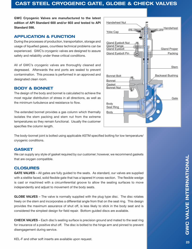
GWC Cryogenic Valves are manufactured to the latest
edition of API Standard 600 and/or 603 and tested to API
Standard 598.
aPPlication & functionDuring the processes of production, transportation, storage and
usage of liquefied gases, countless technical problems can be
experienced.GWC’scryogenicvalvesaredesignedtoassure
safety and reliability under these critical conditions.
All ofGWC’s cryogenic valves are thoroughly cleaned and
degreased. Afterwards the end ports are sealed to prevent
contamination. This process is performed in an approved and
designated clean room.
Body & BonnetThe design of the body and bonnet is calculated to achieve the
most regular distribution of stress in all directions, as well as
the minimum turbulence and resistance to flow.
The extended bonnet provides a gas column which thermally
isolates the stem packing and stem nut from the extreme
temperatures so they remain functional. Usually the customer
specifies the column length.
The body-bonnet joint is bolted using applicable ASTM specified bolting for low temperature/
cryogenic conditions.
gasKetWe can supply any style of gasket required by our customer; however, we recommend gaskets
that are oxygen compatible.
closuresGATE VALVES – All gates are fully guided to the seats. As standard, our valves are supplied
with a stellite faced, solid flexible gate that has a tapered H cross-section. The flexible wedge
is cast or machined with a circumferential groove to allow the seating surfaces to move
independently and adjust to movement of the body seats.
GLOBE VALVES – The valve is normally supplied with the plug type disc. The disc rotates
freely on the stem and incorporates a differential angle from that on the seat ring. This design
provides the maximum assurance of shut off, is less likely to stick in the body seat and is
considered the simplest design for field repair. Bottom guided discs are available.
CHECK VALVES–Eachdisc’sseatingsurfaceisprecisiongroundandmatedtotheseatring
for insurance of a positive shut off. The disc is bolted to the hinge arm and pinned to prevent
disengagement during service.
KEL-F and other soft inserts are available upon request.
cast steel cryogenic gate, gloBe & checK valves

gw
c v
alv
e i
nt
er
na
tio
na
l
24
cast steel cryogenic gate, gloBe & checK valves
seat ringStellite faced seat rings are standard and
provide excellent resistance to seizing and
galling. KEL-F inserts are available when
extremely tight shut-off is required. Our globe
and check valves are supplied with KEL-F or
other soft inserts as specified by the customer.
steMThe stem connection to the wedge is a T-head
design which is integral (without welding)
with the stem. The T-head on NPS 8” and
smaller valves are forged. The accuracy in
the dimensions and finishes assure a long life
with a perfect tightness in the packing area.
The stem-to-gate connection is designed to
prevent the turning or the disengagement
of stem from the wedge while the valve is in
service.
Through calculations and extreme testing, the
strength of the stem-to-gate connection has
proven to exceed the strength of the stem at
the root of its operating thread.
steM PacKingThe stem packing is designed and arranged to
ensure a maximum seal along the stem during
operation or while at position. Our packings
are NON-ASBESTOS types.
We can supply any style of packing required
by our customer.
steM nutThe stem nut arrangement and design allows
for the removal of the handwheel without
allowing the stem and gate to drop into the
closed position if the handwheel is removed
while the valve is in the open position.
Ball bearings are provided in the stem nut
arrangement of Class 150 valves from NPS
14”, on Class 300 valves from NPS 12”, on
Class 600 valves from NPS 6”, and on Class
900 and Class 1500 valves from NPS 2”.
PacKing glandThe packing gland design is a two-piece,
self-aligning type. The gland proper has a
spherical head that rides within spherical joint
of the gland flange. The gland proper has a
shoulder, which restricts the complete entry
into the stuffing box bore. This particular
design assures a straight compression of
the packing as the gland eyebolts are being
equally adjusted, without injuring the stem.
handwheelsHandwheels are designed for easy operation
and a comfortable grip. Our valves are
also available with gearing, motor actuators
or cylinder actuators for more demanding
services.
end connectionsOur standard production covers valves with:
• Flangeendswithraisedface(RF),flatface
(FF) or ring type joint (RTJ) ends that conform
to B16.5.
• Butt-welding(BW)endsthatconformto
B16.25.
• All face-to-face/end-to-end dimensions
conform to B16.10.
• Otherspecialendconnectionsaresupplied
accordingtocustomer’srequirements.
accessoriesAccessories such as gear operators, actuators,
bypasses, locking devices, chainwheels,
and many others are available to meet the
customers requirements.

gw
c v
alv
e i
nt
er
na
tio
na
l
25
Pressure-teMPerature ratings
cold worKing Pressure, psig
CLASS TEMP °FA216 WCB
A105 & LF2A352 LCC
A217 WC6
A182 F11
A217 WC9
A182 F22
A217 C5
A182 F5
A217 C12
A182 F9
A351 CF8
A182 F304
A351 CF8M
A182 F316A352 CN7M
150
-20 to 100 285 290 290 290 290 290 275 275 230
200 260 260 260 260 260 260 230 230 200
300 230 230 230 230 230 230 205 205 180
400 200 200 200 200 200 200 190 190 160
500 170 170 170 170 170 170 170 170 150
600 140 140 140 140 140 140 140 140 140
650 125 125 125 125 125 125 125 125
700 110 110 110 110 110 110 110 110
750 95 95 95 95 95 95 95 95
800 80 80 80 80 80 80 80 80
850 65 65 65 65 65 65 65 65
900 50 50 50 50 50 50 50 50
950 35 35 35 35 35 35 35 35
1000 20 20 20 20 20 20 20 20
1050 20 (a) 20 (a) 20 (a) 20 (a) 20(a) 20(a)
1100 20 (a) 20 (a) 20 (a) 20 (a) 20(a) 20(a)
1150 20 (a) 20 (a) 20 (a) 20 (a) 20(a) 20(a)
1200 15 (a) 15 (a) 15 (a) 20 (a) 20(a) 20(a)
1250 20(a) 20(a)
1300 20(a) 20(a)
1350 20(a) 20(a)
1400 20(a) 20(a)
1450 20(a) 20(a)
1500 15(a) 15(a)
asMe b16.34-2009
CLASS TEMP °FA216 WCB
A105 & LF2A352 LCC
A217 WC6
A182 F11
A217 WC9
A182 F22
A217 C5
A182 F5
A217 C12
A182 F9
A351 CF8
A182 F304
A351 CF8M
A182 F316A352 CN7M
300
-20 to 100 740 750 750 750 750 750 720 720 600
200 680 750 750 750 750 750 600 620 520
300 655 730 720 730 730 730 540 560 465
400 635 705 695 705 705 705 495 515 420
500 605 665 665 665 665 665 465 480 390
600 570 605 605 605 605 605 440 450 360
650 550 590 590 590 590 590 430 440
700 530 555 570 570 570 570 420 435
750 505 505 530 530 530 530 415 425
800 410 410 510 510 510 510 405 420
850 320 320 485 485 485 485 395 420
900 230 225 450 450 375 450 390 415
950 135 135 320 385 275 375 380 385
1000 85 85 215 265 200 255 355 365
1050 145 175 145 170 325 360
1100 95 110 100 115 255 305
1150 65 70 60 75 205 235
1200 40 40 35 50 165 185
1250 135 145
1300 115 115
1350 95 95
1400 75 75
1450 60 60
1500 40 40
(a) – Permissible, but not recommended for prolonged usage

gw
c v
alv
e i
nt
er
na
tio
na
l
26
Pressure-teMPerature ratings
asMe b16.34-2009
cold worKing Pressure, psig
CLASS TEMP °FA216 WCB
A105 & LF2A352 LCC
A217 WC6
A182 F11
A217 WC9
A182 F22
A217 C5
A182 F5
A217 C12
A182 F9
A351 CF8
A182 F304
A351 CF8M
A182 F316A352 CN7M
600
-20 to 100 1480 1500 1500 1500 1500 1500 1440 1440 1200
200 1360 1500 1500 1500 1500 1500 1200 1240 1035
300 1310 1455 1445 1455 1455 1455 1075 1120 930
400 1265 1405 1385 1410 1410 1410 995 1025 845
500 1205 1330 1330 1330 1330 1330 930 955 780
600 1135 1210 1210 1210 1210 1210 885 900 720
650 1100 1175 1175 1175 1175 1175 865 885
700 1060 1110 1135 1135 1135 1135 845 870
750 1015 1015 1065 1065 1065 1065 825 855
800 825 825 1015 1015 1015 1015 810 845
850 640 640 975 975 975 975 790 835
900 460 445 900 900 745 900 780 830
950 275 275 640 755 550 755 765 775
1000 170 170 430 535 400 505 710 725
1050 290 350 290 345 650 720
1100 190 220 200 225 515 610
1150 130 135 125 150 410 475
1200 80 80 70 105 330 370
1250 265 295
1300 225 235
1350 185 190
1400 150 150
1450 115 115
1500 85 85
CLASS TEMP °FA216 WCB
A105 & LF2A352 LCC
A217 WC6
A182 F11
A217 WC9
A182 F22
A217 C5
A182 F5
A217 C12
A182 F9
A351 CF8
A182 F304
A351 CF8M
A182 F316A352 CN7M
900
-20 to 100 2200 2250 2250 2250 2250 2250 2160 2160 1800
200 2035 2250 2250 2250 2250 2250 1800 1860 1555
300 1965 2185 2165 2185 2185 2185 1615 1680 1395
400 1900 2110 2080 2115 2115 2115 1490 1540 1265
500 1810 1995 1995 1995 1995 1995 1395 1435 1165
600 1705 1815 1815 1815 1815 1815 1325 1355 1080
650 1650 1765 1765 1765 1765 1765 1295 1325
700 1590 1665 1705 1705 1705 1705 1265 1305
750 1520 1520 1595 1595 1595 1595 1240 1280
800 1235 1235 1525 1525 1525 1525 1215 1265
850 955 955 1460 1460 1460 1460 1190 1255
900 690 670 1350 1350 1120 1350 1165 1245
950 410 410 955 1160 825 1130 1145 1160
1000 255 255 650 800 595 760 1065 1090
1050 430 525 430 515 975 1080
1100 290 330 300 340 770 915
1150 195 205 185 225 615 710
1200 125 125 105 155 495 555
1250 400 440
1300 340 350
1350 280 290
1400 225 225
1450 175 175
1500 125 125

gw
c v
alv
e i
nt
er
na
tio
na
l
27
cold worKing Pressure, psig
Pressure-teMPerature ratings
asMe b16.34-2009
CLASS TEMP °FA216 WCB
A105 & LF2A352 LCC
A217 WC6
A182 F11
A217 WC9
A182 F22
A217 C5
A182 F5
A217 C12
A182 F9
A351 CF8
A182 F304
A351 CF8M
A182 F316A352 CN7M
1500
-20 to 100 3705 3750 3750 3750 3750 3750 3600 3600 3000
200 3395 3750 3750 3750 3750 3750 3000 3095 3590
300 3270 3640 3610 3640 3640 3640 2690 2795 2330
400 3170 3520 3465 3530 3530 3530 2485 2570 2110
500 3015 3325 3325 3325 3325 3325 2330 2390 1945
600 2840 3025 3025 3025 3025 3025 2210 2255 1800
650 2745 2940 2940 2940 2940 2940 2160 2210
700 2665 2775 2840 2840 2840 2840 2110 2170
750 2535 2535 2660 2660 2660 2660 2065 2135
800 2055 2055 2540 2540 2540 2540 2030 2110
850 1595 1595 2435 2435 2435 2435 1980 2090
900 1150 1115 2245 2245 1870 2245 1945 2075
950 685 685 1595 1930 1370 1885 1910 1930
1000 430 430 1080 1335 995 1270 1770 1820
1050 720 875 720 855 1630 1800
1100 480 550 495 565 1285 1525
1150 325 345 310 375 1030 1185
1200 205 205 170 255 825 925
1250 670 735
1300 565 585
1350 465 480
1400 380 380
1450 290 290
1500 205 205
CLASS TEMP °FA216 WCB
A105 & LF2A352 LCC
A217 WC6
A182 F11
A217 WC9
A182 F22
A217 C5
A182 F5
A217 C12
A182 F9
A351 CF8
A182 F304
A351 CF8M
A182 F316A352 CN7M
2500
-20 to 100 6170 6250 6250 6250 6250 6250 6000 6000 5000
200 5655 6250 6250 6250 6250 6250 5000 5160 4320
300 5450 6070 6015 6070 6070 6070 4480 4660 3880
400 2280 5865 5775 5880 5880 5880 4140 4280 3520
500 5025 5540 5540 5540 5540 5540 3880 3980 3240
600 4730 5040 5040 5040 5040 5040 3680 3760 3000
650 4575 4905 4905 4905 4905 4905 3600 3680
700 4425 4630 4730 4730 4730 4730 3520 3620
750 4230 4230 4430 4430 4430 4430 3440 3560
800 3430 3430 4230 4230 4230 4230 3380 3520
850 2655 2655 4060 4060 4060 4060 3300 3480
900 1915 1855 3745 3745 3115 3745 3240 3460
950 1145 1145 2655 3220 2285 3145 3180 3220
1000 715 715 1800 2230 1655 2115 2950 3030
1050 1200 1455 1200 1430 2715 3000
1100 800 915 830 945 2145 2545
1150 545 570 515 630 1715 1970
1200 345 345 285 430 1370 1545
1250 1115 1230
1300 945 970
1350 770 800
1400 630 630
1450 485 485
1500 345 345

gw
c v
alv
e i
nt
er
na
tio
na
l
28
terMs & conditions of sale
scopeThese terms and conditions apply to all GWC valve products, and supersedes all previously published terms and conditions.
Hereafter, GWC Valve International, Inc. shall be referred to as GWC.
Specialtermsandconditionsprintedonabuyer’sorder will only apply insofar as they conform to the terms and conditions detailed on these pages. Terms and conditions of an order that change or modify those on this sheet shall not be binding on GWC.
approvalAll quotations, contracts, orders, or agreements are subject to approval and/or acceptance by the main office of GWC.
We reserve the right to correct clerical or stenographic errors in quotations, orders, invoices, and other contracts, agreements, or documents.
PricesPossession of price lists will not be accepted by GWC as an obligation, or offer to sell the goods listed therein to anyone.
All prices contained therein are subject to change without notice, and supersede all previous lists. All orders will be invoiced at prices in effect at the time of shipment unless quoted in writing.
changesOrders cannot be cancelled or specifications be changed without the consent of GWC, and then only in terms indemnifying GWC against loss.
QuotationsGoods quoted F.O.B. our service center are subject to prior sale. Prices quoted are valid only for the duration indicated in the quotation. Quoted prices supersede all previous prices, quotations, or contracts, and are subject to change without notice.
cancellationsOrders placed with us cannot be cancelled without our prior written consent. A cancellation charge will be applicable as outlined in our quotation.
claimsAll claims for shortages, corrections, or deductions must be made within 10 days after receipt of goods. Responsibility for goods lost or damaged in transit rests with carrier, and claims should be filed with the carrier by the consignee. Delivery of material to a common carrier shall be considered delivery to the buyer, and shall be at the buyers risk thereafter.
delivery delaysWe assume no responsibility for delays in delivery, or defaults resulting from strikes, work stoppages, fires, floods, accidents, war, inability to obtain materials, or any other cause unavoidable and beyond our control.
taxesGWC quotations and/or contracts do not include any municipal, state, or federal sales, excise, use occupational, or other taxes, and any such tax, if paid by us will be charged to the purchaser.
catalog illustrationsCatalog illustrations are actual representations of a certain size of each product line, but do not necessarily represent all sizes in details. We reserve the right to institute changes in materials, designs, and specifications without notice in keeping with our policy of continuing product improvement.
catalog weightsCatalog weights represent average weights of products and are in no sense guaranteed.
returnsSee Return Goods Policy on next page.
special ordersOrders for special goods must be in writing and accompanied with detailed prints and/or sets of specifications, unless specifications on the orders are definite and complete. Orders will not be entered with the factory unless this is adhered to. Cancellation charges will be as outlined in our quotations.
freight termsAll shipments are F.O.B. our service centers. See current bulletin for freight allowance.
warrantySee warranty on reverse side

gw
c v
alv
e i
nt
er
na
tio
na
l
29
This policy supersedes all other policies for return goods.
I. Goods returned at customers request:A. Material must be:1. Of our manufacture.2. In clean, new and saleable condition. It must have been stored inside out of the weather.3. Shipped from one of our service centers within the 12 calendar months preceding the request for return, and the return will not cause inventory to exceed maximum allowable levels.4. Personally inspected by a GWC representative prior to its return.5. Special or non-standard items are non-returnable.B. Return shipments must be prepaid.C. Credit will be allowed at invoice price, less 25% handling cost, and less any freight paid by GWC.D. A Return Goods Card must be furnished by a GWC representative after inspection of the material, and must be returned with the shipment.E. Shipments received without a Return Goods Authorization Card will be refused. Customer will be responsible for any storage and/or return freight.F. Material returned which is not of GWC manufacture, not in clean and saleable condition, or not authorized for return will be returned to the customer freight collect. II. Goods returned because of an error by GWC.A. Material must be in a clean, new, saleable condition.B. Return shipment should be made freight collect.C. Full credit will be allowed. D. Customer must receive Return Goods authorization prior to the return of the material. Return Goods Authorization Card must accompany shipment. Shipments received without Return Goods Authorization Card will be refused. Return Goods Authorization Card should be attached to the packing list.
All requests to return material to GWC Valve International, Inc. must be submitted in writing to our National Sales Manager for authorization.
GWC Valve International, Inc. warrants each product sold, if the products are of our manufacture, against defects in material and workmanship under normal use and service for a period of one year after date of shipment.
This warranty is made to the buyer only, and does not extend to any other party. The obligation of GWC Valve International, Inc. under this warranty is limited to: (a) replacement of any part or parts proven defective in material or workmanship, (b) repair of the product F.O.B. the factory or service center, (c) refund of the purchaseprice.InthecaseofproductorpartsnotwhollyofGWC’smanufacture,GWC’sliabilityunderthiswarrantyshallbelimitedtotheextentofGWC’srecoveryfromthemanufacturerofsuchpartsunderitswarranty to GWC. This warranty does not extend to any claims for labor, consequential damages, down time, or any other loss, damage, or expense of any kind arising out of the defect. We do not allow claims for unauthorized repairs, labor, or material. We are not responsible for loss of use, personal injury, lost profits, or any other damages whatsoever in connection with the warranties set forth.
No warranty shall apply to any product which has been modified or changed in design or function after leaving GWC’sfacilitiesorwhichismisusedoroperatedbeyonditsdesigncapabilities,orusedforotherthanitsintended purpose. Purchasers of GWC products should consult knowledgeable advisors in the selection of product type and material of construction for their specific use. The buyer assumes all risk of this selection.
The buyer shall permit GWC or its authorized representative to inspect the product so that it may determine its obligation. GWC shall be entitled to the return of the defective product or parts. Buyer must notify GWC promptly upon discover of any claimed defect.
No material may be returned without first obtaining written permission from GWC Valve International, Inc.
return goods Policy
warranty

gw
c v
alv
e i
nt
er
na
tio
na
l
30
notes


catalog nuMBer csv-1003
Usa headQUarters
gwc valve international, inc.
4301 yeager way
Bakersfield, ca 93313
Ph: 1-661-834-1775
fax: 1-661-834-2072
e-Mail: [email protected]
www.gwcvalve.com