Gutor PXC
25-100 kVA
Operation
03/2018
www.schneider-electric.com
Legal InformationThe Schneider Electric brand and any registered trademarks of Schneider ElectricIndustries SAS referred to in this guide are the sole property of Schneider ElectricSA and its subsidiaries. They may not be used for any purpose without the owner'spermission, given in writing. This guide and its content are protected, within themeaning of the French intellectual property code (Code de la propriétéintellectuelle français, referred to hereafter as "the Code"), under the laws ofcopyright covering texts, drawings and models, as well as by trademark law. Youagree not to reproduce, other than for your own personal, noncommercial use asdefined in the Code, all or part of this guide on any medium whatsoever withoutSchneider Electric's permission, given in writing. You also agree not to establishany hypertext links to this guide or its content. Schneider Electric does not grantany right or license for the personal and noncommercial use of the guide or itscontent, except for a non-exclusive license to consult it on an "as is" basis, at yourown risk. All other rights are reserved.
Electrical equipment should be installed, operated, serviced, and maintained onlyby qualified personnel. No responsibility is assumed by Schneider Electric for anyconsequences arising out of the use of this material.
As standards, specifications, and designs change from time to time, please ask forconfirmation of the information given in this publication.
25-100 kVA
Table of Contents
Important Safety Instructions — SAVE THESEINSTRUCTIONS.........................................................................................5
FCC Statement ..........................................................................................6Safety Precautions .....................................................................................6
Overview ......................................................................................................9UPS without Transformer ............................................................................9
System Overview..................................................................................9UPS with Transformer............................................................................... 11
System Overview................................................................................ 11User Interface ..........................................................................................15
Display...............................................................................................18View System Status ............................................................................20View System Configuration..................................................................21
Operation ...................................................................................................23Operation Modes......................................................................................23Operation Procedures...............................................................................25
Turn on the UPS .................................................................................25Turn off the UPS .................................................................................25Transfer from Normal Operation to ECO Mode......................................25Transfer from ECO Mode to Normal Operation ......................................25Transfer from Normal Operation to Requested Static BypassOperation ...........................................................................................25Transfer from Requested Static Bypass Operation to NormalOperation ...........................................................................................26Transfer from Normal Operation to Maintenance BypassOperation ...........................................................................................26Transfer from Maintenance Bypass Operation to NormalOperation ...........................................................................................27Transfer from Normal Operation or ECO Mode to MaintenanceBypass Operation – Redundant Parallel UPS System N+1.....................29Transfer from Maintenance Bypass Operation to Normal Operation orECO Mode – Redundant Parallel UPS System N+1...............................30View the Event Log .............................................................................31Clear the Event Log ............................................................................31View the Alarms..................................................................................31View Diagnosis ...................................................................................32View Statistics ....................................................................................33Clear Statistics ...................................................................................33
Configuration .............................................................................................34Set the Date and Time ..............................................................................34Set Up the Display ....................................................................................34Reset the Display Language to English ......................................................35Set Auto Start, Auto Boost, LCM Alerts, and ECO Mode..........................35Set Battery Charge Mode ..........................................................................36
Maintenance ..............................................................................................37Replace the Filters....................................................................................37Perform LED and Display Test ...................................................................37
990–9969B–001 3
25-100 kVA
Perform Advanced Battery Monitoring (ABM) Test.......................................37Perform Discharge Test.............................................................................38Life Cycle Monitoring (LCM) ......................................................................39
Troubleshooting ........................................................................................40Log Events...............................................................................................42Alarm LEDs..............................................................................................47Input Contacts and Output Relays..............................................................48
4 990–9969B–001
Important Safety Instructions — SAVE THESEINSTRUCTIONS 25-100 kVA
Important Safety Instructions — SAVE THESEINSTRUCTIONS
Read these instructions carefully and look at the equipment to become familiar withit before trying to install, operate, service or maintain it. The following safetymessages may appear throughout this manual or on the equipment to warn ofpotential hazards or to call attention to information that clarifies or simplifies aprocedure.
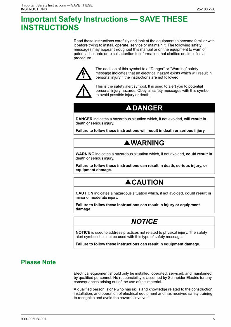
The addition of this symbol to a “Danger” or “Warning” safetymessage indicates that an electrical hazard exists which will result inpersonal injury if the instructions are not followed.
This is the safety alert symbol. It is used to alert you to potentialpersonal injury hazards. Obey all safety messages with this symbolto avoid possible injury or death.
DANGERDANGER indicates a hazardous situation which, if not avoided, will result indeath or serious injury.
Failure to follow these instructions will result in death or serious injury.
WARNINGWARNING indicates a hazardous situation which, if not avoided, could result indeath or serious injury.
Failure to follow these instructions can result in death, serious injury, orequipment damage.
CAUTIONCAUTION indicates a hazardous situation which, if not avoided, could result inminor or moderate injury.
Failure to follow these instructions can result in injury or equipmentdamage.
NOTICENOTICE is used to address practices not related to physical injury. The safetyalert symbol shall not be used with this type of safety message.
Failure to follow these instructions can result in equipment damage.
Please NoteElectrical equipment should only be installed, operated, serviced, and maintainedby qualified personnel. No responsibility is assumed by Schneider Electric for anyconsequences arising out of the use of this material.
A qualified person is one who has skills and knowledge related to the construction,installation, and operation of electrical equipment and has received safety trainingto recognize and avoid the hazards involved.
990–9969B–001 5
25-100 kVAImportant Safety Instructions — SAVE THESE
INSTRUCTIONS
FCC StatementNOTE: This equipment has been tested and found to comply with the limits fora Class A digital device, pursuant to Part 15 of the FCC Rules. These limits aredesigned to provide reasonable protection against harmful interference whenthe equipment is operated in a commercial environment. This equipmentgenerates, uses, and can radiate radio frequency energy and, if not installedand used in accordance with the instruction manual, may cause harmfulinterference to radio communications. Operation of this equipment in aresidential area is likely to cause harmful interference in which case the userwill be required to correct the interference at his own expense.
Any changes or modifications not expressly approved by the party responsible forcompliance could void the user’s authority to operate the equipment.
Safety Precautions
DANGERHAZARD OF ELECTRIC SHOCK, EXPLOSION, OR ARC FLASH
All safety instructions in this document must be read, understood and followed.
Failure to follow these instructions will result in death or serious injury.
DANGERHAZARD OF ELECTRIC SHOCK, EXPLOSION, OR ARC FLASH
Read all instructions in the Installation Manual before installing or working on thisUPS system.
Failure to follow these instructions will result in death or serious injury.
DANGERHAZARD OF ELECTRIC SHOCK, EXPLOSION, OR ARC FLASH
Do not install the UPS system until all construction work has been completedand the installation room has been cleaned.
Failure to follow these instructions will result in death or serious injury.
DANGERHAZARD OF ELECTRIC SHOCK, EXPLOSION, OR ARC FLASH• The product must be installed according to the specifications and
requirements as defined by Schneider Electric. It concerns in particular theexternal and internal protections (upstream breakers, battery breakers,cabling, etc.) and environmental requirements. No responsibility is assumedby Schneider Electric if these requirements are not respected.
• After the UPS system has been electrically wired, do not start up the system.Start-up must only be performed by Schneider Electric.
Failure to follow these instructions will result in death or serious injury.
6 990–9969B–001
Important Safety Instructions — SAVE THESEINSTRUCTIONS 25-100 kVA
DANGERHAZARD OF ELECTRIC SHOCK, EXPLOSION, OR ARC FLASH
The UPS system must be installed according to local and national regulations.Install the UPS according to:• IEC 60364 (including 60364–4–41- protection against electric shock, 60364–
4–42 - protection against thermal effect, and 60364–4–43 - protection againstovercurrent), or
• NEC NFPA 70, or• Canadian Electrical Code (C22.1, Part 1)depending on which one of the standards apply in your local area.
Failure to follow these instructions will result in death or serious injury.
DANGERHAZARD OF ELECTRIC SHOCK, EXPLOSION, OR ARC FLASH• Install the UPS system in a temperature controlled indoor environment free of
conductive contaminants and humidity.• Install the UPS system on a non-flammable, level and solid surface (e.g.
concrete) that can support the weight of the system.Failure to follow these instructions will result in death or serious injury.
DANGERHAZARD OF ELECTRIC SHOCK, EXPLOSION, OR ARC FLASH
The UPS is not designed for and must therefore not be installed in the followingunusual operating environments:• Damaging fumes• Explosive mixtures of dust or gases, corrosive gases, or conductive or radiant
heat from other sources• Moisture, abrasive dust, steam or in an excessively damp environment• Fungus, insects, vermin• Salt-laden air or contaminated cooling refrigerant• Pollution degree higher than 2 according to IEC 60664-1• Exposure to abnormal vibrations, shocks, and tilting• Exposure to direct sunlight, heat sources, or strong electromagnetic fieldsFailure to follow these instructions will result in death or serious injury.
DANGERHAZARD OF ELECTRIC SHOCK, EXPLOSION, OR ARC FLASH
Do not drill or cut holes for cables or conduits with the gland plates installed anddo not drill or cut holes in close proximity to the UPS.
Failure to follow these instructions will result in death or serious injury.
WARNINGHAZARD OFARC FLASH
Do not make mechanical changes to the product (including removal of cabinetparts or drilling/cutting of holes) that are not described in the Installation Manual.
Failure to follow these instructions can result in death, serious injury, orequipment damage.
990–9969B–001 7
25-100 kVAImportant Safety Instructions — SAVE THESE
INSTRUCTIONS
NOTICERISK OF OVERHEATING
Respect the space requirements around the UPS system and do not cover theproduct’s ventilation openings when the UPS system is in operation.
Failure to follow these instructions can result in equipment damage.
NOTICERISK OF EQUIPMENT DAMAGE
Do not connect the UPS output to regenerative load systems includingphotovoltaic systems and speed drives.
Failure to follow these instructions can result in equipment damage.
8 990–9969B–001
Overview 25-100 kVA
Overview
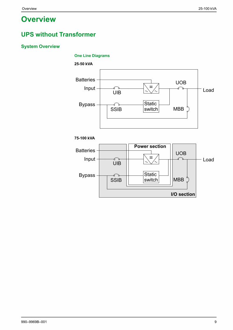
UPS without Transformer
System Overview
One Line Diagrams
25-50 kVA
75-100 kVA
990–9969B–001 9
25-100 kVA Overview
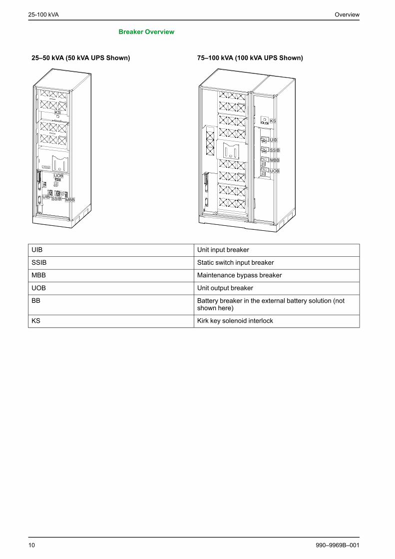
Breaker Overview
25–50 kVA (50 kVA UPS Shown) 75–100 kVA (100 kVA UPS Shown)
UIB Unit input breaker
SSIB Static switch input breaker
MBB Maintenance bypass breaker
UOB Unit output breaker
BB Battery breaker in the external battery solution (notshown here)
KS Kirk key solenoid interlock
10 990–9969B–001
Overview 25-100 kVA
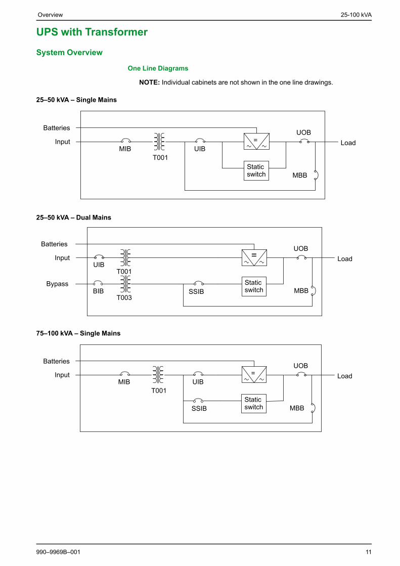
UPS with Transformer
System Overview
One Line Diagrams
NOTE: Individual cabinets are not shown in the one line drawings.
25–50 kVA – Single Mains
25–50 kVA – Dual Mains
75–100 kVA – Single Mains
990–9969B–001 11
25-100 kVA Overview
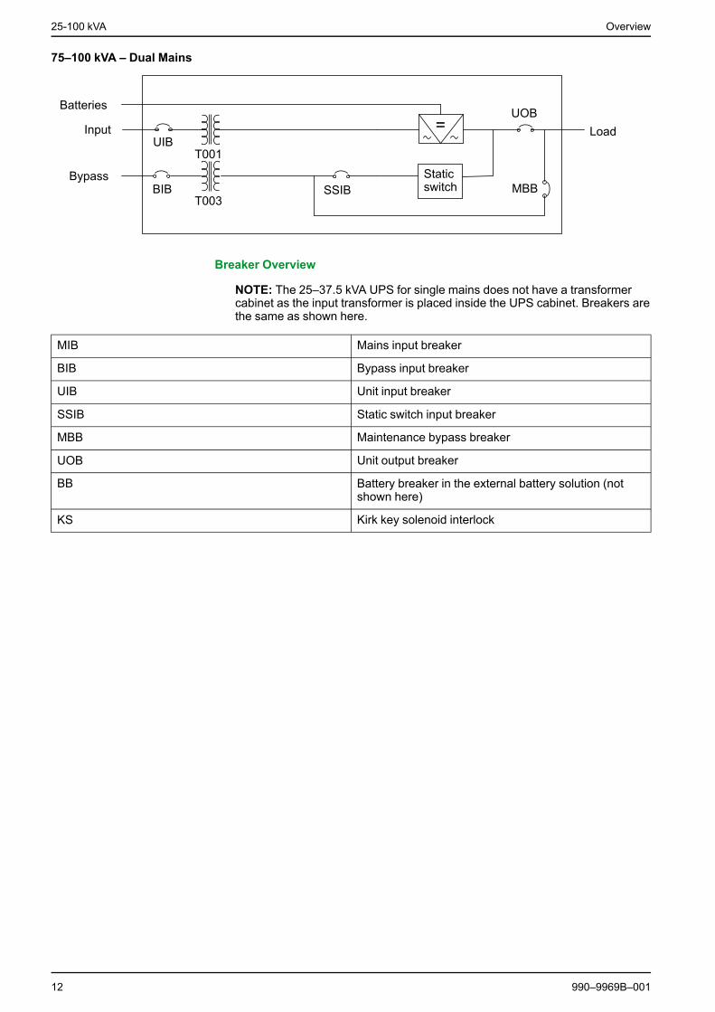
75–100 kVA – Dual Mains
Breaker Overview
NOTE: The 25–37.5 kVA UPS for single mains does not have a transformercabinet as the input transformer is placed inside the UPS cabinet. Breakers arethe same as shown here.
MIB Mains input breaker
BIB Bypass input breaker
UIB Unit input breaker
SSIB Static switch input breaker
MBB Maintenance bypass breaker
UOB Unit output breaker
BB Battery breaker in the external battery solution (notshown here)
KS Kirk key solenoid interlock
12 990–9969B–001
Overview 25-100 kVA
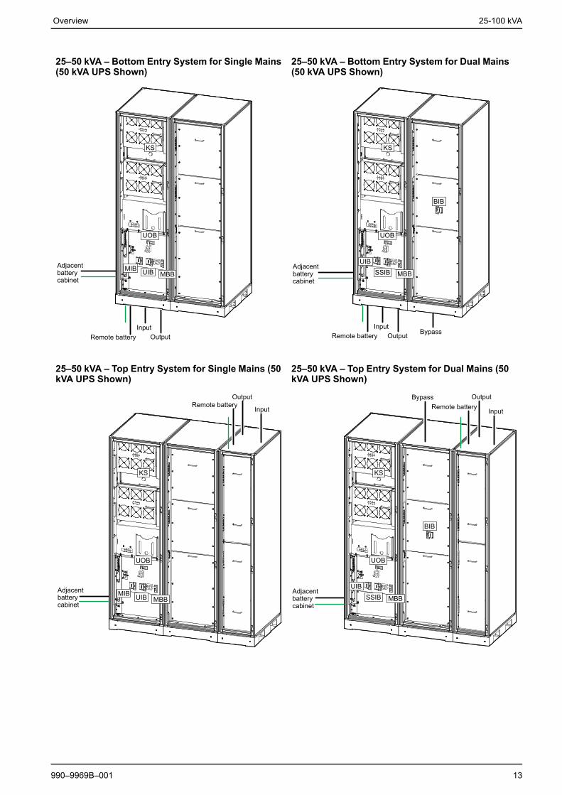
25–50 kVA – Bottom Entry System for Single Mains(50 kVA UPS Shown)
25–50 kVA – Bottom Entry System for Dual Mains(50 kVA UPS Shown)
25–50 kVA – Top Entry System for Single Mains (50kVA UPS Shown)
25–50 kVA – Top Entry System for Dual Mains (50kVA UPS Shown)
990–9969B–001 13
25-100 kVA Overview
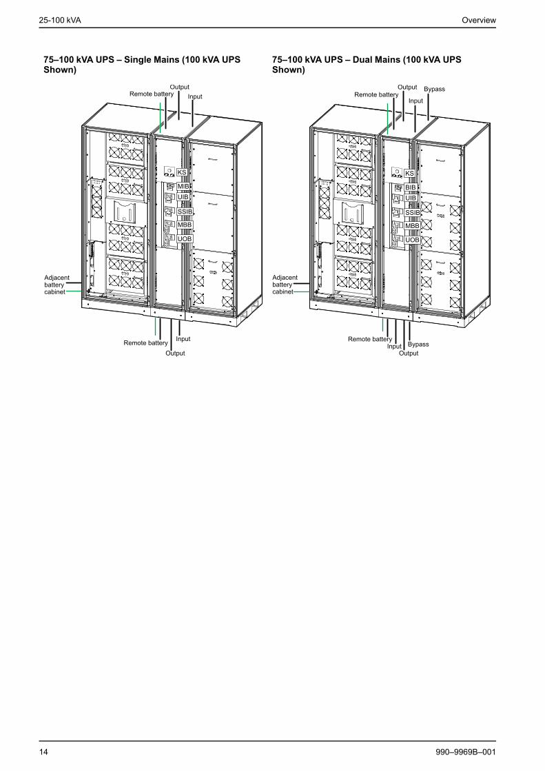
75–100 kVA UPS – Single Mains (100 kVA UPSShown)
75–100 kVA UPS – Dual Mains (100 kVA UPSShown)
14 990–9969B–001
Overview 25-100 kVA
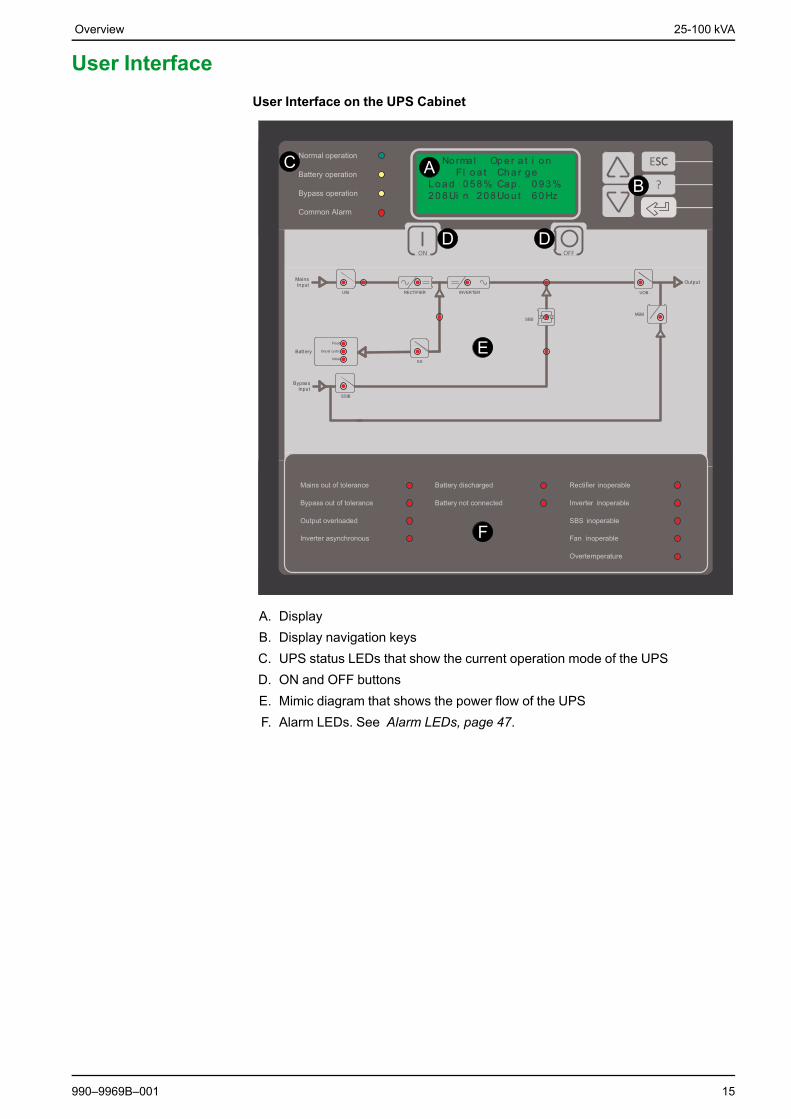
User InterfaceUser Interface on the UPS Cabinet
A. DisplayB. Display navigation keysC. UPS status LEDs that show the current operation mode of the UPSD. ON and OFF buttonsE. Mimic diagram that shows the power flow of the UPSF. Alarm LEDs. See Alarm LEDs, page 47.
990–9969B–001 15
25-100 kVA Overview
Display Navigation Keys
Use the ENTER key to enter the main menu, submenus, and confirm/save settings.
Use the ESC key to return to a higher level menu.
Use the UP key to select a submenu or to change a setting upwards.
Use the DOWN key to select a submenu or to change a setting downwards.
Use the HELP key to access help information about a menu point.
UPS Status LEDs
Normal operation LED Green The load is supplied by the input source.
Battery operation LED Yellow The load is supplied by the batteries.
Bypass operation LED Yellow The load is supplied by the bypass source.
Common Alarm LED Red An alarm exists in the UPS system.
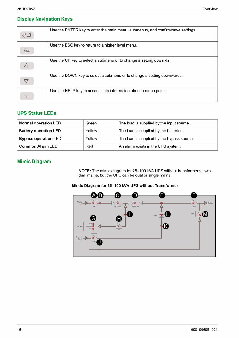
Mimic Diagram
NOTE: The mimic diagram for 25–100 kVA UPS without transformer showsdual mains, but the UPS can be dual or single mains.
Mimic Diagram for 25–100 kVA UPS without Transformer
16 990–9969B–001
Overview 25-100 kVA
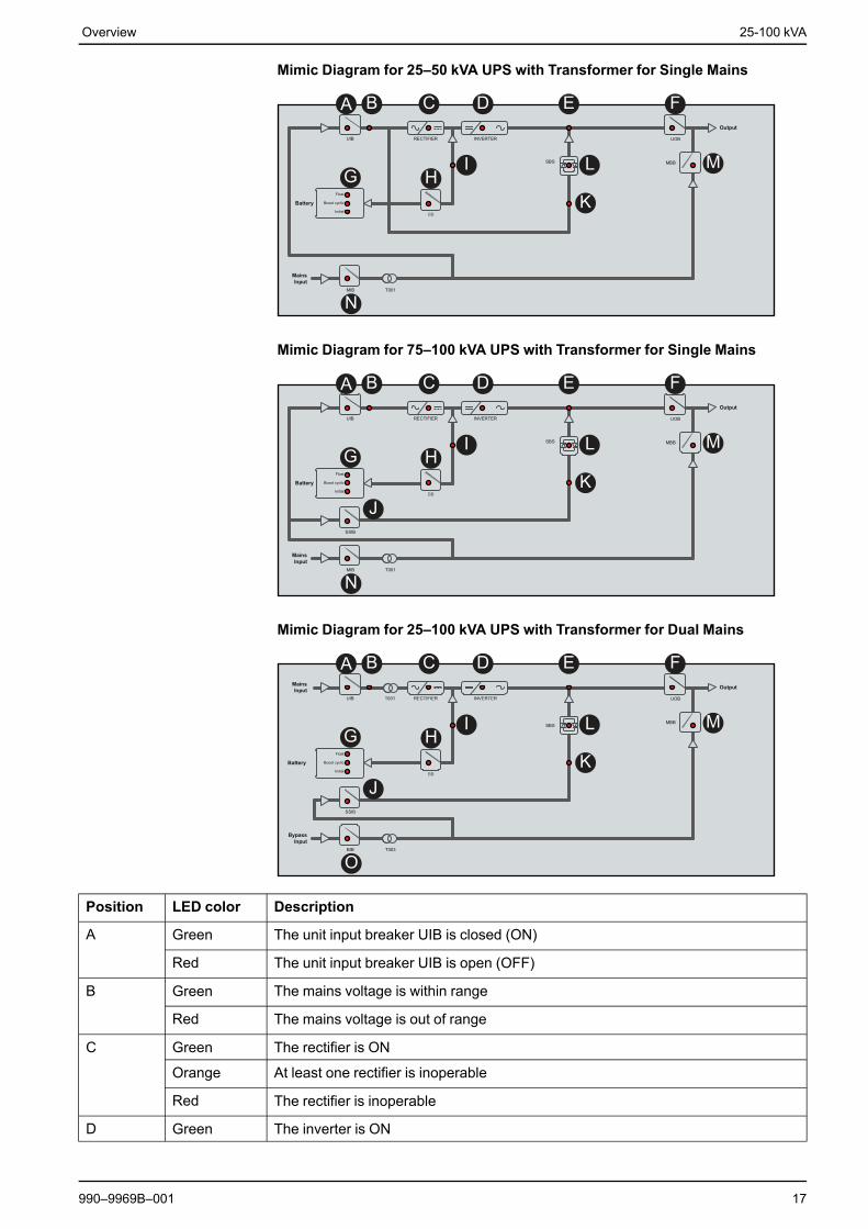
Mimic Diagram for 25–50 kVA UPS with Transformer for Single Mains
MainsInput
Output
UIB
MIB
BB
Battery
UOBRECTIFIER INVERTER
T001
SBS
Float
Boost cyclic
Initial
MBB
A B C D E F
L
K
MIHG
N
Mimic Diagram for 75–100 kVA UPS with Transformer for Single Mains
MainsInput
Output
UIB
SSIB
MIB
BB
Battery
UOBRECTIFIER INVERTER
T001
SBS
Float
Boost cyclic
Initial
MBB
A B C D E F
L
K
MIHG
N
J
Mimic Diagram for 25–100 kVA UPS with Transformer for Dual Mains
BypassInput
Output
UIB
SSIB
BIB
BB
Battery
UOBRECTIFIER INVERTERT001
T003
SBS
Float
Boost cyclic
Initial
MBB
MainsInput
A B C D E F
L
K
MIHG
O
J
Position LED color Description
A Green The unit input breaker UIB is closed (ON)
Red The unit input breaker UIB is open (OFF)
B Green The mains voltage is within range
Red The mains voltage is out of range
C Green The rectifier is ON
Orange At least one rectifier is inoperable
Red The rectifier is inoperable
D Green The inverter is ON
990–9969B–001 17
25-100 kVA Overview
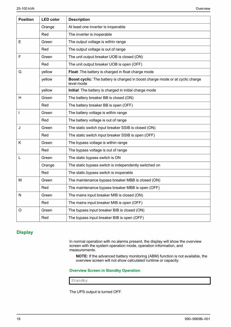
Position LED color Description
Orange At least one inverter is inoperable
Red The inverter is inoperable
E Green The output voltage is within range
Red The output voltage is out of range
F Green The unit output breaker UOB is closed (ON)
Red The unit output breaker UOB is open (OFF)
G yellow Float: The battery is charged in float charge mode
yellow Boost cyclic: The battery is charged in boost charge mode or at cyclic chargelevel mode
yellow Initial: The battery is charged in initial charge mode
H Green The battery breaker BB is closed (ON)
Red The battery breaker BB is open (OFF)
I Green The battery voltage is within range
Red The battery voltage is out of range
J Green The static switch input breaker SSIB is closed (ON)
Red The static switch input breaker SSIB is open (OFF)
K Green The bypass voltage is within range
Red The bypass voltage is out of range
L Green The static bypass switch is ON
Orange The static bypass switch is independently switched on
Red The static bypass switch is inoperable
M Green The maintenance bypass breaker MBB is closed (ON)
Red The maintenance bypass breaker MBB is open (OFF)
N Green The mains input breaker MIB is closed (ON)
Red The mains input breaker MIB is open (OFF)
O Green The bypass input breaker BIB is closed (ON)
Red The bypass input breaker BIB is open (OFF)
Display
In normal operation with no alarms present, the display will show the overviewscreen with the system operation mode, operation information, andmeasurements.
NOTE: If the advanced battery monitoring (ABM) function is not available, theoverview screen will not show calculated runtime or capacity.
Overview Screen in Standby Operation
Standby
The UPS output is turned OFF.
18 990–9969B–001
Overview 25-100 kVA
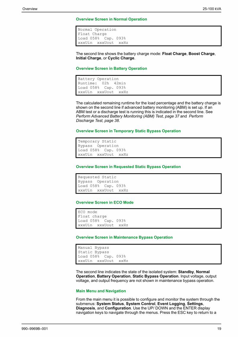
Overview Screen in Normal Operation
Normal OperationFloat ChargeLoad 058% Cap. 093%xxxUin xxxUout xxHz
The second line shows the battery charge mode: Float Charge, Boost Charge,Initial Charge, or Cyclic Charge.
Overview Screen in Battery Operation
Battery OperationRuntime: 02h 42minLoad 058% Cap. 093%xxxUin xxxUout xxHz
The calculated remaining runtime for the load percentage and the battery charge isshown on the second line if advanced battery monitoring (ABM) is set up. If anABM test or a discharge test is running this is indicated in the second line. SeePerform Advanced Battery Monitoring (ABM) Test, page 37 and PerformDischarge Test, page 38.
Overview Screen in Temporary Static Bypass Operation
Temporary StaticBypass OperationLoad 058% Cap. 093%xxxUin xxxUout xxHz
Overview Screen in Requested Static Bypass Operation
Requested StaticBypass OperationLoad 058% Cap. 093%xxxUin xxxUout xxHz
Overview Screen in ECO Mode
ECO modeFloat chargeLoad 058% Cap. 093%xxxUin xxxUout xxHz
Overview Screen in Maintenance Bypass Operation
Manual BypassStatic BypassLoad 058% Cap. 093%xxxUin xxxUout xxHz
The second line indicates the state of the isolated system: Standby, NormalOperation, Battery Operation, Static Bypass Operation. Input voltage, outputvoltage, and output frequency are not shown in maintenance bypass operation.
Main Menu and Navigation
From the main menu it is possible to configure and monitor the system through thesubmenus: System Status, System Control, Event Logging, Settings,Diagnosis, and Configuration. Use the UP/ DOWN and the ENTER displaynavigation keys to navigate through the menus. Press the ESC key to return to a
990–9969B–001 19
25-100 kVA Overview
previous menu. Press the HELP key to access help information about a menupoint.
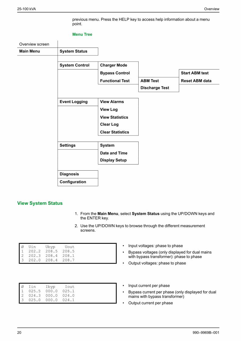
Menu Tree
Overview screen
Main Menu System Status
System Control Charger Mode
Bypass Control Start ABM test
Functional Test ABM Test Reset ABM dataDischarge Test
Event Logging View Alarms
View Log
View StatisticsClear Log
Clear Statistics
Settings System
Date and TimeDisplay Setup
Diagnosis
Configuration
View System Status
1. From theMain Menu, select System Status using the UP/DOWN keys andthe ENTER key.
2. Use the UP/DOWN keys to browse through the different measurementscreens.
Ø Uin Ubyp Uout1 202.2 208.5 208.52 202.3 208.4 208.13 202.0 208.4 208.7
• Input voltages: phase to phase• Bypass voltages (only displayed for dual mains
with bypass transformer): phase to phase• Output voltages: phase to phase
Ø Iin Ibyp Iout1 025.5 000.0 025.12 024.3 000.0 024.03 025.0 000.0 024.1
• Input current per phase• Bypass current per phase (only displayed for dual
mains with bypass transformer)• Output current per phase
20 990–9969B–001
Overview 25-100 kVA
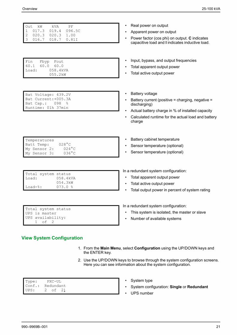
Out kW kVA PF1 017.3 019.4 096.5C2 020.3 020.3 1.003 016.7 018.7 0.81I
• Real power on output• Apparent power on output• Power factor (cos phi) on output. C indicates
capacitive load and I indicates inductive load.
Fin Fbyp Fout60.1 60.0 60.0Load: 058.4kVA
055.2kW
• Input, bypass, and output frequencies• Total apparent output power• Total active output power
Bat Voltage: 439.2VBat Current:+005.3ABat Cap.: 098 %Runtime: 01h 37min
• Battery voltage• Battery current (positive = charging, negative =
discharging)• Actual battery charge in % of installed capacity• Calculated runtime for the actual load and battery
charge
TemperaturesBatt Temp: 028°CMy Sensor 2: 024°CMy Sensor 3: 036°C
• Battery cabinet temperature• Sensor temperature (optional)• Sensor temperature (optional)
Total system statusLoad: 058.4kVA
054.3kWLoad-%: 073.0 %
In a redundant system configuration:• Total apparent output power• Total active output power• Total output power in percent of system rating
Total system statusUPS is masterUPS availability:
1 of 2
In a redundant system configuration:• This system is isolated, the master or slave• Number of available systems
View System Configuration
1. From theMain Menu, select Configuration using the UP/DOWN keys andthe ENTER key.
2. Use the UP/DOWN keys to browse through the system configuration screens.Here you can see information about the system configuration.
Type: PXC-ULConf.: RedundantUPS: 2 of 2↓
• System type• System configuration: Single or Redundant• UPS number
990–9969B–001 21
25-100 kVA Overview
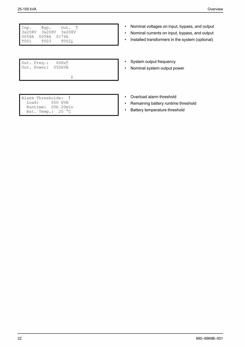
Inp. Byp. Out. ↑3x208V 3x208V 3x208V0058A 0058A 0174AT001 T003 T002↓
• Nominal voltages on input, bypass, and output• Nominal currents on input, bypass, and output• Installed transformers in the system (optional)
Out. Freq.: 60Hz↑Out. Power: 050kVA
↓
• System output frequency• Nominal system output power
Alarm Thresholds: ↑Load: 050 kVARuntime: 00h 20minBat. Temp.: 25 °C
• Overload alarm threshold• Remaining battery runtime threshold• Battery temperature threshold
22 990–9969B–001
Operation 25-100 kVA
Operation
Operation Modes
Normal Operation
During normal operation, the UPS supports the load with conditioned power. Whilethe UPS is in normal operation, the status LED Normal operation is green.
Battery Operation
If the utility/mains supply becomes unavailable or outside specified limits, the UPStransfers to battery operation and supports the load with conditioned power fromthe DC source. While the UPS system is in battery operation, the status LEDBattery operation is yellow.
Temporary Static Bypass Operation
The UPS is in temporary static bypass following a command from the UPS system.During temporary static bypass operation, the load is supplied by the bypasssource. If there is an interruption to the utility/mains power supply during temporarystatic bypass operation, the system will transfer to battery operation. The load mayexperience a short duration interruption of power (4 to 8 ms) during this transfer.While the UPS system is in temporary static bypass operation, the status LEDBypass operation is yellow.
Requested Static Bypass Operation
The UPS can be transferred to requested static bypass operation following acommand from the display. During static bypass operation, the load is suppliedfrom the bypass source. If there is an interruption to the utility/mains power supplyduring requested static bypass operation, the system will transfer to batteryoperation. The load may experience a short duration interruption of power (4 to 8ms) during this transfer. While the UPS system is in requested static bypass, thestatus LED Bypass operation is yellow.
ECO Mode
The UPS can be transferred to ECO mode with a command from the display orwhen ECO mode is enabled. The system will automatically switch to ECO modeafter the system has been running for one minute in normal operation and thebypass voltage quality is within the acceptable limits. ECO mode will transfer thesystem to static bypass operation. In this operation mode the total systemefficiency is increased. The load is supplied from the bypass source. To avoidinterruptions during the transfer, the voltage, frequency and phase relation of theUPS system must be synchronized to the bypass source. The UPS will transfer tonormal or battery operation if the bypass source becomes unavailable or if thebypass voltage quality drops below the acceptable limits. While the UPS system isin ECO mode, the status LED Bypass operation is yellow.
990–9969B–001 23
25-100 kVA Operation
Maintenance Bypass Operation
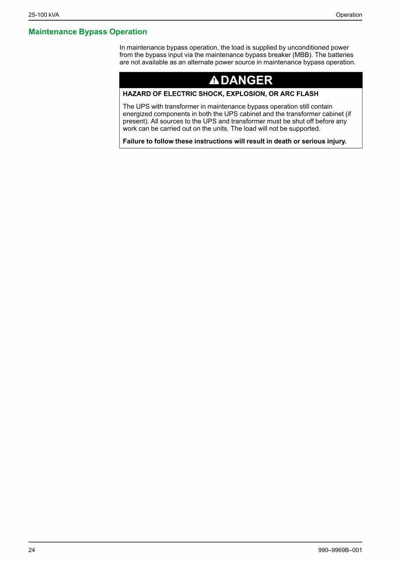
In maintenance bypass operation, the load is supplied by unconditioned powerfrom the bypass input via the maintenance bypass breaker (MBB). The batteriesare not available as an alternate power source in maintenance bypass operation.
DANGERHAZARD OF ELECTRIC SHOCK, EXPLOSION, OR ARC FLASH
The UPS with transformer in maintenance bypass operation still containenergized components in both the UPS cabinet and the transformer cabinet (ifpresent). All sources to the UPS and transformer must be shut off before anywork can be carried out on the units. The load will not be supported.
Failure to follow these instructions will result in death or serious injury.
24 990–9969B–001
Operation 25-100 kVA
Operation Procedures
Turn on the UPS
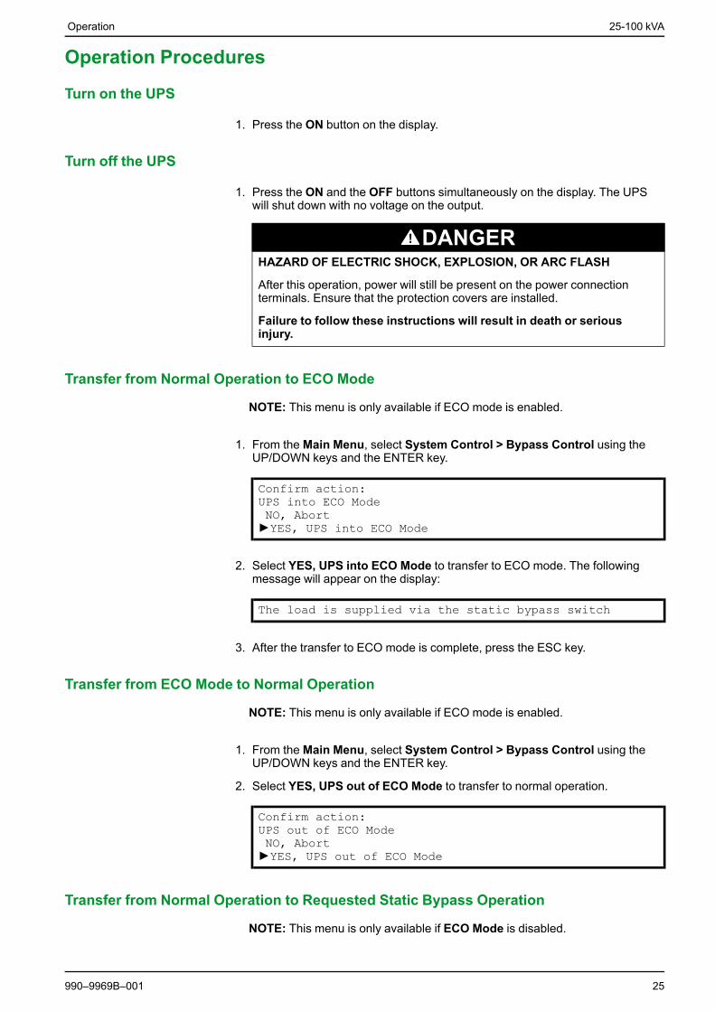
1. Press the ON button on the display.
Turn off the UPS
1. Press the ON and the OFF buttons simultaneously on the display. The UPSwill shut down with no voltage on the output.
DANGERHAZARD OF ELECTRIC SHOCK, EXPLOSION, OR ARC FLASH
After this operation, power will still be present on the power connectionterminals. Ensure that the protection covers are installed.
Failure to follow these instructions will result in death or seriousinjury.
Transfer from Normal Operation to ECO Mode
NOTE: This menu is only available if ECO mode is enabled.
1. From theMain Menu, select System Control > Bypass Control using theUP/DOWN keys and the ENTER key.
Confirm action:UPS into ECO ModeNO, Abort
►YES, UPS into ECO Mode
2. Select YES, UPS into ECO Mode to transfer to ECO mode. The followingmessage will appear on the display:
The load is supplied via the static bypass switch
3. After the transfer to ECO mode is complete, press the ESC key.
Transfer from ECO Mode to Normal Operation
NOTE: This menu is only available if ECO mode is enabled.
1. From theMain Menu, select System Control > Bypass Control using theUP/DOWN keys and the ENTER key.
2. Select YES, UPS out of ECO Mode to transfer to normal operation.
Confirm action:UPS out of ECO ModeNO, Abort
►YES, UPS out of ECO Mode
Transfer from Normal Operation to Requested Static Bypass Operation
NOTE: This menu is only available if ECO Mode is disabled.
990–9969B–001 25
25-100 kVA Operation
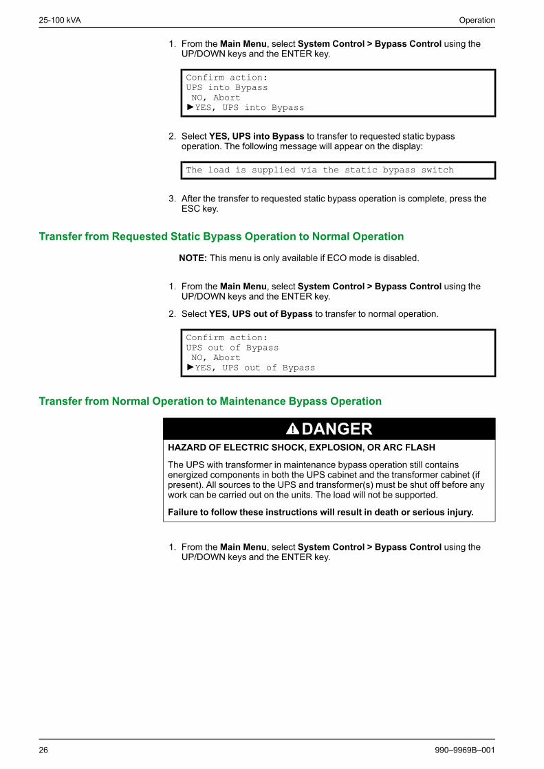
1. From theMain Menu, select System Control > Bypass Control using theUP/DOWN keys and the ENTER key.
Confirm action:UPS into BypassNO, Abort
►YES, UPS into Bypass
2. Select YES, UPS into Bypass to transfer to requested static bypassoperation. The following message will appear on the display:
The load is supplied via the static bypass switch
3. After the transfer to requested static bypass operation is complete, press theESC key.
Transfer from Requested Static Bypass Operation to Normal Operation
NOTE: This menu is only available if ECO mode is disabled.
1. From theMain Menu, select System Control > Bypass Control using theUP/DOWN keys and the ENTER key.
2. Select YES, UPS out of Bypass to transfer to normal operation.
Confirm action:UPS out of BypassNO, Abort
►YES, UPS out of Bypass
Transfer from Normal Operation to Maintenance Bypass Operation
DANGERHAZARD OF ELECTRIC SHOCK, EXPLOSION, OR ARC FLASH
The UPS with transformer in maintenance bypass operation still containsenergized components in both the UPS cabinet and the transformer cabinet (ifpresent). All sources to the UPS and transformer(s) must be shut off before anywork can be carried out on the units. The load will not be supported.
Failure to follow these instructions will result in death or serious injury.
1. From theMain Menu, select System Control > Bypass Control using theUP/DOWN keys and the ENTER key.
26 990–9969B–001
Operation 25-100 kVA
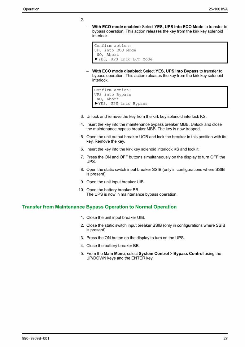
2.
– With ECO mode enabled: Select YES, UPS into ECO Mode to transfer tobypass operation. This action releases the key from the kirk key solenoidinterlock.
Confirm action:UPS into ECO ModeNO, Abort
►YES, UPS into ECO Mode
– With ECO mode disabled: Select YES, UPS into Bypass to transfer tobypass operation. This action releases the key from the kirk key solenoidinterlock.
Confirm action:UPS into BypassNO, Abort
►YES, UPS into Bypass
3. Unlock and remove the key from the kirk key solenoid interlock KS.
4. Insert the key into the maintenance bypass breaker MBB. Unlock and closethe maintenance bypass breaker MBB. The key is now trapped.
5. Open the unit output breaker UOB and lock the breaker in this position with itskey. Remove the key.
6. Insert the key into the kirk key solenoid interlock KS and lock it.
7. Press the ON and OFF buttons simultaneously on the display to turn OFF theUPS.
8. Open the static switch input breaker SSIB (only in configurations where SSIBis present).
9. Open the unit input breaker UIB.
10. Open the battery breaker BB.The UPS is now in maintenance bypass operation.
Transfer from Maintenance Bypass Operation to Normal Operation
1. Close the unit input breaker UIB.
2. Close the static switch input breaker SSIB (only in configurations where SSIBis present).
3. Press the ON button on the display to turn on the UPS.
4. Close the battery breaker BB.
5. From theMain Menu, select System Control > Bypass Control using theUP/DOWN keys and the ENTER key.
990–9969B–001 27
25-100 kVA Operation
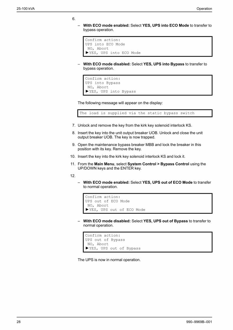
6.
– With ECO mode enabled: Select YES, UPS into ECO Mode to transfer tobypass operation.
Confirm action:UPS into ECO ModeNO, Abort
►YES, UPS into ECO Mode
– With ECO mode disabled: Select YES, UPS into Bypass to transfer tobypass operation.
Confirm action:UPS into BypassNO, Abort
►YES, UPS into Bypass
The following message will appear on the display:
The load is supplied via the static bypass switch
7. Unlock and remove the key from the kirk key solenoid interlock KS.
8. Insert the key into the unit output breaker UOB. Unlock and close the unitoutput breaker UOB. The key is now trapped.
9. Open the maintenance bypass breaker MBB and lock the breaker in thisposition with its key. Remove the key.
10. Insert the key into the kirk key solenoid interlock KS and lock it.
11. From theMain Menu, select System Control > Bypass Control using theUP/DOWN keys and the ENTER key.
12.
– With ECO mode enabled: Select YES, UPS out of ECO Mode to transferto normal operation.
Confirm action:UPS out of ECO ModeNO, Abort
►YES, UPS out of ECO Mode
– With ECO mode disabled: Select YES, UPS out of Bypass to transfer tonormal operation.
Confirm action:UPS out of BypassNO, Abort
►YES, UPS out of Bypass
The UPS is now in normal operation.
28 990–9969B–001
Operation 25-100 kVA
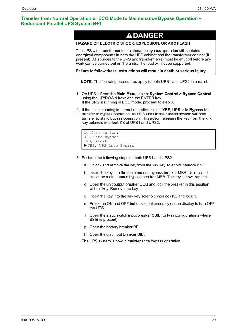
Transfer from Normal Operation or ECO Mode to Maintenance Bypass Operation –Redundant Parallel UPS System N+1
DANGERHAZARD OF ELECTRIC SHOCK, EXPLOSION, OR ARC FLASH
The UPS with transformer in maintenance bypass operation still containsenergized components in both the UPS cabinet and the transformer cabinet (ifpresent). All sources to the UPS and transformer(s) must be shut off before anywork can be carried out on the units. The load will not be supported.
Failure to follow these instructions will result in death or serious injury.
NOTE: The following procedures apply to both UPS1 and UPS2 in parallel.
1. On UPS1: From theMain Menu, select System Control > Bypass Controlusing the UP/DOWN keys and the ENTER key.If the UPS is running in ECO mode, proceed to step 3.
2. If the unit is running in normal operation, select YES, UPS into Bypass totransfer to bypass operation. All UPS units in the parallel system will nowtransfer to static bypass operation. This action releases the key from the kirkkey solenoid interlock KS of UPS1 and UPS2.
Confirm action:UPS into BypassNO, Abort
►YES, UPS into Bypass
3. Perform the following steps on both UPS1 and UPS2:
a. Unlock and remove the key from the kirk key solenoid interlock KS.
b. Insert the key into the maintenance bypass breaker MBB. Unlock andclose the maintenance bypass breaker MBB. The key is now trapped.
c. Open the unit output breaker UOB and lock the breaker in this positionwith its key. Remove the key.
d. Insert the key into the kirk key solenoid interlock KS and lock it.
e. Press the ON and OFF buttons simultaneously on the display to turn OFFthe UPS.
f. Open the static switch input breaker SSIB (only in configurations whereSSIB is present).
g. Open the battery breaker BB.
h. Open the unit input breaker UIB.
The UPS system is now in maintenance bypass operation.
990–9969B–001 29
25-100 kVA Operation
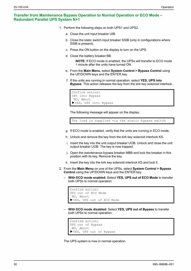
Transfer from Maintenance Bypass Operation to Normal Operation or ECO Mode –Redundant Parallel UPS System N+1
1. Perform the following steps on both UPS1 and UPS2.
a. Close the unit input breaker UIB.
b. Close the static switch input breaker SSIB (only in configurations whereSSIB is present).
c. Press the ON button on the display to turn on the UPS.
d. Close the battery breaker BB.NOTE: If ECO mode is enabled, the UPSs will transfer to ECO mode1 minute after the units have turned ON.
e. From theMain Menu, select System Control > Bypass Control usingthe UP/DOWN keys and the ENTER key.
f. If the units are running in normal operation, select YES, UPS intoBypass. This action releases the key from the kirk key solenoid interlock.
Confirm action:UPS into BypassNO, Abort
►YES, UPS into Bypass
The following message will appear on the display:
The load is supplied via the static bypass switch
g. If ECO mode is enabled, verify that the units are running in ECO mode.
h. Unlock and remove the key from the kirk key solenoid interlock KS.
i. Insert the key into the unit output breaker UOB. Unlock and close the unitoutput breaker UOB. The key is now trapped.
j. Open the maintenance bypass breaker MBB and lock the breaker in thisposition with its key. Remove the key.
k. Insert the key into the kirk key solenoid interlock KS and lock it.
2. From theMain Menu on one of the UPSs, select System Control > BypassControl using the UP/DOWN keys and the ENTER key.
– With ECO mode enabled: Select YES, UPS out of ECO Mode to transferboth UPSs to normal operation.
Confirm action:UPS out of ECO ModeNO, Abort
►YES, UPS out of ECO Mode
– With ECO mode disabled: Select YES, UPS out of Bypass to transferboth UPSs to normal operation.
Confirm action:UPS out of BypassNO, Abort
►YES, UPS out of Bypass
The UPS system is now in normal operation.
30 990–9969B–001
Operation 25-100 kVA
View the Event Log
1. From theMain Menu, select Event Logging > View Log using the UP/DOWN keys and the ENTER key. Wait a few seconds while the event log isbeing prepared.
2. Use the UP/DOWN keys to browse through the log entries. All system eventsand alarms are stored in this event log.
Clear the Event Log
1. From theMain Menu, select Event Logging > Clear Log > YES, Clear Logusing the UP/DOWN keys and the ENTER key.
View the Alarms
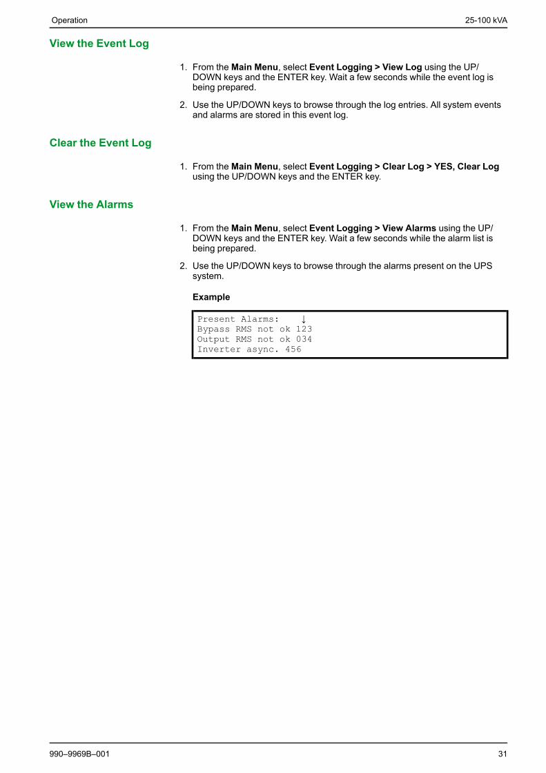
1. From theMain Menu, select Event Logging > View Alarms using the UP/DOWN keys and the ENTER key. Wait a few seconds while the alarm list isbeing prepared.
2. Use the UP/DOWN keys to browse through the alarms present on the UPSsystem.
Example
Present Alarms: ↓Bypass RMS not ok 123Output RMS not ok 034Inverter async. 456
990–9969B–001 31
25-100 kVA Operation
View Diagnosis
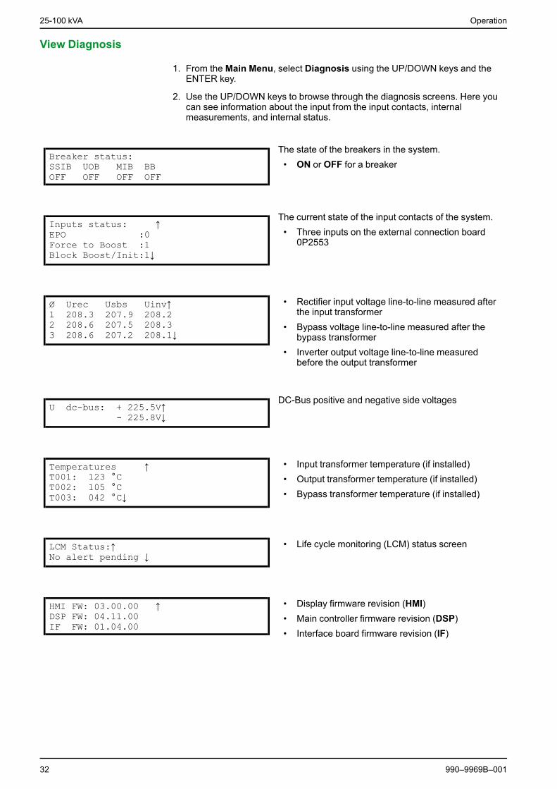
1. From theMain Menu, select Diagnosis using the UP/DOWN keys and theENTER key.
2. Use the UP/DOWN keys to browse through the diagnosis screens. Here youcan see information about the input from the input contacts, internalmeasurements, and internal status.
Breaker status:SSIB UOB MIB BBOFF OFF OFF OFF
The state of the breakers in the system.• ON or OFF for a breaker
Inputs status: ↑EPO :0Force to Boost :1Block Boost/Init:1↓
The current state of the input contacts of the system.• Three inputs on the external connection board
0P2553
Ø Urec Usbs Uinv↑1 208.3 207.9 208.22 208.6 207.5 208.33 208.6 207.2 208.1↓
• Rectifier input voltage line-to-line measured afterthe input transformer
• Bypass voltage line-to-line measured after thebypass transformer
• Inverter output voltage line-to-line measuredbefore the output transformer
U dc-bus: + 225.5V↑- 225.8V↓
DC-Bus positive and negative side voltages
Temperatures ↑T001: 123 °CT002: 105 °CT003: 042 °C↓
• Input transformer temperature (if installed)• Output transformer temperature (if installed)• Bypass transformer temperature (if installed)
LCM Status:↑No alert pending ↓
• Life cycle monitoring (LCM) status screen
HMI FW: 03.00.00 ↑DSP FW: 04.11.00IF FW: 01.04.00
• Display firmware revision (HMI)• Main controller firmware revision (DSP)• Interface board firmware revision (IF)
32 990–9969B–001
Operation 25-100 kVA
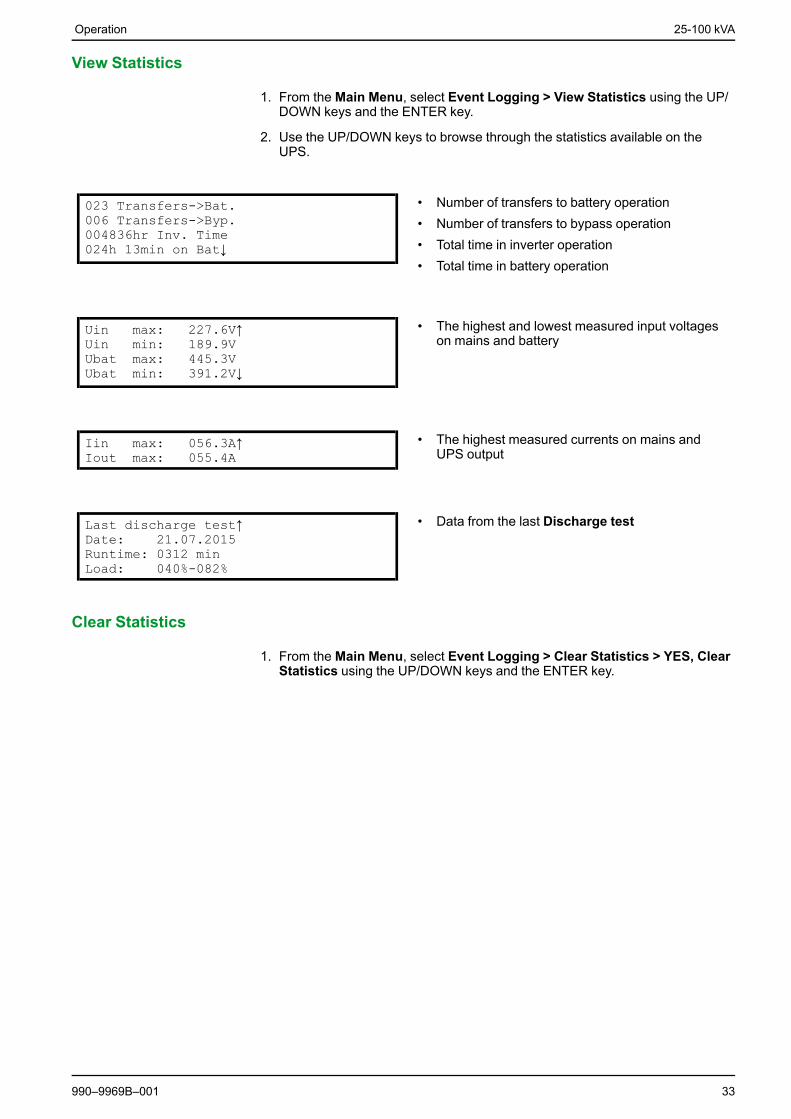
View Statistics
1. From theMain Menu, select Event Logging > View Statistics using the UP/DOWN keys and the ENTER key.
2. Use the UP/DOWN keys to browse through the statistics available on theUPS.
023 Transfers->Bat.006 Transfers->Byp.004836hr Inv. Time024h 13min on Bat↓
• Number of transfers to battery operation• Number of transfers to bypass operation• Total time in inverter operation• Total time in battery operation
Uin max: 227.6V↑Uin min: 189.9VUbat max: 445.3VUbat min: 391.2V↓
• The highest and lowest measured input voltageson mains and battery
Iin max: 056.3A↑Iout max: 055.4A
• The highest measured currents on mains andUPS output
Last discharge test↑Date: 21.07.2015Runtime: 0312 minLoad: 040%-082%
• Data from the last Discharge test
Clear Statistics
1. From theMain Menu, select Event Logging > Clear Statistics > YES, ClearStatistics using the UP/DOWN keys and the ENTER key.
990–9969B–001 33
25-100 kVA Configuration
Configuration
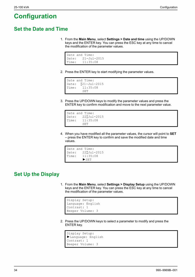
Set the Date and Time
1. From theMain Menu, select Settings > Date and time using the UP/DOWNkeys and the ENTER key. You can press the ESC key at any time to cancelthe modification of the parameter values.
Date and Time:Date: 21-Jul-2015Time: 11:35:08
2. Press the ENTER key to start modifying the parameter values.
Date and Time:Date: ↕21-Jul-2015Time: 11:35:08
SET
3. Press the UP/DOWN keys to modify the parameter values and press theENTER key to confirm modification and move to the next parameter value.
Date and Time:Date: 22↕Jul-2015Time: 11:35:08
SET
4. When you have modified all the parameter values, the cursor will point to SET– press the ENTER key to confirm and save the modified date and timevalues.
Date and Time:Date: 22↕Jul-2015Time: 11:35:08
►SET
Set Up the Display
1. From theMain Menu, select Settings > Display Setup using the UP/DOWNkeys and the ENTER key. You can press the ESC key at any time to cancelthe modification of the parameter values.
Display Setup:Language: EnglishContrast: 1Beeper Volume: 3
2. Press the UP/DOWN keys to select a parameter to modify and press theENTER key.
Display Setup:►Language: EnglishContrast: 1Beeper Volume: 3
34 990–9969B–001
Configuration 25-100 kVA
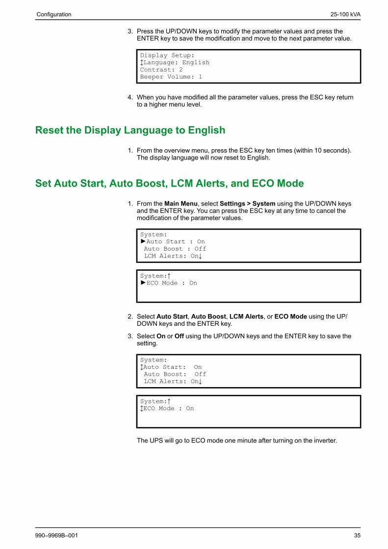
3. Press the UP/DOWN keys to modify the parameter values and press theENTER key to save the modification and move to the next parameter value.
Display Setup:↕Language: EnglishContrast: 2Beeper Volume: 1
4. When you have modified all the parameter values, press the ESC key returnto a higher menu level.
Reset the Display Language to English
1. From the overview menu, press the ESC key ten times (within 10 seconds).The display language will now reset to English.
Set Auto Start, Auto Boost, LCM Alerts, and ECO Mode
1. From theMain Menu, select Settings > System using the UP/DOWN keysand the ENTER key. You can press the ESC key at any time to cancel themodification of the parameter values.
System:►Auto Start : OnAuto Boost : OffLCM Alerts: On↓
System:↑►ECO Mode : On
2. Select Auto Start, Auto Boost, LCM Alerts, or ECO Mode using the UP/DOWN keys and the ENTER key.
3. Select On or Off using the UP/DOWN keys and the ENTER key to save thesetting.
System:↕Auto Start: OnAuto Boost: OffLCM Alerts: On↓
System:↑↕ECO Mode : On
The UPS will go to ECO mode one minute after turning on the inverter.
990–9969B–001 35
25-100 kVA Configuration
Set Battery Charge Mode
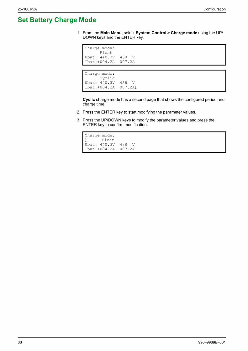
1. From theMain Menu, select System Control > Charge mode using the UP/DOWN keys and the ENTER key.
Charge mode:Float
Ubat: 440.3V 438 VIbat:+004.2A 007.2A
Charge mode:Cyclic
Ubat: 440.3V 438 VIbat:+004.2A 007.2A↓
Cyclic charge mode has a second page that shows the configured period andcharge time.
2. Press the ENTER key to start modifying the parameter values.
3. Press the UP/DOWN keys to modify the parameter values and press theENTER key to confirm modification.
Charge mode:↕ FloatUbat: 440.3V 438 VIbat:+004.2A 007.2A
36 990–9969B–001
Maintenance 25-100 kVA
Maintenance
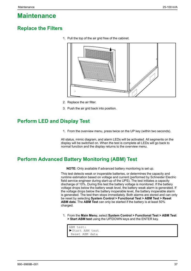
Replace the Filters
1. Pull the top of the air grid free of the cabinet.
2. Replace the air filter.
3. Push the air grid back into position.
Perform LED and Display Test
1. From the overview menu, press twice on the UP key (within two seconds).
All status, mimic diagram, and alarm LEDs will be activated. All segments on thedisplay will be switched on. When the test is complete all LEDs will go back tonormal function and the display returns to the overview menu.
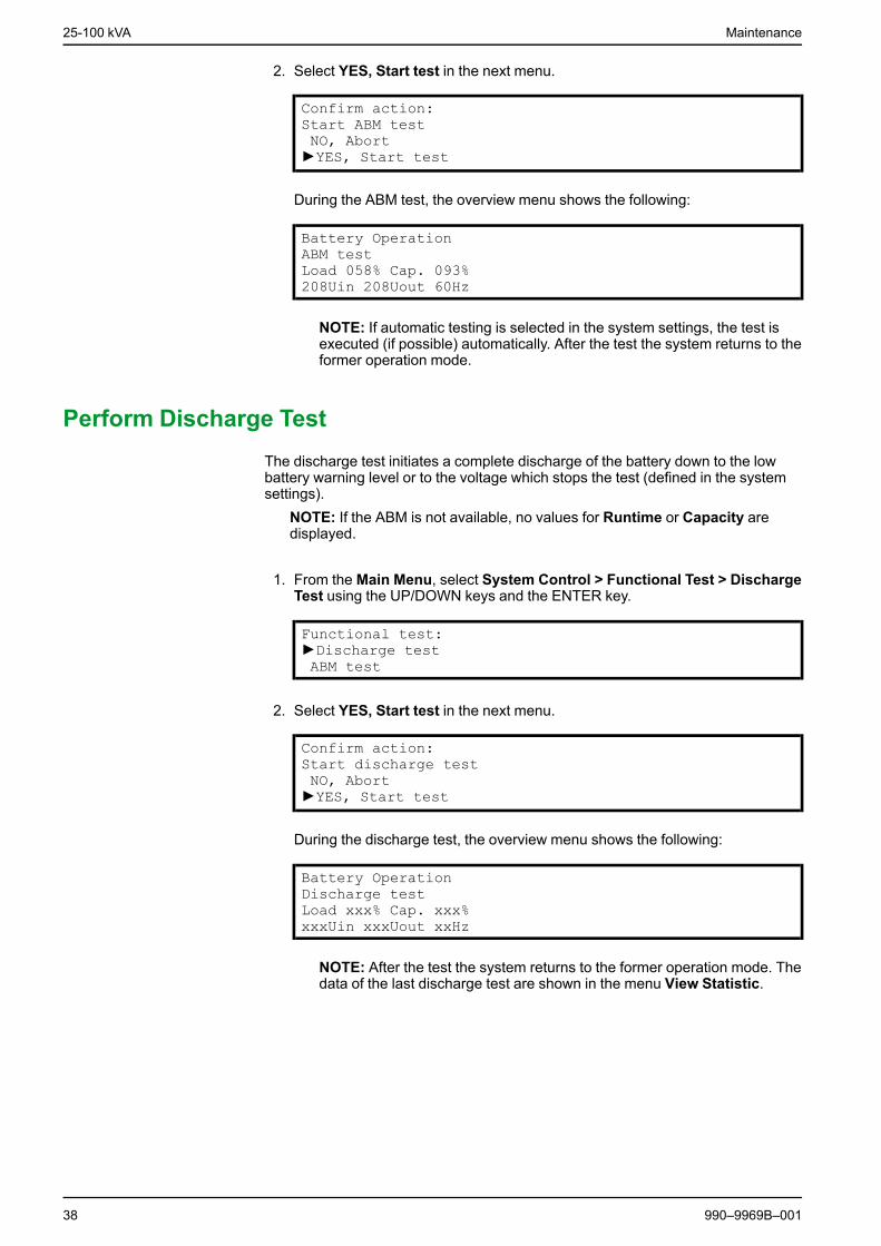
Perform Advanced Battery Monitoring (ABM) TestNOTE: Only available if advanced battery monitoring is set up.
This test detects weak or inoperable batteries, or determines the capacity andruntime estimation based on voltage and current (performed by Schneider Electricfield service engineer during start-up of the UPS). The test initiates a capacitydischarge of 10%. During this test the battery voltage is monitored. If the batteryvoltage drops below the battery weak level, the battery weak alarm is generated. Ifthe voltage drops below the battery inoperable level, the battery inoperable alarmis generated. The test then stops immediately. Both alarms are stored and can onlybe reset by selecting System Control > Functional Test > ABM Test > ResetABM data. The ABM Test can only be started if the battery is at least 50%charged.
1. From theMain Menu, select System Control > Functional Test > ABM Test> Start ABM test using the UP/DOWN keys and the ENTER key.
ABM test:►Start ABM testReset ABM data
990–9969B–001 37
25-100 kVA Maintenance
2. Select YES, Start test in the next menu.
Confirm action:Start ABM testNO, Abort
►YES, Start test
During the ABM test, the overview menu shows the following:
Battery OperationABM testLoad 058% Cap. 093%208Uin 208Uout 60Hz
NOTE: If automatic testing is selected in the system settings, the test isexecuted (if possible) automatically. After the test the system returns to theformer operation mode.
Perform Discharge TestThe discharge test initiates a complete discharge of the battery down to the lowbattery warning level or to the voltage which stops the test (defined in the systemsettings).
NOTE: If the ABM is not available, no values for Runtime or Capacity aredisplayed.
1. From theMain Menu, select System Control > Functional Test > DischargeTest using the UP/DOWN keys and the ENTER key.
Functional test:►Discharge testABM test
2. Select YES, Start test in the next menu.
Confirm action:Start discharge testNO, Abort
►YES, Start test
During the discharge test, the overview menu shows the following:
Battery OperationDischarge testLoad xxx% Cap. xxx%xxxUin xxxUout xxHz
NOTE: After the test the system returns to the former operation mode. Thedata of the last discharge test are shown in the menu View Statistic.
38 990–9969B–001
Maintenance 25-100 kVA
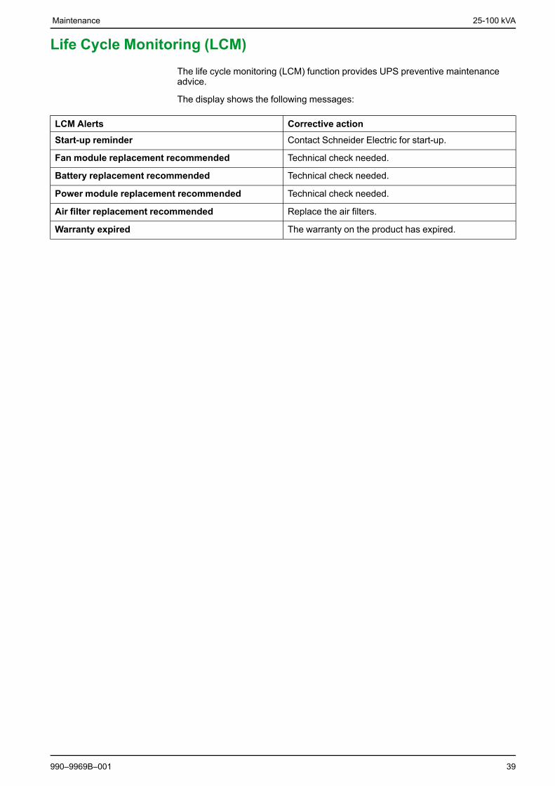
Life Cycle Monitoring (LCM)The life cycle monitoring (LCM) function provides UPS preventive maintenanceadvice.
The display shows the following messages:
LCM Alerts Corrective actionStart-up reminder Contact Schneider Electric for start-up.
Fan module replacement recommended Technical check needed.
Battery replacement recommended Technical check needed.
Power module replacement recommended Technical check needed.
Air filter replacement recommended Replace the air filters.
Warranty expired The warranty on the product has expired.
990–9969B–001 39
25-100 kVA Troubleshooting
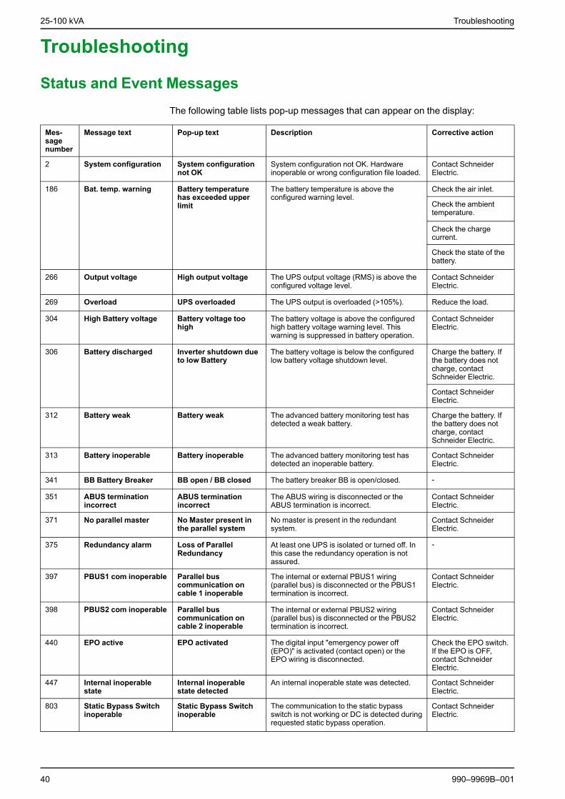
Troubleshooting
Status and Event MessagesThe following table lists pop-up messages that can appear on the display:
Mes-sagenumber
Message text Pop-up text Description Corrective action
2 System configuration System configurationnot OK
System configuration not OK. Hardwareinoperable or wrong configuration file loaded.
Contact SchneiderElectric.
186 Bat. temp. warning Battery temperaturehas exceeded upperlimit
The battery temperature is above theconfigured warning level.
Check the air inlet.
Check the ambienttemperature.
Check the chargecurrent.
Check the state of thebattery.
266 Output voltage High output voltage The UPS output voltage (RMS) is above theconfigured voltage level.
Contact SchneiderElectric.
269 Overload UPS overloaded The UPS output is overloaded (>105%). Reduce the load.
304 High Battery voltage Battery voltage toohigh
The battery voltage is above the configuredhigh battery voltage warning level. Thiswarning is suppressed in battery operation.
Contact SchneiderElectric.
306 Battery discharged Inverter shutdown dueto low Battery
The battery voltage is below the configuredlow battery voltage shutdown level.
Charge the battery. Ifthe battery does notcharge, contactSchneider Electric.
Contact SchneiderElectric.
312 Battery weak Battery weak The advanced battery monitoring test hasdetected a weak battery.
Charge the battery. Ifthe battery does notcharge, contactSchneider Electric.
313 Battery inoperable Battery inoperable The advanced battery monitoring test hasdetected an inoperable battery.
Contact SchneiderElectric.
341 BB Battery Breaker BB open / BB closed The battery breaker BB is open/closed. -
351 ABUS terminationincorrect
ABUS terminationincorrect
The ABUS wiring is disconnected or theABUS termination is incorrect.
Contact SchneiderElectric.
371 No parallel master No Master present inthe parallel system
No master is present in the redundantsystem.
Contact SchneiderElectric.
375 Redundancy alarm Loss of ParallelRedundancy
At least one UPS is isolated or turned off. Inthis case the redundancy operation is notassured.
-
397 PBUS1 com inoperable Parallel buscommunication oncable 1 inoperable
The internal or external PBUS1 wiring(parallel bus) is disconnected or the PBUS1termination is incorrect.
Contact SchneiderElectric.
398 PBUS2 com inoperable Parallel buscommunication oncable 2 inoperable
The internal or external PBUS2 wiring(parallel bus) is disconnected or the PBUS2termination is incorrect.
Contact SchneiderElectric.
440 EPO active EPO activated The digital input "emergency power off(EPO)" is activated (contact open) or theEPO wiring is disconnected.
Check the EPO switch.If the EPO is OFF,contact SchneiderElectric.
447 Internal inoperablestate
Internal inoperablestate detected
An internal inoperable state was detected. Contact SchneiderElectric.
803 Static Bypass Switchinoperable
Static Bypass Switchinoperable
The communication to the static bypassswitch is not working or DC is detected duringrequested static bypass operation.
Contact SchneiderElectric.
40 990–9969B–001
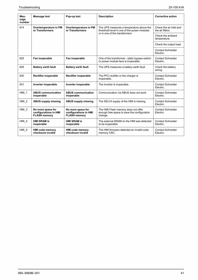
Troubleshooting 25-100 kVA
Mes-sagenumber
Message text Pop-up text Description Corrective action
814 Overtemperature in PMor Transformers
Overtemperature in PMor Transformers
The UPS measures a temperature above thethreshold level in one of the power modulesor in one of the transformers.
Check the air inlet andthe air filters.
Check the ambienttemperature.
Check the output load.
Contact SchneiderElectric.
825 Fan inoperable Fan inoperable One of the transformer-, static bypass switch-or power module fans is inoperable.
Contact SchneiderElectric.
826 Battery earth fault Battery earth fault The UPS measures a battery earth fault. Check the batterywiring.
830 Rectifier inoperable Rectifier inoperable The PFC rectifier or the charger isinoperable.
Contact SchneiderElectric.
831 Inverter inoperable Inverter inoperable The inverter is inoperable. Contact SchneiderElectric.
HMI_1 ABUS communicationinoperable
ABUS communicationinoperable
Communication via ABUS does not work. Contact SchneiderElectric.
HMI_2 ABUS supply missing ABUS supply missing The SELV4 supply of the HMI is missing. Contact SchneiderElectric.
HMI_3 No more space forconfigurations in HMIFLASH memory
No more space forconfigurations in HMIFLASH memory
The HMI Flash memory does not offerenough free space to save the configurationchange.
Contact SchneiderElectric.
HMI_4 HMI SRAM isinoperable
HMI SRAM isinoperable
The external SRAM on the HMI was detectedto be inoperable.
Contact SchneiderElectric.
HMI_5 HMI code memorychecksum invalid
HMI code memorychecksum invalid
The HMI firmware detected an invalid codememory CRC.
Contact SchneiderElectric.
990–9969B–001 41
25-100 kVA Troubleshooting
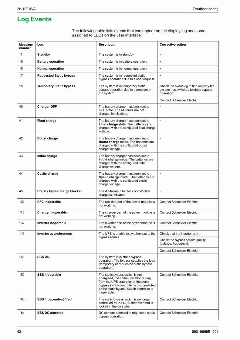
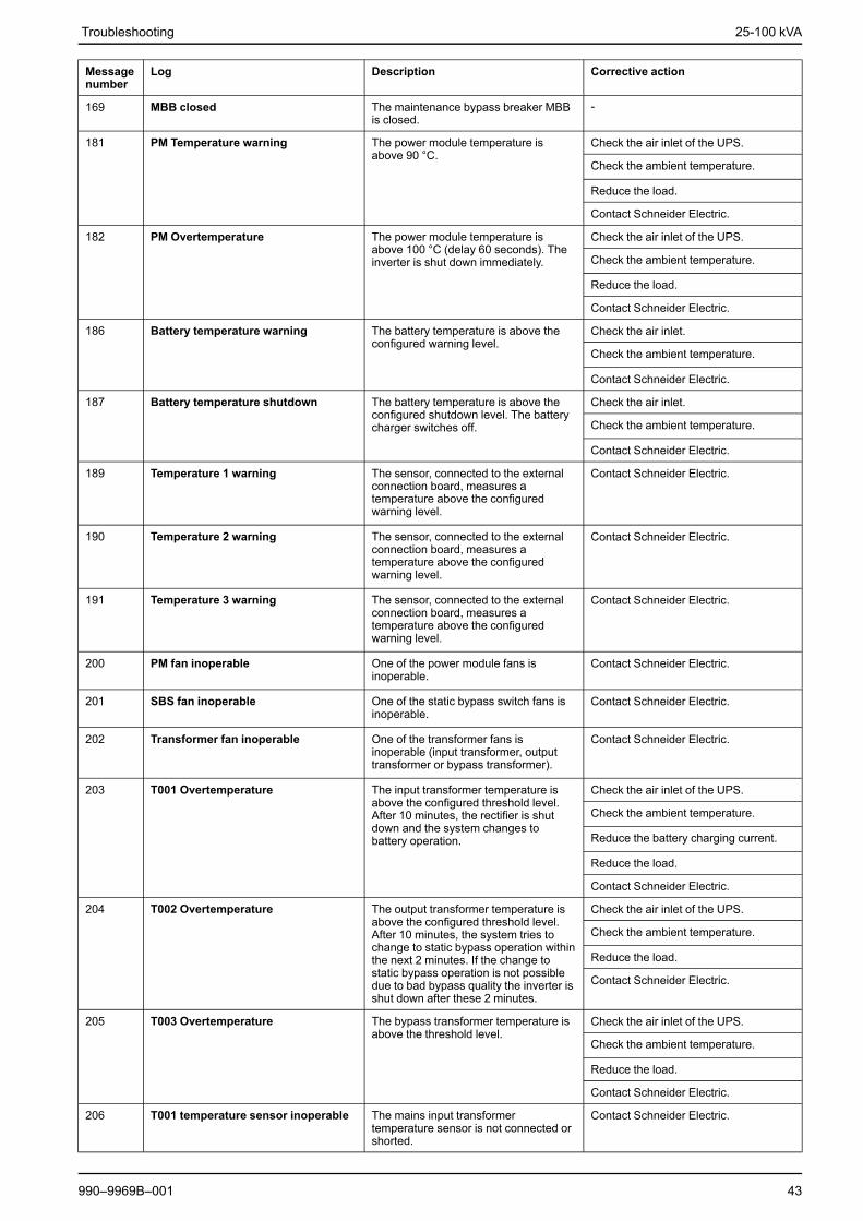
Log EventsThe following table lists events that can appear on the display log and someassigned to LEDs on the user interface:
Messagenumber
Log Description Corrective action
11 Standby The system is in standby. -
15 Battery operation The system is in battery operation. -
16 Normal operation The system is in normal operation. -
17 Requested Static bypass The system is in requested staticbypass operation due to a user request.
-
18 Temporary Static bypass The system is in temporary staticbypass operation due to a problem inthe system.
Check the event log to find out why thesystem has switched to static bypassoperation.
Contact Schneider Electric.
40 Charger OFF The battery charger has been set toOFF state. The batteries are notcharged in this state.
-
41 Float charge The battery charger has been set toFloat charge state. The batteries arecharged with the configured float chargevoltage.
-
42 Boost charge The battery charger has been set toBoost chargemode. The batteries arecharged with the configured boostcharge voltage.
-
43 Initial charge The battery charger has been set toInitial chargemode. The batteries arecharged with the configured initialcharge voltage.
-
44 Cyclic charge The battery charger has been set toCyclic chargemode. The batteries arecharged with the configured cycliccharge voltage.
-
45 Boost / Initial-Charge blocked The digital input to block boost/initialcharge is activated.
-
102 PFC inoperable The rectifier part of the power module isnot working.
Contact Schneider Electric.
110 Charger inoperable The charger part of the power module isnot working.
Contact Schneider Electric.
132 Inverter inoperable The inverter part of the power module isnot working.
Contact Schneider Electric.
146 Inverter asynchronous The UPS is unable to synchronize to thebypass source.
Check that the inverter is on.
Check the bypass source quality(voltage, frequency).
Contact Schneider Electric.
161 SBS ON The system is in static bypassoperation. The bypass supplies the load(temporary or requested static bypassoperation).
-
162 SBS inoperable The static bypass switch is notenergized, the communication wiringfrom the UPS controller to the staticbypass switch controller is disconnectedor the static bypass switch controller isinoperable.
Contact Schneider Electric.
163 SBS Independent fired The static bypass switch is no longercontrolled by the UPS controller and islocked in the on state.
Contact Schneider Electric.
164 SBS DC detected DC content detected in requested staticbypass operation.
Contact Schneider Electric.
42 990–9969B–001
Troubleshooting 25-100 kVA
Messagenumber
Log Description Corrective action
169 MBB closed The maintenance bypass breaker MBBis closed.
-
181 PM Temperature warning The power module temperature isabove 90 °C.
Check the air inlet of the UPS.
Check the ambient temperature.
Reduce the load.
Contact Schneider Electric.
182 PM Overtemperature The power module temperature isabove 100 °C (delay 60 seconds). Theinverter is shut down immediately.
Check the air inlet of the UPS.
Check the ambient temperature.
Reduce the load.
Contact Schneider Electric.
186 Battery temperature warning The battery temperature is above theconfigured warning level.
Check the air inlet.
Check the ambient temperature.
Contact Schneider Electric.
187 Battery temperature shutdown The battery temperature is above theconfigured shutdown level. The batterycharger switches off.
Check the air inlet.
Check the ambient temperature.
Contact Schneider Electric.
189 Temperature 1 warning The sensor, connected to the externalconnection board, measures atemperature above the configuredwarning level.
Contact Schneider Electric.
190 Temperature 2 warning The sensor, connected to the externalconnection board, measures atemperature above the configuredwarning level.
Contact Schneider Electric.
191 Temperature 3 warning The sensor, connected to the externalconnection board, measures atemperature above the configuredwarning level.
Contact Schneider Electric.
200 PM fan inoperable One of the power module fans isinoperable.
Contact Schneider Electric.
201 SBS fan inoperable One of the static bypass switch fans isinoperable.
Contact Schneider Electric.
202 Transformer fan inoperable One of the transformer fans isinoperable (input transformer, outputtransformer or bypass transformer).
Contact Schneider Electric.
203 T001 Overtemperature The input transformer temperature isabove the configured threshold level.After 10 minutes, the rectifier is shutdown and the system changes tobattery operation.
Check the air inlet of the UPS.
Check the ambient temperature.
Reduce the battery charging current.
Reduce the load.
Contact Schneider Electric.
204 T002 Overtemperature The output transformer temperature isabove the configured threshold level.After 10 minutes, the system tries tochange to static bypass operation withinthe next 2 minutes. If the change tostatic bypass operation is not possibledue to bad bypass quality the inverter isshut down after these 2 minutes.
Check the air inlet of the UPS.
Check the ambient temperature.
Reduce the load.
Contact Schneider Electric.
205 T003 Overtemperature The bypass transformer temperature isabove the threshold level.
Check the air inlet of the UPS.
Check the ambient temperature.
Reduce the load.
Contact Schneider Electric.
206 T001 temperature sensor inoperable The mains input transformertemperature sensor is not connected orshorted.
Contact Schneider Electric.
990–9969B–001 43
25-100 kVA Troubleshooting
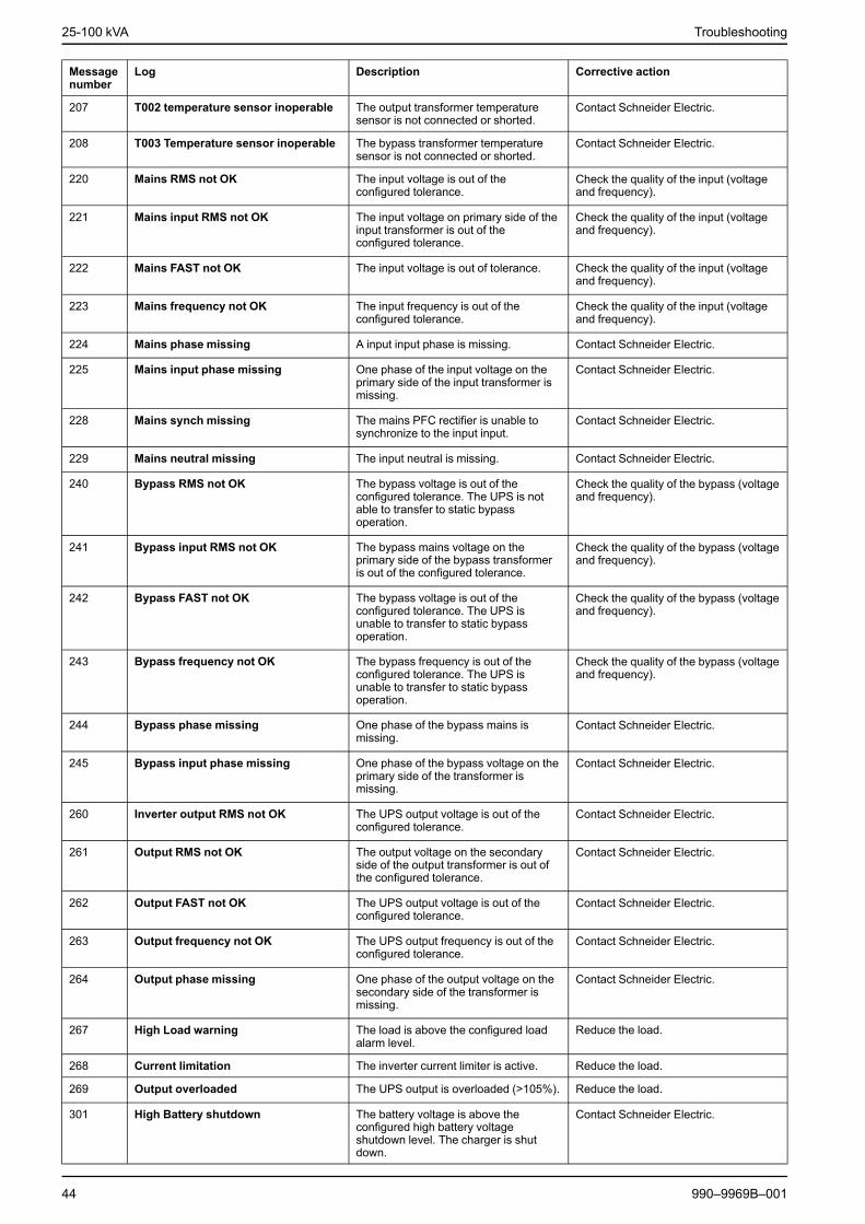
Messagenumber
Log Description Corrective action
207 T002 temperature sensor inoperable The output transformer temperaturesensor is not connected or shorted.
Contact Schneider Electric.
208 T003 Temperature sensor inoperable The bypass transformer temperaturesensor is not connected or shorted.
Contact Schneider Electric.
220 Mains RMS not OK The input voltage is out of theconfigured tolerance.
Check the quality of the input (voltageand frequency).
221 Mains input RMS not OK The input voltage on primary side of theinput transformer is out of theconfigured tolerance.
Check the quality of the input (voltageand frequency).
222 Mains FAST not OK The input voltage is out of tolerance. Check the quality of the input (voltageand frequency).
223 Mains frequency not OK The input frequency is out of theconfigured tolerance.
Check the quality of the input (voltageand frequency).
224 Mains phase missing A input input phase is missing. Contact Schneider Electric.
225 Mains input phase missing One phase of the input voltage on theprimary side of the input transformer ismissing.
Contact Schneider Electric.
228 Mains synch missing The mains PFC rectifier is unable tosynchronize to the input input.
Contact Schneider Electric.
229 Mains neutral missing The input neutral is missing. Contact Schneider Electric.
240 Bypass RMS not OK The bypass voltage is out of theconfigured tolerance. The UPS is notable to transfer to static bypassoperation.
Check the quality of the bypass (voltageand frequency).
241 Bypass input RMS not OK The bypass mains voltage on theprimary side of the bypass transformeris out of the configured tolerance.
Check the quality of the bypass (voltageand frequency).
242 Bypass FAST not OK The bypass voltage is out of theconfigured tolerance. The UPS isunable to transfer to static bypassoperation.
Check the quality of the bypass (voltageand frequency).
243 Bypass frequency not OK The bypass frequency is out of theconfigured tolerance. The UPS isunable to transfer to static bypassoperation.
Check the quality of the bypass (voltageand frequency).
244 Bypass phase missing One phase of the bypass mains ismissing.
Contact Schneider Electric.
245 Bypass input phase missing One phase of the bypass voltage on theprimary side of the transformer ismissing.
Contact Schneider Electric.
260 Inverter output RMS not OK The UPS output voltage is out of theconfigured tolerance.
Contact Schneider Electric.
261 Output RMS not OK The output voltage on the secondaryside of the output transformer is out ofthe configured tolerance.
Contact Schneider Electric.
262 Output FAST not OK The UPS output voltage is out of theconfigured tolerance.
Contact Schneider Electric.
263 Output frequency not OK The UPS output frequency is out of theconfigured tolerance.
Contact Schneider Electric.
264 Output phase missing One phase of the output voltage on thesecondary side of the transformer ismissing.
Contact Schneider Electric.
267 High Load warning The load is above the configured loadalarm level.
Reduce the load.
268 Current limitation The inverter current limiter is active. Reduce the load.
269 Output overloaded The UPS output is overloaded (>105%). Reduce the load.
301 High Battery shutdown The battery voltage is above theconfigured high battery voltageshutdown level. The charger is shutdown.
Contact Schneider Electric.
44 990–9969B–001
Troubleshooting 25-100 kVA
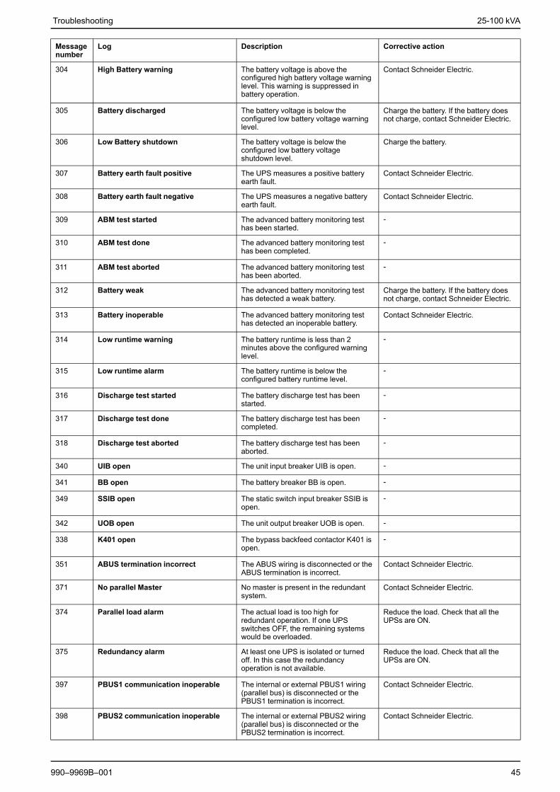
Messagenumber
Log Description Corrective action
304 High Battery warning The battery voltage is above theconfigured high battery voltage warninglevel. This warning is suppressed inbattery operation.
Contact Schneider Electric.
305 Battery discharged The battery voltage is below theconfigured low battery voltage warninglevel.
Charge the battery. If the battery doesnot charge, contact Schneider Electric.
306 Low Battery shutdown The battery voltage is below theconfigured low battery voltageshutdown level.
Charge the battery.
307 Battery earth fault positive The UPS measures a positive batteryearth fault.
Contact Schneider Electric.
308 Battery earth fault negative The UPS measures a negative batteryearth fault.
Contact Schneider Electric.
309 ABM test started The advanced battery monitoring testhas been started.
-
310 ABM test done The advanced battery monitoring testhas been completed.
-
311 ABM test aborted The advanced battery monitoring testhas been aborted.
-
312 Battery weak The advanced battery monitoring testhas detected a weak battery.
Charge the battery. If the battery doesnot charge, contact Schneider Electric.
313 Battery inoperable The advanced battery monitoring testhas detected an inoperable battery.
Contact Schneider Electric.
314 Low runtime warning The battery runtime is less than 2minutes above the configured warninglevel.
-
315 Low runtime alarm The battery runtime is below theconfigured battery runtime level.
-
316 Discharge test started The battery discharge test has beenstarted.
-
317 Discharge test done The battery discharge test has beencompleted.
-
318 Discharge test aborted The battery discharge test has beenaborted.
-
340 UIB open The unit input breaker UIB is open. -
341 BB open The battery breaker BB is open. -
349 SSIB open The static switch input breaker SSIB isopen.
-
342 UOB open The unit output breaker UOB is open. -
338 K401 open The bypass backfeed contactor K401 isopen.
-
351 ABUS termination incorrect The ABUS wiring is disconnected or theABUS termination is incorrect.
Contact Schneider Electric.
371 No parallel Master No master is present in the redundantsystem.
Contact Schneider Electric.
374 Parallel load alarm The actual load is too high forredundant operation. If one UPSswitches OFF, the remaining systemswould be overloaded.
Reduce the load. Check that all theUPSs are ON.
375 Redundancy alarm At least one UPS is isolated or turnedoff. In this case the redundancyoperation is not available.
Reduce the load. Check that all theUPSs are ON.
397 PBUS1 communication inoperable The internal or external PBUS1 wiring(parallel bus) is disconnected or thePBUS1 termination is incorrect.
Contact Schneider Electric.
398 PBUS2 communication inoperable The internal or external PBUS2 wiring(parallel bus) is disconnected or thePBUS2 termination is incorrect.
Contact Schneider Electric.
990–9969B–001 45
25-100 kVA Troubleshooting
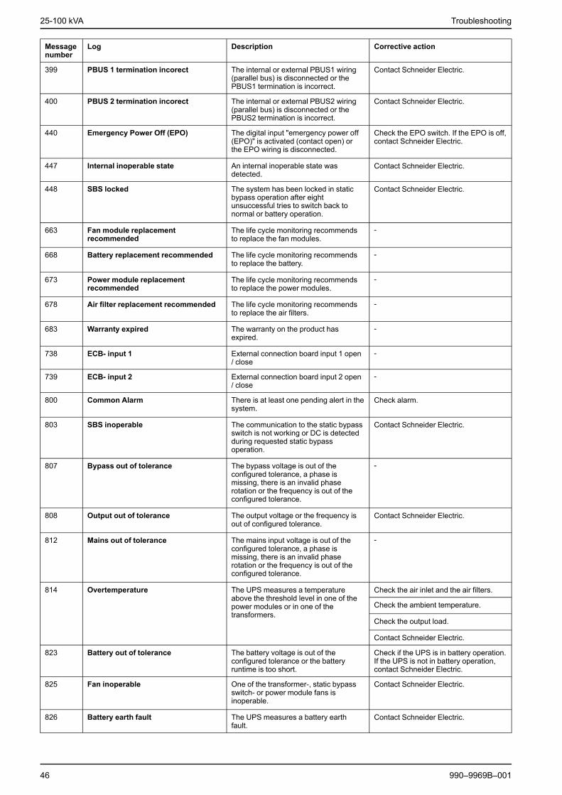
Messagenumber
Log Description Corrective action
399 PBUS 1 termination incorect The internal or external PBUS1 wiring(parallel bus) is disconnected or thePBUS1 termination is incorrect.
Contact Schneider Electric.
400 PBUS 2 termination incorect The internal or external PBUS2 wiring(parallel bus) is disconnected or thePBUS2 termination is incorrect.
Contact Schneider Electric.
440 Emergency Power Off (EPO) The digital input "emergency power off(EPO)" is activated (contact open) orthe EPO wiring is disconnected.
Check the EPO switch. If the EPO is off,contact Schneider Electric.
447 Internal inoperable state An internal inoperable state wasdetected.
Contact Schneider Electric.
448 SBS locked The system has been locked in staticbypass operation after eightunsuccessful tries to switch back tonormal or battery operation.
Contact Schneider Electric.
663 Fan module replacementrecommended
The life cycle monitoring recommendsto replace the fan modules.
-
668 Battery replacement recommended The life cycle monitoring recommendsto replace the battery.
-
673 Power module replacementrecommended
The life cycle monitoring recommendsto replace the power modules.
-
678 Air filter replacement recommended The life cycle monitoring recommendsto replace the air filters.
-
683 Warranty expired The warranty on the product hasexpired.
-
738 ECB- input 1 External connection board input 1 open/ close
-
739 ECB- input 2 External connection board input 2 open/ close
-
800 Common Alarm There is at least one pending alert in thesystem.
Check alarm.
803 SBS inoperable The communication to the static bypassswitch is not working or DC is detectedduring requested static bypassoperation.
Contact Schneider Electric.
807 Bypass out of tolerance The bypass voltage is out of theconfigured tolerance, a phase ismissing, there is an invalid phaserotation or the frequency is out of theconfigured tolerance.
-
808 Output out of tolerance The output voltage or the frequency isout of configured tolerance.
Contact Schneider Electric.
812 Mains out of tolerance The mains input voltage is out of theconfigured tolerance, a phase ismissing, there is an invalid phaserotation or the frequency is out of theconfigured tolerance.
-
814 Overtemperature The UPS measures a temperatureabove the threshold level in one of thepower modules or in one of thetransformers.
Check the air inlet and the air filters.
Check the ambient temperature.
Check the output load.
Contact Schneider Electric.
823 Battery out of tolerance The battery voltage is out of theconfigured tolerance or the batteryruntime is too short.
Check if the UPS is in battery operation.If the UPS is not in battery operation,contact Schneider Electric.
825 Fan inoperable One of the transformer-, static bypassswitch- or power module fans isinoperable.
Contact Schneider Electric.
826 Battery earth fault The UPS measures a battery earthfault.
Contact Schneider Electric.
46 990–9969B–001
Troubleshooting 25-100 kVA
Messagenumber
Log Description Corrective action
830 Rectifier inoperable The PFC rectifier or the charger isinoperable.
Contact Schneider Electric.
831 Inverter inoperable The inverter is inoperable. Contact Schneider Electric.
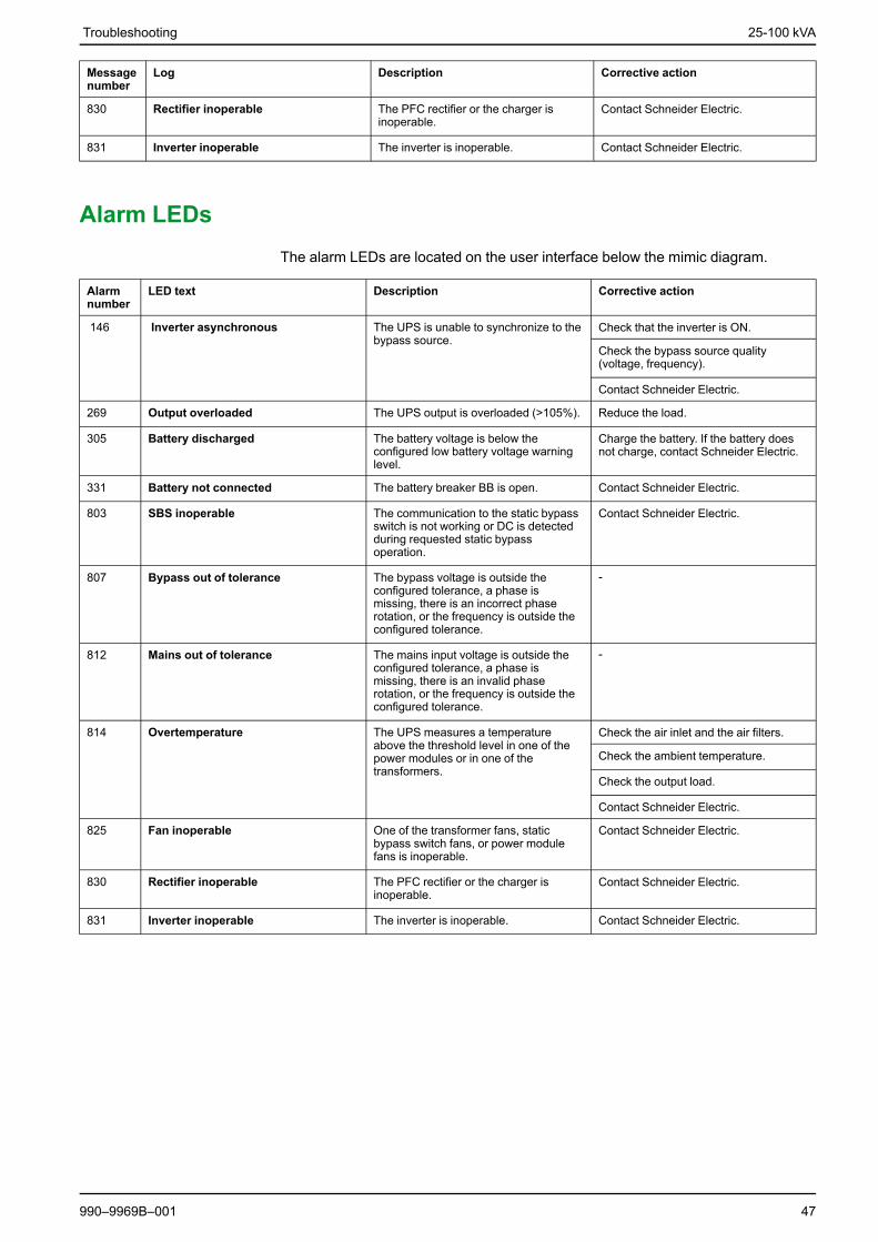
Alarm LEDsThe alarm LEDs are located on the user interface below the mimic diagram.
Alarmnumber
LED text Description Corrective action
146 Inverter asynchronous The UPS is unable to synchronize to thebypass source.
Check that the inverter is ON.
Check the bypass source quality(voltage, frequency).
Contact Schneider Electric.
269 Output overloaded The UPS output is overloaded (>105%). Reduce the load.
305 Battery discharged The battery voltage is below theconfigured low battery voltage warninglevel.
Charge the battery. If the battery doesnot charge, contact Schneider Electric.
331 Battery not connected The battery breaker BB is open. Contact Schneider Electric.
803 SBS inoperable The communication to the static bypassswitch is not working or DC is detectedduring requested static bypassoperation.
Contact Schneider Electric.
807 Bypass out of tolerance The bypass voltage is outside theconfigured tolerance, a phase ismissing, there is an incorrect phaserotation, or the frequency is outside theconfigured tolerance.
-
812 Mains out of tolerance The mains input voltage is outside theconfigured tolerance, a phase ismissing, there is an invalid phaserotation, or the frequency is outside theconfigured tolerance.
-
814 Overtemperature The UPS measures a temperatureabove the threshold level in one of thepower modules or in one of thetransformers.
Check the air inlet and the air filters.
Check the ambient temperature.
Check the output load.
Contact Schneider Electric.
825 Fan inoperable One of the transformer fans, staticbypass switch fans, or power modulefans is inoperable.
Contact Schneider Electric.
830 Rectifier inoperable The PFC rectifier or the charger isinoperable.
Contact Schneider Electric.
831 Inverter inoperable The inverter is inoperable. Contact Schneider Electric.
990–9969B–001 47
25-100 kVA Troubleshooting
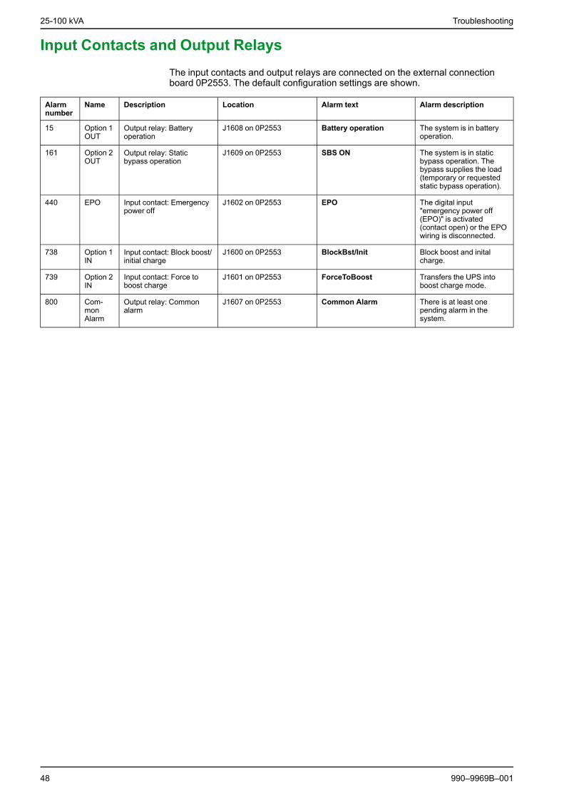
Input Contacts and Output RelaysThe input contacts and output relays are connected on the external connectionboard 0P2553. The default configuration settings are shown.
Alarmnumber
Name Description Location Alarm text Alarm description
15 Option 1OUT
Output relay: Batteryoperation
J1608 on 0P2553 Battery operation The system is in batteryoperation.
161 Option 2OUT
Output relay: Staticbypass operation
J1609 on 0P2553 SBS ON The system is in staticbypass operation. Thebypass supplies the load(temporary or requestedstatic bypass operation).
440 EPO Input contact: Emergencypower off
J1602 on 0P2553 EPO The digital input"emergency power off(EPO)" is activated(contact open) or the EPOwiring is disconnected.
738 Option 1IN
Input contact: Block boost/initial charge
J1600 on 0P2553 BlockBst/Init Block boost and initalcharge.
739 Option 2IN
Input contact: Force toboost charge
J1601 on 0P2553 ForceToBoost Transfers the UPS intoboost charge mode.
800 Com-monAlarm
Output relay: Commonalarm
J1607 on 0P2553 Common Alarm There is at least onepending alarm in thesystem.
48 990–9969B–001


Schneider Electric35 rue Joseph Monier92500 Rueil MalmaisonFrance
+ 33 (0) 1 41 29 70 00
www.schneider-electric.com
As standards, specifications, and design change from time to time,please ask for confirmation of the information given in this publication.
© 2016 – 2018 Schneider Electric. All rights reserved.
990–9969B–001