Goals
• To set up the mathematics and algorithms to perform ray tracing.
• To create highly realistic images, which include transparency and refraction of light.
• To develop tools for working with solid 3D texture and bitmapped images.
• To add surface texture to objects in the scene in order to enliven them.
• To study the creation of solid (3D) textures, such as wood grain and marble, in objects, and to see how to ray trace such objects.
• To create a much richer class of object shapes based on constructive solid geometry (CSG) and to learn how to raytrace scenes populated with such objects.
Ray Tracing
• We know how to render scenes composed of polygonal meshes, including shading models that represent—at least approximately—how light reflects from the surface of a polygon.
• Ray tracing thinks of the frame buffer as an array of pixels positioned in space with the eye looking through it into the scene.
• For each pixel in the frame buffer we ask: What does the eye see through this pixel?
Ray Tracing (2)
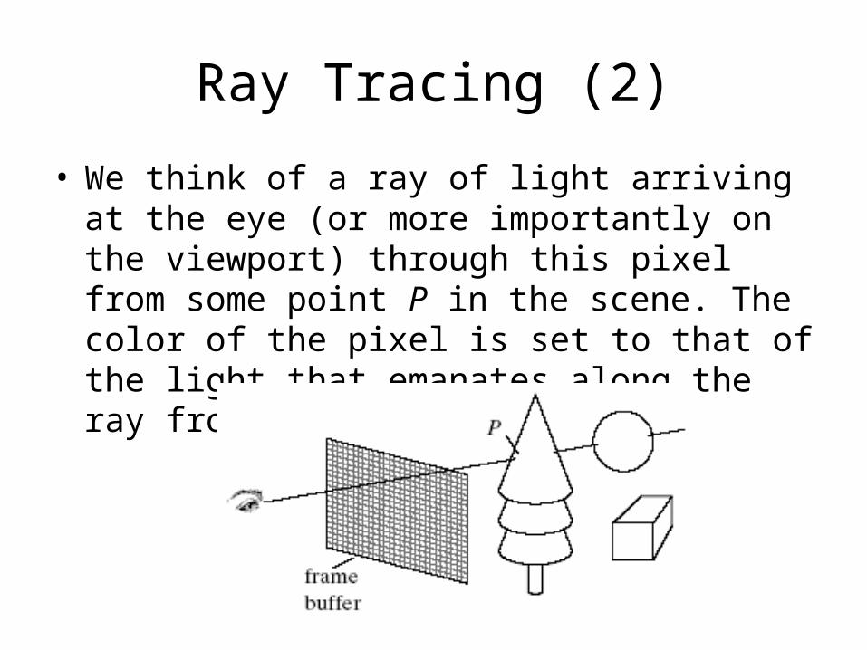
• We think of a ray of light arriving at the eye (or more importantly on the viewport) through this pixel from some point P in the scene. The color of the pixel is set to that of the light that emanates along the ray from point P in the scene.
Ray Tracing (3)
• In practice, ray tracing follows a ray from the eye through the pixel center and out into the scene.
• Its path is tested against each object in the scene to see which object (if any) it hits first and at what point.
• A parameter t is used to associate the ray’s position with our abstract notion of time so that we can say “the ray is here now” or “the ray reaches this point first.”
Ray Tracing (4)
• Ray tracing automatically solves the hidden surface removal problem, since the first surface hit by the ray is the closest object to the eye. More remote surfaces are ignored.
• Using a description of light sources in the scene, the same shading model as before is applied to the first hit point, and the ambient, diffuse, and specular components of light are computed.
• The resulting color is then displayed at the pixel.
Ray Tracing (5)
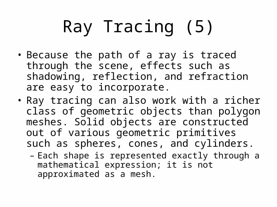
• Because the path of a ray is traced through the scene, effects such as shadowing, reflection, and refraction are easy to incorporate.
• Ray tracing can also work with a richer class of geometric objects than polygon meshes. Solid objects are constructed out of various geometric primitives such as spheres, cones, and cylinders. – Each shape is represented exactly through a
mathematical expression; it is not approximated as a mesh.
Ray Tracing (6)
• The shapes can be transformed to alter their size and orientation before they are added to the scene, providing more modeling power for complex scenes.
• The Scene Description Language (SDL) proves very useful in describing the objects in a scene.
Geometry of Ray Tracing
• In order to trace rays, we need a convenient representation for the ray (a parametric representation will be the most serviceable) that passes through a particular pixel.
• By way of warning, a large number of parameters will be necessary in order to describe exactly the geometry of the ray tracing process, which may seem overwhelming at first.
Geometry of Ray Tracing (2)
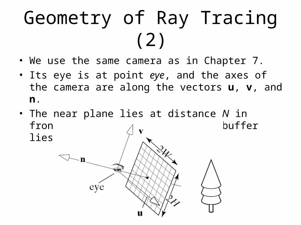
• We use the same camera as in Chapter 7.• Its eye is at point eye, and the axes of the camera are
along the vectors u, v, and n. • The near plane lies at distance N in front of the eye, and
the frame buffer lies in the near plane.
Geometry of Ray Tracing (3)
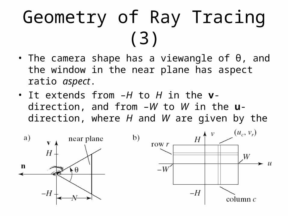
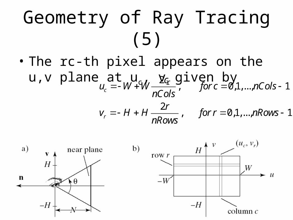
• The camera shape has a viewangle of θ, and the window in the near plane has aspect ratio aspect.
• It extends from –H to H in the v-direction, and from –W to W in the u-direction, where H and W are given by the expressions H = N tan(θ/2) and W = H*aspect.
Geometry of Ray Tracing (4)
• We think of the viewport being pasted onto the window in the near plane so that the eye is looking through individual pixels out into the scene.
• Suppose there are nCols by nRows of pixels in the viewport, and consider the pixel at row r and column c, where r varies from 0 to nRows – 1 and c varies from 0 to nCols –1. We’ll call this the “rc-th pixel”.
• We shall do all computations for the path of a ray in terms of the ray through the rc-th pixel. As always, we count rows from bottom to top and columns from left to right.
Geometry of Ray Tracing (5)
• The rc-th pixel appears on the u,v plane at uc, vr given by 2
, 0,1,..., 1
2, 0,1,..., 1
c
r
cu W W for c nCols
nColsr
v H H for r nRowsnRows
Geometry of Ray Tracing (6)
• To find an expression for a ray that passes through this point, we will need to express where it lies in 3D: the actual point on the near plane.
• Find how far this point is from the eye: Start at eye and determine how far you must go in each of the directions u, v, and n to reach the pixel corner. – Why do we use the corner rather than the center?
Pixels are so tiny that we cannot distinguish the corner from the center.
• You must go distance N in the negative n-direction, distance uc along u, and distance vr along v. Thus the 3D point is given by
eye N u vc r n u v
Geometry of Ray Tracing (7)
• We parametrize the position of a ray along its path using t, which is conveniently taken to be time. As t increases, the ray moves further and further along its path.
• By design, it starts at the eye at t = 0 and reaches the lower left corner of the rc-th pixel at t = 1.
• The basic operation of ray tracing is to compute where this ray lies at each instant t between 0 and 1, and specifically to find which if any) objects it hits. The ray of interest moves at constant speed in straight line segments and passes through a given pixel on the near plane.
• Speaking very roughly in pseudo code form, the parametric expression for the ray is:
( ) (1 )r t eye t pixelcorner t
Geometry of Ray Tracing (8)
• Substituting for pixelcorner, we get the detailed parametric form for the rc-th ray:
• The starting point and direction of this ray are
( ) (1 ) ( )c rr t eye t eye N u v t n u v
where( )
2 21 1
rc
rc
r t eye t
c rN W H
nCols nRows
dir
dir n u v
Geometry of Ray Tracing (9)
• Note that as t increases from 0, the ray point moves farther and farther from the eye.
• If the ray strikes two objects in its path, say at times ta and tb, the object lying closer to the eye will be the one hit at the lower value of t.
• Sorting the objects by depth from the eye corresponds to sorting the hit times at which the objects are intersected by the ray.
• If we accept as the hit object only the first object hit (that with the smallest hit time), the hidden surface removal problem is automatically solved!
• Also, any objects that are hit at a negative t must lie behind the eye and so are ignored.
Overview of Ray Tracing
• The scene to be ray traced is inhabited by various geometric objects and light sources, each having a specified shape, size, and position. – These objects are described in some fashion and
stored in an object list. • The camera is created. • Then for each pixel in turn we construct a ray
that starts at the eye and passes through the lower left corner of the pixel. This involves simply evaluating the direction dirrc for the rc-th ray.
Pseudocode for Ray Tracing
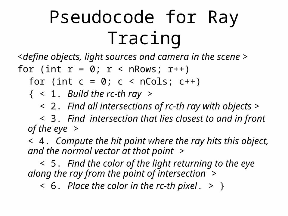
<define objects, light sources and camera in the scene >for (int r = 0; r < nRows; r++) for (int c = 0; c < nCols; c++) { < 1. Build the rc-th ray > < 2. Find all intersections of rc-th ray with objects > < 3. Find intersection that lies closest to and in front of
the eye >< 4. Compute the hit point where the ray hits this object, and the normal vector at that point >
< 5. Find the color of the light returning to the eye along the ray from the point of intersection >
< 6. Place the color in the rc-th pixel. > }
Overview of Ray Tracing (2)
• Steps 3-5 are new :• We first find whether the rc-th ray intersects each object
in the list, and if so, we note the “hit time”- the value of t at which the ray r(t) coincides with the object’s surface.
• When all objects have been tested, the object with the smallest hit time is the closest to the eye.
• The location of the hit point on the object is then found, along with the normal vector to this object’s surface at the hit point.
• The color of the light that reflects off this object, in the direction of the eye, is then computed and stored in the pixel.
Overview of Ray Tracing (3)
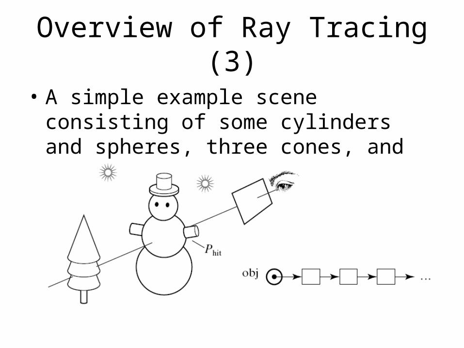
• A simple example scene consisting of some cylinders and spheres, three cones, and two light sources.
Overview of Ray Tracing (4)
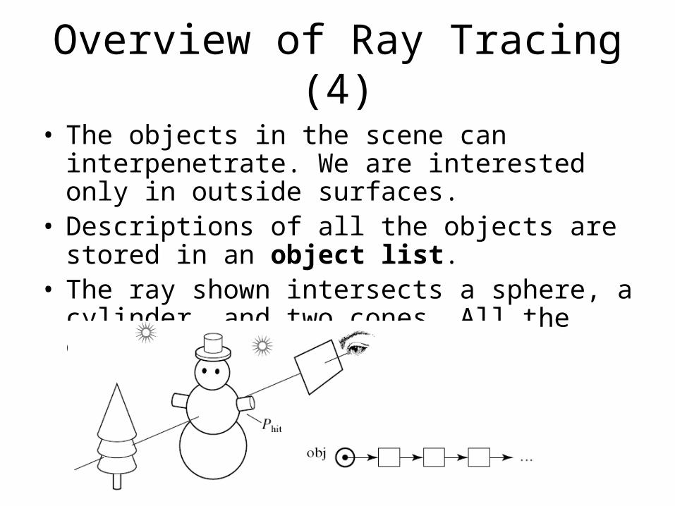
• The objects in the scene can interpenetrate. We are interested only in outside surfaces.
• Descriptions of all the objects are stored in an object list.
• The ray shown intersects a sphere, a cylinder, and two cones. All the other objects are missed.
Overview of Ray Tracing (5)
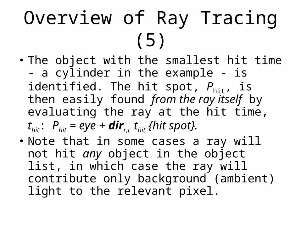
• The object with the smallest hit time - a cylinder in the example - is identified. The hit spot, Phit, is then easily found from the ray itself by evaluating the ray at the hit time, thit: Phit = eye + dirr,c thit {hit spot}.
• Note that in some cases a ray will not hit any object in the object list, in which case the ray will contribute only background (ambient) light to the relevant pixel.
Intersection of a Ray with an Object
• The Scene class can read a file in the SDL language and build a list of the objects in the scene. We will use this tool for ray tracing, building the scene with:
Scene scn; // create a scenescn.read(“myScene.dat”); // read the SDL scene file
• The objects in the scene are created and placed on a list. Each object is an instance of a generic shape such as a sphere or cone, along with an affine transformation that specifies how it is scaled, oriented, and positioned in the scene.
Intersection of a Ray with an Object (2)
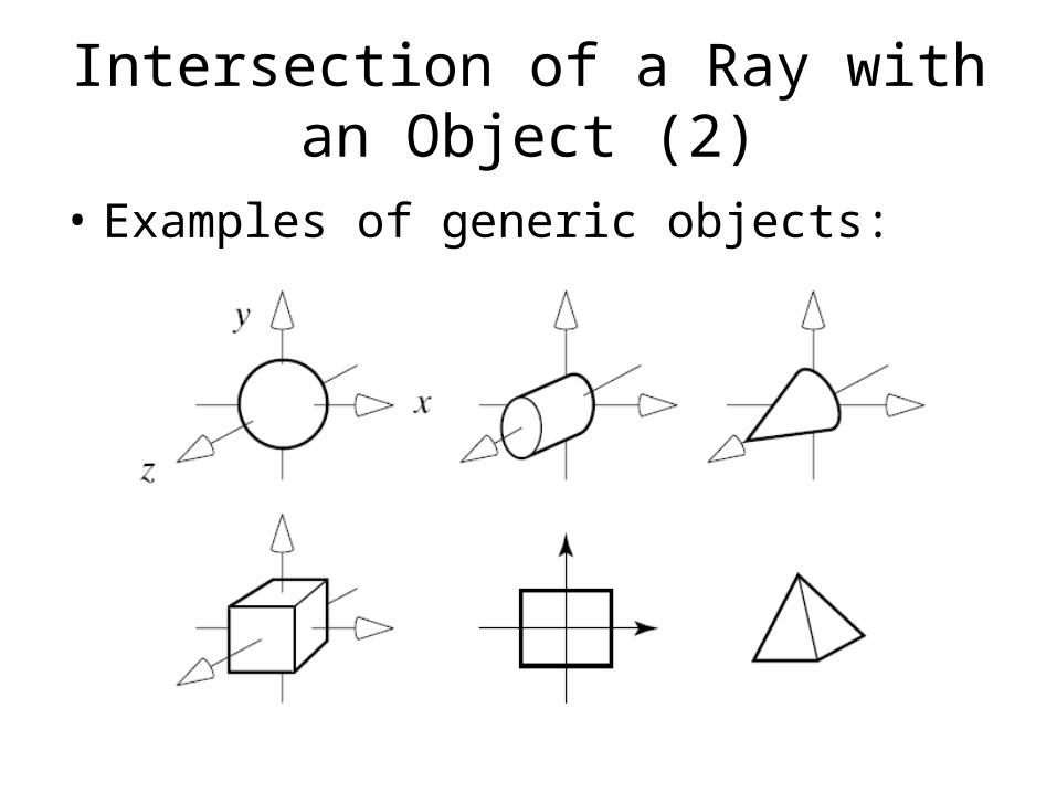
• Examples of generic objects:
Intersection of a Ray with an Object (3)
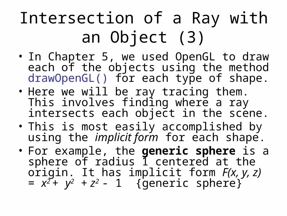
• In Chapter 5, we used OpenGL to draw each of the objects using the method drawOpenGL() for each type of shape.
• Here we will be ray tracing them. This involves finding where a ray intersects each object in the scene.
• This is most easily accomplished by using the implicit form for each shape.
• For example, the generic sphere is a sphere of radius 1 centered at the origin. It has implicit form F(x, y, z) = x2 + y2 + z2 - 1 {generic sphere}
Intersection of a Ray with an Object (4)
• If we use for convenience the notation F(P) where the argument of the implicit function is a point, the implicit form for the generic sphere becomes F(P) = |P|2 – 1.
• The generic cylinder has radius 1, is aligned along the z-axis with an axis of length 1, and has the implicit form F(x, y, z) = x2 + y2 - 1 = 0 for 0 < z < 1.
Intersection of a Ray with an Object (5)
• In a real scene, each generic shape is transformed by its affine transformation into a shape that has a quite different implicit form.
• But fortunately it turns out that we need only calculate how to intersect rays with generic objects!
• Thus the implicit form of each generic shape will be of fundamental importance in ray tracing.
Intersection of a Ray with an Object (6)
• How do we find the intersection of a ray with a shape whose implicit form is F(P)?
• Suppose the ray has starting point S and direction c. This is simpler notation to use here at first than a starting point eye and a direction dirrc. The ray is therefore given by r(t) = S + ct.
• All points on the surface of the shape satisfy F(P) = 0, and the ray hits the surface whenever the point r(t) coincides with the surface. A condition for r(t) to coincide with a point on the surface is therefore F(r(t)) = 0. This will occur at the hit time thit.
• To find thit we must therefore solve the equation F (S + c thit) = 0.
Intersection of a Ray with a Plane
• The generic plane is the xy-plane, with z = 0, so its implicit form is F(x, y, z) = z.
• The ray S + c t therefore intersects this plane when Sz + cz th = 0, or th = -Sz/Cz.
• If cz = 0, the ray is moving parallel to the plane, and there is no intersection (unless, of course, Sz is also 0, in which case the ray hits the plane end-on and cannot be seen anyway).
• Otherwise the ray hits the plane at the point Phit = S – c(Sz/cz).
Intersection of a Ray with a Sphere
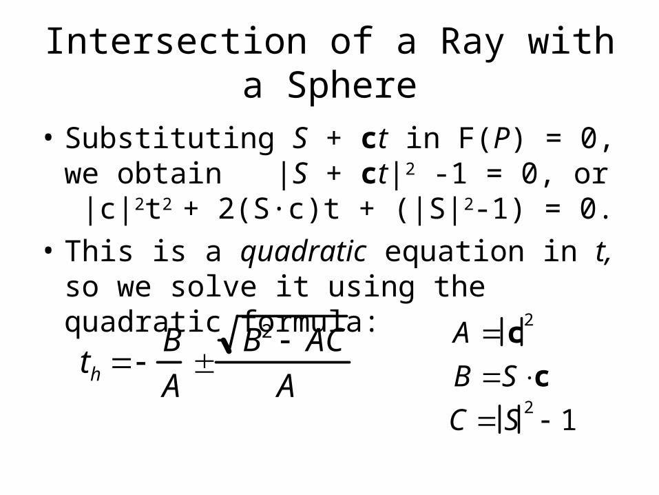
• Substituting S + ct in F(P) = 0, we obtain |S + ct|2 -1 = 0, or |c|2t2 + 2(S∙c)t + (|S|2-1) = 0.
• This is a quadratic equation in t, so we solve it using the quadratic formula:
th B
A
B2 ACA
A c 2
B Sc C S 2 1
Intersection of a Ray with a Sphere (2)
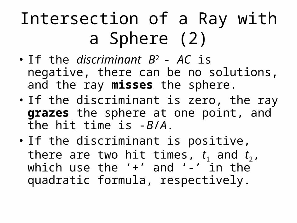
• If the discriminant B2 - AC is negative, there can be no solutions, and the ray misses the sphere.
• If the discriminant is zero, the ray grazes the sphere at one point, and the hit time is -B/A.
• If the discriminant is positive, there are two hit times, t1 and t2, which use the ‘+’ and ‘-’ in the quadratic formula, respectively.
Example
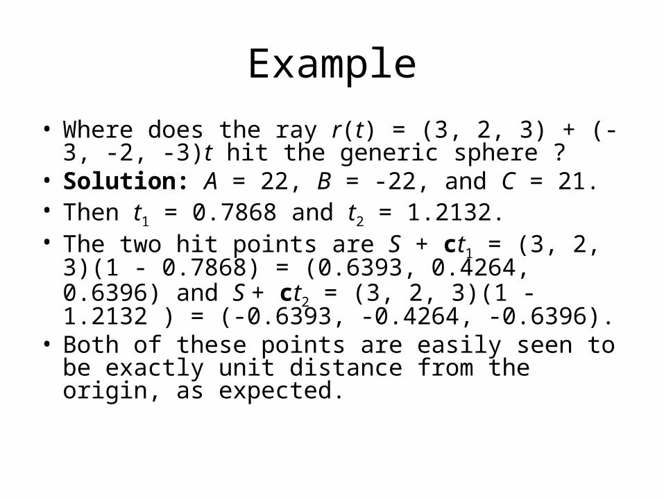
• Where does the ray r(t) = (3, 2, 3) + (-3, -2, -3)t hit the generic sphere ?
• Solution: A = 22, B = -22, and C = 21. • Then t1 = 0.7868 and t2 = 1.2132. • The two hit points are S + ct1 = (3, 2, 3)(1 -
0.7868) = (0.6393, 0.4264, 0.6396) and S + ct2 = (3, 2, 3)(1 - 1.2132 ) = (-0.6393, -0.4264, -0.6396).
• Both of these points are easily seen to be exactly unit distance from the origin, as expected.
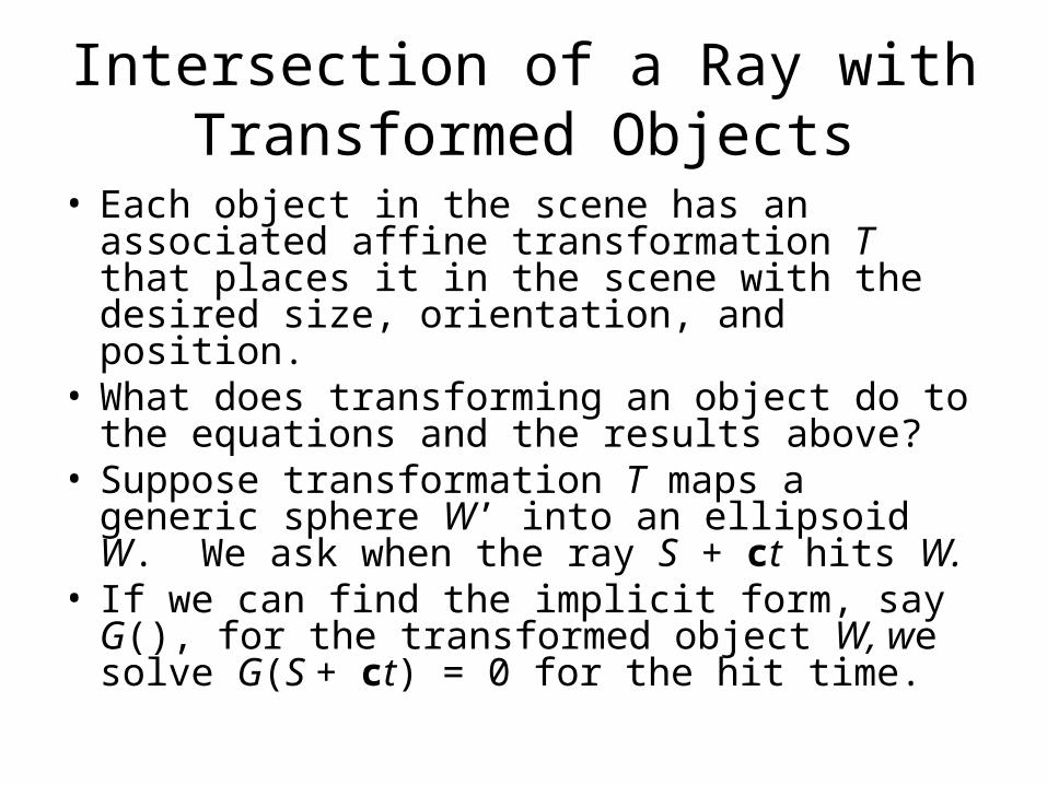
Intersection of a Ray with Transformed Objects
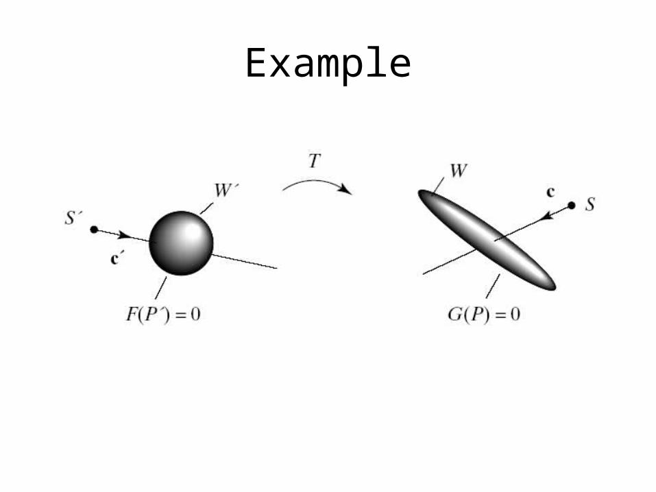
• Each object in the scene has an associated affine transformation T that places it in the scene with the desired size, orientation, and position.
• What does transforming an object do to the equations and the results above?
• Suppose transformation T maps a generic sphere W’ into an ellipsoid W. We ask when the ray S + ct hits W.
• If we can find the implicit form, say G(), for the transformed object W, we solve G(S + ct) = 0 for the hit time.
Example
Intersection of a Ray with Transformed Objects (2)
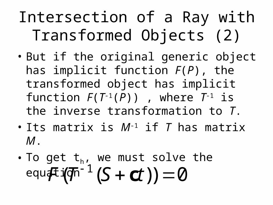
• But if the original generic object has implicit function F(P), the transformed object has implicit function F(T-1(P)) , where T-1 is the inverse transformation to T.
• Its matrix is M-1 if T has matrix M.
• To get th, we must solve the equation
F T S t( ( )) 1 0c
Intersection of a Ray with Transformed Objects (3)
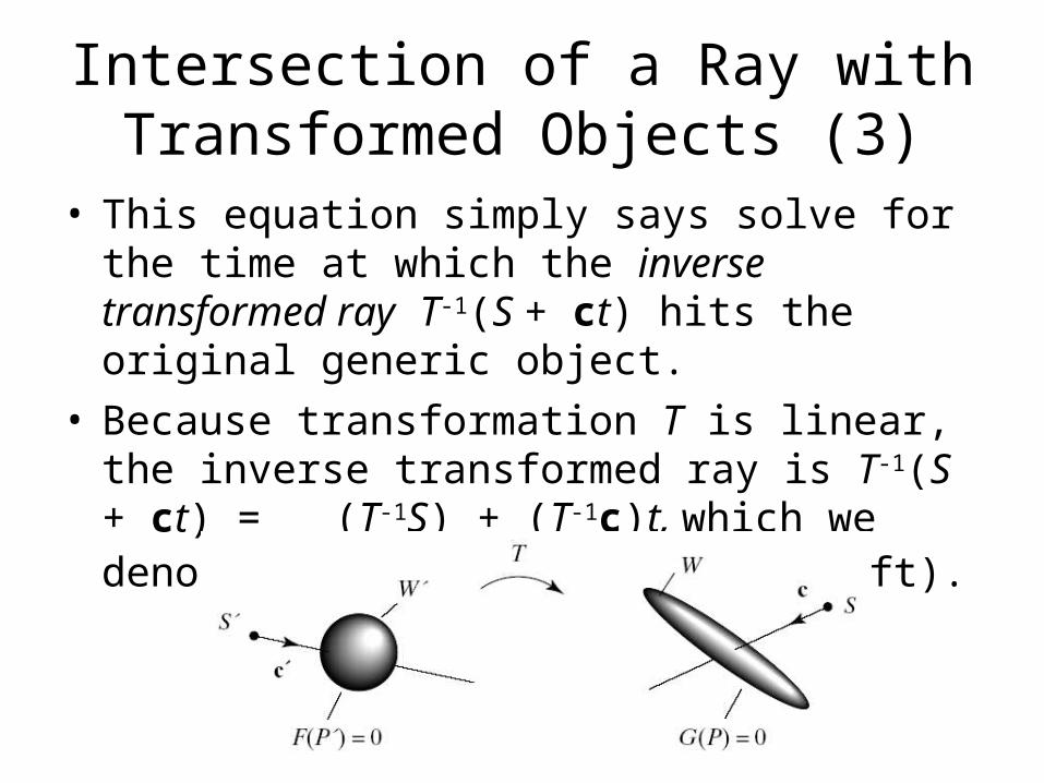
• This equation simply says solve for the time at which the inverse transformed ray T-1(S + ct) hits the original generic object.
• Because transformation T is linear, the inverse transformed ray is T-1(S + ct) = (T-1S) + (T-1c)t, which we denote as S’ + c’t in the figure (left).

Intersection of a Ray with Transformed Objects (4)
• Suppose the matrix associated with transformation T is M.
• Using homogeneous coordinates the inverse transformed ray has parametric expression
tcStc
c
c
MS
S
S
Mtrz
y
x
z
y
x
~~
01
)(~ 11

Intersection of a Ray with Transformed Objects (5)
• S’ is formed from by dropping the 1; c’ is formed from by dropping the 0.
• Instead of intersecting a ray with a transformed object, we intersect an inverse transformed ray with the generic object.
~'S
~'c
Intersection of a Ray with Transformed Objects (6)
• Each object on the object list has its own affine transformation.
• To intersect ray S + ct with the transformed object:– Inverse transform the ray (obtaining S’ + c’t);– Find its intersection time th with the generic
object;– Use the same th in S + ct to identify the actual
hit point.
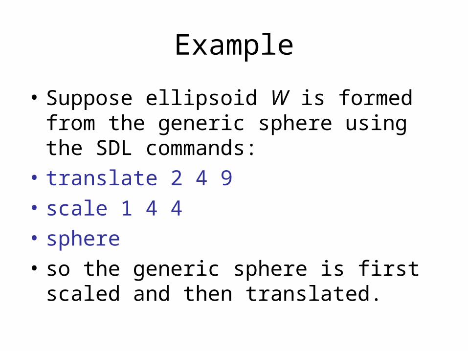
Example
• Suppose ellipsoid W is formed from the generic sphere using the SDL commands:
• translate 2 4 9
• scale 1 4 4
• sphere
• so the generic sphere is first scaled and then translated.
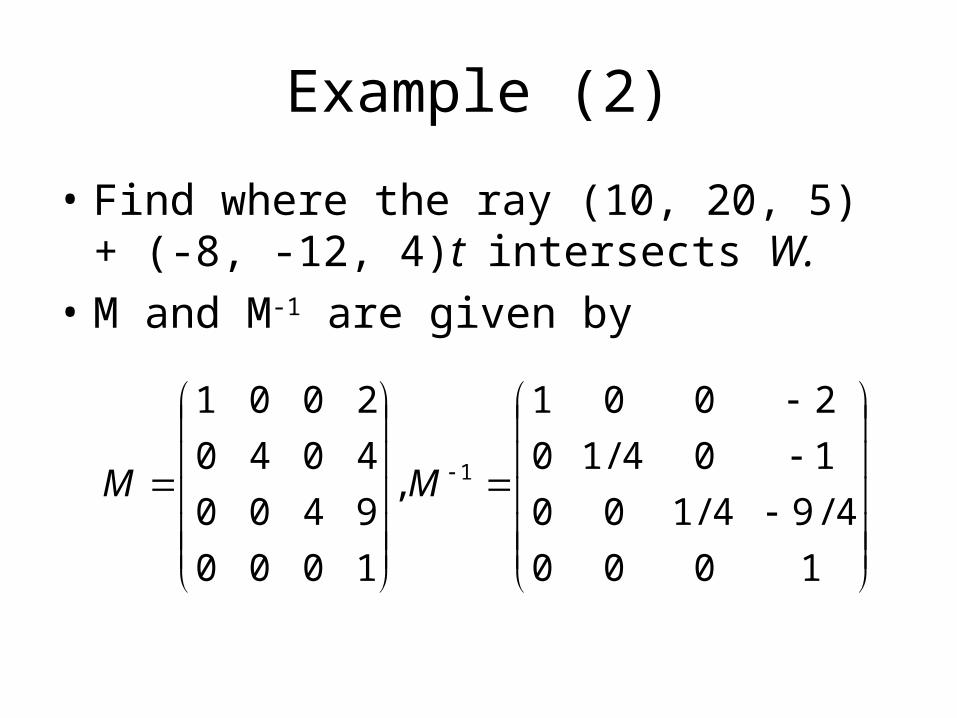
Example (2)
• Find where the ray (10, 20, 5) + (-8, -12, 4)t intersects W.
• M and M-1 are given by
1000
4/94/100
104/10
2001
,
1000
9400
4040
2001
1MM
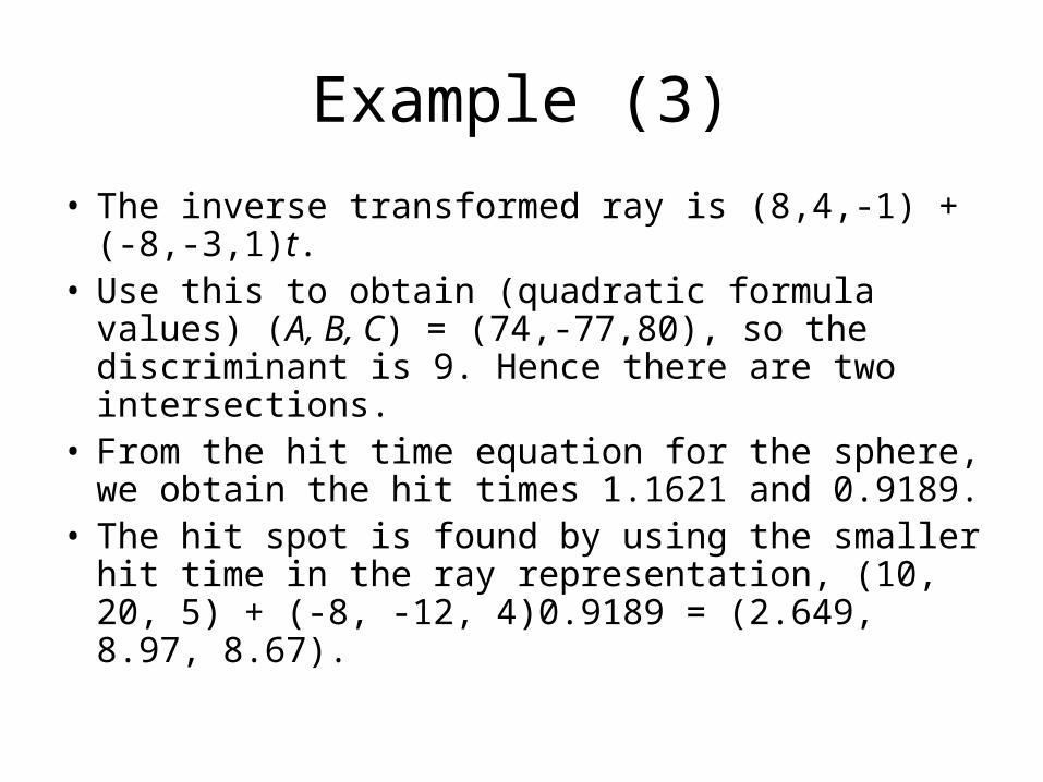
Example (3)
• The inverse transformed ray is (8,4,-1) + (-8,-3,1)t.
• Use this to obtain (quadratic formula values) (A, B, C) = (74,-77,80), so the discriminant is 9. Hence there are two intersections.
• From the hit time equation for the sphere, we obtain the hit times 1.1621 and 0.9189.
• The hit spot is found by using the smaller hit time in the ray representation, (10, 20, 5) + (-8, -12, 4)0.9189 = (2.649, 8.97, 8.67).
Organizing a Ray Tracer Application
• We can now construct an actual ray tracer. • We shall use the Scene class and the SDL
language since they provide an already constructed object list for the scene where each object has an associated affine transformation.
• A ray tracer has to deal with several different interacting objects: the camera, the screen, rays that emanate from the camera and migrate through the scene, and the scene itself, which contains many geometric objects and light sources.
Organizing a Ray Tracer (2)
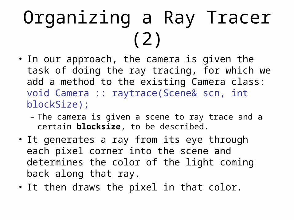
• In our approach, the camera is given the task of doing the ray tracing, for which we add a method to the existing Camera class: void Camera :: raytrace(Scene& scn, int blockSize); – The camera is given a scene to ray trace and a
certain blocksize, to be described.
• It generates a ray from its eye through each pixel corner into the scene and determines the color of the light coming back along that ray.
• It then draws the pixel in that color.
Organizing a Ray Tracer (3)
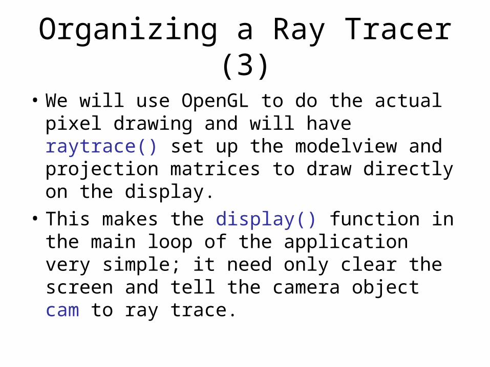
• We will use OpenGL to do the actual pixel drawing and will have raytrace() set up the modelview and projection matrices to draw directly on the display.
• This makes the display() function in the main loop of the application very simple; it need only clear the screen and tell the camera object cam to ray trace.
Organizing a Ray Tracer (4)
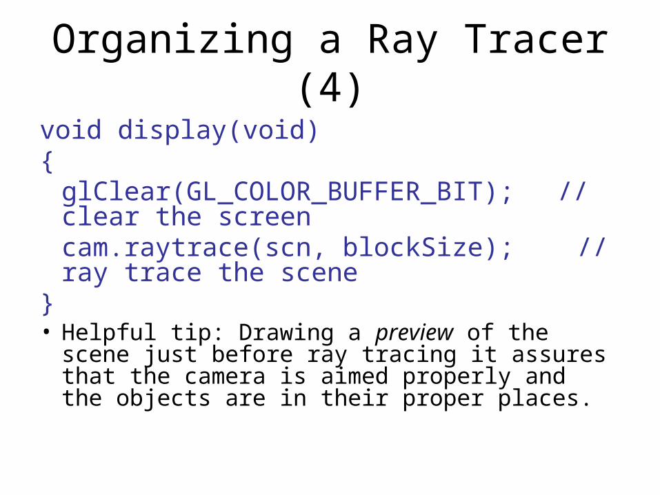
void display(void){
glClear(GL_COLOR_BUFFER_BIT); // clear the screencam.raytrace(scn, blockSize); // ray trace the scene
}• Helpful tip: Drawing a preview of the scene just
before ray tracing it assures that the camera is aimed properly and the objects are in their proper places.
Organizing a Ray Tracer (5)
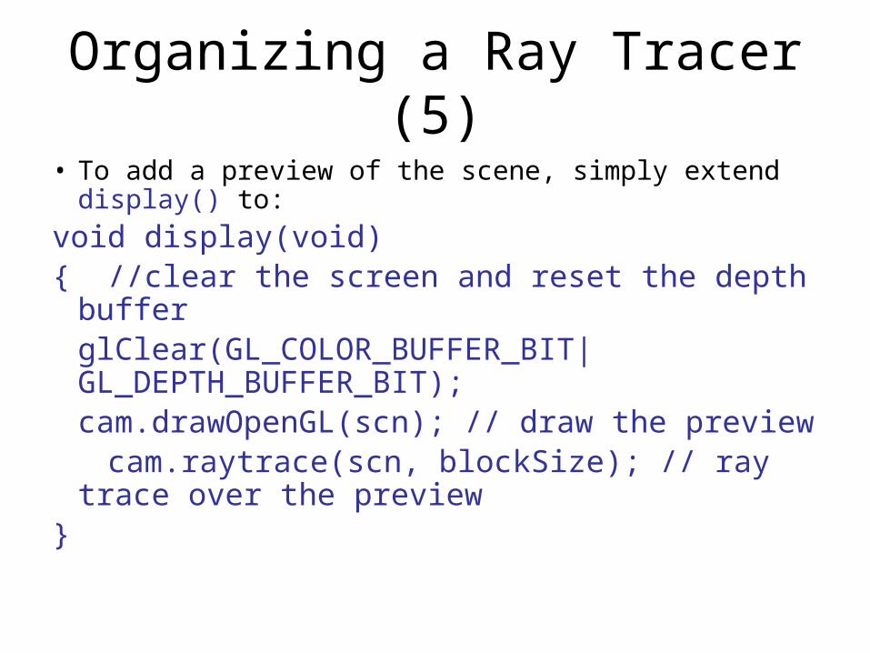
• To add a preview of the scene, simply extend display() to:
void display(void){ //clear the screen and reset the depth buffer
glClear(GL_COLOR_BUFFER_BIT|GL_DEPTH_BUFFER_BIT);cam.drawOpenGL(scn); // draw the preview
cam.raytrace(scn, blockSize); // ray trace over the preview
}
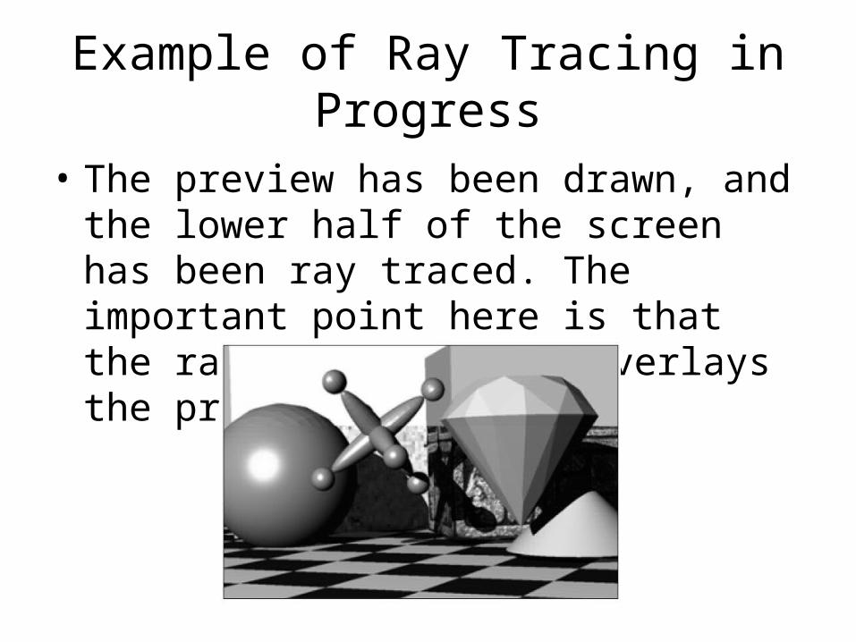
Example of Ray Tracing in Progress
• The preview has been drawn, and the lower half of the screen has been ray traced. The important point here is that the ray tracing exactly overlays the preview scene.
Organizing a Ray Tracer (6)
• The Camera class’s raytrace() method implements ray-tracing.
• For each row r and column c a ray object is created that emanates from the eye and passes through the lower left corner of the rc-th pixel into the scene.
• We need a Ray class for this.
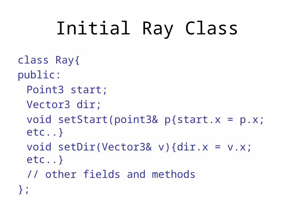
Initial Ray Class
class Ray{
public:
Point3 start;
Vector3 dir;
void setStart(point3& p{start.x = p.x; etc..}
void setDir(Vector3& v){dir.x = v.x; etc..}
// other fields and methods
};
Raytrace() Skeleton
void Camera :: raytrace(Scene& scn, int blockSize){ Ray theRay;
theRay.setStart(eye);// set up OpenGL for simple 2D drawingglMatrixMode(GL_MODELVIEW); glLoadIdentity(); glMatrixMode(GL_PROJECTION);glLoadIdentity();gluOrtho2D(0,nCols,0,nRows); // whole screen is the windowglDisable(GL_LIGHTING); // so glColor3f() works properly
Raytrace() Skeleton (2)
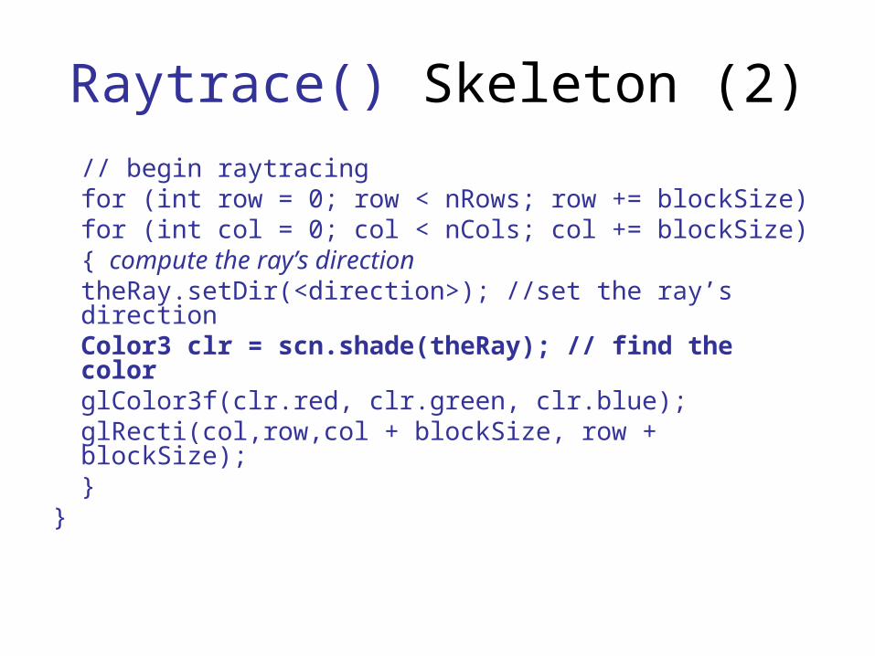
// begin raytracingfor (int row = 0; row < nRows; row += blockSize) for (int col = 0; col < nCols; col += blockSize){ compute the ray’s direction
theRay.setDir(<direction>); //set the ray’s directionColor3 clr = scn.shade(theRay); // find the colorglColor3f(clr.red, clr.green, clr.blue);glRecti(col,row,col + blockSize, row + blockSize);
}}
Organizing a Ray Tracer (7)
• The blockSize parameter determines the size of the block of pixels being drawn at each step.
• Displaying pixel blocks is a time-saver for the viewer during the development of a ray tracer.
• The images formed are rough but they appear rapidly; instead of tracing a ray through every pixel, wherein the picture emerges slowly pixel by pixel, rays are traced only through the lower left corner of each block of pixels.
Organizing a Ray Tracer (8)
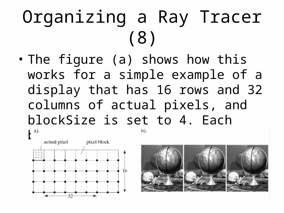
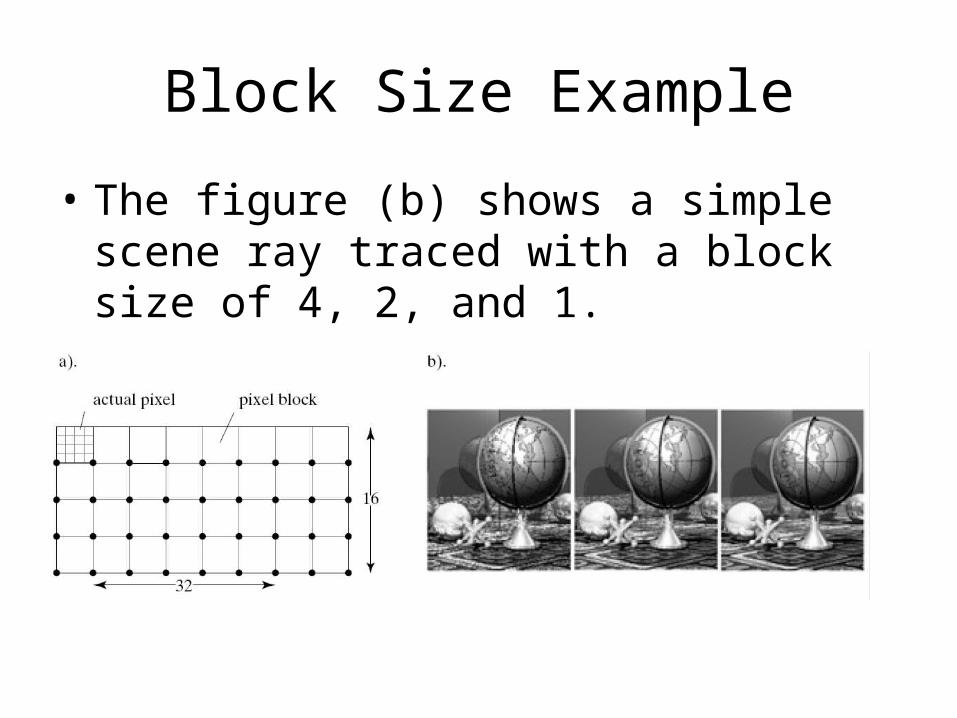
• The figure (a) shows how this works for a simple example of a display that has 16 rows and 32 columns of actual pixels, and blockSize is set to 4. Each block consists of 16 pixels.
Organizing a Ray Tracer (9)
• The color of the ray through the corner of the block is determined, and the entire block (all 16 pixels) is set to this uniform color.
• The image would appear as a raster of four by eight blocks, but it would draw very quickly.
• If this rough image suggests that everything is working correctly, the viewer can re-trace the scene at full resolution by setting blockSize to 1.
Block Size Example
• The figure (b) shows a simple scene ray traced with a block size of 4, 2, and 1.
Organizing a Ray Tracer (10)
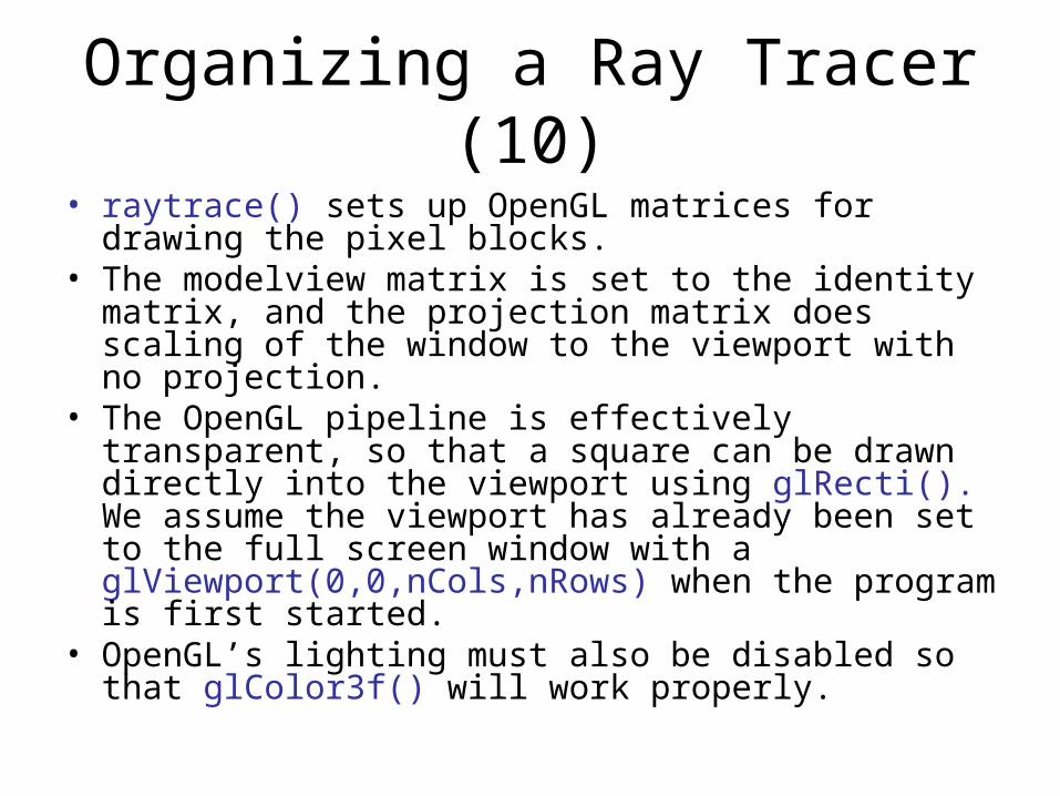
• raytrace() sets up OpenGL matrices for drawing the pixel blocks.
• The modelview matrix is set to the identity matrix, and the projection matrix does scaling of the window to the viewport with no projection.
• The OpenGL pipeline is effectively transparent, so that a square can be drawn directly into the viewport using glRecti(). We assume the viewport has already been set to the full screen window with a glViewport(0,0,nCols,nRows) when the program is first started.
• OpenGL’s lighting must also be disabled so that glColor3f() will work properly.


![Monte-Carlo Ray-Tracing for Realistic Interactive ...ogoksel/pre/Mattausch... · Current surface-based ray-tracing methods [BBRH13,SAP15] utilize a recursive ray-tracing scheme: Whenever](https://static.cupdf.com/doc/110x72/5ea7e340ac9b6076ec3acc9f/monte-carlo-ray-tracing-for-realistic-interactive-ogokselpremattausch.jpg)