DEIF A/S · Frisenborgvej 33 · DK-7800 Skive · Tel.: +45 9614 9614 · Fax: +45 9614 9615 · [email protected] · www.deif.com
DEIF A/S · Frisenborgvej 33 · DK-7800 Skive · Tel.: +45 9614 9614 · Fax: +45 9614 9615 · [email protected] · www.deif.com
DEIF A/S · Frisenborgvej 33 · DK-7800 Skive · Tel.: +45 9614 9614 · Fax: +45 9614 9615 · [email protected] · www.deif.com
DATA SHEET
Genset Control Unit, GCU 100● Engine control and protection● Generator and busbar protection● Emergency genset control● Breaker control● Easy-to-read graphical display● Integrated emulation software
solution
Document no.: 4921240428BSW version:
1. Genset Control Unit, GCU 1001.1. Variants and options...............................................................................................................................3
1.1.1. Variant overview............................................................................................................................31.1.2. Protection (ANSI) ..........................................................................................................................41.1.3. Available variants ..........................................................................................................................4
1.2. Accessories............................................................................................................................................51.2.1. Available accessories ...................................................................................................................5
1.3. Variant display layouts...........................................................................................................................51.3.1. GCU 111........................................................................................................................................51.3.2. GCU 112........................................................................................................................................61.3.3. GCU 113........................................................................................................................................6
1.4. Technical specifications and dimensions...............................................................................................71.4.1. Technical specifications.................................................................................................................71.4.2. Unit dimensions in mm (inches).....................................................................................................9
1.5. Order specifications and disclaimer.......................................................................................................91.5.1. Order specifications.......................................................................................................................91.5.2. Disclaimer....................................................................................................................................10
GCU 100 data sheet 4921240428 UK
DEIF A/S Page 2 of 10
1. Genset Control Unit, GCU 1001.1 Variants and options
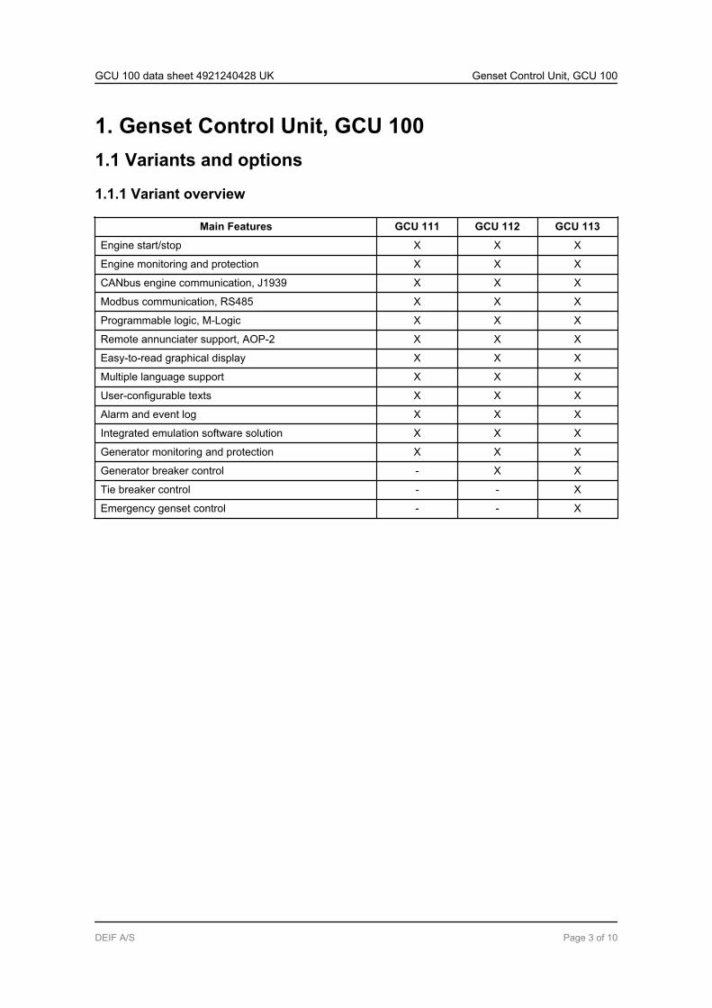
1.1.1 Variant overview
Main Features GCU 111 GCU 112 GCU 113
Engine start/stop X X X
Engine monitoring and protection X X X
CANbus engine communication, J1939 X X X
Modbus communication, RS485 X X X
Programmable logic, M-Logic X X X
Remote annunciater support, AOP-2 X X X
Easy-to-read graphical display X X X
Multiple language support X X X
User-configurable texts X X X
Alarm and event log X X X
Integrated emulation software solution X X X
Generator monitoring and protection X X X
Generator breaker control - X X
Tie breaker control - - X
Emergency genset control - - X
GCU 100 data sheet 4921240428 UK Genset Control Unit, GCU 100
DEIF A/S Page 3 of 10
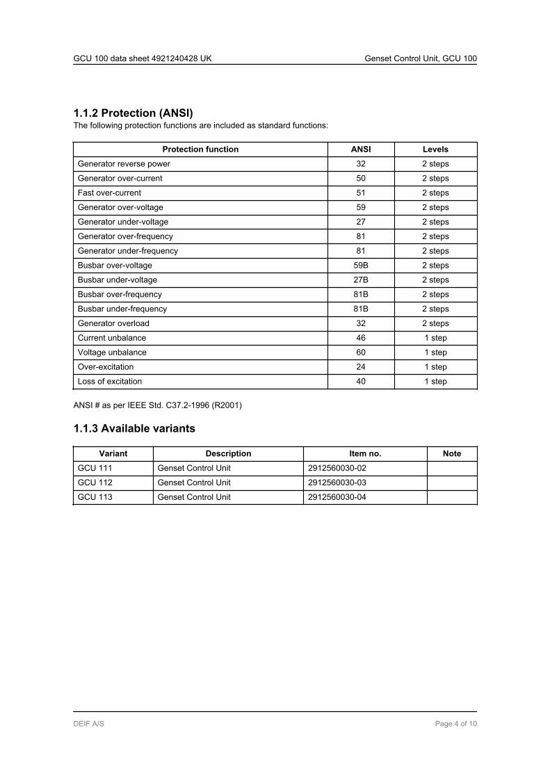
1.1.2 Protection (ANSI)The following protection functions are included as standard functions:
Protection function ANSI Levels
Generator reverse power 32 2 steps
Generator over-current 50 2 steps
Fast over-current 51 2 steps
Generator over-voltage 59 2 steps
Generator under-voltage 27 2 steps
Generator over-frequency 81 2 steps
Generator under-frequency 81 2 steps
Busbar over-voltage 59B 2 steps
Busbar under-voltage 27B 2 steps
Busbar over-frequency 81B 2 steps
Busbar under-frequency 81B 2 steps
Generator overload 32 2 steps
Current unbalance 46 1 step
Voltage unbalance 60 1 step
Over-excitation 24 1 step
Loss of excitation 40 1 step
ANSI # as per IEEE Std. C37.2-1996 (R2001)
1.1.3 Available variants
Variant Description Item no. Note
GCU 111 Genset Control Unit 2912560030-02
GCU 112 Genset Control Unit 2912560030-03
GCU 113 Genset Control Unit 2912560030-04
GCU 100 data sheet 4921240428 UK Genset Control Unit, GCU 100
DEIF A/S Page 4 of 10
1.2 Accessories
1.2.1 Available accessories
Accessory Description Item no. Note
Operator panels
Additional Operator Panel, AOP-2(X4)
16 configurable LEDs, 8 configu-rable buttons and 1 status relay.CANbus communication.
2912890050
Display gasket (L) 1129150061 Included in stand-ard delivery
Cables
USB to TTL PC interface cable(J9)
For PC utility software 1034000011
Documentation
CD-ROM with complete documen-tation (K2)
2304230002
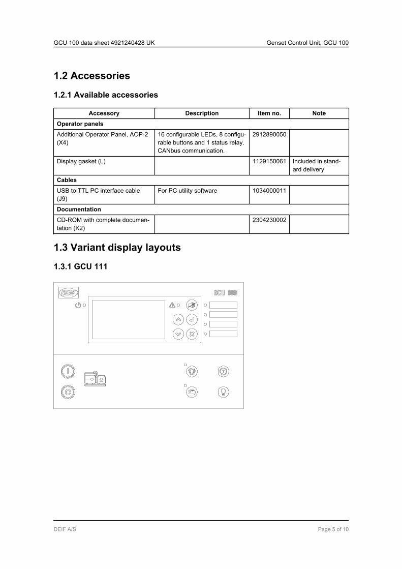
1.3 Variant display layouts
1.3.1 GCU 111
GCU 100 data sheet 4921240428 UK Genset Control Unit, GCU 100
DEIF A/S Page 5 of 10
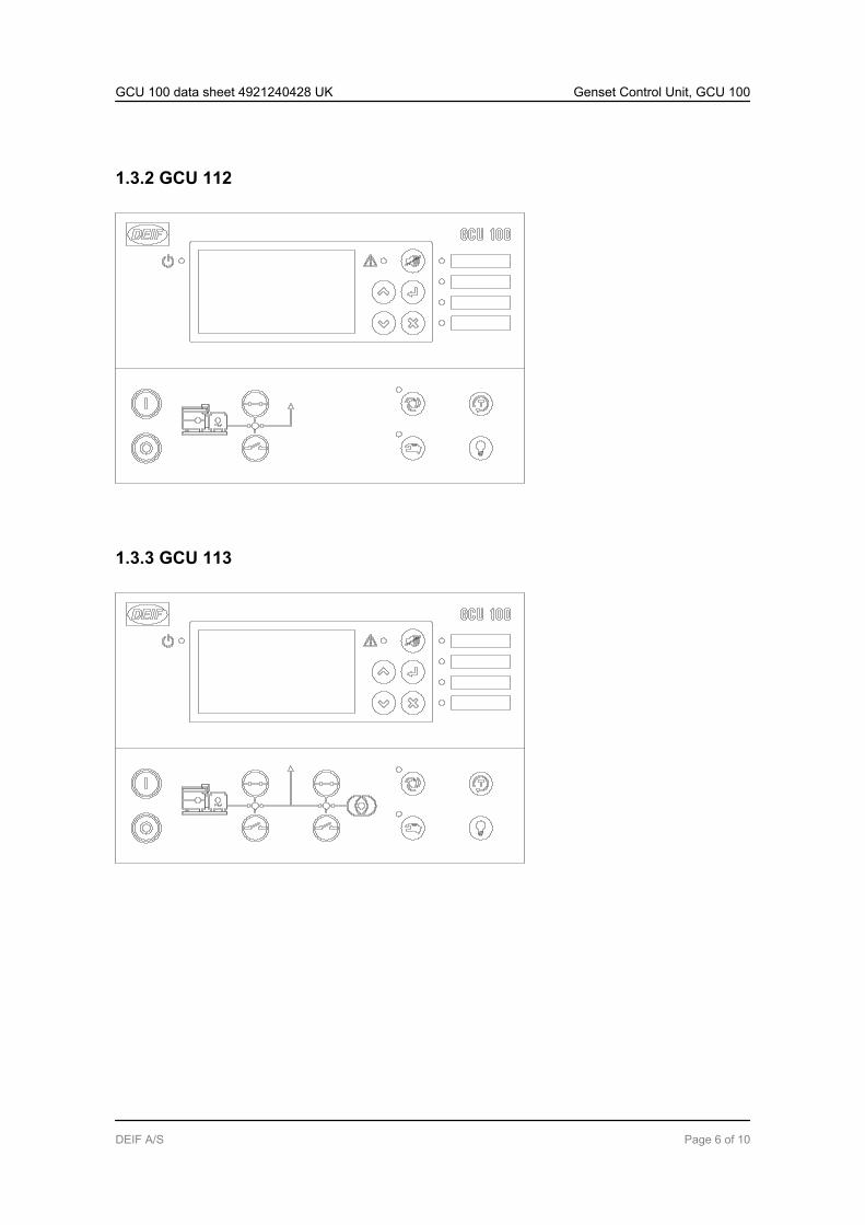
1.3.2 GCU 112
1.3.3 GCU 113
GCU 100 data sheet 4921240428 UK Genset Control Unit, GCU 100
DEIF A/S Page 6 of 10
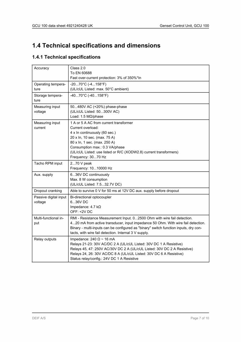
1.4 Technical specifications and dimensions
1.4.1 Technical specifications
Accuracy Class 2.0To EN 60688Fast over-current protection: 3% of 350%*In
Operating tempera-ture
-20...70°C (-4...158°F)(UL/cUL Listed: max. 50°C ambient)
Storage tempera-ture
-40...70°C (-40...158°F)
Measuring inputvoltage
50...480V AC (+20%) phase-phase(UL/cUL Listed: 50...300V AC)Load: 1.5 MΩ/phase
Measuring inputcurrent
1 A or 5 A AC from current transformerCurrent overload:4 x In continuously (60 sec.)20 x In, 10 sec. (max. 75 A)80 x In, 1 sec. (max. 250 A)Consumption max.: 0.3 VA/phase(UL/cUL Listed: use listed or R/C (XODW2.8) current transformers)Frequency: 30...70 Hz
Tacho RPM input 2...70 V peakFrequency: 10...10000 Hz
Aux. supply 6...36V DC continuouslyMax. 8 W consumption(UL/cUL Listed: 7.5...32.7V DC)
Dropout cranking Able to survive 0 V for 50 ms at 12V DC aux. supply before dropout
Passive digital inputvoltage
Bi-directional optocoupler6...36V DCImpedance: 4.7 kΩOFF: <2V DC
Multi-functional in-put
RMI - Resistance Measurement Input. 0...2500 Ohm with wire fail detection.4...20 mA from active transducer, input impedance 50 Ohm. With wire fail detection.Binary - multi-inputs can be configured as "binary" switch function inputs, dry con-tacts, with wire fail detection. Internal 3 V supply.
Relay outputs Impedance: 240 Ω ~ 16 mARelays 21-23: 30V AC/DC 2 A (UL/cUL Listed: 30V DC 1 A Resistive)Relays 45, 47: 250V AC/30V DC 2 A (UL/cUL Listed: 30V DC 2 A Resistive)Relays 24, 26: 30V AC/DC 8 A (UL/cUL Listed: 30V DC 6 A Resistive)Status relay/config.: 24V DC 1 A Resistive
GCU 100 data sheet 4921240428 UK Genset Control Unit, GCU 100
DEIF A/S Page 7 of 10
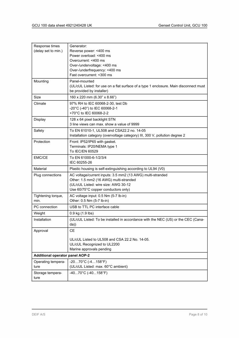
Response times(delay set to min.)
Generator:Reverse power: <400 msPower overload: <400 msOvercurrent: <400 msOver-/undervoltage: <400 msOver-/underfrequency: <400 msFast overcurrent: <300 ms
Mounting Panel-mounted(UL/cUL Listed: for use on a flat surface of a type 1 enclosure. Main disconnect mustbe provided by installer)
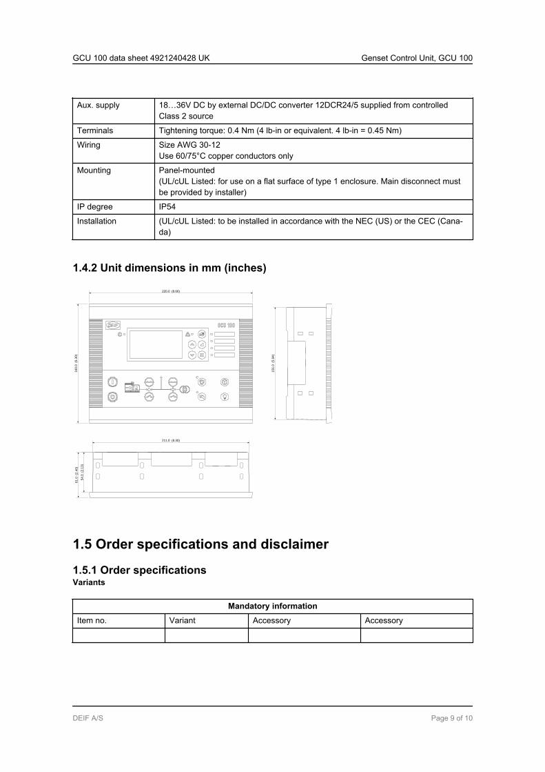
Size 160 x 220 mm (6.30” x 8.66”)
Climate 97% RH to IEC 60068-2-30, test Db-20°C (-40°) to IEC 60068-2-1+70°C to IEC 60068-2-2
Display 128 x 64 pixel backlight STN3 line views can max. show a value of 9999
Safety To EN 61010-1, UL508 and CSA22.2 no. 14-05Installation category (overvoltage category) III, 300 V, pollution degree 2
Protection Front: IP52/IP65 with gasket.Terminals: IP20/NEMA type 1To IEC/EN 60529
EMC/CE To EN 61000-6-1/2/3/4IEC 60255-26
Material Plastic housing is self-extinguishing according to UL94 (V0)
Plug connections AC voltage/current inputs: 3.5 mm2 (13 AWG) multi-strandedOther: 1.5 mm2 (16 AWG) multi-stranded(UL/cUL Listed: wire size: AWG 30-12Use 60/75°C copper conductors only)
Tightening torque,min.
AC voltage input: 0.5 Nm (5-7 lb-in)Other: 0.5 Nm (5-7 lb-in)
PC connection USB to TTL PC interface cable
Weight 0.9 kg (1.9 lbs)
Installation (UL/cUL Listed: To be installed in accordance with the NEC (US) or the CEC (Cana-da))
Approval CE
UL/cUL Listed to UL508 and CSA 22.2 No. 14-05.UL/cUL Recognized to UL2200Marine approvals pending
Additional operator panel AOP-2
Operating tempera-ture
-20…70°C (-4…158°F)(UL/cUL Listed: max. 60°C ambient)
Storage tempera-ture
-40...70°C (-40...158°F)
GCU 100 data sheet 4921240428 UK Genset Control Unit, GCU 100
DEIF A/S Page 8 of 10
Aux. supply 18…36V DC by external DC/DC converter 12DCR24/5 supplied from controlledClass 2 source
Terminals Tightening torque: 0.4 Nm (4 lb-in or equivalent. 4 lb-in = 0.45 Nm)
Wiring Size AWG 30-12Use 60/75°C copper conductors only
Mounting Panel-mounted(UL/cUL Listed: for use on a flat surface of type 1 enclosure. Main disconnect mustbe provided by installer)
IP degree IP54
Installation (UL/cUL Listed: to be installed in accordance with the NEC (US) or the CEC (Cana-da)
1.4.2 Unit dimensions in mm (inches)
16
0.0
(6
.30
)
220.0 (8.66)
15
1.0
(5
.94
)
211.0 (8.30)
61
.0 (2
.40
)
54
.0
(2.1
3)
1.5 Order specifications and disclaimer
1.5.1 Order specificationsVariants
Mandatory information
Item no. Variant Accessory Accessory
GCU 100 data sheet 4921240428 UK Genset Control Unit, GCU 100
DEIF A/S Page 9 of 10
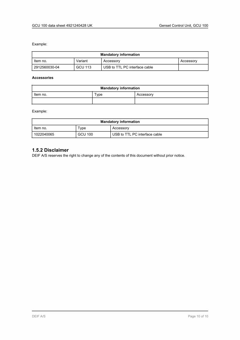
Example:
Mandatory information
Item no. Variant Accessory Accessory
2912560030-04 GCU 113 USB to TTL PC interface cable
Accessories
Mandatory information
Item no. Type Accessory
Example:
Mandatory information
Item no. Type Accessory
1022040065 GCU 100 USB to TTL PC interface cable
1.5.2 DisclaimerDEIF A/S reserves the right to change any of the contents of this document without prior notice.
GCU 100 data sheet 4921240428 UK Genset Control Unit, GCU 100
DEIF A/S Page 10 of 10