GENERAL FOUNDRY PRACTICE


GENERAL FOUNDRYPRACTICE
Being a Treatise on General Iron Founding,
Job Loam Practice, Moulding and Casting of
the Finer Metals, Practical Metallurgy in
the Foundry, and Patternmaking from a
Moulder's Point of View
BY
WILLIAM ROXBURGH, M.R.S.AM
Foundry Manager, Kilmarnock
NEW YORK
D. VAN NOSTRAND COMPANY23 MURRAY AND 27 WARREN STREETS
1910


PREFACE
MANY years' experience as a moulder and foundry managerhas demonstrated to the author the need there is for such a
book as here presented, which is based on the modern lines
of theory and practice combined, and- which contains nothingbut what has passed through the author's own hands, duringan experience of over thirty years.
The whole work is light and practical reading, and is
intended to give the greatest amount of information on
foundry methods, materials, and metals, with the least
possible study.
A book such as this, although primarily intended for
moulders and founders of every description, is also written for
draughtsmen, patternmakers, and the engineering profession
in general.
As a text book it will be most interesting to many students
of metallurgy and users of metals, who either cast or con-
struct. Nevertheless, to some it may show but little new in
founding, and probably something which may be objected to.
Still, on the other hand, there may be just as many, nay
more, to whom the book may, at least, be a source of relief in
times of difficulty, and to such, and all that are interested in
the abstruse problems of founding in its many phases is this
book specially commended.
The author thankfully acknowledges his indebtedness to
The Ironmonger for the use of the following articles, from his
pen, which appeared in recent issues of this Journal, all of
which have been more or less amended for this work :
"Starting a Small Iron Foundry," "Metal Mixing and its
217094

vi PREFACE
Adaptation/'"Starting a Small Brass Foundry,"
" Aluminium
Castings and Alloys,""Moulding for Aluminium Castings,"
^-Malleable-Cast."
Likewise, the author's special thanks are due to the several
pig-iron manufacturers whose analyses are herein recorded,
for specially preparing those analyses which in every case are
up-to-date, and specially sanctioned for publication in this
work.
Lastly, the author's thanks are also due to Mr. 0. F.
Hudson, M.Sc., of Birmingham, for assistance given in the
form of editing this work, and this particularly applies to the
chapters on "Practical Metallurgy in The Foundry
"and
" Fluid Pressure."
WILLIAM ROXBURGH.KlLMAENOCK,
January, 1910.

CONTENTS
DIVISION I
GENERAL IRON FOUNDINGPAGE
Starting a Small Iron Foundry . . . . .-.'.-
. . 1
Moulding Sands . . . . . . . ... 14
Location of Impurities . . . 23
Core"Gum . . . . . . ...... .27Blow Holes . ... 29
Burning Castings . .32Venting . . . .
" '. . . . '. . . 35
The Use of the Kiser in Casting . . . . . . . 38
Chaplets ..
. . . 42
Shrinkage. . . . . . . >.
"
. . . .44Pressure of Molten Iron (Ferro-Static Pressure) . . .
j
. 57
Feeding or the Compression of Metals . . .' . . . 63
Metal Mixing . . . . . . .'.'... 71
Temperature . . . . . . . .|.
.
"
. 79
Defects in Cast-iron Castings . . . ... . .83Special Pipes (and Patterns) Green-Sand and Dry-Sand . . 87
Core Clipping'
. ;. . 108
Machine and Snap Flask Moulding . . . .
'
. . .113Moulding Cylinders and Cylinder Cores . . . . : .116Jacketed Cylinders . . . . . ... . 125
Core-Sands .v . . 135
Moulding a Corliss Cylinder in Dry-Sand . . . . .139General Pipe Core Making . . . . . . ./ .146Chilled Castings .153Flasks or Moulding Boxes . . . . . .. .158Gates and Gating . .
*
. . . . / . . .165
DIVISION II
JOBBING LOAM PRACTICE
Loam Moulding . . . . . . . . . .173
Moulding a 36" Cylinder Liner 177

viii CONTENTSPAGE
Moulding a Slide Valve Cylinder . 1S2
Moulding a Cylinder Cover 186
Cores and Core Irons for a Slide Valve Cylinder .... 188
Moulding a Piston 191
Loam Moulding in Boxes or Casings 194
Moulding a 20" Loco. Boiler-Front Cress-Block . . . .196The Use of Ashes and Dry-Sand in Loam Moulding . . . 199
DIVISION III
MOULDING AND CASTING THE FINER METALS
Starting a Small Brass Foundry : Furnaces;Waste in Melting ;
Moulding ; Temperatures ;Brass Mixtures, etc.
;Draw and
Integral Shrinkage; Position of Casting and Cooling the
Castings 203
Bronzes : Aluminium; Phosphor ; Manganese, and running with
the Plug gate 215
Casting Speculums : The Alloy ; Draw ;Treatment of Castings ;
Compression and Annealing ; Melting and Pouring; Moulding 217
Aluminium Founding : Scabbing ;Sand
; Gating ;Risers
;Melt-
ing ;and Temperature 221
Aluminium Castings and Alloys 227" Malleable-Cast
"230
Practical Metallurgy in the Foundry 233
General Patternmaking from a Moulder's Point of View . . . 246
Foundry Ovens and their Construction 268
Fuels 274
Foundry Tools 279

LIST OF ILLUSTRATIONSFIG.
. PAGE1 . Plan of Small Foundry . . . . . ... 42. Elevation of Small Foundry . . . . . . . 43. Plan of Offices and Stores . . . . . . . . 44. Plain Top-part 7
5. End Elevation of Top and Bottom Boxes . .....' . 7
6. Pattern for Box Handles, Figs. 4 and 5 . ... . 7
7. Box-part Piece for Columns and Pipes . . . . . 8
8. Handle Pattern and Core for Crane Boxes . . . . .89. Swivel Core for ditto -. . . 8
10. Box-Bar Pattern ;. . . 811. Moulding Tub for Light Castings . . '. . . . . 9
12. 24-in. Cupola for Light Castings . '. . . . . 12
13. Marking Table Casting . . ... . . .2414. Elevation of Table Casting . . < . .... ., . 24
15. Sectional End Elevation of Barrel with Dirt Receptacle on Top 25
16. Blowhole on Topside of Pipe Casting . . < . . . 30
17. Plan of Pipe showing Blowhole . . .t
. .
"
. 30
18. Sectional Elevation showing Blowhole . . . . '*. 30
19." Burned" Shaft ; .
,. .... 33
20. Section of Shaft .3321.
" Burned" Pipe Flange .... ...:'. .' . . 34
22. Cross Section of Mould, showing Vents . ... . . 36
23. Longitudinal Section of Flange Pipe and Basins . . 39
24. Longitudinal Section of Pipe or Tube with Basins ... 39
25. Plan of Diagonal Ribbed Box . . . ... .4826. Plan of Double Diagonal Ribbed Box .
-
,
;
. ., . 48
27. Tank Plate 49
28. Square-ribbed Box . . . . . .... .4929. Cross Section of Soleplate Leg . . . ; . .5130. Cross Section of Box Soleplate Leg . . .... 52
31. Sectional Plan of Loam Cylinder Mould . . . ... 56
32. Sectional Elevation of Cylinder Loam Mould .-
. .5733. Cross Section of Mould and Box with Lifting Pressure Diagram (50
34. Section of Solid Cubes for Pressure Calculation.... 61
35. Section of Square Cube without Ends . . ... . .6236. Longitudinal Section of Double Flange Pipes .... 66
37. Section of Plate with Hollow and Solid Bosses . 68

x LIST OF ILLUSTRATIONS
FIG. PAGE38. Ingot Casting when Fluid 70
39. Ingot Casting when Solidified . 71
40. Cross Section of Pipe . . ... . . . .7741. Cross Section of Plate . . . - \ . . . .7742. Cross Section of Pipe . , .... . . . .7743. Cross Section of Plate . . . , . . . .7744. Barrel with part of Flange removed . . . . . .8145. Elevation showing Defect in Bore . . . . . . 81
46. Section of Plate in Mould with " Dumb-scab ". . . . 83
47. Vertical Cast Earn ... . .' . .
'
. -. . 80
48. Cylinder Cover (Disproportionate Metal) . .. . '.-' . 86
49. Cylinder Cover (Proportionate Metal) ... , . . 86
50. S. Pipe Core Plate (wood) . ...''. .
"..
-. 89
51. Core Sweep . . . . . . .^ . . . 89
52. Section of Core . . ... *. . . . . 89
53. Flanged Skeleton Pattern . .-, . *. . ; . . 89
54. Mould Sweep . . . , '. .:
. . . . 89
55. Air Vessel Pattern (Boss) . . . . , . ,:
. 92
56. Section of an Air Vessel Coie . .. , .. ... . 94
57. Longitudinal Section of Bottle-necked Pipe'
. . ^ . . 96
58. Bell-mouthed Pipe . . . . . . .-
. . 97
59. Stool Bend Pipe ~,. ..... . 100
60. End Elevation of Stool Bend . . ". .
',
. . . .10061. Core Iron and PIate for Bend Pipes . '.
.'. . . .101
62. Cross Section of Core . . .-'.'.. . . . 101
63. Cross Section of Plate and Half Core . . -, ' 101
64. Longitudinal Section of Pump Pipe Box, Mould and Core, etc. 104
65. Longitudinal Section of Pump Pipe cast on " The Bank ". . 106
66. Gates and Risers on Flange . .... . . . 107
67. Cross Section of detached Core Clips (double) . . . . 109
68. Core Clips attached . . . .- * . , .;
. Ill
69. Cross Section of Core Clips attached (double) ..,
~
. . 112
70. Longitudinal Section of Cylinder with Sinking-head . . . 122
71. Cross Section of Cylinder with Arrows on Spongy Parts . .12372. Sectional Elevation of Jacket Cylinder Core before Dressing, etc. 128
73. Corliss Cylinder (half pattern) in Moulding Box . . . 140
74. End Elevation of Corliss Cylinder Box Mould and Cores . . 141
75. End Elevation of Corliss Cylinder Cores . . . \. . 143
76. Exhaust Cylinder Core joining Port Cores at Arrows ;. . . 144
77. Plan of Bend Pipes without Stangey .- > . . . 148
78. Section of Bank Pipe Core . .1-19
79. Part of Cross Section of Vertical Pipe Core Bar . . , . . 152
80. Elevation of Chilled Anvil Mould . . -. . . . 153
81. Plan of Top-Part for Half-wheels, etc. . . . ,. . 160
82. Segment Pattern of Pulley Box . . ._ . . . ,. 161
83. Five-part Box with Mould . ... . . . ./. 162

LIST OF ILLUSTRATIONS xi
FIG. PAGE84. Half-Duplex Vertical Pipe Casing 163
85. Sectional End Elevation of Pipe Casing 163
86. Small Wheel with Worm Gate 166
87. Spur Wheel with Fountain Gate 167
88. Loam Condenser with Bottom Gates . . . . .16989. Loam Cross with Spindle . . . . . . . 1 73
90. Plan of Cross and Spindle . . . . . . .17391. Sectional Elevation of Cylinder Liner 178
Bottom Cylinder Liner Plate Drawn off on " Bed" . . .178Bottom Bearing Sweep for Cylinder Liner . . . .179
,94. Top Cake Sweep for Cylinder Liner 179
95A. Top Cope Gauge for Cylinder Liner 179
95B. Core Gauge Stick for Cylinder Liner 179
96. Cylinder Liner . 180
97. Sectional Elevation of Cylinder Liner Top Cake . . .18198. Sectional Elevation of Slide Valve Cylinder Loam Mould . 183
99. Plan of Bottom Plate and Building Eings for Slide Yalve
Cylinder 183
100. Sweep Stick for Bottom Bearing of Slide Yalve Cylinder . .184101. Gauge Stick for Steam Port Core .185102. Exhaust Core for Slide Yalve Cylinder 185
103. Sectional Elevation of Cylinder *Cover 186
104. Sweep Stick for Cylinder Cover 187
105. Sweep Stick for Cylinder Cover Top Cake . . . .187106. Section of Steam Port Core Box 189
107. Plan of Core-iron for Steam of Slide Yalve Cylinder . .189108. Sweep Stick for Steam Port Core Box 189
109. Section of Lightening Core Box 189
110. Section of Exhaust Port Core 190
111. Section of Steam Chest Core Box and Core . . . .190112. Sectional Elevation of Piston Loam Mould .... 191
113. Piston Top-Cake Sweep . . . . . . .192114. Piston Bottom Board . 192
115. Piston Plug Core Box , . .192116. Web or Arm Board for Piston .... . . .193117. Plan of Piston showing Gates and Plug-holes . . . .193118. Plan of Core-irons for Piston 193
119. Sectional Elevation of Piston and Moulding Box . . .195120. Plan of Cress-Block and Moulding Box 196
121. Elevation of Cress-Block and Moulding Box . . . .197122. Circle Sweep for Cress-Block 198
123. Plan of Sweep for Cress-Block 198
124. Guide for Sweep Fig. 123 Cress-Block . . 198
125. Skeleton Pattern Curve for Cress-Block 199
126. Sectional Elevation of Brass Furnaces 204
127. End Elevation of Brass Furnaces 205

xii LIST OF ILLUSTRATIONSFIG. PAGE128. Cross Section of Moulding Tub for Brass Foundry . . . 20G
129. Elevation of Brass Casting and Moulding Box, showing Shrink
Cavities (vertical position) . . . . . . .211130. Sectional Elevation of Box and Casting (horizontal position ; . 212
131. Section of Speculum, showing Shi ink Cavities. . .218132. Section of Speculum (Improved Density) . . . 219133. Tensile Test Bar . . . 245
134. Sectional Elevation of Cast-iron Spigot and Faucet Pipe Pattern 248135. End Section of Cast-iron Bank-pipe Core-box.... 250136. Longitudinal Section of Shell Stucco Pattern . . . 254137. Sectional Elevation of Stucco Block Board and Sweep . .254138. Longitudinal Section of Stucco Faucet Mould.... 255139. Sectional Elevation of Stucco-Block and Sweep . . . 25 H
140. Iron Frame for Sweeping Spigot and Faucet Pipe-Mould . 259141. Body Sweep . ... . I . . 260142. Eevolving Faucet Sweep .
'
. ... . 260143. Pivot Frame Sweep for Fig. 142 .... . 260144. Elevation of Mould Sweep . . .2(51145. Elevation of Core Sweep .... 261146. Cross Section of Core, Mould, Sweep, and Box . . 2(51
147. Sectional Elevation of Eeduced Mould and Original Pattern . 2(i:j
148. Elevation of Cutting Stick for Spur-Wheels .... 2(54
149. Sectional Elevation of Increased Mould and Original Pattern . 265150. Sectional Elevation of Eeduced Capped Spur Wheel and Original
Pattern . .-
. . . . . .o
( j ( ;
151. Sectional Elevation of Increased Capped Spur Wheel and
Original Pattern . .; . . '.' . .
'
. 268152. Sectional Side Elevation of Foundry Oven Fire v 270153. Sectional Elevation of Oven Eoof . . . 271154. Front and End Elevation of Moulder's Beam . 2X0155. End Elevation of ditto . . . 280156. Stirrup Hook for Swivel Boxes . 2S1157. Cast Iron Clamp . . .-. 282158. End Elevation of Einger and Binder . . . 2S3159. Cross Section of Stool ... . 2S4160. Screw Hook for Slinging Cores, etc. . ... 2S5161. Double Shifting Hooks . . . 286

FACTS ON GENERALFOUNDRY PRACTICE
DIVISION I
GENERAL IRON FOUNDING
STARTING A SMALL IEON FOUNDRY
THE starting of an iron foundry may seem at first sight to
many a simple affair, but bearing in mind the wide range of
a jobbing foundry's requirements in matters of convenience,
site, and equipment it will be found to involve a great deal of
careful thought and consideration.
Small foundries are to a great extent in city life a thing of
the past, but here and there the necessity arises for such,
especially in a thriving agricultural district;and such foundries
are still, and always have been, an indispensable adjunct to
a successful country engineering works. It is not intended
to choose any particular class of founding, or to go deeplyinto the question of the amount of capital required for startingbusiness on the lines suggested, but simply to try to outline
what sort of foundry is required for an output of 5 or 6
tons per week of jobbing castings, under normal conditions
such as are known to practical men. In the event of the
would-be foundry master deciding to build, the judiciousselection of a suitable place for the foundry is of paramountimportance. The cartage or handling of all raw materials,
such as sands, coal, coke, pig iron, etc., and the finished pro-
duct, castings, is a serious item in the working expenses of a
foundry, and means money lost or won in proportion to the
care exercised in selecting the best possible site. Other thingsF.P. K

2 PACTS ON GENEEAL FOUNDRY PRACTICE
being equal, this point has the greatest possible influence in
determining the success or failure in the working of foundries
whether large or small.
In the foregoing we have many reasons influencing the
position of the building, but along with these we must studythe conditions below the surface. Many have unwittinglybuilt foundries, especially of the class doing heavy work,
where pits for casting are an absolute necessity, and have
found to their cost afterwards that a great mistake had been
made through want of care in selecting the site. At the first
digging of a pit they have been surprised by encounteringwater at a depth of 4 or 5 ft., which throughout was
troublesome, and before such pits could be made secure iron
tanks suitable for the work in hand had to be made and sunk,
thus securing absolute freedom from water. Hence all foun-
dries should be drained thoroughly round their outsides to a
depth sufficient to discharge automatically any water in the
floor. The lowest level of the floor should, if possible, be
taken from the highest level of the water, and if there be
3 ft. between this and the highest floor level, and more is
required, the top level of the floor should be raised to give the
required depth. In some cases such an arrangement would
prove an advantage, since cupola slag and other rubbish could
be dumped round the outside walls of the foundry. Of course,
where moulding is entirely of the turnover or machine class,
and no bedding-in is done, drainage is of no consequence
practically.
Building. The next point to decide is the structure, whether
it shall be of wood, brick, stone, or iron, or a combination of
all these materials. This question is often settled by the
amount of capital available, but whatever the structure be, it
must be wind and water-tight, as it is of the utmost import-ance to protect moulds from rain or frost, while with a dry
atmosphere is as troublesome to some green-sand moulders
as excessive dampness and cold. If all the work done in
green-sand by moulders in large or small foundries could be
executed at a uniform temperature of about 50 or 60 Fahr.,
the advantages to be gained from such conditions of workingwould more than meet the outlay attending the heating of

STARTING A SMALL IRON FOUNDRY 3
some of our large foundries in winter, while in not a few cases
the cost of improved ventilation would be more than com-
pensated for during the summer months by increased output.
It is an undoubted fact that the better the conditions under
which men have to work in the foundry, the greater are the
profits to the employer for wages paid, other things being equal.
Water. Having duly warned the intending ironfounder
against an excess of water, we now proceed to insist upon a
sufficient supply, for this is indispensable in the foundry for
watering and mixing the sand after castings have been taken
from the floor, and for use in the making of loams, etc. If
steam be the motive power of the works the cost of water for
boiler feeding purposes is also a matter for serious considera-
tion. Water, then, at even the cheapest possible rate meansmuch in the foundry. The advantages of starting a small
country shop in a good agricultural locality, where it is possibleto build near a running stream, and yet at the same time to
be free from risk of trouble with the foundry floor, will be
obvious, but the opportunities of so starting are few. Wheresuch a plan is practicable, all motive power for blast, etc.,
could be secured by the use of a water wheel or turbine, besides
having an abundant supply of water for all foundry purposes.Such an arrangement of the foundry would go a great wayin compensating for the inconvenience of country situation
when compared with the production of castings in a city
where rents and taxes are abnormally high.
Fig. 1 shows the ground plan of a foundry, 40 ft. by28 ft., which should give ample room for the production of
5 or 6 tons of jobbing castings per week. This output is
computed on the basis of alternate-day meltings, but it maybe considerably increased by casting daily. Some small shopsdo well on the former, others may do better on the latter ; it
is all a question of how far it may concern individual cases,
having regard to circumstances and economy. In Fig. 1, A is
the derrick crane ;B the cupola and spout or runner, led inwards
through the wall of the foundry; C is the stove for dryingcores and moulds ; D the fire-hole ;
F the small shop suitable
for making cores, mixing sands, shelving core-boxes and
patterns, and containing the core-stove E ; G are columns for
B 2

FACTS ON GENEEAL FOUNDRY PRACTICE
!!
'
xA
carrying the structure ;H the moulding-tub ;
I the smithyand dressing shop ;
J (Fig. 3) is the office;K the clay mill
shed ;L the pattern shop and store. Fig. 2 shows the
columns G with the traverser-bracket M cast on. These
details are only the bare outlines, and the offices attached mayor may not be required. Whatever motive power is decided
upon care must be taken to see
that the fan shall be placed to
blow as directly as possible at,
say, a distance of 20 or 30 ft.
from the cupola. On the ques-tion of materials for the con-
struction, the most up-to-date
plan is to begin by plantingthe columns on concrete or
stone foundations at suitable
distances, to ensure safetyfor carrying the roof. These
columns are usually H section,
and are made with suitable pro-
jections or brackets for carryingthe rails of the traverser crane.
The brackets add but little to
the cost of the columns, and
may either be cast on, or pro-vision may be made for boltingthem on at some future occa-
sion. This is a matter for con-
sideration at the outset even
if a "traveller
"is not then
put in.
With a foundry on a still smaller scale than the one wehave before us an H joist or beam might be erected in line
with the spout of the cupola across the shop after the fashion
of an overhead rail. A block and tackle fixed on this, and
capable of being shifted sideways, would in some measure
meet the want of crane power incidental to a small country
shop. But with the foundry built of columns, as shown in the
end view (Fig. 2), and with sides and ends either brick or
1 o I
FIG. 1.
FIG. 3.

STARTING A SMALL IRON FOUNDRY 5
corrugated iron, a small " traverser"could be placed on rails
suitable for the heaviest box or ladle likely to be in use.
A derrick crane requires substantial walls for binding the
crane thereto, but this is not the case with the traverser
because there is no side thrust set up by its working. In the
ground plan (Fig. 1) we have only shown two doors first, the
large door on the side next the cupola B, and second, the door
on the side wall of the smithy and dressing or fettling shop.
For obvious reasons the sizes are not specified, and others
may be arranged for whenever such may be thought necessary.The Foundry Floor. To a practical moulder this does not
present many difficulties;he would simply clear out the bottom
to the depth required, and so prepare it for the floor sand.
The question of the cost and quality of moulding sand, how-
ever, is an important one when starting a new foundry, and
much depends on local conditions and the distance of the pits
or quarries from the foundry. In selecting a sand or sands for
moulding no particular lines can be laid down for the guidanceof the non -practical man. A sand suitable for one class of
work may possess all the properties which go to make a goodsand for moulding in the eyes of some men, and yet might be
condemned for the same class of work by other and equally
good moulders. Such is the prejudice of experience gainedunder different conditions. However, the distinctive qualities
for practical moulding are plasticity and porosity. The sands
best known in the British Isles may be said with comparative
safety to be "London,"
"Belfast," and " Scotch rock." Equal
parts of these sands would make a fairly good floor for general
work, and if we keep to the distinctive characteristics given,it matters not whether it be black, brown, red, or yellow, the
safety of selecting a sand for moulding purposes is practicallyassured. The dividing lines between green sand, dry sand,
facing sands, etc., are fully dealt with in "Moulding Sands,"
(p. 14). Hence' it will be observed that, while the sands
as suggested are stipulated as a guide for the making of
a foundry floor, it nevertheless leaves the way clear to adaptwhatever sands may be locally accessible for mouldingpurposes.
In order to start the operations of moulding, the floor may

6 FACTS ON GENEEAL FOUNDEY PEACTICE
be filled to a depth of 9 to 12 ins., and, should a greater
depth be required for special work it is only a matter of
digging, additional sand being added from time to time as
required for such work. This method of forming a floor for a
small foundry is perfectly good, but must not be taken as
applying to foundries that are intended for heavy work, in
which case depth would be controlled according to work
anticipated. But, whether with large or small foundries, floor
making is really the result of work done and the methods of
doing it. Moulding sand is generally computed for at
1 cwt. per cubic foot when compressed by ramming ; but in
view of the moisture, etc., in it, this is but a rule-of-thumb
way of making the calculation. Fifty or sixty tons of sand
might suffice for forming the floor of the shop in question.
Under such circumstances the floor would be in a virgin
condition and comparatively free from coal dust or other
carbonaceous matter. Therefore 10 to 15 per cent, of coal
dust properly mixed with it would be an advantage. This is
not imperative, because this proportion of coal dust could be
added to each batch of facing sand until the floor had developed
by the process of casting.
Cranes and Boxes. In the selection of plant for a jobbing
foundry, some idea must be formed of the work likely to
be done. Something has already been said about crane
power. A derrick with the capacity for lifting 2 or 3 tons
should, in a general way, do all that is required. It mayeither be of wood, steel, or iron, of T, L, or H sections plated.
It should have quick and slow motions, which are preferablewith hand-power cranes. If, howewer, the crane is smaller
than suggested, a single-geared motion midway between the
ratios of a quick and slow type will prove cheap and handy.In the matter of boxes, everything depends upon the nature
of the shop and work to be done in it.
Although here and there an odd wooden flask may be found,
iron flasks are almost exclusively used in this country. In
America, on the other hand, the use of wooden flasks was
until recently practically universal ; but the iron flask is now
becoming very popular, and has in some cases entirely super-seded the wooden flask. Whether of wood or cast iron, the

STARTING A SMALL IRON FOUNDRY
I
Du FIG. 4.
design of boxes is much the same, although the details of
construction vary considerably. It will be assumed that the
boxes are to be cast in the usual way, and a few leadingfeatures illustrated. Thus, Fig. 4 shows a top-part box 2 ft.
by 2 ft. by 6 ins. ; Fig. 5, both the drag and top part in endelevation
; while Fig. 6 represents the handle pattern, whichis simply entered from the inside, as may be noticed in both
parts of Fig. 5. When ram-
ming up the bars of Fig. 4, placea trowel, or something else
suitable, over the four holes in
the pattern, and thus save the
sand from finding its waythrough and wasting the handles
during the process of rammingup the box bars, as seen at
Fig. 4. Of course the handles
might be made of wrought iron;
but if this were done, f in. or
| in. -extra thickness of metal
would need to be added wherethe dotted lines are shown in
the top and drag of Fig. 5. In
making this pattern the bars
should be made up with screws,
so that the outside frame mightbe used to make both halves
economically by transposing the top bars to the bottom, or
vice versa.
Crane work in the smallest of foundries is often indispen-
sable, and therefore crane boxes must be employed at times.
With this class of box plant, if a foundryman understands his
business, the cost of pattern-making can be kept at a minimumby ignoring the principle of complete patterns. For instance,
for large, square, or oblong boxes, the whole or part of the
outside frame may be bedded in the floor to the size wanted.
With an outside frame and two or three parallel bars runninglengthwise, and set to the length of bars wanted, and three
or four more cross-bars of the length indicated, a moulder

FACTS ON GENEEAL FOUNDKY PEACTICE
who knows his work will make boxes of this class to any size
with greater ease and economy than from a complete pattern.
All internal bars should be chamfered on the lower edges, and
be kept f in. or f in., as the case may be, less in depth than
the outside frame of the box (see Fig. 5).
Again, small foundries, such as the one we have in mind,
make occasionally a few columns ; and, indeed, the capacity of
such a shop is ample for casting, if need be, two per day, say
15 ft. long, provided the weight does not exceed the melting
capacity of the cupola. If the core-stove should not be long
enough for drying a full-length core, it could be made
Fid. '>. FIG. H>.
FIG.
conveniently in two separate lengths, a
method not at all uncommon in jobbing
moulding shops.
Fig. 7 represents a column box which
might be cast in sections, one body and two ends the three
parts being fitted together to make it Irandy for lengthening if
required. A column box, however, is better cast in one piece
where repetition work is assured; consequently it becomes a
matter for decision as to which is the more economical in the
way of present requirements or prospective business. Handles
and swivels (A, A and B in Fig. 7), either or both of which maybe used, should be "
cast on," or wrought-iron ones may be
employed. If cast iron is adopted and this is, as a rule, the
handiest and cheapest way Figs. 8 and 9 show how the core-
blocks are formed. These, when taken from the box in which
they are rammed up, are blackwashed, dried, and planted at
A, A, B (Fig. 7) during the process of moulding. Fig. 8, C,
shows how the handle pattern should be cut in halves for the
convenience of "drawing." Fig. 10 is a sketch of the box

STAETING A SMALL IEON FOUNDEY 9
bars, in moulding which a set may be fitted in the patternframe of the box at 6-in. centres, or three or four loose bars
may be used and shifted during the moulding of the boxes
after the fashion already referred to with the larger ones,
D is known as a stangy bar, and is made of flat iron, cast in
the box, as shown at Fig. 7.
Tub Moulding. Fig. 11 shows a moulding "tub" for small
work, for use with which it is necessary to have light and
handy boxes. Much might be said for tub moulding as againstfloor moulding ;
but as it is intended in this work on FoundryPractice to deal with things in the most concise way possible,
it can only be referred to as an auxiliary method which relieves
the ordinary light and medium greensand moulding, andallows better organisation. It may be said, however, that with
a tub the moulder gets about
his work in a way not possible
when moulding on his knees
on the floor. He has better
light, and can handle himself
and his work to much greater
advantage ;his sands are
more select, and the manysmall tools employed in the
moulding of this class of work are always within his reach.
These conditions all combine to give better work, and more of
it, than is possible with the same class of work on the floor.
With a tub there should be boards suitable for the sizes of
boxes, as the boxes have no bars cast in them : the boards are
indispensable for the handling of the boxes, thus removing all
danger of damage to the bottom box when placing it on the
floor for pouring. The tub should be made of wood, as
represented in Fig. 11, its length being anything from 4 ft.
upwards.Boxes. Three good sizes are 10 ins. by 10 ins. by 4 ins.
;
18 ins. by 12 ins. by 5 ins.;15 ins. by 11 ins. by 5 ins. They
should be light, and the smallest size may have handles of
| in. round iron cast in them. A better job, however, is
made when the sides are drilled and the handles fitted.
These should be made to template, and the pins turned,

10 FACTS ON GENEEAL FOUNDEY PEACTIOE
and all made interchangeable. However, small boxes of, say,
12 ins. to 18 ins. square may be cast with bow handles, which,
of course, are made with cores, in the same way as the
handles AA, Fig. 7, and snugs with cast-iron pins cast on one
half and snugs with pin holes on the other. This method of
making a box does away with machining and fitting, and maybe adapted to plate moulding, where only a flat surface top
part is required. The latter type is, of course, of special
design.
Cupolas and Melting. It is generally admitted that no
branch of foundry practice is of more interest than that
which belongs to the cupola. A good going cupola is the
backbone of a foundry, and without such no place can ever
be made to pay. In these days we have so many ideas in the
market, all ostensibly for melting at the cheapest rate
possible, that to the inexperienced man it becomes a bit of a
puzzle to know what to do for the best.
It is a matter of no particular moment whether we regard,
for the purpose of the foundry in question, a cupola with
blast belt and its distribution of tuyers, or one or two
blowing direct from the fan as previously suggested. We have
seen many fakes of cupola shells, made from old boiler shells,
or such like, that the cost of a cupola on those lines need
not be taken too seriously. Indeed, the author has seen much
good work done with a cupola of the dimensions of Fig. 12, the
shell of which had been made of such material. This cupolawas blown by a fan of very primitive type which had onlyfour blades, and yet such a contrivance gave out a blast
pressure of fully 10 ins. W.G. through a 6-in. pipe. Undernormal conditions metal came down within ten or fifteen
minutes after blowing.It is not necessary for the present to go into the details of
tuyer belts and their proper distribution, or to discuss the utility
of receivers which are said to be capable of melting more metal
at a greater heat with a less consumption of coke than is
possible with the old style of cupola practice. But the chief
precaution to be observed in designing cupolas is to secure
simplicity of form, combined with a capacity for giving the
greatest possible melt at the least possible cost. In buying a

STARTING A SMALL IRON FOUNDRY 11
cupola there is great need for care, lest the unwary be over-
persuaded by the specialist who has a habit of promising that
he can melt iron for next to nothing. In contracting for a
cupola it should be specified that the iron melted shall be of
the maximum of heat for the different moulds common to the
work of an ordinary jobbing foundry. If this be not
definitely stated at the outset, buyer and seller may disagree
in the end, when perhaps it is too late for the buyer to obtain
redress.
Modern cupolas have double-row tuyers, triple-row tuyers
and serpentine tuyers, all of which may or may not have
receivers. They may have either solid or drop bottoms,
any one of the patterns being probably furnished with the
tuyer belt. In spite of the many merits of the types men-
tioned, truth compels the statement that not one of them is
commendable for a small country shop. Greater economyand better results from any point of view are produced by one
or two tuyers on a cupola of, say, 24-in. inside diameter,
blowing direct from the blast pipe into the cupola, fan and
cupola being distanced as before mentioned. By adoptingthe "solid bottom
"the cupola upkeep is relatively less than
is possible with the "drop," and, moreover, the solid bottom
is comparatively safe against explosions or disasters, such as
are too well known with the working of the drop bottom.
Fig. 12 represents a cupola suitable for the shop we are
describing. It should be 24 ins. internal diameter. A is the
brick base or foundation, which is solidly built, and forms the
bottom hearth, where the shell of the cupola is planted.
B is the cleaning-out door, which must be made of suitable
dimensions to allow the cupola man easy ingress for the
purpose of chipping and fettling the lining, etc. This door
ought to be on the outside of the cupola, for thereby is
avoided much of the inconvenience experienced with some old
types that have to be drawn or cleaned from the inside of the
foundry at the end of the day's cast. C is the tapping hole.
D are the tuyers. There may be two, but one is sufficient to
supply the blast for a cupola of this size. E is the charging
door, and F the platform. The outside diameter of the malle-
able shell may be determined by the thickness of lining that

12 FACTS ON GENERAL FOUNDRY PRACTICE
Gcwtslron~
~wte Iron
is, whether there are to be two rows of 4-in. or 5-in. bricks or
only one. Although, one row of brick is quite common in
cupolas of this size, a lining two bricks thick will prolong
the life of the cupola shell considerably. Again, when
melting, if we want a better mixing than can be got by direct
tapping into the ladles that are in use during the cast, the
metal may be tapped into a shank ladle, from which small
ladles can be supplied through-
|out the heat. This will mix
metal better than is possible
with the dribbling motion of
melted metal, passing from the
cupola to its receiver whereso-
ever the latter may be employed.The objection may be raised
that Fig. 12 illustrates a
type which represents neither
modern American nor German
methods, nor up-to-date British
practice. Drop bottoms have
many admirers, but those with
the longest experience are not
likely to put a drop bottom in
the place of a solid one; and,
indeed, we have seen the"drop" displaced by the solid,
and the change was alwaysfollowed by satisfactory results.
The height of the cupola is
not given, because this will be determined by the circumstances
of the situation, as it concerns the safeguarding of the roof and
adjacent buildings from fire.
Before commencing to charge with iron, we should be
satisfied that the coke in the hearth, which at this time should
form the bed complete, is kindled above the tuyers, otherwise
the delay of melting our first charge will be serious that is to
say, if the blast be turned on before the requisite height of
flame from the bottom bed of coke be attained. When satis-
fied that the cupola is properly kindled we begin to charge,
cwtslron
IP
FIG. 12.

STARTING A SMALL IRON FOUNDRY 13
and following the instructions as herein given, any one
should be able to do it.
Ordinary care must be exercised with the quantities
stipulated, and attention paid to the levelling of the charges of
coke and iron throughout the process of charging and melting.The furnace man should see that the coke is of medium size
and also have the pigs broken in six pieces, and make sure
that the scrap is of proportionate bulk also. Attention
to those points minimises the chances of"bunging," or
retarding in any way the melting ratio of the cupola. Three
or four pounds of limestone, or some such flux, to every second
or third charge will improve the metal and assist in fluxingor washing down, as it were, the sides of the cupola, which in
turn facilitates the process of raking out the cupola at the
end of the melt; but, of course, the chief work of a flux is to
judiciously cleanse the metal of its impurities.
Moulding and Fettling. These are matters of shop practice
which call for much care in discipline and organisation.
Suffice it to state that both must be attended to with
discretion, so as to get good and economical work done, and
experience has often shown that the lowest-paid is the
costliest man when output and not wages are compared.In selecting a moulder as working foreman, see that he is
a thoroughly practical man who has his practice backed upby sound theoretical knowledge. Such a man is far better
qualified to work any place, whether large or small, than one
who relies on chance and physical force to pull him through.The day has passed for the man who knows only how to dig
holes, pound sand, finish moulds and cast, and who leaves the
rest to chance. Indeed, in order to work successfully any con-
cern, a man must be capable of seeing at least the bulk of his
work done before it is commenced, otherwise he cannot be said
to have the necessary ability to lead men through the manyperplexities of an ordinary jobbing foundry. Organisation,
discipline, method and diligence, with respect for superiorsand inferiors, ought to be the guiding principles of any man
responsible for the working of a foundry, if he is to makeit pay.

14 FACTS ON GENEEAL FOUNDRY PRACTICE
MOULDING SANDS
The material known as moulding sand is so widely
employed for moulding purposes that it is essential that suit-
able sand should be obtained wherever the craft of mouldingis practiced. In some localities there are abundant natural
supplies of material quite suitable;in others not so highly
favoured in this respect the material must be adapted to suit
the moulder's requirements or procured from elsewhere. The
following is intended to give an outline of what should con-
stitute good moulding sand, so that the practical man maycompound the constituents for himself whether the material
be required for core-making, in all its varied forms, or for
moulding.At the outset it may be said that uniform practice is
impossible, for every locality is more or less governed by local
conditions, namely, the character of the work to be done and
the material available. In one locality there may be found
sand having too much clay, causing it to be too plastic, while
in another may be found a sand which is poor in plastic
matter, but which is gritty and porous ; and, while neither of
the two is suitable for moulding by itself, probably equal parts
of each would make a first-class sand.
The chemical analyses are very varied. Moulding sand is
composed of silica, aluminium silicate, and oxides of iron and
other elements. Sands are analysed for (1) alumina, (2) free
silica, (3) loss on ignition. Alumina represents strength and
wearing qualities, free silica openness or porosity, and loss on
ignition the moisture and vegetable matter. Lime and mag-nesia are usually present in such small quantities that they
may be disregarded. Sands, however, cannot solely be judgedon chemical analyses, since one having the proportions of
constituents considered suitable may still be without the grit
and consistency necessary for moulding.Green-Sand. There are two distinct methods of sand
moulding, namely, green-sand moulding and dry-sand
moulding. Each method requires a sand possessing special
properties. Green-sand must be of a light and soft earthy
nature, velvety and fine in texture, and when gripped tightly

MOULDING SANDS 15
with the hand should retain the impression so given to it.
Such a sand usually carries a large percentage of water with
safety. It is rich in organic matter, and for this reason it is
precluded from being baked, or dried in the stove in the form
of dry-sand moulds. Heat renders it useless for"dry-sand
"
moulding purposes, hence its name "green-sand."
Dry-Sand. The term employed here denotes a sand free
from water or moisture of any kind. However, before we can
get the mould in its final state, that is, after it has been dried
in the stove, we must make this same mould with sand of the
consistency of green-sand. Here the term "consistency
"has
a limited meaning, for dry-sand moulds are composed of rock-
sand as a basis. This rock-sand is derived from the sand-
stone of the geologist. In sandstone the grains of sand are
bound together by some cementing material, and it is the
nature of this cementing material which determines its value
for dry-sand moulding, enabling the mould to withstand the
action of heat. Often a sandstone in a rotten state, useless
for building purposes, is all the better for the foundry ; while
in other places the sandstone blasted from the quarries,
and milled, proves a stronger sand for dry-sand mouldingthan that found in a comparatively broken and disintegrated
condition.
We thus see that the chief characteristics which divide
green-sand from dry-sand, and vice versa, are : (1) Green-sand
is earthy and comparatively full of organic matter, which
assists venting, but, as a natural consequence, is only
nominally refractory, and not at all suited to resist muchheat. (2) Dry-sand is refractory, glutinous, and plastic, and
so tends to prevent venting, and makes drying an absolute
necessity, thereby making the work more costly. This addi-
tional cost, however, is compensated for by superior castings,
and in many cases dry-sand castings are not inferior to those
that are done in loam.
Our next duty is to discuss the compounding or mixing of
the respective facing sands for these two divisions of sand
moulding. On this point moulders have many conservatisms,
judging the nature of sands by their colour, and althoughoften excelling themselves in this respect, quite forget that

16 FACTS ON GENERAL FOUNDRY PRACTICE
the fundamental properties of moulding sands are plasticity for
binding and porosity for venting.
Light Green-Sand Facing Sand. In mixing sand for light
work, whether for bench, tub, or floor, rock-sand ought to be
avoided, its grittiness of texture making it badly suited for this
class of work. Light work, not being exposed to an excessive
heat from the metal, does well with an earthy and velvety
sand. Therefore, the sand used should be able to passwith comparative ease through a No. 12 or 16-mesh sieve at a
dampness suitable for moulding. Where Belfast and Londonsands are procurable, these in equal parts make a capital
mixture with the requisite percentage of coal-dust. Belfast
sand by itself produces the finest impression, with work of
superior architectural design, and is an excellent sand for
light brass moulding in general. The proportions between
new sand and old, or black-sand, must be left to individual
circumstances, as also must the proportion of coal-dust in the
batch. This latter ingredient must be controlled by the con-
ditions of the new and old sands, as well as by the lightness
or heaviness of the metal.
The standard of consistency can only be gauged by
practice, and even one uniform standard of consistency
will not suit all kinds of work, for occasionally work with
peculiarities of its own have to be faced and mastered. For
instance, in moulding a small-tooth wheel, using as a patternan old casting in which there are many irregularities, such as
broken and twisted, worn and swollen teeth, irrespective of
other parts of the wheel, the facing sand for the teeth should
be made unusually damp and a little flour added to toughenand give fibre to the sand, so as to prevent the teeth from
wasting themselves in the operation of drawing the patternfrom the sand. In ramming this extra damp sand, more
than usual care must be taken while tucking up the teeth,
so as to prevent clogging, and when the mould is finished it
must be at least skin dried before casting.
Heavy and Medium Green-Sand Facing Sand. It is not in
keeping with good practice to have sands for both classes in
an ordinary jobbing shop. Jobbing shops having heavy and
medium green-sand work, generally keep as their standard a

MOULDING SANDS 17
medium mixture, and when a lighter or heavier grade of
sand is required, weaken or strengthen it accordingly ; the
terms "light" and "heavy" indicating section of metal the jobscontain. For this standard medium mixture we take, say,three parts of new sand to one of coal-dust. The new sand
may be reckoned as equal parts of London, Belfast, andScotch rock or freestone sand, or sands of similar grit.
These three sands give a very desirable gradation of the
essential properties dividing green-sand from dry-sand, the
London sand being intermediate between the other two, andit would be difficult to find a more useful combination of
sands for green -sand moulding in general. These again are
reduced by black-sand according to our habits of practice.
The foregoing is at best an approximation, because sands varyso much both chemically and physically that nothing but a
mere rule-of-thumb system of mixing facing sands has as yetfound its way into foundry practice.
Having dealt briefly with medium sand, we next consider
sand most suitable for heavy castings, or sand having unusu-
ally thick metal to contend with. It is worthy of note that
a sand for such thicknesses of metal should be specifically
lighter than that required for light castings, and for general
purposes also. Now, suppose we take as a basis the mediummixture as made up, we should then be perfectly safe, for the
main feature of sand for heavy metal green-sand moulding is
porosity within certain limits so as to secure contour and
normal "graininess
"of surface, factors of the utmost im-
portance in preventing scabbing. This class of work is
usually open, with easy access to all parts, and as a matter of
fact there is no difficulty, if it be desired, in rubbing up such
moulds with plumbago, and so turning out a very superior
heavy green-sand casting. Indeed, it is no uncommon sight to
see green-sand work, which has been thus treated, with an
appearance not inferior to some dry-sand castings. So much has
this been the case in the author's experience, that he has had
the question put as to whether such and such were green or dry-sand castings ; and this, indeed, without any
" skin drying."
Hence, to increase this porosity, we weaken the sand by the
addition of "sharp" or"river" sand, and increase the coal-dust
F.P. c

18 FACTS ON GENERAL FOUNDEY PEACTICE
considerably, the last substance of all the materials known to
the writer being, when discriminately used, the best guarantee
against scabbing. This sand answers its purpose best on side
and bottom surfaces, but is not recommended for tops.
However, it must be strictly observed that in "weakening"
green-sand facing sand by "sharp-sand" we are in no wayreducing its refractoriness, but rather increasing it. Never-
theless, "weakening"by a large proportion of Belfast or such
organic sand would, owing to the continuous flow of metal
such as we have through the arms of a large spur wheel, in a
"green-sand" mould be liable to lead to scabbing. Belfast
sand, not having the refractoriness common to most mould-
ing sands, would give way under the flow of the molten metal
at the time of pouring ; here again we see the necessity for
limiting the use of this sand to light castings.
To return more definitely to the function of coal-dust
and sharp-sand as preventives for scabbing in heavy green -
sand castings, sharp-sand increases porosity, while coal-dust
absorbs alumina and clayey water, thus reducing the generationof steam and expediting venting. The only other advice the
writer can give from practical experience is to work the sand
as dry as is compatible with safety of moulding.One very important feature of heavy green-sand moulding
is to keep the sand from baking. Therefore, it is necessary to
reduce to their lowest limits those substances which increase
plasticity, such as alumina, clayey material of any kind,
and water. Sand that has to be subjected to the heat of
fluid metal must get rid of its moisture first, otherwise the
pores of the sand and vents of the mould become over-
loaded with steam instead of gas, and much mischief mayresult. To sum up, the factors for success in heavy green-sand moulding are porosity, consistency, and intelligence in
ramming, venting and finishing.
Slitting of Green-Sand Facing Sand. Some consider this
to be of extreme value;in the author's opinion it has its limits.
A sand that is milled must at all times be more dense, andas a consequence its venting power is diminished. But in
the case of a sand for moulding teeth, and other fine castingsof elaborate design, milling is an- advantage, and assuming

MOULDING SANDS 19
the teeth, as in spur wheels, to be in the vertical positionwhile casting, milled sand has the double advantage of adding
strength to the teeth while drawing the pattern, and givingbetter contour to the teeth when moulded, which result in a
superior casting.
Sand for gear wheels is greatly improved by adding a small
percentage of core-gum to the batch; core-gum is not less
than three times as strong as flour, and when baked by drying,the teeth become as good, if not superior, to a dry-sand spurwheel casting. Teeth made from this sand can stand anyamount of drying, and may be made as hard as a bonewithout fear of injuring them in any way. They are also
entirely free from swelling, an evil which frequently happensto green -sand moulded teeth without drying.
Coal-Dust. This is an adjunct in the mixing of green-sand
facing sand, which is likely at all times to play an important
part in green-sand moulding. Its normal function is to assist
in skinning this class of work; abnormally it hardens the
metal and for this reason is frequently resorted to when a hard
skin is imperative. But its use must not be overdone, or werun much risk of pock-pitting the "
skin," and thus makinga faulty casting.
In selecting suitable coal to grind into dust, it is of the
utmost importance to know the proper quality, as a coal
of a luminous standard carries too much pitchy or tarrysubstances and is sure to produce bad effects, which will
show themselves on the surface of the casting in a somewhat
honeycombed design, which, although of trifling depth, is
very objectionable indeed. The most suitable coal to mill
or grind for coal-dust is that of the non-bituminous order.
This is a coal which does not give much flame, but is veryrich in carbon, sometimes containing about 90 per cent, of
that element.
Founders have many uncertainties to contend with in
their daily routine, and doubtless to this is due the cry for
analytical scrutiny of materials. The fixing of a standard
quality in coal-dust, or a knowledge of its real value, for the
purpose intended, would be of great benefit in the productionof green -sand castings, where it has to play such an important
c 2

20 FACTS ON GENERAL FOUNDRY PRACTICE
part. Genuine coal-dust from suitable coal, which was at
one time regarded as waste, is now treated for the produc-tion of by-products so as to satisfy the craving for economyin some other industry. Hence, what comes on the market
as"coal-dust for foundries
"is often nothing short of rubbish
swept from the bottom of coal mines and such like. This
sort of coal-dust is largely composed of clay and other non-
carbonaceous matter. Therefore, if good work, as it relates
to this material, is to be maintained, then the eye of the
chemist on this department is of considerable importance to
the founder of green-sand castings, both light and heavy. All
foundries which grind their own coal-dust are in the long run
supplied in the safest and most economical manner. Of
course the same may be said of blacking, but we have never
found it so in our experience.
Black-Sand. This sand is at all times of doubtful com-
position, but wherever possible it should be taken from a floor
exclusively kept for the production of green-sand castings.
As a case in point, take that of a floor in a jobbing foundry
casting green and dry-sand work alternately. On changingfrom green-sand to dry-sand, the addition of a large amountof clay water in what was formerly green-sand has become
absolutely necessary. This, together with the dry-sand facingin the moulding of a job under such conditions, as also the
drying of the job in the floor, makes the destruction of carbon
formerly contained in this green-sand floor to a greater or
less extent a moral certainty. The carbon it contained
previously has been replaced by alumina, etc. Consequentlyno good result could attend the casting of a mould madewith such sand unless it had been dried.
It might be said that clay destroys the effect of carbon, and
coal-dust can in turn destroy the effect of clay. This to a
certain extent is true, but at the same time wherever dry-sandand green-sand work is intermittent on the same floor space,
the green-sand work suffers most, and before a green-sand floor
thus treated can return to its normal condition time and
special treatment must be resorted to, clearly showing that
much care should be exercised in selecting black-sand from
the floor for the purpose of mixing green-sand facing sands,

OF "HE
UNlVtRS TY
.
light, mteftgflind heavy, but most especially for work of
the finer type of castings.
Black-sand for dry-sand work has but little in common with
black-sand for green-sand work. In a word, the relationship
is as far removed as the one facing sand is from the other.
Dry-Sand Facing Sand. The essential property, as already
mentioned, is plasticity together with pile or grit, and everysand to be used for dry-sand moulding must be satisfactory in
this respect. A sand of this description is at once refractory
and capable of withstanding all drying or baking common to
dry-sand moulding. Moulds made from such a sand and
rightly rammed produce castings free from swollen or objec-
tionable protrusions of any kind, even where excessive static
pressure is exerted.
Where circumstances are unfavourable for obtaining a
glutinous rock-sand, it becomes a matter of compounding or
mixing with some sort of clay wash, glucose, or such like.
.These in some way make up for natural poverty of cohesive-
ness and plasticity of some rock-sands.
Although rock-sand may be the basis of all dry- sand, it is
not absolutely necessary that facing sand should be madefrom if entirely. .
Some localities have easier access to river-
sand than they have to rock-sand, and in this way theysubstitute loam for the mixing of dry-sand with good effect.
Wherever the former can be got no inconvenience from any
point of view need be experienced, as with this material for
mixing with the ordinary black-sand we secure the better
article for dry-sand moulding. Loam ground or milled from
river-sand, with the amount of clay added, which is at all
times a variable quantity, should be within the reach of the
man mixing and milling, wherever such is in operation.
As to the economical view of the question we say, in a
word, that it is really bound up in the process of milling.
It is surprising that in this advanced age of foundry equip-
ment there are many foundries doing a considerable business
in dry-sand moulding, that are still working away under the
old condition of things as they were in operation fifty years
ago. In this they are awkwardly working by tramping with
the feet, hashing, and laboriously mixing that which, if milled,

22 FACTS ON GENERAL FOUNDEY PRACTICE
could be done in an infmitesimally short space of time when
compared with the antiquated practice of mixing sand and
loam in the foundry. While there may be strictures applicable
to the milling of green-sand facing sand, practically there
can be none with dry-sand. Sand that is milled is better
prepared for ramming, finishing, venting, and is always
superior to hand-mixed sand for chapletting, and in every
way makes a stronger mould, a feature of much importancein dry-sand.
Again, there is much first-class dry-sand facing, made from
loam-work "offal," secured from the emptying of loam castings,
and with a supply of this material, and without rock-sand
altogether, one need have no dread of getting an inferior
sand. Of course, this by itself is generally too strong, there-
fore it becomes a matter for the man in charge to direct the
proportions between black-sand and this loam-offal. The
utilisation of this material is probably one of the most positive
foundry economies with which we come in contact every day.
For where no milling of sand is done this refuse or offal is
usually foolishly consigned to the"dirt-heap."
It is astonishing how some very poor sands are improved
by milling, but it is a fact that whether mineral or vegetable,
everything rolled, pounded, hammered, or kneaded, is
toughened thereby. Thus it is that sand passing under the
rollers in milling becomes so improved that it more than
compensates in a comparatively short time for the expense
of purchasing a mill.
Two or three shovelfuls of rock-sand added to a barrowful
of good black-sand, and milled, will make an average facing
sand ;but without milling, the rock-sand here would require
to be more than doubled. Where no rock-sand is used,
two shovelfuls of loam is ample for a similar quantity of
black-sand. The loam for this sand is very strong and stiff,
arid is made from river or iron gravelly sands passed througha f-in. mesh riddle. In some cases those sands have abun-
dance of clay in themselves, others require to be helped in
this matter, but in any case the loam should be gritty
and plastic.
In summarising these details of moulding sands and facing

MOULDING OANDS 23
sands for iron founding, they may after all |be at best ambi-
guous, especially when viewed from a theoretical standpoint
alone, for practice has but poorly rewarded labour expendedin theory. It must be admitted that chemical analyses have
not completely solved the problem of determining what sands
are suitable for moulding. Many sands from the chief centres
of supply in the United Kingdom of the same geological ageand possessing very similar composition behave quite differently
in the foundry.The foregoing shows that experience born of long and
constant observation is of the greatest importance in educatinga man in the selecting of suitable moulding sands and com-
pounding or mixing them for facing sands to supply the
variety of needs in the different branches and grades of iron
founding, or other branches of founding."Grip
" and ''break'' are the physical features or tests
whicli are used in practice. And to the man who under-
stands his business properly in this respect it has been said
that his sense of touch is of more value than his sense
of sight. It is simply a physical test that fixes the dividingline between green-sand and dry-sand moulding sands. Green-
sand, as has been said before, must have a velvety grip, and be
capable of receiving considerable water without showing muchinclination to become plastic. Dry-sand must be strongand gritty, within certain limits, and highly refractory the
exact opposite to green-sand and on receiving an excess of
water should become plastic. These two sands in their
respective natures are the sands practically from which all
facing sands are compounded or mixed, for the many varieties
of work in either green or dry-sand moulding.
LOCATION OF IMPUEITIES
How annoying in many instances is a want of knowing howto deal with dirt, sullage, kish, or any other substance that
may be called in this sense an impurity, goes without saying,
and how doubly annoying it becomes when it is found that if
the casting in question had been cast in the right position cr
shall we say"face down ?
"all would have been well !

24 FACTS ON GENERAL FOUNDEY PRACTICE
}
I daresay, on reflection, something like the above is the
experience of most moulders who have had much to do
in casting machine, tool, or polished work. The result of an
incorrect method of casting is every now and then manifested
by some unforeseen failure, which is frequently attributed to
dirty iron. But not infrequently these losses are due to the
fact that the instructions given to the foundry regarding
those parts to be polished are insufficient to enable the
moulder to locate the impurities common to cast iron so
that they shall have no harmful effect.
When a responsible foundryman views a pattern for the
first time, and if no special instructions be given as to casting,
his first and last con-
cern is the quickest
way to mould it, and
should everything to
outward appearanceturn out well he has
every cause to be
satisfied with the re-
sult ; but, alas ! by the
process of machiningit may turn out a
failure.' In Fig. 13 we have
a polished surface,and its sides are machined right round also. The quickest wayto mould this casting, assuming it to be a complete pattern, is
by top and bottom boxes, or, if preferable, call them cope and
drag ;and in the absence of specified instructions, the chances
are that not one in a hundred moulders would ever think of
casting it in any other position than that of the plain face
upwards. Therefore, assuming this to be the case, the likeli-
hood of the face turning out as desired, that is to say,
perfectly clean, would as likely as not be nil or at best it
would be speckled, and in some cases hopelessly lost; butwith "face down," all this disappears, and under normal
conditions, as shown at Fig. 14, that which is deleterious to
polished metal will float up amongst the ribs or stays of
FIG. 13.
FIG. 14.

LOCATION OF IMPUEITIES 25
the casting and become harmlessly incorporated amongstthe unpolished parts.
True, this way of moulding considerably increases the cost
of production ; but where a clean-faced casting is paramountto all other considerations, there is no choice but to adopt it.
And lastly, on this job it will be obvious that no matter
whether the plain face or ribs be cast uppermost, the sides
always remain in the vertical position, considered by manythe ideal position to secure the cleanest of metal castings.
Fig. 15 shows a cylindrical section, having a small pro-
jection A on the top side, which forms a receptacle for those
impurities which rise to the highest part of the casting at
time of pouring ;and wherever
part of a column, pipe, or such
like, cast in the horizontal posi-
tion, has to be turned, a receptaclethus formed to locate dirt outside
the casting proper will more than
likely produce a good casting,
which otherwise might have been
a failure. But were such cast on
end, no such thing would be
necessary, because its place would
be taken by the"sinking head
"
which is necessary in the pour-
ing of all vertical castings, and
whose capacity for dirt and feeding purposes is varied accordingto circumstances.
Instances of this class of work could be multiplied by the
score, but the examples given should establish a principle
in foundry practice, that the location of impurities should be
confined to the unpolished parts of castings, etc., and if need
be by the aid of suitable projections that can be removed byhammer and chisel or machine, as the case may be.
Thus far, so good, for the foundry ;but what of the pattern
shop's responsibility in those matters ? And here let me saythat I make no specific charge against the pattern shop, further
than by saying that there is a great want of a recognised
principle in giving instructions in foundry work. In ordinary

26 FACTS ON GENERAL FOUNDRY PRACTICE
disciplined engineering works, all instructions necessary are
attached to drawings, and where blue prints are much in
evidence, we usually find the following phrase :
" Wheremarked red to be machined," or some such instruction, but
the very place where this is most necessary, namely, the
foundry, we usually find nothing, and if the person in chargedoes not make some enquiry before bedding or ramming up,much of the work belonging to many of our jobbing foundries
would be lost through being moulded and cast in the wrongposition. Some engineers and founders have a very excellent
style of painting their patterns. The general body may be
any colour, but is usually a dark red, but no matter what the
body may be, cored parts are painted black, and those parts of
the casting to be finished always shine out with a bright red
colour, indicating, of course, that more than ordinary care
for a clean metal face is necessary. The value of these
practices must be obvious, since it is a fact that moulders as a
class of mechanics know nothing of detail work, as a rule,
further than their pattern or model gives, combined with
such information their foreman may have to give them.
Hence the practice of varying the colours in painting
patterns, wherever observed, must have its advantages,inasmuch as it not infrequently happens that the loss to the
engineer, by the time spent on a bad casting due to dirt, is as
great, nay, sometimes greater, than the loss is to the founder,
and which, probably, might have been no loss to either, if
position for location of impurities had been attended to.
Evidently the foregoing can only refer to standard patterns,but while this is so, the use of a good blue or red pencil
stating in plain English the parts to be faced or polished,would in many instances save castings from being consignedto the scrap heap.
It must also be remembered that impure, dirty or speckledsurfaces may be due to other causes than those considered
in this chapter, such as"clubby
"or disproportionate metal,
but these will be dealt with later in the chapter on " Defects
in Cast-Iron Castings."

COKE GUM 27
CORE GUM
It is about twenty-five years since the writer first used core
gum in core-making, and since that time it has become very
popular in foundry practice. Previously to its introduction
there were many devices for binding or strengthening the sand
in core-making, such as clay water, salt water, sour beer, etc.,
and in very small cores it was no uncommon thing in somedistricts to see potatoes pounded in sea-sand to give cohesion
to the sand and at the same time porosity for venting. Since
the introduction of core gum these former practices have largelyif not altogether disappeared. The indiscriminate use of core
gum by many moulders has, however, been the cause of a
good deal of bad work. Sometimes it has been used to such
an extent as to make the core somewhat of the nature of an
ordinary brick, thus destroying all porosity. A core madefrom such a mixture as here described can have only one
result, namely, a bad casting.
The cores of a green-sand mould that is "cored," entirely
closed and has no current of air passing through, readily
absorb water from the moist atmosphere of the mould. But
should the cores in such a mould be made with sea-sand and
core gum, this danger is greatly minimised;this is one of
the greatest recommendations in its favour. If a core madewith sand heavily laden with plastic matter becomes dampthrough lying in the mould, it is sure to blow. This blowingwill be more mischievous with a core in the horizontal position
than it would be with one in the vertical position. It would
appear that there is great lack of knowledge regarding the use
of core gum. Even those who seek to trade in it do not seem
to have acquired sufficient knowledge as to its real nature in
so far as foundry work is concerned. Trade circulars advise
the user to dissolve it in hot water, which cannot be properlydone
;and were one to boil it, the undissolved parts, which
float about the surface of the liquid, would simply become
harder. Some may "say that this is of small importance, as
it can be strained through a sieve ;but why have this loss at
all, when by proper care there need be none of it ? The
speediest and by far the best way to dissolve core gum is by

28 FACTS ON GENEEAL FOUNDRY PRACTICE
the aid of cold water. Thus take 2 Ibs. or any workable
quantity of core gum, put it into a suitable dish, then add a
little cold water, taking care to add no more water than the
gum is capable of absorbing. After stirring it well, and whenit has scarcely reached the pasty condition, add a little more
cold water and stir again ; again beat it well with a stick and
add a little more water, continuing to stir. It will now have
reached a semi-fluid condition. Transfer the contents as
mixed to an ordinary 2-gallon bucket and fill it up with water.
It will thus be seen that there is 1 Ib. of core gum per gallon
of water, though this is not given as a fixed rule. In mixingsea-sand it is better if the sand is dry, then all that is requiredin mixing such sand for cores is to apply this gum water to
bring it to the desired consistency.
Cores made with such sand must belong to the lighter class
of castings, as this sand is insufficient to withstand the strain
and the rush and flow of a heavy body of metal. While this
sand is highly favoured in giving completeness of outline, it is
altogether unsuitable for rubbing or carding, and were one to
attempt to do so, such a core would collapse, its strength being
entirely on the surface. Of course these remarks on sea-sand
only apply to sands that may be said to be absolutely free
from clay or plastic matter. All the same a little clay at
times for certain cores is an advantage.Should certain conditions make a dry method of mixing
preferable, add about 2 Ibs. of core gum to four ordinarybuckets of dry sand ;
mix thoroughly together, and add water to
bring it to the desired consistency. Dry black-sand, sieved,
will do as well as sea-sand; but as it contains an amount of
plastic matter, less gum will be needed, the amount beingdetermined by experience.
Gum water, with a little plumbago, is very serviceable in
washing a mould after it has been sleeked, and is also suitable
for repainting a mould that has been burned in drying. Theold practice of re-blackwashing is almost sure to result in
scaling to such an extent as to make bad work. By using this
wash in the manner described it penetrates through the
burned surface, and almost restores the mould to its normal
condition. The writer has dusted core gum on green-sand

BLOWHOLES IN CASTINGS 29
work in order to bring out better effects. This is of greatest
advantage about the gates of the mould, these parts being most
exposed to the burning rush of the metal. The advantage of
this is always more apparent the longer the gum lies upon the
mould before being cast. The gum readily adheres to a green-
sand mould that is damp on the surface, and through atmo-
spheric influences the mould is thus improved, certain weathers
being more favourable than others. In brass work it is not
so serviceable as in iron, its tendency being to give a rougherskin to the casting, in consequence of which the brass finisher
has more trouble in tooling the castings, blunting his tool
oftener than would be the case with a brass casting skinned
with pea-meal.
BLOWHOLES IN CASTINGS
In these days of superior workmanship we still hear muchof the so-called blowholes in castings. Kecent inventions in
the way of fluxes have done but little, if anything, to remove
these defects, although one would have thought when these
fluxes were being introduced into the trade that a panacea for
a very large percentage of the moulder's troubles had been
found. It does seem strange that, should a casting have ever
so small a hole showing itself on a finished part, the moulder has
to bear all the blame, whereas it maybe one of those faults that
more properly belongs to the iron smelter; or, if such defects
appear in a more intensified form, the engineer or the one
responsible for designing the casting is responsible. This
intensified form of" blowhole
"is usually a
" draw "through
disproportionate metal, and 95 per cent, of what are termed
in finished work " blowholes"are incorrectly so called, as they
are entirely due to shrinkage.I do not say that modern fluxes can in no way improve the
founder's position ; but while these may be useful in elimi-
nating impurities and giving increased fluidity, they cannot
make up for the loss of density due to disproportionate
thicknesses.
It matters not how much blowing a crude pig may show in
fracture, this same product must be returned in the form of
first-class polished work, and the fact of modern fluxes being

30 FACTS ON GENERAL FOUNDRY PRACTICE
FIG. 16.
so much to the front clearly indicates that much is at fault
with pig metal, for which the moulder cannot be held
responsible, or that the founder is at fault in mixing his
metals.
Thus far it will be seen that what are popularly known as
blowholes in castings are due to unsuitable pig metal or to
faulty design. But as it has been in the past, so in the
future the moulder will undoubtedly be held responsible for
all defective castings caused by"
shrinkholes," whether due to
shrinkage or to gases.
Once understood, it will not be
difficult to remember that a blowhole
that is, a hole formed in a casting
through the action of an air-bubble
is always of a clear colour, and has a.
hard or chilled surface. A shrink-
hole is generally of a bluish colour,
its interior being rugged, and at times
taking the form of a rough spider's
web. The contrast is very decided,
and no one, therefore, need be mis-
taken. No holes of the latter
description are to be found in pro-
portionate metal.
In Figs. 16, 17 and 18 at A is seen
a very common form of blowhole,
usually styled in foundry parlance a"
blister." This form of blowhole
is very common on pipes that are cast in green -sand in the
horizontal position, and is undoubtedly a moulder's error.
In this matter, however, opinion differs very much. Somemaintain that it is caused by too hard ramming of the top
part or flask, while others maintain that it is caused by the
core being too hard, the latter being the true solution, in
the writer's opinion. Many years ago I happened to be a
working journeyman in a shop doing a large trade in green -
sand column and pipe work. Along with others I was at
times troubled with "blistering
"on the top side of these
FIG. 17.
FIG. 18.
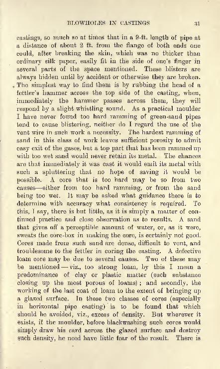
BLOWHOLES IN CASTINGS 31
castings, so much so at times that in a 9-ft. length of pipe at
a distance of about 2 ft. from the flange of both ends one
could, after breaking the skin, which was no thicker than
ordinary silk paper, easily fit in the side of one's finger in
several parts of the space mentioned. These blisters are
always hidden until by accident or otherwise they are broken.
The simplest way to find them is by rubbing the head of a
fettler's hammer across the top side of the casting, when,
immediately the hammer passes across them, they will
respond by a slight whistling sound. As a practical moulder
I have never found too hard ramming of green-sand pipes
tend to cause blistering, neither do I regard the use of the
vent wire in such work a necessity. The hardest ramming of
sand in this class of work leaves sufficient porosity to admit
easy exit of the gases, but a top part that has been rammed upwith too wet sand would never retain its metal. The chances
are that immediately it was cast it would emit its metal with
such a spluttering that no hope of saving it would be
possible. A core that is too hard may be so from two
causes either from too hard ramming, or from the sand
being too wet. It may be asked what guidance there is to
determine with accuracy what consistency is required. To
this, I say, there is but little, as it is simply a matter of con-
tinued practice and close observation as to results. A sand
that gives off a perceptible amount of water, or, as it were,
sweats the core-box in making the core, is certainly not good.
Cores made from such sand are dense, difficult to vent, and
troublesome to the fettler in coring the casting. A defective
loam core may be due to several causes. Two of these maybe mentioned viz., too strong loam, by this I mean a
predominance of clay or plastic matter (such substance
closing up the most porous of loams) ;and secondly, the
working of the last coat of loam to the extent of bringing upa glazed surface. In these two classes of cores (especially
in horizontal pipe casting) is to be found that which
should be avoided, viz., excess of density. But wherever it
exists, if the moulder, before blackwashing such cores would
simply draw his card across the glazed surface and destroysuch density, he need have little fear of the result. There is

32 FACTS ON GENERAL FOUNDRY PRACTICE
no necessity for carding the whole core ;as the roughing
of the top side will ensure a free exit of the gases contained
in the core. To those who may have doubts upon this matter
I should like to draw their attention to the contrast of a dry-sand and loam core as against a green-sand one. In using a
green-sand core, should the core" scab
"the unanimous opinion
would be that too hard ramming was the cause. This is
somewhat similar to what takes place with a dry-sand or loam
core that is too hard and glazed on the surface, with this
difference that we get the blister on the latter, while wehave the scab on the former, the blister being due to the
fact that the surface of the core has remained intact through-out the period of fluidity, and thus has prevented the escapeof gases. But were the surface of the core to break away(a thing that has never happened in my experience) there
would be a scab in the place of a"blister," thus clearly
showing that blisters or blowholes in such castings are caused
by laxity in venting.
BURNING OF CASTINGS
The process of "burning" means the renewal of a defective
part of a casting by pouring fluid metal on to it until the
defective part has become fluid, and then filling up the spacewith fluid metal. Or, the ends of two separate pieces may be
joined together by pouring metal right down through anybroken casting, as shown in Figs. 19 and 20, and thus unitingthe two ends into one. Care must be taken to give plenty of
metal for chipping, turning or finishing. If this be attended
to as directed, and the burned part be finished an inch or
two outside the new metal, it will be almost impossible to
detect where the joining of the old and new metal begins."Burning
"is not done well by quite a number who
attempt it, and doubtless this in a measure accounts
for the prejudice which many engineers have against it.
Many attempt to perform this operation without clearly
understanding its essentials. Thus no one can " burn " whodoes not take due account of the effects of the expansion and
contraction of metals. It is true that this is not a branch of

BUENING OF CASTINGS 33
the trade that is accessible to the ordinary moulder in thesense that other foundry practice is ; and it is to those whoare so unfortunately situated, and desire to know somethingof the subject, that this chapter will be of most value.
"Burning Cold." It is an easy matter if we simply look uponthe part to be burned as a hole in a casting, and a pouringof metal on such a part until it becomes fusible, and then the
filling up of the hole to our satisfaction with fluid metal. Butif nothing be done to expand this part of the casting pre-
viously to burning, and if it be of cylindrical section, thenthere is no chance whatever of such an attempt at burningbeing a success, in so far as its capabilities of withstanding a
static pressure test of any kind is concerned.
By the foregoing it is not to be inferred that to" burn "
without heating castings, in every case, to a dull red heat is
FIG. 19. FIG. 20.
an impossibility. All castings or parts of castings that may be
said to possess regular shrinkage, such as the one illustrated in
Fig. 19, are quite safe, and have no need of previous heating.In Figs. 19 and 20 it will be seen that in burning right down
through this broken shaft or bar, a certain amount of expansionmust take place. It will also be seen that there is nothing to
interrupt its expansion, and, since this is so, there is likewise no
restraint in its contraction. Had such an article been bound, as
the spokes of a wheel are bound to its boss and the rim, such
a method of burning, as shown here, would prove an absolute
failure.
Fig. 21 is another example of what can be done with
perfect safety without previously heating the casting, and if
such a flange be attached to a pipe, or any other cylindrical
casting, and the flange be broken not too near the fillet of the
body attached to the flange, there is no danger of the casting
cracking from expansion by the process of burning without
previous heating. It is better in such cases as this to makeF.P. D

34 FACTS ON GENERAL FOUNDRY PRACTICE
sure that the burn will all be of new metal, and sufficiently
far into the flange to admit of the bolt holes being drilled
entirely through the new metal, because, should it happen that
the drill in boring the holes in the flange came in contact
with the chilled metal whichFinished to Size
j ^Burned inevitably joins the old and the
new, the chances are that the
casting would run much risk of
being lost altogether throughthe drill not having the powerto get through the chilled metal
in question.
What is stated here as apply-
ing to the burning of"cold
castings," applies with safety to
any terminal or other parts
of a casting that are in every way free to expand and contract
without developing undue strains in any direction.
Having shown in a practical way those classes of castingswhich can be burned with safety without heating we will now
give one or two examples where heating previously to burningbecomes an absolute necessity.
Heating. In the first place take a casting with a cylindrical
body, which may either be cylinder, pipe, valve, plunger
barrel, or square hollow section of any kind, and with no
internal attachments cast on. Now, with any of these
castings having a defective part, there is no difficulty in
burning such castings to withstand as much pressure, if
not more, than the soundest part of the entire casting, providedit be gone about in a right way.The modus operaiuli should be as follows : Place the casting
on the dead level with the part intended to be " burned."
Secure the same by ramming properly with sand, or other-
wise. Next surround the casting or as much of it as may be
necessary, by a perforated brick wall, or improvised oven
sufficiently high to enable the top to be covered with plates
and so form a temporary furnace. Then, build a fire and
light it, and when the smoke has almost exhausted itself,
roof across with the plate or plates mentioned, and when

VENTING 35
the casting has reached a dull-red-heat apply the ladle with
its metal contents and " burn." Every operation, wherever
possible should begin and end with one ladle of metal, and
this is specially so when a crane ladle has to be resorted to.
On the burning being completed it should instantly be covered
over with charcoal or blacking. This secures it from atmo-
spheric chilling, and as a consequence the metal is softened,
thus making it easy for chipping and filing. With the" burn "
covered over with blacking the plates are again thrown over
this temporary furnace, and the whole affair is allowed to cool
as if it were an annealing oven. With such treatment as
above mentioned, no one need fear the result, as I have never
seen it fail to give the greatest satisfaction.
But whether heated or cold, castings are in no way weakened
by burning if in the process of burning they have been allowed
to expand and contract in the manner previously referred to.
Brass may be, and is, burned cold ;steel is similarly
treated; but in these cases the ductility or malleability of
these metals admits of"pinning," and so saves the castings
from becoming"wasters.'
5
Pinning thus with cast iron is
an impossibility because of its hard and unyielding nature.
VENTING
All moulders who desire to master the intricacies of their
trade should very carefully study the subject of venting. If
venting be done imperfectly, blowing, scabbing, or both
together are likely to occur, and that which should have been
a good casting turns out a scrap, and hence the importance of
venting properly and giving means of easy exit to the gases.
A slight digression may be made here on the question of the
finishing of a mould as it relates to venting, and what is said
at present specially applies to heavy green-sand work. The
principle, however, might with advantage be applied to all
branches of moulding. The fault common to jobbing moulders
in finishing is the desire to polish the surface until the grainof the sand which composes the mould becomes almost
imperceptible. Wherever such unnecessary work is performedthe danger of scabbing is greatly increased, even although the
D 2

36 FACTS ON GENERAL FOUNDRY PRACTICE
vent wire may have been applied with intelligence. The reason
of this to practical men is obvious, as such glossy polishing
destroys to a great extent the porosity of the surface, and
the metal in consequence cannot come to rest in contact with
the surface of the mould, until the polished face breaks awayto allow the escape of steam and other gases, thus causing a
scab on the casting. Therefore it will be observed that dis-
criminate venting, form and efficiency should be the guiding
principles in finishing a mould, leaving as much polishing as
is necessary to come after blackening or black-washing.
Fig. 22 will serve to show what is required in general
practice. In looking at the relative position of the vents,
viz., the bottom A, the top C, and the sides B, I believe it
is within the mark to
say that the dangerof scabbing on the
bottom is three times
greater than it is
likely to be on the
sides, and the dangerfrom scabbing on the
top side is almost nil.
In the foregoing I
have merely shown
effect; but what of the cause? The only reason I can assign
for it is the natural tendency which gas has to rise upwards,and were it not for the vents that are seen on the bottom of
the mould (Fig. 22), nothing could prevent such a mouldfrom producing a badly scabbed casting.
Having made the principle of venting the bottom presumablyclear, it leaves one but little to say concerning the side vents.
It will be noticed that these conduct the gases through the
joint of the mould, but should they fail to make their escapeas mentioned, there is no reason to doubt that were the side
vents connected to the coke bed, as shown in Fig. 22, the safety
from scabbing in such a job is equally secured. There is no
fixed rule that all vents should pass straight upwards in the
vertical position, the very opposite is the case in many jobs,
as, wherever the coke bed is necessary in the venting of the
Vents
FIG. 22.

VENTING 37
mould, all gases must pass downwards into the coke bed before
making their way through the tube D, as shown on the figure.
Still, as a principle, let them off as quickly and freely as
possible.
In the top part E, I have already stated that the danger from
scabbing is almost nil. This is attributable to the fact that the
gases make their exit without coming into touch with the
metal. It will require no great stretch of imagination to see
that when the mould is filled up to the top with metal, the
gases in the top-part pass off quite uninterruptedly. This is
entirely the opposite of what takes place at the bottom, as wefind these seeking to make their way through the surface of
the mould, and but for good and direct venting to the coke
bed, as seen at Fig. 22, and a speedy covering of the surface
of the mould while casting, the gases would obtain the masterywith disastrous results.
It is a disputed point with many moulders as to whether
it is necessary to use the vent wire for the top part or not.
Practically, I have always discarded it, as I believe all
moulding sands are sufficiently porous to make such venting
unnecessary, and that metal will lie in contact with any flat
top-part of a mould, however hard rammed in green-sand, or
imperfectly dried in dry-sand. The only thing that can
happen with the latter is the extra tenacity with which the
sand clings to the casting, but it in no way seriously affects it.
This adhesion is caused through the generation of steam,
which more or less comes in contact with the casting the
moment the mould is filled. Again, I consider a top-part that
is not vented to be stronger on that account, and has less
tendency to be " drawn down," as the gases that generateat time of casting are better held, inasmuch as there are no
vents in the top whereby they would be able to escape more
readily. Thus it will be seen that with the greater pressureon the flat roof, the top-part is thereby carried up ; conse-
quently the danger from "drawing down" is greatlyminimised. But I must not be misunderstood concerning the
difference between flat top-parts, and those that have cores or
projections attached that have been rammed from pattern.Wherever there are projections, "pockets," or anything that is

38 FACTS ON GENERAL FOUNDRY PEACTICE
rammed up in a top-part and projects from the surface, such
must be vented and with the greatest care.
THE USE OF THE EISER IN CASTING
"Riser" is the name given to the overflow of metal in-
dicating when a mould is filled at the time of casting. Risers
are necessary for a three-fold purpose, first, as already stated,
to show when a mould is full; second, to relieve the highest
part of a mould of the dirty metal which invariably makes for
the highest part, and third, for feeding purposes. They maylikewise assist in checking the pressure and velocity of the
metal at the time of pouring two very important matters for
which a moulder must intelligently provide.In the first place, it is necessary in casting for one to have
an idea as to the most suitable moment for checking the
ladle. It is no uncommon mistake to see a mould undulystrained for want of precision in this matter.
The number of risers in a job should always be fixed and
proportioned as far as practicable in accordance with the size
of the pouring gates. Care should be taken to have the risers
at all times somewhat less in area than that of the pouring
gates, otherwise, the force of compression necessary for the
casting will be insufficient. If we consider a job being cast,
the risers of which have twice the area of the pouring gates,
and the metal is somewhat duller than desirable, the casting
is sure to suffer to some extent from want of compression.This is due to the metal having failed to rise in the riser
basins owing to the extra area of the risers, thus diminishingthe fluid pressure.
No doubt much work is cast without the aid of risers, but it
is mostly of an architectural order. Even in this class of work
some prefer what is called a " blow off" about the corners or
terminus of the mould, which is the means of brightening upwhat would otherwise be a dull part of the casting ;
but as
this may not be more than a twentieth of the pouring gate, it
is not necessary to treat it after the manner of a riser. This
class of work is always perferred with as little broken skin as
possible, and as it must be cast at a high temperature, risers
are not a great necessity. The principle of moulding here

THE USE OF THE RISER IN CASTING
If FIG. 23. u
adopted is what is known as the" turn over" with top and
bottom boxes. These being tightly clamped, with ordinary
care there is no real danger from straining,1 no matter at
what speed the mould may be filled.
The placing of a riser on the highest part, must at all times
be observed, even at the sacrifice of all other considerations.
It may be that proportionately to the thickness of metal, there
is no real necessity for placing a riser here for feeding
purposes ;but as this
is the highest part of
the casting, the riser
is indispensable, in
order to relieve the
dirt or kish which is
sure to locate itself
in this part. While
clearly showing the
necessity of the
risers on the highest
parts, it is likewise
necessary to place
risers on other parts
which may have
considerably thicker FlG 24.
metal, necessitating
feeding, as often occurs with certain castings or parts of
castings.
In Fig. 23, riser B, it will be seen that the flange is much
larger than that at A, at its opposite end. Of course this
flange is proportionately thicker, in consequence of which
this part of the casting is longest in setting; and with no
application of the feeder here, the only result possible would
be what is termed a " drawn hole," showing itself probably
to a considerable depth into the casting. This would be more
intensified were the riser of a small size say, one-third the
thickness of the flange. The riser B should be of an oblong
shape, its breadth being not more than a J in. or f in., less
than the full thickness of the flange. It must be obvious from
1
Except those parts in immediate contact with the pouring gates.

40 FACTS ON GENERAL FOUNDRY PRACTICE
this increased size that the riser gate remains fluid for a
longer period, which in its turn has the better chance of
feeding the flange, even though no rod be applied.While such a gate as the one described may be reckoned as
a factor of safety in securing a solid flange, it by no means
guarantees a solid casting, and entire satisfaction can only be
obtained by the use of such a gate and the action of the
feeding rod. In Fig. 23, basin A, the flange being consider-
ably less, there is no real necessity for applying the feeding rod
here, as many moulders do. We have used Fig. 24 as a contrast
to show the difference of a cylindrical body without flangesin its relation to risers and feeding. A casting of this typehas the same necessity for risers as the previous one, with this
difference that in Fig. 23, A may be said to serve a two-fold
purpose, that is, while relieving the mould of its dirtiest metal
(which invariably makes for the highest part of the mould), it
also serves the purpose of feeding; but as Fr*. 24 shows no
flanges, and there is nothing but proportionals ,:etal through-
out, feeding is not a necessity. But it is ap Uy necessarythat the gates at the extremities should be there, in order that
these parts of the casting may be as clean as it is possible to
get them. It will be seen from the figure under consideration
that the metal is striking right across the back of the core
and finding its way to the bottom ; it gradually rises right
to the spot where it first entered the mould, but on its return,
it had laden itself more or less with an accumulation of dirt,
and may be dull owing to oxidation. Hence the need for the
end risers.
Next we will take up the question of the open or shut riser
at time of casting. It is stated by those who seek to upholdthe open riser that the increased volume of air and gas under
pressure naturally seeks for a speedy exit, and if refused such,
the result can only be detrimental to the mould in causing
scabbing. Then, again, they maintain that by keeping the
risers open the dust caused by the motion of the gas finds an
easy way of escape, which is the means of securing a sound
and clean casting. This sounds all very well in theory, but it
is sometimes forgotten that with closed risers there is no current
of gases blowing off. No two moulds can be said to generate
THE USE OF THE BISER IN CASTING 41
gases alike, they at all times being dissimilarly placed throughvariation of temperature and dampness inherent to the sand
and atmosphere. Take as an example a dry-sand mould which
is comparatively free from gases ;it is of little consequence
whether its risers be open or shut. Should the gases be
blowing off with considerable force, there is no dread of any-
thing going wrong with the mould, the strength of which is
more than able to resist the strongest current of gases possible.
Then, again, the gases being almost nil compared with a green-sand mould, we have always been inclined to leave the risers
open, such being the means of allowing any steam to escapecaused by dampness created, it may be, through the stampingof
"bearings
"or daubing of joints with loam.
The treatment applicable to risers in dry-sand work is equally
good for loam. But to return to the most critical point,
namely, risers in heavy green-sand work, we would in everycase advise those who have to handle such to adhere rigidly to
closed risers.
We may now make a brief allusion to the advantages of
compressed gas sustaining a mould at the time of casting.
But before referring to this point it would be well to consider
from whence those gases come. In a green-sand mould the sand
may be said to contain about 20 per cent, of coal (for heavy
work) in the form of coal-dust, which is ground to the finest
possible condition; then the other ingredients in the black
sand, which forms a good part of the bulk of the facing sand,
contain in a moistened state what may be termed "marshy
matters," all of which combine to form the gases referred to.
A mould that is ready to receive metal can contain nothingbut air, but immediately molten metal enters such a mouldthe gas begins to generate, and is intensified in pressure until
the mould is finally filled, such gases being forced to maketheir exit through the interstices of the top part and the
surrounding vent holes which usually accompany green-sand
moulding. This is one of the primary advantages which are
to be obtained by the risers being closed. Again, if we consider
the interior of a mould, we shall see what advantages are to
be gained with such a mould under gas compression. Thefact of such gas under pressure seeking for an exit goes a

42 FACTS ON GENEEAL FOUNDEY PEACTICE
great way to sustain the whole interior, and no part of the
mould is more sustained than the top, this part being the
most liable to"drawing down "
through the heat of the
metal, and more especially is this so where the mould is too
long in filling. No such advantages as here referred to can be
got with the open risers, as the gases under such conditions
are supposed to pass freely through the risers as they generatein the mould, therefore we should continue to keep to the
closed riser, especially in green-sand moulding, knowing that
with such it is an impossibility to err in so far as the treat-
ment of risers is concerned.
CHAPLETS
Chaplets are a necessary evil that moulders will probablyhave to contend with so long as castings are made. One can
scarcely think of them being in a casting without doing moreor less harm, and although in hundreds of cases the evil never
shows itself, the weakness of those parts where chaplets are
embedded would be very apparent if the casting were broken
up. At the same time chaplets can be used, and when
intelligently applied do no serious harm to a casting either
under steam or water pressure. The indiscriminate use of
chaplets has been the means of losing many a good casting,
and the safest rule for moulders to go by is to add a little
more metal wherever it is necessary to employ a chaplet. If
this be carried out it will certainly give the greatest satisfaction
to all parties, since it is an admitted fact that chaplets cannot
be interspersed among the cores in order to keep them in their
places without weakening the metal.
It is scarcely permissible to place a chaplet on any partwhich may have to be polished, but in cases where it is
necessary to have one or more the only way to get over the
difficulty is by bedding the studs half an inch or so below the
surface of the mould. These projecting from the face of
the casting can be easily chipped off by the dresser or fettler at
the time of cleaning the casting, and wh^n machining takes
place the worst that can be noticed is a white spot on the
finished surface caused by the malleable iron being denser
than the cast iron which enshrouds it.

CHAPLETS 43
Many of the methods adopted in foundries to overcome the
tendency which chaplets have to create blowholes are quite
unsuitable, and the tarring process, as it is known to moulders,is perhaps the worst. I have worked in shops where it was
the only remedy in use. Now, if I were asked what would be
the best thing to do to admit of a mandrel being easily taken
from a casting, I should unhesitatingly say tar it. The only
way to get a casting with a tarred chaplet steam or watertight is
by casting at a temperature higher than is good for the mould
generally. This high casting temperature enables the metal
to destroy part of the coating of tar before settling down. The
application of chalk also cannot be recommended, although it
is regarded by some as having a beneficial effect in absorbingwater and preventing the formation of watery beads which con-
dense on the chaplets in every green-sand mould which is closed
for any length of time before casting. Again, many pass
chaplets through the fire, and this is not without good effect.
The dust, however, which adheres to the burnt chaplets after
this treatment is objectionable, and they should never be used
until they have been coated with oil. The oil promotes the
union between the metal and the chaplets by the reduction of
the oxide of iron on the surface of the latter.. Indeed, chaplets
that are comparatively clean are quite safe with oil alone.
Tinning of chaplets is commendable, and where this is
properly done it has its advantages over some of the cruder
treatments. As this adds considerably to the cost it frequently
happens that a compound of spelter and tin is substituted,
which has a detrimental effect, and cannot give the result
desired. Although tin has the greatest affinity for cast
iron, and in that way, I believe, has the greatest accep-
tance among moulders, still, this has not been found the
panacea for all ills that accompany the use of chaplets.
Wherever these are in use, moulders would do well to see,
first of all, that they have been dipped in pure tin, and not
galvanised as frequently happens ; also to make sure that the
dipping has been perfect and complete, as chaplets that
remain a long time in store become rusted on those parts that
have been imperfectly tinned. And a chaplet used in this
condition cannot do otherwise than disturb the metal, thus

44 FACTS ON GENERAL FOUNDRY PRACTICE
creating blowholes in contact with the rusty part referred to.
However, by dipping such a chaplet in creosote the oxide
of iron will be destroyed, and affinity with molten iron
secured.
To paint with red-lead is an old device, and so far is
serviceable with certain classes of castings ;but castings that
have to withstand hydraulic pressure certainly will not do
well with chaplets so treated, because, were one to rub or coat
a chaplet with dry red-lead putty it will be obvious that no
adhesion could take place between metal and chaplet. Hence,the only hope is in the red-lead as a paint, and, through the
oil in the paint, combustion takes place as the metal surrounds
the chaplet, resulting in a fair amount of success generally.
And now for the last of those antidotes, which is the best,
cheapest, and most commendable of all, viz., creosote. It
does not matter how rusty a chaplet may be, this liquid is
at all times capable of making it fit for use. The truth of this
assertion may be demonstrated in the following way : Take
a piece of rod iron, no matter how rusty, dip it thoroughly in
creosote, and then put it into a ladle of molten iron, and that
which otherwise would have created an explosion, is received
by the iron with comparative placidity. As this mode of
treatment costs so little in time and money, chaplets, although
tinned, are safer when given a coating of creosote.
SHRINKAGE
There is perhaps no property of metals which gives more
trouble to the founder than that of shrinkage, and intelligent
observation and careful thought are needed if he is to deal
successfully with the daily occurring problems connected
with it.
The loses amongst our engineering craftsmen and others
due to lack of knowledge of the effects of expansion and con-
traction have been at times demonstrated to us in practice.
For instance, take the case of a double beat valve, whose
different parts are cast of different metals such as gunmetaland iron, which when exposed to the same heat while working
gives very unsatisfactory results due to want of uniformity of

SHRINKAGE 45
expansion of the different metals of which the parts of the
valve are cast. Under such conditions of heat the valve face
becomes faulty, and cannot act with the precision which goes to
make a good valve. Consequently all constructions that are
exposed to heat must, as far as possible, be cast of the samemetal so that there may be uniformity of expansion and con-
traction of all the different parts. The importance of this noone can over-estimate in any form of constructional engineer-
ing, and the branch of engineering that does not necessitate
a knowledge of the laws of expansion and contraction, is not
known to the man of experience.
The term "shrinkage
"is used here in a general sense, and
includes all volume changes that occur in the metal from
the moment that mould is completely filled until the castinghas reached the ordinary temperature. It may be said with
safety that no iron with which the founder has to deal contracts
regularly as the temperature falls; indeed, in many cases
shrinkage may conveniently be considered as occurring in
two stages. The first stage covers the interval between the
filling of the mould and the complete solidification of the
metal, and is the cause of"draw," vacuum holes, and what
are often incorrectly called" blowholes." The second stage
occupies the period between the complete solidification of the
metal and the ordinary temperature, i.e., until shrinkage is
finished, and the metal reaches a state of what may be called11absolute shrinkage
"; during this stage the effects of shrink-
age at times are seen in warped and twisted castings. Theeffects of shrinkage are thus of two kinds which may be called
internal and external the former, such as draw and shrinkage
holes, occurring while the metal is in the fluid and plastic
states;and the latter, such as warping and twisting, which
take place chiefly after the metal has solidified.
The internal effects of shrinkage are often seen in spongy,
porous and weak parts of heavy castings. This effect is
intensified at junctions or attachments where the cooling is
less rapid than in other parts, but these unsound junctions
usually only reveal themselves under the hydraulic test. Designand proportioning of thickness are thus important factors since
properly proportioned thickness gives uniformity of shrinkage

46 FACTS ON GENEEAL FOUNDRY PEACTICE
and uniformity of shrinkage gives elasticity and strength.
Those whose duty it is to design should see that they avoid
objectionable angles when designing for the foundry, because
what might prove a first-class design for constructional work,
would as likely as not mean irretrievable loss in the foundry
through irregularity of shrinkage.We now pass on to the consideration of the shrinkage of
metal causing warping or twisting, due to unequal cooling.
In this phase of shrinkage it is not so much a case of unequaldistribution of metal, as a question of conditions relative to
the position of casting. Certain articles have a tendency to
twist in cooling, but if turned upside down in casting the
result would be quite different. For example, take a casting
of U section and of equal metal, and first cast this jobwith the bottom down. The bottom side of this casting
will then inevitably remain hot considerably longer than
the sides, and the result is always found to be that both
ends will incline downwards and thus concave the casting.
Next mould a second one from the same pattern, but this time
with the bottom upwards, so that what was formerly the hottest
part of the casting, is now more exposed to the atmosphere,and consequently brings about a more uniform cooling, a result
much to be desired, but at times a practical impossibility.
There is no absolute rule that must be followed in this branch of
founding, as everything cast has its own peculiarities in cooling,
and nowhere do we find the trouble of warping more pro-
nounced than in the shrinkage and contraction of light and
hollow castings. It should be remembered that the central and
inside parts of castings cool less rapidly than the outside
and ends. Hence follows the concaving of castings of Usection when cast downwards, the extremities of the castings
being turned inwards under the influence of the unequal rate
of cooling. Therefore the camber in the bedding down in
this position of sole-plates and bearers of U section requiresto be deflected in the middle, so as to bring these castings
straight from the mould.
In this connection the responsibilities between foundry and
pattern shop are frequently disputed. Wherever this is the
case, it ought to lie with the founder to decide the question,

SHEINKAGE 47
unless the pattern shop assumes responsibility in those matters,
a thing not usually done.
Obviously, castings of the hollow type, whose averagethickness of metal may approximately be put at J- in., do not
lend themselves to the troubles of shinkage attending the
production of thicker metal castings. And as a matter of
fact, if there be a plastic condition in light work, with castings
that are newly poured, it must only be of momentaryduration. Consequently no irregularities of shrinkage causing"draw," as are common with heavy sectional metal, can
possibly take place. However, those engaged in hollow work,
may think they have plenty to contend with in"warping,'' a
trouble due to shrinkage which is scarcely known to some
heavy metal workers.
The habit that some light metal moulders have of"baring
off"castings at certain parts to secure uniformity of cooling
is not, in the writer's opinion, good practice. All such opera-
tions, however carefully performed, must deteriorate the casting
by "shortening," or unduly hardening the grain of the metal,
which at best, can do no more good for the purpose intended,
than is to be got from the more rational method of camber.
It is well known that the internal structure of all metals,
whether cast or forged, is influenced by the rate of cooling.Hence it comes about that the casting that is allowed to cool,
closed up and undisturbed in the moulding box in which it
has been cast, proves to be a casting of the softest texture of
metal possible and a superior casting for all concerned. Thebest and most experienced moulders know that conditions
such as unequal exposure to wind and weather, gates for
running and rising and where to place them, position of
casting, inequality in the dampness of the sand, and perhapstwo castings in one box instead of one, are all factors to be
reckoned with in securing straight castings from the sand.
These are not trifles, since, for example, in lengthy castings,where two are cast side by side in one box, a twist sideways is
sure to follow. This is due to the fact that the two insides of
the castings are longer in cooling than their outsides.
Design. The casting illustrated in Fig. 25 has four equalsides. Its diagonal bar in foundry designing is exceedingly

48 FACTS ON GENEEAL FOUNDRY PRACTICE
bad, and wherever employed gives evidence of limited know-
ledge concerning the effects of shrinkage in castings. Diagonalbars, however serviceable in structural work, are at all times
mischievous to a greater or less extent in castings. Fig. 25
shows in its worst form the results of unequal shrinkage, andthe casting would be found to be warped or unduly strained, if
not actually broken.
Fig. 26 may be looked upon as a better way of strengtheninga casting, and experience has proved that results are more
satisfactory than with the design shown at Fig. 25, but while
admitting Fig. 26 to be superior, both are objectionable,the only difference being, that in Fig. 26 the strain is better
FIG. 25.J
FIG. 26.
balanced on account of the opposing action of shrinkage throughthe additional diagonal bar, which brings the strain from the
four corners to the centre alike. Again, although Fig. 26 has
an improved balance of strain, still, with a casting so designedthere cannot be absolute equality of shrinkage ;
but another
way that such can be improved is by plating the entire
surface over with proportionate metal. This plating of the
surface tends to give uniformity of shinkage, although not
absolutely so, as the centre has the last of the pull in
shrinking. Diagonal design from corner to centre is not advis-
able ; therefore, wherever diagonal bars are designed, their
elasticity is improved by quarter circles as shown at Fig. 27.
This is a capital design for tank plates, and is better when not
more than J in. to 1J ins. in depth for the plate mentioned. A

SHRINKAGE
plate thus designed is much improved in elasticity, a factor of
considerable importance when designing cast iron. It not
infrequently happens that the projections or ribs, as shown,so add to the strength of the casting as to make it not inferior
to a plain plate double the thickness. Thus with a plate
J in. thick strengthened with the projections referred to, there
will be greater spring or resistance than is possible with a
plain plate 1J ins. thick.
In the case of the design shown in Fig. 25, some may saythat the diagonal bar, although it has a greater length to travel
in shrinking, will do so proportionately, and that all in the end
will shrink and finish as one. In theory this may be true,
but in practice I have never found it so, and in this particular
FIG. 27. FIG. 28.
case I can attribute this variation of shrinkage to nothing but
the variation of cooling. It will be obvious that the four sides
must cool first, and the diagonal bar, being enshrouded with
the heat from the outside part of the casting, must of necessity
shrink in the wake of the sides, thus causing warping, undue
straining, or fracture of a casting of the type of Figs. 25 and 26.
The great question in designing for the foundry is to see
that in doing so all parts, as far as it is practicable, shall
shrink together. Therefore, to rib after the fashion of con-
structional work is a great mistake, and anything so treated
with the design of Figs. 25 and 26, cannot, in the opinion of
the writer, have equality of shrinkage.Metals from 1 in. to 4 ins. in thickness, of design shown in
Fig. 28, I never saw fail, but experience has proved other
F. . i;

50 FACTS ON GENERAL FOUNDRY FRACTION
designs to be failures, and in some cases failure did not take
place until the castings had left the foundry, and as mightbe expected resulted in serious loss to all concerned.
Equality of Metal. Although not always possible, equality
of metal is much to be desired, and the greater equality
the less undue strain will follow the shrinkage of all metals
cast.
Many cases could be cited in support of this, but the most
common is that of the ordinary belt pulley with its necessarily
heavy boss. Every practical moulder knows that it would be
useless to expect these castings to keep from springing or
snapping, unless they be either split in the boss or other
means adopted to expedite the cooling of the boss, so that rim
and boss may cool together.
The method usually adopted in facilitating the cooling of
the boss is to fettle out the core and apply cold water with
discretion. Some engineers have an aversion to the use of
water here. They maintain that cold water hardens the boss,
thus making it objectionable for tooling. I agree that unless
the water be applied intelligently it will work mischief.
However, no one need be afraid of harm being done if theytake care while applying the water to see that the boss returns
to a greater heat in the bore than it possessed when receiving
the last application of water. Another way to cool these
castings evenly is to take off the cope and dig a gutter round
the rim, and fill this with hot metal in order that the rim
may retain its heat for a greater length of time, the object
of this being to cool rim and centre uniformly and thus prevent
the casting from springing in the arms or rim. This method
of treatment is hardly, perhaps, the ordinary way of doing
things, but it illustrates the kind of device moulders sometimes
have to employ in order to secure good castings from what
of necessity are badly designed patterns so far as shrinkageis concerned.
As another example take the spur-wheel type of castings
which are fairly proportioned in every part, the boss metal
being determined by the thickness of metal at the pitch line
of the teeth. Yet, when we consider the relatively larger
amount of heat in the heavier metal of the centre, and that

SHRINKAGE 51
arms and rim cool first, it is easy to understand that there
must be undue straining of some part or parts of the casting.
If no special treatment be given to such castings, the weak-
ness invariably locates itself about the centre of curve on the
spokes adjoining the rim, and this defect is always greater
with the cross section spoke, and is therefore not so observable
with the H spoke type of casting. Needless to say, the splitting
of the boss goes a long way in relieving the strain which would
otherwise be on the rim, the splitting being done by plates
or cores, the latter being preferable. I have never seen it
necessary, even in a 12-ft. diameter "spur wheel
"and, say,
7 tons weight, in cast iron to split in more places than between
two opposite arms ; but were anyone to attempt even a muchsmaller diameter in steel, such would more or less end in
failure, if split in only two places, through the casting
concaving itself out of truth, thus making it impossible to
gear with its pinion. Therefore, assuming a six-spokedwheel to be cut in two places Jor cast iron, it would take three
in steel to avoid concaving.
Camber and uniformity of cooling. To camber a pattern in
bedding down is to give it the necessary deflection, in order that
the casting made therefrom will come out of the sand without
being warped or twisted. Practical menare aware that there is no fixed rule to
guide them here; it is all a matter of
experience gained through jobs previously
passing through their hands, and even
then the moulder receives surprises, for
it does not always happen that two cast- FIG. 29.
ings, made from the same pattern and
by the same moulder shrink alike. The reasons for this are
various. First of all there are atmospheric conditions to
contend with. For an example, let us take a horizontal enginebed plate (Fig. 29), which may either be 20 ft. or 40 ft. longthe length does not matter, except that in the greater length the
danger of warping will be practically doubled. Now, supposeone end of the casting is in close touch with the door of the
foundry, and a strong wind blowing on this exposed partwhile the other end was in comparative warmth, it is evident
E 2

52 FACTS ON GENEEAL FOUNDRY PRACTICE
that the exposed end will cool much more rapidly than the
rest of the casting.
Further, if we reckon the camber of in. on a 20-ft. length,of Fig. 29, that is, f in. deflection in the centre, any alteration
of the metal, as shown at AA in Fig. 29, would have to he
reckoned with ; that is to say, were we to add to the depthof the metal on the base AA we retard the cooling of this partof the casting, and with one-third more metal, the chances
would be that no deflection at bedding down this job wouldbe necessary. But on the other hand, if the metal was reduced
on the same parts by the same proportion, producing an
opposite effect, then the camber in such
a case would require a proportional in-
crease.
The foregoing is only applicable to
those sections of Figs. 29 and 30,
when cast in the position as shown
FIG. 30. here. The gates and risers should
also be attended to so that these
may be relieved from all possible gripping on the bars of
the cope or box with which the casting is covered. And,should a casting require more than two separate flasks, it is
necessary to remove all but the two end ones during cooling
and before shrinkage is complete.
Fig. 80, although of a similar design to Fig. 29, is heavier
metal along the base, besides being" boxed." If in bedding-
down the pattern for such a casting one were to camber by
deflecting the middle, as referred to, this would be exactly
the opposite to what would be required to make a straight
casting, because the heavier metal on the top side of
Fig. 30 makes this part the last to cool, and hence the last
to shrink.
So far we have only considered uniform design with the
usual attachments for binding bolts, cylinder feet and pillow
block faces ; and wherever there is nothing more than these
to contend with, the difficulty of making straight castings is
not extraordinary. But the tendency in these days is to
design regardless of the consequences attending shrinkage.It has now become quite common to cast on to the sides of

SHRINKAGE 53
castings projections of various forms which hitherto were
jointed and fitted, thus intensifying the danger of twisting or
warping while cooling.
In short, we have complications of design and varieties of
thickness in one casting, ostensibly for the purpose of reduc-
ing machining and fitting, with a view to producing the
greatest economy possible. This may be so far correct for
the departments referred to; nevertheless, these attachments
or complications have made moulding more than ever an art,
and have given demand for a degree of skill and ingenuity
hitherto unknown in the trade.
But wherever these heavy projections occur, and are likely
to be considerably longer in cooling than the rest of the cast-
ing, dig round with discretion and expose these parts, and so
bring about uniformity of cooling as far as possible.1
Indeed,
there is no absolute uniformity of cooling, and the nearest we
can get to this is in a straight bar, or plain plate or frame,
and even the centres of the former inevitably keep warmest
until shrinkage is completed. Moreover, a straight plate and
a straight bar are the only castings that I can think of that
are free from shrinkage strains, internal and external, a trouble
so common to castings poured with every kind of metal.
But although founders should be competent to overcome
all difficulties caused by abnormal design or attachments, they
ought to let those responsible understand that these difficulties
and complications involve much risk to the founder ; a good
understanding between the drawing office and the foundrywill reduce the risk of loss from this cause to a minimum.
Shrinkage by Premature Exposure. We shall but briefly
refer to this part of the subject, although its importance is
great; and we may be pardoned by what has previouslybeen stated, if we confine ourselves for the present to castings
which may have been lifted from the sand too soon or too
late. With many castings, that are prematurely exposedto the atmosphere, external shrinkage must considerably
1 In cases where, through unusual inequalities of thickness or design of
soleplates, such means do not give sufficiently uniform, cooling it is better
to "split" in some convenient part rather than have castings unduly-strained by unequal shrinkage.

54 FACTS ON GENERAL FOUNDRY PRACTISE
develop before internal shrinkage has properly begun, and is
aggravated when valve-seats and other internal adjuncts in
effect consign a casting thus treated to a short life, if nothingworse happens, through such unguarded treatment.
Castings that are to be polished, but otherwise plain, even
when cast with iron above the average density and price, if
left too long in the sand bring about a change in the
condition of the carbon, and instead of getting a polished
casting with a fairly good lustre, we get a dirty speckled
article, an eyesore to the founder and a short-lived article
to the buyer, that is to say, if it belongs to the anti-frictional
grade of castings. Thus a poor and cheap brand may be
improved by careful treatment, and a superior and costly one
spoiled by carelessness, want of intelligence, or perhaps both.
Although we have thus specifically stated the dangers
attending premature lifting of castings, and also, on the
other hand, shown its advantages in certain cases, it is
not to be inferred that all castings are injured by pre-
mature lifting. There is an old saying which says," One
man's meat may prove another man's poison ;
"so in like
manner, one casting's imperative treatment, if applied to
others, would in many cases scrap the castings. Thus it is
that castings of equal thickness and absolutely free from
irregular shrinkage, are perfectly safe when lifted somewhat
prematurely. Straight pipes, railway chairs, and such like
castings are free to be dealt with in the matter of lifting themfrom the sand, after being cast, as circumstances best permit.
Consequently, the subject of heat treatment, or the temper-
ing of castings, although absolutely essential for some work,is unimportant to other castings in the trade.
Slackening. Castings that are gripped at both ends, such
as is the case with long columns in dry-sand, have no need to
be slackened at both ends, as slackening at one end will suffice.
It is true that the pull in such cases of shrinkage will all be
from and towards the one end. But with things in normal
condition for shrinking, no harm can befall a casting thus
treated, while the unnecessary trouble of slackening at both
ends is saved.
It need hardly be said that the need for slackening castings

SHRINKAGE 55
is almost, if not altogether, confined to dry-sand and loam
work in the form of moulds and cores. And if many castings
moulded in green-sand were made in dry-sand or loam the
need for slackening would be imperative.
Those who handle loam work should know what will be the
total amount of shrinkage on parts requiring "slackening,"because the rigidness of loam moulds and cores compels the
relieving at times of some parts to assist the casting to
contract. And for this reason the interspersion of loam
bricks is frequently resorted to;but I do not favour such a
system or method in the building of vertical cores, since this
must at all times be a source of weakness. By far the better
way is to distribute the equivalent of the loam brick space
throughout the joints of the bricks in each course of the
structure, and by doing so we get no less flexible material as
a whole, and a positive guarantee against weakness, which
accompanies the interspersion of loam bricks as above
mentioned.
Loam moulders would do well to consider this division of
the subject, on account of the rigidness of the materials with
which their work is moulded ;and where projections, or such-
like, on castings have to travel by shrinking, they ought to
see that loam brick be placed next to the metal. Also, a
packing of ashes between the joints of hard brick will verymuch facilitate the ease and safety of shrinkage.
In studying Fig. 32, which is supposed to represent a
cylindrical casting 6 ft. in diameter, with bracket attached,
it may be asked, When should slackening begin ? The earliest
possible time is generally late enough, and with the job in
question cherry-red heat would be some time past before the
work of slackening could begin. Of course, it may be said
by many that slackening is not necessary. Moreover, I have
even come across men who maintained that they had seen as
much evil resulting from slackening as any good they ever
saw it do. I cannot agree with this, as my experience is all
in the other direction. The one point to know is what to
slacken and what to leave alone.
The barrel core in Figs. 31 and 32, or any other similar
core, wil! yield to the extent of f in. or f in. before

56 FACTS ON GENERAL FOUNDRY PRACTICE
shrinkage is complete. True, a great deal depends on the
intelligence of the moulder who builds the core, and if the
metal be 2 ins. thick the danger of such a casting crack-
ing through rigidity of core, although not slackened, mightnot be serious ;
but reduce the metal to 1 in., then slacken-
ing becomes an absolute necessity. In the 2-in. metal we
may assume that there is double the strength, and a con-
sequent elasticity, which gives it more power while skrinking
to crush, burn,, and destroy the vegetable and combustible
elements in the loam from which the core is made ;but with
1-in. metal we are quite safe in assuming that the half of this
destructive power is lost by the metal being closer grained,
and as a natural consequenceits elasticity is reduced also,
thus making it impossible to
withstand the necessary strain,
consequent on f-in. shrinkageon the core, as shown at
Fig. 81. Then, when the
metal's power to crush the core
ceases before its work is done
in shrinking and the limit of
elasticity of metal is gone, no-
thing can save the casting from
FIG. 31. snapping, if it be not slackened,
as shown at the arrow (Fig. 31).
This consists of the entire removal of a vertical strip of
brick from top to bottom of the core. Immediately after
this operation the top should be covered across and closed
up tightly so as to prevent cold air playing upon the partrelieved. This done, no ill can possibly attend the processof slackening.
Now, as to the vertical shrinkage of the job in question,and as shown at Fig. 32. Supposing this job to be about
12 ft. long, which would produce about 1J ins. of shrinkage,this means the top flange when shrunk must be nearer the
bottom than it was immediately after being cast. Suchan amount of shrinkage shows that everything likely to
interrupt its progress phould be slackened, otherwise results

SHEINKAGE 57
at best will be defective. At Fig. 32, and underneath the top
flange at A, is seen the amount of slackening required. If a
plain barrel with flanges at both ends, say, 12 ft. long, no
matter whether a loam brick is built underneath the top
flange or not, slackening as shown ought to be attended to.
But with a bracket E, as shown in same figure, slackening is
absolutely imperative. In doing so, come down stepwise from
the line of A, and get
underneath the bracket at
C; in this we fulfil the
double function of pre-
venting it from cracking
and, ensuring the metal
structure from being
racked, thus improvingwhat is naturally the weak-
est part of the casting.
Care should be taken to
see that the claw or flange
of the bracket D has full FIG. 32.
liberty to shrink, other-
wise the barrel may concave itself on this part of the bore
which would mean at least an extra"cut
"while "
boring,"should nothing worse happen.To sum up this question, it might fairly be put thus: All
which has been said, from a founder's point of view, resolves
on the one idea of uniformity of cooling, for if founders could
get this, together with no impediments in the process of
shrinkage, neither warping, concaving, convexing, .breakage,nor burst of any kind could happen.
PKESSUKE OF MOLTEN IRON (FERROSTATIC PRESSURE. 1
)
Moulders who are accustomed to work by rule of thumb
generally have hazy notions as to the influence of the pressureof the fluid metal in straining, bursting, or lifting the cope of
a mould. This haziness is probably the result of the failure
of some writers to apply their principles to the everydayi Ferrostatic Pressure
"is here suggested as a convenient term.

58 FACTS ON GENERAL FOUNDRY PRACTICE
wants of a foundry. It is only in the hope of clearing upsome of these difficulties that the writer has ventured to touch
upon the rudiments of this subject.
Pressure on the Bottom of a Mould. All liquids exert a
pressure on the bottom of the vessel in which they are placed,
and this downward pressure depends on the depth of liquid,
and also on the specific gravity of the liquid. It is quite inde-
pendent of the area of the bottom, that is, it does not matter
in the least whether the bottom is large or small, the pressure
per square inch is just the same. Since the liquids with which
we have to deal have large specific gravities, this downward
pressure is very considerable, and it is worth while to compareit with that produced by a corresponding quantity of water.
A column of water 1 in. square and 28 ins. high weighs about a
pound, and consequently if this column is placed in a vertical
position there is a pressure of 1 Ib. weight at the bottom;in
fact, any head of water 28 ins. in vertical height produces a
pressure of 1 Ib. weight per square inch at the bottom. Thus,
if a mould were filled to a depth of 28 ins. with water every
square inch of the bottom would be subjected to a pressure of
1 Ib. weight, no matter whether the sides are vertical or sloping
inwards or outwards ;if the depth were 56 ins. the pressure
per square inch would be 2 Ibs. weight, and so on. Now, sup-
pose this same mould is filled to the same depth (28 ins.) with
fluid iron, the specific gravity of which is, roughly, 7, i.e., fluid
iron is, bulk for bulk, 7 times as heavy as water. Eachcolumn of iron 1-in. square and 28 ins. high weighs 7 times
as much as the same quantity of water, i.e., it weighs 7 Ibs.,
and consequently there is a pressure of 7 Ibs. per square inch
on the bottom of the mould. If only filled to a depth of
4 ins. it would produce the same pressure as a depth of 28 ins.
of water. Thus, in casting a 20-ft. plunger not an unusual
length in these days there is a pressure at the bottom of the
mould, without taking into account depth of pouring basin, etc.,
equal to a head pressure of about 140 ft. of water, i.e., about
60 Ibs. weight per square inch.
Pressure on the Sides of a Mould. Every fluid exerts a
pressure on the sides of its containing vessel, and this
pressure gets gradually greater as we get further below the

PRESSURE OF MOLTEN IRON 59
surface. Thus, the side pressure at a depth of 2 ft. is twice
that at 1 ft. below the surface. In the case of a mould
filled with fluid iron the side pressure at a depth of 4 ins. would
be 1 ib. weight per square inch;at 8 ins., 2 Ibs. weight, and so
on. These figures refer to vertical depths below the surface,
and not to actual distances along the sides, if these are sloping.
Pressure on Floating and Submerged Bodies. Let us nowconsider the case of a solid body completely submerged in a
fluid. Here the fluid exerts a pressure on every part of the
surface of the body, top, bottom, and sides ; and the result of
this is that in every case there is an upward pressure tryingto push the body out of the fluid. By actual experiment it is
found that this pressure depends only on the size of the bodyand the specific gravity of the fluid, the actual value of the
pressure being equal to the weight of the fluid displaced bythe submerged body. Consequently, if this body has a smaller
specific gravity than that of the fluid i.e., it is, bulk for bulk,
lighter this upward pressure is greater than the weight of the
body and so the body is pushed upwards until it floats. Theactual force moving it is the difference between this upward
pressure and the weight of the body ; this moving force
may be called the lifting power. When the body floats it
does so in such a way that it displaces a weight of fluid just
equal to its own weight hence the lifting power has become
nothing. If the body and the fluid have the same specific
gravity, the weight of the body and this upward pressure are
exactly equal, and consequently the body will stay in anyposition in which it happens to be so long as it is completely
submerged. If, again, the body has a greater specific gravitythan the fluid, its weight pulling it down is greater than the
upward pressure, and so the body sinks. In all cases this
upward pressure is the same, no matter whether the body is a
long way below the surface of the fluid or whether it is only
just submerged, since the amount of fluid displaced is alwaysthe same.
As illustrations of these points, suppose a cube of wood of
1-ft. edge is submerged in water. The weight of the wood is
probably about 45 Ibs., while the weight of water it would
displace when submerged is 63 Ibs. Consequently, there is a

60 FACTS ON GENEKAL'FOUNDKY PEACTICE
force lifting it upwards of 18 Ibs. weight, and in order to keepthe wood underneath the water it must be pushed down with
this force of 18 Ibs. weight.
Again, 4 cub. ins. of iron weigh about 1 Ib.; when submerged
in water it displaces 4 cub. ins. of water, and this only weighs
^ Ib. ; consequently the iron sinks, its apparent weight being
now f Ib. Now let us consider the case we have to deal with
in core making. The specific gravity of sand is about
If, that is, it is .roughly one-fourth that of iron, and hence
sand floats in fluid iron just as wood floats in water, since
the weight of the sand is only one-fourth that of the iron
it displaces. Thus, if the sand core weighs 10 Ibs. the iron
Parting-Line
116
FIG. 33.
displaced weighs 40 Ibs., and hence an additional pressure of
30 Ibs. weight must be put on the core.
Pressure due to Fluid Metal in Gate. As soon as the level
of the fluid metal in the gate is above the parting line
(v. Fig. 33) this additional head of fluid causes an
additional pressure on all parts of the mould not only on the
bottom and sides, but also on the top. Suppose this head of
fluid is 8 ins. (depth of cope is 4 ins.), this additional pressureis 2 Ibs. weight per square inch, no matter what the size of the
gate may be i.e., both side and bottom pressures are increased
by 2 Ibs. weight per square inch. The pressure at the topis borne by the cope, and consequently this must be sufficiently
weighted to withstand a pressure of 2 Ibs. weight per square

PRESSURE OF MOLTEN IRON
inch. 1 This lifting pressure on the cope is confusing to
many moulders, who do not distinguish it from the lifting
pressure due to sand cores when submerged in fluid iron. In
the latter case the pressure depends only on the volume of
the sand core, and not on the area in contact with the cope,
whereas the pressure on the cope due to the metal in the
gate depends on the area of the surface of fluid metal in
contact with it.
Again, suppose the mould in Fig. 34 is 12 ins. square and
1 in. deep, the cope of the mould has an area of 144 sq. ins.,
and so the total lifting pressure due to the fluid metal in
the gate will be 288 Ibs. weight (i.e., 2 Ibs. per square inch).
If this same mould were placed on end, the area of the copein contact with metal would only be 12 sq. ins., and so the
total pressure to be borne by the copewould only be 24 Ibs. weight, though in
each case the weight of the casting is
the same. In this connection it maybe emphasised that it is very necessaryto distinguish between total lifting
pressure and pressure per square inch.
To illustrate further some of these
points it may be of advantage to calcu-
late the pressures experienced by the different parts of a
mould in a few special cases.
1. A solid cube, i.e., a mould 1 ft. square and 1 ft. deep
completely filled with molten iron (v. Fig. 34).
Pressure on bottom per sq. in. = 3 Ibs. weight.Total pressure on bottom = 3 X 144 == 432 Ibs.
weight.
Pressure on each side is nothing at the top, but
gradually increases to 3 Ibs. at the bottom.
Average pressure on each side, per square inch =1| Ibs. weight. Total pressure on each side = 1JX 144 = 216 Ibs. weight.
1 It must be borne in mind that the above calculations are only
approximate; also all copes must be weighted according to risks from
velocity or other contingencies of pressure or strain during the process of
pouring metal into moulds.
FIG. 34.

#TOfiWft**Vti
^i^S|
62 FACTS ON GENERAL FOUNDRY PRACTICE
2. A mould 12 ins. deep X 12 ins. square with core
10 ins. X 10 ins. X 12 ins. deep in centre, plan of
which is shown at Fig. 35.
Pressure on bottom per square inch (due to 12 ins.
head) = 3 lbs. weight.Total pressure on bottom = 44 X 3
= 132 lbs. weight.
Average pressure, on each side, per
square inch = 1J lbs.
Total pressure on each side = Ij X144 = 216 lbs. weight.
3. A mould 14 ins. X 14 ins. X14 ins. deep contains a sand core
12 ins. X 12 ins. X 12 ins., the
level of fluid metal in gate being 8 ins. above
the parting line (Fig. 33).
Area of bottom = 14 ins. X 14 ins. = 196 sq. iris.
Effective head of fluid iron = 14 ins. + 8 ins. =22 ins.
22.*. Pressure per square inch = -r- = 5'5 lbs. weight.
.-. Total pressure on bottom = 5'5 X 196 = 1,078 lbs.
weight.
Area of each side = 14 ins. X 14 ins. = 196
sq. ins.
14Average head of fluid iron = + 8 = 15 ins.
/. Average pressure per square inch = = 3'75 lbs.
weight.
/. Total pressure on each side = 196 X 3*75 =735 lbs. weight.
Volume of sand core = 12 ins. X 12 ins. X 12 ins. =1,728 cub. ins.
1728.*. Fluid iron displaced = ^
= 432 lbs.
Suppose the sand core to weigh 108 lbs., then the
lifting pressure to be resisted by the chaplets =432 - 108 = 324 lbs. weight.

FEEDING OR THE COMPRESSION OP METALS 63
Area of metal surface in contact with cope = 14 ins.
X 14 ins. = 196 sq. ins.
QPressure due to fluid metal in gate = j = 2 Ibs.
.'. Total pressure on cope, due to pressure of fluid
metal in gate = 2 X 196 = 392 Ibs., but to this
must be added the lifting pressure due to core
which may be transmitted to cope by chaplets,
i.e., 324 Ibs.
Therefore the total lifting pressure will be 392 + 324= 716 Ibs.
FEEDING OR THE COMPRESSION OF METALS
Perhaps no branch of foundry practice has given rise
to more controversy, or to which more attention has been
paid in trade journals than that of feeding, and it is
proposed in this chapter to put into concrete form what has
occurred to the writer in practice with regard to the feedingof castings.
To ensure success a founder must know how to mix and
adapt the different brands of iron to the various requirementsof the castings he intends to make, and what is the mostsuitable pouring temperature ;
but the question of the after-
treatment of castings by feeding is probably of still greater
importance ; he must know what castings should be fed, andhow this feeding should be done. The subject of the feeding of
castings is intimately connected with that of shrinkage, since
it is the shrinkage of metals during solidification that necessi-
tates feeding. There are, broadly speaking, three stages or
transitions in the cooling of metals from the molten state,
viz., (1) the liquid stage ; (2) the solidifying stage, duringwhich the metal is in a more or less plastic or viscous
state;and (3) the solid stage ; and it is while the metal is
in the liquid, and the second or plastic stages, that feedingmust be done.
The subject of feeding resolves itself into the following
problems : (1) Is feeding a necessity? (2) What class of
castings should be fed ? (3) How is feeding to be done ?

64 FACTS ON GENEEAL FOUNDEY PEACTICE
(1) In answer to the first of those questions we are safe
enough in saying that all castings, with but few exceptions, are
fed to a greater or less extent in some way or other, and the
only exceptions are those of extremely light metal, where
immediate solidification takes place with uniform internal
shrinkage. But, taking castings outside this range, the
conditions are altogether changed.A mould that is cast, and whose metal does not all solidify
immediately such as is the case with varied sections, never-
theless forms its outside shell, so to speak, throughout, but
specially at its extremities, while the still fluid interior" draws
"from the basins (where no "
emitting," as referred
to later on, takes place) during solidification. This first
formation of solid metal and plastic interior are importantfactors in the feeding of a casting.
It is true there never can be a fixed rule for feeding, as every
casting brings its own peculiar wants with it, and so does
every metal with which a mould is cast. But while allowingfor these conditions, it must be borne in mind that feeding is
a necessity, and whether we recognise this principle or not,
castings are in a measure fed automatically, and not in-
frequently unknown to the moulder from the source above
mentioned.
(2) What should be fed ? This question may be a little
ambiguous, since it has been laid down as a principle that
feeding is a necessity in the solidification of metals. This
admitted, it goes without saying that there can be but few
exceptions ; one of those exceptions having already been
referred to need not be mentioned again, and the only other
that I have ever experienced are those castings in which the
emitting or vomiting of fluid metal from the mould takes place
due to the expansion of malleable spokes, or it may be an
occasional core expansion, such as in the case of barrel-jacketed
and Corliss cylinder moulds, with their complex group of cores
so much enshrouded in metal.
As an example of malleable spoke expansion, let us turn
our attention to the casting of what may be termed the
bicycle-spoked pit-head pulley, or wheels similarly spoked.
It is known to those with experience in this class of

FEEDING OE THE COMPBESSION OF METALS 65
work that immediately on casting the bosses of these
castings a swelling action appears in the basins, and not
infrequently a vomiting follows, and for anyone to put the
feeder through the riser while such is going on would only
aggravate the situation, with the chances of losing the pulley
entirely. The substitute for a feeder here is a bucket with
water, the contents of which are judiciously applied to the
basins, so that a crust may be formed on the top, this crust
to be used for the controlling of the emission of the metal
from the mould. This is an operation that cannot go under
the name of feeding, although it is at times erroneouslytermed so. The stratagem employed for solidifying these
bosses is outside the province of feeding and need not be
further referred to at present.
To return to the question of what class of castings should
be fed, it looks a little elementary to say that wheel bosses of
every description should be fed. The treatment of these cast-
ings but trace the surface of the question, and is known to the
juniors of the craft. It is among the cores and at the fillets
of attachments and projections of castings that moulders must
search for the mischievous parts that are so vital to hydrauli-
cally-tested castings, and thereby gain the mastery in the detail
of feeding.
As already mentioned, one cannot know too much regardingthe importance of design, a thing, I am sorry to admit, few
moulders trouble themselves about. Were this better under-
stood by engineers and moulders alike, much of the work that
is scrapped would otherwise be good castings. It is true the
feeder cannot be got to reach all parts requiring its assistance ;
but other means can be applied, and, when judiciously
administered, have the desired effect.
Again, let us view what comes directly under the eye of the
moulder, and suppose we take a length of pipe, as shown at
Fig. 36, of course flanged at both ends, the flange B, whosemetal is proportionately thicker than A, is the last part to
solidify. This being so, the whole casting, as it is settling
down, must "draw" from flange B, so favourably situated byits extra height and increased fluidity for drawing, and doing
damage.F.P. F

FACTS ON GENERAL FOUNDRY PRACTICE
Obviously, if this flange acts as a feeder for the whole of the
casting, the flange in turn must be fed from the basin, and
were this not so, the inevitable "draw" or vacuum holes
would undoubtedly be on the top side of the flange. But the
man who knows what should be fed could not be deceived
here, as assuredly his experience would compel him to be careful
about his riser basin, and with ample room in his feeding-
gate to admit of the feeder being properly used nothing but
complete solidification of this flange would be the result.
(3) In the first of the two preceding divisions there is
shown the necessity for feeding, and in the second is also
shown, in a very brief manner, what to feed ; but, as has been
FIG. 36.
previously stated, individual castings require individual treat-
ment, because the details of our methods are not infrequentlya matter of compulsion rather than of choice.
Examples could be given by the score, but perhaps one or
two may suffice. (1) Take the case of a cylinder cast on end
(see Fig. 70), or in the vertical position, with feet and other
attachments cast on it; were such a casting not well fed
by some means or other, the possibility of getting it solid
about the flange, and specially about the feet of the top end,
would be practically nil. (2) Cast the same cylinder in the
horizontal position and these defective sh rink-holes, some-
'times erroneously termed blowholes, entirely disappear. In
the former position, which is the vertical, we have "centralisa-
tion of shrinkage," as the entire course of shrinkage is all
towards the bottom end, and continues throughout the

FEEDING OR THE COMPEESSION OF METALS 67
different transitions of the metal until absolute shrinkage is
accomplished.
Again, and to drive this point a little further, let us imaginefor a moment that immediately the mould is cast there is
a stoppage of supply of fluid metal from the pouring and riser
basins to mould. There could then be but one result, namely,a more or less shell form of a flange would take the place of
what would, under ordinary conditions of sinking-head and
feeding, have been a solid casting. The result from such a
procedure must be manifestly clear, and again shows feedingat times to be a necessity in some way or other. So muchfor the centralisation of shrinkage.
Now, to"decentralise
"or distribute the above effect, the
horizontal position is the best and will do it most completely.
For, suppose the entire space of the shrink-holes on the topend of the cylinder (vertically cast) accounts for anythinginside of half-a-dozen pounds, this does not mean much
throughout the barrel, port, steam-chest, and other attach-
ments of a cylinder lying in the horizontal position ; indeed,
all the loss of weight due to the space referred to might
easily be compensated for by the improved uniform density of
the metal which the horizontal position of casting produces.Brass moulders who have to do with the finer metals know
full well the difference between vertical and horizontal casting.
Work which, in cast iron, is imperatively cast in the vertical
position could not, in many cases, be so cast in brass, just
because of its greater shrinkage when compared with iron.
Not all the hot metal from crucible feeding or otherwise could
equal the good effect of horizontal pouring with gates sufficiently
large to give automatic feeding which may be assisted
by the rod, if thought necessary. Further, how is feedingto be done? Many will doubtless answer this question bysaying there is but one way of doing it, and that is to feed
with a rod varying in thickness according to the necessities or
wants of a casting requiring to be fed. This is but part of the
answer to the question at issue. Some say that no matter
what may be the details of a casting, feeding results are at all
times more satisfactory when one feeder only is employed.To my mind those who argue thus must have but a limited
F 2

68 FACTS ON GENEEAL FOUNDKY PEACTICE
experience in the habits of metals and the production of
general machinery and pump castings.It is perfectly true that one feeder applied to any mould
just cast will let its influence be felt with every stroke of the
rod. This can easily be verified by the motion in the basins.
But while admitting this, I am far from admitting that feeding,in the sense of the word, is being performed at this juncture.
No, not until this period of motion is past does the real work for
the feeding rod begin. Here we see that feeding is a purelylocal operation, and the rod, as wielded up and down by the
moulder, becomes more a mechanical compressor, which practi-
cally has no power to feed, force, or compress beyond the
immediate region in which it is being worked.
This is really the case with castings of irregular thick-
FIG. 37.
nesses, a thing not infrequently met with in the foundry,
and by referring to Fig. 37 will be seen the meaning of what
is stated here. As will be seen, this figure illustrates the effect
produced by disproportionate metal, as seen at A, B, C (Fig. 37).
Snug C is proportioned with the core running through it, which
enables it to solidify with the general body, and which secures
for it much the same texture as the part referred to.
It will be readily conceded that, before we could expect to
secure solidity in snugs A and B, feeding must be resorted to.
Suppose also we just applied the feeder to A, which producesthe homogeneousness shown, and allowed B to take its chance," draw
"and sponginess would inevitably follow, as illustrated.
Why is this so ? It is because of the fact that the straight
passage between these snugs A and B has become solidified
while the snugs are still comparatively plastic ;and with but one
feeding rod operating on snug A, and snug B having neither
FEEDING OB THE COMPKESSION OF METALS 69
riser nor basin attached, of a surety" draw" and sponginess,
as previously stated, would be the result.
Others say that to feed with a rod is a great mistake; just
let the basins be drowned with cold water, and the core
expansion in moulds, such as cylinder castings, etc., will be
ample for all wants in feeding. And here let me repeat whatI have previously stated elsewhere, that cores or any other
interspersion within a mould, such as malleable iron, will,
beyond certain limits, in my opinion, never feed a casting solid.
Why this cold-water bath fallacy for the chilling of basins, as
I have seen it put, I know not. But supposing, and for the
sake of convenience we admit, the above to be capable of
checking the emission of metal from a mould, what after that ?
A mould cannot emit and admit metal at one and the sametime. Emission is only possible under fluidity, and not until
plasticity of metal is reached does internal shrinkage practically
begin, and then the work for the feeder begins in earnest also.
Clearly it will be seen that the entire cause of feeding is
shrinkage ; consequently there can be no feeding from the
opposite action, which is expansion. Hence, all that this latter
force can or may do is to increase the density of the skin of a
casting, but can be no aid whatever in densifying parts that
have to set after the general body of metal in any casting has
solidified.
(4) In the preceding parts of this subject the treatment
of castings by feeding has been dealt with only as it concerns
those that are covered by flask, cope, or top part ; but in
order that every method of casting may be embraced in this
subject, I shall now, although it may be somewhat imperfectly,deal with what is known in the trade as
"open-sand casting."
It is almost superfluous to say that this class of work is but
a very poor species of moulding, and were this a subject in
which moulding is of primary importance, it would be un-
necessary to say anything here on the matter of open-sand
castings. Feeding or compression, however, is a question of
the habits of metal, and it is hoped that even in open-sandwork there may be found much that is of interest, especiallyas it affords simple illustrations of some important principles.
It may be said that we cannot feed without a rod, and as

70 FACTS ON GENERAL FOUNDEY PRACTICE
open-sand work has no covering, how can it be fed ? But, as
is well known, there are more ways of compressing and densi-
fying metal than by means of the mechanical force applied bythe feeding rod. Thus in the case of a sugar-mill roller the
long and laborious job of feeding (sometimes as much as one
and a half hours being spent on this work), with its frequently
unsatisfactory results, could be dispensed with, as experiencehas shown very superior results can be obtained by pouringthese castings open.
- The feeder in this method is the ladle with its hot metal
supply used to keep this
end of the casting longest
fluid, and consequently doingits best to give all that the
casting is craving for. Thus
we get by this process of feed-
ing improved density of metal
at a minimum of cost, both to
the employer's purse and the
moulder's body. The sinking-head necessary for this methodneed not be of greater heightthan that which is requiredfor pouring these castingsflasked with pourer and riser
basins in the usual way ; and
by a little stratagem in the
formation of the sinking-head there need be no great
difficulty in breaking it off with a direct drop of the"ball."
The casting of a steel ingot is of interest in this connection.
Something like 25 per cent, of these rough castings have in somecases to be cut off owing to the sponginess of their upper parts.
This sponginess is the effect of shrinkage, and may be partlycaused by the presence of blowholes or gas bubbles. Fig. 38
is supposed to represent an ingot casting while still perfectly
fluid, and indicates that the casting is then practically homo-
geneous throughout. As the metal cools, solidification com-mences from the sides, and perhaps the bottom also, which are
in contact with the mould, and soon after a crust of solidified
N EM KS1 RN tSI RSI KXV^I KMSI BS ^\ "''
FIG. 38.

METAL MIXING 71
metal forms on the open top of the ingot. We have thus
a solid shell of steel with a liquid interior, and solidification
proceeds from the outside inwards, the part of the ingot whichis the last to solidify being the upper central portion. Duringsolidification and subsequent cooling shrinkage takes place,and the still molten interior is called upon to make goodthe contraction of the solid
exterior, with the result that
there is a very considerable
pull on the upper and central
parts of the ingot, resultingin cavities and sponginess as
seen at Fig. 39. If arrange-ments were made to keep the
top of the ingot molten until
the last, then although the
head would sink, this molten
metal would feed the rest of
the ingot and prevent the for-
mation of draw or shrinkagecavities. It must be remem-bered also that during solidifica-
tion the impurities in the metal
tend to become concentrated or segregated in those parts of
the ingot which remain fluid longest, while the gases held
n the molten metal and liberated during cooling cause blow-
holes, which are more numerous in that portion of the ingot.
The upper central part of the ingot, as illustrated by Fig. 39, is
thus spongy, contains many holes caused by shrinkage, is more
impure than the rest of the ingot, and liable to contain manyblowholes. For open-sand feeding see also Figs. 131 and 132.
FIG. 39.
METAL MIXING
Mixing and adapting metal will always be of prime
importance in the foundry, but before a man is capable in
this branch of founding, he must first of all have a knowledgeof what duty is expected of the finished casting or castings.
In addition he will need to have a thorough knowledge of the

72 FACTS ON GENEEAL FOUNDRY PEACTICE
common brands of pig iron available to the founder, an experi-
ence indispensable to those responsible for the output of good
castings. With foundry metals there are two classes with
regard to fluidity (the question of degrees need not trouble
us)- the first includes metals high in so-called impurities, but
somewhat deficient in density, and the second those less fluid
which oxidise rapidly. Safety, from a founder's point of
view, lies in the former being poured into moulds of intricate
and thin metal section for pipes and lengthy castings where
fluidity is of paramount importance and density is a subsidiaryconsideration. Dense metals that oxidise rapidly belong to
the anti-frictional class, and are as a rule favoured when there
are" short runs
" and for contracted surfaces, such as cylinders,
rams, and such castings as are bored. They are also suitable
for castings which necessitate the vertical position in pouring,
although not infrequently applied in horizontal casting, for
which under special circumstances they may be quite suitable.
In founding, as in many other processes of manufactures,
we are kept right, to a certain extent, by natural causes, for
not even the uninitiated would expect to pour lengthy and thin
castings with a metal that oxidises rapidly, such as a good
cylinder metal should do, or cold-blast and hematite in suit-
able proportions. And the market price of metals is not with-
out its guidance in the selecting or the adapting of brands to
be used in the making of castings, because the best cold-blast
cylinder metal, which approximately costs twice as much as
common foundry grey iron, together with the enhanced price
of hematite, offers a natural barrier against the mistake of
using those for purposes other than that for which they were
intended.
Mixing Iron for a Jobbing Foundry. We purpose dealing
here with the work of ordinary jobbing foundries, large and
small, where the work done may include engine work, builders'
castings, agricultural or hollow work. There is no limit to
the variety in some jobbing foundries, and obviously it will
not be possible to take all the items which might come within
the scope of this section on "Metal Mixing."
From a scientific point of view mixing by analysis should
give the most satisfactory results, and to ignore this method

METAL MIXING 73
of working would be unfair to the spirit of what is known as
modern foundry practice. So far, however, it is only in a few
large foundries that its practice has become possible ; indeed,
it is very questionable if it can be entertained in the generalityof jobbing foundries. Those firms who make tub casting a
specialty, and melt metal by crucible, and others who have
a cupola set aside for specific work such as cylinders, and
other heavy pieces of 10, 20, or 30 tons, have no difficulty in
determining their mixtures by analysis, and acting accordingly ;
but in the majority of cases a shop's cast has to be madefrom one cupola, and here there is opportunity for planningas to the best times of charging to meet the various wants of
the work that is on the floor. Hence it is that the founder
prefers to cast cylinders with metal from the second and
consecutive charges if need be, because the first charge carries
an abnormal amount of dirt;besides it is usually dull in the
first tap of two or three ordinary shank ladles, but improving,as a rule, after each successive tap, till by the time the first
charge of, say, 12 cwts. has passed through the tapping hole,
the metal following, assuming things are normal, should be in
the best of condition for cylinder casting. In charging the
cupola for cylinders, it is better to have in the cupola a
charge of cylinder metal in excess of that required for castingthe job. This will act as a safeguard in keeping the cylindermetal correct, and will also serve to cast other work throughoutthe floor requiring similar dense and strong metal which will
give a good polish.
As we have indicated, the jobbing foundryman cannot
determine or readily get at results by analysis ; therefore, hemust trust the ironmaster to give him what he asks and paysfor, a thing common to all markets in buying and selling;
still, if he wants good castings he must have suitable metal.
But after all it is largely a matter of selection and adaptationrather than inherent good and bad qualities. Some founders
seem chronically pessimistic as to their metals, while others
do not make a serious affair of it, but, knowing that all metals
smelted have their place in founding, seem to know from
experience how to use, mix, and adapt them. All the same,some metals are more serviceable than others ; therefore,

74 PACTS ON GENERAL FOUNDBY PRACTICE
those responsible in the foundry will doubtless select their iron
with care. Experience with fractures, aided by the magnify-
ing glass, enables a man to decide fairly accurately what maybe expected from ordinary foundry irons, irrespective of
analysis or other tests. Moreover, the training of the eye
required to gain all the information possible from the appear-ance of the fluid surface in the ladles is an education which
chemists and practical founders alike would do well to acquire.
Cylinders and Engine Parts. Jobbing foundries generallydo a good bit in engine work, large and small, and in this
class* of work there are, as a rule, usually but two kinds of
metal wanted, viz., frictional and anti-frictional, i.e., soft and
hard. The question may be asked, Can castings be pouredwith one mixture only, that is, with either scrap or crude pig ?
Our answer is a qualified affirmative, but the life of such
parts as cylinders, slides, and bearings would be com-
paratively short if they were cast entirely from pig iron of an
ordinary kind, which, although fluid, is soft and unsuitable for
anti-frictional castings. On the other hand, with a good scrap
for machinery castings in the production of small engine
castings, no one need have much fear. Jealously guard against
using old pots, pans, pipes, and hollow-ware scrap in the pro-
duction of polished castings. Such can only be judiciously
mixed for casting goods with unpolished parts, although they
may do fairly well where only a facing or some such machined
part of a casting is necessary. If the pipe scrap happens to
be thick it is likely that fluidity will be high, because these
goods, as a rule, are cast with metals containing a high
percentage of metalloids. As to cylinder metal prepared under
the conditions indicated, some of the best cylinders we have
ever seen bored were castings in which metal was taken from
the scrap-heap dumped down in the foundry yard. However,we do not recommend the take-it-as-it-comes method, even to
experienced men. A good cylinder metal can be mixed from
brands suitable for general machinery castings. Equal parts
of Derbyshire and Scotch, with about one-fourth of hematite
melted and run into pigs once or twice, can be recom-
mended. Again, one may make a local selection of similar
brands to those mentioned, which, with a small percentage of

METAL MIXING 75
white iron and a judicious proportion of cold-blast, will, when
mixed, melted, and run into pig moulds, make a very superior
metal for cylinders. But of this there is no end. Every
cylinder expert claims to have some secret either in mixing,
melting, or temperature ; indeed, the best cold blast specially
smelted for cylinder metal, according to these people, is
inferior to their own. Be that as it may, experience admits
of no such thing as crude pig metal being safe and suitable for
the casting of cylinders of any description.
In a foundry where loam work is done, the metal as mixed
for cylinders can be used for casting building plates, rings, and
core irons, and then broken up after they have done the work
for which they were intended, and used for the casting of
cylinders. The saving here will be obvious, and we have as
much confidence of success in this plan of preparation as in
using the metal mentioned after it has been run into pig
moulds as a preparation for cylinder castings. It is an old
foundry saw which says that it takes a bad cylinder to makea good one. However, carefully selected scrap, or a special
preparation as has been stated, is indispensable.
Other engine castings, such as slide blocks, slippers, slide
valves, and bearings, may be poured with equal parts of scrapand pig, but if poured with cylinder metal, so much the
better for the life and usefulness of the castings. Engine
castings other than those already mentioned are usually cast
with a mixture of three of pig iron to one of scrap, or half and
half of these two metals will be found fairly suitable, even
when " runs"are somewhat lengthy, such as is usual with
ordinary engine sole plates or bottoms. But no hard and fast
line can really be drawn here, because circumstances alter
cases. No. 1 Scotch is recognised everywhere as the greatest
friend the founder has in restoring fluidity to scrap metal, but
an indiscriminate use of it has frequently proved it to be the
founder's foe as well. Many founders favour it not onlybecause of its graphitic nature, but because it is a strong iron,
and is low in shrinkage. It is, however, a dangerous metal if
poured at too low a temperature, as the graphite has a
tendency to separate as kish, and in this way does muchmischief. Its bad effects come out most prominently in the

76 FACTS ON GENERAL FOUNDRY PRACTICE
points of the teeth in spur and pinion wheels, and other
extremities. With a mixture of graphitic iron and scrap,
approximately on the lines described, much depends on the
speed of pouring, the temperature of the metal, and the
gating, which last is an important and vital factor in the
pouring of all metals into moulds.
Agricultural Castings. This class of work, such as plough-shares and breasts, is sometimes cast in chills, while other
founders make.good castings in sand. Of course these must
be very hard, and for that purpose a small percentage of white
iron to each charge in the cupola is an advantage when mixed
with scrap and pig iron. In the moulding of these castings,
without chills, a high percentage of coal dust mixed in the
facing" sand is necessary ;this and a good coating of blacking
dusted on thoroughly sleaked moulds are factors in improvingthe castings. Whether agricultural work as suggested is cast
in iron chills or sand moulds, hardness is the essential feature
to be aimed at and secured. If no white iron is added to the
mixture, whatever it may be, then the moulder, by his treatment
of the mould on the lines suggested, can do much to bringabout the desired effect ;
in addition, he may work the facing
sand as damp as safety will permit.Of course a good deal depends on how castings are treated
to produce hardness compatible with safety. The man of
experience may have results from selected scrap quite superior
to those of another who has everything in the way of selected
brands, grey and white, to mix from. White iron, hematite,
and cold-blast need not be considered essential, for more than
good metal is required to procure good castings. All men are
not qualified alike for tempering a steel tool in the smithy,and so in like manner, at least to a greater or less degree, it
is with men in the foundry as regards results in tempering
castings.
Again, chills for this class of work are not always all that
could be desired, as cold-shut veins at times appear, and so
disfigure the casting. To obviate this trouble some commonrosin may be ground to a powder, and shaken through a bagas if it were blacking. A small amount on the face of the
chills will flux and render fluid the metal which runs over the

METAL MIXING 77
FIG. 40.
face of the chills at the time of pouring, and thus improvethe face and finish of the castings.
Grey Metal and Steel Mixture Castings. Of metals suitable
for constructional work, cooking ranges, firebars, and such
like, not much information of
special value can be given. Prac-
tically everything depends on
ordinary grey foundry iron judi-
ciously mixed with scrap. A good
scrap iron is much better for
firebars than an expensive gra-
phitic iron, whose refractoriness
is considerably less on account of
the excess of fusible elements it
carries. It is worth noting that
the life of a firebar is extended by
being cast in "open sand,"
although firebars made in that
way may not be so good-lookingas flasked bar castings.
Figs. 40, 41, 42 and 43 are in-
tended to show the difference
in fluidity between irons of
an anti-frictional and frictional
grade. Fig. 40 represents an
anti - frictional mixture whose
poverty in fusible constituents
makes it unsuitable for runningmoulds of this section in the
horizontal position. The bulbyformation of the metal, as it
rises over the top of the core
into the space shown unfilled with
metal, is suggestive of cold- shut. This is due to the natural
lack of fluidity of this class of iron, and possibly also to a
decrease in the original fluidity caused by surface oxidation
as the metal fills the mould. Defects like these in manycases, or indeed with cold-shut generally, never appear on
the surface, and, as referred to elsewhere, because the skin
FIG. 41.
FIG. 42.
FlG. 43.

78 FACTS ON GENERAL FOUNDRY PRACTICE
is complete, nothing but the hydraulic test generally can
disclose them.
The round edges of Fig. 41 are the result of want of fluidity
similar to that represented in Fig. 40, both being due to
poverty of what some are pleased to call impurities. I confess
I do not like the term, as these elements are essential in giving
fluidity, and the absence of them would make cast iron a
product almost, if not altogether, useless in the art of foundingin general. When, however, castings are subjected to excessive
heat or to the action of acids, brands of the nature described
and indicated in Figs. 40 and 41 will give satisfaction.
In Fig. 42 it will be noticed that the casting has a perfectly
level surface which indicates first-class fluidity without the
bulby surfaces shown in Fig. 40. As these two surfaces meet
at the top (Fig. 42), they completely fill the mould, and the
meeting of such, we may rest assured, will result in a sound
and homogeneous casting, such as would be impossible with
the metal used in the other case (Fig. 40). Fig. 43 illustrates
what in plate form would most likely be obtained from the
same mixture, i.e., sharp top edges. Thus the metal
that suits one class of pattern will also suit the other. Amixture for Figs. 42 and 43, or all such sections of metal
where fluidity is of first-rate importance, should be madefrom grey brands judiciously mixed with scrap from similar
metal.
One of the best anti-frictional metals in iron foundry
practice is to be got from a mixture of steel or malleable
scrap with cast iron, the latter in the proportion of two to
one, but in no case must the proportion exceed this. Fifteen
per cent, of malleable scrap mixed with ordinary cast iron
will densify many poor brands, and produce for certain pur-
poses a metal equal to some of the best brands in the market.
This mixture is somewhat of a "fake," and has long been
recognised by many as"semi-steel," no doubt because of its
superiority to ordinary cast iron. It is capable of doing good
work, wherever used for gears and anti-frictional castings,
but, being dense, is very liable to draw ;therefore the gating
must be about twice as large as that allowed for casting or
pouring ordinary iron.

TEMPEEATUEE 79
In melting this mixture prepare the bottom of the cupolawith about 25 per cent, more coke than is used for commoncast-iron melting. The first charge on the top of this should
consist of scrap and pig-metal from brands for ordinary
machinery castings. This melting first dribbles on to the
hearth of the cupola, and so prepares a suitable fluid bath to
receive the malleable iron which is mixed with the scrap or
pig composing the succeeding charge or charges of the melt
in the cupola.
It will be obvious that more than usual care is required for
the mixing of this metal. Therefore, whatever be the amount
melted, it should be tapped into a ladle large enough to hold
all the metal melted, no matter whether it be by one or more
taps, and thus procure the best mixing possible. Of course
the best results obtainable with this mixture are got by pre-
paration and casting into pigs, as was recommended in the
case of first-class cylinder metal.
TEMPEEATUEE
The importance of this question not only to the founder of
high-class castings, but to those whose work has not to under-
go the same close scrutiny, can scarcely be over-estimated.
Temperature and its effect on the coarser grade of castings is
really worthy of attention, since with good management its
control involves no extra cost of production.It is not my intention to deal here with the subject of
pyrometry, or the measurement of high temperatures with the
aid of instruments of a high degree of sensitiveness, but to
consider only the control of temperature by the observation of
the trained eye. Colour is thus used as the indicator of tem-
perature, and it is only necessary to dip the feeding rod or
other iron rod into the fluid contents of the ladle. This
method, as with any other requiring experience, necessitates
a long training before one is able to determine temperatures,but in the absence of a simple and reliable instrument for
foundry purposes an iron rod is a good substitute. The
simplicity of estimating temperatures by merely forcing a rodwith the least possible disturbance into the metal in either

80 FACTS ON GENEEAL FOUNDEY PEACTICE
ladle or crucible is apparent, and the author has used this
method to his utmost satisfaction for many years.
Many have but one idea of temperature, and that is to cast
moulds with metal as hot as it is possible to produce it from
the cupola. This is unlikely to give satisfaction unless with
rainwater goods and those cast from metal of a highly
graphitic or phosphoric character. Although these brands of
iron may with safety be cast at a white heat (for the class of
castings usually poured with these metals), the same tempera-ture would be dangerous with hematite or cold-blast irons.
There are in addition many other conditions which determine
the correct pouring temperature, such as the character of the
mould, whether chill, dry sand, or green sand;and the faculty
of being able to judge the most suitable temperature for the
pouring of a mould is one of the most important factors in
making a successful founder.
Having thus indicated the necessity for the careful control
of the heat of the metal previous to pouring, it will be well to
consider next some of the results arising from the lack of anysuch control, and the condition of the mould before pouring ;
and I hope to show that it is best to cast always at the lowest
temperature compatible with general conditions of safety.
Then, as to the first of these items, it is known to experi-
enced men that when iron of the most metallic brands reaches
the milky-white heat it is in a boiling and disturbed condition
and altogether unsafe for general casting, and more especially
is this the case wherever the gate is in immediate contact with
the casting, i.e., where the heat is not reduced by travelling
along to any appreciable extent before the metal enters the
mould. Much of the evil done by using metal in this state
never comes to light, unless it be the rougher skin produced
by casting with too hot metal, and because of the fact that
much of it is cast in the form of hollow work and generalarchitectural castings, etc. But when we leave this class and
come to machine-finished and polished work and that which
has to be hydraulically tested, the regulation of temperaturebecomes of the utmost importance. Many are the instances
which might be given, but Figs. 44 and 45 should suffice.
Fig. 44, which shows the end view or flange of a barrel with

TEMPERATUKE si
FIG. 44.
Partin
arrow pointed at gate, and Fig. 45, which shows the part in
immediate contact with the gate, may serve to illustrate what
I believe to be the effect of excessive heat, and which is caused
by the continual action of the metal on this part of the core
at the time of pouring.
Clearly, if this be so, it must follow that the greater the
heat at which metal is used in casting a job of this description,
the more intensified
will the defectiveness
as shown at Fig. 45,
become. What this
figure demonstrates
has, in my experience,
proved a source of
trouble no matterwheresoever encoun-
tered, and as often as
not was explained bya shake of the head,
or some such utter-
ance as the usual"' 'I
do not understand."
But moulders who do
understand, even if
they have no other
position of casting and
gating, will be able to
reduce this intermit-
tent evil to a very
appreciable extent bya little stratagem in
the formation and size of the gate in question, and run a goodchance of securing a faultless bore in such castings. Thedefect as illustrated at Fig. 45 invariably conceals itself until
the boring bar, with its cutters, passes over this part at the
time of machining. The holes, as illustrated, sometimes con-
fine themselves to less space than shown here, and in other
instances occupy more space than a man's hand could cover.
Their depth is usually about J in. to f in., and not infrequentlyF.P o
FIG. 45.

82 FACTS ON GENERAL FOUNDRY PRACTICE
these holes contain a small ball or pellet clinging as
tenaciously to the side of the defect, as illustrated, as a limpetdoes to a rock.
Doubtless there is room for difference of opinion as to the
cause of this nasty effect which has been the means of con-
signing to the scrap-heap many an otherwise good casting.
But, as the result of lengthy experience and careful observa-
tion, I have come to the conclusion that it is really a case of" blowholes" caused by the continual rush of metal on this
particular part of the core, which is practically the mouth of
the gate to the mould. This rush of metal prevents the free
escape of gases evolved from this part of the core, and there is
a tendency for some of the gases to remain entangled in the
metal, giving rise to numerous small blowholes in this part of
the casting, as illustrated at Fig. 45.
Castings run as indicated should at all times have their
gates distanced, and designed whereby the least possible"boil
"of metal will take place in the mould, and if cast at a
temperature judiciously cool will give the best results possible.
Mould Conditions. The characters and conditions of
moulds have also to be reckoned with in fixing the tempera-ture at which any mould should be cast. For instance,
there is variety of thickness, which is always a source of
annoyance because of the variation in solidification and shrink-
age. The thinner metal certainly requires the greater heat,
and as thickness increases, temperature, generally speaking,decreases. Therefore, where variation of thickness exists a
mean temperature ought to be struck, which is generally fixed
at the lowest temperature suitable to the safe running of the
thinnest parts of the mould.
In deciding the temperature for dry-sand work and what is
said under this head may be safely applied to loam also the
first thing to reckon with, as in green-sand work, is thickness;
and if the moulds have chaplets interspersed among the cores
and the castings are to be tested hydraulically, the higher the
temperature at which such moulds are cast the better will be
the results. There are, however, other conditions to be con-
sidered, of which the drying of the moulds is perhaps the
most important, as the following will show.

DEFECTS IN CAST-IEON CASTINGS 83
Fig. 46 is an illustration of what in the foundry is knownas a " dumb scab
"due to defective drying. Wherever this
occurs it is caused by the action of steam generated by the
heat of the metal. This steam accumulates in the face of the
mould, forces its way through the surface and causes the
defect shown in Fig. 46.
It will be observed by the practical man that some little
time must elapse, in most cases, after pouring before steam
can develop and work its way towards the surface of anymould. This admitted, there is safety in working for rapid
congelation, i.e., other things being equal, for by doing so wereduce the time the metal must take to set, and may thus
secure a good casting even from imperfectly dried moulds,which at all times are to be dreaded. But to put it more
# Dumb Scab *>
;j|-
K$^E^^;sMi*;^ cSfeSiMH:
FIG. 46.
clearly, and by way of example, metal at a comparatively
milky-white heat used in the pouring of moulds should take
approximately double the time that metal at a pale orangeheat would take to solidify. Therefore, if circumstances per-
mitted the using of the latter condition to pour at, it must be
manifestly clear that with the shorter time, fluidity is likely
to be past and solidification completed before steam could
generate and reach the surface, with its damaging effect, as
shown with the double arrows at Fig. 46. Hence, moulds
that are doubtfully dried should only be cast with metal at a
temperature as low as it is possible to take it, and with due
consideration for all other points of safety in securing a good,
sound and solid casting.
DEFECTS IN CAST-IRON CASTINGS
The causes of the defects so frequently found below the
surface when finishing iron castings have been made the
G 2

84 FACTS ON GENERAL FOUNDRY PRACTICE
subject of much discussion in technical literature, and manytheories, often wide of the mark, have been advanced.
Wherever defectiveness appears, whether a spongy surface
or irregular holes, the popular verdict is dirt, and caused
by dirty metal. Such conclusions are usually the result
of inexperience, and in the writer's opinion, the majorityof defects below the surface of castings are due to bad
design, badly adapted metal, or neglect in the matter of
feeding and position of casting. Within the last few yearsa very rapid advance has been made in foundry technics,
especially in the United States, and it would seem as if the
future would see a chemist in most of the better conducted
foundries throughout the United Kingdom. This cannot but
be an advantage, but it must always be remembered that
chemistry is not intended to replace but to increase the value
of practical experience gained in the foundry. No matter
how well adapted metal may be for any given jab accordingto chemical analysis, it cannot give sound and solid castings if
the details of moulding and casting and the after-treatment as
directed by the foreman be not all that is necessary.
Defects in cast-iron castings may be due to unsuitable cast-
ing position, e.g., whether vertical or otherwise. Any mechanic
with a junior understanding knows the importance of casting
"face down." In the author's experience of casting rams,
which is considerable, there never was any trouble with the
bottom end being defective, and the same is true of all
other similar castings when cast in a vertical position ;
indeed, any practical man with a knowledge of castings,
seeing a ram for the first time as it came polished from
the turnery, would have but little difficulty in determiningwhich was the lower end of the casting, as the top end
invariably shows to him a more or less speckled surface
when finished. This speckled surface is caused by the
impurities, which are the lighter constituents of the body of
the metal, rising to the highest part at the time of
casting. Defectiveness would be more pronounced were one
foolishly to attempt to cast a ram with No. 1 grey iron, as
there would be such an accumulation of graphite at the
top end as to make the metal altogether unsuited for the

DEFECTS IN CAST-IRON CASTINGS 85
purpose intended, and this would be more so if the metal
happened to be rather dull at the time of casting.
The question may be asked, Is it necessary that rams
should be cast in the vertical position ? To this the answer
is"Absolutely so," and no good is likely to come from
attempting to cast in any other position. In order that this
may be more easily understood, a ram as it should be cast is
shown in Fig. 47, where A is the top end and B the bottom.
A ram cast in any other position than this is not likely to
give satisfaction. The author has known of
rams giving way while working under tensile
stress at the points indicated by the line at B(Fig. 47), the reason being that this part wasnot solid on account of being the top end at
the time of casting.
It is common to apply a "sinking-head
"as
a cure for this evil ; but unless it be of con-
siderable depth, it is reckoned by many to be
of little account. Some authorities proportion
sinking-heads at 1 in. per foot, but the cost of
cutting those sinking-heads off is considerable,
and has its proportional outlay in the foundryalso. Therefore, by stratagem and experience
combined, it is possible to have no less satis-
factory results, if not better, without the aid
of the sinking-head, as mentioned, and this has
been proved to the author's satisfaction in
practice. All considered, the foregoing confirms the
advisability of casting the plug end A up, with this
type of ram, (Fig. 47), as the plug end has but little
tensional strain while working. Therefore the greater
proportion of graphite, and other dirt accumulated, is notof a serious character, while pouring at this end is not
likely to give any troublesome results in the life of the
casting. Moulders, as a rule, prefer the cotter end B(Fig. 47), to be the top end while casting, as they havea dread, and not without cause, of the cotter core goingto pieces on account of the long drop the metal has to the
bottom of the mould. A cotter core at this depth is almost
FIG- 47.

86 FACTS ON GENEKAL FOUNDKY PRACTICE
an impossibility for the fettler to get out of the casting,
because of it being metalised by such extraordinary heat and
compression ; therefore the better way is to cast the end solid,
and bore and slot the cotter hole, which gives greater satisfac-
tion to the foundry, and proves itself a better job for machining,with no additional cost in this department.
Fig. 48 shows the back cover of a cylinder as it is sometimes
cast ; such a casting is generally defective round that part to
which the arrow points. The metal as seen at the arrow, being
badly arranged, results in a dirty-looking casting, the turner
being unable to get the polish on it desirable. At first sight
to many this defective surface looks to be dirty metal, it beingso badly speckled on the surface ; but a closer examination
reveals the fact that it is porous owing to badly proportionedmetal in this particular part of the casting. This porousnessis quite visible all round in the region of the arrow, and
FIG. 48. FIG. 49.
at times the writer has seen it so bad as to condemn the
casting, this part being considered insufficient to withstand
the cylinder's working pressure.
Fig. 49 explains how to obviate this evil. In this figure we
have a well-proportioned design, and it requires no great
practical understanding to observe that immediately on casting
such a mould, the process of solidification begins over the
whole body at one and the same time, and with ordinary
metal suitable for machinery castings, and cast at the right
temperature, the textural homogeneity of this casting maywith perfect safety be said to be complete.
It will be noticed that Fig. 48 represents an error of design.
Many other instances might be added in which the blame is
undeservedly borne by the foundry. A mastery of design,
as where to put on metal and where to take it off, would in
many of the best established engineering concerns save much
time and money.

SPECIAL PIPES-GEEEN-SAND AND DEY-SAND 87
Figs. 48 and 49 are used to illustrate the difference between
good and bad design, and to what extent density is affected
thereby. Moreover, as a consequence, the casting is first
condemned for sponginess round the part pointed out bythe arrow (Fig. 48), and second, because of its non-dense
and dirty-looking surface. But it must be borne in mind
that it is not the outcome of dirty metal as the commonverdict would make it, but is caused by an error of design,
and, as a matter of fact, neither iron smelter nor founder
have anything to do with it, although the latter, as usual,
would have to account for it. This defect or trouble, shown
at Fig. 48, is just another form of shrinkage; the rest of the
casting has set previously to the part exposed by the arrow, as
before mentioned, and has drawn therefrom. The defective-
ness is not visible to the casual observer before polishing,
and but for the skin being destroyed in the process, would
undoubtedly have passed muster as a good casting, but the
scrutiny of polishing condemned it.
The lesson here, for moulders and engineers alike, is to
seek a clear understanding of the habits of metal in all
its phases, for with it much of the success of engineering and
mechanics in their broadest sense depends. Attention to this
point will make defective and bad castings a diminishing
quantity, and will also make the foundry of the future a better
and more profitable place for all concerned.
SPECIAL PIPES (AND PATTERNS) GEEEN-SAND ANDDEY-SAND
While standard straight and bend pipes have long been made
by special equipment in pipe factories, we still have to mouldthe "
specials" much on the same lines of practice as did
others fifty years ago. Indeed, it has yet to be seen whether
our methods in this sort of work can be improved upon. Nodoubt means to an end with
"special pipe moulding
"vary,
one shop vieing with another as to which is best and
cheapest. One may have a "boss," another a skeleton
pattern, and the latter being capable of a very wide interpre-
tation means anything but a standard pattern in wood.

88 FACTS ON GENERAL FOUNDRY PRACTICE
A "boss
"is usually run up on trestles in the same way as
a common loam core;some incline to finish the core, with the
exception of blackwashing, then add on the thickness of
metal with a course of straw rope and loam which is usuallysufficient to finish the boss
;but we get all the better job by
leaving space to finish off with a second coat. This, whendried and painted with tar, makes a very superior
" makeshift"
pattern. In point of fact, tarring of a " boss"
enables it
to be used repeatedly, if need be, and at the fourth or fifth
time should leave the mould more intact by being thus
protected than is usually the case with a "boss" used for
the first time without tarring. Tarring the boss should
not be done without sufficient heat to absorb and quickly
dry the tar.
But, on the other hand, where two bars can be got for boss
and core it is much better to run these up separately. This
method entails no appreciable extra cost, and gives a guaranteefor a safer and stronger core. In the first process of
"core
and boss"
combined, it will be seen that both in cooling the
boss and ramming the mould, the materials, straw rope and
loam, are put to too severe a test for the core finished previouslyto be handled with safety at the time of casting. The foregoingmethod of using substitutes for patterns can only apply to
spherical and parallel types of pipes in general.
Special bends, U and S pipes, are most economically pro-duced from skeleton patterns. A skeleton pattern is usuallymade from a flat board f in. or 1 in. thick, and need only be
dressed in the pattern shop on one side to admit of easy and
clear drawing off of the job. When this is done, it is cut and
finished to the outside diameter, and should have 5 ins. or
6 ins. extra plate beyond the end facings of the casting, in
order to allow sufficient length for core, and core bearing, when
moulding. With the plate pattern in this condition (Fig. 50),
core plates and core irons should be cast before any morework is done with it in the pattern shop, otherwise it may be
imperative to make an independent plate pattern, for casting
plates and core irons of the work in question. At the same
time while the above applies to heavy and light pipe castings,
we need not hold too rigidly to cast-iron plates for sweeping

SPECIAL PIPES GEEEN-SAND AND DEY-SAND 89
up the cores, as the following experience in moulding an S
pipe will show :
Moulding an S Pipe The five figures (Nos. 50, 51, 52, 53,
and 54) illustrating the moulding of this pipe represent a steam
pipe (for a" breakdown
"with no available pattern at hand)
4 ins. diameter, about 3 ft. long, and shows all pattern pieces
necessary for the moulding of the job.
The first notice the foundry had of this pipe was about
FIG. 51. FIG. 52.
9 a.m.;and plates having to be cast for sweeping up the core
in halves, it was generally admitted that the pipe in questioncould not be cast that night. But here the foundry managerinterposed by saying that if they departed from the usual
practice of making cast-iron core plates, and substituted
wooden ones for a time, it was quite possible for it to be cast
with the first of the metal that afternoon, which was about
3 o'clock.
This was agreed to, and two core plates as shown in Fig. 50
were soon produced. These were cut from f-in. wood by the aid

90 PACTS ON GENERAL FOUNDEY PRACTICE
of the band saw, and dressing was unnecessary. The core maker
having secured these plates in wood, along with the sweep
(Fig. 51), a piece of rod iron suitable for core irons was soon
obtained and set to the centre, as shown in each half of the core
at Fig. 52, so that in about an hour's time these half cores were
swept, placed on an iron plate for protection while drying, andthe stove being in prime condition to receive them, they were
thus dried for jointing in about as short a time as was taken
to make them.. The jointing being completed, the core wastaken back to the stove, and thoroughly dried, then carded
and calipered to size, was tried in the mould and finished by
being blackwashed, which necessitated its being taken back
and put in a place suitably heated in order to drive off anywater absorbed in the process of blackwashing.The core being now completed and ready for the moulder's
convenience, the goal was practically reached in so far as the
surety of casting a pipe of this description in the least possibletime was concerned.
Now, there beingnothing extraordinary about the moulding of
this pipe, further than that which is common to all "skeleton"
pipe work, we need not spend time as to details thereof.
Pattern Fig. 53, is rammed, parted and drawn, and it is then
simply a case of scraping out to gauge, with the sweep (Fig. 54),
and the better or more experienced a man is in this sort of
work, of course, the better will be his results. It is the fewest
number that excel here, because, unless a man has an eye for
the artistic and an understanding how to firm and form a
mould, with a due regard to"ferro-static
"pressure at the time
of casting, just as likely as not we get a casting of a rough and
irregular form due to swells, strains, etc. Suffice it to say,
this pipe was cast to a nearness of the time promised, and wasin due time lifted and fettled in a dull red state, and passedinto the machinist's hands for facing the flanges before
6 o'clock that night, the pattern pieces being delivered to
the foundry about 11 a.m. We thus see that the time occupiedfrom the beginning to the end of the job was something like
seven hours' working time, clearly saving a full day's time by
substituting" wooden core plates
"for iron, and with no
appreciable increase in the cost of production.

SPECIAL PIPES GKEEN-SAND AND DEY-SAND 91
While we admit that there are other methods and "fakes,"
in moulding a pipe in a hurry where no pattern for the
moment is obtainable, still there is nothing I know of that can
excel for speed the method just described.
The practice of sweeping up a core and drying it, then
sweeping on it the thickness of metal, as is sometimes done, is,
in the author's opinion, not good practice. For whether it be
by sweeping in halves and jointing after the fashion of Fig. 52,
or should it be a boss run up in the usual way of core makingas previously referred to, in neither of these ways have we a
substitute for a pattern capable of withstanding the force of
ramming that is necessary to procure a good casting. Because,no matter how careful one may be, the core first formed mustbecome deteriorated by the force of ramming, and the
frequency of expansion and contraction caused by using it first
as a boss to mould from, and second as a core in producingthe casting. Then as to time there can be no comparison,
because, with the former method, as illustrated by the five
figures (Nos. 50, 51, 52, 53, and 54), which admits of the
moulder and core maker moving together, no overlapping of
the one with the other can possibly take place ; consequentlythe job proceeds without a hitch or stop of any kind from
start to finish.
Briefly put, the second method means that the core, after
being swept, run up, or completed, has to enter the stove for
drying, and when taken therefrom the thickness of the metal
allowed for the pipe casting is swept or coated with loam on
the core. It is then put back in the stove for drying, and
when dried with this thickness added it will be obvious that
some time must elapse before it can be sufficiently cooled, etc.,
and the moulder can with safety use it as a pattern. Again, after
it has been so handled and taken from the sand, it has to be
stripped of its thickness of metal before the core can be restored
to its original condition, thus causing an amount of expenseand trouble which seems too apparent for further comment.Thus we have tried to show two methods of making the
same pipe, first by skeleton pattern, second by the boss
method; and by adopting the former for pipes similar
to those dealt with here, the mould should be

92 FACTS ON GENERAL FOUNDRY PRACTICE
completed and ready for casting in less time than is requiredto prepare a boss for the initial stage of ramming a special
pipe on the lines laid down. And although this is but a small
job in special pipe moulding from a skeleton pattern, the
principle is the same throughout (with the exception of the
wooden core plates) with all pipes, large or small, that are
thus moulded.
Moulding an Air Vessel ivith Boss Pattern. In Fig. 55
we show a ." boss"
for moulding an air vessel, say,
from 6 ft. to 12 ft. long, which, as has already been
stated, consists of straw ropes and loam run and rubbed
on a core bar, as seen in longitudinal section. It will
FIG. 55.
at once be seen that a wooden pattern for such a jobas this means in money three or four times what should
be the cost of the casting from the foundry. But with the
use of a boss, tarred as previously stated, the saving all
over is very considerable indeed where only one or two are
wanted.
At one time it was common for such a job as this to get a
pipe pattern as near the diameter at one or both ends as
possible, and make what was called a "skeleton saddle
"to fit
over the body of the pattern, thus forming the bulge or body(not illustrated). This method gives a good deal of trouble in
the foundry, and means considerable cost in the pattern shopalso. With regard to the work entailed in the pattern shop,the least that probably would be done to make the saddle
suggested would consist of a few circular pieces to indicate
the outside diameter. These attached to three horizontal bars
made from full drawing given, and of the requisite breadth
for"faking
"of the pattern, with a due regard for correct

SPECIAL PIPES GREEN-SAND AND DEY-SAND 9'3
diameter, constitute the outline here given of a "saddle fake
"
to a suitable pipe pattern for a " makeshift"pattern for an
air vessel. Circle parts may vary from 6 ins. to 12 ins.
apart. These two half saddles for the respective halves
of the pipe pattern selected, and for obvious reasons not illus-
trated, should give a fair idea of what is wanted, and at
the same time show the work of moulding from such to be
considerable in the foundry, as will be seen from the
following.
First of all, when the moulder gets to work (i.e., in the
method of turnover boxes) with such a pattern as this, he
has to fill with sand all spaces on the saddle, and ram, form
and finish the outside diameter, the saddle being his guide in
this operation. After being formed, the whole body must be
lightly coated with wet parting sand, and sleeked, thus
enabling the mould to part from its sand boss, which is a
part of all skeleton pattern making.In finishing moulds such as this we must also have sweeps
supplied for all the different diameters to prove thoroughlywhat is necessary before the final finish, and so secure the
true dimensions wanted. In summarising this method of
moulding an air vessel, as illustrated at Fig. 55, the work of
the pattern shop consists of making the saddles for both
halves of the pattern selected. These, with the loam
board for the core and sweeps to prove the body, all
combine to form a considerable sum in the cost of producingthis casting.
Compared with the above the cost of the " boss method "of
moulding is very trifling in the pattern shop, as a core board
for the boss and a loam board for the core are all that are
required in connection with the body of the casting. Andthe flanges and core board being the same in both methods,
we are left to put the cost of the core and loam boards against
the cost of the two half saddles and sweeps for the pipe-faked
pattern. So that for every shilling spent with a boss in jobs
of this description we may spend as many sovereigns in
faking a skeleton pattern of any kind.
Hence it is that wherever time can be allowed for the makingof it, a boss as a substitute for a pattern will, wherever

94 FACTS ON GENERAL FOUNDRY PRACTICE
practicable, give most satisfaction. We have used this in
casting columns where only half-a-dozen were wanted and
with every satisfaction. When painting or tarring the boss,
the latter being preferable, a mixture of equal parts of tar
and creosote will penetrate considerably further than
tar by itself, and the boss becomes much harder thereby.This and the anti-clogging nature imparted by painting with
the mixture mentioned make it a comparatively good patternfor leaving the sand when drawing it previously to finishing
the mould. No scraping or faking, such as belongs to the
skeleton pattern method of moulding (an item of considerable
cost), attends the method of moulding by a boss.
Making an Air Vessel Core. A glance at Fig. 56 will show
that much more care and ability than is commonly needed
in making straight pipes is
required to make an air
vessel core of the dimen-
sions given here. A special
core bar to some mayseem imperative, but this
is not necessary. Anyordinary parallel bar of
suitable diameter for either
or both ends (allowing from
1J ins. to 2J ins. a side for
"coating
"the former preferred) will do. It may be said that
there is no great or unusual danger with these cores, even
when the bulge or body part is 9 ins. a side larger in
diameter than any of the end sizes of this core. But in
order to make it strong enough rings are cast suitable for
wedging or keying on the bar.
By reference to Fig. 56, which is a section of the body
of this air vessel core, we see at once the idea of fixing these
rings, shown in section, to the bar, and without them this core
would be very unsafe if not altogether useless for casting this
job horizontally. Such an amount of ropes and loam as is
shown in section (Fig. 56) require to be interspersed with
rings thus shown, say, from 15 ins. to 18 ins. apart, of course
beginning from one end and finishing at the opposite end.
Fm. 56.

SPECIAL PIPES GREENLAND AND DEY-SAND 95
The rings of design shown at Fig. 56 have four slits (^4) so
as to admit of the core maker getting his ropes on uninter-
rupted from end to end for at least the last three or four
courses. This is important ; and if he also works his ropes
alternately from the opposite ends he will add materially to
the efficiency of such a core as Fig. 56 represents.
Drying the Core. Much care must be exercised in firing
this core." Slow but sure
" must be the motto, so that all maybe dried to the point desired without burning or
"tingeing
"
the ropes in any way. Nevertheless, it must contain that
amount of moisture necessary to maintain the strength of the
core and its resistance to pressure, and at the same time be
sufficiently dry to keep it from blowing at the time of casting.
These are factors of vital consequence which nothing but
experience can direct or command.It is not at all times the safest way of judging a core as to
whether it is dry or not by the amount of steam it gives out
from the ends of its bar while drying. The better way of
educating oneself in this department of core making is to
drive a f-in. spike right down through the core to the extent
of touching the core bar. This done, allow it to remain a few
seconds, and when drawn the amount of dampness shown on
the spike represents the condition of the core internally. This
and sound, by rapping the core all over, should be regardedas the main principles of determining as to whether a core,
and especially of this class, be dry or not.
Bottle-Necked, Bell-Mouthed, Tapers, Branch Pipes andBends. The above are but a few of the pipes in generaluse and must all be regarded from a jobbing pointof view. In designing these pipes the first concern of the
draughtsman should be economy in pattern making and
moulding ;and if these two departments be considered
in this matter, machining and fitting, we may take for
granted, will work out in the cost of production muchthe same, irrespective of methods adopted in pattern shopor foundry.
Fig. 57 shows a bottle-necked pipe whose diameters varies
from 20 ins. to 16 ins. respectively. With this pipe we can get
many sections with results practically the same in so far as

96 FACTS ON GENEEAL FOUNDEY PEACTICE
efficiency or capacity for work is concerned, as we shall show.
First, then, we have it as shown in the figure mentioned ;
second, the same capacity of supply is produced in Fig. 58,
and again we can have the same in effect from a common
tapered pipe not illustrated.
Tapers. Now, of the types mentioned it will be gene-
rally admitted that the tapered pipe must have a preference,because of the uninterrupted gradation that admits of
the easiest flow of liquid or vapour of any kind throughit. But while the core of this pipe can be quite economic-
ally produced the same does not apply to the mould, and the
absence of taper pipes in the foundry goes somewhat to provethis contention. Nothing is more troublesome to
"scrape,"
cut and finish to
size than a sand
mould for a taperedsurface or section,
which no doubtaccounts for the
absence of this
FIG. 57. design in diminish-
ing pipes. Conse-
quently, where a taper pipe is imperative and no patternbe available, by all means make this pipe with a boss, or
sweep it according to"special" pipe foundry practice;
other things being equal, it will be cheapest and best in
the end, when only one or two are wanted.
Bottle-Neck Pipes. But to return to Fig 57, which shows
a"bottle-neck," the different diameters being previously
given. With this pipe it will be seen that the amountof work in the pattern shop is considerable, and this is
intensified when passing through the foundry in the processof moulding.
At this point it ought to be mentioned that all these pipesare to be taken as 9-ft. lengths, and it should also be remem-bered that moulding boxes made for pipes do not usually give
more than 3 ins. a side for sand, but sometimes less. So for
every inch added to the diameter of a pipe we require a
correspondingly broader moulding box to mould it in, thus

SPECIAL PIPES GREEN-SAND AND DRY-SAND 97
increasing the time to be taken for moulding and drying the
job. Those two items of cost are worthy of serious considera-
tion, and militate against the adoption of"bottle-necked
"
design where diminishing pipes are wanted.
Bell-mouthed Pipes. In Fig. 58 is shown a "bell-mouth"
straight pipe, 20 ins. by 16 ins. diameter. This pipe can with
perfect safety be substituted (especially for water arid steam)for a
" bottle-necked"
pipe, and in choosing this way of
making a diminishing pipe we see at once its simplicity, as
also its economy.Now, assuming we get a pipe pattern the diameter of the
small end, namely 16 ins., the fixing of the largest flange onthe
" bell-mouth"end need not count for much. And, as a
matter of fact, the" bell-mouth" can be
formed in the foundry
by the aid of two joint
bracket-like piecesSins. thick. These, and
one similar, top and
bottom, fixed against FIG. 58.
the flange and resting
on the body of both halves of the pattern, include all the
pattern making required for moulding this or similar" bell-mouth
"pipes. The amount of
" bell-mouth"as illus-
trated at Fig. 58 should suffice for bolt holes and brackets on
the flange, if the latter be desired.
One of the principal factors in economy in moulding this
pipe is to see that the ordinary moulding boxes for 16-in. pipes
will admit of the flange and" bell-mouthed
"end getting into the
head of the moulding boxes in question. If this be not obtain-
able, the result will not be quite so satisfactory. Nevertheless,
the economy of moulding a diminishing pipe on the. lines
suggested should commend itself throughout all departmentsinterested. Of course, a special core board to suit the bell-
mouth in this job, as with the other types referred to, must
be made. The saving of time and material from ever}7
point
of view and an equal capacity for work and efficiency makethis at all times an ideal diminishing pipe.
F.P. H

98 FACTS ON GENEEAL FOUNDRY PEACTICE
Branch Pipes. The placing of a branch on the side of a
pipe may seem a very trifling affair to many outside the arena
of practical moulding, nevertheless its bearing on the cost of
production is no small matter indeed. In its best form it
means not less than double the cost of a straight pipe, and at
times it may even treble this, and may not figure two dozen
pounds more in weight. It frequently happens that in this class
of work, and especially when dealing with small diameters,
the costliest castings passing through a jobbing foundry are
within the limits of cost for small branch pipe castings. This
is even the case where the condition of patterns is most favour-
able, i.e., being in store, together with all appurtenances, such
as flanges, branches, bearings, and templates things commonto jobbing pipe foundry practice.
In arranging branch piping, the one important point for
the foundry is to make all branches from the side of the
pattern as short as possible, and more particularly if the pipesbe of large diameters and lengthy. Due attention to what is
here suggested means money in the foundry ;and if dry-sand
be the order for casting, the importance of keeping branches
at a minimum of distance from the body of a pipe cannot be
over-estimated. While this is so, it has to be admitted that
circumstances arise which give the draughtsman but little, if
any, choice in these matters. Still it often happens to be the
other way about, and until there be more give and take between
drawing office, pattern shop, and foundry, much useless waste
in the production of castings, as hitherto, will continue to
go on.
The pattern shop generally comes in for a fair share of the
wages spent in" branch pipe moulding
"(pipe factories
excepted), even with shops that have standard length and
short pipe patterns favourable to the casting of branch
pipe work. But with branch pipe moulding, as with other
kinds of work, there are more ways than one of doing it.
Some fix everything on the pattern that goes to make the
casting ; others do this but partially, and leave the moulder
to bed in all branches to sketch ; while on the other handsome foundries are only supplied with sketches, the pattern
shop supplying all adjuncts which go to make the casting

SPECIAL PIPES GKEEN-SAKD AND DEY-SAND 99
to sketches, thus leaving the responsibility with the foundryin producing
"branch,"
" short lengths," and variable lengths
of bend pipe castings. The last method is as free from liability
of mistakes as the system of fixing on everything to sketch in
the pattern shop. Of course the foundry cost is a trifle increased,
but this method, and the saving it effects in the pattern shop,
may give a good profit on a job, which otherwise might meanconsiderable loss.
In moulding branch pipes by this method, the moulder
should" bed in
"the neck flange, which is usually a tight fit
with the pipe pattern. These rammed and cleared off give a
grand base and make things quite clear for measuring, and
bedding all other parts that may be shown on the sketch that
he is working from. The body flanges for jobbing pipe found-
ing are best when fixed on a 3-in. or 4-in. circle belt of flat iron
about T3g in. thick. This flange makes easy and safe working,
and if once placed and well rammed, with the body of the piperammed previously, no fear of shifting need be apprehended.The pins fitted with these flanges make it perfectly safe to
hold the top half in its position also, assuming the flanges to
be in good working condition.
Bend Pipes. In this section of the pipe trade it may be quite
safe to say that more ideas in practice have here been demon-strated than with any other casting we can think of. Fromthe solid pattern, skeleton and boss, to the machine methodof moulding and casting bend pipes, there is a truly wonderful
amount of thought and genius involved in this branch of founding,
every detail of which has an importance of its own. And to
go to extremes we can at once say with safety that a machine-
made bend pipe, in so far as moulding is concerned, has nothingwhatever in common with a hand-moulded bend casting. Butthis aside, the various methods of hand moulding give a range
greater than is necessary for our purpose, at present, of castingbend pipes on the lines of a jobbing foundry, to which these
notes on special pipes (although limited) are directed. There-
fore, whatever excellent methods are adopted in pipe factories
for turning out these castings expeditiously, and on the basis
of standard or repeat moulding, the question of how to make a
bend of ordinary dimensions, when only one or two are wanted,H2

100 FACTS ON GENERAL FOUNDRY PRACTICE
FIG. 59.
is what these short articles are primarily intended to deal with.
And while admitting the principles of skeleton pipe moulding,
large or small, to be very much the same, it goes without saying,
that the details must differ-according to circumstances. Fig. 59
is a stool bend, and gives us an example in this respect, and the
details given are applicable to bends from, say, 18 ins. to 30 ins.
diameter. With this class
Iof castings, and where
plant and other conveni-
ences are commendablefor dry-sand and loam
moulding, these will be
cheapest and best whenmoulded in either. So
much for this detail in"heavy bend moulding
and casting."
In proceeding with the
stool bend (Figs. 59 and
60), suffice it to say that
the principles of drawingand making the skeleton
pattern are all to be found
in the making of an S pipe
(Figs. 50, 51, 52, 53, and
54).
Core Irons and Cores.
Having thus assumed the
principles of moulding to be matter-of-fact, we now touch uponsome of the essentials in making the core irons and cores of
the stool bend under consideration. In the first place, we call
attention to Fig. 61, which shows a plan of the core iron, andbottom half of the core, as seen in complete section at Fig. 62.
In this figure special note should be taken to observe that the
eye thus, f|, in the top half of section B (Fig. 62), is cast into the
core iron, also shown. This eye, or "lifter," in the plan
(Fig. 61, A), is represented by dotted lines, showing where to
place it for convenience of slinging the core when handling it
during the process of making it and coring the job. This

SPECIAL PIPES-GREEN-SAND AND DRY-SAND 101
FIG. 61.
eye, and the projections at both ends of core iron C (Fig. 61),
make good slinging provision for cores of this type. Con-
sequently the eyes, as shown in Figs. 62 and 63, are of vital
importance to the slinging of this and similar large bends and
loam cores. This kind of core iron is superior to anything we
know of for this class of work, and with the strong sectional
bar, or"backbone," running through the centre and the ribs
projecting therefrom, the
core-iron should be com-
paratively light, and thus
facilitate and make fettling
an easy job for the dressers.
The dotted lines (Fig. 61^)show the formation that
the top core-iron must
have to admit of the "eye"
getting up through from
the bottom half of the
core. If this be not
attended to the arrange-ment as shown here will
be a failure. One "eye
"
(not shown) should also
be cast on a suitable partof the top half of the
core, and on the curve of
same, for slinging this half of the core preparatory to
jointing it.
Fig. 63 illustrates in section the bottom half of the core, as it
lies swept on its plate A, and is intended to show conclusivelythis important point to greater advantage.
It is not necessary to mention here other kinds of core
irons, except to say that these are all stamped and mouldedwith a shovelhead ; or if a thicker section be advisable,
a sledge hammer may be used for this purpose, and when
stamped they are then faked up or finished with a flat stick or
trowel, according to foundry usage in this class of work. The
prods, or daubers, as seen in both sections of Figs. 62 and 63,
are formed by curving a spike of malleable iron for this purpose,
FIG. 62. FIG. 63.

102 FACTS ON GENEEAL FOUNDEY PRACTICE
and a little care in daubing these irons with the curved
spike in question, for more reasons than one, will serve
a good purpose. Further, standard bend core irons,
wherever it may be possible to fettle without breaking, can
be made with "wings
"instead of prods as illustrated
(Fig. 62). If "winged" core-irons be preferable, then a
pattern of some sort should be made.
Gating the Mould. It is always matter for concern to knowthe best place to run, or gate, a mould, and frequently is this
the case with jobbing pipe moulding. However, in Figs. 59
and 60 the stool of this bend is so well situated that nothingcould beat it for this purpose, and
"dropping
"anywhere from
the stool should do. By this way of gating we get the hottest
metal passing over the top side of the core when it rises to this
level at the time of pouring, and at the same time it will clean the
top side of the casting considerably, which will go a great way to
obviate blistering as well. Moreover, when casting or pouring
pipes in the horizontal position, if provision can be made for
a hot ladle of metal getting in by a flower or riser gate to
wash the back of the pipe mould, so to speak, the greatest
good possible will result in securing a sound casting. Topsides, wherever practicable, should be exposed for examina-
tion in a comparatively red condition, for improving, if that
be necessary, what is cast. The least possible time spent on
this operation, and again covering up as quickly as possible, is
very desirable.
Again, the importance of standard lengths of bends asserts
itself here, and were this recognised things would be better
for all concerned in this class of jobbing founding. Just one
case in point. A large bend, say, 24 ins. diameter by 7 ft. 6 ins.
by 2 ft., according to sketch, whose extreme measurements
would approximate 9 ft. by 3 ft. 6 ins., with an additional
6 ins. lengthways, and a little more than this sideways for
core bearings, and with also the usual average for depth of
flange, would, therefore, involve the use of a monstrous
box in which to mould such a pipe..
Now, with a "knee," or quarter-bend, such a pipe as
above referred to would never be sketched, as the same
could be got from a knee bend of 2 ft. by 2 ft. and a straight-

SPECIAL PIPES GREEN-SAND AND DEY-SAND 103
length pipe of 5 ft. 6 ins. long. This arrangement for pattern
making, founding, etc., and the phenomenal reduction oj
moulding, make it the workshop practice of experienceas it should be, and avoids the loss which inevitably
follows inexperience in every phase or form of workshop
practice.
Pump Pipes. In concluding this short section on jobbing
pipe founding, our purpose has been to a considerable extent
to bring the drawing office, pattern shop, and foundry
together ;and in order to emphasise this and the difficulties
common to many young draughtsmen,"pump pipes
"will
be more pointedly advanced in the interest of the drawingoffice as a whole. True it is in many instances that we find
men, with large experience and worthily holding first-class
appointments, who have never been in touch with a foundryat all.
It is likewise too true that many excellent draughtsmenknow not the most elementary parts of moulding. Of course,
that is their misfortune, doubtless due to circumstances over
which they had no control. Therefore, in view of these facts,
and all the circumstances relating thereto, it is to be hopedthat our efforts on the lines suggested will at least in some
small way bring the foundry nearer the drawing office, and
thus assist the young and inexperienced men, for which this
short treatise is specially intended.
It has come within the writer's experience to explain in a
general way the modus operandi of moulding many things, but
nothing seemed to be more difficult of comprehension to the
uninitiated than the moulding and casting of a pipe. All seemed
to grasp easily the outside or formation of the cope, but the
difficulty of making the core which forms *
the hole," as it has
been put, or internal diameter, seemed to be the stumblingblock to all.
Pump pipes, as a rule, give but little concern in moulding,but to the engineer they are a vital question, and so these
should all be tested hydraulically, to at least double their
working pressure. It will be observed that the flanges, as
shown at Fig. 64, are bracketed. Some engineers hold these
to be indispensable to pumps and pump pipe flanges, while

104 FACTS ON GENERAL FOUNDRY PRACTICE
others maintain the reverse. The objections are based on the
flanges being weakened, by spongy parts about the brackets,
which are filleted in touch with the flange. Such,
undoubtedly, is the influence of all brackets that are on flanges,
and is caused by internal shrinkage after casting. But this
evil has its remedy, and the principle of bracketing flanges
need not be condemned wherever they are wanted or are
imperative.
Ordinary piping, where the flanges are normal and work in
the horizontal position, have no particular need for brackets,
so long as they are well filleted, and are not subjected to
abnormal knockings or strains while working. But, on the
other hand, if pipes have to do their work vertically, as in the
shaft of a mine, where the unexpected frequently happens,
:-. ;:. .. . T/-.
FIG. 64.
brackets will hold the flanges to the body of pipes in a wayutterly impossible without them. In short, brackets are indis-
pensable adjuncts to pump pipes where a strong and secure
flange is wanted. The same applies to flanges that are of
abnormal dimensions, both for safety of handling duringmanufacture and transit, not to mention their efficiency for
duty afterwards. Doubtless brackets give a little more trouble
to the founder, and in some cases it would perhaps be better
to place a bracket between each alternate hole, instead of one
between each hole in the flanges.
Again, and to return more particularly to what concerns the
moulding of the job, in Fig. 64 everything is seen in position
previous to casting horizontally, and a study of this figure
will make clear to the uninitiated the whys and wherefores

SPECIAL PIPES-GREEN-SAND AND DRY-SAND 105
of pipe moulding. As will be seen, A A are the riser basins,
B the pouring basin, C the core bar and core complete, D the
mould as formed in the moulding box. With such a view it
will readily be conceded that not much more need be added by
way of explanation, in so far as moulding a pipe on jobbinglines is concerned, because to the practical moulder there is
little to give here, and to the non-practical, presumably, it
would be less interesting to narrate how a pump pipe is
moulded, further than to say that it is a dry-sand mould that
Fig. 64 is intended to represent.
But the question may be asked, Could it not be cast in green-
sand ? The answer to this is an affirmative one. Although to
mould "pump pipes" in green- sand is not a desirable thingto do, still, if circumstances compel one to do so, it can be
done, although at greater cost as compared with dry-sand
moulding. Many have just the one idea of classing and
pricing castings, as, according to their standard, loam is the
most costly, dry-sand comes next, and green-sand is the
cheapest of all.
This, although the most popular way of looking at prices
in general, does not hold good in every case, and "pumppipes
"are an exception to this rule. And no person, gener-
ally speaking, can satisfactorily cast pump pipes to pay in
open market competition or give general satisfaction to all
concerned unless by dry-sand or loam moulding, which maybe resorted to with some of the larger diameters by streakling
or sweeping in similar boxes to the dry-sand ones when a
pattern is not procurable.Core Making. As is commonly known, the core is made up
of two "coats," the first composed of straw rope and black
loam rubbed on to the straw rope, and calipered to the size
wanted. This being dried in the oven or stove, it is then
taken therefrom, put on to the trestles again, and receives the
second coat of loam, and made to finished size. The second
coat, known as"red loam," being made from river-sand, with
a judicious portion of clay. The core, being thus finished to
the size wanted, is again run into the oven, dried, and after
being blackwashed and again dried, is ready for use. This is
somewhat summarised, but. a study of Fig. 64 may convey to

106 FACTS ON GENERAL FOUNDRY PRACTICE
those outside foundry practice at least some of the infor-
mation wanted.
Position of Casting. Again, in referring to Fig. 64, it will
be noticed that it shows the horizontal position of casting.
Some may suppose this to be a mistake, but, instead of this
being so, it can be proved to have its advantages over the
inclined or"declivity
"position, which some engineers main-
tain to be the ideal way of casting pump pipes.
Fig. 65 is but.a skeleton sketch intended to show the"decliv-
ity"
in casting to be something like the angle of 35 degrees,
which is the most popular position in which dry-sand pipes are
FIG. 65.
cast. But although this is so, the losses through"cold-shut
"
are much in excess of any other position, and the curious thing
about it is that cold shut is more liable to be at the bottom
end, in the region of the arrow, Fig. 65, than any other
part of the casting. This may be surprising to many, as
owing to the fact of the bottom end having the greatest
pressure, we naturally expect this part to be more dense,
and thus give greater security for its ultimate test
hydraulically.
We might at this juncture make a slight digression, and
explain what cold-shut really is. Briefly put, it means a

SPECIAL PIPES-GREEN-SAND AND DRY-SAND 107
meeting of metal in a mould from either point of the compasswith a film of oxide of iron floating in front (see Fig. 40), and
wherever a meeting of oxide-laden metal takes place, the two
surfaces of metal, although forced together with great
pressure, will not unite, with the result that the metal is
here divided as distinctly for all practical purposes as it is
possible for it to be. Obviously these surfaces can have no
affinity for each other, neither are the defects seen on the
surface, but when broken up cold-shut in metal is as prominentas a knot is in a piece of wood. " Cold-shut" and "cold-
shot," although synonymous in foundry practice, and producethe same effect, are due to different causes which need not be
considered at present.
But to return to Fig. 65 and follow, with the mind's eye, the
fluid metal poured into the basin, and the distance it has to
run before it reaches the bottom
flange, it will be seen that this
cannot be done without an accu-
mulation of the oxide of iron, or
kish and dirt, gathered on the
way. This admitted, Fig. 65 is
lined to illustrate as well as maybe the effect produced as the metal
rises in the mould at the time of FlG 66
pouring. Special note may be
taken of the greatest oxide line (see arrow, Fig. 65), as it is at
this point that the greatest evil is created by this mischievous
element in metal, which is the cause of many defects in all
classes of castings. This is seldom seen to the naked eye, and,
where no pressure or strain is involved, as a rule does but little
harm.
The only way to avoid cold- shut on the declivity position of
casting pump pipes or similar piping is to cast with the softest
of iron, and at a milky white heat. Even in this way youcan never be sure of success, because not infrequently the
kish gets caught in the "joint," and if it remains there a cold-
shut in a greater or less degree inevitably follows. But, after
all, were the trouble of declivity casting not as depicted,
this position, I hold, is the most favourable way of pouring,

108 FACTS ON GENERAL FOUNDRY PRACTICE
and where circumstances favour no other position see to it
that, as mentioned, soft iron is used whose fusible contents
are high, and cast at as great a heat as will suit all points
in connection with the job.
But should Fig. 64 be adopted, there is little or no dangerfrom oxidization, which means no cold-shut, as the oxide
which is floating on the surface rises on both sides of
the core alike (see Fig. 64), and meets at the top right in
touch with the pouring gates (); it is here cut up and
destroyed, and assimilated with the hottest of the metal.
But should any of it have perchance escaped assimilation,
there is every likelihood of it finding its way into the riser
basins AA, Fig. 64, which doubtless receives much, if not the
whole, of the dirt, which otherwise would have become incorpo-
rated with the metal right along the highest part of the mould.
Some may imagine there is great risk of the core scabbing
by casting as shown at Fig. 64, but the writer has not
found it so. Given good loam and a thoroughly dried
core, made by a good core-maker, success is practically
assured.
Fig. 66 shows the position of the gates when the pipe cast
on the declivity position or " the bank."
COEE CLIPPING
With many moulders the act of clipping a core is not an
easy matter, and even some good sand moulders are not quite
comfortable in this operation when perchance they may have
to undertake the "clipping
"of a branch core for a pipe, valve
casing, or some such casting having a branch detached from
the main core. Of course, when there happens to be a run of
such work requiring"clipped branch cores," core boxes, which
form the "clip," are usually made, and by this means the
moulder, if inexperienced in clipping ordinary branch cores, is
saved a good deal of nasty work, and just because of this a
hint or two may be the more serviceable where such practice
has been neglected.
This question, from an engineer's point of view, means
much for the future of those castings that are exposed to
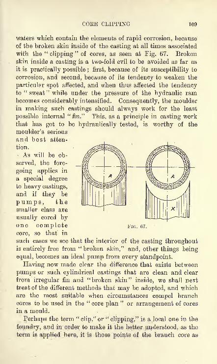
COEE CLIPPING 109
waters which contain the elements of rapid corrosion, because
of the broken skin inside of the casting at all times associated
with the"clipping
"of cores, as seen at Fig. 67. Broken
skin inside a casting is a two-fold evil to be avoided as far as
it is practically possible ; first, because of its susceptibility to
corrosion, and second, because of its tendency to weaken the
particular spot affected, and when thus affected the tendencyto
" sweat"while under the pressure of the hydraulic ram
becomes considerably intensified. Consequently, the moulder
in making such castings should always work for the least
possible internal "fin." This, as a principle in casting workthat has got to be hydraulically tested, is worthy of the
moulder's serious
and best atten-
tion.
As will be ob-
served, the fore-
going applies in
a special degreeto heavy castings,
and if they be
pumps, thesmaller class are
usually cored byone completecore, so that in
such cases we see that the interior of the casting throughoutis entirely free from "broken skin," and, other things being
equal, becomes an ideal pump from every standpoint.
Having now made clear the difference that exists between
pumps or such cylindrical castings that are clean and clear
from irregular fin and "broken skin" inside, we shall next
treat of the different methods that may be adopted, and whichare the most suitable when circumstances compel branch
cores to be used in the"core plan
"or arrangement of cores
in a mould.
Perhaps the term "clip," or
"clipping," is a local one in the
foundry, and in order to make it the better understood, as the
term is applied here, it is those points of the branch core as
FIG. 67.

110 FACTS ON GENERAL FOUNDRY PRACTICE
illustrated at Fig. 67 that the term is derived from hence we
form the "clip branch" to fit up against the main core, A,
Fig. 67. There are three ways of clipping, and to each of
these we direct attention as they appear at Figs. 67, 68, and 69.
Figs. 68 and 69 are illustrations showing the advantage of the"swell," SS, which is on the main core of all cores that are
clipped as illustrated by Figs. 68 and 69. In Fig. 67 we have
the usual way for the moulder to adopt as it involves no
trouble further than forming the clip on the core. This,
however, means more than some jobbing moulders are
capable of doing in workmanlike fashion, while, at the same
time, it is bad in price and practice, whether the core is madein sand or loam. If it should be a sand core that is to be
dealt with, then, by all means, form the clip while it is green ;
but if it be loam with which the branch core is made, the
usual practice is to make it out of the solid core by cardingor otherwise, until the desired finish for fitting it up against
the main core is secured, as seen at Fig. 67. However, there
is still another method, and a speedier one too, although to
some perhaps not very workmanlike. Still, it is in many wayscommendable. The first thing to do 'is to square, in some
way, the end of the branch core preparatory to proceeding to
put the "clip" on ; thereafter place a sufficiently large piece of
paper over the back of the main core for whatever size of
clip we may wish to make ; then, with the core thus prepared,
sufficient loam is placed on the paper, and the branch core
is immediately placed on the main core, and squared on
this bed of soft loam, and by"faking
"and firming all round
the"roughing
"of the clip is completed. This being done,
all is allowed to stiffen, and when finishing it, make sure that
the points of the clips as seen at Fig. 67 are finished clear to
admit of the branch core being placed without breakage while
finding its way up against the main core of the mould for
which it is intended.
Now as to the results in this method of clipping : First of
all, there is the danger of the points being washed away
during the process of pouring the mould, and second, we are
confronted with the evil of a nasty fin at the clip of the branch
which must be broken and "faked" not chipped, as the

COEE CLIPPING 111
position precludes any possibility of doing so but, althoughfaked thus it is, after all, the best that can be done, and the
fin so treated is allowed to pass as a finished job. Tliis
then is what happens with branches in general that are
clipped after the fashion of Fig. 67. The longer the branchthe more difficult is the job, nevertheless wherever this methodof clipping is practised the best fettlers can do no better thanwhat is here suggested.
Why this practice is allowed to go on in many of
what are called up-to-date shops is not easy of explanation,
yet, if the person responsible for the foundry has not a full
appreciation of what particular duty is expected of the cast-
ings passing through his hands he will be content to knockthe work through, irrespective of all other considerations but
his tonnage in the foundry. It
goes without saying that in these
hurry-scurry days of push and
bustle, better methods of economi-
cal working and superior work-
manship are lost sight of altogether.
Hence it is that at times moneyis lost in the foundry that need
not be if the moulder had the
knowledge of what to order, and the pattern-maker had the
will thereafter to make \vhat are frequently but trifles for
the expediting of the work of the moulders, and its conse-
quent saving and better castings for all concerned. This jobof clipping cores is really a case in point, and specially as it
refers to the saddle core-box, not shown, for ramming the
clips on the back of the main core, and as illustrated at Figs. 68
and 69. In these Figs. SS shows the core clips either built
on with loam or ramme.l with sand, either of which is donewhen the main core is finished to size, and thereafter allowed
time to stiffen. These clips as a rule when being rammedare strengthened or supported by sprigs, brads, or irons
driven into the main core and otherwise handled in the waycommon to such cores.
With a clear view of Figs. 68 and 69 (double), along with
what has been stated, the meaning and value of such a
FIG. 68.

11 FACTS ON GENERAL FOUNDRY PRACTICE
method of clipping, as illustrated by the figures in question,
will doubtless be obvious, inasmuch as we avoid the danger of
the points (v. Fig. 67) washing away. In connection with this
point we see at once that the joint, as it occurs through <7,
Fig. 69, can be made an absolute fit, thereby getting a clean
and clear inside skin on the casting, when the branch core is
butted fair up against the main core face SS (and is ripped,
repaired and blackwashed if need be). However, this is not
often resorted to, as these branch core joints when carefully
manipulated have such a small fin, and from the handy position
they occupy on the branch when compared with Fig. 67 no
difficulty whatever
is experienced in
chipping andfinishing an un-
challengeable job.
This method is
more particularly
adapted to the
heavier class of
branch core prac-
tice ; the lighter
class in this divi-
sion of work is
provided for and
illustrated at Fig. 68. In this figure the practice is to all
intents and purposes the same as Fig. 69, the only differ-
ence being the plug end. As will be seen, with such a
core as this sectional elevation shows, when placed in the
mould, the branch D, with its plug end, is simply butted
up against the face of the figure referred to. The plugbranch as shown is for the safety of the core against
rising at the time of casting, and the plug being comparativelya tight fit in its socket secures the branch from other
mishaps common to such class of work, no nails or other
artificial aid being necessary. Briefly, we summarise the
clipping of branch cores thus : adopt Fig. 68 for all dia-
meters up to 6 ins., Fig. 69 for all other sizes above 6 ins.,
and wherever the method of Fig. 67 is practised, then the
FIG. 69.

MACHINE AND SNAP FLASK MOULDING n;j
least that can be said about it is that it is bad and profitless
practice for all concerned.
MACHINE AND SNAP FLASK MOULDING
It is difficult to say exactly when machine moulding was
first introduced in founding. Some would have us believe
it to be quite a modern invention, but, on the contrary, wehave been more or less associated with it for the last thirty-
five years, and during all that period nothing very new or novel
has happened to its mechanism. Indeed, it seems we cannot
get past the ordinary squeeze or force produced by steam,
pneumatic, or hydraulic pressure, and while hand-ramming was
strongly denounced twenty-five years ago, it is now regarded bysome machine specialists in these days as the most economical
system of ramming in all forms of machine moulding. The
foregoing as a rule is not without exceptions, and perhaps the
best advantage to be got in machine moulding (if there be an
advantage at all) is with a certain class of medium work that
is executed by, it may be, thousands of tons, or that which
repeats itself in the fullest sense of the word.
Certain it is, much that was put on the machine platewithin the writer's experience has long since been scrapped,and a return made to the old stereotyped style of bedding in
the floor, resulting in at least 50 per cent, saving with these
castings when compared with the cost of production in what is
known as machine moulding. The above refers to cylindricalwork with attachments where no machine ramming by com-
pression is practicable. However, where the plainest of workis moulded, that is to say, with patterns that are free from
projections, or any attachment of pattern interfering with the
direct force of the ram when pressing, such ideal work oughtto be produced at a rate on the machine not possible off it.
It goes without saying that all machine work is repeatwork. Now this is where many err in calculating costs in the
foundry, and not infrequently when things look rather costlyin this department they quite naturally turn to the mouldingmachine as a panacea for those evils of extraordinary cost.
But, alas, for inexperience ! such changes too frequently fall

114 FACTS ON GENEEAL FOUNDRY PRACTICE
much short of their anticipations. In all such cases look
in the first place to equipment, and make it as good as you
would that of a moulding machine.
Really it is largely a question of equity between floor and
moulding machine, patterns and equipment, and perhaps it is
not too much to say that wherever any piece of mechanism
bears the appellation "machine," and yet, at the same time,
has no record of reducing the physical toil of its operator,
such has, in the author's opinion, no right whatever to be
classed as a machine connected with the industrial pursuits.
It is a pity that it is so, especially with founding, where so
much abnormal toil is done. Further, it is very doubtful if
more can ever be done by machines than is at present accom-
plished. Moulding as a craft has many peculiarities of its
own, for, while form, contour, and efficiency suffices in most
occupations, such is very far from meeting the wants
fundamental to moulding.
Consequently, machine moulding such as is known in found-
ing becomes very circumscribed in scope and practice, and as
a result we may take it that the jobbing moulder will remain
much in the same place in the future as he has been in the
past, at least, in so far as mechanical aid in his business is con-
cerned. But, on the other hand, he will have the advantage,
as before, of outshining the machine moulder by the scope of
his work which requires him to use his intelligence ;and to
this he should always aspire, as by doing so he will be the
better man not only for himself, but for his employer also.
All the same, machine moulding, in the author's opinion,
has come to stay, but we can only regard it as being a substi-
tute with the" tub
"or
" bench"
for small work, where
plates and turn-over-boards are much the same as for
machine moulding. Of course, with the machine we usually
have the advantage of drawing the pattern or plate by a
lever, and rapping it at one and the same time, which is
undoubtedly an advantage in many cases.
It may be said that the machine has the advantage of
grouping many pieces on one plate, but it should be understood
that this same plate which accounts for so many castings in a
box, as a rule, can be made as quickly off the machine as on it.

MACHINE AND SNAP FLASK MOULDING 115
Indeed, where the boxes are a little unwieldly for lifting on
and off the table of certain types of hand-ramming machines,in many such 'cases the operator prefers to make his joboff the machine altogether and with better results for all
concerned, thus proving that whatever increased output
may be accredited to the machine in question is rather due
to its equipment and not to mechanism at all. But whatever
better side there may be to this question, we ungrudgingly
give it, so that wherever machine and plant can adapt them-
selves to advantage by reducing cost of production, then byall means let it be done.
There is but little more to say on this question beyond the
need there is for careful ramming in this class of work. All
gates should be part of the patterns, and so save time in
cutting them, leaving nothing to be done except prepare the
mould for pouring. Use but little water* when swabbing
patterns, i.e., if the castings are light metals, previous to
rapping and drawing ;this will considerably free the castings
from hard, brittle, and white fins and irregular edges. Andshould the castings be of light metal section, lift them the
same day that they are poured, so as to prevent them rusting
by lying too long in their boxes."Snap Flask
"is a special form of moulding whereby any
number of castings may be secured from the same moulding-box. This particular box, which is gripped and hinged at
opposite corners, may be of round, square, or oblong shape,
each of which is adapted for the greatest economy of sand
and convenience in handling two very important factors in
the cheap production of the class of work for which the snapflask is intended.
This system has for many years been in much favour in
light work foundries, where a large amount of work commonto
" bench"
or" tub
"was done formerly, and where the
necessary plant formed a considerable asset, but by the intro-
duction of one snap-flask box in the day's work of each moulder
on this class of work, instead of ten, twenty, or perhaps more,where each casting or box of castings had to count for the
same number of boxes, the economy in plant must be obvious.
* Wherever this is practicable.i 2

116 FACTS ON GENERAL FOUNDRY PRACTICE
These boxes are made light and handy, and may either be
made to work on the machine or off it. In every case these
boxes are barless, but must have extra good"kep
"in the
form of say a half-inch projection running round the inside,
top, and bottom of both boxes alike. In proceeding, first the
drag is rammed and placed where it is to be poured ; second,
the top flask is rammed and closed on top of its neighbour.This done the mould is complete, is next planted where it is
to be cast, and by the snapping of the gripper from its keeperthe box is relieved and again prepared for repeating the
operation of making another of the moulds just completed.
MOULDING CYLINDERS AND CYLINDER CORES
It is generally admitted amongst moulders that no class of
work gives more trouble and annoyance than the casting of
cylinders, not only from the intricacies which often accom-
pany the job, but the general nature of it. From the time it
comes into the foundry until cast and passed safely throughthe machinist department and hydraulically tested no one
can be sure that his work is good.
Ramming. Of course the natural beginning is the rammingof the job, after which will be considered other matters as
they develop while working out the mould to the final stage
of pouring. The ramming of the job is of the utmost import-ance in securing a good casting, and the moulder who
thoroughly understands how to ram his work has gained the
mastery of one of the chief points which help to make an
intelligent and successful moulder. Certainly there is not so
much danger in ramming a dry-sand mould as there is in the
ramming of a green-sand one, but still, too much hard rammingwill not do for dry sand, of which cylinder moulds are commonlymade. Therefore, the surest and safest rule to go by is to
ram as if it were a green-sand job.
Venting. As regards venting it is not absolutely necessary
that this should be done, except there be projections, or as
they are commonly known to the moulder,"pockets," as the
drying of the mould makes the sand so porous that the air
passes quite freely from the mould without the aid of direct

MOULDING CYLINDEBS AND CYLINDEE CORES 117
venting. This and the expansion of the irons and gaggers
usually interspersed in dry-sand moulding make good venting,and especially is this the case with the top-parts, where
hangers are usually hung on the bars of the box, which givefree exit of the gases by their exposure. Needless to say,
"irons" and such like do not make vents, but the effects
from their use in dry-sand moulding give more or less the
necessary space for relieving a mould of its gases at the time
of pouring. This is brought about by expansion from the
heat of drying the moulds, and when these are taken from the
stove, the gaggers or hangers previously expanded become
considerably contracted previous to casting, and as a result
the space for venting is thus formed. Another reason whydry sand does not require the same venting as is given to
green sand is that by drying a sand mould at least one-half
of its gas-forming constituents is destroyed, so between the
former and the latter we see at a glance that venting of a truly
dry-sand mould unless there are projections as has been
mentioned is seldom imperative. Indeed, experience inclines
more to"sprigging
" and "ironing
"judiciously than venting
in dry sand moulding.
Sprigging. This is very often overdone, but it must be
attended to with discrimination. There is no necessity for
sprigging unless it be to protect the mould or some part that
may have started with the drawing of the pattern, and the
better we "iron
"a job of this class in ramming, the fewer
sprigs will be used. This can only apply to cylinder moulding ;
that which is moulded and dried in the floor requires special
consideration for itself which we cannot touch upon at present.
Finishing the Mould. Finishing is one of the divisions in
moulding where the man who is endowed with artistic instincts
has an opportunity for showing his gifts. But it does not
always follow that such men turn out the most beautiful
castings. On the contrary, some men who are thus giftedmake but very commonplace moulders, simply because the
mind's eye has never been trained to read anything in foundrypractice beyond the surface. A beautiful surface, and a
symmetrically complete finished mould, may after all turn out
a scab of a casting, Such completeness in form and beaut}7
118 PACTS ON GENERAL FOUNDRY PRACTICE
may be the dominant factor of success in many trades, but it
is certainly not so in moulding. The fundamentals to be
secured which underlie the beauty of a well-finished casting
are, first, efficiency of the mould to withstand ferrostatic
pressure, and second, venting. These are the prime factors
to be attended to before finishing a mould can be proceededwith in safety. Finished on the lines suggested, there is everychance of a good casting being the result in so far as those
points referred to.
The moulder's first duty at the moment of drawing his
pattern is to prove that his mould in every part is sufficient
before he applies a tool to finish it. He must first firm, sprig,
and vent, if need be, and when these are completed to his
satisfaction, use the tools for the rest, but avoid polishing to
the extent of hiding the grain of the sands, a mistake too often
committed, and for which scabbing is most frequently account-
able in green-sand moulding, and in dry sand, scaling and
blistering, according to the position of casting. Horizontal
surfaces are very liable to show these defects, while vertical
surfaces are comparatively free from such danger.
Further, as soon as the pattern is" drawn " and I need
hardly say that the utmost care should be taken to secure a
good" draw "
care should be taken to sleak down the joint,
and to see that every part which may have started is put back
into its proper place, so that when it comes to the "closing
"
of the mould, every part may be fair and free from crushing.Some moulders seem to think that because it is a dry-sandmould any amount of water showered on it before finishingis beneficial, but such is not the case. No doubt water is
absolutely essential in making a strong mould, but if it is
used indiscriminately so as to cause the mould to be glazed,
the consequence will be that the black-wash will not adhere to
it, and, as a natural result, there is every likelihood that the
skin will be covered with black-wash blisters in the drying of
the mould. It is thus better to avoid the free use of water ;
but if it be desirable to strengthen any weak part, a little puton after it is finished will do good, i.e., if there is time for its
complete absorption before black-washing.But it is not my intention to treat in detail every minor
MOULDING CYLINDERS AND CYLINDER CORES 119
point relative to, or connected with, the making of the mould,
believing that such would be of little value to the practical
man and of less interest to the uninitiated. Hence it is
unnecessary to treat at any great length concerning the
working of the black-wash, further than to say that the drier
the mould is before being black-washed the better, and like-
wise allowing it sufficient time to stiffen before beingsleaked will materially assist in getting a good skin on the
casting. Assuming the mould to have been black-washed with
an ordinary mineral black-wash, the common practice is to
rough-sleek, then dust with plumbago over the surface, and
afterwards finish off. This done, a thin wash with plumbagomade or mixed with either clean or gum water, brings out
the best skin possible on a cylinder casting moulded either in
dry sand or loam.
Core making. The core maker, as previously stated, should
be careful to avoid ramming too hard, as any core so treated
is difficult to vent, and likewise difficult for the dresser or
fettler to clean from the casting. He must also take par-
ticular care to have a good clear vent, as this is the all-impor-
tant factor in core making, and must also be careful before
black-washing to see that the surface of the core is entirelyfree from glaze, because there is nothing more dangerous in
creating"
blisters "on the top surface of a casting than a core
with a glazed surface. The term blister as used in the foundryis a little ambiguous, because of the fact that no disfiguration,
as is common to blister steel, or the formation of a blister any-where else, has any similarity to a blister on a casting. Ablister is a blowhole confined, as a rule, to horizontal surfaces,
and may be any length, say from in. to 12 ins. long, and its
greatest depth may be \ in. only."Blister
"in foundry parlance is the term used to denote
a surface defect that is formed by imprisoned gas which
invariably is the result of a hard, dense, or glazed core, lyingin the horizontal position. Blisters, unless broken by accident,
do not, as a rule, show themselves unless by colour, or the
sense of sound, to a practical man. The symmetrical surface
of a casting usually remains the same with or without them,but when located, and the thin skin of iron which conceals

120 FACTS ON GENERAL FOUNDRY PRACTICE
them is broken, invariably we find the surface which deter-
mines their extent to be as smooth as a piece of earthenware.
Now in cylinder-sand core making there must be special care
taken of the cores or parts of cores that have to occupy a
horizontal position while casting, for, no matter with what
pressure a core may be favoured, glazed surfaces must be
avoided if we wish to avoid blistering, which is common to
flat, or horizontal surfaces. See "Blowholes," Figs. 16, 17
and 18.
There are many who hold the opinion that this error, in a
general way, is due to chaplets. No doubt a chaplet which is not
clean and is corroded with rust will invariably have a bad effect ;
yet, after a careful and more than casual study of the subject, 1
believe that greater dangers arise from a hard and glazed core.
The following is an example : I was once engaged making a
class of cylinders which had a crown core, having from2 to 4 ft. of surface, and as this core required no chapletson its plain surface it may perhaps astonish my readers to
know that I was very much annoyed with blisters. Various
things were suggested and tried without success. UltimatelyI tried ''carding," or roughing of the surface, which had the
desired effect and' put an end to the annoyance. From this
it must be obvious that blisters may be attributed to other
causes than chaplets. Chaplets that are not clean should be
burned, cleaned, oiled, or creosoted, and if this be attended to
the most satisfactory results attainable should follow. See"Chaplets," p. 42.
Thus far the foregoing completes the moulding proper, in
a somewhat summarised manner, and we will now treat of the
closing and casting of the mould.
Closing. This is, admittedly, the most intricate part of
the whole job, and also the dirtiest part ; but where cylinder
casting is specialised, the moulders showing the greatestacumen in their craft as moulders are the men selected for
coring, closing, and casting. Immediately on taking the
mould from the stove or oven the moulder's first duty is
to see that it is thoroughly dried before proceeding with the"closing." He should be satisfied that when casting it there
will be no blowing from the damp which invariably gathers

MOULDING CYLINDEES AND CYLINDEE CORES 121
in moulds that are not properly dried. But should there
be urgent necessity to proceed with the casting in the face of
such adverse circumstances, the mould should remain open as
long as possible, so that it may be comparatively cold before
the top part or cope is put on for the last time, because a
mould with a great heat in it, and only half dried when closed
in this condition, quickly generates steam, which condenses
about the waste or hemp in the risers', and causes a great
commotion, the metal bubbling and blowing as it fills in the
riser basins at the time of casting.
It will be obvious that these remarks only apply to the
smaller cylinders that are cored, closed, and cast in one day.
Further, the greatest care should be exercised in securing the
cores with the chaplets after the thicknesses have all been
adjusted, which very often is the means of saving much time
and trouble;for to unfasten a core that has been secured or
jammed frequently ends in some part of the core being dis-
placed or broken ; hence the necessity of having the thicknesses
all properly adjusted before finally jamming the chaplets.
The next thing to be attended to is the securing of the vents,
which cannot be too carefully done, as there is nothing more
depressing to an honest working moulder than to see his whole
work going to destruction before his eyes through lack of
proper vents to allow the gases to get away freely from the
cores, thus causing a bad casting which might have been
saved by the exercise of proper care. With cylinders that
have the steam chest or casing cast on them it is necessaryfor the gases from the steam and exhaust ports to pass
through the heart of the casing core. The simplest mannerof venting in this case is to daub the joints of the above with
white or any other suitable loam ; then clear the vents of the
ports and exhaust, fill the heart of the casing with fine ashes, and
conduct the entire vent through the joint of the boxes, or passit up through the casing bearing in the top part by the aid
of a suitable tube or otherwise.
This method of grouping all vents into one by the use of
suitable ashes in the heart of the casing core, as explained
here, and in " loam moulding," prevents a possible accumu-
lation of moisture, which naturally follows the use of individual

122 FACTS ON GENERAL FOUNDRY PRACTICE
vent pins that are sometimes used and rammed with sandin the heart of these casing cores. The ashes method of
venting thus may be said to be absolutely safe, but the vent
pins used as mentioned with the ramming of damp sand, is,
to say the least of it, not good practice.
Position of Casting. There is great diversity of opinion
amongst engineers as to the position of casting cylinders; some
prefer to have them cast vertically, or on end, others wantthem cast horizontally. The majority, I believe, favour the
former position, maintaining that to cast cylinders horizontallycauses dirt to stick about the barrel and create a faulty bore.
But in the other position of vertical casting there is
the common complaint of bad flanges on the top, or gate
end, of the casting which only comesto view when what is technicallyknown as the sinking head is cut off.
These imperfections are created during'the process of solidification of the
metal in the mould, which continues
till the fluid metal is thoroughly set,
the dirt, or scoria, common to the
metal having found its way, at the
time of pouring, into the sinking head, the place specially
designed for its reception.
These shrink cavities are always greatest on cylinders that
have a disproportionate thickness, or parts attached to the top
flange, as it is seldom, if ever, that a plain barrel of normal
thickness, is thus affected. Now the best thing that can be
done for this is to feed the casting as long as the metal is
fluid; but unless provision is made for the feeders, the feedingwill be useless, consequently the sinking-head must be madeheavier so that it may be the last part to solidify, as shownin Fig 70. The advantage of keeping the sinking-head fluid
until all the parts are set is apparent, as if it be thus kept
fluid, and the casting fed, shrink-holes or such like will in
a great measure be minimised, if not entirely removed in the
case of cylinders that are cast on end.
Should disproportionate thickness of metal be confined to
one side of a cylinder only, such as is the case with some
FIG. 70.

MOULDING CYLINDEES AND CYLINDEE COEES 123
locomotive cylinders, and where the framing flange is on the
same side as the valve face, make the face of the flange (whichis the top flange) \ in. or f in. thicker, and the extra thickness
in the sinking-head on the disproportionate side only ; the
same to be tapered off in eccentric-like section. Having thus
formed a heavier sinking-head as indicated, it admits of heavier
flow-gates being made, which gates should be made practically
as large as the thickness of the metal contained in the sinking-head will admit. And let it be remembered that the only
preventative against cavities is compression and feeding well
by some means or other. See to it that spongy parts as
indicated by the arrows in Fig. 71 are in immediate contact
with the feeder, otherwise such parts will undoubtedly be
faulty, or the casting maybe irretrievably lost.*
And now as to the hori-
zontal position, which has
many commendable features
about it, although it is not
without its troubles also.
In this position we get the
most perfect valve face pos-
sible, and valve rod paps uni-
formly solid, while the barrel
flange faces, which are so apt to give trouble to the vertically
cast cylinders (top end only), are entirely sound and perfect.
But with this position, as with all others, no matter how we
cast, the dirt is always to be found in 'some undesirable spot,
so in this case it is in the extreme bottom part of the barrel
that all the trouble with dirt locates itself. This is worthyof note, because it mystifies many to find dirt on what theyconsider the bottom part of the barrel, as the bottom or face
of all castings invariably turn out the most solid and
cleanest part. But on closer examination it will be found
that the top of the mould, paradoxically, is at this particular
* For some years some have adopted sinking-heads of abnormal pro-
portions, these being anywhere between 1 ft. and 3 ft. in depth, and from3 ins. to 4 ins. thick. Notwithstanding all this extra metal, shrink
cavities at times appear on the " face" when the sinking-head is cut off.
FIG. 71.

124 FACTS ON GENERAL FOUNDRY PRACTICE
place the bottom side of the core, a point which ought to be
remembered when discussing the subject of a horizontal cylinder
casting. In order to make this perfectly clear, it must be
realised that the metal, collecting first on the extreme bottom,
on rising comes in immediate contact with the core, and what-
ever dirt may be floating on the surface at this point has a
strong inclination to remain there. Hence the difficulty of
getting the barrels of cylinders perfectly clean when cast on
their flat. Nevertheless, by adopting special methods of
gating, the horizontal and declivity positions have longbeen the fixed practice of casting in some of the best loco-
motive shops in the kingdom. Some gate one way and
some another; but there is one way of gating that should be
avoided, and yet it is the most natural way in general practice
namely, to gate off the joint. Now to do this is undoubtedlybad practice, as the metal does not come in immediate contact
with the bottom of the barrel at the moment of pouring, such
as is the case with an admission gate at a lower part of the
casting. Consequently a greater percentage of scoria is
developed before the metal- comes in contact with the bottom
of the core, and as the pressure increases with the filling of
the mould, this dirt or scoria clings more tenaciously on the
part referred to, and by its remaining there, the hopes of
securing a good casting are small indeed. This is a stumblingblock to many, as has been said, as they maintain that all
dirt, kish, or impurities must find their way to the top of the
mould. Such is quite true, but it must not be forgotten that
moulds of intricate design have more "top surfaces
"than the
one that is confined to the highest part of a mould. More-
over, we never saw a faulty bore on the extreme top side
of a cylinder-barrel casting, when cast in the horizontal
position ; even although this part was not all that could be
desired, the "bore" invariably turned out perfectly clean, all
impurities escaping to the higher extremities of the casting.
Again it has to be borne in mind that many excellent
cylinders have been cast vertically without the aid of a
sinking-head at all, and such are the variety of opinions in
foundry practice that he would be very bold who said that
any position was supremely correct. But in moulding, as

MOULDING CYLINDERS AND CYLINDER CORES 125
in many other things, what may be lauded in one district is
condemned in another ;this we may take to be the inevitable
experience in foundry practice.
But, after all is said and done from a moulder's point of
view, the details of pouring these castings must be of a very
superior order. Apart altogether from the mixing and melt-
ing of the metal which, of course, does not belong to the
moulder who makes the job there must be a clean ladle con-
taining good and clean metal, well skimmed and cast at the
right temperature, otherwise the best efforts made by the best
moulders possible will be lost entirely.
Much mischief at times is caused at the start of pouring bydirt getting down the upright gate ;
and it must be noted that
this mistake is more dangerous in the horizontal than in the
vertical position. But in casting in the former position, andin order to avoid this mistake, some try the plug gate for
greater safety in pouring. The pouring basin in this practicehas but one upright gate, which is plugged before starting to
pour ; and after starting, and the basin being filled while the
pouring is going on, the plug is withdrawn at the propertime. The pouring being constant, the job is expectedto be cast without any dirt finding its way into the mould
; at
least, such is the idea of some, and although it may appear a
little Utopian to others, it is here and there in constant practice.
Writing from the standpoint of lengthy experience in
moulding and casting cylinders for wind, water, steam, gas,
and oil, and taking these in their broadest application as theyrelate to successful moulding and casting in the foundry, I
say, as a principal, cast vertically and feed well. Of course,
in the casting of cylinders there must be exceptions to this
rule, but not with those that are jacketed, a class which, to do
justice, requires to be dealt with separately.
'JACKETED CYLINDERS
In this division of cylinder moulding we have all the cores
common to the various types of cylinders, and the jacket core
in addition, so that all jacket cylinders must in consequencebe more critical to mould and cast than those cylinders that are

126 FACTS ON GENERAL FOUNDRY PRACTICE
not jacketed. This class of cylinder is fairly well representedin steam, gas, and petrol engines. In some localities,
when compared with twenty-five years ago, the jacketed steam
cylinder casting is now almost a thing of the past. Happilyfor both moulder and mechanic, a better way has been found
of forming the jacket in cylinders by the fitting into the
cylinder body that handy article known as the cylinder liner.
But the gas engine cylinder in general use is still cylinder and
liner combined in one casting. The petrol cylinder of the
motor car comes next with its complications and delicacy of
jacket cores, which have given so much trouble to many, and
have created difficulties that have been very hard indeed to
overcome. These three different jacket cores will form the
work of this division of cylinder moulding, notwithstandingthe wide field of interesting cylinder moulding practice allied
thereto, and what has been given in the previous section
on cylinder casting makes it unnecessary to deal with all the
details in jacket cylinder moulding.Steam Cylinder Jacket Cores. These may be classed as of
two different types first, dry-sand cylinder moulding ; second,
loam moulding. When made for dry-sand castings, these
jacket cores are usually made in halves, but when made for
loam castings, they form, with very few exceptions, one
complete core, and this is by far the safest and surest way of
handling these cores. Jacket cores at their thickest seldom
measure more than 2J ins. thick, even with the largest
diameters of steam cylinders, and, of course, the thicker the
core can be made the safer it is for the moulder.
(1) Sand Jacket Core. When moulding a jacket cylinder
in dry sand, the core, as has been said, is made in halves ; one
is fixed on the bottom half of the mould, while the other is
fastened and hung firmly to the top part in such a way as to
ensure absolute fixity without slackness or weakness of anykind, otherwise there is not a great chance of the casting
being a good one. This procedure is necessary on account of
the jacket core being entirely enshrouded in metal, and by
fixing it thus, the plug cores on both ends of the jacket for
venting and fettling the casting are all made good in this
respect previously to commencing to core the cylinder as a

JACKETED CYLINDERS 127
whole. The core-box for this method of working these cores
is usually made of a shell type, i.e., half circle, full length, and
entirely open to the inside diameter of core. These half cores
are better when made in loam, and should not be attemptedin sand, where plug vents and the hanging of the core in the
top part as described is imperative ; but, if open entirely at one
end, a sand core should do when the hanging of the top half of
the core is not necessary. The sand suitable for jacket cores
will be found in "core sands," and, if made in loam, that
which is mixed for"pistons
"will suit these cores also. The
vents must be brought right up through the top when cast
vertically, and should be made by bedding |-in. round iron
rods at suitable "divides." The loam should be tucked round
the core iron in the box, and each core should be providedwith a tube rigidly fixed to the core iron, hard up against the
end of the core box, so that the plug cores, which are madewith a tin tube in their centres, and projecting about an inch
beyond the end of the core, telescope firmly into those of the
jacket core just mentioned. The plug cores in the flanges
should be placed so as to come in between the bolt holes of the
flanges, and thus avoid confusion and the possible wastage of
the flanges, which would mean the loss of the casting.
(2) Jacket Cores in Loam Moulding. The difficulties and
dangers connected with the making and manipulating of
jacket cylinder cores in loam moulding are, of course, very great,
and it is not too much to say that it takes a clever loammoulder with some engineering capacity to undertake success-
fully the carrying out of all the details in making these cores,
and, before all could be fully explained, many more figuresthan the one employed, namely, Fig. 72, would be required to"
illustrate the modus operandi in full. Obviously this cannot be
done, but it is hoped that the instructions given in Fig. 72
will suffice for those who may be specially interested.
Although the various methods of engineering these cores
might be given, we shall only take the one thought best, nomatter from what standpoint it be taken, and for that purposelet us keep in view Fig. 72 for our object lesson. This figure
represents a jacket core in sectional elevation, with dimen-
sions 6 ft. by 3 ft. by 2^- ins. thick ; and it may be said in

12S FACTS ON GENERAL FOUNDRY PRACTICE
passing that the materials and workmanship, and all pertain-
ing thereto, will answer equally well for cylinder jacket cores
of larger or smaller diameters.
It should be stated that the building of jacket cores requires
a special loam brick, made of porous river-sand loam. These
FIG. 72.
bricks should measure about 3 ins. by 2 ins. by 2 ins., and
should have a small groove on one or both sides to admit the
small hay rope which is inserted round every alternate course
of loam brick during the operation of building these jacket
cores. It must also be distinctly understood that these small
hay rope vents in every second course must have their ends
inserted right into the holes of the vent tubes prepared for
them, as shown at Fig. 72.

JACKETED CYLINDERS 129
In the building of jacket cylinders in loam there should be
a circle plate about 6 ins. or 8 ins. broad, with holes cast in it
all round " between the bolt holes of the flanges"
of the
casting. These holes are for the vent tubes (Fig. 72), which are
screwed at both ends of the jacket core for binding purposes, as
seen at Fig. 72, and the circle plate B of the same figure
should be placed 7 ins. or 8 ins. from the bottom of the mould,thus leaving the brick in immediate touch with the base or
bottom plate, and so give abundance of clearance to work the
bottom nut, which secures the vent tubes to the circle plate B.
The tubes in question serve the double purpose of core-iron
standards, and vents, the ends of which pass up through holes
cast in the top plate of the mould (not shown) for their recep-
tion, so that the projecting ends of the tubes as seen are
shown to fit into whatever purpose of safety may be adoptedat the time of casting.
The number of tubes in a jacket core can only be deter-
mined by circumstances, but to cast a hole on the bottom
plate B (Fig. 72) for every second bolt in the flange of the
cylinder casting, is good and safe practice, for, no matter how
many holes we may use for tubes, such perforation as these
holes form on the plate is all the better for venting purposeson the face of the mould. Besides, with so many holes, that
in no case can do harm, we can scarcely be at a loss when
arranging the tubes previously to building the core. In
passing tubes through the plate for bolting, these tubes must
have a double nut that is to say, one on either side of the
plate B. This arrangement of double nuts makes the tubes
in question an absolute fixture, consequently no danger need
be apprehended as to their shifting up or down. The distance
of these tubes may vary from 12 ins. to 20 ins. on the
circle of the core, and their distribution and number dependson the diameter of the respective cores. With the vent tubes
which compose the standards of the core iron, rings D(Fig. 72) cast | in. thick and J in. a side less than the thick-
ness of the core should be interspersed at a distance of every6 ins. or 8 ins. while building the core in the vertical position.
A pattern should be made for these rings, and holes cast in
them suitable for the tubes to pass freely through in the processF.P. K

130 FACTS ON GENERAL FOUNDRY PRACTICE
of building the core;and other small holes, over and above
the tube holes, will be an advantage in the way of ventingthe core.
Thus far we have dealt with venting, and some of the
materials requisite for making a vertical loam cylinder mould,but especially as it refers to the making of a jacket core for it.
Having accomplished this briefly, it only remains to be said
that jacket cylinder cores in loam moulding are all made from
bosses, as shown at F, Fig. 72. These bosses are built with
black loam and brick on the base plate of their respective jobs,
as seen at A, Fig. 72, and are finished off with black loam, which
soon stiffens, thus finishing the boss for its work of making the
core.
The tubes being fixed as suggested, and the face of the
mould being prepared for placing the pieces of wood C all
round, which form the thickness of the flange, and the
temporary flange being placed, we now proceed to build the
core. By referring to Fig. 72 it will be observed that the
first thing to be done here is to bed on the prodded ring D I,
and have it tucked up with loam as shown. This, being the base
or foundation of the core, must be done in good workmanlike
fashion, and thereafter proceed with the structure as mentioned,and illustrated in the figure. Special care must be taken when
placing the last ring D 2, with its prods uppermost, that
these prods are kept about J in. clear of the loam board.
Having satisfied ourselves that the prods are clear of the loam
board, this plate, or ring, is bound with the nuts E, made for
the tubes, as previously mentioned ;and with the vents secured
on this uppermost part of the core, the whole core is trimmed,
roughed, and finished off with sieved loam according to loam
core practice.
Thus the core stands completed according to sizes wanted,
and is allowed time to stiffen before the boss F can be taken
down for finishing. In due time the boss is removed, togetherwith the wood C or temporary flange pattern on the bottom,
which is in pieces, and when all is finished, core and bottom
part of the mould, which has now become as one combined
structure, is passed into the stove for drying. And here weleave what is considered the best and safest method of

JACKETED CYLINDERS 131
handling a jacket cylinder core, when moulding these castings
in loam. Jacket cylinders, whether large or small, should,
whenever possible, be made in loam. Dry-sand is not
advisable wherever loam is possible.
Gas Engine Cylinder Jacket Cores. This core in our experi-
ence has proved the safest of the kind made in sand, and
anything up to 30 horse-power has always been considered
good practice in sand ; beyond this size it is safer to have a
loam core. One good feature of these jacket cores comes from
the openness at one or both ends of the barrel, which (1)
makes venting comparatively easy ; (2) fettling still easier ;
and (3) gives abundance of"bearing
"wherewith to rest those
cores three very essential functions that the gas engine
cylinder jacket core provides by the nature of its design, but are
almost, if not altogether, denied the steam jacket cylinder core
just referred to. Hence the need for the plug cores and other
devices in casting steam jacketed cylinders.
There is still here one other very important point of con-
trast, namely, expansion of core, which takes place immediatelyafter the mould is cast. With the first jacket core considered,
it was referred to as being entirely enshrouded in metal.
Now, with such a core, it will at once be admitted that its
expansion is inevitable, and to this much of the defectiveness
common to steam jacketed cylinders, on the top ends, is doubt-
less due- Not only do we get the swell on the basins visible
after pouring, but the expansion also from the core while the
metal is in the plastic state, which is without doubt contribu-
tory to the mischief done, namely, shrinkholes and want of
density common to the top ends of those castings. This evil
has more than added its quota of those castings consigned to
the scrap heap, which otherwise should have been good cast-
ings. If engineers could, or would, have designed for the openend in the steam cylinder jacketed core, as is generally the case
with the gas engine cylinder, very much of the heavy losses
hitherto experienced in steam cylinder jacketed castings wouldhave been averted. But just because of the losses referred to,
the cylinder "liner" was introduced, a change which has
given so much satisfaction to all concerned, and for which the
founder is doubly thankful.
K 2

132 FACTS ON GENERAL FOUNDRY PRACTICE
But let us keep to the gas engine cylinder jacket cores;
and what has been said thereon refers to sand moulding of
those cylinders whose barrel is divided or parted, the same as
a common pipe, therefore these jacket cores are divided longi-
tudinally in halves the same way. These cores are placed in
the mould on their bearings and, if need be, supported by
chaplets. No plug vent cores being needed, the top half core
is simply laid on the top of its neighbour previously placed in
the bottom of. the mould. The simplicity of this when com-
pared with the cores requiring"plug vents," and the jacket
core hung to the top as previously mentioned in sand mould-
ing, requires no further comment to show its advantages, and
as a result jacket cylinders for gas engines become a pleasanter
job to a moulder, because of the comparatively greater safety
experienced in making them.
Core Sands, Core Irons, and Cores. Sands suitable for
these cores are usually made from rock-sand, loam, and milled
dry-sand facing sand. Some have a strong inclination for
horse dung loam, and believe it to be an indispensable con-
stituent of core sand, but in no case do we recognise this
dirty practice.1 Fifteen per cent, of sawdust to whatever
quantity of sand mixed will take the place of this obnoxious
commodity. It would be gratifying to think that this use of
horse dung was a thing of the past, but it is not so, as this
manure account in many up-to-date foundries still forms an
item of considerable cost. Eiver-sand loam is chosen bysome for its porous and plastic qualities. This is not neces-
sary, as the sawdust imparts the first quality and may even
overdo it;but for safety in this, a handful of core gum to
half a barrowful of sand of the grade mentioned will makethe core when baked, quite sufficiently strong for handlingand perfectly safe for casting also. If flour be used instead of
gum, multiply the quantity by three. This mixture of core
sand is very easily fettled, doubtless due to the destruction of
the sawdust by the red hot casting.
Core Irons. These jacket sand cores in halves when made
by a good core-maker are quite safe with straight irons placed
1 Of course, moulders are usually men of many shifts, and if horse
manure is easier got than sawdust, use it.

JACKETED CYLINDERS 133
at suitable distances longitudinally in the core-box; other
circular cast irons f$ in. by 1 in. or 1J ins. may be placed
transversely at suitable distances from end to end of the core-
box. These irons as stated will do all that is required to
make a throughly good and strong core. Indeed, while coring
the job with such core irons for these jacket cylinder cores,
no fear of breakage need be apprehended by taking hold of
them anywhere with ordinary caution while in the act of
placing them in the mould in their respective positions. This
again shows the simplicity and convenience of the gas cylinder
jacket, when compared with the steam cylinder jacket core.
Jacketed Cylinder Cores for Petrol Engines. The petrol
engine, the latest invention requiring a cylinder jacket core,
has put many good moulders into difficult and unenviable
positions at times, by losses with these cylinder castings which
have been occasionally computed at as high as 75 per cent.
The comparatively few years' experience in the internal com-
bustion engine trade has shown many difficulties in core
making which, at the initial stage of its existence, seemed
insurmountable, through the delicacy of manipulating the
jacket cylinder cores. But time has proved all this trouble to
be a lack of experience, as we have abundance of evidence to
prove that wherever introduced, and after the elementarydetails were mastered, the trouble of "blow ups
" and blow-
holes in those cylinder castings in a very great measure
disappeared, and ultimately no unusual difficulties were
experienced in their production.The great question with the majority was the compounding
of the core sand used ;at least such seemed to be the popular
belief. Now, however much value may be put on this question
of sand, we are afraid it is too frequently over-estimated, and
this has been the same throughout all our experience of core
making difficulties. Back in the early seventies when the gas
engine was in its infancy and probably before the petrol
engine had an existence, the casting of small steam cylinders
with their tiny steam ports about J in. or f in. thick was
always matter for much concern. In the mixing of core sands
for this class of work it was in most cases a " fanciful com-
pound"
of one ingredient killing, another ;these in some

134 FACTS ON GENERAL FOUNDBY PEACTICE
cases counted as many as half a dozen different constituents
of one kind and another. In this connection one would almost
think in the motor cylinder castings trade that history had
repeated itself with more intense ridiculousness in some of these
fancy core sand mixtures. In proof of this we give an up-to-
date recipe thus :
" Two handfuls of gritty dust from near the
roof spouting, two-and-a-half shovels of red sand, two shovels of
black sand, and half teacupful of core gum." This is copied to
prove our contention, but hardly calls for further comment.
Having so far explained the true value of things in this
respect to a moulder, and which is borne out by experience,
advisedly we say, a great deal more depends on the moulder
than the sand. A good moulder or core-maker will find his
sand and make it suitable, but the sand will not make the
moulder suitable to the sand. With the former many of the
fancy mixtures disappear, and with the latter they usually
multiply. There is no need for any recipe here further than
to say that, what makes a good cylinder" steam port core,"
will also make good"petrol engine cores," and if there be
difference at all, it need only be in the grade, the former being
passed through a J-in. or f-in. mesh, the latter through $ in.
or J in. for the jacketed portion of the cores.
Core irons for motor cylinder jackets are usually madefrom ^ in. thick iron for the longitudinal lengths, and for
transverse in. thick will do. In some cases after fitting the
core iron it may be necessary to solder it at different parts so
as to have a strong and efficient core iron, but in other cases
all that is necessary is simply to place the core irons with care,
as illustrated by the jacket cores of the gas engine cylinders.
Wax vent wire may be said to be indispensable for venting
purposes ; but above all, make vents good and clear, and do
not apply ashes at all. Avoid letting the core become con-
taminated with wax from the vent wire, and blackwash the
cores green.In the three types of jacket cores dealt with it will be
obvious that the progression as represented in this class of
work has been stepwise : (1) the large jackets of the steam
cylinders ; (2) the medium of the gas engines ; and, (3) the
small jacket core of the petrol cylinder, that has come into

CORE-SANDS 135
such prominence in foundry work during the last few years,
and according to some has done more than anything else to
develop the highest degree of skill, and accuracy in foundry
practice. The relationship between the jacket cores of the
loam made cylinders and similar cores of the gas engine is
considerable, and although the principle is much the same in
practice, still in certain respects they are quite different.
But again, when comparison is made between the smaller
sizes of the gas engine and the larger sizes of the petrol
engine, a much nearer relationship is found to exist, thus
bringing the moulder who has experience in gas engine
cylinder casting in close touch with petrol cylinder practice.
The materials and methods in the making of those two
jacket cores have much in common with each other. There-
fore, the gas engine jacket cylinder ought to be a good
stepping-stone to the moulding of a somewhat similar class of
cylinder castings for the motor castings trade.
COEE-SANDS
In the matter of core-sand some moulders have greatfaith in strange nostrums, and the various antidotes
applied for real or imaginary evils have at times been amus-
ing. And just one case in point. In my early experience,
and while working in a certain shop, I saw a small steam
cylinder moulded, which was lost three consecutive times,
the loss in each case being attributed to the cores. In
the making of the fourth set of cores the moulder resorted to
the compounding of potatoes with sea sand to the necessary
consistency. These cores were handled without blackwashing,stood the test of the metal well while pouring, and resulted in
a good casting for all concerned. Needless to say, all the
credit for the good result was given to this special mixture,
which, by the way, was known to others in the shop longbefore this incident occurred. Moreover, cylinders from
the same pattern had been cast many times successfully
with ordinary core- sand. Hence, the fault in this case was
entirely due to the man working his sand too damp, and
ramming his cores so hard that their easy venting was
an impossibility a clear case of the importance of proper

136 FACTS ON GENEEAL FOUNDKY PEACTICE
core-sand consistency and the necessity for intelligent ramming.But potatoes as a binder in the manner mentioned may be
used to advantage in the smallest of cores where the placingof a vent is an impossibility, provided that the drying or
baking of such be attended to with more than ordinary care.
There is no need to enumerate further the various antidotes
which have hitherto been in use in British core making.Suffice it to say that these to a very great extent, and in somecases altogether, have been superseded by that handier
commodity known as core-gum.Core-Sands for Large, Medium, and Small Cores. (1) The
term "large
"is ambiguous, as in this connection we would do
well to consider it as relating to internal form only. Certain
parts of moulds, although internal and surrounded on the
four sides with metal, as is the case with the legs of horizontal
engine bedplates and bottoms, which are usually lifted out
to make room for firing (when cast in dry-sand) r have muchin common with other large cores, but cannot be regarded as
such, because these give the outside form of the casting only.
Therefore, although a core-sand would be serviceable andsafer in facilitating shrinkage, yet it would be altogether out
of place here, as a facing sand capable of producing a properlyskinned casting would be best.
For large cores ordinary dry-sand facing often suits, but
it certainly is all the better if the batch contains about
15 per cent, of sawdust, an article within the reach of most
people. Of course, sawdust cannot be used without lesseningthe cohesiveness of the sand
; hence the need at times for the
moulder to adopt some sort of a binder to stiffen the other-
wise impoverished sand. Sawdust, as referred to, has three
very distinct qualities. First, it is regarded as a very
important essential to the speedy venting of cores; second,
it is not rigid, but yields easily to shrinkage when enshroudedin metal; and third, its very destructible nature, owing to
the large amount of vegetable matter which it carries, makesit easy for fettling a very commendable feature with all cores,
but specially with those that are enshrouded in metal. This
mixture is as good if manipulated with intelligence, as the
best horse manure ever applied to the mixing of core-sand,

COKE-SANDS 137
and gets rid of this obnoxious compound which so manymoulders believe to be the ideal core-sand mixture.
Medium Cores. In this class we propose to regard these
as belonging to locomotive cylinders and others of the different
types for land and marine engine core work. But even here
we feel that each job, large or small, has more or less its ownindividual requirements. A good base to begin with, in
mixing a batch of core-sand for this class of work, is to take
two of good milled dry-sand facing sand made from loam
offal, to one of rock-sand, but if the rock-sand be not quite
so refractory, gritty, and plastic as we would like it to be, then
the proportions of rock-sand must be increased, and the milled
sand decreased proportionately, plus 15 per cent, sawdust.
In the mixing of this sand, some moulders could not do, as
they think, without preparing it with clay water, and in most
cases would have to apply a percentage of loam also. Well,
here we cannot put down a hard and fast line, as it is to a
certain extent a matter of opinion, but nine cases out of every
ten, in our experience, could do without either. Clay is an
adjunct indispensable to core-sand, but its indiscriminate use
is destructive to cores, and a core carrying too much of this
material in the sand with which it is made, if not much burned
while drying, will undoubtedly prove itself to be troublesome
while casting.
The one grand feature of core-sand, along with porosity, is
its proper consistency, as regards dampness and cohesiveness,
and the best guide we know of in this matter is its behaviour
in the core-box. If it is too damp, it will have a tendency to
clog, and if it sticks to the box, as previously stated, then we maybe sure we are working a dense and dangerous sand. Dense-
ness is usually associated with excessive clay ;thus it is that
comparative weights of some sands are, bulk for bulk, as six
is to seven. The latter had better be kept for cores havingat least one side entirely free from metal contact while pouring,and the former used for cores that are enshrouded or immersedin metal, as is the case with pistons and cylinder cores in
general.
Next in importance to suitable sand for medium cores is the
core ramming, and this is where much mischief is done. A

138 FACTS ON GENERAL FOUNDRY PRACTICE
sand that is too wet will always pack closer with greater ease
while ramming cores in general than is possible with sandthat is drier. Too hard ramming makes dense and hard cores
that are bad from any point of view. Experience alone can
determine absolutely what is wanted to make cores of this
class, and for the mixing and manipulating of the sands
proper for medium cores we fall back on two of milled-sand
to one of rock, and 15 per cent, sawdust, as a rule, will suit
for all sizes. .These, if thoroughly mixed and tramped with
the feet (milling is not good here), and allowed to lie sometime before riddling for use, will make a first-class mediumcore-sand capable of resisting chapleting, giving good ventingand also expeditious fettling.
Small Cores. By this is meant cores of the lighter order
connected with small work and thin metal. They should at
all times be made with a specifically light sand, that is to say,a sand comparatively free from clayey matter, such as sea,
loch, or river sand in their finest condition. Core-sand madefrom any of those sands with the requisite material for bindingmakes cores that are easily vented and easily fettled. It is,
however, in this class of cores that the greatest amount of
quackery is practised. Beer, porter, molasses, salt water, etc.,
were common many years ago in mixing sand for light section
cores. Sands that are heavy and plastic are non-porous, andare entirely unsuitable for light work, as they contain too
much gas-producing substances which render them at all
times dangerous in the production of light and good castings.But if circumstances compel one to use a heavier sand than
would otherwise be the case, much good will result from
burning the cores while drying, but only to such an extent as
partly to destroy the vegetable matter that is in the sand of
which the cores are made. Indeed, all cores that are madewith a heavy sand, such as the ones referred to in mediumcores, are all the better for being tinged by the fire in the
process of drying. This will improve them in every respect,but especially in venting and fettling, and of course black-
washing must follow this method of drying.The following is a recipe for small cores : 20 measures of
sea sand, and 8 measures of black sand, to which 1 of core gum

MOULDING A CORLISS CYLINDER IN DRY-SAND 139
is added. This will make a suitable sand for general light
work. Of course this mixture can be varied according to cir-
cumstances, and cores made from it should be kept out of the
mould, especially if it be a green-sand one, as long as
possible preparatory to casting, as dampness soon develops
and makes them bad for casting. Flour is better than core
gum for this mixture, but is too costly for British foundry
practice.
Then again, a very suitable core-sand for the lightest and
most intricate of small cores is made by compounding
potatoes with sea sand to a consistency of ordinary core-
sand. If the sand be entirely dry, add potatoes until the
desired consistency, by kneading, is brought about, thus
completing the mixture for use. No vents, as a rule, with this
potato mixture are necessary in the smallest of cylinder cores.
MOULDING A CORLISS CYLINDER IN DRY-SAND.
So much has already been said on cylinders moulded in
loam and sand that it would not be wise to spend time on the
preliminaries of moulding Corliss cylinders, since the methods
described for slide valve cylinder moulding will adapt them-
selves to Corliss work as well. It will be sufficient, therefore,
to treat only of the fundamentals of coring, closing, and the
necessary essentials for working out these jobs on the lines of
good foundry practice. To describe in detail and fully illus-
trate the moulding of this job would, it will readily be admitted,
alone fill a fair sized book, but it is hoped that enough will
be given to guide even the novice in how to proceed with the
moulding of Corliss cylinder castings.
And let it be said that whatever difference there may be in
making a "Corliss cylinder in loam" when compared with
moulding the same type in dry-sand, this difference is accen-
tuated more forcibly in the cores;and the dry-sand mould of
this class of work is usually moulded and cast horizontally,
while that in loam practice is cast vertically. Now, without
seeking to discuss whether there be more ways than one for
moulding these in loam, or even dry-sand, and the various
methods of manipulating the valve cores, as will be illustrated

140 FACTS ON GENERAL FOUNDRY PRACTICE
further on, let us for the present show in as precise a manner
as possible the different workshop practice of dealing with
the cores when moulding in the position referred to. These
methods we summarise as follows : (1)" The three-core
method," (2) "the five-core method," and (3) "the seven-core
method." These three divisions in a somewhat summarised
form will show precisely the various methods of moulding
FIG. 73.
Corliss cylinders in dry-sand. It must be distinctly under-
stood that the figures used to illustrate Corliss cylinder mould-
ing here, although drawn to a scale, are only to be interpretedas they apply to this subject ;
but the principles involved and
enunciated here in moulding these castings, will apply them-
selves with general usefulness wheresoever Corliss cylinder
founding is practised.
The "three-core method "
of moulding a Corliss cylinder
(Figs. 73 and 74) shows the joint to be that of a common
cylinder cut through the middle of the barrel and moulded on
the principle of an ordinary pipe, as most moulders would say.
But this is only true within certain conditions of coring the
job, and it is these conditions which determine the modus

MOULDING A CORLISS CYLINDBE IN DRY-SAND 141
.Rise
operandi of moulding that is to say, whether it shall be as
plain as a pipe, or whether there shall be employed the "cheek,"
or drawback, as seen at Figs. 73 and 74. The most common,but perhaps not the best, way of moulding these cylinders in
dry-sand is to do without the"drawback," as seen at Fig. 73.
But in order to expedite matters and give a superior job, the" drawback "
referred to is imperative, because of the great
convenience it affords while coring the job, as will be referred
to further on. The "drawback's"
specific purpose is to give
ample room for placing the cores in the mould, as will be
seen by a look at the
figure referred to.
In studying the
details of this job,
the best thing one
can do is to seek to
comprehend in full
Fig. 74, which is a
sectional end eleva-
tion of the mould,closed with its cores
and in general com-
pleteness. A view of
this figure as it stands
at once suggests the difficulties of getting these cores into their
positions because of the extraordinary circumference of their"clip
"and bearings, or port mouths, of the valve cores that
are seen to be lying close against the barrel cores (Fig. 74).
In the sectional elevation of Fig. 74 three cores are repre-sented as counting 1, 2, 3, from left to right, and let it be
clearly understood that this method of moulding is only
possible with the aid of the" drawback." Now, as has been
said, the greatest difficulty with this job is that of getting the
cores placed safely in their respective positions in the mould ;
therefore study well Fig. 74.
Assuming the cores to be all ready, the job is cored in the
order represented in Fig. 74, and it is also necessary to
explain that, before"coring
"for good, the moulding boxes
top and bottom (Fig. 74) should be tried on and proved correct
FIG. 74.

142 FACTS ON GENEEAL FOUNDRY PRACTICE
in every detail that goes to make a true joint on the casting,as also the measurement of bearings, so that a true divide
of metal, as it affects uniformity of thickness in the barrel, or
otherwise, may be secured. This being done satisfactorily, and
the top part taken off and laid aside, along with the "drawback,"which is taken out for the convenience of
"coring," we begin
to core in the order as illustrated at the figure in question.In commencing to place these cores in the mould we begin
with No. 1 core (Fig. 74) and its end neighbour, not shown in
figure, and when both valve cores are lowered and placed
exactly vertical in the required position we next sling the loam
core, No. 2, for the barrel. In placing the barrel core, a little
extra caution will be required so as to keep it from coming in
contact with the points of the valve cores referred to at Fig. 74,
and the mould thereafter being thoroughly cleaned out, the"coring
"is completed by placing No. 3 core and its neighbour
in the same way as No. 1 core. Thereafter place the " cheek"
in position.
The Five-Core Method. Being agreed that the cores are
the dominant factors in moulding Corliss cylinders, Figs. 75
and 76 represent two other ways of manipulating these cores
while placing them in the mould. In Fig. 75, A A is a joint
which indicates that the cores numbered 1 and 3, as illustrated
in Fig. 74, are cut longitudinally for the convenience of placingthese two cores, steam and exhaust, in the mould as shown.
In examining Fig. 75, the numbers 1, 2, 4, 5, and the joint
line A A denote that the steam and exhaust cores, which
formerly were shown in Fig. 74 as complete, are cut in the"
five-core method "through the centre, as already referred to,
and thus become four separate cores or- half cores.
The order of coring in this method is denoted by the figures
in the illustration (Fig. 75), and if this be attended to no
mistake or hitch of any kind can happen during the processof coring the job. The necessity for making five cores instead
of three as in the first method needs but little explanation, as
the figures in themselves will, perhaps, be conclusive. How-
ever, this method looks quite a simple and convenient way of
handling those cores, and for a moulder's convenience of
placing them looks to be all that could be desired. Of course

MOULDING A CORLISS CYLINDER IN DRY-SAND 143
Joint Line
with the five-core method there are five cores to set instead of
three (when viewed from end elevation, Fig. 74), which means
more time in coring. But, on the other hand, it can be said
no " drawback"
is required in this method of moulding the job.
This being so, the cores do not count for so very much after
all, were it not that there are other things to be considered ;
but, from an engineer's point of view, this method is not
commendable. Further, it is a vital question in all foundry
practice to avoid, as far as it is possible, encroaching on, or
disturbing, the continuity of lines in valve faces. This
carried out as a principle together with the nastiness of the
joints, whether in forming a fin or otherwise, as shown
in Fig. 75, A A, makes
the five-core or longitudi-
nal splitting method of
moulding and coring Cor-
liss cylinders in general
foundry practice very un-
satisfactory. So much for
this;we pass on to what
I have chosen to call the
seven-core method.
The Seven-Core Method.
In this, the third and last
method, let it be remembered that all materials and details are
the same as in the previous one. The position of the arrows
in Fig. 76 at once show where these cores (that is to say,
steam and exhaust, on both sides of the barrel) are subdivided
into three separate cores, and by this process cores Nos. 1
and 3, of Fig. 74, count for six cores as against two in the
three-core method. These six cores added to the barrel, of
course constitutes what has already been designated the seven-
core method of moulding Corliss cylinders.
Hence it may at first sight hardly seem correct to say that
in these three methods of moulding Corliss cylinders, we have
three, then five, and lastly seven cores three separate cores
(Fig. 76), for both sides of the mould and the barrel core makeseven and yet the result in the end comes out practically
the same with them all, at least in so far as we view the work
FIG. 75.

144 FACTS ON GENERAL FOUNDRY PEACTICE
done, and as illustrated by Fig. 74. Nevertheless, the fore-
going is too true, and demonstrates what is common in foundry
practice, and which not infrequently throws those in chargeinto a dilemma to know what plan is best at times to adopt.
But in this case, where all things are supposed by some
to be equal, the three-core method with its"drawback," as
illustrated by Fig. 74, is by far the best, no matter from what
point of view it be tested.
Again,"the seven-core method," although many adopt it,
is really bad for everything. Each of these cores must be
handled separately (i.e., in the larger sizes), and are in every
way independent cores, which is in principle opposed to the
economy which grouping of cores, wherever practicable, pro-
duces. Grouping expedites the work of"coring," and so saves
time and money in this or
any other division of mould-
ing.
This method also creates
confusion, inasmuch as each
core has to be conducted byone or more men while placing the four valves and maincores in their positions. Such an arrangement as this causes
much confusion, as all are naturally trying their best to get
placed at one and the same time in their respective bearings,
and each man feels quite relieved when landed there without
mishap of any kind. Wherever confusion exists in the placing
of cores, mistakes or breakages of some kind are usually
inevitable, and as a result time and money is wasted, with
inferior workmanship as well.
At this juncture there are now five cores placed in the
mould, namely, the four valves and the barrel, which leave
the steam and exhaust chamber cores to be placed in turn.
These cores, illustrated in Fig. 76, are parted or separated at
the points of their respective"arrows," and wrought with a
moderate "fin," which is allowed to go, and is burst and
cleaned by the fettler at the time of dressing the casting. If
the"fin
"is placed as shown at the
"arrows," all will be well ;
if on the other side next the valves, much danger will follow,
as the bursting of the "fin
"may spoil the line of finish in the

MOULDING A CORLISS CYLINDER IN DRY-SAND 145
valve casing, in consequence of which much risk of losing the
casting ensues.
The advantages and disadvantages of the three methods of
moulding and casting horizontally Corliss cylinders that are
made in dry sand may now be summarised. (1) Three cores
constitute the interior of the casting, which is without any"fins," except the mouth of the ports in the barrel, which are of
no consequence whatever. Also fettling is expedited and good
workmanship secured by this method in less time than whendone in any other way. (2) Five cores, or the splitting of the
sand cores longitudinally as suggested, and as seen in Fig. 75,
are very agreeably -and easily handled, but the dangers of
disturbing the vertical lines of the valves and contour of the
mouth of the ports at the barrel are great. These, together
with the fins referred to, make it unsafe for good workman-
ship when passing through the iron-finishing departments.
(3) Seven cores may be said to be bad for everything (unless
vertical moulding, and in all probability loam), first, because
time is wasted and abnormal risk is involved in making and
handling them in every way, as well as in securing them in
the mould. In this method also extra work is involved in
venting seven cores instead of three or five, and there is the
objectionable fin, as previously mentioned, in the position
shown by the arrows in Fig. 76.
Now that all cores are supposed to be in position (dry-
sand horizontal moulding) and as near to what they should be
as possible, much care in checking them by measurement, to
see that all have their true centres in line with the bottom
centres of the valves, is imperative^ Sometimes the valve
cores have been set by rule of thumb, and to the eye looked
all right, even on entering the top prints,1 and were cast
accordingly ; but when they reached the"drawing-off
"process
for finishing in the machine shop they often proved themselves
all wrong. Therefore nothing short of a systematic measure-
ment, as here suggested, can guarantee these valves as nearlyas possible centre to centre. But it must be borne in mindthat the difficulties of finding the centres in the foundry are
1 Or core bearings.
F.P. L

146 FACTS ON GENEEAL FOUNDEY PRACTICE
somewhat greater than in the other departments ; still,
this need not be an excuse for defectiveness in the partsreferred to. What the moulder has to do in proving these
cores is very simple, and, indeed, speedier than any rule of
thumb can be. He has only to get two oblong pieces of 1-in.
wood, whose combined measurements should be 5 ins. or 6 ins.
greater than the diameter of the core, the centre lines of the
barrel to be drawn on these, and the diameter cut an easyfit for riding the barrel core. This will enable these two
saddles, squared and levelled with the faces of the barrel
flanges, to control all measurements endwise. This done,the inside measurements should be taken from the centre
line of a straight edge, resting true to the centre lines of
the saddles, and assuming the pattern to be correct, andcores made correctly from good and true core- boxes, no one
with ordinary care need have the slightest fear in turn-
ing out Corliss cylinders with the cores in their proper
places.
The foregoing method is not costly, and in many cases has
paid for itself many times over, not to speak of the superior
job ensured and the pleasure it affords to all interested, andwhich of course redounds with double credit to the foundry.
Further, if the future of the foundry is to be improved
technically, I can think of nothing the moulder has moreneed of than a thorough knowledge of the constructional
parts of the steam engine, and such parts of engineeringwhere much time and money is lost through cores badly set
by the moulder.
The importance of chemistry and metallurgy to an intelligentand practical foundryman goes without saying, but if these
be advanced to the neglect of what has been hinted at here,
the ability to produce the greatest amount of good andefficient workmanship at the least possible cost will in a
considerable measure be lost.
GENEEAL PIPE COEE MAKING
The extent to which this branch of foundry practice could
be taken is practically without limit, as can be seen by a

GENEEAL PIPE CORE MAKING 147
glance at the many divisions of moulding and the peculiarities
of each division of core making. To give absolute justice,
each core treated ought to be taken in detail as to methodsof making, composition of materials, and with not less
than one sectional illustration showing its"iron," vent,
and general texture ;and so showing vents that are open or
made of ashes, and demonstrating in a general way the
strength of the core for the purpose intended ; also
its porosity, and the speediest method possible for the
exit of the gases of the cores under consideration should be
dealt with. It will be readily conceded that to treat this
subject in such detail is beyond the possiblities of a text-book
such as this.
For example, take pipe foundry practice, which is altogetherdifferent from what has been previously dealt with, and whatdo we find ? In this class of work we have a system of core
making absolutely unique inasmuch as cores are made here
with materials and under conditions of foundry practice that
are unadaptable to any other branch of moulding, and at a
speed of production, with its consequent reduction of cost,
which is nothing short of marvellous to the uninitiated on
entering a pipe factory for the first time, no matter whetherhe be layman or practical moulder.
Green-Sand Cores. In the jobbing green-sand departmentwe find bends, tee pieces, branch pipes, and all sorts of"specials
"for the pipe trade, being cast with green-sand
cores. Cores made thus are produced from the patterns that
make the moulds, so that no core-boxes, in the usual sense of
the word, are used in this department of pipe founding. These
patterns, technically known as"shell patterns," in appearance
look like the castings to be made cut into halves for the con-
venience of core making and moulding.The sand for this class of core is practically that which is
used for the mould, but instead of blackwashing, as is the
case for skinning a dry-sand core, the cores are well rubbed
up with dry blacking, as is common to green-sand practice.
Venting is done in the ordinary way, but with some of the
larger diameters the open vent is aided with suitable ashes,and judiciously pricked with the vent wire immediately below
L 2

148 FACTS ON GENEKAL FOUNDBY PEACTICE
the "drop
" and flow of the metal from the pouring gates,
thereby securing greater safety from scabbing at this most
dangerous part of the casting.
Core Irons. For this method of core making these must be
rigid and strong ; but, whatever is permissible in the way of
chapleting, etc., in dry sand or loam, the same is absolutelyinadmissible in green-sand core practice, and, as a matter of
fact, provision must be made on the core irons, both for carrying
up, if need be, and keeping down the cores while under
pressure at the time of pouring the moulds. Fig. 77 is a small
bend showing in plan the core-iron passing round the end of
the moulding-box, and marked thus, X, where it is carried
up, and held down when wedged"iron-and-iron
"with the
moulding-box. A plain core-iron for the smallest of bends
and made as illustrated in Fig. 77 is quite sufficient, but
larger diameters must have "winged core-irons," the
wings being divided at about 6-in. centres, and about 1 in.
a-side clear of the in-
ternal diameter of the
pattern, which of course
is the core-box for a
shell pattern. Thecentre rib and wings of
the core-irons in ques-FIG. 77. tion must be in propor-
tion to the diameter or
weight of core any given core-iron must carry. Thus Fig. 77but barely shows the principles of a core-iron, etc., which
might be any weight known to" bend pipe casting
"without
chaplets or stangey.
Pipes cast with core irons of this description and where no
chaplets, etc., are used, are always superior castings for
duty, as against those cast on jobbing lines with the
orthodox use of chaplets, nails, or stangeys, these being
responsible for a goodly percentage of the losses in jobbing
pipe founding.Cores for Bank Pipes. This is one of the most interesting
branches of core making in moulding. Bank pipes above2 ins. diameter and upwards to 10 ins., are cast in 9-ft. lengths,

GENEEAL PIPE CORE MAKING 149
below this in 6-ft. lengths ; therefore, allowing not less than
6 ins. at each end of the pipe mould for"bearing," these
core-boxes should be approximately 7 ft. and 10 ft. long
respectively. All these cores are made on benches and with
a strong iron core-box as shown in section at Fig. 78, which
opens and shuts on hinges, a thing common to all bank pipe
core-boxes. The speed with which these cores pass throughthe hands of the core makers, who, as a rule, are the pipe
moulders, is characteristic of the movements of these moulders
from the start of their day's work to its finish. For instance,
a 10-in. pipe core has been found to take eight minutes to
make completely, plus the time occupied preparatory to
starting a set of ten for a day's bank casting of this
diameter.
Fig. 78 is not drawn to any particular scale, but merelyto give a sectional idea of what these cores contain and the
method of making them, which is as follows : First, a little
sand is put into the bottom half of the core-box; after this the
core-iron A (Fig. 78) is bedded solid, as
shown in this figure ; the vent B is formed
by a rod of iron rammed up in the core in
the bottom half of the box ; next, the tophalf is rammed, and due care is taken here
to see that the stud C is solidly bedded on
to the face of the top side of the core, as
shown in Fig. 78. At this point we con-
clude the core to be jointed and parted and FIG. 78.
taken from the core-box, afterwards finished
and blackwashed green. The finish of these cores prepara-
tory to their being placed in the moulds, is the placing of
them in the stoves for drying purposes, hence they are called
"dry-sand cores."
Vertical Loam Pipe Cores. Passing on to the vertical section
of pipe cores in a pipe factory, we get two distinct methods of
core making, viz., loam and dry sand. The first is by straw
ropes with first and second coating of loams of two distinct
qualities.
There is nothing unusual about these cores ; it is simply a
case of coating and drying alternately, so that no illustrations

150 FACTS ON GENEEAL FOUNDEY PEACTICE
in this branch of core-making are necessary. Suffice it to
say that these cores are run up horizontally and are dried
in this position, and after being blackwashed and again dried,
are slung into the vertical position and placed in the moulds
preparatory to pouring. This composition of core, viz., straw
(or wood wool) and loam, is used for vertical pipe castings,
say, from 3 ins. to 20 ins. diameter, and from 9 ft. to 12 ft.
in length.
Loam cores are the costliest of all cores, nevertheless theyare the safest when used under normal conditions of treatment,
and in many cases become the cores of all cores when others
fail, as they have no equal for safety of venting and strengthof surface, which give density of skin on the casting, fragility
for easy contraction which at all times avoids slackening, so
as to prevent irretrievable loss from bursting of a casting
while shrinking and cooling to atmospheric temperature ;and
last, but not least, a core as here suggested has no equal for
speedy fettling.
Core bars used for this class of cores are of two different
kinds, grooved and hollow, the former being solid with
grooves running from end to end for the passage of air and
its speedy discharge from the top end while pouring the
casting.
The larger diameters are made hollow and perforated with
f-in. or f-in. holes at about 8-in. centres, these being morethan sufficient for the purpose intended. The above gives but
a brief outline of pipe factory loam core making for vertical,
dry-sand pipe founding from 3 ins. to 20 ins. diameter, and
from this we pass on to the last method of pipe core makingin pipe factory practice. Perhaps it should be mentioned that
from time to time attempts have been made to make loam
cores in the pipe factories without the use of straw ropes
altogether, by using a porous and fibrous loam capable of
adhering to the core-bar and working to a finished core. So
far this has had but small success ; indeed, the epithet" not
impossible, but impracticable," in my opinion, is, to say the
least of it, most adaptable.
Vertical Dry-Sand Pipe Core Making. Some foundries use
a "kellet," the face of which is made of loam, while others have

GENEEAL PIPE COEE MAKING 151
nothing from the base of the faucet down to what may be called
the parting line. Nothing but iron, or in other words the iron
drag is tightly bolted to the carriage on which it is placed.This in turn has the core-bar fixed in position, and standing
perfectly erect, ready for the core-box which enshrouds it
preparatory to the operation of ramming the core. So that
with carriage and wheels, we have a vertical height of 16 ft. or
17 ft. from the greatest lengths of casings, and in order to get
at the ramming of these cores, scaffolding about 3 ft. below
the level of the top end of the core-box is provided for the
men who are thus engaged ramming. It is interesting at first
sight to see these men, sometimes three or four, or even more,
marching round on the scaffold, manipulating their rammerswith that precision which marks in every stroke good work-
manship; while another man keeps up the supply of sand.
The rammers are of various lengths, the longest being a
few inches more than the length of the core which is being
rammed, and are changed for shorter ones at the different
stages while progressing upwards, until the ramming is
finished.
At various times machine-ramming has been introduced in
this class of pipe founding, but, so far as the author knows,its success has not been established. Hence it is that hand-
ramming holds the field against all mechanical methods
in so far as good workmanship and cost of production in
the ramming of vertical pipes in pipe foundry practice is
concerned.
On the core being finished at the top, the core-box, which,of course, is of iron and finished with a workable taper, is
next taken away by being drawn right up vertically, and
passed over the top of the core entirely out of the way. Onthis being done the faucet core-box, which is in halves, is
next placed in position, then rammed, and by this last move-
ment of ramming the core is completed, save for finishingand blackwashing.The carriage containing the core when finished is passed
into the stove to dry, and as the amount of sand on each side
of the core bar of these cores need not be more than 2 ins.,
it will readily be noticed that they are not difficult to dry.

152 FACTS ON GENERAL FOUNDRY PRACTICE
This is more especially the case with the larger diameters in
this division of core making in pipe factory practice. Of course
these core-bars are perforated with vent holes in the usual
way, and the sand with which the cores are made is of the
ordinary mixture of" black
" and rock sand, the latter being
proportioned according to the strength of the black sand ;but
frequently two of rock to one of black is quite safe for all
purposes.
Obviously such a core as here described would give trouble
were it placed in a mould cast in any other position than the
vertical one. As a result, we see that metal, while flowing in
a mould will practically lie to any form of sand, whether it be
cope or core, if dried and in the vertical position while casting.
By this we see clearly that while such a core as described is
everything that could be desired so long as it is used in the
position referred to, a core made on this principle, at least
with medium and larger diameters, would
be utterly unsuitable for pipes that are cast
horizontally.
Hence the importance of watching the
positions of cores in a mould, and dealingFIG. 79. with them according to their individual
requirements. Therefore it is that all cores
of this type must be slackened to facilitate shrinkage, and
thus lessen danger of bursting the casting. For this purpose
many are the devices of"collapsible bars
"that have been
tried, and are in use, for the expediting of slackening vertical-
cast pipe cores.
Fig. 79 is part of a V slit which passes from end to end of
the core-bar and is held in position by a simple form of
mechanism. This slit, at the right moment after the pipe is
cast, is undone, and thereby the bar, in a measure, collapses
sufficiently far for the safety of the pipe in shrinking. This
done the bar is ultimately removed by rapping, and the pipebecomes absolutely safe for shrinking. The operation of
slackening can be facilitated by these core -bars having a little
taper towards their bottom ends.
All are not agreed as to method of slackening the core-
bars to facilitate shinkage. All the same, they use the

CHILLED CASTINGS 153
space as shown in Fig. 79, and fake it with steel plate,
of course with due regard to efficiency of core-bar and
flexibility for shrinkage.
CHILLED CASTINGS
When fluid iron of suitable composition is cast in contact
with cold iron the casting has a skin or surface layer of hard
white iron and is known as a chilled casting. A chilled
casting may be made by casting with a metal core or in a
metal mould, these being known respectively as" mandrel
"
and "chill."
Mandrels require a coating of some substance such as
blackwash, oil and parting sand, or, what is far better,
common tar, in order to promote their easy discharge fromthe casting. Tar, if judiciously applied, will produce the
hardest and most glassyskin possible on a chilled
casting. Mandrels should
also always have sufficient
taper to admit of their easy
discharge from the cast-
ing.
Chills are made of cast
iron from patterns in the
usual way, and are used
for the purpose of harden-
ing outside surfaces ofFlG< 80
castings, such as illus-
trated at Fig. 80. Opinion is divided as to what should be
the thickness of the chill as compared with the casting to be
chilled. Some are strongly in favour of making chills 1 in.
thick to every eighth part of an inch, for whatever thickness
of metal the chill has to contend with during the process of
chilling. Now, according to this, f-in. metal in section
would mean 5 ins. thickness for chill, and from the same
standpoint J in. would mean 7 ins. Such would work out
ridiculously, as an anvil face of about 10 ,cwts., roughly put,

154 FACTS ON GENEEAL FOUNDRY PEACTICE
would require a chill casting as thick in section as the anvil
face casting referred to.
It is common to some classes of chills to crack at a first
use, and become useless ; therefore all chills should be cast of
the strongest iron possible, and hematite iron is often used.
The cracking of chills is mostly confined to those of cylin-
drical design, and to minimise such accidents, the use of
binders and malleable hoops is extremely commendable in
the case of heavy cylindrical chill moulds or chill casings.
Chills of every section should be cast with hematite iron or
brands not inferior in quality and low in graphite, silicon and
phosphorus. From these brands, on account of their superior
density and purity, the best possible chills are obtained.
Were it possible to make chills of perfectly dense metal free
from graphite, silicon and phosphorus, the maximum chilling
effect would be produced, while at the same time such chills
would have a much longer life.
A chill having a burned face has the effect of giving
imperfect chilling as well as an imperfect face on the casting.
As soon as a chill reaches this stage owing to repeated casting
it loses its power of chilling properly, and this with irregu-
larities of surface condemns it as a chill. Wherever chills
are employed care should be taken to keep them free from
damp ; and on this score much care is advisable, otherwise,
there may be an accident when fluid metal and chill come in
contact with each other. Therefore, see to it that iron chills
are dry through and through, and entirely free from oxide or
rust of any kind.
Flat surface chills that are defective, will not permit of
patching of any kind, no matter however small it may be.
Eubbing up with plumbago and oil is a common practice,
but these must be discriminately applied, and care taken
to see that none of this compound sticks to the chill ; but,
with a polish produced therefrom, and if the above pre-
cautions be observed, a satisfactory casting should be pro-
duced with safety when cast at a heat compatible with proper
running.Chilled Cast-Iron Wheels. It has been said that chilled
wheels are distinctly an American product. Be that as it may,

CHILLED CASTINGS 155
the writer is old enough to remember that chilled cast-iron
wheels for general waggon and coal-truck building were quite
common for many of the side and some of the main railroads,
traffic in Britain. But these have long since been prohibitedon all railroads in this country by legal enactment. Those
wheels when cast in this country, besides being chilled on
their rims, were also cut in their bosses, and were afterwards
bound by malleable hoops, and by this means their safety
was doubly assured against springing from undue strains,
an evil from contraction to a greater or less degree com-
mon to all wheels cast with solid centres. Wheels that
are cut through their solid centres, as a rule open up with
a loud report as the tool is nearing the end of the opera-tion of cutting, the smallest diameters sometimes giving the
loudest reports, but which, in any case, is a tell-tale of
undue strain on such castings. There is nothing patent to
describe in the moulding of these wheels; each wheel has
its own chill, and it is bedded in the usual way, mouldedand cast with a suitable mixture peculiar to the wants of the
car wheel trade.
Design. Much stress is placed upon the designing of car
and bogey wheels, and the influence of the chill as well has gotto be reckoned with, while the arms and boss must remain grey,
thus making the boss suitable for boring. The rim or tread
of the wheel, when right, should be chilled to a depth of not
less than f in., grading itself from the grey colour within to
absolute white on the surface. A gradually chilled texture
from the surface inwards is always better than a sharplymarked line of demarcation. The usual thickness of these
wheels is between 3 ins. and 4 ins. and their depth is governed
by the width of the rim and the flange of the casting. The
ordinary depth is 4 ins., and on calculation the section comesout at 4 ins. by 3^ ins. These calculations and the section of
the chills used in their production are taken by some as
important factors in the manufacture of chilled wheel
castings.
Metals most Suitable. Iron for chilled castings, whatever be
the mixture, must not contain more silicon sulphur or phos-
phorus than is compatible with the safety of the casting while

156 FACTS ON GENEEAL FOUNDEY PEACTICE
shrinking. For ordinary chilled castings the analysis should
read thus :
Graphite .

CHILLED CASTINGS 157
But to take a more recent date, we have it on authoritythat many castings which hitherto were cast in sand-moulds,can now be got phenomenally quicker from " iron-moulds
"
or chills, because what took hours before to cast, can nowbe done, it is said, in as many minutes. This applies chiefly
to the motor car castings trade, and has special bearingon cylinders. The secret of this process is said to be the
result of many years' research and experimenting. The fore-
going we pass by without serious comment, but assuming the
process to be as reported, we are safe in saying that it is but in
embryo, and the chances are that it will take us many more
years, if ever it is seen, before this process of moulding will
establish itself on the lines suggested, which are those of
economy in the costs of production.
However, if the term "sandless castings
"be new, the pro-
cess of casting in iron-moulds has been in operation since our
earliest recollections of the craft. Sash weights, bedsteads,
etc., and core-irons for the foundry being cast in light sections
thus^ are made from iron-moulds that are cut from malleable
iron or steel blocks. Such core-irons are very serviceable, and
more economical than when cast in sand, according to use and
wont in core-iron moulding, and where specialty work is done.
Iron-moulds that are used for the production of marketable
castings must have a coating of some refractory material that
will also put a passable" skin
"on the casting. For this
purpose a French-chalk, or plumbago-liquid, or perhaps a
compound of both, with sufficient adhesion to the iron-moulds,
is applied by painting or spraying, according to usual
foundry practice, and if of the right mixture, this applicationshould not need repeating oftener than with every three
or four consecutive castings. This fluid should be sparingly
used, as no iron-mould or similar vessel can be " skinned"
or coated either with vegetable or mineral substances, without
causing the generation of gas when in contact with fire, or
fluid metal. From this view-point it is seen that gas has got to
be reckoned with. Therefore, the thicker the moulds are coated
with the substances in question, the trouble with gas, or air,
at time of pouring the moulds will become proportionatelyintensified ;
and there being practically no escape for gases

158 FACTS ON GENERAL FOUNDRY PRACTICE
from iron-moulds, except between such joints as they maypossess, the chances, apart from all other considerations, are
all in favour of a sand-mould for successful casting. With a
foundry of iron-moulds, we only require a place to melt metal
and a covering from the weather, conditions for mouldingthat are too rosy to be real. From the foregoing we see that"sandless-casting
"can scarcely be said to be moulding ;
consequently, this branch of the trade is reduced to"casting
"
only, and in that way establishes the distinction, in a measure,between moulding and casting. At the same time we may take
it that, with sandless or iron-mould casting, nothing but the
sash weight or castings of similar design is possible, and a
contrary opinion shows a want, or at least a limited knowledgeof the laws of expansion and contraction. Hence, with snugs,
claws, and the hundred-and-one projections common to almost
every type of casting, the wonder is how there should be two
opinions on this question of foundry practice.
Of course, much in this direction is hoped for from soft irons,
with a minimum of shrinkage ;and if for argument's sake this
be admitted, how is iron with an excess of silicon going to suit
motor-car cylinders, the casting of special consideration attract-
ing the attention of those who advocate this so-called new
process of sandless casting ? Silicous iron will no more do
for cylinder castings, in my opinion, than cold blast iron,
compounded with white metal, will suit pipes or hollow metal
castings, and such like.
FLASKS OR MOULDING BOXES
The importance of having a suitable box for any given jobis naturally the first concern of every moulder since it increases
or diminishes so materially the cost of production, both in the
matter of time and in securing a good casting. At no time
can we say that" British practice
" was anything but iron
flasks. Still, to know that wood may be substituted in somecases for iron, as in
" American foundry practice," maynot be without its advantages ; although it may be mentioned
that wooden flasks in America are now being displaced
by the superior iron flask, doubtless due to the wonderful

FLASKS OR MOULDING BOXES 159
development of the iron industries in the States during the
last fifteen years.
With this part of foundry plant the assets of any foundryconcern may be unduly increased by boxes being indis-
criminately made, perhaps, for one or two castings only not
an unusual occurrence with some jobbing foundries. Hence
it becomes a matter of first importance in pricing for castings
to see what sort of plant there is for such and such a pattern
before fixing a price, otherwise mistakes will undoubtedlyoccur.
The impossibility of illustrating the innumerable types of
boxes for a jobbing foundry goes without saying, and the manwho has only one way of making any given job, or by one
plant only, is by no means fully qualified to manage a jobbing
foundry. But the man who can determine to make plant, and
thereby show a saving in the aggregate cost of his castings, as
against another man who may be wasting money by workingat the same job with unsuitable plant, is the only man, in myopinion, who is entitled to hold the management of a foundrythat means business. Consequently, two or three examples,
together with what is already given on this subject in this
work, may suffice to illustrate the general and most economical
principles in foundry moulding plant.
First, in the making of a horizontal or Corliss cylinder box,
say, 2 or 3 tons' weight, one might insist on having each half cast
in one complete piece, which of course would mean its four sides
(or sides and ends) and bars arranged on pattern or otherwise,
and other attachments as the case may be, all in one complete
pattern, while another man would, perhaps, build it with bolts,
bars, sides, and ends that were cast separate. Therefore in
such a case a frame, or plate pattern for the sides and ends,and a single pattern to cast bars for same, cover all expensesin the way of making a cylinder box pattern for large
cylinder moulding on the lines of practice referred to. More-
over, the principle of providing for future alterations, or
extensions, is at all times worthy of consideration, and this is
specially the case either with jobbing or special plant, the
latter being at times very costly such as, for example, the
casings of ordinary vertical pipe factory plant, where

160 FACTS ON GENEEAL FOUNDEY PEACTICE
the lengths of the larger diameters vary from 9 ft. to
12 ft., or even what is now more up-to-date, 13ft. l^ins. long.
Subjoined are a few "fakes" in box-pattern making, which
gives an outline of the needs in this division of a jobbing
foundry, etc.
Fig. 81 is an oblong sketch of a top part flask, which can
be made as shown with its two corners cut, so as to reduce
weight, and thus make it more suitable for half-wheel cast-
ings, etc.;but whether it be cast as illustrated or truly oblong,
the working out of this proposition is the same. In mouldingthis box it is not necessary to have more than one half of the
pattern, and not as illustrated, the rest being made from
sketch or dimensions ;but it must be made by a moulder
who knows his busi-
ness well, or else the
risk of getting a scrapinstead of a box cast-
ing as desired will be
doubly intensified bythis procedure. It
will be observed that
in the design the
handles are cast iron.FIG. 81. mi
These are safest and
best when put in position after all the preliminaries of mould-
ing are past, as by doing so no danger from damp is at all
likely to be experienced. These handles are made from a block
core-box, as described in"Starting a Small Foundry
"(p. 8
and Fig. 8). To those who may have a dread of cast-iron
handles as thus described, it may be pointed out that even
although you may have 20 tons to account for there is no
danger because, if properly designed and proportioned for
their work, they will stand in places, in some cases, where the
malleable handles would be a failure ; at least, such is the
experience of the writer, and under normal conditions of
working I never saw a failure.
The four studs or snugs at their respective corners, and
marked A, are for staking purposes. The pattern pieces con-
sist of the following, and are partially illustrated in Fig. 81.

FLASKS OE MOULDING BOXES 161
The outside parts and internal parallel pattern pieces are
approximately 9 ins. to 10 ins. deep, cut to suitable lengths,
by 1J ins. thick, and finished in the pattern shop to a workable
taper ;all cross bars to be set at 6-in. centres, J in. less in
depth than the bars above mentioned, greatest thickness 1 in.,
and to be chamfered according to pattern-box practice in
foundry plant.
Fig. 82 represents a box part pattern for a V-grooved wire-
rope pulley moulding-box. This box, when completed and cast,
should measure 18 ft., which
would give about 4 ins. a-side
for parting surface at its nar-
rowest part. Fig. 82 is but a
twelfth part of the circle, and a
pulley box of this description is
made by twelve consecutive shifts
of the pattern, each shift neces-
sitating that the pattern be
levelled up against the previous
segment of the mould. If the
pattern has been true to the
divide of twelve, the space thus
left for the twelfth and last
segment should be occupied bythe pattern exactly, with ordinarycare from the moulder duringthe operations of moulding upto this point. So that with the
ramming of this last segment pattern, and the drawing of it, a
moulding-box of this description becomes practically completed,and so finishes the job from a pattern-maker's point of view.
The cast-iron handles here are the same as previouslymentioned ;
the staking snugs A (Fig. 81) are four in numberand placed on the inside of the box at a divide of four.
It must be borne in mind that we are only dealing for the
present with the general principle, and giving neither section
nor details, these being left for others to deal with as
circumstances demand.
The pulleys, being practically the model of the bicycle
F.P. M
FIG. 82

162 FACTS ON GENERAL FOUNDRY PRACTICE
wheel, the centre and rim are cast separately, so that a
separate box for the centre is designed on the "three-part
"
principle. Of course, the floor constitutes the bottom or
drag, the mid part is merely a frame with the requisite holes
for the spokes, and the top part is a duplicate of the mid
part on its sides of suitable depth, say, 5 ins. or 6 ins., and
barred across in the way most common to top flasks.
Our last example of moulding-boxes is that shown in Fig. 83,
which illustrates a box of four or five parts, as the case may be.
If for standard or repeat work, five parts are necessary, but, in a
jobbing sense, four parts in all probability would be sufficient,
and in which case a" cake
"(not shown), to cover the top flange
of the casting, or a parting and"finger iron lift," as shown at
Fig. 83, A, would reduce it to
a four-part job. Practicallythere is no limit to the numberof boxes for any given job in
the foundry, and these are
frequently substituted for, by"cakes," etc., and moulding on
these lines means not infre-
quently economy and good
practice ; but, if a five-part box
were adopted for the job that
is before us, provision is made for this, and illustrated on
the left-hand side of the figure in question.
In Fig. 83 it will be noticed that the snugs for pins and
clamping are shown. These must be on the sides at right
angles to the swivels, and "barring
"can only be deter-
mined according to individual cases or convenience, and
thickness or strength of box according to capacity. The
deepest part pattern should be made and moulded first, the
others in rotation, and, if this be attended to, all the other
parts, whether these be in four or five separate boxes, will
obviously be made from the one pattern, plus snugs, etc.
So far in this subject we have only had space to enunciate a
few outstanding principles in flask or box moulding for jobbingwork, but the question of moulding- boxes is one of the most

FLASKS OE MOULDING BOXES 163
important ones that has to be considered in the economical
working of a foundry, and other types will be referred to in
subsequent pages.A slight reference to specialisation in pipe factory plant is
again introduced here, but the importance of the subject to
people outside this method of moulding altogether, will, it
is hoped, be ample apology for what further space may be
occupied.
For those that are interested, I should say, first grasp the
details of Fig. 84. Sometimes these casings are cast single,
at other times double, as illustrated at Fig. 84, and not infre-
quently do we find them trebled that is to say, a casing with
three compartments, wherein three pipes are handled collec-
tively throughout, thus practically tripling all the movements in
FIG. 84. FIG. 85.
the process of moulding and casting"vertically cast pit pipes
"
in the factory. On the other hand, some hold to" one pipe one
casing"large or small ;
of course, this is immaterial to many,and is of no more importance than the term "pit pipes,"because in some cases pipes are moulded and cast on the
floor level of the foundry, in consequence of which the term"pit pipes
"becomes a misnomer. Therefore, irrespective of
methods the one pipe is equally as good as the other.
Now, as to the making of pipe-casings for vertically cast
pipes, there are two methods here also : (1) moulding bypattern, and (2) sweeping them up by loam horizontally ;
andin the latter process, this must be done with spindle and full
length of loam board made to longitudinal section of the pipe
casing. Along with the loam board mentioned there must be
the odd parts, such as horizontal flanges for binding the casingfor its work, and the end flanges, etc., shown in section (Fig. 85).
M 2

164 FACTS ON GENERAL FOUNDRY PRACTICE
These with the"rest
"for the spindle to work in, with its one,
two, or three centres, according to the number of divisions in
the casing, covers practically all pattern making for moulding
pipe casings in loam. The making of the core is according to
common loam practice, and as several times referred to in
this work.
Where single casings are wanted, a pattern to mould from
is, in my opinion, the easiest and cheapest wherever a goodlynumber is wanted. But those of an opposite opinion had
better perhaps think twice before deciding, where more than
one pipe in the casing has got to be considered. Needless to
say, pipe casings are cast in halves and bolted together, and
the smallest of them should not be less than 1 in. in thick-
ness, with flanges of IJ-in. metal.
It should also be mentioned that the casing is but part of
the pipe moulding-box in a factory, as every casing must have
its carriage and equipment, otherwise it is no use for moulding
purposes. The casing is fixed to its carriage vertically for
moulding, and with the mould finished, it is afterwards run
into the stove, and, when dried, is taken out, cored, and cast.
After being cast, only one half of the casing is removed at the
emptying of the pipe casting, while the other half retains its
first position on the carriage awaiting the return of its neigh-
bour for further use, thus showing that the casing, as pre-
viously explained, is but part of the moulding-box for producing
vertically-moulded pit pipes in the factory.
Factory plant, as illustrated at Figs. 84 and 85, and their
indispensable carriages and equipment (not illustrated, but
previously mentioned), creates considerably more cost for pipe
plant than is common to ordinary horizontal-box mouldingin halves. But the superiority of output and, most of all, the
incomparable efficiency of the sound and solid castings secured,
give to factory-moulded pipe castings a uniqueness truly
their own. And the larger diameters cast in this division of
pipe founding, when compared with castings of a similar
section in other divisions of foundry work, appear to be
nothing short of phenomenal, since it is a fact that twelve
48-in. pipes can be turned out in a"shift
"in common pipe
factory practice.

GATES AND GATING 165
GATES AND GATING
The term "gate
"is always used in the foundry for the inlet or
outlet of a mould, the former being to moulders the"pouring
gate," and the latter the"riser
"or
"flow gate." These gates
are located about the castings according to their individual
requirements as will be seen as we proceed.
The many kinds of gates, and the advantages of gating on
the best place or places of a casting form a subject of paramountinterest to the moulder. Capacity, location and distribution
of gates, together with the proper speed or time taken to fill a
mould, cover most of the points which need concern a moulder,
while arranging how to "run "his job. The one grandfeature about gating a mould is to understand that the easiest
and quietest way, compatible with the safety of the mould, is
the best way of filling a mould with fluid metal.
Some moulders seem to have the idea that unless their
gates be from the highest part or medium depth of a mould,
the metal will not find its way to the top of the casting. This
is a delusion, because experience has proved over and over
again that the best castings, in every sense of the word, are
those that have been poured and gated from practically their
greatest depths. And, wherever suitable, whether ifc be in the
gating of loam, green sand, or dry sand,"gating from the
bottom"
as an axiom, with a few exceptions, will work out
most satisfactorily.
Gates and Shrinkage. Besides the speed of filling a mould
from the most suitable place or places, the question of shrinkage
here again asserts itself, to a greater or less degree, in most
castings. With castings that are designed in such a waythat they become easily affected by undue heat, gatingwithout due consideration of the after effect in cooling
may result in producing scrap instead of castings, as has been
too often the case with many a casting thus thoughtlessly
treated, the gates in such cases aggravating what .was already
overburdened by heat, perhaps, caused by excessively propor-
tioned metal. Or, again, it might only be the case of a well-
proportioned flat plate, gated entirely from the centre, but

166 FACTS ON GENERAL FOUNDEY PRACTICE
which, in order to bring it out straight and true, should have
been gated from both ends of the casting.
Obviously, a plate that is equal metal throughout must
inevitably cool from its ends or sides first, and more especially
if it be oblong. This being so, the centre naturally remains
longest hot, thereby creating a tendency for the casting to
warp while shrinking and cooling to atmospheric temperature.
Therefore, in such cases, the cure is, undoubtedly, gating from
both ends of. the casting. Hence we see that wherever
irregularity of cooling is likely to assert itself, a judiciousdistribution of the gates with a view to secure uniformity of
cooling is a factor of importance in the shrinking and coolingof castings. Thus far we see that the gates have at times a
three-fold function to perform : first,"running
"the casting;
second,"rising
"or
"flowing
"it ; and third, the influence
they exert for good or evil on
some castings while coolingafter being cast or poured.Names of Pouring Gates.
These are too varied for
enumeration ; all sections orFTC 86
forms having their fancyterms are but adaptations of some particular
"upright," or
cut gate, to a certain kind of casting. No matter whether a
gate be round, square, oblong, or oval, the important questionis that of its position and capacity for filling a mould. How-
ever, the names of a few of the pouring gates are technicallyknown as "drop," "cut," "worm" and "fountain" gates,
each of the last two being practically the prototype of the
other, the worm gate being formed by a pattern as illustrated
at Fig. 86, A, and the fountain gate invariably cut as shownat Fig. 87. The worm gate (Fig. 86) has a more pronounced" bow-handle" form, but is drawn in its present form for the
convenience of clearer illustration than is possible otherwise.
Pouring Gates. Most moulders look for the heaviest part of
a casting for placing their pouring gates, and if they are luckyin securing this, and more especially if it is the centre of a
casting, a location of this kind usually means a uniform and
safe filling of the mould, when pouring it with one ladle.

GATES AND GATING 167
Moulds gated in this way are generally considered good
practice ; hence the importance of gating on the bosses of
wheels, pulleys, etc. But although this is the case, it mustbe borne in mind, that bosses thus gated have more than
enough me!.al here to keep them unduly hot, and by placing
pouring gates on bosses, the evil from intense and undue heat
in the centre of the casting (which of course means unduestrain on a casting that is allowed to cool as it pleases) becomes
doubly intensified.
Further, if such a boss be not "cut
"with plates or cores, be
sure that at the earliest convenience the core is removed from
the centre of the casting. Likewise expose the boss thus
treated to facilitate cooling, as by doing so we minimise the
danger consequent on unequal
cooling.
It is imperative with pul-
leys and wheels, and such
like, to place the pouring gateson the bosses, but the facts
as above stated remain the
same, although they seem to
be too frequently lost sight
of by some moulders, if ever
they knew them at all. And
although Fig. 87 xis illustrative of gating right down through
the centre of a boss core, such a method of gating is not, in
the opinion of the writer, advisable with castings of this type
when much over 20 cwts. in weight, rough in pitch, and also
short armed.
, Riser Gates, or Flowers. Either of these terms is quite
suggestive of the work these gates perform, since they are to
a moulder what an overflow is to every liquid vessel. Still
the duty assigned to them is collective, inasmuch as theyindicate when a mould is full, serve as a blow-off if need be,
clean what otherwise might be a dirty corner in a casting, and
1 The gates or sprues as shown at Fig. 87, are not correct, these are cut
at a divide of 2 or 4, as the case may be, on the bottom of the core
bearing right into the hub ;but for obvious reasons they cannot be so
shown in this view.
FIG. 87.

168 FACTS ON GENEEAL FOUNDEY PEACTICE
last, but not least, flow gates are used for feeding a casting,
without which, in many cases, castings would be lost.
Flow gates, of course, have their limits : for instance, a mouldshould always be provided in the aggregate with less
"outlet
"
than "inlet," so that pressure from the pouring gates will be the
better maintained than could be possible with gates arrangedin the other way. Were flow gates of greater capacity than the
pouring gates of any given job, then the metal, if poured com-
paratively dull, would under such conditions pass up throughthe gates so sluggishly that in all probability it would begin to
solidify in them and never find its way into the basins providedfor the overflow of the metal of a mould when pouring.
There is a very general opinion amongst moulders that
flow gates or risers check, or at least assist in checking, static-
pressure on the cope and bottom of a mould. There is
however, very little, if any, justification for this view. Theman who would trust to this as a factor in reducing pressureof any kind, and be tempted to reduce the weighting of his
job accordingly would undoubtedly find out his mistake whenit was too late. With normal pouring, and taking the pouring
gates to be maintaining the maximum of pressure, any relief
that can possibly come from the riser metal passing throughthe gates can be of no practical value in reducing the maximumof pressure. Eisers and pouring basins as a rule ultimately
come to one level, and in any case the risers never can rise
above the pouring basins, while the reverse is not infrequently
the case. The fluid pressure on any part of a mould depends
solely upon the maximum height or head of fluid metal.
Therefore, as vertical height and superficial square inches
determine "lifting pressure," the maximum pressure is most
conclusively found on that part of the cope which is in most
immediate touch with the pouring gates, and remains so if
there be not sufficient life in the metal to ebb and flow to the
one level, where every square inch in contact with "lift"
is
equal in lifting pressure, irrespective of gates altogether.
A treatise on gating green sand, dry sand, and loam,
separately, would be of much interest, because of the great
variety experience has found necessary to employ. But as
this work consists of generalities only, we cannot enter upon

GATES AND GATING
82
the wider field suggested. Nevertheless, a due study of all
the propositions of gating that are to be found in this workwill doubtless go to inform the reader in not a few of the
principles embodied in "gates and gating."After all, gating with most work is but a part of the
successful pouring of castings, one of the principle features
being"position," and were this lost sight of, no matter what
the distribution of gates on a casting, unsuitable position of
a mould while pouring would spell in many cases bad work.
For proof of this we find it in cylinders and similar castings,
that have to undergo severe machine testing or tooling in the
securing of polished surfaces.
Further, gating in the abstract only consists of drop-gatesand cut-gates, the former
acting direct on the
mould, and the latter
being cut from some partof a "
parting"
or joint
of the mould, or formed
by a flat gate pin, as
shown at A, Fig. 88 ; which
is to illustrate the gatingof a condenser of the
dimensions given.1 In
this illustration it is
seen at what depth metal
can enter the bottom
of a mould, and after-
wards rise in perfect
safety to the highest part ?
and flow as if it were a
case of metal dropping direct in the mould from the highest
part. And to any who may have the least fear in runninga mould from the bottom, the experience here illustrated should
remove all doubt, i.e., when gates are correct in every way,and with metal of suitable fluidity. Under such conditions
of gating, and where abnormal depth may be concerned, pour-
ing basins should always be a little higher than riser ones.
1 The depth of this mould is 12 feet exclusive of basins.
FIG.

170 FACTS ON GENERAL FOUNDRY PRACTICE
Of course, this is a principle which should be observed in everykind of casting, so that the metal may the sooner reach its
maximum of pressure, with every kind of metal with which a
mould may he cast.
The "dropping
"of metal from gates into a loam or dry-sand
mould that is thoroughly dry, and if at same time it falls throughclear space, need cause no fear to any one. The strength of
these moulds, if made from suitable materials, will resist the"drop
"with comparative safety, even where the greatest
depths of moulds are concerned, i.e., when judiciously sup-
ported or finished with sprigs and venting. But with green-
sand moulds everything in this respect becomes practically
changed. Hence it is never safe to use "drop gates" in
green-sand when the space is greater than 1-in. section metal,
either in plate or pipe sections, as everything beyond such
thickness is positively dangerous. This is most pronouncedwhen immediate "
dropping"
does not at the same time
give immediate covering to the surface of a mould such, for
example, as is experienced in the dropping of metal on the
bottom of a wheel boss, or similar contracted space in a mould,
and where the bottoms in green-sand moulds are protected for"dropping."As a rule, the surfaces of moulds can never be covered too
quickly with metal at the time of pouring ;and this is of
more consequence in green-sand than it is either with dry-
sand or loam. Green-sand moulds by nature are more gaseousand much weaker than dry-sand or loam, and their tendencyto
"scab
"becomes intensified whenever there is delay in
covering the surface of the mould when pouring.But on the other hand, since a retardation of pouring
is essential to the burning out of gases in the core or cores
of some moulds, to gate without a due regard to this,
would mean the inevitable "blowing" that such careless
gating or a want of knowledge in these matters has unfortu-
nately so often produced, not infrequently the result being a
bad casting. This class of work being mostly of vertical
section, slow pouring with comparatively milky-white metal
is generally fairly safe, in so far as homogeneity or freeness
from "coldshut" metal is concerned a thing common to

GATES AND GATING 171
unduly long or slow pouring of moulds that are cast under
normal conditions.
Briefly, the main principles of gating may be summed upthus : first, capacity ; second, location ;
and third, distribution ;
each of which are important, especially location, because the
principle of localising gates on a mould whereby its metal will
be admitted with the least possible commotion, and flow
through the mould to all its nooks and crevices, gives the
greatest satisfaction in the pouring of castings. Therefore,
gate wherever possible from the bottom of all moulds, for by
this, scabbing is reduced to a minimum, with a consequentlybetter skinned casting, and the purest texture of metal
possible below the surfaces and the top sides of the castings.
This is specially the case in the usual run of general
machinery castings that are cast in green-sand moulds.

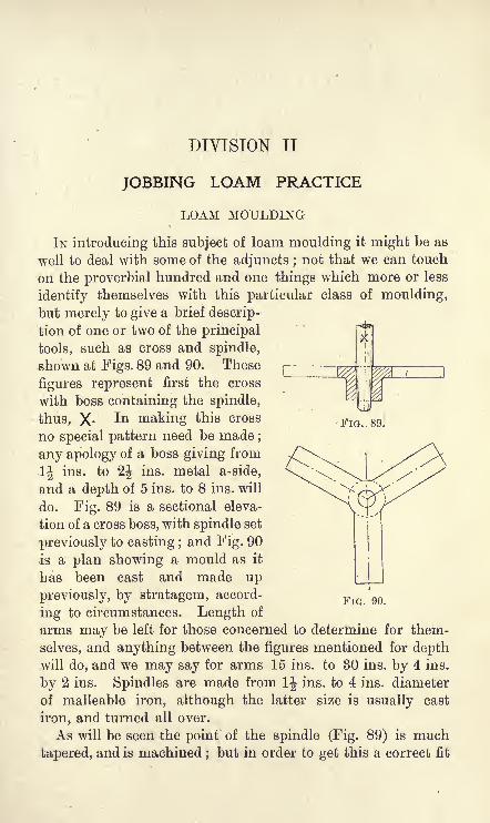
DIVISION II
L_
FIG. 89.
JOBBING LOAM PRACTICE
LOAM MOULDING
IN introducing this subject of loam moulding it might be as
well to deal with some of the adjuncts ;not that we can touch
on the proverbial hundred and one things which more or less
identify themselves with this particular class of moulding,but merely to give a brief descrip-
tion of one or two of the principal
tools, such as cross and spindle,
shown at Figs. 89 and 90. These
figures represent first the cross
with boss containing the spindle,
thus, X- In making this cross
no special pattern need be made ;
any apology of a boss giving from
1| ins. to 2j ins. metal a-side,
and a depth of 5 ins. to 8 ins. will
do. Fig. 89 is a sectional eleva-
tion of a cross boss, with spindle set
previously to casting ;and Fig. 90
is a plan showing a mould as it
has been cast and made up
previously, by stratagem, accord-
ing to circumstances. Length of
arms may be left for those concerned to determine for them-
selves, and anything between the figures mentioned for depthwill do, and we may say for arms 15 ins. to 30 ins. by 4 ins.
by 2 ins. Spindles are made from 1J ins. to 4 ins. diameter
of malleable iron, although the latter size is usually cast
iron, and turned all over.
As will be seen the point of the spindle (Fig. 89) is much
tapered, and is machined ; but in order to get this a correct fit
FIG. 90.

174 FACTS ON GENERAL FOUNDEY PRACTICE
it must be cast in the mould as we would a common mandrel,and for this purpose we have to paint or coat the point in
question, which will enable the spindle to leave the metal of
the boss easily after it has been cast and cooled in it. Manyare the patents we have seen tried, and some undoubtedlywere dealt with as secrets worth knowing ; but after all, nothingcan equal or surpass a judicious application of common tar.
Heat the spindle sufficiently to enable it to dry the tar after
dipping, then place in the mould as seen at Fig. 89, and cast
with comparatively dull metal; the spindle, if the heating has
not been overdone but has been sufficient, when cooled in the
boss will practically jump out of the casting, if only aided with
a little mechanical force. When placing the spindle thus tarred
in the mould, see to it that a small piece of the taper is outside
of the mould, which is"open sand," otherwise it will be found
that the straight part has been caught in the metal.
To the uninitiated on entering a foundry for the first time,
it must seem somewhat strange to see a moulder building
cope or core, or otherwise engaged in his vocation using his
naked hands for mixing and handling his loam as a brick-
layer does his mortar with a trowel. All conditions of weather
being alike for this, it is no light matter to break the ice andthaw it with a piece of warm scrap before proceeding to build,"rough," or
"skin," either cope or core. We do not say
that this is the only way of building, but certain it is wenever could with certainty create affinity, as known to loam
moulders, between loam and brick without rubbing the loamon the latter with the hands in a way practical moulders do.
The importance of having absolute affinity, and the necessityof securing freedom from holes or spaces of any kind caused
by the shrinkage of the loam joints, must always be borne in
mind. Gases will collect in any such spaces that remainand if simply skinned or covered over, will tend to escape
by the easiest way, which is through the face of cope, or core,
as the case may be. These weaknesses frequently go unde-
tected,- the blackwash in many cases being thoughtlessly
painted over such cracks, thus making the mould appear all
right on the surface. But, on the other hand, the neglected
space behind the smooth blackwashed surfaces forms a channel

LOAM MOULDING 175
for gases in such moulds, which are badly dressed previouslyto blackwashing, and the pressure of the metals not being
strong enough to keep these weak parts in check, nastyindentations on the castings are caused by the gases referred
to seeking to get out through the metal at the time of casting.
Through long practice and observation I have come to the
conclusion that all vein-like or groovey surfaces on loam
castings, as a rule, are due to the causes stated above. And,
may I add, the same effect is produced in dry-sand cast-
ings from intermittent soft ramming, or, perhaps irregulari-
ties from ramming too big courses ; especially is this the case
in large dry-sand core making. I have seen those defects as
mischievous as a dumb scab in making a bad casting, the
amount to be bored out not being sufficient to clean the
barrel of the casting.
Therefore, in the building of loam, work for affinity between
brick and loam, especially wherever such constitutes the face
of the mould. The necessity for this and for absolute densityof lojim joints, especially within half-brick of the face, give
ample reasons for using the hands as referred to in the
manipulating of loam and brick, in the art of loam moulding.It goes without saying that loam moulding as a branch of
the trade gives more scope for intelligence than does either
green-sand or dry-sand, because, as a rule, no pattern or
model is used in its completeness for the production of loam
castings. All loam work of cylindrical or spherical section,
is always best and cheapest, from every point of view, when"swept
"or
"streakled." 1 Some have the idea that loam is
always the costliest casting to produce. This is so far true,
but, in many cases, where the cost of castings is divided between
pattern-shop and foundry, much could be said in favour of
saving money in the pattern-shop, and spending a little morein the foundry, by making much that is done by sand in
loam. Still, where more than one is wanted, and wherever
practicable, and plant is suitable, make a pattern according to
the necessities of the case and mould in sand. It is also a
mistake to imagine that loam practice is confined to the
heaviest castings, either on account of cost or the limitations of
1 As previously stated.

176 FACTS ON GENEEAL FOUNDEY PEACTIOE
practice. Hence it is that some very small castings are both
of necessity and for economy made in loam. Loam may also
have to be resorted to, because of extraordinarily heavymetal, and when a superior job is wanted, as no material for
iron-moulding is so refractory as good loam. Again, no
mould of great importance would be as safe in sand as is
possible with loam ; consequently, such castings as the greatbell of Moscow, whose weight is given at 423,000 Ibs., and
whose thickest part is also given at 2*3 ins., circumference
near the bottom 67 feet, and height 21 ft., would undoubtedlybe a loam mould. No mould of any other material can be
kept so long in safety, and under normal conditions of
material, treatment and security from damp ;and with
neither frost nor an excessively moist atmosphere, no one
need be apprehensive of danger at the time of casting any job,
the time for which was unduly prolonged, while closing and
preparing for casting.
Although loam moulding, as has been said, gives greater
opportunities for intelligent foundry practice, it is by no
means the branch of moulding to which apprentices should
be first put, the reason being that nothing but sand can
cultivate that nicety of touch in handling the tools which
goes to make a good moulder. Also the control of sand
ramming, according to degrees of fluid-metal pressure, which
is so variable from the bottom of a mould upwards, and the
variation of force in the use of the rammer on each successive
course in the ramming up of a job to secure its safety from
scabbing or swelling at the time of casting, are, together with
the best texture of sand possible for venting, vital factors in the
production of sand-moulded castings but rarely met with
and indeed not necessarily thought of in loam moulding.
Obviously the principles of moulding are not taught with
the same force in loam as in the case of sand moulding,and specially is this tlie case with all classes of heavy green-sand work. Therefore, all apprentices should have a gooddeal of practice on the floor before being put to loam that
is to say, if the best training possible for making a first-class
jobbing moulder be aimed at. All after this are points of
detail which can only be mastered by long, thoughtful and

MOULDING A 36-IN. CYLINDER-LINER IN LOAM 177
observant practice. Now, the prime object of this division on
loam moulding is to assist those apprentices or sand moulders,who may be inclined for knowledge in this branch of the
trade. By a study of the foregoing, and the short series of
articles to follow, they may equip themselves for the future,
should they at any time be called upon to make a simple
piece of work in loam, but what follows is in no way intended
for men of experience in this class of work.
MOULDING A 36-IN. CYLINDER-LINER IN LOAM
A 36-in. cylinder-liner (Fig. 91) is one of the simplest jobs in
loam, and the following directions based on the writer's
practical experience as a moulder should, although somewhat
summarised, be quite sufficient to enable a sand-moulder (dry-
sand) of usual ability to make the job, even if he has no
experience at all in loam. There would be nothing intricate
about the job were it in sand, but the idea of going to a" bed
"and drawing-off the plant of the smallest of jobs
undoubtedly appears to be a difficult problem to many moulderswho have had no experience in this class of work.
Let the uninitiated try to remember that the first thing to
do is to"draw-off
"the job and all will come right. The
difference between drawing-off and using a pattern for the
same operation in the foundry is as that which belongs to
a mechanic in"drawing-off
"from a drawing as against
finishing the same article from a template.
Fig. 92 represents the bottom plate as drawn off before
proceeding to mould. For this figure, every straight line andcircumference is drawn to represent the job in every detail of
measurement which is thereon explained. The diameters of
core and cope are first put down that is to say, after the four
cardinal points (Fig. 9*2), which represent the handles, havebeen squared, and from which all other attachments are
calculated. A keen grasp of what is here stated gives the
key to all requirements in "drawing off," not only for this
job (Fig. 91), but for loam moulding as a whole.
From A to A (Fig. 92) is the centre hole for the spindle to pass
through, and perhaps a convenience for clamping the spindle-F.P. N

178 FACTS ON GENEEAL FOUNPEY PEACTICE
FIG. 91.
cross as well. BtoB gives diameter of core, i.e., 36 ins. C to Cshows thickness of metal on body of casting as 1 ins. D to D
is the facing belt at
both ends of the
liner casting. E to
E is clearance for
cope ring, and spacefor parting inclusive.
FtoFshows breadth
of cope ring,viz.9ins.
For the momentlet us view all parts
from the pattern
shop, such as sweepsand gauges for cylin-
der-liner (Fig. 91).
Fig. 93 is the bot-
tom bearing sweep,
Fig. 94 top cake
sweep for Fig. 97,
which is the top part
for this job. Figs.
9oA and 95B are the
cope and core gauges.
Fig. 96, A shows the
core board attached
to the spindle, and Bof the same figure
shows the cope board
in a similar position.
The above consti-
tutes all cost of pat-
tern making for this
liner casting, not a
very costly affair
indeed.
In Fig. 96, with the exception of the top cake (Fig. 97), and
for convenience of illustrating, there is shown in sectional
elevation all connected with the building of this liner casting as
FIG. 92.

MOULDING A 36-IN. CYLINDER-LINEE IN LOAM 179
seen at Fig. 91 ; and to those specially interested, doubtless, a
study in detail of Fig. 96 will be profitable. Again, in Fig. 96
is seen the cope completed with its sweep or streakle board
attached to shear irons Z), the board of course beingset with the gauge stick (Fig. 95A). C C C are the building
rings and are interspersed throughout according to fancysome would say every four courses of brick, others might say
eight ;it is all a matter of opinion, and, as a rule, does not
matter much, provided the top and bottom ones are placed right,
i.e., the bottom one for suitability of clamping, and the top one
previously to building the last course of brick.
On the left half sectional elevation (Fig. 96), is likewise seen
the core representing a
finished job in so far as
building, roughing, and
skinning are concerned.
The board A looks a
little slender and is sug-
gestive of weakness and
is thus apt to get out of
truth for finishing to size
correctly. Therefore, care
must be taken to prevent FlG 95Bthis by the most con-
veniently safe appliances at hand. E (Fig. 96) is one of
the cope handles, but a better view of these is seen in
Fig. 92. It will be noticed that the parting of the cope is
denoted by a heavy black line (K and H, Fig. 96).
Now the method of building is to make this core a fixture
to the bottom of plate F (Fig. 96) ; consequently after strikingthe parting, and when it becomes stiffened, we proceed to
set the board B and build the cope on the ring E. The
cope being built, "roughened" and "skinned" by sieved
loam, must have time to stiffen before removing it to geton with the core. This being done we now set up our
loam board A and proceed with the core, as seen on left-
hand half sectional elevation (Fig. 96). A careful look at
this figure, paying special attention to the core, should
afford all the information necessary to a practical man, and
N 2

180 FACTS ON GENEEAL FOUNDEY PEACTICE
further reference to it would be superfluous, except to say that
the three uppermost courses of brick should be tied with wire
to keep the whole from warping or twisting while drying in
the stove.
The practice of setting a loam board is to many a little
troublesome, and it goes without saying that the man whocannot do this has no claim to call himself a loam moulder.
Half Sedtional Elevatioof Core
Half Sectional ElevationoF Cope
FIG. 96.
Many good underhands, the bulk of whom were originally
sand moulders, have had but little, if any, chance to acquirethe ability to set a loam board which is always done bythe man responsible for the job. In view of what is stated
here we shall give an object lesson on this particular point,
and for this purpose we take the top cake plate of the cylinder
liner (Fig. 97). Taking this top cake as a study for the job
in question we will consider it as having half a dozen gates,
two of which may be used as risers;the rest will be clear

MOULDING A 3G-IN. CYLINDEft-LINEK IN LOAM 181
enough for all practical purposes. In the setting of this top cake
board (Fig. 97), and assuming it to be a good fit, it ought to
be kept clear a little, so as to make it enter easily when clos-
ing on its place shown in Fig. 96. In Fig. 97 the plate
is shown arranged in position with the cross C and its spindle,
thus, X. The shear iron D fixed to the spindle has the
streakle board (Fig. 94) attached to it and is held in position
by the aid of two or three bolts, as shown in the illustration.
Fig. 97 represents the gauge stick as setting and provingthe board (Fig. 94). It will be noticed, on the left of Fig. 97,
a piece of clay B has a brad fixed in it almost in touch with
gauge stick (Fig. 95A). Assuming our gauge to be on the
right on the
side oppositeto the brad, and
endways against
the nipple K,secure the brad
against movingin any way, then
come to the brad
with the board FlG 97
(Fig. 94), and the
brad being temporarily fixed, it is pressed gently in touch
with the gauge stick, as shown at Fig. 97, and if the board
be parallel to the plate and give a level surface, such a
setting of the board as here described must produce the best
workmanship possible. It frequently happens that a first
or second attempt is a failure, but with the board level
with the plate lift the gauge, hold it firm against the spindle
and as firm against the nipple K of the board, as shown at
Fig. 97, and while in this position bring the brad again in
touch with the other end of the gauge ;this done, tighten up
the board, remove the gauge, and bring the board round
again to pass by the front of the brad with an infinitesimal
clearance, and, if this be secured, the board is completely set,
and with the roughing of loam, and the finishing of this top
cake (Fig. 97), the moulding of the cylinder liner (Fig. 91)
is so far completed.

182 FACTS ON GENEEAL FOUNDRY PEACTICE
MOULDING A SLIDE YALYE CYLINDER IN LOAM
With this casting, as with all other loam work, our first
concern should be to see and study the drawing, and get it
well thought out before starting the job in any form whatever.
If working from a drawing, we must be careful about our
sizes, and should there be a full-sized drawing about, then
the right place for it is the foundry after the pattern shopis done with it. Formerly, in the best-organised districts,
all loam work was accompanied by full- sized drawings for
the foundry and all thicknesses in section painted black ;
this has now to a very great extent been displaced bythe " blue print," so that the moulder's capacity for reading
drawings requires to be of a more intelligent order in these
days than was the case or was necessary in the days of his
predecessors.
Assuming the"face
"(Fig. 98, A A A), which consists of
the steam ports and casing, is all one piece, and loam boards,
etc., are ready, we now proceed to cast the plant. But before
starting to do so, let us throw our mind's eye back on Fig. 92
for the guiding principle of this operation. This compre-hended, all else will assuredly follow. Having found our
greatest sectional plan (Fig. 99), which is through the
exhaust branch and centre of casing, we have got the key for"drawing down "
the bottom plate (Fig. 99). As will be
seen in studying this figure, there is first drawn down the
casting in full section, with the usual clearance of 1J ins. from
the casting, as shown in Fig. 99 and previously explained byFig. 92 ; then add other 9 ins. all round as shown, and squarecorners for convenience of handling, as also seen in Fig. 99,
and by putting the handles in their places, as shown with
dotted lines in same figure, the bottom plate is completedfor the cylinder (Fig. 98) in so far as the drawing down is
concerned.
Again, Fig. 99 is drawn down first with the intention of
showing the building rings, and the two snugs A A of this
figure are cast on for the purpose of binding the rings after

MOULDING A SLIDE VALVE CYLINDER IN LOAM 183
they have found their place on the building (Fig. 98, C C C).
Again, in Fig. 99, if after drawing the circles and straightlines which go to make the plan or section of this job, we also
FIG. 98.
FIG. 99
draw in clear lines what is dotted, then fill up snugs A A, the
bottom or base plate will be made as it should be. Thus we
illustrate building rings and bottom plate in Fig. 99 ; indeed,
this section in its outside measurement is the same for all
plates or rings cast for this job, from the base upwards

184 FACTS ON GENEEAL FOUNDEY PEACTICE
including the top cake, not necessarily shown. Therefore the
top cake is practically the same for measurement as the
bottom plate, but a larger hole in its centre will suit better, so
as to give 6 ins. a-side for "stamping" the main core at
the time of closing. Of course it must be daubed and gated
similarly to Fig. 97, i.e., if the metal drops through clear
space to the bottom of the mould.
The building plant for this cylinder thus briefly detailed
should, together with what instructions were given in con-
nection with Fig. 92, give the uninitiated in loam mould-
ing a fair amount of knowledge in how to proceed with
one of the most important parts of loam moulding.It will be noticed that in the selection of Fig. 98, we are
taking a step in advance of the cylinder liner, with which we
began, namely, Fig. 91, and as we some-
what fully stated the preliminaries of start-
ing to build loam work then, we consider
it unwise to go over the same ground
F again. Consequently a sectional elevation
is given in Fig. 98, which shows all
material in section, and presents to one's view a fair idea of
what it is we are trying to impart to others, with as little
repetition as possible. Hence the avoidance of cross, spindle,
boards, etc., in demonstrating the method of moulding a slide
valve cylinder in loam.
In the first place it will be noticed that the entire cope is
represented as being built fast to the bottom plate A (Fig. 98) ;
but before this can be done we had better form the bearing Bwith the sweep board (Fig. 100) and build the main core, other-
wise we should require to mould a "false bearing
" and makethe core apart from Fig. 98 altogether not a very commend-able way indeed. Therefore we take the sweep board (Fig. 100)
and form the bearing B (Fig. 98). This being done and
stiffened, we fix up the core board, not shown, get the barrel core
built and finished, and then afterwards removed to a convenient
place of safety. We next proceed to the building of the cope.
Building plate A and cope rings C are just the same, practic-
ally, as before stated. But, in building the bottom part of this
mould, build as dry as is compatible with efficiency, so that

MOULDING A SLIDE VALVE CYLINDEE IN LOAM 185
FIG. 101.
drying the mould at this part may not be unduly prolonged.Sufficient instructions for the building of the main core for the
cylinder (Fig. 98) will be found by reference to Fig. 96 (half-
sectional elevation A), adding an ordinary core iron with three
1-in. eyes cast in it as lifters, and a "bearing" formed, as
illustrated in Fig. 9ft, B.
The sectional elevation of Fig. 98, as will be seen, repre-sents the small cores all in position, with the mould ready to
receive the main core. The small cores give much matter to
enlarge upon, such as the making of irons for them, and the
materials of which they should be made, venting, and how
they should be dried, etc., all of
which are absolute essentials in
core making, but which it is not
advisable to deal with here.
However, a short description of
the method of placing the cores in
position, as illustrated at Fig. 98,
may be of advantage.* And, to
begin with, let it be observed that
D (Fig. 98) is a vertical bar to
which the cores are bolted. The
first core to be placed is the casing,
which had better be made quite
secure by bolting to D (Fig. 98)
as shown ; this done, we have a
good foundation for the rett. The bottom port is then
secured, and tested for clearance with gauge stick (Fig. 101),
so that no mistake may happen when the main core comes
to pass by it on its way to the bottom print B (Fig. 98)
when closing. The top port A is next placed in the same
or similar fashion. These ports being thoroughly secured
and tested in every way, and this part of the mould beinglikewise cleaned out, the exhaust core is put in, which
completes the most difficult part of coring a slide valve
cylinder of any dimensions. Fig. 102 shows the exhaust
core to be cut in two or three pieces (A and B), but
usually it is cut at A only. Of course this is only necessary* E E E are the bolts which secure the small cores to the bar Z>, Fig. 98.
FIG. 102.

186 FACTS ON GENEEAL FOUNDEY PRACTICE
when the cope is built all in one piece. The exhaust
core being fixed, and whether made with one or more joints
(as seen at A and B Fig. 102), to fake it matters not, it
ought to be chapleted top and bottom where jointing takes
place. If this be attended to, chaplets in such cases serve a
double purpose by keeping the core in its place and guaran-
teeing to a certain extent the safety of any of the faked partsfrom lifting or starting in any way at the time of pouring. FF(Fig. 98) are the vents secured and daubed with loam all round
the joints of the steam ports and exhaust core inside the
casing core. Great care must be taken to secure the metal
against getting into the vents, and when satisfied as to this,
thoroughly clear out all vents, then pack the space inside the
casing core A with suitable ashes, and insert tubes as shown
(Fig. 98, F F). This done, it will be seen that all vents are
collected to the casing and discharged collectively through the
two vent tubes F F (Fig. 98).
MOULDING A CYLINDER COVER IN LOAM
Whether such a cover as represented here (Fig. 103) is
cheapest and best, it matters not for our purpose. Large or
small, the principle is the same, except that the plates A and
FIG. 103.
B will require to be thickened in proportion as the diameters
increase, although those plates are seldom cast above 3 ins.
thick.
Figs. 104 and 105 are the loam boards, which explain them-
selves, but to draw off, cut, and finish these boards requires
one with some experience in loam work. It will be observed
that the section of metal is shown in Fig. 104, so as to assist

MOULDING A CYL1NDEE COYEE IN LOAM 187
in making it clearer to those who may not have experience
in this class of work, and before proceeding to use them in the
foundry they had better be proved by comparing the one board
with the other, and thereby prevent any possible mistake hap-
pening. The little nipple on the boards, thus, |||, are to steady
the size or gauge sticks when setting the boards, and should
be used on all loam moulding boards. In the sectional elevation
(Fig. 103) we have a fair representation of the mould in its
completeness preparatory to making it ready for pouring.
A is the bottom plate, C is the spindle-hole (rammed up with
sand), which may be any size compatible with safety for the
bottom of the casting. The fixing of the spindle with its cross
is not shown, but must be taken for granted to be as usual,
FIG. 105.
while the hole should be larger than shown at Fig. 103, A, so
that the clamping of the cross may be easily got at if need be.
The top plate B of this figure shows two pouring gates E E,and it must also have a 3-in. or 4-in. hole in the centre for
working the spindle. Sometimes these covers are gatedround the circle, and " flowed
"by risers in the centre.
The latter way of pouring, however, in my opinion, creates
unnecessary work, and I never knew of anything going wrong
by gating in the centre instead.
This would be quite a plain job but for the stuffing-box
flange, which necessitates the use of a" cake
"in halves FF
(Fig. 103). This does not present any unusual difficulties, and
of course there are various ways of moulding it ; but what-
ever way we choose, the tongue K of the loam board (Fig. 104),
which forms the flange of the stuffing-box of this cover, had
better be detachable.
In commencing to build, the spindle is put into position as
shown at Figs. 96 and 97, and the first course of brick is
merely bedded down on loam, leaving all joints except the
outside course to be packed with dry ashes, as illustrated at

188 FACTS ON GENEEAL FOUNDEY PEACTICE
G, Fig. 103. In the building of loam moulding some have a
strong inclination for all parts next the casting to be done
with loam brick;others are not so particular, hard or soft all
seem the same to them. The latter, in my opinion, is by far
the better practice for more reasons than one, and specially is
it so when surfaces or projections are considered. But for
vertical parts such as illustrated by cylinder and liner (that is
to say, the open parts), hard brick becomes the indispensable
article of construction. So, then, the first course of brick
being laid for this cover (Fig. 103), and the ashes packedbetween them, our next course should be loam brick, at least
on what is to form the face of the casting, which is the flange
of the stuffing box in this particular case.
In forming or sweeping this flange, we should endeavour to
strike only the bottom and sides, which only need to be roughedand stiffened. With the flange thus prepared we now place on
top of it, the rough dried cake of loam in halves (Fig. 103, F),
and with sufficient clearance for the tongue K of the board
(Fig. 104), to get working, and at the same time making it
good for skinning as well. When building this class of work we
must keep down as far as possible wet joints, both for dryingand venting purposes. In Figs. 103 and 112 the zig-zag joints
in their structure, show in a way the ashes placed between
the joints of bricks for the double purpose of drying and
venting. These covers and similar work are usually cast
without pitting, as known to loam moulders. Figs. 103 and
112, K, represent two bands of hoop iron encircling these
copes, just as malleable hoops would a barrel, and when
looped at both ends with annealed wire and fastened firmly,
no danger from pressure under normal conditions at the time
of casting is possible.
COEES AND COEE IEONS FOE A SLIDE VALYE CYLINDER
When describing, in the section on "Moulding a Slide
Valve C}7linder in Loam," the method of placing the cores,
only a brief reference was made to the materials used and the
methods of making these cores and core irons. In order,
therefore, to preserve the continuity of this subject, the making

COEES, ETC., FOE A SLIDE VALVE CYLINDEE 189
of core irons and cores for such a cylinder, will be considered
more fully, the details given being all that should be requiredfor this particular method of moulding the cylinder in
question. It must be understood that what is given here is
intended to fit into the existing circumstances of an ordinary
jobbing moulding shop, and where specialisation in this
sort of work exists other methods may be used, and prove
FIG. 106. FIG. 107.
superior practice. The core-boxes are only shown in sectional
view along with the cores, and thus have not the completeness
desirable, but there should be enough in the accompanyingfigures to show how best they may be made in view both of
good practice and economy, especially as regards economy in
conjunction with the pattern shop.In Fig. 106 we have the steam port core-box in section along
with its core iron B. Fig. 107 shows the plan of port core iron,
and the dots interspersed indicate malleable irons, thus ribbing
FIG. 108. FIG. 109.
the core iron as shown at B, Fig. 106. Fig. 108 is the sweepwith a check on its right-hand side to keep it in its place while
working along the edge A of this core-box, thus forming the
hollow side of the steam port core-box, and, the section of core-
box being shown, no other information is necessary for makingit. Fig. 109 shows lightening core-box with plug hole C for
venting and fettling purposes. The simplest way of making

190 FACTS ON GENERAL FOTJNDKY PEACTICE
this box is to cut two pieces in section and line up this to the
proper length, and with a flat board screwed on as seen in
section (Fig. 109) we have a complete core-box with very little
cost. The plug-holes (Fig. 109, C) had better be carefullymarked on the mould and core, and the vent ways made goodand clear for the escape of gases. By this it will be seen that
the plug-vent cores C are made separate ;this being so, on the
placing of these lightening cores, the plugs find their places in
connecting themselves by
provision being made for
vent-tube arrangements
through the mould. This
method is easy, simple, and
safe, and gives means for
the rapid exit of gases from
the lightening cores, as
seen in sectional elevation
(Fig. 98). These vents
are indispensable for
fettling purposes as well.
Fig. 110, shows a
sectional plan of exhaust
core and core iron, and
represents the handiest
way of making this core-
box and core, minusthe round branch, which
may be made from an
ordinary"stripping
"
piece or ordinary roundcore-box of the required
diameter. The dots again in Fig. 110 represent malleableirons cast in the frame, which is a single iron, stamped fromthe impression of the core-box. These malleable irons shouldbe zig-zagged, for by doing so we secure nice space for ventingand bonding the core. Also, these malleable irons must befixed in the core-iron mould previously to casting it, with in.
clearance a-side, according to ordinary core-iron practice.Further, we must not forget to examine our conditions of
FIG. no.
FIG. ill.

MOULDING A PISTON IN LOAM 191
moulding a cylinder with this core, so that we shall knowwhether to make it in one or more parts as previously
explained in Fig. 102.
In considering the section of the casing core in the box
(Fig. Ill) it must be seen at a glance that this core is madein its box conveniently. Sometimes it is built, and, instead
of being shown with one core iron, as seen at Fig. Ill, not
less than four, if illustrated, would be seen when built vertic-
ally ; and when other things are equal vertical building of
casing cores is, in our opinion, the best, no matter from what
point of view we take it.
But, in Fig. 98, the face is represented as being done with
a cake, and this being moulded true to the parting of same, we
s c
Vent
FIG. 112.
bolt casing core to face plate and lower both together into their
places, as seen at Fig. 98, arrangements for which must be
made at time of building the cope. Needless to say, no patterns
are required for making these core irons except for the steam
port (Fig. 107), and which ought to be made a little less in
section to admit of loam for clearance of core-iron casting, or,
according to usual core-iron practice, as previously stated.
MOULDING A PISTON IN LOAM
For the sake of simplifying matters we shall keep very
much on the lines of the cylinder cover (Fig. 103) with this
piston (Fig. 112), and the better the former job is understood,
the easier will the moulding of a piston in loam be made.
Moulding plates, top and bottom (Fig. 112, A and B), of this
job are practically the same as the cylinder cover (Fig. 103),

192 FACTS ON GENEEAL FOUNDRY PRACTICE
less the holes for venting and fettling, common to all hollow
piston castings. The pattern pieces of this job are here
given in detail. Fig. 113 is the top board for the top cake;
Fig. 114 represents both the bottom of the mould and the
thickness board for putting sand to the thickness of the metal
on the face of the mould, thus preparing it for making the
cores as seen on the plan, Fig. 117. In Fig. 114 the hatched
lines indicate thickness of metal which can be cut away and
used as the thickness board after the bottom of the mould is
finished, if thought advisable, but the better way is to make a
board for thickness purposes alone. Fig. 115 is the plug-hole
core-box, which serves the purpose of venting and fettling out
these cores. These plugs are usually fixed on the cores at the
time of dressing, preparatory to blackwashing. So much for
FIG. 113. FIG. 114. FIG. 115.
details. We pass on to say that, after the spindle has been fixed
and loam board (Fig. 114) set for moulding, there is nothing very
special for consideration but venting. In regard to this point,
the first course of brick should be ash jointed, as shown in
Figs. 108 and 112, but in the next course, which is next the
face of the streakle board (Fig. 114) and if the vent-plug cores
must be in the bottom (the most undesirable side by far for the
moulder), a circle of ashes as shown in Fig. 112, C, becomes
imperative, so that when coring the job the face of the mould
may be tapped anywhere down through those four cores, as
shown at section (Fig. 112), and thus catch the plug-vents at
any point. This circle vent is led out by branches three or
four in number, or more if required (see vent, Fig. 112).
Wherever venting from the bottom is imperative, an extra
course of bricks with ash joints becomes advisable, thus
facilitating the venting of gases in these piston-cores.
As is well known, much danger is at all times connected

MOULDING A PISTON IN LOAM 193
with the casting of hollow-box section pistons, and of coursethe greatest trouble arises from the cores. Consequently, wecannot be too careful in all that pertains thereto first, as to thematerial with which the cores are made ; second, the necessityof proper baking or drying. These cores
being enshrouded in metal and no escape for
the gases but by the plug-holes, it becomes
imperative to burn as much of the vegetablematter out of the cores as possible, and as is
compatible with their safety, so that the
accumulation of gases from these cores is brought to theminimum. As has been said, there is but one way of escapein general practice for the gases from the cores, viz., throughthe individual plug-holes. There is no reason why this shouldbe so, as by a little ingenuity all cores can be made inter-
communicable, and by doing so, should any mistake occur
FIG. 116.
FIG. 117. FIG. 118.
at time of casting by reason of one or more plug-vents
becoming choked, the gases from such a core or cores would
escape through the cores right and left of the one whose vent
had become choked. Clearly we see in such an arrangementas this that the danger of losing the piston becomes minimised,for undoubtedly many a good hollow piston casting has been
lost by "individual-venting," for which collective-venting can
be easily substituted.
F.P. o

194 FACTS ON GENEEAL FOUNDKY PEAOTICE
Fig. 117 shows the position of the cores as they are placed in
the mould when closing, and Fig. 118 is a view of the core
irons as they may be cast. These core irons are drawn off
on the bed by square and compasses, and are formed by
"stamping" according to the judgment of the moulder.
However, the purpose of Fig. 117 is to show the cores in
position, and it also serves to show the plan of the top cake,
which in some cases is a duplicate of the view we have here,
plus whatever more may be required for posting on joints.
Make the holes for vents, as seen in Fig. 117, large enough to
admit the plug-cores to pass up into the prints, as seen at G,
Fig. 112, so thatthe securing of the vents by telescoping tubes
into the cores, or otherwise if thought better, may be the safer
effected. The same way of telescoping vent tubes must be
religiously attended to when plugs are down through the
bottom of casting, as seen on right hand of Fig. 112, A.
Three or four gates H H on the boss are quite sufficient for
running, and four flow gates for risers S S (Fig. 112) should
suffice for castings of this size, and up to a considerably larger
diameter.
LOAM MOULDING IN BOXES OR CASINGS
The item of "pitting" with loam moulding is always of
serious concern in the cost of production, and but for this
much that is done in sand would be made in loam. Although,in open floor work, as shown with covers and pistons and such
like, moulds are made, as seen in Figs. 103 and 112, where
hooping K is all that is necessary for security of pouring, yet
these are not the only exceptions to the rule of pitting, and its
consequent cost in loam-moulding. Much work is also done
by faking with plates and daubers, both for vertical and
horizontal moulding, especially as it is practised in the loam"specials
"departments of pipe foundries.
As has been previously mentioned, loam work is frequently
resorted to because of the want of plant and pattern, but
where the former may be at hand without the latter, there is
no reason why we should not use the plant and substitute
loam-boards for a pattern, such as has been advanced for
cylinder-covers and pistons in thia chapter on Loam Moulding.

LOAM MOULDING IN BOXES OR CASINGS 195
Therefore, in connection with this method of working we
show in Fig. 119 the same piston as Fig. 112, moulded in a
box in loam. The sectional elevation of this (Fig. 119) shows
everything in position, and ready for the metal. A is the
spindle cross, but, before placing this in position, our first
duty is to ram a course of sand in the bottom of the box
as shown. This done, we fix the cross, get the spindle
adjusted, set our loam board and build on one course of
loam brick as seen, and so on, according to our experience
of this sort of work, all of which has been explained in con-
nection with Fig. 112. B is the moulding-box, C is the top
cake, D, D, D are risers and pouring basins, and E, E are
FIG. 119.
the clamps for binding the job ; G is the core, H H are short
pieces of iron by which the cores are suspended to the topcake, a method in most cases commendable, and which does
away with chaplets for carrying cores on the bottom of mould.
S S are vent tubes.
In some cases we have used a flask for covering such a jobas seen at Fig. 119, but the trouble of catching all vents clear
of the bars of the boxes in question makes in most cases the
top cake C (Fig. 119) the best and cheapest in the end.
This short summary of making a piston in loam by using a
box as a casing shows the advantage of this method when
compared with that illustrated by Fig. 112. By such practicethe building gives less work, hooping with iron or pitting is
done away with, and where a repeat is wanted we have an
o 2

196 FACTS ON GENERAL FOUNDEY PRACTICE
approximate saving of 75 per cent, of the cost in buildingthe bottom part of this piston mould. Besides, this as a
mould is much easier slung and handled in every way ; manyadvantages are thus gained when moulding loam in an ordinary
moulding-box, as illustrated at Fig. 119. For reasons which
may be obvious the vents are not shown secured, but are
intended to be done in the usual way by first securing the
Sand
FIG. 120.
space with "waste," then afterwards ramming all space, as
seen at H H (Fig. 119), with rock-sand.
MOULDING A 20-IN. LOCO. BOILER-FRONT CRESS-BLOCKIN LOAM.
In this our second example of moulding loam work in a
box, we have an article of great importance for the boiler-
maker, for, just as his cress is free from disfiguration of scab
or swelling, so in like manner will the contour and finish of
the face of his job be perfect. Looking at the plan and section

MOULDING A BOILER-FKONT CEESS-BLOCK IN LOAM 197
of this boiler-front cress (Figs. 120 and 121), it will at once
be seen that for such a plain casting the cost of pattern must
be considerable, i.e., when it has all to be put onto one casting,
as is very frequently the case, especially in the smaller loco,
building shops of the country. But, apart from this altogether,
a loam casting, we should think, is imperative, because the
exactitude of curve and surface for the boilermaker to cress
from cannot be equalled with either green-sand or dry-sand
castings the former being bad practice under the most
favourable circumstances imaginable. From an economical
point of view this job, weighing, say, 16 cwts., is pre-eminentlya desirable one for making in loam, not only for reduction in
cost, but in the saving of a pattern, and it is no exaggera-tion to say that for all parties and purposes loam moulding
"V ....M>. - ^9.a/7Q. VI ^.. ..,,
^.C,W:Jv^;i^tZ3
FIG. 121.
for this class of work is the ideal way for economy, and
good workmanship. In short, this casting ought to be
produced for about half of the money required to meet
the cost of a pattern, and were two moulded instead of one (not
necessarily of the same dimensions), the cost again becomes
considerably reduced, thus showing a case in which a loam
casting becomes the cheapest in the wages book of the foundryand pattern shop as well.
In viewing Fig. 121 it will be observed that everythingis shown in section as the job stands rammed up, before
parting it for finishing. Let it be taken as matter of fact
that the bottom-box is on its back ready for starting. This
admitted, our first move is to get the spindle (not shown)fixed up for proceeding to build, and afterwards ram a course
of sand A as the foundation of the job. This sand beingrammed abnormally hard and of uniform thickness, we

198 FACTS ON GENERAL FOUNDRY PRACTICE
bed in two straight edges, not shown, for the purpose of
levelling the flat face of the mould beyond the reach of the area
swept by the circle Fig. 122, at the round end of the casting.
The whole surface being formed by the aid of these straight-
edges and sweeps (Figs. 122 and 123), we next build round
FIG. 122. FIG. 123.
the circle end (Fig. 120), and form this end of the parting
complete. At this point, bottom and circle end being now
swept, these must have time to stiffen or dry, to admit
of the parts shown in Fig. 124, right and left, along with
Fig. 125, being placed into position (Fig. 120), which completesall outside measurements of the casting.
It will be noticed that those two flat sticks
(Fig. 124, which it will be rec.ognis.ed serves to
illustrate both) are placed to determine outside
size of casting, and also serve as guides or rails
whereon the sweeps (Figs. 122 and 123) move
along when sweeping the bottom of mould which
forms the outside or face of casting. Sweep
(Fig. 122) being used for faking round the corners
where the other sweeps cannot reach, the joint
guides, right and left (Fig. 124), are held in
position by a screw nail at the circle end as
shown in Fig. 120, and of course weights are
applied at the opposite end for a similar purpose.Those details bring us to the point of finishing
off the entire face of the mould and parting,FIG. 124. . . . ... j
inclusive of everything pertaining to the dragor bottom of the casting.
Before proceeding further, we must first satisfy ourselves
that the drying of the mould is firm and rigid ; afterwards
put thickness of metal on with sand by the aid of the
sweeps (Figs. 122 and 123), in a style similar to the formation
of the bottom of the mould;these two sweeps being used to

USE OF ASHES AND DKY-SAND IN LOAM MOULDING 199
form the face of the mould, the thickness of metal is formed
by reducing them to the dotted lines. A reference at this
point to Fig. 121 shows in section the thickness of metal formed
by sand. Having now got our
thickness formed and slightly coated
with parting sand, our makeshift
pattern is complete. Next, put in
sand for hangers or gagers, then FIG. 125.
put on the top part or flask and
ram up in the usual way, thus showing the job as it stands at
Fig. 121.
Briefly, we now proceed to part the job and finish. The
thickness sand C (Fig. 121) being removed, the design, as
shown here also, can easily be " faked"
without the aid of
core-boxes by the moulder, and, if need be, without any aid
from the pattern shop at all.
THE USE OF ASHES AND DEY-SAND IN LOAM MOULDING.
There are men who are good and successful moulders who do
riot in any way recognise the utility of using dry ashes in
building loam work. Such men stoutly advocate that to apply
dry ashes, as has been indicated in this section, tends to
hinder rather than help the drying of such work in loam.
They assert that the steam generated from the adjacent wet
loam joints of a mould condenses amongst the ashes and so
retards the drying. When, however, the mould becomes
thoroughly warm throughout, there is little likelihood of anylocal condensation of moisture among the ashes in any
part of the mould, and the speed of drying then depends
upon the temperature to which the mould is brought in the
stove.
It thus becomes a question of quantity, and, as an example,
suppose that we have two brick structures, each measuring
1 cubic yard one being solidly built of brick and loam
throughout, and the other with loam joints on its outside
courses only, the inside joints being made with ashes. Now,
in the solidly built cube referred to, we shall have approxi-
mately double the loam used when compared with the second

200 FACTS ON GENERAL FOUNDRY PRACTICE
cube, whose inside joints are all made with dry-ashes. It
thus seems paradoxical for anyone to assert that in the dryingof those two cubes the one containing the greatest percentageof water, from its wet loam joints throughout, should be the
one to dry first, as against the one with its dry ash joints in
the centre.
However, such is held to be the case by many good and
successful men in the foundry, and it is quite in keeping with"cores feeding castings,"
" down pressure on the tops of cores
when metal passes over them," etc., etc. But, to keep moreto the question of materials for building loam-work, we are
specially brought face to face with these two dry materials, viz.,
ashes and dry-sand, which are largely used by some when
building integral parts of loam moulding ; others do not
recognise them at all. This we think a mistake, for reasons
previously given. Each of these, i.e., dry-sand and ashes, have
their own particular function to perform in the foundry ; but
in this case it is for the purpose of venting and drying. Sand is
most economical both in its use for building and that of empty-
ing or taking a casting out of the pit, or from elsewhere, after
it has been cast, because ashes, on the other hand, become con-
taminated with the debris of the mould, and so add considerablyto the cost of lifting, after having cast, this class of castings a
point worthy of serious consideration. Therefore, as a result,
ashes, in the author's opinion, should be used with discretion
for building loam-work, unless venting in such work as we have
described is a necessity ;all the same, where venting and drying
are equally necessitous use ashes as suggested. Again, as to
which is best and without considering the economical side of
the question at all, we unhesitatingly say dry-ashes, since theyare practically unaltered in volume by the absorption of water.
The proportion of shrinkage produceable by watering dry-sandto a moist consistency for moulding is a point in many ways
worthy of the serious consideration of moulders. Dry-sandmust always be used with discrimination. When dampness,
or, worse still, water is encountered at the bottom of a hole
that is being dug in the floor of a foundry, it is a mistake to
get out the wet sand quickly and hurriedly replace it by dry -
sand without having first stopped the entry of the water.

USE OF ASHES AND BEY-SAND IN LOAM MOULDING 201
Serious losses often happen in this way, as many moulders
know from experience, since the water ultimately soaks into
the dry-sand causing it to contract, and, assuming a mould to
be rammed up under such unfavourable conditions, the pressureof the metal at the bottom of the mould and at the time of
casting tells its own tale by the casting showing ugly strains
on the bottom when lifted, i.e., if it has not finished itself
previously by making for the roof at the time of pouring.This is the case with all earthy substances that are abnormally
dry, and nothing but water or liquid of some kind will, in
the first place, bring the greatest density. And, as a matter
of fact, dry-sand in a foundry can never be reckoned as
a fixed quantity, as absorption of moisture will in some
degree cause it to shrink or contract.
On the other hand, absolutely dry-ashes is the friend of the
moulder in damp pits and similar places. It is commonpractice, when dampness may be considered dangerous, to
seek to form a channel by which it becomes located, andif possible connected to some way of escape. But if an
ooze of water, such as is common to most foundries when
working at abnormal depths in the floor, is likely to be a little
troublesome, localise such as much as possible by forming a
channel or hole. Get to know the volume of water collected
in such space within a given time, and knowing the numberof days or hours you have for ramming the job and casting it,
you thus arrive at the size which the hole should be dug to
contain the dry ashes, which absorbs the water practically,bulk for bulk, before it can get dangerously near the mouldat all. Truly this material, dry-ashes, has many functions to
perform in the foundry first, in its capability of venting;
second, in facilitating shrinkage : and third, in absorbingabnormal damp, the foe of the foundry, which has done so
much mischief both to life and property wheresoever the
art of founding is known.
Lastly, and most important of all, if a mould is known to
be in a critical state from damp, make sure and dig a hole or
trench, as the case may be, adjacent to the affected area of
the mould, and at a depth sufficiently below the deepest partof it. Thereafter form a coke bed of sufficient section so as

202 FACTS ON GENERAL FOUNDRY PRACTICE.
to enable the water in the damp area of the mould to percolate
into it ;and the water thus secured will flow into a temporary
well or "sump" prepared in the process of ramming up the
trench. This method of dealing with damp floors has, in the
experience of the Author, saved what otherwise might have
meant incalculable loss.

DIVISION III
MOULDING AND CASTING THE FINER METALS
STARTING A SMALL BRASS FOUNDRY
MACHINERY iron castings in general are accompanied by a
greater or less percentage of brass castings, and these, accord-
ing to location, are not always easily and cheaply got.
Therefore convenience and economy is generally best secured
by working a small brass foundry, or department, as an
adjunct to an iron foundry situated in a country district.
Besides, what suits in a general way the circumstances and
situation referred to, will, without doubt, adapt itself in a quiet
and unpretentious way to the jobbing work of a brass foundry in
city life as well. If there be not much capital to account for,
the chances are that such small brass foundries will give a
better return for whatever money may be invested, with workat a fair remuneration, than many of the more up-to-datefoundries. In short, there has always been, and will very
likely continue to be, a place in mechanics for the jobbingbrass founder. Hence, our purpose for the present is to deal
more particularly with country districts where the local iron
founder has to do a certain amount of brass casting, perhaps,in the smithy forge with an improvised fire or furnace, with
the result that the opportunities for doing business to profit
is neither practised nor developed.On the lines suggested here, the outlay necessary to start a
jobbing shop, or add a brass department to an already existing
foundry, is not very great. All that is required is a suitable
building of brick or iron, or a corner in the iron foundry, in
which to put up a couple of good crucible furnaces, as illus-
trated in Figs. 126 and 127, a space for the accommodation of
sand and fuel, of which only a few tons are needed, a few boxes,
and a tub such as is illustrated in Fig. 128. Besides these

204 FACTS ON GENERAL FOUNDRY PRACTICE
there is only the metal and a few other accessories to be
considered before the equipment of a small brass foundry can
be said to be, nominally, complete. As to the floor 'space
necessary, a shop 14 ft. square will be sufficiently large as a
start for the work common to local jobbings. It is desirable in
arranging for this to select a spot contiguous to a chimney,as otherwise an improvised stack about 20 ft. high in brick or
iron will be required. With regard to the plant mentioned
above (the question of forced blast we do not entertain)
the sketches of
B B the furnaces (Figs.
126 and 127) will
be sufficient to
afford all the in-
formation needed
by a practical
builder. It maybe added, however,
that the interior of
the furnaces, and
the flues immedi-
ately leading into
the chimney should
be of specially
selected firebrick.
As to the moulding-tub (Fig. 128), the
sectional dimen-
sions are given : the length will be determined, of course, bythe space available. Coming to the moulding-boxes, their size
will depend on the class of work intended to be done. How-
ever, three favourite sizes can be recommended for ordinary
work, say, 10 ins. by 10 ins. by 4 ins.; 18 ins. by 12 ins. by5 ins.; and 15 ins. by 11 ins. by 5 ins. The constructional
details are described in"Starting a Small Iron Foundry
"(p. 1).
The foregoing is but a rough synopsis of location, building, and
materials required for a small brass foundry.
Furnaces. It is a truism to say that the furnaces for melt-
ing brass are in many cases of a very primitive type; some of
FIG. 126.

STARTING A SMALL BEASS FOUNDRY 205
them are mere holes in the ground. The furnaces shown in
the accompanying sketches, while not of the most up-to-date
pattern, are, if built according to instructions, quite satisfac-
tory, both as to time and economy of melting, under normal
conditions of working. During recent years oil-fired furnaces
have come into vogue, and some brass founders consider them
suitable for smaller foundries. Before, however, they can
be recommended unreservedly, the would-be brass founder
^^^
FIG. 127.
should consider well the relative facilities in his district for
obtaining the fuels required for the competing systems, and if
forced draught be imperative the relative cost of this and the
chimney has got to be considered.
Figs. 126 and 127 represent the fires in section, and show the
relative positions of the fire-bars, flues, and covers, with the
crucibles in place. The dimensions given are 3 ft. 6 ins. deepfrom the cover to the fire-box, each furnace being 18 ins. squareShould there be reason to suppose that the fires may at anytime be used for steel melting, 4 ins. or 5 ins. more space around

206 FACTS ON GENERAL FOUNDRY PRACTICE
the crucible should be provided for in order to admit of
gannister being rammed round the furnace, with a view of
facilitating economical repairs. Personally, we favour the
use of the gannister lining even in a furnace intended for brass.
A good deal of time and money is wasted in pulling out fire-
brick linings for repairs, when the process of ramming the" hole
"with gannister 4 ins. thick would obviate much of the
loss arising from frequent rebuilding. Bound the top of the
bricks a coping of cast iron A (Figs. 126 and 127), which should
be 2 ins. thick, is imperative. This coping secures everything
and provides a top to the furnace suitable for the reception of
the covers B (Figs. 126 and 127), which ought to be level with
the floor. The covers may. . have cast - iron frames, with
clay- tile centres and bow
ff handles, such as are used for
moulding-boxes ; or they maybe of 4-in. fire-clay tiles,
bonded with wrought iron.
24-'- 4[ The bearers of the fire-bars Cshould be built into the walls
of the furnace about 3 ft. or
4 ft. above the level of the
furnace pit floor. The walls should be 18 ins. thick and a
similar space between each furnace, the ashpit being formed
below (see Figs. 126 and 127).
In laying out the cellar or ashpit, plenty of room should be
allowed ; there is nothing more annoying than to find, after
the furnaces have been built, that there is not enough room in
the ashpit for working. Fig. 126, D, shows the vent holes which
connect with the general flue, not illustrated. The advantageof these is not commensurate with the expense involved, and
they are on that account scarcely commendable. Again, at
the same figure E E represent the other vents or flues which
lead direct to the chimney at the top under the cover B (Figs.
126 and 127). These vent holes are usually regulated by meansof a brick which retards or accelerates melting of the metal,
so that the pot is ready for pouring at the proper time. The
accessory equipment of a furnace consists of crucible tongs,

STAETING A SMALL BEASS FOUNDEY 207
flat tongs, a poker, a crucible charger, a shovel, and a riddle.
These are all too well known to admit of space being taken upwith illustrations or figures of any kind
; and here let it be
said, that after pouring, a new pot should be put back into
the furnace to cool down slowly with the fire, for thereby the
life of the crucible will be prolonged.
Wastage in Melting. The wastage in melting brass is
always a matter calling for careful attention. It is necessary
to avoid melting with too great heat in order to obviate"burning
"the metal, which is a common cause of waste in
brass foundries, and more especially is this the case where the
reverberatory furnace is not in use. Some brass founders use
ordinary"splint
"or forge coal, which practice was common
enough in the author's early experience ;but of recent year
cheap cokes have come into the market, and nowadays it is
more economical and in every way better to use these. It is
not good practice to melt brass with good foundry coke,
because its calorific value is higher than that required for the
metal, and its use is needlessly sore on the crucible, to say
nothing of the fact that there is always a possible chance of
unnecessary loss of spelter due to too high a temperature.Brass is an alloy of copper and zinc (spelter) to which vary-
ing quantities of tin and lead are sometimes added. Coppermelts at a temperature approaching 1,100 C., which is
more than double that of the melting points of either zinc,
tin or lead. The temperature required in melting copper is,
however, some two or three hundred degrees lower than that
necessary in melting iron, and it is thus obvious that to
use foundry coke for melting brass means employing an
abnormally high temperature, and hence unnecessary waste.
In addition to wastage in melting, there is also wastage of
metal in pouring. When the crucible is taken from the furnace,
the skimming or cleaning of the metal should be done at the
"skimmings box," in which all refuse from the working of
the pots is collected and afterwards dealt with. It is here that
experience manifests itself in preparing the metal for pouringthe moulds, as much spelter may be unduly wasted by
unnecessary puddling and skimming before casting. Also
after pouring, whatever sand may have been in touch with

208 FACTS ON GENERAL FOUNDRY PRACTICE
a possible splutter should be fine riddled or sieved preparatoryto hand washing, a process common in small jobbing shops.
These points of economy mean money in proportion as theyare practised, thus keeping the wastage of metal in a brass
foundryproducing jobbing castings, at the lowest possible point.
Moulding. One of the greatest difficulties an iron moulder
finds when he starts upon brass work, is connected with
the gates, the position of which on the casting does not follow
the rule for iron founding, either in location or volume.
Brass oxidises more rapidly than iron, and when oxide is
formed in the filling of a mould, it has a knack of finding its
way into some portion of the casting where it is altogether out
of place, and of causing a bad casting. Consequently, it
follows that the mould must be poured rapidly, and in order
to ensure this, the brass must be run about three times
quicker than iron. By this we see that the proper position of
the casting has much to do with the successful working of a
brass foundry, and this is particularly the case with heavybrass. It does not require much imagination to see that
quick pouring will necessitate good and quick venting, and to
vent as one would do for iron, would involve risk of accident or
mishap, because iron being poured so much slower than brass
allows the vents to burn off their accumulating gases as fast
as the mould is filled. The result of this is, that the gases in
many cases are practically expelled before the mould is filled,
whereas with brass it not infrequently happens that the
mould is full before the vents are ignited. Practical moulders
know that a "blow" and "sputter" may accompany the
pouring of iron, and with a good deal of commotion too, and
yet the casting may turn out all right because the gases get
away, as a rule, while this commotion is going on, and there-
after the metal falls back quietly into the mould. But whenthe same kind of behaviour happens with brass, it is pretty
safe to prophecy that the casting will not be a good one. Onthe other hand, brass, in spite of the fact that its surface
when in the crucible is heavily laden with oxide, will penetratea finer design and thinner section of metal than cast iron,
which, under normal conditions of fluidity, seldom shows more
than the oxide line clinging to the ladle previously to pouring.

STARTING A SMALL BRASS FOUNDRY 209
Temperatures. There is no doubt that temperature is a
most important factor in the production of sound and homo-
geneous brass castings, as indeed it is in all processes in the
different branches of founding. Although all metals in their
behaviour during the fluid state have a strong relationship to
one another, each has its own peculiar characteristic. The
temperature at which brass may be poured with satisfactory
results in various classes of work cannot be determined, except
by that experience which is born of long practice. In this
matter the general conditions must be considered, such as
mixture of metal, condition of mould, and the volume of
metal in section, etc., all of which are factors in determiningat what temperature to pour.
-Again, as to the constituents of brass, it should be pointedout that these have their own particular melting points, andit is at times difficult to decide whether the component partsof the alloys are strictly correct. The melting point of copperis 1083 C. ;
zinc is 420 C. ; lead, which is not often used
and alloys badly with other metals, is 327 C. ; andlower than all, tin melts at 232 C. These differences are
enough to create difficulties in themselves, and when wecome to the specific gravities we find similar divergencies ;
copper is approximately given as 8*96, zinc 7*10, tin 7'29, andlead 11 '45. Lead does not alloy with the copper and zinc in
brass, but is present in the casting in the form of globules or
streaks. This property of lead combined with its low melting
point and high density causes it to have a great tendency to
segregate, i.e., to be unevenly distributed through the casting.It is a matter for no surprise, therefore, that even the most
experienced meet with disappointments when the relative
parts of the various components are altered from well-known
and established formulae. Good gunmetal, in which there is a
large percentage of copper, is salmon-red at the pouring point,and has a calm and placid surface ; and from this standard
working downwards the percentage of spelter increases, andwith the higher percentages of spelter begins the erratic white
flame on the surface of the metal. This increase of spelter
brings us from the gunmetal, into the yellow metal alloys, when"stirring the metal up
"to the moment of pouring becomes
F.P. p

210 FACTS ON GENERAL FOUNDRY PRACTICE
imperative ; and by so doing, the moulder does all that can
reasonably be done to maintain in a well-mixed condition the
metals which go to make up the brass. When using lead it is
safer to melt it by itself before applying it to the fluid contents
of any crucible, and keep stirring well in order that it may be
thoroughly mixed with the alloy of which it is usually an
insignificant but powerful constituent. The following are a
few of many mixtures that could be given,1 and although
limited, these should accommodate themselves in a general wayto the wants of a jobbing brass founder. Of course, brass
moulders, as a rule, specialise in this department for them-
selves ; but in connection with this it may be said in passing
that, although it is economy to use as much as possible, it is
never safe to go above 45 of spelter to 50 of copper.
Brass mixtures.

STARTING A SMALL BRASS FOUNDRY 211
material instead of sand as a covering. All the same, sand
must be applied in"covering-up
"during the process of
casting ; comfort and other conveniences demand it so. The
application of a feeding-rod after a brass mould is cast in
general practice is not good, and where feeding is positively
necessary to secure the densifying of any part of a brass
casting, a crucible with suitable hot metal, and poured in onthis particular spot, will in most cases do more good than is
possible by the action of any feeding-rod.When applying the crucible for the purpose of
feeding, give the metal a good drop so that it
will cut its way into the casting; thereafter givewhat more it requires gently, and if the gate be
right, it should feed itself automatically and
give with perfect safety a sound and solid
casting.
Position of Casting. It is not given to all
moulders alike to know how much "position
of casting"
has to do with the successful
working or founding of metals. While vertical
pouring may be the ideal of clean and solid
castings in iron, the same practice, if appliedto brass, in many cases would have quite an
opposite effect, as the following will show :
More than twenty years ago a certain brass
casting was by special request ordered to be cast
on end. A rough idea of the casting (shown in
two positions in Figs. 129 and 130) is given by
stating that its principal dimensions were 4 ft.
by 2 ft., with two or three side attachments, and six or seven
cores distributed about the body of the casting (not shown in
the figures referred to), and that its weight was about 1,200 Ibs.
Doubts were at once expressed when discussing the"vertical
position"in which this job was ordered to be cast, but ulti-
mately it was agreed to cast it on the "declivity position."
All went well both with moulding and pouring the metal into
the mould, but when the casting was turned out next morning,its top end was one of the most unsightly forms of metal
supposed to be in the shape of a casting imaginable.p 2
FIG. 129.

212 FACTS ON GENERAL FOUNDRY PRACTICE
Evidently, although it was a dry-sand mould, the flow of
the metal to the bottom and its return to the top end duringthe process of pouring was more than the alloy in questionwas capable of doing rightly, as the accumulation of oxide at
the top end made this part of the casting exceedingly wavy and
rough, and was more than enough to condemn it. Besides
this wavy and oxide-laden surface, this"waster
"was aggra-
vated by large and deep" drawn "
holes; and although a lost
casting, it gave a splendid object lesson on the effects of" draw." The result of this failure in the
"declivity position,"
was an imperative order for one to be moulded without delayand cast
" on end "or
"vertically," the position originally
discussed. In this position the job was gated and droppedfrom the top, and fed well; the pouring gates were two in
number and made about
2J ins. square, so that the
best chance possible for
feeding would be got (see
Fig. 129.) Briefly, all went
satisfactorily up to the
FIG. 130. point of feeding, but whenthe moulder applied his
" rod"
for this purpose, he had not gone many strokes whenit was " frozen
"or held fast in the gate, and so the operation
of feeding the casting was cut short for the time being. Whenthe casting was turned out, it looked fairly well, as it was smooth
skinned from top to bottom; but, beneath the surface of
the top end shrinkholes were formed by"draw," and in a more
intense form than previously, which at once convinced all
interested that a"scrap
"had been cast instead of a casting.
Again, another one was tried with every detail of mouldingand casting practically the same, the only difference being that
when the metal came through into the"riser
"a hot crucible
with a fair supply of metal was in waiting to"lubricate
"the
feeders, and "pour through" to give the casting every
possible chance of being solid ; with this a considerable
improvement was effected, but not enough to save the casting ;
which was again lost from the same cause as before, namely,draw7 shrinkholes in its top end.

STARTING A SMALL BRASS FOUNDRY 213
At this point we count three attempts and as many failures,
so that what followed may be better imagined than explained ;
suffice it is to say that the moulder on the job, who had giventhe habits of metal some consideration, suggested to cast it on
its"
flat." This was at first demurred to, as the casting wasto be equally polished all over, and it was feared that it
would have a dirty top side from this position. However, the
moulder being prepared to explain himself in detail, and
confident of success in casting it" dead flat
"or horizontal,
it was ultimately agreed to have a trial, and the first one
cast in this new position proved him to be correct; needless to
say it came out perfectly clean and solid, the top side of the
casting being practically as good in this respect as the
bottom.
Now, as there was nothing unusual in the moulding of
this job, time need not be unduly wasted further than to state,
as before, that it was a dry-sand mould, perfectly moulded,
properly gated, and cast with an alloy of good-conditionedmetal. Consequently it became a question of position of
casting, for the better securing of uniform compression, a
thing it had not received in either of the positions of casting
previously. Such was the standpoint from which the moulder
viewed this difficulty, and the after results showed the wisdomof his convictions.
In turning to Figs. 129 and 130 there is seen in the twosections the contrast between the two different positions
suggested. The first position which was "down-hill
"or
declivity, and which cast with such indifferent results, is passed
by without further comment. Fig. 129 is intended to representin section the defects which condemned the casting when cast
in the position illustrated. Alongside of this there is Fig. 130
representing absolute uniformity and homogeneity of the
metal; the former, of course, is a scrap, and the latter a casting.
The moulder, in suggesting that this job should be cast in
the flat position, had in view the fact that most metals shrink
in passing through the process of solidification, and that the
damage that may be done by this is minimised or altogether
prevented by reducing the depth of the mould as much as
possible. The two figures given are supposed to represent

214 FACTS ON GENERAL FOUNDRY PRACTICE
two moulds containing solidified castings, the one being 4 ft.
deep and the other 4 ins. deep, irrespective of risers, etc., so
that by casting this job on the flat (Fig. 130) there were 4 ins.
instead of the previous 48 ins. (Fig. 129) of" sink
" and
"shrink" (the term "sink" being often used instead of" draw "). The unsoundness due to the effects of shrinkagewas thus reduced to a minimum, and the adoption of the flat
position put an end to all the trouble previously experienced.
Position, however, although of such importance in the case of
all brass or gunmetal castings, is not the only factor on which
success depends, another being the conditions of cooling.
From a further examination of Figs. 129 and 130 it will be
noticed that only in the latter instance is uniformity of cooling
possible. With this casting poured in the flat position every-
thing is uniform, even to the distribution of gates (not shown)which were six in number, each If ins. in diameter, and were
placed across the box containing the job. In casting, a double
basin pouring head was made of suitable dimensions, and with
a ladle at each basin, and pouring instantly together, the
cast was completed in a comparatively few seconds. Theebb from the fluid metal in the basins flowing splendidlyback into the mould made a complete automatic feed of all
gates, which resulted in a clean and solid casting as before
mentioned. Four of these castings were made consecutivelyand on the lines suggested without a hitch. Therefore, what
applies to the casting as illustrated at Fig. 129, applies also
in a greater or less degree to all vertical projections and
sections of such castings as the hubs or bosses of propellers,
and such like;and for safety and to secure absolute sound-
ness on solidification a margin of mould is necessary to
whatever the finished length a casting may be, and by
feeding here with hot metal after the mould is cast, we maybe perfectly safe in saying, that when this margin or sinking-
head, which should be the last part to set, is provided the
rest should be a good solid casting.
Cooling the Castings. Having gone further in the direction
of heavy work than was intended, we return to the common
practice of brass moulders in light work, who lift their
castings while hot and plunge them into a water trough.

BKON^ES 215
Briefly this practice is not commendable for castings that
are liable to irregular shinkage, as such treatment may spring
the class of castings referred to, or at least shorten their life.
But where plain section articles are being made it is perfectly
safe to plunge comparatively hot castings into a water
trough, and in this way improve, in many cases, the metal,
and at the same time facilitate fettling.
BEONZES
Aluminium Bronze (copper, 90 ; aluminium, 10). This
metal has a greater shrinkage than gunmetal, and is generally
regarded as the discovery of Dr. Percy. When working this
metal everything possible to expedite shrinkage must be
attended to.
Phosphor Bronze. In making phosphor bronze, it must
be pointed out that phosphorus is so powerful a con-
stituent, and the percentage used for this purpose is so small
that phosphor copper and phosphor tin have of necessity been
compounded, thus forming two separate alloys for the safer
manipulation of phosphor bronze castings. Phosphor copper
usually contains 15 per cent, phosphorus, and phosphor tin
contains only 5 per cent, of this metalloid : the use of the
latter alloy is generally most commendable. In making
phosphor bronze alloys by the addition of either phosphor
copper or phosphor tin we are fairly safe in keeping within
10 per cent, of either. Or again, the full quantity decided
upon may be proportioned according to immediate demands
and other circumstances combined.
However, a good phosphor bronze can be got from copperand tin, and, say, traces of phosphorus. The hard type of
phosphor bronze is used for casting pinions, small spur, and
bevel wheels, brass bearings, and other castings, requiring
extraordinary anti-frictional metal. The following are the
specified requirements of the Admiralty for phosphor bronze
castings :
"No. 1." "No. 2."
Copper . . .90 per cent. Copper . . .83 per cent.
Phosphor Tin . .10 ,, Phosphor Copper . 7 ,,
Tin 10

210 FACTS ON GENEEAL FOUNDBY PRACTICE
Manganese Bronze. As is known, this alloy contains a largeamount of spelter, and is to all intents and purposes a very
strong yellow metal;and in making up this metal, manganese
in the form of"cupro-manganese," or
"ferro-manganese
"
may be used. The former contains 20 per cent, metallic
manganese, and the latter contains approximately 80 percent, manganese. In the working of this metal, as with all
others containing a high percentage of spelter, an allowance
of 8 Ibs. or 4.Ibs. per hundred should be added for the
wastage common to the melting of zinc.
For this and all other bronzes moulded and cast, dry-sandmoulds are at all times the best ; but where such is not con-
veniently got, then dry the green-sand moulds, and the results
of casting will more than compensate for all the trouble taken
in this matter.
The "plug-gate" system of casting is much admired bysome for this sort of metal, but to others the gain is not
commensurate with the trouble involved. Given good metal,
skimmed well and cast at the proper temperature, which
must be as dull as is compatible with the safe runningof the mould, gating from the bottom will bring results
more satisfactory in the securing of a clean, sound, and
solid casting than is possible to any other method of casting.
But no matter whether the gate or gates be controlled by
plug or plugs, oxidation inevitably becomes increased whenrun from the top by the process of churning going on inside
of the mould at the time of pouring the metal. All metals
coarse or fine are cleaner and better cast into moulds, and
produce better castings, when run from the bottom a truth
not acceptable to many, but which is the rock-bottom of
experience. Herewith is appended a mixture suitable for
propeller blades, and which has considerable ductility for
working cold, and resists corrosion when exposed to water :
Copper . . . . .54 per cent.
Zinc . . . . . . . 43
Manganese . . ... 2 ,,
Aluminium 1

UNIVERSITYOF
CASTING SPECULUMS 217
CASTING SPECULUMS
The writer's experience in this particular class of castingsis somewhat unique, inasmuch as it was his good fortune to
cast speculums from 9 ins. to 14 ins. diameter for a dis-
tinguished member of the Koyal Astronomical Society. Thedifficulties of securing an absolute polish, or lustre on the face
of those castings gave one a training in the manipulating of
metals in the art of founding far above the average of what is
common to the work of the ordinary brass founder, and this is
specially so as it relates to the habits of metal while passingfrom the fluid condition to absolute shrinkage. As has alreadybeen noted, those castings have to take on not only a bright
finish, but a dense and lustrous polish far in excess of anyother metal the writer had ever before seen or heard of. Thus
it came about that one speck, no matter however small, or
even one pinhole on the polished face of those castings was in
either case enough to condemn them, and as a matter of fact
the percentage of good castings from the lot made was but
small indeed.
The Alloy. Speculum metal is a very uncommon alloy in
brass foundry practice, although it is common knowledge to
say that it is made up of copper, tin, antimony, arsenic, and
some might add to this lead and silver also. However, it is said
that" Boss's alloy
"contained copper 68'21 per cent., tin 31*79
per cent.;be this as it may, we give it for what it is worth.
All speculum metals are very brittle, white in colour, and
when good, are said to make a much superior mirror to that
of glass, although the latter has to a great extent displaced the
"metal speculum," doubtless due to the great difficulty of
getting the spotless lustre referred to.
Brittleness signifies excessive hardness, and as a result the
annealing of these castings becomes imperative. Therefore
these castings, after being poured and solidified, are removedat the proper time to a small improvised oven prepared for
them, and after being annealed the stipulated time, are allowed
to cool down to atmospheric temperature, and of course are
then afterwards taken out from their packing, preparatory to
the polishing process referred to,

218 FACTS ON GENEEAL FOUNDEY PEAGTICE
" Draw." One of the most striking peculiarities of speculummetal is to be found in its great tendency to "draw." Withthese castings, heavy direct-acting gates were located on the top
side, sometimes two and sometimes three in number, but even
with such supplies for compressing purposes, it was no unusual
affair to see them lost by their gates having" drawn ' '
right down
through their centres from top to bottom, and in some cases
well through towards the face of the casting as seen at Fig. 131.
This phenomenon led to experimenting in compression, and
in this matter things remained much the same as before until
"open-sand" casting was resorted to, rather a strange device
for the better compression of metals. But no matter however
strange it may appear, the"open-sand
"casting proved
superior to those that had been flasked and fed automaticallyfrom the heavy arrangement of gates previously mentioned.
As is well known, the
backs of these castings are
not very particular, other-
wise this somewhat crude-T I Gr 1 1
method of moulding and
casting could never have been entertained at all."Open-
sand" was the method of this experienced gentleman's
amateur days of speculum founding, and to this, after manyyears, he returned with improved practice.
Fig. 132 is approximately the view in section when this
"open-sand" casting, as represented here, was broken up.
Nevertheless, its polished face was an improvement on some
previously flasked. But at this juncture the idea of cooling
from the bottom upwards had manifested itself, and as a
result a second one was tried, but immediately after it was
poured, this casting was judiciously covered with a carbonaceous
compound; with the result that the success, as anticipated,
had now become matter of fact, and from this onward opensand became a fixed principle of casting the speculumsin question a point of special note to the amateur telescope
maker.
In Figs. 131 and 132, accompanying this article, we have a
very valuable and unusual object lesson in the solidification of
metals, and for this purpose specifically we give actual

CASTING SPECULUMS 219
experience in this matter as it occurred to the writer in
practice some years ago.Treatment of Castings. Briefly put, Fig. 131 on being cast
was covered up in the usual way by sifting a little sand overthe top of it, which resulted in its exposed surface beingrapidly cooled, while underneath it was comparatively fluid
;
and as this part had still to solidify, the roof remained, so to
speak, a fixed and immovable quantity, while the fluid or
plastic metal continued to shrink and sink towards the
bottom, thus creating the shrinkholes illustrated in Fig. 181,and rendering it a scrap.
In Fig. 132 the method of treating the job was in
every respect the same with but one exception, namely, in
that it was covered up with the carbonaceous material
previously mentioned. The result will be obvious; the
judicious covering up with
carbon retarded the settingof the top metal, and being
comparatively a thin cast- FlG 132
ing, it would be difficult to
say which of the sides solidified first. These castings varied
from 1J ins. to If ins. rough metal, and the concave form,as illustrated at Fig. 132, conveys at once to the practical eyethe effect this carbonaceous covering had in densifying this
metal by cooling, as far as it was practically possible, from the
bottom side upwards.
Compression. It is an open question as to whether fluid
metals passing through the process of solidification while
cooling are mechanically compressible or not. Within certain
limits it may be possible, but no artificial application in the
compressing of fluid metals, however ingeniously and power-
fully applied (in the author's opinion) will ever densify the top
end, of, say, an ingot casting or any other body of metal, coarse
or fine, equally dense and homogeneous with its bottom end.
There is a means of densifying more effectively than bymechanical compression, and that is to cool from the bottom
upwards. Although the process is slow, the object aimed at
can be secured within certain limits. But the economic value
of the process creates matter for doubt and discussion, and it

220 FACTS ON GENEKAL FOUNDKY PEACTICE
being an inversion of nature, its adoption is not likely to be
a practical possibility within easy reach. All the same,the method illustrated by Fig. 132 gave absolute density,
truly a phenomenon in"open-sand
"casting when compared
with flasked work.
Melting and Pouring. But to return more particularly to
the subject of speculum casting, pouring with abnormal
basins and increased vertical height, ostensibly for the purposeof better solidification, and its consequent improved density,
is to no purpose if the metal and method of treating it be
wrong, and Fig. 132, as illustrating the after-treatment in
casting those speculums, is more than ample proof of the
above assertion.
In preparing the furnace and pot for melting the metal,
needless to say, all things pertaining thereto must be in
good condition a suitable fire and pot previously prepared
by annealing and cleaning, so that the best chance
possible of getting the metal pure and good will be secured.
No "coaling up," if possible, during the process of meltingshould take place ;
likewise the pot should have a good mouthfor securing a smart and clean pour with the metal.
In charging, care should be taken to avoid overloading the
crucible, as the metal is liable to become contaminated with
fuel and dirt. It is better to charge a portion first, and whenthis has " sweated
" down add a fresh portion of the charge.Care must be taken while the melting is proceeding not to
hurry it in any way, otherwise it may be detrimental to the
purity and homogeneity of the metal. On the crucible beingtaken from the furnace, skim and flux by the assistance of
rosin. This may be repeated more than once if thought neces-
sary, but with things normal the second fluxing and cleaningshould be quite enough for what is wanted, namely, the
cleanest of metal possible.
Before pouring, clean the mouth of the crucible by brushing,and dust a little ground rosin over the face of the mould
through a common blacking bag. This will tend very muchto keep the oxide common to this alloy from sticking to the
face of the mould while' pouring the metal, and in that waymaintain fluidity of metal otherwise impossible.

ALUMINIUM FOUNDING 221
Thus we summarise speculum casting : (1) The alloy,
(2) treament of castings and results, (3) compression, (4) melt-
ing and pouring, and (5) moulding. Practically there is but
little to say on moulding, that is to say, if it be an open-sandmould that is to be considered, and if it be flasked perhaps
enough has already been referred to. Of course, nothing short
of a good"dry-sand
" mould will do. In making the mould,and at the drawing of the pattern, there must be no attempt at
finishing the face, and if the mould be not correct, break it upentirely and make a new one. It should be made of rock sand
or London sand, or any other similar sand that will" bake
"
when exposed to heat. A spray of beer blown over the face
will much improve its surface when judiciously applied, andwill give it a double chance against any particles of sand
rising from its surface during the operation of pouring. And
lastly, when taken from the stove to cast, it should have a
good heat about it, which in turn will give the metal all the
better chance against oxidisation. This, together with the
dust of rosin as suggested, completes all that is humanlypossible, so far as the writer knows, in moulding and casting
speculums and for the better securing of a sound and spotless
finished casting.
ALUMINIUM FOUNDING
The metal used for aluminium castings has its own peculiari-
ties, both as regards moulding and casting ; but while this is so,
a practical green-sand moulder of cast iron can, with a few hints,
adapt himself in a comparatively short time to bench or tub
moulding by which a high percentage of the castings from this
metal are produced. And of all metals founded aluminiumcan scarcely be said to be the most difficult to cast, and
we are safe in stating that none is less liable to scabbing ;
and in the matter of lifting pressure of cores, if once these
are put into their proper place, and the "lift
"be normal,
we have no need to fear that they will be moved bypressure of any kind. These two points bring us face to face
with two of the most difficult problems in foundry practice,
namely, pressure and scabbing. Now, with regard to
the first, we notice that what must be secured ordinarily in

222 FACTS ON GENEEAL FOUNDEY PRACTICE
moulds by chaplets, nails, or some other device, in the case of
iron, steel, brass, or other metals specifically heavier, would be
perfectly safe without any such assistance in a mould cast
with aluminium. The reason for this is due to the relatively
low specific gravity of the metal, which is given at about 2*60.
Bulk for bulk sand and aluminium are approximately of the
same weight, and since a solid immersed in a liquid is buoyed
up by a force equal to the weight of the liquid displaced, there
will be no lifting pressure when the weight of the solid is the
same as or greater than that of the liquid displaced. Hence
it is that cores in many cases do not "lift
" when enshrouded
with fluid aluminium in a mould as is the case with other
metals of greater specific gravity.
Our next point is the problem of"scabbing," and as scabbing
is doubtless due in a greater or less degree to intensity of heat,
which leads to the generation of gases, and their ignition, it
naturally follows that the more intense the heat of any metal
with which a mould is cast, the greater will be the volume of
gas formed, and the more the gas-producing substances, which
are contained in all sands used for cores and moulds, will
manifest themselves at the time of pouring a mould. But
whether scabbing be due entirely to evolution of gases and bad
venting, or these and heat combined, the comparatively low
temperature and small amount of gas generated in the case of
aluminium, as compared with other metals, may explain whyaluminium and the other white metals are comparatively, if
not altogether, free from scabbing when cast under ordinaryconditions of moulding.The foregoing opens up a wide field as to the cause and effect
of the scabbing of metals, and the behaviour of fluid metals in
moulds;but we can only pause to note the relation between
tendency to scabbing and the melting points of some of the
metals commonly used in the foundry. (1) Steel has a
melting point of about 1,450 C. (2) Cast iron melts at about
1,200 C. (3) Gunmetal as an alloy might be put downas approximately 1,000 C., and aluminium, say, 650 C.
From this it will be seen that the tendency of scabbingincreases in proportion as the melting points of these metals
increase in temperature. Thus it is that steel moulding

ALUMINIUM FOUNDING 223
requires so much "sprigging," and in many cases it is simply
a nailing down of the whole surface of a mould to keep it
from scabbing : this being due to the intense heat of the fluid
metal with which it is cast. Cast iron comes next, brass
follows it, and aluminium with a melting point less than
the half that of steel, has, with all conditions of moulding
being equal, comparatively no danger of scabbing at all.
Therefore we may safely conclude that heat is a positive
factor in scabbing.In this connection the difference in the effects observable
when these metals are cast into moulds is very striking. For
example, in the case of iron and steel, a large volume of com-
bustible gas which burns brightly is generated, and in manycases continues for long after pouring to send out a brightflame like a torch from the particular vent of mould or core
as the case may be.
But, on the other hand, pour the same mould with brass,
and the contrast becomes very marked indeed. I have never
in all my experience, seen brass poured into a mould whose
heat afterwards was sufficiently great to ignite and burn the
straw from the core-bar used in making the loam core
employed in the production of such a casting. And as to
aluminium, whose melting point has already been referred to
as some 300 or 400 C. below that of gunmetal, the heat is
obviously insufficient to ignite to any great extent the com-
bustible materials in the mould or cores. Hence, as a matter
of fact, with ordinary care aluminium casting is performed very
quietly ;and but for a little steam which may rise from the
sand of which the "basins" are made for the respective
moulds that are cast, little or no outside indication of a
mould being cast (with things normal) is usually visible.
Sand. A good deal has been written about the sand used
for aluminium moulds. Some authorities declare that it is
imperative that all sands for facing should pass through a hair
sieve. This seems a somewhat novel and unpractical sugges-
tion, and we have no experience of such niceties indeed, such
fine sifting is not to be commended. A mould or core which
is deprived of the grainy texture in the surface against which
the metal has to strike is likely to result in cracked castings.

224 FACTS ON GENEEAL FOUNDEY PEACTICE
Moreover, the moulder must avoid the density of surface on
mould or core such as is produced by blackwashing. The treat-
ment suitable for green-sand work can with perfect safety be
practised with aluminium moulding, and sand which has been
sieved as fine as for green-sand work will, as a rule, do all that
is required. In drawing a pattern from the sand use as little
swab-water as possible, and the same applies to the mould;
thereafter a slight dust from a tarra-flake or French-chalk
dusting bag .should complete all that is required in finishing
the mould made on tub, bench, or machine.
Gating. The popular idea favours large gates and quick
running, but as a rule and for general practice it is a mistake
to adopt this method. The better way is to gate as for iron. Byadopting this rule when running aluminium moulds we are on
fairly safe lines, though the moulder must not allow himself to
be tied by a hard-and-fast rule. Take the case of running from
the highest part of the mould : no harm in many cases
would happen with aluminium though it would not answer with
iron. For example, a name-plate, whether large or small,
might be "drop-gated
"anywhere and run from the top
amongst the letters without fear of damage to the casting.
Care must be taken against filling the mould too quickly,
otherwise the mould may not be poured at all, because
aluminium, which oxidises rapidly and is of low specific
gravity, is said to lack the power to expel the air from
the mould quickly enough to allow the metal to fill all the
space it should do. Consequently, the rate of filling the
mould means much in pouring aluminium.
Risers. These are not advisable in small and light work,but a "blow-off" from a pricker or vent wire at the end
opposite to the "gating" will do no harm, and may often
help matters. Experience, however, has proved that even
these can be dispensed with when the sand, metal, and
workmanship are all really good and suitable. Where, how-
ever, a heavy part exists on the casting, a riser large enoughto admit of unaided or automatic feeding may be applied with
advantage. These remarks principally apply to castings of
medium weight in this metal.
Melting. In melting aluminium metal, see to it that the

ALUMINIUM FOUNDING 225
fire is in good condition before setting the crucible, which
should be placed on the fire with enough fuel round it to
bring off the heat without the necessity of"coaling-up
"in
the middle or anywhere else during the process of melting the
respective charges in the crucible. There is no difficulty
experienced in this, as a " heat"with a 50-lb. or 60-lb. crucible
ought not to take more than 40 or 45 minutes ; smaller or
larger quantities will vary in time proportionately.
In charging the crucible care must be taken to see that
none of the metal projects above the crucible, and the chargeshould be of uniform size, at least in so far as this is possible.
This obviates the risk of exposing the metal to the flame, and
minimises oxidisation. In the process of melting, a strict
look-out must be kept on the metal, and when it reaches the
liquid state the furnace cover may be lifted to allow the heat
to rise gradually to the requisite point, whi6h is somewhere
about 650 0. When this stage is reached, scrap or small
pieces of metal may be added to bring up the quantity, if need
be. When the pot is drawn from the fire it ought not to be
hotter than the metal ; pouring from a superheated crucible
means that the excess of heat is absorbed in the metal, a
condition of things which does not favour the casting.
It is a serious mistake to allow the metal to get hotter than
is required for pouring the mould ; of course, it is true that
any temperature can be lowered by adding suitable scrap and
waiting, but on the other hand, mischief is undoubtedly done by
over-heating. Few things can be more mischievous than
oxide in any metal, and with no metals does this fact impressitself more than with white metal castings.
Again, the oxidised metal and scum which collects on the
surface of the crucible should not be disturbed. All that is
necessary is to push it back with the skimmer before pour-
ing, the residue remaining to keep subsequent charges from
oxidising. Of course, sooner or later this scum collects
in such quantities that its removal ultimately becomes
imperative.Aluminium unalloyed is but rare, and the evil of this is
that some work with it as if it were all of the same composi-tion, and believe that what is right for one metal will be
F.P. Q

226 FACTS ON GENEEAL FOUNDKY PEACTICE
equally good for all. This is not the case, and those whohave to make aluminium castings should at all times knowthe true value of the alloy that they are making castings
from. But apart from this, assuming our metal has been
graded, the next question is, How are we to melt it ? Withsome an iron ladle is deemed quite suitable, but we have
never found this so in practice, and while this may be a
convenience where patterns are being cast, such a practice
cannot be resorted to where the castings are for customers.
All metal for marketable castings should be melted in a
crucible of a quality suitable for brass, and must be aided
in this by forced draught or a chimney ;in other words,
no place is so suitable for melting aluminium as the furnace
of an ordinary brass foundry.
Temperature. On the question of temperature we have
little advice to give, for until some inventor gives us a foundry
pyrometer really suitable for testing metals outside the
furnace, and that can be read as easily as the practical eye"reads heat
"by the colour of the feeding-rod after it has been
put into the ladle or crucible for this purpose, we are not
likely to obtain any definite data for the guidance of foundrymen. All the same, if a founder is well grounded in the
belief that yellow brass cannot be cast too hot, phosphorbronze cannot be cast too dull, gunmetal should be cast at a
nice heat, and anti-friction metal should never be allowed to
come to a red heat, he has within certain limits a basis
for calculating the temperature at which to cast any alloy,
and of course this specially refers to aluminium.
It may be said with safety that all are agreed that the
secret of success in aluminium casting lies in the melting ;
consequently we must take care not to overheat or burn it.
If once it is heated abnormally, the difficulty of bringing it
back to the proper normal condition is great indeed.
The chances are that metal mistreated in the way indicated
will be badly speckled with pinholes, or gas-holes, as some
term them, although others ascribe this trouble to the use of
the graphite crucible which melts the metal. The pinholesare a real nuisance, but neither explanation is free from doubt,
for the trouble occurs with white metals, brass and other

ALUMINIUM CASTINGS AND ALLOYS 227
alloys. However, there is a general concensus of opinion
that pinholes are the result of excessive heat while the
metal is in the furnace. This is due to the oxide which is
formed, and which diffuses itself to a greater or less extent
throughout the contents of the crucible, thus causing the"
dirt" which makes the pinholes. Aluminium may carry a
very large percentage of zinc, which has only a melting point
of 425 C., and has a specific gravity of about 7, which is
roughly three times that of aluminium. Zinc has the dis-
advantage of being rarely pure, usually containing lead, tin,
iron, and arsenic, so that impurity of aluminium castings mayat times be traceable to the zinc used as alloy, and especially
will this be so if it carry a high percentage. However, it follows
that our first concern must be to melt aluminium cautiously,
so that that condition of fluidity best suited for pouring maybe intercepted at the right moment. After all, nothing but
experience will teach a man how to mould, melt metals,
and cast at the right temperature, three of the principalfactors in the production of all metals that are cast, whether
they be white or yellow.
ALUMINIUM CASTINGS AND ALLOYS
What are known as aluminium castings are every day comingmore and more into use for industrial purposes, and yet this
metal, generally speaking, is as much an alloy as brass is an
alloy of copper. In point of fact, aluminium is mixed with
zinc, the latter at times amounting to as much as 30 per cent,
of the whole, so that it is hardly correct to speak of all
wares made from such a material as aluminium castings.
We might as well speak of all brass for pouring castings as
being copper castings, since copper, as a rule, is the pre-dominant constituent of brass alloys for machinery castings.
The increased and extended uses of this metal during the
last few years, both as an alloy with other metals and the
product aluminium castings, have now established aluminium
founding as a branch of the foundry industries of Great
Britain. Truly a somewhat marvellous expansion with a
metal which but a comparatively few years ago was veryQ 2

228 FACTS ON GENERAL FOUNDRY PRACTICE
much confined to the experiments of the chemist in the
^aboratory ! Its field is unlimited because of its affinity for
other metals, low specific gravity, anti-frictional qualities, and
silvery-white colour, for which it is much admired in the
many ornamental and useful fittings to which it has of late
been applied.
Aluminium compares favourably in price with the other
finer metals for machinery castings, and although it should
continue to keep twice the price of copper (the chief factor
of brass) which is its greatest opponent, it will under such
prices work out considerably cheaper than any brass alloy
suitable for the castings referred to. Bulk for bulk the
weights of aluminium and copper are approximately as
three is to one; consequently, for one casting in copperthree such castings can be produced from the same weightof aluminium.
Eaw aluminium, although fairly near the possible 100 of
purity, would not be suitable for castings, and, as a matter
of fact, there is no such thing as pure aluminium castings.
Hence, in a commercial sense it is difficult for the uninitiated
to decide the true value of graded aluminium metals from
an s. d. point of view. Therefore, its pecuniary value from
the raw metal price will be reduced in proportion to whatever
zinc it contains ;and when we consider the market value
of these metals, which is as seven is to one, no further
explanation is necessary here. But apart from this, the
addition of zinc, tin, nickel, or even copper, is common
practice, and necessarily affects the quality of the resulting" aluminium castings."
The compounding of aluminium alloys, which can be
applied to many industrial processes, has become an important
business, and will doubtless go on increasingly as the supplies
of metal meet the demands of an ever-increasing output of" aluminium castings." And if the prophecies of some
eminent metallurgists of the present day happen to be ful-
filled, we may emerge from the iron and steel age of to-dayinto that of aluminium before the present century is closed.
We have it on high authority"that there is certainly more
aluminium in the clay of the earth than there is of iron-stone

ALUMINIUM CASTINGS AND ALLOYS 229
in its veins," so that, following the exhaustion of iron, if ever
that should come, there is the hope of a practically inex-
haustible supply of what amongst metals was but a few years
ago unknown in the castings trade.
While there is undoubtedly a large and immediate
demand for this metal in the "aluminium casting" trade,
its usefulness as a reducing agent in the melting of metals
for all kinds of castings is recognised also by those engagedin the industrial manufacture of forge and foundry products,but it is not right to speak of it in this connection as a
flux in the sense in which that term is used by metallurgists.A flux is a substance added to a metal or metalliferous
compound with a view of purging or eliminating foreignmatter into a fusible slag, thus purifying the metal acted
upon.
Eeducing agents have the power of deoxidising, desulphuris-
ing, and assimilating compounds. The judicious employmentof a reducing agent will often get rid of the "
boil," andwith a minimum of heat in pouring give great fluidity andsecure the advantage of the lowest skrinkage possible after
pouring.Aluminium ranks third in malleability and sixth in ductility
of metals, and is capable of carrying a high percentage of
zinc without showing the shrinkage associated with lead.
Zinc as a metal for alloying with aluminium is better than
tin, the use of the latter increasing the tendency of the
castings to crack, In melting the usual alloy the aluminiumshould be fused before the zinc is introduced. A good alloy for
electrical castings can be melted with 47 parts of aluminiumto 3 of copper. Nickel aluminium is an alloy of nickel and
copper, together with aluminium.
Perhaps the greatest difficulty in making alloys with this
metal is connected with aluminium yellow brass, which some
say will not stand heavy hydraulic pressure ;but this
complaint is doubtless more due to disproportionate metal,undue temperature, and shrinkage. Yellow aluminiumbrass gives a high percentage of waste, which may runfrom 5 per cent, to 10 per cent., because of the high percentageof zinc it contains.

230 FACTS ON GENERAL FOUNDKY PRACTICE
Aluminium bronze is a metal difficult to machine, onaccount of its high tensile strength. Its constituent partsare 1 of aluminium to 9 of copper, and it possesses high
qualities as an anti-friction metal. When used in the castingof valves for fittings likely to be subjected to water pressure there
is sometimes trouble from sweating. This porosity may makeitself apparent with the pressure as low as 200 Ibs. per squareinch. It is only fair to say that alloys other than those in
which aluminium enters exhibit under pressure this phe-
nomenon, which can be detected easily without recourse
to the test of the hydraulic ram. It is simply necessary in
testing to fill the valve, fitting or pipe, as the case may be,
with water under atmospheric pressure, and if there be the
least defect due to want of homogeneity or to shrinkagestrains in any casting thus treated, such will reveal itself by
sweating or dampness on the outside visible to the naked eye.
"MALLEABLE CAST."
Many founders engaged in brass and iron founding, and
especially those employed at small work, must, at some time
or other, have wished to add " malleable cast"
to their
business.
Where capital is scarcer than understanding, experiments
can, and should, be made in a primitive way before entering
the market for commercial competition, and the knowledgethus acquired, even if it is never used in the
" malleable
casting"
trade, is well worth the comparatively little expense
involved.
A small cupola such as is common in many large foundries,
and in small country shops doing, say, 30-cwt. to 40-cwt. heats,
lends itself admirably to experimental work, and if the castings
sampled can be annealed elsewhere, we are thus practising on
lines of the greatest safety and economy. Such has been the
procedure followed by others in" malleable
"founding in its
initial stage, and from this anyone will know how far he mayventure. The uninitiated must understand that the process
presents more difficulties than either brass or iron, as will be
shown further on.

" MALLEABLE CAST" 231
Assuming, then, that one is starting for the first time this
branch of founding, herein is described shortly in detail what
is wanted and what steps have to be taken. This class of
work generally consists of parts of agricultural machinery,
harness-room fittings, and small parts for machines wl}ich
had formerly to be forged from wrought iron. Since the
introduction of the" malleable cast
"process the malleable
forged parts referred to have been in many cases supplanted
by" malleable castings," with economies alike to engineer
and buyer.
Briefly put, the work is divided into three parts moulding,
mixing of the metal, and the annealing of the castings.
With regard to the moulding, a good green-sand moulder
for general small work in cast iron will readily adapt himself
to "malleable cast"; everything, such as ramming and
moulding for cast iron in a general way is the same, except,
perhaps, tbe"gating." With articles where square corners
occur, good filleting must be arranged, with a due regard to
the proportions of the metal; unless this is done, such parts
will crack and spring. All gates should be made larger than
those used for grey iron.
Metal. As to the metal used in the manufacture of malle-
able cast," charcoal iron
"gives the best results, but as a rule
it is too expensive to use. There is, however, a special makeof iron, called
" Malleable-Bessemer"or
"Malleable-coke
"iron,
which is the principal brand used. Ordinary No. 1 hematite,
mixed with malleable and unannealed scrap and with a per-
centage of white iron, forms a mixture which may with safety
be used for most ordinary small castings. Care must be
taken not to add too much malleable, otherwise the carbon
becomes reduced to a point where fluidity is sacrificed,
thus rendering the metal useless for castings of ordinary
design.
Some foundries melt their metal with the reverberatoryfurnace and the open hearth ; others use the cupola, which is
asserted to be the cheapest process. But iron melted in the
cupola is not the best, and test bars made from this iron are,
as a rule, a few thousand pounds less per square inch than
those produced from " furnace iron."

232 FACTS ON GENERAL FOUNDRY PRACTICE
Where only a small trade is done the "crucible method"
of melting is most satisfactory. By this process we get
uniformity of heat, and the purest of iron possible, besides
avoiding the expense due to extraordinary wastage of the
cupola lining by the excessive heat necessary for melting a
malleable-cast mixture in the cupola. Those who desire to
add this branch of founding to their existing iron trade busi-
ness would undoubtedly find the "crucible process
"the most
convenient way. to produce the cheapest and best malleable
castings. The chimney necessary for the annealing furnace
may be utilised for the crucible furnaces also.
Annealing. The process of annealing presents manyproblems to the would-be " malleable cast
"founder. It is
the point at which most failures occur, chiefly owing to the use
of improvised annealing ovens. Unless the foundry master is
prepared to go to the expense of a suitable oven, he had
better leave the notion of malleable-cast jobbing severely
alone.
If, however, a chimney is at command the expense is
not so very great ; all that is to be done is to build the
oven and connect by a suitable flue. The best way to set
about this part of the work is to engage a bricklayer with
experience in building furnaces, and although such a man
may cost more at the outset, in the end his services will
prove cheapest.This process involves the heating of castings to a high
temperature. The castings are placed in cast-iron boxes and
packed with iron ore or" mill cinder," care being taken to
place them so that no two articles shall touch one another,
and thus obviate fusion when the maximum of heat is attained
in the oven. The time for annealing is indefinite, and can
only be determined by the work to be done, that is to say, bythe thickness of the castings packed in the boxes. Of course,
all ovens have peculiarities of their own, and the castings
requiring the greatest amount of heat must be exposed to the
warmest parts of the oven, while others of a lighter gradeshould be placed in positions likely to afford the heat expectedand required.From this point careful manipulation is requisite, other-

PRACTICAL METALLURGY IN THE FOUNDRY 233
wise the goods may be burned or calcined instead of beingannealed. Nothing but practice and experience can help
here, and care must be taken not to hurry the heat ;
therefore two or three days is quite usual for getting the
oven up to heat, and altogether ten or eleven days is
regarded by some as the time necessary for the operation
of annealing" malleable cast."
At the time the fire is extinguished, the damper or dampersmust be closed down, and the oven allowed to cool slowly, no
air being admitted into the inside of the oven; and assuming
normal temperature outside, four days should be about the
time for"opening-up
"after ceasing firing. The hard castings
thus annealed should be converted to the proper temper of
"malleable cast," and a good annealed casting should not
have over "05 or *10 per cent, combined carbon remaining in
it. Any defective annealed casting can be readily detected byits brittleness, but nothing short of long experience will enable
a founder to anneal properly and decide when a casting is
over-annealed.
PRACTICAL METALLURGY IN THE FOUNDRY
It is now very generally realised that a sound general
metallurgical training is of the greatest value to the foundry-man if he is to maintain his position, for however great maybe a man's practical knowledge and experience gained in the
foundry, he cannot hope indefinitely to compete successfully
against another with equally good practical experience, whoalso clearly understands the scientific principles upon which
his art is based. Besides what is usually included in the
subject of metallurgy, an adequate training in the elementary
principles of chemistry, physics and mechanics is essential,
for without this it is often difficult for the student of metal-
lurgy to understand and appreciate the value of the theoretical
side of his subject. At the same time a practical manhowever unfortunately he may be situated in the matter of
opportunities for scientific education can, if he has the mind,obtain for himself a fair knowledge of how this, that or the
other constituent in metal .may operate under certain conditions

234 FACTS ON GENEEAL FOUNDRY PRACTICE
for good or evil, and thereby inform himself on one of the
most cardinal points which go to make a successful founder.
Theory, in itself, will never, in the author's opinion, adaptsuitable metals for castings, without a good grounding in
all that pertains to the fundamentals of practical foundry
practice. The behaviour of metals during their passagefrom the iluid condition right through all stages of cooling
until they finally reach atmospheric temperature,"adaptation,"
"temperatures of pouring" and "position of casting" are
questions at times of vital importance, and are essential
parts of "practical metallurgy in the foundry."
Pig-iron Brands and their Composition. Those brands of
pig metal that are classed as"grey," are regarded as the
most suitable for the foundry trade of grey iron castings, and
are usually classed in this grade and numbered from 1 to
4. But in some cases the numbering of brands producedat the same ironworks goes up to No. 8, or even 9 and
10. This numbering of brands is practically determined
from the appearances presented by the freshly-fractured
surfaces, a certain number of pigs being taken from different
parts of the "cast" at the respective furnaces for this
purpose. Gradation, being mainly attributed to colour,
texture, and uniformity of lustre, the largest grained or
most coarsely crystalline metal on the "break," with its
graphitic dark grey colour, denotes at once a metal that is
soft and fluid, and in foundry parlance, is the metal capable
of carrying the largest amount of scrap in mixing for the
general 'work of a grey iron founder's castings.
Beyond No. 4 pig metal, (and, say, more than twenty-five years
ago), it was commonly regarded that numbering should cease,
and " mottled" and " white
"were the terms employed to classify
iron which passed out of the colour of grey into the shades
of white. But present-day practice has determined a rotation
of numbers according to colour and density. The darkest
grey being No. 1, the progression is upwards by degrees or
shades of colour, the real white being reached about No. 8,
but some "brand" after this as glazed and glazed white, or
Nos. 9 and 10, every number thus recorded giving an analysis
peculiarly its own.

PEACTICAL METALLUEGY IN THE FOUNDRY 235
The following are a few 'of the analyses of English pigmetals :
STANTON IRON WORKS, LIMITED, NEAR, NOTTINGHAM.
Brand " Stanton."

236 FACTS ON GENERAL FOUNDRY PRACTICE
Moss BAY HEMATITE IRON COMPANY, LIMITED, WORKINGTON,CUMBERLAND.
Brand" Moss Bay."

PRACTICAL METALLURGY IN THE FOUNDRY 237
SOUTH STAFFORDSHIRE AND WORCESTERSHIRE. T. &. J. BRADLEY &Soxs, LIMITED, DARLASTON BLAST FURNACES, DARLASTON. Contd.
Brand 4 ' IXL All Mine "(Best Quality).

FACTS ON GENERAL FOUNDRY PRACTICE
LlLLESHALL HOT BLAST IllON.
Brand "Lilleshall H. B."

PRACTICAL METALLURGY IN THE FOUNDRY 239
The following are also a few of the analyses of Scotch
pig irons :
Brand "Glengarnock."
(Approximate.)

240 FACTS ON GENERAL FOUNDRY PRACTICE
Brand " Moakland."
(Approximate.)

PEACTICAL METALLURGY IN THE FOUNDRY 241
per cent.) of carbon, and as 1 per cent, of silicon has the
power of replacing about 0*45 per cent, of carbon, a high per-
centage of silicon is liable to lead to the separation of kish
before or just at the commencement of solidification, and so
produce a dirty iron.
Sulphur has a very powerful effect in hardening the iron by
preventing the separation of graphite and keeping the iron in
the combined state. Silicon and sulphur thus act in direct
opposition to each other, and it is to a great extent by suitably
varying the percentages of these two impurities that the founder
adapts his iron to the particular requirements of his castings.
Manganese has in itself a tendency to make the carbon
exist in the combined state, and so harden it and make it
chill easily. It has, however, a greater affinity for sulphurthan iron has, and since sulphur, when combined with man-
ganese, has little hardening effect, the nett result of manganese,when not present to the extent of more than about 1 per cent.,
is to give a soft iron. Manganese thus usually plays the part of
a softener in the foundry, especially for iron high in sulphur.
Phosphorus, in the amount in which it is usually presentin foundry irons, has no very marked effect on the condition of
the carbon as compared with silicon, sulphur and manganese,but is useful in giving fluidity and lowering the melting point
of the iron. It forms a phosphide with the iron which is hard
and brittle, and this hardness and brittleness become marked
when tbe phosphorus is high, so that highly phosphoric irons
are only suitable for the cheaper class of castings and those
of intricate design where strength is of little importance.In addition to the effect of the impurities mentioned, the
rate of cooling has a very great influence on the properties of
cast iron, since the carbon has a tendency to exist in the com-
bined form when the iron solidifies and cools quickly, while
on the other hand, slow cooling promotes the formation of
graphite. The rate of solidification and cooling depend to
a large extent on the section and size of the casting. Thus
a small casting of thin section will solidify and cool verymuch more rapidly than a large one of thick section
; a
metal, therefore, that would be suitable for the former would
probably, if used for casting the latter, be much too soft and
F.P. R

242 FACTS ON GENERAL FOUNDRY PRACTICE
weak owing not only to the unnecessarily large proportionof graphite and the deficiency of combined carbon, but also
to the fact that most of the graphite present would be of
large size, this large graphite also having the tendency to
give a porous, dirty iron. The composition of the iron,
especially with regard to the amount of silicon, must there-
fore be varied so that, under the conditions of cooling of the
particular casting which is to be made, the required softness,
strength and texture may be obtained.
There is one very important property of iron, viz., shrink-
age, which is very closely connected with the amount and
condition of the carbon present. Other things being equalthe shrinkage depends on the amount of graphite the greaterthe amount of graphite the less the shrinkage ; or, in other
words, generally speaking the harder and denser the iron the
greater the shrinkage.
Amongst the pig irons generally used in the foundry,Scotch No. 1 is usually considered to be the greatest
"scrap-
bearer"
on account of its high percentages of silicon and
manganese, and by careful mixing, regulation of temperature,and in some cases by judicious tempering, good castings of
any sort, frictional or anti-frictional, may be produced from
most of the common Scotch grey, hot blast pig irons with
perfect safety. English common grey iron, or Middlesbroughiron is unsuitable for general machinery castings on account
of its high percentage of phosphorus. Phosphoric iron does
not take a good polish when cast in thick sections, but is all
right for range or hollow work in general, since the rapid
cooling of the thin sections gives, in the case of iron with high
phosphorus, the density and polish required for high-class
range metal castings. Middlesbrough iron also, on account
of its high phosphorus, is very fluid when melted, and maybe poured safely at a much lower temperature than is possible
with an iron such as No. 1 Scotch.
All grey brands improve on remelting, although not to the
extent that some authorities assert. For instance, Gautier
has said that No. 1 Scotch reached its maximum of strengthat the eighth melting, and Fairbairn found that the same
point was reached with No. 3 pig (Eglinton) after twelve

PRACTICAL METALLURGY IN THE FOUNDRY 243
meltings. From a very lengthy experience of using the latter
pig metal, I advisedly say this is not correct in practice. The
varying conditions of melting, e.g., the character of the coke
used and sections of metal cast, have an important influence
in determining the number of meltings an iron will stand.
Eernelting other brands, such as hematite and cold blast,
should not be resorted to, that is to say, if the founder is
getting what he is paying for, the oxidation during remeltingand pouring having a very marked effect in reducing the
fluidity of the metal. It must be borne in mind that everyindividual melt of metal, soft or hard, decreases fluidity
and intensifies the oxide film of every metal in its fluid
state practically in proportion to the number of times it is
remelted, this decreased fluidity causing an increased tendencyto
"cold shut."
Grey pig irons vary very much both in quality and price
ranging from hard to soft irons at prices as far removed from
each other as" hot blast
"at 47s. to
"cold blast
"at 115s.
per ton, at the time of writing. Likewise analyses vary-
considerably, and physical tests in grey pig metals may be
anything between 23 cwts. and 36 cwts. in a transverse test
with test bars 2 ins. by 1 in. placed at 3 ft. centres. Suchare the wide differences in the varieties of what is commonlyknown by the term "
grey pig metal."
White iron is, comparatively, rarely used, and wherever
melted for the castings trade, it is usually mixed up with greyiron for chilled castings of every description, or castings
required for anti-frictional purposes, and in the compoundingof steel and "
malleable- cast"
mixtures. Wherever used,
this metal must be mixed with more than ordinary care,
otherwise it is easy to make a mistake because of its difficulty
in mixing thoroughly evidence of which is to be found too
often at the machining of those castings containing a well-
selected proportion to give improved density. The chief con-
stituent of white iron is combined carbon, this at times beingover 3 per cent., and if backed up by 1J per cent, manganese,at once accounts for the hard and flinty nature of white iron
combined carbon and manganese being the principal" hard-
eners," for steel and "malleable-cast
"castings.
R 2

244 FACTS ON GENEEAL FOUNDEY PEACTICE
Mottled Iron. Practically this is the"wedge
"between
grey and white, and those knowing how to work the one need
not fear the other, the analyses of both being found in the
previous pages.Mechanical Tests. There is a general delicacy in dealing
with physical or mechanical tests of the different brands bydifferent iron smelters ; and for reasons which may be obvious,
we do not dispute the fact. Suffice it to say, that grey irons,
hot and cold blast, vary, as previously stated, from 23 cwts.
to 40 cwts. on a transverse test bar 3J ft. by 2 ins. by 1 in.,
and resting on suitable supports 3 ft. apart. One first-class
firm of iron smelters register their tests on a bar of the
description given at" 37 cwts. for
'
cold blast,' and ' hot
blast' 28/32 cwts."
The following tests, transverse and tensile, were taken
recently by the writer for specific purposes, and could be
applied to advantage for tests in general machine and special
pump castings. But these need not be taken as standard tests,
because many good irons never give a bar to dimensions givenabove 26 cwts. or 28 cwts. as the breaking transverse test
;
and those irons that are thus low physically are most reliable
for fluidity. Consequently their adaptation for pipe castingsof all sections is much in evidence amongst founders doing
spherical and unpolished work.
Transverse test bars, breaking strain, 3 ft.
centres, and calculated to 2 ins. by 1 in.
Tensile test bars taken from the same metalsas the transverse bars herein recorded.Dimensions of bar to sketch as illustrated
at Fig. 133.
Breaking weightin Ibs.

PBACTICAL METALLUKGY IN THE FOUNDRY 245
Fig. 138 is a common type, to dimensions given, of a tensile
bar, and the tests as recorded above are of a higber standard
than those common to tests of pig iron for pipe founding,these being usually from 7 tons
to 9 tons. On the other hand,
tests as detailed are quite good
averages for machinery castings
in pig metal. FlG< 183
Metal Mixing. In this there is
practically no end to varieties and conditions, and from this
standpoint, to stipulate any brand or brands in preference to
others and the proportion of scrap would not serve a useful
purpose. The foundation in this work of metallurgy in
foundry practice is a knowledge of the true nature of metals
chemically, and by the aid of this, experience will assert itself
in adapting mixtures suitable to the varied wants of the
foundry.
Chemistry is the base or stepping-stone to foundry metal-
lurgy, whereby we ultimately get a glimpse of the functions
performed by the various constituents in cast iron. However,it is not always a question of the best metal turning out the
best castings. Thus it has been brought about by experience
that, through judicious mixing, control of temperature, feeding,
and tempering, castings with improved internal density and
capable of taking a superior surface polishing, can be got from
inferior brands, to the disadvantage of superior metals where
those principles are not observed in practice. Such knowledgeof metals as here advanced, wedded to foundry practice, will
eventually produce the highest standard of workmanship
possible amongst the many varieties of metals in general
founding. (See articles, pp. 23, 29, 32, 44, 63, 71, 79, and 153.)
THE MELTING POINTS OF METALS." Platinum . . . 1,775 C.
Pure iron . . . 1,505 C.
Steel . . about 1,400 C. (but varies with percentageof carbon and impurities).
Nickel .... 1,400 C.
Cast iron . about 1,250 C. (but varies with percentageof carbon and impurities).

246 FACTS ON GENERAL FOUNDRY PRACTICE
THE MELTING POINTS OF METALS. ContfJ.
Copper (pure) . .' . 1,083 C.
Gold . . . . 1,064 C.
Silver . . . .961 C.
Aluminium . . . 650 C.
Antimony . . 632 C.
Zinc . . . . 419 C.
Lead . ^ . . 327 C.
Tin . . . . . 232 C.
Mercury . . . .- 39'7 C."
THE BOILING POINTS OF METALS.
Iron v . . . . 2,450 C. 1
Copper . ... . 2,310 C. 1
Tin . . -.,. . 2,270 C. 1
Silver . . . . 1,955 C. 1
Aluminium . . . 1,800 C. 1
Lead . . . . 1,525 C. 1
Antimony . . . 1,440 C. 1
Zinc . ...,:. 950 C.
Mercury. .,
". . 358 C.
GENERAL PATTERN MAKING FROM A MOULDER'SPOINT OF VIEW
To work a pattern shop most economically it goes without
saying that the men engaged must have good tools, not onlythose that constitute the recognised
"kit
"of a pattern-maker,
but also suitable wood-working machinery, the cost of pro-
duction in this department being largely determined by the
machinery with which it is equipped. Up-to-date shops are
provided with the most modern machines for turning out
work expeditiously, and the employer then has a right to
expect not only superior workmanship, but an output com-
mensurate with the cost of such machine tools.
The first principle to be observed in good pattern makingis well-seasoned wood, and unless this is attended to, the best
workmanship of the pattern-maker is lost ;a pattern made
from unseasoned wood, even if the most correct principles of
pattern making be observed, is of very little use to the moulder,
especially if it be for standard castings or repeat work of any1 H. C. Greenwood, Proc. Roy. Soc. 1909, A, LXXXIL, p. 396.

PATTEKN MAKING FEOM A MOULDER'S POINT OF VIEW 247
kind. As a result, such patterns produce bad workmanshipin the foundry, not to mention their comparatively short life
caused by the abnormal rapping necessary in drawing them
from the sand before finishing the mould.
With this brief reference to general practice in pattern
making, what follows will be based purely on what are
considered the best principles of pattern making from a
moulder's point of view. It may be said, however, that
materials and methods must be a question of conditions and
circumstances. Hence it is that what may be recognised as
good practice in one shop or locality, may not adapt itself as
the most economical in other centres of founding ; because, as
a matter of fact, and as has been previously stated, one firm
may make in loam what another would mould in sand, this
in itself altering details entirely, without consideration of
pattern shop equipment at all. On the other hand whether,
for example, a spur-wheel should have double cycloidal,
involute, or epicycloidal teeth matters not in the pattern
shop, as the principle of pattern making for those castings
remains practically the same, the foreman being left to
direct methods, materials and workmanship. Consequentlythe cardinal point at all times in pattern making is to see
that a pattern is made inouldable, and on the most approved
principles for the foundry, based on the lines of economycommensurate with the quantity required to be made off any
pattern. But as a principle we may take it that the more
money that i& spent in the pattern shop in the making of
good patterns, the greater will be the reduction of costs in
the foundry, or vice versa. It is all a question of good
management where to draw the line in the departments in
question, and from a jobbing moulder's point of view moneyis frequently lost by making patterns for the production of
castings, which might just as well have been moulded by
sweep or streakle boards in loam.
Iron patterns are commonly adopted for repetition work
that is to say, castings that are made by the thousand and
wherever the use of these patterns is possible, the highest
efficiency as regards economical working and good workman-
ship is assured. Nevertheless, it must be borne in mind, that

248 FACTS ON GENERAL FOUNDRY PRACTICE
those patterns are only obtainable by first having a pattern in
wood, stucco, or other material to cast the iron pattern from.
It will be obvious that in the casting of iron patterns, whatevermaterial is chosen, the patterns, as referred to, must be pro-vided with double shrinkage, so that the castings ultimatelyto be made from the iron patterns will come out when cast,
according to dimensions or specifications. This is important,and its effect is emphasised with other metals than iron, wherethe shrinkages are much greater.A bank-pipe pattern (Fig. 134) is a cast-iron pipe pattern
used for moulding common bank pipes in green-sand, and the
principal precaution to be observed is to make sure that
enough metal is allowed for finishing the iron pattern to
dimensions. The patterns are first of all generally madefrom wood, and as a rule are turned out of a solid piece of
FIG. 134.
good white or yellow pine. No halving or jointing of these
patterns being necessary as is common to most cylindrical
pattern making, there is no reason why the larger diameters
at least, should not be made from loam "bosses
"by a duly
qualified core-maker; and by this method, the cost of the
pattern is reduced to whatever time and money is spent in
producing the loam board by which the "boss
"is made
together with the time in making the boss pattern. This is
simply a process of first and second coating a loam core in the
usual way, and after the second coat is dried and while it
contains a considerable amount of heat it should be "tarred."
The tar then hardens and strengthens the loam with which it
is made, thus practically completing a boss or pattern sub-
stitute, thoroughly adapted for the moulding of cast-iron
bank-pipe patterns of the diameters suggested, and at a cost
considerably less than is possible with somewhat similar
patterns made in wood (see p. 92).

PATTERN MAKING FROM A MOULDER'S POINT OF VIEW 249
These patterns should be cast and made to finish, say, from
f in. to J in. thick. It will be noticed that Fig. 134 is a
longitudinal section of the pipe pattern in question, this view
being principally employed to show the pouring gate J5,
(Fig. 134), which, as will be seen, is on the faucet end of the
pattern. This gate B, with the exception of the vertical
part not shown, is cast on the pattern, and encircles the
core-bearing, as indicated by dotted lines on the illustration.
Whether such a pattern as illustrated here be made from woodor of loam as suggested, the admission gate A (Fig. 134)
obviously must be put on after the pattern is practicallyfinished.
The simplest way to make this admission gate A (Fig. 134)is to get a flat wooden pattern of the section desired for"running
"the mould; cast this in lead, and coil it or sprig
it on to the bottom side of the pattern according to the dis-
tance which determines the size of gate on the faucet end of
the pattern, as shown at A (Fig. 134). When this has been
done, we have completed the boss or pattern for moulding a
cast-iron pipe pattern for green-sand bank-pipe moulding.
Bank-Pipe Core-Boxes. Core-boxes made for this class of
core making must all be abnormally strong, so as to withstand
the rough usage by force of circumstances to which they are
subjected by the core-makers, a practice of core makingpeculiar to the work of bank-pipe casting.
These core-boxes are of cast iron, and are made, of course,
from wooden patterns, but by interchange with their hinge
pattern attachments and other staying supports, it is not
necessary in making these patterns to have more than one
half with which to make a complete cast-iron core- box for"bank-pipe moulding."The core-boxes for 9 ft. length castings are made from
1J ins. up to 10 ins. diameter. Nevertheless, these boxes are
all wrought or operated by hand, and in the opening and
closing of them during the process of core making a short
lever is applied through the hole A, as seen at Fig. 135.
The hole A, as referred to, materially assists in throwingthe core-box over at the time of jointing in the processof ramming the core, previously to finishing it ; the hinges

250 FACTS ON GENEBAL EOUNDBY PRACTICE
meantime keeping all correct for what is evidently to many a
novelty in core making.Cores of this class are all made on strong benches, which
facilitates this process in core making, and no machine has as
yet supplanted this method for speed, good workmanship, and
accuracy.The core-boxes being made in halves are all machined
accurately so as to produce pipes internally correct, and after
marking off and carefully centering the halves, the hinges
should be fitted so as to ensure free working, and close face to
face joints. Thereafter, bore the ends for a short distance.
When done, the rest of the metal should be machined by
planing. This plan has been found to give better results
than boring with a cutter bar the
entire length of these core-box
castings.
The extra care thus taken with
pattern and core-boxes for bank-
pipe moulding pays for itself over
and over again, and the method
FIG. 135. of machining the core-boxes as
suggested, even although it mayappear expensive, is a guarantee that all castings made there-
from will be absolutely straight and true, resulting in the
highest possible output of good castings.
Pit Bogey-Wheel Patterns. Fig. 86 has already been used
to illustrate gating, but there is no reason why it should not
again be used to illustrate pattern making, and at the same
time serve to illustrate chilling also, A being the chill ; the
rest will explain itself. These wheels may be moulded
with one, two, or four in the box, but no matter which
number is adopted, they must be moulded with iron
patterns, either with "turning-over board," or on the plate
principle of moulding. But, whatever principle be accepted,
chills, as shown at A, Fig. 86, require to be cast from a
wooden pattern to the section in the figure referred to. In
making separate wheel patterns and chills, briefly, the patternfor the chill is first turned up in the lathe, one of course to
each ; thereafter the wheel is made to fit the chill, all

PATTERN MAKING FKOM A MOULDER'S POINT OF VIEW 251
according to specification, and as chill and wheel pattern should
shrink very nearly alike, both ought to be cast as soon as
possible before warping or twisting sets in with chill or
wheel pattern. Cast-iron patterns of this class, before
using, should be rusted, then cleaned thoroughly, and with a
workable warmth should be rubbed and brushed up with bees-
wax. Iron patterns so treated, whether they be of plain or
pinion-wheel design, will draw from the sand as well as the
best painted and varnished wooden patterns.
Condenser Patterns. With castings of this type (see "Gates
and Gating," Fig. 88), we are at once confronted with three
distinct methods of pattern making, and for the various typesof these castings each of the methods may appropriately be
considered in this division of pattern making. These may be
classified thus : (1) Building a boss by brick and loam, and
thereafter planting the branches, according to the drawing of
the casting, to be made during the process of cope building as
time and convenience demand. (2) Crate-frame pattern with
no sweeping of body, but branches fixed in the usual way.
(3) The streakle board set to spindle according to loam
practice, cope and core built separately, and the branches
planted to drawing according to loam moulding practice.
In the above are shown three distinct methods of pattern
making, and as everything in general workshop practice in
the end resolves on . s. d., it means at times not a little
thinking to determine which is the most economical to all
concerned. It may be said, however, that where the
moulder can have a pattern-maker in attendance, the third
method, is by far the best, no matter from what view-pointwe look at it.
In the first method we have got to consider the amount of
brick and loam the boss (which, of course, is the body pattern)
would require, and the time it would take to make it. Whenall is built, and roughed with loam and skinned up, it has got
to be painted over with clean water blackwash (preferably
from wood blacking), which is applied so as to secure the boss
from clogging to the cope to be built against it. Wherever
this practice is adopted, all branches should be a little longer
than actual measurement from "boss
"body to their respective

252 FACTS ON GENERAL FOUNDRY PRACTICE
faces, say, J in. This admits of indenting these branches
into the body, which becomes a factor of security in so far as
keeping them in their places during the operation of building
the cope is concerned.
Second, with a "delf-crate pattern
"(foundry parlance) the
amount of wood required for this, the slimmest pattern con-
struction possible, means a bill for cost of wood that, even to
an experienced man, is somewhat astonishing. Nevertheless
it has been done, and what has been previously performed
may be repeated, but the practice is economically bad. Briefly
put, the materials used for the loam boss are all taken upat the building of the core
;it is only a question of cleaning
the brick thus used, and with the remilling of the loam morethan enough material is secured, from what previously con-
stituted the boss, for the building of the core. This mayappear fairly plausible, but the "
boss principle"
of mouldingloam condensers (Fig. 88) of the type herein referred to is
not at all, in the writer's opinion, commendable at least,
wherever the pattern-maker can be in attendance for the
placing of the branches during the building operations of
the cope, as has been previously stated.
However, delf-crate patterns in many forms and types are
used to advantage, but not of the cylindrical section and size
herein considered. But in the case of oval sections and such
like where only" one off" is wanted, their utility is an advan-
tage, as a rule, both in practice and economy.
Third, by building cope and core by the usual methods of loam
moulding, we at once get rid of the innumerable composite
parts of a delf-crate pattern. And again, the materials, brick
and loam, and the cost of making the "boss" for the body
pattern of this job all combine to prove the utility of makingthese condensers, as illustrated at Fig. 88, with cope and core,
and streakled or swept according to the usual method of loam
moulding. But it must be borne in mind that the third proposi-
tion or method necessitates intermittent attendance from the
pattern-maker throughout the operation of building the cope,
so as to place the branches in their proper places, as the cope
stepwise is built upwards towards its finish.
All that has been referred to is included in the cost of the

PATTERN MAKING FROM A MOULDER'S POINT OF VIEW 253
body pattern for the condenser in question, and it must nowbe considered that, no matter of what form or section the
body of the mould may be, the question of cost of the
accompanying branches remains practically the same.
Nevertheless, the different methods mentioned necessitate
different conditions in practice : (1) For a boss we require
to make the branches about J in. longer so as to admit of this
amount of indentation from the branches to the boss, and
thereby secure them from shifting in the process of building.
(2) With the crate pattern as suggested, their exact lengths
from centre of body to their faces are required, and theymust be fastened according to general practice. (3) For
planting or placing in the upward movement while building,
as previously referred to, all branches must be kept short
enough to guarantee absolute clearance for the cope board,
throughout the building operations of the cope from start
to finish.
Whether the cope or core take precedence in building is
matter for the moulder to decide ; either way is only an
inversion of detail to the pattern-maker without additional
cost to this department.All that a pattern-maker requires when in attendance on
loam moulders are a special straight-edge, square and plumb-line, the first having a hole in its centre to suit the spindle.
In addition, it will be of advantage when using such a straight-
edge at the setting of these branches if the centre line be
drawn, and also a section of the metal at both ends to the
diameters wanted.
Further, to simplify the placing of branches and other
attachments, the cope board should have the bottom surfaces
of all these drawn on it very distinctly, so that when
reaching those lines, all the moulder has to do is to screw
a small chamfered board on to the cope board, and by this
means he makes or sweeps a flat surface sufficient to steady
any branch or projection exactly on the spot specified in his
drawing.This bare outline in condenser founding is but a brief
account from actual practice, and it must never be forgottenthat the key to success in pattern making lies in a mastery of

254 FACTS ON GENERAL FOUNDRY PRACTICE
FIG. 136.
the fundamentals of moulding (at least in so far as it concerns
the making of moulds in the foundry).Stucco Pattern Making. Stucco as a device in pattern
making is generally admitted to have had its origin about
the middle of the last century, and for economical pattern
making in spherical and light sectional work it is invaluable.
While a book might be written on stucco-pattern making,and illustrated profuselyfrom the many divisions of
founding wherein its appli-
cation would be most~^
I] j Ir^ serviceable, a text - bookrl
j
n such as this can only admit
of a very few brief refer-
ences that involve stucco
practice.
This division of pattern
making is largely confined
to the " hollow" and pipe
foundry trades. Still,
many other departments of
pattern making in general
engineering and jobbing shops might introduce this method
or process of pattern making to much advantage, as this
would be specially serviceable where only "one off" in
cylindrical section castings was wanted. Or, on the other
hand, if a similar requirement for a cast-iron pattern for
repetition work was needed, such as in the "special pipe
"
trade, where, as a rule, nothing but cast-iron shell patterns,
for small and medium diameters, as seen at Fig. 136, are
in use, a stucco pattern for its production in point of
economy and good practice becomes imperative.
Fig. 136 shows in longitudinal section a branch-pipe
pattern in stucco, which is made in three separate parts
thus branch, body, and end faucet, separated according to
circumstances. In dividing the end faucet from the body,
care must be taken to see that the place of division will serve
for again dividing or cutting the body through equidistantfrom the centre of the branch shown on Fig. 136. By

PATTERN MAKING FROM A MOULDER'S POINT OF VIEW 255
arranging as suggested, we thereby secure this stucco pattern
for making"rights
" and "lefts
"in iron which constitute
a shell pattern in halves for standard work in special pipe
founding.
Fig. 137 shows Fig. 136 in section (although on a larger
scale). A is the board for sweeping the" block
"on, and C
the sweep which requires no explanation, giving a good roughcore block in wood, with a minimum of clearance for stucco,
as seen at Fig. 137, and when finished, board A, and core Bin this figure may combine to make a good pattern and
turning-over board for the foundry.
Now, whether it be tees, angles, or curves in this division
of pattern making, what applies to the one practically applies
to the other. Therefore, if the principles, as enunciated here
be intelligently mastered, their
application in practice should become
easy in making stucco-pipe patterns
for the foundry. It should be noted
that stucco sweeps are usually cut to
the core diameter first, and there-
after the same sweep is altered to
the outside diameter of the casting, thus making the one
sweep do both for core and " thickness of metal," as will be
seen by referring to illustrations in stucco pattern making
(Figs. 136, 137 and 138).
Further, for jobbing cast-iron shell-pipe patterns it is better
to have, at least, all branches detached, and if the hole on the
branch of the body be a good average diameter, the casting
of branches of various diameters becomes exceedingly handy.All the same, standard patterns should be of standard com-
pleteness, if the highest possible output of the moulder is
imperative.But variety being the order of the day in special pipe
founding, it is amazing the smallness of cost this branch of
pattern making entails, with pipes that are cast from "shell
patterns," when compared with those that are cast in the
usual way with loam core, or dry-sand core, made from a core-
box and pattern, or otherwise. In a special pipe foundryhundreds of tons are cast that never cost a cent in the

256 FACTS ON GENEEAL FOUNDRY PEACTICE
pattern shop unless at an odd time it may be for a plain stick
as template, to determine the length, etc., of the casting, all
being done by the moulder in the foundry by faking and
planting the various pattern parts that go to make what is
wanted according to sketch or drawing.In special pipe foundries a large assortment of
"short
lengths," of the popular diameters are kept in the pattern
store, with faucets and spigot-end pieces to match. These
pieces vary in length from, say, 6 ins. to 12 ins. and as a
matter of fact "odd specials," (and at times bends also) are
moulded from this odd lot of pattern pieces, by the aid of
a template determining both body and branches. Twofaucets or a faucet and spigot, as the case may be, are
bedded endways to template, which thus determines the
length. These parts secured, the short lengths, one, two
or more in number, and to the diameter wanted, nil in
the space between the end extremities, and with the branch,or branches placed according to sketch or template, the
pattern is thus so far completed.At this stage preparation is made for ramming the core,
and after the core is rammed up in green-sand core fashion
the top piece to every single piece bedded, which make up the
bottom part of the pattern, receives its neighbouring top piece.
Thereafter, with the core completed, the pattern is there and
then secured for whatever is to follow in moulding an odd
special, in the green-sand special pipe department of mouldingfrom shell patterns, that are made on the principle previouslystated.
In connection with this important branch of foundry
practice, we add that whether it be odd or standard specials,
the cope is next rammed up, and when parted the core is lifted
out and finished along with the mould. When all is thus
completed the green-sand core is returned to its"bearings,"
and the cope being now placed over the core, the moulding,thus briefly described, of special pipes from shell cast-iron
patterns is finished. With this method of pattern-making
exception may be taken by some who are unaccustomed to it,
and who are of opinion that solid or built wooden patterns,
with their accompanying core-boxes or loam boards, are in all

STUCCO PATTEEN MAKING 257
cases superior in practice. Suffice it to say that stucco pattern-
making is Scotch special pipe foundry practice in green-sand,and that being so, he would be a bold man to condemn whathas been so long in practice with a class of founders who, as
a rule, are not slow to adopt new methods of economical pro-duction. The whys and the wherefores of both methods,
viz.,"
shell," or wooden patterns and core-boxes, are certainlyof much interest for those who have to do with special pipe
founding, but for obvious reasons cannot at present be further
discussed. This slight digression from the pattern shop to the
foundry, in consideration of its importance, requires no apology,and it must be borne in mind that in stucco pattern making,as with other methods in practice, a full-sized drawing of anypattern to be made is, as a rule, an absolute necessity.
Stucco Faucet Pattern. Fig. 138 shows the front elevation
(in section) of a stucco faucet pattern, and in some cases the
principle, as illustrated by this figure, is extended to the full
length of the pattern (if it be a tee-piece or such like), and, of
course, minus the branch or branches. But the separatingof the body, especially with the larger diameters of shell
patterns, is in ordinary practice handiest by sweeping these
branches and faucets separate from their bodies. Thus
separated, it is an easy matter to place all the pattern pieces
while moulding what is to complete the cast-iron pattern as a
finished job.
Again, at Fig. 138, as will be seen, the ends are cut
to the internal diameters of faucet and body, and the sweepB of this figure represents the placing or sweeping of the
internal diameters. Jt is well to remember that this box or
block A (Fig. 138) for moulding this faucet pattern in stucco
may be anything in the bottom, so long as due care is taken
that the sweep will get working clear to the outside diameter,
when preparing it to mould the stucco pattern, as illustrated
in section Fig. 138.
Faucets in stucco pattern making may also be swept by
spindle and board in the vertical position like any other core
thus treated. Thereafter in due time the pattern is separatedfrom its block and sawn in halves suitable for moulding.
Bell-Mouth Stucco Pattern. Fig. 139 represents this patternF.P. s

258 FACTS ON GENEEAL FOUNDRY PRACTICE
without dimensions of any kind, these being of no practical
purpose for showing the principle for making this pattern in
stucco. It will be observed that it is not practicable to sweepthe flange, as shown at D, Fig. 139, in stucco, and it must of
necessity be made of wood and fitted on to the stucco pattern ns
made from the sweep E (Fig. 139), which is wrought from
a small pin C attached thereto, thus securing the sweep for its
work, as illustrated at Fig. 139. The board A being secured
for this job, the core or block B of this figure is afterwards
swept in stucco, which in turn is allowed to stiffen, and after
being coated with oil (which as previously stated is for part-
ing purposes) the thickness in stucco, as shown between the
space of block B and sweep E, is next put on, thereby complet-
ing the formation of the
body of this bell-mouth
pattern, as illustrated by
Fig. 139. With this
pattern painted and var-
nished, and the flange
Z>, which is in wood,
made, we have here a
complete pattern readyfor the foundry.
To a pattern-maker of experience the economy exhibited in
this process of pattern making, when compared with wooden
patterns of a similar type, is too apparent to admit of dissen-
sion ; indeed, stucco practice, as illustrated by Fig. 139, is
capable of producing as much good work in hours as that of
days on similar work when made in wood, and the moreconical in section any design may appear, the cheaper the
relative cost of production in stucco pattern making becomes.
However, stucco has its limitations in the pattern shop also,
therefore one would do well to discriminate betiveen it and loam
for similar purposes, especially where castings or patterns are
wanted at the cheapest rate possible.
Mixing Str.cco. The trough or box used for this purposeshould have plenty of taper, so that no impediment maybe experienced in removing the hard stucco. Before pro-
ceeding to mix stucco, one's hands should be well coated with
FIG. i.sn.

STUCCO PATTEKN MAKING 259
oil, and the water with which it is mixed should contain a
little Irish lime, which will make the stucco more constant
while working it; and the least possible time occupiedin all operations is always productive of the best possibleresults.
Loam ; Special Pipe Pattern Making. In pattern makingfor pipes we may take it that no class of work gives such
scope for variety of methods in making patterns as does
that of jobbing pipe moulding, light and heavy. This is
not confined to any particular branch of moulding, green-
sand, dry-sand and loam being alike in this respect. In
green-sand moulding solid, skeleton, shell, and other kinds
FIG. 140.
of pattern, which it is not necessary to enumerate, are used,and dry-sand moulding is accommodated on similar lines, with
the exception of the"shell
"pattern which is seldom used
above 12 ins. diameter and in some foundries confined to the
green-sand department exclusively.
But for repeat work, save a few possible exceptions, nothingcan surpass for speed and accuracy a good pattern and
core-box, with a complete and suitable plant, the exceptions
bulking largely amongst the larger diameters of"specials
"
in a pipe factory where variety is predominant and repeatwork is practically unknown.
The best pipe factories, as a rule, do not recognise dry-sand
moulding for"specials
"; thus all above 12 ins. diameter as a
rule are moulded in loam, quite the opposite of jobbing foundry
practice, as narrated at p. 89 on "Special Pipes and Patterns."
The foregoing process, where only one, or, say, only half a
s 2

260 FACTS ON GENEEAL FOUNDBY PBACTICE
dozen are wanted, is the most economical for large diameters,
and its superiority in producing first-class castings has no
equal, with usual care in the foundry.The process of moulding specials in loam is of a two-fold
character : first, by cross and spindle in the vertical position ;
and second, by arranging the spindle to work, practically, the
same board horizontally, and according to ordinary loam
practice.
All the cost, of pattern making for this method of moulding"special pipe castings
"in loam (in pipe factories) is confined
to a few sweeps, as will be seen further on. And instead
of patterns, and core-boxes, or other adjuncts for the same
purpose, the vertical and horizontal methods of moulding are
embodied in the section on " Loam Moulding"
in the
FIG. Hi. FIG. 142.
second division of this work. For the present, then,
we pass on to describe the most that can be said from a
practical moulder's point of view in connection with loam
moulding of special pipe castings.
Fig. 140 is a plain frame of an 18-in. pipe which is cast about
J in. thick, and is the base of all operations for sweeping this
or similar moulds, in loam. Fig. 141 is the body sweep, and
Fig. 142 shows the faucet, and this sweep is made to revolve
as seen at Fig. 143, the principle of which is carried out at
both ends of the mould to form spigot and faucet.
The bottom of the mould being completed, a sweep (Fig. 144)
is made to the diameter of core, viz., 18 ins., and is used for
sweeping on the thickness of metal, with either sand or loam
on the bottom of mould ; this, being completed and dried, forms
a substitute for a core-box. The last sweep handled at the
making of the core is shown in Fig. 145, and is worked from
one of the outsidesof the frame which is illustrated at Fig. 146
with sectional elevation complete, right from the bottom of

STUCCO PATTERN MAKING 261
the moulding-box A to the top of core-sweep F. Briefly put,
Fig. 146 reads thus : A is the box or casing, B bricks or sand,
C thickness of metal, formed by sand or loam as stated ;
D is the core and core iron, F the top sweep for finishing off
the core. The insignificance of pattern shop requirements for
moulding specials in loam are herein manifest to a degree,and the absence of the top cope, as shown in Fig. 146
obviously requires no explanation since pattern making is the
subject under consideration;the details as illustrated, from a
moulder's point of view, need not be taken seriously.
Spur or Tooth-wheel Patterns. More than twenty-five years
ago many predicted that wheel patterns for this class of
work would be likely to become a thing of the past, being
replaced by the machine-moulded wheel, but prophecy has
FIG. 144. FIG. 145. FIG. 146.
been stultified in this, as in many other things in foundry
practice, because the wooden pattern with its teeth in finished
completeness is still not without its many admirers. How-
ever, as has been pointed out elsewhere, both have their
place from an engineering point of view, as well as in the
foundry ; consequently, it is one of those questions of
engineering economics which is left for managers alone to
decide. Hence, the merits of either for speed, accuracy,and economy are not disputed, further than to say that with
many diameters and pitches, the machine-moulded tooth
wheel is not the most economically produced casting of its
kind in the market, and where a pattern can be had in time of
extreme need, as, for example, in the case of a "breakdown,"
the pattern-moulded wheel may be got in one-fourth of the
time required to cast the same wheel by machine mouldingand core-boxes. Moreover, in the case of a wheel from
4 tons to 6 tons, and, say, from 3 ins. to 4 ins. pitch,

262 FACTS ON GENERAL FOUNDRY PRACTICE
experience has proved that a wheel pattern can be made,and all necessary plant for moulding it, and the casting
produced also, at a cost within the buying price of a machine-
moulded spur-wheel casting.
Reducing or increasing Breadth or Depth of Spur-Wheel
Castings. This is a practice that ought to be absolutelyconfined to the foundry. Many firms destroy to a certain
extent their catalogued patterns by cutting or reducing the
breadth of the teeth for ordinary or emergency needs.
This is a waste that need not be, because wheels may be
broadened, or made deeper than any given pattern by the
moulder at comparatively little cost, while the pattern remains
intact, thus saving to a considerable extent time and moneyin casting these wheels, under emergency or ordinarycircumstances.
With this class of wheel castings, of course, some are shrouded,
capped, or flanged, but these terms being synonymous, we shall
for convenience classify these castings as capped and plain
wheels, and the latter, being those most easily made in
the foundry, we shall illustrate and deal with these first.
But, whether capped or plain and no matter whether it be a
case of reducing or extending depth in the mould, which of
course means additional breadth to the casting all must
be done to bring out the boss at an equal"
divide," top and
bottom, in the mould, and its original proportioned breadth of
boss in the casting. Further, in all that follows on the
manipulating of a pattern on the lines suggested, we shall
keep exclusively to a 6-ft. diameter wheel, and, say,
3 ins. pitch, and 12 ins. deep or broad, as illustrated by
Fig. 147, so as to simplify the description of this method
of moulding wheel castings, as practised by the writer for
many years. If proof were required to show how pattern shopand foundry can work together for the greatest good of
any firm, we certainly have it in"reducing or increasing
breadth or depth" of wheels from standard patterns. As a
matter of fact, a spur wheel 6 ins. deep can be moulded and
cast from a pattern 12 ins. deep, or rice versa, by following the
instructions accompanying Fig. 147, or any other alteration of
breadth within reasonable limits.
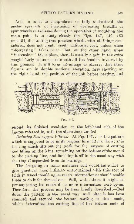
STUCCO PATTERN MAKING 263
And, in order to comprehend or fully understand the
modus operandi of increasing or decreasing breadth of
spur wheels in the sand during the operation of moulding the
main point is to study closely the Figs. 147, 149, 150
and 151, illustrating this practice which, with all things con-
sidered, does not create much additional cost, unless when
"decreasing" takes place; but, on the other hand, when"increasing
"takes pla^e, there is usually a gain in the extra
weight fairly commensurate with all the trouble involved bythis process. It will be an advantage to observe that these
figures are in double sectional elevation, first showing on
the right hand the position of the job before parting, and
FIG. 147.
second, its finished condition on the left-hand side of the
figures referred to, with the alterations wanted.
Reducing Non-capped Wheels. At Fig. 147, A is the pattern
which is supposed to be in its original form 12 ins. deep ;B is
the ring which lifts out the teeth for the purpose of cutting
and filling up the 3 ins. remaining on the bottom of the mould
to the parting line, and finishing it off in the usual way with
the ring B separated from its bearings.
The foregoing in some instances will doubtless suffice to
give practical men, hitherto unacquainted with this sort of
trick in wheel moulding, as much information as should enable
them to do it for themselves. Still, with others it might be
pre-supposing too much if no more information were given.
Therefore, the process may be thus briefly described : Bed
down the pattern in the usual way, and after it has besn
rammed and secured, the bottom parting is then made,
which determines the cutting line of the bottom ends of

264 FACTS ON GENERAL FOUNDRY PRACTICE
the teeth, as seen at D (Fig. 147). The ring B is at this
point bedded in, thereafter the parting is made to sweep
(Fig. 148); this sweep is cut on one side to 9 ins. for the
bottom parting, and 3 ins. to suit the top one. Great care
must be exercised in the formation of these partings, because
whatever these are swept to, the same determines the breadth
or depth of the casting. A study of the partings, and a
sketch also of whatever figure be under consideration, will
enable those interested to compare this sketch with the
following descriptions of any of the wheels represented by
Figs. 147, 149, 150 and 151. The procedure thus mastered,
the propositions as laid down become comparatively simple
to practical men. Lastly, when finishing top and bottom
sides of the boss (Fig. 147), get a print the diameter of
FIG. 148.
core wanted, and have it to project from the faces of the
boss to the amount it is to be cut top and bottom. Thus wesee the print referred to serves a two-fold purpose first,
to give the diameter of core ; and second, its thickness becomes
the guide determining depth of boss as seen on left-hand side
elevation of Fig. 147.
Increasing Breadth of Non-capped Wheels. Without goinginto details concerning the process of increasing the breadth
of spur wheels of this description, it will at once be seen that
Fig. 149 is an inversion of Fig. 147, as this job is simply
begun with a pattern 6 ins. deep, and finished off with a mould12 ins. deep as illustrated and explained. In further reference
to Fig. 149,-we at once see that the commencement of mouldingis practically the same as Fig. 147, and the first extension of
3 ins. is illustrated and written in plain English," mould."
It ought to be mentioned that the space referred to is
formed after the pattern is completely rammed up to the top

STUCCO PATTERN MAKINa 265
of the teeth, thoroughly tightened, and drawn with great care
to the point desired. But, whether a 6 ins. deep patternshould be drawn 3 ins. at once, instead of by two separate
draws, is a matter of opinion. However, I should say that
by adopting the latter method results will undoubtedly be
more satisfactory.
On the pattern being drawn to the exact spot, it is thereafter
made a fixture in its mould by tucking and ramming carefullyall round the webs of the arms, thus securing it for finishingoff the additional ramming of the teeth with safety, thus
giving the full depth of the teeth or casting when moulded,as illustrated at Fig. 149.
So far, we see, this last movement means a blank of 3 ins.
:'' v --- -" : ''
Mould
FIG. 149.
in the teeth of the pattern, until the top part is rammed upand the box parted. On this being done, the moulder must
now remove the blank sand from off the top of the teeth (see
Fig. 149). This done, he next draws his pattern with usual
care to the parting line, and when here, and fixed exactly to
the depth wanted, the top or last extensions of the teeth are
rammed according to the practice of securing teeth, and
swabbed with water, etc. ; the pattern is then in turn
completely taken from the sand, thereby completing the
extension of moulding a non-capped spur-wheel casting 12 ins.
deep from a pattern only 6 ins. deep.
The new pattern pieces for this method of increasing breadth
are made up of additional parts for the arms, as illustrated at
Fig. 149, and a similar extension to the depth of boss, shown
thus, X, on Fig. 149, embraces all that is necessary from the

266 FACTS ON GENERAL FOUNDRY PRACTICE
pattern-shop for increasing the depth of a non-capped spin-
wheel. Truly an economy in this division of foundry
practice, and most commendable where there is a patternto work from.
It is scarcely necessary to add that the ring B in Figs. 147
and 149 is used entirely for the convenience of finishing off
in superior fashion what might otherwise be inferior teeth
in these castings. The meaning of this will, doubtless, be
obvious without further explanation.
Reducing a Capped Spur Wheel. A glance at Fig. 150
shows, on the right-hand side, in double sectional elevation
the change that is made in a pattern 12 ins. broad, rammed
up in the floor, while on the left-hand side of the same figure
I* " *
{''
FIG. 150.
is seen the mould 6 ins. deep, which has been transformed
by the moulder to the reduced condition. Clearly this changeis most pronounced, and the process is altogether different
from the one described in Fig. 147.
Nevertheless, the modus operandi of moulding this job is
practically the same as that of the previous two examples givenin moulding
"non-capped spur wheels," that are either reduced
or increased in breadth. With this explanation of moulding
procedure we confine our remarks more especially to the
pattern and its adjuncts.
Assuming the core print to be correct on any given pattern
chosen for this purpose, and that all other dimensions (of
course, except breadth of teeth) are to specification, it must
now be noted that nothing is taken away, and whatever alter-
ations are required for this job become purely a question of

STUCCO PATTERN MAKING 267
how much a-side (new wood) is to be put on the pattern of
any capped wheel, to he altered for reducing the casting, say,
from 12 ins. to 6 ins. Further, whether it is a reduction from
12 ins. to 6 ins., or any other breadths or depths that may be
considered, it is, first of all, an operation in the pattern shopof dividing the difference by cleading both sides of the arms of
the pattern in the aggregate equally with wood to what is
wanted, when considering the reducing of capped spur-wheel
castings. Hence in the reducing of 12 ins. to 6 ins. there
must be 3-in. pieces of wood (BB, Fig. 150) nailed on the flat
faces of the arms; also, any additional wood that may be
required to retain strength and symmetry, and strength of"feather
"on the arms of the casting.
A study then of Fig. 150 becomes imperative A is the
original "flat" of the arm of the pattern, BB are the 3-in.
temporary or extension pieces that are used for the reducingmovement with this pattern, C is the ring as previouslyreferred to, and D is the top part.
The pattern, as illustrated with its cope rammed up, is
ready for parting, and when the cope is removed the moulder
immediately sets about to reduce by cutting and scraping with
the sweeps, not illustrated, but made in a similar fashion to
Fig. 148. The 6 ins. the moulder has previously arrangedfor scraping out must be done to size with a short sweep,suitable for working between the respective arms of the wheel
pattern; and, with the scraping of both outside and inside
partings, by these 6-in. checked sweeps, and thereafter the
finishing, completes the production of a mould for a 6-in.
capped spur-wheel casting from a pattern 12 ins. broad.
From a moulder's point of view it may be permissible to
add that the eyes of the ring C (Fig. 150) must be kept 6 ins.
short (i.e., when bedded in), otherwise, if placed to correspondwith the unaltered depth of the pattern (12 ins.) much trouble
would arise when returning the cope to its position as seen on
left-hand side of the figure in question.
Increasing Breadth of Capped Spur Wheels. Fig. 151, in
a sense, is a repeat of Fig. 147, at least, in so far as the
movements of drawing the pattern for extension are concerned.
The amount of pattern making is provided for by having

268 FACTS ON GENERAL FOUNDRY PRACTICE
sufficient clogs or blocks of wood for the entire increase
on the top half of the pattern. Therefore, assuming it
to be an increase of 6 ins., the blocks must be 3 ins. deep,
firmly fixed to the circle or rirn of the wheel, and placed
to suit the pinholes of the cap segments that encircle the
pattern. Herein is explained the whole of the pattern makingfor increasing depth of mould on the lines suggested ; and,
with the caps thus arranged, there is but little else to add
except to say that the method of ramming and drawingthe pattern is that laid down for Fig. 147. Also the move-
ments of "faking" and manipulating for a finish being all
the same, we only emphasise the importance of knowing in
:>.;.$/ ^
FIG. 151.
detail all connected with these figures on "special spur-wheel
moulding," either with or without caps, as the case may be.
Moreover, we may take it that just in proportion as we master
the various movements, which have been illustrated, of this
most important and economical branch of foundry practice,
so will our successes in handling this work which is quite
simple in practice be proportionately secured. See page 87
for further information on pattern making.
FOUNDRY OVENS AND THEIR CONSTRUCTION
Probably there is no question in founding on which opinion
is more divided than that of foundry ovens, and in point of
fact we find that ovens are as varied in their construction as
the buildings that bear the name of foundry. Hence it
frequently happens that in the most primitive types of

FOUNDEY OVENS AND THEIR CONSTEUCTION 269
foundries we find the improvised fire, with its plate resting
on bricks over the top of the flame, drying small bench
cores with an evident waste of fuel certainly not common to
modern up-to-date core ovens, which may either be fired with
gaseous or solid fuel. However varied the larger ovens may be
in their construction, the greatest difference lies in the method
of firing adopted, i.e., whether solid or gaseous fuel is used.
Ovens using solid fuels ("fuel ovens") have solid walls
and floors, but in the case of gas ovens the walls and
floors are as a rule more or less hollowed, with flues for
combustion.
Construction. In the first place we notice that all ovens
must have a chimney to carry off the steam and smoke and
to give the necessary draught for the combustion of the fuel,
whether solid or gaseous. It is not proposed to discuss at
any length the question as to which are the more economical,"gas" or "fuel" ovens, since it depends largely on the indi-
vidual requirements and conditions in each foundry. In a
general way it may be safe to say that, in jobbing foundry
practice at least, nothing can surpass the old-fashioned typeof oven with its solid walls and floor, and with the vent or
outlet flue in the floor or the extreme bottom of either
side wall.
There are some whose idea of an oven furnace or fire is
simply to form a box-like structure in a corner of the oven
which is most convenient for firing ; and with the necessaryfire-bars resting on a piece of cast iron, front hearth-plate and
back hearth-plate, and perhaps with an improvised door only,
their furnace is complete. Fireplaces of this type cause poorcombustion and inferior distribution of heat, which result in
additional cost of fuel and extra cost of time for attendance.
It is important, then, in the first place to provide sufficient
draught for the complete combustion of the fuel ; and a fire-
place, such as is illustrated in Fig. 152, will, when connected
with a suitable chimney, be found to answer admirably for
the heating of foundry ovens. It is not necessary to have a
separate chimney for each oven, as one chimney may be made
to provide sufficient draught for the successful working of
three or four ovens, while equally good results maybe obtained

270 FACTS ON GENERAL FOUNDRY PRACTICE
when the chimney is placed at some considerable distance
from the ovens. The hearth of all foundry ovens should be
placed on or about the level of the stove floor.
Materials. Of course ovens are, or should be, built of fire-
bricks or similar refractory material, and the more sub-
stantial the walls are made the more economical will be the
drying produced from them. But what is more to the pointas regards economy than anything else is the continuous use
to which an oven should be put in the drying of moulds and
cores. Ovens that are allowed to remain idle for such a
length of time as
will enable all pre-
vious heat to be
exhausted, and,
what is worse
still, to draw dampfrom its bottom
surroundings,or
retard the processof drying, thereby
intensifying the
additional cost
which follows the
drying of the con-
tents of an oven
that is only inter-
mittently in use.
A good thick wall all round and a roof of the same capacity
for retaining heat are points of economy in oven construction
as essential for the saving of fuel, with its consequent saving
in time and money, as the steam jacket that surrounds the
steam cylinder or the"composition
"covering with which
the steam boiler and pipes are covered. If the ovens are
to have the longest life possible, then there must be a thorough
binding of their walls, with vertical stanchions and horizontal
bolts right across binding these stanchions at suitable
distances apart.
A good type of bearers for foundry oven roofs is found in
the T section, cast according to the work they have to perform.
L
FIG. 152.

FOUNDEY OVENS AND THEIE OONSTEUCTION 271
These girders, as shown at Fig. 153, are very suitable for
carrying the roof, whether it be of cast-iron plates, or built of
arch brick, as illustrated. It not infrequently happens that
cast-iron plates are applied as substitutes for roofing and
last for many years when exposed to heat which is not above
normal temperature for drying loam cores. But even such
plates, although perhaps convenient material for a foundry,
may not always be the cheapest, and where heat of drying is
abnormal, a brick arch, as illustrated, and well padded, is un-
doubtedly the only way of roofing a foundry oven satisfactorily.
Situation. Ovens are usually placed at the ends of jobbing
foundries, an arrangement which goes a great way in keepingthe shop clear of undue heat, and is an advantage which adds
considerably to the comfort of the men in the foundry duringthe excessive heat experienced in most foundries throughout
FIG. 153.
the summer months of the year. Besides this the traffic
common to ovens is more conveniently out of the way at the
ends of foundries than when the ovens are placed along its
sides. Therefore end-ways for ovens in the foundry should be
observed wherever possible.
One of the principal points to be observed in selecting a site
is dry ground to build upon, especially with those ovens that
are built outside the foundry, and if the bottom of the furnace
pit or fire-hole be underneath the level of the ground on which
the oven is built, nothing short of good drainage all round
will suffice to keep the oven dry throughout all conditions of
weather. Where this has been neglected, or has becomedefective through the process of time, damp floors result
(sometimes actual water is to be seen), thus creating a waste
of fuel too apparent for further comment.But where firing is light and no intense heat from the oven
is experienced during the day, no objection need be raised

272 FACTS ON GENERAL FOUNDRY PRACTICE
about situation, even should such be practically in the middle
of the shop, as may be seen in some of our "bank-pipe
"
foundries. A core oven in the centre of four "banks"
employing green-sand pipe moulders, four benches for
making the cores, possibly of various sizes, and two carriages
for the convenience of drying the cores with all the equipment
necessary, is a situation satisfactory to all concerned. All
firing required for these cores being in the night time, no
inconvenience from heat, as previously referred to, is
possible at least to any great extent.
Firing the Oren. It is a peculiarity of good drying that
moulds and cores as-
a rule require to be treated separately ;
and for that reason cores, especially if they be of straw
and loam composition, are exclusively dried in what is
known as the core oven. Mould drying is constant, but core
drying on the lines suggested is of necessity intermittent, and
the firing suitable for the latter would be too slow a process for
the former, while on the other hand the firing necessary for
moulds in general would spell destruction for cores of the
class referred to. Likewise constant heat in a core-oven is
impossible, because of the frequent opening and shutting of
the doors of a core-oven working under normal conditions.
Such frequent opening of doors would in the case of a mould-
drying stove retard drying, and such a loss of heat as this
entails, altogether apart from time, would make the cost of
drying moulds in the coreo-ven unnecessarily expensive.Hence the necessity for separate stoves where work as
indicated can be found for them. Oven-firing in the foundryis always best and -most economically performed when the
moulds occupy all available space for drying and when the
ovens are kept practically constantly under fire.
Gas-Drying Ovens. In gas-producer ovens there are at
least two systems, namely, those which are installed with
gas producer and steam boiler separate, and others of a
much smaller and less pretentious type, placed alongside of
the ovens, generating gas and the necessary steam for com-
bustion. The former of these systems in gas oven construc-
tion and drying has long been tested, and to many it seems
the only way of drying economically ; the latter is of a much

FOUNDRY OVENS AND THEIR CONSTRUCTION 27,'i
more recent date, but through the process of time mayyet form a rival in gas drying on a smaller scale to the
old-estahlished installation of gas drying referred to.
The arrangement of flues in gas oven construction is part
of the secret, if it may be put so, belonging to the system,
and wherever it is adopted the flues must be designed to meet
the peculiar needs of the branch of founding practiced. Conse-
quently the flue arrangement of a vertical pipe gas-drying oven
would not work economically if adopted to dry the work commonto jobbing foundries. A good average pipe foundry oven for
vertical drying must measure from rails to roof from 12 ft.
to 17 ft., and sideways anywhere between 8 ft. and 5 ft. and,
say, 40 ft. long, while that of a jobbing foundry may approxi-mate 30 ft. long by 12 ft. by 10 ft. high or otherwise,
according to work done. From the foregoing we see the
need of thinking out the matter with those who makeoven construction and drying their specialty. However, it
might be pointed out in passing that the ratio between gasoven capacity and their gas producers, roughly put, works out
approximately at as 1 is to 30, and between steam boiler
capacity of the Cornish type for such work and the producersas 1 is to 4.
Having referred in brief to the difference of construction
and economy in drjT
ing existent between gas and coal
ovens in the foundry, one would do well to examine
minutely the claims of each. With gas pre-eminence is
only possible where large quantities for oven drying are
imperative, and systematically consumed every day. But
before adopting this process challenge and scrutinise the
method proposed, and most especially as it relates to first
cost and upkeep.The calculations given above refer to an installation of
twelve stoves, with an average capacity of 32 ft. by 10 ft.
by 12 ft., and of course these must be subject to modification
or alteration proportionately (and especially in steaming
capacity) when a smaller installation is considered.
Ovens for drying purposes in foundries are absolutely without
limitation in design and construction, and a small gas oven
fired with a supply of corporation gas, burning from a simpleF.P. T

274 FACTS ON GENERAL FOUNDRY PEACTICE
arrangement of jets, can be made to dry small and mediumcores at a cost per hour cheaper than an oven for similar
work using solid fuel of any description i.e., if the gas in
question be at hand and of moderate cost.
FUELS
The question of fuels for founders and those interested,
either from its commercial or practical side, is of intense
importance, and in a very special degree is this the case with
founders that do a large business in dry-sand and loam
castings. Fuel in foundry work consists principally of coke
for the cupolas, ovens, gas producers, chaffer or fire-lamps,
and hot air dryers. For these purposes cokes of all gradesand prices are used; the highest quality being used for melting
metal, and all others are either directly or indirectly used for
the drying of moulds. Coal in many foundries is used for
drying purposes, especially where gas, hot air, and the newer
modes of drying have not yet been brought into practice; also,
where the improvising of fires for jobs in the floor, in the old-
fashioned method of drying with "lump coal
"of good quality>
and the common grate of the oven which works unaided byforce draught, are still in practice. The list of fuels that are
used in the foundry also includes dross for steam raising and
in some places for gas producers, oil for crucible melting, and
charcoal to a limited extent for annealing.The testing of fuels is much the same as the testing of
blackings, that is to say, nothing but actual contact with the
work these have to perform in practice will definitely
determine their true character and value for the foundry.
Therefore, it is only by observation and experience that we
get to know the fuels that are most suitable for use in the
foundry or elsewhere. This is most manifest in the selection
of coal for grinding into coal-dust for the mixing of green-sand
facing sand, a material of great importance in this division of
iron founding.Coal and coke mixed in suitable proportions are frequently
used in"chaffer-drying," a practice much in evidence where
"skin-drying
"of green-sand work is necessary, and is of

FUELS 275
daily or hourly practice in loam moulding, either for hurryingon the drying of
"rough coating," or the drying of moulds in
this foundry department, preparatory to an absolute finish by
blackening, etc. Coke by itself is an unsuitable fuel in some
cases for this purpose, as it burns with little or no flame
owing to its deficiency in volatile combustible matter. Abituminous coal which burns with a moderate flame gives the
best results for the drying of moulds by open fires. A lean
or anthracitic coal which burns with an almost smokeless
flame is but little better than coke for the firing of
moulds in the floor without forced draught, but such a
coal is usually suitable for making coal-dust.
It may also be mentioned that the greater the depth of a
pit-fire below the floor level, the more necessary a flaming
coal, within certain limits, becomes. These pit-fires beingnot infrequently in the form of miniature bonfires, the heat
rises to the highest part, a distance at times considerable, and
thus enables the extreme top of the mould, so situated, to be
thoroughly dried. Fuels as indicated here, usually give a
nice brown tinge to the mould, and where this is apparent,other things being equal, a beautifully skinned casting is as a
rule a foregone conclusion.
Coke. First, we consider this from the standpoint of
cupola practice, and in this the quality of coke is one of the
most important things in melting iron, because iron melted
in a cupola is in constant contact with the fuel. The best coke
for cupola melting must be able to sustain the burden of the
charges of iron in the cupola. From 8 to 10 per cent, ash
may be taken as a fair average, and it should not contain
too much volatile matter as this aggravates the tendencywhich cupolas have for "bridging" or "bunging," an
error in melting metal which means so much lost to the
foundry.With good coke sulphur should not exceed 0*50 per cent.,
which more or less finds its way into the castings, the best
of metal thus becoming considerably affected, especially as it
relates to mechanical tests both transverse and tensile.
Taking the market prices of good and bad coke, it will be seen
that the difference is comparatively trifling; the wonder is to

276 FACTS ON GENEBAL FOUNDRY PEACTICE
practical men how some cokes find a place in the market as
cupola cokes at all. Such good luck for the coke merchants
is the outcome of the inefficiency of the buyer, and his
absolute want of knowledge of the points that go to make
good coke for cast iron cupola melting.From 10 to 15 per cent, in price is all that exists between
good and bad coke for cupola purposes, and for this some take
the cheapest, which invariably retards melting, which in turn
reduces output from the cupola considerably, gives inferior
running metal, and of course as a result inferior castingsalso. These results, with additional expense of fettling the
cupola, caused by abnormal waste of time and material, not
to mention unnecessary worry, merely for a paltry few
shillings, condemns such practices as a penny wise and
pounds foolish policy in foundry management.
Dry coke of good quality is lighter than water, therefore
it is worth while noting the condition in which it is received,
as it passes over the weighs, and compare this with the pay-ments. Some make it a point to keep all cokes under cover,
but a certain amount of water or moisture are necessary to
give improved working in the cupola.
Good cupola cokes are dark grey in colour, very similar to a
No. 4 iron, sonorous and of a semi-metallic lustre, and to the
practical man sight, sound, and density are, apart from
analysis, however useful and necessary this may be, the
methods by which he determines good from bad. If to such
experience is added the knowledge gained by the chemist in
the laboratory, the working of the cupola cannot fail to be
improved.The variable density of cokes causes mischief in the cupola
unless the man in charge of it knows how to watch and
work all grades according to their own peculiarities. And,as a matter of fact, the weight or measure of coke, which
forms the "bed on the hearth" of the cupola may whenanother coke is used be altogether insufficient for the purposeintended. Doubtless the absence of this knowledge has
prematurely"bunged up
"cupolas by pig metal getting down
in front of the tuyers, through insufficiency of density in the
coke to maintain the melting zone of the cupola in its

FUELS 277
normal position and condition throughout the various stages
of the melt.
A coke for melting iron in a cupola may have a high calorific
heat value, but its want of density may condemn it as a first
class cupola-coke, because insufficient density gives inefficient
resistance to the load of iron charges in the cupola, and, as
already indicated, precipitates the iron too hurriedly down to
the melting zone, thereby reducing the melting capacity
of the cupola, besides producing badly melted metal for
castings.
Further, fuels for cupola foundry practice have remained
very much the same as when cupola and crucible were the
only processes of melting metals in iron and brass foundries.
One would have thought that, with the advent of the hot
blast at the melting furnaces in 1828, and as patented by Mr.
Neilson, and first adopted at Clyde Ironworks, near Glasgow,and the great development in output and cheapness of steel
and malleable iron since Bessemer, in 1856, read before
the" Cheltenham Meeting of the British Association
"his
wonderful paper entitled," The Manufacture of Malleable
Iron and Steel without Fuel," should have brought a changeere now.
It is thus a matter for surprise that cupola practice in the
foundry, and its relation to fuels, solid or liquid, remains prac-
tically the same as it was prior to any of the improvementsin smelting and melting referred to. But, while this is so,
much has been done with regard to fuels in crucible melting,within certain limits in the finer metal castings trade. This
is specially so in the melting of large quantities of the finer
metals. Still, where heavy melting is not imperative, the
crucible, with solid fuel in the form of coke of a medium
quality and low in calorific intensity, or coal, aided by
chimney draught, is, in the opinion of the writer, cheapestand best, for small melts of all metals without distinction, even
to cast iron, which, by the way, many foolishly imagine can-
not be melted unless on the lines of common cupola practice.
The process of"liquid fuel meltings
"is but, perhaps, in
its infancy, and the progress made by the different methods
for a number of years back has, to a considerable extent,

278 FACTS ON GENERAL FOUNDRY PRACTICE
yet to be tested. It should be noted that, so far, any sub-
stitute for crucible furnace melting on the old lines has
got to be done by the aid of a blast. But whether it be whatis known as the
" Brass Melting Air Furnace "or those types
of furnaces burning"
oil or gas," as, for example, the"Cbarlier
Furnace," in both cases the saving to a very great extent,
if not altogether in the cost of crucibles, is a foregoneconclusion.
The air furnace for heavy brass casting, where the metal is
tapped like an ordinary foundry cupola, as is the case with
"Meyer's Patent Brass Melting Air Furnace," is verycommendable for heavy work, and is a great improvement on
melting with, say, eight or ten 300 Ib. crucibles for a heavybrass job, and pouring their contents into a suitable foundryladle to cast the job intended : a practice not uncommonbefore air furnaces for melting brass were introduced, and
may even in some cases be seen at the present day.
Non-Cupola Coke Fuels. The cokes which come under
this title, include those used for the drying of moulds, and
the manufacture of "producer gas" in the foundry, and for" hot air drying by portable fires
"; all of which, from the
common "slack
"or cinder, to the superior anthracite coke
are, however serviceable in the foundry, but the by-productsof the gas works. The former of these so-called cokes is of
little account when used by itself, but the calorific power of
the latter being so much greater than the former makes it
much sought after by the founder, for drying with the
portable hot-air dryer, a method of drying which does awayto a very great extent with smoke and the obnoxious
gases in floor drying, a thing so detrimental to the
health of the foundry workers. This, apart from the
economical side of the question, where there is room and
work for its adoption, will undoubtedly make the" hot air
dryer"supersede all other antiquated methods of drying in
the floor when such is necessary.In the use of these cokes in the foundry there is an
inclination to expect too much, and in that way chaffer
firing is retarded. The best of them ought to be assisted bya little live coal for this purpose, and so facilitate combustion,

FOUNDEY TOOLS 279
which in turn gives improved results in drying, with a
consequent saving of time also. Of course the slowness
with which these cokes (when normal) burn in the fires in
question is entirely due to the want of blast or reinforced
draught of some kind or other. Cokes of this class must
have some sort of forced draught, otherwise their use for
drying purposes in the foundry is not commendable.
It is evident then that forced draught of some kind or
other must be considered where hot-air drying as a systemis to be adopted, and for this purpose a blast pipe
arrangement for the foundry becomes indispensable to an
extent proportional to the wants of business anticipated
in this direction. However, this need not be taken too
seriously. For instance, under certain circumstances a small
pipe direct from the steam boiler, applied to the hot-air
dryer, will give equal satisfaction, in so far as the workingof a "
hot-air dryer"
is concerned. And with this method of
blowing, if superheated steam be applied, and coke of normal
quality be used, results will thereby be proportionately
greater. However, steam from 30 Ibs. to 40 Ibs. pressure
may do all that is required, and by this method of blowingthe coke, fire engine and fan are at least dispensed with.
FOUNDRY TOOLS
In the matter of tools as distinguished from plant there is,
perhaps, but little to say in so far as the tools of a jobbing
foundry are concerned. Consequently the question becomes
focussed within somewhat meagre limits, i.e., if we exceptthe hundred-and-one nick-nacks that are known as tools to
moulders, although these with rammers, riddles, barrows,
shovels, and coke baskets, etc., etc., in goodly supply, are all
items to be considered in furnishing tools for the foundry.
Further, there are tools for the cupola, sling-chains and
hooks of various types (as will be seen further on as crane
furnishings) for the lifting and laying of the variety of loads
known to founding in all its branches. These, if we include
pneumatic tools and portable hot-air drying fires, can only be
touched upon briefly as we proceed.

280 FACTS ON GENERAL FOUNDRY PRACTICE
Shovels. In this connection it may be said to profit that
one of the first things a sand moulder should have is a goodshovel. Give a man a shovel he can call his own, at least
while he is in any given employment, as by doing so he thus
takes an interest in keeping it in good order, and thereby the
lengthiest possible existence of the shovel is guaranteed, and
the owner for the time being will do more for his money than
is possible where this habit is not practised. Nothing wastes
a shovel so much as its being badly kept, and what is every-
body's business in thh matter is, to use a hackneyed phrase,
nobody's business. Therefore, if the shovels provided for
moulders in a foundry be not distributed on the lines suggested,
but scattered here and there, as it were, on the foundry floor,
FIG. 154. FIG. 155.
the property of all alike, cleaning, trimming, and otherwise
oiling, at the end of the week, of such shovels will undoubtedlybe utterly unknown, and as a result deterioration and its
consequent loss to the employer will inevitably follow. This
loss is intensified by unnecessary exertion on the part of
the employee, the minimum of work being done by the
maximum of physical effort. To those who have never
counted the cost, the foregoing may appear a small matter;
nevertheless, it is one of those factors of waste, or leakage,
often too lightly passed over, and a foundry badly equippedwith this simple tool means money wasted in every phase of
founding ; indeed, this leakage is to be found in some of
the shops where one would least of all expect to find it. Oneof the most painful things for a foreman to endure is to see,

F
FOUNDRY TOOLS 281
it may be, two or three men waiting their turn for a
shovel or some such tool throughout the process of mouldinghis job.
A penny wise and pound foolish management is in part, as
a rule, embodied in an inferiority and scarcity of tools, and
as the shovel has 'been taken as an example, one can onlyadd that the shovel or spade which cannot cut clean in diggingand thereafter discharge its contents easily, should be
attended to and put right, in a similar way to the machine
that is failing to keep up its output through lack
of repairs. What applies to the shovel in this
respect applies to all tools alike in the foundry,and were more attention paid to those seemingtrifles as they here and there exist, more satis-
factory results would undoubtedly follow. In-
difference as to condition and supplies df%the
minor tools, not to mention aught else, means
money wasted which otherwise could be saved.
Beams. The beam for turning moulding
boxes, as illustrated at Fig. 154, and which
could be illustrated in many forms and sections
(were it not that brevity forbids it) is a common tool of
long standing in specialty or jobbing shops. The beamlinks and stirrups which constitute the beam as a whole
are illustrated in Figs. 154, 155 and 156. Of course, other
designs with a more costly equipment might easily be given.
Suffice it to say this type, for economy and handiness for
such jobs as tank plates and things common in jobbing work,
is not likely to be excelled. These beams, light or heavy,where good practice is attended to, are all made from hard
wood, and mounted or trimmed, in some cases, elaborately.
All the same, a handy jobbing moulder is not often at a loss
for a tool of this kind, because if he cannot get one of
wood then his next shift may be some sort of a beam in
malleable iron, but if beaten here also, he will fall back on the
inevitable, namely, cast iron, and cast one somewhat similar
in section to Fig. 158, B, which in all probability would serve
his purpose very well, especially if it were a case of lifting
some check or cope from 10 to 15 tons' weight, and also act
y

282 FACTS ON GENEEAL FOUNDKY PEACTIOE
as a valuable weight and binder for weighting or binding a
cope or top part. However, take Fig. 154 as a pattern in this
respect, and, of course, of any section desirable, then by substi-
tuting a strong sling chain for the links, as seen at Fig. 154,
a very good beam is formed for heavy lifts in the class of work
suggested. Hence, with S and C hooks and ropes, or perhapschains although chains are not so handy as ropes here one
can lift comparatively easily in this way any load within the
strength limits of the beam and lifting capacity of
A any given crane that may be employed for such work.
, ^C Such are the stratagems in jobbing moulding that' the term tool is really ambiguous to a degree,
and is doubtless without limit in its application.
This is borne out by the many devices the moulder
has to resort to in his everyday work, so to speak,
in the foundry. In short, a jobbing moulder, to
be successful, must be a man of many shifts, as he
has frequently to make tools in jobbing practice out
of what, to the uninitiated, may appear at times to
r' be nothing more than a heap of dumped cast-iron
FIG 157scraP or perhaps malleable and cast iron, as the
case may be.
Clamps, Ringers, Binders and Stools. The uses to which
this quartette of tools are applied must be considered collec-
tively, because where we find the one tool, we usually find all
of them in some form or other doing their share of the work
at the binding of some cylinder, condenser, bottom, or such
castings as require abnormal strength of binding to secure the
mould and cores at the time of pouring.
While the foregoing is the prime duty for which these tools
are made, their usefulness for other purposes in manyfoundries cannot be overestimated, but need not be further
referred to at present.
Clamps. Figure 157 represents a common type of cast-iron
clamp usually employed for the clamping of boxes or copes
previous to casting. These tools are made to manydimensions, particularly in length and section, and may weigh
anywhere in pounds from 5 to 500;and when such weight as
the latter is necessary, the eye A, as seen at Fig. 157, is very

FOUNDRY TOOLS 283
serviceable for slinging purposes and thereby binding them
comparatively easily in their places on their respective jobs.
The grasp, or distance between the toes of these clamps, maybe anywhere from 3 ins. to 6 ft. or 8 ft. as required. Someresort to malleable iron, about 2 ins. square, for the makingof these clamps when beyond the smaller dimensions. Still,
experience in both types has declared cast-iron clamps, as
illustrated at Fig. 157, to be by far the safest, cheapest and
best for work that usually goes by the name of "pit moulding,"
i.e., where binders and ringers are not adaptableor perhaps procurable.
Ringers and Binders. In Fig. 158 there is
shown a sectional elevation of ringer and binder,
which is given in this form for convenience of space.
Also, these are both shown in section as they
appear together at the binding of any job that is
about to be cast where this sort of moulding is in
operation. A, in Fig. 158, is the ringer, and
B of the same figure is the binder ; these ringers FIG. 158.
are, as a rule, made from malleable iron of,
say, from 1 in. to 2 ins. square, and are used for many other
purposes in the foundry besides binding; and, of course,
the binders are all made from cast iron, and vary in section
and design according to the needs or wants of the foundry. Cis a small oblong piece of iron, preferably malleable, and is
placed, as shown at Fig. 158, between binder and ringer for
the purpose of bedding both to each other the better, as also
the safer and more solid driving of the wedges during the
process of binding any job preparatory to casting it. Obviouslythe foregoing on "
binding"
clearly indicates the use of
wedges in this division of moulding. But while this is so, it
must be borne in mind that for a similar purpose, namely, the
holding down of copes and such like as previously suggested,
bolts are used in specialty work and where, as a rule, no
ringers are employed. The binders in such cases have special
oblong holes cast in them for bolts passing right down
through binder and casing flanges or otherwise, and by this
simple device the job is bound by the tightening of the bolts
with their respective nuts. This is a practice common to

284 FACTS ON GENERAL FOUNDRY PRACTICE
marine cylinder work, which does away with the use of clampsand ringers altogether; and, wherever in operation, facilitates
the making ready of a job for casting.
Further, where average spherical pit work or such-like is
cast, the ringers, as illustrated by A, Fig. 158, for safety and
handiness of working, should be made to lengths, thus : 10 ft.,
6 ft. and 2 ft. Six to each of these lengths, with stools as
seen at Fig. 159, may be regarded as a foundry pit's tools for
binding any job capable of being cast in it.
It is a good feature with short ringers to have them made
with a crook at one of the ends instead of being square at both
ends, as by this means extensions are easily made
by simply hooking the crooked end through the
end of the square ringer and thereby getting the
desired extension a convenience often requiredat pit casting.
Stools. Three favourite lengths to this designare given as follows : 24 ins., 18 ins., 12 ins. and
6 ins. (see Fig. 159). All these different lengths
may be made from the one full length of pattern by shifting
the top, 5, inwards to the lengths stated. Thus is summarised
the four principal tools used in the binding of pit work in
a foundry.
Having previously referred to C an^ 8 hooks, these
with, crane-sling chains, Figs. 160 and 161, embrace all
that as a rule is classified as crane furnishings. Each of these
has an individuality its own, and to take each in detail
and stipulate its special duty in the foundry would take
more time and space than we have at our command. The
following, however, may be said : C hooks and S hooks are
made from J-in. up to 2 in. round iron or even more, the
latter being pointed or formed at one of the ends as well as
lengthened to suit the peculiarity of the work for which these
S hooks are designed and made. The C hook is best suited
for heavy work and when slinging with a chain it is very
handy for passing through the "loop
"or
" bow "of the chain
as it appears when doubled up at medium and heavy lifts.
Also this hook for similar work is most serviceable for
lengthening sling-chains where shortness is a difficulty, and

FOUNDRY TOOLS 285
where the sling-gabs of same are at times unfavourable for
catching up what may be comparatively easy for the hooks in
question.
Figure 160 is a screw hook, and when these are attached to
each end of a "triple sling chain," prove themselves to be
very handy tools wherever exact level slinging is imperative.In point of fact, where " the sling of three "is in
practice, as we often find it to be the case with
cores, a sling chain of this kind is absolutely
necessary that is to say, if method and economyis of any importance at all. Where the triple-
sling chain as suggested cannot be profitably em-
ployed, a single screw hook, as seen at Fig. 160,
for general lifting purposes will prove a very
handy and profitable tool in most jobbingfoundries.
Fig. 161 illustrates what is known as a "double
hook," and the top crook A which lies at right
angles to the right and left section of this hook
makes it an indispensable tool in foundries that
have two or more cranes (especially derrick) in
the foundry. But whether this be the case or
not, it is a very handy tool, apart from its
uses in shifting from derrick to derrick the
miscellaneous loads in the everyday work of a
foundry wherever the"traverser
"is not yet in opera-
tion.
Pneumatic Tools. Tools of this description are gainingmuch prominence in foundry practice, and to some are the
acme of perfection in this sort of foundry equipment and that
of the fettling shop as well. But it is with this, the latest
improvement in tools, as it has been with the mouldingmachine which, by the way, is no new invention that is,
failure has in some cases followed the adoption of pneumatic
appliances, because of misapplication and the ignorance of
the buyer, or perhaps by what is called the good business
capabilities of the patentee of such tools or his representativein business.
In this connection, it may be permissible to say, that more
FIG. 160.

286 FACTS ON GENEBAL FOUNDRY PRACTICE
than thirty years ago the writer saw moulding machines
scrapped that had been doing duty every working day for a
number of years previously. These machines not having given
the satisfaction anticipated, their owners returned to the old
stereotyped method by bedding down the class of work
referred to in the floor, not turning over with bottom and top
flasks as most moulders would imagine, and are continuing
to do so up to date, and at a cost considerably less per
casting than was possible with the machines in question.
And just one other case in point, one of the largest foundries
in the United Kingdom equippeda certain class of work with tools,
plant and patterns of the latest
type in hydraulic machine mould-
ing, at a cost of many thousands
of pounds, and after working this
plant for all it was worth for
FIG . i6i. a considerable time, this firm
also had ultimately to consignthis costly and special hydraulic machine plant to the scrap
heap.
These, as stated, from actual experience are enough to
shatter the belief even of many who hold strong convictions
in the utility of mechanical appliances and their adaptation to
foundry practice, whether these be manipulated by wind, water,
steam or electricity.
The one grand question to decide with these tools is
their suitability, whether it be with moulding machines
or pneumatic foundry tools of any description at all. Never-
theless these tools and machines have their place in the
foundry and can be applied to much profit when judiciously
thought out and adapted to a field of work absolutely suitable.
To make sure of this, one must listen attentively to what is
being said about any particular tool or machine, and if
what has been said applies to one's work, and is confirmed by
experience, then to such an extent the safety in adoptingmachine or pneumatic tools of any kind becomes compara-
tively secured. Of course it takes much experience to decide
such matters, and if this be wanting, losses in such purchases

FOUNDRY TOOLS 287
to a greater or lesser extent will more than likely follow, and
the prejudice, too common amongst many, for an improved
foundry practice become intensified through such failures as
herein suggested.
Pneumatic tools in the foundry are now almost too nume-
rous to mention, and whether it be for actual foundry practice
or fettling, the wants of either are now largely catered for by
foundry furnishers of every description. In the foundry there
are nowadays pneumatic ramming, riddling, sifting, and
blowing of moulds. Also, for' :
blazing"
during the process
of skin-drying moulds, and even for the drilling of holes in
flasks in different parts of the foundry, the pneumatic drill
tool is to be found doing such work profitably in some of
the up-to-date foundries in the country.
A great saving is claimed in the fettling shops since the
introduction of the pneumatic hammer and sand-blast processof cleaning castings, which is said to give an improved skin for
painting or otherwise. These do not exhaust all that pneumatic
application can do in the foundry, but it is doubtful whether
the use of them for such work as"chilling metal for specific
purposes"
is advisable. Here follows a quotation from an
up-to-date journal loud in the praise of pneumatic tools for
the foundry :
" In some classes of long slender castings,
such as piping, where the cores are built round a thin tubing,
and, as is sometimes specified, chaplets have to be sparingly
used, the cooling effect of a current of compressed air will be
found a very useful and convenient expedient to use to pre-
vent the core being lifted in the middle by molten metal."
The above appears to the author to be entirely opposedto sound practice.
Gas and Hot-Air Driers. For a goodly number of yearsthe drying of moulds, particularly of the larger class, outside
the ovens or stoves of the foundry has been done by gas, and
by what is known as the hot-air process of drying. The first
of these processes, in which what is known as the Bunsenburner is largely used, is a process of drying suitable
either for horizontal or vertical moulded work, but preferablythe latter
;and in point of fact, this process is mostly employed
in ingot-mould casting and vertical pit-pipe moulding. But

288 FACTS ON GENERAL FOUNDRY PRACTICE
for drying moulds in the floor, the "portable hot-air drier
"
that is usually fired with gas coke is by far the handiest and
most popular system of drying moulds outside the foundry
oven, whether in loam or dry-sand practice.
However, it may be questioned whether hot-air driers of anyk:nd can be regarded as tools, although these are of a portable
construction, and are moved about for duty in the drying of
moulds in the floor as referred to. Suffice it to say, these
rank as of first-rate importance, where floor drying is an
absolute necessity. Therefore, whether the portable hot-air
drier be considered foundry equipment or a tool, such is really
immaterial; but as an adjunct in this division of founding,and by its serviceableness in the drying of loam and dry-sandmoulds in the floor, its adoption is more and more manifestingitself to the advantage of all concerned in the foundries doing
heavy and medium loam and dry-sand castings.
The many types of hot-air driers in the market in these
days are largely, if not altogether, confined to the class that
are blown by air in some form or other. This is all the more
surprising when, as a matter of fact, and as previously stated,
steam can be applied with equal usefulness for the same pur-
pose, thus doing away with the service of the engine and fan
which are absolutely necessary for blowing the hot-air drier.
A small steam jet applied in a somewhat similar way to the
one that admits the air for the blast pipe fitted up in the
foundry for those hot-air driers will do the work of blowing.
Also, the steam pressure need not be above 40 Ibs. on the
square inch, but the higher the pressure the better the blow,
and the jet for admitting the steam to the fire should not be
of greater diameter than is required for a needle to pass
through it.
The popularity of this system of drying is evidence of its
superiority over the old-fashioned way of drying floor work bycoal which was usually of a superior quality, and with impro-vised fires or chaffers as the case may be
;and the waste of
coal and coke (the latter not so frequently used as the former)when compared with the modern hot-air process of drying is
all too well known to experience to admit of further comment,
i.e., wherever consecutive floor drying is necessary.
FOUNDRY TOOLS 289
Apart from the commercial side of the question of dryingin the floor, (and as previously mentioned) the hot-air processhas on the grounds of improved conditions for all who work in
the foundry much to commend it, as by this system a purer
atmosphere than was possible in the old system of drying is in
a measure guaranteed. This, if nothing more, is quite enoughin itself to make it commendable. It is a fact that by far the
greatest proportion of moulders or foundry workers on inside
duty are prematurely affected by chest troubles through the
density of smoke common to such foundries where coal drying
consecutively in the floor by the old system is practised.
Although by this new process of drying we do not maintain
that the smoke nuisance in the foundries with the class of
work suggested is entirely got rid of, still at the same time
the very considerable reduction in the amount of smoke
improves the working conditions in similar proportion.
Obviously, illustrations of any particular type cannot be
judiciously given, but with the hot-air driers as with other
tools, individual circumstances will dictate individual wants,
and the foundry furnisher will best supply the rest.
As a matter of fact all hot-air driers are much the same in
practice, but a good type is designed with air-regulating
chamber, fire-box, and hot-air chamber. Besides what has
been stated, the air supply may be attended to by a small
blower and motor, and, if desired, can be directly connected to
the drier.
Perhaps the best and most economical way of working
these"driers
"is to install a line of 5-in. air piping along the
walls of those foundries doing much floor drying, and with
suitable branches to attach the blast pipe to the portable air
driers, as the exigencies of the everyday work of the foundry
demands. For blowing these driers, which are best fired when
using good gasworks coke, air at an approximate pressure of
2 or 3 ozs. to the square inch should be ample.
F.P.


INDEX
AGRICULTURAL castings, metal for,
76
Aluminium alloys, 228
brass and bronze, 229
bronze, 215
charging the crucible for, 225
demand for, 229
gating of, 224
malleability of, 229
melting of, 224
moulding, sand suitable for,
228
price and specific gravity of,
228
specific gravity of, and scab-
bing, 222
temperature for, 226
unalloyed, 225
Analysis, chemical, of English and
Scotch pig irons, 235 240
Analysis, chemical, of moulding
sands, 14
Annealing chilled wheels, 156
malleable cast iron, 232
BANK pipe core boxes, 249
pipe patterns, 248
pipes, cores for, 148
Beams for foundry use, 281
Bell-mouthed pipes, 97
Bend pipes, 99
Binders, 282
Black-sand, 20
Blistering of cylinder castings, 119
Blowholes and shrmkholes, 30
Bogey-wheels, design of chills for,
154
Boiling points of metals, 246
Boss patterns, air vessel, 92
Bottle-neck pipes, 96
Bottom of moulds, pressure on,
58
Boxes, 6
Branch pipes, 98
Brass castings, cooling, 214" draw "
in, 210
moulding, 208
position of casting,
211
foundry, cellar or ashpit for
a, 206
furnaces, 204
temperature of casting, 209
wastage in melting, 209
Bronze, aluminium, 215
and brass aluminium, 229
phosphor, 215
plug gating of, 216"Burning
"cold castings, 33
heating castings pre-
paratory to, 34
CAMBER and uniformity of cooling
castings, 51
Casings, pipe factory, 163
Casting facedown, 24
position of, dry-sand cylin-
ders, 122
job pump pipes,
106
Castings, sandless, 156
Chaplets, creosoted, 44
on polished and un-
polished parts, 42
tinned, 43
Chilled cast-iron wheels, 154

292 INDEX
Chilled wheels, annealing of, 156
Chills for bogey wheels, design of,
154, 156
metal most suitable for, 155
C-hooks, 284
Clamps, ringers, binders and stools,
282
Coal dust, 19
for facing sand, 19
Cokes for foundry uses, 275
good cupola, 276
Colour as the indicator of tem-
perature, 79
Compressed gas sustaining a
mould at the time of pouring,41
Condenser patterns, 251, 252
Cooling brass castings, 214
Core boxes, bank pipe, 249
gum, for cores, 28
Core-irons and cores for pipes, 100
making for dry-sand cylinders,
119
pump-pipe, 105
sand, medium, 137
Core sands, core-irons, and cores,
132
sands for large medium and
small cores, 136
Cores for bank pipes, 148
for green-sand pipes, 147, 148
gas-engine cylinder jacket, 131
green-sand, for pipes, 147
gum water for, 28
jacket cylinder, for petrol
engine work, 133
jacket, for loam cylinder
moulds, 127
method of placing, in S.V.
cylinder mould, 185
placing Corliss cylinder, in
dry-sand moulds, 145
sand for small, 138
sand jacket, 126
screw hooks for slinging, etc.,
285
steam cylinder jacket, 126
Cores, vertical dry-sand pipe, 150
vertical loam pipe, 149
Corliss cylinders, casting, three
core method, 140
Corliss cylinders, casting, five
core method, 142
Corliss cylinders, casting, seven
core method, 143
Cotter cores cast in rams, 85
Cranes, 6
Cupola and melting, 10
charging the, for cylindersin a jobbing shop, 73
cokes, 276
for melting malleable cast,
230
Cylinder castings, blistering of, 119
cover castings, defects on,
86
moulds, finishing dry-sand,117
in dry-sand, ram-
ming, 116
Cylinders and engine parts, metal
for, 74
in dry-sand, venting, 116
DAMP floors, 200
Design, tank plate, 49
Diagonal bars and shrinkage, 48" Draw "
in brass castings, 210
speculum metal, 218
Drying an air vessel core, 95
gas and hot air, 287
ovens, gas, 272
Dry-sand, 15
and dry ashes in loam mould-
ing, 200
cylinder moulds, closing, 120
finishing, 117
cylinders, core making for, 119
position of casting,
122
facing sand, 21
gating cylinders in, 124
moulds, temperature of metal
for, 82

INDEX 293
Dry-sand, venting cylinders in,
116
EQUALITY of metal, 50
Examples of feeding, 66, 67
FACING sand, dry-sand, 21
for gear wheels,
green-sand, 19
green-sand light, 16
heavy and medium,16
milling of green-sand,
18
Feeding automatically by hot metal
only, 70, 71
by one rod only, 68
decentralised, 67
open-sand castings, 70, 71
or compressing open-sand
castings, 69, 219
Finishing dry-sand cylinder moulds,
117
Flasks, their use in loam moulding,
195, 196
Foundry floor, the, 5
oven construction, 269
tiring the, 272
gas drying, 272
materials of con-
struction, 270
situation, 271
Fuel for chaffer and hot-air drying,
274
GAS and hot-air drying, 287
drying in foundry ovens, 272
engine castings, core irons and
core sands for, 132
cylinder jacket cores,
131
Gates and shrinkage, 165
Gating aluminium, 224
cylinders in diy-sand, 124
pipe moulds, 102
Graphite in pig iron, 242
Green-sand cores for pipes, 147
facing sand for gear
wheels, 19
light, 16
heavy and medium,16
milled, 18
pipes, core irons for,
148
Grey metal and steel mixture
castings, 77
Gum water and plumbago wash, 28
HEAVY projections or inequality of
metals, 53
Hooks for slinging cores, &c.,
screw, 285
C, 8' and double, 284
Hot-air drying, fuel for, 274
Hot metal, feeding by application
of, 70
INCREASING breadth or depth of
capped spur wheels, 267
Increasing breadth or depth of non-
capped spur wheels, 264
Iron patterns, 247
JACKET core, number of tubes in a,
129
cores for loam cylinder
moulds, 127
sand, 126
steam cylinder, 126
cylinder cores for petrol
engine work, 331
LOAM board, setting a, 181
moulding and shrinkage, 55
dry-sand and dryashes in, 200, 201
pattern pieces for
pistons in, 192

294 INDEX
Loam moulding, use of flasks in,
195, 196
pipe cores, vertical, 149
piston core materials, 193
special pipes in, 259
working from a drawing in,
182
Longitudinal section of branch
stucco pattern, 254
MALLEABLE cast,- melting, 231
iron, annealing, 232
Manganese in pig metal, 241
Medium core-sand, 137
large and small cores,
core-sands for, 136
Melting aluminium, 224
and pouring speculummetal, 220
points, 246
Metal for agricultural castings,
76
chills, 154
mixing, 245
Metals and their relative value to
each other, the finer, 228
Mixing iron for jobbing foundry,
72
Mottled pig irons, 244
Mould conditions and temperaturefor pouring metals into moulds,
82
Moulders' shovels, 280
Moulding an S pipe, 89
brass castings, 208
sand, chemical analysis
of, 14
taper pipe, 96
tub, 9
Moulds, pressure on bottom of,
58
sides of, 58
OpEN-sand castings, feeding and
compressing, 69, 219
feeding, 69, 70
Oven, construction of foundry, 269
firing the foundry, 272
materials of construction
for foundry, 270
situation of, 271
PAINTING of patterns for foundry,
26
Pattern, longitudinal section of
branch stucco, 254
Pattern making, stucco faucet, 257
stucco, for special
pipe moulding,254
principles of, 246
special loam pipe,
259, 260
pieces for pistons in loam
moulding, 192
Patterns, condenser, 251, 252
Petrol engine work, "jacket cylinder
cores in, 133
Phosphor bronze, 215
Phosphorus in pig iron, 241
Pig iron brands and their composi-
tion, 234
graphite in, 242
manganese in, 241
phosphorus in, 241
remelting, 243
silicon in, 240
sulphur in, 241
transverse and tensile
tests of, 245
Pig irons, analysis of English and
Scotch brands, 235240Pipe, core boxes for bank, 249
cores, vertical dry-sand, 150
vertical loam, 149
factory casings, 163
moulding an 5, 89
taper, 96
patterns, bank, 248
Pipes, bell-mouthed, 97
bend, 99
bottle-neck, 96
branch, 98

INDEX 295
Pipes, core irons and cores for, 100
core irons for green-sand,148
green-sand cores for, 147
pump, 108
special bends (U and S), 88
Pit bogey wheel patterns, 250
Pneumatic tools in the foundry,285
Position of casting, 106
brass castings,211
dry-sand cylin-
ders, 122
Pouring metal into moulds, mouldconditions and tempera-ture for, 82
speculum metal, 220
Pressure due to fluid metal in
gates, 60
on bottom of moulds, 58
on floating and sub-
merged bodies, 59
on sides of moulds, 58
Pump pipe core making, 105
Pump pipes, 103
RAMMING cylinder moulds in dry-
sand, 116
Rams, cotter cores cast in, 85
Remelting pig iron, 243
Ringers, 282
Riser gates and flowers, 167
Risers on highest parts of moulds,39
Risers, open or shut, 40
SAND, black, 20
chemical analysis of, 14
coal-dust for facing, 19
dry-sand facing, 21
for large medium and small
cores, 136
Sand, for small cores, 138
green-sand facing for gearwheels, 19
green-sand facing light, 16
heavy and medium, 16
milled, 18
jacket cores, 126
medium cores, 137
physical properties of, 23
suitable for aluminium
moulding, 223
Sandless castings, 156
Shovels, moulders', 280
Shrinkage and gates, 165
diagonal bars and, 48
loam moulding and, 55
or draw in brass cast-
ings, 210
vertical, 56
volume changes due to,
45
warping and twistingdue to, 46
Shrinkholes, 30
Silicon in pig iron, 240
Site for foundry, 2
Snap flask moulding, 115
Speculum metal, 217" draw" in, 218
m e 1 1 i 11 g andpcuring, 220
treatment of
castings, 219
Spur wheels, increasing breadth or
depth of capped, 267
Spur wheels, increasing breadth or
depth of non-capped, 264
Spur wheels, reducing breadth or
depth of capped, 266
Spur wheels, reducing bread oh or
depth of non-capped, 263Steam cylinder jacket cores, 126Steel ingots, feeding of, 70
mixture castings, 77
Stools, 284
Stucco faucet pattern making, 257
mixing, 258

296 INDEX
Stucco pattern, longitudinal sec- VENTING cylinders in dry-sand, 116
tion of branch, 254
pattern-making for special
pipe moulding, 254
Sulphur in pig iron, 241
TANK plate design, 49
Taper pipe moulding. 96
Tub moulding, 9
of top parts, 37
Vertical dry-sand pipe cores, 150
loam pipe cores, 149
shrinkage, 56
WASTAGE in melting brass, 207
White pig iron, 243
BBADBUBY AGNEW, & CO. LD., PRINTERS, LONDON AND TONBKIDGE.