8/4/2019 Fuser Replace
http://slidepdf.com/reader/full/fuser-replace 1/36
Disassembly and Reassembly
Samsung ElectronicsService Manual
5-1
55
5. Disassembly and Reassembly
5.1 General Precautions on Disassembly
When you disassemble and reassemble compo-nents, you must use extreme caution. The closeproximity of cables to moving parts makes properrouting a must.If components are removed, any cables disturbedby the procedure must be restored as close aspossible to their original positions. Before remov-ing any component from the machine, note thecable routing that will be affected.
Whenever servicing the machine, youmust perform as follows:
1. Check to verify that documents are not storedin memory.
2. Be sure to remove the toner cartridge beforeyou disassemble parts.
3. Unplug the power cord.
4. Use a flat and clean surface.
5. Replace only with authorized components.
6. Do not force plastic-material components.
7. Make sure all components are in their properposition.
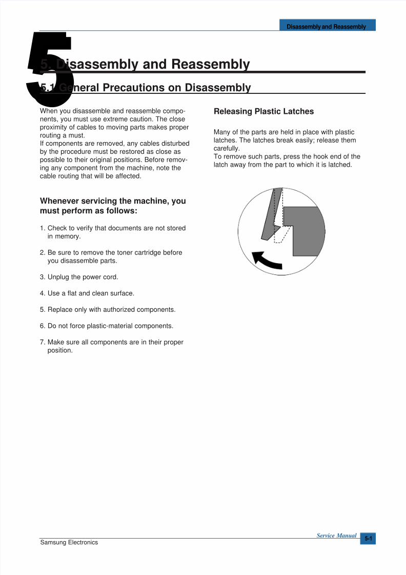
Releasing Plastic Latches
Many of the parts are held in place with plasticlatches. The latches break easily; release themcarefully.To remove such parts, press the hook end of thelatch away from the part to which it is latched.

8/4/2019 Fuser Replace
http://slidepdf.com/reader/full/fuser-replace 2/36
Samsung ElectronicsService Manual
Disassembly and Reassembly
5-2
5.2 Cover Upper (Left, Right)
1. Open the ADF Ass'y.
2. Apply light pressure to the left side of the Cover UpperLeft and pull it in the direction of arrow, as shownbelow.
3. Apply light pressure to the right side of the CoverUpper Right and pull it in the direction of arrow, asshown below.
ADF Ass'y
1
2
Cover Upper Right
2
1
Cover Upper Left

8/4/2019 Fuser Replace
http://slidepdf.com/reader/full/fuser-replace 3/36
Disassembly and Reassembly
Samsung ElectronicsService Manual
5-3
5.3 Front Cover
1. Take out the Cassette.
2. Open the Cover.
3. If necessary, remove the Toner Cartridge.
4. To remove the Front Cover, first pull the part below theboth side of the Front Cover with a light pressure tothe direction of arrow.
Cassette
Toner Cartridge
Front Cover
2
1
8/4/2019 Fuser Replace
http://slidepdf.com/reader/full/fuser-replace 4/36
Samsung ElectronicsService Manual
Disassembly and Reassembly
5-4
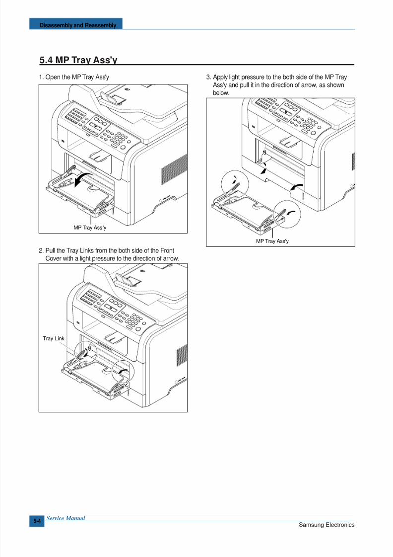
5.4 MP Tray Ass'y
1. Open the MP Tray Ass'y
2. Pull the Tray Links from the both side of the FrontCover with a light pressure to the direction of arrow.
3. Apply light pressure to the both side of the MP TrayAss'y and pull it in the direction of arrow, as shownbelow.
MP Tray Ass'y
MP Tray Ass'y
Tray Link

8/4/2019 Fuser Replace
http://slidepdf.com/reader/full/fuser-replace 5/36
Disassembly and Reassembly
Samsung ElectronicsService Manual
5-5
5.5 Rear Cover
1. Take out the Duplex Unit.
2. Remove the four screws securing the Rear Cover andthen Release the Rear Cover from the Set.
3. To remove the Face Up Cover, first release theStopper Strap in the direction of arrow.
4. Unlatch the Face Up Cover from the Rear Cover andthen release the Face Up Cover, as shown below.
Duplex Unit
Stopper Strap
1 2
Rear Cover
Face Up Cover

8/4/2019 Fuser Replace
http://slidepdf.com/reader/full/fuser-replace 6/36
Samsung ElectronicsService Manual
Disassembly and Reassembly
5-6
1. Before you remove the Fuser Ass'y, you should openthe face up cover and open the guide output fuser.- Rear Cover (Refer to 5.5)
2. Remove the four screws securing the Fuser Ass'y andthen pull the Fuser Ass'y.
3. Release the CON Harness and REC Harness fromthe Thermostat and then remove the three screwssecuring the Thermostat and remove it.
4. To remove the Electrodes, first release REC Harnessfrom the left side of the Electrode and then release theCON Harness from the right side of the Electrode, asshown below.
5. Remove the two screws securing the both side of theElectrode and then release the Caps and Electrodes
in the direction of arrow, as shown below.
5.6 Fuser Ass'y
Fuser Ass'y
CON Harness
REC Harness
Electrode
Cap
Electrode
Cap
Thermostat
CON Harness
REC Harness

8/4/2019 Fuser Replace
http://slidepdf.com/reader/full/fuser-replace 7/36
Disassembly and Reassembly
Samsung ElectronicsService Manual
5-7
6. Remove the two screws securing the Input Guide andremove it.
7. Unplug the connector from the Input Guide andremove the one screw securing the Thermistor andremove it.
8. Remove the three screws securing the Idle GearBracket and remove it.
9. Remove the three screw securing the Fuser Coverand release the Fuser Cover from the Fuser Frame.
Input Guide
Idle Gear Bracket
Thermister
Fuser Cover
Fuser Frame

8/4/2019 Fuser Replace
http://slidepdf.com/reader/full/fuser-replace 8/36
Samsung ElectronicsService Manual
Disassembly and Reassembly
5-8
10. Release the HR Bush and then remove the HeatRoller, as shown below.
Notice: Be careful not to damage or contaminate thesurface of the roller when assembling and disassembling the Heat Roller.
11. To remove the Guide Input, first unlatch the Hookand then release the Guide Input in the direction ofarrow, as shown below.
Notice : You must remove the Guide Input beforeremoving the Jam Holder so that you won'tdamaged Pressure Roller.
12. Remove the Jam Link Lever (L,R) and Jam Holder(L,R) and then remove the Pressure Roller, asshown below.
Heat Roller
HR Bush
HR Bush
Hook
1
2
Guide Input
Jam Holder
Jam Link Lever
Jam Holder
Jam Link Lever
8/4/2019 Fuser Replace
http://slidepdf.com/reader/full/fuser-replace 9/36
Disassembly and Reassembly
Samsung ElectronicsService Manual
5-9
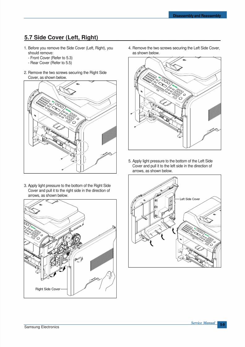
1. Before you remove the Side Cover (Left, Right), youshould remove:- Front Cover (Refer to 5.3)- Rear Cover (Refer to 5.5)
2. Remove the two screws securing the Right SideCover, as shown below.
3. Apply light pressure to the bottom of the Right SideCover and pull it to the right side in the direction ofarrows, as shown below.
4. Remove the two screws securing the Left Side Cover,as shown below.
5. Apply light pressure to the bottom of the Left SideCover and pull it to the left side in the direction ofarrows, as shown below.
5.7 Side Cover (Left, Right)
Left Side Cover
Right Side Cover
8/4/2019 Fuser Replace
http://slidepdf.com/reader/full/fuser-replace 10/36
Samsung ElectronicsService Manual
Disassembly and Reassembly
5-10
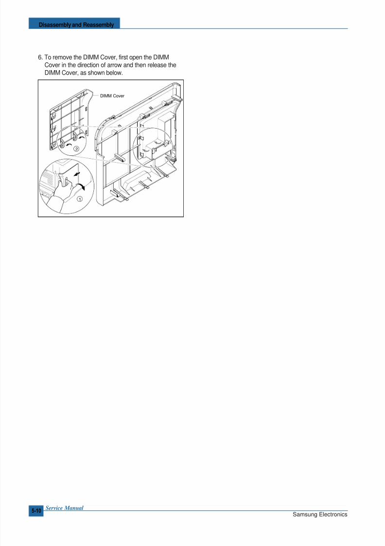
6. To remove the DIMM Cover, first open the DIMMCover in the direction of arrow and then release theDIMM Cover, as shown below.
DIMM Cover
2
1

8/4/2019 Fuser Replace
http://slidepdf.com/reader/full/fuser-replace 11/36
Disassembly and Reassembly
Samsung ElectronicsService Manual
5-11
5.8 OPE Unit
1. Before you remove the OPE Unit, you should remove:- Cover Upper L, R (Refer to 5.2)
2. Remove the two screws securing the OPE Unit to thePlaten Ass'y.
3. Apply light pressure to the front of the OPE Unit and
pull it in the direction of arrow, as shown below.
4. Unplug the three connectors from the OPE PBA, asshown below.
5. Remove the nine screws securing the OPE PBA tothe OPE Cover.
LCD
Cover
OPE PBA
OPE Cover
OPE Unit

8/4/2019 Fuser Replace
http://slidepdf.com/reader/full/fuser-replace 12/36
Samsung ElectronicsService Manual
Disassembly and Reassembly
5-12
6. Remove the Contact Rubbers from the OPE Cover.
7. Remove the Lens and Keys from the OPE Cover.
8. If necessary, remove the NEVI Cover.
9. For easy disassembly, release the Battery-NIH.
LED Lens
Onetouch
FAX
Menu
Mode
Copy
Tel
On HookStart Black
Stop ClearBlack
Battery-NIH
Onetouch
Menu
Tel_Copy
Mode
NEVI Cover
Sheet
Label
8/4/2019 Fuser Replace
http://slidepdf.com/reader/full/fuser-replace 13/36
Disassembly and Reassembly
Samsung ElectronicsService Manual
5-13
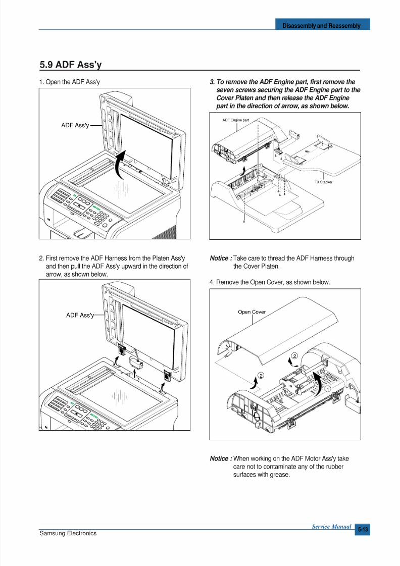
1. Open the ADF Ass'y
2. First remove the ADF Harness from the Platen Ass'yand then pull the ADF Ass'y upward in the direction ofarrow, as shown below.
3. To remove the ADF Engine part, first remove the seven screws securing the ADF Engine part to the
Cover Platen and then release the ADF Engine part in the direction of arrow, as shown below.
Notice : Take care to thread the ADF Harness throughthe Cover Platen.
4. Remove the Open Cover, as shown below.
Notice : When working on the ADF Motor Ass'y takecare not to contaminate any of the rubbersurfaces with grease.
5.9 ADF Ass'y
ADF Ass'yADF Engine part
TX Stacker
Open Cover
1
2
2
ADF Ass'y
8/4/2019 Fuser Replace
http://slidepdf.com/reader/full/fuser-replace 14/36
Samsung ElectronicsService Manual
Disassembly and Reassembly
5-14
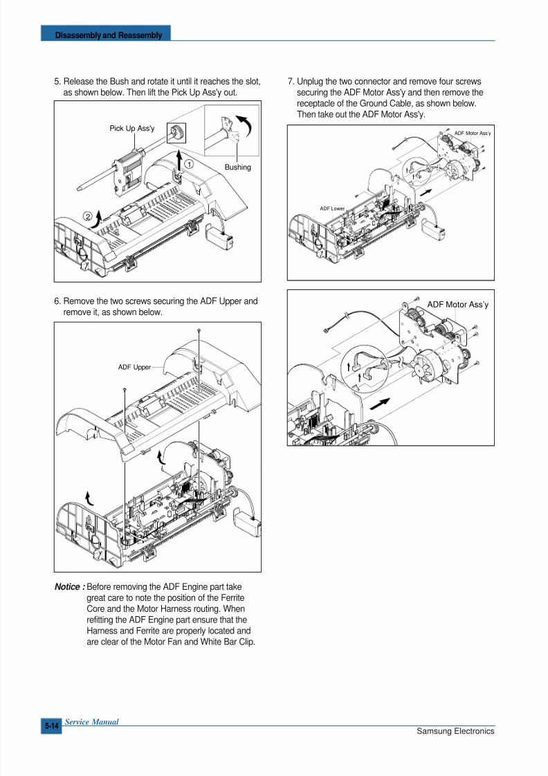
5. Release the Bush and rotate it until it reaches the slot,as shown below. Then lift the Pick Up Ass'y out.
6. Remove the two screws securing the ADF Upper andremove it, as shown below.
Notice : Before removing the ADF Engine part takegreat care to note the position of the FerriteCore and the Motor Harness routing. Whenrefitting the ADF Engine part ensure that theHarness and Ferrite are properly located andare clear of the Motor Fan and White Bar Clip.
7. Unplug the two connector and remove four screwssecuring the ADF Motor Ass'y and then remove thereceptacle of the Ground Cable, as shown below.Then take out the ADF Motor Ass'y.
ADF Motor Ass’y
ADF Lower
ADF Motor Ass’y
Pick Up Ass'y
Bushing
2
1
ADF Upper

8/4/2019 Fuser Replace
http://slidepdf.com/reader/full/fuser-replace 15/36
Disassembly and Reassembly
Samsung ElectronicsService Manual
5-15
1. Before you remove the Platen Ass'y, you shouldremove:
- Side Cover Left, Right (Refer to 5.7)- OPE Unit (Refer to 5.8)- ADF Ass'y (Refer to 5.9)
2. Remove the two screws securing the Platen Ass'y, asshown below.
3. Remove the one screw securing the Ground Cableand unplug the four connectors and CCD Cable.
4. Lift the Platen Ass'y in the direction of arrow, as shownbelow.
5. Remove the four screws securing the Scan Upper.
5.10 Platen Ass'y
Platen Ass'y
ADF Ground
Cable

8/4/2019 Fuser Replace
http://slidepdf.com/reader/full/fuser-replace 16/36
Samsung ElectronicsService Manual
Disassembly and Reassembly
5-16
6. Release the six hooks securing the Scan Upper to theScan Lower and remove it, as shown below.
7. Remove the CCD Cable, as shown below.
Notice: You should connector remove the CCD Cable
vertically to avoid the CCD Cable pin damage.
8. Pull up the CCD Shaft and take out the CCDM.
9. Squeeze the spring to release the tension in the Beltand lift from the pulleys, as shown below.
Scan Upper
Scan Lower
CCD Cable
Core
CCDM
CCD Shaft
BeltSpring

8/4/2019 Fuser Replace
http://slidepdf.com/reader/full/fuser-replace 17/36
Disassembly and Reassembly
Samsung ElectronicsService Manual
5-17
10. Remove the three screws securing the Scan MotorAss'y and remove it.
11. If necessary, remove the two screws securing theScan Motor and remove it, as shown below.
12. To remove the ADF Lower Harness, first unlatch theHooks in the direction of arrow and then carefullyrelease the ADF Lower Harness from the ScanLower, as shown below.
13. Unplug the connector from the Open Sensor Ass'y.
Scan Motor Ass'y
Scan Motor
Gear Bracket Ass’y
ADF Lower Harness
1
2
1

8/4/2019 Fuser Replace
http://slidepdf.com/reader/full/fuser-replace 18/36
Samsung ElectronicsService Manual
Disassembly and Reassembly
5-18
14. Unlatch the Open Sensor and remove it, as shownbelow.
15. Remove the CCD Holder.
16. Unplug the Harness from the CCD Home Sensorand release the CCD Home Sensor, as shownbelow.
Caution : Reassembling CCDM1) When refitting the Scanner Belt and Belt
Spring take care to relocate the tensionspring as close to the right side of theCCDM as is possible, as shown below.
2) When refitting the Scan Upper Cover takecare to ensure that the Cover Open Switchis not trapped.
Sensor Lever
Open Sensor
CCD Holder
CCD Home Sensor
Harness

8/4/2019 Fuser Replace
http://slidepdf.com/reader/full/fuser-replace 19/36
Disassembly and Reassembly
Samsung ElectronicsService Manual
5-19
1. Before you remove the Shield Controller Ass'y, youshould remove:- Side Cover Left (Refer to 5.7.4)
2. Unplug the all connectors and remove the one screwsecuring the Ground Cable.
3. Remove the five screws securing the Shield ControllerAss'y and remove it.
4. Remove the five screws securing the Main PBA to theShield and unplug the Film Cable and then removethe Main PBA.
5. The connectors are located, as shown below.
5.11 Shield Controller Ass'y
Shield Controller Ass’y
Shield
Film Cable
Main PBA
ADF Flat Motor
Flat Cover CCD
OPE Panel
USB Host
Cartridge
USB
Port
Modem PBA
Duplex Motor
Engine
BLDG
Pick Up
REGI
LSU_5V
LSU
MPF_SEN
MPF
Thermistor
Network
Port
Parallel
Port
SCF Con

8/4/2019 Fuser Replace
http://slidepdf.com/reader/full/fuser-replace 20/36
Samsung ElectronicsService Manual
Disassembly and Reassembly
5-20
6. Remove the three screws securing the Modem PBAto the Shield and unplug the Film Cable and thenremove the Modem PBA.
7. Remove the two screws securing the Speaker to theShield and unplug the connector from the ModemPBA and then remove the Speaker.
Modem PBA
Shield
Film Cable
Shield
Speaker
8/4/2019 Fuser Replace
http://slidepdf.com/reader/full/fuser-replace 21/36
Disassembly and Reassembly
Samsung ElectronicsService Manual
5-21
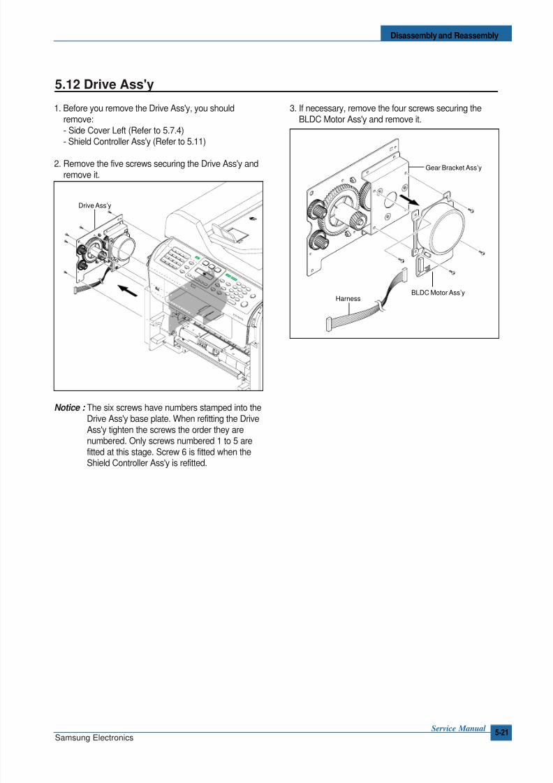
1. Before you remove the Drive Ass'y, you shouldremove:- Side Cover Left (Refer to 5.7.4)- Shield Controller Ass'y (Refer to 5.11)
2. Remove the five screws securing the Drive Ass'y andremove it.
Notice : The six screws have numbers stamped into theDrive Ass'y base plate. When refitting the DriveAss'y tighten the screws the order they arenumbered. Only screws numbered 1 to 5 arefitted at this stage. Screw 6 is fitted when theShield Controller Ass'y is refitted.
3. If necessary, remove the four screws securing theBLDC Motor Ass'y and remove it.
5.12 Drive Ass'y
Drive Ass’y
Gear Bracket Ass’y
BLDC Motor Ass’yHarness

8/4/2019 Fuser Replace
http://slidepdf.com/reader/full/fuser-replace 22/36
Samsung ElectronicsService Manual
Disassembly and Reassembly
5-22
5.13 Duplex Drive Ass'y
1. Before you remove the Duplex Drive Ass'y, you shouldremove:- Side Cover Right (Refer to 5.7.3)
2. Unplug the connector from the Connection PCB andremove the three screws securing the Duplex DriveUnit and remove it.
3. If necessary, remove the two screws securing theDuplex Motor and remove it.
Duplex Drive Ass'y
Connection
PCB
Duplex Motor
Harness
Duplex Motor
Bracket Ass’y

8/4/2019 Fuser Replace
http://slidepdf.com/reader/full/fuser-replace 23/36
Disassembly and Reassembly
Samsung ElectronicsService Manual
5-23
5.14 Shield SMPS Ass'y
1. Before you remove the Shield SMPS Ass'y, youshould remove:- Side Cover Right (Refer to 5.7.3)- Duplex Drive Ass'y (Refer to 5.13)
2. Unplug the two connectors (HVPS, Fuser).
3. Remove the three screws securing the Shield SMPSAss'y and remove it.
4. Unplug the connector (AC Inlet) and remove the fourscrews securing SMPS and remove it.
HVPS Connector
Fuser Connector
Shield SMPS Ass’y
SMPS
Insulator Sheet
Shield SMPS (With AC Inlet)
AC Inlet Connector
8/4/2019 Fuser Replace
http://slidepdf.com/reader/full/fuser-replace 24/36
Samsung ElectronicsService Manual
Disassembly and Reassembly
5-24
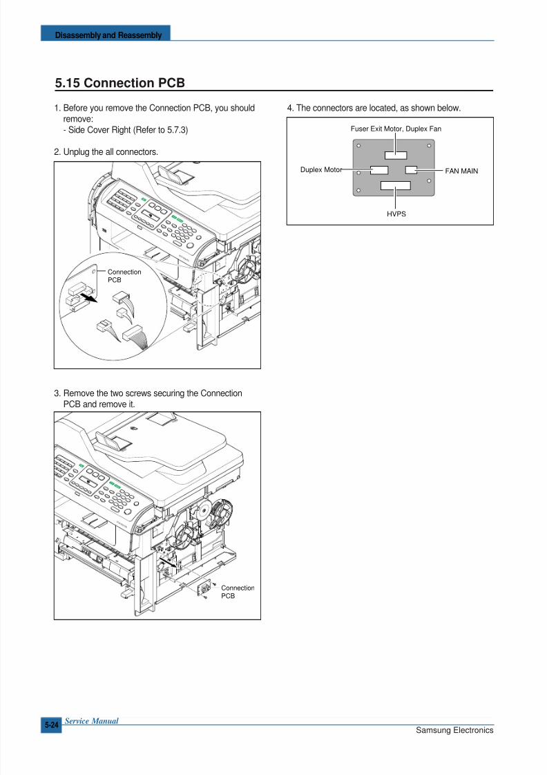
5.15 Connection PCB
1. Before you remove the Connection PCB, you shouldremove:- Side Cover Right (Refer to 5.7.3)
2. Unplug the all connectors.
3. Remove the two screws securing the Connection
PCB and remove it.
4. The connectors are located, as shown below.
ConnectionPCB
Connection
PCB
Fuser Exit Motor, Duplex Fan
FAN MAIN
HVPS
Duplex Motor

8/4/2019 Fuser Replace
http://slidepdf.com/reader/full/fuser-replace 25/36
Disassembly and Reassembly
Samsung ElectronicsService Manual
5-25
1. Before you remove the Fuser Drive Ass'y, you shouldremove:- Side Cover Right (Refer to 5.7.3)
2. Unplug the connector from the Connection PCB.
3. Remove the three screws securing the Fuser Drive
Ass'y and remove it.
4. If necnsary, remove the two screws securing the StepMotor and remove it.
Fuser Drive
ConnectionPCB
Fuser Drive Ass’y
Step Motor
Harness
Fuser Exit Bracket Ass'y
5.16 Fuser Drive Ass'y
8/4/2019 Fuser Replace
http://slidepdf.com/reader/full/fuser-replace 26/36
Samsung ElectronicsService Manual
Disassembly and Reassembly
5-26
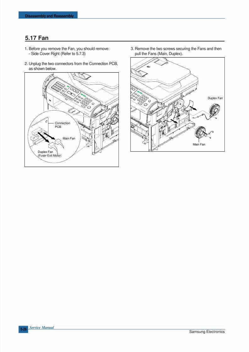
1. Before you remove the Fan, you should remove:- Side Cover Right (Refer to 5.7.3)
2. Unplug the two connectors from the Connection PCB,as shown below.
3. Remove the two screws securing the Fans and thenpull the Fans (Main, Duplex).
5.17 Fan
Main Fan
Duplex Fan
(Fuser Exit Motor)
ConnectionPCB
Duplex Fan
Main Fan
8/4/2019 Fuser Replace
http://slidepdf.com/reader/full/fuser-replace 27/36
Disassembly and Reassembly
Samsung ElectronicsService Manual
5-27
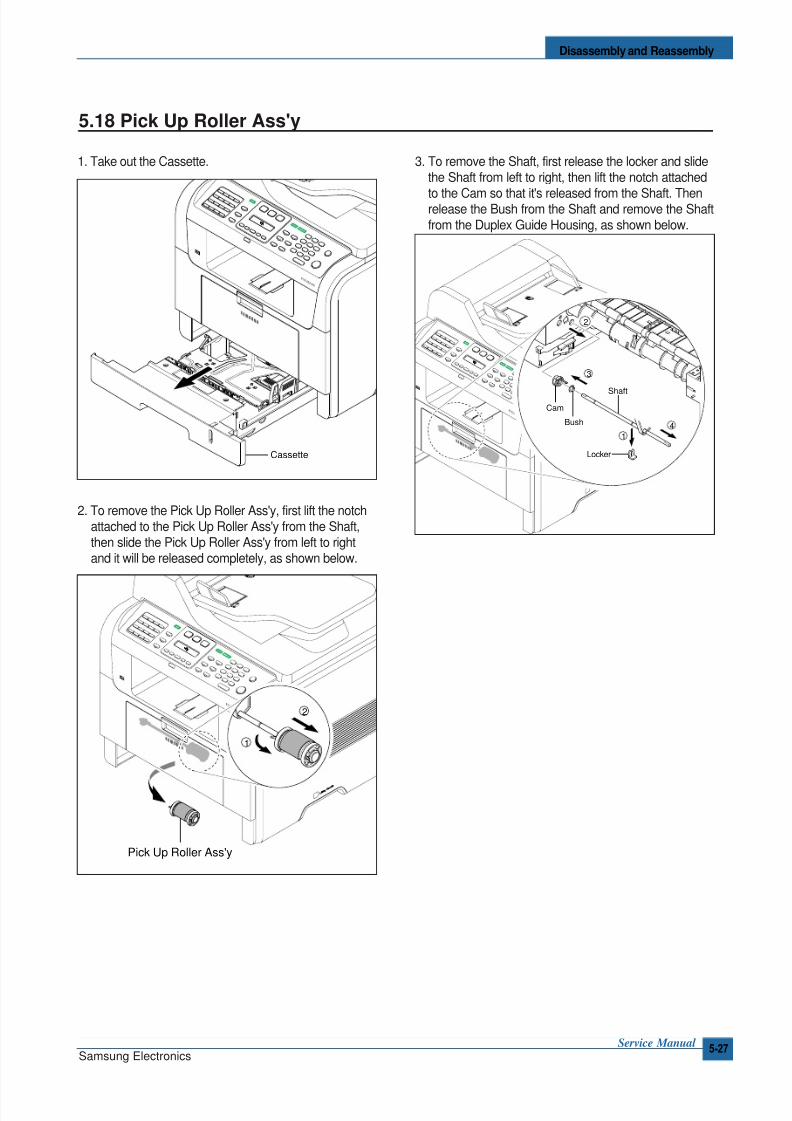
5.18 Pick Up Roller Ass'y
1. Take out the Cassette.
2. To remove the Pick Up Roller Ass'y, first lift the notchattached to the Pick Up Roller Ass'y from the Shaft,then slide the Pick Up Roller Ass'y from left to rightand it will be released completely, as shown below.
3. To remove the Shaft, first release the locker and slidethe Shaft from left to right, then lift the notch attached
to the Cam so that it's released from the Shaft. Thenrelease the Bush from the Shaft and remove the Shaftfrom the Duplex Guide Housing, as shown below.
2
1
Cam
Bush
Shaft
Locker
3
4
Cassette
Pick Up Roller Ass'y
1
2

8/4/2019 Fuser Replace
http://slidepdf.com/reader/full/fuser-replace 28/36
Samsung ElectronicsService Manual
Disassembly and Reassembly
5-28
1. Before you remove the Duplex Guide Housing, youshould remove:- Pick Up Roller Ass'y (Refer to 5.18)
2. Remove the two screws securing the Duplex GuideHousing.
3. Unplug the one connector (Photo Interrupter) andremove the Duplex Guide Housing (with Feed Roller),as shown below.
4. Pull the Feed Roller from the Bushing.
Duplex Guide Housing
Bushing
Feed Roller
5.19 Duplex Guide Housing (With Feed Roller)
Photo Interrupter
Connector
Duplex Guide Housing

8/4/2019 Fuser Replace
http://slidepdf.com/reader/full/fuser-replace 29/36
Disassembly and Reassembly
Samsung ElectronicsService Manual
5-29
5.20 HVPS Housing
1. Before you remove the HVPS Housing, you shouldremove:- Duplex Drive Ass'y (Refer to 5.13)- Unplug the HVPS Connector (Refer to 5.14)- Pick Up Roller Ass'y (Refer to 5.18)- Duplex Guide Housing (Refer to 5.19)
2. Remove the eight screws securing the HVPSHousing, as shown below.
3. Unplug the connector for connector PBAand SMPSfirst. Unplug the other Connections.
4. If necessary, remove the three screws securing theHVPS and remove it.
HVPS Housing
Duplex Motor
ConnectionPBA & SMPS
Engine
Duplex
GuideHousing
HVPS
Insulator Sheet
Shield
8/4/2019 Fuser Replace
http://slidepdf.com/reader/full/fuser-replace 30/36
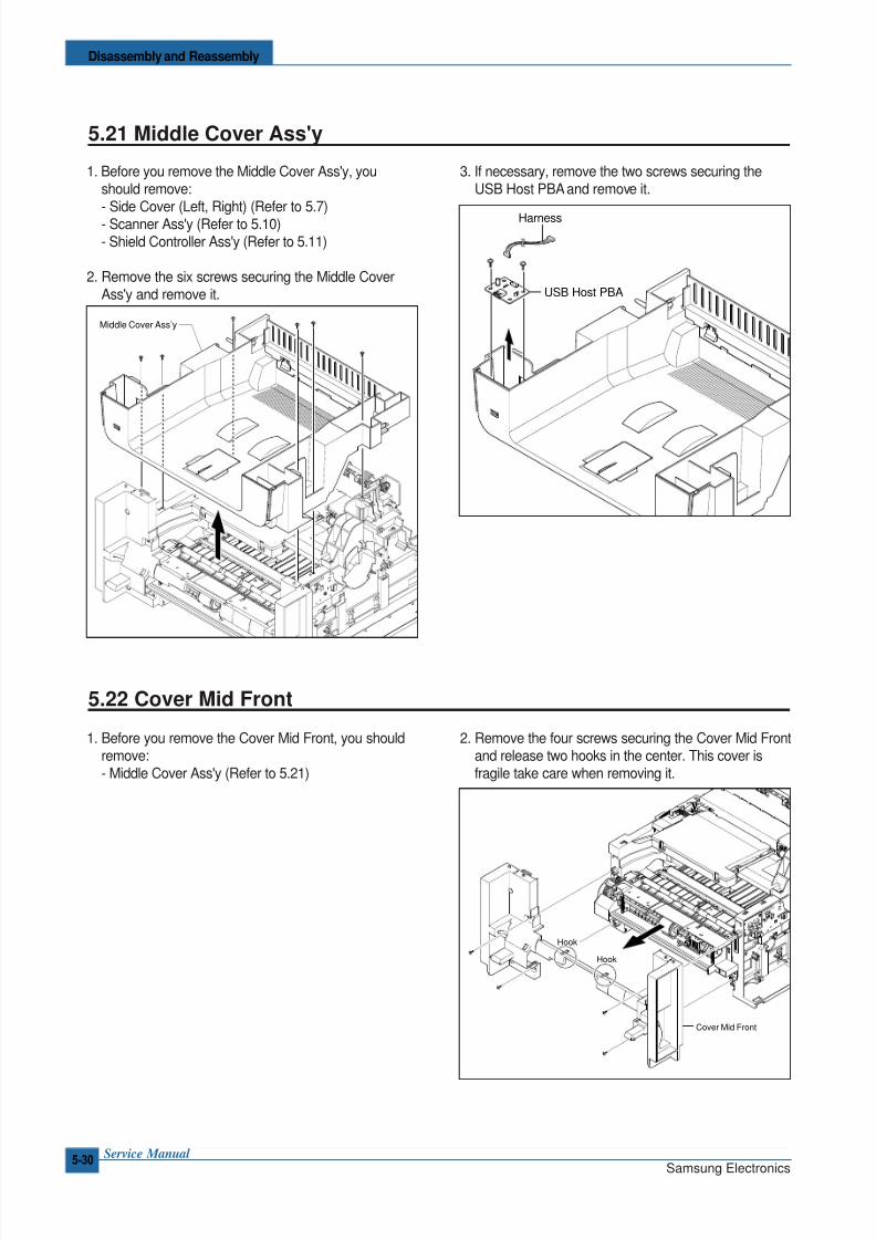
5.22 Cover Mid Front
1. Before you remove the Cover Mid Front, you shouldremove:- Middle Cover Ass'y (Refer to 5.21)
2. Remove the four screws securing the Cover Mid Frontand release two hooks in the center. This cover isfragile take care when removing it.
Cover Mid Front
Hook
Hook
Samsung ElectronicsService Manual
Disassembly and Reassembly
5-30
5.21 Middle Cover Ass'y
1. Before you remove the Middle Cover Ass'y, youshould remove:- Side Cover (Left, Right) (Refer to 5.7)- Scanner Ass'y (Refer to 5.10)- Shield Controller Ass'y (Refer to 5.11)
2. Remove the six screws securing the Middle CoverAss'y and remove it.
3. If necessary, remove the two screws securing theUSB Host PBAand remove it.
Middle Cover Ass’y
USB Host PBA
Harness

8/4/2019 Fuser Replace
http://slidepdf.com/reader/full/fuser-replace 31/36
Disassembly and Reassembly
Samsung ElectronicsService Manual
5-31
5.23 MPF Housing
1. Before you remove the MPF Housing, you shouldremove:- Cover Mid Front (Refer to 5.22)
2. Remove the four screws securing the MPF Housingand remove it.
3. To remove the MP Pick Up Ass'y, first lift the notchattached to the left side Stopper so that it's slide theright to left from the Shaft, then left side Idle slid theright to left from the Shaft and take out the MP PickUp Ass'y, as shown below.
Notice : Do not grab the rubber part of the Feed1 Roller,it may cause a malfunction due to a foreigenobject.
MPF Housing
Stopper
1
2
Idle
MP Pick Up Ass'y
MPF Housing

8/4/2019 Fuser Replace
http://slidepdf.com/reader/full/fuser-replace 32/36
Samsung ElectronicsService Manual
Disassembly and Reassembly
5-32
5.24 Feed Roller Parts
1. Before you remove the Feed Roller Parts, you shouldremove:- Pick Up Roller Ass'y (Refer to 5.18)- Duplex Guide Housing (Refer to 5.19)- Middle Cover Ass'y (Refer to 5.21)- MPF Housing (Refer to 5.23)
2. Remove the two screws securing the both side of thePlate Push Bushing and then remove the Guides.
3. Pull up the Feed Idle Shaft and the Bushs (withSpring).
4. Release the E-Ring securing the Feed2 Gear andremove it.
5. Remove the three screws securing the Feed BracketUnit and then remove the Feed Bracket Unit andFeed2 Shaft.
Plate Push Bushing
Feed Idle Shaft
Bush
Spring
Feed2 Gear
E-Ring
Feed2 Shaft
Feed Bracket Unit

8/4/2019 Fuser Replace
http://slidepdf.com/reader/full/fuser-replace 33/36
Disassembly and Reassembly
Samsung ElectronicsService Manual
5-33
6. If necessary, release the three E-Rings securing theGears (T2 Idle, Retard, Idle) and then remove theGears from the Feed Bracket, as shown below.
Notice : Be aware of the E-Rings to ensure they are notlost.
7. Remove the Clutch Unit, as shown below.
8. Pull up the Feed1 Roller from the Bushing, as shownbelow.
Notice : Do not grab the rubber part of the Feed1 Roller,it may cause a malfunction due to a foreigenobject.
T2 Idle Gear
Retard Gear
Idle Gear
E-Ring
Bracket
Feed Shaft
Feed1 Gear Ass'y
Clutch Unit
Feed1 Roller
8/4/2019 Fuser Replace
http://slidepdf.com/reader/full/fuser-replace 34/36
Samsung ElectronicsService Manual
Disassembly and Reassembly
5-34
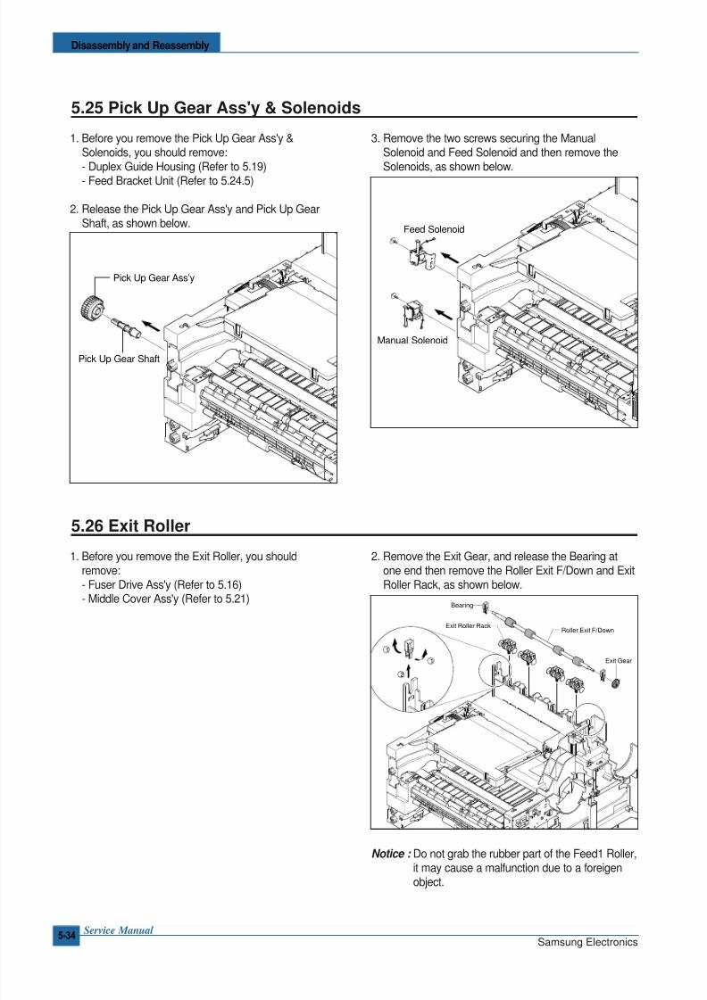
1. Before you remove the Exit Roller, you shouldremove:- Fuser Drive Ass'y (Refer to 5.16)- Middle Cover Ass'y (Refer to 5.21)
2. Remove the Exit Gear, and release the Bearing atone end then remove the Roller Exit F/Down and ExitRoller Rack, as shown below.
Notice : Do not grab the rubber part of the Feed1 Roller,it may cause a malfunction due to a foreigenobject.
5.26 Exit Roller
1
2
1
Exit Gear
Roller Exit F/DownExit Roller Rack
Bearing
1. Before you remove the Pick Up Gear Ass'y &Solenoids, you should remove:- Duplex Guide Housing (Refer to 5.19)- Feed Bracket Unit (Refer to 5.24.5)
2. Release the Pick Up Gear Ass'y and Pick Up GearShaft, as shown below.
3. Remove the two screws securing the ManualSolenoid and Feed Solenoid and then remove theSolenoids, as shown below.
Feed Solenoid
Manual Solenoid
Pick Up Gear Ass’y
Pick Up Gear Shaft
5.25 Pick Up Gear Ass'y & Solenoids

8/4/2019 Fuser Replace
http://slidepdf.com/reader/full/fuser-replace 35/36
Disassembly and Reassembly
Samsung ElectronicsService Manual
5-35
1. Before you remove the LSU, you should remove:- Middle Cover Ass'y (Refer to 5.21)
2. Remove the four screws securing the LSU andremove it.
LSU
5.27 LSU
1. Before you remove the CRUM2 PBA, you shouldremove:- Middle Cover Ass'y (Refer to 5.21)- LSU (Refer to 5.27)
2. Remove the one screw securing the CRUM2 PBAand remove it and then release the four Terminals, asshown below.
Notice : Be aware of the Terminals to ensure they are
not lost.
CRUM2 PBA
Terminal
5.28 CRUM2 PBA

8/4/2019 Fuser Replace
http://slidepdf.com/reader/full/fuser-replace 36/36
Disassembly and Reassembly
1. To remove the Transfer Roller, first pull the TR Holderand then take out the Transfer Roller, as shownbelow.
Notice : Do not grab the rubber part of the TransferRoller, it may cause a malfunction due to aforeigen object. Hole the both side of theTransfer Roller when replacing it.
TR Holder
2
1
5.29 Transfer Roller Parts