CDMA
Fundamentals of Wireless
Communications & CDMAStudent Guide
CDMA-050
80-13127-1 X6
January 24, 2000

CDMA
Copyright © 2000 QUALCOMM Incorporated. All rights reserved. Printed in the United States of America.
QUALCOMM Incorporated5775 Morehouse DriveSan Diego, CA 92121U.S.A.
Material Use RestrictionsThese written materials are to be used only in conjunction with the associated instructor-led class. They are not intended to be used solely as reference material.
No part of these written materials may be used or reproduced in any manner whatsoever without the written permission of QUALCOMM Incorporated.

Fundamentals of Wireless Communicaions & CDMA CDMA-050 Background80-13127-1 X6
QUALCOMM Proprietary 1 - 1
CDMA
Section 1
Background

Background CDMA-050 Fundamentals of Wireless Communicaions & CDMA80-13127-1 X6
1 - 2 QUALCOMM Proprietary
CDMA
Section Introduction
Figure 1-1 Section Introduction
◆ Communications History
◆ Cellular Telephony
◆ Industry Overview
◆ Analog & Digital Communications

Fundamentals of Wireless Communicaions & CDMA CDMA-050 Background80-13127-1 X6
QUALCOMM Proprietary 1 - 3
CDMA
Section Introduction
In this section the following topics will be discussed:
Communications History
Cellular Telephony
Industry Overview
Analog & Digital Communications

Background CDMA-050 Fundamentals of Wireless Communicaions & CDMA80-13127-1 X6
1 - 4 QUALCOMM Proprietary
CDMA
Section Objectives
Figure 1-2 Section Objectives
◆ Describe communication systems.
◆ List major milestones in the history of telecommunications.
◆ Describe the FCC standard for cellular and PCS spectrum.
◆ Describe analog and digital communications.

Fundamentals of Wireless Communicaions & CDMA CDMA-050 Background80-13127-1 X6
QUALCOMM Proprietary 1 - 5
CDMA
Section Objectives
The objectives of the this section are to:
Describe the parts of a communication system.
List the major milestones in the history of telecommunications.
Describe the FCC standard for the cellular and PCS spectrum.
Describe analog and digital communications.

Background CDMA-050 Fundamentals of Wireless Communicaions & CDMA80-13127-1 X6
1 - 6 QUALCOMM Proprietary
CDMA
Communication Systems
Figure 1-3 Purpose of a Communication System
Figure 1-4 Voice Communications
Deliver as much information as possible from the source to the destination (capacity issues).
Deliver information in shortest time (delay issues).
Reduce errors in delivery of information (error detection/correction issues).
Yagi, Uda

Fundamentals of Wireless Communicaions & CDMA CDMA-050 Background80-13127-1 X6
QUALCOMM Proprietary 1 - 7
CDMA
Communication Systems
Voice communications is the simplest mode of communications. People also use facial expressions and body language to communicate with each other.
Purpose of a Communication System
Deliver as much information as possible from the source to the destination (capacity issues). Information maybe of different natures, such as voice, video, or data produced by a computer.
Deliver information in shortest time (delay issues).
Reduce errors in delivery of information (error detection/correction issues).
Basic Communications System Elements
● Transmitter
● Receiver
● Medium: terrestrial (e.g. cable, coax, wire, etc.), and x-terrestrial (e.g. radio transmission)

Background CDMA-050 Fundamentals of Wireless Communicaions & CDMA80-13127-1 X6
1 - 8 QUALCOMM Proprietary
CDMA
Long Distance Communications
Figure 1-5 Telecommunications

Fundamentals of Wireless Communicaions & CDMA CDMA-050 Background80-13127-1 X6
QUALCOMM Proprietary 1 - 9
CDMA
Long Distance Communications
Tele is greek for “at a distance” or “far off”, and Communicare is latin for “to make common”.
Telecommunication is the process of long distance communications.
Early telecommunications involved smoke, flags, drums, and other such methods to relay messages and information.

Background CDMA-050 Fundamentals of Wireless Communicaions & CDMA80-13127-1 X6
1 - 10 QUALCOMM Proprietary
CDMA
Telegraph
Figure 1-6 Morse Code

Fundamentals of Wireless Communicaions & CDMA CDMA-050 Background80-13127-1 X6
QUALCOMM Proprietary 1 - 11
CDMA
Telegraph
The first wireline communications was the telegraph. Invented in the mid 19th century, it opened a new era in long-distance telecommunication.
The letters in the alphabet were encoded into patterns of short or long pulses. This technique is known as Morse Code. The electric pulses were transmitted over telegraph lines. This type of communication required the two parties to know the code. It also needed an actual physical connection between the transmitter and the receiver by wire (cables). Lack of any two elements would have made the communication impossible.

Background CDMA-050 Fundamentals of Wireless Communicaions & CDMA80-13127-1 X6
1 - 12 QUALCOMM Proprietary
CDMA
Telephone
Figure 1-7 Invention of the Telephone

Fundamentals of Wireless Communicaions & CDMA CDMA-050 Background80-13127-1 X6
QUALCOMM Proprietary 1 - 13
CDMA
Telephone
When we talk over the telephone, our voice is converted to a electronic signal by the microphone in the handset. This signal is then transmitted over telephone wires.
A telephone is a device that is capable of transmitting and receiving at the same time. Devices that can transmit and receive at the same time are called full duplex devices.

Background CDMA-050 Fundamentals of Wireless Communicaions & CDMA80-13127-1 X6
1 - 14 QUALCOMM Proprietary
CDMA
Telephone Networks
Figure 1-8 Switching and Telephone Networks
PSTN

Fundamentals of Wireless Communicaions & CDMA CDMA-050 Background80-13127-1 X6
QUALCOMM Proprietary 1 - 15
CDMA
Telephone Networks
Early Switching Devices
Switches are devices that cause a connection between two transmitting/receiving devices. The earliest switching devices were manually operated patch panels. In the late 19th century the electronic switch was developed.
Modern Switching Devices
Today many different types of automated switches are used which make it possible for fast placement of calls. A system, using DSS7 switching for instance, can make a connection between any two landline phones, in the country, in about 1 second.

Background CDMA-050 Fundamentals of Wireless Communicaions & CDMA80-13127-1 X6
1 - 16 QUALCOMM Proprietary
CDMA
Wireless Telecommunications
Figure 1-9 First Wireless Telecommunications

Fundamentals of Wireless Communicaions & CDMA CDMA-050 Background80-13127-1 X6
QUALCOMM Proprietary 1 - 17
CDMA
Wireless Telecommunications
With the invention of the radio, expensive cabling requirements were eliminated and transoceanic wireless communication became possible. Radio was invented by Marconi an Italian scientist in 1895. In radio communication the information signal is converted into an electromagnetic wave form and is broadcast in space using radiating devices known as antennas.

Background CDMA-050 Fundamentals of Wireless Communicaions & CDMA80-13127-1 X6
1 - 18 QUALCOMM Proprietary
CDMA
Terminology
Figure 1-10 Terminology
Kilo (K) = 1,000
Mega (M) = 1,000,000
Giga (G) = 1,000,000,000
milli (m) = 0.001
micro (µ) = 0.000001
nano (n) = 0.000000001

Fundamentals of Wireless Communicaions & CDMA CDMA-050 Background80-13127-1 X6
QUALCOMM Proprietary 1 - 19
CDMA
Terminology
Kilo (K) means 1,000 and is equal to 1x10³.
Mega (M) means1,000,000 and is equal to 1x10⁶
Giga (G) means 1,000,000,000 and is equal to 1x10⁹.
milli (m) means 0.001 and is equal to 1x10⁻³.
micro (µ) means 0.000001 and is equal to 1x10⁻⁶.
nano (n) means 0.000000001 and is equal to 1x10⁻⁹.

Background CDMA-050 Fundamentals of Wireless Communicaions & CDMA80-13127-1 X6
1 - 20 QUALCOMM Proprietary
CDMA
Analog and Digital Signals
Figure 1-11 Analog Signals
Figure 1-12 Digital Signals
1000011 1000100 1001101 1000001
C D M A

Fundamentals of Wireless Communicaions & CDMA CDMA-050 Background80-13127-1 X6
QUALCOMM Proprietary 1 - 21
CDMA
Analog and Digital Signals
Analog Signals
Analog signals, such as voice, have frequency and amplitude components. These two components define the characteristics of the signal A woman’s voices is much higher in frequency than a man’s. Amplitude is “how loud a person talks”.
A analog communication system employs a continuous transmission that varies in frequency and amplitude.
Digital Signals
A digital signal is a series discrete values. In binary digital systems there are only two distinct values which generally are represented by “0” and “1”. Each 0 or 1 is designated as a bit or digit.
A digital communication system can use discontinuous transmission that may vary in frequency, amplitude, phase, or polarity.

Background CDMA-050 Fundamentals of Wireless Communicaions & CDMA80-13127-1 X6
1 - 22 QUALCOMM Proprietary
CDMA
Digital and Telecommunications
Figure 1-13 Data Communications

Fundamentals of Wireless Communicaions & CDMA CDMA-050 Background80-13127-1 X6
QUALCOMM Proprietary 1 - 23
CDMA
Digital and Telecommunications
With the development of digital technology signals could be digitized and processed very fast, using fast digital machines such as micro-processor (computers). The marriage of computers and computer controlled devices paved the way for digital technology.
This new capability provides higher-quality and more reliable methods for audio, video and data transmission.

Background CDMA-050 Fundamentals of Wireless Communicaions & CDMA80-13127-1 X6
1 - 24 QUALCOMM Proprietary
CDMA
Mobile Telephones
Figure 1-14 First Mobile Telephones
PSTN

Fundamentals of Wireless Communicaions & CDMA CDMA-050 Background80-13127-1 X6
QUALCOMM Proprietary 1 - 25
CDMA
Mobile Telephones
Mobile Telephones
Unlike the traditional telephone, which requires wire connections between telephones, the mobile telephone broadcasts its signals through the air. The first wireless telephone system used a single transmission which covered a large area. Very powerful transmitters and very high antenna towers were required to cover a large area.
Advantages of Mobile Telephone
● Not restricted by the location of a telephone wall jack.
● New market opportunities.
Disadvantages of Mobile Telephone
● Phones and air time was expensive.
● Phones were big and bulky.
● Limited coverage, when the edge of the cell was reached you either stopped or dropped the call.
● Limited capacity, limited number of frequencies were available for use.
● No privacy.

Background CDMA-050 Fundamentals of Wireless Communicaions & CDMA80-13127-1 X6
1 - 26 QUALCOMM Proprietary
CDMA
Cellular Telephones
Figure 1-15 Analog Cellular Telephones

Fundamentals of Wireless Communicaions & CDMA CDMA-050 Background80-13127-1 X6
QUALCOMM Proprietary 1 - 27
CDMA
Cellular Telephones
New Wireless Service
Federal Communications Commission (FCC) provided new and more frequencies for wireless services. Tests for cellular networks were conducted in Chicago in the early 1980’s. Commercial services started shortly after the testing. New methods of control were developed which allowed for better services. This paved the way for expanded services, more service providers, and greater mobility.
Advantages
● Truly mobile communications - calls could be carried from one cell site to another.
● Full duplex operation.
● Greater capacity.
● Greater coverage.
● Greater service area.
● More service areas available.
Disadvantages
● No privacy.

Background CDMA-050 Fundamentals of Wireless Communicaions & CDMA80-13127-1 X6
1 - 28 QUALCOMM Proprietary
CDMA
Cellular Network
Figure 1-16 Cellular Network Components
PSTN
MTSO
Reverse
Forward

Fundamentals of Wireless Communicaions & CDMA CDMA-050 Background80-13127-1 X6
QUALCOMM Proprietary 1 - 29
CDMA
Cellular Network
Cellular Service
The service providers used a network of cells in a geographical area to provide service. This reduced the requirement for a high-powered transceiver and accommodated more users. With the advancement of newer technology, service, and reduced service cost the system and network capacity was quickly reached and new demands were placed on service providers.
Network Components
● Cell site - transmitter and receiver for phone connection.
● Mobile telephone switching office (MTSO) - control and operational purposes.
● Public switched telephone network (PSTN) - connection to phones located in individual homes.

Background CDMA-050 Fundamentals of Wireless Communicaions & CDMA80-13127-1 X6
1 - 30 QUALCOMM Proprietary
CDMA
Coverage in a Market
Figure 1-17 Markets and Network Coverage
City
Small Town
PSTN
MTSO

Fundamentals of Wireless Communicaions & CDMA CDMA-050 Background80-13127-1 X6
QUALCOMM Proprietary 1 - 31
CDMA
Coverage in a Market
Cellular Markets
Markets are a geographical area designated by the FCC where a service provider could deploy a network and provide service. One or more networks would be deployed, by a service provider, to provide adequate coverage and capacity in a market.

Background CDMA-050 Fundamentals of Wireless Communicaions & CDMA80-13127-1 X6
1 - 32 QUALCOMM Proprietary
CDMA
Cellular Carriers and Markets
Table 1-1 Cellular Spectrum
Figure 1-18 Cellular Carriers
FrequencyBand
Carriers / Market No. ofChannels
ChannelWidth
Rev / Fwd LinkSeparation
800 MHz A = 12.5 MHzB = 12.5 MHz
A = 416B = 416
30 KHz 45 MHz
A B
991-1023
1 - 333 334 - 666 667-716
717-799
A’A” B’
10 MHz 1.5 MHz1 MHz
2.5 MHz10 MHz

Fundamentals of Wireless Communicaions & CDMA CDMA-050 Background80-13127-1 X6
QUALCOMM Proprietary 1 - 33
CDMA
Cellular Carriers and Markets
Cellular Spectrum
There is 50 MHz of band allocated for cellular operation in the 800 MHz band. There is 25 MHz used for reverse link transmission and the remaining 25 MHz is used for forward link transmission.
Each link is divided into 832 channels. The separation between each channel is 30 KHz. The channels are used in pairs so for any given reverse link channel there will be a corresponding forward link channel.
Cellular Carriers
The FCC allocated 2 different service providers in a market. Each carrier is allocated 12.5 MHz on the reverse link and 12.5 MHz on the forward link. A market is called a cellular geographical service area (CGSA).
Non-wireline service providers were designate as “A” carriers. The “A” carriers were companies that had no affiliation with companies providing phone service to homes in the market.
Wireline service providers were designated “B” carriers. The companies were affiliated with companies providing phone service to homes in the market.

Background CDMA-050 Fundamentals of Wireless Communicaions & CDMA80-13127-1 X6
1 - 34 QUALCOMM Proprietary
CDMA
PCS Carriers and Markets
Table 1-2 PCS Spectrum
Figure 1-19 PCS Carriers
FrequencyBand
Carriers / Market No. ofChannels
ChannelWidth
Rev / Fwd LinkSeparation
1900 MHz A, B, & C = 15 MHz ea.D, E, & F = 5 MHz ea.
A, B, & C = 300 eaD, E, & F = 100 ea
50 KHz 80 MHz
300 -399
900 - 11990 - 299 400 - 699 700 -799
800 -899
A D B
15 MHz 5 MHz 15 MHz 5 MHz 5 MHz 15 MHz
E F C

Fundamentals of Wireless Communicaions & CDMA CDMA-050 Background80-13127-1 X6
QUALCOMM Proprietary 1 - 35
CDMA
PCS Carriers and Markets
In 1995 the FCC allocated and auctioned new frequency spectrum to service providers to use in deploying new wireless communications networks. The new spectrum was for use of personal communication services or PCS. The PCS spectrum is structured for digital wireless communications.
PCS Spectrum
There is 120 MHz of band allocated for PCS operation in the 1900 MHz band. There is 60 MHz used for reverse link transmission and the remaining 60 MHz is used for forward link transmission.
The PCS spectrum is divided into 1200 frequencies designated as channels. The separation between each channel is 50 KHz. The channels are used in pairs so for any given reverse link channel there will be a corresponding forward link channel.
PCS Carriers
The FCC allocated 6 service providers in a market. Markets maybe called a major trading area (MTA) or a basic trading area (BTA).
The “A”, “B”, and “C” carriers are each allocated 15 MHz of spectrum on the reverse link and 15 MHz on the forward link.
The “D”, “E”, and “F” carriers are each allocated 5 MHz of spectrum on the reverse link and 5 MHz on the forward link.

Background CDMA-050 Fundamentals of Wireless Communicaions & CDMA80-13127-1 X6
1 - 36 QUALCOMM Proprietary
CDMA
Analog Speech Signals
Figure 1-20 Voice signal
about 200 milliseconds

Fundamentals of Wireless Communicaions & CDMA CDMA-050 Background80-13127-1 X6
QUALCOMM Proprietary 1 - 37
CDMA
Analog Speech Signals
Voice is an analog signal. Analysis show that in an average two way conversation, a person is talking about 40% of the time. The remainder of the conversation is made of pauses in a speech and the time spent on listening to the other party.
Most human speech is contained between 300 to 3.3 KHz while the human ear can hear frequencies up to 20 KHz.

Background CDMA-050 Fundamentals of Wireless Communicaions & CDMA80-13127-1 X6
1 - 38 QUALCOMM Proprietary
CDMA
Analog to Digital Conversion
Figure 1-21 A/D Conversion
Time Interval: T1 T2 T3 T4 T5 T6Digital Values: 00 01 01 00 10 11
0001
1011
time
level
T1 T2 T3
T5 T6
T4

Fundamentals of Wireless Communicaions & CDMA CDMA-050 Background80-13127-1 X6
QUALCOMM Proprietary 1 - 39
CDMA
Analog to Digital Conversion
Analog to Digital Conversion (A/D)
● Sampling - The amplitude of a voice signal is measured at regular time intervals.
● Quantization - A digital value is given to each discrete amplitudes level.
Accuracy is dependent on the number of discrete levels and the number of samples.
Pulse Code Modulation (PCM)
PCM is the most common method used to convert a voice signal into a digital signal. This process is used by telephone service providers throughout the world.

Background CDMA-050 Fundamentals of Wireless Communicaions & CDMA80-13127-1 X6
1 - 40 QUALCOMM Proprietary
CDMA
Digital to Analog Conversion
Figure 1-22 D/A Conversion
T1 T2 T3
T5 T6
T4time
0001
1011
level
Actual Waveform
Reproduced Waveform
Time Interval: T1 T2 T3 T4 T5 T6Digital Values: 00 01 01 00 10 11

Fundamentals of Wireless Communicaions & CDMA CDMA-050 Background80-13127-1 X6
QUALCOMM Proprietary 1 - 41
CDMA
Digital to Analog Conversion
Digital to Analog Conversion (D/A)
The original analog signal can be reconstructed using the digital samples. The quality of the sound is dependent on the A/D conversion device used.

Background CDMA-050 Fundamentals of Wireless Communicaions & CDMA80-13127-1 X6
1 - 42 QUALCOMM Proprietary
CDMA
Transmission of Digital Signals
Figure 1-23 Data Over the Air
0 01 1 1

Fundamentals of Wireless Communicaions & CDMA CDMA-050 Background80-13127-1 X6
QUALCOMM Proprietary 1 - 43
CDMA
Transmission of Digital Signals
Digital information is not transmitted over the air. It must be converted to a signal that will carry the digital information. Radio Frequency signals (RF) are used to send the digital information. An RF signal may carry the information in either the phase or the frequency.
Phase
The digital information can be used to change the phase of the RF signal. A digital “1” is represented by one phase while a digital “0” is represented by another phase.
Frequency
The digital information can be used to change the frequency of the RF signal. A digital “1” is represented by one frequency while a digital “0” is represented by another frequency.

Background CDMA-050 Fundamentals of Wireless Communicaions & CDMA80-13127-1 X6
1 - 44 QUALCOMM Proprietary
CDMA
Advantages of Digital
Figure 1-24 Digital Advantages
DigitalDuck
Analog Artifact
Noise Reduction
Digital Signal Processing (DSP)
Coding Capability
Ease of Implementation

Fundamentals of Wireless Communicaions & CDMA CDMA-050 Background80-13127-1 X6
QUALCOMM Proprietary 1 - 45
CDMA
Advantages of Digital
Noise Reduction
● Digital signals are more immune to noise than analog signals.
DSP Techniques
● Digital signal processing (DSP) can be used to increase the speed of the information that is sent.
● The signal can be conditioned so the information can be less distorted during transmission.
Coding Capability
● Signals can be encrypted for more privacy.
● Errors in a transmission can be detected and/or corrected.
Ease of Implementation
● Digital components are smaller than analog devices.
● Digital devices are cheaper and easily designed.
● Digital signals can be easily stored and recovered upon demand.

Background CDMA-050 Fundamentals of Wireless Communicaions & CDMA80-13127-1 X6
1 - 46 QUALCOMM Proprietary
CDMA
Section Summary
Figure 1-25 Section Summary
◆ Communications History
◆ Cellular Telephony
◆ Industry Overview
◆ Analog & Digital Communications

Fundamentals of Wireless Communicaions & CDMA CDMA-050 Background80-13127-1 X6
QUALCOMM Proprietary 1 - 47
CDMA
Section Summary
Describe the parts of a communication system.
List the major milestones in telecommunications history.
Describe the FCC standard for the cellular and PCS spectrum.
Describe analog and digital communications.

Background CDMA-050 Fundamentals of Wireless Communicaions & CDMA80-13127-1 X6
1 - 48 QUALCOMM Proprietary
CDMA
Comments/Notes

Fundamentals of Wireless Communicaions & CDMA CDMA-050 The Cellular System80-13127-1 X6
QUALCOMM Proprietary 2 - 1
CDMA
Section 2
The Cellular System

The Cellular System CDMA-050 Fundamentals of Wireless Communicaions & CDMA80-13127-1 X6
2 - 2 QUALCOMM Proprietary
CDMA
Section Introduction
Figure 2-1 Section Introduction
◆ Cellular Architecture
◆ CDMA Equipment
◆ Types of Calls

Fundamentals of Wireless Communicaions & CDMA CDMA-050 The Cellular System80-13127-1 X6
QUALCOMM Proprietary 2 - 3
CDMA
Section Introduction
In this section the following topics will be discussed:
Cellular Architecture
CDMA Equipment
Types of Calls
The Cellular System CDMA-050 Fundamentals of Wireless Communicaions & CDMA80-13127-1 X6
2 - 4 QUALCOMM Proprietary
CDMA
Section Objectives
Figure 2-2 Section Objectives
◆ List the components of a cellular network.
◆ List the CDMA infrasturcture hardware.
◆ Describe the types of calls in a cellular system.

Fundamentals of Wireless Communicaions & CDMA CDMA-050 The Cellular System80-13127-1 X6
QUALCOMM Proprietary 2 - 5
CDMA
Section Objectives
The objectives of the this section are to:
List the components of a cellular network.
List the CDMA infrastructure hardware.
Describe the types of calls in a cellular system.

The Cellular System CDMA-050 Fundamentals of Wireless Communicaions & CDMA80-13127-1 X6
2 - 6 QUALCOMM Proprietary
CDMA
Network Components
Figure 2-3 Basic Digital Architecture
PSTN
BSC
BTS
BTS
BTS

Fundamentals of Wireless Communicaions & CDMA CDMA-050 The Cellular System80-13127-1 X6
QUALCOMM Proprietary 2 - 7
CDMA
Network Components
A digital wireless system has 4 basic components:
● Mobile phones (personal station (PS), mobile station (MS), portable, subscriber, user terminal (UT), handheld, or mobile)
● Base Station Transceiver Subsystem (BTS), Base Station (BS), or cell site.
● Base Station Controller (BSC), Mobile Switching Center (MSC), Mobile Telephone Switching Office (MTSO), or switch.
● Public switched telephone network (PSTN).

The Cellular System CDMA-050 Fundamentals of Wireless Communicaions & CDMA80-13127-1 X6
2 - 8 QUALCOMM Proprietary
CDMA
Network Interconnects
Figure 2-4 Network Interconnects
Reverse Link
BetaSector
GammaSector
AlphaSector
BSC
Forward Link
PSTN
BTS

Fundamentals of Wireless Communicaions & CDMA CDMA-050 The Cellular System80-13127-1 X6
QUALCOMM Proprietary 2 - 9
CDMA
Cellular Network Interconnects
There are 3 types of connections for connecting the network components:
● Mobile to BTS: air links (forward & reverse links)
● BTS to BSC: backhaul (T1/E1)
● BSC to PSTN: POTS (plain old telephone service) (T1/E1)

The Cellular System CDMA-050 Fundamentals of Wireless Communicaions & CDMA80-13127-1 X6
2 - 10 QUALCOMM Proprietary
CDMA
Infrastructure Equipment
Figure 2-5 QUALCOMM Infrastructure
BSC
Typical Rack
Indoor BTS
DigitalRack
RF Rack
Outdoor BTS

Fundamentals of Wireless Communicaions & CDMA CDMA-050 The Cellular System80-13127-1 X6
QUALCOMM Proprietary 2 - 11
CDMA
Infrastructure Equipment
Base Station Controller (BSC)
BSC functions:
● Call control processes.
● Database of subscribers.
● Record calls for billing.
● Switch the calls to the PSTN.
● Vocoding of the voice signal.
Base Station Transceiver System
BTS functions are:
● CDMA processing of all signals.
● Transmitting and receiving of all RF signals.
There are 2 types of BTS’ one for indoor installation and the other for outdoor installation.
BTS Sectorization
A BTS may have up to 9 sectors. Each sector operates like an independent BTS but only additional hardware is required. In CDMA the addition of sectors in a BTS further increases the capacity.

The Cellular System CDMA-050 Fundamentals of Wireless Communicaions & CDMA80-13127-1 X6
2 - 12 QUALCOMM Proprietary
CDMA
Subscriber Units
Figure 2-6 QUALCOMM Subscriber
Q Phone
QCT-1000/1200 QCP-800/1900

Fundamentals of Wireless Communicaions & CDMA CDMA-050 The Cellular System80-13127-1 X6
QUALCOMM Proprietary 2 - 13
CDMA
Subscriber Units
Names For A Phone
A wireless phone may have many names such as personal station (PS), mobile station (MS), portable, subscriber, user terminal (UT), handheld, or mobile.
Cellular or PCS Applications
● Home (wireless local loop)
● Office (wireless private branch exchange (WPBX))
● Portable

The Cellular System CDMA-050 Fundamentals of Wireless Communicaions & CDMA80-13127-1 X6
2 - 14 QUALCOMM Proprietary
CDMA
Types of Calls
Figure 2-7 Call Types
BSC #2BSC #1
PSTN

Fundamentals of Wireless Communicaions & CDMA CDMA-050 The Cellular System80-13127-1 X6
QUALCOMM Proprietary 2 - 15
CDMA
Types of Calls
Defined by point of origin and point of destination.
Mobile-to-Land (MTL)
Mobile phone -> BTS -> BSC -> PSTN -> land line phone.
Land-to-Mobile (LTM)
Land line phone -> PSTN -> BSC -> BTS -> mobile phone.
Mobile-to-Mobile (MTM)
Mobile phone -> BTS -> BSC -> BTS -> mobile phone. This is for a call to an individual in the same network.
Mobile phone -> BTS -> BSC #1 -> PSTN -> BSC #2 -> BTS -> mobile phone. This is for a call to an individual in a separate network with the same service provider or a different service provider.
Who pays?
Currently the owner of a wireless phone will always pay for air time. Long distance charges apply only when the call is placed from a wireless phone.

The Cellular System CDMA-050 Fundamentals of Wireless Communicaions & CDMA80-13127-1 X6
2 - 16 QUALCOMM Proprietary
CDMA
Section Summary
Figure 2-8 Section Summary
◆ Cellular Architecture
◆ CDMA Equipment
◆ Types of Calls

Fundamentals of Wireless Communicaions & CDMA CDMA-050 The Cellular System80-13127-1 X6
QUALCOMM Proprietary 2 - 17
CDMA
Section Summary
List the components of a cellular network.
List the CDMA infrastructure hardware.
Describe the types of calls in a cellular system.

The Cellular System CDMA-050 Fundamentals of Wireless Communicaions & CDMA80-13127-1 X6
2 - 18 QUALCOMM Proprietary
CDMA
Comments/Notes

Fundamentals of Wireless Communicaions & CDMA CDMA-050 Multiple Access Systems80-13127-1 X6
QUALCOMM Proprietary 3 - 1
CDMA
Section 3
Multiple Access Systems

Multiple Access Systems CDMA-050 Fundamentals of Wireless Communicaions & CDMA80-13127-1 X6
3 - 2 QUALCOMM Proprietary
CDMA
Section Introduction
Figure 3-1 Section Introduction
◆ Multiple Access Systems
◆ CDMA Channel Generation
◆ CDMA Channels

Fundamentals of Wireless Communicaions & CDMA CDMA-050 Multiple Access Systems80-13127-1 X6
QUALCOMM Proprietary 3 - 3
CDMA
Section Introduction
In this section the following topics will be discussed:
Multiple Access Systems
CDMA Channel Generation
CDMA Channels

Multiple Access Systems CDMA-050 Fundamentals of Wireless Communicaions & CDMA80-13127-1 X6
3 - 4 QUALCOMM Proprietary
CDMA
Section Objectives
Figure 3-2 Section Objectives
◆ List the techniques used in multiple access systems.
◆ Describe the 5 steps to generate a CDMA signal.
◆ List the pourpose for each channel in a CDMA system.

Fundamentals of Wireless Communicaions & CDMA CDMA-050 Multiple Access Systems80-13127-1 X6
QUALCOMM Proprietary 3 - 5
CDMA
Section Objectives
The objectives of the this section are to:
List the techniques used in multiple access systems.
Describe the 5 steps to generate a CDMA signal.
List the purpose for each channel in a CDMA system.

Multiple Access Systems CDMA-050 Fundamentals of Wireless Communicaions & CDMA80-13127-1 X6
3 - 6 QUALCOMM Proprietary
CDMA
Wireless Interference
Figure 3-3 Interference to a Mobile

Fundamentals of Wireless Communicaions & CDMA CDMA-050 Multiple Access Systems80-13127-1 X6
QUALCOMM Proprietary 3 - 7
CDMA
Wireless Interference
Wireless communication systems use E&M waves to transmit signals through the air. When subscribers share the same frequency they will create interference. The amount of interference depends on what technic is used to reduce the interference.
The resource: frequency
The problem: interference
The solutions: multiple access techniques

Multiple Access Systems CDMA-050 Fundamentals of Wireless Communicaions & CDMA80-13127-1 X6
3 - 8 QUALCOMM Proprietary
CDMA
Frequency Division Multiple Access
Figure 3-4 FDMA (Analog) Cocktail Party
Figure 3-5 How It Works
Frequency Channel 1
HI HI HI
Frequency Channel 2
GOO G GO

Fundamentals of Wireless Communicaions & CDMA CDMA-050 Multiple Access Systems80-13127-1 X6
QUALCOMM Proprietary 3 - 9
CDMA
Frequency Division Multiple Access
Frequency Division
Each Frequency Division Multiple Access (FDMA) subscriber is using the same medium (air) for communicating, but they are assigned a specific frequency channel. While they are using the frequency channel, no one else in that cell or neighboring cell can use the frequency channel.
FDMA Cocktail Party (analogy)
Two users have continuous access to the room. But, no one else can use the room while they are in it.

Multiple Access Systems CDMA-050 Fundamentals of Wireless Communicaions & CDMA80-13127-1 X6
3 - 10 QUALCOMM Proprietary
CDMA
Time Division Multiple Access
Figure 3-6 TDMA Cocktail Party
Figure 3-7 How it Works
HI
GO
user 2
H
user 2
I
user 1
O
user 1
G
HI
GO

Fundamentals of Wireless Communicaions & CDMA CDMA-050 Multiple Access Systems80-13127-1 X6
QUALCOMM Proprietary 3 - 11
CDMA
Time Division Multiple Access
Time Division
Time Division Multiple Access (TDMA) subscribers share a common frequency channel, but use the channel only for a short time. They are each given a time slot and allowed to transmit during that time slot only. When all of the available time slots in a given frequency are used the next user must be assigned to a time slot on another frequency.
TDMA Cocktail Party (analogy)
Subscribers have access to the same room, but only a pair of them can use the room for a short time. Then they must leave and another couple enters. Throughout the evening, the subscribers rotate usage of the room.

Multiple Access Systems CDMA-050 Fundamentals of Wireless Communicaions & CDMA80-13127-1 X6
3 - 12 QUALCOMM Proprietary
CDMA
Code Division Multiple Access (CDMA)
Figure 3-8 CDMA Cocktail Party
Figure 3-9 How it works
“Hello”“Bonjour” “Shalom”
“Buenos Dias”
“Guten Tag”
MMT98010116Ac.eps
red code
green code green code
red code
HI
GO
HG
IO
HI
GO

Fundamentals of Wireless Communicaions & CDMA CDMA-050 Multiple Access Systems80-13127-1 X6
QUALCOMM Proprietary 3 - 13
CDMA
Code Division Multiple Access
Code Division
Code Division Multiple Access subscribers share a common channel (frequency). All users are on the same frequency at the same time, they are divided however by codes.
CDMA Cocktail Party (analogy)
All subscribers are in the same room together. They can be all talking at the same time. They can be grouped together or standing across the room from each other. Unlike the other two multiple access systems, they do not have to leave the room!

Multiple Access Systems CDMA-050 Fundamentals of Wireless Communicaions & CDMA80-13127-1 X6
3 - 14 QUALCOMM Proprietary
CDMA
Technology Overview
Table 3-1 Wireless Technologies
Cellular Band PCS Band
Channel Bandwidth
Users / Sector / Channel
Standard Channel Bandwidth
Users / Sector / Channel
Standard
CDMA 1.25 MHz 22 / 14 IS-95A 1.25 MHz 22 / 14 ANSI J-STD-008
FDMA(Analog)
30 KHz 1 IS-41 N/A N/A N/A
TDMA 30 KHz 3 IS-54 30 KHz 3 IS-136
N. American
200 KHz 8 GSM

Fundamentals of Wireless Communicaions & CDMA CDMA-050 Multiple Access Systems80-13127-1 X6
QUALCOMM Proprietary 3 - 15
CDMA
Technology Overview
The technique used to separate users in a channel will determine the channel capacity.
Technologies
● FDMA (AMPS, DAMPS)
● TDMA (IS-54, IS-136, GSM)
● CDMA (IS-95, ANSI J-STD-008)
Bands
Not all technologies are used in the cellular band in the USA. This is due to the structure of the channel and requirements established by the FCC.

Multiple Access Systems CDMA-050 Fundamentals of Wireless Communicaions & CDMA80-13127-1 X6
3 - 16 QUALCOMM Proprietary
CDMA
CDMA System Block Diagram
Figure 3-10 CDMA Block Diagram
A/DConverter Vocoder
Encoder &Interleaver
Spreader
CodeGenerator
Voice
D/ARF
Antenna

Fundamentals of Wireless Communicaions & CDMA CDMA-050 Multiple Access Systems80-13127-1 X6
QUALCOMM Proprietary 3 - 17
CDMA
CDMA System Block Diagram
Steps in Generating a CDMA Signal
1. Voice is digitized (PSTN).
2. Digitized voice is vocoded (BSC).
3. Digital signal is encoded and interleaver (BTS).
4. Encoded signals are spread (channelized) (BTS).
5. The digital signal converted and transmitted as a radio signal (BTS).

Multiple Access Systems CDMA-050 Fundamentals of Wireless Communicaions & CDMA80-13127-1 X6
3 - 18 QUALCOMM Proprietary
CDMA
Vocoder (Voice Compression)
Figure 3-11 Speech Activity
Figure 3-12 Vocoder Operation
about 200 milliseconds
VOCODER 1 0 1 1 A/D
VocodedVoice
Pulse CodedModulation(PCM)

Fundamentals of Wireless Communicaions & CDMA CDMA-050 Multiple Access Systems80-13127-1 X6
QUALCOMM Proprietary 3 - 19
CDMA
Vocoder (Voice Compression)
When we talk, we pause between syllables and words. CDMA takes advantage of these pauses in speech activity.
Analog to digital conversion
The voice signal is converted to a digital signal using PCM.
Variable rate vocoder
The vocoder (Voice Coder) is used to compress the digital signal from the Codec (Code/Decode). The vocoder, used in a CDMA system, compresses the voice signal into various data rates. The data rate is dynamically determined by the users speech activity.
The vocoders are located at the BSC and in the phone.
Vocoder rates
The voice is compressed in the vocoder into either one of four rates (Full, 1/2, 1/4, or 1/8 rate). CDMA systems can use either an 8 kbps or 13 kbps vocoder.

Multiple Access Systems CDMA-050 Fundamentals of Wireless Communicaions & CDMA80-13127-1 X6
3 - 20 QUALCOMM Proprietary
CDMA
Encoding / Interleaving
Figure 3-13 Encoding Example
A B C D Bit Pattern
A A A B B B C C C D D D Encoded Symbols
Burst ErrorsA A A B ? ? ? ? C D D D
Decoded BitsA ? ? D

Fundamentals of Wireless Communicaions & CDMA CDMA-050 Multiple Access Systems80-13127-1 X6
QUALCOMM Proprietary 3 - 21
CDMA
Encoding / Interleaving
Purpose:
The purpose of the encoder is to build redundancy into the signal.
Example:
A simple coding scheme is shown in this example. The digital message consists of four bits (A,B,C,D) of vocoded data. Each of the bits is repeated (encoded) 3 times. These encoded bits are called symbols.
The encoder is located at the BTS and in the phone.
Decoding:
Decoding at the receiver uses a majority logic rule (two out of three wins). If an error occurs the redundancy can help recover the lost information.

Multiple Access Systems CDMA-050 Fundamentals of Wireless Communicaions & CDMA80-13127-1 X6
3 - 22 QUALCOMM Proprietary
CDMA
Encoding / Interleaving
Figure 3-14 Interleaving Example
A B C D
A A A B B B C C C D D D
A B C D A B C D A B C D
A ? A B ? B C ? C D ? D
Bit Pattern
Encoded Symbols
Interleaved symbols
Burst Errors
De-interleaves Symbols
Decoded BitsA B C D
A B C D ? ? ? ? A B C D

Fundamentals of Wireless Communicaions & CDMA CDMA-050 Multiple Access Systems80-13127-1 X6
QUALCOMM Proprietary 3 - 23
CDMA
Encoding / Interleaving
Purpose:
Interleaving is a simple, but powerful, method of reducing the effects of burst errors and recovering bits when burst errors occur.
Example:
In this example the symbols from each group are interleaved in a pattern that the receiver knows.
The interleaver is located at the BTS and in the phone.
Deinterleaving:
Deinterleaving at the receiver will spread any burst errors that occur during transmission and make it simpler to decode.
Multiple Access Systems CDMA-050 Fundamentals of Wireless Communicaions & CDMA80-13127-1 X6
3 - 24 QUALCOMM Proprietary
CDMA
Coding and Spreading
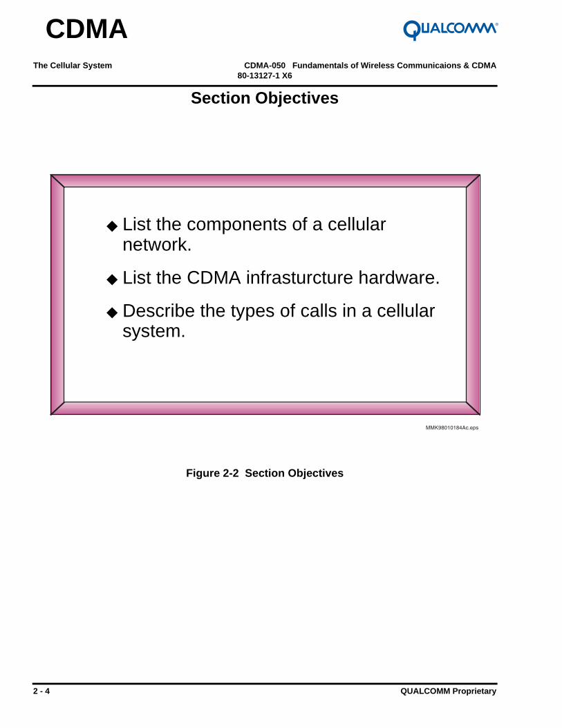
Figure 3-15 Spreading and Channelization
User 1 Data: 01
Rx
Mobile
User 1 Code: 0101
Tx
BTSUser 1 Data: 01
User 2 Data: 10
User 1 Code: 0101
User 2 Code: 0110
0 1 0 1 1 0 1 01 0 0 1 0 1 1 0

Fundamentals of Wireless Communicaions & CDMA CDMA-050 Multiple Access Systems80-13127-1 X6
QUALCOMM Proprietary 3 - 25
CDMA
Coding and Spreading
Coding & spreading
The encoded voice data is encoded using a code that will separate it from other encoded voice data. This process, known as channelization, will spread the encoded symbols over the entire bandwidth of the CDMA channel.
Transmission
The channelized data from all calls will be combined into a one signal that is transmitted is converted to an analog RF signal which is transmitted over the air.
Receiver Decoding / Despreading
The code used to channelize and spread the encoded voice data is known to the receiver. The receiver will use the code to despread/decode the signal and recover the encoded voice data.
Codes used in CDMA
Orthogonal (Walsh) codes are used on the forward link to channelize users.
Pseudorandom noise (PN) code is used on the reverse link to channelize users.

Multiple Access Systems CDMA-050 Fundamentals of Wireless Communicaions & CDMA80-13127-1 X6
3 - 26 QUALCOMM Proprietary
CDMA
Digital to Analog Conversion
Figure 3-16 Voice Recovery
VOCODER1 0 1 1 A/D
VocodedVoice
Pulse CodedDemodulation(PCM)

Fundamentals of Wireless Communicaions & CDMA CDMA-050 Multiple Access Systems80-13127-1 X6
QUALCOMM Proprietary 3 - 27
CDMA
Digital to Analog Conversion
Deinterleaving and Decoding
After the signal is despread the receiver will deinterleave and decode the signal into the original vocoded voice.
The deinterleaving and decoding is done at the BTS and in the phone.
Voice Decompression
The decompression of the voice signal is done at the BSC and then sent to the PSTN.
Voice Recovery
The receiver converts the vocoded voice into an analog voice signal.
The D/A conversion is done at the PSTN.

Multiple Access Systems CDMA-050 Fundamentals of Wireless Communicaions & CDMA80-13127-1 X6
3 - 28 QUALCOMM Proprietary
CDMA
Forward Link Channels
Figure 3-17 Forward Link Channels
Σ
Pilot
Traffic
Paging
Sync
Traffic
.
.
.

Fundamentals of Wireless Communicaions & CDMA CDMA-050 Multiple Access Systems80-13127-1 X6
QUALCOMM Proprietary 3 - 29
CDMA
Forward Link Channels
Code Channels
A channel is a stream of data designated for a specific use or person and is separated by a code. A channel may be voice data or overhead control data.
Forward Link Channels
On the forward link there are 4 channels used to transmit control and voice data to the mobile. These code channels are:
● Pilot
● Sync
● Paging
● Traffic

Multiple Access Systems CDMA-050 Fundamentals of Wireless Communicaions & CDMA80-13127-1 X6
3 - 30 QUALCOMM Proprietary
CDMA
Forward Link Channels
Figure 3-18 Pilot Channel
Figure 3-19 Sync Channel
Σ
PilotPilot
Traffic
Paging
Sync
Traffic
.
.
.
Σ
Pilot
Traffic
Sync
Paging
Sync
Traffic
.
.
.

Fundamentals of Wireless Communicaions & CDMA CDMA-050 Multiple Access Systems80-13127-1 X6
QUALCOMM Proprietary 3 - 31
CDMA
Forward Link Channels
Pilot Channel
The pilot channel is constantly transmitted. The mobile uses the pilot signal to acquire the system. After the mobile has acquired the system the pilot is used for signal strength measurement. The strength of the pilot is used to determine the power required for mobile transmit.
The pilot contains no information but the it is the strongest signal on the forward link, containing at least 20% of the total power on the forward link.
Sync Channel
The sync channel is constantly transmitted providing critical timing information to the mobile. The mobile will decode the sync channel message during the power up sequence. Once the mobile is synchronized with the base station the sync channel is ignored.

Multiple Access Systems CDMA-050 Fundamentals of Wireless Communicaions & CDMA80-13127-1 X6
3 - 32 QUALCOMM Proprietary
CDMA
Forward Link Channels
Figure 3-20 Paging Channel
Figure 3-21 Forward Traffic Channel
Σ
Pilot
Traffic
Paging
Sync
Traffic
.
.
.
Paging
Σ
Pilot
Traffic
Paging
Sync
Traffic
.
.
.
Traffic
Traffic

Fundamentals of Wireless Communicaions & CDMA CDMA-050 Multiple Access Systems80-13127-1 X6
QUALCOMM Proprietary 3 - 33
CDMA
Forward Link Channels
Paging Channel
The paging channel is used to transmit overhead information (i.e. commands and pages) to the mobile. When a call is being set up the commands and traffic channel assignment are sent on the paging channel. Once a traffic channel is established the paging channel is ignored by the mobile.
Forward Traffic Channel
The forward traffic channel is used when there is a call. Voice data and control overhead information, normally sent on the paging channel, are transmitted to the mobile on the traffic channel.

Multiple Access Systems CDMA-050 Fundamentals of Wireless Communicaions & CDMA80-13127-1 X6
3 - 34 QUALCOMM Proprietary
CDMA
Reverse Link Channels
Figure 3-22 Reverse Link Channels
Traffic
Access
Traffic
Traffic

Fundamentals of Wireless Communicaions & CDMA CDMA-050 Multiple Access Systems80-13127-1 X6
QUALCOMM Proprietary 3 - 35
CDMA
Reverse Link Channels
On the reverse link there are 2 types of channels used to transmit control and voice data to the mobile. These channels are:
● Access
● Traffic

Multiple Access Systems CDMA-050 Fundamentals of Wireless Communicaions & CDMA80-13127-1 X6
3 - 36 QUALCOMM Proprietary
CDMA
Reverse Link Channels
Figure 3-23 Access & Traffic Channel

Fundamentals of Wireless Communicaions & CDMA CDMA-050 Multiple Access Systems80-13127-1 X6
QUALCOMM Proprietary 3 - 37
CDMA
Reverse Link Code Channels
Access Channel
The access channel is used by the mobile when not assigned to a traffic channel. The access channel is used by the mobile to register with the network, originate calls, respond to pages and commands from the base station, and transmit overhead messages to the base station.
Reverse Traffic Channel
The reverse traffic channel is used when there is a call. Voice data and control overhead information, normally sent on the access channel, are transmitted to the base station on this channel.

Multiple Access Systems CDMA-050 Fundamentals of Wireless Communicaions & CDMA80-13127-1 X6
3 - 38 QUALCOMM Proprietary
CDMA
Call Processing
Figure 3-24 Call Processing
Initialization
Idle Mode
Access Mode
Traffic Mode

Fundamentals of Wireless Communicaions & CDMA CDMA-050 Multiple Access Systems80-13127-1 X6
QUALCOMM Proprietary 3 - 39
CDMA
Call Processing
Initialization Mode
● Mobile acquires system via Pilot code channel.
● Mobile synchronizes with system via Sync code channel.
Idle Mode
● Mobile and base station communicate over Access and Paging code channels when NOT involved in a call.
● Mobile obtains overhead information via the Paging code channel.
Access Mode
● Mobile accesses the network via the Access code channel
Traffic Mode
Land to mobile call
✸ When a call for a mobile is placed the mobile will receive a page on the Paging channel.
✸ The mobile responds on the Access channel and Traffic channels are established.
Mobile to land call
✸ When a call is placed from a mobile the call is placed using the Access channel.
✸ The base station responds on the Paging channel and Traffic channels are established.

Multiple Access Systems CDMA-050 Fundamentals of Wireless Communicaions & CDMA80-13127-1 X6
3 - 40 QUALCOMM Proprietary
CDMA
Roaming
Figure 3-25 Roaming

Fundamentals of Wireless Communicaions & CDMA CDMA-050 Multiple Access Systems80-13127-1 X6
QUALCOMM Proprietary 3 - 41
CDMA
Roaming
Definition
Wireless phones are programmed to operate in a specific system, called the home system. A phone operating in a non-home system is said to be a roamer.
Roaming charges
A user may be charged an additional fee for accessing the network. The fees are established by the service providers and any agreement they may have between them.

Multiple Access Systems CDMA-050 Fundamentals of Wireless Communicaions & CDMA80-13127-1 X6
3 - 42 QUALCOMM Proprietary
CDMA
Section Summary
Figure 3-26 Section Summary
◆ Multiple Access Systems
◆ CDMA Channel Generation
◆ CDMA Channels

Fundamentals of Wireless Communicaions & CDMA CDMA-050 Multiple Access Systems80-13127-1 X6
QUALCOMM Proprietary 3 - 43
CDMA
Section Summary
List the techniques used in multiple access systems.
Describe the 5 steps to generate a CDMA signal.
List the purpose for each channel in a CDMA system.

Multiple Access Systems CDMA-050 Fundamentals of Wireless Communicaions & CDMA80-13127-1 X6
3 - 44 QUALCOMM Proprietary
CDMA
Comments/Notes

Fundamentals of Wireless Communicaions & CDMA CDMA-050 Features of CDMA80-13127-1 X6
QUALCOMM Proprietary 4 - 1
CDMA
Section 4
Features of CDMA

Features of CDMA CDMA-050 Fundamentals of Wireless Communicaions & CDMA80-13127-1 X6
4 - 2 QUALCOMM Proprietary
CDMA
Section Introduction
Figure 4-1 Section Introduction
◆ Universal Frequency Reuse
◆ Power Control
◆ Soft Handoff

Fundamentals of Wireless Communicaions & CDMA CDMA-050 Features of CDMA80-13127-1 X6
QUALCOMM Proprietary 4 - 3
CDMA
Section Introduction
In this section the following topics will be discussed:
Universal Frequency Reuse
Power Control
Handoffs

Features of CDMA CDMA-050 Fundamentals of Wireless Communicaions & CDMA80-13127-1 X6
4 - 4 QUALCOMM Proprietary
CDMA
Section Objectives
Figure 4-2 Section Objectives
◆ List the features of CDMA.
◆ Describe the purpose for frequency reuse.
◆ Describe the purpose for power control.
◆ Describe the type of handoffs in CDMA.

Fundamentals of Wireless Communicaions & CDMA CDMA-050 Features of CDMA80-13127-1 X6
QUALCOMM Proprietary 4 - 5
CDMA
Section Objectives
The objectives of the this section are to:
List the features of CDMA.
Describe the purpose of Frequency reuse.
Describe the purpose for power control.
Describe the type of handoffs in CDMA.

Features of CDMA CDMA-050 Fundamentals of Wireless Communicaions & CDMA80-13127-1 X6
4 - 6 QUALCOMM Proprietary
CDMA
Frequency Planning Requirement
Figure 4-3 Cell Interference
B
AC

Fundamentals of Wireless Communicaions & CDMA CDMA-050 Features of CDMA80-13127-1 X6
QUALCOMM Proprietary 4 - 7
CDMA
Frequency Planning Requirement
Cell Interference
If cell A and B were on the same frequency in a conventional cellular systems, area C would have a frequency conflict and interference.
With the deployment of a FDMA network channel (frequency) reuse is required. In the FDMA system there is a conflict when adjacent cells use the same channel (frequency).

Features of CDMA CDMA-050 Fundamentals of Wireless Communicaions & CDMA80-13127-1 X6
4 - 8 QUALCOMM Proprietary
CDMA
FDMA & TDMA Frequency Planning
Figure 4-4 Frequency Reuse of 7
DE
F
G BC
DE
F
BC
G
DE
FC
D
E
BC
GAB
C
F
B
AA

Fundamentals of Wireless Communicaions & CDMA CDMA-050 Features of CDMA80-13127-1 X6
QUALCOMM Proprietary 4 - 9
CDMA
FDMA & TDMA Frequency Planning
Frequency Reuse of 7
To avoid conflict between cells, FDMA and TDMA systems use a reuse factor of seven (six cells surrounding each cell cannot use the same frequency). Adjacent cells will be assigned to separate channels (frequencies).
As capacity requirements increase additional cells will be added to the network creating a reworking of the frequency plan in the network.
Cell Separation
A channel (frequency) can be used again within the network but cells using the same channel must be separated by an appropriate distance.

Features of CDMA CDMA-050 Fundamentals of Wireless Communicaions & CDMA80-13127-1 X6
4 - 10 QUALCOMM Proprietary
CDMA
CDMA Frequency Planning
Figure 4-5 Universal Frequency Reuse
AA
AA
A
AA
A
AA
AA
AA
AA
A
A
A
A
A
A
A
AA
A
A
A

Fundamentals of Wireless Communicaions & CDMA CDMA-050 Features of CDMA80-13127-1 X6
QUALCOMM Proprietary 4 - 11
CDMA
CDMA Frequency Planning
CDMA Universal Frequency Reuse
CDMA has a frequency reuse of one. Each BTS in the network uses the same frequency eliminating the need for frequency planning.

Features of CDMA CDMA-050 Fundamentals of Wireless Communicaions & CDMA80-13127-1 X6
4 - 12 QUALCOMM Proprietary
CDMA
Problems in a CDMA Channel
Figure 4-6 CDMA Channel Issues

Fundamentals of Wireless Communicaions & CDMA CDMA-050 Features of CDMA80-13127-1 X6
QUALCOMM Proprietary 4 - 13
CDMA
Problems in a CDMA Channel
Near-Far Problem
If all mobiles transmitted at the same power level, signals received by the base station from mobiles further away would be weaker than those signals received from mobiles which were closer to the cell. This issue reduces, if not resolved, the capacity of a CDMA system.
Path Loss
The more distance between the cell and a phone the weaker the signal becomes.
Fading
Fading occurs when more than two signals from the same transmitter are received due to multipath.

Features of CDMA CDMA-050 Fundamentals of Wireless Communicaions & CDMA80-13127-1 X6
4 - 14 QUALCOMM Proprietary
CDMA
Reverse Link Power Control
Figure 4-7 Mobile Power Control

Fundamentals of Wireless Communicaions & CDMA CDMA-050 Features of CDMA80-13127-1 X6
QUALCOMM Proprietary 4 - 15
CDMA
Reverse Link Power Control
Power Control
The objective of power control is to ensure that signals from all mobiles are received at the Base Station with the same received power.
The CDMA network independently controls the power of each mobile.
Open Loop
Open loop is a estimate of what power the phone should use to transmit. The estimate is determined based on the strength of the mean signal power received by the mobile.
Fast Closed Loop
Fast closed loop is used when there is a call. The network will send a command to the mobile to either increase or decrease power. The command is determined on the quality of the information received at the BTS.

Features of CDMA CDMA-050 Fundamentals of Wireless Communicaions & CDMA80-13127-1 X6
4 - 16 QUALCOMM Proprietary
CDMA
Forward Link Power Control
Figure 4-8 Base Station Power Control
PSTN
BSC
BTS
BTS

Fundamentals of Wireless Communicaions & CDMA CDMA-050 Features of CDMA80-13127-1 X6
QUALCOMM Proprietary 4 - 17
CDMA
Forward Link Power Control
The BTS independently adjusts the power for each forward traffic channel based on information received from the mobile.

Features of CDMA CDMA-050 Fundamentals of Wireless Communicaions & CDMA80-13127-1 X6
4 - 18 QUALCOMM Proprietary
CDMA
Multipath
Figure 4-9 CDMA and Multipath
BSC

Fundamentals of Wireless Communicaions & CDMA CDMA-050 Features of CDMA80-13127-1 X6
QUALCOMM Proprietary 4 - 19
CDMA
Multipath
What is multipath?
Signals sent over the air can take a direct path to the mobile, bounce off objects, and arrive at the mobile’s antenna at different times. These different paths are referred to as multi-paths.
Effects of multipath signals
Multipath signals in a narrow band signal, such as FDMA and TDMA, may cause a loss of the signal through cancellation.
Multipaths in CDMA can be used to increase the quality of the signal. This is possible because CDMA is a wideband signal.
CDMA advantage
● Better voice quality.
● Reduces power requirement to maintain link.

Features of CDMA CDMA-050 Fundamentals of Wireless Communicaions & CDMA80-13127-1 X6
4 - 20 QUALCOMM Proprietary
CDMA
CDMA Receiver
Figure 4-10 Rake Receiver

Fundamentals of Wireless Communicaions & CDMA CDMA-050 Features of CDMA80-13127-1 X6
QUALCOMM Proprietary 4 - 21
CDMA
CDMA Receiver
Rake Receiver
The rake receiver is multiple receivers in one. There is a rake receiver at both the mobile and BTS. Each receiver may assigned to a received signal.

Features of CDMA CDMA-050 Fundamentals of Wireless Communicaions & CDMA80-13127-1 X6
4 - 22 QUALCOMM Proprietary
CDMA
What is a Handoff?
Figure 4-11 Handoff
Cell Cell

Fundamentals of Wireless Communicaions & CDMA CDMA-050 Features of CDMA80-13127-1 X6
QUALCOMM Proprietary 4 - 23
CDMA
What is a Handoff?
Why Handoff?
Handoffs are necessary to continue the call as the phone travels.
Handoff describes the process of transferring a call from one cell to another.
Handoff Overview
As the phone moves through a network the system controller transfers the call from one cell to another, this process is called “handoff”. Handoffs maybe done with the assistance of the mobile or the system controller will control the process by itself.

Features of CDMA CDMA-050 Fundamentals of Wireless Communicaions & CDMA80-13127-1 X6
4 - 24 QUALCOMM Proprietary
CDMA
Handoffs
Figure 4-12 Handoff Process
Cell ACell B
Cell ACell B

Fundamentals of Wireless Communicaions & CDMA CDMA-050 Features of CDMA80-13127-1 X6
QUALCOMM Proprietary 4 - 25
CDMA
Handoffs
Break-Before-Make
In a “hard” handoff, the mobile must disconnect (or break) its connection before connecting to the new cell.
As the mobile moves from one coverage area to another, the mobile will be instructed to change to the new network.
Advantages of Hard Handoff
● Continue the call beyond the current network.
● Provide expanded service.
● Reduce dropped calls.
● Overlay and integration of new CDMA networks with the existing networks.
Features of CDMA CDMA-050 Fundamentals of Wireless Communicaions & CDMA80-13127-1 X6
4 - 26 QUALCOMM Proprietary
CDMA
Types of CDMA Handoff
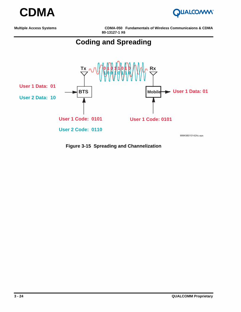
Figure 4-13 CDMA Handoffs
BSC
BTS
BTS
PSTN
MTSO BSC
PSTN

Fundamentals of Wireless Communicaions & CDMA CDMA-050 Features of CDMA80-13127-1 X6
QUALCOMM Proprietary 4 - 27
CDMA
Types of CDMA Handoff
Soft Handoffs
Soft handoffs occur when the mobile is involved in a call. CDMA uses the mobile to assist the network in the handoff. The term soft handoff is used to describe the “make-before-break” process which takes place during the handoff.
Soft handoffs occur between cells, sectors in a cell, or combination of cells and sectors.
Hard Handoffs
Hard handoffs occur when the mobile is involved in a call. During a hard handoff a CDMA phone is not able to assist the network in the handoff. The term hard handoff is used to describe the “break-before-make” process that occurs during the handoff.
Hard handoffs occur between CDMA to Analog systems.
Idle Handoff
Idle handoffs occur when the mobile is NOT involved in a call. The idle handoff does not require any interaction between the phone and the base station.
Used in CDMA mode only.

Features of CDMA CDMA-050 Fundamentals of Wireless Communicaions & CDMA80-13127-1 X6
4 - 28 QUALCOMM Proprietary
CDMA
Soft Handoff
Figure 4-14 Soft Handoff
Cell ACell B
Cell ACell B
Cell ACell B

Fundamentals of Wireless Communicaions & CDMA CDMA-050 Features of CDMA80-13127-1 X6
QUALCOMM Proprietary 4 - 29
CDMA
Soft Handoff
Make-Before-Break
A new connection can be made prior to breaking the old connection. This is possible because CDMA cells use the same frequency and the mobile uses a rake receiver.
In a CDMA system, while a call is in progress, the mobile assists the network in making a new connection before breaking the old connection.
As the mobile moves from one coverage area to another, the mobile detects a new pilot and the base station establishes a new connection for the mobile. A communications link is established with new BTS’ while the old link is maintained.
Advantages of Soft Handoff
● Reduces interference.
● Increases capacity.
● No dropped calls.
● Improves voice quality.

Features of CDMA CDMA-050 Fundamentals of Wireless Communicaions & CDMA80-13127-1 X6
4 - 30 QUALCOMM Proprietary
CDMA
Softer Handoff
Figure 4-15 Softer Handoff
Decoded & Combined
one voice frame
Backhaul
BSC
BTS

Fundamentals of Wireless Communicaions & CDMA CDMA-050 Features of CDMA80-13127-1 X6
QUALCOMM Proprietary 4 - 31
CDMA
Softer Handoff
Softer Handoff
Involves 2 sectors from the same BTS. The BTS will decode and combines the voice signal received from each sector and forward the combined voice frame to the selector at the BSC.
Soft-Softer Handoff
A soft-softer handoff is a combination of multiple cells and multiple sectors in one cell.

Features of CDMA CDMA-050 Fundamentals of Wireless Communicaions & CDMA80-13127-1 X6
4 - 32 QUALCOMM Proprietary
CDMA
CDMA Hard Handoff
Figure 4-16 CDMA to Analog Hard Handoff
BSC
CDMAFDMA(Analog)
MTSO

Fundamentals of Wireless Communicaions & CDMA CDMA-050 Features of CDMA80-13127-1 X6
QUALCOMM Proprietary 4 - 33
CDMA
CDMA to Analog Hard Handoff
CDMA to Analog
● A mobile using CDMA in a cellular system can also handoff to a FDMA (analog) system.
● Pilot Beacon Units (PBU) can be placed at the analog cell site. The PBU is used to alert the phone that the edge of CDMA coverage has been reached and to conduct a hard handoff.
● Following a call where a hard handoff has occurred the phone will attempt to acquire a CDMA network. If none is available the phone will switch to analog mode.
● This type of handoff is only available in the cellular band.
Analog to CDMA
● This option is not available.

Features of CDMA CDMA-050 Fundamentals of Wireless Communicaions & CDMA80-13127-1 X6
4 - 34 QUALCOMM Proprietary
CDMA
Idle Handoff
Figure 4-17 Idle Handoff
BTSBTSPilot
PilotPaging
Access
Fundamentals of Wireless Communicaions & CDMA CDMA-050 Features of CDMA80-13127-1 X6
QUALCOMM Proprietary 4 - 35
CDMA
Idle Handoff
Idle Handoffs
The mobile monitors the pilot of a BTS while searching for the pilots from the neighboring BTSs. When the mobile detects a pilot that is stronger than the current pilot an idle handoff is performed without the assistance of the base station.

Features of CDMA CDMA-050 Fundamentals of Wireless Communicaions & CDMA80-13127-1 X6
4 - 36 QUALCOMM Proprietary
CDMA
Section Summary
Figure 4-18 Section Summary
◆ Universal Frequency Reuse
◆ Power Control
◆ Soft Handoff

Fundamentals of Wireless Communicaions & CDMA CDMA-050 Features of CDMA80-13127-1 X6
QUALCOMM Proprietary 4 - 37
CDMA
Section Summary
List the features of CDMA.
Describe the purpose of Frequency reuse.
Describe the purpose for power control.
Describe the type of handoffs in CDMA.

Features of CDMA CDMA-050 Fundamentals of Wireless Communicaions & CDMA80-13127-1 X6
4 - 38 QUALCOMM Proprietary
CDMA
Comments/Notes

Fundamentals of Wireless Communicaions & CDMA CDMA-050 Advantages of CDMA80-13127-1 X6
QUALCOMM Proprietary 5 - 1
CDMA
Section 5
Advantages of CDMA

Advantages of CDMA CDMA-050 Fundamentals of Wireless Communicaions & CDMA80-13127-1 X6
5 - 2 QUALCOMM Proprietary
CDMA
Section Introduction
Figure 5-1 Section Introduction
◆ Coverage
◆ Capacity
◆ Clarity
◆ Cost
◆ Compatibility
◆ Customer Satisfaction

Fundamentals of Wireless Communicaions & CDMA CDMA-050 Advantages of CDMA80-13127-1 X6
QUALCOMM Proprietary 5 - 3
CDMA
Section Introduction
In this section the following topics will be discussed:
Coverage
Capacity
Clarity
Cost
Compatibility
Customer Satisfaction

Advantages of CDMA CDMA-050 Fundamentals of Wireless Communicaions & CDMA80-13127-1 X6
5 - 4 QUALCOMM Proprietary
CDMA
Section Objectives
Figure 5-2 Section Objectives
◆ List the advantages CDMA has over other technologies.
◆ Describe the advantages CDMA has over other technologies.

Fundamentals of Wireless Communicaions & CDMA CDMA-050 Advantages of CDMA80-13127-1 X6
QUALCOMM Proprietary 5 - 5
CDMA
Section Objectives
The objectives of the this section are to:
List the advantages CDMA has over other technologies.
Describe the advantages CDMA has over other technologies.

Advantages of CDMA CDMA-050 Fundamentals of Wireless Communicaions & CDMA80-13127-1 X6
5 - 6 QUALCOMM Proprietary
CDMA
FDMA / TDMA / CDMA Coverage
Figure 5-3 Coverage
FDMA
CDMA
TDMA

Fundamentals of Wireless Communicaions & CDMA CDMA-050 Advantages of CDMA80-13127-1 X6
QUALCOMM Proprietary 5 - 7
CDMA
Coverage
Coverage Issues
Providing adequate coverage is a basic requirement of a wireless system. Coverage of a BTS or network is impacted by the capacity requirements of the system, terrain of the area, and power of the base station and mobiles.
CDMA Advantage
Forward and reverse link power control helps a CDMA network dynamically expand the coverage area. The coding and interleaving techniques used in CDMA provide the ability to cover a larger area for the same amount of available power used in other systems.
Under line of sight conditions CDMA has a 1.7 to 3 times more coverage than TDMA.

Advantages of CDMA CDMA-050 Fundamentals of Wireless Communicaions & CDMA80-13127-1 X6
5 - 8 QUALCOMM Proprietary
CDMA
Capacity
Figure 5-4 CDMA Capacity
CDMA
Analog
TDMA

Fundamentals of Wireless Communicaions & CDMA CDMA-050 Advantages of CDMA80-13127-1 X6
QUALCOMM Proprietary 5 - 9
CDMA
Capacity
CDMA Capacity with 8k Vocoder
For cellular and PCS a CDMA system may have a capacity of 22 simultaneous calls per sector. When the BTS has 3 sectors 66 simultaneous calls can be accommodated on 1.25 MHz of spectrum.
For wireless local loop a CDMA system may have a capacity of 45 simultaneous calls per sector. When the BTS has 3 sectors 135 simultaneous calls can be accommodated on 1.25 MHz of spectrum.
CDMA Capacity with 13k Vocoder
For cellular and PCS a CDMA system may have a capacity of 14 simultaneous calls per sector. When the BTS has 3 sectors 42 simultaneous calls can be accommodated.
For wireless local loop a CDMA system may have a capacity of 30 simultaneous calls per sector. When the BTS has 3 sectors 90 simultaneous class can be accommodated.
FDMA capacity
An FDMA system can have only 6 calls for the same amount of spectrum used by one CDMA channel.
TDMA capacity
An IS-54 TDMA system can have only 18 calls for the same amount of spectrum used by one CDMA channel.

Advantages of CDMA CDMA-050 Fundamentals of Wireless Communicaions & CDMA80-13127-1 X6
5 - 10 QUALCOMM Proprietary
CDMA
Soft Handoff
Figure 5-5 Soft Handoff
Hard handoff region
Soft handoff region
Fundamentals of Wireless Communicaions & CDMA CDMA-050 Advantages of CDMA80-13127-1 X6
QUALCOMM Proprietary 5 - 11
CDMA
Advantages of Soft Handoff
Capacity of a system is reduced when more power is required to communicate with a mobile. The soft handoff and power control in CDMA reduces the power requirements of a call allowing more users in the system.
Hard handoff boundary
Typically occur farther away from the serving base station requiring more power.
Soft handoff boundary
Occurs closer to the previous base station which results in less power required to maintain the link.
Advantage
● Greater capacity
● Better voice quality

Advantages of CDMA CDMA-050 Fundamentals of Wireless Communicaions & CDMA80-13127-1 X6
5 - 12 QUALCOMM Proprietary
CDMA
Clarity
Figure 5-6 Clarity
Rake Receiver
Variable Rate Vocoder
Soft Hand-off
Power Control
Wide Band Signal
Encoding and Interleaving

Fundamentals of Wireless Communicaions & CDMA CDMA-050 Advantages of CDMA80-13127-1 X6
QUALCOMM Proprietary 5 - 13
CDMA
Clarity
Rake Receiver
Combines multipath and softer handoff signals to reduce errors and power requirements.
Variable Rate Vocoder
The dynamic rate of the vocoder reduces the amount of data transmitted for each person and reduces the interference.
Soft Hand-off
The soft hand off in CDMA reduces the interference and power requirements for maintaining the link. Multiple received signals can be combined to reduce the possibility of errors resulting from interference and fading.
Power Control
Dynamic power control reduces errors by keeping the power at an optimal level.
Wideband Signal
CDMA’s wideband signals does not suffer from the same effects of fading experience in an FDMA or TDMA system.
Encoding and Interleaving
Strong encoding and interleaving reduces the effects of fading.

Advantages of CDMA CDMA-050 Fundamentals of Wireless Communicaions & CDMA80-13127-1 X6
5 - 14 QUALCOMM Proprietary
CDMA
USA Network Cost
Table 5-1 Cellular Infrastructure Cost
Table 5-2 PCS Infrastructure Cost
Cellular Infrastructure Cost / Subscriber
0
100
200
300
400
500
600
700
1995 1996 1997 1998 1999 2000 2001
Y e a r
$
Analog
GSM/TDMA
CDMA
PCS Infrastructure Cost / Subscriber
0
5 0
100
150
200
250
300
350
400
450
500
1995 1996 1997 1998 1999 2000 2001
Y e a r
$
TDMA
GSM
CDMA

Fundamentals of Wireless Communicaions & CDMA CDMA-050 Advantages of CDMA80-13127-1 X6
QUALCOMM Proprietary 5 - 15
CDMA
USA Network Cost
Cell Coverage
Because of increased coverage for each BTS in a wireless network fewer BTSs are required in the network to cover a given area.
More subscribers
CDMA can support more subscribers in a system, increasing the service providers revenue potential.

Advantages of CDMA CDMA-050 Fundamentals of Wireless Communicaions & CDMA80-13127-1 X6
5 - 16 QUALCOMM Proprietary
CDMA
Compatibility
Figure 5-7 CDMA Compatibility
Data Transmission
Dual Mode Phone Standard for Cellular
Dual Band-Dual Mode Phone
DigitalDuck

Fundamentals of Wireless Communicaions & CDMA CDMA-050 Advantages of CDMA80-13127-1 X6
QUALCOMM Proprietary 5 - 17
CDMA
Compatibility
Data Transmission
Data transmission is easier in CDMA because of the continual transmission capabilities.
Dual Mode Phone Standard for Cellular
The phones manufactured for CDMA are designed to work in the cellular analog mode as well as CDMA mode.
Dual Band-Dual Mode Phones
CDMA phones can be designed to work in both the cellular and the PCS bands since CDMA has been accepted for operation in both bands.

Advantages of CDMA CDMA-050 Fundamentals of Wireless Communicaions & CDMA80-13127-1 X6
5 - 18 QUALCOMM Proprietary
CDMA
Customer Satisfaction
Figure 5-8 Customer Satisfaction
Voice Quality
Battery Life
No Cross-Talk
Privacy

Fundamentals of Wireless Communicaions & CDMA CDMA-050 Advantages of CDMA80-13127-1 X6
QUALCOMM Proprietary 5 - 19
CDMA
Customer Satisfaction
Voice Quality
Market reports state that voice quality will be the leading contribution to the increased popularity of CDMA (Wireless Communications Industry, Spring 1997; Donaldson, Lufkin & Jenrette).
Battery Life
Because of the reduced power requirements the battery in a CDMA portable will last longer.
No Cross-Talk
Because of the coding in a CDMA call the cross-talk is eliminated.
Privacy
CDMA coding tremendously reduces the possibility of obtaining phone data over the air while providing a more secure conversation.

Advantages of CDMA CDMA-050 Fundamentals of Wireless Communicaions & CDMA80-13127-1 X6
5 - 20 QUALCOMM Proprietary
CDMA
Section Summary
Figure 5-9 Section Summary
◆ Coverage
◆ Capacity
◆ Clarity
◆ Cost
◆ Compatibility
◆ Customer Satisfaction

Fundamentals of Wireless Communicaions & CDMA CDMA-050 Advantages of CDMA80-13127-1 X6
QUALCOMM Proprietary 5 - 21
CDMA
Section Summary
List the advantages CDMA has over other technologies.
Describe the advantages CDMA has over other technologies.

Advantages of CDMA CDMA-050 Fundamentals of Wireless Communicaions & CDMA80-13127-1 X6
5 - 22 QUALCOMM Proprietary
CDMA
Comments/Notes

Fundamentals of Wireless Communicaions & CDMA CDMA-050 Future of Wireless Communication80-13127-1 X6
QUALCOMM Proprietary 6 - 1
CDMA
Section 6
Future Of Wireless Communication

Future of Wireless Communication CDMA-050 Fundamentals of Wireless Communicaions & CDMA80-13127-1 X6
6 - 2 QUALCOMM Proprietary
CDMA
Section Introduction
Figure 6-1 Section Introduction
◆ Trends in the Wireless
Markets
◆ Data Services
◆ Wireless Local Loop
◆ Globalstar

Fundamentals of Wireless Communicaions & CDMA CDMA-050 Future of Wireless Communication80-13127-1 X6
QUALCOMM Proprietary 6 - 3
CDMA
Section Introduction
In this section the following topics will be discussed:
Trends in the Wireless Markets
Data Services
Wireless Local Loop
Globalstar

Future of Wireless Communication CDMA-050 Fundamentals of Wireless Communicaions & CDMA80-13127-1 X6
6 - 4 QUALCOMM Proprietary
CDMA
Section Objectives
Figure 6-2 Section Objectives
◆ Describe the future of wireless.
◆ Describe the data services available in CDMA.
◆ Describe the application of CDMA to wireless local loop and Globalstar.

Fundamentals of Wireless Communicaions & CDMA CDMA-050 Future of Wireless Communication80-13127-1 X6
QUALCOMM Proprietary 6 - 5
CDMA
Section Objectives
The objectives of the this section are to:
Describe the future of wireless.
Describe the data services available in CDMA.
Describe the application of CDMA to wireless local loop and Globalstar.

Future of Wireless Communication CDMA-050 Fundamentals of Wireless Communicaions & CDMA80-13127-1 X6
6 - 6 QUALCOMM Proprietary
CDMA
CDMA Commercial / Deployments or Trials
Figure 6-3 The World of CDMA
CDG Home Page: http://www.cdg.org/

Fundamentals of Wireless Communicaions & CDMA CDMA-050 Future of Wireless Communication80-13127-1 X6
QUALCOMM Proprietary 6 - 7
CDMA
CDMA Commercial / Deployments or Trials
Table 6-1 CDMA Commercial / Deployments or Trails
Cellular PCS WLL
Trials
Asia-Pacific: China;Europe-Russia:Germany, Poland, United Kingdom;Middle East: Israel;South America: Argentina, Brazil, Peru, Venezuela;
South America: Chile;
Asia-Pacific: China;South America: Brazil;
Commercial / Deployments
Africa:Congo, Zambia;Asia-Pacific: Hong Kong, Indonesia, Japan, Korea, Philippines, Thailand;Europe-Russia:Russia;North America: Canada, Domnican Republic;South America: Peru;United States: over 30 major markets;
Asia-Pacific: Korea;North America: CanadaUnited States: over 50 major markets;
Africa:Nigeria;Middle East:Yemen;North America: Domnican Republic;

Future of Wireless Communication CDMA-050 Fundamentals of Wireless Communicaions & CDMA80-13127-1 X6
6 - 8 QUALCOMM Proprietary
CDMA
World Wireless Subscribers
Figure 6-4 Wireless Subscribers
World Wireless Market
0
50,000
100,000
150,000
200,000
250,000
300,000
350,000
400,000
450,000
500,000
1995 1996 1997 1998 1999 2000 2001
Y e a r
No
. o
f S
ub
sc
rib
ers
in
T
ho
us
an
d
Total

Fundamentals of Wireless Communicaions & CDMA CDMA-050 Future of Wireless Communication80-13127-1 X6
QUALCOMM Proprietary 6 - 9
CDMA
World Wireless Subscribers
In 1997 there were over 150 million wireless subscribers, outside of the USA. In the next 4 years the growth of wireless subscribers, outside of the USA, is expected reach 500 million. In 1997, after two (2) years of CDMA deployments, 16% of subscribers outside of the USA were using CDMA. The growth of CDMA subscribers in the 3rd year of commercial services is expected to be 248% while GSM subscribers are expected to grow by 60%.
The number of wireless subscriber in the USA, in 1997, was over 50 million. During the next 4 years the number of subscribers is expected to be over 95 million people. During the next decade it is expected that almost 50% of the people in America will own a wireless phone.
Cellular
The rate of growth for digital service will grow with the greatest growth being in CDMA. This growth is possible because of the ability to overlay CDMA on existing FDMA networks and migrate from FDMA to CDMA over time.
PCS
PCS service is rapidly growing as service providers deploy their networks. The deployments of CDMA networks will be expediential in comparison to other technologies. Following the PCS auctions in 1997, 37% of all licenses selected CDMA while 30% selected TDMA technologies such as GSM or TDMA (IS-136). The remaining 33% were not yet decided.
Cellular vs. PCS
It is expected that about 65% of all wireless customers, in the next decade, will subscribe to cellular service.

Future of Wireless Communication CDMA-050 Fundamentals of Wireless Communicaions & CDMA80-13127-1 X6
6 - 10 QUALCOMM Proprietary
CDMA
Wireless Data Services
Figure 6-5 CDMA Data Services
Modes
● CDMA digital, analog, and wireline
Speed
● Land line 33.6 kbps
● Wireless upto 2 Mbps
Protocol
● TCP/IP
Voice and data mixed

Fundamentals of Wireless Communicaions & CDMA CDMA-050 Future of Wireless Communication80-13127-1 X6
QUALCOMM Proprietary 6 - 11
CDMA
Wireless Data Services
By the year 2000 approximately 8 million users will be using data services.
Current Wireless Data Services
Currently there are two types of data services available: 1) Modems using ordinary voice cellular (most popular); 2) Custom cellular protocols (i.e. cellular digital packet data (CDPD) or GSM data).
CDMA Data Services
Modes
The “Data on the Go Fax/Modem Card” senses the type of connection needed and automatically switches between CDMA digital and analog cellular service depending upon the operating mode of the phone. Wireline mode is enabled by simply connecting the standard telephone adapter cable (RJ-11) to the Data on the Go Fax/Modem Card.
Speed
✸ Wireline: 33.6 Kbps.
✸ CDMA mobile: 144 Kbps
✸ CDMA walking: 384 Kbps
✸ CDMA WLL: 2 Mbps
Protocol
CDMA digital fax and data services are based on industry standard (TCP/IP) protocols.
CDMA packet data-capable
CDMA data services will grow to take advantage of future packet service features such as the ability to receive data while simultaneously talking on your phone.

Future of Wireless Communication CDMA-050 Fundamentals of Wireless Communicaions & CDMA80-13127-1 X6
6 - 12 QUALCOMM Proprietary
CDMA
Wireless Local Loop (WLL)
Figure 6-6 Wireless Local Loop
BSC
PSTNBTSWireless Local Loop
Local Loop

Fundamentals of Wireless Communicaions & CDMA CDMA-050 Future of Wireless Communication80-13127-1 X6
QUALCOMM Proprietary 6 - 13
CDMA
Wireless Local Loop (WLL)
Many countries throughout the world do not have an extensive telephone system. Wireless local loop system is a cost effective solution.
Local Loop is the wireline connection between the PSTN and a phone.
Wireless Local Loop has no wires connecting the phone to the PSTN.
Telecom competition has created a need for alternatives to wireline local loop systems. Traditional wireline systems are expensive, inflexible and have limited capabilities. Alternatives to wireline systems must be able to meet subscriber and operator demands. Subscribers demand comparable quality and service levels as wireline. Operators demand flexible and cost-effective alternatives to wireline. CDMA wireless local loop is a viable and cost-effective alternative to wireline with the capability for rapid deployment, flexible capacity planning, and competitive economics.

Future of Wireless Communication CDMA-050 Fundamentals of Wireless Communicaions & CDMA80-13127-1 X6
6 - 14 QUALCOMM Proprietary
CDMA
QUALCOMM Wireless Local Loop Subscribers
Figure 6-7 QCT-6000 / 6200
Figure 6-8 QCT-1000 / 1200

Fundamentals of Wireless Communicaions & CDMA CDMA-050 Future of Wireless Communication80-13127-1 X6
QUALCOMM Proprietary 6 - 15
CDMA
QUALCOMM Wireless Local Loop Subscribers
QCT-6000: Cellular band / QCT-62000: PCS band
Allows multiple wireline connections.
Provides voice, fax, and data connections.
Optional panel antenna that can be externally mounted.
QCT-1000: cellular band / QCT-1200: PCS band
Provides the ability for phone service in places landlines can’t be installed -- like some business and residential areas, boats and RVs.
Land line phone services.
Optional panel antenna that can be externally mounted.

Future of Wireless Communication CDMA-050 Fundamentals of Wireless Communicaions & CDMA80-13127-1 X6
6 - 16 QUALCOMM Proprietary
CDMA
Wireless Local Loop Market
Figure 6-9 Telephone Lines per Population
Telephone lines per 100 inhabitants

Fundamentals of Wireless Communicaions & CDMA CDMA-050 Future of Wireless Communication80-13127-1 X6
QUALCOMM Proprietary 6 - 17
CDMA
Wireless Local Loop Market
World Facts
● 4+ Billion people without phones.
● ~50 Million people on waiting lists for phones.
● Cost & time to provide wired service cannot support the needs of developing countries.
Competition in the Local Loop
The potential for alternative solutions to the wired local loop is enormous. Worldwide telephone penetration is less than 5% outside Europe and North America. There is a significant correlation between economic development and telecom development.
Deregulation and liberalization of telecommunications are becoming the norm. The introduction of competition into mobile communication is relatively easy. The introduction of competition into fixed communications is less easy.

Future of Wireless Communication CDMA-050 Fundamentals of Wireless Communicaions & CDMA80-13127-1 X6
6 - 18 QUALCOMM Proprietary
CDMA
Wireless Local Loop Cost Comparison
Figure 6-10 WLL Cost

Fundamentals of Wireless Communicaions & CDMA CDMA-050 Future of Wireless Communication80-13127-1 X6
QUALCOMM Proprietary 6 - 19
CDMA
Wireless Local Loop Cost Comparison
The estimated cost per subscriber, for a WLL system, will be significantly lower than cellular or PCS. This is due to the increased capacity of a WLL system and the number of subscribers serviced.
Higher capacity per carrier makes wireless local loop systems less expensive than PCS or cellular systems for equivalent usage.

Future of Wireless Communication CDMA-050 Fundamentals of Wireless Communicaions & CDMA80-13127-1 X6
6 - 20 QUALCOMM Proprietary
CDMA
Globalstar
Figure 6-11 Globalstar Overview
Globalstar home page: http://www.globalstar.com/

Fundamentals of Wireless Communicaions & CDMA CDMA-050 Future of Wireless Communication80-13127-1 X6
QUALCOMM Proprietary 6 - 21
CDMA
Globalstar
Globalstar System and Services
Globalstar system is a satellite-based, wireless telecommunications system designed to provide voice, data, fax, and other telecommunications services to users worldwide.
Calls on the Globalstar System
Users of Globalstar will make or receive calls using hand-held or vehicle mounted terminals similar to today’s cellular phones. Calls will be relayed through the Globalstar satellite constellation, in a 1414 kilometer orbit above the Earth, to a ground station, and then through local terrestrial wireline and wireless systems to their end destinations.
Services
Cost
Airtime is expected to cost about $0.50 to $0.60 per minute.
Fixed Services
Wireless local loop type applications. It is anticipated that 55% of its subscribers will be fixed services.
Mobile Services
Personal Services (hand held)
The Globalstar/GSM Dual-mode User Terminal offers a global roaming solution for GSM cellular phone users. Globalstar enhances wireless service options by providing worldwide GSM cellular-like services in areas outside traditional cellular coverage. Inside the GSM service area subscriber may roam to other GSM cellular networks or switch to the Globalstar network. Inter-operability between Globalstar and GSM is assured and subscribers maintain a convenient single point for billing.

Future of Wireless Communication CDMA-050 Fundamentals of Wireless Communicaions & CDMA80-13127-1 X6
6 - 22 QUALCOMM Proprietary
CDMA
Globalstar Satellites
Figure 6-12 Satellites Overview

Fundamentals of Wireless Communicaions & CDMA CDMA-050 Future of Wireless Communication80-13127-1 X6
QUALCOMM Proprietary 6 - 23
CDMA
Globalstar Satellites
The Globalstar satellite is a simple low cost satellite designed to minimize both satellite costs and launch costs. Globalstar satellites do not directly connect one Globalstar user to another. Rather, they relay communications between the user and a Gateway. The party being called will be connected with the Gateway through the Public Switch Telephone Network (thus maximizing the use of existing, low cost communications services) or back through a satellite if the party is another Globalstar user.
56 Globalstar satellites will be placed into low earth orbit, 48 of which will be operational, with eight orbital spares. The satellites will be placed in eight orbital planes of six satellites each with a 1,414 kilometer circular orbit inclined at 52 degrees. The satellite is three-axis stabilized and consists of a trapezoidal main body (configured to facilitate the launching of multiple satellites on one space launch vehicle), and two deployable solar arrays. The satellite mass is approximately 450 kilograms, and requires some 1,100 watts of power for normal operations. The satellites in the first-generation constellation are designed to operate at full performance for a minimum of 7 1/2 years.

Future of Wireless Communication CDMA-050 Fundamentals of Wireless Communicaions & CDMA80-13127-1 X6
6 - 24 QUALCOMM Proprietary
CDMA
Globalstar Gateway
Figure 6-13 Gateway Overview

Fundamentals of Wireless Communicaions & CDMA CDMA-050 Future of Wireless Communication80-13127-1 X6
QUALCOMM Proprietary 6 - 25
CDMA
Globalstar Gateway
The Gateway is an integral part of the Ground Segment, which includes the Gateways, Ground Operations Control Centers, Satellite Operations Control Centers, and the Globalstar Data Network. The Gateway interconnects the Globalstar satellite based wireless network and the Public Land Mobile Network (PLMN), such as AMPS and GSM, or directly into the local telephone office (PSTN). As such, it is a termination point for network transmission and network signaling.
The Gateway can be connected to existing PSTN using standard E1/T1 trunk supporting a variety of signaling protocols. To GSM networks, the Gateway appears as a GSM Base Station Subsystem. To those mobile switches in the EIA/TIA environment, it appears as another mobile switch supporting the IS-41 Intersystem Operation Standard. In all cases, inter-operability between Globalstar and telephone/cellular companies is assured and the subscriber maintains a convenient single point for billing.

Future of Wireless Communication CDMA-050 Fundamentals of Wireless Communicaions & CDMA80-13127-1 X6
6 - 26 QUALCOMM Proprietary
CDMA
QUALCOMM Licensed CDMA Manufactures
Figure 6-14 QUALCOMM Licenses
Infrastructure Equipment
Test Equipment
Subscriber Equipment

Fundamentals of Wireless Communicaions & CDMA CDMA-050 Future of Wireless Communication80-13127-1 X6
QUALCOMM Proprietary 6 - 27
CDMA
IQUALCOMM Licensed CDMA Manufactures
Infrastructure Equipment
Test Equipment
Subscriber Equipment
FujitsuHitachi Ltd.Hughes Network SystemsHyundai LGIC (Goldstar)
Lucent TechnologiesMotorolaNEC CorporationNORTELSamsung
AdvantestAnritsu CorporationComarco WirelessGrayson ElectronicsHewlett-PackardIFR SystemsLCC
Racal InstrumentsRohde&SchwarzRotodataSafcoSage InstrumentsTektronixWavetek
AlpsDENSOFujitsuHughes Network Systems HyundaiKenwoodKyoceraLGIC (Goldstar)Lucent TechnologiesMatsushita/Panasonic
MitsubishiMotorolaNEC CorporationNokiaOKISanyoSamsungSiemens Wireless TerminalsSonyToshiba

Future of Wireless Communication CDMA-050 Fundamentals of Wireless Communicaions & CDMA80-13127-1 X6
6 - 28 QUALCOMM Proprietary
CDMA
The Future
Figure 6-15 The Future

Fundamentals of Wireless Communicaions & CDMA CDMA-050 Future of Wireless Communication80-13127-1 X6
QUALCOMM Proprietary 6 - 29
CDMA
Comments/Notes

Future of Wireless Communication CDMA-050 Fundamentals of Wireless Communicaions & CDMA80-13127-1 X6
6 - 30 QUALCOMM Proprietary
CDMA
Section Summary
Figure 6-16 Section Summary
◆ Trends in the Wireless Markets
◆ Data Services
◆ Wireless Local Loop
◆ Globalstar

Fundamentals of Wireless Communicaions & CDMA CDMA-050 Future of Wireless Communication80-13127-1 X6
QUALCOMM Proprietary 6 - 31
CDMA
Section Summary
Describe the future of wireless.
Describe the data services available in CDMA.
Describe the application of CDMA to wireless local loop and Globalstar.

Future of Wireless Communication CDMA-050 Fundamentals of Wireless Communicaions & CDMA80-13127-1 X6
6 - 32 QUALCOMM Proprietary
CDMA
Comments/Notes