Fracture of materials

Classification of fractureⅠ
① Amount of plastic deformation
Vertical fracture Cup and coneType fracture
Chisel point fracture
Shear fracture(Separation of slip plane)
Fracture surface geometrySmall plastic deformation
Brittle fracture Ductile fracture
Large plastic deformation
Classification of fractureⅡ
② Transgranular and intergranular fracture
Fracture occurs along grain boundary
Intergranularfracture
Brittle fracture
Transgranularfracture
Ductile fractur
Fracture occurs in the grain
Intergranular and transgranularfracture
σ
σ
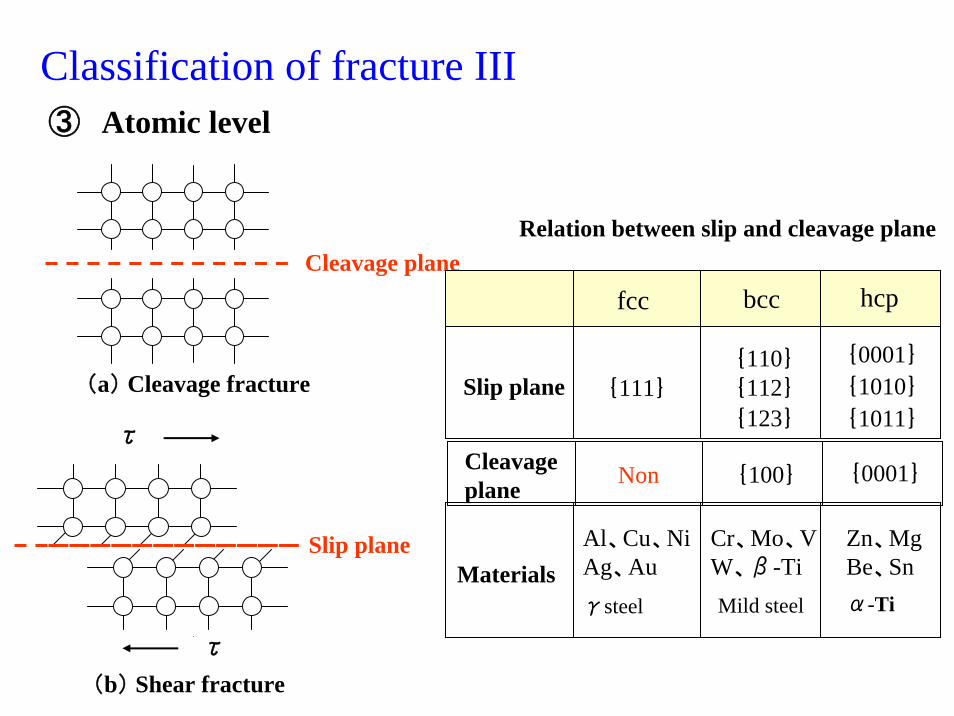
Classification of fracture III
Cleavage plane
(a) Cleavage fracture
③ Atomic level
(b) Shear fracture
τ
τ
Slip plane
Slip plane {111}
{0001}
{123}
{112}{110}
{1011}
{1010}
Cleavageplane
{0001}{100}Non
MaterialsAl、Cu、NiAg、Auγsteel
Cr、Mo、VW、β-TiMild steel
Zn、MgBe、Snα-Ti
fcc bcc hcp
Relation between slip and cleavage plane
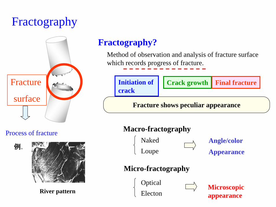
Fractography
Initiation of crack
Crack growth Final fractureFracture
surface
Fractography?Method of observation and analysis of fracture surface which records progress of fracture.
例.
River pattern
Process of fracture
Fracture shows peculiar appearance
Macro-fractographyNaked Loupe
Angle/colorAppearance
Micro-fractography
OpticalElecton
Microscopic appearance
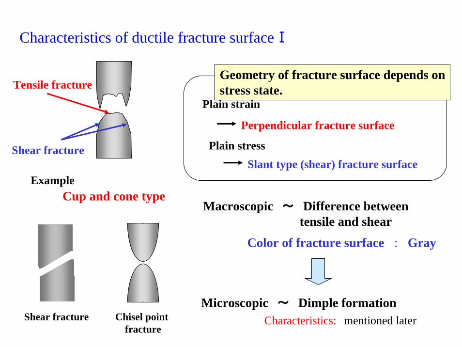
Characteristics of ductile fracture surfaceⅠ
Tensile fracture
Plain strain
Perpendicular fracture surface
Cup and cone typeExample
Geometry of fracture surface depends onstress state.
Shear fracture Plain stressSlant type (shear) fracture surface
Color of fracture surface : Gray
Macroscopic ~ Difference between tensile and shear
Microscopic ~ Dimple formationCharacteristics: mentioned laterShear fracture Chisel point
fracture
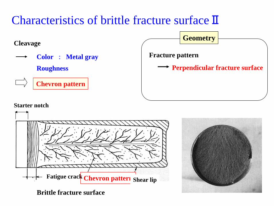
Characteristics of brittle fracture surfaceⅡ
CleavageGeometry
Fracture pattern
Perpendicular fracture surfaceColor : Metal gray
Roughness
Chevron pattern
Starter notch
Brittle fracture surface
Chevron patternFatigue crack Shear lip
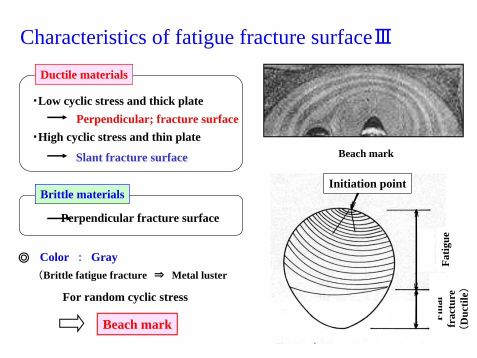
Characteristics of fatigue fracture surfaceⅢ
・Low cyclic stress and thick plate
Slant fracture surface
Perpendicular; fracture surface・High cyclic stress and thin plate
Ductile materials
Brittle materials
Perpendicular fracture surface
Color : Gray(Brittle fatigue fracture ⇒ Metal luster
◎
For random cyclic stress
Beach mark
Fatig
ueFi
nal
frac
ture
(D
uctil
e)
Initiation point
Beach mark
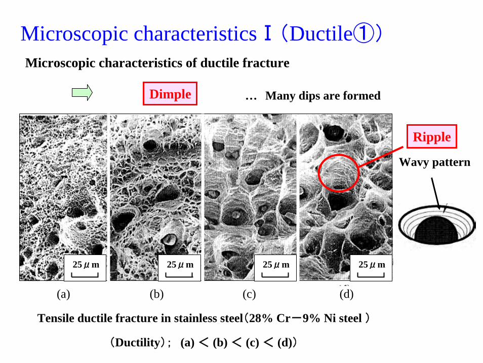
Microscopic characteristicsⅠ(Ductile①)
25μm 25μm 25μm 25μm
(a) (b) (c) (d)
Tensile ductile fracture in stainless steel(28% Cr-9% Ni steel )
(Ductility); (a) < (b) < (c) < (d))
Microscopic characteristics of ductile fracture
Dimple … Many dips are formed
Ripple
Wavy pattern
σ1
σ1
σ1σ2
σ1
τ
τ
σ2
M
M
σ1
σ1 τ
τ M
M
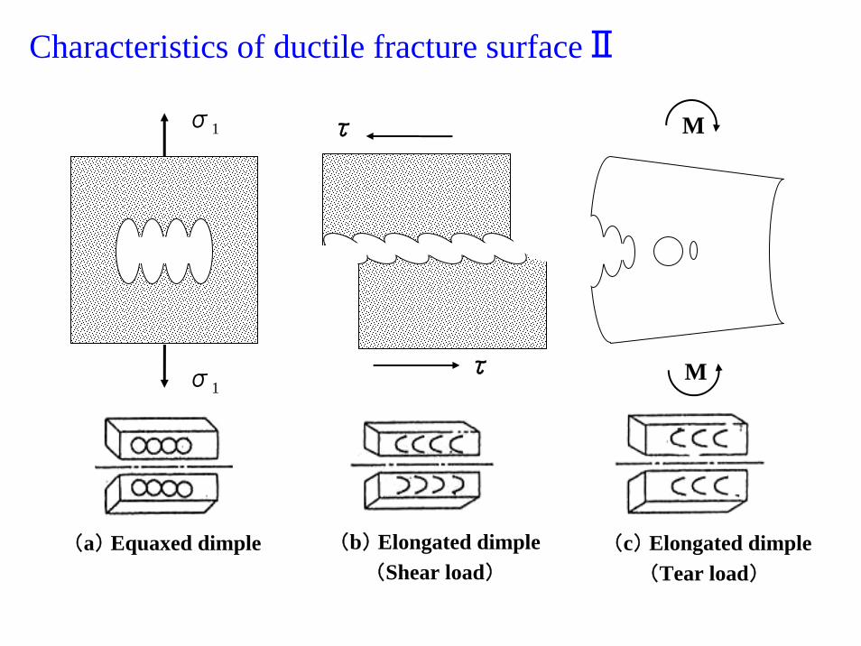
(a) Equaxed dimple (b) Elongated dimple (c) Elongated dimple(Shear load) (Tear load)
Characteristics of ductile fracture surfaceⅡ
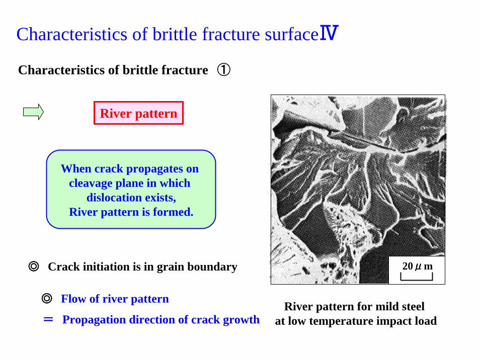
When crack propagates on cleavage plane in which
dislocation exists,River pattern is formed.
Characteristics of brittle fracture surfaceⅣ
20μm
River pattern for mild steel at low temperature impact load
Characteristics of brittle fracture ①
River pattern
◎ Flow of river pattern
= Propagation direction of crack growth
◎ Crack initiation is in grain boundary
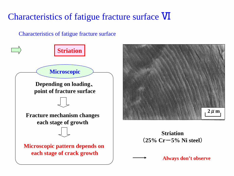
Characteristics of fatigue fracture surface Ⅵ
2μm
Striation(25% Cr-5% Ni steel)
Characteristics of fatigue fracture surface
Striation
Microscopic
Always don’t observe
Depending on loading、point of fracture surface
Fracture mechanism changes each stage of growth
Microscopic pattern depends on each stage of crack growth
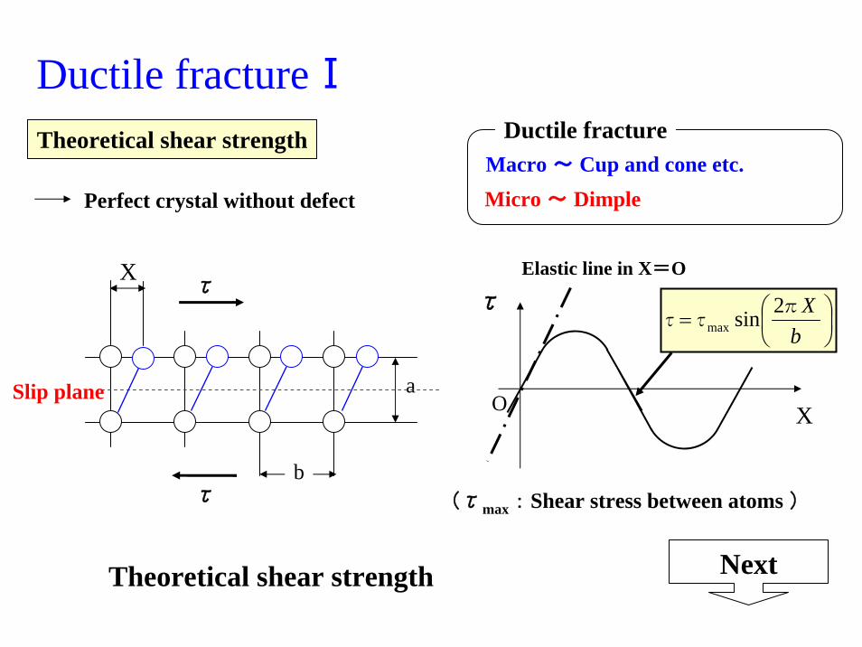
Ductile fractureⅠDuctile fracture
Macro ~ Cup and cone etc.Micro ~ Dimple
a
bτ
τ
Theoretical shear strength
Perfect crystal without defect
O X
τ
Theoretical shear strength Next
Slip plane
X Elastic line in X=O
(τmax : Shear stress between atoms )
⎟⎠⎞
⎜⎝⎛=
bXπ
ττ2sinmax
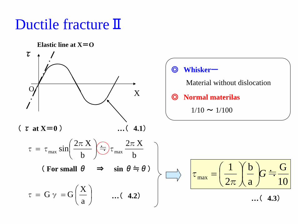
Ductile fractureⅡ
O X
τElastic line at X=O
⎟⎠⎞
⎜⎝⎛==
aXG G γ τ …( 4.2)
10G
ab
21
max ≒π
τ G⎟⎠⎞
⎜⎝⎛⎟⎠⎞
⎜⎝⎛=
…( 4.3)
( τ at X=0 )
bX2
bX2sin maxmax
πτ≒
π ττ ⎟
⎠⎞
⎜⎝⎛=
( For small θ ⇒ sin θ≒θ)
…( 4.1)
◎ Whiskerー
Material without dislocation
◎ Normal materilas
1/10 ~ 1/100
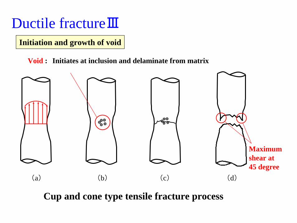
Ductile fractureⅢInitiation and growth of void
(a) (b) (c) (d)
Cup and cone type tensile fracture process
Maximum shear at 45 degree
Void : Initiates at inclusion and delaminate from matrix
Brittle fractureⅠ
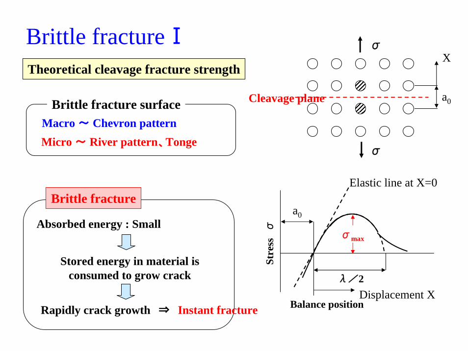
Theoretical cleavage fracture strength
Brittle fracture surfaceMacro ~ Chevron patternMicro ~ River pattern、Tonge
Brittle fracture
Absorbed energy : Small
Stored energy in material isconsumed to grow crack
Rapidly crack growth ⇒ Instant fracture
a0
λ/2
Balance positionDisplacement X
Stre
ssσ
Elastic line at X=0
σmax
Cleavage plane a0
X
σ
σ
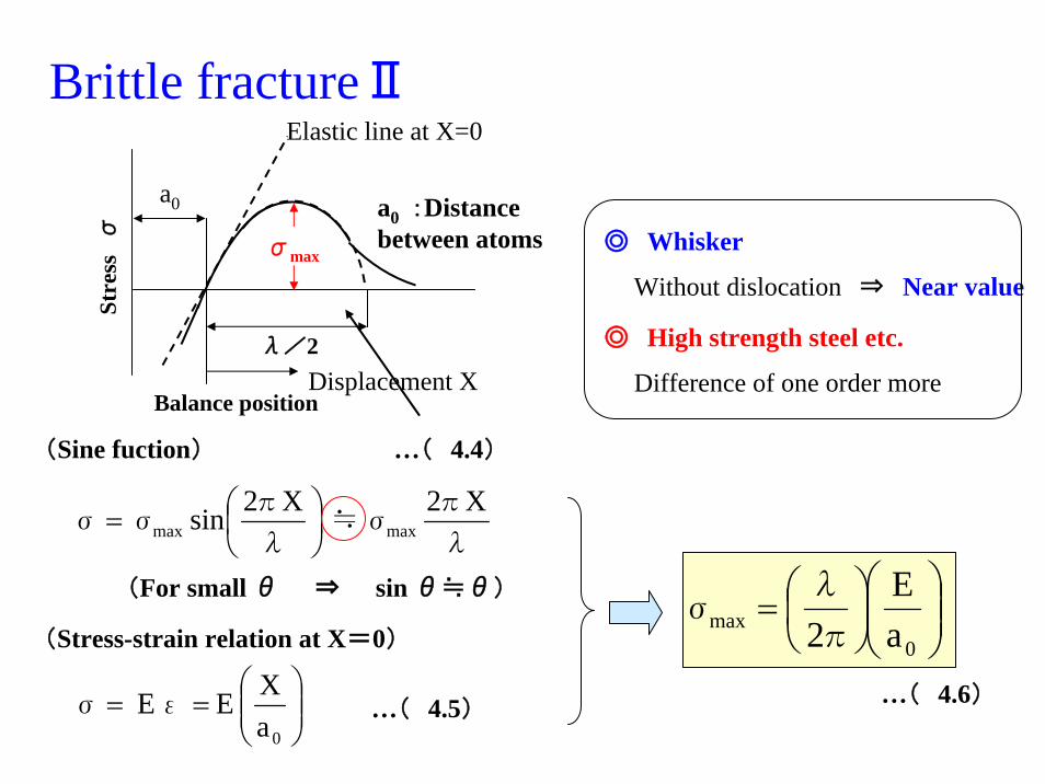
Brittle fractureⅡ
(Stress-strain relation at X=0)
⎟⎟⎠
⎞⎜⎜⎝
⎛==
0aX E E ε σ …( 4.5)
(Sine fuction)
λ
πσ≒
λ
π σσ
X2 X2sin maxmax ⎟⎠⎞
⎜⎝⎛=
(For small θ ⇒ sin θ≒θ)
…( 4.4)
a0
λ/2
Balance positionDisplacement X
Stre
ssσ
Elastic line at X=0
σmax
a0 :Distance between atoms
aE
2 0max ⎟⎟
⎠
⎞⎜⎜⎝
⎛⎟⎠⎞
⎜⎝⎛=π
λσ
…( 4.6)
◎ Whisker
Without dislocation ⇒ Near value
◎ High strength steel etc.
Difference of one order more
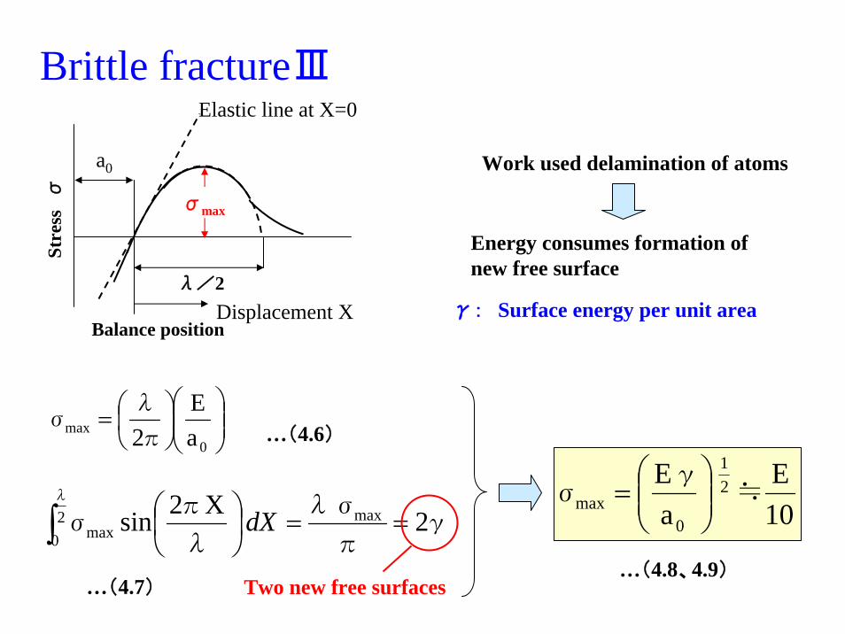
Brittle fractureⅢ
a0
λ/2
Balance positionDisplacement X
Stre
ssσ
Elastic line at X=0
σmax
aE
2 0max ⎟⎟
⎠
⎞⎜⎜⎝
⎛⎟⎠⎞
⎜⎝⎛=π
λσ
…(4.6)
Work used delamination of atoms
γπ
λσ
λ
πσ
λ
2 X2sin max20 max ==⎟
⎠⎞
⎜⎝⎛∫ dX
Two new free surfaces…(4.7)
Energy consumes formation of new free surface
γ: Surface energy per unit area
10E
aE 2
1
0max ≒
γσ ⎟⎟
⎠
⎞⎜⎜⎝
⎛=
…(4.8、4.9)
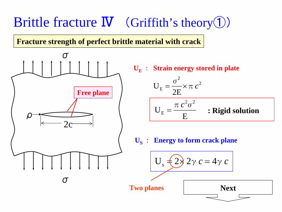
Brittle fracture Ⅳ (Griffith’s theory①)
UE : Strain energy stored in plate
22
E 2EU cπ
σ×=
EU
22
Eσπc
= : Rigid solution
US : Energy to form crack plane
cc γγ 422Us =×=
Nextσ
σ
2cρ
Free plane
Two planes
Fracture strength of perfect brittle material with crack
dcdU
dcdU SE =
Criterion of fracture
…(4.12)
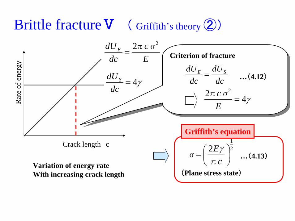
Brittle fractureⅤ ( Griffith’s theory ②)
Ec
dcdUE
22 σπ=
γ4=dc
dUS
Crack length c
Rat
e of
ene
rgy
Variation of energy rate With increasing crack length
γ42 2
=Ecσπ
21
2⎟⎠⎞
⎜⎝⎛=
cE
πσ
γ
Griffith’s equation
…(4.13)
(Plane stress state)
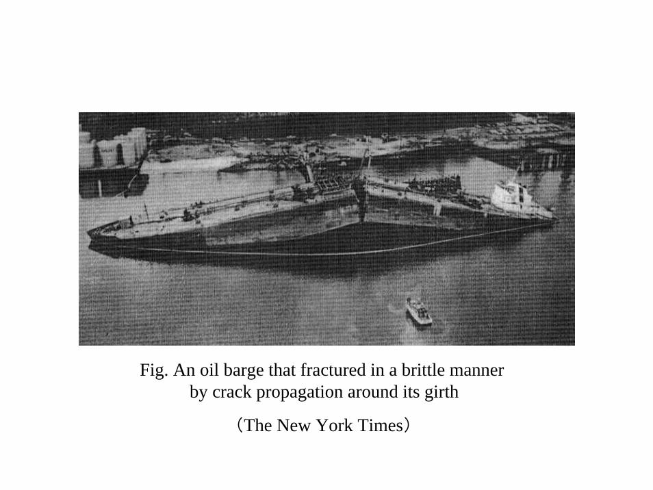
Fig. An oil barge that fractured in a brittle manner by crack propagation around its girth
(The New York Times)
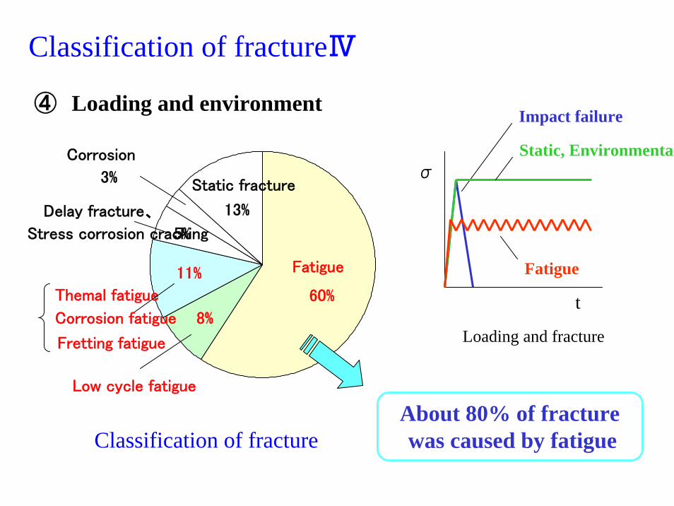
Classification of fractureⅣ
④ Loading and environment
Classification of fracture
Static fracture
13%
Corrosion
3%
Delay fracture、
Stress corrosion cracking5%
Themal fatigue
Corrosion fatigue
Fretting fatigue
11% Fatigue
60%
Low cycle fatigue
8%
About 80% of fracture was caused by fatigue
Impact failure
σ
t
Loading and fracture
Static, Environmental
Fatigue
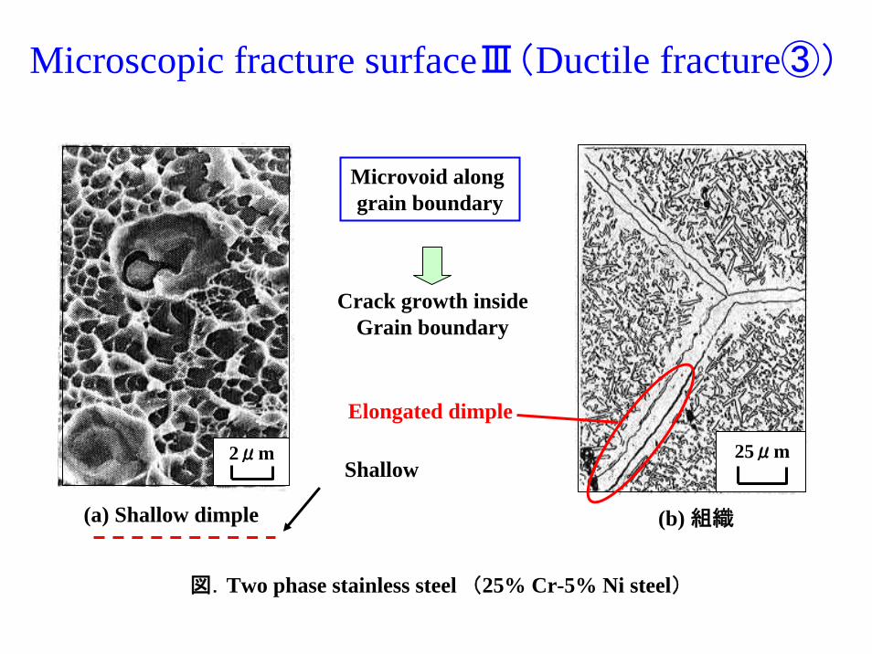
Microscopic fracture surfaceⅢ(Ductile fracture③)
2μm
(a) Shallow dimple
25μm
(b) 組織
図.Two phase stainless steel (25% Cr-5% Ni steel)
Shallow
Microvoid along grain boundary
Crack growth insideGrain boundary
Elongated dimple
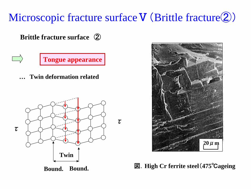
Microscopic fracture surfaceⅤ(Brittle fracture②)
20μm
図.High Cr ferrite steel(475℃ageing
Brittle fracture surface ②
Tongue appearance
… Twin deformation related
ττ
Bound. Bound.
Twin
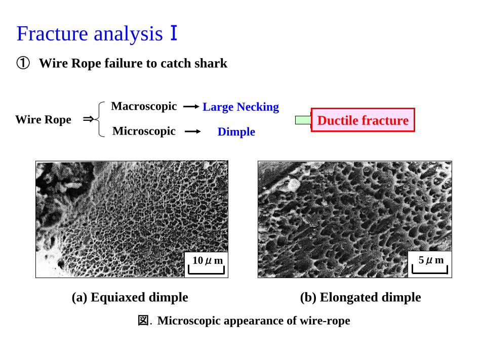
Fracture analysisⅠ① Wire Rope failure to catch shark
Wire Rope ⇒Macroscopic Large Necking
Ductile fractureMicroscopic Dimple
5μm10μm
(a) Equiaxed dimple (b) Elongated dimple
図.Microscopic appearance of wire-rope
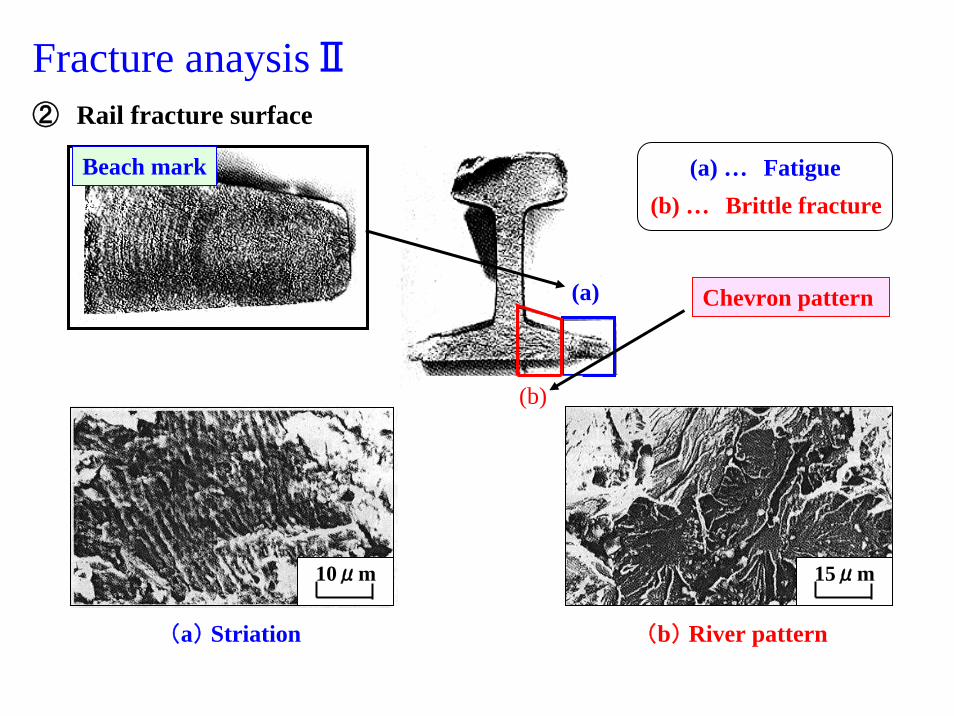
Fracture anaysisⅡ② Rail fracture surface
10μm
(a) Striation
Beach mark
(a)
(b)
Chevron pattern
(b) River pattern
15μm
(a) … Fatigue(b) … Brittle fracture
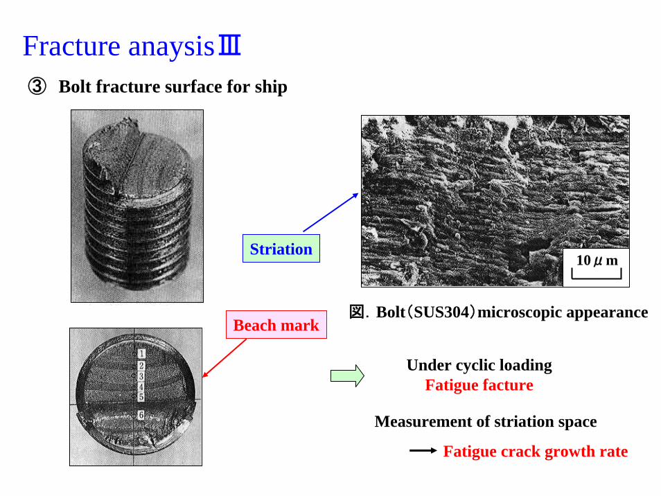
Fracture anaysisⅢ③ Bolt fracture surface for ship
Measurement of striation space
Fatigue crack growth rate
Beach mark
10μm
図.Bolt(SUS304)microscopic appearance
Striation
Under cyclic loadingFatigue facture
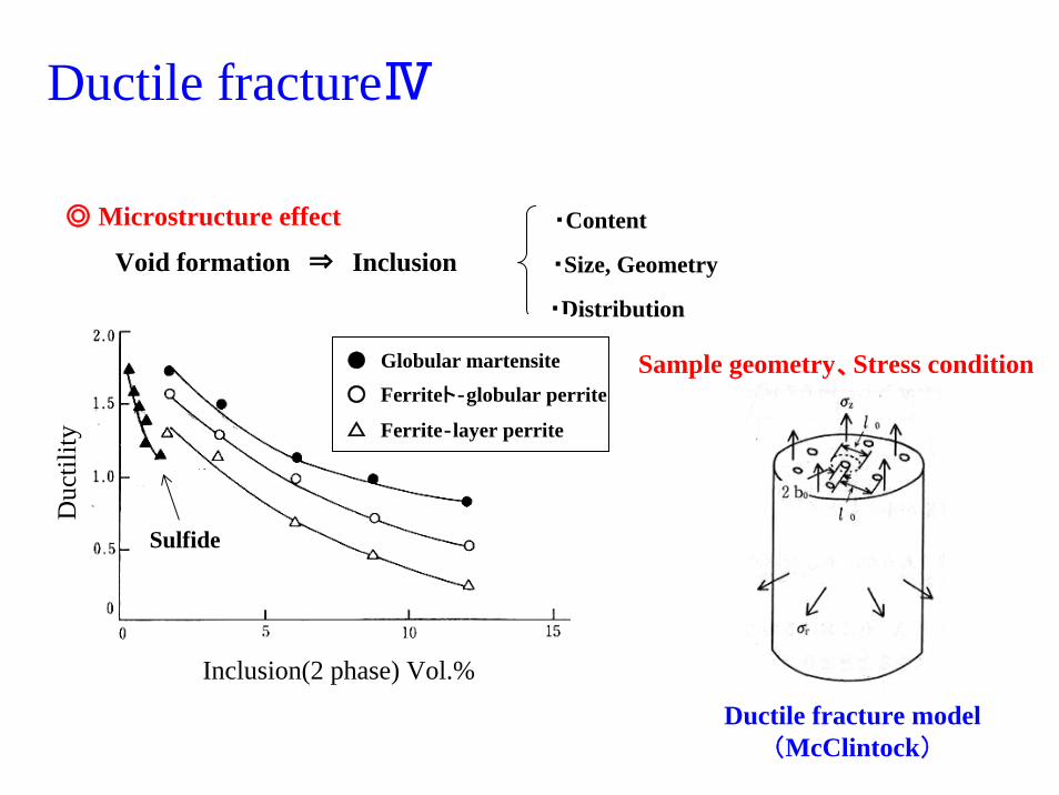
Ductile fractureⅣ
◎ Microstructure effect
Void formation ⇒ Inclusion・Content
・Distribution
・Size, Geometry
● Globular martensite
○ Ferriteト‐globular perrite
Sulfide
△ Ferrite‐layer perrite
Inclusion(2 phase) Vol.%
Duc
tility
Sample geometry、Stress condition
Ductile fracture model(McClintock)
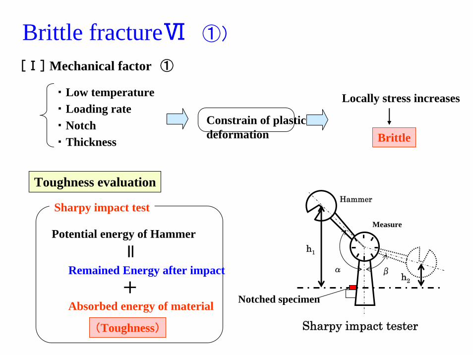
Brittle fractureⅥ ①)
[Ⅰ] Mechanical factor ①
・ Low temperature・ Loading rate・ Notch・ Thickness
Constrain of plasticdeformation
Locally stress increases
Brittle
Sharpy impact tester
Hammer
α β
h1
h2
Measure
Notched specimen
Potential energy of Hammer
Toughness evaluation
Sharpy impact test
Remained Energy after impact
Absorbed energy of material+
=(Toughness)
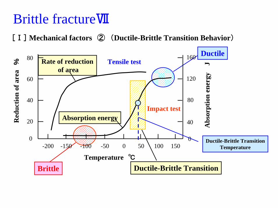
Brittle fractureⅦ[Ⅰ] Mechanical factors ② (Ductile-Brittle Transition Behavior)
Rate of reductionof area
Tensile test
Brittle
Ductile
-200 -150 -50-100 0 50 100 1500
20
60
40
80
0
80
160
40
120
Temperature ℃
Red
uctio
n of
are
a%
Abs
orpt
ion
ener
gyJ
Ductile-Brittle Transition
Absorption energyImpact test
Ductile-Brittle TransitionTemperature
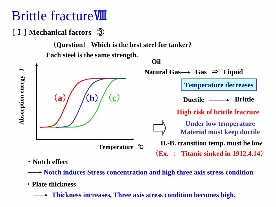
Brittle fractureⅧ[Ⅰ] Mechanical factors ③
(Question) Which is the best steel for tanker?Each steel is the same strength.
(a) (b) (c)
Temperature ℃
Abs
orpt
ion
ener
gyJ
D.-B. transition temp. must be low
Temperature decreases
High risk of brittle fracrure
Ductile Brittle
OilNatural Gas Gas ⇒ Liquid
Under low temperatureMaterial must keep ductile
・ Notch effectNotch induces Stress concentration and high three axis stress condition
・ Plate thicknessThickness increases, Three axis stress condition becomes high.
(Ex. : Titanic sinked in 1912.4.14)
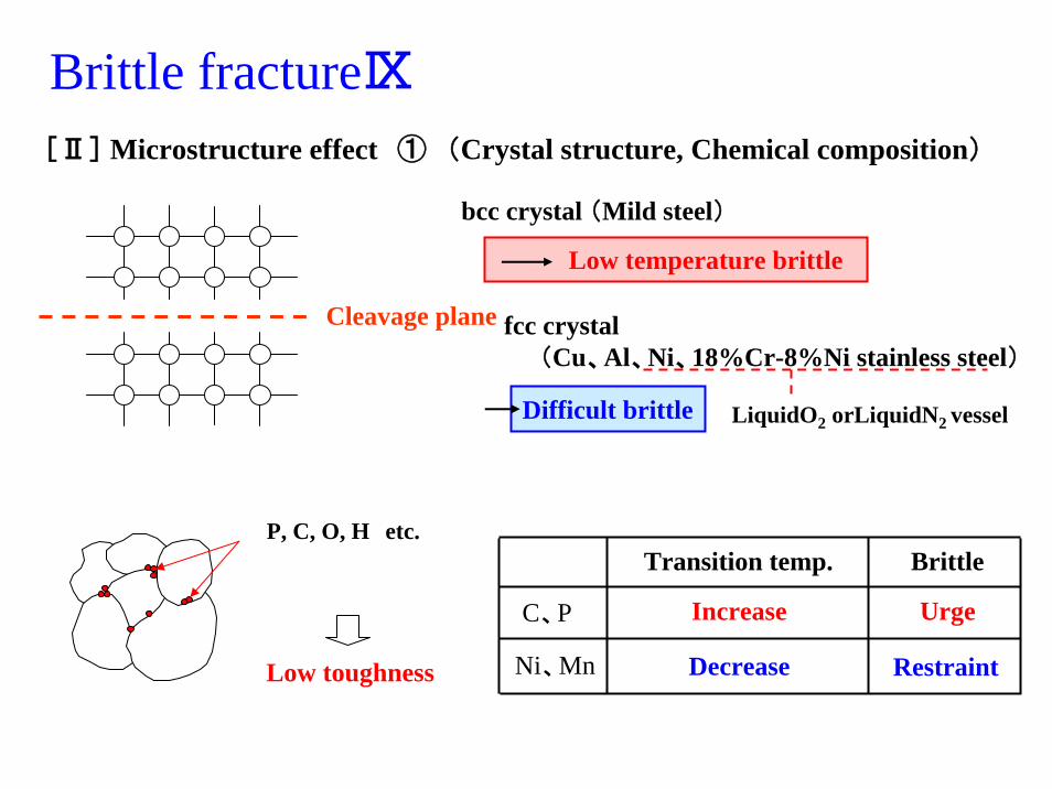
Brittle fractureⅨ
P, C, O, H etc.
Low toughness
σ
σ
Cleavage plane
[Ⅱ] Microstructure effect ① (Crystal structure, Chemical composition)
bcc crystal (Mild steel)
fcc crystal(Cu、Al、Ni、18%Cr-8%Ni stainless steel)
Difficult brittle
Low temperature brittle
LiquidO2 orLiquidN2 vessel
C、P
Transition temp.
Ni、Mn
Brittle
Increase Urge
Decrease Restraint
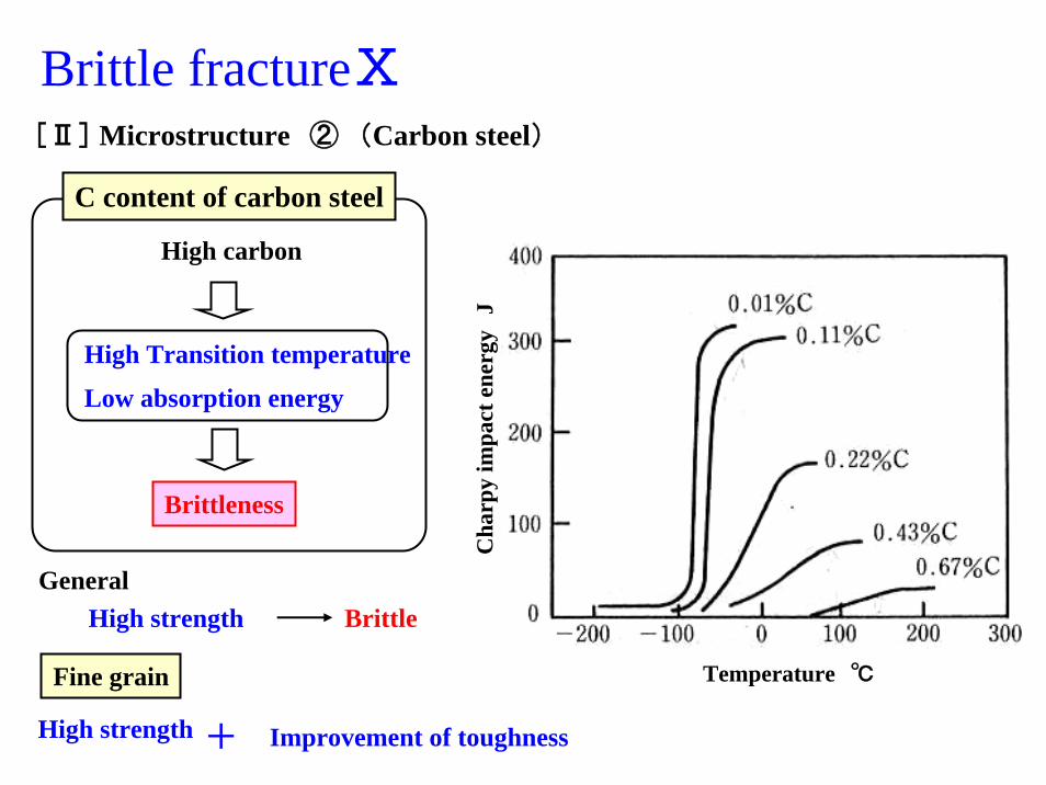
Brittle fractureⅩ[Ⅱ] Microstructure ② (Carbon steel)
Temperature ℃
Cha
rpy
impa
ct e
nerg
yJ
High carbon
High Transition temperature
Low absorption energy
Brittleness
C content of carbon steel
GeneralHigh strength Brittle
Fine grain
High strength Improvement of toughness+
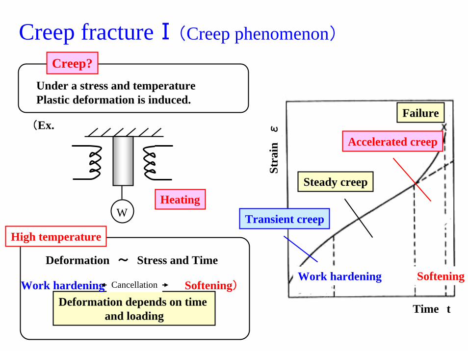
Creep fractureⅠ(Creep phenomenon)
(Ex.
WHeating
Under a stress and temperaturePlastic deformation is induced.
Creep?
Failure
Time t
Stra
inε
Accelerated creep
Softening
Transient creep
Work hardening
Steady creep
Deformation depends on time and loading
Work hardening Softening)Cancellation
Deformation ~ Stress and Time
High temperature

Creep fractureⅡ(Creep strength)
Failure
Time t
Stra
inε
Steady creep
Creep rate
Creep rate at steady creep stage
Small creep rate
Time to tolerance strain=long using period
Creep strength
A constant stress of 100MPa103 Hours
Strain=0.01% (例)
Creep strength =100MPa at 0.01% / 103 h
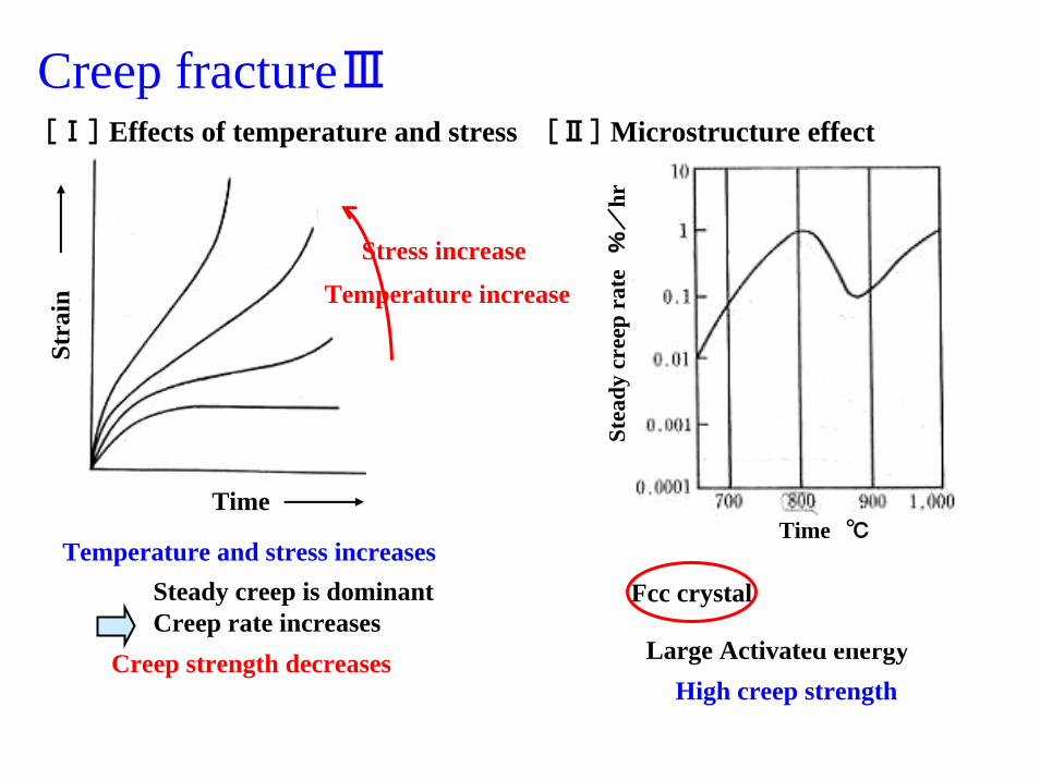
Creep fractureⅢ[Ⅰ] Effects of temperature and stress [Ⅱ] Microstructure effect
Time
Stra
in
Stress increase
Temperature increase
Temperature and stress increasesSteady creep is dominant Creep rate increases
Creep strength decreases
Time ℃
Stea
dy c
reep
rat
e%
/hr
Fcc crystal
High creep strengthLarge Activated energy
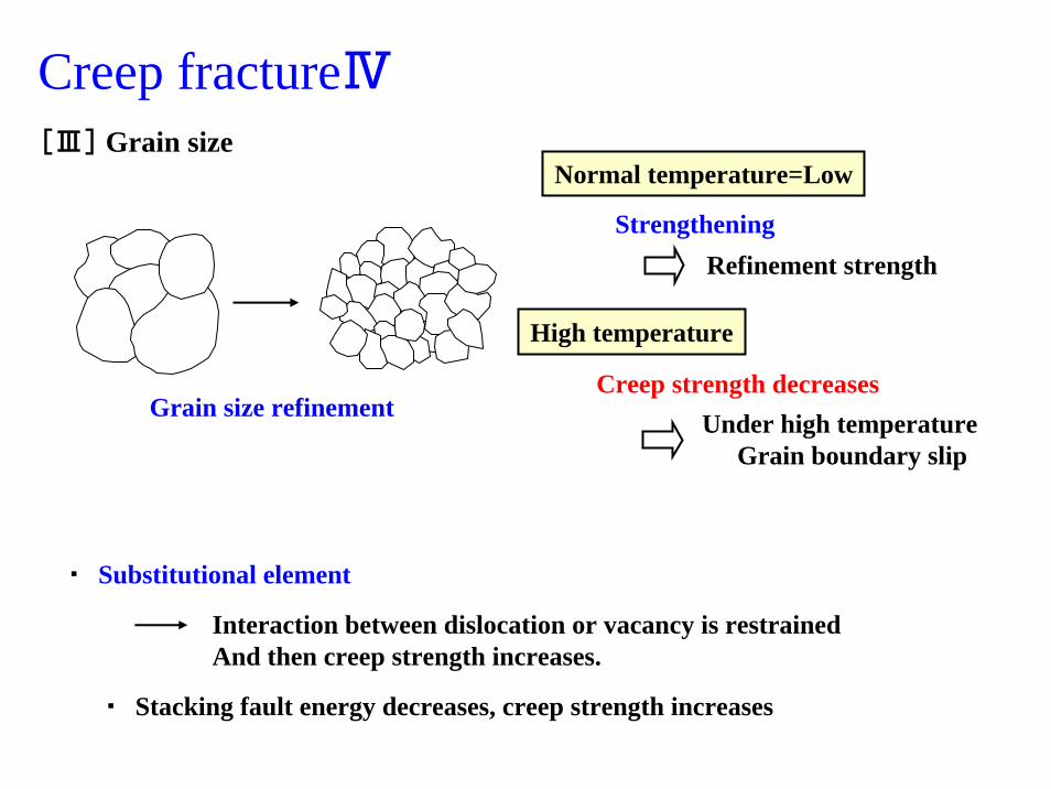
Creep fractureⅣ[Ⅲ] Grain size
Grain size refinement
Normal temperature=Low
StrengtheningRefinement strength
Creep strength decreasesUnder high temperature
Grain boundary slip
High temperature
・ Substitutional element
Interaction between dislocation or vacancy is restrainedAnd then creep strength increases.
・ Stacking fault energy decreases, creep strength increases
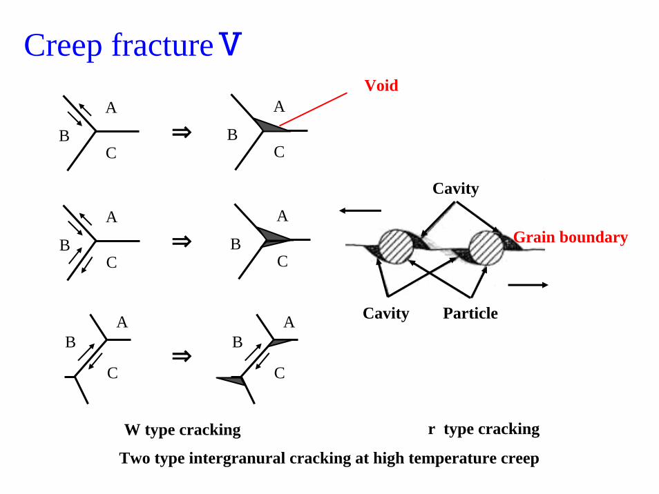
Creep fractureⅤ
A
BC
A
BC
C
BA
A
BC
⇒
A
BC
⇒
C
BA
⇒
Void
ParticleCavity
Cavity
Grain boundary
W type cracking r type cracking
Two type intergranural cracking at high temperature creep

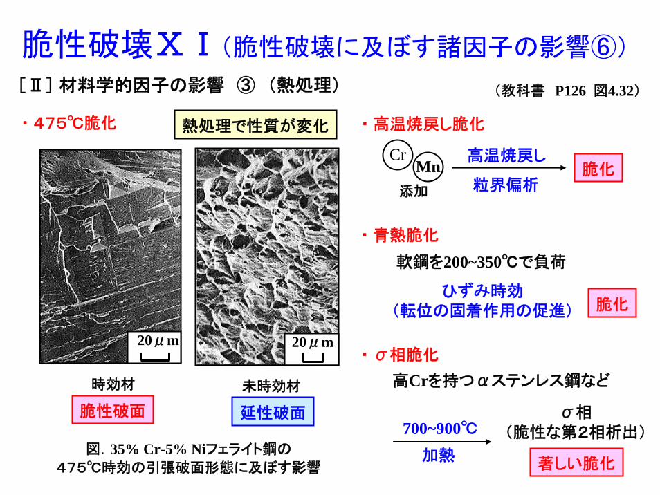
脆性破壊ⅩⅠ(脆性破壊に及ぼす諸因子の影響⑥)
[Ⅱ] 材料学的因子の影響 ③ (熱処理)
・ 高温焼戻し脆化
CrMn
添加
高温焼戻し
粒界偏析脆化
・ 青熱脆化
軟鋼を200~350℃で負荷
ひずみ時効(転位の固着作用の促進) 脆化
・ σ相脆化
高Crを持つαステンレス鋼など
700~900℃
加熱
σ相(脆性な第2相析出)
著しい脆化
脆性破面 延性破面
熱処理で性質が変化・ 475℃脆化
20μm
時効材
20μm
未時効材
図.35% Cr-5% Niフェライト鋼の
475℃時効の引張破面形態に及ぼす影響
(教科書 P126 図4.32)

巨視的破面の特徴Ⅳ(疲労破面②)
1mm
図.粗大結晶粒をもつ二相ステンレス鋼(25% Cr-5% Ni鋼)
(教科書 P100, 図4.6)
疲労破壊
微視組織の影響 大
結晶粒ごとにき裂の進展方向が変化
組織の痕跡が破面上に残る
※ 脆性破面も巨視的には類似
微視的な特徴(破壊機構)が異なる
破面の色彩
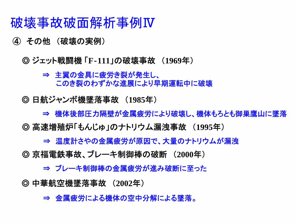
破壊事故破面解析事例Ⅳ
④ その他 (破壊の実例)
◎ ジェット戦闘機 「F‐111」の破壊事故 (1969年)
◎ 日航ジャンボ機墜落事故 (1985年)
◎ 高速増殖炉「もんじゅ」のナトリウム漏洩事故 (1995年)
◎ 京福電鉄事故、ブレーキ制御棒の破断 (2000年)
◎ 中華航空機墜落事故 (2002年)
⇒ 金属疲労による機体の空中分解による墜落。
⇒ 主翼の金具に疲労き裂が発生し、このき裂のわずかな進展により早期運転中に破壊
⇒ 機体後部圧力隔壁が金属疲労により破壊し、機体もろとも御巣鷹山に墜落
⇒ 温度計さやの金属疲労が原因で、大量のナトリウムが漏洩
⇒ ブレーキ制御棒の金属疲労が進み破断に至った