University of ConnecticutOpenCommons@UConn
SoDM Masters Theses School of Dental Medicine
6-1-1992
Force Systems from T-Loop Orthodontic SpaceClosure Springs: The Effects of AsymmetricPlacement and Angulation on the Alpha-BetaMoment DifferentialAndrew J. Kuhlberg
Follow this and additional works at: https://opencommons.uconn.edu/sodm_masters
Part of the Orthodontics and Orthodontology Commons
Recommended CitationKuhlberg, Andrew J., "Force Systems from T-Loop Orthodontic Space Closure Springs: The Effects of Asymmetric Placement andAngulation on the Alpha-Beta Moment Differential" (1992). SoDM Masters Theses. 73.https://opencommons.uconn.edu/sodm_masters/73
FORCE SYSTEMS FROM "T-LOOP ORTHODONTIC SPACE CLOSURE SPRINGS:
THE EFFECTS OF ASYMMETRIC PLACEMENT AND
ANGULATION ON THE ALPHA-BETA MOMENT DIFFERENTIAL
Andrew J. Kuhlberg
B.A., Hartwick College, 1984
D.M.D., University of Connecticut, 1989
A Thesis
Submitted in Partial Fulf’dlment of the
Requirements for the Degrees of
Master of Dental Science
The University of Connecticut
1992
APPROVAL PAGE
Master of Dental Science
FORCE SYSTEMS FROM "T-LOOP ORTHODONTIC SPACE CLOSURE SPRINGS"
THE EFFECTS OF ASYMMETRIC PLACEMENTAND
ANGULATION ON THE ALP-BETA MOMENT DIFFERENTIAL
Presented by
Andrew J. Kuhlberg, B.A., D. M. D.
Major AdviserCharles J. Burstone
Associate Adviser.." Louis NortonAssociate Adviser
Dubravko Pavlin
The University of Connecticut
1992

ACKNOWLEDGEMENTS
I would like to thank the members of my advisory committe, Dr. Louis A. Norton
and Dr. Dubravko Pavlin for their guidance with this project. I would especially like to
thank Dr. Charles Burstone for his invaluable contributions to my training and education,
his knowledge and wisdom have guided me throughout my cm’er at the University of
Connecticut.
I would also like to thank John Morton and John Ratches, as well as all the past
research technicians and students who have worked in the Biomechanics Laboratory, for
their contributions to the creation and evolution of the equipment needed to accomplish this
research.
A very grateful thank you to my parents for their support and encouragement as
I’ve pursued my education.
And most of all, thank you to my wife, Laura, for her love, support, and
inspiration..
iii
TABLE,OF CONTENTS
IN’IODUCTION
LITERATURE REVIEW 4
RATIONALE 17
GENERAL OBJECTIVES 18
THE RESEARCH PLAN 19
RESULTS 25
DISCUSSION 31
CONCLUSIONS 35
FUTURE STUDIES 36
REFERENCES 37
APPENDIX I: TABLES 39
APPENDIX II: FIGURES 86
iv

LIST OF TABLES
Table# Title
SUMMARY OF MEASURED FORCE SYSTEMSymmetric Angulation, Centered Position,Preactivation Angulation = 0 degrees
39
2: SUMMARY OF MEASURED FORCE SYSTEMSymmetric Angulation, Centered Position,Preactivation Angulation = 10 degrees
40
3." SUMMARY OF MEASURED FORCE SYSTEMSymmetric Angulation, Centered Position,Preactivation Angulation = 20 degrees
41
4." SUMMARY OF MEASURED FORCE SYSTEMSymmetric Angulation, Centered Position,Preactivation Angulation = 30 degrees
42
5." SUMMARY OF MEASURED FORCE SYSTEMSymmetric Angulation, Centered Position,Preactivation Angulation = 40 degrees
43
6". SUMMARY OF MEASURED FORCE SYSTEMSymmetric Anguladon, Centered Position,Preactivation Angulation = 50 degrees
7." SUMMARY OF MEASURED FORCE SYSTEMSymmetric Angulation, Centered Position,Preactivation Angulation = 60 degrees
45
8; SUMMARY OF MEASURED FORCE SYSTEMSymmetric Angulation, Centered Position,Preactivation Angulation = 70 degree
46
9: SUMMARY OF MEASURED FORCE SYSTEMSymmetric Moments, Centered Position (Control),
10: SUMMARY OF MEASURED FORCE SYSTEMSymmetric Moments, Positioned 1 mm toward Anterior (Alpha)
48
SUMMARY OF MEASURED FORCE SYSTEMSymmetric Moments, Positioned 2 mm toward Anterior (Alpha)
49
SUMMARY OF MEASURED FORCE SYSTEMSymmetric Moments, Positioned 3 mm toward Anterior (Alpha)
50
SUMMARY OF MEASURED FORCE SYSTEMSymmetric Moments, Positioned 4 mm toward Anterior (Alpha)
51
14:
16:
SUMMARY OF MEASURED FORCE SYSTEMSymmetric Moments, Positioned 1 mm toward Posterior (Beta)
SUMMARY OF MEASURED FORCE SYSTEMSymmetric Moments, Positioned 2 mm toward Posterior (Beta)
SUMMARY OF MEASURED FORCE SYSTEMSymmetric Moments, Positioned 3 mm toward Posterior (Beta)
SUMMARY OF MEASURED FORCE SYSTEMSymmetric Moments, Positioned 4 mm toward Posterior (Beta)
SUMMARY OF MEASURED FORCE SYSTEMAsymmetric Angulation: Alpha = 0 degrees, Beta = 75 degrees,Centered Position
52
53
54
55
56
19:
20:
22:
SUMMARY OF MEASURED FORCE SYSTEMAsymmetric Angulation: Alpha = 15 degrees, Beta = 75 degrees,Centered Position
SUMMARY OF MEASURED FORCE SYSTEMAsymmetric Angulation: Alpha = 30 degrees, Beta = 75 degrees,Centered Position
SUMMARY OF MEASURED FORCE SYSTEMAsymmetric Angulation: Alpha = 45 degrees, Beta = 75 degrees,Centered Position
SUMMARY OF MEASURED FORCE SYSTEMAsymmetric Angulation: Alpha = 60 degrees, Beta = 75 degrees,Centered Position
57
58
59
60
23: SUMMARY OF MEASURED FORCE SYSTEMAsymmetric Angulation: Alpha = 75 degrees, Beta = 0 degrees,Centered Position
61
24:
25:
SUMMARY OF MEASURED FORCE SYSTEMAsymmetric Angulation: Alpha = 75 degrees, Beta = 15 degrees,Centered Position
SUMMARY OF MEASURED FORCE SYSTEMAsymmetric Angulation: Alpha = 75 degrees, Beta = 30 degrees,Centered Position
62
63
SUMMARY OF MEASURED FORCE SYSTEMAsymmetric Angulation: Alpha = 75 degrees, Beta = 45 degrees,Centered Position
64
vi
SUMMARY OFMEASURED FORCE SYSTEMAsymmetric Angulation: Alpha = 75 degrees, Beta = 60 degrees,Centered Position
65
REGRESSION ANALYSIS: WHOLE MODEL- Alpha MomentSymmetric Angulation, Centered Position
66
29: RERESSION ANALYSIS: WHOLE MODEL- Beta MomentSymmetric Angulation, Centered Position
67
30: REGRESSION ANALYSIS: WHOLE MODEL- Horizontal ForceSymmetric Angulation, Centered Position
68
REGRESSION ANALYSIS: WHOLE MODEL Vertical ForceSymmetric Angulation, Centered Position
69
32: REGRESSION ANALYSIS: WHOLE MODEL-Alpha Moment/Beta Moment, Symmetric Angulation, Centered Position
70
33: REGRESSION ANALYSIS: WHOLE MODEL Alpha MomentSymmetric Moments, Off-Centered Position
71
34: REGRESSION ANALYSIS: WHOLE MODEL- Beta MomentSymmetric Moments, Off-Centered Position
72
35: REGRESSION ANALYSIS: WHOLE MODEL- Horizontal ForceSymmetric Moments, Off-Centered Position
73
36: REGRESSION ANALYSIS: WHOLE MODEL Vertical ForceSymmetric Moments, Off-Centered Position
74
37: REGRESSION ANALYSIS: WHOLE MODEL-Alpha Moment/Beta Moment, Symmetric Moments, Off-Centered Position
75
38: RFZ;RESSION ANALYSIS: WHOLE MODEL- Alpha MomentAsymmetric Angulation Varying Alpha, Centered Position
76
39: REGRESSION ANALYSIS: WHOLE MODEL- Beta MomentAsymmetric Angulation Varying Alpha, Centered Position
77
REGRESSION ANALYSIS: WHOLE MODEL- Horizontal ForceAsymmetric Angulation Varying Alpha, Centered Position
78
RFA3RESSION ANALYSIS: WHOLE MODEL Vertical ForceAsymmetric Angulation Varying Alpha, Centered Position
79
42: REGRESSION ANALYSIS: WHOLE MODEL-Alpha Moment/Beta MomentAsymmetric Angulation Varying Alpha, Centered Position
8O
vii
45:
46:
RF3RESSION ANALYSIS: WHOLEMODEL Alpha Moment.Asymmetric Angulation- VaryingBeta, Centered-Position
RERESSION ANALYSIS: WHOLEMODEL -Beta MomentAsymmetric Angulation Varying Beta, CenteredPosition
REGRESSION ANALYSIS: WHOLE MODEL- Horizontal ForceAsymmetric Angulation Varying Beta, Centered Position
REGRESSION ANALYSIS: WHOLEMODEL- Vertical ForceAsymmetric Angulation Varying Beta, Centered Position
REGRESSION ANALYSIS: WHOLE MODEL-Alpha Moment/Beta MomentAsymmetric Angulation Varying Beta, Centered Position
81
82
83
84
85
viii
LIST OF FIGURES
Figure # Title Pae
Schematic Diagram of Spring Tester Apparatus,University of Connecticut, Division of Orthodontics,Biomechanics Laboratory
86
2: The Force System from a T-loop Space Closing Spring 87
3." Segmented T-loop prior to the placement of Preactivation Bends 88
4." Templates for T-loop Springs with Symmetric Angulationand Centered Position
89
5." Templates for T-loop Springs producing Symmetric Momentsin the Centered Position, Used for Off-Centered Positioning
90
6". Templates for T-loop Springs with Asymmetric Angulation,Constant Alpha Angulation, Varying Beta Angulation
91
Templates for T-loop Springs with Asymmetric Angulation,Constant Beta Angulation, Varying Alpha Angulation
92
8; Alpha moment versus spring activation for T-loop springs with symmetricalpha and beta angulation and centered positioning
93
9" Alpha moment versus spring angulation for T-loop springs with symmetric 94alpha and beta angulation and centered positioning
10: Beta moment versus spring activation for T-loop springs with symmetricalpha and beta angulation and centered positioning
95
Beta moment versus spring angulation for T-loop springs with symmetricalpha and beta angulation and centered positioning
96
12: Horizontal Force versus spring activation for T-loop springswith symmetricalpha and beta angulation and centered positioning
97
Horizontal Force versus spring angulation for T-loop springswith symmetricalpha and beta angulation and centered positioning
98
14: Vertical Force versus spring activation for T-loop springs with symmetricalpha and beta angulation and centered positioning
99
Vertical Force versus spring angulation for T-loop springs with symmetricalpha and beta angulation and centered positioning
100
16: Ratio of the alpha moment/beta moment versus spring activation for T-loop 101springs with symmetric alpha and beta angulation and centered positioning
ix
17:
20:
22:
23:
24:
25:
26:
27:
28:
29:
Ratio of the alpha moment/beta moment versus spring angulation forT-loop springs with symmetric alpha and beta angulation andcentered positioning
Alpha moment-m-force ratio versus spring activation forT-loop springs with symmetric alpha and beta angulationand centered positioning
Beta moment-to-force ratio versus spring activation for T-loop springswith symmetric alpha and beta angulation and centered positioning
Alpha moment versus spring activation for symmetric T-loop springsat various off-centered positions
Alpha moment versus spring position for symmetric T-loop springsat various off-centered positions
Beta moment versus spring activation for symmetric T-loop springsat various off-centered position
Beta moment versus spring position for symmetric T-loop springsat various off-centered positions
Horizontal Force versus spring activation for symmetric T-loop springsat various off-centered positions
Horizontal Force versus spring position for symmetric T-loop springsat various off-centered positions
Vertical Force versus spring activation for symmetric T-loop springsat various off-centered positions
Vertical Force versus spring position for symmetric T-loop springsat various off-centered positions
Ratio of the alpha moment/beta moment versus spring activationfor symmetric T-loop springs at various off-centered positions
Ratio of the alpha moment/beta moment versus spring positionfor symmetric T-loop springs at various off-centered positions
102
103
104
105
106
107
108
109
110
111
112
113
114
30:
34:
35:
39:
Alpha moment-to-force ratio versus spring activation for symmetric T-loop 115springs with at various off-centered positions
Beta moment-to-force ratio versus spring activation for symmetric T-loopsprings with at various off-centered positions
116
Alpha moment versus spring activation for T-loop springswith asymmetric alpha and beta angulation and centered position,variation of alpha angulation (0, 15, 30, 45, and 60 degrees)with constant beta angulation (75 degrees)
117
Alpha moment versus alpha angulation for T-loop springswith asymmetric alpha and beta angulation and centered position,variation of alpha angulation (0, 15, 30, 45, and 60 degrees)with constant beta angulation (75 degrees)
118
Beta moment versus spring activation for T-loop springswith asymmetric alpha and beta angulation and centered position,variation of alpha angulation (0, 15, 30, 45, and 60 degrees)with constant beta angulation (75 degrees)
119
Beta moment versus alpha angulation for T-loop springswith asymmetric alpha and beta angulation and centered position,variation of alpha angulation (0, 15, 30, 45, and 60 degrees)with constant beta angulation (75 degrees)
120
Horizontal Force versus spring activation for T-loop springswith asymmetric alpha and beta angulation and centered position,variation of alpha angulation (0, 15, 30, 45, and 60 degrees)with constant beta angulation (75 degrees)
121
Horizontal Force versus alpha angulation for T-loop springswith asymmetric alpha and beta angulation and centered position,variation of alpha angulation (0, 15, 30, 45, and 60 degrees)with constant beta angulation (75 degrees)
122
Vertical Force versus spring activation for T-loop springswith asymmetric alpha and beta angulation and centered position,variation of alpha angulation (0, 15, 30, 45, and 60 degrees)with constant beta angulation (75 degrees)
123
Vertical Force versus alpha angulation for T-loop springswith asymmetric alpha and beta angulation and centered position,variation of alpha angulation (0, 15, 30, 45, and 60 degrees)with constant beta angulation (75 degrees)
124
Ratio of the alpha momentta moment versus spring activationfor T-loop springs with asymmetric alpha and beta angulationand centered position, variation of alpha angulation(0, 15, 30, 45, and 60 degrees) with constant beta angulation (75 degrees)
125
xi
41" 126
42:
43:
50:
Alpha moment-to-force ratio versus spring activation for T-loopsprings with asymmetric alpha and beta angulation and centered position,variation of alpha angulation (0, 15, 30, 45, and 60 degrees)with constant beta angulation (75 degrees)
Beta moment-to-force ratio versus spring activation for T-loopsprings with asymmetric alpha and beta angulation and centered position,variation of alpha angulation (0, 15, 30, 45, and 60 degrees)with constant beta angulation (75 degrees)
Alpha moment versus spring activation for T-loop springswith asymmetric alpha and beta angulation and centered position,variation of beta angulation (0, 15, 30, 45, and 60 degrees)with constant alpha angulation (75 degrees)
Alpha moment versus beta angulation for T-loop springswith asymmetric alpha and beta angulation and centered position,variation of beta angulation (0, 15, 30, 45, and 60 degrees)with constant alpha angulation (75 degrees)
Beta moment versus spring activation for T-loop springswith asymmetric alpha and beta angulation and centered position,variation of beta angulation (0, 15, 30, 45, and 60 degrees)with constant alpha angulation (75 degrees)
Beta moment versus beta angulation for T-loop springs with asymmetricwith asymmetric alpha and beta angulation and centered position,variation of beta angulation (0, 15, 30, 45, and 60 degrees)with constant alpha angulation (75 degrees)
Horizontal Force versus spring activation for T-loop springswith asymmetric alpha and beta angulation and centered position,variation of beta angulation (0, 15, 30, 45, and 60 degrees)with constant alpha angulation (75 degrees)
Horizontal Force versus beta angulation for T-loop springswith asymmetric alpha and beta angulation and centered position,variation of beta angulation (0, 15, 30, 45, and 60 degrees)with constant alpha angulation (75 degrees)
Vertical Force versus spring activation for T-loop springswith asymmetric alpha and beta angulation and centered position,variation of beta angulation (0, 15, 30, 45, and 60 degrees)with constant alpha angulation (75 degrees)
Vertical Force versus beta angulation for T-loop springswith asymmetric alpha and beta angulation and centered position,variation of beta angulation (0, 15, 30, 45, and 60 degrees)with constant alpha angulation (75 degrees)
127
128
129
131
132
133
134
135
136
xii
52:
53:
54:
Ratio of the alpha moment/beta moment versus spring activationfor T-loop springs with asymmetric alpha and beta angulationand centered position, variation of beta angulation(0, 15, 30, 45, and 60 degrees) with constant alpha angulation (75 degrees)
Ratio of the alpha moment/beta moment versus beta angulation for T-loopsprings with asymmetric alpha and beta angulation and centered position,variation of beta angulation (0, 15, 30, 45, and 60 degrees) with constantalpha angdation (75 degrees)
Alpha moment-m-force ratio versus spring activation for T-loop springswith asymmetric alpha and beta angulation and centered position,variation of alpha angulation (0, 15, 30, 45, and 60 degrees)with constant alpha angulation (75 degrees)
Beta moment-to-force ratio versus spring activation for T-loop springswith asymmetric alpha and beta angulation and centered position,variation of beta angulation (0, 15, 30, 45, and 60 degrees)with constant alpha angulation (75 degrees)
137
138
139
140
xiii
INTRODUCTION
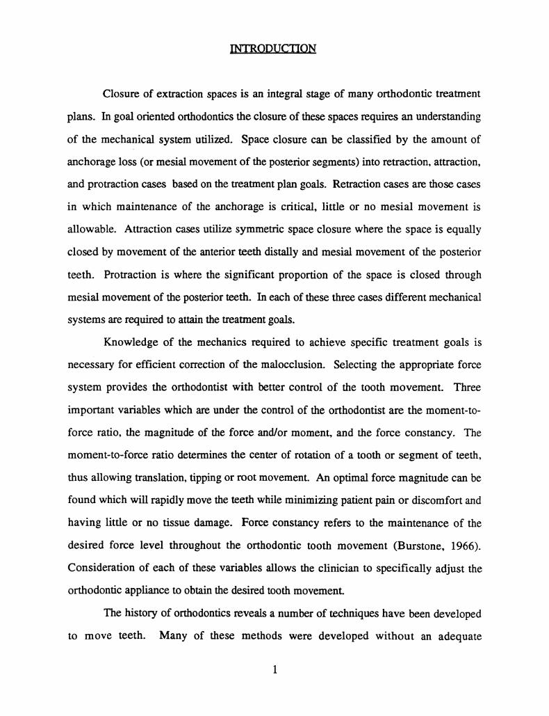
Closure of extraction spaces is an integral stage of many orthodontic treatment
plans. In goal oriented orthodontics the closure of these spaces requires an understanding
of the mechanical system utilized. Space closure can be classified by the amount of
anchorage loss (or mesial movement of the posterior segments) into retraction, attraction,
and protraction cases based on the treatment plan goals. Retraction cases are those cases
in which maintenance of the anchorage is critical, little or no mesial movement is
allowable. Attraction cases utilize symmetric space closure where the space is equally
closed by movement of the anterior teeth distally and mesial movement of the posterior
teeth. Protraction is where the significant proportion of the space is closed through
mesial movement of the posterior teeth. In each of these three cases different mechanical
systems are required to attain the treatment goals.
Knowledge of the mechanics required to achieve specific treatment goals is
necessary for efficient correction of the malocclusion. Selecting the appropriate force
system provides the orthodontist with better control of the tooth movement. Three
important variables which are under the control of the orthodontist are the moment-to-
force ratio, the magnitude of the force and/or moment, and the force constancy. The
moment-to-force ratio determines the center of rotation of a tooth or segment of teeth,
thus allowing translation, tipping or root movement. An optimal force magnitude can be
found which will rapidly move the teeth while minimizing patient pain or discomfort and
having little or no tissue damage. Force constancy refers to the maintenance of the
desired force level throughout the orthodontic tooth movement (Burstone, 1966).
Consideration of each of these variables allows the clinician to specifically adjust the
orthodontic appliance to obtain the desired tooth movement.
The history of orthodontics reveals a number of techniques have been developed
to move teeth. Many of these methods were developed without an adequate
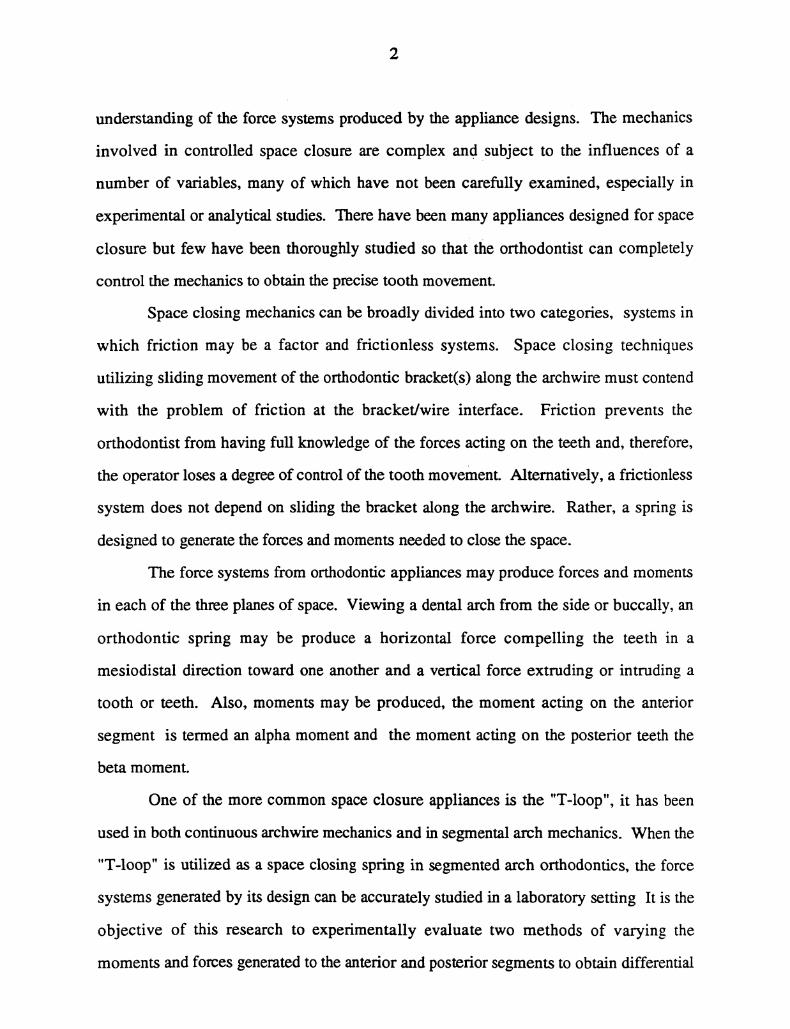
understanding of the force systems produced by the appliance designs. The mechanics
involved in controlled space closure are complex and subject to the influences of a
number of variables, many of which have not been carefully examined, especially in
experimental or analytical studies. There have been many appliances designed for space
closure but few have been thoroughly studied so that the orthodontist can completely
control the mechanics to obtain the precise tooth movement.
Space closing mechanics can be broadly divided into two categories, systems in
which friction may be a factor and frictionless systems. Space closing techniques
utilizing sliding movement of the orthodontic bracket(s) along the archwire must contend
with the problem of friction at the bracket/wire interface. Friction prevents the
orthodontist from having full knowledge of the forces acting on the teeth and, therefore,
the operator loses a degree of control of the tooth movement. Alternatively, a frictionless
system does not depend on sliding the bracket along the archwire. Rather, a spring is
designed to generate the forces and moments needed to close the space.
The force systems from orthodontic appliances may produce forces and moments
in each of the three planes of space. Viewing a dental arch from the side or buccally, an
orthodontic spring may be produce a horizontal force compelling the teeth in a
mesiodistal direction toward one another and a vertical force extruding or intruding a
tooth or teeth. Also, moments may be produced, the moment acting on the anterior
segment is termed an alpha moment and the moment acting on the posterior teeth the
beta moment.
One of the more common space closure appliances is the "T-loop", it has been
used in both continuous archwire mechanics and in segmental arch mechanics. When the
"T-loop" is utilized as a space closing spring in segmented arch orthodontics, the force
systems generated by its design can be accurately studied in a laboratory setting It is the
objective of this research to experimentally evaluate two methods of varying the
moments and forces generated to the anterior and posterior segments to obtain differential
tooth movement in a laboratory setting and to provided specific clinical assessments
permitting the orthodontist to adjust the appliance to meet their treatment goals.
Specifically, the present study will experimentally compare the effects of varying the
angulation of the arms of the "T-loop" and varying the position of the spring between the
segments. It is hypothesized that the alpha and beta moments can be differentially
controlled by either of these methods.
LITERATURE REVIEW
Mechanics of Tooth Movement
The orthodontic movement of teeth is accomplished by the application of forces
on the teeth, generally through the use of brackets, wires springs and elastics. The type
of tooth movement which occurs is dependent upon the force system utilized. The
movement can be translational (bodily), rotational, or a combination of each, as
determined by the applied force system. Translation is pure bodily movement in the
direction of the line of action of a force applied at the center of resistance. The center of
resistance is analogous to a center of gravity or a center of mass, a force applied at the
center of resitance will produce no rotation. The center of resistance for a given tooth is
dependent of the root length, root surface area, and alveolar bone height. Any force
which does not pass through the center of resistance will produce some rotation due to the
moment of the force. The magnitude of this moment is equal to the force multiplied by
the perpendicular distance of line of action of that force to the center of resistance.
Purely rotational movement can only be accomplished by a couple, which is two forces of
equal magnitude with parallel noncolinear lines of action and opposite directions. The
orthodontist is able to control the type of tooth movement by proper application of the
forces and moments produced by the orthodontic appliance (Smith and Burstone, 1984).
The concept of static equilibrium is also important. Static equilibrium relates to
Newton’s first law of motion, "Everybody continues in its state of rest, or of uniform
motion in a straight line, unless it is compelled to change by the state of forces impressed
on it". For any body in equilibrium the sum of the forces and moments acting upon it is
zero, Knowledge of the magnitudes and directions of the forces and moments produced
by the wire in equilibrium aids the orthodontist in predicting the tooth movement.
Prediction of orthodontic tooth movement may be accomplished if one keeps the
above mechanical principles in mind. For a particular malocclusion, the orthodontist may
5
accurately predict and treat the problem by following these steps" 1) problem
identification, 2) establish the required direction and center of rotation of the tooth
movement, 3) determine the necessary force system to achieve the required direction and
center of rotation, 4) evaluate the equilibrium state of the appliance, 5) appliance
selection (material and shape), and 6) appliance activation. This systematic approach to
correction of a malocclusion permits individualized, goal-oriented treatments.
Moment-to-Force Rttios and enr 0f Rotation
Description of tooth movement is often based on the concept of the center of
rotation. Pure translatory movements are considered to have a center of rotation an
infinite distance away from the center of resistance and pure rotational movements occur
when the center of rotation is at the center of resistance. All other tooth movements
result from a center of rotation somewhere in between these two points.
Determination of the center of rotation for various force systems have been
studied theoretically and experimentally. Burstone and Pryputniewicz (1980) used laser
holography to determine the required force systems placed on a maxillary centr incisor
to produce different centers of rotation in an in vitro model. Their study used a 10:1
model of a maxillary central incisor loaded with a labiolingual force of 200g. They
found that center of resistance of the tooth was about one third of the distance of the
alveolar crest to the apex. The experimentally determined moment-to-force ratio for
translation was 9.9:1, for tipping about the apex, 7.1" 1, and for tipping about the incisal
edge, 11.4:1. These values were in agreement with their theoretically predicted values.
Tanne, Koenig, and Burstone (1988) investigated the relationship between
moment-to-force ratios and centers of rotation by use of the .finite element method. A
three-dimensional model of a maxillary right central incisor Was modeled. The center of
resistance and centers of rotation for various moment-to-force ratios applied at the center
of the crown were found. They found that a M/F ratio of 6.52:1 for tipping about the
apex, 8.39:1 for translation, and 9.53:1 for root movement. It was determined that even
small changes in the M/F ratio could produce large changes in the center of rotation.
Kusy and Tulloch (1986) analyzed moment-to-force ratios at the bracket and at
the center of resistance in relation to the tooth movement produced. They concluded that
the only accurate method for determining the tooth movement was by evaluation of the
moment-to-force ratio at the center of resistance. At the center of resistance all the
moments applied to the tooth by the force system are included.
The studies examining the relationship of the moment-to-force ratio indicate that
it is very important for the orthodontist to be aware of this variable during treatment.
Small errors in the moment-to-force ratio may lead to tooth movements which are not
desirable for a given clinical case. Also, incorrect assumptions regarding the moment to
force ratio may lead to the use of improper mechanical systems. Clearly, it is advan-
tageous for the orthodontist to have the ability to adequately control this aspect of a force
system.
Qptimum Ol’hodoni Forces
The magnitude of the applied orthodontic force is important for efficient tooth
movement. Various hypotheses have been developed relating force magnitude to the rate
of tooth movement. Hixon, et al (1970) studied the rote of bodily tooth movement as a
function of the applied force. The subjects were all children requiring extraction of four
first premolars and distal retraction of the canines. Rigid segments were placed (.045"
stainless steel) in an attempt to prevent tipping movement of the canines. They found
that even with rigid wires flexion still occurred resulting in tipping movement in some
cases. Great variation in the root surface area, time of-beginning tooth movement, and
rates of tooth movement were observed. The magnitude of these differences were greater
than the differences in the magnitude of force that can be controlled by the orthodontist.
They felt that their results did not support a differential force theory (posterior segments
will move less because of increased root surface area compared to a canine tooth).
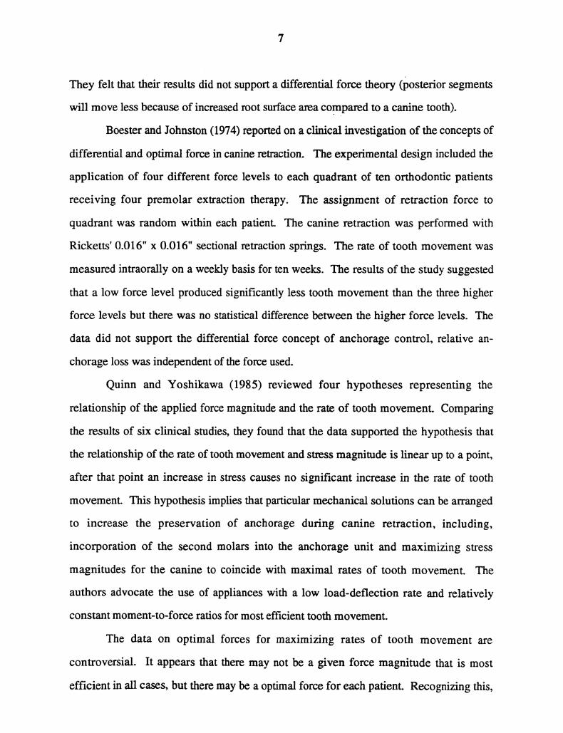
Boester and Johnston (1974) reported on a clinical investigation of the concepts of
differential and optimal force in canine retraction. The experimental design included the
application of four different force levels to each quadrant of ten orthodontic patients
receiving four premolar extraction therapy. The assignment of retraction force to
quadrant was random within each patient. The canine retraction was performed with
Ricketts’ 0.016" x 0.016" sectional retraction springs. The rate of tooth movement was
measured intraorally on a weekly basis for ten weeks. The results of the study suggested
that a low force level produced significantly less tooth movement than the three higher
force levels but there was no statistical difference between the higher force levels. The
data did not support the differential force concept of anchorage control, relative an-
chorage loss was independent of the force used.
Quinn and Yoshikawa (1985) reviewed four hypotheses representing the
relationship ofthe applied force magnitude and the rate of tooth movement. Comparing
the results of six clinical studies, they found that the data supported the hypothesis that
the relationship of the rate of tooth movement and stress magnitude is linear up to a point,
after that point an increase in stress causes no significant increase in the rate of tooth
movement. This hypothesis implies that particular mechanical solutions can be arranged
to increase the preservation of anchorage during canine retraction, including,
incorporation of the second molars into the anchorage unit and maximizing stress
magnitudes for the canine to coincide with maximal rates of tooth movement. The
authors advocate the use of appliances with a low load-deflection rate and relatively
constant moment-to-force ratios for most efficient tooth movement.
The data on optimal forces for maximizing rates of tooth movement are
controversial. It appears that there may not be a given force magnitude that is most
efficient in all cases, but there may be a optimal force for each patient. Recognizing this,
it is important that the orthodontist have a variety of methods available in order to adjust
the force systems for individualized treatments.
Loop Design on Canine Retraction
The closure of extraction spaces orthodontically can be accomplished with a
variety of different methods. Space closure techniques involving sliding mechanics in
which the orthodontic bracket is moved along a continuous archwire are widely used.
The most common mechanisms include the use of either elastics or coil springs as means
to obtain a driving force to close interdental spaces. These techniques have limitations,
especially problems with wire/bracket friction, high load/deflection rates, and a lack of
anchorage control. Alternatively, several loop systems have been developed. These
systems provide the driving force through activation of the loop, this removes the effects
of friction. These types of appliances may incorporate bends in the wire which increase
anchorage control by providing differential moments on the anterior and posterior
segments. Also, loops may be designed with a lower load/deflection rate, providing
better force constancy.
Poul Gjessing (1985) designed a canine retraction spring for use in the sectional
arch technique. This spring was developed on the basis of a series of theoretical
considerations intended to create an optimal force system for controlled canine retraction.
The spring was constructed from 0.016" x 0.022" stainless steel wire with the principle
element being a double ovoid loop of 10 mm in height. A "sweep" bend was
incorporated distally to avoid unwanted side effects on the second premolar. An
antirotation moment was also added to prevent distal-in rotation of the canine.
Gjessing bench tested different canine retraction spring designs in an electronic
spring tester apparatus. The finalized spring utilized many design elements incorporated
to maximize efficient tooth movement with a minimum of unwanted side effects. A
double ovoid loop was the predominant active element. This loop extended 10 mm
apically reducing the load/deflection rate of the spring. Activation of this loop caused
tipping of the shorter hodzontal arm attached to the canine which increased the moment
acting on this tooth. The greatest amount of wire was in the vertical direction which
further maximized the reduction of the horizontal load/deflection rate. Further, a
minimum of horizontal wire increased rigidity in the vertical plane. A smaller loop
placed more occlusally lowered levels of activation insertion into the brackets. The
mesial and distal extensions were angulated horizontally and vertically to provide
differential alpha and beta moments as well as an antirotation moment.
Bench testing of this spring found an initial force of 180g at an activation of 3 mm
with a force decay of 45g/mm. Full deactivation of this force occurred at between 3 and
4 mm. The alpha moment-to-force ratios were reported as approximately 9:1 at initial
activation (3 mm), rising to approximately 11-1 with 1.5 mm deactivation and greater
than 16" 1 at 3 mm deactivation. The beta moment-to-force ratios started at 4"1 and
climbed to approximately 8:1 at 3 mm deactivation. Incorporation of a "sweep" bend in
the distal arm resulted in decreased beta moments. It was clinically observed that the beta
moment was delivering too great of a moment to the second premolar resulting in an
undesirable degree of mesial root movement.
The canine retraction spring designed by Gjessing was used in a clinical study
comparing maxillary canine retraction with a spring to retraction with sliding mechanics
(Ziegler and Ingervall, 1989). Twenty-one subjects were included in the study, each
subject had one canine retracted with the spring while the other side had retraction with
sliding mechanics using 0.018" stainless steel arch wire and elastic chains. They found
that the spring provided faster retraction of the canine with less tipping compared to the
sliding mechanics. However, they found that space closure with the spring may result in
more rotational side effects. It was concluded that, overall, the spring system was
superior to sliding mechanics due to its more rapid tooth movement with less tipping in
spite of problems with rotation of the canine because correction of rotations is easier than
10
canine root correction and is less taxing on the anchorage. They recommended increasing
the antirotational moment to minimize this side effect.
Gjessing’s canine retraction spring may be an to effective appliance for
orthodontic space closure. The reported force system does, however, reveal limitations in
its design. First, the horizontal force decays over a distance of 3 mm to values which
may be too low for efficient tooth movement. This requires several re-activations of the
spring to close a typical extraction space of seven millimeters. Also, the reported initial
beta moment-to-force ratios (4:1 without the "sweep" bend, about 1-1 with the "sweep"
bend) make effective anchorage control questionable. Further, the vertical forces and
side effects due to differential alpha-beta moments are not reported and may be of clinical
significance.
Haskell, Spencer, and Day (1990) introduce an auxiliary retraction spring for use
in continuous arch treatment. They designed and modified an auxiliary space closure
spring utilizing finite-element analysis for use in retraction, attraction, and protraction
cases. They designed separate springs for the maxillary and mandibular arches. The
mandibular spring included double vertical loops with helices and an additional helix in
the anterior portion. The maxillary spring had a single vertical loop with a helix and it
also and the additional anterior helix. Both springs were specially fabricated by Rocky
Mountain Orthodontics (Denver, Colorado) from 0.017" x 0.022" heat treated Elgiloy. A
special canine bracket was designed with an auxiliary tube placed gingivally for spring
insertion. These appliances had three important angles incorporated for differential
moment control. They reported the differential angulations for each on the basis of the
type of tooth movement desired (retraction, attraction, or protraction). The results of
finite-element analysis indicated an increasing moment-to-force ratio with spring
deactivation from approximately 5"1 to greater than 15"1 for both springs over a
deactivation range of 4 mm to less than 1 mm. The reported results were for only maxi-
mum reciprocal attraction springs, The alpha and beta moments were of similar
11
magnitude. The authors recognize the potential vertical forces present in their appliance
design and the reported values at 4 mm activation for the retraction spring (126g) may be
high enough to generate clinical effects. It is their postulation that the main continuous
arch wire prevents the vertical side effects associated with unbalanced moments.
Haskell, et al, consider their design superior to present segmented arch techniques
because it incorporates the "fail-safe" mechanism of the continuous arch while permitting
the use of differential force systems for space closure. This design combines sliding
mechanics with precalibrated springs. Also they consider their system to be more "user-
friendly" through its use of sliding mechanics and simpler design compared to the
multiple components of the segmented arch technique.
The use of the above auxiliary springs in conjunction with a continuous arch wire
may be an improved method of sliding mechanics for space closure. Their design is
limited by the effects of bracket/wire friction during space closure which may require
large horizontal forces for efficient tooth movement. Friction may produce unwanted
side effects, taxing anchorage units and possibly hindering the clinicians control of the
tooth movement.
The segmented arch technique, as developed by Burstone, uses "T-loop" springs
for space closure. The "T-loop" spring incorporates design considerations intended to
provide optimum mechanical systems during space closure. The segmentation of the arch
into anterior and posterior portions creates the equivalent of a two tooth system, allowing
it to become a statically determinate system. The increased interbracket distance
(between canine and first molar)enables long activations which lowers the load
deflection rate. Further, the use of segments permits prefabrication of calibrated
orthodontic springs (Burstone, 1962).
Experimental and theoretical analysis of space closing loops led to the design of
the present "T-loop". Force systems from vertical loops were analyzed (Burstone and
Koenig, 1976). The results of these studies showed that the higher the vertical loop the
12
larger the moment and smaller the force from the spring. Higher vertical loops also had
greater ranges of activation without permanent deformation. Increasing the horizontal
dimension of the loop had the effect of decreasing the moment-to-force ratio, decreasing
the forces and the moments at yield, but the moment-to-force ratio was not as greatly
effected by horizontal changes compared to vertical changes.
The results of the studies on vertical loops indicated that a "T-loop" may be an
improved spring design. The "T" shape of the space closing spring places additional wire
apically within the loop, this raises the moment-to-force ratio while also decreasing the
load deflection rate. Increasing the amount of wire in the gingival portion of the loop
increases the moment-to-force ratio so that it approaches the vertical height of the loop.
The moment-to-force ratio can never be greater than the vertical height of the "T-loop"
unless further design modifications are incorporated.
To further optimize the design of anterior and canine retraction springs, the effects
of loop centering were studied. Comparison of off-centered vertical loops was done by
using a ratio of the length of the wire from the center of the loop to its distal end over the
complete length of the wire. This analysis showed that asymmetric placement had a
strong effect on the force system delivered by the spring. Even small off-center
placements can produce significant vertical forces through altering the alpha and beta
moments as well as changes in the horizontal forces. The moment was found to be
greater at the end closer to the loop, for example, moving the loop mesially generates a
greater alpha moment.
The angulation of the horizontal legs of the vertical loop were also studied.
Angulating the horizontal legs (gable bends)produced significant changes in the force
systems generated by the vertical loop. However, because even small variations in spring
geometry caused significant changes in the moment-to-force ratio, one must be very
cautious about making any generalizations unless the spring shape is very accurately
determined (Burstone and Koenig, 1976).
13
The "T-loop" spring was refined for use in the segmented arch technique
(Burstone, 1982). Differential space closure is achieved through variations in the force
system between the anterior and posterior segments. Specific predetermined geometries
were developed for producing the desired force systems needed for the individual needs
of each case. These spring geometries were designed for narrow ranges of use dependent
upon both type of tooth movement and the interbracket distance. These springs were
constructed from beta-titanium wire which has improved material qualifies compared to
conventional stainless steel wires.
Two important considerations in the design and use of "T" springs is the
preactivation spring geometry and the loop placement (centricity) between the
attachments. The angulations of the mesial and distal arms of the spring are varied to
obtain the appropriate alpha and beta moments. The large interbracket distance aids in
reducing the deviations from the desired force system due to errors spring shape. Spring
centricity is also reported as being important, especially reciprocal attraction cases. For
the spring designs presented, it is recommended that the loop be centrally placed in cases
where the anterior and posterior teeth move equal amounts. If the posterior teeth are to
be held, the spring is placed nearer the anterior teeth, the loop is placed posteriorly if the
anterior teeth are to be maintained (Burstone, 1982).
A study of space closure with "T-loop" retraction springs in adult patients was
done by Manhartsberger, Morton, and Burstone (1989). The springs were tested in the
laboratory with consideration to the special of orthodontic treatment in adult patients. In
adult patients with periodontal bone loss there must be changes in the force system due to
changes in the crown-m-root ratios. Additionally, the springs tested in this study had
curvature to the mesial and distal arms as opposed to discrete angular bends for the
creation of differential alpha and beta moments. Specific recommendations for changes
in the "T-loop" design include a reduction in the magnitude of the force level and an
increase in the moment-to-force ratio. This can be achieved through changing the cross-
14
section of the wire from 0.017" x 0.025" TMA to 0.016" x 0.022"TMA and/or changing
the amount of activation of the spring. The moment-to-force ratio can be increased by
increasing the angulation bends (Manhartsberger, Morton, and Burstone, 1989).
Analytical and Experimental Studies of Space Closing Loops
Finite element method is a useful technique for stress analysis of orthodontic
appliances. This is a powerful method for determining the force systems from complex
spring geometry’s and results may be compared to experimental findings for verification.
Yang and Baldwin (1974) examined space closing loops of two designs, a vertical loop
and a double helical space closing spring used in the segmented arch technique. They
compared the results of their finite element method to experimental testing of these
springs. The theoretical results of the finite element analysis closely matched the
experimental results. The magnitude of the moment changed considerably with each
millimeter of activation of the vertical loop. The vertical loop also displayed a nearly
constant moment-to-force ratio. The helical spring displayed a very slight change of the
moment for each millimeter of activation. With the helical spring it is possible to have an
increasing moment-to-force ratio as the spring deactivates. The findings suggested that
the helical closing spring offered a desirable force system enabling space closure and root
correction with the same device.
They concluded that this spring had several advantages compared to the vertical
loop. In addition to producing a more efficient force system, the compactness of the
spring compared to a 10 mm vertical loop may be more tolerable by the patient. The
helical spring provided a more constant application of force. It was also easier to gauge
the activation force by measuring the distance between the legs of the loop. In the
vertical loop, angular rotations of the ends of the vertical arms produced large changes in
the applied force.
15
Sachdeva (1985) experimentally studied the force systems produced by TMA "T-
loop" retraction springs in a laboratory setting. This study examined the effect of
interbracket distance, loop placement, and design on the force systems produced by "T-
loop" space closure springs. Specifically, retraction, attraction, and protraction springs
were compared over four interbracket distances and the effects of placement on attraction
(symmetric) "T-loop" springs were analyzed.
The significant conclusions drawn from Sachdeva’s investigation were- 1) "T-
springs" without preactivation bends are not effective for space closure, 2) Spring design
must be varied for different interbracket distances for optimal mechanics, precalibrated
spring designs for four interbracket distances were presented, 3) the effects of spring
placement and interbracket distance on the load deflection rate were not significant while
preactivation bends do have an effect of lowering the 10ad deflection rate, 4) off-centered
placement of the spring resulted in changes in the moment magnitudes and with
increasing eccentricity there was increased differential in the alpha and beta moments, 5)
the principle factors governing the moment-to-force ratio of the "T-springs" were the
activation moment, moment/displacement rate, the residual moment, and the load de-
flection rate of the appliance, 6) greater angular activation bends were necessary as the
interbracket distance increased.
Faulkner, Fuchshuber, Haberstock, and Mioduchowski (1989) considered the
effects of several parameters of the force system produced by "T-loop" retraction springs.
They used both finite element analysis and experimental procedures in their evaluation of
various spring designs. They compared the effects of spring height, activation angle,
non-centered placement, and the addition of helices on the force systems of "T-loop"
retraction springs. From their results, they concluded: 1) increasing spring height
resulted in a smaller relative decrease in moment compared to horizontal force, resulting
in increased moment-to-force ratios as loop height increased, 2) asymmetric changes in
the alpha and beta activation angles did not produce significant changes in the horizontal
16
force but did have a considerable effect on the alpha and beta moments creating
substantial vertical forces of clinical significance, 3) non-centered placement of the loop
also generates vertical forces by significantly altering the moment magnitudes, 4) the
addition of helices at the top of the spring have only small effects on the force system and
therefore are of no practical value.
The study by Faulkner, et al (1989) provided insights into the effects of various
parameters on retraction spring force systems. However, the experimental design used
prevented easy clinical application of their results. First, the specific geometry of a
standard (baseline) spring were not given limiting comparability of the force system
changes as a result of experimental manipulation. Second, the variation of the differential
alpha and beta activation angulations was not systematic making it difficult to recognize
trends related to the changing force systems. Finally, the effects of non-centered
placement of the spring are not clear due to an apparent error in the presentation of the
results.
RATIONALE
Based on previous studies, it can be seen that the force systems generated by
various space closure mechanisms are of interest to the orthodontist. Accurate
knowledge of the force system produced by the orthodontic appliance is important in the
optimal design of a space closure spring. Factors influenced by spring design under
control of the orthodontist are the moment-to-force ratio, force and moment magnitude,
and force constancy. Therefore, an understanding of the techniques that an orthodontist
may utilize to alter these factors to obtain an ideal force system are beneficial in
determining individual patient treatment/mechanics plans.
The force systems from "T-loop" springs have been previously studied, however,
several parameters require further investigation. A systematic approach to the effects of
spring placement on the forces produced by "T-loops" has not been done which can
readily provide the clinician with data permitting an accurate prediction of the force
system changes due to their position changes. An investigation of the effects of off
centered placement and asymmetric geometry, on the force system would provide the
orthodontist with information regarding "T-loop" mechanics and methods for reliably
adjusting these parameters for individualized treatment needs.
Previous comprehensive studies of "T-loop" springs have utilized discretely
positioned angled bends in the mesial and distal anaas in order to alter the moment
magnitude. Manhartsberger, et al (1989) used curvature to these arms for generating the
moments. Advantages of this spring design change include production of a more
reproducible force system, less permanent deformation, a decreased effect of small errors
in geometry,, and increased ease of insertion and spring re-activation. The present study
incorporated this design change into the springs examined.
17
GENERAL OBJEC.TIVES
The purpose of this study was to determine the effects of different pre-activation
bends and positioning on the force systems produced by segmented "T-loop" orthodontic
space closure springs. It is hypothesized that the force system can be altered by changing
the angle of the preangulation bends by and by the mesiodistal position of the "T-loop".
Further, it was hypothesized that the magnitude of the difference between the alpha and
beta moments will increase with increasing differences in the angulations of the anterior
(alpha) and posterior (beta) ends of the spring. The alpha-beta moment differential will
also increase with increasing eccentricity in spring positioning.
Specific Objectives
The specific objectives of the present study were:
1) To experimentally determine the effects of altering the mesio-distal position
(centricity) of symmetric "T-loops" on the force systems produced, specifically the
changes in the alpha-beta moment differential.
2) To experimentally determine the effects of asymmetric angulations of the
anterior and posterior arms of centered "T-loops" (orthodontic space closing springs) on
the force systems produced, specifically the changes in the alpha-beta moment
differential.
3) To compare the force systems produced by each of the above methods to
determine which method is a more predictable procedure for orthodontic space closure.
18
THE RESEARCH PLAN
Materials and Methods The Exoedmental ADoamtus
The experimental studies were be performed on the spring tester located in the
Bioengineering laboratory of the Department of Orthodontics, School of Dental
Medicine, University of Connecticut Health Center (Solonche, Burstone, and Vanderby,
1977). This device measures uniplanar forces and moments of orthodontic appliances
which are statically indeterminate. Forces and moments are converted into linear and an-
gular displacements respectively, and then transduced into electrical signals. These
analog signals are then converted into digital signals which are received by a computer
for analysis. Figures 1 and 2 provide schematic diagrams of the forces and moments
measured by the apparatus.
To measure the force system from an orthodontic appliance, the appliance is
mounted in two chucks on the spring tester. Each chuck is attached to an angular
displacement transducer (TRANS-TEK, Ellington, CT) whose movable member is
restrained by a torque element, therefore the angular displacement sensed by each
transducer is proportional to the torque applied by the orthodontic spring. This provides
measurements of the moments produced.
To measure the forces, one chuck is mounted on a cantilever beam whose vertical
dispacements are proportional to the force delivered by the spring and is monitored by a
LVDT displacement transducer (TRANS-TEK). The second chuck is mounted to a
movable carriage (Velmex, E. Bloomfield, NY) whose motion can be controlled by a
variable speed motor and monitored by another LVDT displacement transducer. This
displacement transducer measures forces along the horizontal axis. The movable carriage
activates the appliance permitting measurement of the forces delivered.
The data from the transducers are fed into a computer for processing. The
computer program calculates the forces and moments produced by the appliance. The
19
20
data provided includes the horizontal and vertical forces as well as the moments felt at
each chuck, A calculation of the equilibrium condition is also performed which verifies
the calibration of the device.
This equipment simulates a two-tooth or two-segment situation (the orthodontic
springs are attached at two points). This model is equivalent to the clinical use of these
"T-loops in segmented arch orthodontic techniques.
Materials and Methods Apparatus Calibration
The spring tester was calibrated prior to the experimental tests using dead weights
of known values. Horizontal and vertical forces, alpha and beta moments were applied to
the apparatus attachments and the voltage output from the transducers was compared to
unloaded voltages for each sensor. The difference between the loaded and unloaded
readings provide values which are proportional to the applied loads. These values are
multiplied by calibration constants to convert the data to units of force (grams), and
moments (grams*millimeters). These calibration constants were adjusted to obtain
accurate readings. The calibration tests were regulary repeated throughout the data
collection period to insure accuracy.
Materials and Methods- The. "T-10op" Sp.ring
The orthodontic appliances to be tested were space closure springs of a "T-loop"
design as utilized in segmented arch orthodontics. These springs are prefabricated
(Ormco Corp., Glendale, CA) from .017" x .025" TMA wire. Figure 3 depicts a "T-loop"
and its dimensions prior to the placement of any preactivation bends. The alpha or
anterior portion of the spring is recognizable by its longer vertical arm. The beta or pos-
terior part of the spring has the shorter vertical arm. The vertical offset between the
alpha and beta arms compensates for the difference in the levels between the canine
bracket and the auxiliary tube of the Burstone molar bracket.
21
Materials and Methods- Preactivation Bending of The_Springs
Preactivation bends were placed into the "T-lo0P" in order to provide alpha and
beta moments which are necessary to obtain differential tooth movement of the mesial
and distal segments. Previous studies used preactivation geometries which have discrete
angled bends in the arms of the "T-loop". Prelimary work completed in the University of
Connecticut Orthodontic Bioengineering laboratory has indicated that curvilinear bending
of these arms is preferrable. This geometry provides less premanent deformation.
Further, the arc-form of the arms makes reactivation of the "T-loops" easier by removing
the possiblity of the angled bend(s) binding in the auxiliary tube of the molar bracket.
The present study used the "T-loops" with these curved preactivation bends.
Preactivation bends were made on each spring with orthodontic light wire pliers.
Templates were designed for each spring geometry. Gradual, smooth curvature of the
leg(s) of the spring within that portion of the spring between the T-loop and the bracket
and a neutral position of zero millimeters were specific considerations in the design in
each template. The neutral position is defined at the position of the spring "with the
activation moments placed on the spring, the neutral position is defined as the position of
the helices (or the vertical arms of the spring) when the force is zero" (Burstone and
Hanley, 1985). With the present spring design, the neutral position should have the
vertical arms of the loop just touching one another (neutral position equal to zero). The
angulation of the bends were measured as the angle between the horizontal aspect of the
"T-loop" and the bent leg. The horizontal part of the loop provided a reference line
which was parallel to the legs of the spring prior to any bending.
In order to obtain the proper shape of each spring, each angulation must be over
bent and the spring then trial activated by hand. This was done by grasping each end of
the spring with orthodontic pliers at the point where it would be attached to the apparatus
and opening the spring to the full activation of six millimeters while maintaining
parallelism of the alpha and beta (anterior and posterior) sring legs. Following trial
22
activation, the springs were compared to the templates and the necessary adjustments
were made to create the proper spring geometry. The trial activation procedure was
repeated and adjustments were made until each spring matched the appropriate template.
Every effort was made to minimize overworking the orthodontic wire by too frequent
bending or bending angles too acutely.
Materials and Methods- Sodn Positionin
The range of activation of the springs for was six millimentrs for this study. The
interbracket distances were from seventeen millimeters (zero millimeters activation) to
twenty-three millimeters (full activation). These distances were selected as
approximations of typical interbracket distances between a permanent first molar and
canine. The distance from the inner edge of the attachments to the "T-loop"’s center
(whre the vertical legs touched) was measured with electronic calipers which were
accurate to 0.01 millimeters.
The Experiments .Part I Symmetric Geometry_. Centered Position
For this experiment, the springs were designed with equal angulations to the alpha
and beta arms. Also, these springs were centrally positioned between the anterior and
posterior attachments, at zero millimeters activation the distance from the center of the
"T-loop" to either attachment was 8.5 millimeters. The angulations were varied from
zero to 70 degrees. Figure 4 shows the templates utilized for bending the springs. These
springs of each angulation were made and three trials for each spring were done. This
provided 72 separate trials (nine trials for eight different anguladons). Each spring was
activated six millimeters for each trial.
23
The Experiments .Part II- Syrnem.’c Springs. Off-cen_tered Positioning
Based on data gathered from the previous experiment, a spring template was
designed to deliver equal and opposite moments at full activation (six millimeters) with a
moment-to-force ratio equal to six, Figure 5 provides a template of this spring. This
spring had different angulations for the alpha and beta arms due to the one millimeter
offset in the vertical dimensions of the "T-loop". Three springs were fit to this template.
Each spring was tested three times at positions of, centered, 1, 2, 3, and 4 millimeters
toward each the anterior and posterior attachments. A total of 81 individual tests were
performed in this part.
The Experiments .Part III Asymmetric Geometry.. Centered Positioning
To determine the effect of unequal angulation of the bends, asymmetric springs
were designed. For one set of springs the alpha angulation was kept at 75 degrees and the
beta angualtion varied from 0, 15, 30, 45, and 60 degrees. Three springs of each
geometry were fabricated for a total of fifteen springs of each geometry. The second set
of springs reversed the angulations, the beta angualtion was kept at 75 degrees and the
alpha angulation varied from 0, 15, 30, 45, and 60 degrees. A total of 15 springs were
also tested in this geometry. For this experiment, a total of 90 separate trials were done.
In all cases the springs were centered between the attachments in a manner similiar to the
technique used in Part I. Figures 6 and 7 are templates for these springs.
Daha Collection
The force systems from each spring were measured on the spring tester. Each
spring was placed and tightened into proper position on the test apparatus with an initial
interbracket distance of seventeen millimeters. The spring was activated by the
motorized carriage to the full six millimeter activation and returned to the neutral position
(seventeen millimeter interbmcket distance). The carriage moved at an approximate rate
24
of one millimeter per 50 seconds. Readings of the horizontal force, vertical force, alpha
moment and beta moment were taken at 0.5 millimeter intervals. The data was complied
by the computer and a printout of the results was obtained. The output data included each
of the above listed measurements at the 0.5 millimeter intervals as well as the alpha and
beta moment-to-force ratios, the force deflection rate and a sum of the moments. The
sum of the moments provided an assessment of the overall accuracy of the measurements
(with perfect calibration, the sum of themoments would equal zero). When the sum of
the moments was excessively large (greater than 250 gram*millimeters for the majority
of the data samples of a trial), the trial was redone. This measurement was also used as
an indicator for deciding when to recalibmte the test equipment.
RESULTS
Part I: Symmetric Geometry_. (erered Position
Tables 1 through 8 present the overall results. These tables list the experimentally
observed means and standard deviations for the alpha moment, beta moment, horizontal
force, and vertical force. Also listed are the alpha moment-to-force ratio, the beta
moment-to-force ratio, the force deflection rate, and the ratio of the moments (alpha
moment/beta moment).
The magnitude of the alpha and beta moments were found to be dependent on the
angulation of the preactivation bends as well as the amount of activation. These results
are represented in Figures 8, 9, 10, and 11. By multiple linear regression analysis,
activation and angulation were found to explain a significant amount of the variation on
the magnitudes of each of the moments (F-rafiOalpha = 6383.5, p. = 0.000, F-ratiobeta =
7250.3, p. = 0.000). The moments increased with increasing activation and angulation.
These models capture over 90% of the variation in the magnitude of the alpha and beta
moments (R2 = 0.9 for both models)The multivariable statistical analyses are
summarized in Table 28 for the alpha moments and Table 29 for the beta moments.
Comparison of the parameter estimates for the alpha and beta moments indicates
that the beta moment increases more for an increase in activation and it also increases
more for an increase in the angulation. This is sexn in the greater parameter estimates (or
slopes) of the regression model (parameter estimates:, Acfivationalpha = 126.6,
Angulafionalpha = 14.7, Activationbeta = 187.3, Angulafionbeta = 18.8) for the beta
moment than the alpha moment.
The horizontal force was found to be dependent on both the activation and the
angulation (F-ratio = 10806.3, p. = 0.000). The force increases with increasing
activation. Also, the horizontal force was found to be inversely related to the angulation,
the force decreased with increasing angulation (parameter estimate, activation = 66.9, t=
25
26
144.8, p. = 0.000; parameter estimate, angle = -1.0, t = -25.3, p. = 0.000). Of the two,
activation had the greater effect on the magnitude of the horizontal force. The coefficient
of determination (R2) was 1.0 for this model. Figures 12 and 13 depict these results and
Table 30 summarizes the statistical analysis.
There was the greatest variation found in the vertical forces generated from
springs with symmetric geometry and centered positioning. The variation as represented
by the standard deviations (see Tables 1 through 8) was a large proportion of the
observed means. The vertical force was dependent on both the activation and the
angulation, with the activation having the greater role in determining the magnitude of
the force (F-ratio = 319.3, p. = 0.000; parameter estimates, Activation = 4.8, t = 4.8, p =
0.000, Angulation = 0.2, t= 13.5, p. = 0.000). The linear model based on angulation and
activation captured 40 % of the variation (R2 = 0.4). Figures 14 and 15 summarize the
findings on the vertical force, Table 31 shows the statistical results.
The ratio of the alpha moment and the beta moment, representing the moment
differential produced by the springs, was not found to be significantly related to the
amount of activation nor angulation (F-ratio = 3.8, p. = 0.023) Neither activation nor
angulation were found to be significant variables in determining the ratio of the moments
(parameter estimates, activation = -0.2, t = -1.9, p. = 0.053, angulation = 0.0, t = -1.9, p.
0.052). These results are shown in Figures 16 and 17, the statistical analysis is listed in
Table 32.
The moment-to-force ratios are given in Figures 18 and 19. These figures show an
increasing moment to force ratio with deactivation of the spring. The beta moment-to-
force ratio is higher than the alpha activation for each angulation. The moment-to-force
ratios increased with increasing angulation.
27
P0rtlI. Symmetric Springs, Off-.centeredPositioning
The .results of position on a "T-loop" with symmetric moments are presented in
Tables 9 through 17. The spring was designed to deliver equal and opposite moments
with a moment-to-force ratio equal to six. The spring was positioned 1, 2, 3, and 4
millimeters anteriorly and posteriorly from this centered position.
The effects of the positioning and activation on the alpha and beta moments are
shown in Figures 20, 21, 22 and 23. Each of the moments increased with increasing
activation. As the springs were positioned anteriorly, the alpha moments increased and
the beta moments decreased, the opposite occurred with posterior positioning. The
position had a greater effect on the change in the moments than activation. The linear
regression model using position and activation as independent variables exhibited an R2
= 0.9 for each the alpha and beta momentsfF-rafiOalpha = 3377.6, p. = 0.000; F-ratiobeta
= 3501.1, p.0.000). These results are summarized in Tables 33 and 34.
Off center positioning had a slight effect on the horizontal force. The position of
the spring was only marginally significant in determining the magnitude of the force,
(parameter estimate = 0.6, t = 2.1, p. = 0.036), while the activation was a highly
significant determinant (parameter estimate = 62.5, t = 157, p = 0.000). The horizontal
force increases linearly with increasing activation, these results are shown in Figures 24
and 25, the statistical analysis in Table 35.
The position had a significant effect on the vertical force, this was expected
because the vertical force will occur with different alpha and beta moments due to
equilibrium considerations. The vertical force also increased with increasing activation.
the whole model explains a significant amount of the variation (F-ratio = 5042.0, p. =
0.000). Off-center positioning does produce vertical forces which may be of clinical
significance. Tables 9 through 17 show the mean values of the vertical forces for each
position and activation. Figures 26, 27, and Table 36 summarize these findings.
28
The ratio of the alpha and beta moments as a function of position is shown in
Figures 28 and 29. The ratio of the moments is not si.cantly related to the activation
(parameter estimateactivation = 0.0, t =0.5, p. ---0.000), but it is dependent on the position
of the spring (parameter esfimateposition = 0.5, t = 42.8, p. = 0.0(). The ratio decreased
with positioning toward the posterior or beta segment, and it increased as it was
positioned more anteriorly. The ratio remained nearly constant (for a given position) with
changes in activation. However, the whole model was found to be significant for
describing the variation in the ratio of the moments ( F-ratio = 914.2, p. = 0.000). These
findings are summarized in Table 37. Figures 30 and 31 show the moment-to-force ratios
versus the activation.
Part III. Asymmetric Geometry_ Centered Positioning
A) Varying Alpha Angulation, Constant Beta Angulation
Tables 18 through 22 summarized the measured force systems produced by these
springs. Variation of the alpha angulation effected both the alpha moment and the beta
moment. The alpha moment was more effected by the change in alpha angulation, but
the beta moment was also determined in part by the alpha angulation (parameter
estimates, Alpha moment, angle = -22.0, t = -87.6, p. = 0.000, Beta moment = -7.1, t =
25.8, p. = 0.000). As the alpha angulation was increased, the alpha moment increased.
The beta moment decreased with increasing alpha angulation. The multiple linear
regression model with angulation and activation as independent variables was significant
for both the alpha and beta moments (F-ratiOalpha = 5379.8, p. = 0.000, F-ratiobeta =
1444.2, p. = 0.000). These results are summarized in Tables 38 and 39, and Figures 32,
33, 34 and 35.
The horizontal force was significantly determined by both the activation and the
alpha angulation (F-ratio = 6175.9, p. =0.000). As with the symmetric springs and off-
center springs, the activation was the primary determinant of the magnitude of the
29
horizontal force (parameter estimates, angulation = -0.9, t = -18.1, p. = 0.000, activation =
61.2, t = 109.7, p. = 0.000). Figures 36 and 37, as well as Table 40, show these results.
The vertical force was inversely related to the alpha angulation, as the angulation
increased, the vertical force decreased. The vertical force was in the intrusive direction
on the anterior segment. As with off-centering the vertical forces were expected due to
the different alpha and beta moments. These results are depicted in Figures 38, 39 and
Table 41 shows the statistical results.
The ratio of the alpha and beta moments was significantly related to both the
alpha angulation and the activation (F-ratio = 2859.5, p. = 0.000). Activation and
angulation both were found to be significant variables in determining this ratio. The ratio
of the alpha moment/beta moment decreased with both increasing angulation and
increasing activation. See Figures 40 and Table 42 for these results. Figures 41 and 42
show the moment-to-force ratios versus the activation.
B) Constant Alpha Angulation, Varying Beta Angulation
The effect of varying the beta angulation on the force system was similar to
varying the alpha angulation. The beta moment increased with increasing angulation and
activation (F-ratio = 2180.0, p. = 0.000). With increasing beta angulation, the alpha
moment decreased, but to a lesser degree than the change in the beta moment. More
important in determining the magnitude of the alpha angulation was the activation. See
Tables 23 to 27 for the overall results; Tables 43 and 44 for the statistical analysis; and
Figures 43, 44, 45, and 46.
With the asymmetrically shaped springs it is notable that the moment for the side
being varied (that is, the alpha moment for the springs with varying alpha angulation and
vice versa), the direction of the moment would change direction at the lower angulations
and activations. This effect was seen more strongly with the changing beta angulation.
30
The horizontal force was again determined primarily by the activation and only
minor role was played by the angulation. These results are. given in Figures 47, 48 and
Table 46.
Large vertical forces were found with these springs. The forces were in the
extrusive direction on the anterior segment. These forces increased with decreasing
angulation and decreased with increasing activation. See figures 49 and 50 and Table 46.
The ratio of the beta moment/alpha moment was determined by both the beta
angulation and the activation (F-ratio = 1805.4, p. = 0.000) This is similar to the effect of
altering the alpha angulation on the alpha moment/beta moment ratio.. See Table 47 and
Figures 51 and 52 for these results. Figures 53 and 54 show the moment-to force ratios
versus the activation.
DISCUSSION
This study demonstrates the importance of proper preactivation bends and spring
positioning in designing "T-loop" springs for controlled orthodontic space closure. The
force systems produced by the "T-loop" springs can be very effectly manipulated by
either changes in the angulation or in the position. The differences in the alpha and beta
moments is the most critical consideration because the moment magnitudes determine the
moment-to-force ratios. The moment-to-force ratios are related to the type of tooth
movement and anchorage control for the anterior andposterior segments. The moment
differential also determines the vertical forces produced by the spring. Effect control of
the moment differential will then have a great influence on the orthodontist’s ability to
obtain predictable tooth movement.
The ratio of the moments (alpha moment/beta moment) were determined by
different variables for the off-centered springs and the asymmetric angulated springs. For
the off-centered springs, the position was the only significant determinant of this ratio,
while for the asymmetric springs this ratio was determined by both the angulation and the
activation of the spring.
The amount of spring activation did not significantly influence the ratio of the
moments in the off-centerd springs. For these springs, the activation played about equal
roles for the alpha and beta moments, the position was the variable which played the
primary role in predicting the moment differential. Alternatively, the moments produced
by the asymmetric springs were influenced by the both activation and the angulation.
Further, the activation had a different effect on the alpha moment than on the beta
moment. The side of the spring with the constant angle was less effected by the angular
variations, while the angle had a greater impact on the varied side. Because the activation
effected the alpha and beta moments unequally in the asymmetric springs, it was
important in determining the ratio of these moments.
31
32
This has important clinical applications, controlling the ratio of the moments
permits predictable space closure. Maintiaining a more constant ratio of the moments
over the range of activation of the spring allows consistent control of the differential
space closure. This is the situation with the off-centered springs, the alpha-beta moment
differential is independent of the activation. For the springs with asymmetric angulation,
the ratio of the moments is both angulation and activation dependent. To obtain a
consistent ratio, one only has to monitior the position for the off-centered springs, but for
the asymmetric springs one must consider both the angulation and the activation.
While closing extraction spaces, anchorage control is obtained by producing
proper force systems. Application of unequal moments to the anterior and posterior
segments can augment the anchorage unit. Consistent production of a moment
differential is advantagous for space closure. Utilizing a spring designed to produce
equal and opposite moments at the centered position and placing it eccentrically may be a
more effective means of anchrage control than creating springs of asymmetric shapes
(angulations). This study shows that the ratio of the moments is maintainted throughout
the range of activation with off centered positioning. A postion two millimeters from the
center (toward the anchorage unit) would be sufficient for reinforcing the anchorage of
that segment. Whe the T-loop was placed two millimeters toward the anterior segment,
the alpha moment/beta moment ratio is approximately two. Doubling the alpha moment
relative to the beta moment would strengthen the anterior anchorage. A similiar result is
seen when the spring is positioned two millimeters toward the posterior, the beta moment
becomes twice the alpha moment.
The asymmetric angulation of the preactivation bends of T-loop springs may
permit these springs to be used as root correction appliances. Efficient root movement is
best achieved with the application of a moment-to-force ratio of 12 to 15/1. These
moment-to-force ratios are acheived with several of the spring shapes tested. Using the
T-loop with small activations (one to three millimeters) has lower horizontal force
33
magnitudes enabling the clincian to control any residual space closure while also
minimzing second order rotational side effects.
The direction of the moment on the less angled-side will reverse if the angle is
small enough in comparison to the other side. This is particularly noticable at the lower
activations. This would produce undesirable tooth movements in conventional space
closure. Aside from loss of control of the root movement, the production of very high
vertical forces may result in extreme side effects.
Examination of the symmetrically angulated, centered springs, reveals that the
low angulations do not general produce moments of a magnitude which would be
consistent with contolled tipping (M/F = 7 to 8) or translation (M/F = 10) except at low
activationlevels. In order to obtain more optimal moment-to-force ratios, the angulation
bends need to be quite high.
The horizontal forces are primarily deteremined by the activation, with angulation
and/or position only exhibiting a minor influence. The force levels can reasonable be
predicted solely from the activation. The force/deflection rate was approximately
60g/mm for the range of activations, but the force/deflection rate was partially dependent
on the angulation or position. The angulation had only a small effect, as the angulation
increased, the horizontal forces decreased.
Sachdeva (1985) examined the force systems produced by T-loop springs and
specific designs were recommended. Control of the anchorage units was established by
the placement of specific preactivation bend angulation. Off-center positioning was
found to be a factor in generating unequal moments and it was suggested that eccentric
placement of theT-loop for "convenience" sake could lead to unwanted side effects,
especially unwanted vertical forces.
Sachdeva found two factors which determined the magnitude of the moments
produced by the T-springs, the residual moment and the activation moment. The residual
momnet was the moment produced by the preangulation bends, it produces a moment
34
even in the neutral position. The activation moment is the moment produced by the
activation of the spring, the moment increases with activation. This f’mding is similiar to
the present study, where the ratio of the moments was dependent on both the activation
and the angulation of the bends.
While Sachdeva’s study recommended the use of specific templates designed for
the control of the anchorage needed, this study found off centering was a more suitable
method of achieving anchorage control. Off-centering maintained a more constant
alpha/beta moment ratio than variation of the angles. The use of a single spring template
and variation of th position also simplifies the clinical use of the springs.
Faulkner found that both changes in angulation and position were effective
methods of obtaining differential moments. The vertical forces produced by the changes
in either the position or the angulation could be clinically significant. The horizontal
forces were not significantly affected by the changes in the spriing position or activation.
This is in agreement with the present study, changes in position or angulation do produce
changes in the vertical forces while the horizontal force is primarily dependent on the
activation. However, the present study did find that the horizontal force was altered by
the positional or shape changes.
CONCLUSIONS
1) The force system produced by T-loop springs can be varyied by altering either the
preactivation bends or by changing the position of the spring (centering) in relation to the
attachments.
2) The alpha/beta moment differential is dependent on different parameters for the off-
center springs and the asymetdcally angled springs. The alpha/beta moment ratio is
determined primarily by the position in the off centered springs and the activation is not a
significant parameter. In the asymetrically angled springs, the ratio of the moments is
dependent on both the angulation of the bends and also on the activation of the spring.
3) The horizontal force is primarily determined by the activation, increasing the angle
decreases the force, the force increases linearly with activation, decreases with increasing
angulation.
3) The vertical force is primarily a result of the differential moments and reaches
magnitudes of clinical significance with either method of generating unequal moments.
4) Large angulations are needed to obtain moment-to-force ratios (force systems) which
are most desirable for efficient tooth movement.
5) Based on this study, off-centering may be a more suitable method for producing the
differential moments desirable for anchorage control in orhtodontic space closure.
35
FUTURE STUDIES
Futher investigaion in T-loop mechanics shoud focus on the effects of interbracket
distance on the force systems produced. Specifically, examination of the alpha-beta
moment differential in springs used with small interbracket distances should be
evaluated. This would benefit the clinician in control of anchorage during the final stages
of space closure.
A second area of future studies should consider the effect of shortened T-loop
heights. The use of short T-loops in space closure is beneficial in patients with shallow
vestibules. Shortening the T-loop alters the spring geometry significantly and an
examination of the force systems produced by these springs would enhance their
application in patient care.
A three dimensional evaluation of the T-loop force system is needed to determine
the second order rotational side effects produced. The magnitude of these side effects
can be significant and their measurement may aid in developing effective means of
antirotational control.
Finally, a controlled clinical study is needed to determine the efficacy of these
space closure springs. While the force systems produced can be readily measured in the
laboratory, their clinical effects are less well understood. A carefully designed
prospective clinical trial with precalibrated springs would be useful.
36
REFERENCES
Boester, C. H. and Johnston, L. E., A clinical investigation of the concepts of differentialand optimal force in canine retraction. Agle Orthodontist 44; 113-119" 1974.
Burstone, C. J., Rationale of the segmented arch. American Journal of Orthodontics48(11); 805-822: 1962.
Burstone, C. J., The mechanics of the segmented arch techniques. Angle Orthodontist36(2); 99-120: 1966.
Burstone, C. J., The segmented arch approach to space closure. American Journal ofOrthodontics 82(5); 361-378: 1982.
Burstone, C. J. and Hanley, K. J., Modern Edgewise Mechanics Segmented ArchTechnique. University of Connecticut Health Center, 1985.
Burstone C. J. and Koenig, H. A., Optimizing anterior and canine retraction. AmericanJournal ofOrthodontics 70(1); 1-19: 1976.
Burstone, C. J. and Pryputniewicz, Holographic determination of centers of rotationproduced by orthodontic forces. American Journalof Orthodontics 77(4); 396-409"1980.
Chaconas, S. J., Caupto, A. A., and Hayashi, R. K., Effects of wire size, loopconfiguration and gabling on canine retraction springs. American Journal ofOrthodontics 65(1); 58-66: 1974.
Chaconas, S. J., Caupto, A. A., and Miyashita, K., Force distribution comparisons ofvarious retraction archwires. Angle Orthodontist 59(1) 25-30.
Faulker, M. G., Fuchshuber, P., Haberstock, D., and Mioduchowski, A., A paramentricstudy of the force/moment systems produced by T-loop retraction springs. Journal ofBiomechanics 22(6/7); 637-647" 1989.
Gjessing, P., Biomechanical design and clinical evaluation of a new canine retractionspring. American Journal of Orthodontics 87(5); 353-362: 1985.
Haskell, B. S., Spencer, W. A., and Day, M., Auxiliary springs in continuous archtreatment: Part 1. An analytical study employing the finite element method. AmericanJournalofOrthodontics 98(5); 387-397" 1990.
Haskell, B. S., Spencer, W. A., and Day, M., Auxiliary springs in continuous archtreatment: Part 2. Appliance use and case reports. American Journal of Orthodontics98(6); 488-498" 1990.
Hixon, E. H., Aasen, T. O., Arango, J., Clark, R. A_, Kloisterman, R., Miller, S. S., andOdom, W.M., On force and tooth movement. American Journal of Orthodontics57(5); 476-488: 1970.
Kusy, R. P. and Tulloch, J. F., Analysis of moment/force ratios in the mechanics of toothmovement. American Journal of Orthodontics 90; 127-131" 1986.
37
38
Manhartsberger, C., Morton, J. Y., and Burstone, C. L, Space closure in adult patientsusing the segmented arch technique. Angle Orthodontist 59(3); 205-210: 1989.
Marcotte, M. R., Prediction of orthodontic tooth movement.Orthodontics69(5);511-523: 1976.
American Journal of
Nikolai, R. J., On optimum orthodontic force theory as applied to canine retraction.American Journal ofOrthodontics 68(3); 290-302: 1975.
Quinn, R. S. and Yoshikawa, D. K., A reassessment of force magnitude in orthodontics.American Journal ofOrthodontics 88(3); 252-260: 1985.
Sachdeva, R. C., A study of force systems produced by TMA q" loop retraction springs.Masters Thesis, The University of Connecticut School of Dental Medicine, 1985.
Smith, R. J., and Burstone, C. J., Mechanics of tooth movement. American Journal ofOrthodontics 85(4); 294-307" 1984.
Solonche, D. J., Burstone, C. J., and Vanderby, R., A device for determining themechanical behavior of orthodontic appliances. IEEE Transactions on BiomedicalEngineering Vol BME 24(6); 538-539: 1977.
Tanne, K., Koenig, H. A., and Burstone, C. J., Moment to Force ratios and the center ofrotation.American Journal ofOrthodontics 94; 426-431" 1988.
Yang, T. Y., and Baldwin, J. J., Analysis of space closing springs in orthodontics.Journal ofBiomechanics 7; 210-228.
Zeigler, P. and Ingervall, B., A clinical study of maxillary canine retraction with aretraction spring and sliding mechanics. American Journal of Orthodontics 95(2); 99-106" 1989.
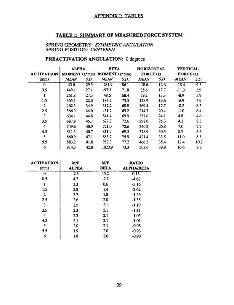
APPEND.IX I;, TABLES
TABLE 1:,, ,SUMMARY OF MEASUID FORCE SYSTEM
SPRING GEOMETRY: SYMMETRICANGULATIONSPRING POSITION: CENTERED
PREACTIVATION ANGULATION: 0 degrees
ACTIVATION(mm)00.511.522.533.5
4.5
5.5
ALPHA BETAMOMENT (g*mm) MOMENT (g*mm)MEAN43.6149.1261.8365.1462.3566.9634.1687.8749.6811.3860.9883.2914.3
HORIZONTALFORCE (g)
VERTICALFORCE (g)
S.D. MEAN S.D. MEAN S.D MEAN S.D.29.5 -281.9’" 86.1 --18.6 12.6 18.4 9.327.1 -97.3 71.8 35.6 12.7 -11.3 5.927.3 48.6 68.4 79.2 13.3 -8.9 5.922.0 183.7 73.3 128.9 19.6 -6.9 5.934.9 312.2 68.8 169.4 17.7 -0.2 8.344.0 431.2 69.2 214.7 20.4 -1.0 6.444.8 541.4 69.9 257.6 24.1 4.8 4.645.7 627.3 72.6 298.0 25.3 4.2 8.340.9 721.0 72.6 "340.2 26.8 7.0 7.740.7 811.9 69.5 378.9 30.5 8.7 6.547.1 883.7 75.9 421.4 33.5 11.0 8.541.8 952.3 77.2 466.2 35.4 12.4 10.242.8 1020.9 73.3 503.6 39.8 16.6 8.8
ACTIVATION(mm)
0.51
1.522.533.544.555.56
M/F
ALPHA-2.34.23.32.82.72.62.52.32.22.12.01.91.8
M/F RATIOBETA ALPHA/BETA
15.2 0.15-2.7 -4.620.6 -5.161.4 -2.621.8 -1.562.0 -1.352.1 -1.192.1 -1.112.1 -1.052.1 -1.012.1 -0.982.0 -0.932.0 -0.90
39
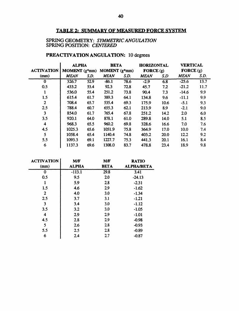
TABLE 2: SUMMARY OF MEASURED FORCE SYS,TEM
SPRING GEOMETRY: SYMMETRICANGULATIONSPRING POSITION: CENTERED
PREACTIVATION ANGULATION: 10 degrees
ACTIVATION(mm)O
0.51
1.52
2.533.544.55
5.56
ALPHAMOMENT (g*mm)
BETAMOMENT (g*mm)
HORIZONTALFORCE (g)
MEAN $.D. MEAN S.D. MEAN326.7 "52.9 -86’i 78.6 -2.9433.2 53.4 92.3 72.8 45.7536.0 55.4 251.2 73.8 90.4615.4 61.7 389.3 64.1 134.8708.4 65.7 535.4 69.3 175.9788.4 60.7 655.3 62.1 213.9854.0 61.7 765.4 67.8 251.2920.1 64.0 878.1 61.0 289.8968.3 65.5 960.2 69.8 328.61025.3 65.6 1051.9 75.8 364.91058.4 65.4 1140.4 74.8 403.21093.3 69.1 1227.7 75.3 .441.31137.3 69.6 1308.0 83.7 478.8
S.D6.’87.27.39.610.68.914.214.016.617.020.020.123.4
VERTICALFORCE (g)MEAN
-21.2-14.6-11.1-5.1-2.12.05.17.010.012.216.118.9
13.711.79.99.99.39.06.08.57.67.49.28.49.8
ACTIVATION(ram)0
0.51
1.522.53
3.54
4.55
5.56
M/F M/F RATIOALPHA BETA ALPHA]BETA
"-113.1 ’29.8 3.4i’9.5 2.0 -24.135.9 2.8 -2.314.6 2.9 -1.624.0 3.0 -1.343.7 3.1 -1.213.4 3.0 -1.123.2 3.0 -1.052.9 2.9 -1.012.8 2.9 -0.982.6 2.8 -0.932.5 2.8 -0.892.4 2.7 -0.87

41
TABLE 3: SUMMARY OF MEASURED FORCE SYSTEM
SPRING GEOMETRY: SYMMETRICANGULATIONSPRING POSITION: CENTERED
PREACTIVATION ANGULATION: 20 degrees
ACTIVATION(mm)
ALPHA BETAMOMENT (g*mm) MOMENT (g*mm)MEAN S.D. MEAN S.D.369.7 54.5 "7.4 37.4540.9 65.3 664.6 52.0615.7 61.7 780.9 54.5684.9 65.3 898.9 55.5746.1 65.3 995.8 57.9797.7 66.7 1092.3 59.6847.0 64.7 1184.3 51.9887.2 70.0 1267.9 63.2935.4 68.2 1352.2 61.3968.9 70.0 1424.8 62.2989.1 72.3 1492.0 59.51008.0 78.1 1556.9 73.71029.3 $1.9 1628.4 72.6
HORIZONTAL VERTICALFORCE (g) FORCE (g)
MEAN S.D MEAN S.D.8.8 5.8 5.0 2.682.8 17.2 14.7 3.2120.8 13.2 19.2 3.3154.8 11.8 22.7 3.3188.7 12.5 25.6 3.8224.8 26.5 29.2 4.2251.2 13.4 32.7 4.5284.6 16.6 35.4 4.0316.4 12.7 37.7 4.5347.9 14.8 40.2 5.0379.3 16.1 42.4 5.1412.4 15.1 44.9 5.2443.0 17.5 47.6 5.5
ACTIVATION(ram)0
M/F M/F
ALPHA BETA42.1 43.i6.5 8.05.1 6.54.4 5.84.0 5.33.5 4.93.4 4.73.1 4.53.0 4.32.8 4.12.6 3.92.4 3.82.3 3.7
RATIOALPHA/BETA
-0.98-0.82-0.79-0.76-0.75-0.73-0.72-0.70-0.69-0.68066-0.65-0.63

TABLE 4: SUMMARY OF MEASURED FORCE SYSTEM
SPRING GEOMETRY: SYMMETRICANGULATIONSPRING POSITION: CENTED
PREACTIVATION ANGULATION: 30 degrees
ACTIVATION(mm)00.51
1.522.533.544.555.56
ALPHA BETAMOMENT (g*mm) MOMENT (g*mm)
HORIZONTALFORCE (g)
MEAN S.D. MEAN S.D. MEAN S.D453.’ 202.8 664.2 121.8 4.3 "6.3671.2 200.7 914.9 96.7 80.8 12.2761.7 190.6 1007.7 89.9 110.1 12.6847.3 184.1 1107.1 84.6 139.0 15.0922.6 190.1 1190.3 77.6 167.2 12.61005.4 184.2 1265.2 74.7 195.7 14.81064.1 169.9 1339.2 70.2 223.9 13.71124.1 166.7 1423.7 68.8 254.1 16.41173.6 174.2 1485.8 61.6 283.4 17.61234.3 170.7 1551.0 56.0 312.0 18.61278.0 175.7 1610.6 61.5 339.1 18.41320.2 165.6 1674.0 57.5 .370.0 20.91347.6 166.8 1725.8 55.0 399.0 21.8
VERTICALFORCE (g)
MEAN"1.120.722.223.724.925.927.629.030.331.732.834.335.4
19.715.514.414.412.211.410.19.58.68.57.77.67.3
ACTIVATION(ram)00.511.522.533.544.555.56
M/F M/F RATIOALPHA BETA ALPHA/BETA
104.6 153.3 -0.738.3 11.3 -0.756.9 9.2 -0.776.1 8.0 -0.785.5 7.1 -0.785.1 6.5 -0.804.8 6.0 -0.804.4 5.6 -0.794.1 5.2 -0.794.0 5.0 -0.803.8 4.7 -0.793.6 4.5 -0.793.4 4.3 -0.78

TABLE 5: SUMMARY OF MEASURED FORCE SYSTEM
SPRING GEOMETRY: SYMMETRICANGULATIONSPRING POSITION: CENTERED
PREACTIVATION ANGULATION: 40 degrees
ACTIVATION(mm)00.51
1.522.533.544.555.56
ALPHA BETAMOMENT (g*mm) MOMENT (g*mm)
HORIZONTALFORCE (g)
VERTICALFORCE (g)
MEAN S.D. MEAN S.D. MEAN S.D MEAN S.D.820.0 119.5 591.0 89.4 -1.6 19.2 -7.7 17.4899.9 122.6 744.4 68.0 46.9 10.6 -3.0 15.5982.7 122.0 869.2 64.1 75.1 13.8 3.0 14.31056.3 119.8 996.8 52.8 110.0 11.9 3.3 14.31125.9 122.4 1110.0 50.5 141.4 13.6 4.9 14.21205.8 131.3 1232.3 46.1 171.3 13.5 8.0 13.41265.1 132.3 1338.8 42.1 206.9 16.6 10.8 14.91326.8 133.3 1428.7 39.4 236.1 17.4 12.3 13.41365.6 128.8 1526.7 42.7 264.7 17.3 18.3 15.21411.2 134.3 1608.8 37.2 296.3 17.2 20.6 13.41461.6 119.9 1701.7 33.8 330.9 19.2 18.9 13.41504.9 124.8 1768.9 33.7 357.6 19.5 23.3 14.01539.0 127.3 1848.0 31.0 388.6 23.6 22.3 13.6
ACTIVATION(mm)00.51
1.522.53
3.544.55
5.56
M/F M/F RATIOALPHA BETA ALPHA/BETA
-527.1 -379.9 -1.4419.2 15.9 -1.2313.1 11.6 -1.149.6 9.1 -1.068.0 7.8 -1.027.0 7.2 -0.986.1 6.5 -0.955.6 6.1 -0.935.2 5.8 -0.904.8 5.4 -0.884.4 5.1 -0.864.2 4.9 -0.854.0 4.8 -0.83
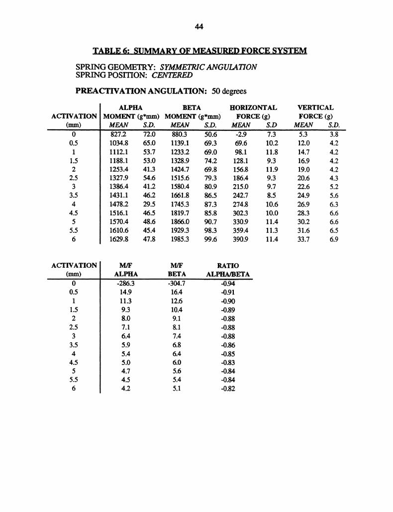
TABLE 6: SUMMARY OF MEASURED FORCE SYSTEMSPRING GEOMETRY: SYMMETRICANGULATIONSPRING POSITION: CENTRED
PREACTIVATION ANGULATION: 50 degrees
ACTIVATION(mm)00.51
1.522.533.544.555.56
ALPHA BETA HORIZONTALMOMENT (g*mm) MOMFJqT (g*mm) FORCE (g)Me. S.O. S.O. S.O827’.2 72.0 ’880.3 50.6 -2.9 7.3 5.31034.8 65.0 1139.1 69.3 69.6 10.2 12.01112.1 53.7 1233.2 69.0 98.1 11.8 14.71188.1 53.0 1328.9 74.2 128.1 9.3 16.91253.4 41.3 1424.7 69.8 156.8 11.9 19.01327.9 54.6 1515.6 79.3 186.4 9.3 20.61386.4 41.2 1580.4 80.9 215.0 9.7 22.61431.1 46.2 1661.8 86.5 242.7 8.5 24.91478.2 29.5 1745.3 87.3 274.8 10.6 26.91516.1 46.5 1819.7 85.8 302.3 10.0 28.31570.4 48.6 1866.0 90.7 330.9 11.4 30.21610.6 45.4 1929.3 98.3 .359.4 11.3 31.61629.8 47.8 1985.3 99.6 390.9 11.4 33.7
VERTICALFORCE (g)
S.D.3.84.24.24.24.24.35.25.66.36.66.66.56.9
ACTIVATION(ram)O0.51
1.522.533.544.555.56
ALPHA BETA-286.3 -304.714.9 16.411.3 12.69.3 10.48.0 9.17.1 8.16.4 7.45.9 6.85.4 6.45.0 6.04.7 5.64.5 5.44.2 5.1
RATIOALPHA/BETA
-0.91
-0.89-0.88-0.88..0.88-0.86-0.85-0.83
-0.82

45
TABLE 7: SUMMARY OF MEASURED FORCE,SYSTEM
SPREG GEOMETRY: SYMMETRICANGULATIONSPRING POSITION: CENTERED
PREACTIVATION ANGULATION: 60 degrees
ACTIVATION(mm)00.51
1.522.533.544.555.56
ALPHAMOMENT (g*mm)
BETAMOMENT (g*mm)
HORIZONTALFORCE (g)
MEAN S.D. MEAN S.D. MEAN S.D1073.2 37.0 1023.3 83.7 8.6 10.91156.9 37.6 1156.2 82.9 45.3 6.91238.7 37.7 1272.4 85.3 80.2 10.21308.2 36.2 1379.0 81.0 112.9 7.51381.3 36.3 1488.9 82.2 145.4 7.81448.0 27.8 1582.4 90.9 175.4 8.61515.8 32.6 1687.4 88.4 207.1 7.91568.8 25.9 1774.0 86.1 238.6 9.51606.6 24.4 1858.4 89.1 271.2 10.61657.4 27.3 1939.7 93.3 300.3 10.91693.1 26.6 2011.1 89.8 333.0 8.71729.1 26.8 2080.1 91.7 .362.6 9.61758.8 32.3 2151.7 91.4 393.2 10.8
VERTICALFORCE (g)
MEAN0.02.88.69.912.415.418.819.021.124.326.928.330.3
S.D.7.05.96.36.35.77.45.45.35.35.84.84.94.4
ACTIVATION(ram)00.51
1.522.533.544.55.5.56
ALPHA BETA ALPHA/BETA
125.4 119.6 -1.0625.5 25.5 -1.0115.4 15.9 -0.9811.6 12.2 -0.959.5 10.2 -0.938.3 9.0 -0.927.3 8.1 43.906.6 7.4 -0.895.9 6.9 -0.875.5 6.5 -0.865.1 6.0 -0.844.8 5.7 -0.834.5 5.5 43.82

TABLE 8: SUMMARY OF MEASURED FORCE SYSTEM
SPRING GEOMETRY: SYMMETRICANGULATIONSPRING POSITION: CENTERED
PREACTIVATION ANGULATION: 70 degrees
ACTIVATION(mm)00.51
1.522.533.544.555.56
ALPHAMO(g*mm)
BETAMOMEt
HORIZONTALrOnCE (g)
MEAN S.D. MEAN S.D. MEAN S.D1094.2’ 69.0 1313.3 81.8 -0.4 9.81293.3 73.5 1532.8 88.1 62.3 11.41368.2 71.6 1619.7 84.4 87.4 10.51438.7 71.6 1702.9 87.0 112.6 11.51512.8 69.1 1778.4 86.4 136.0 13.91577.6 72.6 1841.7 88.3 162.9 13.31652.4 66.3 1920.4 95.0 187.8 12.31715.0 75.6 1981.3 101.9 212.8 12.51768.0 65.8 2051.3 99.5 236.9 11.71809.0 58.2 2110.8 101.2 262.2 15.61850.6 61.3 2171.6 101.8 289.2 13.21893.2 62.4 2218.6 102.6 317.0 14.41929.9 60.0 2264.7 109.2 340.6 13.0
VERTICALFORCE (g)MEAN S.D.i5.8 5.419.2 4.620.6 4.121.7 4.122.9 4.024.0 3.524.9 3.626.2 4.127.2 4.128.2 4.529.6 4.330.6 4.331.8 4.5
ACTIVATION(mm)00.511.522.533.544.555.56
M/F M/F RATIOALPHA BETA ALPHA/BETA
-2462.0 -2955.6 -0.8420.7 24.6 -0.8515.6 18.5 -0.8512.8 15.1 -0.8511.1 13.1 -0.859.7 11.3 -0.868.8 10.2 -0.868.1 9.3 -0.877.5 8.7 43.866.9 8.0 -0.866.4 7.5 -0.856.0 7.0 -0.855.7 6.6 -0.85
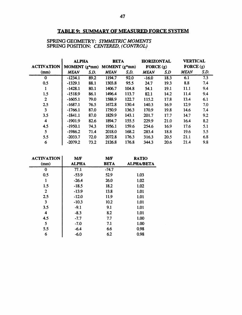
TABLE 9: SUMMARY OF MEASURED FORCE SYSTEM
SPRING GEOMETRY: SYMMETMCMOMENTSSPRING POSITION: CENTRED, (CONTROL)
ACTIVATION(ram)00.51
1.522.533.544.555.56
ALPHA BETAMOMENT (g*mm) MOMF2qr (g*mm)
HORIZONTALFORCE (g)
MEAN $.D. MEAN $.D. MEAN $.D
-1234.1 89.2 1194.7 92.0 -16.0 18.3-1329.1 88.1 1303.8 95.5 24.7 19.3-1428.1 80.1 1406.7 104.8 54.1 19.1-1518.9 $6.1 1496.4 113.7 82.1 14.2-1605.1 79.0 1588.9 122.7 115.2 17.8-1687.1 76.5 1672.8 130.4 140.3 16.9-1766.1 87.0 1750.9 136.3 170.9 19.8-1841.1 87.0 1829.9 143.1 201.7 17.7-1901.9 82.6 1894.7 155.5 229.9 21.0-1950.1 74.3 1956.1 159.6 254.6 16.9-1986.2 71.4 2018.0 168.2 283.4 18.8-2033.7 72.0 2072.8 176.3 316.3 20.5-2079.2 73.2 2126.8 176.8 344.3 20.6
VERTICALFORCE (g)
MEAN S.D.6.1 7.38.8 7.411.1 9.411.4 9.413.4 6.112.9 7.014.6 7.414.7 9.216.4 8.217.6 5.119.6 5.521.1 6.821.4 9.8
ACTIVATION(mm)00.51
1.522.533.544.555.56
M/F M/F RATIOALPHA BETA ALPHA/BETA
77.1 -74.7-53.9 52.9 1.03-26.4 26.0 1.02-18.5 18.2 1.02-13.9 13.8 1.01-12.0 11.9 1.01-10.3 10.2 1.01-9.1 9.1 1.01-8.3 8.2 1.01-7.7 7.7 1.00-7.0 7.1 1.00-6.4 6.6 0.98-6.0 6.2 0.98
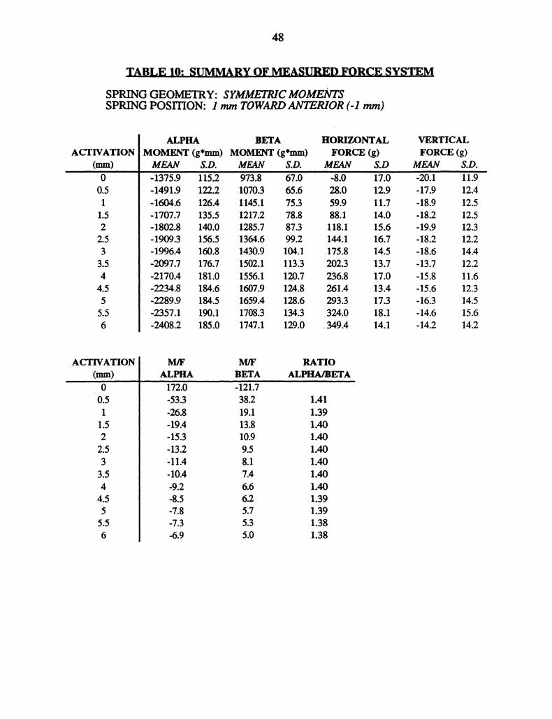
TABLE 10: SUMMARY OF MEASURED FORCE SYSTEM
SPRING GEOMETRY: SYMMETRICMOMENTSSPRING POSITION: I mm TOWARDANTERIOR (-1 ram)
ACTIVATIONCram)00.511.522.533.544.555.56
ALPHA BETA HORIZONTAL VERTICALMOMENT (g*mm) MOMENT (g*mm) FORCE (g) FORCE (g)MEAN S.D. MEAN S.D. MEAN S.D MEAN-1375.9 115.2 973.8 67.0 -8.0 17.0 -20.1-1491.9 122.2 1070.3 65.6 28.0 12.9 -17.9-1604.6 126.4 1145.1 75.3 59.9 11.7 -18.9-1707.7 135.5 1217.2 78.8 88.1 14.0 -18.2-1802.8 140.0 1285.7 87.3 118.1 15.6 -19.9-1909.3 156.5 1364.6 99.2 144.1 16.7 -18.2-1996A 160.8 1430.9 104.1 175.8 14.5 -18.6-2097.7 176.7 1502.1 113.3 202.3 13.7 -13.7-2170A 181.0 1556.1 120.7 236.8 17.0 -15.8-2234.8 184.6 1607.9 124.8 261.4 13.4 -15.6-2289.9 184.5 1659.4 128.6 293.3 17.3 -16.3-2357.1 190.1 1708.3 134.3 324.0 18.1 -14.6-2408.2 185.0 1747.1 129.0 349.4 14.1 -14.2
S.D.11.912.412.512.512.312.214.412.211.612.314.515.614.2
ACTIVATION(mm)O0.511.522.533.544.555.56
M/F M/F
ALPHA BETA172.0 -121.7-53.3 38.2-26.8 19.1-19.4 13.8-15.3 10.9-13.2 9.5-11.4 8.1-10.4 7.4-9.2 6.6-8.5 6.2-7.8 5.7-7.3 5.3-6.9 5.0
RATIOALPHA/BETA
IAI1.391.401.401.401.401.401.401.391.391.381.38
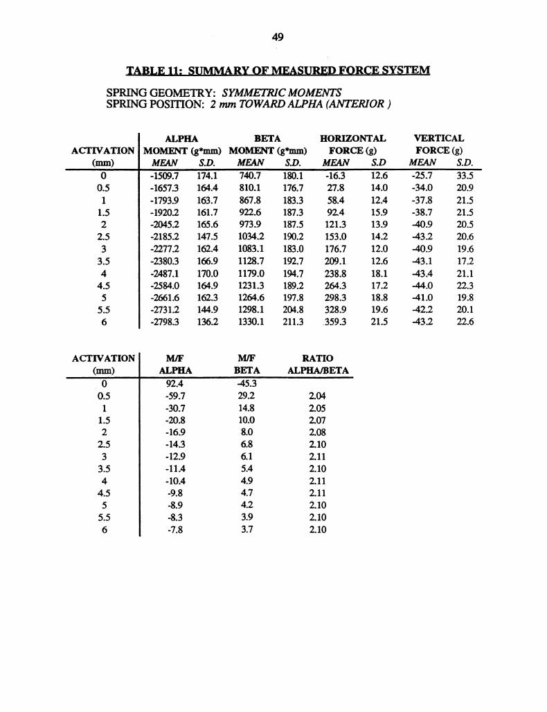
TABLE 11: SUMMARY OF MEASURED FORCE SYSTEM
SPRING GEOMETRY: SYMMETRICMOMENTSSPRING POSITION: 2 mm TOWARDALPHA (ANTEIOR )
ACTIVATION(mm)00.511.522.533.544.555.56
ALPHA BETA HORIZONTALMOMENT (g*mm) MOMENT (g*mm) FORCE (g)MEAN S.D. MEAN S.D. MEAN S.D-1509.7 174.1 740.7 180.1 -16.3 12.6-1657.3 164.4 810.1 176.7 27.8 14.0-1793.9 163.7 867.8 183.3 58.4 12.4-1920.2 161.7 922.6 187.3 92.4 15.9-2045.2 165.6 973.9 187.5 121.3 13.9-2185.2 147.5 1034.2 190.2 153.0 14.2-2277.2 162.4 1083.1 183.0 176.7 12.0-2380.3 166.9 1128.7 192.7 209.1 12.6-2A87.1 170.0 1179.0 194.7 238.8 18.1-2584.0 164.9 1231.3 189.2 264.3 17.2-2661.6 162.3 1264.6 197.8 298.3 18.8-2731.2 144.9 1298.1 204.8 328.9 19.6-2798.3 136.2 1330.1 211.3 .359.3 21.5
VERTICALFORCE (g)MEAN-5.7-34.0-37.8-38.7-40.9-43.2-40.9-4.3.1-43.4-44.0-41.0-42.2-43.2
S.D.33.520.921.521.520.520.619.617.221.122.319.820.122.6
ACTIVATION(mm)00.51
1.52
2.53
3.544.55
5.56
M/F M/F RATIOALPHA BETA ALPHA/BETA
92.4 -45.3-59.7 29.2 2.04-30.7 14.8 2.05-20.8 10.0 2.07-16.9 8.0 2.08-14.3 6.8 2.10-12.9 6.1 2.11-llA 5.4 2.10-10A 4.9 2.11-9.8 4.7 2.11-8.9 4.2 2.10-8.3 3.9 2.10-7.8 3.7 2.10
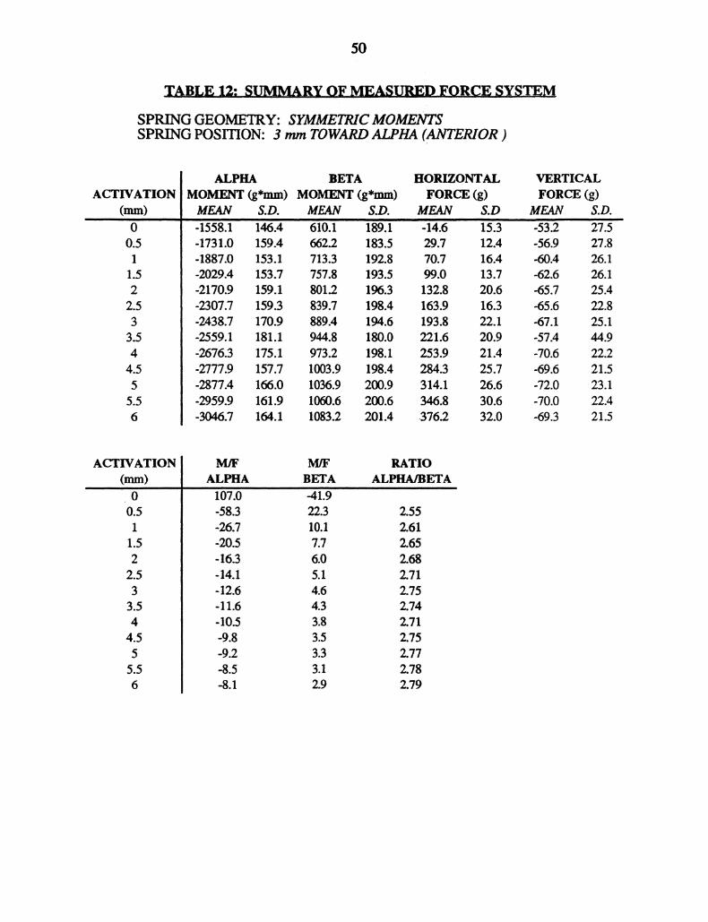
50
TABLE 12: SUMMARY OF MIASUREDFORCE SYSTEM
SPRING GEOMETRY: SYMMETRICMOMENTSSPRING POSITION: 3 mm TOWARD ALPHA (ANTERIOR)
ACTIVATION(mm)00.511.522.533.544.555.56
ALPHA BETAMOMENT (g*mm) MOMENT (g*mm)
HORIZONTALFORCE (g)
VERTICALFORCE (g)
MEAN S.D. MEAN S.D. MEAN S.D MEAN S.D.-1558.1 1,6.4 610.1 189.1 -14.6 "15.3 -53.2 27.5-1731.0 159.4 662.2 183.5 29.7 12.4 -56.9 27.8-1887.0 153.1 713.3 192.8 70.7 16.4 -60.4 26.1-2029.4 153.7 757.8 193.5 99.0 13.7 -62.6 26.1-2170.9 159.1 801.2 196.3 132.8 20.6 -65.7 25.4-2307.7 159.3 839.7 198.4 163.9 16.3 -65.6 22.8-2438.7 170.9 889.4 194.6 193.8 22.1 -67.1 25.1-2559.1 181.1 944.8 180.0 221.6 20.9 -57.4 44.9-2676.3 175.1 973.2 198.1 253.9 21.4 -70.6 22.2-2777.9 157.7 1003.9 198.4 284.3 25.7 -69.6 21.5-2877.4 166.0 1036.9 200.9 314.1 26.6 -72.0 23.1-2959.9 161.9 1060.6 200.6 346.8 30.6 -70.0 22.4-3046.7 164.1 1083.2 201.4 .376.2 32.0 -69.3 21.5
ACTIVATION(ram)00.51
1.522.533.544.555.56
M/F M/F RATIOALPHA BETA ALPHA/BETA
lb7.0’ -4i’.-58.3 22.3 2.55-26.7 10.1 2.61-20.5 7.7 2.65-16.3 6.0 2.68-14.1 5.1 2.71-12.6 4.6 2.7511.6 4.3 2.74
-10.5 3.8 2.71-9.8 3.5 2.75-9.2 3.3 2.77-8.5 3.1 2.78-8.1 2.9 2.79

51
TABLE 13: SUMMARY OF MEASURED FORCE SYSTEM
SPRING GEOMETRY: SYMMETRICMOMENTSSPRING POSITION: 4 mm TOWARDALPHA (ANTERIOR)
ACTIVATION(mm)O0.51
1.522.53
3.544.55
5.56
ALPHAMOMENT (g*mm)
BETAMOMENT (g*mm)
HORIZONTALFORCE (g)
VERTICALFORCE (g)
t s.o. ue. s.o. lea2v S.O 1 S.O.-1455.9 129.i 507.8 27.6 -9.2 15.4 -48.6 18.4-1645.3 126.3 534.2 223.9 40.7 10.9 -54.7 16.9-1819.1 122.2 562.9 218.9 73.4 10.7 -59.1 16.3-1984.1 117.4 582.7 209.0 106.7 8.0 -64.0 16.3-2139.8 120.2 609.3 198.2 140.0 11.3 -67.6 14.7-2302.6 131.1 645.2 167.8 171.3 8.6 -70.7 13.2-2451.8 129.7 675.0 174.9 201.3 10.8 -72.4 13.1-2588.6 137.6 704.1 174.6 231.1 13.7 -75.8 11.7-2716.8 130.4 711.8 181.8 263.2 12.1 -77.3 10.8-2845.2 143.8 744.2 172.7 292.3 12.3 -78.9 12.1-2956.7 139.5 762.0 177.7 322.2 13.4 -80.8 11.4-3053.9 141.2 776.8 186.2 356.2 14.2 -82.7 12.1-3150.4 123.0 788.6 196.9 .387.1 15.8 -82.2 12.4
ACTIVATION(mm)00.51
1.522.533.544.555.56
M/F M/F RATIOALPHA BETA ALPHA/BETA
157.9 -55.1-40.5 13.1 2.87-24.8 7.7 3.08-18.6 5.5 3.23-15.3 4.4 3.41-13.4 3.8 3.51-12.2 3.4 3.57-11.2 3.0 3.63-10.3 2.7 3.68-9.7 2.5 3.82-9.2 2.4 3.82-8.6 2.2 3.88-8.1 2.0 3.93

52
TABLE 14: SUMMARY OF MEASURED FORCE SYSTEM
SPRING GEOMETRY: SYMMETRICMOMENTSSPRING POSITION: 1ram TOWARD BETA (POSRIOR )
ACTIVATION(mm)00.511.522.533.5
4.555.56
ALPHA BETA HORIZONTALMOMENT (g*mm) MOMENT (g*mm) FORCE (g)MF.OI s.o. s.o. MEAN-838.0" 128.9 1409.4 :2.5 2.1 16.4-912.7 129.8 1556.1 81.6 37.1 17.1-975.4 135.9 1670.7 101.7 66.7 17.7-1041.3 136.5 1790.1 118.3 100.4 21.2-1105.7 139.8 1901.8 123.6 132.3 23.1-1169.1 145.1 2012.2 146.6 162.8 24.4-1223.7 149.8 2122.4 156.1 194.4 25.0-1289.7 163.9 2225.0 171.2 224.7 27.1-1306.4 145.2 2295.2 170.0 255.4 29.1-1342.3 140.1 2371.6 175.0 289.1 34.2-1370.8 136.3 2450.0 188.8 315.1 32.3-1389.8 135.9 2520.4 193.6 348.1 35.0-1411.7 129.4 2578.7 201.4 38.9 38.9
VERTICALFORCE (g)MEAN S.D.42.3 6.347.3 6.949.3 5.552.4 5.554.1 8.256.4 6.057.8 6.959.8 8.161.4 7.064.6 7.464.7 7.765.7 7.366.8 9.0
ACTIVATION(ram)00.511.522.533.544.555.56
M/F M/F
ALPHA BETA-396.9 667.6-24.6 41.9-14.6 25.1-10.4 17.8-8.4 14.4-7.2 12.4-6.3 10.9-5.7 9.9-5.1 9.0-4.6 8.2-4.4 7.8--4.0 7.2-3.7 6.8
RATIOALPHA/BETA
0.59O.59O.580.580.58O.580.580.550.57O.570.560.55

53
TABLE 15: SUMMARY OF MEASURED FORCE SYSTEM
SPRING GEOMETRY: SYMMETRIC MOMENTSSPRING POSITION: 2mm TOWARD BETA (POSRIOR )
ACTIVATIONmm)00.51
1.522.533.544.555.56
ALPHA BETAMOMENT (g*mm) MOMENT (g*mm)
HORIZONTALFORCE (g)
MEAN S.D. MEAN S.D. MEAN S.D-720.0 37.3 1384.9 77.2 -4.0 4.3-771.7 43.4 1557.6 82.8 32.0 10.4-819.1 62.3 1690.4 74.4 63.8 7.2-878.2 67.9 1822.3 70.4 97.2 11.4-924.6 75.4 1953.2 73.3 129.6 11.1-967.2 80.8 2079.3 86.2 157.3 11.9-1013.8 80.7 2205.2 87.6 193.0 13.1-1059.6 96.5 2308.0 99.4 222.8 16.3-1089.7 104.6 2414.3 102.4 252.6 18.61108.9 113.2 2505.4 105.6 279.4 17.9-1136.2 126.7 2598.2 121.6 313.8 22.4-1156.2 131.2 2689.4 124.8 346.4 22.8-1173.2 138.3 2772.6 133.1 376.6 26.5
VERTICALFORCE (g)
MEAN53,260.665.368.073.377.078.981.184.388.289.291.090.8
S.D.4.27.04.64.66.56.16.06.06.36.47.97.16.6
ACTIVATION(mm)00.51
1.52
2.533.544.555.56
M/F M/F
ALPHA BETA’lS0.0 -346.2-24.1 48.7-12.8 26.5-9.0 18.7-7.1 15.1-6.1 13.2-5.3 11.4-4.8 10.4-4.3 9.6-4.0 9.0-3.6 8.3-3.3 7.8-3.1 7.4
RATIOALPHA/BETA
0.520.500.480.480.470.470.460.460.450.440.440.43

54
TABLE 16: SUMMARY OF MEASURED FORCE SYSTEM
SPRING GEOMETRY: SYMMETRICMOMENTSSPRING POSITION: 3 mm TOWARD BETA (POSTERIOR)
ACTIVATION(mm)00.511.522.533.544.555.56
ALPHA BETAMOMENT (g*mm) MOMENT (g*mm)
HORIZONTALFORCE (g)
MEAN S.D. MEAN S.D. MEAN S.D4506.1 .6 1397.6 147.8 "-1.7 17.2-635.0 40.7 1564.2 144.7 33.6 19.9-678.7 44.0 1723.4 141.3 70.9 16.9-713.7 47.3 1875.0 133.6 103.1 18.0-743.6 52.8 2023.6 137.3 134.6 19.8-778.2 57.8 2167.2 147.3 171.1 19.9-812.1 57.6 2305.0 146.4 199.7 23.2-829.1 55.2 2424.9 142.2 231.7 23.3-837.6 50.6 2537.7 144.9 264.2 24.5-849.0 50.8 2653.7 155.1 293.7 27.5-857.2 51.8 2768.3 161.9 325.4 28.2-868.2 51.1 2873.3 175.4 355.8 32.0-873.2 45.7 2967.7 173.2 388.9 35.0
VERTICALFORCE (g)
MEAN59.468.173.280.085.089.193.897.8100.6105.2109.3110.7112.1
S.D.11.511.211.311.39.38.77.57.47.77.07.65.85.7
ACTIVATION(ram)00.511.522.533.544.555.56
M/F M/F RATIOALPHA BETA ALPHA/BETA
363.7 -838.5-18.9 46.6 0.43-9.6 24.3 0.41-6.9 18.2 0.39-5.5 15.0 0.38-4.5 12.7 0.37-4.1 11.5 0.36-3.6 10.5 0.35-3.2 9.6 0.34-2.9 9.0 0.33-2.6 8.5 0.32-2.4 8.1 0.31-2.2 7.6 0.30
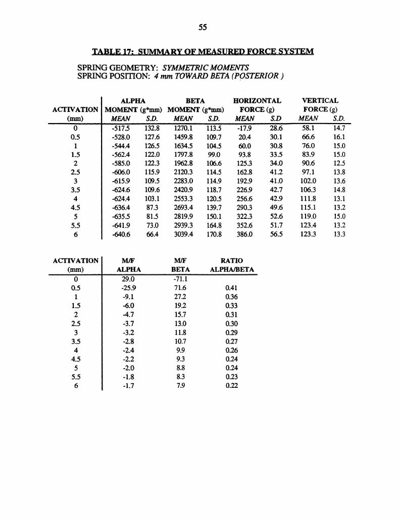
55
TABLE 17: SUMMARY OF 1VIEASURID FORCE SYSTEM
SPRING GEOMETRY: SYMMETRICMOMENTSSPRING POSION: 4 mm TOWARD BETA (POSTERIOR)
ACTIVATION(mm)00.51
1.522.533.544.555.56
ALPHA BETAMOMENT (g*mm) MOMENT (g*mm)
HORIZONTALFORCE (g)
MEAN S.D. MEAN S.D. MEAN S.D"-517.5 13}.8 1270.1 113.5 -17.9 28.6-528.0 127.6 1459.8 109.7 20.4 30.1-544.4 126.5 1634.5 104.5 60.0 30.8-562.4 122.0 1797.8 99.0 93.8 33.5-585.0 122.3 1962.8 106.6 125.3 34.0-606.0 115.9 2120.3 114.5 162.8 41.2-615.9 109.5 2283.0 114.9 192.9 41.0-624.6 109.6 2420.9 118.7 226.9 42.7-624.4 103.1 2553.3 120.5 256.6 42.9-636.4 87.3 2693.4 139.7 290.3 49.6-635.5 81.5 2819.9 150.1 322.3 52.6-641.9 73.0 2939.3 164.8 352.6 51.7-640.6 66.4 3039.4 170.8 386.0 56.5
VERTICALFORCE (g)
MEAN58.166.676.083.990.697.1102.0106.3111.8115.1119.0123.4123.3
S.D.14.716.115.015.012.513.813.614.813.113.215.013.213.3
ACTIVATION(mm)O0.51
1.522.533.544.555.56
ALPHA BETA29.0 -71.1-25.9 71.6-9.1 27.2-6.0 19.2-4.7 15.7-3.7 13.0-3.2 11.8-2.8 10.7-2.4 9.9-2.2 9.3-2.0 8.8-1.8 8.3-1.7 7.9
RATIOALPHA/BETA
0.410.360.330.310.300.290.270.260.240.240.230.22
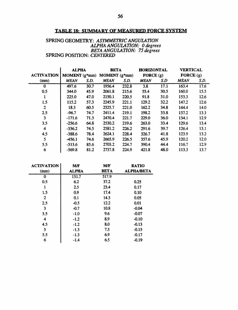
56
TABLE 18: SUMMAR,,Y OF MEASURED FORCE SYSTEM
SPRING GEOMETRY: ASYMMEIRICANGUI.ATIONALPHA ANGULATION: 0 degreesBETA ANGULATION: 75 degrees
SPRING POSITION: CENTERED
ACTIVATION(mm)00.51
1.522.533.544.555.56
ALPHAMOMENT (g*mm)
BETAMOMENT (g*mm)
HORIZONTALFORCE
MEAN S.D. MEAN $.D. MEAN47.6 30.7 i956. "232’.8" 3.8344.0 45.9 2061.8 215.6 55.4225.0 47.0 2150.1 220.5 91.8115.2 57.3 2245.9 221.1 129.218.3 60.5 2325.7 221.0 162.2-96.7 74.7 2411.4 219.1 198.2-171.6 71.3 2470.4 221.7 229.0-256.6 64.8 2530.2 219.6 263.0-336.2 74.5 2581.2 226.2 291.6-388.6 78.4 2624.1 228.4 326.7-456.1 74.6 2665.9 226.5 357.6-513.6 85.6 2703.2 224.7 390.4-569.8 81.2 2737.8 224.9 421.8
S.D
30.531.032.234.833.836.033.439.741.845.944.448.0
VERTICALFORCE (g)
MEANi63.160.0153.3147.2144.4137.2134.1129.6126.4123.9120.2116.7113.3
17.615.512.612.614.013.312.913.413.113.212.012.913.7
ACTIVATION(ram)00.51
1.522.533.544.555.56
M/F M/F RATIOALPHA BETA ALPHA/BETA
131.7 517’962 37.2 0.252.5 23.4 0.170.9 17.4 0.100.1 14.3 0.05-0.5 12.2 0.01-0.7 10.8 -0.04-1.0 9.6 -0.07-1.2 8.9 -0.10-1.2 8.0 -0.13-1.3 7.5 -0.151.3 6.9 -0.17
-1.4 6.5 -0.19

57
TABLE 19: SUMMARY OF MEASURED FORCE SYSTEM
SPRINGGEOMETRY: ASYMMETRICANGULATIONALPHA ANGULATION: 15 degreesBETA ANGULATION: 75 degrees
SPRING POSITION: CENTERED
ACTIVATION(mm)
0.51
1.522.533.544.555.56
ALPHA BETAMOMErff (g*mm) MOMENT (g*mm)MEAN S.D. MEAN S.D.233.7 i’46.4114.3 148.7-1.1 145.2-96.9 140.8-196.2 144.3-291.2 153.1-383.0 159.9-469.7 159.8-531.3 154.2-579.2 136.0-637.3 119.3-684.3 123.9-7332 114.6
HORIZONTALFORCE (g)
VERTICALFORCE (g)
MEAN S.D MEAN S.D.1819.8’ 120.9 0:4 13.6 135.0 7.’1942.7 114.9 29.9 17.1 131.7 9.22047.4 100.6 64.2 21.3 127.4 8.62149.9 101.6 98.8 20.2 125.2 8.62248.9 102.7 130.1 25.1 121.1 7.62340.7 95.6 161.6 24.9 118.1 7.72437.7 98.8 193.9 26.2 116.1 7.52514.9 99.3 224.9 23.7 112.7 9.62578.2 96.4 254.1 24.8 108.6 9.42624.7 100.1 284.8 25.8 107.9 10.32680.9 104.6 316.9 27.5 105.9 8.82726.8 105.5 347.4 26.5 101.2 10.92767.3 104.1 378.4 29.1 99.8 9.7
ACTIVATION(ram)00.51
1.522.53
3.544.555.56
M/F M/F
ALPHA BETA525.7 409t.53.8 65.00.0 31.9-1.0 21.8-1.5 17.3-1.8 14.5-2.0 12.6-2.1 11.2-2.1 10.1-2.0 9.2-2.0 8.5-2.0 7.8-1.9 7.3
RATIOALPHA/BETA
0.130.060.00-0.05
-0.12-0.16-0.19-0.21-0.22-0.24-0.25

58
TABLE 20: SUMMARY OF MEASI.ED FORCE SYSTEM
SPRING GEOMETRY: ASYMMETRICANGULATIONALPHA ANGULATION: 30 degreesBETA ANGULATION: 75 degrees
SPRING POSITION: CENTERED
ACTIVATIONmm)O0.511.522.533.544.555.56
ALPHA BETA IIORIZONTALMOMENT (g*mm) MOMENT (g*mm) FORCE (g)MEAN S.D. MEAN S.D. MEAN S.D
i708.8 165.4 ’-8.8 10.41822.9 148.0 28.1 11.71921.9 143.4 61.7 13.92014.9 137.5 91.1 14.52108.1 134.8 123.4 14.42190.3 127.8 158.0 13.42269.9 116.2 187.2 15.92357.8 111.1 218.9 15.02424.6 115.9 246.7 15.22462.9 119.0 279.9 15.92508.7 122.1 310.4 15.12551.8 128.5 340.2 17.52599.0 125.3 371.8 18.6
-159.8 115.7-281.7 121.7-385.1 118.3-484.2 119.8-575.0 119.8-671.1 126.0-765.1 132.1-860.3 146.5-937.3 133.0-995.1 118.5-1049.3 108.5-1093.9 97.6-1153.7 92.6
VERTICALFORCE (g)
MEAN103.0100.999.195.392.788.387.785.284.482.281.179.179.0
S.D.13.011.210.410.411.914.012.612.212.713.012.111.811.7
ACTIVATION(ram)00.51
1.522.533.544.555.56
M]F M/F RATIOALPHA BETA ALPHA/BETA
’18.2 -194.7-10.0 64.8 -0.09-6.2 31.2 -0.15-5.3 22.1 -0.20-4.7 17.1 -02A-4.2 13.9 -0.27-4.1 12.1 -0.31-3.9 10.8 -0.34-3.8 9.8 -0.36-3.6 8.8 -0.39-3.4 8.1 -0.40-3.2 7.5 -0.42-3.1 7.0 -0.43
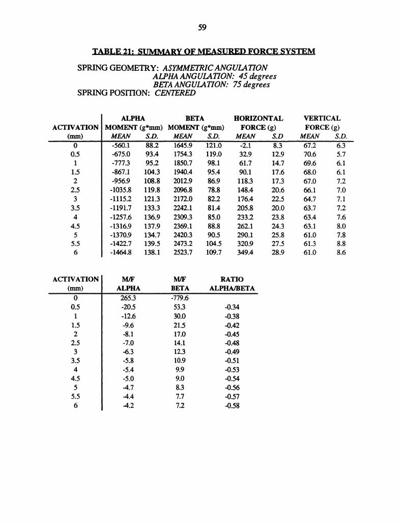
59
TABLE 21: SUMMARY OF MEASURED FORCE SYSTEM
SPRING GEOMETRY: ASYMMETRICANGULATIONALPHA ANGULATION: 45 degreesBETA ANGULA770N: 75 degrees
SPRING POSITION: CENTERED
ACTIVATION(mm)00.51
1.522.53
3.544.55
5.56
ALPHA BETAMOMENT (g*mm) MOMENT (g*mm)
HORIZONTALFORCE (g)
MEAN S.D. MEAN S.D. MEAN S.D-5601 88.2 164:.9’" J21.0 -2.1 8.3-675.0 93.4 1754.3 119.0 32.9 12.9-777.3 95.2 1850.7 98.1 61.7 14.7-867.1 104.3 1940.4 95.4 90.1 17.6-956.9 108.8 2012.9 86.9 118.3 17.3-1035.8 119.8 2096.8 78.8 148.4 20.6-1115.2 121.3 2172.0 82.2 176.4 22.5-1191.7 133.3 2242.1 81.4 205.8 20.0-1257.6 136.9 2309.3 85.0 233.2 23.8-1316.9 137.9 2369.1 88.8 262.1 24.3-1370.9 134.7 2420.3 90.5 .290.1 25.8-1422.7 139.5 2473.2 104.5 320.9 27.5-1464.8 138.1 2523.7 109.7 349.4 28.9
VERTICALFORCE (g)
MEAN67.270.669.668.067.066.164.763.763.463.161.061.361.0
5.76.16.17.27.07.17.27.68.07.88.88.6
ACTIVATION(mm)00.51
1.522.533.544.555.56
M/F M/F RATIOALPHA BETA ALPHA/BETA
265.3 -779.6-20.5 53.3 -0.34-12.6 30.0 -0.38-9.6 21.5 43.42-8.1 17.0 43.45-7.0 14.1 43.4845.3 12.3 -0.49-5.8 10.9 -0.51-5.4 9.9 -0.53-5.0 9.0 -0.54-4.7 8.3 43.56-4.4 7.7 -0.57-4.2 7.2 -0.58
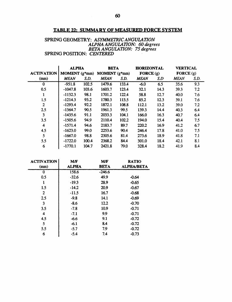
TABLE,, 22: SUMMA.RY OF MEASURED FORCE SYSTEM
SPRING GEOMETRY: ASYMMETRICANGULATIONALPHA ANGULATION: 60 degreesBETA ANGULATION: 75 degrees
SPRING POSITION: CENTERED
ACTIVATION(ram)O0.511.522.533.544.555.56
ALPHA BETAMOMENT (g*mm) MOMENT (g*mm)
HORIZONTALFORCE ()
MEAN $.D. MEAN S.D. MEAN S.D-951.8 102.5 1479.6 133.4 -6.0 6."’-1047.8 103.6 1603.7 123.4 32.1 14.3-1132.3 98.1 1701.2 122.4 58.8 12.7-1214.3 93.2 1780.3 113.5 85.2 12.31293.4 92.2 1872.1 108.8 112.1 13.2-1364.7 90.5 1961.3 99.5 139.3 14.4-1435.6 91.1 2033.3 104.1 166.0 16.31505.6 94.9 2110.4 102.2 194.0 15.4-1571.4 94.6 2183.7 89.7 220.2 16.9-1623.0 99.0 2253.6 90.4 246.4 17.8-1667.0 98.8 2305.6 81.4 273.6 18.9-1722.0 100.4 2368.2 84.4 301.0 18.4-1770.1 104.7 2421.8 79.0 328.4 18.2
VERTICALFORCE (g)
MEAN5.639.340.039.139.040.340.740.441.241.041.842.141.9
S.D.9.37.27.67.67.26.46.47.56.77.57.18.18.4
ACTIVATION(nun)O0.51
1.522.533.544.55
5.56
M/F M/F RATIOALPHA BETA ALPHA/BETA
158.6 -24616-32.6 49.9 -0.64-19.3 28.9 -0.65-14.2 20.9 4).6711.5 16.7 -0.68-9.8 14.1 -0.69-8.6 12.2 -0.70-7.8 10.9 -0.71-7.1 9.9 -0.71-6.6 9.1 -0.72-6.1 $.4 -0.72-5.7 7.9 43.72-5.4 7.4 -0.73

61
TABLE ,3: SUMMARYOF MEASURED FORCE SYSTEM
SPRING GEOMETRY: ASYMMETRICANGUL4TIONALPHAANGUL4TION: 75 degreesBETA ANGULATION: 0 degrees
SPRING POSITION: CENTERED
ACTIVATION(mm)0
0.51
1.522.533.544.55
6
ALPHAMOMENT (g*mm)
BETAMOMENT (g*mm)
HORIZONTALFORCE (g)
MEAN S.D. MEAN S.D. MEAN S.D-23060 188.4 -1228.2 79.2 -26,6" 7.8-2365.4 170.3 -1014.7 56.7 32.9 14.9-2447.9 164.4 -886.4 60.1 64.6 12.6-2523.8 167.8 -762.6 52.3 98.2 13.0-2596.6 170.3 -640.9 57.2 130.2 14.3-2641.6 168.1 -522.6 52.4 160.4 8.1-2703.7 181.1 -405.7 59.5 196.4 14.7-2743.0 187.6 -290.7 56.5 227.0 10.7-2797.1 207.4 -181.8 58.6 262.0 10.1-2843.9 243.0 -90.6 52.8 293.8 16.1-281.8.7 183.7 32.0 71.8 330.0 13.8-2820.7 178.9 107.4 57.6 365.2 17.2-2824.6 173.9 191.8 60.9 402.4 20.0
VERTICALFORCE (g)MEAN-208.2-186.9-181.1-170.1-161.1-163.9-145.0-136.7-129.2-123.1-114.0-107.2-99.6
20.113.515.015.014.331.912.611.69.89.910.78.67.4
ACTIVATION(ram)O0.51
1.522.533.544.555.56
M/F M/F RATIOALPHA BETA ALPHA/BETA
86.8 46.3 0.54-71.9 -30.9 0.43-37.9 -13.7 0.36-25.7 -7.8 0.30-19.9 -4.9 0.25-16.5 -3.3 0.20-13.8 -2.1 0.15-12.1 -1.3 0.11-10.7 -0.7 0.07-9.7 -0.3 0.03-8.5 0.1 4).01
-7.7 0.3 -0.04-7.0 0.5 -0.07
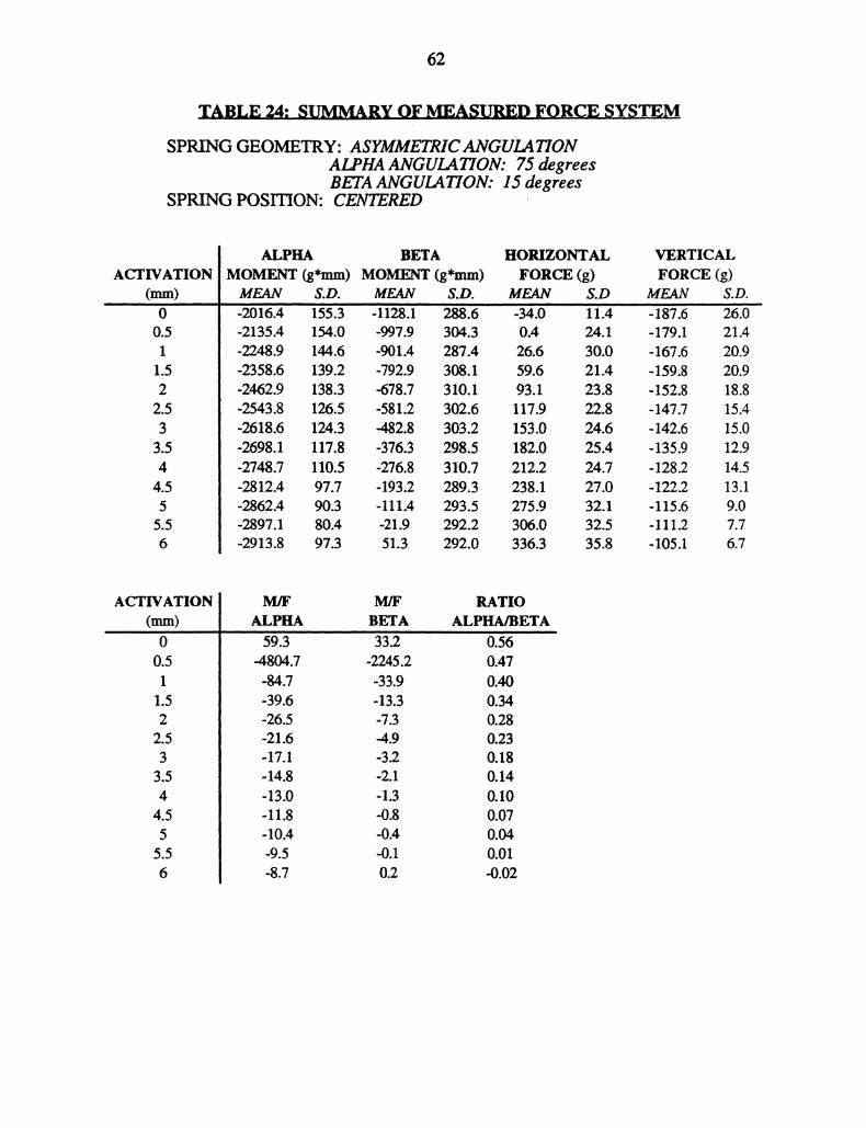
62
TABLE 24: SUMMARY OF MEASURED FORCE SYSTEM
SPRING GEOMETRY: ASYMMETRICANGULATIONALPHA ANGULATION: 75 degreesBETA ANGULATION: 15 degrees
SPRING POSITION: CENTERED
ACTIVATION(mm)00.51
1.522.533.544.555.56
ALPHAMOMENT (g*mm)
BETAMOMENT (g*mm)
HORIZONTALFORCE (g)
MEAN S.D. MEAN S.D. MEAN S.D-2016.4’ 155’.3 -1128.1 288.6 -34.0-2135.4 154.0 -997.9 304.3 0.4 24.1-2248.9 144.6 -901.4 287.4 26.6 30.0-2358.6 139.2 -792.9 308.1 59.6 21.4-2462.9 138.3 -678.7 310.1 93.1 23.8-2543.8 126.5 -581.2 302.6 117.9 22.8-2618.6 124.3 -482.8 303.2 153.0 24.6-2698.1 117.8 -376.3 298.5 182.0 25.4-2748.7 110.5 -276.8 310.7 212.2 24.7-2812.4 97.7 -193.2 289.3 238.1 27.0-2862.4 90.3 -111.4 293.5 275.9 32.1-2897.1 $0.4 -21.9 292.2 306.0 32.5-2913.8 97.3 51.3 292.0 336.3 35.8
VERTICALFORCE (g)
MEAN S.D.-187.6 26.0-179.1 21.4-167.6 20.9-159.8 20.9-152.8 18.8-147.7 15.4-142.6 15.0-135.9 12.9-128.2 14.5-122.2 13.1-115.6 9.0-111.2 7.7-105.1 6.7
ACTIVATION(mm)0
0.51
1.52
2.533.544.55
5.56
M/F M/F RATIOALPHA BETA ALPHA/BETA
59.3 33.2 0.56-4804.7 -2245.2 0.47-84.7 -33.9 0.40-39.6 -13.3 0.34-26.5 -7.3 0.28-21.6 -4.9 0.23-17.1 -3.2 0.18-14.8 -2.1 0.14-13.0 -1.3 0.10-11.8 -0.8 0.07-10.4 -0.4 0.04-9.5 -0.1 0.01-8.7 0.2 -0.02
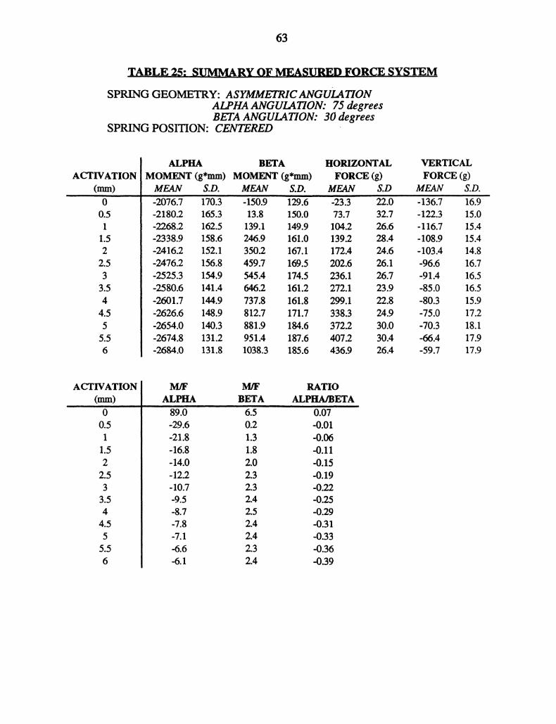
63
TABLE 25: SUMMARY OF MEASUREDFORCE SYSTEM
SPRING GEOMETRY: ASYMMETRICANGULATIONALPHA ANGULATION: 75 degreesBETA ANGULATION: 30 degrees
SPRING POSITION: CENTERED
ACTIVATION(mm)00.51
1.522.533.544.555.56
ALPHAMOMENT (g*mm)
BETAMOMENT (g*mm)
HORIZONTALFORCE (g)
MEAN S.D. MEAN S.D. MEAN S.D-2076.7 170.3 -150.9 129.6 -23.3 22.0-2180.2 165.3 13.8 150.0 73.7 32.7-2268.2 162.5 139.1 149.9 104.2 26.6-2338.9 158.6 246.9 161.0 139.2 28.4-2416.2 152.1 350.2 167.1 172.4 24.6-2476.2 156.8 459.7 169.5 202.6 26.1-2525.3 154.9 545.4 174.5 236.1 26.7-2580.6 141.4 646.2 161.2 272.1 23.9-2601.7 144.9 737.8 161.8 299.1 22.8-2626.6 148.9 812.7 171.7 338.3 24.9-2654.0 140.3 881.9 184.6 372.2 30.0-2674.8 131.2 951.4 187.6 407.2 30.4-2684.0 131.8 1038.3 185.6 436.9 26.4
VERTICALFORCE (g)
MEAN136.-122.3-116.7-108.9-103.4-96.6-91.4-85.0-80.3-75.0-70.3--66.4-59.7
16.915.015.415.414.816.716.516.515.917.218.117.917.9
ACTIVATION(mm)00.511.522.533.544.555.56
M]F M/F RATIOALPHA BETA ALPHA/BETA
89.0 6.5 0.07-29.6 0.2 -0.01-21.8 1.3 -0.06-16.8 1.8 -0.11-14.0 2.0 -0.15-12.2 2.3 -0.19-10.7 2.3 -0.22-9.5 2.4 -0.25-8.7 2.5 -0.29-7.8 2.4 -0.31-7.1 2.4 -0.33-6.6 2.3 -0.36-6.1 2.4 -0.39
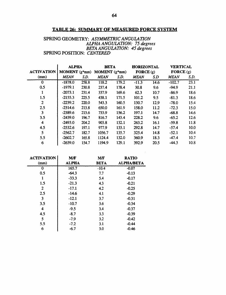
TABLE26: SUMMARYOF MEASURED_FORCE SYSTEM
SPRING GEOMETRY: ASYMMETRICANGULATIONALPHA ANGULATION: 75 degreesBETA ANGULATION: 45 degrees
SPRING POSITION: CENTERED
ACTIVATION(mm)00.51
1.522.533.544.555.56
ALPHA BETAMOMENT (g*mm) MOMENT (g*mm)
HORIZONTALFORCE (g)
MEAN S.D. MEAN S.D. MEAN-1878,0 258’.8 i18.2 ’179.2’ -11.3-1979.1 230.8 237.4 178.4 30.8-2073.1 231.4 337.9 169.6 62.3-2155.3 225.5 438.1 171.5 101.2-2239.2 220.0 543.3 160.5 130.7-2314.6 213.8 650.0 161.9 158.0-2389.6 213.6 733.9 156.2 197.1-2439.0 196.7 816.7 143.4 228.2-2493.0 204.2 903.8 132.1 263.2-2532.6 197.1 977.9 133.1 292.8-2562.7 182.7 1056.7 135.7 .325.4-2602.7 165.8 1124.4 132.0 360.9-2639.0 154.7 1194.9 129.1 392.9
S.D14.69.610.79.512.911.214.79.616.114.714.818.320.5
VERTICALFORCE (g)
MEAN-102.7-94.9-86.9-81.3-78.0-72.3-68.8-65.2-59.8-57.4-52.1-47.4..44.3
23.’i"21.118.618.615.415.014.612.611.810.010.410.710.8
ACTIVATION(mm)00.51
1.522.533.544.555.56
M/F M/F RATIOALPHA BETA ALPHA/BETA
’1i5.7 -10.4 -0.07-64.3 7.7 .-0.13-33.3 5.4 .-0.17-21.3 4.3 -0.2117.1 4.2 -0.2514.6 4.1 -0.29-12.1 3.7 -0.31-10.7 3.6 -0.34-9.5 3.4 -0.37-8.7 3.3 -0.39-7.9 3.2 -0.42-7.2 3.1 -0.44-6.7 3.0 -0.46
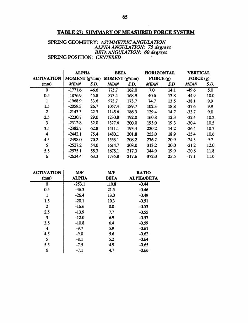
65
TABLE.27: SUMMARY OF MEASURED FORCE SYSTEMSPRING GEOMETRY: ASYMMETRICANGULATION
ALPHA ANGULATION: 75 degreesBETA ANGULATION: 60 degrees
SPRING POSITION: CENTERED
ACTIVATION(mm)00.51
1.522.53
3.544.555.56
ALPHAMOMENT (g*mm)
BETAMOMENT (g*mm)
HORIZONTALFORCE (g)
VERTICALFORCE (g)
MEAN S.D. MEAN S.D. MEAN S.D MEAN S.D.-1771.6 46.6 775. 162.0" 7.6 1411 -49.6 5.0-1876.9 45.8 873.4 168.9 40.6 13.8 -44.9 10.0-1968.9 33.6 973.7 173.7 74.7 13.5 -38.1 9.9-2059.3 26.7 1057.4 189.7 102.3 18.8 -37.6 9.9-2143.3 22.3 1145.6 186.3 129.4 14.7 -33.7 9.0-2230.7 29.0 1230.8 192.0 160.8 12.3 -32.4 10.2-2312.8 32.0 1327.6 200.0 193.0 19.3 -30.4 10.5-2382.7 62.8 1411.1 193.4 220.2 14.2 -26.4 10.7-2442.1 75.4 1480.1 201.8 253.0 18.9 -25.4 10.6-2498.0 70.2 1553.1 208.2 276.2 20.9 -24.3 9.7-2527.2 54.0 1614.7 208.0 313.2 20.0 -21.2 12.0-2575.1 55.3 1678.1 217.3 344.9 19.9 -20.6 11.8-2624.4 63.3 1735.8 217.6 372.0 25.5 -17.1 11.0
ACTIVATION(mm)00.51
1.52
2.533.544.55
5.56
M/F M/F RATIOALPHA BETA ALPHA/BETA
-253.1 110.8 -0.44-46.3 21.5 -0.46-26.4 13.0 -0.49-20.1 10.3 -0.51-16.6 8.8 -0.53-13.9 7.7 -0.55-12.0 6.9 -0.57-10.8 6.4 -0.59-9.7 5.9 -0.61-9.0 5.6 -0.62-8.1 5.2 -0.64-7.5 4.9 -0.65-7.1 4.7 -0.66

66
TABLE 28ALPHA MOMENTSPRING GEOMETRY: SYMMETRICANGULATIONSPRING POSITION: CENTERED
REGRESSION ANALYSIS: WHOLE MODEL *
INDEPENDENT PARAMETER STD.ERRORVARIABLE ESTIMATE ESTIMATEINTERCP’? 20.8 89’ACTIVATION 126.6 2.0ANGULATION 14.7 0.2
t-STATISTIC PROB. > t23.3 6.00064.9 0.00092.5 0.000
ANALySIS,,,OF VARIANCE
SUM OF MEANSOURCE SQUARES af SQUARESMODEL 159189266.0 2 79594633.0ERROR 11633447.5 933 12468.9TOTAL’ 170822713.4" 935
R2 -0.9R- 1.0STANDARD ERROR OF ESTIMATE- 111.7
F-RATIOd383.5
PROB > F
*WHOLE MODEL: Y = 130 + 13X + X + E
LEGEND:
Y = ALPHA MOMENT (DV)X = ACTIVATION OF T-SPRING (millimeters), (IV t)X2 ANGULATION OF PREACTIVATION BENDS (degrees), (IV2)[o = PAJLMVIETER ESTIMATE OF Y-INTERCEPTI]x PARAMETER ESTIMATE, SLOPEI]. = PARAMETER ESTIMATE, SLOPE
E = ERROR
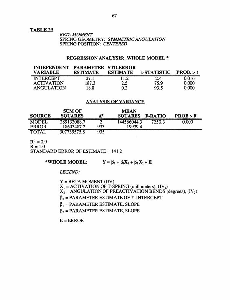
67
TABLE 29BETA MOMENTSPRING GEOMETRY: SYMMETRICANGULATIONSPRING POSITION: CENTERED
REG.RESSION ANALYSIS: WHOLE MODEL *
INDEPENDENT PARAMETER STD.ERRORVARIABLE ESTIMATE ESTIMATEINTERCEPT 27’.1 li.2ACTIVATION 187.3 2.5ANGULATION 18.8 0.2
t.STATISTIC" 2.4
75.993.5
PROB. > t0.0160.0000.000
ANALYSIS OF VARIA,N,CE
SUM OFSOURCE SQUARES d,f,MODEL ’289132088.7 2ERROR 18603487.2 933’TOTAL 307’735575.8 935
MEANSQUARES F-RATIO144566044.3 7250.)
19939.4
R2 = 0.9R=I.0STANDARD ERROR OF ESTIMATE = 141.2
PROB > F0,000
*WHOLE MODEL: Y = 0 + 3,X, + [z Xz + E
LEGEND:
Y = BETA MOMENT (DV)Xx = ACTIVATION OF T-SPRING (millimeters), (IVy)X: = ANGULATION OF PREACTIVATION BENDS (degrees), (IV:)o = PARAMETER ESTIMATE OF Y-INTERCEPT
x = PARAMETER ESTIMATE, SLOPE
2 = PARAMETER ESTIMATE, SLOPE
E = ERROR
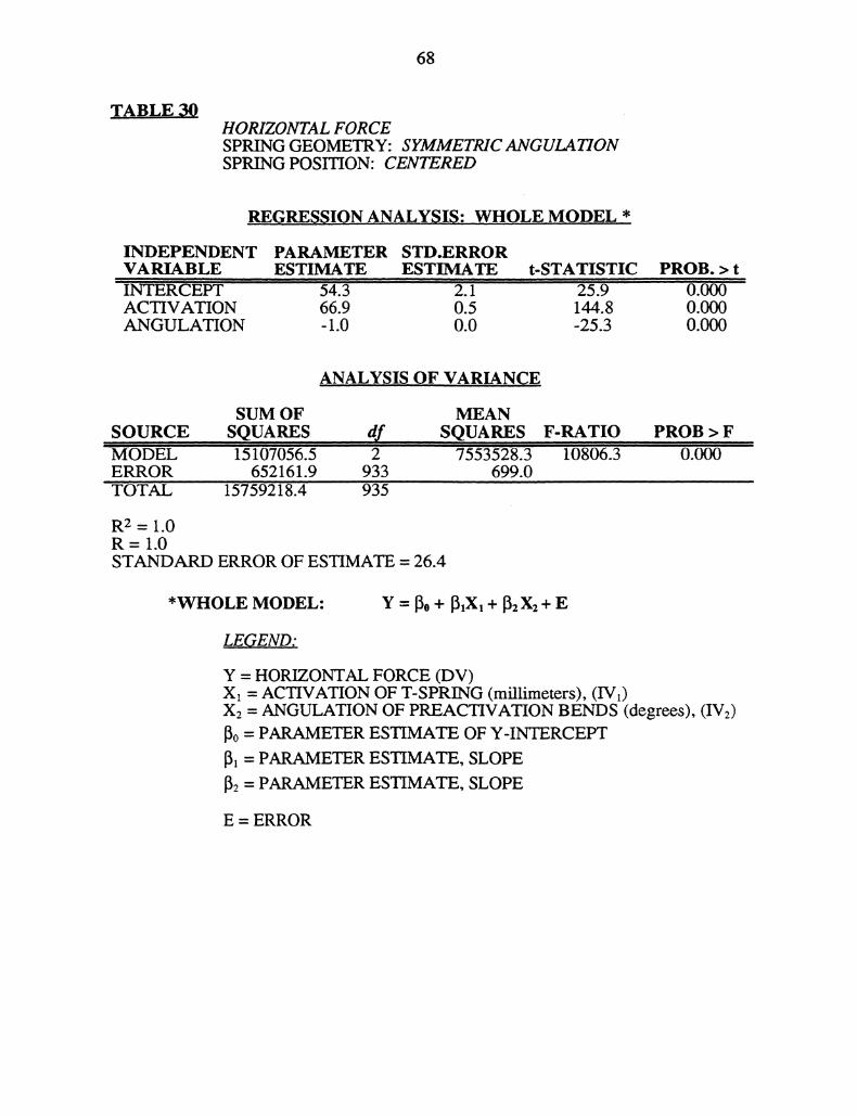
68
TABLE 30HORIZONTAL FORCESPRING GEOMETRY: SYMMETRICANGULATIONSPRING POSITION: CENTERED
REGRE,SSION ANALYSIS,: WHOLE MODEL .*
INDEPENDENT PARAMETER STD.ERRORVARIABLE ESTIMATE ESTIMATE t-STATISTIC’iERCET 54.’ 2.i 259ACTIVATION 66.9 0.5 144.8ANGULATION 1.0 0.0 -25.3
PROB. > t
0.0000.000
ANALYSIS OF VARIANCE
SUM OF MEANSOURCE SQUARES df SQUARESMODEL 151’07056.5 2 7’5535283ERROR 652161.9 933 699.0TOTAL 15759218.21. 935
R2= 1.0R- 1.0STANDARD ERROR OF ESTIMATE 26.4
F-RATIO 68o6.3" "
PROB > F
*WHOLE MODEL" Y = o + ]3,X, + zXz + E
LEGEND:
Y = HORIZONTAL FORCE (DV)X = ACTIVATION OF T-SPRING (millimeters), (IVy)X2 = ANGULATION OF PREACTIVATION BENDS (degrees), (IV2)[o = PARAMETER ESTIMATE OF Y-INTERCEPT= PARAMETER ESTIMATE, SLOPE= PARAMETER ESTIMATE, SLOPE
E- ERROR
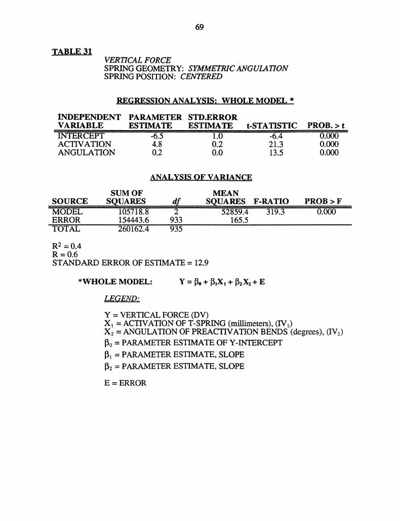
69
TABLE 31VER7ICAL FORCESPRING GEOMETRY: SYMMETRICANGULATIONSPRING POSITION: CENTERED
_REGRESSION.ANALYSIS: W.HOLE,MODEL *INDEPENDENTVARIABLE-iNTERCEPACTIVATIONANGULATION
PARAMETER STD.ERRORESTIMATE ESTIMATE
I-6.5 1.04.8 0.20.2 0.0
t-STATISTIC’-6.421.313.5
PROB. > t
0.0000.000
ANALYSIS,OF V..ARIANCE
SUM OF MEANSOURCE SQUARES .dr SQUARESMODEL 1057 8.8 2 52859.4ERROR 154443.6 933 165.5TOTAL" 2601i52.4 935
F-RATIO3i9,3
PROB > F0.000
R2 = 0.4R=0.6STANDARD ERROR OF ESTIMATE = 12.9
*WHOLE MODEL: Y - o -b lX1-1- 2X2 "b E
LEGEND:
Y = VERTICAL FORCE (DV)X = ACTIVATION OF T-SPRING (millimeters), (IVy)X2 = ANGULATION OF PREACTIVATION BENDS (degrees), (IVy)
o = PARAMETER ESTIMATE OF Y-INTERCEPT
x = PARAMETER ESTIMATE, SLOPE[2 = PARAMETER ESTIMATE, SLOPE
E = ERROR
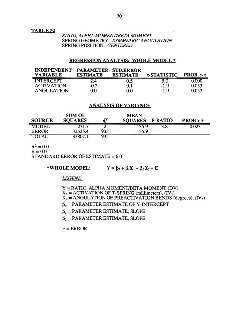
70
TABLE 32RATIO, ALPHA MOMENT/BETA MOMENTSPRING GEOMETRY: SYMMETRICANGULATIONSPRING POSITION: CENTERED
,.REGRESSION ANALYSIS:, WHOLE MODEL *
INDEPENDENTVARIABLE,INTERCli3,ACTIVATIONANGULATION
PARAMETER STD.ERRORESTIMATE ESTIMATE t-STATISTIC
2.4 0.’5 5’.6’-0.2 0.1 -1.90.0 0.0 -1.9
PROB. > t0.0000.0530.052
ANALYS.IS,.OF VARIANCE
SUM OFSOURCE SQUARES dr.MODEL 27117 2ERROR 33535.4 933"IOTAL 33807.1 95
MEANSQUARES F-RATIO
’I|
135.9 3.835.9
R2 = 0.0R -0.0STANDARD ERROR OF ESTIMATE = 6.0
PROB > F0.o 3
*WHOLE MODEL" Y = Io + I3,X, + 2 X2 "1" E
LEGEND:
Y = RATIO, ALPHA MOMENT/BETA MOMENT (DV)Xx = ACTIVATION OF T-SPRING (millimeters), (IVt)X2 = ANGULATION OF PREACTIVATION BENDS (degrees), (IV2)[3o = PARAMETER ESTIMATE OF Y-INTERCEPTl PARAMETER ESTIMATE, SLOPE
1 = PARAMETER ESTIMATE, SLOPE
E = ERROR

71
TABLE 33ALPHA MOMENTSPRING GEOMETRY: SYMMETRICMOMENTSSPRING POSITION: OFF-CENTERED
REGRESSION ANALYSIS: WHOLE MODEL *
INDEPENDENT PARAMETER STD.ERRORVARIABLE ESTIMATE ESTIMATE t-STATISTIC PROB. > tINTERCEPT 1135.2 16.1 -70.3 0.000POSITION 252.3 3.3 75.5 0.000ACTIVATION 147.5 4.6 -32.3 0.000
ANALY.SIS OF VARIANCE
SUM OF MEANSOURCE SQUARES df SQUARES F-RATIO PROB > FMODEL 513138554.2 2 256569277.1 3377.6 0.000ERROR 78772214.8 1037 75961.6TOTAL 5919’10769.0 1’039
R2 -0.9R=0.9STANDARD ERROR OF ESTIMATE = 275.6
*WHOLE MODEL- Y = [o + X, + [z X2 + E
LEGEND:
Y = ALPHA MOMENT (DV)X = ,SPRING POSITION, (millimeters from center position), (IVy)
(negative values are toward anterior)X2 = ACTIVATION OF T-SPRING (millimeters), (IV2)13o = PARAMETER ESTIMATE OF Y-INTERCEPTI = PARAMETER ESTIMATE, SLOPE13. = PARAMETER ESTIMATE, SLOPE
E = ERROR

72
TABLE 34BETA MOMENTSPRING GEOMETRY: SYMMETRIC MOMENTSSPRING POSITION: OFF- CENTER
REGRESSION ANALYSIS: WHOLE MODEL *
INDEPENDENTVARIABLE
,-"
INTERCEPTPOSITIONACTIVATION
PARAMETER STD.ERRORESTIMATE ESTIMATE t-STATISTIC
1H4.2 14.6 76.2222.9 3.0 73.7164.3 4.1 39.7
PROB. > t0o0000.0000.000
..ANALYSIS OF VARIA.NC.,.E
SUM OF MEANSOURCE ,,SQUARES df SQUARESMODEL 435759924.4 2 217879962.2ERROR 64534900.2 1037 62232.3TOTAL 50029,824.6 1039
R- = 0.9R=0.9STANDARD ERROR OF ESTIMATE = 249.5
F-RATIO3501.1
PROB > Fo.oo0
*WHOLE MODEL- Y = o +X + zXz + E
LEGEND:
Y = BETA MOMENT (DV)X = ,SPRING POSITION, (millimeters from center position), (IV1)
(negative values are toward anterior)X2 = ACTIVATION OF T-SPRING (millimeters), (IVz)15o = PARAMETER ESTIMATE OF Y-INTERCEPT1]1 = PARAMETER ESTIMATE, SLOPE
13 = PARAMETER ESTIMATE, SLOPE
E = ERROR
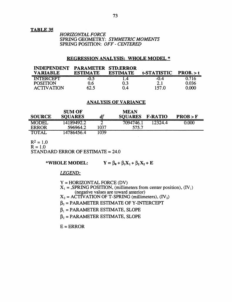
73
TABLE 35HORIZONTAL FORCESPRING GEOMETRY: SYMMETRICMOMENTSSPRING POSITION: OFF- CENTERED
_REGRESSION ANALYSIS: WHOLE MODEL,,,
INDEPENDENTVARIABLE
POSITIONACTIVATION
PARAMETER STD.ERRORESTIMATE ESTIMATE t-STATISTIC
’" ’-0.5 14’’ -0.40.6 0.3 2.162.5 0.4 157.0
PROB. > t0.7i6’’0.0360.000
,.ANALYSIS OF V.ARIANCE
SUM OF MEANSOURCE, SQUARES df SQUARESMODEL 14189492.2 2 7094746.1ERROR 596964.2 1037 575.7TOTAL 14786456.4 1039
R2 = 1.0R= 1.0STANDARD ERROR OF ESTIMATE = 24.0
F-RATIO12324.4
PROB > F0.000
*WHOLE MODEL: 13o + + + E
LEGEND:
Y = HORIZONTAL FORCE (DV)X = ,SPRING POSITION, (millimeters from center position), (IVy)
(negative values are toward anterior)X2 = ACTIVATION OF T-SPRING (millimeters), (IVy)
lo = PARAMETER ESTIMATE OF Y-INTERCEPT13 = PARAMETER ESTIMATE, SLOPE
2 = PARAMETER ESTIMATE, SLOPE
E = ERROR

74
TABLE 36VER1"1CAL FORCESPRING GEOMETRY: SYMMETRICMOMENTSSPRING POSITION: OFF- CENTERED
REGRESSION ANALYSIS" WHOLE MODEL *
INDEPENDENT PARAMETERVARIABLE ESTIMATEINTERCEPT 9.0POSITION 24.3ACTIVATION 2.4
STD.ERRORESTIMATE t-STATISTIC PROB. > t,_,
1.2 7.7 0.0000.2 100.2 0.0000.3 7.4 0.000
ANALYSI,S OF VARIANCE
SUM OF MEANSOURCE SQUARES ,,dr,,, SQUA,RESMODEL 14189492.2 2 7094746.1ERROR 596964.2 1037 575.7TOTAL ’14786456.4 1039
R2 = 1.0R= 1.0STANDARD ERROR OF ESTIMATE- 20.0
F-RATIO12324.4
PROB > F
*WHOLE MODEL- Y = Io + X + 2X2 + E
LEGEND:
Y = VERTICAL FORCE (DV)X = ,SPRING POSITION, (millimeters from center position), (IV x)
(negative values are toward anterior)X2 = ACTIVATION OF T-SPRING (millimeters), (IV2)[0 = PARAMETER ESTIMATE OF Y-INTERCEPT[ = PARAMETER ESTIMATE, SLOPE
12 = PARAMETER ESTIMATE, SLOPE
E = ERROR
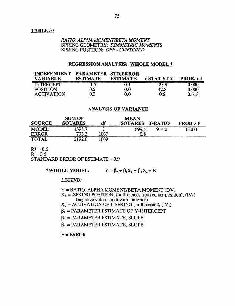
75
TABLE 37
RATIO, ALPHA MOMENT/BETA MOMENTSPRING GEOMETRY: SYMMETRICMOMENTSSPRING POSITION: OFF- CENTERED
REGRESSION ANALYSIS: WHQLE MODEL,, *
INDEPENDENT PARAMETER STD.ERRORVARIABLE ESTIMATE ESTIMATE t-STATISTIC"’INTERCEPT 1.5 0.1 -28.9POSITION 0.5 0.0 42.8ACTIVATION 0.0 0.0 0.5
PROB. > t0.0000.0000.613
_ANALYSIS OF VARIANCESUM OF MEAN
SOURCE SQUARES df SQUARES F-RATIOMODEL ""1398. 2 699.4 ’914.2ERROR 793.3 1037 0.8TOTAL 2192.0 "1039
R2 -0.6R=0.6STANDARD ERROR OF ESTIMATE = 0.9
PROB > F0.000
*WHOLE MODEL: Y = o + ,X, + zXz + E
LEGEND;
Y = RATIO, ALPHA MOMENT/BETA MOMENT (DV)X = ,SPRING POSITION, (millimeters from center position), (IV)
(negative values are toward anterior)X: = ACTIVATION OF T-SPRING (millimeters), (IV:)13o PARAMETER ESTIMATE OF Y-IN’IRCEPT
13 PARAMETER ESTIMATE, SLOPE
: = PARAMETER ESTIMATE, SLOPE
E = ERROR

76
TABLE 38ALPHA MOMENTSPRING GEOMETRY: ASYMMETRICANGULATION
ALPHA ANGULATION : O, 15, 30, 45,60 degreesBETA ANGULATION: 75 degree/s
SPRING POSITION: CENTERED
REGRESSION ANALYSIS:, WHOLE MODEL *
INDEPENDENT PARAMETER STD.ERRORVARIABLE ESTIMATE ESTIMATEINTERCEPT " ’40’6.0 12.6’’ANGULATION** -22.0 0.3ACTIVATION -158.4 2.9
t-STATISTIC32.2-87.6-55.5
PROB. > t
0.0000.000
ANALYSIS,OF VARIANCE
SUM OFSOURCE SQUARESMODEL 17920891’7.2 2ERROR 9693543.8 582TOTAL 1’70822713.4 584
MEANSQUARES F-RATIO89604458.6 5379.8
16655.6
R2 = 0.9R =0.9STANDARD ERROR OF ESTIMATE = 129.1
PROB > F
*WHOLE MODEL: Y = Io + [,X, + Iz X2 "i" E
LEGEND:
Y = ALPHA MOMENT (DV)Xa = ANGULATION OF PREACTIVATION BENDS, ALPHA
ANGLE (degrees), (IVy)X: = ACTIVATION OF T-SPRING (millimeters), (IVy.)
Io = PARAMETER ESTIMATE OF Y-INTERCEPT
I = PARAMETER ESTIMATE, SLOPE
12 = PARAMETER ESTIMATE, SLOPE
E = ERROR
**ANGULATION refers to the alpha angle (See Legend, X).
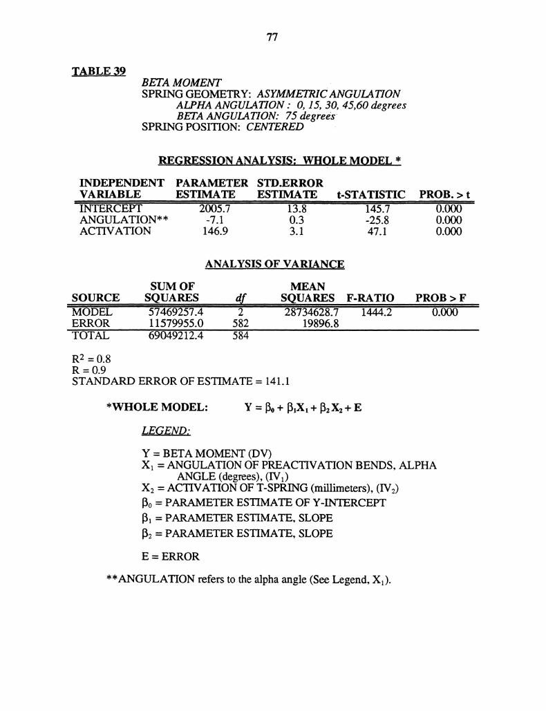
77
TABLE 39BETA MOMENTSPRING GEOMETRY: ASYMMETRICANGULATION
ALPHA ANGULATION : O, 15, 30, 45,60 degreesBETA ANGULATION: 75 degrees
SPRING POSITION: CENTERED
REGRESSION ANALYSIS; WHOLE MODEL *
INDEPENDENTVARIABLEIITERCEPTANGULATION**ACTIVATION
PARAMETER STD.ERRORESTIMATE ESTIMATE t-STATISTIC
2005’.7 13.8 145.7’-7.1 0.3 -25.8146.9 3.1 47.1
PROB. > t0.0000.0000.000
ANALYSIS OF VARIANCESUM OF
SOURCE SQUARES’MODEL 5746925’.4ERROR 11579955.0TOTAL 69049212.4
MEANdf SQUARES F-RATIO2 28’734628.7 ’1444.2
582 19896.8
R2 =0.8R =0.9STANDARD ERROR OF ESTIMATE = 141.1
PROB > F0.000
*WHOLE MODEL: Y = 13o + 13X + 13 X2 + E
LEGEND:
Y = BETA MOMENT (DV)Xx = ANGULATION OF PREACTIVATION BENDS, ALPHA
ANGLE (degrees), (IVy)X2 = ACTIVATION OF T-SPRING (millimeters), (IV2)13o = PARAMETER ESTIMATE OF Y-INTERCEPT13 = PARAMETER ESTIMATE, SLOPE
13: = PARAMETER ESTIMATE, SLOPE
E = ERROR
**ANGULATION refers to the alpha angle (See Legend, Xa).
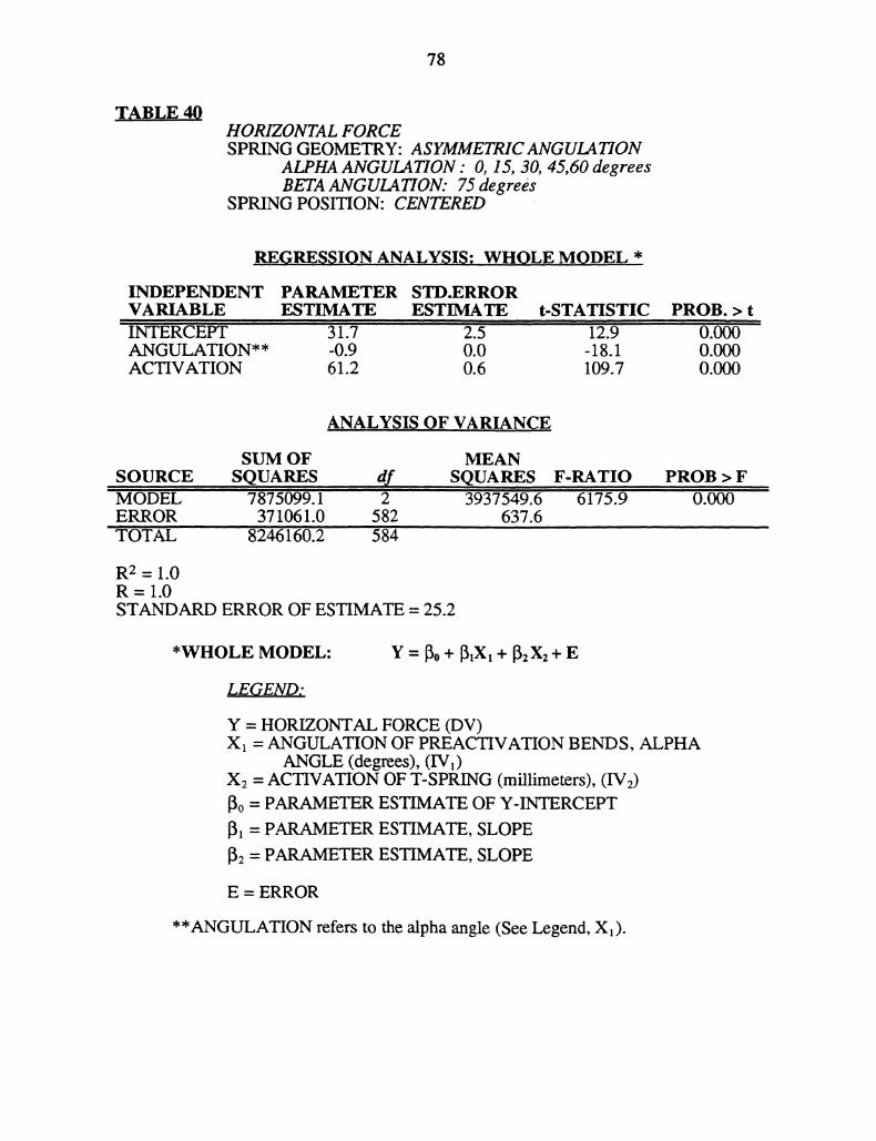
78
TABLE 40HORIZONTAL FORCESPRING GEOMETRY: ASYMMETRICANGULATION
ALPHA ANGULATION" O, 15, 30, 45,60 degreesBETA ANGULATION: 75 degrees
SPRING POSITION: CENTERED
REGRESSION ANALYSIS: WHOLE MODEL *
INDEPENDENTVARIABLEI"NTERCPTANGULATION**ACTIVATION
PARAMETER STD.ERRORESTIMATE ESTIMATE t-STATISTIC
31.7 2.5 12.9-0.9 0.0 -18.161.2 0.6 109.7
PROB. > t0.0000.0000.000
ANALYSIS OF VARIANCE
SUM OFSOURCE SQUARES dfIIODEL 787099.1 2ERROR 371061.0 582TOTAL 824’6160.2 584
MEANSQUARES F-RATIO PROB > F39’7549.6 6175.9
637.6
R2 = 1.0R=I.0STANDARD ERROR OF ESTIMATE = 25.2
*WHOLE MODEL" Y [30 + [31X + [32 X2 + E
LEGEND:
Y = HORIZONTAL FORCE (DV)Xx = ANGULATION OF PREACTIVATION BENDS, ALPHA
ANGLE (degrees), (IVy)X: = ACTIVATION OF T-SPRING (millimeters), (IV2)o = PARAMETER ESTIMATE OF Y-INTERCEPT13 = PARAMETER ESTIMATE, SLOPE
2 = PARAMETER ESTIMATE, SLOPE
E = ERROR
**ANGULATION refers to the alpha angle (See Legend, X).
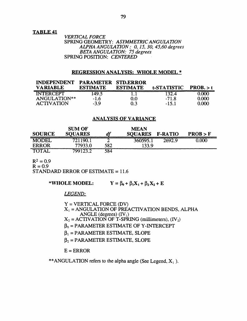
79
TABLE 41VERTICAL FORCESPRING GEOMETRY" ASYMMETRICANGULATION
ALPHA ANGULATION O, 15, 30, 45,60 degreesBETA ANGULATION: 75 degrees
SPRING POSITION: CENTERED
REGRESS_ION ANALYSIS: WH0.LE MODEL *
INDEPENDENT PARAMETER STD.ERRORVARIABLE ESTIMATE ESTIMATE t-STATISTICINTERCEPT 14915’ 1.1 132.4ANGULATION** 1.6 0.0 -71.8ACTIVATION -3.9 0.3 -15.1
PROB. > t0.0000.0000.000
ANALYSIS OE,,VARIANCE
SUM OFSOURCE SQUARES
.11
MODEL 721 i90.]ERROR 77933.0TOTAL 7991’23.2
MEANdf SQUARES, F-RAT.IO2 360595.1 "2692.9
582 133.9584
R2 = 0.9R =0.9STANDARD ERROR OF ESTIMATE = 11.6
PROB > Fo ooo
*WHOLE MODEL: Y = Io + X, + 2X2 + E
LEGEND:
Y = VERTICAL FORCE (DV)X = ANGULATION OF PREACTIVATION BENDS, ALPHA
ANGLE (degrees) (IVy)X. = ACTIVATION OF T-SPRING (millimeters), (IV2)1o = PARAMETER ESTIMATE OF Y-INTERCEPT
1 = PARAMETER ESTIMATE, SLOPE
I: = PARAMETER ESTIMATE, SLOPE
E ERROR
**ANGULATION refers to the alpha angle (See Legend, X ).
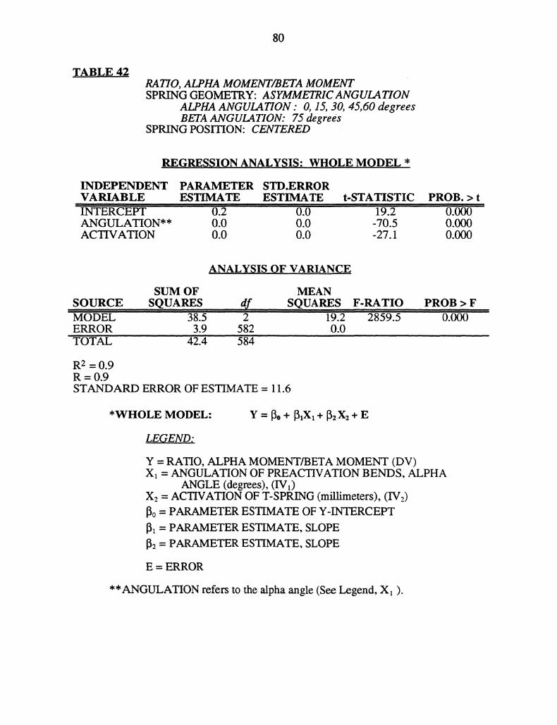
80
TABLE 42RATIO, ALPHA MOMENT/BETA MOMENTSPRING GEOMETRY: ASYMMETRICANGULATION
ALPHA ANGULATION O, 15, 30, 45,60 degreesBETA ANGULATION: 75 degrees
SPRING POSITION: CENTERED
REGRESSION ANALYSIS- WHOLE MODEL *
INDEPENDENT PARAMETER STD.ERRORVARIABLE ESTIMATE ESTIMATE t-STATISTICINTERCEPT 0.2 0.0 19.2ANGULATION** 0.0 0.0 -70.5ACTIVATION 0.0 0.0 -27.1
PROB. > t0.0000.0000.000
ANALYSIS OF VARIANCE
SUM OF MEANSOURCE SQUARES df SQUARESMODEL 38.5 2 19.2ERROR 3.9 582 0.0TOTAL 42.4 584
F-RATIO2839.5
PROB > F0.000
R2 = 0.9R 0.9STANDARD ERROR OF ESTIMATE = 11.6
*WHOLE MODEL: Y = 13o + 13,X, + 2 X2 "{" E
LE..END:
Y = RATIO, ALPHA MOMENT/BETA MOMENT (DV)X = ANGULATION OF PREACTIVATION BENDS, ALPHA
ANGLE (degrees), (IVy)X2 = ACTIVATION OF T-SPRING (millimeters), (IV2)13o = PARAMETER ESTIMATE OF Y-INTERCEPT13 = PARAMETER ESTIMATE, SLOPE
1. = PARAMETER ESTIMATE, SLOPE
E = ERROR
**ANGULATION refers to the alpha angle (See Legend, X ).

81
TABLE 43ALPHA MOMENTSPRING GEOMETRY: ASYMMETRICANGULATION
ALPHA ANGULATION 75 degreesBETA ANGULATION: O, 15, 30,45,60 degrees
SPRING POSITION: CENTERED
REGRESSION ANALYSIS: WHOLE MODEL *
INDEPENDENTVARIABLEINTERCEPTANGULATION**ACTIVATION
PARAMETER STD.ERRORESTIMATE ESTIMATE t-STATISTIC
-2290.2 15.6 -146.86.7 0.3 21.5
-121.7 3.5 -34.5
PROB. > t0.0000.0000.000
ANAL.YSIS, OF V.ARIANCE
SUM OF MEANSOURCE SQUARES df SQUARESMODEL 42087382.3" 2 21043691.1ERROR 14871089.4 582 25551.7TOTAL 56958471.7 584
R2 =0.7R=0.7STANDARD ERROR OF ESTIMATE = 159.8
PROB > F0.000
*WHOLE MODEL: Y o + IlXl + 2X2 + E
LEGEND:
Y = ALPHA MOMENT (DV)X = ANGULATION OF PREACTIVATION BENDS, BETA
ANGLE (degrees), (IVt)X = ACTIVATION OF T-SPRING (millimeters), (IVy)
13o = PARAMETER ESTIMATE OF Y-INTERCEPT
13 = PARAMETER ESTIMATE, SLOPE
132 = PARAMETER ESTIMATE, SLOPE
E = ERROR
**ANGULATION refers to the beta angle (See Legend, X).

82
TABLE 44BETA MOMENTSPRING GEOMETRY: ASYMMETRICANGULATION
ALPHA ANGULATION : 75 degreesBETA ANGULATION: O, 15, 30,45,60 degrees
SPRING POSITION: CENTERED
,REGRESSION ANALYSIS; WHOLE MODEL *
INDEPENDENTVARIABLEINTERCEPT ’"ANGULATION**ACTIVATION
PARAMETER STD.ERRORESTIMATE ESTIMATE t-STATISTIC
"1194.7 26.9 "-44.531.1 0.5 58.0191.9 6.1 31.5
PROB. > t
0.0000.000
ANALYSIS OF .VARIANCE
SUM OF MEANSOURCE SQUARES df SQUARESMODEL ’330634062.7 2 ’65317031.3ERROR 44118485.1 582 75805.0TOTAL 37472547.8 584
R2 = 0.9R=0.9STANDARD ERROR OF ESTIMATE = 275.3
F-RATIO218018
PROB > F
*WHOLE MODEL: Y = [o + 13,Xx + zXz + E
LEGEND:
Y = BETA MOMENT (DV)X = ANGULATION OF PREACTIVATION BENDS, BETA
ANGLE (degrees), (IVy)X = ACTIVATION OF T-SPRING (millimeters), (IVy)
o = PARAMETER ESTIMATE OF Y-INTERCEPT
1 = PARAMETER ESTIMATE, SLOPE
2 = PARAMETER ESTIMATE, SLOPE
E = ERROR
**ANGULATION refers to the beta angle (See Legend, X).

83
TABLE 45HORIZONTAL FORCESPRING GEOMETRY: ASYMMETRICANGULATION
ALPHA ANGULATION 75 degreesBETA ANGULATION: O, 15, 30, 45,60 degrees
SPRING POSITION: CENTERED
.REGRESSION ANALYSIS: WHOLE MODEL *
INDEPENDENTVARIABLEIERCEPTANGULATION**ACTIVATION
PARAMETER STD.ERRORESTIMATE ESTIMATE t-STATISTIC
"" -104’ ’3.3 ’’’ -31"0.2 0.1 3.765.4 0.8 87.0
PROB. > t0.0020.0000.000
ANA.LYSIS ,OF VAR.I.NCE
SUM OFSOURCE ,,S.QUARESMODEL" 878406.1 ’’ERROR 674625.2TOTAL "9458693.3,
MEANdf SQUARES
439204.1582 1159.1584
F-RATIO"3789.0
R2 = 0.9R=0.9STANDARD ERROR OF ESTIMATE = 34.0
PROB > F
*WHOLE MODEL: Y = [o + X + 2X2 + E
LEGEND;
Y = HORIZONTAL FORCE (DV)X = ANGULATION OF PREACTIVATION BENDS, BETA
ANGLE (degrees), (IVy)X2 = ACTIVATION OF T-SPRING (millimeters), (IV:)Bo = PARAMETER ESTIMATE OF Y-INTERCEPT1 PARAMETER ESTIMATE, SLOPE
132 = PARAMETER ESTIMATE, SLOPE
E = ERROR
**ANGULATION refers to the beta angle (See Legend, Xx).

84
TABLE 46VERTICAL FORCESPRING GEOMETRY: ASYMMETRICANGULATION
ALPHA ANGULATION 75 degreesBETA ANGULATION: O, 15, 30,45,60 degrees
SPRING POSITION: CENTERED
,REGRESSION ANALYSIS: WHOLE MODEL *
INDEPENDENTVARIABLEIN;’rRCEPTANGULATION**ACTIVATION
PARAMETER STD.ERRORESTIMATE ESTIMATE t-STATISTIC
-192.4 1.8 -105.02.0 0.0 55.811.4 0.4 27.5
PROB. > t
0.0000.000
6NALYSIS ,,OF VARIA,NCE
SUM OFSOURCE, SQUARESMODEL 1364499.1ERROR 205102.0TO@AL 156960i.1
582584
MEANSQUARES F-RATIO
6822z9’.5 1936.0’35.2.4
R2 = 0.9R 0.9STANDARD ERROR OF ESTIMATE = 18.0
PROB > F0.000
*WHOLE MODEL" Y = 1o + Xx + X2 + E
LEGEND;
Y = VERTICAL FORCE (DV)X = ANGULATION OF PREACTIVATION BENDS, BETA
ANGLE (degrees), (IVy)X2 = ACTIVATION OF T-SPRING (millimeters), (IV2)o = PARAMETER ESTIMATE OF Y-INTERCEPT
= PARAMETER ESTIMATE, SLOPE
152 = PARAMETER ESTIMATE, SLOPE
E = ERROR
**ANGULATION refers to the beta angle (See Legend, X).
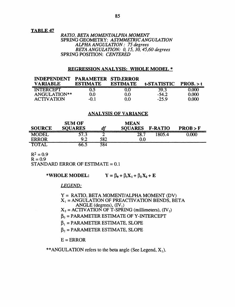
85
TABLE 47RA770, BETAMOMENTMOMENTSPRING GEOMETRY: ASYMMETRICANGULATION
ALPHA ANGULATION 75 degreesBETA ANGULATION: O, 15, 30, 45,60 degrees
SPRING POSITION: CENTERED
REGRESSION ANALYSIS: WHOLE MODEL *
INDEPENDENTVARIABLEiNTERCEPTANGULATION**ACTIVATION
PARAMETER STD.ERRORESTIMATE ESTIMATE t-STATISTIC
0.5 0.0 39.30.0 0.0 -54.2-0.1 0.0 -25.9
PROB. > t0.0000.0000.000
A.NALYSIS OF, VARIA,,NCE
SOURCEMODELERRORTOTAL
SUM OFSQUARES
57:39.2
66.5
MEAN,dr SQ.UA.RES2 287
582 0.0584
R2 = 0.9R=0.9STANDARD ERROR OF ESTIMATE = 0.1
F-RATIO1805.4
PROB > F0.000
*WHOLE MODEL: Y o + lXl + 2X2 + E
LEGEND:
Y = RATIO, BETA MOMENT/ALPHA MOMENT (DV)X: = ANGULATION OF PREACTIVATION BENDS, BETA
ANGLE (degrees), (IVy)X2 = ACTIVATION OF T-SPRING (millimeters), (IV2)[5o = PARAMETER ESTIMATE OF Y-INTERCEPT13 PARAMETER ESTIMATE, SLOPE
132 = PARAMETER ESTIMATE, SLOPE
E = ERROR
**ANGULATION refers to the beta angle (See Legend, Xl).
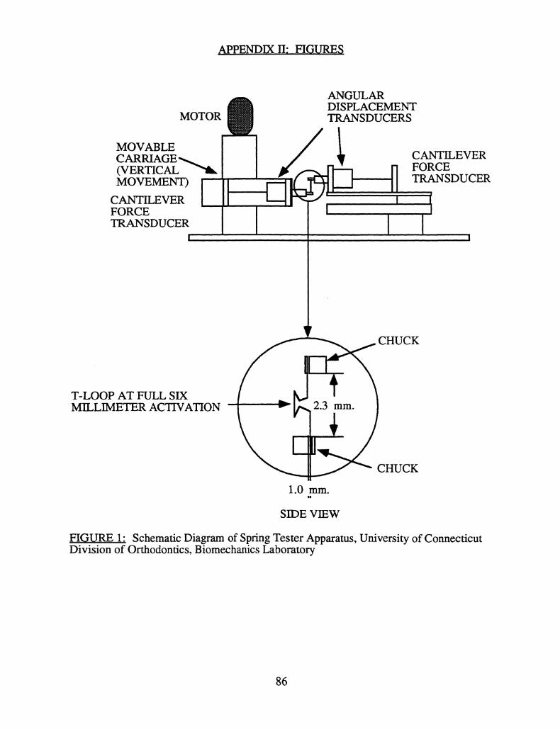
,_APPE,NDIX II: FIGURES
MOTOR
MOVABLECARRIAGE._(VERTICALMOVEMENT)
CANTILEVERFORCETRANSDUCER
ANGULARDISPLACEMENTTRANSDUCERS
CANTILEVERFORCETRANSDUCER
T-LOOP AT FULL SIXMILLIMETER ACTIVATION
CHUCK
CHUCK
SIDE VIEW
_FIGURE 1" Schematic Diagram of Spring Tester Apparatus, University of ConnecticutDivision of Orthodontics, Biomechanics Laboratory
86
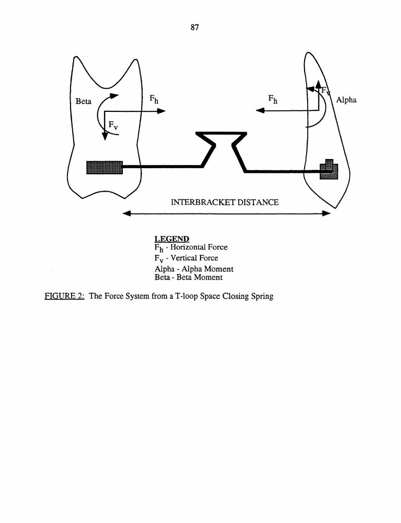
87
Beta Fh Fh Alpha
F
INTERBRACKET DISTANCE
LEGENDFh Horizontal ForceFv Vertical ForceAlpha- Alpha MomentBeta- Beta Moment
F!,GURE 2.,: The Force System from a T-loop Space Closing Spring
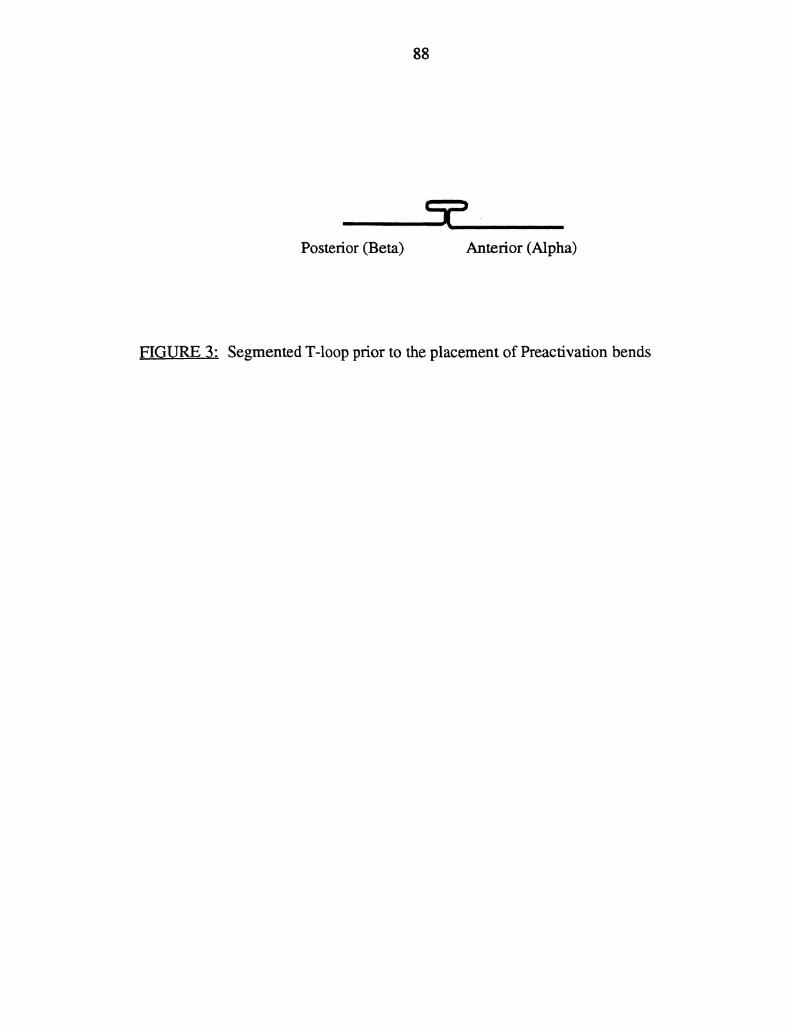
88
Posterior (Beta) Anterior (Alpha)
FIGURE 3: Segmented T-loop prior to the placement of Preactivation bends
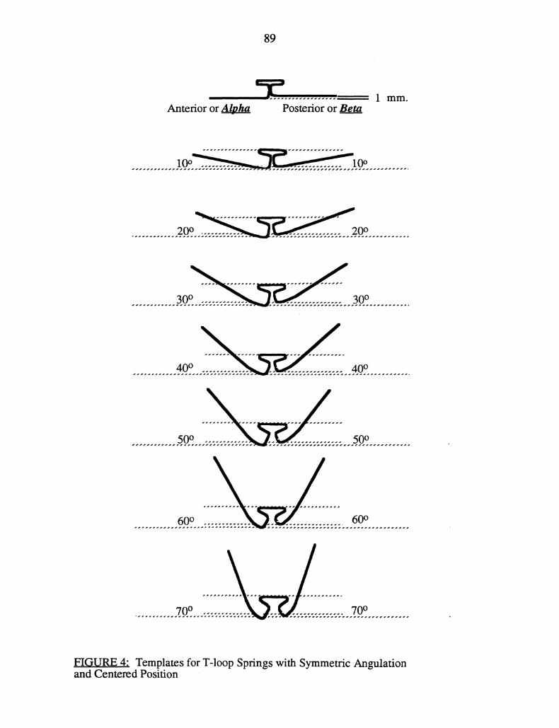
89
1mm.Anterior or Alpha Posterior or Beta
FIGURE 4: Templates for T-loop Springs with Symmetric Angulationand Centered Position
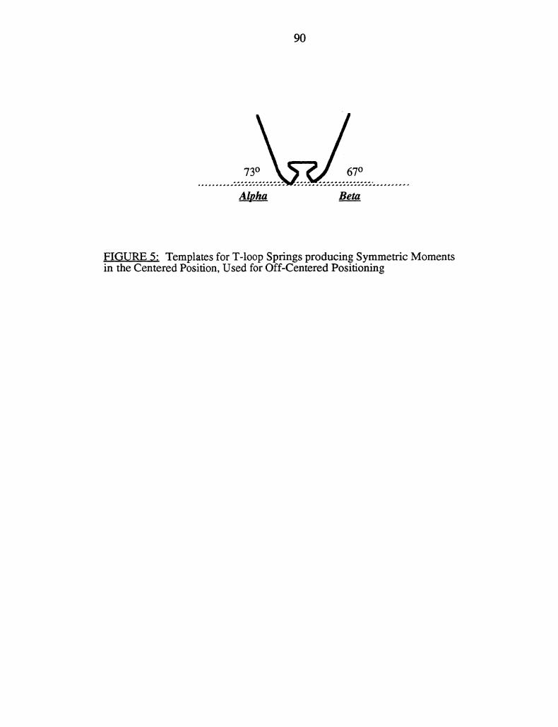
90
73 67
Alpha Beta
FIGURE 5" Templates for T-loop Springs producing Symmetric Momentsin the Centered Position, Used for Off-Centered Positioning
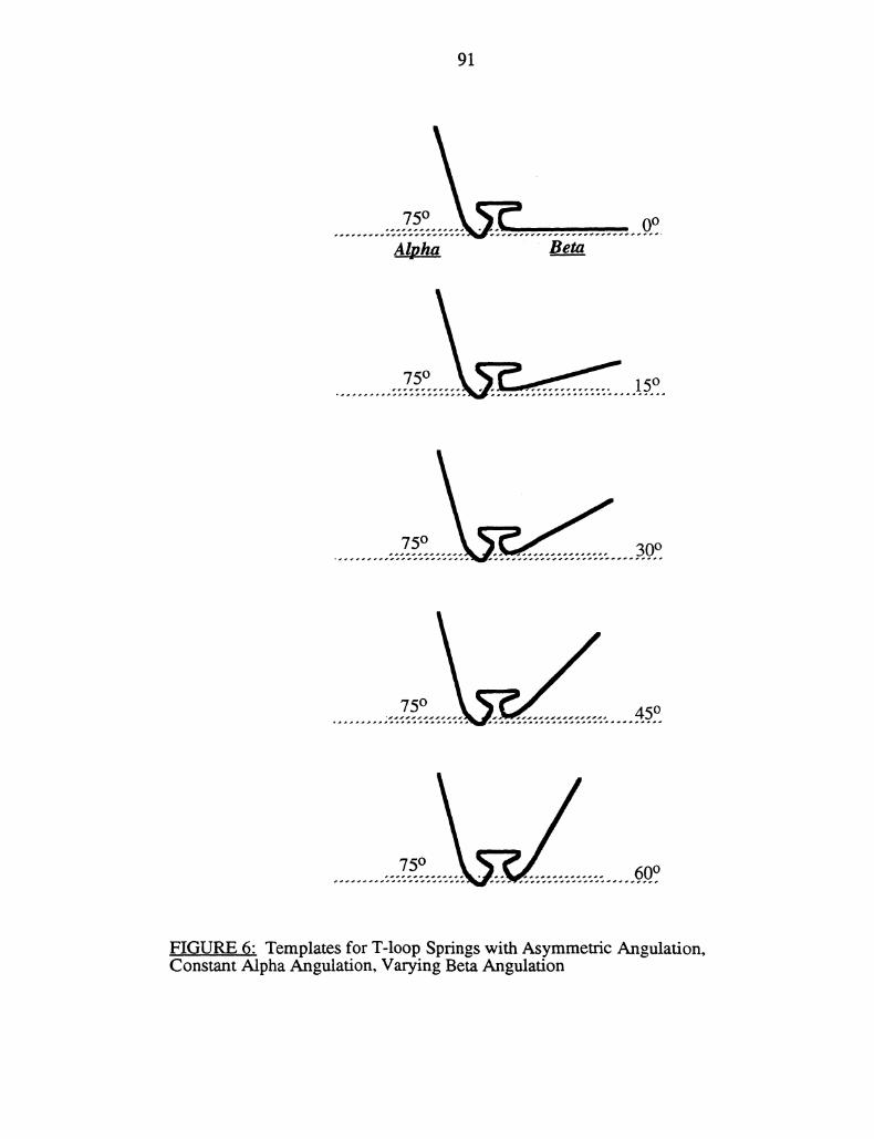
91
75 0o
Alpha Beta
....7..5 15
...7..5.. 30
45
60
FIGURE 6: Templates for T-loop Springs with Asymmetric Angulation,Constant Alpha Angulation, Varying Beta Angulation
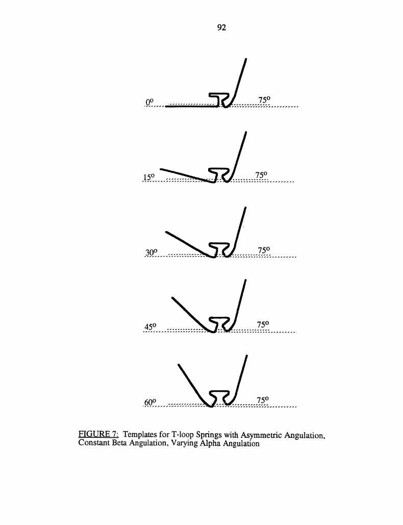
92
0o
751o
.FIGURE 7" Templates for T-loop Springs with Asymmetric Angulation,Constant Beta Angulation, Varying Alpha Angulation
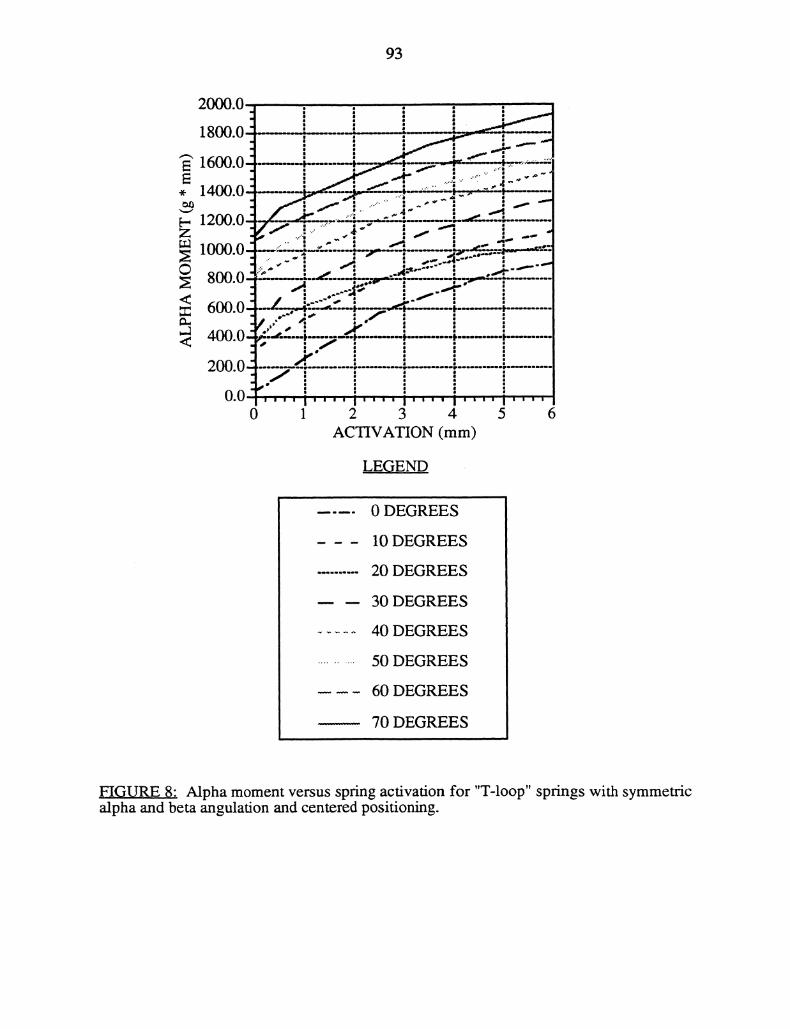
93
2000.0
1800.0
ACTIVATION (mm)
LEGEND
0 DEGREES
10 DEGREES
20 DEGREES
30 DEGREES
40 DEGREES
50 DEGREES
60 DEGREES
70 DEGREES
FIGURE 8" Alpha moment versus spring activation for "T-loop" springs with symmetricalpha and beta angulation and centered positioning.
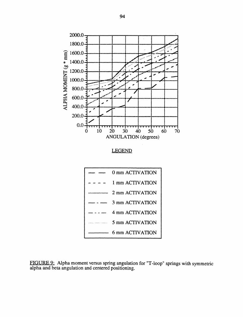
94
1800.0 s _-’ __....-___..,.:li
I’-----t .-.-----_1
"i ...’."
* 1400.0, -_............. .. W.-:’,-V--o..-" "’i ,-"
i I01’I/’./’ r .-’I ," j’,. ,.----.,-,,.,, ;.---_.-..----,..;.---,,[,
1000.0 .-’i----,,’-.-r_. -----,’o.-:.........-’.V’ ! ;_-1
i
IIlI I
I,I" _IF600.0- .--’V’-- /’--- /,,’
400.0"’ I__-----’--/ F +
200.0 --, _,,- * ."1]
0.0-- ......i,,,, ,,,,i ’,,,i,,,,,,,, i,,, ,i,,,0 10 20 30 40 50 60 70
ANGULATION (degrees)
LEGEND.
0 mm ACTIVATION
1 mm ACTIVATION
2 mm ACTIVATION
3 mm ACTIVATION
4 mm ACTIVATION
5 mm ACTIVATION
6 mm ACTIVATION
FIGURE 9" Alpha moment versus spring angulation for "T-loop" springs with symmetricalpha and beta angulation and centered positioning.
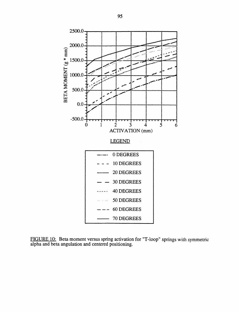
95
._....---’’-’--_..,IL...--’--2000.0
" _," ’!|_.-" ...... "--"-"--I .-
1500.0-
........ oee,I l I::."
r
5.0
0.0-, ’I’
0 1 2 3 4 5 6ACTWAON (mm)
LEGEND
0 DEGREES
10 DEGREES
20 DEGREES
30 DEGREES
40 DEGREES
50 DEGREES
60 DEGREES
70 DEGREES
FIGURE 10: Beta moment versus spring activation for "T-loop" springs with symmetricalpha and beta angulafion and centered positioning.
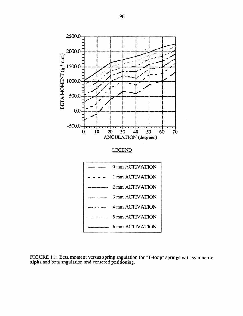
96
LEGE
0 mm ACVAON
1 mm ACVAON
2 mm ACVAON
3 mm ACVAON
4 mm ACTIVAON
5 mm ACVAON
6 mm ACVAON
FIGURE 11" Beta moment versus spring angulation foralpha and beta angulation and centered positioning.
"T-loop" springs with symmetric
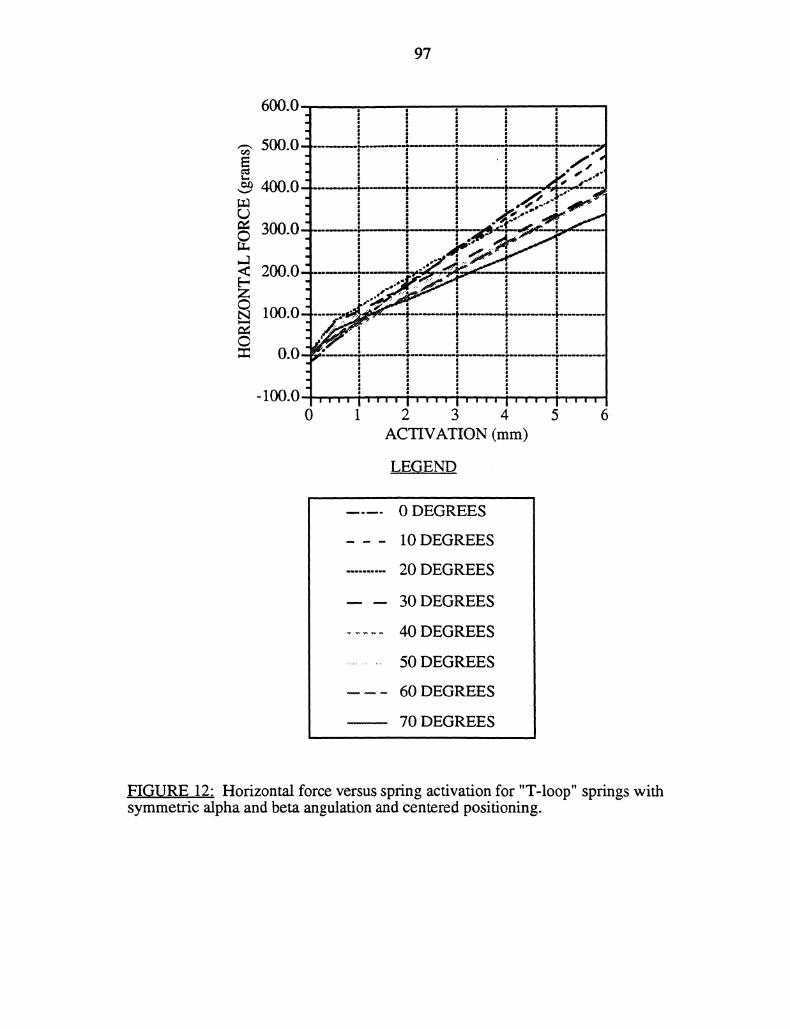
97
500.0--
4.0 ", -.0
-1.0..,.,,, i’"’ i’"’" i’’"’ ’"’’ i""’’0 1 2 3 4 5 6
ACVATION (ram)
LEGEND
0 DEGREES
10 DEGREES
20 DEGREES
30 DEGREES
40 DEGREES
50 DEGREES
60 DEGREES
70 DEGREES
FIGIRE 12" Horizontal force versus spring activation for "T-loop" springs withsymmetric alpha and beta angulation and centered positioning.
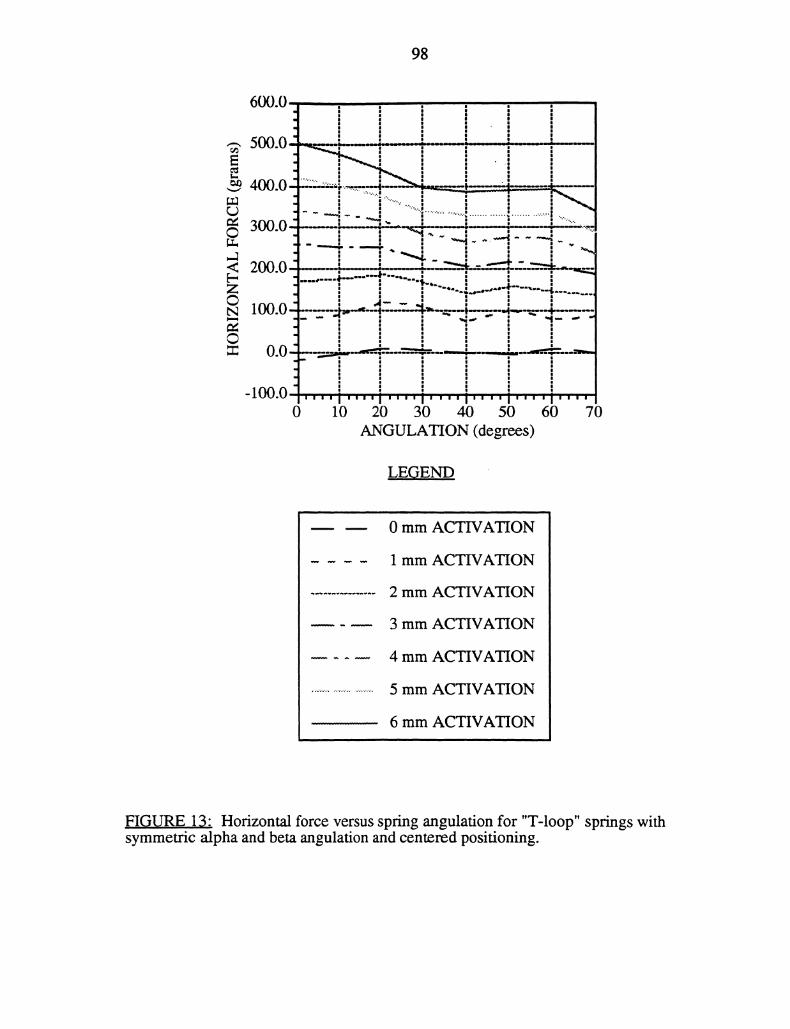
98
<Z0
0
LEOEND
0 mm ACTIVATION
1 mm ACTIVATION
2 mm ACTIVATION
3 mm ACTIVATION
4 mm ACTIVATION
5 mm ACTIVATION
6 mm ACTIVATION
EI_GURE 13" Horizontal force versus spring angulation for "T-loop" springs withsymmetric alpha and beta angulation and centered positioning.
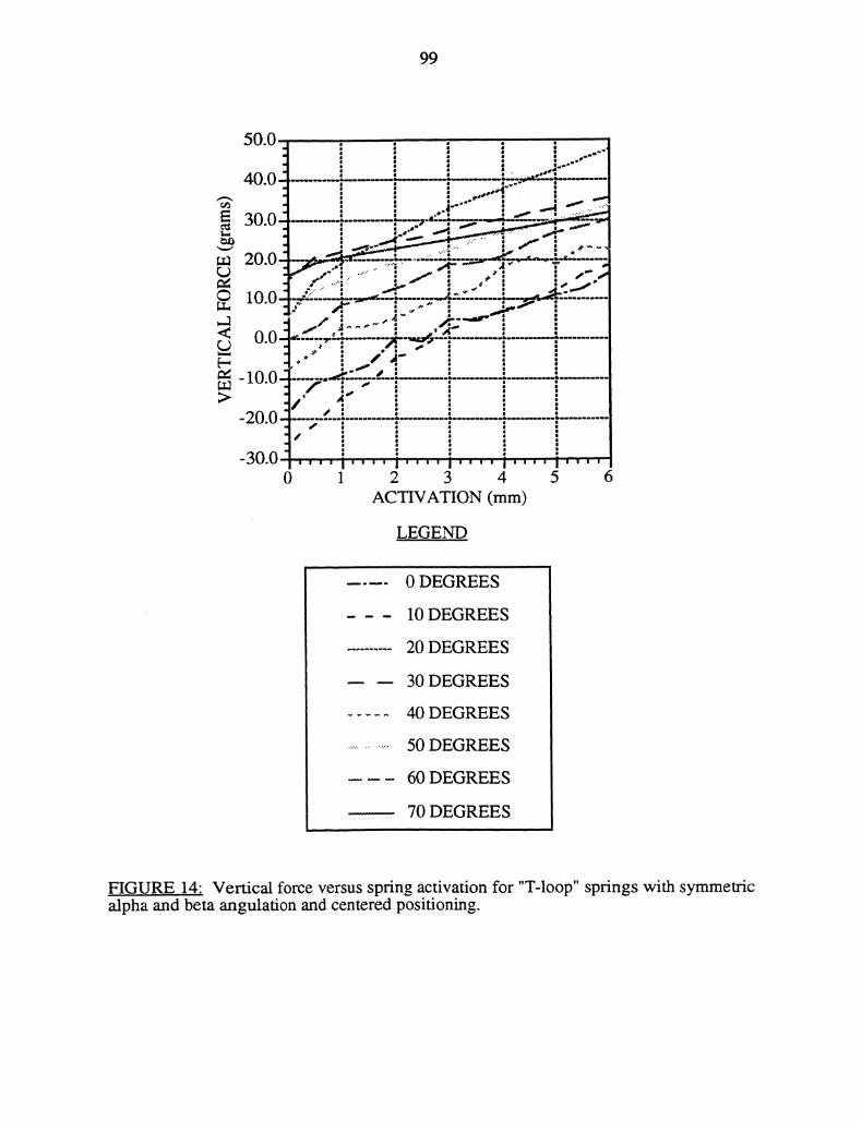
99
-20.0
-30.00
,
1 2 3 4 5 6ACTIVATION (mm)
LEGEND
0 DEGREES
10 DEGREES
20 DEGREES
30 DEGREES
40 DEGREES
50 DEGREES
60 DEGREES
70 DEGREES
FIGURE 14: Vertical force versus spring activation for "T-loop" springs with symmetricalpha and beta angulation and centered positioning.
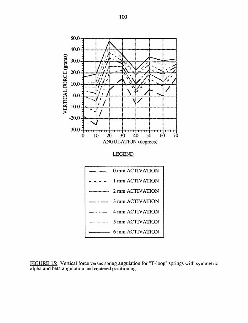
100
LEGEND
0 mm ACTIVATION
1 mm ACTIVATION
2 mm ACTIVATION
3 mm ACTIVATION
4 mm ACTIVATION
5 mm ACTIVATION
6 mm ACTIVATION
FIGURE 15" Vertical force versus spring angulation foralpha and beta angulation and centered positioning.
"T-loop" springs with symmetric
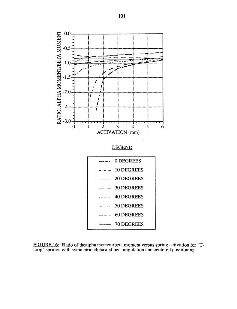
101
0.0
-1.0-"
-1.5
-2.0
-2.5
-3.00
_v’_*___’T_ _-"I__----..,:.T. -:.: .:-q .:.------ -;-;--: ,--- --,,;
’-".m,"’-"’-’-’
,-"1 .,-_,,;,!’.’--
., _1
";k+/- .[ [ k
.!’’’’ "’
1 2 3 4 5ACTIVATION (mm)
LEGEND
0 DEGREES
10 DEGREES
20 DEGREES
30 DEGREES
40 DEGREES
50 DEGREES
60 DEGREES
70 DEGREES
FIGURE 16: Ratio of thealpha moment/beta moment versus spring activation for "T-loop" springs with symmetric alpha and beta angulation and centered positioning.
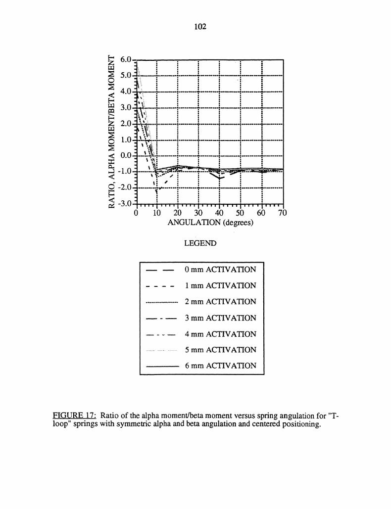
102
,iI;"
5.0
4.0-’::
Jl’.
3.0’’j..
2.0 :’:I"=ll 1:
,,I ;,.
l10 "-! p,j
"-I I.’.:0.0--.................................................,:I .:.p_ ;,._:_._:_ :___=
:i -- ,,’:
-2.0"I
-3.0 I,," ,,,,I I’ I’, i’"0 10 20 30 40 50 60 70
ANGULATION (degrees)
LEGEND
0 mm ACTIVATION
1 mm ACTIVATION
2 mm ACTIVATION
3 mm ACTIVATION
4 mm ACTIVATION
5 mm ACTIVATION
6 mm ACTIVATION
FI.GURE 17" Ratio of the alpha moment/beta moment versus spring angulation for "T-loop" springs with symmetric alpha and beta angulation and centered positioning.
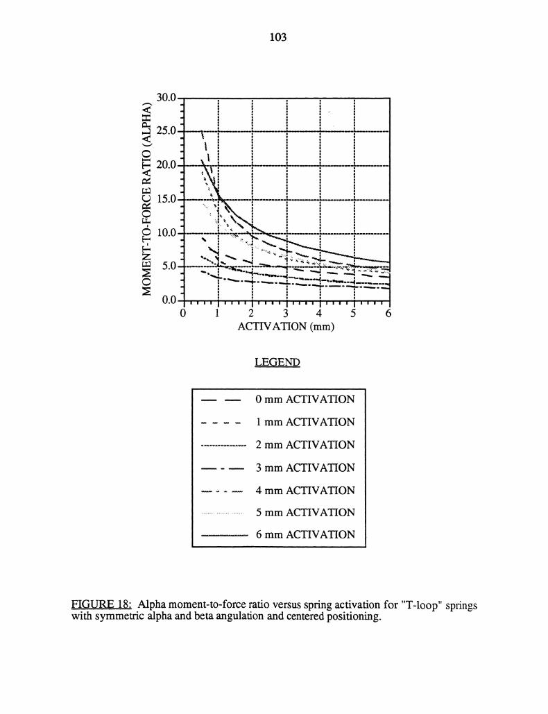
103
30.0
2.0--4
20.0--
15.0-- _10.0 b:’-’----
,.FN_
5.0 "
o.oi,, ., ..,.,,, ,,,, , ,, , ,.0 1 2 3 4 5 6
ACTAON (ram)
L.EGEND
0 mm ACTIVATION
1 mm ACTIVATION
2 mm ACTIVATION
3 mm ACTIVATION
4 mm ACTIVATION
5 mm ACTIVATION
6 mm ACTIVATION
FIGURE 18: Alpha moment-m-force ratio versus spring activation forwith symmetric alpha and beta angulation and centered positioning.
"T-loop" springs
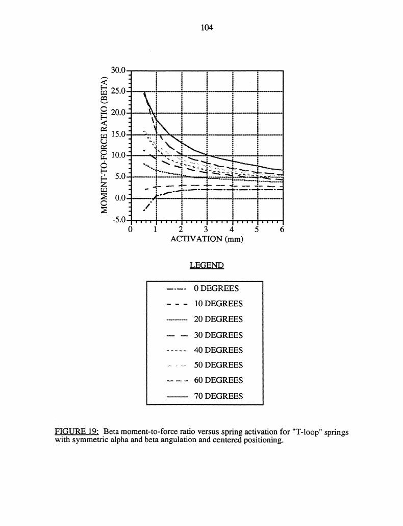
104
LEGEND
0 DEGREES
10 DEGREES
20 DEGREES
30 DEGREES
40 DEGREES
50 DEGREES
60 DEGREES
70 DEGREES
FIGURE 19: Beta moment-to-force ratio versus spring activation for "T-loop" springswith symmetric alpha and beta angulation and centered positioning.
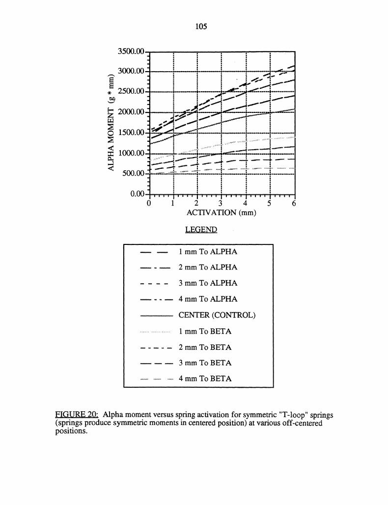
105
LEGEND
1 mm To ALPHA
2 mm To ALPHA
3 mm To ALPHA
4 mm To ALPHA
CENTER (CONTROL)
1 mm To BETA
2 mm To BETA
3 mm To BETA
4 mm To BETA
FIGURE 20: Alpha moment versus spring activation for symmetric "T-loop" springs(springs produce symmetric moments in centered position) at various off-centeredpositions.
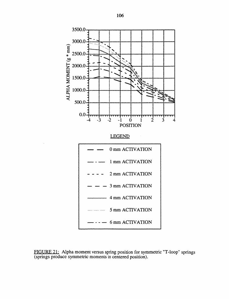
106
500.0 i
-4 -3 -2 1 0 1 2 3 4POSITION
LEGEND
0 mm ACTIVATION
1 mm ACTIVATION
2 mm ACTIVATION
3 mm ACTIVATION
4 mm ACTIVATION
5 mm ACTIVATION
6 mm ACTIVATION
FIGURE 2.1" Alpha moment versus spring position for symmetric "T-loop" springs(springs produce symmetric moments in centered position).
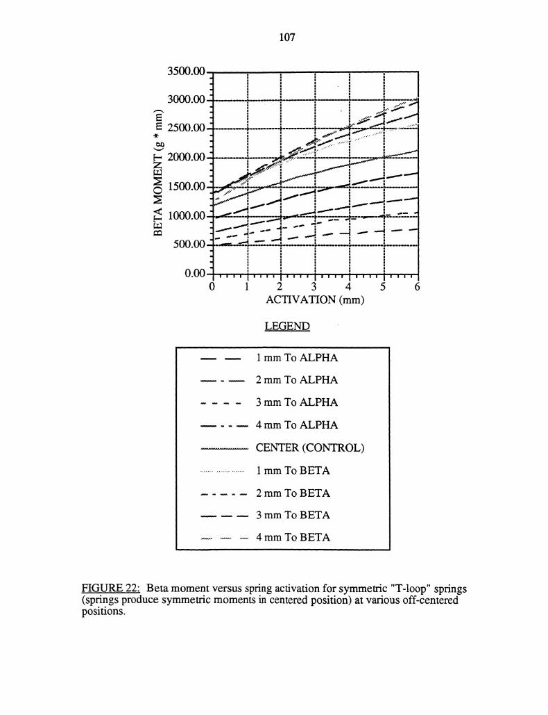
107
3500.00
3000.00
2500.00
2000.00
1500.00
ACTIVATION (mm)
LEGE..ND
1 mm To ALPHA
2 mm To ALPHA
3 mm To ALPHA
4 mm To ALPHA
CENTER (CONTROL)
1 mm To BETA
2 mm To BETA
3 mm To BETA
4 mm To BETA
FIGURE 22: Beta moment versus spring activation for symmetric "T-loop" springs(springs produce symmetric moments in centered position) at various off-centeredpositions.
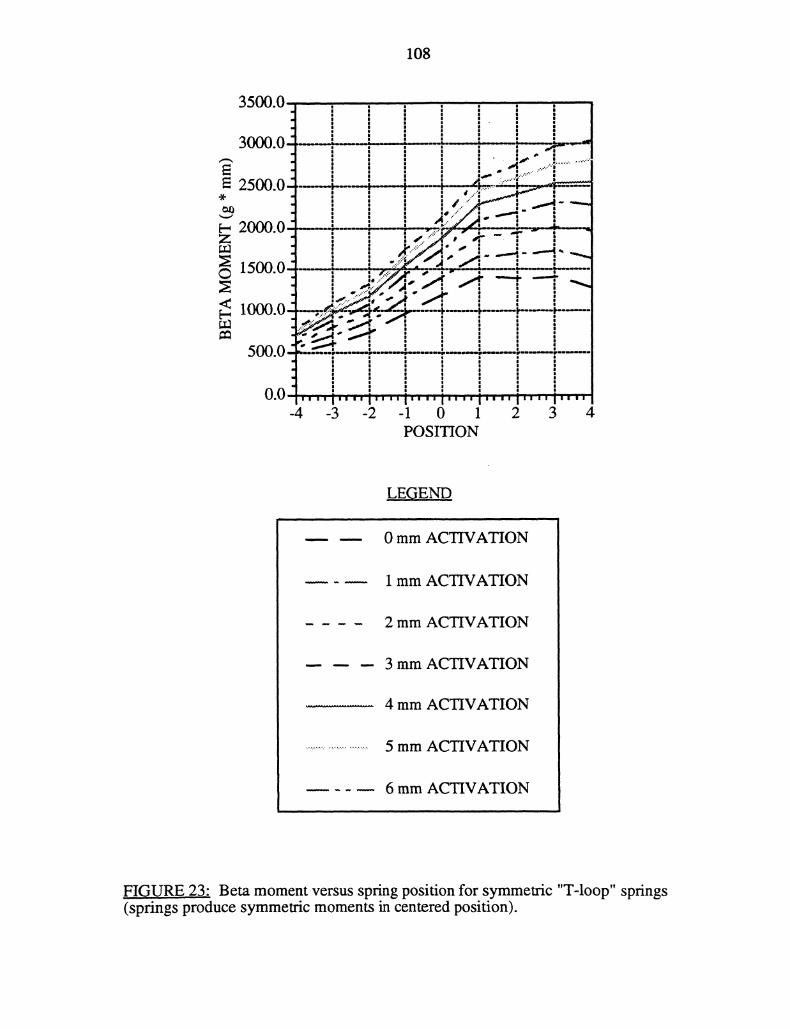
108
3500 0 I
30000 --1-
"1
,,- .....-.--:........’
")/M’WI fl ,.-’"/’.
;....... A /_:,nn n ...:---- .-_L---_L,.-.’4;’L "
..’:"
IoU
,,.._,..,-"T*
II
u.u/’""" I"" I" I’" I"" i" I" i""-4 -3 -2 -1 0 1 2 3 4
POSITION
LEGEND
0 mm ACTIVATION
1 mm ACTIVATION
2 mm ACTIVATION
3 mm ACTIVATION
4 mm ACTIVATION
5 mm ACTIVATION
6 mm ACTIVATION
FIGURE 23: Beta moment versus spring position for symmetric "T-loop" springs(springs produce symmetric moments in centered position).
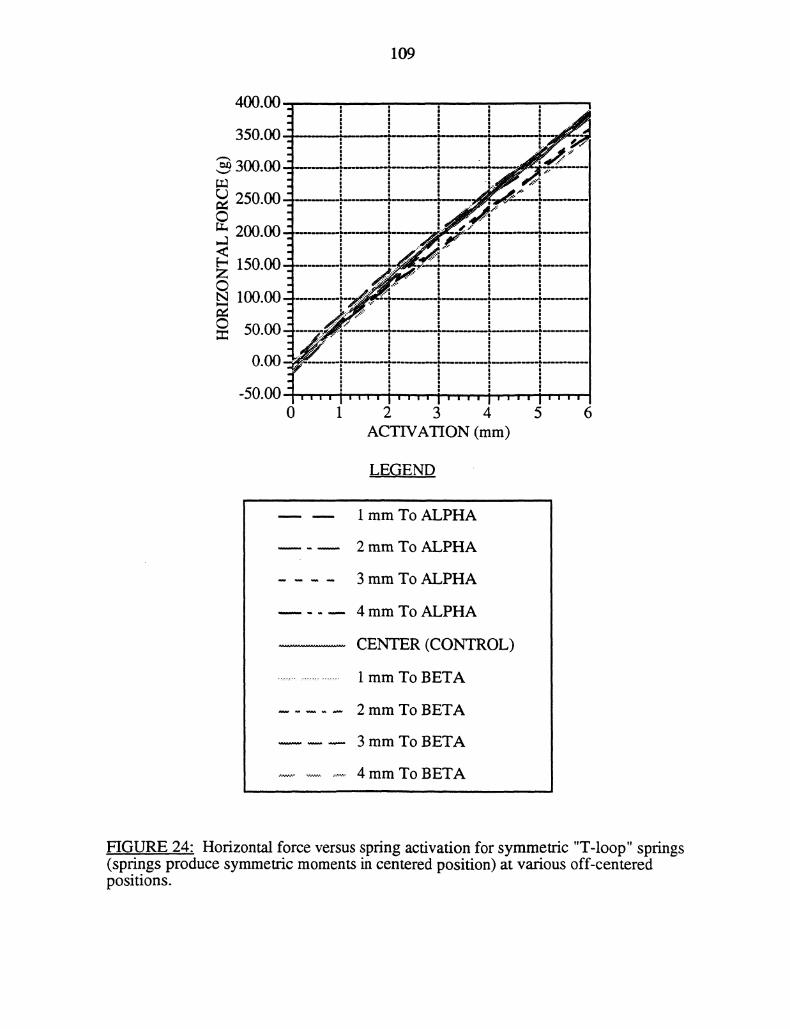
109
LEGEND
1 mm To ALPHA
2 mm To ALPHA
3 mm To ALPHA
4 mm To ALPHA
CENTER (CONTROL)
1 mm To BETA
2 mm To BETA
3 mm To BETA
4 mm To BETA
FIGURE 24" Horizontal force versus spring activation for symmetric "T-loop" springs(springs produce symmetric moments in centered position) at various off-centeredpositions.
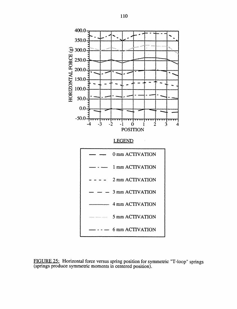
110
:-------. k........-_--.-
_...-,’"’-4 ""I ""I
l’l l’l l’l
-3 -2 -1 0 1 2 3 4POSITION
LE.G,END
0 mm ACTIVATION
1 mm ACTIVATION
2 mm ACTIVATION
3 mm ACTIVATION
4 mm ACTIVATION
5 mm ACTIVATION
6 mm ACTIVATION
FIGURE 25" Horizontal force versus spring position for symmetric "T-loop" springs(springs produce symmetric moments in centered position).
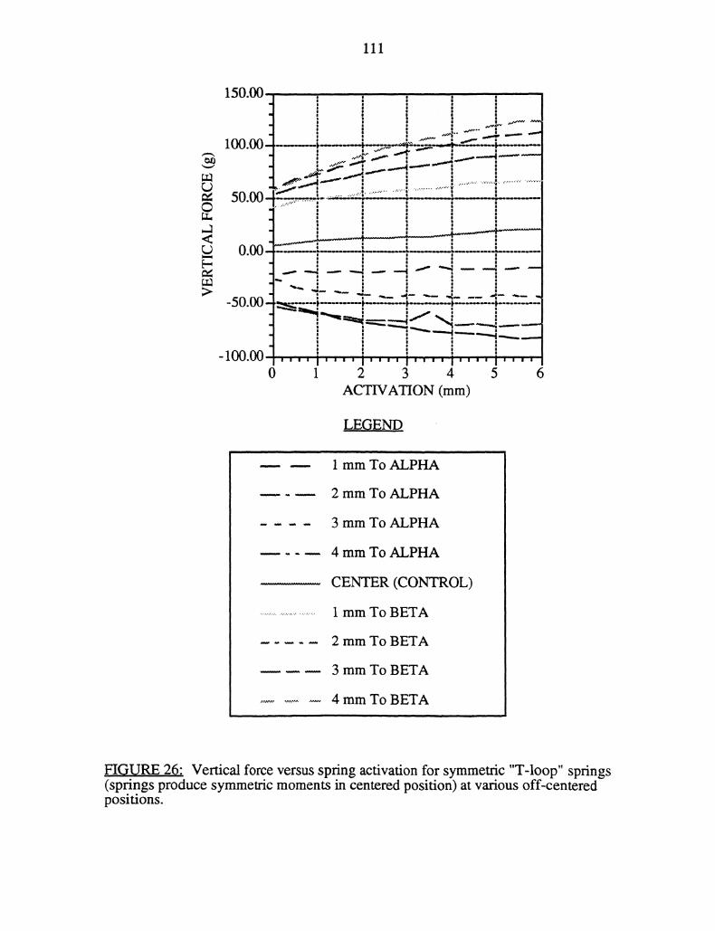
111
E-
>-50.00
100.00
150.00 7 e|l
|
100.00- -.-----:...;=--’-’-,,.=---t-=--- -----"..
,s":.. .............................-w’".’" ..........................
.-.. ._4 ..__..i * "-..---
"-.-.!_._-.i ’, [;
--"-I’--’"i’.....-.
0 1 2 3 4 5ACTIVATION (ram)
L.EGEND
1 mm To ALPHA
2 mm To ALPHA
3 mm To ALPHA
4 mm To ALPHA
CENTER (CONTROL)
1 mm To BETA
2 mm To BETA
3 mm To BETA
4 mm To BETA
FIGURE ,26: Vertical force versus spring activation for symmetric "T-loop" springs(springs produce symmetric moments in centered position) at various off-centeredpositions.
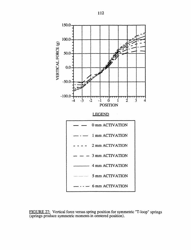
112
-4 -3 -2 -1 0 1 2 3 4POSITION
LEGEND
0 mm ACTIVATION
1 mm ACTIVATION
2 mm ACTIVATION
3 mm ACTIVATION
4 mm ACTIVATION
5 mm ACTIVATION
6 mm ACTIVATION
FIGURE 27" Vertical force versus spring position for symmetric "T-loop" springs(springs produce symmetric moments in centered position).
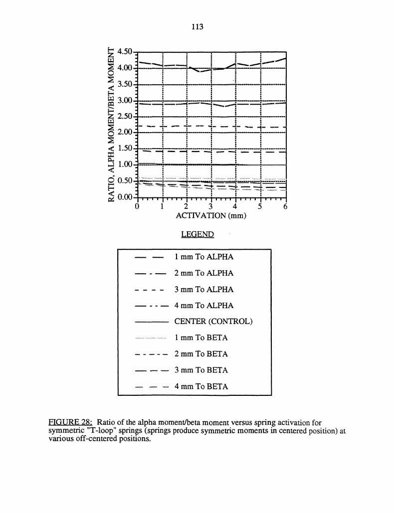
113
4.50
4.00
3.50"3.00
2.50’
2.00
1.00-<do.5o ..M
"’0.00
0 1 2 3 4 5 6ACTIVATION (mm)
LEGEND
1 mm To ALPHA
2 mm To ALPHA
3 mm To ALPHA
4 mm To ALPHA
CENTER (CONTROL)
1 mm To BETA
2 mm To BETA
3 mm To BETA
4 mm To BETA
FIGURE 28- Ratio of the alpha moment/beta moment versus spring activation forsymmetric "T-loop" springs (springs produce symmetric moments in centered position) atvarious off-centered positions.
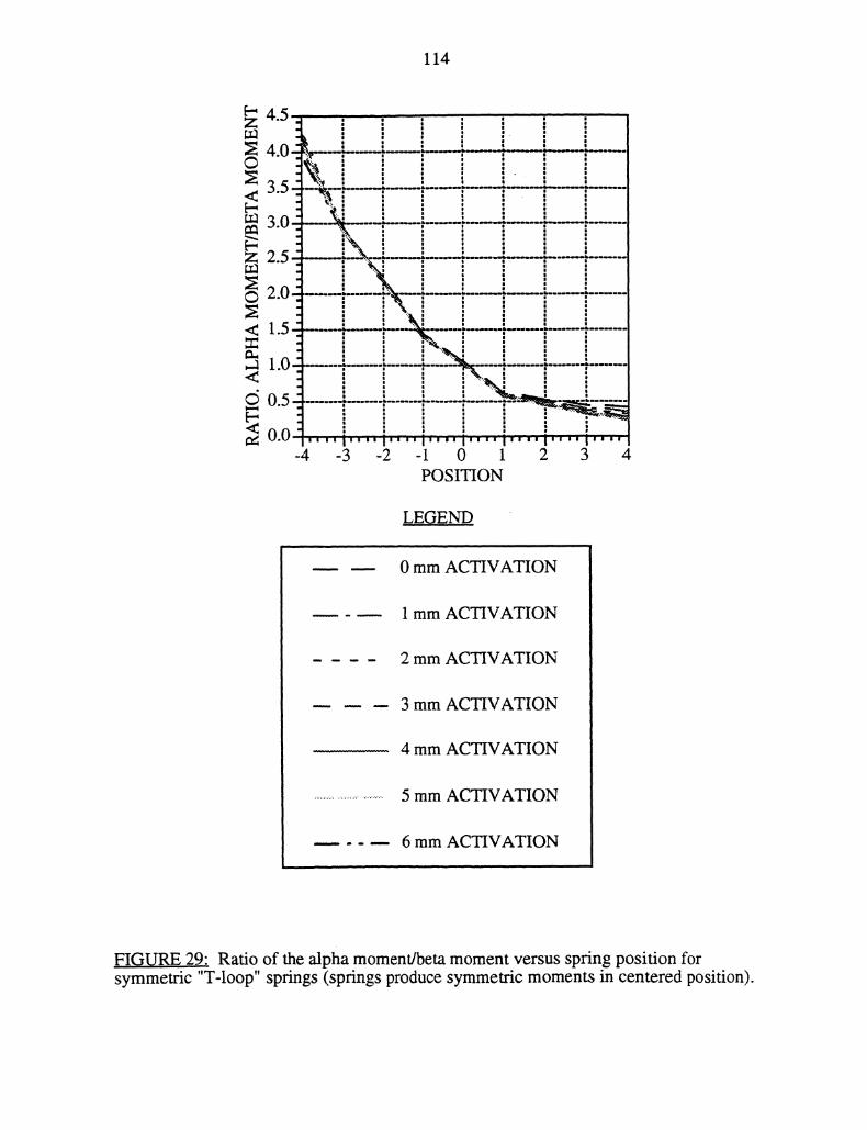
114
< 1.5"
1.0<
0.5
0.0-4
%.
"..
."’.
"’i.
’..""’’""’ i’"" i’"" i" i""1’’" I" "i" "
-3 -2 -1 0 1 2 3 4POSITION
LEG.END
0 mm ACTIVATION
1 mm ACTIVATION
2 mm ACTIVATION
3 mm ACTIVATION
4 mm ACTIVATION
5 mm ACTIVATION
6 mm ACTIVATION
FIGURE 29_’. Ratio of the alpha moment/beta moment versus spring position forsymmetric "T-loop" springs (springs produce symmetric moments in centered position).
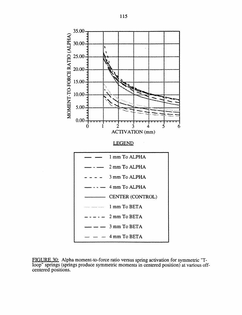
115
J30.00--u
J
5.oo , :
20.00
[ --’15.00" -.----..,.--|"-.
10.00 k..,N>-...-- .--_
-’-.
".’.:,,.5.00 ..........
,," ""o-o--.-
"V" -1" -’"--"I "-",; ;.-]I
40.00-"| ""’’
0 1 2 3 4 5 6ACTIVATION (ram)
LEGEND
1 mm To ALPHA
2 mm To ALPHA
3 mm To ALPHA
4 mm To ALPHA
CENTER (CONTROL)
1 mm To BETA
2 mm To BETA
3 mm To BETA
4 mm To BETA
F!QURE,.30", Alpha moment-to-force ratio versus spring activation for symmetric "T-loop" springs (springs produce symmetric moments in centered position) at various off-centered positions.
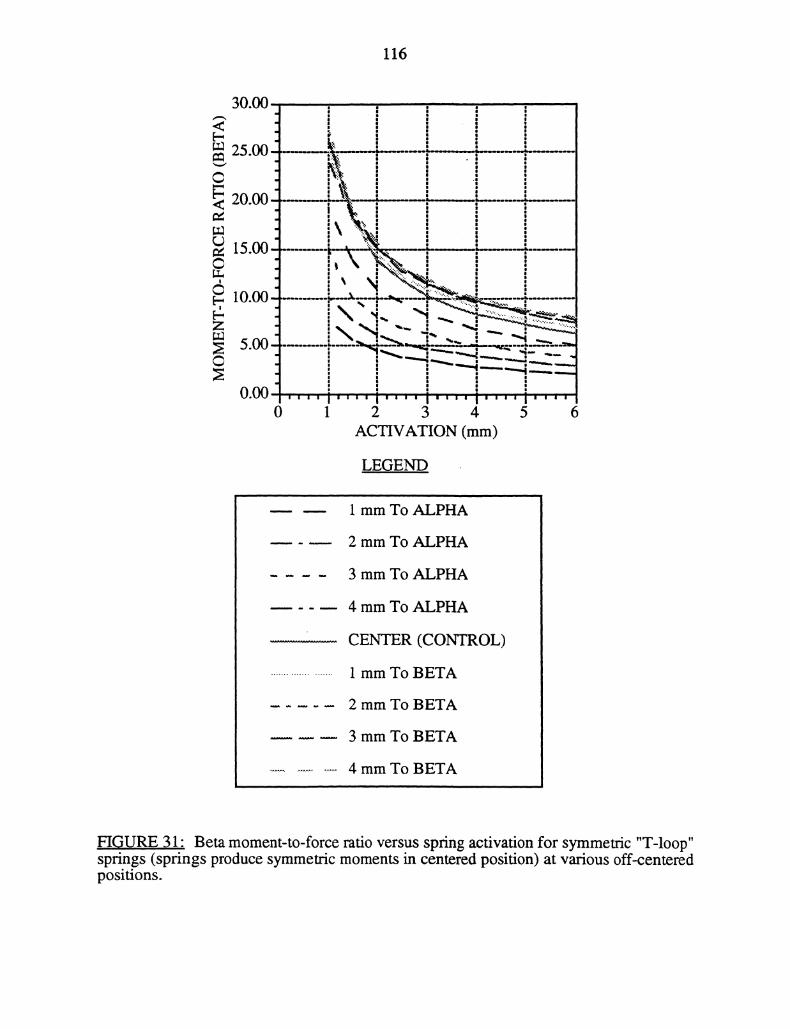
116
30.00
.25.00 ’
,,:.:"
z.uou’’."
15.00...’."’._
_,,..--,,-_"-.-...-
i,. ’" .d "’ ..............5oo .
III
0 1 2 3 4 5 6ACTIVATION (mm)
LEGEND
1 mm To ALPHA
2 mm To ALPHA
3 mm To ALPHA
4 mm To ALPHA
CENTER (CONTROL)
1 mm To BETA
2 mm To BETA
3 mm To BETA
4 mm To BETA
,FIGU,RE 31" Beta moment-to-force ratio versus spring activation for symmetric "T-loop"springs (springs produce symmetric moments in centered position) at various off-centeredpositions.
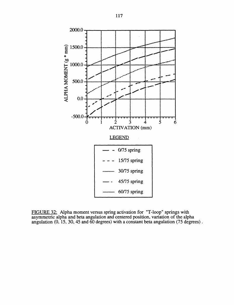
117
2000.0
1500.0-
1000.0Z
500.0
0.0"
-500.0
LEGEND
0/75spring
15/75 spring
30/75 spring
45/75 spring
60/75 spring
FIGURE 32: Alpha moment versus spring activation for "T-loop" springs withasymmetric alpha and beta angulation and centered position, variation of the alphaangulation (0, 15, 30, 45 and 60 degrees) with a constant beta angulation (75 degrees).
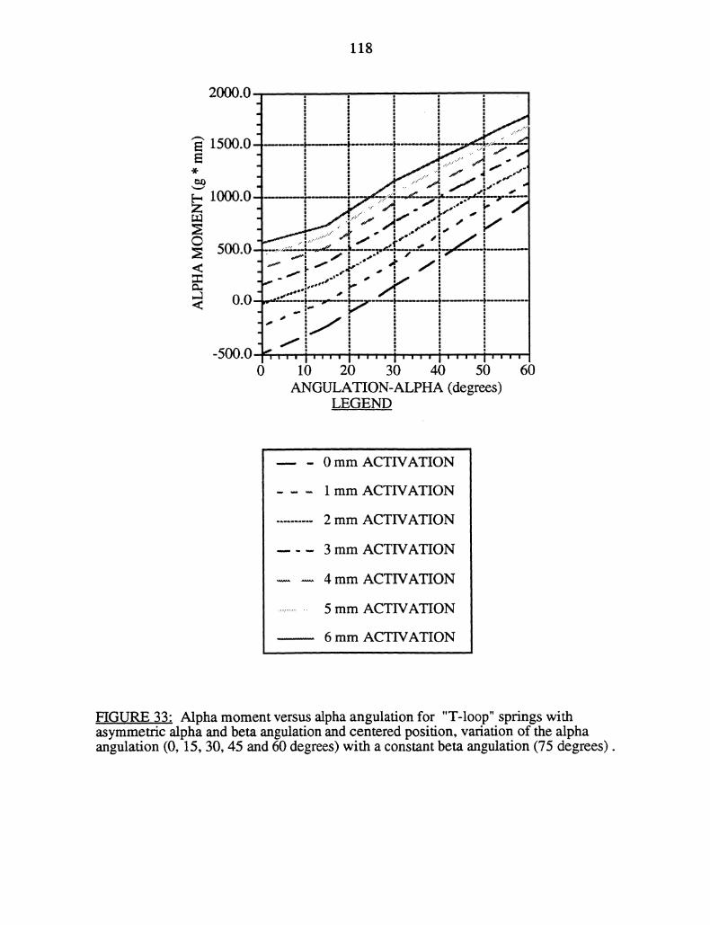
118
..;..’-"
1500.0 ------, -------------.-..--";----,
_,,,’.i ,"_, i_.’-
1 )lil I1 -.,:.-.z_.--._.r:.!--.-..--.,/ / =.,
=cu’i..W.U
."i’"
_..v" "!.’ /i
.r .o:"" }’"
/ #
I,,,-
-ouu.u I’"’’ I’"’’ I’’’1 ’’ I"’"’’0 10 20 30 40 50 60
ANGULATION-ALPHA (degrees)LEGEND
0 mm ACTIVATION
1 mm ACTIVATION
2 mm ACTIVATION
3 mm ACTIVATION
4 mm ACTWATION
5 mm ACTIVATION
6 mm ACTIVATION
FIGURE 33" Alpha moment versus alpha angulation for "T-loop" springs withasymmetric alpha and beta angulation and centered position, variation of the alphaangulation (0, 15, 30, 45 and 60 degrees) with a constant beta angulation (75 degrees).
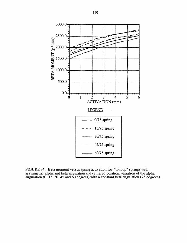
119
3000.0
2500.0
2000.0
1500.0
LEGEND
0/75 spring
15/75 spring
30/75 spring
45/75 spring
60/75 spring
FIGURE 34" Beta moment versus spring activation for "T-loop" springs withasymmetric alpha and beta angulation and centered position, variation of the alphaangulation (0, 15, 30, 45 and 60 degrees) with a constant beta angulation (75 degrees).
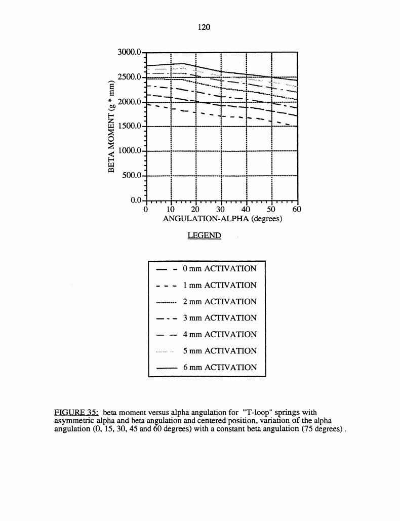
120
25.0 "" " -- ’-
." --! ---- ilS O----.-
10
5 0
o.o ,,,,i i,.,.i,,,,i,.,,i0 10 20 30 40 50 60
GULATION-PHA (degrees)
LE.GEND
0 mm ACTIVATION
1 mm ACTIVATION
2 mm ACTIVATION
3 mm ACTIVATION
4 mm ACTIVATION
5 mm ACTIVATION
6 mm ACTIVATION
FIGURE 35" beta moment versus alpha angulation for "T-loop" springs withasymmetric alpha and beta angulation and centered position, variation of the alphaangulafion (0, 15, 30, 45 and 60 degrees) with a constant beta angulation (75 degrees).
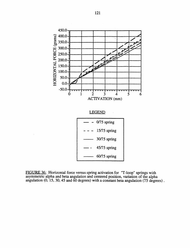
121
450.0
400.0 .----.---,-
350.0
300.0
250.0 ’
200.0 "-
150.0
100.0
500
0.0
-50 00 1 2 3 4 5 6
ACTIVATION (mm)
LEGEND
0/75spring
15/75 spring
30/75 spring
45/75 spring
60/75 spring
FIGURE 36" Horizontal force versus spring activation for "T-loop" springs withasymmetric alpha and beta angulation and centered position, variation of the alphaangulation (0, 15, 30, 45 and 60 degrees) with a constant beta angulation (75 degrees).
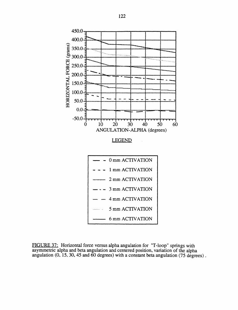
122
250.0
200.0
150.0
1oo.o
50.0
0.0"
-50.00 10 20 30 40 50 60
ANGULATION-ALPHA (degrees)
LEGEND
0 mm ACTIVATION
1 mm ACTIVATION
2 mm ACTIVATION
3 mm ACTIVATION
4 mm ACTIVATION
5 mm ACTIVATION
6 mm ACTIVATION
FIGURE 37" Horizontal force versus alpha angulation for "T-loop" springs withasymmetric alpha and beta angulation and centered position, variation of the alphaangulation (0, 15, 30, 45 and 60 degrees) with a constant beta angulation (75 degrees).
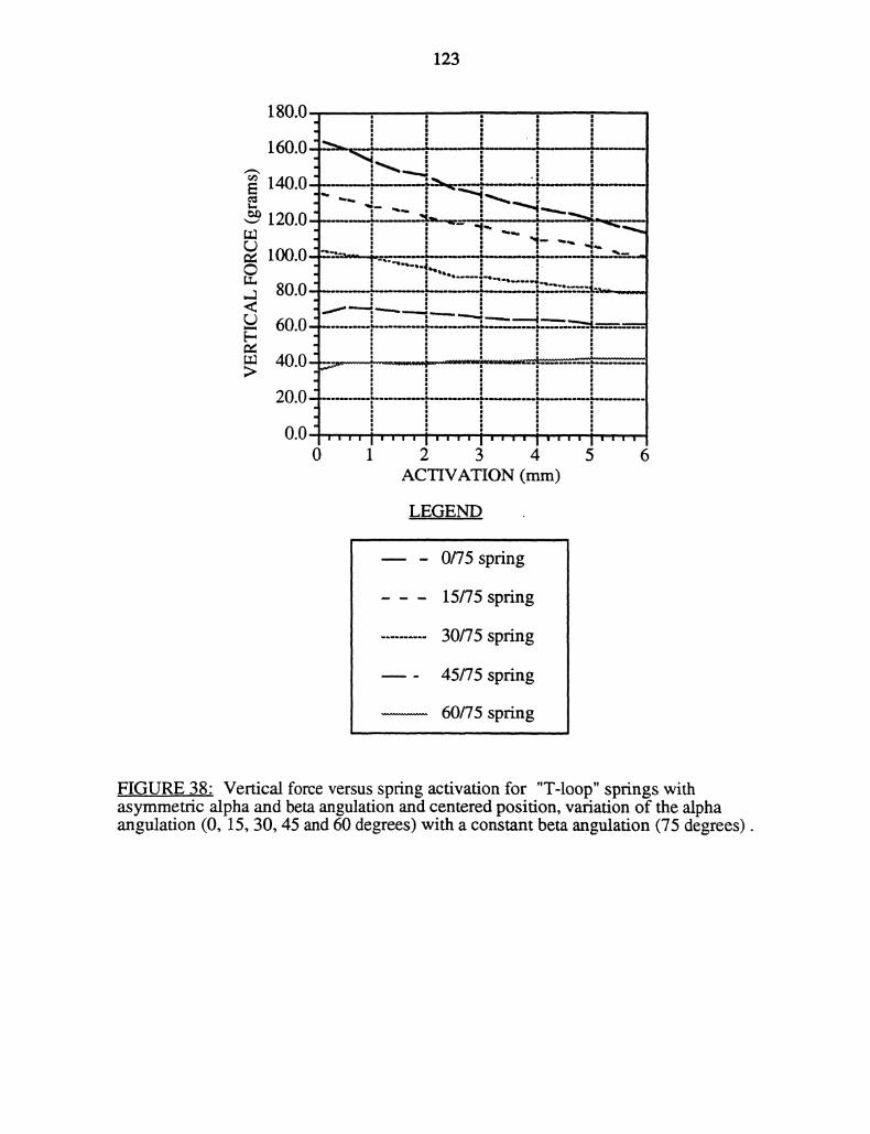
123
180.0.160.0
140.0.120.0
100.0-
80.0
60.0
40.0
20.0-:0.0"
0
/
Illltllllllllillltlillllllilillllllll
i..,,1 2 3 4 5 6
ACVATION (ram)
LEGEND
0/75 spring
15/75 spring
30/75 spring
45/75 spring
60/75 spring
FIGURE 38" Vertical force versus spring activation for "T-loop" springs withasymmetric alpha and beta angulation and centered position, variation of the alphaangulation (0, 15, 30, 45 and 60 degrees) with a constant beta angulation (75 degrees).
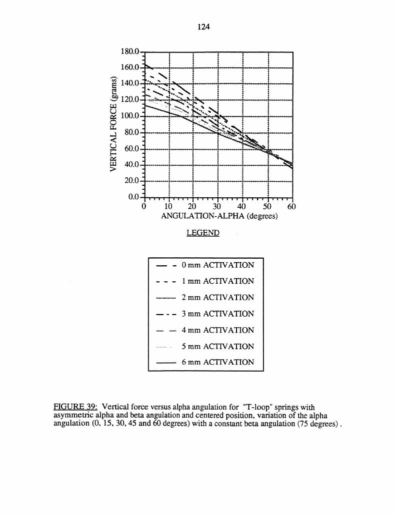
124
180.0 q
160.0le
.,-,.uu’""." "-’, m,
’ ’*i.
120.0 ..............,-, _---,
.......u .40.0
20.0
0.0 ,-,,, ,..,,, ,, , ,,,.,, ,,,,0 10 20 30 40 50 60
GULAON-PHA (degrees)
LEGEND
0 mm ACTIVATION
1 mm ACTIVATION
2 mm ACTIVATION
3 mm ACTIVATION
4 mm ACTIVATION
5 mm ACTIVATION
6 mm ACTIVATION
FIGURE 39: Vertical force versus alpha angulation for "T-loop" springs withasymmetric alpha and beta angulation and centered position, variation of the alphaangulation (0, 15, 30, 45 and 60 degrees) with a constant beta angulation (75 degrees).
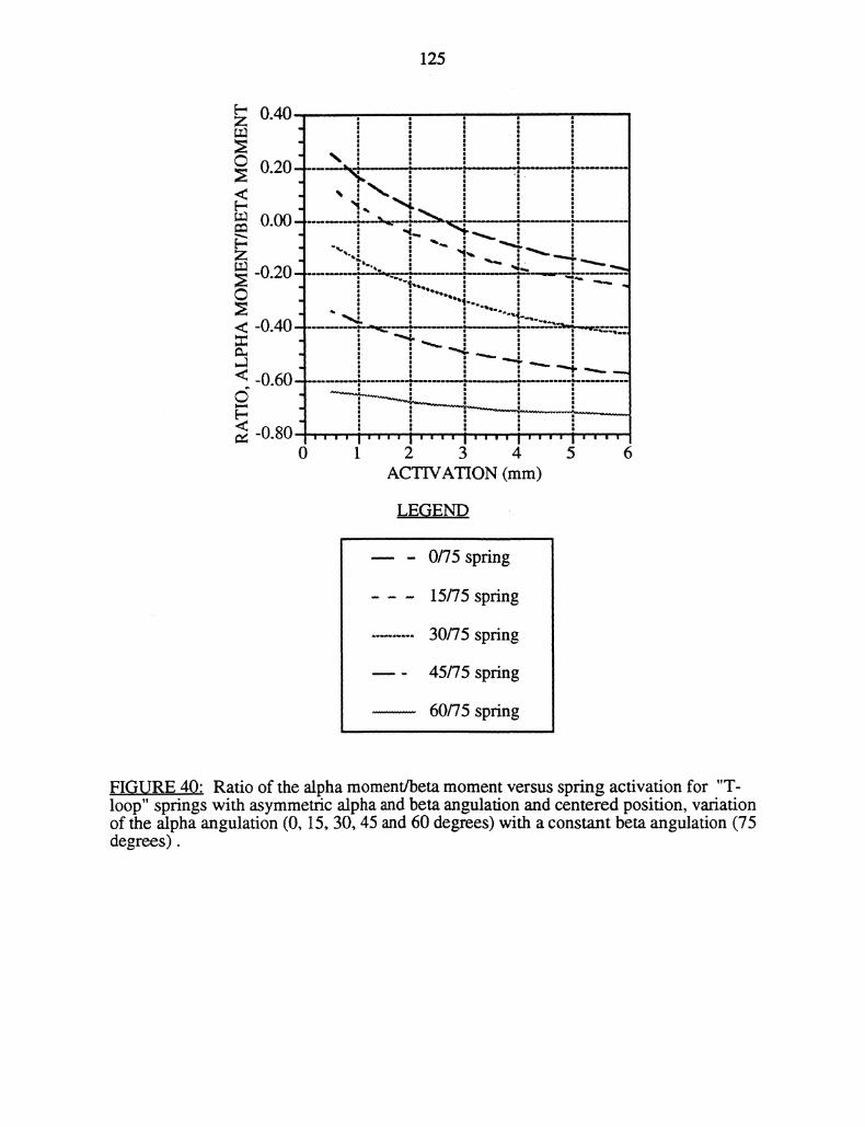
125
-0.60
-0.80
,’- ’ ,"
i’’’"i’’’"i’’’’ ’I’’"’1 2 3 4 5 6
ACTIVATION (mm)
LEGEND
0/75 spring
15/75 spring
30/75 spring
45/75 spring
60/75 spring
FIGURE 40: Ratio of the alpha moment/beta moment versus spring activation for "T-loop" springs with asymmetric alpha and beta angulation and centered position, variationof the alpha angulation (0, 15, 30, 45 and 60 degrees) with a constant beta angulation (75degrees).
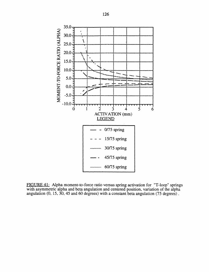
126
35.0 ,
30.0"
25.0"-20.0
Ju’."
UUIR.R
.R
0.0
-.Ju
-1007
0/75 spring
15/75 spring
30/75 spring
45/75 spring
60/75 spring
FIGURE 41- Alpha moment-to-force ratio versus spring activation for "T-loop" springswith asymmetric alpha and beta angulation and centered position, variation of the alphaangulation (0, 15, 30, 45 and 60 degrees) with a constant beta angulation (75 degrees).
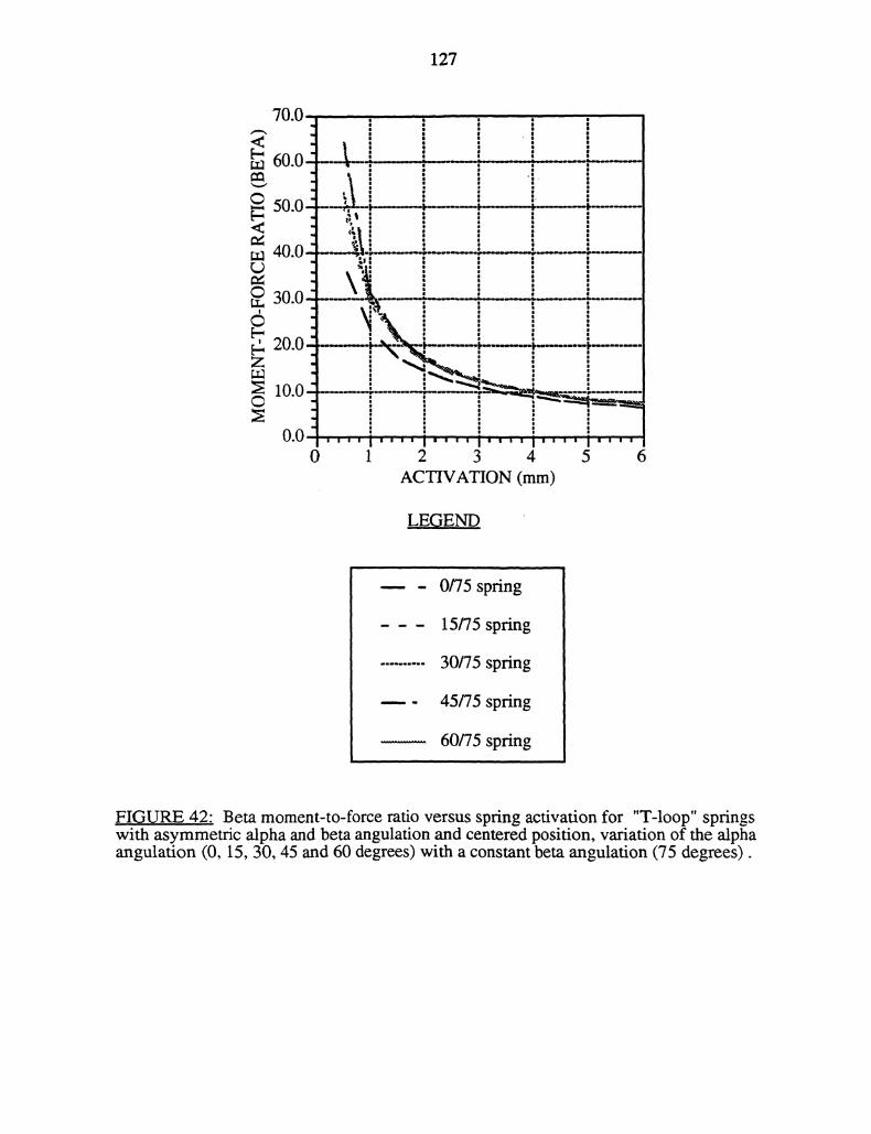
127
70.0
60.050.0
40.0
30.0
20.0
10.0
0 1 2 3 4 5 6ACTIVATION (mm)
LEGEND.
0/75 spring
15/75 spring
30/75 spring
45/75 spring
60/75 spring
FIGU..RE 42: Beta moment-to-force ratio versus spring activation for "T-loop" springswith asymmetric alpha and beta angulation and centered position, variation of the alphaangulation (0, 15, 30, 45 and 60 degrees) with a constant beta angulation (75 degrees).
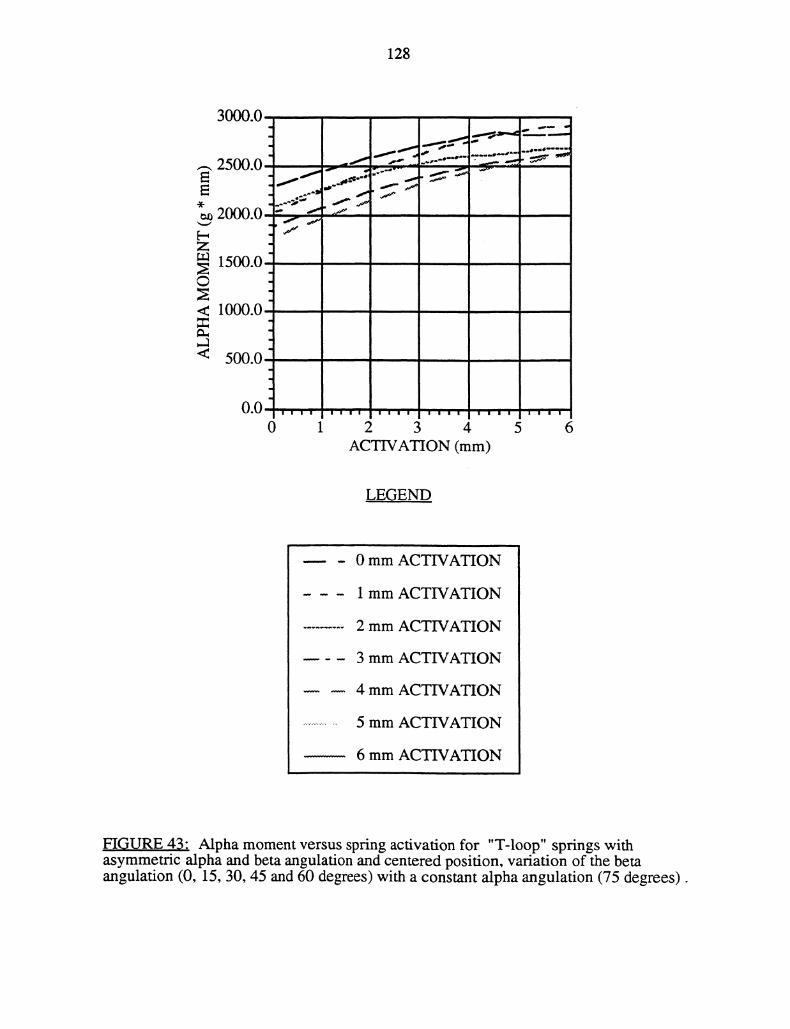
128
3000.0
0 1 2 3 4 5 6ACTIVATION (mm)
LEGEND
0 mm ACTIVATION
1 mm ACTIVATION
2 mm ACTIVATION
3 mm ACTIVATION
4 mm ACTIVATION
5 mm ACTIVATION
6 mm ACTIVATION
FIGURE 43" Alpha moment versus spring activation for "T-loop" springs withasymmetric alpha and beta angulation and centered position, variation of the betaangulation (0, 15, 30, 45 and 60 degrees) with a constant alpha angulation (75 degrees).
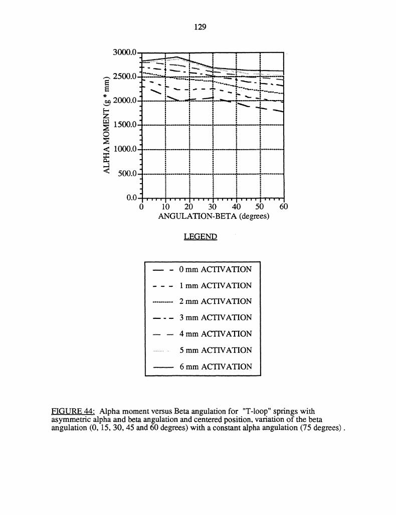
129
-. .;, --"r..-,.
1 %+
2.0
m 150’
< 10
< 5.0 !
0.0 ’"’I’’’’1’’’’1’’"10 10 20 30 40 50 60
GULAON-BETA (degrees)
LEGEND
0 mm ACTIVATION
1 mm ACTIVATION
2 mm ACTIVATION
3 mm ACTIVATION
4 mm ACTWATION
5 mm ACTWATION
6 mm ACTWATION
HGURE 44: Alpha moment versus Beta angulation for "T-loop" springs withasymmetric alpha and beta angulation and centered position, variation of the betaangulation (0, 15, 30, 45 and 60 degrees) with a constant alpha angulation (75 degrees).
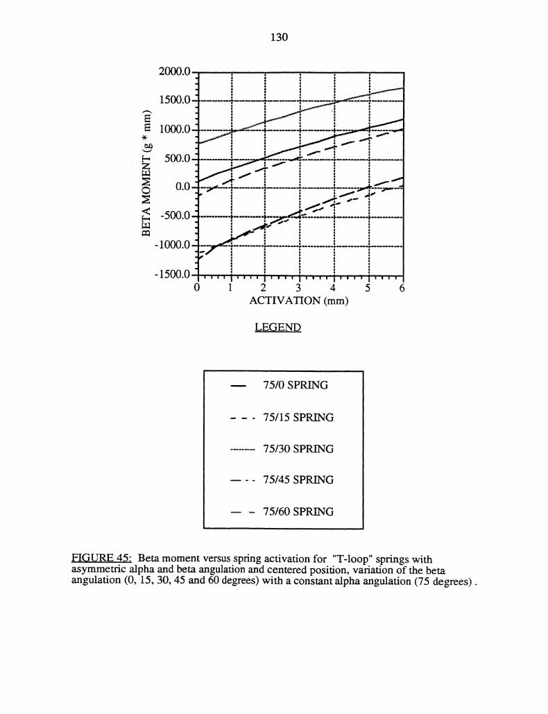
130
Z
2000.0
1500.0
1000.0
ACTIVATION (mm)
LE(END
75/0 SPRING
75/15 SPRING
75/30 SPRING
75/45 SPRING
75/60SPRING
FIGURE 45" Beta moment versus spring activation for "T-loop" springs withasymmetric alpha and beta angulation and centered position, variation of the betaangulation (0, 15, 30, 45 and 60 degrees) with a constant alpha angulation (75 degrees).
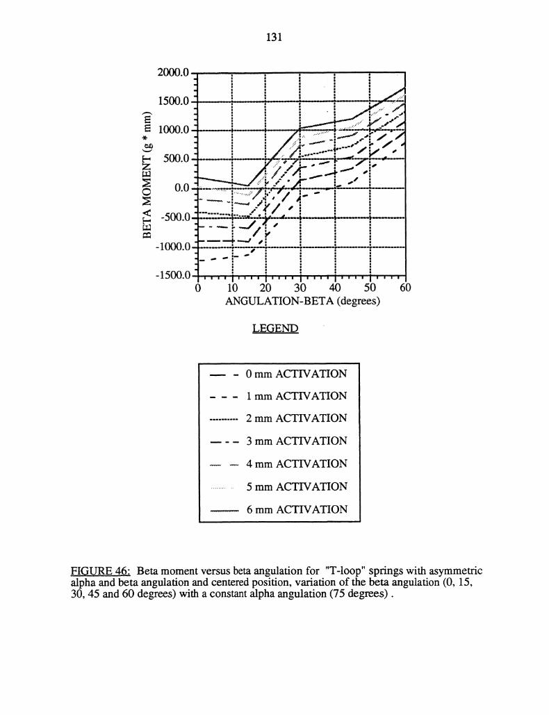
131
LEGEND
0 mm ACTIVATION
1 mm ACTIVATION
2 mm ACTIVATION
3 mm ACTIVATION
4 mm ACTIVATION
5 mm ACTIVATION
6 mm ACTIVATION
FIGURE 4.6" Beta moment versus beta angulation for "T-loop" springs with asymmetricalpha and beta angulation and centered position, variation of the beta angulation (0, 15,30, 45 and 60 degrees) with a constant alpha angulation (75 degrees).
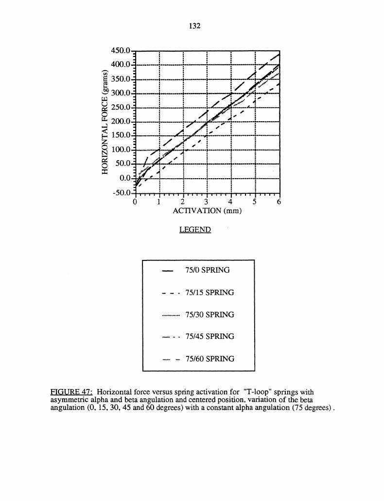
132
450.0
350 0 ---250 0 #----
o -M---------- "1 --o]-50. ’" ’t""’ I’"’’ i’""’0 1 2 3 4 5 6
ACVATION (ram)
L.EGE.ND
75/0 SPRING
75/15 SPRING
75/30 SPRING
75/45 SPRING
75/60 SPRING
FIGURE 47- Horizontal force versus spring activation for "T-loop" springs withasymmetric alpha and beta angulation and centered position, variation of the betaangulation (0, 15, 30, 45 and 60 degrees) with a constant alpha angulation (75 degrees).
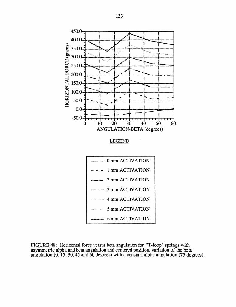
133
’,---F _--i’- . "
!----- 4-- -’’---:
I,,,, I,,,, I,,,, I,,,, ii,,,0 10 20 30 40 50 60
ANGULATION-BETA (degrees)
LEG.E.NI...
0 mm ACTIVATION
1 mm ACTIVATION
2 mm ACTIVATION
3 mm ACTIVATION
4 mm ACTIVATION
5 mm ACTIVATION
6 mm ACTIVATION
FIGURE 48" Horizontal force versus beta angulation for "T-loop" springs withasymmetric alpha and beta angulation and centered position, variation of the betaangulation (0, 15, 30, 45 and 60 degrees) with a constant alpha angulation (75 degrees).
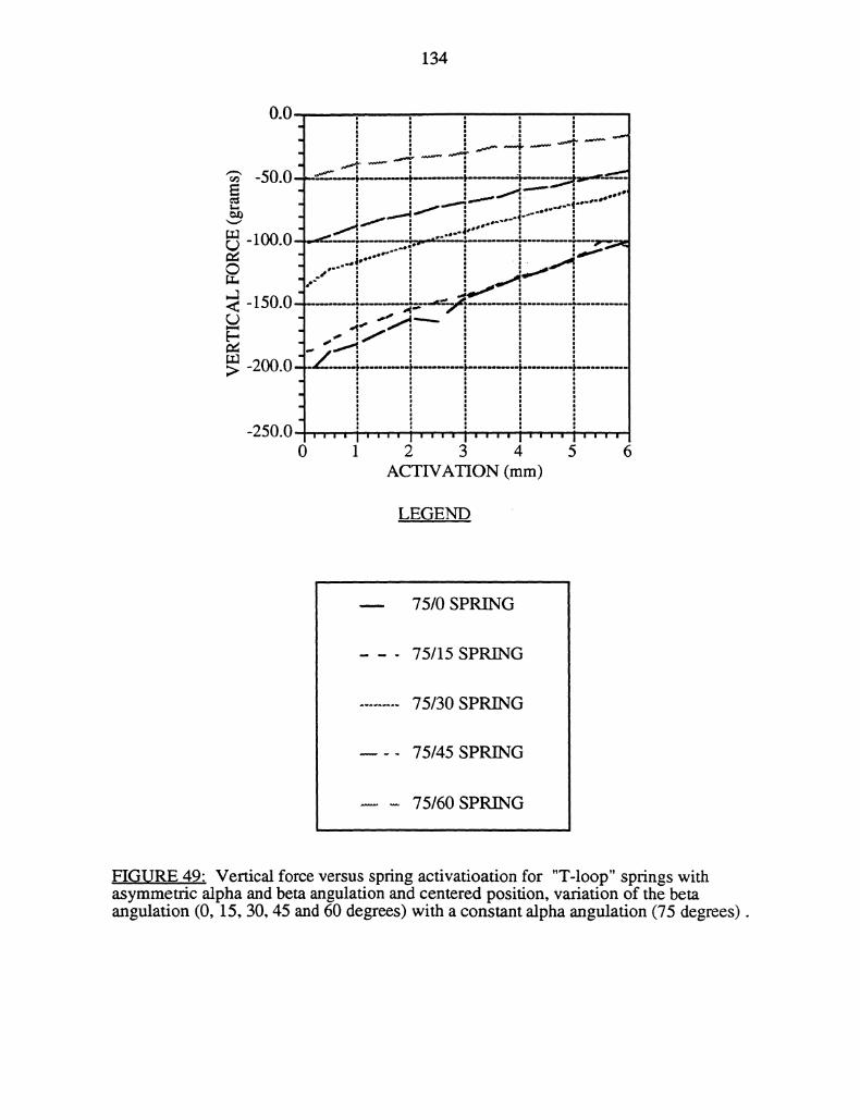
134
-50.0--"- --- P.-----t-------;P----.j,..,-------.
,M
Ill".O -,,..,__ __......-:..;,,;.,,---.:, T_.___I-I .....J ..|
IJUuICA.A ....
-200.0
250 00 1 2 3 4 5 6
ACTIVATION (mm)
LEGEND
75/0 SPRING
75/15 SPRING
75/30 SPRING
75/45 SPRING
75/60 SPRING
FIGURE 49: Vertical force versus spring activatioation for "T-loop" springs withasymmetric alpha and beta angulation and centered position, variation of the betaangulation (0, 15, 30, 45 and 60 degrees) with a constant alpha angulation (75 degrees).
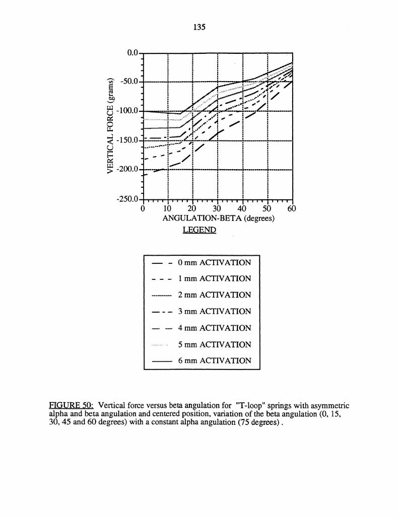
135
.,0
..."-" ,’
-.U.U
.,............... _., .#’ ’:,.""_.7.-’../" .,; ."
....."" i_.,.-."- ,,I..:.’"Innn_ __...,_...-"-:"_.,z_
J I.r " 10-2:--: !....,,,,,-,..=150
i
-200.0 -.4:
250 0 ,’’"’ i’’’’ i’’’’ I’’"’ I"’’"1’’’’0 10 20 30 40 50 60
ANGULATION-BETA (degrees)LEGEND
0 mm ACTIVATION
1 mm ACTIVATION
2 mm ACTIVATION
3 mm ACTIVATION
4 mm ACTIVATION
5 mm ACTIVATION
6 mm ACTIVATION
FIG.URE 5,.0: Vertical force versus beta angulation for "T-loop" springs with asymmetricalpha and beta angulation and centered position, variation of the beta angulafion (0, 15,30, 45 and 60 degrees) with a constant alpha angulation (75 degrees).
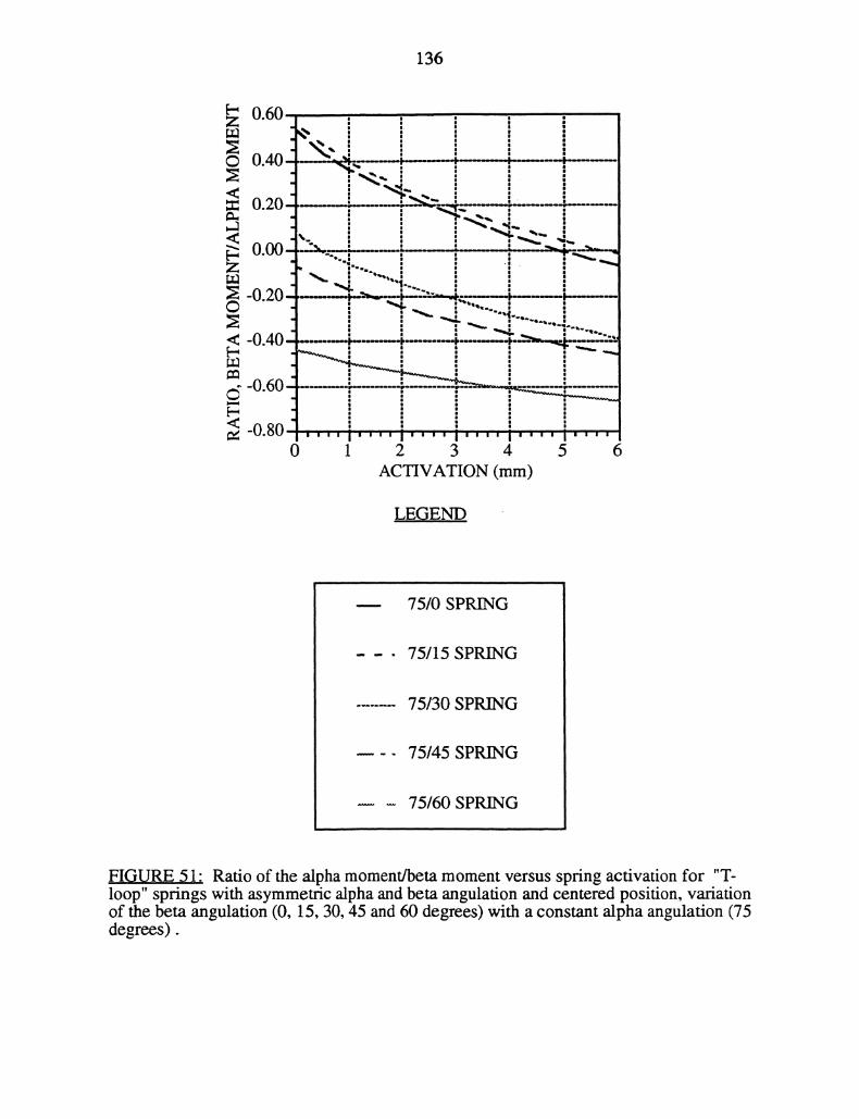
136
0.60
0.20 ’-
vvvn." ._IIIIIII.I
_n.n. "’--
-0.40 .....
-0.80 I’’" I’’’’ I,,,’ I.’’’0 1 2 3 4 5 6
ACVATION (mm)
LEGEND
75/0 SPRING
75/15 SPRING
75/30 SPRING
75/45 SPRING
75/60 SPRING
FIGURE 51" Ratio of the alpha moment/beta moment versus spring activation for "T-loop" springs with asymmetric alpha and beta angulation and centered position, variationof the beta angulation (0, 15, 30, 45 and 60 degrees) with a constant alpha angulation (75degrees).
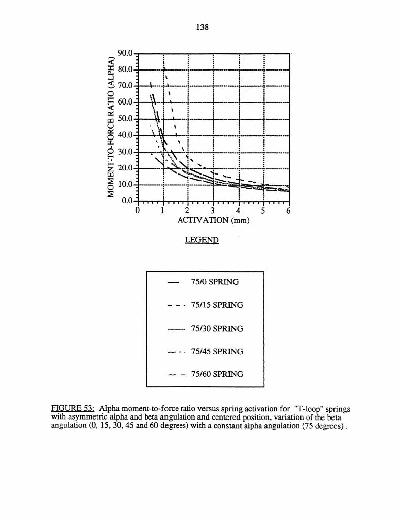
138
90.0
80.0-’ 2
70.0-’-i
60.0 --:-- a .: :
50.0i-1
,NNIIIllil40.0 "
.;-.-.30.0
N \i ",20.0 ...............---.--, "
10.0 .-,- .-_:_.--..--,
II |I
0 1 2 3 4 5 6ACTIVATION (ram)
LEGEND
75/0 SPRING
75/15 SPRING
75/30 SPRING
75/45 SPRING
75/60SPRING
FIGURE 53" Alpha moment-to-force ratio versus spring activation for "T-loop" springswith asymmetric alpha and beta angulafion and centered position, variation of the betaangulation (0, 15, 30, 45 and 60 degrees) with a constant alpha angulation (75 degrees).
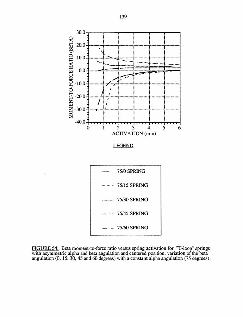
139
[-Z
(C)
30 0 ,,
20 0 ,,- ,,- ,,- ;
10.0 i--’-.’ i- i- p"," - ’- l -4
_...... _dT
#’
-20.0 I,--,,. F
-3o.o ", U - . -40 0 "’"" i’’’"l""’’! ’’’ I’’""’0 1 2 3 4 5 6
ACTIVATION (mm)
LEGEND
75/0 SPRING
75/15 SPRING
75/30 SPRING
75/45 SPRING
75/60 SPRING
FIGURE 54: Beta moment-to-force ratio versus spring activation for "T-loop" springswith asymmetric alpha and beta angulation and centered position, variation of the betaangulation (0, 15, 30, 45 and 60 degrees) with a constant alpha angulation (75 degrees).