8/4/2019 Flash en Flex Ray ElektronikAutomotive 200711 Press Article En
http://slidepdf.com/reader/full/flash-en-flex-ray-elektronikautomotive-200711-press-article-en 1/15
Technical Article
Optimal Flashing by FlexRay 1/15
Optimal Flashing via FlexRay
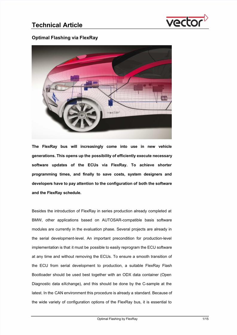
The FlexRay bus will increasingly come into use in new vehicle
generations. This opens up the possibility of efficiently execute necessary
software updates of the ECUs via FlexRay. To achieve shorter
programming times, and finally to save costs, system designers and
developers have to pay attention to the configuration of both the software
and the FlexRay schedule.
Besides the introduction of FlexRay in series production already completed at
BMW, other applications based on AUTOSAR-compatible basis software
modules are currently in the evaluation phase. Several projects are already in
the serial development-level. An important precondition for production-level
implementation is that it must be possible to easily reprogram the ECU software
at any time and without removing the ECUs. To ensure a smooth transition of
the ECU from serial development to production, a suitable FlexRay Flash
Bootloader should be used best together with an ODX data container (Open
Diagnostic data eXchange), and this should be done by the C-sample at the
latest. In the CAN environment this procedure is already a standard. Because of
the wide variety of configuration options of the FlexRay bus, it is essential to

8/4/2019 Flash en Flex Ray ElektronikAutomotive 200711 Press Article En
http://slidepdf.com/reader/full/flash-en-flex-ray-elektronikautomotive-200711-press-article-en 2/15
Technical Article
Optimal Flashing by FlexRay 2/15
conduct a detailed analysis to determine which configurations lead to the best
performance of the FlexRay flash bootloader.
Fundamentals of flashing
“Flashing” refers to the process of transferring software code and data to the
ECU’s flash memory (also called Flash-EEPROM). Unlike EEPROM memory,
flash memory can only be erased or written block-by-block. During
development, for example, data transfer might be performed via a debugger,
which requires removal of the ECU. In contrast to this, in production and in the
service area a flash tool initiates the flash process via a diagnostic protocol
such as UDS (Unified Diagnostic Services), which is executed on the
microcontroller side by the FlexRay Flash Bootloader without dismantling the
ECU.
In flashing, requirements of both the OEM and the ECU supplier must be
considered. The key requirements here are short programming times, low
memory requirement and security against manipulation. The FlexRay Flash
Bootloader is saved in the flash memory of the embedded CPU as an
independent, non-erasable application next to the rewritable application. Either
the application or the FlexRay flash bootloader is executed. The Vector FlexRay
Flash Bootloader [1] consists of configurable embedded software modules that
are subdivided into the following functional blocks according to Figure 1:
• Flash driver
• Bootloader
• FlexRay stack
8/4/2019 Flash en Flex Ray ElektronikAutomotive 200711 Press Article En
http://slidepdf.com/reader/full/flash-en-flex-ray-elektronikautomotive-200711-press-article-en 3/15
Technical Article
Optimal Flashing by FlexRay 3/15
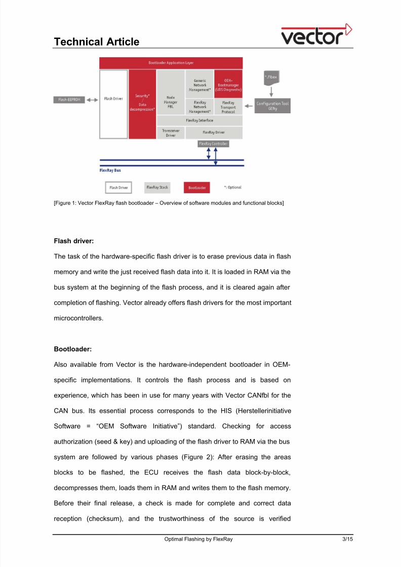
[Figure 1: Vector FlexRay flash bootloader – Overview of software modules and functional blocks]
Flash driver:
The task of the hardware-specific flash driver is to erase previous data in flash
memory and write the just received flash data into it. It is loaded in RAM via the
bus system at the beginning of the flash process, and it is cleared again after
completion of flashing. Vector already offers flash drivers for the most important
microcontrollers.
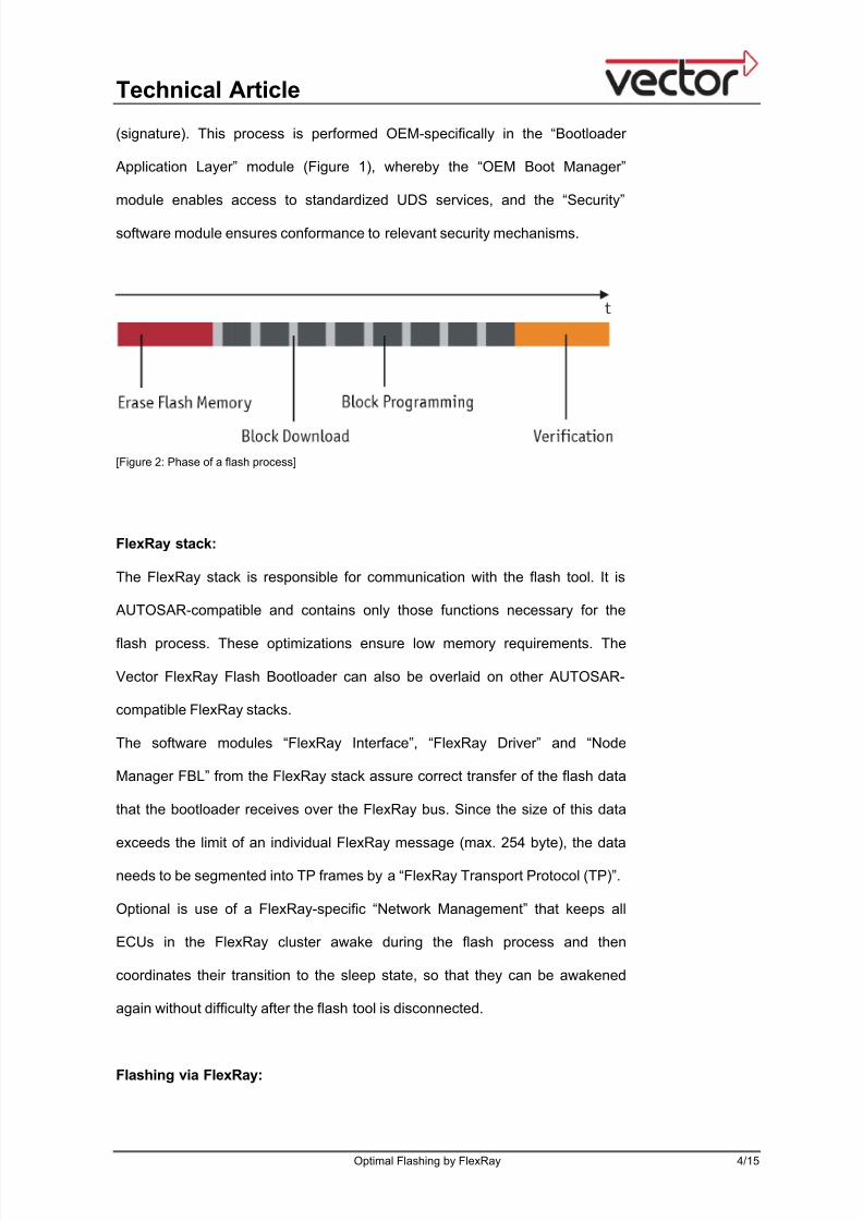
Bootloader:
Also available from Vector is the hardware-independent bootloader in OEM-
specific implementations. It controls the flash process and is based on
experience, which has been in use for many years with Vector CANfbl for the
CAN bus. Its essential process corresponds to the HIS (Herstellerinitiative
Software = “OEM Software Initiative”) standard. Checking for access
authorization (seed & key) and uploading of the flash driver to RAM via the bus
system are followed by various phases (Figure 2): After erasing the areas
blocks to be flashed, the ECU receives the flash data block-by-block,
decompresses them, loads them in RAM and writes them to the flash memory.
Before their final release, a check is made for complete and correct data
reception (checksum), and the trustworthiness of the source is verified
8/4/2019 Flash en Flex Ray ElektronikAutomotive 200711 Press Article En
http://slidepdf.com/reader/full/flash-en-flex-ray-elektronikautomotive-200711-press-article-en 4/15
Technical Article
Optimal Flashing by FlexRay 4/15
(signature). This process is performed OEM-specifically in the “Bootloader
Application Layer” module (Figure 1), whereby the “OEM Boot Manager”
module enables access to standardized UDS services, and the “Security”
software module ensures conformance to relevant security mechanisms.
[Figure 2: Phase of a flash process]
FlexRay stack:
The FlexRay stack is responsible for communication with the flash tool. It is
AUTOSAR-compatible and contains only those functions necessary for the
flash process. These optimizations ensure low memory requirements. The
Vector FlexRay Flash Bootloader can also be overlaid on other AUTOSAR-
compatible FlexRay stacks.
The software modules “FlexRay Interface”, “FlexRay Driver” and “Node
Manager FBL” from the FlexRay stack assure correct transfer of the flash data
that the bootloader receives over the FlexRay bus. Since the size of this data
exceeds the limit of an individual FlexRay message (max. 254 byte), the data
needs to be segmented into TP frames by a “FlexRay Transport Protocol (TP)”.
Optional is use of a FlexRay-specific “Network Management” that keeps all
ECUs in the FlexRay cluster awake during the flash process and then
coordinates their transition to the sleep state, so that they can be awakened
again without difficulty after the flash tool is disconnected.
Flashing via FlexRay:
8/4/2019 Flash en Flex Ray ElektronikAutomotive 200711 Press Article En
http://slidepdf.com/reader/full/flash-en-flex-ray-elektronikautomotive-200711-press-article-en 5/15
Technical Article
Optimal Flashing by FlexRay 5/15
Although FlexRay offers a high data rate of up to 10 MBit/sec, if the software
and the FlexRay schedule configurations are poorly coordinated, this leads to
poor flash performance. Therefore, the bootloader, transport protocol and
FlexRay schedule need to be configured carefully.
FlexRay Schedule:
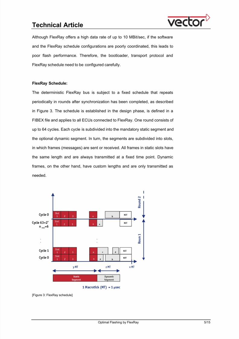
The deterministic FlexRay bus is subject to a fixed schedule that repeats
periodically in rounds after synchronization has been completed, as described
in Figure 3. The schedule is established in the design phase, is defined in a
FIBEX file and applies to all ECUs connected to FlexRay. One round consists of
up to 64 cycles. Each cycle is subdivided into the mandatory static segment and
the optional dynamic segment. In turn, the segments are subdivided into slots,
in which frames (messages) are sent or received. All frames in static slots have
the same length and are always transmitted at a fixed time point. Dynamic
frames, on the other hand, have custom lengths and are only transmitted as
needed.
[Figure 3: FlexRay schedule]
8/4/2019 Flash en Flex Ray ElektronikAutomotive 200711 Press Article En
http://slidepdf.com/reader/full/flash-en-flex-ray-elektronikautomotive-200711-press-article-en 6/15
Technical Article
Optimal Flashing by FlexRay 6/15
Currently, none of the OEMs are changing before flashing the FlexRay
schedule, because that would require a restart of the entire FlexRay cluster.
Therefore, the flash process is performed within the framework of the normal
FlexRay schedule, using TP frames transmitted in either the static segment or
the dynamic segment. The disadvantage of transfer in the static segment is that
the frame length that is usually adapted to meet the needs of the application is
fixed here. In addition, the number of FlexRay slots remaining for flashing
purposes is limited.
In the dynamic segment too, the number of FlexRay slots that flashing can
utilize is limited by the configuration. However, the size of each sent frame is
flexible here. For example with a typical cycle length of 5 msec, given a 60 to 40
percent ratio in the division between the static and dynamic segments, a max.
of 1.9 msec (without Network Idle Time of typically 100µsec) is available to the
dynamic FlexRay slots. Various TP frames of different lengths can be reliably
transmitted in this time period, about four 254-byte TP frames or twelve 32-byte
TP frames – each including the Transport Protocol header. In these
configurations about 780 µsec remain for additional dynamic frames such as
NM frames.
Transport Protocol and download rates:
The flash tool uses the UDS diagnostic service “Request Download” to
ascertain the maximum block size of the relevant ECU and then subdivide the
data to be transmitted into individual blocks. The block size is calculated in part
based on the RAM buffer size available for programming as well as the size of
the flash memory involved, which might only be programmable in 16 byte
memory units, for example. Only then does the UDS diagnostic service
“Transfer Data” segment each block into FlexRay frames. The generated
frames are managed by a header – included in each FlexRay frame in addition
to the useful data – that is sent per the selected transport protocol. Its size

8/4/2019 Flash en Flex Ray ElektronikAutomotive 200711 Press Article En
http://slidepdf.com/reader/full/flash-en-flex-ray-elektronikautomotive-200711-press-article-en 7/15
Technical Article
Optimal Flashing by FlexRay 7/15
depends on the transport protocol and its OEM-specific implementation.
Essentially, long frames produce a favorable ratio of useful data (Payload) to
protocol header.
Figure 4 shows the basic procedure for transmission of flash data in the
“Transfer Data” service by the transport protocol. The following TP frames are
used for each block:
• The flash tool sends a First Frame (FF) via the TP to the ECU, to
establish a communication channel. This frame contains information on
the block size as well as the first useful data.
• Then the ECU responds – ideally in the next FlexRay cycle – with a
Flow Control (FC) that confirms the block size. An inefficient TP
implementation lengthens the wait time for the FC frame, which impairs
the performance of the FlexRay Flash Bootloader.
• The rest of the useful data in the relevant block is transferred by
sequentially transmitted Consecutive Frames (CF).
Depending on the configuration, the exchange of FC frames and CF frames is
repeated without additional FF until all blocks have been transmitted.
[Figure 4: Basic flow of the Transfer Data service with AUTOSAR/FlexRay TP]

8/4/2019 Flash en Flex Ray ElektronikAutomotive 200711 Press Article En
http://slidepdf.com/reader/full/flash-en-flex-ray-elektronikautomotive-200711-press-article-en 8/15
Technical Article
Optimal Flashing by FlexRay 8/15
Two TP standards are currently available: ISO/TP (ISO-15765-2) and
AUTOSAR/FlexRay TP V2.1. Furthermore, the standard ISO/FlexRay TP (ISO-
10681-2) is in preparation.
The ISO/TP is used widely in the CAN environment, and for TP messages it
specifies a length of precisely 8 bytes, of which 1 byte is for the header, and a
maximum block length of 4095 bytes. If – in an extreme case – the FlexRay
schedule were to only provide one slot per cycle (5 msec), the pure
transmission speed (download rate) with the ISO/TP would only be max. 1.4
kByte/sec. This would negate all of the advantages of FlexRay transmission
speed, since the comparable download rate via CAN Low-Speed (125
kByte/sec) is 6 kByte/sec and via CAN High-Speed (500 kBbyte/sec) it is max.
17 kByte/sec.
That is why AUTOSAR defines a transport protocol that is suited to FlexRay in
order to enable better flash performance. The AUTOSAR/FlexRay TP 2.1
allows for a configurable max. length of 254 bytes (not modifiable at runtime),
an average header length of 5 bytes per CF frame and a block size of maximum
4 GBytes. Figure 5 shows download rates for a 128 kByte payload. They were
ascertained over different frames (quantity and length) and block sizes, at a
FlexRay cycle length of 5 msec, with a fast handshake procedure (3 base
cycles) and without acknowledge frames. A block size of 4082 bytes with 4 TP
frames at 254 bytes/cycle in the dynamic segment yields a download rate of
110 kByte/sec, which represents a 6-fold increase in speed compared to a CAN
High-Speed transmission.

8/4/2019 Flash en Flex Ray ElektronikAutomotive 200711 Press Article En
http://slidepdf.com/reader/full/flash-en-flex-ray-elektronikautomotive-200711-press-article-en 9/15
Technical Article
Optimal Flashing by FlexRay 9/15
0
20
40
60
80
100
120
1x32 1x64 1x128 1x254 4x32 4x64 4x128 4x254
Amount TP-Frame/Cycle x Length [Byte]
[kByte/sec] 1024
2034
4082
[Figure 5: Maximum FlexRay download rates for a 128 kByte payload with AUTOSAR/FlexRay TP]
Optimization of the flash process
Proper configuration of the FlexRay schedule and transport protocol just covers
some of the potential optimization methods in flashing via FlexRay. Other
aspects of flashing should be considered too.
FlexRay-specific optimizations:
The length of the TP frames and their assignment to FlexRay slots are set in
the configuration phase. The size of the blocks (subdivision of the total
payload), on the other hand, is set by the flash tool at runtime based on the
maximum the ECU transmits as answer within the UDS diagnostic service
“Request Download”. Both of these parameters affect the download rate and
therefore need to be carefully configured. Figure 6 shows (under the same
conditions as in Figure 5) the effects of different block sizes on download rate
for different TP frame lengths. In principle, the highest download rates are
reached by the longest frames and the largest block size. It should be noted,
however, that the number of TP frames needed to transmit a block depends
directly on the block size. If the last TP frame of each block contains just a few

8/4/2019 Flash en Flex Ray ElektronikAutomotive 200711 Press Article En
http://slidepdf.com/reader/full/flash-en-flex-ray-elektronikautomotive-200711-press-article-en 10/15
Technical Article
Optimal Flashing by FlexRay 10/15
useful bytes and a lot of null bytes, then – if the frame length is held constant –
the block size should be reduced to achieve greater efficiency. This is clearly
evident in Figure 6 with 4 TP frames at 128 bytes per cycle.
0
20
40
60
80
100
120
960 1960 2960 3960
Blocklength [Byte]
D o
w n l o a d r a t e [ k B y t e / s e c ]
4 TP-Frames à 254 Bytes
4 TP-Frames à 128 Bytes
4 TP-Frames à 64 Bytes
4 TP-Frames à 32 Bytes
[Figure 6: FlexRay download rates for various TP frame lengths with AUTOSAR/FlexRay TP]
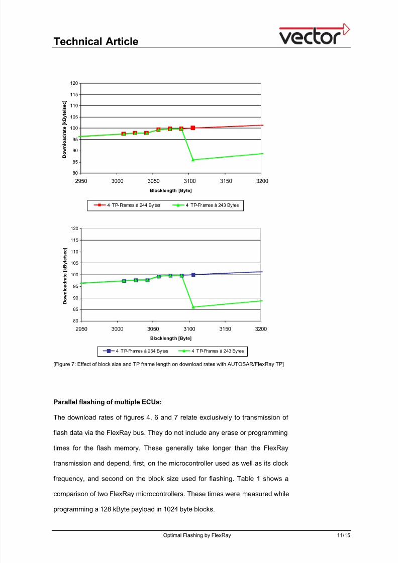
Figure 7 details this effect on an approx. 3 kByte block for larger variable frame
lengths. In this section, a TP frame length of 244 bytes demonstrates the best
performance, since block size has hardly any impact on the download rate.
Frames with 254 bytes would not improve the download rate. On the other
hand, if the frame length is 243 bytes and the block size is increased from 3090
to 3106 bytes, the download rate drops by a considerable 14 percent.
8/4/2019 Flash en Flex Ray ElektronikAutomotive 200711 Press Article En
http://slidepdf.com/reader/full/flash-en-flex-ray-elektronikautomotive-200711-press-article-en 11/15
Technical Article
Optimal Flashing by FlexRay 11/15
80
85
90
95
100
105
110
115
120
2950 3000 3050 3100 3150 3200
Blocklength [Byte]
D o w n l o a d r a t e [ k B y t e / s e c ]
4 TP-Frames à 244 By tes 4 TP-Frames à 243 By tes
80
85
90
95
100
105
110
115
120
2950 3000 3050 3100 3150 3200
Blocklength [Byte]
D o w
n l o a d r a t e [ k B y t e / s e c ]
4 TP-Frames à 254 By tes 4 TP-Frames à 243 By tes
[Figure 7: Effect of block size and TP frame length on download rates with AUTOSAR/FlexRay TP]
Parallel flashing of multiple ECUs:
The download rates of figures 4, 6 and 7 relate exclusively to transmission of
flash data via the FlexRay bus. They do not include any erase or programming
times for the flash memory. These generally take longer than the FlexRay
transmission and depend, first, on the microcontroller used as well as its clock
frequency, and second on the block size used for flashing. Table 1 shows a
comparison of two FlexRay microcontrollers. These times were measured while
programming a 128 kByte payload in 1024 byte blocks.

8/4/2019 Flash en Flex Ray ElektronikAutomotive 200711 Press Article En
http://slidepdf.com/reader/full/flash-en-flex-ray-elektronikautomotive-200711-press-article-en 12/15
Technical Article
Optimal Flashing by FlexRay 12/15
Eraserate (kByte/sec) Programmingrate(kByte/sec)
Clock
frequency 4 MHz 16 MHz 4 MHz 16 MHzController A 43,2 43,2 15,6 15,4
Controller B 111 121 42,7 80
[Table 1: Erase and programming rates of flash memories]
On microcontroller A, for example, the time needed to program a 2034 byte
block was 4 times as long as its FlexRay transmission (see also Figure 5). The
overall flash performance could be improved substantially if the flash tool were
to utilize programming and erase times to simultaneously program several
ECUs connected to FlexRay in parallel. However, the total number of FlexRay
slots required for flashing should not be increased. A precondition here is a
suitable TP, such as the ISO/FlexRay TP that is currently in preparation.
Optimizing verification:
Access protection mechanisms offer security by protecting the data from
potential manipulation during ECU flashing. Besides conventional methods
such as the seed & key method, signature methods implemented with the help
of cryptographic functions such as RSA (asymmetrical crypto-system) are also
used. By means of encrypted keys, signatures are computed within a trust
center and are then sent as supplemental information in the flash process. The
bootloader computes the expected signature and compares it to the transmitted
signature. Some automotive OEMs have been utilizing this quasi-standard
method for years using the Vector CANfbl.
Application cases
The ECU’s reprogramming process only covers a sub-aspect of the overall
flash process. OEMs and suppliers create their own special flashing concepts
8/4/2019 Flash en Flex Ray ElektronikAutomotive 200711 Press Article En
http://slidepdf.com/reader/full/flash-en-flex-ray-elektronikautomotive-200711-press-article-en 13/15
Technical Article
Optimal Flashing by FlexRay 13/15
for use in development, testing and integration phases as well as in end-of-line
programming and the service area. Different requirements in these processes
make it difficult to standardize the flash process. Nonetheless, in an attempt to
merge all of the sub-aspects related to flashing in the best possible way, ASAM
offers the ODX-F format as part of the ODX standard [2]. It defines a standard
for saving in a separately ODX-F container all information needed for flashing.
This involves storing in XML format the following different information in so-
called flash data containers: Pure flash data (payload), individual metadata,
data formats, value ranges and referencing to prepared OEM-specific flash
jobs. This assures both a smooth exchange of information (data and
interdependencies) between process participants and preservation of process
reliability. Another advantage is the practicable modularization of flash data,
making post-flashing of individual ECU functionalities (gear shifting program,
idle control, country variant, etc.) possible. The flash jobs are contained in the
diagnostic container (ODX-D). Both ODX-D container and flash container are
created by so-called authoring tools such as CANdelaStudio and CANdelaFlash
offered by Vector Informatik using the diagnostic descriptions out of CDD or
XML files, They are used as a common foundation, enable generation of
redundancy-free data and make it possible to avoid inconsistencies.
Outlook
Essentially, FlexRay offers fast data transmission up to 10 Mbit/sec, which
however cannot be fully exploited in flashing. However, today it is already
possible to flash typically six times faster than via CAN when the configurations
of bootloader, transport protocol and the FlexRay schedule are well
coordinated. Vector supports this effort with its FlexRay Flash Bootloader,
which already includes OEM-specific algorithms that have already proven
themselves for the CAN bus. If the flash job utilizes the programming time of
each individual flash block to transmit data to additional ECUs in parallel,

8/4/2019 Flash en Flex Ray ElektronikAutomotive 200711 Press Article En
http://slidepdf.com/reader/full/flash-en-flex-ray-elektronikautomotive-200711-press-article-en 14/15
Technical Article
Optimal Flashing by FlexRay 14/15
overall flash performance could be improved by another multiple. This
performance increase is possible both in flashing via CAN and via FlexRay,
wherein FlexRay also requires a special, very flexible TP. In a joint effort
between ISO and AUTOSAR, work is currently being done on a new
ISO/FlexRay TP standard. It should reduce the number of required FlexRay
slots to a minimum and dynamically adjust the frame length depending on
contents. This would by parallel programming of ECUs exploit the available
bandwidth optimally and is of special interest in parallel flashing via FlexRay in
sub-networks such as CAN or LIN.
Optimization of the flash process assumes specialized knowledge and
experience. Therefore, it is advisable to make use of the consultation services
of FlexRay specialists such as those at Vector. In the future, the complete,
universal Vector tool chain for all aspects of flashing – such as is already
available today for ODX with CANdelaStudio, CANdelaFlash, CANape and
CANdito as well as CANditoFlash – will also support flashing via FlexRay.
Revised: 11/2007
Word count: 2,890
Character count: 18,197
Figures:
Figure 0: Eyecatcher
Figure 1: Vector FlexRay flash bootloader – Overview of software modules and functional blocks
Figure 2: Phase of a flash processFigure 3: FlexRay schedule
Figure 4: Basic flow of the Transfer Data service with AUTOSAR/FlexRay TP
Figure 5: Maximum FlexRay download rates for a 128 kByte payload with AUTOSAR/FlexRay TP
Figure 6: FlexRay download rates for various TP frame lengths with AUTOSAR/FlexRay TP
Figure 7: Effect of block size and TP frame length on download rates with AUTOSAR/FlexRay TP
Table 1: Erase and programming rates of flash memories
All figures: Vector Informatik GmbH
Links:
[1] http://www.vector-informatik.com/vi_flexray_flashbootloader_en.html
[2] Patzer, A.: Richtiges “Flashen” [“Proper ‘Flashing’”].www.elektroniknet.de/home/automotive/technik-know-how/uebersicht/l/test-
entwicklungstools/richtiges-flashen-fuer-jede-aufgabenstellung/

8/4/2019 Flash en Flex Ray ElektronikAutomotive 200711 Press Article En
http://slidepdf.com/reader/full/flash-en-flex-ray-elektronikautomotive-200711-press-article-en 15/15
Technical Article
Optimal Flashing by FlexRay 15/15
Authors:
Pascale Morizur (Graduate Engineer, Dipl.-Ing.) studied Physics-Electronics at the Grande Ecole
ICPI in Lyon (France). Upon graduating in 1986, she worked for 10 years at MAN Commercial
Vehicles in the advance development area for CAN, J1939 and diagnostics. She is now employed atVector as Product Management Engineer in the area of FlexRay embedded software components.
Tel. +49-711/80670-2211, Fax +49-711/80670-111,
E-mail: [email protected]
Peter Liebscher (Graduate Engineer, Dipl.-Ing. (FH)) studied Communications Engineering at the FH
in Esslingen. Since 2002, he has been supporting the Embedded Software Components product line
at Vector Informatik GmbH as Business Development Manager.
Tel. +49-711/80670-413, Fax +49-711/80670-111,
E-mail: [email protected]
Vector Informatik GmbH
Ingersheimer Str. 24
D-70499 Stuttgart
Germany
www.vector-worldwide.com
Editorial contact: Holger Heit
Tel. 0711/80670-567, Fax 0711/80670-555,
E-mail: [email protected]