ENFK Grease Lubrication Pump Unit for use in progressive, single-line and dual-line
centralized lubrication systems
Operating instructions acc. to 98/37/EC, Annex II Bfor partly completed machinery
Assembly instructions acc. to EC Dir. 2006/42/EC
for partly completed machinery with associated operating instructions
Version 03

Page 2 EN
EC Declaration of Incorporation according to Machinery Directive 2006/42/EC, Annex II Part 1 B
The manufacturer SKF Lubrication Systems Germany GmbH ,Plaint Hockenheim, 2. Industriestraße 4, DE - 68766 Hockenheim hereby declares that the partly completed machinery:
Designation: Grease Lubrication Pump Unit
Type: AG. FK
Part no.: 774-*
Year of construction: See type identification platecomplies with the following basic requirements of the EC Machinery Directive 2006/42/EC at the time when first being launched in the market.
1.1.2 · 1.1.3 · 1.3.2 · 1.3.4 · 1.5.1 · 1.5.6· 1.5.8 · 1.5.9 · 1.6.1 · 1.7.1 · 1.7.3 · 1.7.4
The special technical documents were prepared following annex II part B of this directive. Upon justifiable request, these special technical documents can be forwarded electronically to the respective national authorities. The person empowered to assemble the technical documentation on behalf of the manufacturer is the head of standardization; see manufacturer‘s address.Furthermore, the following directives and harmonized standards were applied in the respective applicable areas:2011/65/EU RoHS II 2014/30/EU Electromagnetic compatibility | Industry
Standard Edition Standard Edition Standard Edition Standard Edition
DIN EN ISO 12100 2011 DIN EN 60947-5-1 2010 DIN EN 61000-6-2 2006 DIN EN 61000-6-4 2011
DIN EN 809 2012 DIN EN 61131-2 2008 Amendment 2011 DIN EN 60947-5-1 2010
DIN EN 60204-1 2007 Amendment 2009 DIN EN 61000-6-3 2011
Amendment 2010 DIN EN 60034-1 2015 Amendment 2012
DIN EN 50581 2013 DIN EN 61000-6-1 2007
The partly completed machinery must not be put into service until the final machinery into which it is to be incorporated has been declared in conformity with the pro-visions of the EC Machinery Directive 2006/42/EC and any other applicable directives.
Hockenheim, 2016/04/25
Jürgen Kreutzkämper Manager R&D GermanySKF Lubrication Business Unit
Stefan Schürmann Manager R&D Hockenheim/Walldorf SKF Lubrication Business Unit
EC Declaration of incorporation

Page 3 ENNotes
Grease lubrication pump units of the FK series
Imprint
The assembly/operating instructions are an in-
tegral component of the described product
and must be preserved for future use. The as-
sembly instructions with associated operating
instructions have been prepared in accordance
with the established standards and rules for
technical documentation VDI 4500 and
EN 292.
© SKF Lubrication Systems Germany GmbH
This documentation is protected by copyright.
SKF Lubrication Systems Germany GmbH re-
serves all rights, including those to the photo-
mechanical reproduction, duplication and dis-
tribution using special procedures (e.g., data
processing, data media and data networks) of
this documentation in whole or in part.
Subject to changes in contents and technical
information.
Service
If you have technical questions, please contact
the following addresses:
SKF Lubrication Systems Germany GmbH
Berlin Plant
Motzener Strasse 35/37
12277 Berlin Germany
Tel. +49 (0)30 72002-0
Fax +49 (0)30 72002-111
www.skf.com/lubrication
Hockenheim Plant
Industriestrasse 4
68766 Hockenheim Germany
Tel. +49 (0)62 05 27-0
Fax +49 (0)62 05 27-101
www.skf.com/lubrication

Page 4 ENTable of contents
Table of contents
Assambly instructions
Explanation of symbols and signs 5
Assembly instructions according to Machinery Directive 2006/42/EC, Annex VI 6
1. Safety instructions 7
2. Lubricants 8
2.1 General information 8
2.2 Selection of lubricants 8
2.3 Approved lubricants 9
2.4 Lubricants and the environment 10
3. Overview 10
4. Assembly 11
4.1 Assembly drawing 11
4.2 General information 12
4.2.2 Lubrication line arrangement 12 4.3 Assembly of pump unit 13
4.4 Electrical motor connection and ultrasonic ill level switch 14
4.5 Connection of ultrasonic sensor 15
4.6 Connection of 3/2 directional solenoid valves 16
4.7 Connection of radial piston pump 16
4.8 Notes on the CE marking 17
Operating instructions 19
1. Safety instructions 20
2. Lubricants 20
3. Transport and temporary storage 21
3.1 Lubrication unit 21
3.2 Electronic and electrical devices 21
3.3 General notes 21
4. Assembly 22
4.1 Information on assembly 22
4.2 Assembly of FK pump unit 22
4.3 Dismantling and disposal 22
5. Design and function 23
5.1 General information 23
5.2 Design 23
5.3 Functional description 24
6. Commissioning 27
6.1 Condition on delivery 27
6.2 Pre-commissioning information 27
6.3 Commissioning 28
6.4 Venting of pump elements 30
6.5 Coniguration of ultrasonic sensor 31
7. Shutdown 32
7.1 Temporary shutdown 32
7.2 Permanent shutdown 32
8. Faults, causes and remedies 33
8.1 Commissioning malfunctions 34
8.2 Operational malfunctions 35
8.2 Operational malfunctions 36
8.3 Malfunctions on ill level control 37
9. Maintenance 38
9.1 General information 39
10. Technical data 40
11. Wearing parts and spare parts 40
Information on
EC Directives 42
Manufacturer's Declaration 43
Declaration of Incorporation 44
Conformity assessment 45

Page 5 EN
Informational symbolsIndicators used with safety instructions
and their signiicance
Hazard symbols
Explanation of symbols
Explanation of symbols and signs
You will ind these symbols, which warn of speciic dangers to persons, material assets or the environment, next to all safety instructions
in these operating instructions.
Please heed these instructions and proceed
with special care in such cases. Please forward
all safety instructions to other users.
General hazard
DIN 4844-W9
Electrical voltage/current
Burn risk
Indicator Use
Danger! danger of bodily injury
Warning danger of damage to prop-erty and the environment
Note provides additional informa-tion
Note
prompts an action
used for itemizing
points out other facts, causes or consequences
provides additional information
Instructions placed directly on the machines/
grease lubrication pump units, such as:
arrow indicators
labels for luid connectionsmust be followed and kept in fully legible
condition.
You are responsible!
Please read the assembly and operating
instructions thoroughly and follow the safety
instructions.
DIN 4844-W8
Danger of being drawn into machinery

Page 6 ENAssembly instructions
Assembly instructions ac-cording to Machinery Direc-tive 2006/42/EC, Annex VI
The assembly instructions fulfill the Machinery
Directive indicated above with regard to “partly
completed machinery.” Partly completed ma-
chinery, which includes the product described
herein, is only intended to be incorporated into
or assembled with other machinery or other
partly completed machinery or equipment,
thereby forming machinery to which the
above-mentioned Directive applies.
Intended use
The FK grease lubrication pump unit is used
to supply centralized lubrication systems in
vehicles, systems and machines. The pump
unit delivers mineral oils or environmentally
compatible oils from ISO VG 46 to greases of
NLGI Grade 3. Consultation with a SKF Service
Center is required for synthetic oils. Any other
usage is deemed non-compliant with the in-
tended use.

Page 7 ENAssembly instructions
Assembly work
When performing any assembly work on ve-
hicles, machines and systems, the local acci-
dent prevention regulations as well as the
specific operational and maintenance specifi-
cations are to be followed.
1. Safety instructions
The FK grease lubrication pump unit is manu-
factured in accordance with the generally ac-
cepted rules and standards of industry prac-
tice, occupational safety and accident
prevention regulations. Risks may, however,
arise from its usage and may result in physical
harm to the user or others and in damage to
other material assets. The FK grease lubrica-
tion pump unit may only be used in proper
technical condition and in observance of the
assembly and operating instructions. In par-
ticular, any malfunctions which may affect
safety must be remedied immediately.
Warning
These operating instructions must be
read and properly understood by the
assembler and the responsible techni-
cal personnel/operator before assembly
and commissioning.
General Note
In addition to the operating instruc-
tions, general statutory regulations and
other binding regulations for accident
prevention and environmental pro-
tection (recycling/disposal) must be
observed and applied.
Authorized personnel
Only qualified personnel may install, operate,
maintain and repair the components described
in these instructions. Qualified personnel are
persons who have been trained, assigned and
instructed by the system operator. Such per-
sons are familiar with the relevant standards,
rules, accident prevention regulations and op-
erating conditions as a result of their training,
experience and instruction. They are autho-
rized to identify and perform necessary ac-
tions while avoiding potential risks. The defini-
tion of qualified personnel and the prohibition
against employing non-qualified personnel are
laid down in DIN VDE 0105 and IEC 364.
Electric shock hazard
Only appropriately trained qualified personnel
may establish electrical connections for the
devices in observance of the local conditions
for connections and local regulations (e.g.,
DIN, VDE). Significant bodily injury and prop-
erty damage may result from improperly con-
nected devices.
System pressure hazard
The systems may be pressurized. They must
be depressurized before starting upgrades,
changes or repairs.

Page 8 ENAssembly instructions
2. Lubricants
2.1 General information
All products from SKF Lubrication
Systems Germany GmbH may be used
only for their intended purpose and in
accordance with the information in the
product's assembly instructions.
Intended use is the use of the products for the
purpose of providing centralized lubrication/
lubrication of bearings and friction points us-
ing lubricants within the physical usage limits
which can be found in the documentation for
the devices, e.g. assembly instructions/operat-
ing instructions and the product descriptions,
e.g. technical drawings and catalogs.
Hazardous materials of any kind, especially
the materials classified as hazardous by CLP
Regulation EC 1272/2008 may only be used
to fill SKF centralized lubrication systems and
components and deliv-ered and/or distributed
with the same after consulting with and re-
ceiving written approval from SKF.
No products manufactured by
SKF Lubrication Systems Germany GmbH are
approved for use in conjunction with gases,
liquefied gases, pressurized gases in solution,
vapors or such fluids whose vapor pressure
exceeds normal atmospheric pressure (1013
mbar) by more than 0.5 bar at their maximum
permissible temperature. Other media which
are neither lubricant nor hazardous substance
may only be fed after consultation and written
approval from SKF Lubrication Systems
Germany GmbH. SKF Lubrication Systems
Germany GmbH considers lubricants to be a
component of the system design which must
be factored into the selection of components
and the design of centralized lubrication sys-
tems. The lubricating properties of the lubri-
cants are critically important in these
considerations.
2.2 Selection of lubricants
Observe the instructions from the
machine manufacturer regarding the
lubricants that are to be used.
The amount of lubricant required at
a lubrication point is speciied by the
bearing or machine manufacturer. It
must be ensured that the required
quantity of lubricant is provided to the
lubrication point. The lubrication point
may otherwise not receive adequate
lubrication, which can lead to damage
and failure of the bearing.
Selection of a lubricant suitable for the lubri-
cation task is made by the machine/system
manufacturer and/or the operator of the ma-
chine/system in cooperation with the lubricant
supplier. The bearings/friction points that re-
quire lubrication, their expected load during
operation and the expected ambient condi-
tions are taken into account during selection in
consideration of economic and environmental
aspects.
Where necessary, SKF Lubrication Systems
Germany GmbH supports customers in the

Page 9 ENAssembly instructions
selection of suitable components for feeding
the selected lubricant and in the planning of
the SKF lubrication system.
SKF Lubrication Systems Germany
GmbH supports customers in the
selection of suitable components for
feeding the selected lubricant and in
the planning and design of a lubrication
system. Please contact SKF Lubrication
Systems Germany GmbH if you have
further questions regarding lubricants.
Lubricants can be laboratory tested for
feedability (e.g., "bleeding") in central-
ized lubrication system applications.
An overview of the lubricant tests
offered by SKF Lubrication Systems
Germany GmbH can be requested from
the Service Center of SKF Lubrication
Systems Germany GmbH.
2.3 Approved lubricants
Only lubricants approved for the prod-
uct may be used. Unsuitable lubricants
can lead to failure of the product and to
property damage.
Different lubricants cannot be mixed, as
mixing may result in damage and ne-
cessitate costly and complicated clean-
ing of the product/lubrication system.
It is recommended that an indication of
the lubricant in use be attached to the
lubricant reservoir in order to prevent
accidental mixing of lubricants.
The product described here can be operated
using lubricants that meet the specifications in
the technical data. Depending on the product
design, these lubricants may be oils, fluid
greases or greases. Oils and base oils may be
mineral, synthetic and/or rapidly biodegrad-
able. Consistency agents and additives may be
added depending on the operating conditions.
Note that in rare cases, there may be lubri-
cants whose properties are within permissible
limit values but whose other characteristics
render them unsuitable for use in lubrication
systems. For example, synthetic lubricants
may be incompatible with elastomers.
Page 10 ENAssembly instructions
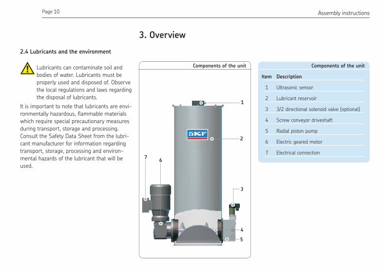
3. Overview
Components of the unit
Item Description
1 Ultrasonic sensor
2 Lubricant reservoir
3 3/2 directional solenoid valve (optional)
4 Screw conveyor driveshaft
5 Radial piston pump
6 Electric geared motor
7 Electrical connection
Components of the unit
1
2
3
5
4
67
2.4 Lubricants and the environment
Lubricants can contaminate soil and
bodies of water. Lubricants must be
properly used and disposed of. Observe
the local regulations and laws regarding
the disposal of lubricants.
It is important to note that lubricants are envi-
ronmentally hazardous, flammable materials
which require special precautionary measures
during transport, storage and processing.
Consult the Safety Data Sheet from the lubri-
cant manufacturer for information regarding
transport, storage, processing and environ-
mental hazards of the lubricant that will be
used.
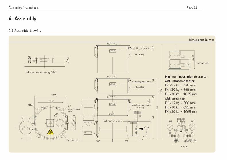
Page 11 ENAssembly instructions
Dimensions in mm
MODE
BA
TEACH-IN
AA
34
M1
2x1
18
5
MB MA
FK.../15kg
FK.../30kg
FK.../60kg
62
0
Ø355
Ø11.5
330
270
R20
335
268
Ø324
51
05
42
53
4
99
0
50
“A”
50
90
min
. 75
60
4.1 Assembly drawing
4. Assembly
Fill level monitoring "U2"
Minimum installation clearance:
with ultrasonic sensor
FK../15 kg = 470 mm
FK../30 kg = 665 mm
FK../30 kg = 1035 mm
with screw cap
FK../15 kg = 500 mm
FK../30 kg = 695 mm
FK../30 kg = 1065 mmView without valve
Screw cap

Page 12 ENAssembly instructions
4.2 General information
4.2.1 Hydraulic line connection (General)
The hydraulic line must be connected to the
lubrication unit in such a way that no forces
can be transferred to the assembled lubrica-
tion unit (stress-free connection).
Warning
Before connecting the lubrication unit
to the hydraulic supply, it must be
ensured that the hydraulic supply is
depressurized.
Warning
The maximum hydraulic oil pressure
indicated for operating the hydraulically
actuated lubrication unit may not be
exceeded.
4.2.2 Lubrication line arrangement
Observe the following instructions when ar-
ranging the main lubricant lines and lubrica-
tion point lines in order to ensure that the
entire lubrication system functions smoothly.
The main lubricant line must be dimensioned
in accordance with the maximum pressure
that occurs during operation and the delivery
volume of the lubrication unit used. If possible,
the main lubricant line should rise upward
from the lubrication unit and be ventable at
the highest point on the lubrication line sys-
tem. Lubricant distributors at the end of the
main lubricant line must be installed such that
the lubrication point lines point upwards. If the
system configuration requires that the lubri-
cant distributors be arranged below the main
lubricant line, they should not be placed at the
end of the main lubricant line.
The pipes, tubes, shutoff valves and directional
control valves, fittings, etc. that will be used
must be designed for the maximum operating
pressure of the lubrication unit, the permis-
sible temperatures and the lubricants that will
be delivered. All components of the lubrication
line system such as pipes, tubes, shutoff
valves and directional control valves, fittings,
etc. must be carefully cleaned before assem-
bly. No seals should point inward in the lubri-
cation line system, as this could hinder lubri-
cant flow and introduce contaminants into the
lubrication line system.

Page 13 ENAssembly instructions
The FK grease lubrication pump unit must be
installed on a level surface. The pump's base
plate must not be under stress. Sufficient
space must be provided during installation for
later service and maintenance work.
Warning
When drilling the assembly holes, you
must be careful of any supply lines or
other units, as well as of other hazards
such as moving parts.
Maintain safety clearances and comply
with local regulations for assembly and
accident prevention.
Warning
Do not tilt or drop the FK grease lubri-
cation pump unit!
Warning
The reservoir cover must be installed
before turning on or commissioning
the FK pump units. The rotating screw
conveyor driveshaft may cause injury if
the reservoir cover is not installed.
The FK grease lubrication pump unit is
installed using 4 screws (and washers).
If M10 tapped bores are used to fasten the
unit, the screws must have a minimum length
of 20 mm.
Fastening material provided by the customer:
Hexagon head screws (4x) acc. to
DIN933-M10x20-8.8
Washers (4x) acc. to.
DIN 125-B10.5-St
4.3 Assembly of pump unit

Page 14 ENAssembly instructions
Ø11.5270
R20
335
Fig. 2 Assembly holes in mm Drill assembly holes (M10) acc. to assembly
drawing (Fig. 2) and the conditions on the
surface.
Clean surface to remove drilling chips.
Place the pump unit on the surface and
roughly align it.
Pass hexagon head screws (4x)
acc. to (DIN933-M10x20-8.8) with associ-
ated washers (4x) acc. to DIN 125-B10.5-
St through the ixing holes on the pump
baseplate and apply the screws to the M10
threads on the surface.
Gently tighten hexagon head screws (4x).
Align pump unit, tighten hexagon head
screws with following torque:
Torque 50 Nm
4.4 Electrical motor connection and
ultrasonic ill level switch
Connect pump unit motor according to
the motor rating plate (1) and the motor
characteristics.
Electric shock hazard
Only appropriately trained qualiied
personnel may establish electrical con-
nections for the devices in observance
of the local conditions for connections
and local regulations (e.g., DIN, VDE).
Signiicant bodily injury and property
damage may result from improperly
connected devices.
Warning
Connect lines in accordance with the
technical speciications and the local
conditions for connections and local
regulations (e.g., DIN, VDE).
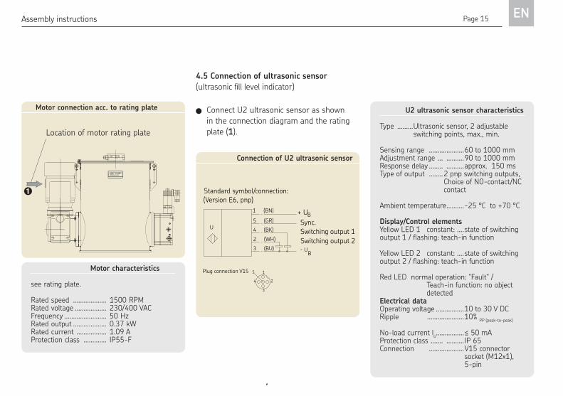
Page 15 ENAssembly instructions
Connection of U2 ultrasonic sensor
Standard symbol/connection:(Version E6, pnp)
U (BK)4
3
2
(BU)
(WH)
1
5
(BN)
(GR)
Switching output 2
Switching output 1
- U
BSync.
+ U
B
Plug connection V15
2
3
4
5 1
Motor connection acc. to rating plate
Location of motor rating plate
Connect U2 ultrasonic sensor as shown
in the connection diagram and the rating
plate (1).
Motor characteristics
see rating plate.
Rated speed ................... 1500 RPMRated voltage .................. 230/400 VACFrequency ........................ 50 HzRated output ................... 0.37 kWRated current ................. 1.09 AProtection class ............. IP55-F
4.5 Connection of ultrasonic sensor (ultrasonic ill level indicator)U2 ultrasonic sensor characteristics
Type .........Ultrasonic sensor, 2 adjustable switching points, max., min.
Sensing range ....................60 to 1000 mmAdjustment range ... ..........90 to 1000 mmResponse delay ........ ..........approx. 150 msType of output ........2 pnp switching outputs, Choice of NO-contact/NC contact
Ambient temperature ..........-25 °C to +70 °C
Display/Control elementsYellow LED 1 constant: ....state of switching output 1 / flashing: teach-in function
Yellow LED 2 constant: ....state of switching output 2 / flashing: teach-in function
Red LED normal operation: "Fault" / Teach-in function: no object detectedElectrical dataOperating voltage ................10 to 30 V DCRipple .....................10%
PP (peak-to-peak)
No-load current lo ................≤ 50 mA
Protection class ....... ..........IP 65Connection ....................V15 connector socket (M12x1), 5-pin

Page 16 ENAssembly instructions
Labeling of max. operating pressure
4.7 Connection of radial piston pump
(see operating instructions, Chapter 4)
All pump designs (F1, F2, F3 or F4) of the FK
pump unit have the same pipe thread G1/2".
The G1/2" screw union and the downstream
piping or tubing must correspond to the maxi-
mum permissible operating pressure for the
pump unit. Depending on the pump usage
and lubrication system (progressive, single-
line or dual-line system), the maximum oper-
ating pressure can be 200 bar, 300 bar or
400 bar.
The specification for the factory-set maximum
operating pressure is contained in the order
number and should be obtained from the or-
der confirmation. The rating plate can also be
used for further verification. Item 8 of the type
designation contains the max. operating pres-
sure of 200 bar, 300 bar or 400 bar.
SKF Lubrication Systems Germany GmbH
recommends only choosing screw unions,
pipes and tube connections from the heavy-
duty series.
Screw unions on pump
MB MA
Screw union G 1/2"
Type designation FK..
M
X XX...................
Grease/Fett NLGI-3 max.
FK..................................
774-...........................
Example:
FK 2 / 15 U2 1M 04 / 6 / 400 M2 3 / 0001 AF 07
4.6 Connection of 3/2 directional solenoid
valves (reversing valves on pump de
signs FK1 and FK2)
3/2 directional solenoid valve characteristics
Basic position ............... de-energized closed
Manual actuation ......... yes
Voltages ........................ 24 V DC
Rated current ............... 0.67 A
Rated output ................. 20 W
ON-time ........................ 100% ON-time
(at max. +35°C)
Protection class ........... IP 65
Plug connection .......... DIN 43650-AF3
Connection diagram for 3/2 directional solenoid valve
Connect 3/2 directional solenoid valve(s)
acc. to connection diagram

Page 17 ENAssembly instructions
Warning
Information beyond the actual as-
sembly procedure is contained in the
included operating instructions. The
assembly and operating instructions
are therefore considered an inseparable
part of the documentation.
The operating instructions are divided into the
chapters:
1. Safety instructions
2. Transport and temporary storage
3. Assembly
4. Design and function
5. Commissioning
6. Faults, causes and remedies
7. Maintenance
8. Technical data
9. Wearing parts and spare parts
(see Table of contents, Page 4)
These assembly instructions and the
included operating instructions must be
read and properly understood by the
assembler and the responsible technical
personnel/operator before assembly.
Note on the rating plate
Rating plates on FK grease lubrication pump
units provide important key data such as the
type designation, order number, barcode and
serial number.
To avoid loss of this data in case the rating
plate becomes illegible, these characteristics
should be entered in the following table.
Enter key data from rating plate in the fol-
lowing table:
Type designation
Made in Germany
XXX...................
Grease/Fett NLGI-3 max.
FK..................................
774-...........................
Serial number
4.8 Notes on the CE marking
The CE marking is performed following the requirements stated in the applied standards:
○ 2014/30/EU Electromagnetic
Compatibility
○ 2011/65/EU (RoHS II) Directive on the
restriction of the use of certain ha-
zardous substances in electrical and
electronic equipment
Notes on the Low Voltage Directive
The protective regulations of the low voltage
directive 2014/35/EU are complied with
according to annex I, no. 1.5.1 of machinery
directive 2006/42/EC.
Notes on the Pressure Equipment Directive
2014/68/EU
Due to its performance rates the product
does not achieve the limit values fixed in
article 4 (1)(a)(i) and is excluded from the
scope of the pressure equipment directive
2014/68/EC article 4(3).

Page 18 EN
Page 19 EN
FK Grease Lubrication Pump Unit for use in progressive, single-line and dual-line
centralized lubrication systems
Original operating instructionsacc. to 98/37/EC, Annex II B
for partly completed machinery
Operating instructions associated with assembly instructions according to EC Dir. 2006/42/EC for partly completed machinery
Page 20 EN 1. Safety instructions / 2. Lubricants
1. Safety instructions
Warning
These operating instructions must be
read and properly understood by the
assembler and the responsible techni-
cal personnel/operator before assembly
and commissioning.
The safety instructions listed in
Chapter 1, "Safety instructions," of
the assembly instructions also apply
without restrictions to these operat-
ing instructions.
General
Note
In addition to the operating instruc-
tions, general statutory regulations and
other binding regulations for accident
prevention and environmental pro-
tection (recycling/disposal) must be
observed and applied.
2. Lubricants
Warning
The information on lubricants listed in
Chapter 2, "Lubricants," of the assem-
bly instructions also applies without
restrictions to these operating instruc-
tions.
Disclaimer of liability
SKF Lubrication Systems Germany GmbH
shall not be held liable for damages:
caused by contaminated or unsuitable
lubricants
caused by the installation of non-original
SKF components or SKF spare parts
caused by inappropriate usage
resulting from improper assembly, conigu-
ration or illing
resulting from improper response to mal-
functions
caused by independent modiication of
system components
Only media approved for these types of
pump units may be used. Unsuitable media
may result in pump unit failure and po-
tentially severe bodily injury and property
damage.

Page 21 EN
3. Transport and temporary storage
Warning
The product must not be tilted or
dropped.
3. Transport and temporary storage
SKF Lubrication Systems Germany GmbH
products are packaged in accordance with
standard commercial practice according to the
regulations of the recipient's country and
DIN ISO 9001. During transport, safe handling
must be ensured and the product must be
protected from mechanical effects such as im-
pacts. The transport packaging must be
marked with the "Do not drop!".
There are no restrictions for land, air or sea
transport. After receipt of the shipment, the
product(s) must be inspected for damage and
for completeness according to the shipping
documents. The packaging material must be
preserved until any discrepancies are resolved.
SKF Lubrication Systems Germany GmbH
products are subject to the following storage
conditions:
3.1 Lubrication units
Ambient conditions: dry and dust-
free surroundings, storage in well venti-
lated dry area
Storage time: max. 24 months
Permissible humidity: < 65%
Storage temperature: 10 - 40°C
Light: Avoid direct sun or UV exposure and
shield nearby sources of heat
3.2 Electronic and electrical devices
Ambient conditions: dry and dust-
free surroundings, storage in well venti-
lated dry area
Storage time: max. 24 months
Permissible humidity: < 65%
Storage temperature: 10 - 40°C
Light: Avoid direct sun or UV exposure and
shield nearby sources of heat
3.3 General notes
The product(s) can be enveloped in plastic
ilm to provide low-dust storage
Protect against ground moisture by storing
on a shelf or wooden pallet
Bright-inished metallic surfaces, especially
wearing parts and assembly surfaces, must
be protected using long-term anti-corro-
sive agents before storage
At approx. 6-month intervals: Check for
corrosion. If there are signs of corrosion,
reapply anti-corrosive agents.
Drives must be protected against mechan-
ical damage

Page 22 EN4. Assembly/Connection
4.1 Information on assembly
The assembly procedure for FK pump units is
described in detail in the assembly instructions
associated with these operating instructions.
Information/instructions about assembling the
FK pump unit beyond the scope of the assem-
bly instructions are contained later in this
chapter.
4. Assembly
4.2 Assembly of FK pump unit
Assembly must be performed in accordance
with the included assembly instructions
and the additional information/instructions
contained in this chapter.
Warning
The applicable national environmental
regulations and statutes are to be ad-
hered to when dismantling and dispos-
ing of the grease lubrication pump unit.
The product can also be returned to
SKF Lubrication Systems Germany
GmbH for disposal, in which case the
customer is responsible for reimbursing
the costs incurred.
4.3 Dismantling and disposal

Page 23 EN5. Design and function
5. Design and function
5.1 General information
The FK pump unit is a multi-function piston
pump whose modular design makes it very
versatile.
The FK pump unit can be used as a progres-
sive, single-line or dual-line pump unit with or
without integrated reversing valves. The mod-
ular design of the pump also allows it to be
retroitted from one of the above-mentioned lubrication systems to another system.
Retroitting can only be performed by SKF Service and is therefore not described in these
instructions.
5.2 Design
The FK grease lubrication pump unit, which
was designed to handle demanding usage, is
available in reservoir sizes of 15 kg, 30 kg and
60 kg. A screw conveyor driveshaft fastened
to the geared motor drives the pump unit and feeds grease to the radial piston pump langed to the opposite side. Depending on the delivery
output required, the radial piston pump can
be equipped with up to six pump elements
(internally consolidated). Based on the ap-
plication, the radial piston pump is supplied as
a progressive, single-line or dual-line pump,
with or without reversing function. Grease
level monitoring is performed by an ultrasonic
sensor. A sensor with maximum and minimum
switching points is provided.
FK pump designs
C
A
B
A
B
C
AB
TEACH-IN
MODE
MODE
BA
TEACH-IN
AA
AA
MODE
BA
TEACH-IN
AA
99
06
20
42
5
Made in Germany
...................
R
FK.../15...
FK.../30...
FK.../60...
Ausführung "U2"
FK..................................
Grease/Fett NLGI-2 max.774-...........................
Page 24 EN
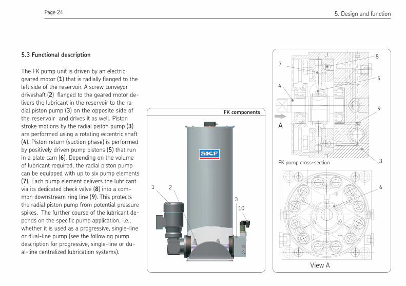
The FK pump unit is driven by an electric
geared motor (1) that is radially flanged to the
left side of the reservoir. A screw conveyor
driveshaft (2) flanged to the geared motor de-
livers the lubricant in the reservoir to the ra-
dial piston pump (3) on the opposite side of
the reservoir and drives it as well. Piston
stroke motions by the radial piston pump (3)
are performed using a rotating eccentric shaft
(4). Piston return (suction phase) is performed
by positively driven pump pistons (5) that run
in a plate cam (6). Depending on the volume
of lubricant required, the radial piston pump
can be equipped with up to six pump elements
(7). Each pump element delivers the lubricant
via its dedicated check valve (8) into a com-
mon downstream ring line (9). This protects
the radial piston pump from potential pressure
spikes. The further course of the lubricant de-
pends on the specific pump application, i.e.,
whether it is used as a progressive, single-line
or dual-line pump (see the following pump
description for progressive, single-line or du-
al-line centralized lubrication systems).
A
View A
FK components
4
8
5
9
3
7
6
FK pump cross-section
1
3
10
2
5.3 Functional description
5. Design and function

Page 25 EN
Pump unit for progressive centralized
lubrication systems (FK4)
Lubricant that comes from the ring line (9) is
delivered to pump outlet "A/P". From there it
is passed to the downstream progressive
feeders.The pump outlet "B/R" is closed on
pump design FK4.
Pump unit for single-line centralized
lubrication systems (FK1)
Lubricant that comes from the ring line (9) is
delivered to the inlet of the 3/2 directional
solenoid valve (10) flanged to the pump. The
lubricant flows to pump outlet A/P if the
directional solenoid valve is actuated. After
this, the lubricant is passed on through the
main lubricant line to the downstream single-
line progressive feeders. When the 3/2
directional solenoid valve is in a de-energized
state, pressure relief of the main lubricant line
returns to the lubricant reservoir (T).
G1/2E
A/PM R
P
B/R
G1/4”
C
A
B
C
A
B
G1/2”
G1/4”
G1/2”
G1/4”
MATT T
MB/R
A/P
T MB
A
View A
M3~
FK4 connection drawing
G1/4”G1/4”
MAMB
A/PMB/R
M
G1/4”
AB
C
A
B
C
G1/2”
G1/4”
A/P
TT T MA
B/R
E
MBT
A
View A
G1/2”
G1/4”
G1/2”
M3~
FK1 connection drawing
5. Design and function

Page 26 EN
Pump unit for dual-line centralized lubrica-
tion systems without installed reversing
valves (FK3)
Lubricant that comes from the ring line (9) is
delivered to pump outlet "A/P". From there it
is passed to the downstream external revers-
ing valves.The pump outlet "B/R" serves to re-
turn the lubricant from the downstream
changeover valve or pressure relief of one
of the two main lines into the lubricant reser-
voir (T).
Pump unit for dual-line centralized lubrica-
tion systems with integrated reversing
valves (FK2)
Lubricant that comes from the ring line (9) is
delivered to the inlets of both 3/2 directional
solenoid valves (10). If the 3/2 directional so-
lenoid valve for connection A is actuated, the
lubricant flows to outlet A. From there it is
passed through the connected main lubricant
line to the downstream dual-line distributors.
At the same time, pressure in the second main
lubricant line is relieved. This is performed via
the second, non-actuated directional solenoid
valve B and returns to the lubricant reservoir
(T). When the required system pressure is
reached, both directional solenoid valves
switch over such that the main lubricant line
that has been pressurized is relieved and the
unpressurized main lubricant line is pressur-
ized. In a de-energized state, both main lines
are relieved.
A/PM
RP
PR
B/R
G1/4”
C
A
B
B
C
A
G1/4”
G1/2”
G1/2”
G1/4”G1/2”
MA
A/P
B/RM
MBT
E
TT T
A
View A
M3~
FK3 connection drawing
FK2 connection drawing
G1/4”
„
60
G1/2”
A/PMB/R
MAMB
G1/4”
G1/4”
G1/4”
A
C
B
C
BA
G1/2”
MA
A/P
B/R
M
T MB
E
TTT
G1/2”
G1/2”
G1/4”
A
View A
M3~
5. Design and function

Page 27 EN
6.2 Pre-commissioning information
Warning
The reservoir cover must be installed
before commissioning the FK pump
units. The rotating screw conveyor
driveshaft may cause injury if the res-
ervoir cover is not installed.
Warning
The grease lubrication pump unit may
only be illed via the iller socket. Fill-
ing through the reservoir cover may
introduce air pockets and contaminate
the ill level monitoring system, and is
therefore not permitted.
The product described here functions
automatically. The lubricant transport in
the lubricant lines should, however, be
6. Commissioning
6.1 Condition on delivery
On delivery, the radial piston pump on the grease lubrication pump unit is already equipped with one to a maximum of six pump elements according to the required delivery volume. The grease lubrication pump has al-ready been tested using oil and vented.
6. Commissioning
subjected to regular visual inspection.
The lubricant ill level in the lubricant
reservoir, if present, should likewise
be subjected to regular visual inspec-
tion. If the lubricant ill level is too low,
lubricant needs to be added up to the
maximum mark as described in the
"Commissioning" chapter.
Note
Observe the instructions from the
machine manufacturer regarding the
lubricants that are to be used.
Warning
Only ill using clean lubricant and an
appropriate device. Contaminated lubri-
cants can result in severe system mal-
function. The lubricant reservoir must
be illed without introducing bubbles.
Warning
Different lubricants cannot be mixed, as
mixing may result in damage and ne-
cessitate costly and complicated clean-
ing of the product/lubrication system.
It is recommended that an indication of
the lubricant in use be attached to the
lubricant reservoir in order to prevent
accidental mixing of lubricants.

Page 28 EN
Warning
The direction of driveshaft rotation is
indicated on each pump unit by an ar-
row on the pump motor. The direction
of rotation must match the arrow.
Switch on the FK grease lubrication pump unit briely (approx. 1 second).
Check the direction of motor rotation
based on the arrow attached to the motor
housing.
Before the product is commissioned, all
electrical, hydraulic and pneumatic (if present)
connections must be inspected.
The lubricant may only be fed without bub-
bles. The lubricant reservoir, if present, must
be filled with clean lubricant without introduc-
ing bubbles. The product is then operated until
lubricant without bubbles is discharged at all
lubrication points.
The process of venting the lubrication system
can be facilitated by:
Performing initial commissioning only
without lubricant lines connected
Filling the FK grease lubrication pump
unit with lubricant via the iller socket
Connecting electrical connections and
electrical lines in accordance with the
technical speciications (rating plate) and
the local conditions for connections and
local regulations
Reservoir cover and filler socket
MB MA
Filler socket G 1/2"
AB
TEACH-IN
MODE
AA
Made in Germany
...................
R
FK..................................
Grease/Fett NLGI-2 max.774-...........................
6.3 Commissioning
Arrow indicator on pump motor
AB
TEACH-IN
MODE
AA
Made in Germany
...................
R
FK..................................
Grease/Fett NLGI-2 max.774-...........................
6. Commissioning

Page 29 EN
The following procedure varies based on
the pump unit design.
FK4 (for progressive systems)
see FK4 connection drawing on Page 25
After several minutes (depending on the
number of installed pump elements),
bubble-free grease should discharge
from pump outlet "P". If this does not
occur, the pump must be vented again as
described in Chapter 6.4.
FK3 (for dual-line centralized lubrication
sys tems with separate changeover valves)
see FK3 connection drawing on Page 26
After several minutes (depending on the
number of installed pump elements),
bubble-free grease should discharge from
pump outlet "P".
If this does not occur, the pump must be
vented again as described in Chapter 6.4.
FK1 (for single-line centralized lubrication
systems)
see FK1 connection drawing on Page 25
Prerequisite:
The 3/2 directional solenoid valve must
be connected and switched to pass-
through ("A" to "P").
After several minutes (depending on the
number of installed pump elements),
bubble-free grease should discharge from
pump outlet "P".
If this does not occur, the pump must be
vented again as described in Chapter 6.4.
FK2 (for dual-line centralized lubrication
systems with changeover valves
attached to pump)
see FK2 connection drawing on Page 26
Prerequisite:
Both 3/2 directional solenoid valves must
be connected; if the directional solenoid
valve with A/P connections is switched to
connection A, bubble-free grease must
discharge from outlet A.
If the directional solenoid valve with B/R
connections is switched to connection B,
bubble-free grease must discharge from
outlet B.
After several minutes (depending on the
number of installed pump elements),
bubble-free grease should discharge from
pump outlet "A" or "B".
If this does not occur, the pump must be
vented again as described in Chapter 6.4.
Repeat procedure with directional
solenoid valves switched to opposite con-
nections.
Turn off FK grease lubrication pump unit
6. Commissioning

Page 30 EN
6.4 Venting of pump elements
6. Commissioning
Venting of FK pump unit
MB MA
Remove screw unions (or pressure gauge
screw) from connection MB (1)
Allow FK pump unit to run until grease
without bubbles discharges from the hole
for connection MB
Apply screw unions (or pressure gauge
screw) to connection MB
Tighten screw unions (or pressure gauge
screw)
MB

Page 31 EN6. Commissioning
6.5 Coniguration of U2 ultrasonic sensorWarning
The max./min. switching points are
factory-set based on the reservoir
size of the pump unit. If the switch-
ing points need to be adjusted by the
user, the parameters must be set as
described below.
Parameterization
The sensor parameters can be set using two
buttons. Button A1 is used to start the teach-
in mode for switching point 1, and button A2 is
used to start the teach-in mode for switching
point 2. The sensor switches to sensitivity ad-
justment mode if both buttons are pressed
when the power is turned on. If parameteriza-
tion is not completed within five minutes, the
sensor terminates the procedure and leaves
the settings unchanged.
Teaching-in of switching points:
Teaching-in switching point A1
(maximum with button A1)
Press membrane button A1 >2 s
The sensor enters teach-in mode for
switching point 1 (A1)
Position the target object at the desired
distance
The sensor's LEDs show whether the
target object is detected. When the object
is detected, the yellow LED flashes; when
it is not detected, the red LED flashes.
Briefly press membrane button A1
The sensor ends the teach-in procedure for switching point 1 and saves the value in non-volatile memory. The taught-in value is invalid in case of an uncertain object (red LED lashes irregularly). The teach-in mode is left.
The teach-in procedure for switching point A2
(minimum) is performed using button A2
34
AA
MO
DE
A
TE
AC
H-I
N
B
Detection range
Close range
Reservoir level maximum
A1
A2
Longest sensing distance
Shortest sending distance
Objekt (grease)
Beam angle
Reservoir level minimum
LED-window
Membrane keypad
Configuration of U2 ultrasonic sensor

Page 32 EN
7.1 Temporary shutdown
The described product is temporarily shut
down by disconnecting the electrical, pneu-
matic and/or hydraulic supply connections. The
safety instructions in these assembly instruc-
tions must be observed.
If the product will be shut down for an exten-
ded period of time, the instructions in Chapter
3, "Transport and storage," of these operating
instructions must be observed.If the product is
recommissioned, the instructions in the
Chapters "Assembly" and "Commissioning" in
the assembly instructions and operating inst-
ructions must be observed.
7.2 Permanent shutdown
If the product will be permanently shut down,
the local regulations and laws regarding the
disposal of contaminated equipment must be
observed.Lubricants can contaminate soil and
bodies of water.
Warning
Lubricants must be properly used and
disposed of. Observe the local regula-
tions and laws regarding the disposal of
lubricants.
7. Shutdown
7. Shutdown
Page 33 EN
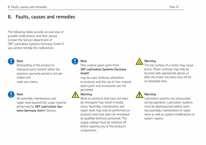
8. Faults, causes and remedies
The following tables provide an overview of
possible malfunctions and their causes.
Contact the Service department of
SKF Lubrication Systems Germany GmbH if
you cannot remedy the malfunction.
Note
Dismantling of the product or
individual parts thereof within the
statutory warranty period is not per-
mitted and
voids any claims.
Note
All assembly, maintenance and
repair work beyond this scope must be
performed by SKF Lubrication Sys-
tems Germany GmbH Service.
8. Faults, causes and remedies
Warning
Work on products that have not been
de-energized may result in bodily
injury. Assembly, maintenance and
repair work may only be performed on
products that have been de-energized
by qualiied technical personnel. The
supply voltage must be switched off
before opening any of the product's
components.
Note
Only original spare parts from
SKF Lubrication Systems Germany
GmbH
may be used. Arbitrary alterations
to products and the use of non-original
spare parts and accessories are not
permitted.
Warning
The hot surface of a motor may cause
burns. Motor surfaces may only be
touched with appropriate gloves or
after the motor has been shut off for
an extended time.
Warning
Lubrication systems are pressurized
during operation. Lubrication systems
must be depressurized before start-
ing assembly, maintenance or repair
work as well as system modiications or
system repairs.
Page 34 EN
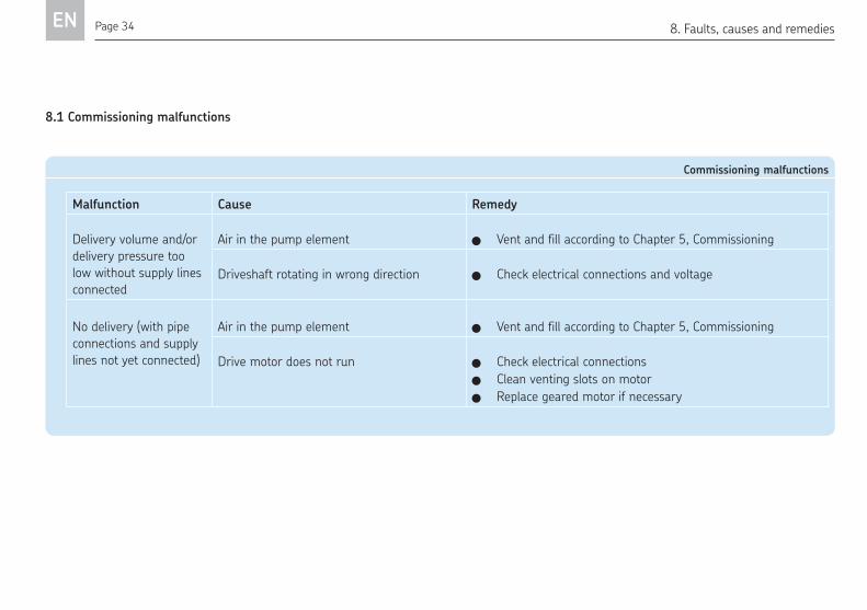
8.1 Commissioning malfunctions
Commissioning malfunctions
Malfunction Cause Remedy
Delivery volume and/or
delivery pressure too
low without supply lines
connected
Air in the pump element Vent and fill according to Chapter 5, Commissioning
Driveshaft rotating in wrong direction Check electrical connections and voltage
No delivery (with pipe
connections and supply
lines not yet connected)
Air in the pump element Vent and fill according to Chapter 5, Commissioning
Drive motor does not run Check electrical connections
Clean venting slots on motor
Replace geared motor if necessary
8. Faults, causes and remedies
Page 35 EN
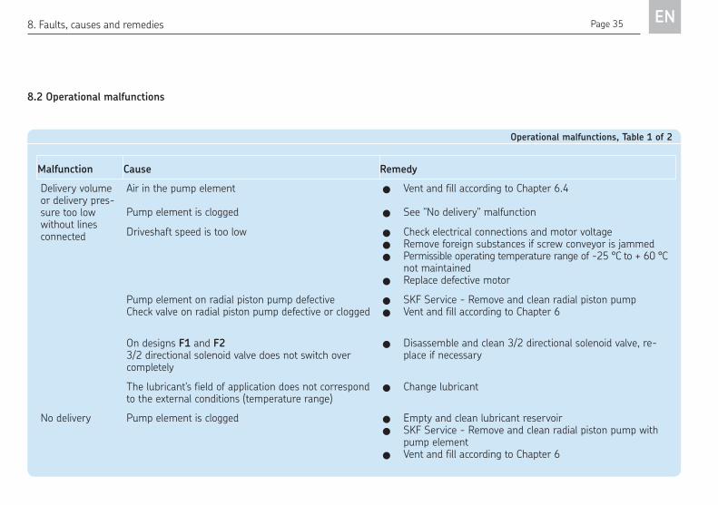
8.2 Operational malfunctions
8. Faults, causes and remedies
Operational malfunctions, Table 1 of 2
Malfunction Cause Remedy
Delivery volume or delivery pres-sure too low without lines connected
Air in the pump element Vent and fill according to Chapter 6.4
Pump element is clogged See "No delivery" malfunction
Driveshaft speed is too low Check electrical connections and motor voltage Remove foreign substances if screw conveyor is jammed Permissible operating temperature range of -25 °C to + 60 °C
not maintained Replace defective motor
Pump element on radial piston pump defective Check valve on radial piston pump defective or clogged
SKF Service - Remove and clean radial piston pump Vent and fill according to Chapter 6
On designs F1 and F2 3/2 directional solenoid valve does not switch over completely
Disassemble and clean 3/2 directional solenoid valve, re-place if necessary
The lubricant's field of application does not correspond to the external conditions (temperature range)
Change lubricant
No delivery Pump element is clogged Empty and clean lubricant reservoir SKF Service - Remove and clean radial piston pump with
pump element Vent and fill according to Chapter 6

Page 36 EN
8.2 Operational malfunctions
Operational malfunctions, Table 2 of 2
Malfunction Cause Remedy
No delivery Pump element is defective SKF Service - Remove radial piston pump, replace
pump element
Vent and fill according to Chapter 6
Pressure relief valve is leaky SKF Service - Clean or replace pressure relief valve in
the radial piston pump
Drive motor does not run Check supply voltage, replace geared motor if neces-
sary
Cylindrical pin on screw conveyor broken, no pump
drive
Remove radial piston pump, remove screw
conveyor, apply new cylindrical pin to screw conveyor
Remove broken cylindrical pin parts from pump,
install screw conveyor and radial piston pump
Fill level monitoring (U2) configured incorrectly Reconfigure fill level monitoring
On designs F1 and F2
3/2 directional solenoid valve does not switch
Inspect connections on directional solenoid valves for
proper seating
Inspect 3/2 directional solenoid valve for proper func-
tion (solenoid), replace if necessary
Check control of directional solenoid valves for proper
run time function
Clean internal parts
8. Malfunctions, causes and remedies

Page 37 EN
8.3 Malfunctions on ill level control (ultrasonic sensor)
Fill level control malfunctions
Malfunction Cause Remedy
No output signal Screw connection of U2 ultrasonic sensor to cable
box is loose
Screw on cable box
Switching points are no longer programmed into the
ultrasonic sensors or are set incorrectly
Reconfigure (teach) switching points (maxi-
mum, (minimum pre-warning), minimum)
- see Chapter 6.5
Ultrasonic sensor is contaminated Dismantle and clean ultrasonic sensor
Ultrasonic sensor is defective Replace ultrasonic sensor
Grease reservoir not filled
to maximum
Ultrasonic sensor calibrated incorrectly Reconfigure (teach) switching points maximum,
(minimum pre-warning, minimum)
Pump switches off before
reaching minimum
Ultrasonic sensor calibrated incorrectly Reconfigure (teach) switching points mini-
mum, (minimum pre-warning, maximum)
- see Chapter 6.5
8. Malfunctions, causes and remedies

Page 38 EN9. Maintenance
9. Maintenance
Warning
Work on products that have not been
de-energized may result in bodily
injury. Assembly, maintenance and
repair work may only be performed on
products that have been de-energized
by qualiied technical personnel. The
supply voltage must be switched off
before opening any of the product's
components.
SKF Lubrication Systems Germany GmbH
products are low-maintenance. However, all
connections must be regularly inspected for
proper seating to ensure proper function and
avoid hazards in the first place.
If necessary, the product can be cleaned using
mild cleaning agents that are compatible with
the product's materials (non-alkaline, non-
soap). For safety reasons, the product should
be disconnected from the power supply and
the hydraulic and/or compressed air supply.
It must be ensured that no cleaning agent en-
ters the interior of the product during clean-
ing.
It is not necessary to clean the interior of the
product if the product is operated normally
and intercompatible lubricants are used.
The interior of the product must be cleaned if
incorrect or contaminated lubricant is acciden-
tally filled into the product. Please contact the
Service department of SKF Lubrication
Systems Germany GmbH for assistance.
Note
Dismantling of the product or individual
parts thereof within the statutory war-
ranty period is not permitted and voids
any claims.
Note
Only original spare parts from SKF Lu-
brication Systems Germany GmbH may
be used. Arbitrary alterations to prod-
ucts and the use of non-original spare
parts and accessories are not permitted
and nullify the statutory warranty.
SKF Lubrication Systems Germany GmbH
shall not be held liable for damages resulting
from improperly performed assembly, mainte-
nance and repair work on the product.

Page 39 EN
9.1 General information
Grease lubrication pump units of the FK series
are generally maintenance-free. In order to
prevent malfunctions due to external forces, a
visual inspection should, however, be per-
formed every 100 operating hours. The pump
Visual inspection every 100 operating hours
Item Component Inspection
1 Geared motor Inspect fan slots on fan impeller for
contamination
1+2 Radial piston pump on geared motor Inspect for loosened screw unions
1+2 Radial piston pump on geared motor Inspect for undesired grease discharge
3+4 Directional solenoid valves/Ultrasonic
sensor
Inspect for loose cable connections and
damage
5 FK pump unit Inspect for contamination and damage
FK components
2
3
1
4
5
Warning
Only ill with clean grease. The purity of
the lubricants used is the decisive fac-
tor in the service life of the pump and
the lubricated machinery elements.
Only ill grease via the iller socket.
unit must be switched off during the inspec-
tions. Maintenance work beyond this scope
must be performed by SKF Service personnel.
Page 40 EN10. Technical data / 11. Wearing parts and spare parts
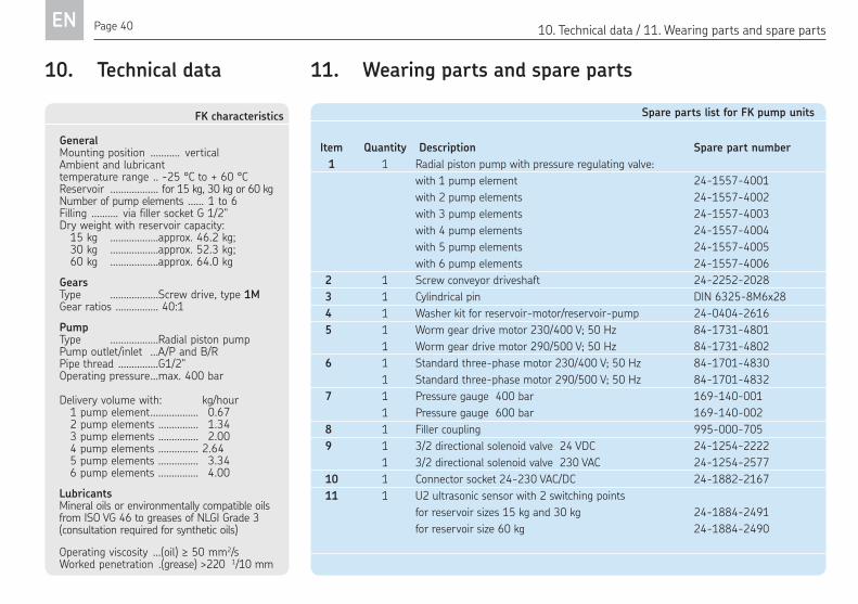
10. Technical data
FK characteristics
GeneralMounting position ........... verticalAmbient and lubricanttemperature range .. -25 °C to + 60 °CReservoir .................. for 15 kg, 30 kg or 60 kgNumber of pump elements ...... 1 to 6 Filling .......... via filler socket G 1/2" Dry weight with reservoir capacity: 15 kg ..................approx. 46.2 kg; 30 kg ..................approx. 52.3 kg; 60 kg ..................approx. 64.0 kg
Gears Type ..................Screw drive, type 1MGear ratios ................ 40:1
Pump Type ..................Radial piston pumpPump outlet/inlet ...A/P and B/RPipe thread ...............G1/2" Operating pressure ...max. 400 bar
Delivery volume with: kg/hour 1 pump element .................. 0.67 2 pump elements ............... 1.34 3 pump elements ............... 2.00 4 pump elements ............... 2.64 5 pump elements ............... 3.34 6 pump elements ............... 4.00
LubricantsMineral oils or environmentally compatible oils from ISO VG 46 to greases of NLGI Grade 3 (consultation required for synthetic oils)
Operating viscosity ...(oil) ≥ 50 mm2/sWorked penetration .(grease) >220 1/10 mm
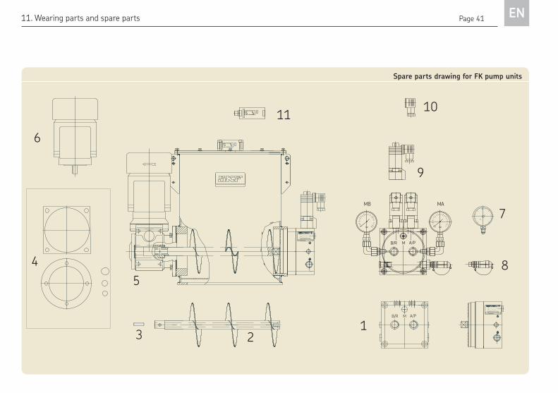
11. Wearing parts and spare parts
Spare parts list for FK pump units
Item Quantity Description Spare part number
1 1 Radial piston pump with pressure regulating valve:
with 1 pump element 24-1557-4001
with 2 pump elements 24-1557-4002
with 3 pump elements 24-1557-4003
with 4 pump elements 24-1557-4004
with 5 pump elements 24-1557-4005
with 6 pump elements 24-1557-4006
2 1 Screw conveyor driveshaft 24-2252-2028
3 1 Cylindrical pin DIN 6325-8M6x28
4 1 Washer kit for reservoir-motor/reservoir-pump 24-0404-2616
5 1 Worm gear drive motor 230/400 V; 50 Hz 84-1731-4801
1 Worm gear drive motor 290/500 V; 50 Hz 84-1731-4802
6 1 Standard three-phase motor 230/400 V; 50 Hz 84-1701-4830
1 Standard three-phase motor 290/500 V; 50 Hz 84-1701-4832
7 1 Pressure gauge 400 bar 169-140-001
1 Pressure gauge 600 bar 169-140-002
8 1 Filler coupling 995-000-705
9 1 3/2 directional solenoid valve 24 VDC 24-1254-2222
1 3/2 directional solenoid valve 230 VAC 24-1254-2577
10 1 Connector socket 24-230 VAC/DC 24-1882-2167
11 1 U2 ultrasonic sensor with 2 switching points
for reservoir sizes 15 kg and 30 kg 24-1884-2491
for reservoir size 60 kg 24-1884-2490
Page 41 EN11. Wearing parts and spare parts
123
6
7
58
9
1011
4
AB
TEACH-IN
MODE
AA
TEACH-IN
AB
MODE
AA
Made in Germany
...................
R
Made in Germany
...................
R
FK..................................
Grease/Fett NLGI-2 max.774-...........................
MB
bar
A/PB/R M
bar
MA
FK..................................
Grease/Fett NLGI-2 max.774-...........................
B/R M A/P
Spare parts drawing for FK pump units

Page 42 EN
Information on EC Directives
Note
You may request the original Manu-facturer’s Declaration/Declaration of Incorporation for this product from our central contact address if needed.
EC Directives
Conformity assessment
Information on conformity assessment
We hereby conirm that a Declaration of Conformity was produced for grease lubrica-
tion pump units of the FK series in the course
of product development/product release. This Declaration is included in the machine ile for the FK series.

Page 43 EN

SKF Lubrication Systems Germany GmbH
2. Industriestraße 4 · 68766 Hockenheim · Germany
Tel. +49 (0)62 05 27-0 · Fax +49 (0)62 05 27-101
www.skf.com/lubrication
SKF Lubrication Systems Germany GmbH
Motzener Strasse 35/37 · 12277 Berlin · Germany
PF 970444 · 12704 Berlin · Germany
Tel. +49 (0)30 72002-0 · Fax +49 (0)30 72002-111
www.skf.com/lubrication
951-170-200-EN
The contents of this publication are the copyright of the publisher and may not be re-produced in whole or in part without permission of SKF Lubrication Systems Germany GmbH. Every care has been taken to ensure the accuracy of the information contained in this publication. However, no liability can be accepted for any loss or damage, whether direct, indirect or consequential arising out of use of the information con-tained herein. All SKF products may be used only for their intended purpose as described in these assembly instructions with associated operating instructions. If assembly/operating in-structions are supplied together with the products, they must be read and followed. Not all lubricants can be fed using centralized lubrication systems. SKF can, on re-quest, inspect the feedability of the lubricant selected by the user in centralized lubri-cation systems. Lubrication systems and their components manufactured by SKF are not approved for use in conjunction with gases, liquefied gases, pressurized gases in solution, vapors or such fluids whose vapor pressure exceeds normal atmospheric pres-sure (1013 mbar) by more than 0.5 bar at their maximum permissible temperature. Hazardous materials of any kind, especially the materials classified as hazardous by CLP Regulation EC 1272/2008 may only be used to fill SKF centralized lubrication sys-tems and components and deliv-ered and/or distributed with the same after consulting with and receiving written approval from SKF.