Five-axis pencil-cut planning and virtual prototyping
with 5-DOF haptic interface
Weihang Zhu, Yuan-Shin Lee*
Department of Industrial Engineering, North Carolina State University, Raleigh, NC 27695-7906, USA
Received 22 August 2003; received in revised form 22 January 2004; accepted 30 January 2004
Abstract
In this paper, techniques of 5-axis pencil-cut machining planning with a 5-DOF (degree of freedom) output haptic interface are presented.
Detailed techniques of haptic rendering and tool interference avoidance are discussed for haptic-aided 5-axis pencil-cut tool path generation.
Five-axis tool path planning has attracted great attention in CAD/CAM and NC machining. For efficient machining of complex surfaces,
pencil-cut uses relatively smaller tools to remove the remaining material at corners or highly curved regions that are inaccessible with larger
tools. As a critical problem for 5-axis pencil-cut tool path planning, the tasks of tool orientation determination and tool collision avoidance
are achieved with a developed 5-DOF haptic interface. A Two-phase rendering approach is proposed for haptic rendering and force-torque
feedback calculation with haptic interface. A Dexel-based volume modeling method is developed for global tool interference avoidance with
surrounding components in a 5-axis machining environment. Hardware and software implementation of the haptic pencil-cut system
with practical examples are also presented in this paper. The presented technique can be used for CAD/CAM, 5-axis machining planning and
virtual prototyping.
q 2004 Elsevier Ltd. All rights reserved.
Keywords: 5-axis machining; Pencil-cut planning; Haptic rendering; CAD/CAM; NC machining; Virtual prototyping
1. Introduction
Five-axis tool path planning has attracted great attention
in Computer-aided Manufacturing (CAM) and NC
machining. Many issues of 5-axis machining need to be
addressed; among them the tool path generation and tool
orientation control are two main issues. Great progress has
been made in 5-axis tool path planning after years of
research [1–3]. While continuing work is being pursued to
improve 5-axis tool path planning, haptic interface has
gradually aroused the interest of the Computer-aided Design/
Computer-aided Manufacturing (CAD/CAM) research area.
Haptics is concerned with information and object manipu-
lation through touch. Besides transducing position and
motion commands from the user, the haptic devices can
present controlled forces to the user, allowing him or her to
feel virtual objects and to control or deform the objects [4].
Haptic interface has found its applications in design,
medicine, entertainment, education, industry, graphic arts,
etc [5]. In this paper, we are especially interested in the haptic
application in CAD/CAM and NC machining.
In the CAD area, researchers from University of Utah
have published their work on direct manipulating of
NURBS surface with their special haptic manipulator [6].
Basically, it is a system wherein one can trace along a
NURBS surface and feel it. A dynamic sculpting system for
free-form subdivision solids was developed at SUNY Stony
Brook [7]. A virtual carving system with a commercial
haptic interface was developed at University of Missouri-
Rolla [8]. These presented systems, although different in
their implementations and some underlying theories, can
both be traced back to volume sculpting [9].
In the CAM area, some initial attempts and inspiring
work have been developed at MIT. Researchers have
produced some interesting results in 5-axis tool path
generation. In their work, a quick collision detection
method was proposed between a tool and a machining
environment represented by point clouds [10]. In their tool
path generation application, they machined a part with a
constant Z-height machining method [11]. In our earlier
work presented in Ref. [12,13], techniques of haptic virtual
sculpting of complex surfaces have been developed.
0010-4485/$ - see front matter q 2004 Elsevier Ltd. All rights reserved.
doi:10.1016/j.cad.2004.01.013
Computer-Aided Design 36 (2004) 1295–1307
www.elsevier.com/locate/cad
* Corresponding author. Tel.: þ1-919-515-7195; fax: þ1-919-515-5281.
E-mail address: [email protected] (Y.-S. Lee).

This paper presents the techniques of employing
haptic interface for 5-axis pencil-cut tool path planning. A
lab-built 5-DOF (degree of freedom) haptic device, haptic
hardware controller and haptic rendering software are
developed. The remainder of this paper is organized as
follows. Section 2 introduces the problem of pencil-cut
machining operation. Section 3 describes the methodology
of the haptic-aided 5-axis pencil-cut tool path generation in
details. Section 4 discusses the software and hardware issues
in implementing the haptic interface system. Practical
examples and experiment results are presented in
Section 5, followed by concluding remarks and future work.
2. Problems of pencil-cut machining
of sculptured surfaces
In sculptured surface machining, the several stages of
machining include roughing, semi-finishing, finishing and
clean-up [1]. Roughing removes the bulk material outside
the design surface. After semi-finishing and finishing,
the shape of the machined surface is very close to the
designed part surface. Clean-up machining removes the
remaining material left at the sharp corners or edges.
Pencil-cut is used for clean-up machining (Fig. 1(a)).
Pencil-cut in 3-axis machining has been researched for
years, and this function is provided in some commercial
software for parametric surfaces. In our earlier work
presented in Ref. [14], algorithms for 3-axis pencil-cut of
polyhedral models have been developed for sculptured
surface machining. To the best of our knowledge, research
work on 5-axis pencil-cut has not been reported.
Five-axis pencil-cut has the obvious advantage over
3-axis pencil-cut, due to the former’s better accessibility
with the additional rotation axes. For 3-axis pencil-cut,
the tool orientation is fixed as the Z-axis, as shown in
Fig. 1(a). Five-axis pencil-cut is especially useful for
cleaning remaining materials in complex surfaces. As can
be seen from Fig. 1(b), the curved corner region can be
accessed by 5-axis machining but is not accessible by 3-axis
machining. In our earlier work presented in Ref. [14],
a method has been developed to identify the clean-up
regions on complex part surfaces. For 5-axis pencil-cut,
the difficulty for tool path planning lies mostly in
determining the tool orientation.
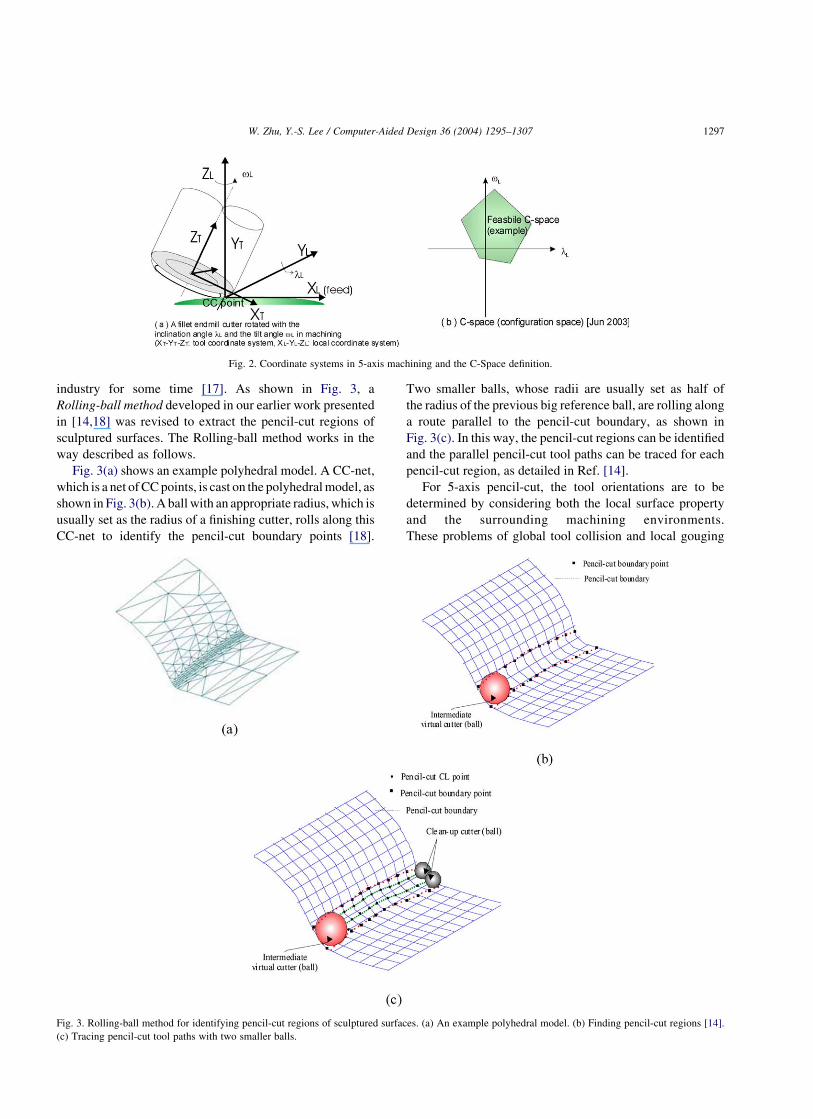
In 5-axis machining, a cutting tool can be oriented by
rotating around one axis with an inclination angle lL and
another axis with a tilt angle vL; as shown in Fig. 2.
To facilitate searching for a feasible tool orientation, usually
a local coordinate system is set up as follows: XL-axis is the
instantaneous feed direction (cutting direction); ZL-axis is
the surface normal direction at the current cutter contact
(CC) point; YL-axis is determined by the right-hand rule
(Fig. 2(a)) [3]. Then the tool orientations are searched based
on this local coordinate system. To find a good tool
orientation control in 5-axis machining, a configuration-
space (C-space) is formed with the inclination angle lL and
the tilt angle vL; as shown in Fig. 2(b) [1]. As discussed in
Ref. [2], a machining C-space MCS of a given CC point CCi
on a designed part surface, PS, machined with a cutter C can
be defined as follows (also see Fig. 2(b))
MCSðC; PS; {CCi}Þi¼0;…;n ¼lL
vL
" #ð1Þ
Past research on the tool orientation mainly adjusts the
inclination angle lL; due to the theoretically infinite
combinations of inclination angle lL and tilt angle vL:
Most of the research considers only the local optimal tool
orientation, which is based on analysis of the part surface
property and cutting conditions near the CC point.
When seeking the globally optimized tool orientation in
5-axis machining, we have to deal with expensive
computation and searching concerning the interference
between the whole tool assembly and the stock. The reason
is that we have to find the feasible (not necessarily the
optimal) tool orientation by trial and error. Several attempts
were made in circumventing this exhaustive search [15,16].
However, there are also some limitations in the results, due
to the different assumptions made about the designed part
surface or the cutting tool [2].
In this paper, we developed a haptic system to help
determine and select the tool orientations for 5-axis
pencil-cut machining in a complex machining environment
[13]. Details of developing the haptic system are discussed
in the following sections.
3. Proposed haptic system for 5-axis pencil-cutmachining
3.1. Identification of pencil-cut region and tool
path generation
The first step for pencil-cut machining is to identify
where the pencil-cut operation should be executed. In this
paper, a designed surface is represented in stereo
lithography (STL) format, which is composed of a
collection of triangles and basically is a kind of polyhedral
model (see Fig. 3(a)). The use of STL format for
representing a CAD model has been widely accepted inFig. 1. Pencil-cut of complex surfaces. (a) Three-axis pencil-cut. (b) Five-
axis pencil-cut.
W. Zhu, Y.-S. Lee / Computer-Aided Design 36 (2004) 1295–13071296
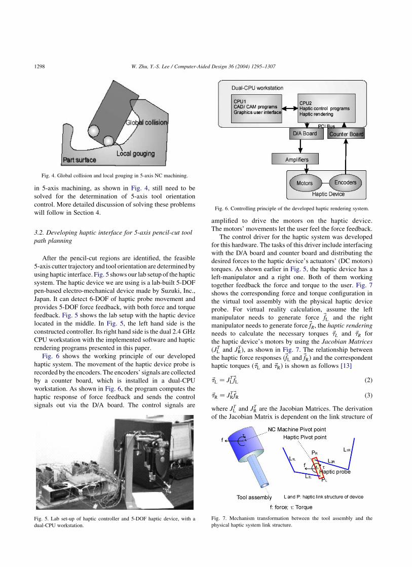
industry for some time [17]. As shown in Fig. 3, a
Rolling-ball method developed in our earlier work presented
in [14,18] was revised to extract the pencil-cut regions of
sculptured surfaces. The Rolling-ball method works in the
way described as follows.
Fig. 3(a) shows an example polyhedral model. A CC-net,
which is a net of CC points, is cast on the polyhedral model, as
shown in Fig. 3(b). A ball with an appropriate radius, which is
usually set as the radius of a finishing cutter, rolls along this
CC-net to identify the pencil-cut boundary points [18].
Two smaller balls, whose radii are usually set as half of
the radius of the previous big reference ball, are rolling along
a route parallel to the pencil-cut boundary, as shown in
Fig. 3(c). In this way, the pencil-cut regions can be identified
and the parallel pencil-cut tool paths can be traced for each
pencil-cut region, as detailed in Ref. [14].
For 5-axis pencil-cut, the tool orientations are to be
determined by considering both the local surface property
and the surrounding machining environments.
These problems of global tool collision and local gouging
Fig. 2. Coordinate systems in 5-axis machining and the C-Space definition.
Fig. 3. Rolling-ball method for identifying pencil-cut regions of sculptured surfaces. (a) An example polyhedral model. (b) Finding pencil-cut regions [14].
(c) Tracing pencil-cut tool paths with two smaller balls.
W. Zhu, Y.-S. Lee / Computer-Aided Design 36 (2004) 1295–1307 1297
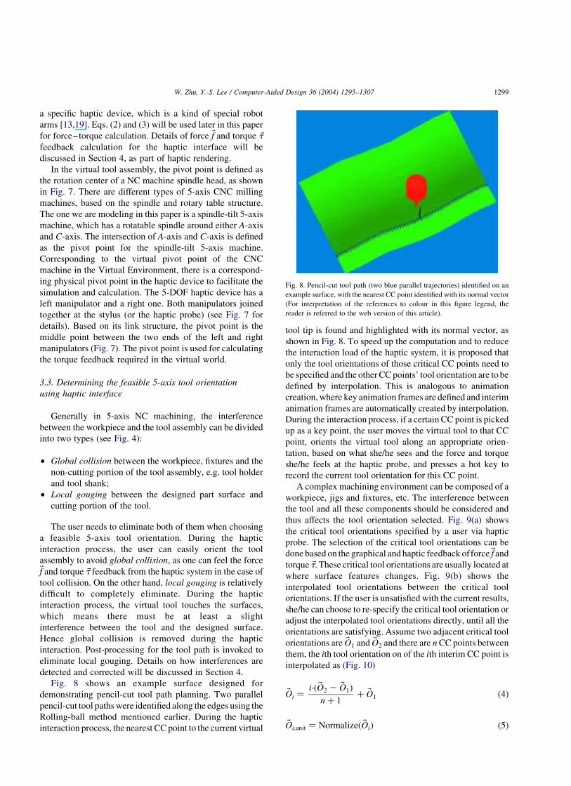
in 5-axis machining, as shown in Fig. 4, still need to be
solved for the determination of 5-axis tool orientation
control. More detailed discussion of solving these problems
will follow in Section 4.
3.2. Developing haptic interface for 5-axis pencil-cut tool
path planning
After the pencil-cut regions are identified, the feasible
5-axis cutter trajectory and tool orientation are determined by
using haptic interface. Fig. 5 shows our lab setup of the haptic
system. The haptic device we are using is a lab-built 5-DOF
pen-based electro-mechanical device made by Suzuki, Inc.,
Japan. It can detect 6-DOF of haptic probe movement and
provides 5-DOF force feedback, with both force and torque
feedback. Fig. 5 shows the lab setup with the haptic device
located in the middle. In Fig. 5, the left hand side is the
constructed controller. Its right hand side is the dual 2.4 GHz
CPU workstation with the implemented software and haptic
rendering programs presented in this paper.
Fig. 6 shows the working principle of our developed
haptic system. The movement of the haptic device probe is
recorded by the encoders. The encoders’ signals are collected
by a counter board, which is installed in a dual-CPU
workstation. As shown in Fig. 6, the program computes the
haptic response of force feedback and sends the control
signals out via the D/A board. The control signals are
amplified to drive the motors on the haptic device.
The motors’ movements let the user feel the force feedback.
The control driver for the haptic system was developed
for this hardware. The tasks of this driver include interfacing
with the D/A board and counter board and distributing the
desired forces to the haptic device’s actuators’ (DC motors)
torques. As shown earlier in Fig. 5, the haptic device has a
left-manipulator and a right one. Both of them working
together feedback the force and torque to the user. Fig. 7
shows the corresponding force and torque configuration in
the virtual tool assembly with the physical haptic device
probe. For virtual reality calculation, assume the left
manipulator needs to generate force ~fL and the right
manipulator needs to generate force ~fR; the haptic rendering
needs to calculate the necessary torques ~tL and ~tR for
the haptic device’s motors by using the Jacobian Matrices
(JTL and JT
R), as shown in Fig. 7. The relationship between
the haptic force responses (~fL and ~fR) and the correspondent
haptic torques ( ~tL and ~tR) is shown as follows [13]
~tL ¼ JTL~fL ð2Þ
~tR ¼ JTR~fR ð3Þ
where JTL and JT
R are the Jacobian Matrices. The derivation
of the Jacobian Matrix is dependent on the link structure of
Fig. 4. Global collision and local gouging in 5-axis NC machining.
Fig. 5. Lab set-up of haptic controller and 5-DOF haptic device, with a
dual-CPU workstation.
Fig. 6. Controlling principle of the developed haptic rendering system.
Fig. 7. Mechanism transformation between the tool assembly and the
physical haptic system link structure.
W. Zhu, Y.-S. Lee / Computer-Aided Design 36 (2004) 1295–13071298
a specific haptic device, which is a kind of special robot
arms [13,19]. Eqs. (2) and (3) will be used later in this paper
for force–torque calculation. Details of force ~f and torque ~t
feedback calculation for the haptic interface will be
discussed in Section 4, as part of haptic rendering.
In the virtual tool assembly, the pivot point is defined as
the rotation center of a NC machine spindle head, as shown
in Fig. 7. There are different types of 5-axis CNC milling
machines, based on the spindle and rotary table structure.
The one we are modeling in this paper is a spindle-tilt 5-axis
machine, which has a rotatable spindle around either A-axis
and C-axis. The intersection of A-axis and C-axis is defined
as the pivot point for the spindle-tilt 5-axis machine.
Corresponding to the virtual pivot point of the CNC
machine in the Virtual Environment, there is a correspond-
ing physical pivot point in the haptic device to facilitate the
simulation and calculation. The 5-DOF haptic device has a
left manipulator and a right one. Both manipulators joined
together at the stylus (or the haptic probe) (see Fig. 7 for
details). Based on its link structure, the pivot point is the
middle point between the two ends of the left and right
manipulators (Fig. 7). The pivot point is used for calculating
the torque feedback required in the virtual world.
3.3. Determining the feasible 5-axis tool orientation
using haptic interface
Generally in 5-axis NC machining, the interference
between the workpiece and the tool assembly can be divided
into two types (see Fig. 4):
† Global collision between the workpiece, fixtures and the
non-cutting portion of the tool assembly, e.g. tool holder
and tool shank;
† Local gouging between the designed part surface and
cutting portion of the tool.
The user needs to eliminate both of them when choosing
a feasible 5-axis tool orientation. During the haptic
interaction process, the user can easily orient the tool
assembly to avoid global collision, as one can feel the force~f and torque ~t feedback from the haptic system in the case of
tool collision. On the other hand, local gouging is relatively
difficult to completely eliminate. During the haptic
interaction process, the virtual tool touches the surfaces,
which means there must be at least a slight
interference between the tool and the designed surface.
Hence global collision is removed during the haptic
interaction. Post-processing for the tool path is invoked to
eliminate local gouging. Details on how interferences are
detected and corrected will be discussed in Section 4.
Fig. 8 shows an example surface designed for
demonstrating pencil-cut tool path planning. Two parallel
pencil-cut tool paths were identified along the edges using the
Rolling-ball method mentioned earlier. During the haptic
interaction process, the nearest CC point to the current virtual
tool tip is found and highlighted with its normal vector, as
shown in Fig. 8. To speed up the computation and to reduce
the interaction load of the haptic system, it is proposed that
only the tool orientations of those critical CC points need to
be specified and the other CC points’ tool orientation are to be
defined by interpolation. This is analogous to animation
creation, where key animation frames are defined and interim
animation frames are automatically created by interpolation.
During the interaction process, if a certain CC point is picked
up as a key point, the user moves the virtual tool to that CC
point, orients the virtual tool along an appropriate orien-
tation, based on what she/he sees and the force and torque
she/he feels at the haptic probe, and presses a hot key to
record the current tool orientation for this CC point.
A complex machining environment can be composed of a
workpiece, jigs and fixtures, etc. The interference between
the tool and all these components should be considered and
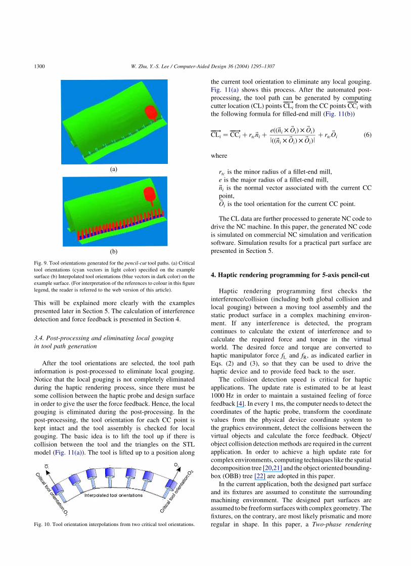
thus affects the tool orientation selected. Fig. 9(a) shows
the critical tool orientations specified by a user via haptic
probe. The selection of the critical tool orientations can be
done based on the graphical and haptic feedback offorce ~f and
torque ~t:These critical tool orientations are usually located at
where surface features changes. Fig. 9(b) shows the
interpolated tool orientations between the critical tool
orientations. If the user is unsatisfied with the current results,
she/he can choose to re-specify the critical tool orientation or
adjust the interpolated tool orientations directly, until all the
orientations are satisfying. Assume two adjacent critical tool
orientations are ~O1 and ~O2 and there are n CC points between
them, the ith tool orientation on of the ith interim CC point is
interpolated as (Fig. 10)
~Oi ¼i·ð ~O2 2 ~O1Þ
n þ 1þ ~O1 ð4Þ
~Oi;unit ¼ Normalizeð ~OiÞ ð5Þ
Fig. 8. Pencil-cut tool path (two blue parallel trajectories) identified on an
example surface, with the nearest CC point identified with its normal vector
(For interpretation of the references to colour in this figure legend, the
reader is referred to the web version of this article).
W. Zhu, Y.-S. Lee / Computer-Aided Design 36 (2004) 1295–1307 1299
This will be explained more clearly with the examples
presented later in Section 5. The calculation of interference
detection and force feedback is presented in Section 4.
3.4. Post-processing and eliminating local gouging
in tool path generation
After the tool orientations are selected, the tool path
information is post-processed to eliminate local gouging.
Notice that the local gouging is not completely eliminated
during the haptic rendering process, since there must be
some collision between the haptic probe and design surface
in order to give the user the force feedback. Hence, the local
gouging is eliminated during the post-processing. In the
post-processing, the tool orientation for each CC point is
kept intact and the tool assembly is checked for local
gouging. The basic idea is to lift the tool up if there is
collision between the tool and the triangles on the STL
model (Fig. 11(a)). The tool is lifted up to a position along
the current tool orientation to eliminate any local gouging.
Fig. 11(a) shows this process. After the automated post-
processing, the tool path can be generated by computing
cutter location (CL) points CLi��!
from the CC points CCi��!
with
the following formula for filled-end mill (Fig. 11(b))
CLi��!
¼ CCi��!
þ rtc~ni þeðð~ni £ ~OiÞ £ ~OiÞ
lðð~ni £ ~OiÞ £ ~OiÞlþ rtc
~Oi ð6Þ
where
rtc is the minor radius of a fillet-end mill,
e is the major radius of a fillet-end mill,
~ni is the normal vector associated with the current CC
point,~Oi is the tool orientation for the current CC point.
The CL data are further processed to generate NC code to
drive the NC machine. In this paper, the generated NC code
is simulated on commercial NC simulation and verification
software. Simulation results for a practical part surface are
presented in Section 5.
4. Haptic rendering programming for 5-axis pencil-cut
Haptic rendering programming first checks the
interference/collision (including both global collision and
local gouging) between a moving tool assembly and the
static product surface in a complex machining environ-
ment. If any interference is detected, the program
continues to calculate the extent of interference and to
calculate the required force and torque in the virtual
world. The desired force and torque are converted to
haptic manipulator force fL and fR; as indicated earlier in
Eqs. (2) and (3), so that they can be used to drive the
haptic device and to provide feed back to the user.
The collision detection speed is critical for haptic
applications. The update rate is estimated to be at least
1000 Hz in order to maintain a sustained feeling of force
feedback [4]. In every 1 ms, the computer needs to detect the
coordinates of the haptic probe, transform the coordinate
values from the physical device coordinate system to
the graphics environment, detect the collisions between the
virtual objects and calculate the force feedback. Object/
object collision detection methods are required in the current
application. In order to achieve a high update rate for
complex environments, computing techniques like the spatial
decomposition tree [20,21] and the object oriented bounding-
box (OBB) tree [22] are adopted in this paper.
In the current application, both the designed part surface
and its fixtures are assumed to constitute the surrounding
machining environment. The designed part surfaces are
assumed to be freeform surfaces with complex geometry. The
fixtures, on the contrary, are most likely prismatic and more
regular in shape. In this paper, a Two-phase rendering
Fig. 9. Tool orientations generated for the pencil-cut tool paths. (a) Critical
tool orientations (cyan vectors in light color) specified on the example
surface (b) Interpolated tool orientations (blue vectors in dark color) on the
example surface. (For interpretation of the references to colour in this figure
legend, the reader is referred to the web version of this article).
Fig. 10. Tool orientation interpolations from two critical tool orientations.
W. Zhu, Y.-S. Lee / Computer-Aided Design 36 (2004) 1295–13071300

approach to tool collision detection and local gouging
elimination is proposed for haptic pencil-cut of sculptured
surfaces. A Dexel-based volume modeling method is used for
global tool interference avoidance with surrounding com-
ponents, such as fixtures or tables, of a machining environ-
ment. Both approaches are detailed in the following sections.
4.1. Two-phase rendering approach to collision detection
and force response
In this paper, a Two-phase rendering approach is
proposed for the haptic pencil-cut interface and the
rendering programming, as shown in Fig. 12. In the Two-
phase approach, for the convenience of the first phase, the
triangular polygons in STL models are organized into OBB
trees, as shown in the ‘First phase’ of Fig. 13.
In the first phase (see Figs. 12 and 13), the possible
collision triangles (PCT) are extracted by checking the
interference between the OBB-trees of STL surface models
and the simple OBB-tree of the tool assembly. In our
approach, the tool definition is a combination of implicit
surfaces. To improve the computing efficiency, we try to
simplify the definition of the tool while trying to
accommodate a more complex part surface. A triangulated
STL model is adopted in this paper because the computation
and geometric processing of the STL model are relatively
faster. The next step is to find out how we can quickly detect
the collision and calculate the force feedback. The STL
surface model’s OBB-tree is static during the interaction
process. During the movement of the haptic probe, the tool
assembly’s OBB-tree is updated (Fig. 13). There is little
overhead in updating the tool assembly’s OBB-tree.
In the second phase (Figs. 12 and 13), to improve the
efficiency of collision detection, the triangles in the STL
model are discretized into sampling point clouds at the
beginning of the haptic application, as shown in the
‘Second phase’ in Fig. 13. Each point is associated with a
normal direction, which is set as the normal direction of the
triangle it belongs to. Adaptive point cloud density is used
for different features of the tool assembly. In the second
phase, the points corresponding to the PCT are checked
against the tool’s implicit surface for the collision test, as
shown in Fig. 12. If a point is inside the tool assembly,
we find the tool surface point nearest the collision point and
then calculate the distance between the collision point
and the corresponding tool surface point. The force
magnitude is proportional to this distance. Assuming this
distance is Dxi and k is a pre-defined coefficient, the
responding force magnitude fi;mag is calculated as follows
fi;mag ¼ kDxi ð7Þ
The unit force direction ~fi;dir has already been associated
with the collision point, as mentioned earlier in the process
of generating point cloud. A component force ~fiðfi;mag;~fi;dirÞ
is determined by its magnitude fi;mag and direction ~fi;dir: If we
assume that the virtual pivot point’s location is Ppvt;
the collision point’s location is Pi; and the force magnitude
of fi;mag is calculated by Eq. (7), the torque ti induced by this
Fig. 11. Computing CL points from CC Points. (a) Retracting cutter to avoid local gouging; (b) computing CL point from CC point.
Fig. 12. Two-phase approach for haptic rendering.
W. Zhu, Y.-S. Lee / Computer-Aided Design 36 (2004) 1295–1307 1301
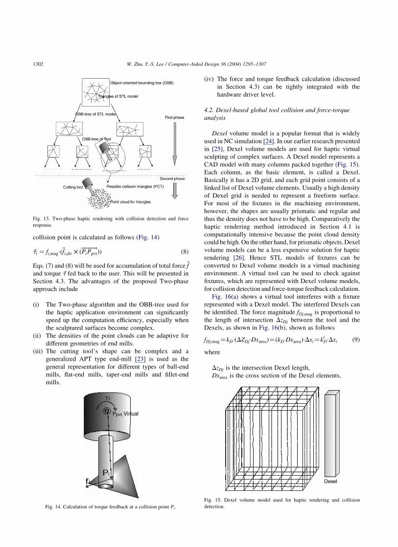
collision point is calculated as follows (Fig. 14)
~ti ¼ fi;mag·ð~fi;dir £ ðPiPpvt����!
ÞÞ ð8Þ
Eqs. (7) and (8) will be used for accumulation of total force ~f
and torque ~t fed back to the user. This will be presented in
Section 4.3. The advantages of the proposed Two-phase
approach include
(i) The Two-phase algorithm and the OBB-tree used for
the haptic application environment can significantly
speed up the computation efficiency, especially when
the sculptured surfaces become complex.
(ii) The densities of the point clouds can be adaptive for
different geometries of end mills.
(iii) The cutting tool’s shape can be complex and a
generalized APT type end-mill [23] is used as the
general representation for different types of ball-end
mills, flat-end mills, taper-end mills and fillet-end
mills.
(iv) The force and torque feedback calculation (discussed
in Section 4.3) can be tightly integrated with the
hardware driver level.
4.2. Dexel-based global tool collision and force-torque
analysis
Dexel volume model is a popular format that is widely
used in NC simulation [24]. In our earlier research presented
in [25], Dexel volume models are used for haptic virtual
sculpting of complex surfaces. A Dexel model represents a
CAD model with many columns packed together (Fig. 15).
Each column, as the basic element, is called a Dexel.
Basically it has a 2D grid, and each grid point consists of a
linked list of Dexel volume elements. Usually a high density
of Dexel grid is needed to represent a freeform surface.
For most of the fixtures in the machining environment,
however, the shapes are usually prismatic and regular and
thus the density does not have to be high. Comparatively the
haptic rendering method introduced in Section 4.1 is
computationally intensive because the point cloud density
could be high. On the other hand, for prismatic objects, Dexel
volume models can be a less expensive solution for haptic
rendering [26]. Hence STL models of fixtures can be
converted to Dexel volume models in a virtual machining
environment. A virtual tool can be used to check against
fixtures, which are represented with Dexel volume models,
for collision detection and force-torque feedback calculation.
Fig. 16(a) shows a virtual tool interferes with a fixture
represented with a Dexel model. The interfered Dexels can
be identified. The force magnitude fDj;mag is proportional to
the length of intersection DzDj between the tool and the
Dexels, as shown in Fig. 16(b), shown as follows
fDj;mag¼kD·ðDZDj·DxareaÞ¼ðkD·DxareaÞ·Dxi¼k0D·Dxi ð9Þ
where
DzDj is the intersection Dexel length,
Dxarea is the cross section of the Dexel elements,
Fig. 13. Two-phase haptic rendering with collision detection and force
response.
Fig. 14. Calculation of torque feedback at a collision point Pi:
Fig. 15. Dexel volume model used for haptic rendering and collision
detection.
W. Zhu, Y.-S. Lee / Computer-Aided Design 36 (2004) 1295–13071302

kD is the pre-defined cross-section dependent force
coefficient,
k0D is the cross-section independent force coefficient.
Now the force direction ~fDj;dir needs to be defined.
As shown in Fig. 16(b), the whole cutter assembly is
considered to be composed of two portions: holder and cutter.
The geometric center of the holder and cutter portions can be
defined, respectively, as Pholder_center and Pcutter_center:The tool
assembly may be intersected with the Dexel model of the
holder or cutter portion. Assuming that the geometric enter of
the intersected dexel element is PD;mid; the force direction~fDj;dir is defined as follows (Fig. 16(b))
~fDj;dir ¼PD;midPholder_center�������������!
; for holder portion
PD;midPcutter_center������������!
; for cutter portion
8<: ð10Þ
A component force ~fDjðfDj;mag;~fDj;dirÞ is determined by its
magnitude fDj;mag and direction ~fDj;dir: Assuming that the
virtual pivot point’s location is Ppvt; the center location of the
intersected Dexel is PDj; and the force magnitude of fDj;mag is
calculated with Eq. (9), the torque tDj induced by this
collision point is calculated as follows (Fig. 16(b))
~tDj ¼ fDj;mag·ð~fDj;dir £ ðPDjPpvt�����!
ÞÞ ð11Þ
The collision force ~fDjðfDj;mag;~fDj;dirÞ and the correspondent
torque ~tDj found by using Eqs. (9)–(11) are used in the haptic
rendering to provide force–torque feedback to the users.
Details are discussed in Section 4.3.
4.3. Force and torque feedback distribution to the haptic
device hardware
For the force–torque feedback on the haptic device during
pencil-cut of the complex surfaces, two types of force–tor-
ques need to be considered. These two types of force–torque
feedbacks need to be distinguished in the haptic rendering:
1. Tracing force. As the tool moves on the surface and traces
along the tool path, the force feedback is the tracing force
and the force–torque (~fi and ~ti) feedback is calculated by
using Eqs. (7) and (8).
2. Collision force. If the tool holderof the tool system collides
withpart surface(ie.~fi and ~ti usingEqs. (7)and(8)),or if the
tool collides with the fixtures in the machining environ-
ment (i.e. ~fDj and ~tDj using Eqs. (9)–(11)), the force
feedback is classified as the collision force. The force–
torque feedback can be calculated by using Eqs. (7)–(11).
In general, the collision force is relatively strong
compared to the tracing force. Assuming that there are a
total of m collision points and q Dexel intersections in the
current instance, from Eqs. (7)–(11), the force ~f and torque ~t
feedback via the haptic probe can be calculated as follows:
~f¼Xmi¼1
~fiþXq
j¼1
~fDj¼kXmi¼1
ðDxi·~fi;dirÞþk0DXq
j¼1
ðDzDj·~fDj;dirÞ ð12Þ
~t¼Xmi¼1
~tiþXq
j¼1
~tj¼kXmi¼1
ðDxi·ð~fi;dir£ðPiPpvt����!
ÞÞÞ
þk0DXq
j¼1
ðDzDj·ð~fDj;dir£ðPDjPpvt�����!
ÞÞÞ ð13Þ
Force ~f is distributed to two manipulators as follows
(Fig. 17)
~fLf ¼ f =2 ð14Þ
~fRf ¼ f =2 ð15Þ
In both Figs. 7 and 17, if we assume that the vector from the
left haptic manipulator end PL to right manipulator end PR is
~rLR; the torque is distributed to two manipulators as follows
~fLt¼~t
l~rLRl·~t£~rLR
l ~t£~rLRl¼2~fRt ð16Þ
Then the desired forces on the left and right manipulators are
calculated as follows
~fL¼~fLf þ~fLt ð17Þ
~fR¼~fRf þ~fRt ð18Þ
The desired forces ~fL and ~fR are then substituted into Eqs. (2)
and (3) to get the corresponding DC motor torques ~tL and ~tR:
The rotation of the DC motors applies force on the user’s
hand through the haptic device structure.
Fig. 16. Calculation of force–torque feedbacks using Dexel volume models.
(a) A virtual tool collision with a Dexel volume model. (b) Calculation of
torque feedback with collision points PDi in the Dexel volume model.
W. Zhu, Y.-S. Lee / Computer-Aided Design 36 (2004) 1295–1307 1303
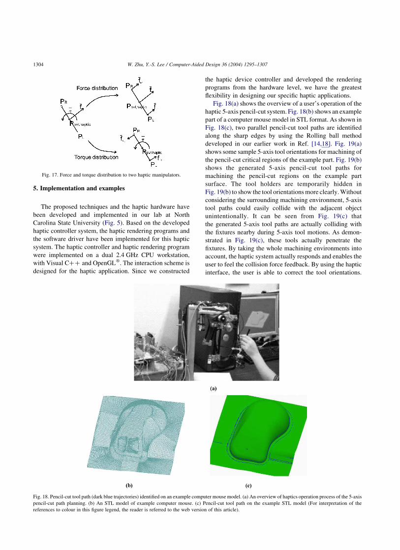
5. Implementation and examples
The proposed techniques and the haptic hardware have
been developed and implemented in our lab at North
Carolina State University (Fig. 5). Based on the developed
haptic controller system, the haptic rendering programs and
the software driver have been implemented for this haptic
system. The haptic controller and haptic rendering program
were implemented on a dual 2.4 GHz CPU workstation,
with Visual Cþþ and OpenGLw. The interaction scheme is
designed for the haptic application. Since we constructed
the haptic device controller and developed the rendering
programs from the hardware level, we have the greatest
flexibility in designing our specific haptic applications.
Fig. 18(a) shows the overview of a user’s operation of the
haptic 5-axis pencil-cut system. Fig. 18(b) shows an example
part of a computer mouse model in STL format. As shown in
Fig. 18(c), two parallel pencil-cut tool paths are identified
along the sharp edges by using the Rolling ball method
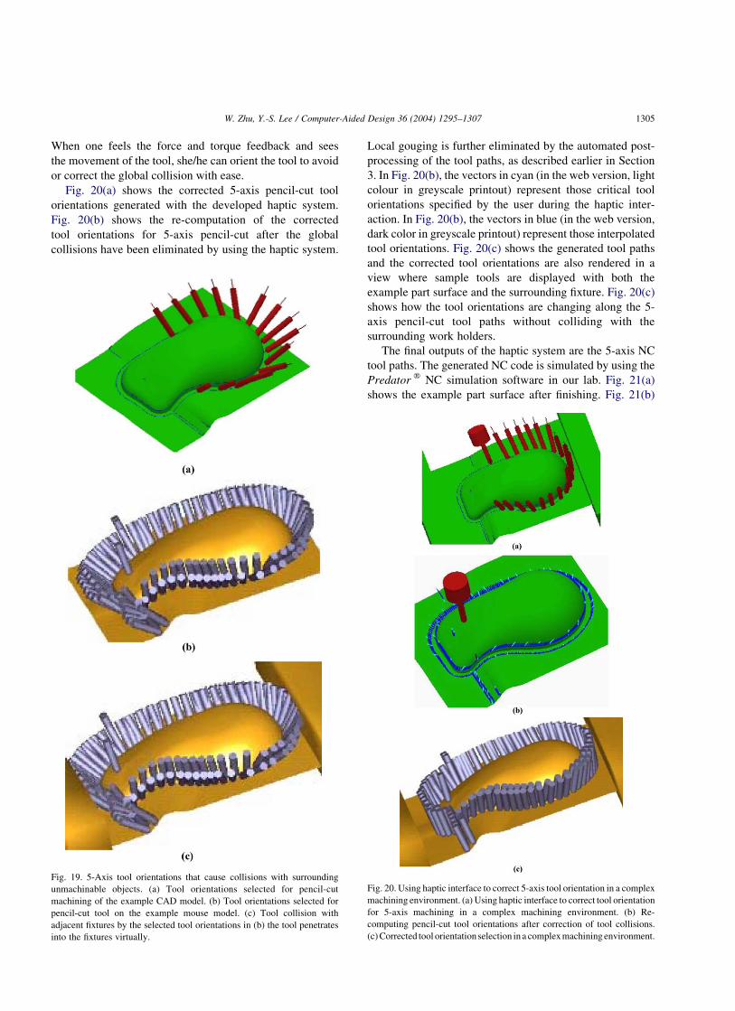
developed in our earlier work in Ref. [14,18]. Fig. 19(a)
shows some sample 5-axis tool orientations for machining of
the pencil-cut critical regions of the example part. Fig. 19(b)
shows the generated 5-axis pencil-cut tool paths for
machining the pencil-cut regions on the example part
surface. The tool holders are temporarily hidden in
Fig. 19(b) to show the tool orientations more clearly. Without
considering the surrounding machining environment, 5-axis
tool paths could easily collide with the adjacent object
unintentionally. It can be seen from Fig. 19(c) that
the generated 5-axis tool paths are actually colliding with
the fixtures nearby during 5-axis tool motions. As demon-
strated in Fig. 19(c), these tools actually penetrate the
fixtures. By taking the whole machining environments into
account, the haptic system actually responds and enables the
user to feel the collision force feedback. By using the haptic
interface, the user is able to correct the tool orientations.
Fig. 17. Force and torque distribution to two haptic manipulators.
Fig. 18. Pencil-cut tool path (dark blue trajectories) identified on an example computer mouse model. (a) An overview of haptics operation process of the 5-axis
pencil-cut path planning. (b) An STL model of example computer mouse. (c) Pencil-cut tool path on the example STL model (For interpretation of the
references to colour in this figure legend, the reader is referred to the web version of this article).
W. Zhu, Y.-S. Lee / Computer-Aided Design 36 (2004) 1295–13071304
When one feels the force and torque feedback and sees
the movement of the tool, she/he can orient the tool to avoid
or correct the global collision with ease.
Fig. 20(a) shows the corrected 5-axis pencil-cut tool
orientations generated with the developed haptic system.
Fig. 20(b) shows the re-computation of the corrected
tool orientations for 5-axis pencil-cut after the global
collisions have been eliminated by using the haptic system.
Local gouging is further eliminated by the automated post-
processing of the tool paths, as described earlier in Section
3. In Fig. 20(b), the vectors in cyan (in the web version, light
colour in greyscale printout) represent those critical tool
orientations specified by the user during the haptic inter-
action. In Fig. 20(b), the vectors in blue (in the web version,
dark color in greyscale printout) represent those interpolated
tool orientations. Fig. 20(c) shows the generated tool paths
and the corrected tool orientations are also rendered in a
view where sample tools are displayed with both the
example part surface and the surrounding fixture. Fig. 20(c)
shows how the tool orientations are changing along the 5-
axis pencil-cut tool paths without colliding with the
surrounding work holders.
The final outputs of the haptic system are the 5-axis NC
tool paths. The generated NC code is simulated by using the
Predator w NC simulation software in our lab. Fig. 21(a)
shows the example part surface after finishing. Fig. 21(b)
Fig. 19. 5-Axis tool orientations that cause collisions with surrounding
unmachinable objects. (a) Tool orientations selected for pencil-cut
machining of the example CAD model. (b) Tool orientations selected for
pencil-cut tool on the example mouse model. (c) Tool collision with
adjacent fixtures by the selected tool orientations in (b) the tool penetrates
into the fixtures virtually.
Fig. 20. Using haptic interface to correct 5-axis tool orientation in a complex
machining environment. (a) Using haptic interface to correct tool orientation
for 5-axis machining in a complex machining environment. (b) Re-
computing pencil-cut tool orientations after correction of tool collisions.
(c) Corrected tool orientation selection in a complex machining environment.
W. Zhu, Y.-S. Lee / Computer-Aided Design 36 (2004) 1295–1307 1305
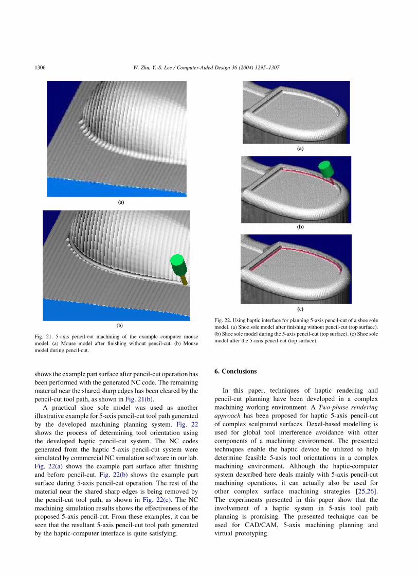
shows the example part surface after pencil-cut operation has
been performed with the generated NC code. The remaining
material near the shared sharp edges has been cleared by the
pencil-cut tool path, as shown in Fig. 21(b).
A practical shoe sole model was used as another
illustrative example for 5-axis pencil-cut tool path generated
by the developed machining planning system. Fig. 22
shows the process of determining tool orientation using
the developed haptic pencil-cut system. The NC codes
generated from the haptic 5-axis pencil-cut system were
simulated by commercial NC simulation software in our lab.
Fig. 22(a) shows the example part surface after finishing
and before pencil-cut. Fig. 22(b) shows the example part
surface during 5-axis pencil-cut operation. The rest of the
material near the shared sharp edges is being removed by
the pencil-cut tool path, as shown in Fig. 22(c). The NC
machining simulation results shows the effectiveness of the
proposed 5-axis pencil-cut. From these examples, it can be
seen that the resultant 5-axis pencil-cut tool path generated
by the haptic-computer interface is quite satisfying.
6. Conclusions
In this paper, techniques of haptic rendering and
pencil-cut planning have been developed in a complex
machining working environment. A Two-phase rendering
approach has been proposed for haptic 5-axis pencil-cut
of complex sculptured surfaces. Dexel-based modelling is
used for global tool interference avoidance with other
components of a machining environment. The presented
techniques enable the haptic device be utilized to help
determine feasible 5-axis tool orientations in a complex
machining environment. Although the haptic-computer
system described here deals mainly with 5-axis pencil-cut
machining operations, it can actually also be used for
other complex surface machining strategies [25,26].
The experiments presented in this paper show that the
involvement of a haptic system in 5-axis tool path
planning is promising. The presented technique can be
used for CAD/CAM, 5-axis machining planning and
virtual prototyping.
Fig. 21. 5-axis pencil-cut machining of the example computer mouse
model. (a) Mouse model after finishing without pencil-cut. (b) Mouse
model during pencil-cut.
Fig. 22. Using haptic interface for planning 5-axis pencil-cut of a shoe sole
model. (a) Shoe sole model after finishing without pencil-cut (rop surface).
(b) Shoe sole model during the 5-axis pencil-cut (top surface). (c) Shoe sole
model after the 5-axis pencil-cut (top surface).
W. Zhu, Y.-S. Lee / Computer-Aided Design 36 (2004) 1295–13071306
Acknowledgements
This work was partially supported by the National Science
Foundation (NSF) CAREER Award (DMI-9702374), NSF
Grant (DMI-0300297) and the Army Research Office (Grant
#DAAG55-98-D-0003) to Dr Y. S. Lee at North Carolina
State University. Their support is greatly appreciated. The
authors would also like to thank Dr Y. Adachi at Suzuki, Inc.
(Japan), Dr S. Sarma at MIT, and Dr Y. Ren at NCSU for their
helpful discussion and suggestions.
References
[1] Choi BK, Jerard RB. Sculptured surface machining. Boston: Kluwer
Academic Publishers; 1998.
[2] Jun C-S, Cha K, Lee Y-S. Optimizing tool orientation for 5-axis
machining by configuration-space search method. Comput-Aided Des
2003;35:549–66.
[3] Lee Y-S. Mathematical modeling using different endmills and tool
placement problems for 4- and 5-axis NC complex surface machining.
Int J Prod Res 1998;36(3):785–814.
[4] Biggs J, Srinivasan MA. Haptic interfaces. In: Stanney K, editor.
Handbook of virtual environments. London: Lawrence Earlbaum, Inc;
2002.
[5] Srinivasan MA, Basdogan C. Haptics in virtual environments:
taxonomy, research status, and challenges. Comput Graph 1997;
21(4):393–404.
[6] Thompson IITV, Johnson DE, Cohen E. Direct haptic rendering of
sculptured models. Proceedings Symposium on Interactive 3D
Graphics, Providence, RI, April 27–30; 1997. p. 1–10.
[7] Dachille IX F, Qin H, Kaufman A. A Novel haptic-based Interface and
sculpting system for physics-based geometric design. Comput-Aided
Des 2001;33:403–20.
[8] Leu MC, Velivelli A, Peng X. Creating freeform model by carving
virtual workpiece with haptic interface. Proceedings of
ASME International Mechanical Engineering Congress and
Exposition (IMECE), Nov. 17–22, New Orleans, LA; 2002. p. 32467.
[9] Wang WS, Kaufman AE. Volume Sculpting, ACM Symposium on
Interactive 3D Graphics, Monterey CA, USA. ; 1995. p. 151–6, 214.
[10] Ho S, Sarma S, Adachi Y. Realtime interference analysis between a
tool and an environment. Comput-Aided Des 2001;33:935–47.
[11] Balasubramaniam M, Ho S, Sarma S, Adachi Y. Generation of
collision-free 5-axis tool paths using a haptic surface. Comput-Aided
Des 2002;34:267–79.
[12] Zhu W, Lee Y-S. Haptic sculpting and pencil-cut planning in virtual
prototyping and manufacturing. Proceedings of The ASME Inter-
national Mechanical Engineering Congress and Exposition (IMECE)
Conference, Washington DC, November 16–21, Paper number
IMECE2003; 2003. 42489.
[13] Zhu W, Lee Y-S. Haptic sculpting and machining planning with 5-
DOF haptic interface for virtual prototyping and manufacturing.
Proceedings of The International Conference on Advanced Research
in Virtual and Rapid Prototyping (VRAP 2003), Leiria, Portugal,
October 1–4; 2003. p. 225–32.
[14] Ren Y, Lee Y-S, Yau HT. Contraction tool method and clean-up tool
path generation for machining polynomial models. Comput Ind 2004;
in press.
[15] Chiou CJ, Lee Y-S. Machining potential field approach to tool path
generation for multi-axis sculptured surface machining. Comput-
Aided Des 2002;34:357–71.
[16] Lee Y-S. Two-phase approach to global tool interference avoidance in
5-axis machining. Comput-Aided Des 1995;27:715–29.
[17] Koc K, Ma Y, Lee Y-S. Smoothing STL files by Max-Fit Biarcs curves
for rapid prototyping. Rapid Prototyping J 2000;6(3):186–204.
[18] Lee Y-S, Ma Y, Jegadesh G. Rolling-ball method and contour
marching approach to identifying critical regions for complex surface
machining. Comput Ind 2000;41(2):163–80.
[19] Craig JJ. Introduction to robotics: mechanics and control. New York:
Addison-Wesley; 1989.
[20] Klosowski JT, Held M, Mitchell JSB, Sowizral H, Zikan K. Efficient
collision detection using bounding volume hierarchies of k-DOPs.
IEEE Trans Vis Comput Graph 1998;4(1):21–36.
[21] McNeely WA, Puterbaugh KD, Troy JJ. Six degree-of-freedom
rendering using voxel sampling. Comput Graph (Proc SIGGRAPH’99);
1999. p. 401–8.
[22] Gottschalk S, Lin MC, Manocha D. OBBTree: A Hierarchical
Structure for Rapid Interference Detection. Comput Graph (SIG-
GRAPH’96 Proc) 1996;August:171–80.
[23] Chiou CJ, Lee Y-S. A shape-generating approach for multi-
axis machiningG-buffer models. Comput-AidedDes 1999;31:761–76.
[24] Van Hook T. Real-time shaded NC milling display. Comput Graph
(Proc. SIGGRAPH‘86) 1986;20(4):15–20.
[25] Zhu W, Lee Y-S. Analytical methodology of updating Dexel volume
models for virtual sculpting with 5-DOF haptic interface (in review);
2003. Submitted for publication.
[26] Zhu W, Lee Y-S. A marching algorithm of constructing polyhedral
models from Dexel models for haptic virtual sculpting (in review)
2003. Submitted for publication.
Weihang Zhu is a PhD student in the Depart-
ment of Industrial Engineering, North Carolina
State University, USA. He received his BS and
MS, both in Energy Engineering, from Zhejiang
University, China, in 1997 and 2000, respect-
ively. His research interests include Computer
haptics, CAD/CAM, multi-axis NC surface
machining, polyhedral machining, applied
computational geometry, discrete-event com-
puter simulation, and logistics.
Yuan-Shin Lee is Professor of Industrial
Engineering at North Carolina State University,
USA. He received his PhD (1993) and MS
(1990) degrees from Purdue University, USA,
both in industrial engineering, and his BS
degree from National Taiwan University,
Taiwan, in mechanical engineering. His
research interests include 3- and 5-axis sculp-
tured surface manufacturing, CAD/CAM, com-
putational geometry for design and
manufacturing, rapid prototyping, and high
speed machining. He is a registered Pro-
fessional Engineer (PE) in mechanical engineering. He is also a certified
manufacturing engineer in system integration and control. Dr Lee received
the National Science Foundation (NSF) CAREER Award. He also received
the 1997 Outstanding Young Manufacturing Engineer Award from the
Society of Manufacturing Engineers (SME), the 1998 Norman Dudley Award
from the Taylor and Francis Journals, London, U.K., the 1999 Anderson
Outstanding Faculty Award and the 2000 Alumni Faculty Outstanding
Teaching Award from North Carolina State University, and the 2001 ALCOA
Foundation Engineering Research Achievement Award. He serves as an
Associate Editor for the Journal of Manufacturing Systems (JMS).
W. Zhu, Y.-S. Lee / Computer-Aided Design 36 (2004) 1295–1307 1307