www.Fisher.com
Fisher™ 585C Series Piston Actuators
ContentsIntroduction 1. . . . . . . . . . . . . . . . . . . . . . . . . . . . . . . . .
Scope of Manual 1. . . . . . . . . . . . . . . . . . . . . . . . . . . . .Description 2. . . . . . . . . . . . . . . . . . . . . . . . . . . . . . . . .Specifications 2. . . . . . . . . . . . . . . . . . . . . . . . . . . . . . .Educational Services 2. . . . . . . . . . . . . . . . . . . . . . . . .
Principle of Operation 8. . . . . . . . . . . . . . . . . . . . . . . . .Actuator with Handwheel 8. . . . . . . . . . . . . . . . . . . . .Actuator with Spring Return 10. . . . . . . . . . . . . . . . . .
Installation 10. . . . . . . . . . . . . . . . . . . . . . . . . . . . . . . . .Bypass Assembly 11. . . . . . . . . . . . . . . . . . . . . . . . . . .Three‐Way Valve Applications Note 11. . . . . . . . . . . .
Actuator Mounting 11. . . . . . . . . . . . . . . . . . . . . . . . . . .Size 25 & 50 Actuator Mounting 11. . . . . . . . . . . . . . .Size 60‐130 Actuator Mounting 13. . . . . . . . . . . . . . .
Stem Connector Assembly (Size 60‐130) 13. . . .585C Handwheels 14. . . . . . . . . . . . . . . . . . . . . . . . . . .
Handwheel Operation (Sizes 25 & 50) 14. . . . . . . . . .Handwheel Operation (Sizes 60‐130) 14. . . . . . . . . .
Maintenance (Sizes 25 & 50) 15. . . . . . . . . . . . . . . . . . .Replacing Handwheel Housing O‐Ring or
Thrust Bearings (Sizes 25 & 50) 16. . . . . . . . . . . . .Replacing Seals, Changing Action, or
Changing Bias Spring(s) (Sizes 25 & 50) 17. . . . . .Maintenance (Sizes 60‐130) 20. . . . . . . . . . . . . . . . . . .
Side‐Mounted Handwheel Maintenance(Sizes 60‐130) 21. . . . . . . . . . . . . . . . . . . . . . . . . . .
Disassembly of Handwheel Constructions(Sizes 60 and 68) 21. . . . . . . . . . . . . . . . . . . . .
Figure 1. Fisher 585C Series Piston Actuator
X0175-1
Disassembly of Handwheel Constructions(Sizes 80‐130) 22. . . . . . . . . . . . . . . . . . . . . . . .
Reassembly (Sizes 60‐130) 22. . . . . . . . . . . . . . .Parts Ordering 22. . . . . . . . . . . . . . . . . . . . . . . . . . . . . . .Parts Kits 23. . . . . . . . . . . . . . . . . . . . . . . . . . . . . . . . . . .Parts List 24. . . . . . . . . . . . . . . . . . . . . . . . . . . . . . . . . . .
Sizes 25 & 50 24. . . . . . . . . . . . . . . . . . . . . . . . . . . . . . .Sizes 60‐130 30. . . . . . . . . . . . . . . . . . . . . . . . . . . . . . .
Introduction
Scope of ManualThis instruction manual provides information on installation, maintenance, and parts ordering for the Fisher 585Cpiston actuators. Refer to separate instruction manuals for information about other equipment and accessories usedwith these actuators.
Information for the 585CLS long stroke actuator can be found in the Fisher 585CLS instruction manual(D103793X012).
Do not install, operate, or maintain a 585C Series actuator without being fully trained and qualified in valve, actuator,and accessory installation, operation, and maintenance. To avoid personal injury or property damage, it is importantto carefully read, understand, and follow all the contents of this manual, including all safety cautions and warnings. Ifyou have any questions about these instructions, contact your Emerson sales office or Local Business Partner beforeproceeding.
Instruction ManualD102087X012
585C ActuatorJune 2017

Instruction ManualD102087X012
585C ActuatorJune 2017
2
Description585C pneumatic piston actuators ( figure 1) provide accurate throttling or on‐off control of sliding‐stem valves. The585C actuator uses a double‐acting cylinder, which requires air pressure for operation.
Size 25 and 50 actuators are available as a springless construction or with a bias spring. Depending on configuration,the bias spring will retract or extend the piston rod upon loss of cylinder air pressure. Size 60 through 130 actuators areavailable as springless constructions only.
585C actuators are typically supplied with a DVC6200 digital valve controller, or a 3600 P/P or I/P analog positioner.The 585C actuator is available with a top‐mounted or side‐mounted manual handwheel, depending on actuator size.
SpecificationsSpecifications for the 585C piston actuators are given in table 1. Some individual actuators come from the factory withspecifications stamped on a nameplate attached to the yoke.
Educational ServicesFor information on available courses for Fisher 585C Series piston actuators, as well as a variety of other products,contact:
Emerson Automation SolutionsEducational Services - RegistrationPhone: 1-641-754-3771 or 1-800-338-8158E-mail: [email protected]/fishervalvetraining

Instruction ManualD102087X012
585C ActuatorJune 2017
3
Table 1. 585C Specifications (sizes 25‐130)
Operating Pressure(1)
Sizes 25‐50Maximum Allowable: 10.3 bar (150 psig)Minimum Recommended: 1.4 bar (20 psig)Sizes 60‐130Maximum Allowable: See table 8Minimum Recommended: 2.4 bar (35 psig)
Travel
See table 2
Thrust Capabilities
See tables 4 through 8
Stroking Speeds
Varies with actuator size, actuator spring, travel, andsupply pressure. If stroking speed is critical, consultyour Emerson sales office or Local Business Partner
Piston Area
See table 2
Cylinder Volumetric Displacement
See table 2
Operative Temperature Limits(1)
For All SizesWith Nitrile O‐Rings: -40 to 80�C (-40 to 175�F),standardWith Fluorocarbon O‐Rings: -18 to 149�C(0 to 300�F), optional
Yoke Boss and Valve Stem Diameters
See table 3
Pressure Connections
Size 25‐60� 1/4 NPT internal (standard), or � 3/8 NPT internal(optional)Sizes 68‐130� 1/2 NPT internal (standard)
Instrument Mounting
Universal NAMUR mounting
Construction Materials
Part Material
Yoke Ductile Iron
Piston Aluminum
Cylinder Aluminum
Bolting and Fasteners NCF (non‐corroding finish)
Springs(sizes 25 & 50 only)
Alloy Steel
O‐Rings Nitrile (std), Fluorocarbon
Actuator Stem Chrome‐plated Steel
Stem Connection Stainless Steel
Travel Indicator Scale Stainless Steel
Paint Polyester Powder
Cylinder Seal Bushings(sizes 60‐130 only)
Brass
Stem Connector(sizes 60‐130)
Zinc‐plated steel
Approximate Weights (less positioner andhandwheel)
Size 252‐1/8 inch yoke boss, 7 kg (16 pounds)2‐13/16 inch yoke boss, 8 kg (17 pounds)Size 502‐13/16 inch yoke boss, 20 kg (45 pounds)3‐9/16 inch yoke boss, 22 kg (48 pounds)Size 60: 31 kg (68 pounds)Size 68: 54 kg (120 pounds)Size 80: 102 kg (225 pounds)Size 100: 113 kg (250 pounds)Size 130: 188 kg (415 pounds)
Options
Sizes 25 and 50� Top‐mounted handwheel, see figures 5, 7, and 8and table 9� Cylinder bypass valve � Limit switches � Fisher4200 position transmitterSizes 60‐130� Integral side‐mounted handwheel, (figure 9)Sizes 25‐130� FIELDVUE� mounting options� Fisher 377 trip valve system to fail actuator� up or � down or � lock in last position� TopWorx� DXP M21GNEB electrical valve stemposition switch� Micro‐Switch limit switches
1. The pressure/temperature limits in this manual and any applicable standard or code limitation for valve should not be exceeded.
Instruction ManualD102087X012
585C ActuatorJune 2017
4
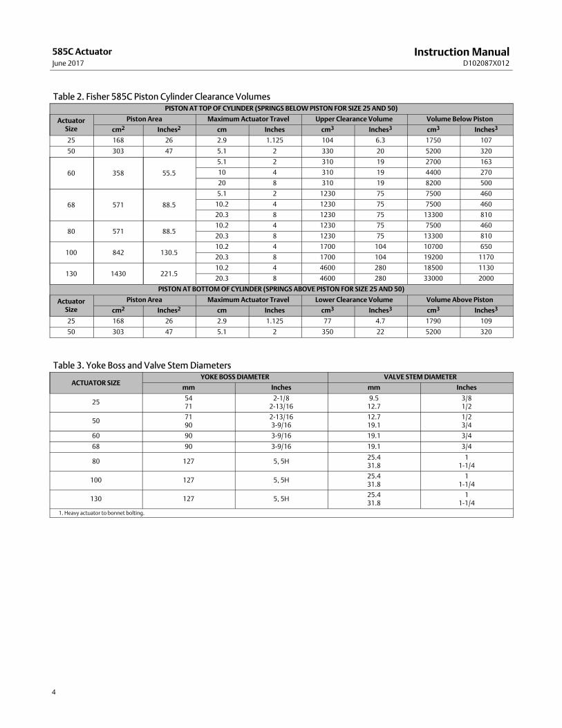
Table 2. Fisher 585C Piston Cylinder Clearance VolumesPISTON AT TOP OF CYLINDER (SPRINGS BELOW PISTON FOR SIZE 25 AND 50)
ActuatorSize
Piston Area Maximum Actuator Travel Upper Clearance Volume Volume Below Piston
cm2 Inches2 cm Inches cm3 Inches3 cm3 Inches3
25 168 26 2.9 1.125 104 6.3 1750 107
50 303 47 5.1 2 330 20 5200 320
60 358 55.5
5.1 2 310 19 2700 163
10 4 310 19 4400 270
20 8 310 19 8200 500
68 571 88.5
5.1 2 1230 75 7500 460
10.2 4 1230 75 7500 460
20.3 8 1230 75 13300 810
80 571 88.510.2 4 1230 75 7500 460
20.3 8 1230 75 13300 810
100 842 130.510.2 4 1700 104 10700 650
20.3 8 1700 104 19200 1170
130 1430 221.510.2 4 4600 280 18500 1130
20.3 8 4600 280 33000 2000
PISTON AT BOTTOM OF CYLINDER (SPRINGS ABOVE PISTON FOR SIZE 25 AND 50)
ActuatorSize
Piston Area Maximum Actuator Travel Lower Clearance Volume Volume Above Piston
cm2 Inches2 cm Inches cm3 Inches3 cm3 Inches3
25 168 26 2.9 1.125 77 4.7 1790 109
50 303 47 5.1 2 350 22 5200 320
Table 3. Yoke Boss and Valve Stem Diameters
ACTUATOR SIZEYOKE BOSS DIAMETER VALVE STEM DIAMETER
mm Inches mm Inches
255471
2‐1/82‐13/16
9.512.7
3/81/2
507190
2‐13/163‐9/16
12.719.1
1/23/4
60 90 3‐9/16 19.1 3/4
68 90 3‐9/16 19.1 3/4
80 127 5, 5H25.431.8
11‐1/4
100 127 5, 5H25.431.8
11‐1/4
130 127 5, 5H25.431.8
11‐1/4
1. Heavy actuator to bonnet bolting.

Instruction ManualD102087X012
585C ActuatorJune 2017
5
Actuator Thrust Capabilities
Table 4. Fisher 585C Size 25 and 50 Actuator Thrust Capabilities, U.S. Units (spring retracts actuator stem)
ACTU‐ATORSIZE
SPRINGRATE,lb/in
ACTUATORSTEM
TRAVEL,INCHES
SPRINGTHRUST W/ACTUATOR
STEMRETRACTED,
POUNDS
SPRINGTHRUST W/ACTUATOR
STEMEXTENDED,
POUNDS
NET THRUST FOR 585C WITH ACTUATOR STEM FULLYEXTENDED AT FULL TRAVEL SPRINGS
USED,BY
COLOR
Operating Pressure, psig
40 50 60 70 80 90 100 110 125 150
Force, Pounds
25
0 All 0 0 1040 1300 1560 1820 2080 2340 2600 2860 3250 3900Springs
Not Used
200
0.56250.75
0.8751.125
200200200200
313350375425
730690660610
990950920870
1250121011801130
1510147014401390
1760173017001650
2020199019601910
2280225022202170
2540251024802430
2930290028702820
3580355035203470
Gold
400
0.56250.75
0.8751.125
400400400400
625700750850
410340290190
670600550450
930860810710
119011201070970
1450138013301230
1710164015901490
1970190018501750
2230216021102010
2620255025002400
3270320031503050
LightGreen
500
0.56250.75
0.8751.125
500500500500
781875938
1063
260160100
X
520420360240
780680620500
1040940880760
1300120011401010
1560146014001270
1820172016601530
2080198019201790
2460237023102180
3110302029602830
White
700
0.56250.75
0.8751.125
700700700700
1094122513131488
XXXX
20070XX
46033025070
720590510330
980850760590
124011101020850
1500137012801110
1760163015401370
2150202019301760
2800267025802410
Gold &White
900
0.56250.75
0.8751.125
900900900900
1406157516881913
XXXX
XXXX
150XXX
410240130
X
670500390160
930760650420
11901020910680
145012801170940
1840167015601330
2490232022101980
LightGreen
& White
50
0 All 0 0 1840 2300 2760 3220 3680 4140 4600 5060 5750 6900Springs
Not Used
330
0.750.8751.125
1.52
330330330330330
578619701825990
1310127011801060900
17801740166015301370
22502210213020001840
27202680260024702310
31903150307029502780
36603620354034203250
41404090401038903720
46104570448043604190
53105270519050704900
64906450637062506080
Pink
600
0.750.8751.125
1.52
600600600600600
10501125127515001800
84076061039090
131012301080860560
17801700155013301030
22502170202018001500
27202650250022701970
31903120297027402440
36603590344032102910
41304060391036803380
48404770462043904090
60205950580055705270
LightBlue
930
0.750.8751.125
1.52
930930930930930
16281744197623252790
260140
XXX
73061038030X
1200108085050040
167015601320970510
2140203017901450980
26102500227019201450
30902970274023901920
35603440321028602390
42604150391035703100
54405330509047504280
Pink &LightBlue
1550
0.750.8751.125
1.52
15501550155015501550
27102906329438754650
XXXXX
XXXXX
110XXXX
580385
XXX
1050855465
XX
15201325935355
X
19901795140582550
2460226518751295520
31652970258020001225
43454150376031802405
Green
1880
0.750.8751.125
1.52
18801880188018801880
32903525399547005640
XXXXX
XXXXX
XXXXX
XXXXX
470235
XXX
940705235
XX
14101175705
XX
188016451175470
X
2585235018801175235
37653530306023551415
Pink &Green
X—Indicates where the listed supply pressure is not sufficient to overcome the opposing bias spring effect.

Instruction ManualD102087X012
585C ActuatorJune 2017
6
Table 5. Fisher 585C Size 25 and 50 Actuator Thrust Capabilities, Metric Units (spring retracts actuator stem)
ACTU‐ATORSIZE
SPRINGRATE,N/mm
ACTU‐ATORSTEM
TRAVEL,mm
SPRINGTHRUST W/ACTUATOR
STEMRETRACTED,
N
SPRINGTHRUST W/ACTUATOR
STEMEXTENDED,
N
NET THRUST FOR 585C WITH ACTUATOR STEM FULLYEXTENDED AT FULL TRAVEL SPRINGS
USED,
BY
COLOR
Operating Pressure, bar
2.8 3.4 4.1 4.8 5.5 6.2 6.9 7.6 8.6 10.3
Force, N
25
0 All 0 0 4626 5783 6939 8096 9252 10,409 11,565 12,722 14,457 17,348Springs
NotUsed
35.0
14.319.122.228.6
890890890890
1393155816691891
3247306929362713
4404422640923870
5560538252495026
6717653964056183
7829769575627340
8985885287188496
10,14210,008
98759653
11,29811,16511,03210,809
13,03312,90012,76612,544
15,92515,79115,65815,435
Gold
70.1
14.319.122.228.6
1780178017801780
2781311533383783
182415121290845
2980266924472002
4137382536033158
5293498247604315
6450613959165471
7606729570736628
8763845282297784
9919960893868941
11,65411,34311,12110,676
14,54614,23414,01213,567
LightGreen
87.6
14.319.122.228.6
2225222522252225
3475389441744730
1156712445
X
2313186816011068
3470302527582224
4626418139143381
5783533850714493
6939649462275649
8096765173846806
9252880785417962
10,94310,54210,275
9697
13,83413,43413,16712,588
White
122.6
14.319.122.228.6
3115311531153115
4868545158436622
XXXX
890311
XX
204614681112311
3203262422691468
4359378133812624
5516493845373781
6672609456944938
7829725168506094
9564898585857829
12,45511,87711,47610,720
Gold &White
157.7
14.319.122.228.6
4005400540054005
6257700975128513
XXXX
XXXX
667XXX
18241068578
X
298022241735712
4137338128911868
5293453740483025
6450569452044181
8185742869395916
11,07610,320
98318807
LightGreen &
White
50
0 All 0 0 8180 10,200 12,300 14,300 16,400 18,400 20,500 22,500 25,600 30,700Springs
NotUsed
57.8
19.122.228.638.150.8
14681468146814681468
25712753311836704404
58275649524947154003
79187740738468066094
10,0089831947588968185
12,09911,92111,56510,98710,275
14,19014,01213,65613,12212,366
16,28016,10215,74715,21314,457
18,41618,19317,83717,30316,547
20,50620,32819,92819,39418,638
23,62023,44223,08622,55221,796
28,86928,69128,33527,80127,045
Pink
105.1
19.122.228.638.150.8
26692669266926692669
46715004567166728007
3736338127131735400
58275471480438252491
79187562689559164582
10,0089653898580076672
12,09911,78811,12110,097
8763
14,19013,87813,21112,18810,854
16,28015,96915,30214,27912,944
18,37118,06017,39216,36915,035
21,52921,21820,55119,52818,193
26,77826,46725,80024,77723,442
LightBlue
162.9
19.122.228.638.150.8
41374137413741374137
724277588790
10,34212,410
1157623
XXX
324727131690133
X
5338480437812224178
74286939587243152269
95199030796264504359
11,61011,12110,097
85416450
13,74513,21112,18810,631
8541
15,83615,30214,27912,72210,631
18,94918,46017,39215,88013,789
24,19823,70922,64121,12919,038
Pink &LightBlue
271.4
19.122.228.638.150.8
68946894689468946894
1205412925146521723620683
XXXXX
XXXXX
489XXXX
25801712
XXX
467038032068
XX
6761589441591579
X
8852798462493670222
1094210075834057602313
14078132111147688965449
19,32818,46016,72514,14510,698
Green
329.2
19.122.228.638.150.8
83628362836283628362
1463415679177702090625087
XXXXX
XXXXX
XXXXX
XXXXX
20911045
XXX
418131361045
XX
627252263136
XX
8362731752262091
X
1149810453836252261045
16,74815,70213,61210,476
6294
Pink &Green
X—Indicates where the listed supply pressure is not sufficient to overcome the opposing bias spring effect.

Instruction ManualD102087X012
585C ActuatorJune 2017
7
Table 6. Fisher 585CR Size 25 and 50 Actuator Thrust Capabilities, U.S. Units (spring extends actuator stem)
ACTUATORSIZE
SPRINGRATE,lb/in
SPRINGTHRUST W/ACTUATOR
STEMEXTENDED,
POUNDS
TOTAL THRUST FOR 585CR WITH ACTUATOR STEM FULLYEXTENDED
SPRINGS USED, BY COLOROperating Pressure, psig(1)
40 50 60 70 80 90 100 110 125 150
Force, Pounds
25(2)
0 0 1040 1300 1560 1820 2080 2340 2600 2860 3250 3900 Springs Not Used
200 200 1240 1500 1760 2020 2280 2540 2800 3060 3450 X Gold
400 400 1440 1700 1960 2220 2480 2740 3000 3260 3650 X Light Green
500 500 1540 1800 2060 2320 2580 2840 3100 3360 3750 X White
700 700 1740 2000 2260 2520 2780 3040 3300 3560 X X Gold & White
900 900 1940 2200 2460 2720 2980 3240 3500 3760 X X Light Green & White
50(3)
0 0 1840 2300 2760 3220 3680 4140 4600 5060 5750 6900 Springs Not Used
330 330 2210 2680 3150 3620 4090 4560 5030 5500 6205 X Pink
600 600 2480 2950 3420 3890 4360 4830 5300 5770 6475 X Light Blue
930 930 2810 3280 3750 4220 4690 5160 5630 6100 6805 X Pink & Light Blue
1550 1550 3430 3900 4370 4840 5310 5780 6250 6720 X X Green
1880 1880 3760 4230 4700 5170 5640 6110 6580 7050 X X Pink & Green
X—Indicates where the listed supply pressure is not sufficient to overcome the opposing bias spring effect.1. The maximum design pressure for size 25 and 50 actuator is 150 psig.2. Maximum thrust is 3900 lbs.3. Maximum thrust is 6900 lbs.
Table 7. Fisher 585CR Size 25 and 50 Actuator Thrust Capabilities, Metric Units (spring extends actuator stem)
ACTUATORSIZE
SPRINGRATE,N/mm
SPRINGTHRUST W/ACTUATOR
STEMEXTENDED,
N
TOTAL THRUST FOR 585CR WITH ACTUATOR STEM FULLYEXTENDED
SPRINGS USED, BYCOLOR
Operating Pressure, bar(1)
2.8 3.4 4.1 4.8 5.5 6.2 6.9 7.6 8.6 10.3
Force, N
25(2)
0 0 4626 5782 6939 8095 9251 10408 11565 12721 14456 17347 Springs Not Used
35.0 890 5516 6672 7828 8985 10141 11298 12454 13610 15346 X Gold
70.0 1780 6405 7562 8718 9874 11031 12188 13344 14500 16235 X Light Green
87.6 2225 6850 8006 9163 10319 11476 12632 13789 14945 16680 X White
122.6 3115 7740 8896 10052 11209 12365 13655 14678 15835 X X Gold & White
157.6 4005 8629 9786 10942 12099 13255 14412 15568 16724 X X Light Green & White
50(3)
0 0 8180 10200 12300 14300 16400 18400 20500 22500 25600 30700 Springs Not Used
57.8 1468 9830 11921 14011 16102 18192 20282 22373 24464 27600 X Pink
105.1 2670 11031 13122 15212 17303 19393 21484 23574 25665 28800 X Light Blue
162.8 4135 12499 14589 16680 18770 20861 22952 25042 27133 30269 X Pink & Light Blue
271.4 6894 15256 17347 19438 21528 23619 25709 27800 29891 X X Green
329.2 8362 16724 18815 20906 22996 25087 27177 29268 31358 X X Pink & Green
X—Indicates where the listed supply pressure is not sufficient to overcome the opposing bias spring effect.1. The maximum design pressure for size 25 and 50 actuator is 10.3 bar.2. Maximum thrust is 17347 N.3. Maximum thrust is 31358 N.

Instruction ManualD102087X012
585C ActuatorJune 2017
8
Table 8. Fisher 585C Thrust (springless construction)
ACTUATORSIZE
PISTONAREA
TOTAL THRUST FOR 585C(1)
MAXIMUM ALLOWABLETHRUST
Operating Pressure, bar(3)
2.8 3.4 4.1 4.8 5.5 6.2 6.9 7.6 8.6 10.3
cm2 Force, Newtons(2) Newtons
25 168 4630 5780 6940 8100 9260 10400 11600 12700 14500 17300 17300
50 303 8180 10200 12300 14300 16400 18400 20500 22500 25600 30700 31400
60 358 9880 12300 14800 17300 19800 22200 24700 27200 30900 36900 36900
68 571 15700 19700 23600 27600 31500 35400 39400 43300 49200 55600 55600(4)
80 571 15700 19700 23600 27600 31500 35400 39400 43300 49200 58700 58700
100 842 23200 29000 34800 40600 46400 52200 58000 63900 72600 86700 86700
130 1430 39400 49300 59100 69000 78700 88500 98800 108100 X X 111200
ACTUATORSIZE
PISTONAREA
Operating Pressure, psig(3)MAXIMUM ALLOWABLE
THRUST40 50 60 70 80 90 100 110 125 150
Inches2 Force, Pounds(2) Pounds
25 26 1040 1300 1560 1820 2080 2340 2600 2860 3250 3900 3900
50 47 1840 2300 2760 3220 3680 4140 4600 5060 5750 6900 7050
60 55.5 2220 2780 3330 3890 4440 5000 5550 6110 6940 8300 8300
68 88.5 3540 4430 5310 6200 7080 7970 8850 9740 11100 12500 12500(4)
80 88.5 3540 4430 5310 6200 7080 7970 8850 9740 11100 13200 13200
100 130.5 5220 6530 7830 9140 10440 11700 13100 14400 16300 19500 19500
130 221.5 8860 11100 13300 15500 17700 19900 22200 24300 X X 25000
X—Indicates where the listed supply pressure will exceed the maximum thrust allowable.1. The maximum design pressure for size 25 through 100 actuators is 10.3 bar (150 psig). The size 68 and 130 actuators are limited to 9.7 and 7.8 bar (140 and 113 psig) respectively.2. The size 25 and 50 data is for the construction without a bias spring.3. Minimum operating pressure for sizes 60‐130 actuators is 2.4 bar (35 psig).4. The size 68 actuator with a handwheel is limited to 40000 Newtons (9000 lb) thrust.
Principle of OperationThe 585C piston actuator (figures 2 and 3) uses a piston that moves inside the actuator cylinder. An O‐ring (see figure3) provides a seal between the piston and the cylinder.
From an equilibrium state, the actuator reacts to a force unbalance that is created by increasing supply pressure onone side of the piston, and decreasing it on the other. This moves the piston up or down, and results in a repositioningof the valve plug.
Actuator with Handwheel (figures 2 and 5)The handwheel version can be used to open or close the valve manually (either during normal operation or in anemergency), to position the valve at any point in the stroke, or to act as a travel stop.
Size 25 and 50 actuators use an integral top‐mounted handwheel. See figure 5.
Size 60 to 130 actuators use a side‐mounted handwheel, and come with a spring‐loaded ball detent which preventsvibration from changing the handwheel setting. Handwheels for most types are either 203 mm (8 inches) in diameterwith beveled gears or 432 mm (17 inches) in diameter with worm gears.

Instruction ManualD102087X012
585C ActuatorJune 2017
9
Handwheel SpecificationsTable 9. Fisher 585C Handwheel Specifications
ACTUATOR SIZEHANDWHEEL
MOUNTING
HANDWHEELDIAMETER TURNS PER mm
TRAVEL
MAXIMUM RIMFORCE REQUIRED
HANDWHEELOUTPUT FORCE
HANDWHEELWEIGHT
mm Newtons Newtons kg
25Top‐Mounted
356 0.5 325 12,810 17
50 482 0.5 445 23,790 20
60(1)
IntegralSide‐Mounted
203 0.6 276 40000 28
60(2) 356 0.6 160 40000 30
68(1) 203 0.6 276 40000 30
68(2) 356 0.6 160 40000 33
80 432 0.4 423 50000 35
100 432 0.4 623 75600 94
130 432 0.4 623 75600 123
ACTUATOR SIZEHANDWHEEL
MOUNTING
HANDWHEELDIAMETER TURNS PER INCH
TRAVEL
MAXIMUM RIMFORCE REQUIRED
HANDWHEELOUTPUT FORCE
HANDWHEELWEIGHT
Inches Pounds Pounds Pounds
25Top‐Mounted
14 12 73 2880 37
50 19 12 100 5350 45
60(1)
IntegralSide‐Mounted
8 16 62 9000 61
60(2) 14 16 36 9000 66
68(1) 8 16 62 9000 66
68(2) 14 16 36 9000 71
80 17 10 95 11250 77
100 17 10 140 17000 208
130 17 10 140 17000 272
1. 2 and 4 inch maximum travel constructions.2. 8 inch maximum travel construction.
Figure 2. Fisher 585C Piston Actuator with Handwheel
E0410
Figure 3. Fisher 585C Piston Actuator with Spring Return
W7447‐1
PISTONO‐RING

Instruction ManualD102087X012
585C ActuatorJune 2017
10
Actuator with Spring Return (figure 3)585C size 25 & 50 actuators are available with bias springs in two configurations. The 585C actuator, with the biasspring under the piston, fully retracts the actuator stem upon loss of cylinder pressure. The 585C actuator, with thebias spring on top of the piston, fully extends the actuator stem upon loss of cylinder pressure. No additional parts arerequired to convert from one actuator type to the other.
For more detailed information on the 3610 positioner and DVC6200 digital valve controllers, refer to the Principle ofOperation section in the 3610 and DVC6200 Instruction Manuals.
Installation
WARNING
To avoid personal injury or property damage caused by cylinder fracture as a result of piston impact, install the stemconnector securely before supplying pressure to the positioner. Use only a regulator-controlled air supply to move theactuator piston so that you can install the stem connector. Do not use the positioner to move the actuator piston beforeinstalling the stem connector.
Always wear protective gloves, clothing, and eyewear when performing any installation operations to avoid personalinjury.
To avoid personal injury or property damage caused by bursting of pressure‐retaining parts, be certain the cylinderpressure or other pressure ratings do not exceed the limits listed in table 1. Use pressure‐limiting or pressure‐relievingdevices to prevent cylinder pressure or other pressure ratings from exceeding these limits.
Check with your process or safety engineer for any additional measures that must be taken to protect against processmedia.
If installing into an existing application, also refer to the WARNING at the beginning of the Maintenance sections in thisinstruction manual.
When an actuator and valve are shipped together as a control valve assembly, the actuator is normally mounted on thevalve. Follow the valve instructions when installing the control valve in the pipeline. If the actuator is shippedseparately or if it is necessary to mount the actuator on the valve, perform the Actuator Mounting procedures in thisinstruction manual corresponding to your actuator size. For information on mounting valve positioners, refer to the3610 or DVC6200 instruction manuals for details.
If a 585C actuator is being installed without a positioner, the cylinder loading pressures should be supplied through a4‐way solenoid valve or a switching valve. The bottom side of the piston is pressured through the bottom side of themounting flange on the actuator yoke (key 6, figures 4 and 6) for sizes 25 and 50 or the connection at the lower side ofthe cylinder (key 1, figure 9 to 12) for sizes 60 to 130. The top side of the piston is pressured through the connection inthe cylinder cover (key 1 for figures 4, 6; and 9 to 12).
The supply pressure medium should be clean, dry filtered air. If the supply source is capable of exceeding themaximum actuator operating pressure or positioner supply pressure, appropriate steps must be taken duringinstallation to protect the positioner and all connected equipment against overpressure.
WARNING
Dropping the actuator and any attached accessories and/or valve may cause personal injury and/or equipment damage. Forall mounting procedures use an adequately sized chain, sling, hoist, or crane to handle the actuator and any attached

Instruction ManualD102087X012
585C ActuatorJune 2017
11
accessories and/or valve. Use caution during lifting and handling to prevent slippage, swinging, faulty equipmentconnections, or sudden shock loads.
CAUTION
To avoid damage to actuator parts and difficult operation of actuator handwheels, open the bypass valve before using ahandwheel.
If manual operation is required, the actuator should be equipped with a manual handwheel. To manually move thepiston rod with the handwheel, first open the bypass needle valve (key 66 for sizes 25 and 50, figure 8; key 92 for sizes60 to 130, figure 13), place the handwheel pointer in the neutral position, and insert the locking pin in the sleeveassembly (for size 60‐130). Then turn the handwheel in the selected direction as indicated on the wheel.
The control valve should be located where it will be accessible for servicing. Room should be left above and below thecontrol valve to permit removal of the actuator and valve plug.
Bypass AssemblyThe bypass is furnished as shown in figures 5, 7, 8, and 13 only when a handwheel actuator is specified. The bypassallows the pressure to equalize on either side of the piston, so that the manual actuator can be used to position thevalve.
Flow through the bypass tubing is controlled by an angle needle valve (key 66 for figures 5, 7, and 8; and key 92 forfigure 13), which is operated manually. This valve should be closed when air pressure is being used to operate thevalve.
Three‐Way Valve Applications Note
WARNING
To avoid loss of control of process fluid and subsequent personal injury or property damage caused by bursting ofpressure‐retaining parts, be sure the cylinder pressure does not exceed 80 psig in high cycle‐rate, fast stroking speed,three‐way valve applications.
In three‐way valve applications where the actuator fully strokes at a frequency of once per minute or faster, and thestroking speed is rapid (less than 0.5 seconds per stroke), there is a possibility that the stem can fracture at the plug ifthe actuator cylinder pressure is greater than 80 psig. This can cause loss of control of process fluid and furtherdamage to the actuator. Consideration should be given to the use of high‐strength, fatigue‐resistant stem materials inthese applications.
Actuator Mounting
Size 25 and 50 Actuator MountingThe following procedure describes how to mount a 585C actuator size 25 and 50 on a push‐down‐to‐close valve sothat the piston stem to valve plug stem connection allows full travel and proper shutoff. Key numbers referenced inthe following steps are shown in figures 4 through 8.
Instruction ManualD102087X012
585C ActuatorJune 2017
12
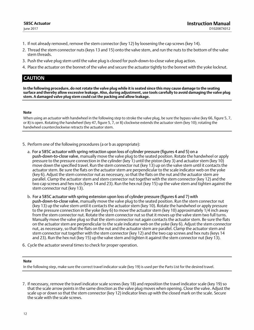
1. If not already removed, remove the stem connector (key 12) by loosening the cap screws (key 14).
2. Thread the stem connector nuts (keys 13 and 15) onto the valve stem, and run the nuts to the bottom of the valvestem threads.
3. Push the valve plug stem until the valve plug is closed for push‐down‐to‐close valve plug action.
4. Place the actuator on the bonnet of the valve and secure the actuator tightly to the bonnet with the yoke locknut.
CAUTION
In the following procedure, do not rotate the valve plug while it is seated since this may cause damage to the seatingsurface and thereby allow excessive leakage. Also, during adjustment, use tools carefully to avoid damaging the valve plugstem. A damaged valve plug stem could cut the packing and allow leakage.
Note
When using an actuator with handwheel in the following step to stroke the valve plug, be sure the bypass valve (key 66, figure 5, 7,or 8) is open. Rotating the handwheel (key 47, figure 5, 7, or 8) clockwise extends the actuator stem (key 10); rotating thehandwheel counterclockwise retracts the actuator stem.
5. Perform one of the following procedures (a or b as appropriate):
a. For a 585C actuator with spring retraction upon loss of cylinder pressure (figures 4 and 5) on apush‐down‐to‐close valve, manually move the valve plug to the seated position. Rotate the handwheel or applypressure to the pressure connection in the cylinder (key 1) until the piston (key 3) and actuator stem (key 10)move down the specified travel. Run the stem connector nut (key 13) up on the valve stem until it contacts theactuator stem. Be sure the flats on the actuator stem are perpendicular to the scale indicator web on the yoke(key 6). Adjust the stem connector nut as necessary, so that the flats on the nut and the actuator stem areparallel. Clamp the actuator stem and stem connector nut together with the stem connector (key 12) and thetwo cap screws and hex nuts (keys 14 and 23). Run the hex nut (key 15) up the valve stem and tighten against thestem connector nut (key 13).
b. For a 585C actuator with spring extension upon loss of cylinder pressure (figures 6 and 7) withpush‐down‐to‐close valve, manually move the valve plug to the seated position. Run the stem connector nut(key 13) up the valve stem until it contacts the actuator stem (key 10). Rotate the handwheel or apply pressureto the pressure connection in the yoke (key 6) to move the actuator stem (key 10) approximately 1/4 inch awayfrom the stem connector nut. Rotate the stem connector nut so that it moves up the valve stem two full turns.Manually move the valve plug so that the stem connector nut again contacts the actuator stem. Be sure the flatson the actuator stem are perpendicular to the scale indicator web on the yoke (key 6). Adjust the stem connectornut, as necessary, so that the flats on the nut and the actuator stem are parallel. Clamp the actuator stem andstem connector nut together with the stem connector (key 12) and the two cap screws and hex nuts (keys 14and 23). Run the hex nut (key 15) up the valve stem and tighten it against the stem connector nut (key 13).
6. Cycle the actuator several times to check for proper operation.
Note
In the following step, make sure the correct travel indicator scale (key 19) is used per the Parts List for the desired travel.
7. If necessary, remove the travel indicator scale screws (key 18) and reposition the travel indicator scale (key 19) sothat the scale arrow points in the same direction as the valve plug moves when opening. Close the valve. Adjust thescale up or down so that the stem connector (key 12) indicator lines up with the closed mark on the scale. Securethe scale with the scale screws.

Instruction ManualD102087X012
585C ActuatorJune 2017
13
Size 60‐130 Actuator MountingThe following procedure describes how to mount a 585C size 60 to 130 actuator on a push‐down‐to‐close valve sothat the piston stem to valve plug stem connection allows full travel and proper shutoff. Key numbers referenced inthe following steps are shown in figures 9 through 12.
If an actuator is purchased separately for field installation on a control valve, mount it on the valve and secure it inplace with the yoke locknut for size 60 and 68 or with eight bolts on actuator sizes 80, 100, and 130 which use a 127mm (5‐inch) yoke boss.
The stem connector should then be set up to clamp the actuator stem and valve plug stem together to provide theproper valve travel. This procedure is outlined in the Stem Connector Assembly procedures of this instruction manual.
Stem Connector Assembly (Size 60‐130)
CAUTION
To avoid damaging the seating surfaces, do not rotate the valve plug while it is seated. Also avoid damage to the valve plugstem by careful use of tools during travel adjustment.
WARNING
� To avoid personal injury or property damage caused by cylinder fracture as a result of piston impact, install the stemconnector securely before supplying pressure to the positioner. Incomplete engagement of valve stem and/or actuatorstem in the stem connector can result in stripped threads or improper operation. Be sure that the length of each stemclamped in the stem connector is equal to or greater than the diameter of that stem. Do not loosen the cap screwswhen the stem connector has spring or loading pressure force applied to it.
� Install the stem connector securely before a positioner is mounted to the actuator and pressurized, using only aregulator- controlled air supply, not the positioner, to move the actuator piston to position the actuator stem.
� To avoid personal injury or property damage, keep hands and tools out of the actuator stem travel path whilepressuring the actuator to move the actuator stem in the following steps.
585C Size 60‐130 Direct‐Acting (Push‐Down‐to‐Close) Valves
1. With the valve assembled and the actuator mounted, make sure the valve plug is in the closed position, and theactuator is at the top of its stroke. Then screw the two stem locknuts (key 15) all the way onto the stem thread andplace the travel indicator disk (key 32) (if any) on the stem locknuts.
2. Keeping your hands away from any moving parts, use a regulator-controlled air supply to move the actuator stem(key 10) down from the top of its stroke to the specified valve travel.
3. Using one half of the stem connector (key 12), align the actuator stem and the valve stem with threads from bothstems mated root-to-crest with the stem connector. Install the other half of the stem connector and tighten the capscrews. With the stem locknuts (key 15), raise the travel indicator disk (key 32) to the stem connector (key 12).
4. Cycle the actuator to check availability of desired total travel and that the valve plug seats before the actuatorcontacts the lower travel stop. Minor travel adjustments can be made by loosening the stem connector (key 12)slightly, tightening the locknuts (key 15) together, and screwing the valve stem either into or out of the stemconnector (key 12) with a wrench on the locknuts (key 15). If the valve stem cannot be turned, as with a bellows sealbonnet, remake the stem connection to achieve the desired travel.

Instruction ManualD102087X012
585C ActuatorJune 2017
14
5. Once the total travel is adequate, tighten the stem connector (key 12) securely, lock the stem locknuts (key 15)against the connector, and adjust the indicator scale (key 19) on the yoke to show correct valve plug position.
6. Provide a gauge to measure the pressure to the actuator. Make a final adjustment of the actuator or its positioner toset the starting point of valve travel and to obtain full travel for the given instrument range.
585C Size 60‐130 Reverse‐Acting (Push‐Down‐to‐Open) Valves
1. Keeping your hands away from moving parts, pressure the actuator, using a regulator-controlled air supply, tomove the actuator stem (key 10) to the extreme upward position then reverse loading pressure to lower theactuator stem (key 10) approximately 3 mm (1/8 inch).
2. Pull the valve stem up to seat the valve plug.
3. Using one half of the stem connector (key 12), align the actuator stem and the valve stem with threads from bothstems mated root-to-crest with the stem connector. Install the other half of the stem connector and tighten the capscrews.
4. If there is a travel indicator disk (key 32), raise it to the stem connector (key 12) and tighten in position with thestem locknuts (key 15). The indicator disk (key 32) should show the valve to be open with the piston (key 3) at thebottom of its stroke. If it does not, loosen two screws (key 18) and shift the travel indicator scale (key 19) to indicateOPEN.
5. Cycle the actuator to check availability of desired total travel and that the valve plug seats before the actuatorcontacts the upper travel stop. Minor travel adjustments can be made by loosening the stem connector (key 12)slightly, tightening the locknuts (key 15) together, and screwing the valve stem either into or out of the stemconnector (key 12) with a wrench on the locknuts. If the valve stem cannot be turned, as with a bellows seal bonnet,remake the stem connection to achieve the desired travel.
6. Once the total travel is adequate, tighten the stem connector (key 12) securely, lock the stem locknuts (key 15)against the connector, and adjust the indicator scale (key 19) on the yoke to show correct valve plug position.
7. Provide a gauge to measure the pressure to the actuator. Make a final adjustment of the actuator or its positioner toset the starting point of valve travel and to obtain full travel for the given instrument range.
585C Handwheels
Handwheel Operation (Sizes 25 & 50)Key numbers referenced in the following steps are shown in figures 5, 7, and 8 for the 585C actuator.
The handwheel assembly on a 585C actuator may be used as an adjustable travel stop to limit full upward ordownward travel of the actuator stem (key 10), or as a manual actuator to fully stroke the valve. When the neutralindicator (key 42) is in the neutral position, travel is not restricted. With clockwise handwheel (key 47) rotation, theoperating nut (key 46) is screwed downward, forcing the actuator stem (key 10) down. With counterclockwiserotation, the operating nut is screwed upward against the handwheel stem washer (key 45), pulling the actuator stemup.
Note
When using an actuator with handwheel to stroke the valve plug or position the travel stop, be sure the bypass valve (key 66) isopen.
Handwheel Operation (Sizes 60‐130)The 585C handwheel assembly for sizes 60 through 130 actuators (figures 9 and 10) has three main functions:

Instruction ManualD102087X012
585C ActuatorJune 2017
15
a. To open or close the valve manually or to position the valve at any point in the stroke, regardless of the cylinderpressure. The tapered pin is inserted during manual throttling operation.
b. To act as a travel stop to limit full opening or closing of the valve but not both at the same time. The tapered pinis left out when the assembly is used as a travel stop.
c. To open or close the valve manually in an emergency without the necessity of inserting the tapered pin.
Bevel gears are used in sizes 60 and 68 and worm gears in sizes 80 through 130. A spring‐loaded ball detent is providedin the handwheel to prevent a change in setting due to vibration. The following table 10 lists pertinent information onthese handwheel units.
Table 10. Handwheel InformationActuator Size 60‐68 80‐130
Handwheel Diameter, Inches 8 17
Turns Required for One Inch of Travel 16 10
Maintenance (Sizes 25 & 50)Actuator parts are subject to normal wear and must be inspected and replaced as necessary. The frequency ofinspection and replacement depends on the severity of service conditions. This section provides two separateprocedures, one on Replacing Handwheel Housing O‐Ring or Thrust Bearings, and the other on Replacing Seals,Changing Action, or Changing Bias Spring(s).
Refer to figures 5 and 7.
For an actuator with handwheel, a grease fitting (key 50) is provided on the bearing cover (key 38) for periodic bearinglubrication with lithium grease (key 24).
WARNING
Avoid personal injury from sudden release of process pressure. Before performing any maintenance operations:
� Do not remove the actuator from the valve while the valve is still pressurized.
� Always wear protective gloves, clothing, and eyewear when performing any maintenance operations to avoid personalinjury.
� Disconnect any operating lines providing air pressure, electric power, or a control signal to the actuator. Be sure theactuator cannot suddenly open or close the valve.
� Use bypass valves or completely shut off the process to isolate the valve from process pressure. Relieve process pressureon both sides of the valve. Drain the process media from both sides of the valve.
� Vent the power actuator loading pressure and release all bias spring compression force by slowly unscrewing thecylinder cover bolting in a crisscross pattern.
� Use lock‐out procedures to be sure that the above measures stay in effect while you work on the equipment.
� The valve packing box may contain process fluids that are pressurized, even when the valve has been removed from thepipeline. Process fluids may spray out under pressure when removing the packing hardware or packing rings, or whenloosening the packing box pipe plug.
� Check with your process or safety engineer for any additional measures that must be taken to protect against processmedia.
Instruction ManualD102087X012
585C ActuatorJune 2017
16
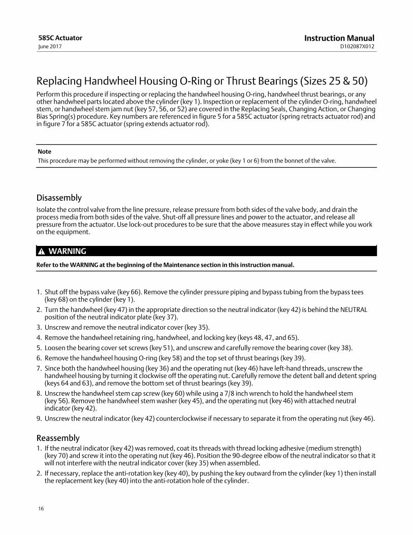
Replacing Handwheel Housing O‐Ring or Thrust Bearings (Sizes 25 & 50)Perform this procedure if inspecting or replacing the handwheel housing O‐ring, handwheel thrust bearings, or anyother handwheel parts located above the cylinder (key 1). Inspection or replacement of the cylinder O‐ring, handwheelstem, or handwheel stem jam nut (key 57, 56, or 52) are covered in the Replacing Seals, Changing Action, or ChangingBias Spring(s) procedure. Key numbers are referenced in figure 5 for a 585C actuator (spring retracts actuator rod) andin figure 7 for a 585C actuator (spring extends actuator rod).
Note
This procedure may be performed without removing the cylinder, or yoke (key 1 or 6) from the bonnet of the valve.
Disassembly
Isolate the control valve from the line pressure, release pressure from both sides of the valve body, and drain theprocess media from both sides of the valve. Shut‐off all pressure lines and power to the actuator, and release allpressure from the actuator. Use lock‐out procedures to be sure that the above measures stay in effect while you workon the equipment.
WARNING
Refer to the WARNING at the beginning of the Maintenance section in this instruction manual.
1. Shut off the bypass valve (key 66). Remove the cylinder pressure piping and bypass tubing from the bypass tees(key 68) on the cylinder (key 1).
2. Turn the handwheel (key 47) in the appropriate direction so the neutral indicator (key 42) is behind the NEUTRALposition of the neutral indicator plate (key 37).
3. Unscrew and remove the neutral indicator cover (key 35).
4. Remove the handwheel retaining ring, handwheel, and locking key (keys 48, 47, and 65).
5. Loosen the bearing cover set screws (key 51), and unscrew and carefully remove the bearing cover (key 38).
6. Remove the handwheel housing O‐ring (key 58) and the top set of thrust bearings (key 39).
7. Since both the handwheel housing (key 36) and the operating nut (key 46) have left‐hand threads, unscrew thehandwheel housing by turning it clockwise off the operating nut. Carefully remove the detent ball and detent spring(keys 64 and 63), and remove the bottom set of thrust bearings (key 39).
8. Unscrew the handwheel stem cap screw (key 60) while using a 7/8 inch wrench to hold the handwheel stem (key 56). Remove the handwheel stem washer (key 45), and the operating nut (key 46) with attached neutralindicator (key 42).
9. Unscrew the neutral indicator (key 42) counterclockwise if necessary to separate it from the operating nut (key 46).
Reassembly1. If the neutral indicator (key 42) was removed, coat its threads with thread locking adhesive (medium strength)
(key 70) and screw it into the operating nut (key 46). Position the 90‐degree elbow of the neutral indicator so that itwill not interfere with the neutral indicator cover (key 35) when assembled.
2. If necessary, replace the anti‐rotation key (key 40), by pushing the key outward from the cylinder (key 1) then installthe replacement key (key 40) into the anti‐rotation hole of the cylinder.

Instruction ManualD102087X012
585C ActuatorJune 2017
17
3. Lubricate the inside surface of the operating nut (key 46) with lithium grease (key 24). Install the operating nut withthe attached neutral indicator, and the handwheel stem washer (key 45), onto the handwheel stem (key 56) andsecure with the handwheel stem cap screw (key 60). Tighten the cap screw to 169 N�m (125 lbf�ft).
4. Place the bottom set of thrust bearings (key 39) on top of the cylinder (key 1). Insert the detent spring and ball (keys 63 and 64) into the cylinder.
5. Install the handwheel housing O‐ring (key 58) on the handwheel housing (key 36). Since both the handwheelhousing and the operating nut (key 46) have left‐hand threads, thread the handwheel housing onto the operatingnut by turning it counterclockwise over the operating nut until the handwheel housing is snug against the bottomset of thrust bearings (key 39).
6. Install the top set of thrust bearings (key 39) over the handwheel housing (key 36).
7. Carefully slide the bearing cover (key 38) over the handwheel housing (key 36) and thread the bearing cover handtight onto the cylinder (key 1). Secure by tightening the set screws (key 51) to 18 N�m (13 lbf�ft).
8. Install the locking key, handwheel, and handwheel retaining ring (keys 65, 47, and 48).
9. Screw the neutral indicator cover (key 35) hand tight only onto the handwheel housing (key 36).
10. Install the bypass tubing with attached bypass valve (key 66) into the bypass tees (key 68) in the cylinder (key 1).
Replacing Seals, Changing Action, or Changing Bias Spring(s) (Sizes 25 & 50)Key numbers are referenced in figures 4 and 5 for a 585C actuator (spring retracts actuator rod) and in figures 6 and 7for a 585C actuator (spring extends actuator rod).
Disassembly
Isolate the control valve from the line pressure, release pressure from both sides of the valve body, and drain theprocess media from both sides of the valve. Shut‐off all pressure lines and power to the actuator, release all pressurefrom the actuator, and release all bias spring compression force by slowly unscrewing the cylinder cover bolting in acrisscross pattern. Use lock‐out procedures to be sure that the above measures stay in effect while you work on theequipment.
WARNING
Refer to the WARNING at the beginning of the Maintenance section in this instruction manual.
For 585C actuators with push‐only handwheel, figure 8, be sure the handjack stem is backed out of the cylinder as faras it will go to relieve any extra spring compression.
1. Remove the cylinder pressure piping. With a handwheel construction, perform steps 1. through 2. of theReplacing Handwheel Housing O‐Ring or Thrust Bearings procedure.
Note
In the following step, loosen each cylinder‐to‐yoke cap screw a slight amount in turn in a crisscross pattern to keep the cylindersquare with the yoke while relieving spring precompression.
2. While carefully allowing bias spring precompression to be slowly released, remove the cylinder‐to‐yoke cap screwsand cylinder cover (keys 2 and 1).

Instruction ManualD102087X012
585C ActuatorJune 2017
18
CAUTION
When performing the following step, set the cylinder on a protective surface to prevent damage to the cylinder surfaces.
3. Remove the cylinder (key 1). Set the cylinder on a protective surface to prevent damage to the cylinder surfaces.With a handwheel construction, inspect the cylinder O‐ring (key 57) and replace it if necessary, applying lithiumgrease (key 24) to the replacement O‐ring.
4. Inspect the piston O‐ring (key 8) and replace, if necessary. If the only further maintenance to be performed isreplacement of the piston O‐ring, skip to step 3. of this procedure.
Note
585C actuators may be used with or without the bias springs. In the following procedures, references are made to the bias springs.If the bias springs are not used, disregard references to them when performing the maintenance procedures.
5. Perform one of the following disassembly procedures (a, b, c, d, or e, as appropriate):
a. For 585C actuators without handwheel (If the bias spring is present, it extends the piston rod.) (figure 6), removethe piston cap screw (key 4), piston (key 3), bias spring(s) (key 16 and/or key 17), and travel stop spacer (key 5).
b. For 585C actuators with handwheel (If the bias spring is present, it extends the piston rod.) (figure 7), remove thehandwheel stem (key 56) with attached piston stud (key 69), piston (key 3), bias spring(s) (key 16 and/or key 17),and travel stop spacer (key 5).
c. For 585C actuators without handwheel (If the bias spring is present, it retracts the piston rod.) (figure 4), removethe bias spring(s) (key 16 and/or key 17), piston cap screw (key 4), travel stop spacer (key 5) and piston (key 3).
d. For 585C actuators with handwheel (If the bias spring is present, it retracts the piston rod.) (figure 5), remove thebias spring(s) (key 16 and/or key 17), the handwheel stem (key 56) with attached piston stud (key 69), travelstop spacer (key 5), and piston (key 3).
e. For 585C actuators with push‐only handwheel (figure 8), remove the cotter pin and slotted nut (keys 73 and 72)and lift off the handwheel. Remove the jam nut (key 52). Remove the cap screws (key 60) and lift off thehandwheel housing (key 36). Back the handwheel stem (key 56) out of the housing. Inspect the O‐rings (keys 57and 58). Replace these parts as necessary.
6. If inspection or replacement of the actuator stem O‐ring or bearing (key 9 or 11) is necessary, perform steps 1. through 7. Otherwise skip to step 2. , being sure to comply with the note preceding step 2.
7. Loosen the two cap screws in the stem connector (key 14) and remove it. If the actuator is mounted on a valve,separate the actuator stem (key 10) from the valve plug stem. Remove the actuator from the valve.
8. To inspect the actuator stem bearing (key 11), actuator stem O‐ring (key 9), or backup ring (key 25, size 50 only)remove the actuator stem (key 10) from the yoke (key 6). Replace these parts if necessary. Apply lithium grease(key 24) to the replacement O‐ring or bearing and install it into the yoke.
Assembly1. Install the actuator stem through the yoke.
Note
Make certain the travel indicator scale (key 19) correctly matches the travel per the Parts List.

Instruction ManualD102087X012
585C ActuatorJune 2017
19
2. To achieve the desired construction (either a direct‐acting or a reverse‐acting 585C actuator), perform one of thefollowing assembly procedures (a, b, or c, as appropriate):
a. For 585C actuators (bias spring retracts the piston rod) (figures 4 and 5), center the inner bias spring, if used,(key 17 per table 6 or 7) around the center boss in the yoke (key 6). If used per table 6 or 7, center the outer biasspring (key 16) around the inner bias spring. The outer bias spring should be within the outer boss in the yoke.Put the travel stop spacer and the piston (keys 5 and 3) on the actuator stem. Apply lithium grease (key 24) tothe threads of the piston cap screw or piston stud (key 4 or 69). Insert the piston cap screw, or stud plus attachedhandwheel stem (key 56), through both the piston and travel stop spacer and into the actuator stem. Use awrench on the flats of the actuator stem to prevent it from turning. Tighten the piston cap screw, or stud plusattached handwheel stem, to 102 N�m (75 lbf�ft) for size 25 actuators or 136 N�m (100 lbf�ft) for size 50actuators.
b. For 585C actuators with push‐only handwheel (figure 8), lubricate the O‐rings and handjack stem threads withlithium grease. Install the O‐ring (key 57) and handjack stem (key 56), turning the screw into the housing as far aspossible. Place the O‐ring (key 58) over the housing and insert into the cylinder (key 1). Replace the cap screws(key 60) and tighten to 41 N�m (30 lbf�ft) on size 25 actuators or 81 N�m (60 lbf�ft) on size 50 actuators. Replacethe jam nut (key 52), handwheel (key 47), and slotted nut and cotter pin (keys 72 and 73).
c. For 585C actuators (bias spring extends the piston rod) (figures 6 and 7), put the piston (key 3) on the actuatorstem and the travel stop spacer (key 5) on the piston. Apply lithium grease (key 24) to the threads of the pistoncap screw or piston stud (key 4 or 69). Insert the piston cap screw, or stud plus attached handwheel stem (key56), through both the travel stop spacer and piston and into the actuator stem. Use a wrench on the flats of theactuator stem to prevent it from turning. Tighten the piston cap screw, or stud plus attached handwheel stem,to 102 N�m (75 lbf�ft) for size 25 actuators or 136 N�m (100 lbf�ft) for size 50 actuators. Center the inner biasspring, if used, (key 17 per table 4 or 5) around the travel stop spacer. If used per table 4 or 5, center the outerbias spring (key 16) around the inner bias spring. The outer bias spring should be within the outer boss on thepiston.
3. Install the piston O‐ring (key 8) if it was removed from the piston, and the yoke O‐ring (key 7, figure 4 or 6) if it wasremoved from the yoke (key 6). Apply lithium grease (key 24) to the wall of the cylinder (key 1) and carefully slidethe cylinder over the piston O‐ring. Be sure the cylinder pressure connection is aligned with the yoke pressureconnection. Square the cylinder in place over the yoke O‐ring.
4. Line up the cylinder holes with the yoke holes making sure for a handwheel construction that the anti‐rotationgroove in the handwheel stem (key 56) is aligned with the hole in the cylinder for the anti‐rotation key (key 40).
Note
When placing the cylinder on the yoke and tightening the cylinder‐to‐yoke bolts, be sure to keep the cylinder square and alignedwith the top of the yoke.
5. Lubricate the cylinder‐to‐yoke bolts (key 2) with lithium grease (key 24). In a criss cross pattern, alternately tighteneach cylinder‐to‐yoke bolt a slight amount so that the cylinder stays square with the yoke. When all cylindersurfaces are in contact with the yoke, tighten each cylinder‐to‐yoke bolt to 70 N�m (55 lbf�ft) for a size 25 or 95N�m (70 lbf�ft) for a size 50.
6. With a handwheel construction, perform steps 2. through 10. of the Replacing Handwheel Housing O‐ring orThrust Bearings procedure.
7. If the actuator will be mounted on a valve, perform the appropriate actuator mounting procedure. Otherwise, placethe stem connector nut (key 13), stem connector (key 12), two cap screws (key 14), two hex nuts (key 23) and hexnut (key 15) in a parts bag and attach the bag to the actuator yoke.

Instruction ManualD102087X012
585C ActuatorJune 2017
20
Maintenance (Sizes 60‐130)
WARNING
To avoid personal injury or property damage caused by cylinder fracture as a result of piston impact, install the stemconnector securely before supplying pressure to the positioner. Use only a regulator-controlled air supply to move theactuator piston so that you can install the stem connector. Do not use the positioner to move the actuator piston beforeinstalling the stem connector.
WARNING
Avoid personal injury from sudden release of process pressure or uncontrolled process fluid. Before starting disassembly:
� Do not remove the actuator from the valve while the valve is still pressurized.
� Always wear protective gloves, clothing, and eyewear when performing any maintenance operations to avoid personalinjury.
� Disconnect any operating lines providing air pressure to the actuator. Be sure the actuator cannot suddenly open orclose the valve.
� Use bypass valves or completely shut off the process to isolate the valve from process pressure. Relieve process pressureon both sides of the valve. Drain the process media from both sides of the valve.
� Vent the power actuator loading pressure.
� Use lock‐out procedures to be sure that the above measures stay in effect while you work on the equipment.
� The valve packing box may contain process fluids that are pressurized, even when the valve has been removed from thepipeline. Process fluids may spray out under pressure when removing the packing hardware or packing rings, or whenloosening the packing box pipe plug.
� Check with your process or safety engineer for any additional measures that must be taken to protect against processmedia.
Key numbers indicated refer to figures 9 through 12.
Isolate the control valve from the line pressure, release pressure from both sides of the valve body, and drain theprocess media from both sides of the valve. Shut‐off all pressure lines and power to the actuator, and release allpressure from the actuator. Use lock‐out procedures to be sure that the above measures stay in effect while you workon the equipment.
1. If positioner is not used, go to step 5. If positioner is used, shut off all pressure lines to the positioner then removeall tubing lines (cylinder, instrument and supply) from the positioner.
CAUTION
Do not use wrenches or other tools directly on the valve stem. Damage to the stem surface could result in subsequentdamage to the valve packing.
2. Remove the stem connector (key 12) and the piston rod boot (key 29) used to protect the lower end of the actuatorstem.
3. Remove the socket head cap screws that hold the cylinder (key 1) to the yoke (key 6).
CAUTION
Exercise care in the following step to prevent damage to the cylinder wall during removal of the cylinder from the yoke.

Instruction ManualD102087X012
585C ActuatorJune 2017
21
4. Insert a screwdriver in the two slots on the lower edge of the cylinder casting and pry the cylinder loose from theyoke. Remove the cylinder, being careful not to mar the cylinder wall.
5. The piston (key 3) and actuator stem (key 10) will come out with the cylinder. The piston can then be removed byforcing it out the open end of the cylinder.
6. Unscrew the seal bushing (key 110 or 26), in the upper end of the yoke (key 6).
7. With the unit disassembled, inspect all parts for excessive wear. Replace all worn O‐rings. Lubricate (key 24) asindicated on the assembly drawings. Apply sealant (key 70) as indicated on the assembly drawings.
8. When reassembling the actuator after the piston nut (key 4) has been removed from the actuator stem (key 10),clean the threads of the piston nut thoroughly and apply thread sealant to the threads. Tighten the piston nutsecurely to a torque of 237 N�m (175 lbf�ft) for size 60 actuators, 1290 N�m (950 lbf�ft) for size 68, 80, and 100actuators, or 2070 N�m (1530 lbf�ft) for size 130 actuators.
Side‐Mounted Handwheel Maintenance (Sizes 60‐130)Refer to figure 9 and 10.
1. The handwheel gears should be lubricated periodically. A grease fitting (key 140) is provided on sizes 80, 100, and130. On sizes 60 and 68, remove the handwheel (key 118) and the bevel pinion (key 116) and pack the gear casewith lithium grease. Loosen the set screw (key 139) before attempting to remove the pinion and extension.
2. If it is necessary to change the valve plug action from push‐down‐to‐close to push‐down‐to‐open or vice versa,change the handwheel arrangement so that the arrow indicates the correct rotation required to open the valve.
a. For sizes 60 and 68, remove the handwheel, invert and replace it. On sizes 60 and 68 (figure 9), remove andreplace the spring‐loaded ball assembly (key 123) in the opposite side.
b. For sizes 80‐100, remove the handwheel assembly and install in the opposite end of the gear case by unscrewingthe back and front worm retainers (keys 135 and 136, not shown) and turn the handwheel to disengage thebevel pinion (key 116).
Disassembly of Handwheel Constructions (Sizes 60 and 68)
WARNING
Refer to the WARNING at the beginning of the Maintenance section (Sizes 60‐130) in this instruction manual.
To disassemble 585C piston actuators sizes 60 and 68 (with handwheel) for maintenance, perform the followingprocedures (figure 9 and 10):
1. Be sure that all pressure is out of the cylinder and valve body.
2. Remove all tubing lines to the positioner.
3. Remove the cap screws (key 2) on the underside of either the cylinder flange (key 100) for size 60 or the adapterflange (key 76) for size 68. Remove the cylinder (key 1).
4. Remove the piston nut (key 4), then use a mallet to tap the piston (key 3) off the piston connector (key 107).
5. Remove the handwheel extension (key 117) by loosening the set screw (key 139) and unscrewing the extension.
6. Remove the cap screws (key 2) holding the cylinder flange (key 100) to the yoke (key 6).
7. Lift the cylinder flange (key 100) off the yoke (key 6).
8. Inspect the handwheel gears and bearings as needed.

Instruction ManualD102087X012
585C ActuatorJune 2017
22
9. To remove the actuator stem (not shown), loosen the stem connection (key 12) and pull the actuator stem out thetop of the sleeve assembly (key 104).
10. Remove the sleeve by screwing it out of the sleeve assembly (key 104).
11. Unscrew the seal bushing (key 110) to inspect the O‐rings (keys 9 and 27).
Disassembly of Handwheel Constructions (Sizes 80‐130)
WARNING
Refer to the WARNING at the beginning of the Maintenance section (Sizes 60‐130) in this instruction manual.
To disassemble 585C piston actuators sizes 80‐130 (with handwheel) for maintenance, perform the followingprocedures (figure 10):
1. Be sure that all pressure is out of the cylinder and valve body.
2. Remove all tubing lines to the positioner.
3. Remove the cap screws (key 2) on the underside of the cylinder adapter (key 101) and remove the cylinder (key 1).
4. Remove the piston nut (key 4), then use a mallet to remove the piston (key 3) from the piston connector (key 107).
5. Remove the cap screws (key 127) and cylinder adaptor (key 101).
6. Remove the cap screws (key 128) and remove the spacer (key 102), being careful not to lose the key (key 144).
7. Remove the locking pin (key 131), disconnect the stem connector (key 12) and pull out the actuator stem.
8. Remove the pointer (key 129) and turn the sleeve out of the sleeve assembly (key 104).
9. Remove the cap screws (key 128) holding the gear case (key 103) to the yoke (key 6).
10. Lift the gear case (key 103) to expose the handwheel assembly.
Reassembly (Sizes 60‐130)
When reassembling the 585C piston actuator with side‐mounted handwheel, adjust the setscrew (key 125) toeliminate play in gear bearings. When properly set, lock with key 126.
When reassembling the actuator after the piston nut (key 4) has been removed from the piston connector (key 107),clean the threads of the piston nut thoroughly and apply thread sealant to the threads. Tighten the piston nut securelyto a torque of 237 N�m (175 lbf�ft) for size 60 actuators, 1290 N�m (950 lbf�ft) for size 68, 80, and 100 actuators, or2070 N�m (1530 lbf�ft) for size 130 actuators.
Parts OrderingWhen corresponding with your Emerson sales office or Local Business Partner about this equipment, refer to the serialnumber found on the actuator nameplate (key 21).
WARNING
Use only genuine Fisher replacement parts. Components that are not supplied by Emerson Automation Solutions shouldnot, under any circumstances, be used in any Fisher valve, because they may void your warranty, might adversely affect theperformance of the valve, and could cause personal injury and property damage.

Instruction ManualD102087X012
585C ActuatorJune 2017
23
Parts KitsActuator Size Parts Kit Description Parts Kit Number
25 O‐ring (contains keys 7, 8, and 9)Backup ring (key 25) for size 50 actuators only
R585CX00252
50 R585CX00502
60 (2‐inch maximum travel)O‐ring (contains keys 7, 8, 9, and 27)Piston rod boot (key 29) and Snap ring (keys 30 and 31)
R585CX00012
60 (4‐inch maximum travel)O‐ring (contains keys 7, 8, 9, and 27)Piston rod boot (key 29) and Snap ring (keys 30 and 31)
R585CX00022
60 (2‐, 4‐, and 8‐inch maximum travel w/ handwheel)(8‐inch maximum travel)
O‐ring (contains keys 7, 8, 9, and 27) R585CX00032
68 (2‐, 4‐, and 8‐inch maximum travel w/ handwheel) O‐ring (contains keys 7, 8, 9, 27, and 112) R585CX00102
68 (2‐, 4‐, and 8‐inch maximum travel)80 (8‐inch maximum travel)80 (2‐, 4‐, and 8‐inch maximum travel w/ handwheel)
O‐ring (contains keys 7, 8, 9, and 27) R585CX00042
80 (4‐inch maximum travel)O‐ring (contains keys 7, 8, 9, and 27)Piston rod boot (key 29) and Snap ring (keys 30 and 31)
R585CX00052
100 (4‐inch maximum travel)O‐ring (contains keys 7, 8, 9, and 27)Piston rod boot (key 29) and Snap ring (keys 30 and 31)
R585CX00062
100 (8‐inch maximum travel)4‐ and 8‐inch maximum travel w/ handwheel)
O‐ring (contains keys 7, 8, 9, and 27) R585CX00072
130 (4‐inch travel)O‐ring (contains keys 7, 8, 9, and 27)Piston rod boot (key 29) and Snap ring (keys 30 and 31)
R585CX00082
130 (8‐inch travel) (4‐ and 8‐inch travel with handwheel)
O‐ring (contains keys 7, 8, 9, and 27) R585CX00092

Instruction ManualD102087X012
585C ActuatorJune 2017
24
Parts List
Note
Contact your Emerson sales office or Local Business Partner for Part
Ordering information.
Sizes 25 & 50
Common Actuator Parts (figure 4 or 6)Key Description
�1 Cylinder
�2 Cylinder‐to‐Yoke Bolts
�3 Piston, aluminum
�4 Cap Screw, for actuators without handwheel
�5 Travel Stop Spacer, aluminum
�6 Yoke, ductile iron
�7* Yoke O‐ring
�8* Piston O‐ring
�9* Actuator Stem O‐ring
10 Actuator Stem, chrome plated steel
11* Piston Stem Bearing, nylon
12 Stem Connector, zn pl steel
13 Stem Connector Nut
14 Cap Screw (2 req'd)
15 Hex Nut
16 Bias Spring, outer (steel) (see table 4‐7 for use)
17 Bias Spring, inner (steel) (see table 4‐7 for use)
18 Self Tapping Screw (2 req'd)
19 Travel Indicator Scale
20 Drive Screw, stainless steel (7 req'd)
21 Nameplate
22 Warning Tag, stainless steel
23 Hex Nut (2 req'd)
24 Lithium grease (not furnished with actuator)
25* Back‐Up Ring, Size 50 only (use with Nitrile or FKM O‐rings)
71 Warning Nameplate
75 Spacer (2 req'd)
Additional Parts for Actuator withHandwheel (figure 5 ,7, or 8)Key Description
�1 Cylinder,
35 Neutral Indicator Cover, polycarbonate
36 Handwheel Housing, cast iron
37 Neutral Indicator Plate, polycarbonate
38 Bearing Cover, cast iron
39 Thrust Bearing, chrome steel
40 Anti‐rotation Key, Zn pl steel
42 Neutral Indicator, stainless steel
43 Neutral Indicator Plate Screw, pl steel (2 req'd)
45 Handwheel Stem Washer, heat treated
46 Operating Nut
47 Handwheel, cast iron
48 Handwheel Retaining Ring, pl steel
50 Grease Fitting, Cd pl steel
51 Bearing Cover Set Screw, pl steel (3 req'd)
52 Handwheel Jam Nut, steel
53 Button Plug, plastic
56 Handwheel Stem, heat treated ENC 416 stainless steel
57* Cylinder Cover O‐Ring, nitrile - For Push Only
58* Handwheel Housing O‐Ring, nitrile - For Push Only
60 Handwheel Stem Cap Screw, Zn pl steel
(4 req'd for size 25), (3 req'd for size 50)
63 Detent Spring
64 Detent Ball, Cr pl steel
65 Locking Key, steel
66 Bypass Valve
67 Bypass Tubing
68 Bypass Tee
69 Piston Stud
70 Thread locking adhesive (medium strength) (not furnished with
actuator)
72 Hex Nut, Slotted
73 Cotter Pin
74 Elbow, Tube
*Recommended spare parts

Instruction ManualD102087X012
585C ActuatorJune 2017
25
Figure 4. Fisher 585C Size 25 and 50 Actuators (spring retracts actuator rod)
44B6335‐C
VIEW ASIZE 50
A
APPLY LUBNOTE:KEY NUMBERS 22 AND 71 NOT SHOWN

Instruction ManualD102087X012
585C ActuatorJune 2017
26
Figure 5. Fisher 585C Size 25 and 50 Actuators Handwheel Assembly (spring retracts actuator rod)
44B6330‐B
APPLY LUB
HANDWHEEL ASSEMBLY

Instruction ManualD102087X012
585C ActuatorJune 2017
27
Figure 6. Fisher 585CR Size 25 and 50 Actuators (spring extends actuator rod)
44B6319‐D
VIEW A SIZE 50APPLY LUBNOTE:KEY NUMBERS 22 AND 71 NOT SHOWN
A

Instruction ManualD102087X012
585C ActuatorJune 2017
28
Figure 7. Fisher 585CR Size 25 and 50 Actuators Handwheel Assembly (spring extends actuator rod)
44B6337‐C
APPLY LUB, SEALANT
HANDWHEEL ASSEMBLY

Instruction ManualD102087X012
585C ActuatorJune 2017
29
Figure 8. Fisher 585C Size 25 and 50 Actuators Handwheel Assembly—Direct Acting, Push Only(spring retracts actuator rod)
34B8587‐B
HANDWHEEL ASSEMBLY
APPLY LUB

Instruction ManualD102087X012
585C ActuatorJune 2017
30
Sizes 60‐130 (figures 9‐13)
Key Description
1 Cylinder Assembly, aluminum
2 Cap Screw, pl alloy steel
�Size 60,68, 80, and 100 - Hex Socket, 1.25 inch length
�Size 130 - Hex Socket, 1.75 inch length
3 Piston, aluminum
4 Piston Nut, pl steel
6 Yoke
7* O‐Ring, nitrile
8* O‐Ring, nitrile
9* O‐Ring, nitrile
10 Actuator Stem, S41600 Cr pl
12 Stem Connector Assembly, zinc‐plated steel
15 Hex Nut, pl steel
18 Screw (2 req'd)
19 Travel Indicator Scale, stainless steel
20 Drive Screw, stainless steel
21 Nameplate, stainless steel
22 Warning Nameplate (not shown)
24 Lithium grease (not furnished with actuator)
26* Lower Seal Bushing, brass
27* O‐Ring, nitrile
28* Wiper Scraper, vendor
29* Piston Rod Boot, neoprene
30* Snap Ring, pl steel
31* Snap Ring, pl steel
32 Travel Indicator Disk, S41300
33 Twin Speed Nut, stainless steel (not shown)
34 Machine Screw, pl steel
70 Thread locking adhesive (medium strength)
(not furnished with actuator)
76 Adaptor Flange, Class C cast iron
76 Cylinder Flange, cast iron
77 Cap Screws, pl steel
90 Pipe Nipple, S31600 (not shown)
91 Pipe Tee, S31600
92 Needle Valve
100 Cylinder Flange, cast iron
101 Cylinder Adaptor, A07130 aluminum
102 Spacer, cast iron
103 Gear Case, cast iron
104 Sleeve Assembly, S41600
105 Sleeve, S41600
Key Description
106 Actuator Stem, S41600
107 Piston Connector, S41600
108 Piston Ring Adaptor, S41600
109 Washer, steel
110* Upper Seal Bushing, brass
111 Retaining Ring, stainless steel
112* O‐Ring, nitrile, Size 68
113 Bearing Retainer, Class 30 cast iron
114 Bevel Gear, cast iron
114 Worm Gear, bronze
115 Thrust Bearing, carbon steel (2 req'd)
116 Bevel Pinion, S41600
116 Worm Shaft, steel
117 Extension, carbon steel
118 Handwheel, cast iron
119 Handwheel Cap, cast iron
119 Hex Nut, steel (1 req'd)
120 Lockwasher, carbon steel
121 Spring Cap, G12144 carbon steel
122 Spring, phos. bronze
123 Ball, steel
123 Cover Screw, steel
124 Combination Bearing, vendor
125 Set Screw, alloy steel
126 Hex Nut, steel
127 Cap Screw, steel
�Hex head, 1.50 inch length
128 Cap Screw, steel
�Hex head, 1.75 inch length
129 Pointer, S41600
130 Handjack Indicator, stainless steel
131 Locking Pin, S41600
132 Chain, stainless steel
133 Drive Screw, carbon steel
134 Ball Bearing, steel
135 Front Worm Retainer, steel
136 Back Worm Retainer, steel
137 Hand Grip, G12144 carbon steel
138 Hand Grip Bolt, steel
139 Set Screw, steel
140 Zerk Fitting, steel
141 Ring, carbon steel
142 Machine Screw, carbon steel (2 req'd)
143 Key, S41600
144 Key, G10180 carbon steel
145 Caution Tag (not shown)
146 Cable Tie (2 Req'd) (not shown)
*Recommended spare parts

Instruction ManualD102087X012
585C ActuatorJune 2017
31
Figure 9. Fisher 585C Actuator with Integral Handjack Size 68 with 2‐ and 4‐Inch Travel
58B1370‐A
APPLY LUB/SEALANTPARTS NOT SHOWN: 33, 145, 146 FOR BYPASS ASSEMBLY, SEE FIGURE 13

Instruction ManualD102087X012
585C ActuatorJune 2017
32
Figure 10. Fisher 585C Actuator with Integral Handjack Size 80 and 100 with 4‐Inch Travel
58B1373‐A
PARTS NOT SHOWN: 141, 145, 146FOR BYPASS ASSEMBLY, SEE FIGURE 13
SECTION A—A
A A
APPLY LUB/SEALANT

Instruction ManualD102087X012
585C ActuatorJune 2017
33
Figure 11. Fisher 585C Actuator Size 60 with 2‐ and 4‐Inch Travel
58B1365‐A
PARTS NOT SHOWN: 33
APPLY LUB/SEALANT

Instruction ManualD102087X012
585C ActuatorJune 2017
34
Figure 12. Fisher 585C Actuator Size 60 with 8‐Inch Travel and Size 68 with 2‐, 4‐, and 8‐Inch Travel
PARTS NOT SHOWN: 33
APPLY LUB/SEALANT
58B1366‐A

Instruction ManualD102087X012
585C ActuatorJune 2017
35
Figure 13. Fisher 585C Size 60‐130 Bypass Assembly
38B1397/A

Instruction ManualD102087X012
585C ActuatorJune 2017
36
Emerson Automation SolutionsMarshalltown, Iowa 50158 USASorocaba, 18087 BrazilCernay, 68700 FranceDubai, United Arab EmiratesSingapore 128461 Singapore
www.Fisher.com
The contents of this publication are presented for informational purposes only, and while every effort has been made to ensure their accuracy, they are notto be construed as warranties or guarantees, express or implied, regarding the products or services described herein or their use or applicability. All sales aregoverned by our terms and conditions, which are available upon request. We reserve the right to modify or improve the designs or specifications of suchproducts at any time without notice.
� 2005, 2017 Fisher Controls International LLC. All rights reserved.
Fisher, FIELDVUE, and TopWorx are marks owned by one of the companies in the Emerson Automation Solutions business unit of Emerson Electric Co.Emerson Automation Solutions, Emerson, and the Emerson logo are trademarks and service marks of Emerson Electric Co. All other marks are the propertyof their respective owners.
Neither Emerson, Emerson Automation Solutions, nor any of their affiliated entities assumes responsibility for the selection, use or maintenanceof any product. Responsibility for proper selection, use, and maintenance of any product remains solely with the purchaser and end user.