www.Fisher.com
Fisher™ 2500‐249 Pneumatic Controllers andTransmittersTypical caged and cageless sensor/instrumentconfigurations are shown below and in figure 1. Cagedsensors (figure 2) provide more stable operation thando cageless sensors (figure 3) for vessels with internalobstructions or considerable internal turbulence.Cageless sensors are generally used on specific gravityand interface control applications requiring largedisplacers that are more easily accommodated byflange connections up to NPS 8. The availability ofmany different displacer stem lengths permitslowering the displacer down to the mostadvantageous depth in the vessel.
Fisher pneumatic controllers and transmitters are usedwherever rugged, dependable, and simply constructeddisplacer‐style pneumatic instrumentation is requiredin liquid level, interface level, or density service. Theruggedness of these products is demonstrated by theiruse in many kinds of demanding applications,including those in the power, chemical process, oil andgas production, and petrochemical industries.
STANDARD CAGED SENSORSMOUNT ON VESSEL SIDE
WITH DISPLACER INSIDE CAGE
W8334
W9354‐1
FISHER 2500 CONTROLLER INCOMBINATION WITH A 249W SENSOR CAN
MOUNT ON VESSEL TOP OR BE INSTALLED INA CUSTOMER‐SUPPLIED CAGE
W8679
CAGELESS SENSORS CAN MOUNTON VESSEL SIDE OR TOP WITH
DISPLACER INSIDE VESSEL
2500-249 Controllers and TransmittersD200037X012
Product Bulletin34.2:2500April 2018
2500-249 Controllers and TransmittersD200037X012
Product Bulletin34.2:2500April 2018
2
Specifications
Available Configurations
See tables 1, 5, and 6
Input Signal
Fluid Level or Fluid‐to‐Fluid Interface Level: From 0 to100 percent of displacer length—standard lengths forall sensors are � 356 mm (14 inches) or � 813 mm(32 inches); other lengths available depending onsensor constructionFluid Density: From 0 to 100 percent of displacementforce change obtained with given displacervolume—standard volumes are� 980 cm3 (60 inches3) for 249C and 249CP sensorsor � 1640 cm3 (100 inches3) for most other sensors;other volumes available depending upon sensorconstruction
Allowable Specific Gravity
Specific gravity with standard volume displacers andstandard wall torque tubes:Fluid Level and Fluid‐to‐Fluid Interface2500 Controllers, except 2503 and 2503R: Specificgravity range, 0.20 to 1.102503 and 2503R: Specific gravity range, 0.25 to 1.10Fluid Density2500 Controllers, except 2503 and 2503R: Minimumchange in specific gravity, 0.202503 and 2503R: Minimum change in specific gravity,0.25
Contact your Emerson sales office or Local BusinessPartner for information on non‐standard applications
Output Signal
See table 1
Output Action
� �Direct (increasing fluid or interface level or specificgravity increases output pressure) or� �Reverse (increasing fluid or interface level orspecific gravity decreases output pressure)
Area Ratio of Relay Diaphragms
3:1
Supply Pressure(1)
Normal Operation: See table 4.
Maximum to Prevent Internal Part Rupture(2):3 bar (45 psig)
Steady‐State Air Consumption
See table 4
Proportional Band, Differential Gap, or Span
See table 1
Set Point (Controllers Only)
Continuously adjustable to position control point ordifferential gap of less than 100 percent anywherewithin displacer length (fluid or interface level) ordisplacement force change (density)
Zero Adjustment (Transmitters Only)
Continuously adjustable to position span of less than100 percent anywhere within displacer length (fluidor interface level) or displacement force change(density)
Performance
Independent Linearity (Transmitters Only):1 percent of output pressure change at span of 100percentHysteresis: 0.6 percent of output pressure change at100 percent of proportional band, differential gap, orspanRepeatability: 0.2 percent of displacer length ordisplacement force changeDeadband (Except Differential Gap Controllers(3)):0.05 percent of proportional band or spanTypical Frequency Response: 4 Hz and 90‐degreephase shift at 100 percent of proportional band,differential gap, or span with output piped to typicalinstrument bellows using 6.1 meters (20 feet) of 6.4mm (1/4‐inch) tubingAmbient Temperature Error: ±1.5 percent of outputpressure change per 28�C (50�F) of temperaturechange at 100 percent of proportional band,differential gap, or span when using sensor withstandard wall N05500 torque tubeReset (Proportional‐Plus‐Reset Controllers Only):Continuously adjustable from 0.005 to over 0.9minutes per repeat (from 200 to under 1.1 repeatsper minute)Anti‐Reset Differential Relief (2502F and 2502FRControllers Only): Continuously adjustable from 0.14to 0.48 bar (2 to 7 psi) differential to relieve excessivedifference between proportional and reset pressures
‐continued‐

2500-249 Controllers and TransmittersD200037X012
Product Bulletin34.2:2500April 2018
3
Specifications (Continued)
Standard Tubing Connections
1/4 NPT internal
Sensor Connection Sizes
See tables 5 and 6
Maximum Working Pressures (Sensors Only)(1)
Consistent with applicable ASMEpressure/temperature ratings for the specific sensorconstructions shown in tables 5 and 6
Operative Ambient Temperatures(1)
Controller.� Standard: -40 to 71�C (-40 to 160�F)� High Temperature: -18 to 104�C (0 to 220�F)
Sensor.See table 2For ambient temperature ranges, guidelines, and useof optional heat insulator, see figure 4
Standard Supply and Output Pressure GaugeIndications
See table 4
Allowable Process Temperatures(1)
See table 2
Hazardous Area Classification
2500 controllers comply with the requirements ofATEX Group II Category 2 Gas and Dust
Meets Customs Union technical regulation TP TC012/2011 for Groups II/III Category 2 equipment
II Gb c T*XIII Db c T*X
Construction Materials
See tables 2, 3, and 7
Mounting Positions
See figure 9
Caged Sensor Connection Styles
See figure 10
Options
See Options section
NOTE: Specialized instrument terms are defined in ANSI/ISA Standard 51.1 - Process Instrument Terminology.1. The pressure/temperature limits in this document and any applicable code or standard should not be exceeded.2. Also see Supply Pressure Overpressure Protection section.3. For 2500S, 2500SC, and 2503 adjusting the differential gap is equivalent to adjusting the deadband.
Table of ContentsSpecifications 2. . . . . . . . . . . . . . . . . . . . . . . . . . . . . . . .Features 5. . . . . . . . . . . . . . . . . . . . . . . . . . . . . . . . . . . . .Supply Pressure Overpressure Protection 10. . . . . . . .Principle of Operation 10. . . . . . . . . . . . . . . . . . . . . . . .
Proportional Controller or Transmitter 11. . . . . . . . .Proportional-Plus-Reset Controller 11. . . . . . . . . . . .Anti-Resetup Windup 12. . . . . . . . . . . . . . . . . . . . . . .
On-Off Controller With Proportional Valve 12. . . . . .On-Off Controller Without Proportional Valve 12. . .
Options 12. . . . . . . . . . . . . . . . . . . . . . . . . . . . . . . . . . . .Installation 12. . . . . . . . . . . . . . . . . . . . . . . . . . . . . . . . .Ordering Information 15. . . . . . . . . . . . . . . . . . . . . . . . .Construction 15. . . . . . . . . . . . . . . . . . . . . . . . . . . . . . . .

2500-249 Controllers and TransmittersD200037X012
Product Bulletin34.2:2500April 2018
4
Table 1. Additional Specifications for Selected Fisher 2500 Controller ConfigurationsControl or Transmission Mode Controller(1) Full Output Signal Change Obtainable Over Input Of: Output Signal
Proportional control 2500, 2500C(2) Proportional band of 0 to 100 percent of displacer length or
displacement force change (10 to 100 percent recommended) 0.2 to 1.0 bar(3 to 15 psig) or0.4 to 2.0 bar(6 to 30 psig)
Proportional‐plus‐reset control 2502, 2502C(2)
Proportional band of 0 to 200 percent of displacer length or
displacement force change (20 to 200 percent recommended)Proportional‐plus‐reset control with
anti‐reset windup2502F
Differential
Gap (On‐off)
Control
With proportional valve
and full differential
gap adjustment2500S, 2500SC(2) Differential gap of 0 to 100 percent of displacer length
0 and 1.4 bar
(0 and 20 psig) or
0 and 2.4 bar
(0 and 35 psig)
Without proportional
valve - has limited
differential gap
adjustment
2503
Differential gap of approximately 25 to 40 percent of displacer
length, when a 356 millimeter (14-inch) ideal‐volume displacer is
used on 1.0 specific gravity liquid level service and a standard 1.4
bar (20 psig) supply regulator setting is varied between 1.0 and 1.7
bar (15 and 25 psig)(3)
0 and full supply
pressure(4)
Proportional transmission 2500T, 2500TC(2) Span of 0 to 100 percent of displacer length or displacement force
change (20 to 100 percent recommended)
0.2 and 1.0 bar
(3 to 15 psig) or
0.4 to 2.0 bar
(6 to 30 psig)
1. The suffix R is added to the type number for reverse action, and all types have a 67CFR supply regulator mounted as standard.2. The suffix C is added to the type number for indicator assembly.3. Other displacer lengths and volumes, or service conditions, will result in other differential gaps.4. 1.4 bar (20 psig) and 2.4 bar (35 psig) are the standard factory‐set supply regulator pressures, but these values will vary whenever the supply pressure is changed to adjust the differential gap.
Table 2. Allowable Process Temperatures forCommon Fisher 249 Sensor Component Materials
MATERIALPROCESS TEMPERATURE
Minimum Maximum
Cast Iron(1) -29�C (-20�F) 232�C (450�F)
Steel -29�C (-20�F) 427�C (800�F)
Stainless Steel -198�C (-325�F) 427�C (800�F)
N04400 -198�C (-325�F) 427�C (800�F)
Aluminum -195�C (-320�F) 99�C (210�F)
GasketsGraphite Laminate/SSTN04400/PTFESoft Iron Gasket
-198�C (-325�F)-73�C (-100�F)-29�C (-20�F)
427�C (800�F)204�C (400�F)427�C (800�F)
BoltingB7 steelB7M steelB8M stainless steel
-46�C (-50�F)-29�C (-20�F)
-198�C (-325�F)
427�C (800�F)427�C (800�F)427�C (800�F)
1. Cast iron may be used to -73�C (-100�F) provided a heat insulator is used below-18�C (0�F) and stainless steel studs and nuts are used below -46�C (-50�F).
Table 3. Displacer and Torque Tube MaterialsPart Standard Material Other Material
Displacer 304 Stainless Steel
316 Stainless Steel,N10276, N04400,Plastic, and SpecialAlloys
Displacer Stem,Driver Bearing,Displacer Rod and Driver
316 Stainless Steel
N10276, N04400,other AusteniticStainless Steels, andSpecial Alloys
Torque Tube N05500(1) 316 Stainless Steel,N06600, N10276
1. N05500 is not recommended for spring applications above 232�C(450�F). Contact your Emerson sales office, Local Business Partner, orapplication engineer if temperatures exceeding this limit are required.

2500-249 Controllers and TransmittersD200037X012
Product Bulletin34.2:2500April 2018
5
Table 4. Supply Pressure Data
OUTPUT SIGNALSTANDARD SUPPLY AND OUTPUTPRESSURE GAUGE INDICATIONS(1)
NORMAL OPERATINGSUPPLY PRESSURE(2)
AIR CONSUMPTION AT NORMAL OPERATING SUPPLY PRESSURE(3)
Normal m3/h(6) Scfh(6)
Bar Psig Min(4) Max(5) Min(4) Max(5)
0.2 to 1.0 bar (3 to 15 psig),
except 0 and 1.4 bar (0 and 20
psig)(2) for on‐off controllers0 to 30 psig 1.4 20 0.11 0.72 4.2 27
0.4 to 2.0 bar (6 to 30 psig),
except 0 and 2.4 bar (0 and 35
psig)(2) for on‐off controllers0 to 60 psig 2.4 35 0.19 1.1 7 42
1. Consult your Emerson sales office or Local Business Partner about gauges in other units.2. Control and stability may be impaired if this pressure is exceeded (except 2503 or 2503R controller without proportional valve).3. Except 2503 or 2503R controller, which bleeds only when relay is open at exhaust position.4. At zero or maximum proportional band or span setting.5. At setting in middle of proportional band or span range.6. Normal m3/hr=normal cubic meters per hour at 0�C and 1.01325 bar. Scfh=standard cubic foot per hour at 60�F and 14.7 psia.
Features� Easy Adjustment—Set point, proportional valve
opening, and reset changes are made with simpledial‐knob controls.
� Simple, Durable Construction—Few moving partsare used. Knife‐edged driver bearing in sensor andplated brass instrument case ball bearing for torquetube rotary shaft help provide low‐frictionoperation. Sensors are available in ratings up toCL2500.
� Mounting Versatility—Caged sensors are available ina variety of orientations and connection styles, andall sensors can be either right‐ or left‐handmounted.
� Sensitive to Small Changes—Displacer reaction tosmall specific gravity changes allows theseinstruments to be used for density applications andin other applications where a response to low levelsof input signal change is required.
� Easy Reversibility—Action is field reversible fromdirect to reverse or vice versa without additionalparts.
� Reduced Maintenance Costs—Spring‐out wireprovides for in‐service cleaning of relay orifice(figure 1). Torque tube can be replaced withoutremoving torque tube arm.
� Reduced Operating Costs—Supply pressureconservation is enhanced in all constructionsbecause relay exhaust opens only when outputpressure is being reduced.
� Smaller Vessel Sizes Required for StableControl—Caged 249 sensors come standard with aliquid damping orifice in the lower equalizingconnection that helps stability where vesselcapacitance is small and permits narrowerproportional valve settings.

2500-249 Controllers and TransmittersD200037X012
Product Bulletin34.2:2500April 2018
6
Figure 1. Typical Fisher 2500 Controller Constructions with Right‐Hand Mounting Shown
DETAIL OF REVERSE‐ACTING 2503RON‐OFF CONTROLLER
DETAIL OF DIRECT ACTING 2502PROPORTIONAL‐PLUS RESET CONTROLLER
INDICATOR ASSEMBLY DETAILDIRECT‐ACTING 2500 CONTROLLER
RESET ADJUSTMENT
3‐WAY BOURDON TUBE VALVE HAS LARGEPORTS WHICH GREATLY REDUCE CLOGGING
PIPE PLUG INSTEAD OF PROPORTIONALVALVE MEANS INTERMITTENT BLEED THATMINIMIZES FREEZE UP
SPRING‐OUTCLEANING WIRE
PROPORTIONAL BANDADJUSTMENT
POINTER
INDICATOR ANDBASE PLATES
W5637
W0656‐1
W0648‐1
W0671‐1

2500-249 Controllers and TransmittersD200037X012
Product Bulletin34.2:2500April 2018
7
W0144-1
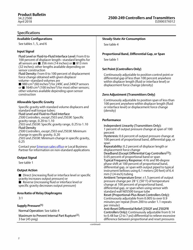
DAMPING ORIFICE(REMOVABLE IF CLOGGING WILL OCCUR)
W1800‐1
W2141‐1
KNIFE EDGE BEARING
TORQUE TUBE
DISPLACER ROD
ROTATABLEHEAD
DISPLACER
CAGE
Figure 2. Fisher 249B Caged Sensor (Typicalof all Rotatable‐Head Caged Sensors)
Figure 3. Typical Cageless Sensors
DISPLACER ROD
DISPLACER STEM ENDCONNECTOR
OPTIONALTRAVELSTOP PINAND PLATE
DISPLACERSTEM
DISPLACERSTUD
249BP MOUNTS ONTOP OF VESSEL
W0660‐1
249VS MOUNTS ONSIDE OF VESSEL
STANDARD TRAVEL STOP ASSEMBLY
249W WAFER BODY NPS 3 OR 4RF FLANGE
STILLWELL 1
Note: 1 Stillwell required around displacer if the fluid is ina state of continuous agitation
W8252
CENTER OF DISPLACERSHOULD BE LOCATIONOF LIQUID OR INTERFACELEVEL DURING NORMALOPERATION
249W MOUNTS ON TOP OF VESSEL AS SHOWN OR CANMOUNT IN CUSTOMER FABRICATED CAGE
W9353
2500-249 Controllers and TransmittersD200037X012
Product Bulletin34.2:2500April 2018
8
Table 5. Caged Displacer Sensors(1)
SENSOREQUALIZING CONNECTION
PRESSURE RATING(2)Style Size (NPS)
Torque tube
arm rotatable
with respect
to equalizing
connections
249(3)Screwed 1‐1/2 or 2
CL125 or 250Flanged 2
249B or 249BF(4)
Screwed or optional socket weld 1‐1/2 or 2 CL600
Raised face or optional ring‐type joint flanged1‐1/2 CL150, 300, or 600
2 CL150, 300, or 600
249C(2)
Screwed 1‐1/2 or 2 CL600
Raised face1‐1/2 CL150, 300, or 600
2 CL150, 300, or 600
249K Raised face or optional ring‐type joint flanged 1‐1/2 or 2 CL1500
249L Ring‐type joint flanged 2(5) CL2500
1. Standard displacer lengths for all styles (except 249) are 14, 32, 48, 60, 72, 84, 96, 108, and 120 inches. The 249 uses a displacer with a length of either 14 or 32 inches.2. PN flange connections available in EMA (Europe, Middle East, and Africa).3. Not available in EMA.4. 249BF available in EMA only. Also available in EN size DN 40 with PN 10 to PN 100 flanges and size DN 50 with PN 10 to PN 63 flanges.5. Top connection is NPS 1 ring‐type joint flanged for connection styles F1 and F2.
Table 6. Cageless Displacer Sensors(1)
Mounting Sensor Flange Connection (Size) Pressure Rating(2)
Mounts on top of vessel249BP(3)
NPS 4 raised face or optional ring‐type joint CL150, 300, or 600
NPS 6 or 8 raised face CL150 or 300
249CP NPS 3 raised face CL150, 300, or 600
Mounts on top of vessel 249P(4)NPS 4 raised face or optional ring‐type joint
CL900 or 1500
(EN PN 10 to DIN PN 250)
NPS 6 or 8 raised face CL150, 300, 600, 900, 1500, or 2500
Mounts on side of vessel 249VSFor NPS 4 raised face or flat face
CL125, 150, 250, 300, 600, 900, or 1500
(EN PN 10 to DIN PN 160)
For NPS 4 butt weld end, XXS CL2500
Mounts on top of vessel or on
customer supplied cage249W For NPS 3 or 4 raised face CL150, 300, or 600
1. Standard displacer lengths are 14, 32, 48, 60, 72, 84, 96, 108, and 120 inches.2. PN flange connections available in EMA (Europe, Middle East, and Africa).3. Not available in EMA.4. 249P with NPS 6 and 8 flanges and PN flanges are available in EMA only.
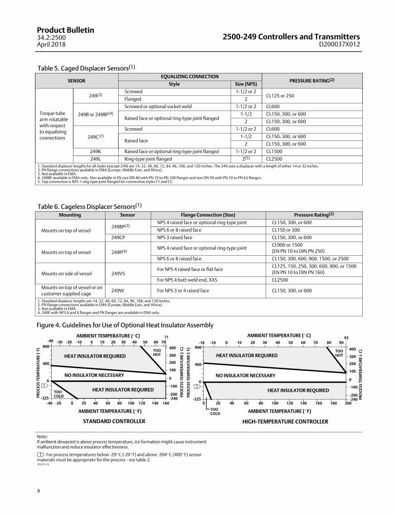
Figure 4. Guidelines for Use of Optional Heat Insulator Assembly
Note: If ambient dewpoint is above process temperature, ice formation might cause instrumentmalfunction and reduce insulator effectiveness.
1 For process temperatures below -29�C (-20�F) and above 204�C (400�F) sensor materials must be appropriate for the process - see table 2.
80 90
0 20 40 60 80 100 120 140 160
-40 70
71
400
300
200
100
00
400
800
-325 -240
NO INSULATOR NECESSARY
AMBIENT TEMPERATURE (�C)
STANDARD CONTROLLER
AMBIENT TEMPERATURE (�F)
HEAT INSULATOR REQUIREDTOOHOT
PR
OC
ES
S T
EM
PE
RA
TU
RE
( C
)
PR
OC
ES
S T
EM
PE
RA
TU
RE
( F
)
�
0 20 40 60 80 100 120 140 200
0 10 20-18 -10 30 40 50 60 7093
400
300
200
100
00
400
800
-325
NO INSULATOR NECESSARY
AMBIENT TEMPERATURE (�C)
HIGH‐TEMPERATURE CONTROLLER
AMBIENT TEMPERATURE (�F)
HEAT INSULATOR REQUIREDTOOHOT
PR
OC
ES
S T
EM
PE
RA
TU
RE
( C
)
PR
OC
ES
S T
EM
PE
RA
TU
RE
( F
)
180160
1 -100
-200
-40 -20
1
-240
-100
-200HEAT INSULATOR REQUIRED
TOO COLD
TOO COLD
HEAT INSULATOR REQUIRED
0 10 20-20 -10 30 40 50 60-30
��
�
B1413-1A

2500-249 Controllers and TransmittersD200037X012
Product Bulletin34.2:2500April 2018
9
Table 7. Construction MaterialsPart Sensor Material
In contactwith process
Cage, head,torque tube arm
249 Cast iron
249B, 249BF(1) Carbon steel
249C and 249CP CF8M (316 stainless steel) standard,CF3M (316L stainless steel),CF8 (304 stainless steel), CF3 (304L stainless steel),LCC (steel), C5 (steel),LC3 (3.5 percent nickel steel), M35‐1,CN7M (Alloy 20)
249K Steel standard, CF8, CF8M, CF3M, LCC, C5,LC3, WC1 (chrome moly steel), M35‐1, CN7M optional
249L Steel standard, CF8M, C5, WC1, LCC
249BP Carbon Steel
249P Carbon Steel
249VS LCC, WCC (steel), CF8M
Wafer body,torque tube arm
249W NPS 3NPS 4
WCC, CF8MLCC, CF8M
Torque tube 249, 249B, 249BF(1),249K, 249L,249P, 249VS, 249W
N05500 standard
249C, 249CP,stainless steel 249VS,249W
S31600 (316 stainless steel) standard
All S30403 (304L stainless steel), S31603 (316L stainless steel),N06600, N08020 (Alloy 20) optional
Displacer 249, 249B, 249BF(1),249K, 249VS, 249W
S30400 (304 stainless steel) standard
249C, 249CP, 249W S31600 (316 stainless steel) standard
249L A91100F (solid aluminum) standard
All Solid PTFE, N04400 or other special materials
Standard trim(2) All S31600
Bolting All Steel grade B7 studs or cap screws and grade 2H nuts (standard),steel grade B7M studs and grade 2M nuts optional on 249B and WCC 249W sensor
Standard torquetube end gasket
All 316 stainless steel/graphite laminate, except 304 stainless steel/graphite laminate for 249K sensor
Standard torquetube arm andcage gasket, if used
All Composition, except soft iron for the 249L sensor
Optional trimand gasketing
All 316 stainless steel trim with 316L stainless steel gasketingor soft iron gasketing; 317 stainless steel or N06600 trim with compositiongasketing; 304, 304L or 316L stainless steel, N04400 or N08020 trim and gasketing
In contact withsupply pressure
Bourdon tube or bellows Brass, plus SST 3‐way valve for 2503 or 2503R controller
Tubing Stainless steel
Relay diaphragms Nitrile (standard) or polyacrylate (high‐temperature)
Relay O‐ring Nitrile
Gasketing Chloroprene (standard) or rubber (high‐temperature)
Seal ring O‐rings (and reset reliefvalve O‐rings if used)
Nitrile (standard) or fluorocarbon (high‐temperature)
Other Case Aluminum
Cover Aluminum with glass gauge windows and nitrile cover gasket
Retaining flange Steel
1. Available only in EMA.2. Trim parts include displacer rod, driver bearing; displacer stem parts, and stem connection parts.

2500-249 Controllers and TransmittersD200037X012
Product Bulletin34.2:2500April 2018
10
Figure 5. Schematic of Direct‐Acting Fisher 2500‐249 Proportional Controller (or Transmitter) Shown withRight‐Hand Mounting
CD2114‐EB2296
OUTERBOURDONTUBECHANNEL
INNER BOURDONTUBE CHANNEL
SETPOINT OR ZERO ADJUSTMENT
FLAPPER
TORQUE TUBE SHAFT
EXHAUST
PROPORTIONAL VALVE
TO OTHERPNEUMATIC INSTRUMENTIF TRANSMITTERCONSTRUCTION ORAPPLICATIONSMALL
DIAPHRAGM
SUPPLY END OFRELAY VALVE
EXHAUST END OF RELAY VALVE
NOZZLE
FIXEDORIFICE EXHAUST
SUPPLYPRESSURE
LARGEDIAPHRAGM
SUPPLY PRESSURE
NOZZLE PRESSURE
OUTPUT PRESSURE
PROPORTIONAL PRESSURE
Supply PressureOverpressure ProtectionApplying excessive pressure to any portion of acontroller, transmitter or connected equipment maycause leakage, part damage, or personal injury due tobursting of pressure‐containing parts. Although thestandard 67CFR supply regulator for 2500 instrumentshas internal relief to provide very limited overpressureprotection, complete overpressure protectionbetween the supply regulator outlet and theinstrument case is needed if a malfunctioning supplyregulator can deliver a supply pressure that exceeds3.4 bar (50 psig).
Principle of OperationAll 2500 controllers and transmitters use the samebasic pressure‐balanced relay with a yokeddouble‐diaphragm assembly. Supply pressure eitherpasses through the fixed orifice and bleeds out thenozzle (figure 5 or 6) or directly enters the Bourdontube valve (figure 7). Nozzle pressure registers on thelarge relay diaphragm, and output pressure on thesmall relay diaphragm.
The following descriptions show how the variouscontroller and transmitter constructions work inconjunction with displacer action.

2500-249 Controllers and TransmittersD200037X012
Product Bulletin34.2:2500April 2018
11
Figure 6. Schematic of Direct‐Acting Proportional‐Plus‐Reset Controller
PROPORTIONALBELLOWS
TORQUE TUBE SHAFT SET POINTADJUSTMENT
RESET VALVE
PROPORTIONALVALVE
EXHAUST TO PROPORTIONALBELLOWS
TO RESET BELLOWS
SUPPLY PRESSURE
OUTPUT PRESSURE
NOZZLE PRESSURE
PROPORTIONALPRESSURERESET PRESSURE
WITH ARROW DOWN‐RELIEVES ONDECREASING OUTPUT(OUTPUT AT SUPPLYDURING SHUTDOWN)
DIFFERENTIALRELIEF VALVE
FROMRELAY
PROPORTIONBAND ADJUSTMENT
RESETADJUSTMENT
CJ4081‐AB2347‐2E0792 PROPORTIONAL‐PLUS‐RESET CONTROL
WITH ANTI‐RESET WINDUP
Proportional Controller orTransmitter
As long as the process remains constant, the displacerwill hold the torque tube shaft and attached flappersteady in relation to the nozzle. The nozzle‐flapperopening will be such as to permit pressure to bleedfrom the nozzle as fast as it enters through the fixedorifice of the relay, keeping the pressure loading onthe large relay diaphragm at the amount necessary tobalance the output pressure loading on the small relaydiaphragm.
A process variable change (such as a variation indownstream demand that affects liquid outflow andthus the level of the tank shown in figure 5) changesthe buoyant force acting on the displacer and movesthe flapper with respect to the nozzle. An increasingbuoyant force with direct action, or decreasingbuoyant force with reverse action, produces anozzle‐flapper restriction that increases nozzlepressure on the large relay diaphragm. This opens thesupply end of the relay valve and increases relayoutput pressure. But a decreasing buoyant force withdirect action, or increasing buoyant force with reverse
action, produces a nozzle‐flapper opening that bleedsoff nozzle pressure on the large relay diaphragm andopens the exhaust end of the relay valve to let outputpressure (and thus actuator loading pressure) bleedaway. The relay diaphragm pressure differentialequalizes and a new output pressure is maintainedaccording to the change in displacer position.
Proportional‐Plus‐Reset Controller
All 2502 controllers (figure 6) have a two‐way resetrestriction valve that channels proportional pressureinto a reset bellows to oppose proportional bellowsaction. This automatically slows the canceling effect ofany proportional action by a set amount per timeinterval, as long as there is a deviation from the controlpoint. Action of this reset pressure occurs on a delayedbasis, and the reset valve can be adjusted to vary thetime of delay.
If a prolonged difference exists between the set pointand the process variable, output pressure with aproportional‐plus‐reset controller will either drop tozero or rise to the maximum delivered by the supplyregulator. This condition is called reset windup.

2500-249 Controllers and TransmittersD200037X012
Product Bulletin34.2:2500April 2018
12
Anti‐Reset Windup
2502F and 2502FR controllers additionally haveanti‐reset windup to minimize the delay in returningthe controlled variable to the set point. This capabilityis provided by a reversible differential relief valve withadjustable spring. As shown in figure 6, proportionalpressure registers rapidly on the spring side of therelief valve diaphragm as well as in the proportionalbellows. Reset pressure registers slowly on theopposite side of the diaphragm. As long as the outputpressure changes are slow enough for normalproportional and reset action, the relief valve springprevents opening of the relief valve diaphragm.
A large or rapid decrease in controller output pressuredecreases the pressure in the proportional system, andon the spring side of the relief diaphragm. If thedecrease on the spring side of the diaphragm is greaterthan the relief valve spring setting, the diaphragmmoves off the relief valve orifice and permits resetpressure on the opposite side of the relief valvediaphragm to bleed rapidly into the proportionalsystem. The differential relief valve can also bereversed to relieve with an increasing output pressure.
On‐Off Controller With ProportionalValve
This construction has the same flapper, relay, andproportional valve responses to a level or densitychange as does a proportional 2500 controller.However, the Bourdon tube is constructed (figure 1) sothat output pressure change feedback moves thenozzle in the opposite direction from the way theflapper is moving. This reinforcement completelyopens the relay valve either to full supply pressure orto full exhaust of output pressure, allowing noin‐between throttling.
On‐Off Controller WithoutProportional Valve
As long as vessel level or density remains above thelower snapping point on a direct‐acting controller (orbelow the upper snapping point on a reverse‐actingcontroller), the flapper remains far enough away tokeep the exhaust port of the Bourdon tube valveclosed and prevent any pressure escape from theBourdon tube. The relay valve remains closed at theexhaust end and open at the supply end, allowing fulloutput pressure into the control valve actuator.
When level or density sufficiently decreases with directaction or increases with reverse action, the flapperpushes the Bourdon tube valve in enough to seal theinner Bourdon tube channel (figure 7). This opens theexhaust port of the valve and permits exhaust ofpressure from the actuator, initiating the appropriatecontrol action. This control action continues until thelevel or density change again moves the flapper awayenough to permit closing of the Bourdon tube valveexhaust port and the full application of outputpressure to the actuator.
Options� Stainless Steel Heat Insulator Assembly—Refer to
figure 8. Available for mounting between the torquetube arm of any 249 sensor and the instrument.Recommended for applications where combinationof process and environmental temperatures wouldresult in controller temperatures in excess of safelimits (figure 4).
� Jerguson™ Gages—Permit direct observation ofprocess level and other relevant characteristics.These gages are described in the Jerguson Gagessupplement (D200038X012). The 249 sensor cagecomes standard with suitable bosses that can betapped for gage installation. All other sensorsrequire the gages to be installed at the factory.When specified, the bosses will be tapped 1/2 NPTon the CL125 249 sensor, and 3/4 NPT on the CL250249.
InstallationAlthough it can be shipped alone for separateinstallation, a 249 sensor usually is shipped with acontroller or transmitter installed. During shipment,displacers are detached from cageless sensors andoptional tubular gauge glasses are detached fromcaged sensors.
Equalizing piping, stillwells, or other equipment maybe required for installation. Emerson AutomationSolutions does not provide this equipment.
Complete dimensions and case connectioninformation for all 249 constructions can be found inFisher product bulletin 34.2:249 (D200039X012).

2500-249 Controllers and TransmittersD200037X012
Product Bulletin34.2:2500April 2018
13
Figure 7. Schematic of Reverse‐Acting Fisher 2503R Controller
B04466‐EA2546‐1
SWITCHING POINTADJUSTMENT
EXHAUST PORT OF BOURDON TUBE VALVE (OPEN FOR RELEASE OF LOADING PRESSURE)
SUPPLY END OFRELAY VALVE SMALL
DIAPHRAGM
LARGEDIAPHRAGM
INNER BOURDONTUBE CHANNELOUTER BOURDON
TUBE CHANNEL
SUPPLY PORT OF THREE‐WAYBOURDON TUBE VALVE
FLAPPER
EXHAUST END OF RELAY VALVE
SUPPLY PRESSURE
OUTPUT PRESSURE
NOZZLE PRESSURE
Figure 8. Optional Heat Insulator Assembly
W0630‐2
TORQUE TUBEARM
TORQUE TUBESHAFTEXTENSION
TORQUE TUBE SHAFT
SHAFTCOUPLING
2500-249 Controllers and TransmittersD200037X012
Product Bulletin34.2:2500April 2018
14
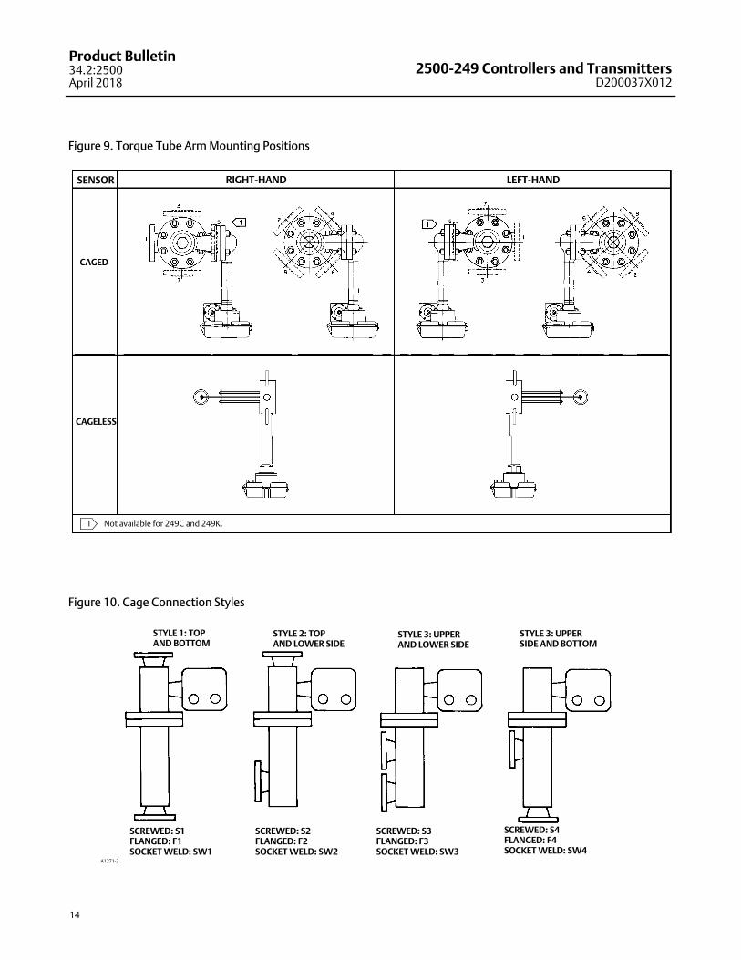
Figure 9. Torque Tube Arm Mounting Positions
RIGHT-HAND LEFT-HANDSENSOR
CAGED
CAGELESS
�1� Not available for 249C and 249K.
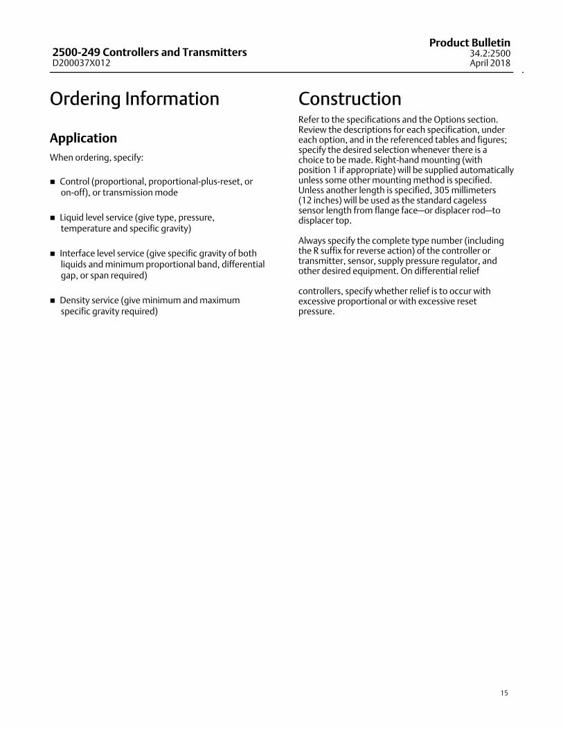
Figure 10. Cage Connection Styles
A1271‐3
SCREWED: S1FLANGED: F1SOCKET WELD: SW1
SCREWED: S2FLANGED: F2SOCKET WELD: SW2
SCREWED: S3FLANGED: F3SOCKET WELD: SW3
SCREWED: S4FLANGED: F4SOCKET WELD: SW4
STYLE 1: TOP AND BOTTOM
STYLE 2: TOP AND LOWER SIDE
STYLE 3: UPPERAND LOWER SIDE
STYLE 3: UPPERSIDE AND BOTTOM
2500-249 Controllers and TransmittersD200037X012
Product Bulletin34.2:2500April 2018
15
Ordering Information
Application
When ordering, specify:
� Control (proportional, proportional‐plus‐reset, oron‐off), or transmission mode
� Liquid level service (give type, pressure,temperature and specific gravity)
� Interface level service (give specific gravity of bothliquids and minimum proportional band, differentialgap, or span required)
� Density service (give minimum and maximumspecific gravity required)
ConstructionRefer to the specifications and the Options section.Review the descriptions for each specification, undereach option, and in the referenced tables and figures;specify the desired selection whenever there is achoice to be made. Right‐hand mounting (withposition 1 if appropriate) will be supplied automaticallyunless some other mounting method is specified.Unless another length is specified, 305 millimeters(12 inches) will be used as the standard cagelesssensor length from flange face—or displacer rod—todisplacer top.
Always specify the complete type number (includingthe R suffix for reverse action) of the controller ortransmitter, sensor, supply pressure regulator, andother desired equipment. On differential relief
controllers, specify whether relief is to occur withexcessive proportional or with excessive resetpressure.

2500-249 Controllers and TransmittersD200037X012
Product Bulletin34.2:2500April 2018
16
Emerson Automation SolutionsMarshalltown, Iowa 50158 USASorocaba, 18087 BrazilCernay, 68700 FranceDubai, United Arab EmiratesSingapore 128461 Singapore
www.Fisher.com
The contents of this publication are presented for informational purposes only, and while every effort has been made to ensure their accuracy, they are notto be construed as warranties or guarantees, express or implied, regarding the products or services described herein or their use or applicability. All sales aregoverned by our terms and conditions, which are available upon request. We reserve the right to modify or improve the designs or specifications of suchproducts at any time without notice.
� 1990, 2018 Fisher Controls International LLC. All rights reserved.
Fisher is a mark owned by one of the companies in the Emerson Automation Solutions business unit of Emerson Electric Co. Emerson Automation Solutions,Emerson, and the Emerson logo are trademarks and service marks of Emerson Electric Co. All other marks are the property of their respective owners.
Neither Emerson, Emerson Automation Solutions, nor any of their affiliated entities assumes responsibility for the selection, use or maintenanceof any product. Responsibility for proper selection, use, and maintenance of any product remains solely with the purchaser and end user.