This is the pre-peer revied version of a paper published by Advanced Functional
Materials (http://onlinelibrary.wiley.com/journal/10.1002/(ISSN)1616-3028) which can
be obtained under: http://onlinelibrary.wiley.com/doi/10.1002/adfm.201100063/abstract
DOI: 10.1002/adfm.201100063
Field-tuneable diamagnetism in ferromagnetic-superconducting
core-shell structures.
By André Müller*, and Sara E. C. Dale, and Miles A. Engbarth, and Simon J. Bending*, and
Laurence M. Peter, and Andreas Knittel, and Hans Fangohr.
[*] Corresponding Authors
A. Müller, Dr. S. E.C. Dale, Dr. M. A. Engbarth, Prof. S. J. Bending
Department of Physics
Claverton Down, Bath BA2 7AY, UK
E-mail: [email protected], [email protected]
Prof. L. M. Peter
Department of Chemistry
Claverton Down, Bath BA2 7AY, UK
A. Knittel, Dr. H. Fangohr
School of Engineering Sciences
University of Southampton, Southampton SO17 1BJ, UK
Keywords: Hybrid materials, Core/Shell Nanoparticles, Superconductors, Magnetic Materials,
Data storage, Sensors
Three dimensional ferromagnet-superconductor core-shell structures are realized by
electrocrystallisation and their magnetic properties investigated. We observe fully re-entrant
core superconductivity in increasing fields that survives well above the bulk critical field due
to compensation effects. The net measured magnetization of optimized structures could be
switched from absolute paramagnetic to diamagnetic by tuning the external magnetic field.
Micromagnetic simulations of our structures are in good qualitative agreement with our
results.
1. Introduction
The ability to controllably reverse the sign of magnetization of a material would lead to many
novel applications in the areas of magnetic guidance and magnetic devices. The ultimate
example of this would be switching a perfectly diamagnetic superconducting sample into a
ferromagnetic one. Superconductivity and ferromagnetism are, however, generally mutually
incompatible phenomena since the exchange interaction that leads to spin alignment in
ferromagnets destroys the usual superconducting ground state composed of electron pairs with
opposite spins. Superconductivity can, however, sometimes be induced in ferromagnetic
metals by a large applied magnetic field that opposes and compensates the exchange field; the
so-called Jaccarino-Peter (J-P) effect[1]
which is accompanied by the reversal of the sign of
magnetization. The apparent conflict between the two phenomena can also be overcome in
inhomogeneous materials when the carriers responsible for the different ordered states are
separated in space. This principle has guided the development of artificial ferromagnet-
superconductor hybrid (FSH) structures that have been intensively investigated in recent
years.[2 - 5]
The combination of superconductors with magnetic materials leads to many interesting
potential applications. If the stray fields of the ferromagnetic component are relatively weak
they can partially compensate an externally applied magnetic field, or a field generated by a
superconducting current, leading to an increase in the overall critical field(current) at which
the superconducting state is destroyed. Alternatively, if the stray field of the ferromagnet
exceeds the critical field in the adjacent superconductor, superconductivity can be switched on
again by applying an opposing external field to compensate it. Such field-induced
superconductivity can be thought of as kind of inhomogeneous analogue of the J-P effect and
was recently demonstrated in thin Pb films with arrays of Co/Pd nanomagnets patterned on
the surface.[6]
Such FSH could find important applications in novel superconducting magnetic
memory devices,[7 - 9]
or might be incorporated into superheated tin granules for high energy

particle detection at much higher magnetic fields.[10]
In addition FSH composites could, in
principle, be designed in such a way that their net magnetic response changes from para(ferro-
)magnetic to diamagnetic over a distinct range of externally applied fields (though this has not
yet been demonstrated in lithographic samples to the best of our knowledge). The
corresponding change in sign of the magnetic force exerted on the FSH could be exploited in
advanced magnetic guidance devices.
To date, experimental and theoretical studies of FSH have focused primarily on one
dimensional nanowires/nanorods,[11]
two dimensional layered structures[12 - 16]
or arrays of
ferromagnetic nanodots patterned on top of thin superconducting films.[6,17 - 19]
The
linear/planar geometry of the ferromagnetic component in such structures typically leads to
strong demagnetization effects and limits the scope for controlling the magnetic environment
of the adjacent superconductor. Recent developments in electrocrystallisation have, however,
made it possible to realize fully three dimensional core-shell structures combining various
superconducting and ferromagnetic materials.[20 - 22]
In stark contrast to earlier work, where
FSHs were often prepared using lithographic methods, the electrochemical approach allows
one to prepare highly faceted three dimensional single crystalline superconducting ’cores’ that
are completely or mostly covered by a polycrystalline ferromagnetic ’shell’. In addition, our
preparation method is much more suitable for practical applications, being faster and cheaper
than lithographic approaches and readily scalable to large sample numbers.
Here we report Hall magnetometry on individual core-shell structures of this type where the
core is a highly faceted microcrystal of superconducting lead (Pb) or tin (Sn) and the shell is
composed of a ferromagnetic Ni film. We show that the magnetic properties of these FSH can
be controlled by varying their size and shape as well as the thickness of the ferromagnetic
shell. Optimized structures show fully re-entrant superconductivity at high magnetic fields
whose measured magnetization completely reverses from para(ferro-)magnetic to diamagnetic
over a fairly narrow range of applied fields.

Our results not only demonstrate the advantages of using electrochemistry to prepare three
dimensional FSHs, but also illustrate their fascinating new properties.
2. Results
Figure 1. Plots of M/Msat versus Hext for three different Pb-Ni triangular-shaped samples (a - c) and a
Sn-Ni square cuboid-shaped sample (d). Curves have been offset for clarity. For each
measured FSH one curve for T = 4.2 K < TcPb
(T = 2 K < TcSn
for the Sn-Ni crystal in d) is
shown for positive (solid, red) and negative (dotted, purple) field sweeps, as well as a similar
curve for T > Tccore
(solid black and dotted dark grey respectively). For the sample in plot (c),
an additional curve is shown at T = 2 K (solid, blue and dotted, turquoise) illustrating the
absolute change from measured para(ferro-)magnetic to diamagnetic behavior at intermediate
external fields.
Figure 1 shows 'local' magnetization data measured for four different FSH crystals. The three
top curves (a-c) show data for Pb-Ni triangular platelet-shaped crystals, while the bottom

curve (d) shows data for a Sn-Ni cuboid-shaped crystal. For each crystal the pure
ferromagnetic signal from the Ni shell measured at a temperature above the critical
temperature of the core is shown in dark grey and black for up and down field sweeps
respectively. The red (down sweep) and magenta (up sweep) curves show the local
magnetization for T = 4.2 K < TcPb
= 7.18 K for the Pb-Ni samples and for T = 2 K < TcSn
=
3.72 K for the Sn-Ni sample. Clearly the measured magnetization changes dramatically when
the core becomes superconducting. The critical field of bulk lead (HcPb
(4.2 K)= 527 G) is
indicated by vertical dotted lines for comparison and we see that superconductivity survives
well above this field in all three Pb/Ni core-shells. In particular, at positive values of Hext and
decreasing fields, or vice versa, a pronounced diamagnetic superconducting "dome" is visible,
which starts to form at fields far in excess of the critical field of bulk lead. In this regime the
side walls of the ferromagnetic shell are almost fully saturated with magnetization MFM (c.f.,
figure 5b) and generate a stray field HFM that opposes the external field, Hext. Hence the local
field at the core, which is the vector sum of the stray and applied fields, is lowered to below
HcPb
and superconductivity survives. This compensation effect is clearly visible for all Pb-Ni
core-shell samples measured (figure 1(a-c)), being strongest in the structure with the longest
side length of 5.7µm and weakest in that with the shortest side length of 3.3 µm. Additional
curves are shown for the largest Pb-Ni crystal at T = 2 K << TcPb
(figure 1c, turquoise and
blue lines for up and down sweeps respectively). These plots show that at this very low
temperature, when the critical field of the core is the highest, the measured magnetization can
actually be tuned from para(ferro-)magnetic at high and low fields to absolute diamagnetic
near the peak of the superconducting dome.
We also observe superconductivity well above the bulk critical field of the tin core (HcSn
(2 K)
= 214 G) in the Sn-Ni FSH shown in figure 1d, but the diamagnetic 'dome' is considerably
less pronounced than in Pb-Ni samples. This is a consequence of the much lower critical field
of Sn; the stray fields of the Ni shell only become comparable in magnitude to HcSn
once it

has evolved into a significantly demagnetized state. Hence the range of applied fields for
which |Hext + HFM | < Hc is rather narrow and governed more by magnetization reversal of the
shell than field compensation effects. Hence, we focus on the properties of Pb-Ni core-shell
samples in the rest of this paper.
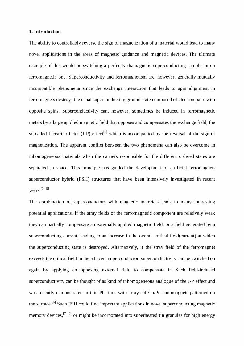
Figure 2. Plots of the magnetization measured at temperatures T<Tc
Pb with the ferromagnetic
contribution at T>TcPb
subtracted. Four different characteristic regions, I - IV, are observed
(see text). The inset shows an expanded view of the diamagnetic 'noise' seen in region III.
In order to highlight changes in the magnetization which occur when the core becomes
superconducting, figure 2 shows 'difference' traces, ΔM, of the largest Pb-Ni triangle sample
shown in figure 1 where the measured magnetization data for T = 7.5 K > TcPb
have been
subtracted from that at various temperatures, T < TcPb
. Four distinct regimes can be identified
in these data. For positive applied field sweeps from large negative values (Hext < -Hsat)
superconductivity first nucleates at the left hand edge of the region labeled I. In this regime
the magnetization of the Ni shell is almost fully saturated with moments pointing downwards
(c.f., the corresponding dark grey curve in figure 1 for T > TcPb
) and stray fields from the side
walls of the Ni shell oppose the direction of the applied field. Superconductivity will first
begin to nucleate when | Hext + HFM | < Hc(T) anywhere in the Pb core. The nucleated
superconducting regions will then continue to grow in size as the applied field is increased
and this inequality becomes satisfied in an increasingly larger volume of the core, reaching a
peak roughly when |Hext| ≈ |HFM|. For yet more positive applied fields the superconducting
volume starts to shrink again because the applied field is too small to fully compensate the Ni
stray fields and collapses completely when |Hext + HFM| > Hc(T) everywhere in the Pb core.
At the right hand boundary of region I the magnetization of the Ni shell starts to reverse and
the behavior of the core-shell sample becomes much more complex (region II in figure 2).
Reversal results in weaker stray fields, HFM, in the superconducting core and
superconductivity should be restored in some regions of the sample. The surprising zero
crossing of ΔM as a function of Hext in region II at low temperatures indicates a more
paramagnetic net response for T < Tc. This rather counter-intuitive result must be due to
screening of the stray fields of the partially reversed Ni shell by puddles of superconductivity
in the core that actually throws out more flux towards the Hall magnetometer.
The applied field region where the normal state magnetization reversal is steepest is
dominated by an irregular series of sharp Barkhausen 'steps'[23]
arising from abrupt jumps in
the location of domain walls or magnetic vortices between strong pinning sites in the Ni shell.
This is labeled region III in figure 2, and the ΔM data in this regime have been expanded in an
inset. We see that each jump in magnetization is accompanied by a correlated jump in the
diamagnetic response of the superconducting core. Since local changes in the magnetization
structure can either increase or decrease the local stray fields, they can either promote or
destroy superconductivity resulting in the non-monotonic diamagnetic "noise" clearly visible
in the inset of figure 2.
A further increase in applied field (region IV in figure 2) yields another diamagnetic
superconducting 'dome', similar to that seen in region I but of opposite sign. This indicates
that the magnetization of the Ni shell is now almost fully reversed and saturated along the
direction of the applied field, and the same compensation mechanisms come in to play as
were discussed for region I. As expected, reversing the sweep direction from Hext > Hmax
results in the same evolution of diamagnetic signal with regions I-IV reflected about the
magnetization axis (y-axis).
In order to gain insight into the size and shape of the superconducting regions in the core at
various positions on the M-H curve of the Ni shell, we have performed micromagnetic
simulations of our samples using the finite-element solver NMAG. In our micromagnetic
model we only consider the magnetic properties of the shell. We set the constant for the
exchange coupling equal to 7.2 ∙ 10-7
erg cm-1
, and the saturation magnetization Msat equal to
6409 Oe.[24]
The inclusion of the magnetocrystalline anisotropy of Ni is non-trivial due to the
polycrystalline character of the Nickel shell and has not been considered here. NMAG
discretizes the micromagnetic equations on an unstructured (tetrahedral) mesh. Sufficient
accuracy of the method can be ensured by keeping the tetrahedral edge length smaller than the
exchange length, lexch. We define a separate, relatively coarse mesh within the core region
(with a tetrahedral edge length of about 20 nm), since we want to resolve the shell's stray field
there. After having relaxed the magnetization of the shell, we can thus probe the stray field at
the nodes of the core mesh. NMAG computes the magnetostatic interaction using a hybrid
finite element/boundary element method (FEM/BEM), which involves the assembly and
storage of a boundary element matrix. We have approximated this by a hierarchical matrix,
which, for the presented simulation, reduces its memory footprint from about 94 GB to 1.3
GB. Since state-of-the-art micromagnetic simulations do not yet allow one to model our
actual sample sizes, simulation dimensions have been scaled down by a factor of about 10 to
make the problem tractable. We have also ignored the screening currents and associated fields
due to the superconducting regions of the core since incorporating such effects would require
coupled solutions of the micromagnetic and Ginzburg-Landau equations, something which
goes well beyond the scope of this work. Despite these approximations we believe our
simulations should give reliable qualitative results when the Ni shell is close to magnetic

saturation and will predict the onset fields for the nucleation of superconductivity with
reasonable accurately.
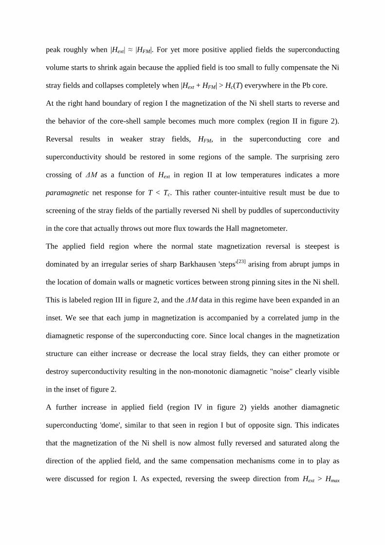
Figure 3. Micromagnetic simulations of a Pb-Ni triangular platelet-shaped core shell sample (see text).
(a) The superconducting volume fraction of the core as a function of applied magnetic field.
(b) 3D renderings of the superconducting volumes (dark red) in the core (where |Hext + HFM| <
HcPb
) at the applied fields indicated on (a). (c) 3D vector plot of the magnetization along the z-
axis Mz / Msat of the shell at the 'freezing' field of Hext = 1000 Oe.
Figure 3 illustrates the results of simulations for a 25 nm thick Ni shell deposited on the top
and sides of a triangular platelet-shaped core of thickness 220 nm and side-length 570 nm (c.f.,
also magnetization data in figure 1c). The plot in figure 3a shows the calculated
superconducting fraction of the core for a range of external magnetic fields (negative sweep
direction from Hext > Hmax), where these regions are defined by the inequality | Hext + HFM | <
Hc. Bulk Pb is a type I superconductor with susceptibility χ = -1 in the Meissner state (H < Hc)
and we assume that the diamagnetic signal from the core is directly proportional to this
superconducting volume fraction. Since domain wall pinning is not present in our
micromagnetic model, magnetic reversal starts earlier in simulations than is observed
experimentally. To account for this we have 'frozen' the magnetic domain structure at Hext =
1000 Oe and assumed that it remains unchanged as the field is swept to lower values in figure
3a. We note that our simulations are not at all sensitive to the choice of domain freezing field
for values larger than 800 Oe. Under these assumptions we see that the estimated
superconducting fraction is in good qualitative agreement with the diamagnetic 'dome' seen in
this regime in figure 1. Figure 3b shows 3D plots of the superconducting volume at the
various indicated points on figure 3a. We see clearly how superconductivity first nucleates in
a ring around the base edges and in three distinct points on the top surface of the core. These
regions then expand and join up through the centre until they fill the entire core at the peak of
the diamagnetic 'dome'. As the applied field is decreased beyond this point superconductivity
starts to be destroyed again from the edges inwards. Figure 3c shows a 3D vector plot of the
magnetization of the shell at Hext = 1000 Oe. Note the presence of a magnetic vortex in the
centre of the top surface of the Ni shell which is clearly correlated with the nucleation and
destruction of superconductivity in the Pb core in figure 3b. This observation leads us to
speculate that the presence and motion of such vortices is important in determining the
detailed evolution of superconductivity in the core.
3. Discussion
The onset of superconductivity in a homogeneous bulk sample is uniquely controlled by the
external parameters magnetic field, Hext, and temperature, T. In contrast, superconductivity in
our FSH core-shell structures also has a history-dependence via the magnetization structure of
the ferromagnetic shell. This adds a rich new control parameter for the onset of
superconductivity and diamagnetism. The criterion for the nucleation of superconductivity in
the core is that the ferromagnetic stray fields and applied field must compensate one another
so that the vector sum lies below the temperature-dependent critical field, Hc, locally. Re-
entrant or field-induced superconductivity have been demonstrated before in essentially
planar structures. Our 3D core-shell geometry gives much more control over the local
magnetic environment and has allowed us to demonstrate a complete field-driven reversal in
the absolute measured magnetic response of the composite structure from para(ferro-

)magnetic to diamagnetic. In addition, our ability to monitor the total magnetization of the
FSH as the Ni shell is being reversed allows us to directly correlate changes in the
magnetization state of the shell with the appearance/disappearance of diamagnetism. A rather
compelling example of this is the observation of non-monotonic diamagnetic 'noise' in regime
III of figure 2 which is intimately correlated with Barkhausen events in the ferromagnetic
shell. Small jumps in the positions of domain walls in the Ni shell lead to local
increases/decreases in stray fields and local nucleation/destruction of superconductivity.
Hence, this complex diamagnetic signal contains detailed information about the
micromagnetic structure of the shell and can be used to inform/test more detailed models of it.
Since our structures are grown using electrochemical crystallization it is not possible to
include an insulating buffer layer between superconductor and ferromagnet. Hence the
superconductor is in direct intimate contact with the ferromagnetic shell and one would expect
the suppression of superconductivity near this interface via the proximity effect. However, the
proximity effect is only expected to extend about a coherence length (ξ(0) ≈ 80 nm for Pb)
into the surface of the superconducting shell, which is nearly two orders of magnitude smaller
than the typical side length of one of our Pb triangles. Hence the effect would not be expected
to have any observable consequences.
The micromagnetic simulations shown in figure 3 reproduce the onset field of the diamagnetic
superconducting 'dome' of figure 2 quite well, but its broad inverted U-shaped profile is
somewhat different from the more pointed shape observed experimentally. This is a
consequence of the simulation of domain wall pinning by freezing the magnetization state of
the Ni shell at Hext = 1000 Oe while some magnetic relaxation is, in fact, taking place in our
measurements in this region. Our simulations also ignore screening currents and fields arising
in the diamagnetic core which should be added to the ferromagnetic and external field
contributions in a truly self-consistent way in order to calculate the superconducting volumes.

While this could be achieved in the future by solving coupled micromagnetic and Ginzburg-
Landau equations, it is currently beyond the scope of this work.
Finally we note that several recent theoretical and experimental works [14,25,26]
have studied
modifications in the magnetization reversal of a ferromagnet in close contact with a
superconductor, via changes in the magnetostatic energy arising from screening effects. We
have carefully analyzed our data for any sign of this behavior, particularly in regime III of
figure 2 where we see the irregular series of abrupt Barkhausen jumps. In practice the field
positions of these jumps are not completely reproducible from cycle to cycle, even at T > Tc.
Hence it is not possible to identify any systematic shift in jump positions at T < Tc when the
core becomes superconducting. However, we cannot rule out that such effects are also at play
in our core-shell structures.
3. Conclusion
In conclusion, we have demonstrated that it is possible to prepare high quality 3D FSH core-
shell structures by electrocrystallization on Boron-doped diamond substrates. We demonstrate
that superconductivity survives in these samples up to magnetic fields well in excess of the
bulk critical field of the superconducting core due to field compensation effects. For the case
of Pb-Ni core-shell structures we observe a diamagnetic superconducting 'dome' as a function
of applied magnetic field with a maximum at the point where Hext ≈ -HFM, where HFM is the
stray field of the saturation magnetized Ni shell at the centre of the Pb core. For the largest
Pb-Ni triangles we are actually able to switch the net measured magnetic behavior from
absolute para(ferro-)magnetic to diamagnetic by tuning the external magnetic field.
Micromagnetic simulations have been used to model the stray field distribution of the
ferromagnetic shell and, by mapping the regions of the core where |Hext + HFM| < Hc, predict
dome-shaped superconducting volumes as a function of applied magnetic field which are in
good qualitative agreement with experiment. Simulations also give valuable insights into the

size and shape of the superconducting volumes that nucleate in the core under different
conditions, and suggest that the motion of magnetic vortices may be important in determining
the detailed evolution of superconductivity. We also observe non-monotonic diamagnetic
'noise' in our measurements which is directly correlated with Barkhausen jumps in the shell
magnetization and arises from increases or decreases in the local stray fields that either
promote or destroy superconductivity.
Hybrid core-shell structures of the type described here could find important applications in
advanced magnetic guidance systems or superconducting memory devices as well as for
particle detection at very high magnetic fields.
4. Experimental
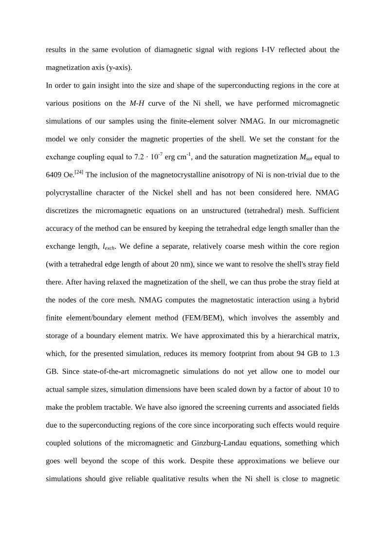
Figure 4. a) Schematic diagram of the electrochemical cell used to grow and plate the core-shell
samples composed of a counter electrode (CE), a reference electrode (RE) and a working
electrode (WE). b) and c) 3D Atomic force microscope images of a triangular Pb-Ni platelet
and a Sn-Ni cuboid respectively. d) Sketch, with dimensions, of the largest Pb-Ni triangular
prism investigated here. e) and f): FIB milled cross-sections of a Pb-Ni and a Sn-Ni sample
respectively. The side length of the inset expanded images is 500 nm.

Our experiments have been performed with electrochemically grown tin and lead single
crystal cores, which were then electroplated with a nickel shell layer of controllable thickness.
This route has many advantages over more conventional lithographic approaches. Not only
does it allow us to realize three dimensional core-shell structures, it is also fast and cheap..
Although we are only interested here in individual FSH crystals, each electrodeposition
results in a very large number of almost identical structures with very similar properties, ideal
for scaling up for future applications.
Superconducting lead microcrystals were prepared from lead(II)nitrate (Pb(NO3)2; 5-25 mM)
and boric acid (H3BO3; 100-250 mM) solutions made with Milli-Q water (ρ > 18.2 MΩ cm-1
).
A boron doped diamond (BDD) was used as the working electrode and the crystals were
grown for 60 s at an overpotential of -800 mV measured versus a Ag/AgCl reference
electrode. Tin cores were deposited from a tin(II)tetrafluoroborate (25 mM) and fluoroboric
acid (100 mM) solution made with Milli-Q water. They were also grown on a BDD electrode
at -780 mV for 30 s. A Watts bath (100 mM Ni(SO3Ni2)2 + 15 mM NiCl2 + 65 mM H3BO3)
was used to deposit the nickel shell onto all the crystals. Typically the cores were plated for
10 s at an overpotential of -1.2 V versus a Ag/AgCl reference electrode. The electrodeposition
setup is sketched in figure 4a, while figure 4b and c show two atomic force microscope
images of a typical triangular-shaped Pb/Ni sample and a square cuboid-shaped Sn-Ni sample
respectively. Figure 4d illustrates the geometry of core and shell in the case of the Pb-Ni
sample of figure 4b. The net charge flow during Ni deposition was used to estimate the
thickness of the shell (≈ 100 – 300 nm) subject to assumptions about the density and mean
surface area of the single crystal cores. In practice very similar conditions were used to grow
all 'shells' and the Ni thicknesses are not expected to vary much from structure to structure.
Simulations of the saturation magnetization, Msat, measured at the Hall probe under the crystal
yield a shell thickness of ≈ 200 – 300 nm, which is slightly larger but still in good agreement
with the estimation from electrochemical parameters and the micrographs in figure 4e and f.
Focused ion beam (FIB) sectioning was used to investigate the internal structure of core-shell
structures grown in this way. A thin Pt layer was first FIB-deposited on the region of interest
in order to protect it while it was being milled. The FIB was then used to slice a cross-section
through the core-shell and polish it prior to imaging the exposed surface. The resulting images
are shown in figure 4e and f for a triangular Pb-Ni structure and a cuboid Sn-Ni structure
respectively. The sharp interface between the tin or lead core and the nickel shell is clearly
visible (see insets of figure 4e and f) and there is no evidence at all of alloying or
interdiffusion. These images also confirm estimates of the Ni shell thicknesses to be of the
order of ≈ 100 – 300 nm made on the basis of the electrodeposition parameters.
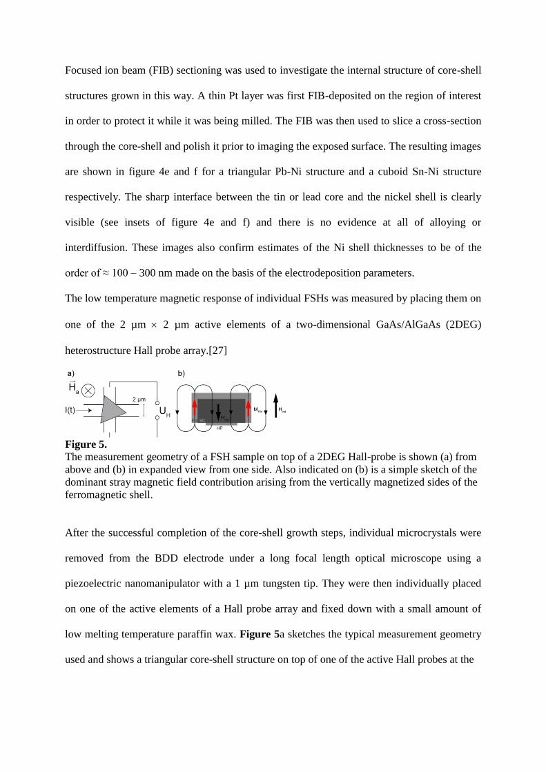
The low temperature magnetic response of individual FSHs was measured by placing them on
one of the 2 µm 2 µm active elements of a two-dimensional GaAs/AlGaAs (2DEG)
heterostructure Hall probe array.[27]
Figure 5. The measurement geometry of a FSH sample on top of a 2DEG Hall-probe is shown (a) from
above and (b) in expanded view from one side. Also indicated on (b) is a simple sketch of the
dominant stray magnetic field contribution arising from the vertically magnetized sides of the
ferromagnetic shell.
After the successful completion of the core-shell growth steps, individual microcrystals were
removed from the BDD electrode under a long focal length optical microscope using a
piezoelectric nanomanipulator with a 1 µm tungsten tip. They were then individually placed
on one of the active elements of a Hall probe array and fixed down with a small amount of
low melting temperature paraffin wax. Figure 5a sketches the typical measurement geometry
used and shows a triangular core-shell structure on top of one of the active Hall probes at the

intersection of two 2 µm wide wires. Figure 5b shows a side view of the same structure where
the two-dimensional electron gas forming the Hall effect sensor lies about 80 nm below the
bottom of the mounted core-shell structure. Also shown on this figure is a sketch of the
expected stray magnetic field lines from the ferromagnetic shell after saturation magnetization
in the upwards direction shown (parallel to Hext). Note that the dominant fields in the core
arise from moments in the vertical sidewalls of the Ni shell and point in the opposite direction
to the externally applied field. The Hall probes were driven with a 20 µA 314 Hz ac current
and the generated Hall voltage was detected using two digital lock-in amplifiers, one of which
was used to simultaneously record a reference signal from an 'empty' Hall probe. The two
measured Hall voltages were numerically subtracted to obtain a quantity directly proportional
to the 'local' magnetization of the sample. The Hall array was mounted on the end of a
temperature-controlled sample holder which was inserted into a stainless steel tube containing
helium exchange gas, which was in turn immersed in a liquid helium bath. The pressure in the
helium bath could be lowered with a rotary pump allowing temperatures down to about T ≈ 2
K to be reached. An external magnetic field was applied from a commercial superconducting
solenoid attached to the bottom of the sample tube.
Magnetization loops were captured by sweeping the applied field at constant temperature
from Hmax << -Hsat to Hmax >> Hsat and vice versa, where Hmax is the maximum applied field
and Hsat is the saturation field of the ferromagnetic FSH shell. Superconductivity was fully
suppressed in all structures at all temperatures at Hmax. Scans were repeated at various
temperatures up to and above the critical temperature (Tc) of the core material. All sweeps at
different temperatures were performed using the same values for Hmax, scan rate and point
density to enable an accurate comparison between the scans. This, and the fact that
magnetization reversal in the ferromagnetic shell showed no visible temperature dependence
for T < 10 K, allows us to subtract the data for T > Tc from the data for T < Tc in order to

highlight the contribution of the superconducting core to the magnetization of the entire FSH
sample.
Acknowledgements
We gratefully acknowledge the assistance of Dr P. Heard (IAC, University of Bristol) with
FIB sectioning and imaging of core-shell structures.
This work was supported by the Engineering and Physical Sciences Research Council
(EPSRC) in the UK under grants EP/E039944/1 and EP/E040063/1, the ESF-NES network
and the European Community's Seventh Framework Programme (FP7/2007-2013) under
grant agreement no. 233552 (DYNAMAG project).
1. Jaccarino, V. and Peter, M. Phys. Rev. Lett. 9(7), 290–292 Oct (1962).
2. Yang, Z., Lange, M., Volodin, A., Szymczak, R., and Moshchalkov, V. V. Nat Mater
3(11), 793–798 (2004).
3. Rusanov, A. Y., Hesselberth, M., Aarts, J., and Buzdin, A. I. Phys. Rev. Lett. 93(5),
057002 Jul (2004).
4. Lyuksyutov, I. F. and Pokrovsky, V. L. Advances in Physics 54(1), 67–136 (2005).
5. Aladyshkin, A. Y., Silhanek, A. V., Gillijns, W., and Moshchalkov, V.
V.Superconductor Science and Technology 22(5), 053001 (2009).
6. Lange, M., Bael, M. J. V., Bruynseraede, Y., and Moshchalkov, V. V. Phys. Rev. Lett.
90(19), 197006 May (2003).
7. Tagirov, L. R. Phys. Rev. Lett. 83(10), 2058–2061 Sep (1999).
8. Gu, J. Y., You, C.-Y., Jiang, J. S., Pearson, J., Bazaliy, Y. B., and Bader, S. D. Phys.
Rev. Lett. 89(26), 267001 Dec (2002).
9. Nemes, N. M., Visani, C., Leon, C., Garcia-Hernandez, M., Simon, F., Fehér, T., te
Velthuis, S. G. E., Hoffmann, A., and Santamaria, J. Applied Physics Letters 97(3), 032501
(2010).
10. Larrea, A., Morales, A., Waysand, G., and Bartolomé, J. Nuclear Instruments and
Methods in Physics Research Section A: Accelerators, Spectrometers, Detectors and
Associated Equipment 317(3), 541 – 544 (1992).
11. Lin, L. K., Chi, Y. S., Chen, T. M., Shyu, S. G., Huang, J. H., and Lee, S. F. Journal
of Applied Physics 105(7), 07D519 (2009).
12. Garif’yanov, N., Goryunov, Y., Mühge, T., Lazar, L., Khaliullin, G., Westerholt, K.,
Garifullin, I., and Zabel, H. The European Physical Journal B - Condensed Matter and
Complex Systems 1, 405–407 (1998). 10.1007/s100510050203.11
13. Bulaevskii, L. N. and Chudnovsky, E. M. Phys. Rev. B 63(1), 012502 Dec (2000).
14. Dubonos, S. V., Geim, A. K., Novoselov, K. S., and Grigorieva, I. V. Phys. Rev. B
65(22), 220513 Jun (2002).
15. Gillijns, W., Aladyshkin, A. Y., Silhanek, A. V., and Moshchalkov, V. V. Phys. Rev. B
76(6), 060503 Aug (2007).
16. Tamegai, T., Nakao, Y., Tsuchiya, Y., and Nakajima, Y. Physica C: Superconductivity
468(15-20), 1308 – 1312 (2008). Proceedings of the 20th International Symposium on
Superconductivity (ISS 2007), Proceedings of the 20th International Symposium on
Superconductivity (ISS 2007).
17. Miloševic, M. V., Berdiyorov, G. R., and Peeters, F. M. Phys. Rev. Lett. 95(14),
147004 Sep (2005).
18. Golubovic, D. S., Pogosov, W. V., Morelle, M., and Moshchalkov, V. V. EPL
(Europhysics Letters) 65(4), 546 (2004).
19. Lange, M., Van Bael, M. J., Silhanek, A. V., and Moshchalkov, V. V. Phys. Rev. B
72(5), 052507 Aug (2005).

20. Xiao, Z.-L., Han, C. Y., Kwok, W.-K., Wang, H.-H., Welp, U., Wang, J., and Crabtree,
G. W. Journal of the American Chemical Society 126(8), 2316–2317 (2004).
21. Müller, A., Dale, S. E. C., Engbarth, M. A., Bending, S. J., and Peter, L. M.
CrystEngComm 12(7), 2135–2138 (2010).
22. Dale, S. E. C., Müller, A., Engbarth, M. A., Bending, S. J., and Peter, L. M. in
preparation.
23. Barkhausen, H. Z. Phys. 20, 401 (1919).
24. O’Handley, R. C. Modern Magnetic Materials: Principles and Applications. John
Wiley & Sons, (2000).
25. Bergeret, F. S., Volkov, A. F., and Efetov, K. B. Phys. Rev. B 69(17), 174504 May
(2004).
26. Fritzsche, J., Kramer, R. B. G., and Moshchalkov, V. V. Phys. Rev. B 79(13), 132501
Apr (2009).
27. Geim, A. K., Dubonos, S. V., Lok, J. G. S., Grigorieva, I. V., Maan, J. C., Hansen, L.
T., and Lindelof, P. E. Applied Physics Letters 71(16), 2379– 2381 (1997).