1/38 Siemens AP 01 · 2018
Extractive continuous process gas analysisSeries 6ULTRAMAT 6
General information1
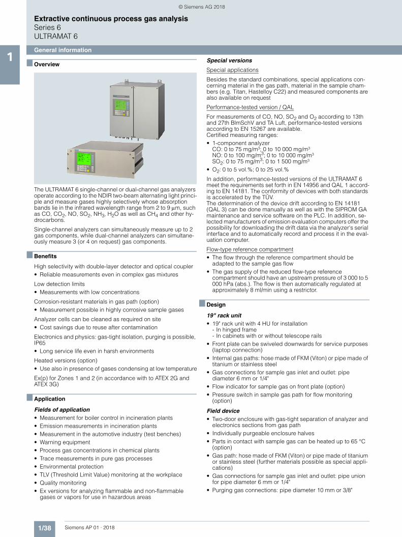
■ Overview
The ULTRAMAT 6 single-channel or dual-channel gas analyzers operate according to the NDIR two-beam alternating light princi-ple and measure gases highly selectively whose absorption bands lie in the infrared wavelength range from 2 to 9 m, such as CO, CO2, NO, SO2, NH3, H2O as well as CH4 and other hy-drocarbons.
Single-channel analyzers can simultaneously measure up to 2 gas components, while dual-channel analyzers can simultane-ously measure 3 (or 4 on request) gas components.
■ Benefits
High selectivity with double-layer detector and optical coupler• Reliable measurements even in complex gas mixtures
Low detection limits• Measurements with low concentrations
Corrosion-resistant materials in gas path (option)• Measurement possible in highly corrosive sample gases
Analyzer cells can be cleaned as required on site• Cost savings due to reuse after contamination
Electronics and physics: gas-tight isolation, purging is possible, IP65• Long service life even in harsh environments
Heated versions (option)• Use also in presence of gases condensing at low temperature
Ex(p) for Zones 1 and 2 (in accordance with to ATEX 2G and ATEX 3G)
■ Application
Fields of application• Measurement for boiler control in incineration plants• Emission measurements in incineration plants• Measurement in the automotive industry (test benches)• Warning equipment• Process gas concentrations in chemical plants• Trace measurements in pure gas processes• Environmental protection• TLV (Threshold Limit Value) monitoring at the workplace• Quality monitoring• Ex versions for analyzing flammable and non-flammable
gases or vapors for use in hazardous areas
Special versions
Special applications
Besides the standard combinations, special applications con-cerning material in the gas path, material in the sample cham-bers (e.g. Titan, Hastelloy C22) and measured components are also available on request
Performance-tested version / QAL
For measurements of CO, NO, SO2 and O2 according to 13th and 27th BlmSchV and TA Luft, performance-tested versions according to EN 15267 are available.Certified measuring ranges:• 1-component analyzer
CO: 0 to 75 mg/m³; 0 to 10 000 mg/m³NO: 0 to 100 mg/m3; 0 to 10 000 mg/m³SO2: 0 to 75 mg/m3; 0 to 1 500 mg/m³
• O2: 0 to 5 vol.%; 0 to 25 vol.%
In addition, performance-tested versions of the ULTRAMAT 6 meet the requirements set forth in EN 14956 and QAL 1 accord-ing to EN 14181. The conformity of devices with both standards is accelerated by the TÜV.The determination of the device drift according to EN 14181 (QAL 3) can be done manually as well as with the SIPROM GA maintenance and service software on the PLC. In addition, se-lected manufacturers of emission evaluation computers offer the possibility for downloading the drift data via the analyzer's serial interface and to automatically record and process it in the eval-uation computer.
Flow-type reference compartment• The flow through the reference compartment should be
adapted to the sample gas flow• The gas supply of the reduced flow-type reference
compartment should have an upstream pressure of 3 000 to 5 000 hPa (abs.). The flow is then automatically regulated at approximately 8 ml/min using a restrictor.
■ Design
19" rack unit• 19" rack unit with 4 HU for installation
- In hinged frame- In cabinets with or without telescope rails
• Front plate can be swiveled downwards for service purposes (laptop connection)
• Internal gas paths: hose made of FKM (Viton) or pipe made of titanium or stainless steel
• Gas connections for sample gas inlet and outlet: pipe diameter 6 mm or 1/4"
• Flow indicator for sample gas on front plate (option)• Pressure switch in sample gas path for flow monitoring
(option)
Field device• Two-door enclosure with gas-tight separation of analyzer and
electronics sections from gas path• Individually purgeable enclosure halves• Parts in contact with sample gas can be heated up to 65 °C
(option)• Gas path: hose made of FKM (Viton) or pipe made of titanium
or stainless steel (further materials possible as special appli-cations)
• Gas connections for sample gas inlet and outlet: pipe union for pipe diameter 6 mm or 1/4"
• Purging gas connections: pipe diameter 10 mm or 3/8"
© Siemens AG 2018

1/39Siemens AP 01 · 2018
Extractive continuous process gas analysisSeries 6
ULTRAMAT 6
General information1Display and control panel
• Large LCD panel for simultaneous display of:- Measured value (digital and analog displays)- Status bar- Measuring ranges
• Contrast of the LCD field adjustable via the menu• Washable membrane keyboard with five softkeys• Menu-driven operation for parameterization, test functions,
adjustment• Operator support in plain text• Graphic display of concentration trend; programmable time
intervals• Bilingual operating software:
German/English, English/Spanish, French/English, Spanish/English, Italian/English
Inputs and outputs• One analog output per medium (from 0, 2, 4 to 20 mA; NAMUR
configurable)• Two analog inputs freely configurable (e.g. correction of
cross-interferences or external pressure sensor)• Six digital inputs freely configurable (e.g. for measurement
range switchover, processing of external signals from sample preparation)
• Six relay outputs freely configurable e.g. for fault, mainte-nance request, limit alarm, external solenoid valves)
• Expansion by eight additional digital inputs and eight additional relay outputs e.g. for autocalibration with up to four calibration gases
Communication
RS 485 present in the basic unit (connection at the rear; for the rack unit also behind the front plate).
Options• AK interface for the automotive industry with extended
functions• RS 485/RS 232 converter• RS 485/Ethernet converter• RS 485/USB converter• Connection to networks via PROFIBUS DP/PA interface• SIPROM GA software as the service and maintenance tool
ULTRAMAT 6, membrane keyboard and graphic display
Status line for display of analyzer status(programmable)
LED backlit graphicdisplay and membrane keyboardwith noticeable click
Two code levelsaccording to NAMUR(maintenance andspecialist level)
MEAS key to return tomeasurement mode
Easy operation with menu controlusing five softkeys
Display of currentmeasuring ranges
ESC keyto abort inputs
INFO keyfor help in plain text
CLEAR key to delete inputs
Keyboard toenter values
Display ofconcentrations asnumbers and bargraphfor channel 1
ENTER key to accept input values
Display of start-of-scale and full-scale values
Display ofconcentrations asnumbers and bargraphfor channel 2 Status line for channel 2
to display the unitstatus (programmable)
© Siemens AG 2018
1/40 Siemens AP 01 · 2018
Extractive continuous process gas analysisSeries 6ULTRAMAT 6
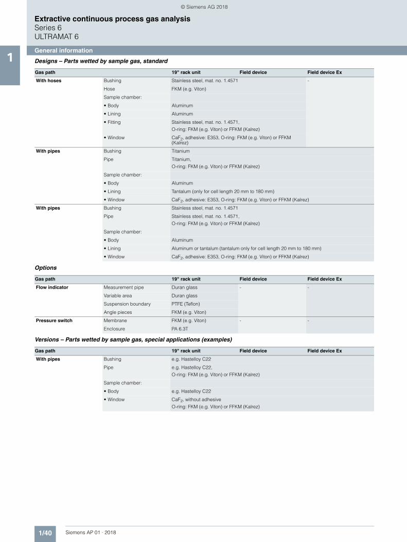
General information1 Designs – Parts wetted by sample gas, standard
Options
Versions – Parts wetted by sample gas, special applications (examples)
Gas path 19" rack unit Field device Field device Ex
With hoses Bushing Stainless steel, mat. no. 1.4571 -
Hose FKM (e.g. Viton)
Sample chamber:
• Body Aluminum
• Lining Aluminum
• Fitting Stainless steel, mat. no. 1.4571,
O-ring: FKM (e.g. Viton) or FFKM (Kalrez)
• Window CaF2, adhesive: E353, O-ring: FKM (e.g. Viton) or FFKM (Kalrez)
With pipes Bushing Titanium
Pipe Titanium,
O-ring: FKM (e.g. Viton) or FFKM (Kalrez)
Sample chamber:
• Body Aluminum
• Lining Tantalum (only for cell length 20 mm to 180 mm)
• Window CaF2, adhesive: E353, O-ring: FKM (e.g. Viton) or FFKM (Kalrez)
With pipes Bushing Stainless steel, mat. no. 1.4571
Pipe Stainless steel, mat. no. 1.4571,
O-ring: FKM (e.g. Viton) or FFKM (Kalrez)
Sample chamber:
• Body Aluminum
• Lining Aluminum or tantalum (tantalum only for cell length 20 mm to 180 mm)
• Window CaF2, adhesive: E353, O-ring: FKM (e.g. Viton) or FFKM (Kalrez)
Gas path 19" rack unit Field device Field device Ex
Flow indicator Measurement pipe Duran glass - -
Variable area Duran glass
Suspension boundary PTFE (Teflon)
Angle pieces FKM (e.g. Viton)
Pressure switch Membrane FKM (e.g. Viton) - -
Enclosure PA 6.3T
Gas path 19" rack unit Field device Field device Ex
With pipes Bushing e.g. Hastelloy C22
Pipe e.g. Hastelloy C22,
O-ring: FKM (e.g. Viton) or FFKM (Kalrez)
Sample chamber:
• Body e.g. Hastelloy C22
• Window CaF2, without adhesive
O-ring: FKM (e.g. Viton) or FFKM (Kalrez)
© Siemens AG 2018
1/41Siemens AP 01 · 2018
Extractive continuous process gas analysisSeries 6
ULTRAMAT 6
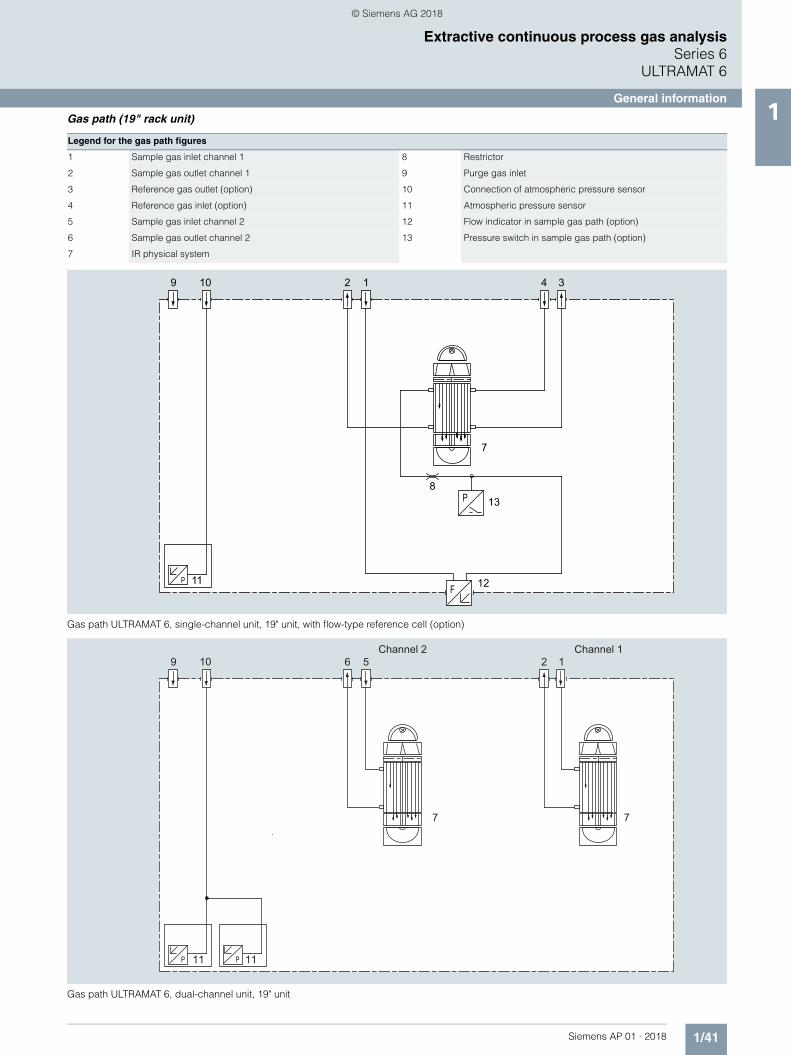
General information1Gas path (19" rack unit)
Gas path ULTRAMAT 6, single-channel unit, 19" unit, with flow-type reference cell (option)
Gas path ULTRAMAT 6, dual-channel unit, 19" unit
Legend for the gas path figures
1 Sample gas inlet channel 1 8 Restrictor
2 Sample gas outlet channel 1 9 Purge gas inlet
3 Reference gas outlet (option) 10 Connection of atmospheric pressure sensor
4 Reference gas inlet (option) 11 Atmospheric pressure sensor
5 Sample gas inlet channel 2 12 Flow indicator in sample gas path (option)
6 Sample gas outlet channel 2 13 Pressure switch in sample gas path (option)
7 IR physical system
PF
P
9 10 12 34
11
138
7
12
© Siemens AG 2018

1/42 Siemens AP 01 · 2018
Extractive continuous process gas analysisSeries 6ULTRAMAT 6
General information1 Gas path (field device)
Gas path ULTRAMAT 6, field unit, with flow-type reference cell (option)
Legend for the gas path figures
1 Sample gas inlet 7 Purging gas outlet (analyzer side)
2 Sample gas outlet 8 Purging gas inlet (analyzer side)
3 Reference gas inlet (option) 9 Connection of atmospheric pressure sensor
4 Reference gas outlet (option) 10 IR physical system
5 Purging gas inlet (electronics side) 11 Atmospheric pressure sensor
6 Purging gas outlet (electronics side)
© Siemens AG 2018

1/43Siemens AP 01 · 2018
Extractive continuous process gas analysisSeries 6
ULTRAMAT 6
General information1
■ Function
Principle of operation
The ULTRAMAT 6 gas analyzer operates according to the infra-red two-beam alternating light principle with double-layer detec-tor and optical coupler.
The measuring principle is based on the molecule-specific ab-sorption of bands of infrared radiation. The absorbed wave-lengths are characteristic to the individual gases, but may par-tially overlap. This results in cross-sensitivities which are reduced to a minimum in the ULTRAMAT 6 gas analyzers by the following measures:• Gas-filled filter cell (beam divider)• Double-layer detector with optical coupler• Optical filters if necessary
The figure shows the measuring principle. An IR source (1) which is heated to approx. 700 °C and which can be shifted to balance the system is divided by the beam divider (3) into two equal beams (sample and reference beams). The beam divider also acts as a filter cell.
The reference beam passes through a reference cell (8) filled with N2 (a non-infrared-active gas) and reaches the right-hand side of the detector (11) practically unattenuated. The sample beam passes through the sample chamber (7) through which the sample gas flows and reaches the left-hand side of the de-tector (10) attenuated to a lesser or greater extent depending on the concentration of the sample gas. The detector is filled with a defined concentration of the gas component to be measured.
The detector is designed as a double-layer detector. The center of the absorption band is preferentially absorbed in the upper detector layer, the edges of the band are absorbed to approxi-mately the same extent in the upper and lower layers. The upper and lower detector layers are connected together via the micro-flow sensor (12). This coupling means that the spectral sensitiv-ity has a very narrow band.
The optical coupler (13) lengthens the lower receiver cell layer optically. The infrared absorption in the second detector layer is varied by changing the slider position (14). It is thus possible to individually minimize the influence of interfering components.
A chopper (5) rotates between the beam divider and the sample chamber and interrupts the two beams alternately and periodi-cally. If absorption takes place in the sample chamber, a pulsat-ing flow is generated between the two detector levels which is converted by the microflow sensor (12) into an electric signal.
The microflow sensor consists of two nickel-plated grids heated to approximately 120 °C, which, along with two supplementary resistors, form a Wheatstone bridge. The pulsating flow together with the dense arrangement of the Ni grids causes a change in resistance. This leads to an offset in the bridge, which is depen-dent on the concentration of the sample gas.
Notes
The sample gases must be fed into the analyzers free of dust. Condensation should be prevented from occurring in the sample chambers. Therefore, the use of gas modified for the measuring task is necessary in most application cases.
As far as possible, the ambient air of the analyzer should not have a large concentration of the gas components to be measured.
Flow-type reference sides with reduced flow must not be oper-ated with flammable or toxic gases.
Flow-type reference sides with reduced flow and an O2 content > 70% may only be used together with Y02 (Clean for O2).
Channels with electronically suppressed zero point only differ from the standard version in the measuring range parameterization.
Physically suppressed zeros can be provided as a special ap-plication.
ULTRAMAT 6, principle of operation
1
2
3
5
6
7
4
8
9
10 11
13
14
12
1 IR source, adjustable 8 Reference cell 2 Optical filter 9 Sample gas outlet 3 Beam divider 10 Detector, meas. side 4 Eddy current drive 11 Detector, reference side 5 Chopper 12 Microflow sensor 6 Sample gas inlet 13 Optical coupler 7 Sample cell 14 Slider, adjustable
© Siemens AG 2018

1/44 Siemens AP 01 · 2018
Extractive continuous process gas analysisSeries 6ULTRAMAT 6
General information1 Essential characteristics
• Dimension of measured value freely selectable (e.g. vpm, mg/m3)
• Four freely-configurable measuring ranges per component • Measuring ranges with suppressed zero point possible• Measuring range identification• Galvanically isolated signal output 0/2/4 to 20 mA per
component• Automatic or manual measuring range switchover selectable;
remote switching is also possible• Differential measuring ranges with flow-type reference cell• Storage of measured values possible during adjustments• Time constants selectable within wide limits (static/dynamic
noise suppression); i.e. the response time of the analyzer or component can be matched to the respective measuring task
• Short response time• Low long-term drift• Measuring point switchover for up to 6 measuring points
(programmable)• Measuring point identification• Monitoring of sample gas flow (option)• Internal pressure sensor for correction of variations in
atmospheric pressure in the range 700 to 1 200 hPa absolute• External pressure sensor can be connected for correction of
variations in the process gas pressure in the range 700 to 1 500 hPa absolute (option)
• Two control levels with separate authorization codes to prevent unintentional and unauthorized inputs
• Automatic, configurable measuring range calibration• Simple handling using a numerical membrane keyboard and
operator prompting• Operation based on NAMUR recommendation• Customer-specific analyzer options such as:
- Customer acceptance- TAG labels- Clean for O2 service (specially cleaned gas path)
• Easy device replacement since electric connections can be simply disconnected from the device
• Sample chambers for use in presence of highly corrosive sample gases, e.g. tantalum layer or sample chamber made of Hastelloy C22 (special application)
Additional features, dual-channel version• Separate design of physical unit, electronics, inputs/outputs
and power supply for each channel• Display and operation via common LCD panel and keyboard• Measurement channels 1 and 2 can be converted to series
connection (linking of gas connections from channel 1 to channel 2 on rear)
© Siemens AG 2018

1/45Siemens AP 01 · 2018
Extractive continuous process gas analysisSeries 6
ULTRAMAT 6
19" rack unit1
■ Technical specifications
General information
Measuring ranges 4, internally and externally switchable; autoranging is also possible
Smallest possible measuring range Dependent on the application: e.g. CO: 0 … 10 vpm, CO2: 0 … 5 vpm
Largest possible measuring span Dependent on the application
Measuring range with suppressed zero point
Any zero point within 0 … 100 vol.% can be implemented; smallest possi-ble span 20%
Operating position Front wall, vertical
Conformity CE mark in accordance with EN 50081-1, EN 50082-2
Influence of interfering gases must be considered separately
Design, enclosure
Weight Approx. 15 kg (with one IR channel)
Approx. 21 kg (with two IR channels)
Degree of protection IP20 according to EN 60529
Electrical characteristics
EMC (electromagnetic compatibility) In accordance with standard require-ments of NAMUR NE21 (08/98)
Electrical safety According to EN 61010-1, overvoltage category III
Auxiliary power 100 … 120 V AC (nominal range of use 90 … 132 V), 48 … 63 Hz or
200 … 240 V AC (nominal range of use 180 … 264 V), 48 … 63 Hz
Power consumption 1-channel unit: Approx. 40 VA
2-channel unit: Approx. 70 VA
Fuse values• 100 ... 120 V 1 T/250 (7MB2121)
1.6 T/250 (7MB2123)• 200 ... 240 V 0.63 T/250 (7MB2121)
1 T/250 (7MB2123)
Gas inlet conditions
Permissible sample gas pressure• With hoses
- Without pressure switch 600 … 1 500 hPa (absolute)- With pressure switch 700 … 1 300 hPa (absolute)
• With pipes (without pressure switch)
600 … 1 500 hPa (absolute)
Sample gas flow 18 … 90 l/h (0.3 … 1.5 l/min)
Sample gas temperature Min. 0 ... max. 50 °C, but above the dew point
Sample gas humidity < 90% RH (relative humidity), or dependent on measuring task, non-condensing
Dynamic response
Warm-up period At room temperature < 30 min (the technical specification will be met after 2 hours)
Delayed display (T90-time) Dependent on length of analyzer chamber, sample gas line and configu-rable damping
Damping (electrical time constant) 0 … 100 s, configurable
Dead time (purging time of the gas path in the unit at 1 l/min)
Approximately 0.5 ... 5 s, depending on version
Time for device-internal signal pro-cessing
< 1 s
Pressure correction range
Pressure sensor• Internal 700 … 1 200 hPa absolute• External 700 … 1 500 hPa absolute
Measuring response Based on sample gas pressure 1 013 hPa absolute, 0.5 l/min sample gas flow and 25 °C ambient tempera-ture
Output signal fluctuation < ± 1% of the smallest possible mea-suring range according to rating plate
Zero point drift < ± 1% of the current measuring range/week
Measured-value drift < ± 1% of the current measuring range/week
Repeatability 1% of the current measuring range
Detection limit 1% of the smallest possible measuring range
Linearity error ± 0.5 % of the full-scale value
Influencing variables Based on sample gas pressure 1 013 hPa absolute, 0.5 l/min sample gas flow and 25 °C ambient tempera-ture
Ambient temperature < 1% of current measuring range/10 K (with constant receiver cell tempera-ture)
Sample gas pressure • With disabled pressure compensa-tion: < 0.15% of the span/1% change in atmospheric pressure
• With disabled pressure compensa-tion: < 1.5% of the span/1% change in atmospheric pressure
Sample gas flow Negligible
Auxiliary power < 0.1% of the current measuring range with rated voltage ± 10%
Environmental conditions Application-specific measuring influ-ences possible if ambient air contains measured components or cross inter-ference-sensitive gases
Electrical inputs and outputs
Analog output 0/2/4 ... 20 mA, isolated; load 750
Relay outputs 6, with changeover contacts, freely configurable, e.g. for measuring range identification; load: 24 V AC/DC/1 A, isolated, non-sparking
Analog inputs 2, dimensioned for 0/2/4 ... 20 mA for external pressure sensor and accom-panying gas influence correction (cor-rection of cross-interference)
Digital inputs 6, designed for 24 V, isolated, freely configurable, e.g. for measuring range switchover
Serial interface RS 485
Options AUTOCAL function each with 8 addi-tional digital inputs and relay outputs, also with PROFIBUS PA or PROFIBUS DP
Climatic conditions
Permissible ambient temperature -30 ... +70 °C during storage and transportation, 5 ... 45 °C during operation
Permissible humidity < 90% RH (relative humidity) as annual average, during storage and transpor-tation (dew point must not be under-shot)
© Siemens AG 2018
1/46 Siemens AP 01 · 2018
Extractive continuous process gas analysisSeries 6ULTRAMAT 6
19" rack unit1
Footnotes: see next page
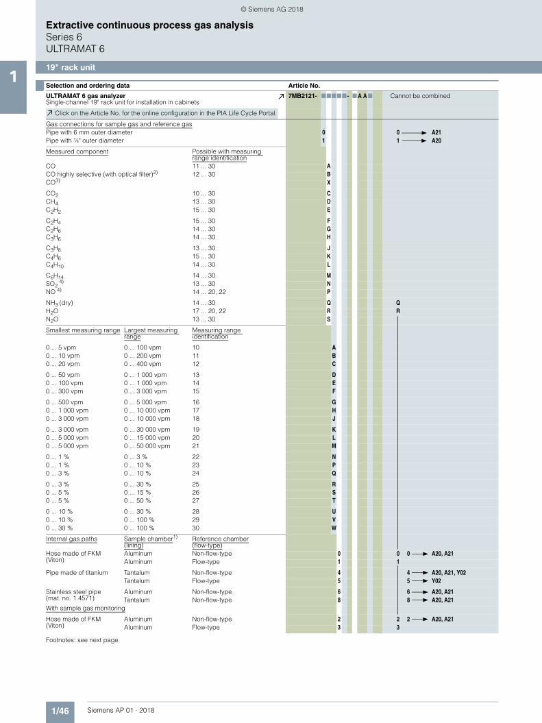
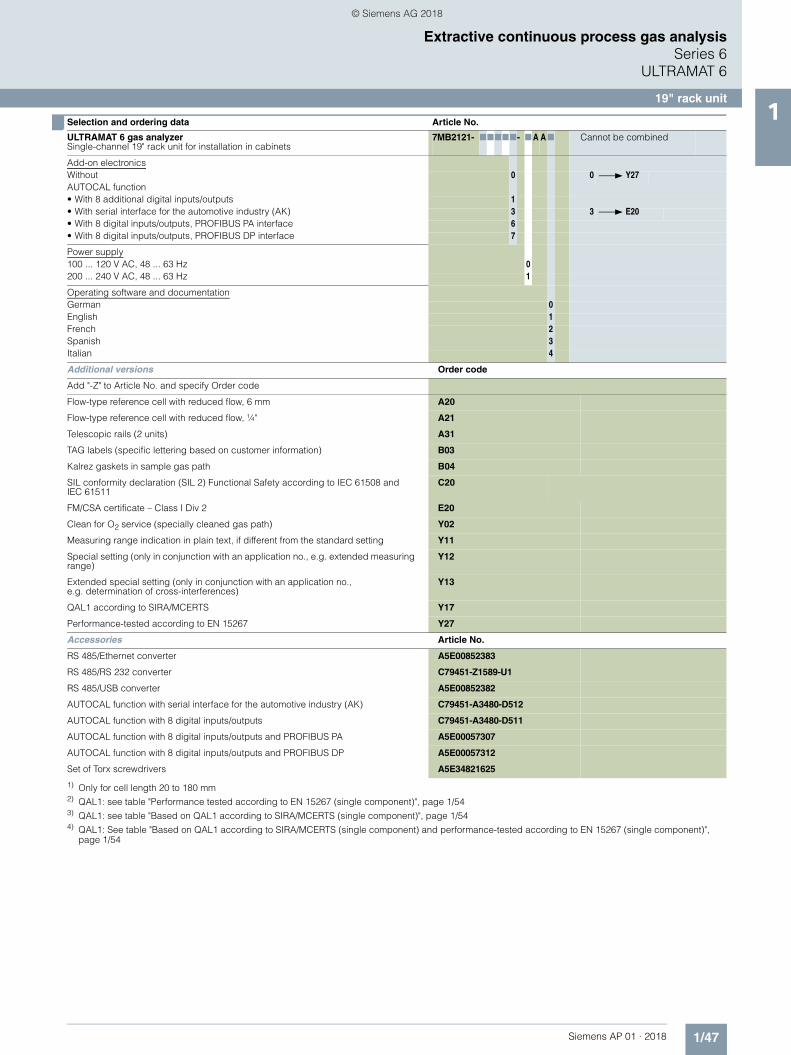
■ Selection and ordering data Article No.
ULTRAMAT 6 gas analyzerSingle-channel 19" rack unit for installation in cabinets
7MB2121- 77777- 7 A A7 Cannot be combined
Click on the Article No. for the online configuration in the PIA Life Cycle Portal.
Gas connections for sample gas and reference gasPipe with 6 mm outer diameter 0 0 A21Pipe with ¼" outer diameter 1 1 A20
Measured component Possible with measuring range identification
CO 11 ... 30 ACO highly selective (with optical filter)2) 12 ... 30 BCO3) X
CO2 10 ... 30 CCH4 13 ... 30 DC2H2 15 ... 30 E
C2H4 15 ... 30 FC2H6 14 ... 30 GC3H6 14 ... 30 H
C3H8 13 ... 30 JC4H6 15 ... 30 KC4H10 14 ... 30 L
C6H14 14 ... 30 MSO2
4) 13 ... 30 NNO
4) 14 ... 20, 22 P
NH3 (dry) 14 ... 30 Q QH2O 17 ... 20, 22 R RN2O 13 ... 30 S
Smallest measuring range Largest measuring range
Measuring range identification
0 ... 5 vpm 0 ... 100 vpm 10 A0 ... 10 vpm 0 ... 200 vpm 11 B0 ... 20 vpm 0 ... 400 vpm 12 C
0 ... 50 vpm 0 ... 1 000 vpm 13 D0 ... 100 vpm 0 ... 1 000 vpm 14 E0 ... 300 vpm 0 ... 3 000 vpm 15 F
0 ... 500 vpm 0 ... 5 000 vpm 16 G0 ... 1 000 vpm 0 ... 10 000 vpm 17 H0 ... 3 000 vpm 0 ... 10 000 vpm 18 J
0 ... 3 000 vpm 0 ... 30 000 vpm 19 K0 ... 5 000 vpm 0 ... 15 000 vpm 20 L0 ... 5 000 vpm 0 ... 50 000 vpm 21 M
0 ... 1 % 0 ... 3 % 22 N0 ... 1 % 0 ... 10 % 23 P0 ... 3 % 0 ... 10 % 24 Q
0 ... 3 % 0 ... 30 % 25 R0 ... 5 % 0 ... 15 % 26 S0 ... 5 % 0 ... 50 % 27 T
0 ... 10 % 0 ... 30 % 28 U0 ... 10 % 0 ... 100 % 29 V0 ... 30 % 0 ... 100 % 30 W
Internal gas paths Sample chamber1)
(lining)Reference chamber(flow-type)
Hose made of FKM(Viton)
Aluminum Non-flow-type 0 0 0 A20, A21Aluminum Flow-type 1 1
Pipe made of titanium Tantalum Non-flow-type 4 4 A20, A21, Y02Tantalum Flow-type 5 5 Y02
Stainless steel pipe(mat. no. 1.4571)
Aluminum Non-flow-type 6 6 A20, A21Tantalum Non-flow-type 8 8 A20, A21
With sample gas monitoring
Hose made of FKM(Viton)
Aluminum Non-flow-type 2 2 2 A20, A21Aluminum Flow-type 3 3
© Siemens AG 2018
1/47Siemens AP 01 · 2018
Extractive continuous process gas analysisSeries 6
ULTRAMAT 6
19" rack unit1
1) Only for cell length 20 to 180 mm2) QAL1: see table "Performance tested according to EN 15267 (single component)", page 1/543) QAL1: see table "Based on QAL1 according to SIRA/MCERTS (single component)", page 1/544) QAL1: See table "Based on QAL1 according to SIRA/MCERTS (single component) and performance-tested according to EN 15267 (single component)",
page 1/54
■ Selection and ordering data Article No.
ULTRAMAT 6 gas analyzerSingle-channel 19" rack unit for installation in cabinets
7MB2121- 77777- 7 A A7 Cannot be combined
Add-on electronicsWithout 0 0 Y27AUTOCAL function• With 8 additional digital inputs/outputs 1• With serial interface for the automotive industry (AK) 3 3 E20• With 8 digital inputs/outputs, PROFIBUS PA interface 6• With 8 digital inputs/outputs, PROFIBUS DP interface 7
Power supply100 ... 120 V AC, 48 ... 63 Hz 0200 ... 240 V AC, 48 ... 63 Hz 1
Operating software and documentationGerman 0English 1French 2Spanish 3Italian 4
Additional versions Order code
Add "-Z" to Article No. and specify Order code
Flow-type reference cell with reduced flow, 6 mm A20
Flow-type reference cell with reduced flow, ¼" A21
Telescopic rails (2 units) A31
TAG labels (specific lettering based on customer information) B03
Kalrez gaskets in sample gas path B04
SIL conformity declaration (SIL 2) Functional Safety according to IEC 61508 and IEC 61511
C20
FM/CSA certificate – Class I Div 2 E20
Clean for O2 service (specially cleaned gas path) Y02
Measuring range indication in plain text, if different from the standard setting Y11
Special setting (only in conjunction with an application no., e.g. extended measuring range)
Y12
Extended special setting (only in conjunction with an application no., e.g. determination of cross-interferences)
Y13
QAL1 according to SIRA/MCERTS Y17
Performance-tested according to EN 15267 Y27
Accessories Article No.
RS 485/Ethernet converter A5E00852383
RS 485/RS 232 converter C79451-Z1589-U1
RS 485/USB converter A5E00852382
AUTOCAL function with serial interface for the automotive industry (AK) C79451-A3480-D512
AUTOCAL function with 8 digital inputs/outputs C79451-A3480-D511
AUTOCAL function with 8 digital inputs/outputs and PROFIBUS PA A5E00057307
AUTOCAL function with 8 digital inputs/outputs and PROFIBUS DP A5E00057312
Set of Torx screwdrivers A5E34821625
© Siemens AG 2018
1/48 Siemens AP 01 · 2018
Extractive continuous process gas analysisSeries 6ULTRAMAT 6
19" rack unit1
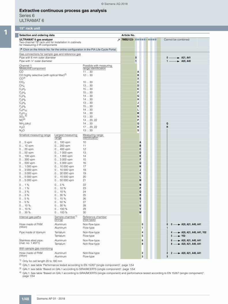
■ Selection and ordering data Article No.
ULTRAMAT 6 gas analyzerTwo-channel 19" rack unit for installation in cabinetsfor measuring 2 IR components
7MB2123- 77777 - 7777 Cannot be combined
Click on the Article No. for the online configuration in the PIA Life Cycle Portal.
Gas connections for sample gas and reference gasPipe with 6 mm outer diameter 0 0 A21, A41Pipe with ¼" outer diameter 1 1 A20, A40
Channel 1 Measured component
Possible with measuring range identification
CO 11 ... 30 ACO highly selective (with optical filter)2) 12 ... 30 BCO3) XCO2 10 ... 30 CCH4 13 ... 30 DC2H2 15 ... 30 EC2H4 15 ... 30 FC2H6 14 ... 30 GC3H6 14 ... 30 HC3H8 13 ... 30 JC4H6 15 ... 30 KC4H10 14 ... 30 LC6H14 14 ... 30 MSO2
4) 13 ... 30 NNO4) 14 ... 20, 22 PNH3 (dry) 14 ... 30 Q QH2O 17 ... 20, 22 R RN2O 13 ... 30 S
Smallest measuring range Largest measuring range
Measuring range identification
0 ... 5 vpm 0 ... 100 vpm 10 A0 ... 10 vpm 0 ... 200 vpm 11 B0 ... 20 vpm 0 ... 400 vpm 12 C0 ... 50 vpm 0 ... 1 000 vpm 13 D0 ... 100 vpm 0 ... 1 000 vpm 14 E0 ... 300 vpm 0 ... 3 000 vpm 15 F0 ... 500 vpm 0 ... 5 000 vpm 16 G0 ... 1 000 vpm 0 ... 10 000 vpm 17 H0 ... 3 000 vpm 0 ... 10 000 vpm 18 J0 ... 3 000 vpm 0 ... 30 000 vpm 19 K0 ... 5 000 vpm 0 ... 15 000 vpm 20 L0 ... 5 000 vpm 0 ... 50 000 vpm 21 M
0 ... 1 % 0 ... 3 % 22 N0 ... 1 % 0 ... 10 % 23 P0 ... 3 % 0 ... 10 % 24 Q0 ... 3 % 0 ... 30 % 25 R0 ... 5 % 0 ... 15 % 26 S0 ... 5 % 0 ... 50 % 27 T0 ... 10 % 0 ... 30 % 28 U0 ... 10 % 0 ... 100 % 29 V0 ... 30 % 0 ... 100 % 30 W
Internal gas paths Sample chamber1)
(lining)Reference chamber(flow-type)
Hose made of FKM(Viton)
Aluminum Non-flow-type 0 0 0 A20, A21, A40, A41Aluminum Flow-type 1 1
Pipe made of titanium Tantalum Non-flow-type 4 4 A20, A21, A40, A41, Y02Tantalum Flow-type 5 5 Y02
Stainless steel pipe(mat. no. 1.4571)
Aluminum Non-flow-type 6 6 A20, A21, A40, A41Tantalum Non-flow-type 8 8 A20, A21, A40, A41
With sample gas monitoring
Hose made of FKM(Viton)
Aluminum Non-flow-type 2 2 2 A20, A21, A40, A41Aluminum Flow-type 3 3
1) Only for cell length 20 to 180 mm2) QAL1: see table "Performance tested according to EN 15267 (single component)", page 1/543) QAL1: see table "Based on QAL1 according to SIRA/MCERTS (single component)", page 1/544) QAL1: See table "Based on QAL1 according to SIRA/MCERTS (single component) and performance-tested according to EN 15267 (single component)",
page 1/54
© Siemens AG 2018

1/49Siemens AP 01 · 2018
Extractive continuous process gas analysisSeries 6
ULTRAMAT 6
19" rack unit1
1) QAL1: see table "Performance tested according to EN 15267 (single component)", page 1/542) QAL1: see table "Based on QAL1 according to SIRA/MCERTS (single component)", page 1/543) QAL1: See table "Based on QAL1 according to SIRA/MCERTS (single component) and performance-tested according to EN 15267 (single component)",
page 1/54
Add-on electronics
Without 0 0 Y27, Y28
AUTOCAL function• With 8 additional digital inputs/outputs each for channel 1 1• With 8 additional digital inputs/outputs each for channel 2 2• With 8 additional digital inputs/outputs each for channel 1 and channel 2 3• With serial interface for the automotive industry (AK) 5 5 E20• With 8 additional digital inputs/outputs each for channel 1 and channel 2
and PROFIBUS PA interface6
• With 8 additional digital inputs/outputs each for channel 1 and channel 2 and PROFIBUS DP interface
7
Power supply100 ... 120 V AC, 48 ... 63 Hz 0200 ... 240 V AC, 48 ... 63 Hz 1
Channel 2 Measured component
Possible with measuring range identification
CO 11 ... 30 ACO highly selective (with optical filter)1) 12 ... 30 BCO2) XCO2 10 ... 30 CCH4 13 ... 30 DC2H2 15 ... 30 EC2H4 15 ... 30 FC2H6 14 ... 30 GC3H6 14 ... 30 HC3H8 13 ... 30 JC4H6 15 ... 30 KC4H10 14 ... 30 LC6H14 14 ... 30 MSO2
3) 13 ... 30 NNO3) 14 ... 20, 22 PNH3 (dry) 14 ... 30 Q QH2O 17 ... 20, 22 R RN2O 13 ... 30 S
Smallest measuring range Largest measuring range
Measuring range identification
0 ... 5 vpm 0 ... 100 vpm 10 A0 ... 10 vpm 0 ... 200 vpm 11 B0 ... 20 vpm 0 ... 400 vpm 12 C0 ... 50 vpm 0 ... 1 000 vpm 13 D0 ... 100 vpm 0 ... 1 000 vpm 14 E0 ... 300 vpm 0 ... 3 000 vpm 15 F0 ... 500 vpm 0 ... 5 000 vpm 16 G0 ... 1 000 vpm 0 ... 10 000 vpm 17 H0 ... 3 000 vpm 0 ... 10 000 vpm 18 J0 ... 3 000 vpm 0 ... 30 000 vpm 19 K0 ... 5 000 vpm 0 ... 15 000 vpm 20 L0 ... 5 000 vpm 0 ... 50 000 vpm 21 M
0 ... 1 % 0 ... 3 % 22 N0 ... 1 % 0 ... 10 % 23 P0 ... 3 % 0 ... 10 % 24 Q0 ... 3 % 0 ... 30 % 25 R0 ... 5 % 0 ... 15 % 26 S0 ... 5 % 0 ... 50 % 27 T0 ... 10 % 0 ... 30 % 28 U0 ... 10 % 0 ... 100 % 29 V0 ... 30 % 0 ... 100 % 30 W
Operating software and documentationGerman 0English 1French 2Spanish 3Italian 4
■ Selection and ordering data Article No.
ULTRAMAT 6 gas analyzerTwo-channel 19" rack unit for installation in cabinetsfor measuring 2 IR components
7MB2123- 77777 - 7777 Cannot be combined
© Siemens AG 2018

1/50 Siemens AP 01 · 2018
Extractive continuous process gas analysisSeries 6ULTRAMAT 6
19" rack unit1
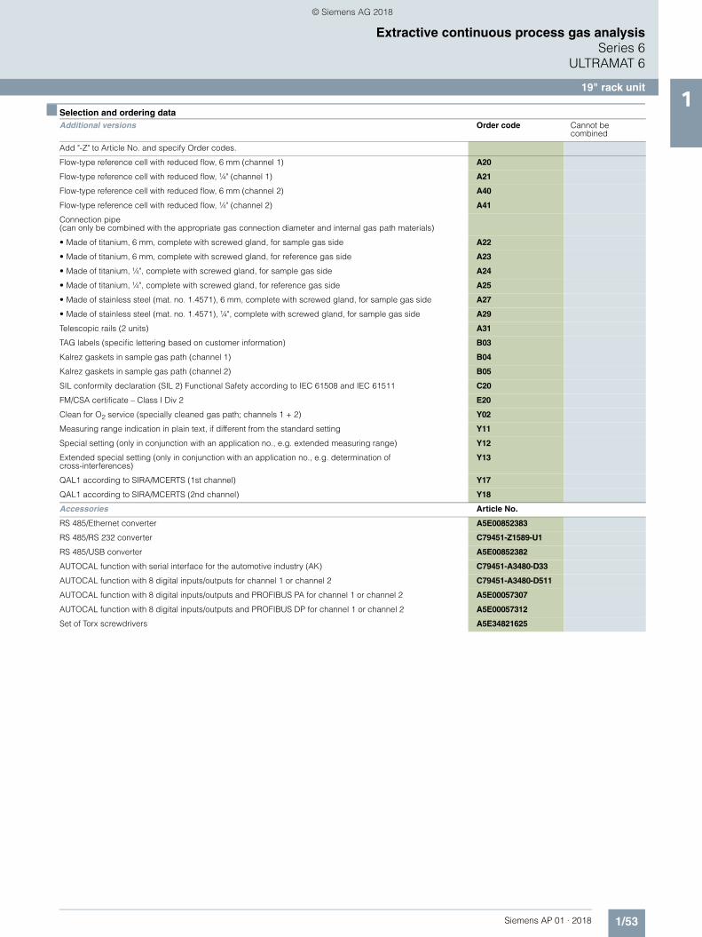
■ Selection and ordering data
Additional versions Order code Cannot be combined
Add "-Z" to Article No. and specify Order codes.
Flow-type reference cell with reduced flow, 6 mm (channel 1) A20
Flow-type reference cell with reduced flow, ¼" (channel 1) A21
Flow-type reference cell with reduced flow, 6 mm (channel 2) A40
Flow-type reference cell with reduced flow, ¼" (channel 2) A41
Connection pipe(can only be combined with the appropriate gas connection diameter and internal gas path materials)
• Made of titanium, 6 mm, complete with screwed gland, for sample gas side A22
• Made of titanium, 6 mm, complete with screwed gland, for reference gas side A23
• Made of titanium, ¼", complete with screwed gland, for sample gas side A24
• Made of titanium, ¼", complete with screwed gland, for reference gas side A25
• Made of stainless steel (mat. no. 1.4571), 6 mm, complete with screwed gland, for sample gas side A27
• Made of stainless steel (mat. no. 1.4571), ¼", complete with screwed gland, for sample gas side A29
Telescopic rails (2 units) A31
TAG labels (specific lettering based on customer information) B03
Kalrez gaskets in sample gas path (channel 1) B04
Kalrez gaskets in sample gas path (channel 2) B05
SIL conformity declaration (SIL 2) Functional Safety according to IEC 61508 and IEC 61511 C20
FM/CSA certificate – Class I Div 2 E20
Clean for O2 service (specially cleaned gas path; channels 1 + 2) Y02
Measuring range indication in plain text, if different from the standard setting Y11
Special setting (only in conjunction with an application no., e.g. extended measuring range) Y12
Extended special setting (only in conjunction with an application no., e.g. determination of cross-interferences)
Y13
QAL1 according to SIRA/MCERTS (1st channel) Y17
QAL1 according to SIRA/MCERTS (2nd channel) Y18
Performance-tested according to EN 15267 (1st channel) Y27
Performance-tested according to EN 15267 (2nd channel) Y28
Accessories Article No.
RS 485/Ethernet converter A5E00852383
RS 485/RS 232 converter C79451-Z1589-U1
RS 485/USB converter A5E00852382
AUTOCAL function with serial interface for the automotive industry (AK) C79451-A3480-D33
AUTOCAL function with 8 digital inputs/outputs for channel 1 or channel 2 C79451-A3480-D511
AUTOCAL function with 8 digital inputs/outputs and PROFIBUS PA for channel 1 or channel 2 A5E00057307
AUTOCAL function with 8 digital inputs/outputs and PROFIBUS DP for channel 1 or channel 2 A5E00057312
Set of Torx screwdrivers A5E34821625
© Siemens AG 2018

1/51Siemens AP 01 · 2018
Extractive continuous process gas analysisSeries 6
ULTRAMAT 6
19" rack unit1
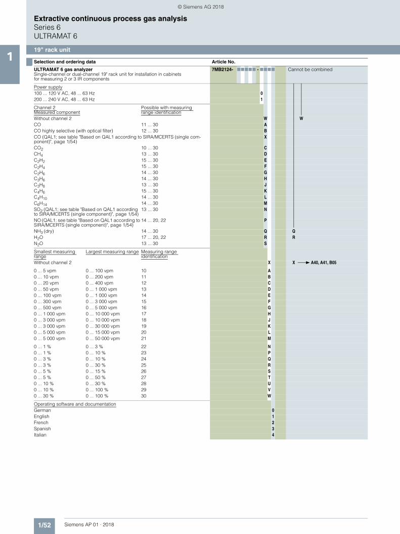
■ Selection and ordering data Article No.
ULTRAMAT 6 gas analyzerSingle-channel or dual-channel 19" rack unit for installation in cabinetsfor measuring 2 or 3 IR components
7MB2124- 77777 - 7777 Cannot be combined
Click on the Article No. for the online configuration in the PIA Life Cycle Portal.
Gas connections for sample gas and reference gasPipe with 6 mm outer diameter 0 0 A21, A41Pipe with ¼" outer diameter 1 1 A20, A40
Measured component Smallest measuring rangeLargest measuring range
CO 0 ... 100 vpm 0 ... 1 000 vpm A ANO 0 ... 100 vpm 0 ... 1 000 vpm
CO 0 ... 300 vpm 0 ... 3 000 vpm A BNO 0 ... 300 vpm 0 ... 3 000 vpm
CO 0 ... 1 000 vpm 0 ... 10 000 vpm A CNO 0 ... 1 000 vpm 0 ... 10 000 vpm
For CO/NO (QAL1; see table "Based on QAL1 according to SIRA/MCERTS (2 components in series)", page 1/54)
CO2 0 ... 100 vpm 0 ... 1 000 vpm B ACO 0 ... 100 vpm 0 ... 1 000 vpm
CO2 0 ... 300 vpm 0 ... 3 000 vpm B BCO 0 ... 300 vpm 0 ... 3 000 vpm
CO2 0 ... 1 000 vpm 0 ... 10 000 vpm B CCO 0 ... 1 000 vpm 0 ... 10 000 vpm
CO2 0 ... 3 000 vpm 0 ... 30 000 vpm B DCO 0 ... 3 000 vpm 0 ... 30 000 vpm
CO2 0 ... 1 % 0 ... 10 % B ECO 0 ... 1 % 0 ... 10 %
CO2 0 ... 3 % 0 ... 30 % B FCO 0 ... 3 % 0 ... 30 %
CO2 0 ... 10 % 0 ... 100 % B GCO 0 ... 10 % 0 ... 100 %
CO2 0 ... 10 % 0 ... 100 % C GCH4 0 ... 10 % 0 ... 100 %
CO2 0 ... 300 vpm 0 ... 3 000 vpm D BNO 0 ... 300 vpm 0 ... 3 000 vpm
Internal gas paths Sample chamber1)
(lining)Reference chamber(flow-type)
Hose made of FKM(Viton)
Aluminum Non-flow-type 0 0 0 A20, A21, A40, A41Aluminum Flow-type 1 1
Pipe made of titanium Tantalum Non-flow-type 4 4 A20, A21, A40, A41, Y02Tantalum Flow-type 5 5 Y02
Stainless steel pipe(mat. no. 1.4571)
Aluminum Non-flow-type 6 6 A20, A21, A40, A41Tantalum Non-flow-type 8 8 A20, A21, A40, A41
With sample gas monitoringHose made of FKM(Viton)
Aluminum Non-flow-type 2 2 2 A20, A21, A40, A41Aluminum Flow-type 3 3
Add-on electronicsWithout 0AUTOCAL function• With 8 additional digital inputs/outputs each for channel 1 1• With 8 additional digital inputs/outputs each for channel 1 and channel 2 2 2• With serial interface for the automotive industry (AK), channel 1 3 3 E20• With serial interface for the automotive industry (AK),
channel 1 and channel 24 4 E20
• With 8 additional digital inputs/outputs for channel 1and PROFIBUS PA interface
5
• With 8 additional digital inputs/outputs each for channel 1 and channel 2 and PROFIBUS PA interface
6 6
• With 8 additional digital inputs/outputs for channel 1and PROFIBUS DP interface
7
• With 8 additional digital inputs/outputs each for channel 1 and channel 2 and PROFIBUS DP interface
8 8
1) Only for cell length 20 to 180 mm
© Siemens AG 2018
1/52 Siemens AP 01 · 2018
Extractive continuous process gas analysisSeries 6ULTRAMAT 6
19" rack unit1
Power supply100 ... 120 V AC, 48 ... 63 Hz 0200 ... 240 V AC, 48 ... 63 Hz 1
Channel 2 Measured component
Possible with measuring range identification
Without channel 2 W WCO 11 ... 30 ACO highly selective (with optical filter) 12 ... 30 BCO (QAL1; see table "Based on QAL1 according to SIRA/MCERTS (single com-ponent)", page 1/54)
X
CO2 10 ... 30 CCH4 13 ... 30 DC2H2 15 ... 30 EC2H4 15 ... 30 FC2H6 14 ... 30 GC3H6 14 ... 30 HC3H8 13 ... 30 JC4H6 15 ... 30 KC4H10 14 ... 30 LC6H14 14 ... 30 MSO2 (QAL1; see table "Based on QAL1 according to SIRA/MCERTS (single component)", page 1/54)
13 ... 30 N
NO (QAL1; see table "Based on QAL1 according to SIRA/MCERTS (single component)", page 1/54)
14 ... 20, 22 P
NH3 (dry) 14 ... 30 Q QH2O 17 ... 20, 22 R RN2O 13 ... 30 S
Smallest measuring range
Largest measuring range Measuring range identification
Without channel 2 X X A40, A41, B05
0 ... 5 vpm 0 ... 100 vpm 10 A0 ... 10 vpm 0 ... 200 vpm 11 B0 ... 20 vpm 0 ... 400 vpm 12 C0 ... 50 vpm 0 ... 1 000 vpm 13 D0 ... 100 vpm 0 ... 1 000 vpm 14 E0 ... 300 vpm 0 ... 3 000 vpm 15 F0 ... 500 vpm 0 ... 5 000 vpm 16 G0 ... 1 000 vpm 0 ... 10 000 vpm 17 H0 ... 3 000 vpm 0 ... 10 000 vpm 18 J0 ... 3 000 vpm 0 ... 30 000 vpm 19 K0 ... 5 000 vpm 0 ... 15 000 vpm 20 L0 ... 5 000 vpm 0 ... 50 000 vpm 21 M
0 ... 1 % 0 ... 3 % 22 N0 ... 1 % 0 ... 10 % 23 P0 ... 3 % 0 ... 10 % 24 Q0 ... 3 % 0 ... 30 % 25 R0 ... 5 % 0 ... 15 % 26 S0 ... 5 % 0 ... 50 % 27 T0 ... 10 % 0 ... 30 % 28 U0 ... 10 % 0 ... 100 % 29 V0 ... 30 % 0 ... 100 % 30 W
Operating software and documentationGerman 0English 1French 2Spanish 3Italian 4
■ Selection and ordering data Article No.
ULTRAMAT 6 gas analyzerSingle-channel or dual-channel 19" rack unit for installation in cabinetsfor measuring 2 or 3 IR components
7MB2124- 77777 - 7777 Cannot be combined
© Siemens AG 2018
1/53Siemens AP 01 · 2018
Extractive continuous process gas analysisSeries 6
ULTRAMAT 6
19" rack unit1
■ Selection and ordering data Additional versions Order code Cannot be
combined
Add "-Z" to Article No. and specify Order codes.
Flow-type reference cell with reduced flow, 6 mm (channel 1) A20
Flow-type reference cell with reduced flow, ¼" (channel 1) A21
Flow-type reference cell with reduced flow, 6 mm (channel 2) A40
Flow-type reference cell with reduced flow, ¼" (channel 2) A41
Connection pipe(can only be combined with the appropriate gas connection diameter and internal gas path materials)
• Made of titanium, 6 mm, complete with screwed gland, for sample gas side A22
• Made of titanium, 6 mm, complete with screwed gland, for reference gas side A23
• Made of titanium, ¼", complete with screwed gland, for sample gas side A24
• Made of titanium, ¼", complete with screwed gland, for reference gas side A25
• Made of stainless steel (mat. no. 1.4571), 6 mm, complete with screwed gland, for sample gas side A27
• Made of stainless steel (mat. no. 1.4571), ¼", complete with screwed gland, for sample gas side A29
Telescopic rails (2 units) A31
TAG labels (specific lettering based on customer information) B03
Kalrez gaskets in sample gas path (channel 1) B04
Kalrez gaskets in sample gas path (channel 2) B05
SIL conformity declaration (SIL 2) Functional Safety according to IEC 61508 and IEC 61511 C20
FM/CSA certificate – Class I Div 2 E20
Clean for O2 service (specially cleaned gas path; channels 1 + 2) Y02
Measuring range indication in plain text, if different from the standard setting Y11
Special setting (only in conjunction with an application no., e.g. extended measuring range) Y12
Extended special setting (only in conjunction with an application no., e.g. determination of cross-interferences)
Y13
QAL1 according to SIRA/MCERTS (1st channel) Y17
QAL1 according to SIRA/MCERTS (2nd channel) Y18
Accessories Article No.
RS 485/Ethernet converter A5E00852383
RS 485/RS 232 converter C79451-Z1589-U1
RS 485/USB converter A5E00852382
AUTOCAL function with serial interface for the automotive industry (AK) C79451-A3480-D33
AUTOCAL function with 8 digital inputs/outputs for channel 1 or channel 2 C79451-A3480-D511
AUTOCAL function with 8 digital inputs/outputs and PROFIBUS PA for channel 1 or channel 2 A5E00057307
AUTOCAL function with 8 digital inputs/outputs and PROFIBUS DP for channel 1 or channel 2 A5E00057312
Set of Torx screwdrivers A5E34821625
© Siemens AG 2018
1/54 Siemens AP 01 · 2018
Extractive continuous process gas analysisSeries 6ULTRAMAT 6
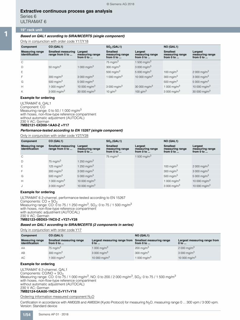
19" rack unit1 Based on QAL1 according to SIRA/MCERTS (single component)
Only in conjunction with order code Y17/Y18
Example for ordering
ULTRAMAT 6, QAL1Component: COMeasuring range: 0 to 50 / 1 000 mg/m3
with hoses, non-flow-type reference compartmentwithout automatic adjustment (AUTOCAL)230 V AC; German7MB2121-0XD00-1AA0-Z +Y17
Performance-tested according to EN 15267 (single component)
Only in conjunction with order code Y27/Y28
Example for ordering
ULTRAMAT 6 2-channel, performance-tested according to EN 15267Components: CO + SO2Measuring range: CO: 0 to 75 / 1 250 mg/m3, SO2: 0 to 75 / 1 500 mg/m3
with hoses, non-flow-type reference compartmentwith automatic adjustment (AUTOCAL)230 V AC; German7MB2123-0BD03-1NC0-Z +Y27+Y28
Based on QAL1 according to SIRA/MCERTS (2 components in series)
Only in conjunction with order code Y17
Example for ordering
ULTRAMAT 6 2-channel, QAL1Components: CO/NO + SO2Measuring range: CO: 0 to 75 / 1 000 mg/m3, NO: 0 to 200 / 2 000 mg/m3, SO2: 0 to 75 / 1 500 mg/m3
with hoses, non-flow-type reference compartmentwithout automatic adjustment (AUTOCAL)230 V AC; German7MB2124-0AA00-1NC0-Z+Y17+Y18
Ordering information measured component N2O
Certification in accordance with AM0028 and AM0034 (Kyoto Protocol) for measuring N2O, measuring range 0 ... 300 vpm / 3 000 vpm.Version: Standard device
Component CO (QAL1) SO2 (QAL1) NO (QAL1)
Measuring range identification
Smallest measuring range from 0 to ...
Largest measuring range from 0 to ...
Smallest measuring range from 0 to ...
Largest measuring range from 0 to ...
Smallest measuring range from 0 to ...
Largest measuring range from 0 to ...
C 75 mg/m3 1 500 mg/m3
D 50 mg/m3 1 000 mg/m3 300 mg/m3 3 000 mg/m3
E 500 mg/m3 5 000 mg/m3 100 mg/m3 2 000 mg/m3
F 300 mg/m3 3 000 mg/m3 1 000 mg/m3 10 000 mg/m3 300 mg/m3 3 000 mg/m3
G 500 mg/m3 5 000 mg/m3 500 mg/m3 5 000 mg/m3
H 1 000 mg/m3 10 000 mg/m3 3 000 mg/m3 30 000 mg/m3 1 000 mg/m3 10 000 mg/m3
K 3 000 mg/m3 30 000 mg/m3 10 g/m3 100 g/m3 3 000 mg/m3 30 000 mg/m3
Component CO (QAL1) SO2 (QAL1) NO (QAL1)
Measuring range identification
Smallest measuring range from 0 to ...
Largest measuring range from 0 to ...
Smallest measuring range from 0 to ...
Largest measuring range from 0 to ...
Smallest measuring range from 0 to ...
Largest measuring range from 0 to ...
C 75 mg/m3 1 500 mg/m3
D 75 mg/m3 1 250 mg/m3
E 125 mg/m3 1 250 mg/m3 100 mg/m3 2 000 mg/m3
F 300 mg/m3 3 000 mg/m3 300 mg/m3 3 000 mg/m3
G 500 mg/m3 5 000 mg/m3 500 mg/m3 5 000 mg/m3
H 1 000 mg/m3 10 000 mg/m3 1 000 mg/m3 10 000 mg/m3
J 3 000 mg/m3 10 000 mg/m3 3 000 mg/m3 10 000 mg/m3
Component CO (QAL1) NO (QAL1)
Measuring range identification
Smallest measuring range from 0 to ...
Largest measuring range from 0 to ...
Smallest measuring range from 0 to ...
Largest measuring range from 0 to ...
AA 75 mg/m3 1 000 mg/m3 200 mg/m3 2 000 mg/m3
AB 300 mg/m3 3 000 mg/m3 300 mg/m3 3 000 mg/m3
AC 1 000 mg/m3 10 000 mg/m3 1 000 mg/m3 10 000 mg/m3
© Siemens AG 2018
1/55Siemens AP 01 · 2018
Extractive continuous process gas analysisSeries 6
ULTRAMAT 6
19" rack unit1
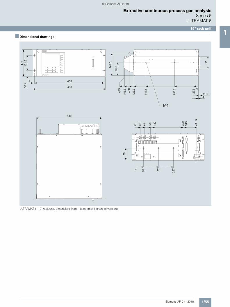
■ Dimensional drawings
ULTRAMAT 6, 19" rack unit, dimensions in mm (example: 1-channel version)
s
© Siemens AG 2018
1/56 Siemens AP 01 · 2018
Extractive continuous process gas analysisSeries 6ULTRAMAT 6
19" rack unit1
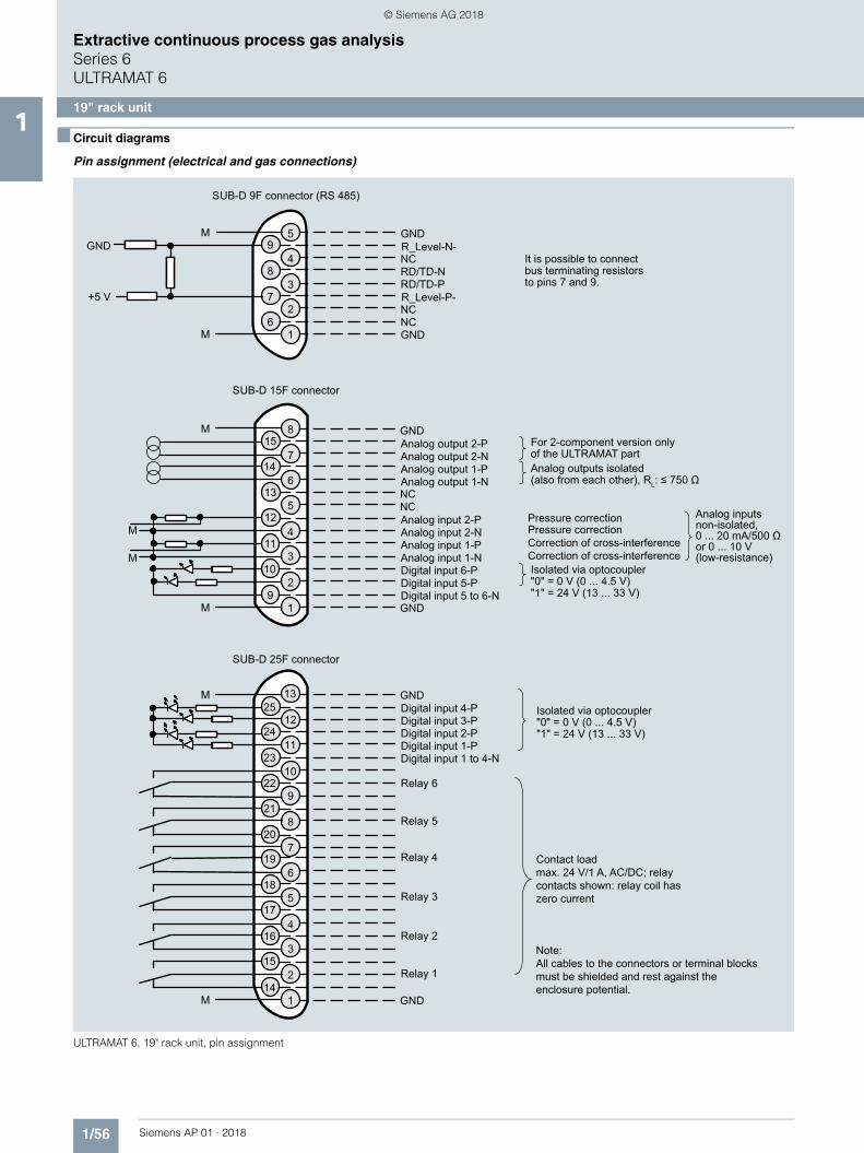
■ Circuit diagrams
Pin assignment (electrical and gas connections)
ULTRAMAT 6, 19" rack unit, pin assignment
M
GND
GND
M
GND
NCNC
GND
M
M
M
M
NC
RD/TD-PRD/TD-N
NC
GNDNC
GNDM
M
GND
+5 V
4
512
13
14
15
1
2
3
6
7
8
9
10
11
12
13
7
8
9
10
11
4
517
18
19
1
2
3
6
16
21
14
20
15
22
23
24
25
1
2
3
4
5
6
7
8
9
Isolated via optocoupler"0" = 0 V (0 ... 4.5 V)"1" = 24 V (13 ... 33 V)
Digital input 1 to 4-NDigital input 1-PDigital input 2-PDigital input 3-PDigital input 4-P
Relay 1
Relay 2
Relay 3
Relay 4
Relay 5
Relay 6
SUB-D 25F connector
Correction of cross-interferenceCorrection of cross-interference
Pressure correctionPressure correction
Analog outputs isolated(also from each other), RL: ≤ 750 Ω
Analog inputsnon-isolated,0 ... 20 mA/500 Ωor 0 ... 10 V(low-resistance)
Analog output 2-P
Analog output 1-NAnalog output 1-PAnalog output 2-N
Analog input 2-PAnalog input 2-NAnalog input 1-PAnalog input 1-NDigital input 6-PDigital input 5-PDigital input 5 to 6-N
SUB-D 15F connector
R_Level-P-
R_Level-N-It is possible to connect bus terminating resistorsto pins 7 and 9.
SUB-D 9F connector (RS 485)
For 2-component version onlyof the ULTRAMAT part
Isolated via optocoupler"0" = 0 V (0 ... 4.5 V)"1" = 24 V (13 ... 33 V)
Contact load max. 24 V/1 A, AC/DC; relay contacts shown: relay coil has zero current
© Siemens AG 2018
1/57Siemens AP 01 · 2018
Extractive continuous process gas analysisSeries 6
ULTRAMAT 6
19" rack unit1
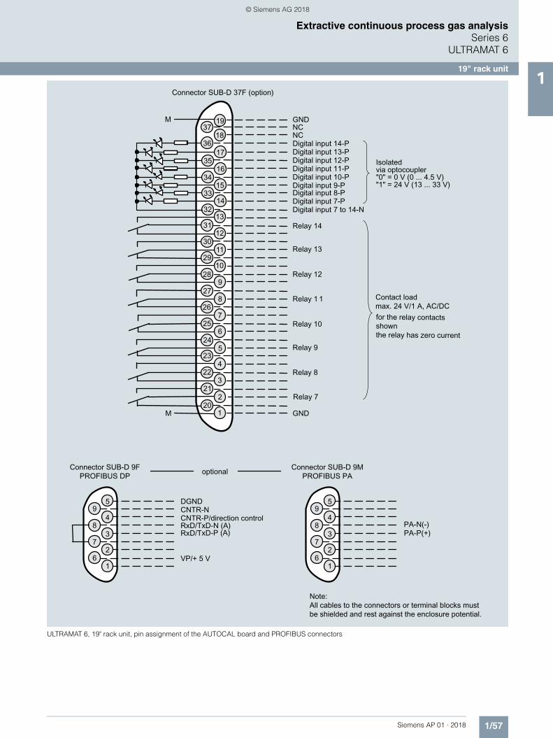
ULTRAMAT 6, 19" rack unit, pin assignment of the AUTOCAL board and PROFIBUS connectors
© Siemens AG 2018
1/58 Siemens AP 01 · 2018
Extractive continuous process gas analysisSeries 6ULTRAMAT 6
19" rack unit1
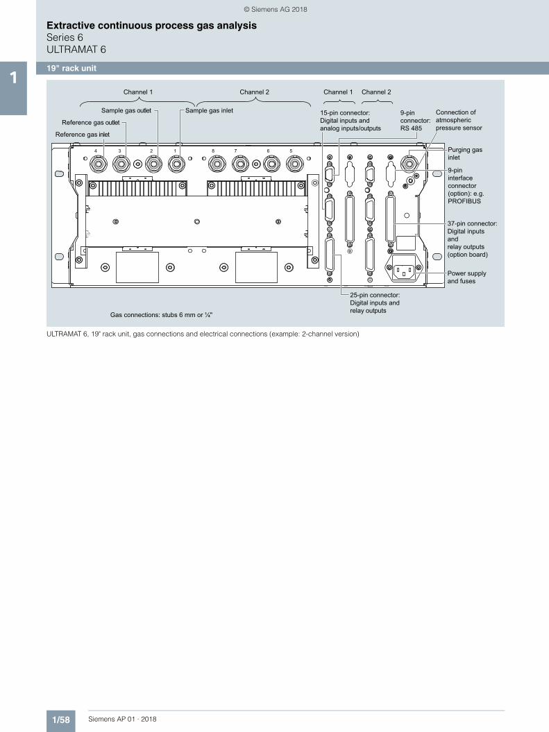
ULTRAMAT 6, 19" rack unit, gas connections and electrical connections (example: 2-channel version)
Gas connections: stubs 6 mm or ¼"
9-pininterface connector (option): e.g.PROFIBUS
Power supplyand fuses
37-pin connector:Digital inputs andrelay outputs(option board)
25-pin connector:Digital inputs andrelay outputs
Channel 1 Channel 2
9-pinconnector:RS 485
15-pin connector:Digital inputs andanalog inputs/outputs
Sample gas inlet
Reference gas inlet
Sample gas outlet
Reference gas outlet
Channel 2Channel 1
Purging gasinlet
Connection of atmospheric pressure sensor
1234 8 7 6 5
© Siemens AG 2018
1/59Siemens AP 01 · 2018
Extractive continuous process gas analysisSeries 6
ULTRAMAT 6
Field device1
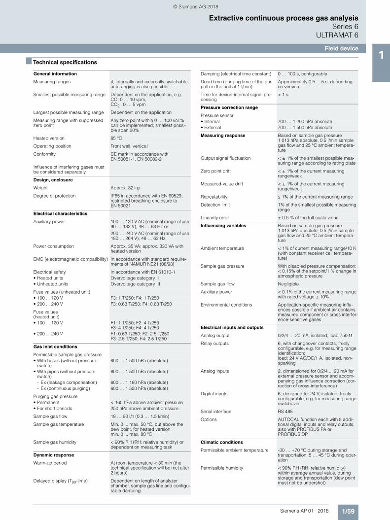
■ Technical specifications
General information
Measuring ranges 4, internally and externally switchable; autoranging is also possible
Smallest possible measuring range Dependent on the application, e.g. CO: 0 … 10 vpm, CO2 : 0 … 5 vpm
Largest possible measuring range Dependent on the application
Measuring range with suppressed zero point
Any zero point within 0 … 100 vol.% can be implemented; smallest possi-ble span 20%
Heated version 65 °C
Operating position Front wall, vertical
Conformity CE mark in accordance with EN 50081-1, EN 50082-2
Influence of interfering gases must be considered separately
Design, enclosure
Weight Approx. 32 kg
Degree of protection IP65 in accordance with EN 60529, restricted breathing enclosure to EN 50021
Electrical characteristics
Auxiliary power 100 … 120 V AC (nominal range of use 90 … 132 V), 48 … 63 Hz or
200 … 240 V AC (nominal range of use 180 … 264 V), 48 … 63 Hz
Power consumption Approx. 35 VA; approx. 330 VA with heated version
EMC (electromagnetic compatibility) In accordance with standard require-ments of NAMUR NE21 (08/98)
Electrical safety In accordance with EN 61010-1• Heated units Overvoltage category II• Unheated units Overvoltage category III
Fuse values (unheated unit)• 100 ... 120 V F3: 1 T/250; F4: 1 T/250• 200 ... 240 V F3: 0.63 T/250; F4: 0.63 T/250
Fuse values(heated unit)• 100 ... 120 V F1: 1 T/250; F2: 4 T/250
F3: 4 T/250; F4: 4 T/250• 200 ... 240 V F1: 0.63 T/250; F2: 2.5 T/250
F3: 2.5 T/250; F4: 2.5 T/250
Gas inlet conditions
Permissible sample gas pressure• With hoses (without pressure
switch)600 … 1 500 hPa (absolute)
• With pipes (without pressure switch)
600 … 1 500 hPa (absolute)
- Ex (leakage compensation) 600 … 1 160 hPa (absolute)- Ex (continuous purging) 600 … 1 500 hPa (absolute)
Purging gas pressure• Permanent < 165 hPa above ambient pressure• For short periods 250 hPa above ambient pressure
Sample gas flow 18 … 90 l/h (0.3 … 1.5 l/min)
Sample gas temperature Min. 0 ... max. 50 °C, but above the dew point, for heated version min. 0 ... max. 80 °C
Sample gas humidity < 90% RH (RH: relative humidity) or dependent on measuring task
Dynamic response
Warm-up period At room temperature < 30 min (the technical specification will be met after 2 hours)
Delayed display (T90-time) Dependent on length of analyzer chamber, sample gas line and configu-rable damping
Damping (electrical time constant) 0 … 100 s, configurable
Dead time (purging time of the gas path in the unit at 1 l/min)
Approximately 0.5 ... 5 s, depending on version
Time for device-internal signal pro-cessing
< 1 s
Pressure correction range
Pressure sensor• Internal 700 … 1 200 hPa absolute• External 700 … 1 500 hPa absolute
Measuring response Based on sample gas pressure 1 013 hPa absolute, 0.5 l/min sample gas flow and 25 °C ambient tempera-ture
Output signal fluctuation < ± 1% of the smallest possible mea-suring range according to rating plate
Zero point drift < ± 1% of the current measuring range/week
Measured-value drift < ± 1% of the current measuring range/week
Repeatability 1% of the current measuring range
Detection limit 1% of the smallest possible measuring range
Linearity error ± 0.5 % of the full-scale value
Influencing variables Based on sample gas pressure 1 013 hPa absolute, 0.5 l/min sample gas flow and 25 °C ambient tempera-ture
Ambient temperature < 1% of current measuring range/10 K (with constant receiver cell tempera-ture)
Sample gas pressure With disabled pressure compensation: < 0.15% of the setpoint/1 % change in atmospheric pressure
Sample gas flow Negligible
Auxiliary power < 0.1% of the current measuring range with rated voltage ± 10%
Environmental conditions Application-specific measuring influ-ences possible if ambient air contains measured component or cross interfer-ence-sensitive gases
Electrical inputs and outputs
Analog output 0/2/4 … 20 mA, isolated; load 750
Relay outputs 6, with changeover contacts, freely configurable, e.g. for measuring range identification; load: 24 V AC/DC/1 A, isolated, non-sparking
Analog inputs 2, dimensioned for 0/2/4 ... 20 mA for external pressure sensor and accom-panying gas influence correction (cor-rection of cross-interference)
Digital inputs 6, designed for 24 V, isolated, freely configurable, e.g. for measuring range switchover
Serial interface RS 485
Options AUTOCAL function each with 8 addi-tional digital inputs and relay outputs, also with PROFIBUS PA or PROFIBUS DP
Climatic conditions
Permissible ambient temperature -30 … +70 °C during storage and transportation; 5 … 45 °C during oper-ation
Permissible humidity < 90% RH (RH: relative humidity) within average annual value, during storage and transportation (dew point must not be undershot)
© Siemens AG 2018
1/60 Siemens AP 01 · 2018
Extractive continuous process gas analysisSeries 6ULTRAMAT 6
Field device1
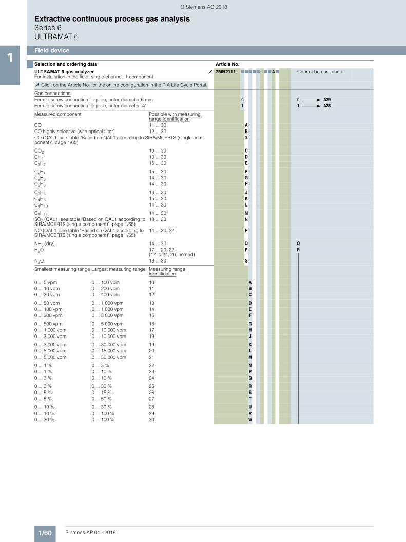
■ Selection and ordering data Article No.
ULTRAMAT 6 gas analyzerFor installation in the field, single-channel, 1 component
7MB2111- 77777 - 77 A7 Cannot be combined
Click on the Article No. for the online configuration in the PIA Life Cycle Portal.
Gas connectionsFerrule screw connection for pipe, outer diameter 6 mm 0 0 A29Ferrule screw connection for pipe, outer diameter ¼" 1 1 A28
Measured component Possible with measuring range identification
CO 11 ... 30 ACO highly selective (with optical filter) 12 ... 30 BCO (QAL1; see table "Based on QAL1 according to SIRA/MCERTS (single com-ponent)", page 1/65)
X
CO2 10 ... 30 CCH4 13 ... 30 DC2H2 15 ... 30 E
C2H4 15 ... 30 FC2H6 14 ... 30 GC3H6 14 ... 30 H
C3H8 13 ... 30 JC4H6 15 ... 30 KC4H10 14 ... 30 L
C6H14 14 ... 30 MSO2 (QAL1; see table "Based on QAL1 according to SIRA/MCERTS (single component)", page 1/65)
13 ... 30 N
NO (QAL1; see table "Based on QAL1 according to SIRA/MCERTS (single component)", page 1/65)
14 ... 20, 22 P
NH3 (dry) 14 ... 30 Q QH2O 17 ... 20; 22
(17 to 24, 26; heated)R R
N2O 13 ... 30 S
Smallest measuring range Largest measuring range Measuring range identification
0 ... 5 vpm 0 ... 100 vpm 10 A0 ... 10 vpm 0 ... 200 vpm 11 B0 ... 20 vpm 0 ... 400 vpm 12 C
0 ... 50 vpm 0 ... 1 000 vpm 13 D0 ... 100 vpm 0 ... 1 000 vpm 14 E0 ... 300 vpm 0 ... 3 000 vpm 15 F
0 ... 500 vpm 0 ... 5 000 vpm 16 G0 ... 1 000 vpm 0 ... 10 000 vpm 17 H0 ... 3 000 vpm 0 ... 10 000 vpm 19 J
0 ... 3 000 vpm 0 ... 30 000 vpm 19 K0 ... 5 000 vpm 0 ... 15 000 vpm 20 L0 ... 5 000 vpm 0 ... 50 000 vpm 21 M
0 ... 1 % 0 ... 3 % 22 N0 ... 1 % 0 ... 10 % 23 P0 ... 3 % 0 ... 10 % 24 Q
0 ... 3 % 0 ... 30 % 25 R0 ... 5 % 0 ... 15 % 26 S0 ... 5 % 0 ... 50 % 27 T
0 ... 10 % 0 ... 30 % 28 U0 ... 10 % 0 ... 100 % 29 V0 ... 30 % 0 ... 100 % 30 W
© Siemens AG 2018
1/61Siemens AP 01 · 2018
Extractive continuous process gas analysisSeries 6
ULTRAMAT 6
Field device1
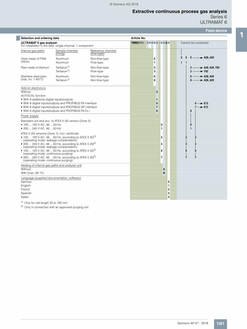
1) Only for cell length 20 to 180 mm2) Only in connection with an approved purging unit
Internal gas paths Sample chamber (lining)
Reference chamber(flow-type)
Hose made of FKM(Viton)
Aluminum Non-flow-type 0 0 0 0 A28, A29
Aluminum Flow-type 1 1 1
Pipe made of titanium Tantalum1) Non-flow-type 2 2 A28, A29, Y02Tantalum1) Flow-type 3 3 Y02
Stainless steel pipe(mat. no. 1.4571)
Aluminum Non-flow-type 6 6 A28, A29Tantalum1) Non-flow-type 8 8 A28, A29
Add-on electronicsWithout 0AUTOCAL function• With 8 additional digital inputs/outputs 1• With 8 digital inputs/outputs and PROFIBUS PA interface 6 6 E12• With 8 digital inputs/outputs and PROFIBUS DP interface 7 7 E12• With 8 digital inputs/outputs and PROFIBUS PA Ex i 8 8
Power supply
Standard unit and acc. to ATEX II 3G version (Zone 2)• 100 ... 120 V AC, 48 ... 63 Hz 0 0• 200 ... 240 V AC, 48 ... 63 Hz 1 1
ATEX II 2G versions (Zone 1), incl. certificate• 100 ... 120 V AC, 48 ... 63 Hz, according to ATEX II 2G2)
(operating mode: leakage compensation)2 2 2
• 200 ... 240 V AC, 48 ... 63 Hz, according to ATEX II 2G2)
(operating mode: leakage compensation)3 3 3
• 100 ... 120 V AC, 48 ... 63 Hz, according to ATEX II 2G2)
(operating mode: continuous purging)6 6 6
• 200 ... 240 V AC, 48 ... 63 Hz, according to ATEX II 2G2)
(operating mode: continuous purging)7 7 7
Heating of internal gas paths and analyzer unitWithout AWith (max. 65 °C) B
Language (supplied documentation, software)German 0English 1French 2Spanish 3Italian 4
■ Selection and ordering data Article No.
ULTRAMAT 6 gas analyzerFor installation in the field, single-channel, 1 component
7MB2111- 77777 - 77 A7 Cannot be combined
© Siemens AG 2018
1/62 Siemens AP 01 · 2018
Extractive continuous process gas analysisSeries 6ULTRAMAT 6
Field device1
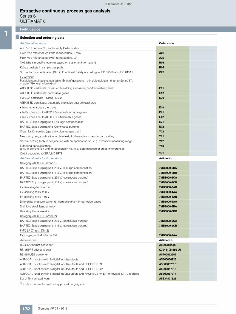
■ Selection and ordering data
1) Only in connection with an approved purging unit
Additional versions Order code
Add "-Z" to Article No. and specify Order codes.
Flow-type reference cell with reduced flow, 6 mm A28
Flow-type reference cell with reduced flow, ¼" A29
TAG labels (specific lettering based on customer information) B03
Kalrez gaskets in sample gas path B04
SIL conformity declaration (SIL 2) Functional Safety according to IEC 61508 and IEC 61511 C20
Ex versionsPossible combinations: see table "Ex configurations – principle selection criteria (Series 6)",chapter "General information"
ATEX II 3G certificate; restricted breathing enclosure, non-flammable gases E11
ATEX II 3G certificate; flammable gases E12
FM/CSA certificate – Class I Div 2 E20
ATEX II 3D certificate; potentially explosive dust atmospheres
• In non-hazardous gas zone E40
• In Ex zone acc. to ATEX II 3G, non-flammable gases E41
• In Ex zone acc. to ATEX II 3G, flammable gases1) E42
BARTEC Ex p purging unit "Leakage compensation" E71
BARTEC Ex p purging unit "Continuous purging" E72
Clean for O2 service (specially cleaned gas path) Y02
Measuring range indication in plain text, if different from the standard setting Y11
Special setting (only in conjunction with an application no., e.g. extended measuring range) Y12
Extended special setting (only in conjunction with an application no., e.g. determination of cross-interferences)
Y13
QAL1 according to SIRA/MCERTS Y17
Additional units for Ex versions Article No.
Category ATEX II 2G (zone 1)
BARTEC Ex p purging unit, 230 V, "leakage compensation" 7MB8000-2BA
BARTEC Ex p purging unit, 115 V, "leakage compensation" 7MB8000-2BB
BARTEC Ex p purging unit, 230 V, "continuous purging" 7MB8000-2CA
BARTEC Ex p purging unit, 115 V, "continuous purging" 7MB8000-2CB
Ex i isolating transformer 7MB8000-3AB
Ex isolating relay, 230 V 7MB8000-4AA
Ex isolating relay, 110 V 7MB8000-4AB
Differential pressure switch for corrosive and non-corrosive gases 7MB8000-5AA
Stainless steel flame arrestor 7MB8000-6BA
Hastelloy flame arrestor 7MB8000-6BB
Category ATEX II 3G (Zone 2)
BARTEC Ex p purging unit, 230 V, "continuous purging" 7MB8000-2CA
BARTEC Ex p purging unit, 115 V, "continuous purging" 7MB8000-2CB
FM/CSA (Class I Div. 2)
Ex purging unit MiniPurge FM 7MB8000-1AA
Accessories Article No.
RS 485/Ethernet converter A5E00852383
RS 485/RS 232 converter C79451-Z1589-U1
RS 485/USB converter A5E00852382
AUTOCAL function with 8 digital inputs/outputs A5E00064223
AUTOCAL function with 8 digital inputs/outputs and PROFIBUS PA A5E00057315
AUTOCAL function with 8 digital inputs/outputs and PROFIBUS DP A5E00057318
AUTOCAL function with 8 digital inputs/outputs and PROFIBUS PA Ex i (firmware 4.1.10 required) A5E00057317
Set of Torx screwdrivers A5E34821625
© Siemens AG 2018

1/63Siemens AP 01 · 2018
Extractive continuous process gas analysisSeries 6
ULTRAMAT 6
Field device1
■ Selection and ordering data Article No.
ULTRAMAT 6 gas analyzerFor installation in the field, single-channel, 2 components
7MB2112- 77777 - 77 A7 Cannot be combined
Click on the Article No. for the online configuration in the PIA Life Cycle Portal.
Gas connectionsFerrule screw connection for pipe, outer diameter 6 mm 0 0 A29Ferrule screw connection for pipe, outer diameter ¼" 1 1 A28
Measured component Smallest measuring range Largest measuring range
CO 0 ... 100 vpm 0 ... 1 000 vpm A ANO 0 ... 100 vpm 0 ... 1 000 vpm
CO 0 ... 300 vpm 0 ... 3 000 vpm A BNO 0 ... 300 vpm 0 ... 3 000 vpm
CO 0 ... 1 000 vpm 0 ... 10 000 vpm A CNO 0 ... 1 000 vpm 0 ... 10 000 vpmFor CO/NO (QAL1; see table "Based on QAL1 according to SIRA/MCERTS (2 components in series)", page 1/65)
CO2 0 ... 100 vpm 0 ... 1 000 vpm B ACO 0 ... 100 vpm 0 ... 1 000 vpm
CO2 0 ... 300 vpm 0 ... 3 000 vpm B BCO 0 ... 300 vpm 0 ... 3 000 vpm
CO2 0 ... 1 000 vpm 0 ... 10 000 vpm B CCO 0 ... 1 000 vpm 0 ... 10 000 vpm
CO2 0 ... 3 000 vpm 0 ... 30 000 vpm B DCO 0 ... 3 000 vpm 0 ... 30 000 vpm
CO2 0 ... 1 % 0 ... 10 % B ECO 0 ... 1 % 0 ... 10 %
CO2 0 ... 3 % 0 ... 30 % B FCO 0 ... 3 % 0 ... 30 %
CO2 0 ... 10 % 0 ... 100 % B GCO 0 ... 10 % 0 ... 100 %
CO2 0 ... 10 % 0 ... 100 % C GCH4 0 ... 10 % 0 ... 100 %
CO2 0 ... 100 vpm 0 ... 1 000 vpm D ANO 0 ... 100 vpm 0 ... 1 000 vpm
CO2 0 ... 300 vpm 0 ... 3 000 vpm D BNO 0 ... 300 vpm 0 ... 3 000 vpmInternal gas paths Sample chamber (lining) Reference chamber (flow-
type)Hose made of FKM(Viton)
Aluminum Non-flow-type 0 0 0 A28, A29Aluminum Flow-type 1 1
Pipe made of titanium Tantalum1) Non-flow-type 2 2 A28, A29, Y02Tantalum1) Flow-type 3 3 Y02
Stainless steel pipe(mat. no. 1.4571)
Aluminum Non-flow-type 6 6 A28, A29Tantalum1) Non-flow-type 8 8 A28, A29
Add-on electronicsWithout 0AUTOCAL function• With 8 additional digital inputs/outputs 1• With 8 digital inputs/outputs and PROFIBUS PA interface 6 6• With 8 digital inputs/outputs and PROFIBUS DP interface 7 7• With 8 digital inputs/outputs and PROFIBUS PA Ex i 8 8Power supply
Standard unit and acc. to ATEX II 3G version (Zone 2)• 100 ... 120 V AC, 48 ... 63 Hz 0 0• 200 ... 240 V AC, 48 ... 63 Hz 1 1
ATEX II 2G versions (Zone 1), incl. certificate• 100 ... 120 V AC, 48 ... 63 Hz, according to ATEX II 2G2)
(operating mode: leakage compensation)2 2 2
• 200 ... 240 V AC, 48 ... 63 Hz, according to ATEX II 2G2)
(operating mode: leakage compensation)3 3 3
• 100 ... 120 V AC, 48 ... 63 Hz, according to ATEX II 2G2)
(operating mode: continuous purging)6 6 6
• 200 ... 240 V AC, 48 ... 63 Hz, according to ATEX II 2G2)
(operating mode: continuous purging)7 7 7
Heating of internal gas paths and analyzer unitnone AWith (max. 65 °C) B
© Siemens AG 2018

1/64 Siemens AP 01 · 2018
Extractive continuous process gas analysisSeries 6ULTRAMAT 6
Field device1
1) Only for cell length 20 to 180 mm.2) See also "Additional units for Ex versions".
■ Selection and ordering data Article No.
ULTRAMAT 6 gas analyzerFor installation in the field, single-channel, 2 components
7MB2112- 77777 - 77 A7 Cannot be combined
Language (supplied documentation, software)
German 0
English 1
French 2
Spanish 3
Italian 4
Additional versions Order code
Add "-Z" to Article No. and specify Order codes.Flow-type reference cell with reduced flow, 6 mm A28Flow-type reference cell with reduced flow, ¼" A29TAG labels (specific lettering based on customer information) B03Kalrez gaskets in sample gas path B04SIL conformity declaration (SIL 2) Functional Safety according to IEC 61508 and IEC 61511 C20Ex versionsPossible combinations: see table "Ex configurations – principle selection criteria (Series 6),chapter "General information"ATEX II 3G certificate; restricted breathing enclosure, non-flammable gases E11ATEX II 3G certificate; flammable gases E12CSA certificate – Class I Div 2 E20ATEX II 3D certificate; potentially explosive dust atmospheres• In non-hazardous gas zone E40• In Ex zone acc. to ATEX II 3G, non-flammable gases E41• In Ex zone acc. to ATEX II 3G, flammable gases E42BARTEC Ex p purging unit "Leakage compensation" E71BARTEC Ex p purging unit "Continuous purging" E72Clean for O2 service (specially cleaned gas path) Y02Measuring range indication in plain text, if different from the standard setting Y11Special setting (only in conjunction with an application no., e.g. extended measuring range) Y12Extended special setting (only in conjunction with an application no., e.g. determination of cross-interferences)
Y13
QAL1 according to SIRA/MCERTS Y17
Additional units for Ex versions Article No.Category ATEX II 2G (zone 1)BARTEC Ex p purging unit, 230 V, "leakage compensation" 7MB8000-2BABARTEC Ex p purging unit, 115 V, "leakage compensation" 7MB8000-2BBBARTEC Ex p purging unit, 230 V, "continuous purging" 7MB8000-2CABARTEC Ex p purging unit, 115 V, "continuous purging" 7MB8000-2CB
Ex i isolating transformer 7MB8000-3AB
Ex isolating relay, 230 V 7MB8000-4AAEx isolating relay, 110 V 7MB8000-4ABDifferential pressure switch for corrosive and non-corrosive gases 7MB8000-5AAStainless steel flame arrestor 7MB8000-6BAHastelloy flame arrestor 7MB8000-6BBCategory ATEX II 3G (Zone 2)BARTEC Ex p purging unit, 230 V, "continuous purging" 7MB8000-2CABARTEC Ex p purging unit, 115 V, "continuous purging" 7MB8000-2CBFM/CSA (Class I Div. 2)Ex purging unit MiniPurge FM 7MB8000-1AA
Accessories Article No.RS 485/Ethernet converter A5E00852383RS 485/RS 232 converter C79451-Z1589-U1RS 485/USB converter A5E00852382AUTOCAL function with 8 digital inputs/outputs A5E00064223AUTOCAL function with 8 digital inputs/outputs and PROFIBUS PA A5E00057315AUTOCAL function with 8 digital inputs/outputs and PROFIBUS DP A5E00057318AUTOCAL function with 8 digital inputs/outputs and PROFIBUS PA Ex i (firmware 4.1.10 required) A5E00057317Set of Torx screwdrivers A5E34821625
© Siemens AG 2018

1/65Siemens AP 01 · 2018
Extractive continuous process gas analysisSeries 6
ULTRAMAT 6
Field device1Based on QAL1 according to SIRA/MCERTS (single component)
Only with additional suffix Z (Y17, Y18)
Example for ordering
ULTRAMAT 6, QAL1 (1-component unit)Component: COMeasuring range: 0 to 50 / 1 000 mg/m3
with hoses, non-flow-type reference compartmentwithout automatic adjustment (AUTOCAL)230 V AC; without heating, German7MB2111-0XD00-1AA0-Z +Y17
Based on QAL1 according to SIRA/MCERTS (2 components in series)
Example for ordering
ULTRAMAT 6, QAL1 (2 components in series)Components: CO/NOMeasuring range CO: 0 to 75 / 1 000 mg/m3, NO: 0 to 200 / 2 000 mg/m3
with hoses, non-flow-type reference compartmentwithout automatic adjustment (AUTOCAL)230 V AC; without heating, German7MB2112-0AA00-1AA0-Z +Y17
Note: for 3 components take both tables into consideration.
Ordering information measured component N2O
Certification in accordance with AM0028 and AM0034 (Kyoto Protocol) for measuring N2O, measuring range 0 to 300 vpm / 3 000 vpm.
Version: Standard device
Component CO (QAL1) SO2 (QAL1) NO (QAL1)
Measuring range identification
Smallest measuring range from 0 to ...
Largest measuring range from 0 to ...
Smallest measuring range from 0 to ...
Largest measuring range from 0 to ...
Smallest measuring range from 0 to ...
Largest measuring range from 0 to ...
C 75 mg/m3 1 500 mg/m3
D 50 mg/m3 1 000 mg/m3 300 mg/m3 3 000 mg/m3
E 500 mg/m3 5 000 mg/m3 100 mg/m3 2 000 mg/m3
F 300 mg/m3 3 000 mg/m3 1 000 mg/m3 10 000 mg/m3 300 mg/m3 3 000 mg/m3
G 500 mg/m3 5 000 mg/m3 500 mg/m3 5 000 mg/m3
H 1 000 mg/m3 10 000 mg/m3 3 000 mg/m3 30 000 mg/m3 1 000 mg/m3 10 000 mg/m3
K 3 000 mg/m3 30 000 mg/m3 10 g/m3 100 g/m3 3 000 mg/m3 30 000 mg/m3
Component CO (QAL1) NO (QAL1)
Measuring range identification
Smallest measuring range from 0 to ...
Largest measuring range from 0 to ...
Smallest measuring range from 0 to ...
Largest measuring range from 0 to ...
AA 75 mg/m3 1 000 mg/m3 200 mg/m3 2 000 mg/m3
AB 300 mg/m3 3 000 mg/m3 300 mg/m3 3 000 mg/m3
AC 1 000 mg/m3 10 000 mg/m3 1 000 mg/m3 10 000 mg/m3
© Siemens AG 2018

1/66 Siemens AP 01 · 2018
Extractive continuous process gas analysisSeries 6ULTRAMAT 6
Field device1
■ Dimensional drawings
ULTRAMAT 6, field unit, dimensions in mm
s ULTRAMAT 6
14
0 20 42 77 112
148
184
250
259
394
418
271
253237222
201
127
6558
438
328
311
20
440
480
14
26.5
© Siemens AG 2018

1/67Siemens AP 01 · 2018
Extractive continuous process gas analysisSeries 6
ULTRAMAT 6
Field device1
■ Circuit diagrams
Pin assignment (electrical and gas connections)
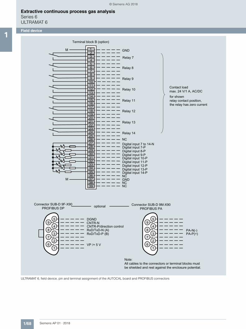
ULTRAMAT 6, field device, pin and terminal assignment
ΩΩ
© Siemens AG 2018
1/68 Siemens AP 01 · 2018
Extractive continuous process gas analysisSeries 6ULTRAMAT 6
Field device1
ULTRAMAT 6, field device, pin and terminal assignment of the AUTOCAL board and PROFIBUS connectors
© Siemens AG 2018
1/69Siemens AP 01 · 2018
Extractive continuous process gas analysisSeries 6
ULTRAMAT 6
Field device1
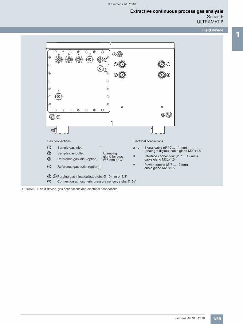
ULTRAMAT 6, field device, gas connections and electrical connections
8
1
2
6
7a b c d
e
53
49
1
2
85
3
-
4
a - c
d
e
9
Interface connection: (Ø 7 ... 12 mm)cable gland M20x1.5
Sample gas inlet
Sample gas outlet
Reference gas inlet (option)
Reference gas outlet (option)
Purging gas inlets/outlets, stubs Ø 10 mm or 3/8"
Clampinggland for pipeØ 6 mm or ¼"
Signal cable (Ø 10 ... 14 mm)(analog + digital): cable gland M20x1.5
Gas connections Electrical connections
Power supply: (Ø 7 ... 12 mm)cable gland M20x1.5
Connection atmospheric pressure sensor, stubs Ø ¼"
© Siemens AG 2018

1/70 Siemens AP 01 · 2018
Extractive continuous process gas analysisSeries 6ULTRAMAT 6
Documentation, suggestions for spare parts1
■ Selection and ordering data
■ More information
The complete documentation is available in various languages for downloading free of charge:http://www.siemens.com/processanalytics/documentation
■ Selection and ordering data
If the ULTRAMAT 6 is supplied with a specially cleaned gas path for high oxygen content ("Cleaned for O2 service"), please ensure that you specify this when ordering spare parts. This is the only way to guarantee that the gas path will continue to comply with the special requirements for this version.
Operating instructions Article No.
ULTRAMAT 6 / OXYMAT 6Gas analyzer for IR-absorbing gases and oxygen
• German C79000-G5200-C143
• English C79000-G5276-C143
• French C79000-G5277-C143
• Spanish C79000-G5278-C143
• Italian C79000-G5272-C143
Description
7MB
-212
1
7MB
-212
3
7MB
-212
4
7MB
-211
1
7MB
-211
2
7MB
-211
1/2
Ex 2 years
(quantity) 5 years (quantity)
Article No.
Analyzer unit
O-ring for cover (window) x x x x x x 2 4 C79121-Z100-A24
Cover (cell length 20 ... 180 mm) x x x x x x 2 2 C79451-A3462-B151
Cover (cell length 0.2 ... 6 mm) x x x x x x 2 2 C79451-A3462-B152
O-rings, set x x x x x x 1 C79451-A3462-D501
Sample gas path
O-ring (hose clip) x x x 2 4 C71121-Z100-A159
Pressure switch x x x 1 2 C79302-Z1210-A2
Flow indicator x x x 1 2 C79402-Z560-T1
Hose clip x x x x x x 1 C79451-A3478-C9
Heating cartridge (heated unit) x x x 1 W75083-A1004-F120
Electronics
Temperature fuse (heated unit) x x 1 W75054-T1001-A150
Fuse (device fuse) x 1 2 A5E00061505
Temperature controller - electronics, 230 V AC
x x x 1 A5E00118527
Temperature controller - electronics, 115 V AC
x x x 1 A5E00118530
Fan, 24 V DC (heated unit) x x x 1 A5E00302916
Front plate with keyboard x x x 1 1 C79165-A3042-B504
Temperature sensor x x x 1 C79165-A3044-B176
Adapter plate, LCD/keyboard x x x x x 1 1 C79451-A3474-B605
Motherboard, with firmware: see spare parts list
x x x x x x 1
LC display x x x x x 1 1 A5E31474846
Connector filter x x x x x 1 W75041-E5602-K2
Fusible element, T 0.63 A/250 V x x x x x 2 3 W79054-L1010-T630
Fusible element, T 1 A/250 V x x x x x x 2 3 W79054-L1011-T100
Fusible element, T 1.6 A/250 V x x 2 3 W79054-L1011-T160
Fusible element, T 2.5 A/250 V x x x 2 3 W79054-L1011-T250
© Siemens AG 2018