International Journal on Electrical Engineering and Informatics - Volume 10, Number 3, September 2018
Experimental Investigation on Sensorless Starting Capability of
New 9-Slot 8-Pole PM BLDC Motor
Alfi Satria, Tri Desmana Rachmildha, Agus Purwadi, and Yanuarsyah Haroen
School of Electrical Engineering and Informatics
Institut Teknologi Bandung
INDONESIA
Abstract: The capability of new 9-slot 8-pole permanent magnet BLDC motor to start without
position sensor is investigated in this paper. The permanent magnet rotor influences the stator
windings inductance as the rotor position changes. It leads to variation of motor current.
Sensorless control of BLDC motor usually uses back EMF method, but this method cannot
be used from standstill, since there is no back EMF. To start this motor smoothly from
standstill, the rotor position can be estimated using inductance variation method by injecting
high frequency low current to the stator windings. The new 9-slot 8-pole PM BLDC motor
has the advantage of its asymmetrical windings. It generates unique current responses when
injected by sinusoidal high frequency current on different rotor positions. The current
responses then can be separated by fuzzy logic algorithm to determine the rotor position. The
experimental results of the estimated rotor position sector with the experimental system are
shown in this paper. From these results, the sensorless starting using inductance variation
method is applicable to the 9-slot 8-pole motor.
Keywords: BLDC motor, 9-slot 8-pole, permanent magnet, asymmetrical winding, sensorless
starting, inductance variation
1. Introduction
To maintain the optimal torque angle of permanent magnet (PM) brushless DC (BLDC)
motor, the driving voltage must be applied to the appropriate phases at any instant. This process
is called commutation. It is decided by the rotor position using additional position sensors.
However, in some applications these sensors, connectors, and wiring increase motor costs and
decrease the motor reliability, so the elimination of this sensors is very desirable [1]. There have
been numerous published methods to eliminate the position sensors. Most of the methods are
based on tracking BEMF [2] [3] [4]. But this BEMF sensing method cannot be used at zero or
low speed because there is no BEMF or it’s very small to detect. To overcome this problem, the
open-loop start-up algorithm is applied [5], high current is flown to force the rotor to move to
the known rotor position, and the voltage is increased smoothly by maintaining V/f comparison.
The disadvantages of this algorithm are slow starting and possibility of initial backward rotation.
Another algorithm used in PM BLDC motor application is inductive sense start-up algorithm
[6]. This algorithm utilizes the inductance variation due to rotor position changes. The stator
winding flux linkage will be increased by the flux of permanent magnet when it is aligned with
a rotor pole or will be decreased when it is aligned with another pole. The flux variation will lead
to decreasing or increasing stator winding inductance due to the saturation [7].
The numerous published research on sensorless control using inductance variance method
use motor models with even stator slot-number like 6, 12, or 18 slots; or three phases/slots with
symmetrical winding [8] [9]. The variation of stator windings inductance in these types of motor
appear twice at a time so the second algorithm must be conducted to determine the exact rotor
position [10].
An interesting type of PM BLDC motor is one with fractional ratio of slot to pole number.
The advantages of this type of motor are high power density, high efficiency, and low cogging
Received: May 30th, 2018. Accepted: September 20th, 2018
DOI: 10.15676/ijeei.2018.10.3.1
421
torque, and also short end-windings [11]. The motor with slot and pole numbers differ by one,
i.e., 2p = Ns ± 1, has high torque density as well as flux-linkage per coil because the coil pitch is
approximately equal to the pole pitch. The fractional ratio of slot number to pole number
contributes to low cogging torque and also because it has the large number of the least common
multiple between the number of slots and poles [12]. This type of motor also has unbalanced
distribution of magnetic flux linkage on stator windings due to permanent magnet on the rotor,
so the inductance extreme value appears once at a time. This unique inductance variation value
could be used to estimate position of the rotor by means of inductance method easier than other
motor type.
One type of the fractional BLDC motor that will be investigated in this paper is a PM BLDC
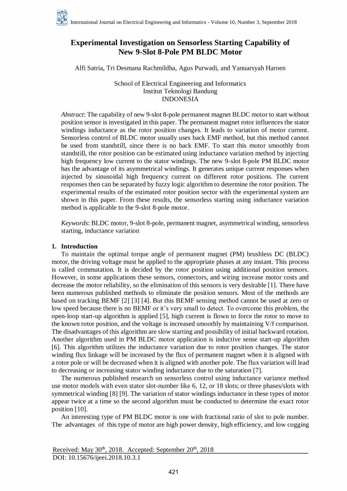
motor with 9-slot and 8-pole number. The motor, that is shown in Figure 1, is developed by ITB
and funded by LPDP for national electric car project. This paper will show the capability of the
motor to be controlled without any position sensor especially at the start from standstill, using
the variation of stator windings inductance due to the rotor position.
Figure 1. PM BLDC Motor with 9-slot/8-pole number (courtesy of ITB and LPDP)
2. Motor Characteristics
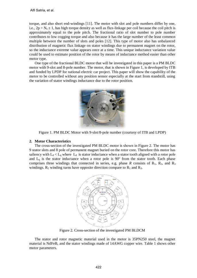
The cross-section of the investigated PM BLDC motor is shown in Figure 2. The motor has
9 stator slots and 8 pole of permanent magnet buried on the rotor core. Therefore this motor has
saliency with Ld < Lq where Ld is stator inductance when a stator tooth aligned with a rotor pole
and Lq is the stator inductance when a rotor pole is 90o from the stator tooth. Each phase
comprises three windings that connected in series, e.g. phase R consists of R1, R2, and R3
windings. R2 winding turns have opposite direction compare to R1 and R3.
Figure 2. Cross-section of the investigated PM BLDCM
The stator and rotor magnetic material used in the motor is 35PN250 steel, the magnet
material is NdFeB, and the stator windings made of 14AWG copper wire. Table 1 shows other
motor parameters.
Alfi Satria, et al.
422

Table 1. Motor parameters
Parameter Value
Number of turns per stator tooth 12
Air gap length, mm 1,5
Magnet thickness, mm 11
Magnet performance, MGOe 30
Torque, Nm 37
Voltage, VDC 240
Current, A 100
Speed, rpm 6,250
Power, kW 25
Because the windings are concentrated and their positions are asymmetrical, the analysis
cannot be simplified using one pair rotor poles. In this paper, all rotor poles should be taken into
account.
3. The Control Principle of 9-Slot/8-Pole PM BLDC Motor
Although the PM BLDC motor is a synchronous electric motor, it has a linear relationship
between current and torque, voltage and rpm, just looks like a DC motor [13]. While the brushed
motors have a mechanical commutation, this brushless motor is electronically controlled.
For one electrical cycle the motor only need the knowledge of six phase-commutation
instants. Only two of the three phase windings are conducting at a time in the excitation of a
three-phase BLDC motor. While the two conducting phases carry excitation voltage and back-
EMF, the no conducting phase only carries the back-EMF. Figure 3 shows the order of PM
BLDC motor commutation to rotate in one direction i.e. counterclockwise (CCW) direction.
Figure 3. BLDC motor six step trapezoidal commutation
When two of three phases are excited e.g. phase R⊕ and S⊝ (step VI of six-step BLDC
commutation), the rotor will rotate to a dead zone and then it will be locked in that position as
shown in Figure 4(a). To maintain the rotation, next step excitation must be applied, that is step
I (R⊕ and T⊝ on Figure 4(b)) and then step II (S⊕ and T⊝ on Figure 4(c)), etc.
Experimental Investigation on Sensorless Starting Capability of New
423
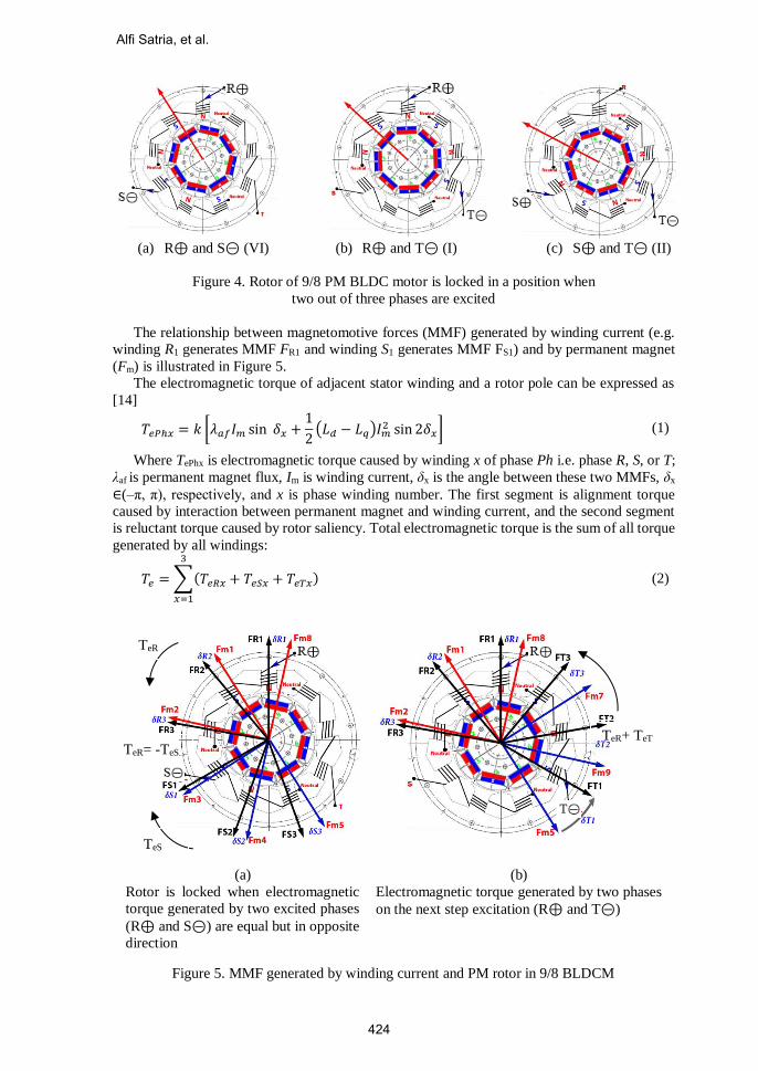
(a) R⊕ and S⊝ (VI) (b) R⊕ and T⊝ (I) (c) S⊕ and T⊝ (II)
Figure 4. Rotor of 9/8 PM BLDC motor is locked in a position when
two out of three phases are excited
The relationship between magnetomotive forces (MMF) generated by winding current (e.g.
winding R1 generates MMF FR1 and winding S1 generates MMF FS1) and by permanent magnet
(Fm) is illustrated in Figure 5.
The electromagnetic torque of adjacent stator winding and a rotor pole can be expressed as
[14]
𝑇𝑒𝑃ℎ𝑥 = 𝑘 [𝜆𝑎𝑓𝐼𝑚 sin 𝛿𝑥 +1
2(𝐿𝑑 − 𝐿𝑞)𝐼𝑚
2 sin 2𝛿𝑥] (1)
Where TePhx is electromagnetic torque caused by winding x of phase Ph i.e. phase R, S, or T;
λaf is permanent magnet flux, Im is winding current, δx is the angle between these two MMFs, δx
∈(–π, π), respectively, and x is phase winding number. The first segment is alignment torque
caused by interaction between permanent magnet and winding current, and the second segment
is reluctant torque caused by rotor saliency. Total electromagnetic torque is the sum of all torque
generated by all windings:
𝑇𝑒 = ∑(𝑇𝑒𝑅𝑥 + 𝑇𝑒𝑆𝑥 + 𝑇𝑒𝑇𝑥)
3
𝑥=1
(2)
(a)
Rotor is locked when electromagnetic
torque generated by two excited phases
(R⊕ and S⊝) are equal but in opposite
direction
(b)
Electromagnetic torque generated by two phases
on the next step excitation (R⊕ and T⊝)
Figure 5. MMF generated by winding current and PM rotor in 9/8 BLDCM
TeR
TeS
TeR= -TeS
TeR+ TeT
Alfi Satria, et al.
424
As an example that is illustrated on Figure 5, at the end of excitation step VI, TeR = - TeS,
electromagnetic torque generated by phase R windings is equal to one generated by phase S
windings but in opposite direction, and the rotor is locked. It is time to do the commutation.
When next step is excited (step I), electromagnetic torque is generated by R and T windings i.e.
Te = TeR + TeT. The rotor will rotate until TeR = - TeT.
Starting 9-Slot/8-Pole PM BLDC Motor
For each electrical cycle, only six rotor position that must be known. Each position displaced
by 60o and handle +30o and -30o position range. The rotor rotating direction is determined by
commutation sequence as shown in Figure 3. The left to the right commutation sequence make
the rotor rotates CCW, and the commutation sequence from the right to the left make the rotor
rotates clockwise. But, what step to conduct first depends on the rotor position. To start 9/8 PM
BLDC motor smoothly, the initial rotor position must be identified in order to generate maximum
torque.
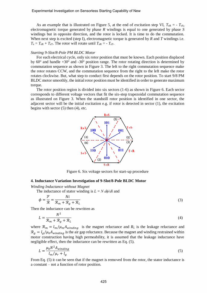
The rotor position region is divided into six sectors (1-6) as shown in Figure 6. Each sector
corresponds to different voltage vectors that fit the six-step trapezoidal commutation sequence
as illustrated on Figure 3. When the standstill rotor position is identified in one sector, the
adjacent sector will be the initial excitation e.g. if rotor is detected in sector (1), the excitation
begins with sector (5) then (4), etc.
Figure 6. Six voltage sectors for start-up procedure
4. Inductance Variation Investigation of 9-Slot/8-Pole BLDC Motor
Winding Inductance without Magnet
The inductance of stator winding is L = N dϕ/di and
𝜙 =ℱ
ℛ=
𝑁𝑖
ℛ𝑚 + ℛ𝑔 + ℛ𝐿 (3)
Then the inductance can be rewritten as
𝐿 =𝑁2
ℛ𝑚 + ℛ𝑔 + ℛ𝐿 (4)
where ℛ𝑚 = 𝑙𝑚/𝜇𝑚𝐴𝑤𝑖𝑛𝑑𝑖𝑛𝑔 is the magnet reluctance and RL is the leakage reluctance and
ℛ𝑔 = 𝑙𝑔/𝜇0𝐴𝑤𝑖𝑛𝑑𝑖𝑛𝑔 is the air gap reluctance. Because the magnet and winding restrained within
motor construction having high permeability, it is assumed that the leakage inductance have
negligible effect, then the inductance can be rewritten as Eq. (5).
𝐿 =𝜇0𝑁2𝐴𝑤𝑖𝑛𝑑𝑖𝑛𝑔
𝑙𝑚 𝜇𝑟⁄ + 𝑙𝑔 (5)
From Eq. (5) it can be seen that if the magnet is removed from the rotor, the stator inductance is
a constant – not a function of rotor position.
Experimental Investigation on Sensorless Starting Capability of New
425
Winding Inductance with Magnet Pole Variation
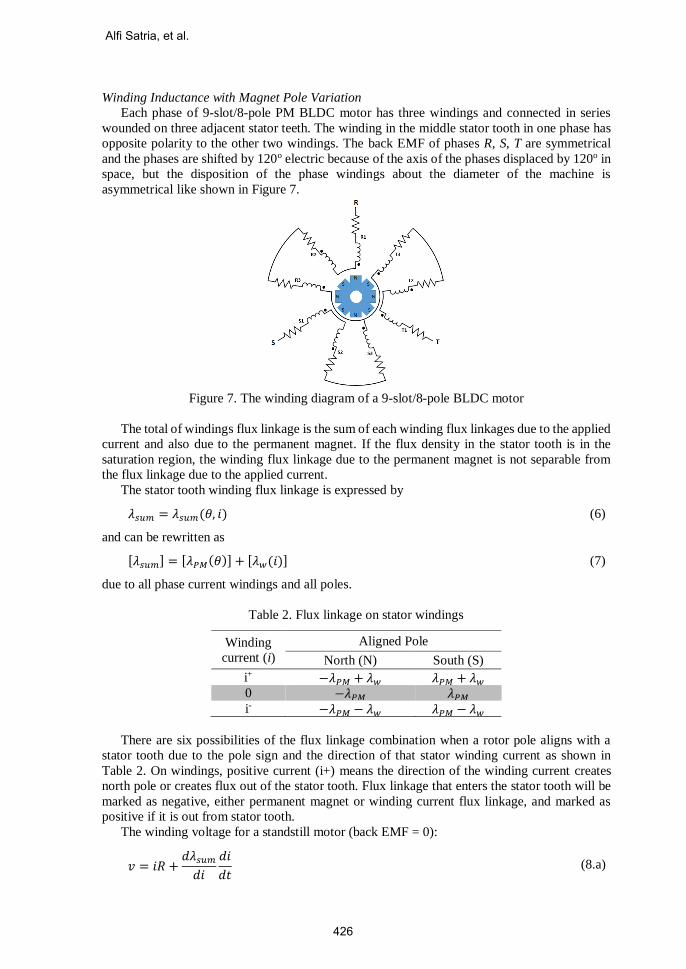
Each phase of 9-slot/8-pole PM BLDC motor has three windings and connected in series
wounded on three adjacent stator teeth. The winding in the middle stator tooth in one phase has
opposite polarity to the other two windings. The back EMF of phases R, S, T are symmetrical
and the phases are shifted by 120o electric because of the axis of the phases displaced by 120o in
space, but the disposition of the phase windings about the diameter of the machine is
asymmetrical like shown in Figure 7.
Figure 7. The winding diagram of a 9-slot/8-pole BLDC motor
The total of windings flux linkage is the sum of each winding flux linkages due to the applied
current and also due to the permanent magnet. If the flux density in the stator tooth is in the
saturation region, the winding flux linkage due to the permanent magnet is not separable from
the flux linkage due to the applied current.
The stator tooth winding flux linkage is expressed by
𝜆𝑠𝑢𝑚 = 𝜆𝑠𝑢𝑚(𝜃, 𝑖) (6)
and can be rewritten as
[𝜆𝑠𝑢𝑚] = [𝜆𝑃𝑀(𝜃)] + [𝜆𝑤(𝑖)] (7)
due to all phase current windings and all poles.
Table 2. Flux linkage on stator windings
Winding
current (i)
Aligned Pole
North (N) South (S)
i+ −𝜆𝑃𝑀 + 𝜆𝑤 𝜆𝑃𝑀 + 𝜆𝑤 0 −𝜆𝑃𝑀 𝜆𝑃𝑀
i- −𝜆𝑃𝑀 − 𝜆𝑤 𝜆𝑃𝑀 − 𝜆𝑤
There are six possibilities of the flux linkage combination when a rotor pole aligns with a
stator tooth due to the pole sign and the direction of that stator winding current as shown in
Table 2. On windings, positive current (i+) means the direction of the winding current creates
north pole or creates flux out of the stator tooth. Flux linkage that enters the stator tooth will be
marked as negative, either permanent magnet or winding current flux linkage, and marked as
positive if it is out from stator tooth.
The winding voltage for a standstill motor (back EMF = 0):
𝑣 = 𝑖𝑅 +𝑑𝜆𝑠𝑢𝑚
𝑑𝑖
𝑑𝑖
𝑑𝑡 (8.a)
Alfi Satria, et al.
426
𝑣 = 𝑖𝑅 + 𝐿𝑑𝑖
𝑑𝑡 (8.b)
dλsum (θ,i) / di is defined as the inductance (L) at the given rotor position and applied current.
Then the winding current can be obtained by integrating Eq. (8.b)
𝑖 =𝑣
𝑅(1 − 𝑒−
𝑅𝐿
𝑡) (9)
When the voltage is applied to the stator winding, the response time of the winding current
is varied depending on the inductance variation caused by the relative position of a rotor.
Phase R winding voltage is determined by:
𝑉𝑅(𝑡) = 𝑉𝑅1(𝑡) + 𝑉𝑅2(𝑡) + 𝑉𝑅3(𝑡) (10.a)
= 𝑖𝑅𝑅𝑡𝑜𝑡 + (𝑑𝜆𝑠𝑢𝑚𝑅1
𝑑𝑖𝑅+
𝑑𝜆𝑠𝑢𝑚𝑅2
𝑑𝑖𝑅+
𝑑𝜆𝑠𝑢𝑚𝑅3
𝑑𝑖𝑅)
𝑑𝑖𝑅
𝑑𝑡 (10.b)
= 𝑖𝑅𝑅𝑡𝑜𝑡 + 𝐿𝑡𝑜𝑡
𝑑𝑖𝑅
𝑑𝑡 (10.c)
where Ltot = LR1 + LR2 + LR3.
Because of the motor geometry, as mention above, each phase windings group will be
influenced at least by three rotor poles, and only one rotor pole that will be aligned with the stator
tooth at a time [15] .
Move the Rotor to Next Sector (Sector = Sector +1)
Injection of High Frequency Low Current
Save Current Response of Phase R
I < Sector < VII ?
Sector = 0
END
Rotor Position Lookup Table
Fuzzification
START
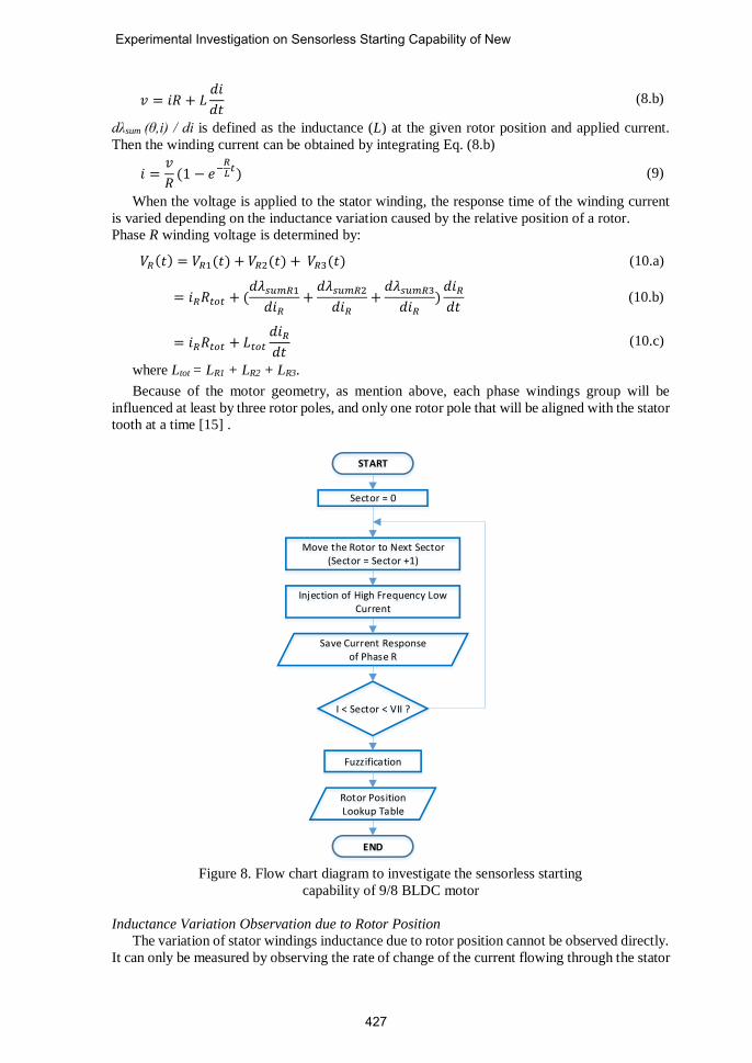
Figure 8. Flow chart diagram to investigate the sensorless starting
capability of 9/8 BLDC motor
Inductance Variation Observation due to Rotor Position
The variation of stator windings inductance due to rotor position cannot be observed directly.
It can only be measured by observing the rate of change of the current flowing through the stator
Experimental Investigation on Sensorless Starting Capability of New
427
winding. In order to get the specific inductance characteristics for each sector of the rotor
position, the motor is injected with high frequency low current when the rotor is fixed at
standstill. High frequency voltage low current injected to the motor does not generate enough
electromagnetic torque to overcome the rotor inertia so the rotor will remain in its initial position.
Fixed rotor position on each sector is obtained by exciting the two phase of the motor as in
Figure-5. After the rotor is locked to certain sector, the motor is injected with high frequency
voltage low current. Current response due to the injected high frequency voltage is observed by
a hall effect current sensor in phase R of the motor. After the response is saved for fuzzification
[16], the rotor is rotated to the next sector. The procedure is repeated for each sector. The flow
chart of this procedure is shown in Figure 8.
For comparison, beside the injection of the proposed sinusoidal high frequency voltage, the
investigation is carried out by injecting trapezoidal high frequency voltage low current in BLDC
trapezoidal commutation sequential order.
5. Experimental Verification, Results and Discussion
Experimental Setup
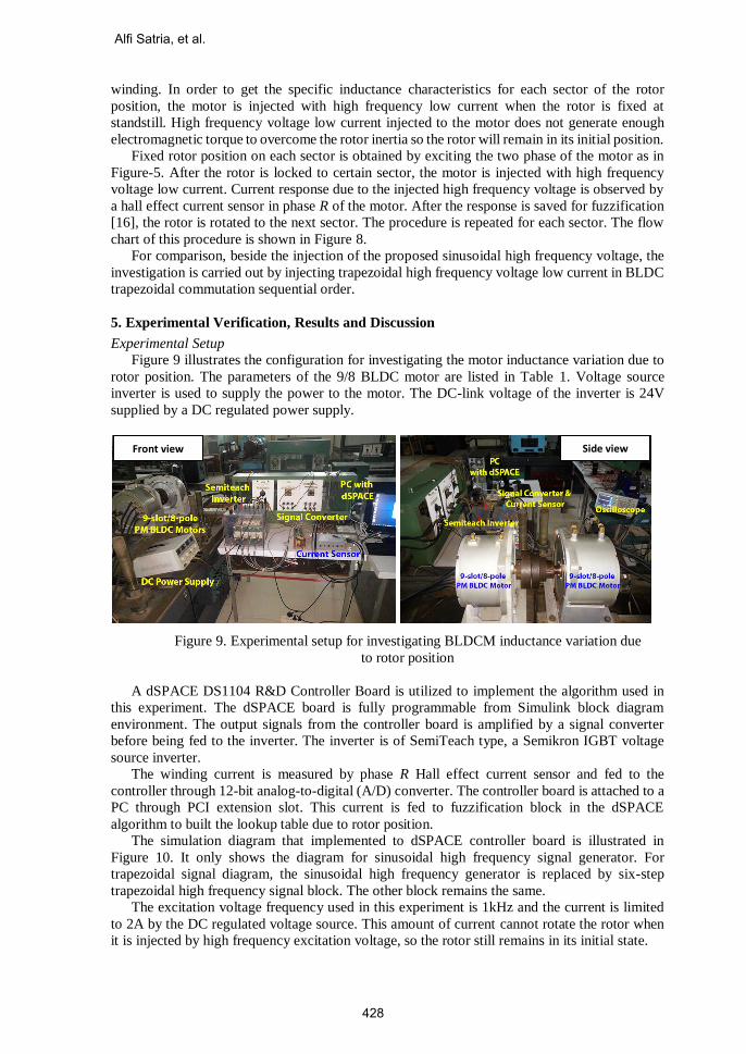
Figure 9 illustrates the configuration for investigating the motor inductance variation due to
rotor position. The parameters of the 9/8 BLDC motor are listed in Table 1. Voltage source
inverter is used to supply the power to the motor. The DC-link voltage of the inverter is 24V
supplied by a DC regulated power supply.
Figure 9. Experimental setup for investigating BLDCM inductance variation due
to rotor position
A dSPACE DS1104 R&D Controller Board is utilized to implement the algorithm used in
this experiment. The dSPACE board is fully programmable from Simulink block diagram
environment. The output signals from the controller board is amplified by a signal converter
before being fed to the inverter. The inverter is of SemiTeach type, a Semikron IGBT voltage
source inverter.
The winding current is measured by phase R Hall effect current sensor and fed to the
controller through 12-bit analog-to-digital (A/D) converter. The controller board is attached to a
PC through PCI extension slot. This current is fed to fuzzification block in the dSPACE
algorithm to built the lookup table due to rotor position.
The simulation diagram that implemented to dSPACE controller board is illustrated in
Figure 10. It only shows the diagram for sinusoidal high frequency signal generator. For
trapezoidal signal diagram, the sinusoidal high frequency generator is replaced by six-step
trapezoidal high frequency signal block. The other block remains the same.
The excitation voltage frequency used in this experiment is 1kHz and the current is limited
to 2A by the DC regulated voltage source. This amount of current cannot rotate the rotor when
it is injected by high frequency excitation voltage, so the rotor still remains in its initial state.
Front view Side view
Alfi Satria, et al.
428
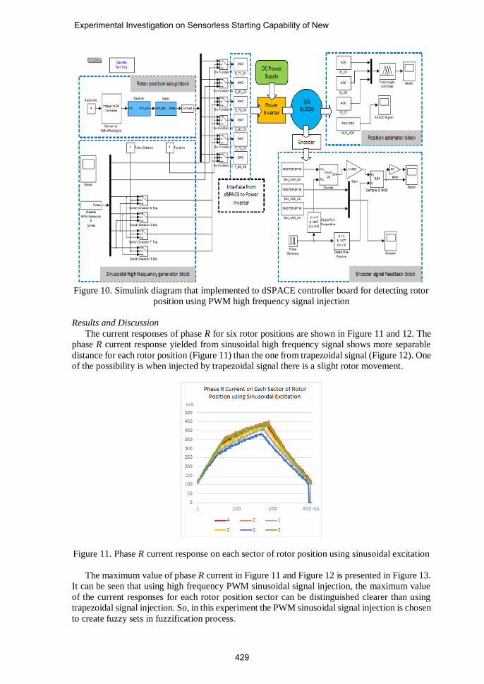
Figure 10. Simulink diagram that implemented to dSPACE controller board for detecting rotor
position using PWM high frequency signal injection
Results and Discussion
The current responses of phase R for six rotor positions are shown in Figure 11 and 12. The
phase R current response yielded from sinusoidal high frequency signal shows more separable
distance for each rotor position (Figure 11) than the one from trapezoidal signal (Figure 12). One
of the possibility is when injected by trapezoidal signal there is a slight rotor movement.
Figure 11. Phase R current response on each sector of rotor position using sinusoidal excitation
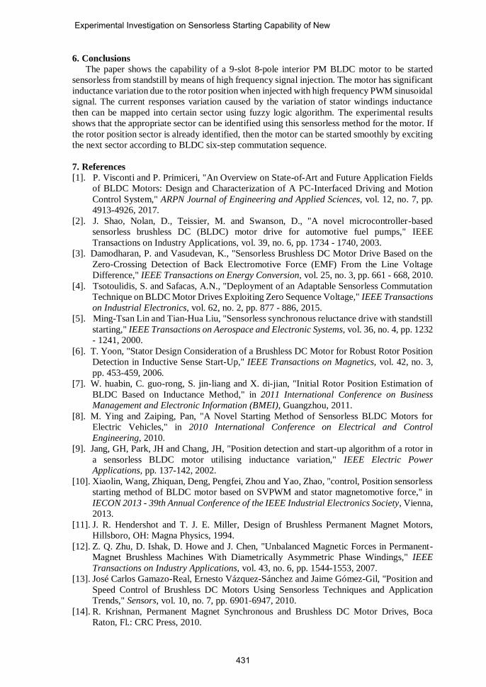
The maximum value of phase R current in Figure 11 and Figure 12 is presented in Figure 13.
It can be seen that using high frequency PWM sinusoidal signal injection, the maximum value
of the current responses for each rotor position sector can be distinguished clearer than using
trapezoidal signal injection. So, in this experiment the PWM sinusoidal signal injection is chosen
to create fuzzy sets in fuzzification process.
Experimental Investigation on Sensorless Starting Capability of New
429
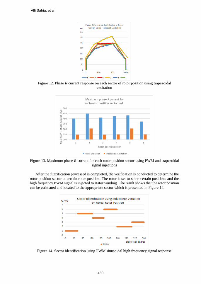
Figure 12. Phase R current response on each sector of rotor position using trapezoidal
excitation
200
250
300
350
400
450
500
1 2 3 4 5 6Ma
xim
um
R p
ha
se c
urr
ent
[mA
]
Rotor position sector
Maximum phase R current for each rotor position sector [mA]
PWM Excitation Trapezoidal Excitation
Figure 13. Maximum phase R current for each rotor position sector using PWM and trapezoidal
signal injections
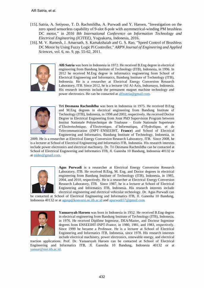
After the fuzzification processed is completed, the verification is conducted to determine the
rotor position sector at certain rotor position. The rotor is set to some certain positions and the
high frequency PWM signal is injected to stator winding. The result shows that the rotor position
can be estimated and located to the appropriate sector which is presented in Figure 14.
Figure 14. Sector identification using PWM sinusoidal high frequency signal response
Alfi Satria, et al.
430
6. Conclusions
The paper shows the capability of a 9-slot 8-pole interior PM BLDC motor to be started
sensorless from standstill by means of high frequency signal injection. The motor has significant
inductance variation due to the rotor position when injected with high frequency PWM sinusoidal
signal. The current responses variation caused by the variation of stator windings inductance
then can be mapped into certain sector using fuzzy logic algorithm. The experimental results
shows that the appropriate sector can be identified using this sensorless method for the motor. If
the rotor position sector is already identified, then the motor can be started smoothly by exciting
the next sector according to BLDC six-step commutation sequence.
7. References
[1]. P. Visconti and P. Primiceri, "An Overview on State-of-Art and Future Application Fields
of BLDC Motors: Design and Characterization of A PC-Interfaced Driving and Motion
Control System," ARPN Journal of Engineering and Applied Sciences, vol. 12, no. 7, pp.
4913-4926, 2017.
[2]. J. Shao, Nolan, D., Teissier, M. and Swanson, D., "A novel microcontroller-based
sensorless brushless DC (BLDC) motor drive for automotive fuel pumps," IEEE
Transactions on Industry Applications, vol. 39, no. 6, pp. 1734 - 1740, 2003.
[3]. Damodharan, P. and Vasudevan, K., "Sensorless Brushless DC Motor Drive Based on the
Zero-Crossing Detection of Back Electromotive Force (EMF) From the Line Voltage
Difference," IEEE Transactions on Energy Conversion, vol. 25, no. 3, pp. 661 - 668, 2010.
[4]. Tsotoulidis, S. and Safacas, A.N., "Deployment of an Adaptable Sensorless Commutation
Technique on BLDC Motor Drives Exploiting Zero Sequence Voltage," IEEE Transactions
on Industrial Electronics, vol. 62, no. 2, pp. 877 - 886, 2015.
[5]. Ming-Tsan Lin and Tian-Hua Liu, "Sensorless synchronous reluctance drive with standstill
starting," IEEE Transactions on Aerospace and Electronic Systems, vol. 36, no. 4, pp. 1232
- 1241, 2000.
[6]. T. Yoon, "Stator Design Consideration of a Brushless DC Motor for Robust Rotor Position
Detection in Inductive Sense Start-Up," IEEE Transactions on Magnetics, vol. 42, no. 3,
pp. 453-459, 2006.
[7]. W. huabin, C. guo-rong, S. jin-liang and X. di-jian, "Initial Rotor Position Estimation of
BLDC Based on Inductance Method," in 2011 International Conference on Business
Management and Electronic Information (BMEI), Guangzhou, 2011.
[8]. M. Ying and Zaiping, Pan, "A Novel Starting Method of Sensorless BLDC Motors for
Electric Vehicles," in 2010 International Conference on Electrical and Control
Engineering, 2010.
[9]. Jang, GH, Park, JH and Chang, JH, "Position detection and start-up algorithm of a rotor in
a sensorless BLDC motor utilising inductance variation," IEEE Electric Power
Applications, pp. 137-142, 2002.
[10]. Xiaolin, Wang, Zhiquan, Deng, Pengfei, Zhou and Yao, Zhao, "control, Position sensorless
starting method of BLDC motor based on SVPWM and stator magnetomotive force," in
IECON 2013 - 39th Annual Conference of the IEEE Industrial Electronics Society, Vienna,
2013.
[11]. J. R. Hendershot and T. J. E. Miller, Design of Brushless Permanent Magnet Motors,
Hillsboro, OH: Magna Physics, 1994.
[12]. Z. Q. Zhu, D. Ishak, D. Howe and J. Chen, "Unbalanced Magnetic Forces in Permanent-
Magnet Brushless Machines With Diametrically Asymmetric Phase Windings," IEEE
Transactions on Industry Applications, vol. 43, no. 6, pp. 1544-1553, 2007.
[13]. José Carlos Gamazo-Real, Ernesto Vázquez-Sánchez and Jaime Gómez-Gil, "Position and
Speed Control of Brushless DC Motors Using Sensorless Techniques and Application
Trends," Sensors, vol. 10, no. 7, pp. 6901-6947, 2010.
[14]. R. Krishnan, Permanent Magnet Synchronous and Brushless DC Motor Drives, Boca
Raton, Fl.: CRC Press, 2010.
Experimental Investigation on Sensorless Starting Capability of New
431
[15]. Satria, A. Setiyoso, T. D. Rachmildha, A. Purwadi and Y. Haroen, "Investigation on the
zero speed sensorless capability of 9-slot 8-pole with asymmetrical-winding PM brushless
DC motor," in 2016 8th International Conference on Information Technology and
Electrical Engineering (ICITEE), Yogyakarta, Indonesia, 2016.
[16]. M. V. Ramesh, J. Amarnath, S. Kamakshaiah and G. S. Rao, "Speed Control of Brushless
DC Motor by Using Fuzzy Logic Pi Controller," ARPN Journal of Engineering and Applied
Sciences, vol. 6, no. 9, pp. 55-62, 2011.
Alfi Satria was born in Indonesia in 1972. He received B.Eng degree in electrical engineering from Bandung Institute of Technology (ITB), Indonesia, in 1996. In
2012 he received M.Eng degree in informatics engineering from School of
Electrical Engineering and Informatics, Bandung Institute of Technology (ITB),
Indonesia. He is a researcher at Electrical Energy Conversion Research
Laboratory, ITB. Since 2012, he is a lecturer IAI Al-Azis, Indramayu, Indonesia.
His research interests include the permanent magnet machine technology and
power electronics. He can be contacted at [email protected].
Tri Desmana Rachmildha was born in Indonesia in 1975. He received B.Eng
and M.Eng degrees in electrical engineering from Bandung Institute of
Technology (ITB), Indonesia, in 1998 and 2002, respectively. He received Doctor Degree in Electrical Engineering from Joint PhD Supervision Program between
Institut Nationale Polytechnique de Toulouse – Ecole Nationale Superieure
d’Electrotechnique, d’Electronique, d’Informatique, d’Hydrolique, et de
Telecommunication (INPT–ENSEEIHT, France) and School of Electrical Engineering and Informatics, Bandung Institute of Technology, Indonesia, in
2009. He is a researcher at Electrical Energy Conversion Research Laboratory, ITB. Since 2008, he
is a lecturer at School of Electrical Engineering and Informatics ITB, Indonesia. His research interests
include power electronics and electrical machinery. Dr. Tri Desmana Rachmildha can be contacted at School of Electrical Engineering and Informatics ITB, Jl. Ganesha 10 Bandung, Indonesia 40132 or
Agus Purwadi is a researcher at Electrical Energy Conversion Research
Laboratory, ITB. He received B.Eng, M. Eng, and Doctor degrees in electrical
engineering from Bandung Institute of Technology (ITB), Indonesia, in 1985,
2004, and 2010, respectively. He is a researcher at Electrical Energy Conversion Research Laboratory, ITB. Since 1987, he is a lecturer at School of Electrical
Engineering and Informatics ITB, Indonesia. His research interests include
electrical engineering and electrical vehicular technology. Dr. Agus Purwadi can
be contacted at School of Electrical Engineering and Informatics ITB, Jl. Ganesha 10 Bandung, Indonesia 40132 or at [email protected] and [email protected].
Yanuarsyah Haroen was born in Indonesia in 1952. He received B.Eng degree in electrical engineering from Bandung Institute of Technology (ITB), Indonesia,
in 1976. He received Diplôme Ingenieur, DEA/Master, and Docteur Ingenieur
degrees from ENSEEIHT-INPT-France, in 1980, 1981, and 1983, respectively.
Since 1999 he became a Professor. He is a lecturer at School of Electrical Engineering and Informatics ITB, Indonesia, since 1978. His research interests
include electrical machinery, power electronics, renewable energy, and electrical
traction applications. Prof. Dr. Yanuarsyah Haroen can be contacted at School of Electrical
Engineering and Informatics ITB, Jl. Ganesha 10 Bandung, Indonesia 40132 or at [email protected].
Alfi Satria, et al.
432