Technical Helpline UK: 0800 731 4924Technical Helpline ROI: 1 800 882 388
Epcon C8 Stainless Steel 1/4
Threaded part M8 M10 M12 M16 M20 M24 M30 fuk (N/mm2) Min. tensile strength 700 700 700 700 700 700 500 fyk (N/mm2) Yield strength 450 450 450 450 450 450 210 As (mm2) Stressed cross-section 36.6 58 84.3 157 227 326.9 522.8 Wel (mm3) Elastic section modulus 31.2 62.3 109.2 277.5 482.4 833.7 1686.0 M0
Rk,s (Nm) Characteristic bending moment 22 45 78 200 301 520 1052 M (Nm) Recommended bending moment 9.0 18.4 31.8 81.6 122.9 212.2 429.4
Anchor mechanical properties
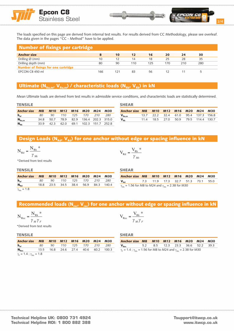
Temperature of the fixing (°C)
Effe
ct o
f te
mpe
ratu
re
on t
he r
esis
tanc
e
Ambient temperature (°C) SPIT EPCON C8 resin Max. time for Waiting time Curing time (h) installation (min.) for 45% load (h) 40°C 5 3 630°C 8 5 820°C 14 6 1210°C 20 12 235°C 26 15 26
Setting time
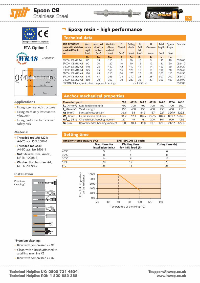
¬ Epoxy resin - high performance
Technical data SPIT EPCON C8 Max. Max. thick Min thick Ø Drilling Ø Ø Total Tighten Eurocode resin with stainless anchor of part to of base Thread depth Drill Clearance length torque steel MAXIMA depth be fixed material bit rod (mm) (mm) (mm) (mm) (mm) (mm) (mm) (mm) (Nm) hef tfix hmin d hO dO df L Tinst
EPCON C8 M8 A4 80 15 110 8 80 10 9 110 10 052400 EPCON C8 M10 A4 90 20 120 10 90 12 12 130 20 052410 EPCON C8 M12 A4 110 25 140 12 110 14 14 160 30 052420 EPCON C8 M16 A4 125 35 160 16 125 18 18 190 60 052440 EPCON C8 M20 A4 170 65 220 20 170 25 22 260 120 052450 EPCON C8 M24 A4 210 63 265 24 210 28 26 300 200 052470 EPCON C8 M30 A4 280 70 350 30 280 35 33 380 400 052490 EPCON C8 Epoxy resin, dual component cartridge - vol. 450 ml 050085
Applications
¬ Fixing steel framed structures
¬ Fixing machinery (resistant to vibration)
¬ Fixing protective barriers and safety rails
Material
¬ Threaded rod M8-M24: A4-70 acc. ISO 3506-1
¬ Threaded rod M30: A4-50 acc. Iso 3506-1
¬ Nut: Stainless steel A4-80, NF EN 10088-3
¬ Washer: Stainless steel A4, NF EN 20898-2
Installation
*Premium cleaning:
¬ Blow with compressed air X2
¬ Clean with a brush attached to a drilling machine X2
¬ Blow with compressed air X2
Premium cleaning*
European Technical Approval
ETA Option 1
n° 0901501
Technical Helpline UK: 0800 731 4924Technical Helpline ROI: 1 800 882 388
Epcon C8 Stainless Steel 2/4
SHEAR
Anchor size M8 M10 M12 M16 M20 M24 M30 VRu,m 13.7 22.2 32.4 61.0 95.4 137.3 156.8 VRk 11.4 18.5 27.0 50.9 79.5 114.4 130.7
SHEAR
Anchor size M8 M10 M12 M16 M20 M24 M30
VRd 7.3 11.9 17.3 32.7 51.3 73.1 55.0γMs = 1.56 for M8 to M24 and γMs = 2.38 for M30
SHEAR
Anchor size M8 M10 M12 M16 M20 M24 M30 VRec 5.2 8.5 12.3 23.3 36.6 52.2 39.3γF = 1.4 ; γMs = 1.56 for M8 to M24 and γMs = 2.38 for M30
TENSILE
Anchor size M8 M10 M12 M16 M20 M24 M30 hef 80 90 110 125 170 210 280 NRu,m 34.8 50.7 78.9 82.9 136.4 202.3 315.0 NRk 33.9 42.3 62.0 69.1 102.3 151.7 252.8
TENSILE
Anchor size M8 M10 M12 M16 M20 M24 M30 hef 80 90 110 125 170 210 280 NRd 18.8 23.5 34.5 38.4 56.9 84.3 140.4γMc = 1.8
TENSILE
Anchor size M8 M10 M12 M16 M20 M24 M30 hef 80 90 110 125 170 210 280 NRec 13.5 16.8 24.6 27.4 40.6 60.2 100.3γF = 1.4 ; γMc = 1.8
Ultimate (NRu,m, VRu,m) / characteristic loads (NRk, VRk) in kN
Mean Ultimate loads are derived from test results in admissible service conditions, and characteristic loads are statistically determined.
Design Loads (NRd, VRd) for one anchor without edge or spacing influence in kN
*Derived from test results
*Derived from test results
Recommended loads (Nrec, Vrec) for one anchor without edge or spacing influence in kN
N NRd
Rk=*
γ McV V
RdRk=
*γ Ms
N NRec
Rk=*
γ γM F
V VRec
Rk=*
.γ γM F
Anchor size 8 10 12 16 20 24 30 Drilling Ø (mm) 10 12 14 18 25 28 35 Drilling depth (mm) 80 90 110 125 170 210 280 Number of fixings for one cartridge EPCON C8 450 ml 166 121 83 56 12 11 5
Number of fixings per cartridge
The loads specified on this page are derived from internal test results. For results derived from CC Methodology, please see overleaf.The data given in the pages “CC - Method” have to be applied.

Technical Helpline UK: 0800 731 4924Technical Helpline ROI: 1 800 882 388
Epcon C8 Stainless Steel 3/4
NRd,s Design steel tensile resistance Anchor size M8 M10 M12 M16 M20 M24 M30
SPIT MAXIMA rod 12.3 19.8 28.9 54.5 85.0 122.5 91.3
MAXIMA rod: γMs = 1.87 for M8 to M24 and γMs = 2.86 for M30
¬ Steel resistance
¬ Steel resistance
(1) The concrete in the area of the anchorage is water saturated.
TENSILE in kN SHEAR in kN
N0Rd,c Design cone resistance
Anchor size M8 M10 M12 M16 M20 M24 M30
hef 80 90 110 125 170 210 280
-40°C to +40°C 13.9 19.4 27.8 33.3 52.8 63.9 94.4
-40°C to +80°C 8.9 13.9 19.4 22.2 33.3 52.8 63.9γMc = 1.8
¬ Concrete cone resistance for dry and wet concrete (1)
¬ Pull-out resistance for dry and wet concrete (1)
N0Rd,p Design pull-out resistance
Anchor size M8 M10 M12 M16 M20 M24 M30
hef 80 90 110 125 170 210 280
-40°C to +40°C 13.9 19.4 27.8 33.3 52.8 63.9 94.4
-40°C to +80°C 8.9 13.9 19.4 22.2 33.3 52.8 63.9γMc = 1.8
¬ Concrete edge resistance
¬ Pryout failure
N N fRd,p = Rd pO
b, .
N N fRd,c = Rd cO
b s c N, ,. . .Ψ Ψ
V V f fRd,c = −Rd cO
b V S C V, , ,. . .β Ψ
V V fRd,cp = Rd cp b s c N, ,. . .0 Ψ Ψ
SPIT CC - Method
VRd,s Design steel shear resistance Anchor size M8 M10 M12 M16 M20 M24 M30
SPIT MAXIMA rod 7.3 11.9 17.3 32.7 51.3 73.1 55.0
MAXIMA rod: γMs = 1.56 for M8 to M24 and γMs = 2.38 for M30
V0Rd,c Design concrete edge resistance
at minimum edge distance (Cmin) Anchor size M8 M10 M12 M16 M20 M24 M30 hef 80 90 110 125 170 210 280 Cmin 40 45 55 65 85 105 140 Smin 40 45 55 65 85 105 140 V0
Rd,c 2.5 3.3 4.8 6.9 12.1 17.9 31.2 γMc = 1.5
V0Rd,cp Design pryout resistance
Anchor size M8 M10 M12 M16 M20 M24 M30 hef 80 90 110 125 170 210 280 -40°C to +40°C 33.3 46.7 66.7 80.0 126.7 153.3 226.7 -40°C to +80°C 21.3 33.3 46.7 53.3 80.0 126.7 153.3γMcp = 1.5
fB Influence of Concrete
Concrete class fB
C20/25 1 C30/40 1.14 C40/60 1.26 C50/60 1.34
NRd = min(NRd,p ; NRd,c ; NRd,s)βN = NSd / NRd ≤ 1
VRd = min(VRd,c ; VRd,cp ; VRd,s)βV = VSd / VRd ≤ 1
βN + βV ≤ 1.2
fβ,V Influence of Shear Loading Direction
Angle β [°] fβ,V
0 to 55 1 60 1.1 70 1.2 80 1.5 90 to 180 2
Technical Helpline UK: 0800 731 4924Technical Helpline ROI: 1 800 882 388
Epcon C8 Stainless Steel 4/4
SPIT CC - Method
SPACINg S Reduction factor Ψs Non-cracked concrete M8 M10 M12 M16 40 0,63 45 0,64 0,63 55 0,67 0,65 0,63 0,61 65 0,70 0,68 0,65 0,63 85 0,77 0,74 0,69 0,67 105 0,83 0,79 0,74 0,71 140 0,94 0,89 0,82 0,78 160 1,00 0,94 0,86 0,82 180 1,00 0,91 0,86 220 1,00 0,94 250 1,00
SPACINg S Reduction factor Ψs Non-cracked concrete M20 M24 M30 85 0,63 105 0,65 0,63 140 0,71 0,67 0,63 160 0,74 0,69 0,64 180 0,76 0,71 0,66 220 0,82 0,76 0,70 250 0,87 0,80 0,72 300 0,94 0,86 0,77 340 1,00 0,90 0,80 370 0,94 0,83 450 1,00 0,90 560 1,00
EDgE C Reduction factor Ψc,N Non-cracked concrete M8 M10 M12 M16 40 0,63 45 0,68 0,63 55 0,77 0,71 0,63 65 0,86 0,79 0,70 0,66 85 1,00 0,95 0,83 0,76 90 1,00 0,86 0,79 110 1,00 0,91 125 1,00
EDgE C Reduction factor Ψc,N Non-cracked concrete M20 M24 M30 85 0,63 105 0,72 0,63 120 0,78 0,68 140 0,87 0,75 0,63 170 1,00 0,86 0,71 210 1,00 0,81 250 0,92 280 1,00
Ψs Influence of spacing for concrete cone resistance in tensile load
Ψc,N Influence of edge for concrete cone resistance in tensile load
Smin < S < Scr,NScr,N = 2.hefΨS must be used for each spacing influenced the anchors group.
Cmin < C < Ccr,NCcr,N = 1.hefΨc,N must be used for each distance influenced the anchors group.
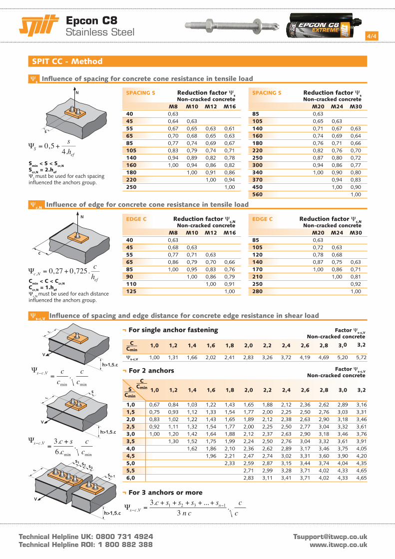
¬ For single anchor fastening
¬ For 2 anchors
¬ For 3 anchors or more
Factor Ψs-c,V Non-cracked concrete
1,0 1,2 1,4 1,6 1,8 2,0 2,2 2,4 2,6 2,8 3,0 3,2
Ψs-c,V 1,00 1,31 1,66 2,02 2,41 2,83 3,26 3,72 4,19 4,69 5,20 5,72
Factor Ψs-c,V Non-cracked concrete
1,0 1,2 1,4 1,6 1,8 2,0 2,2 2,4 2,6 2,8 3,0 3,2
1,0 0,67 0,84 1,03 1,22 1,43 1,65 1,88 2,12 2,36 2,62 2,89 3,16 1,5 0,75 0,93 1,12 1,33 1,54 1,77 2,00 2,25 2,50 2,76 3,03 3,31 2,0 0,83 1,02 1,22 1,43 1,65 1,89 2,12 2,38 2,63 2,90 3,18 3,46 2,5 0,92 1,11 1,32 1,54 1,77 2,00 2,25 2,50 2,77 3,04 3,32 3,61 3,0 1,00 1,20 1,42 1,64 1,88 2,12 2,37 2,63 2,90 3,18 3,46 3,76 3,5 1,30 1,52 1,75 1,99 2,24 2,50 2,76 3,04 3,32 3,61 3,91 4,0 1,62 1,86 2,10 2,36 2,62 2,89 3,17 3,46 3,75 4,05 4,5 1,96 2,21 2,47 2,74 3,02 3,31 3,60 3,90 4,20 5,0 2,33 2,59 2,87 3,15 3,44 3,74 4,04 4,35 5,5 2,71 2,99 3,28 3,71 4,02 4,33 4,65 6,0 2,83 3,11 3,41 3,71 4,02 4,33 4,65
Cmin
C
Cmin
C
Cmin
S
Ψs c V cc
cc
− =,
min min
.
Ψs c V c sc
cc
− =+,
min min
..
.36
Ψs c Vnc s s s s
n cc
c−−=
+ + + + +,
. ... .33
1 2 3 1
Ψs-c,V Influence of spacing and edge distance for concrete edge resistance in shear load