actively controlledsliding guideway
linear ballguideway
brake pad
hydrauliccylinder
piston
guide rail ballscrew
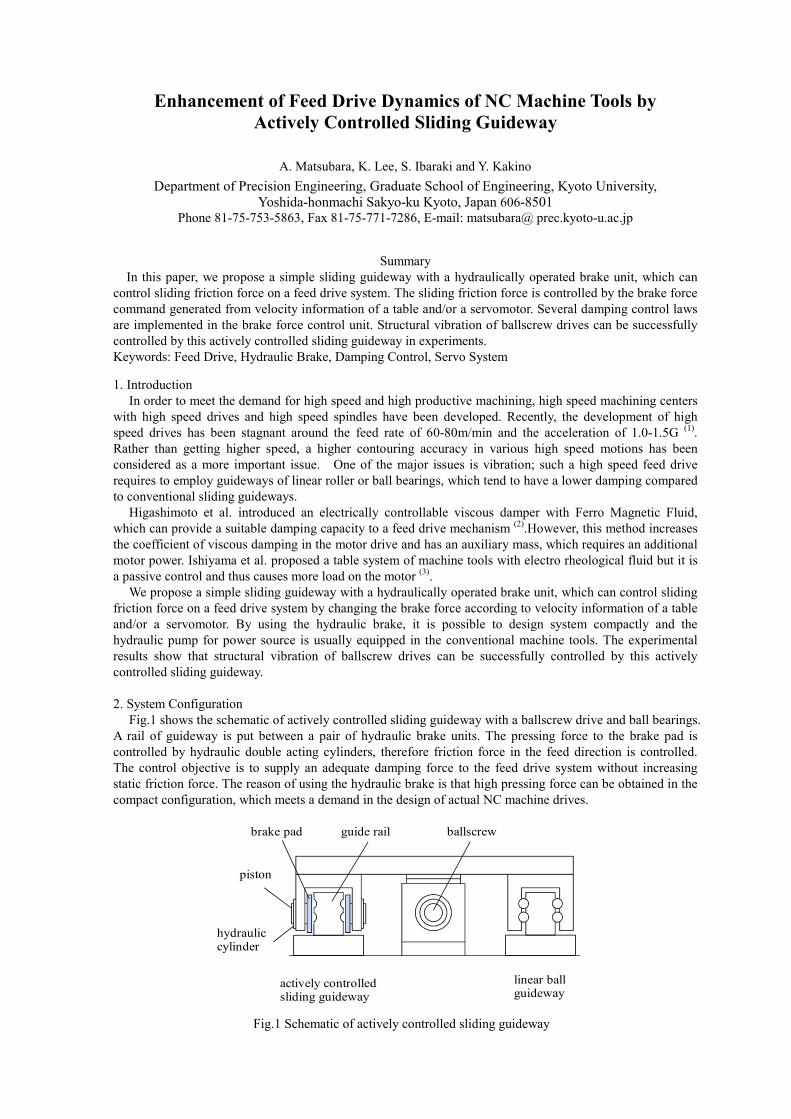
Fig.1 Schematic of actively controlled sliding guideway
Enhancement of Feed Drive Dynamics of NC Machine Tools by Actively Controlled Sliding Guideway
A. Matsubara, K. Lee, S. Ibaraki and Y. Kakino
Department of Precision Engineering, Graduate School of Engineering, Kyoto University, Yoshida-honmachi Sakyo-ku Kyoto, Japan 606-8501
Phone 81-75-753-5863, Fax 81-75-771-7286, E-mail: matsubara@ prec.kyoto-u.ac.jp
Summary In this paper, we propose a simple sliding guideway with a hydraulically operated brake unit, which can
control sliding friction force on a feed drive system. The sliding friction force is controlled by the brake force command generated from velocity information of a table and/or a servomotor. Several damping control laws are implemented in the brake force control unit. Structural vibration of ballscrew drives can be successfully controlled by this actively controlled sliding guideway in experiments. Keywords: Feed Drive, Hydraulic Brake, Damping Control, Servo System
1. Introduction In order to meet the demand for high speed and high productive machining, high speed machining centers
with high speed drives and high speed spindles have been developed. Recently, the development of high speed drives has been stagnant around the feed rate of 60-80m/min and the acceleration of 1.0-1.5G (1). Rather than getting higher speed, a higher contouring accuracy in various high speed motions has been considered as a more important issue. One of the major issues is vibration; such a high speed feed drive requires to employ guideways of linear roller or ball bearings, which tend to have a lower damping compared to conventional sliding guideways.
Higashimoto et al. introduced an electrically controllable viscous damper with Ferro Magnetic Fluid, which can provide a suitable damping capacity to a feed drive mechanism (2).However, this method increases the coefficient of viscous damping in the motor drive and has an auxiliary mass, which requires an additional motor power. Ishiyama et al. proposed a table system of machine tools with electro rheological fluid but it is a passive control and thus causes more load on the motor (3).
We propose a simple sliding guideway with a hydraulically operated brake unit, which can control sliding friction force on a feed drive system by changing the brake force according to velocity information of a table and/or a servomotor. By using the hydraulic brake, it is possible to design system compactly and the hydraulic pump for power source is usually equipped in the conventional machine tools. The experimental results show that structural vibration of ballscrew drives can be successfully controlled by this actively controlled sliding guideway.
2. System Configuration
Fig.1 shows the schematic of actively controlled sliding guideway with a ballscrew drive and ball bearings. A rail of guideway is put between a pair of hydraulic brake units. The pressing force to the brake pad is controlled by hydraulic double acting cylinders, therefore friction force in the feed direction is controlled. The control objective is to supply an adequate damping force to the feed drive system without increasing static friction force. The reason of using the hydraulic brake is that high pressing force can be obtained in the compact configuration, which meets a demand in the design of actual NC machine drives.
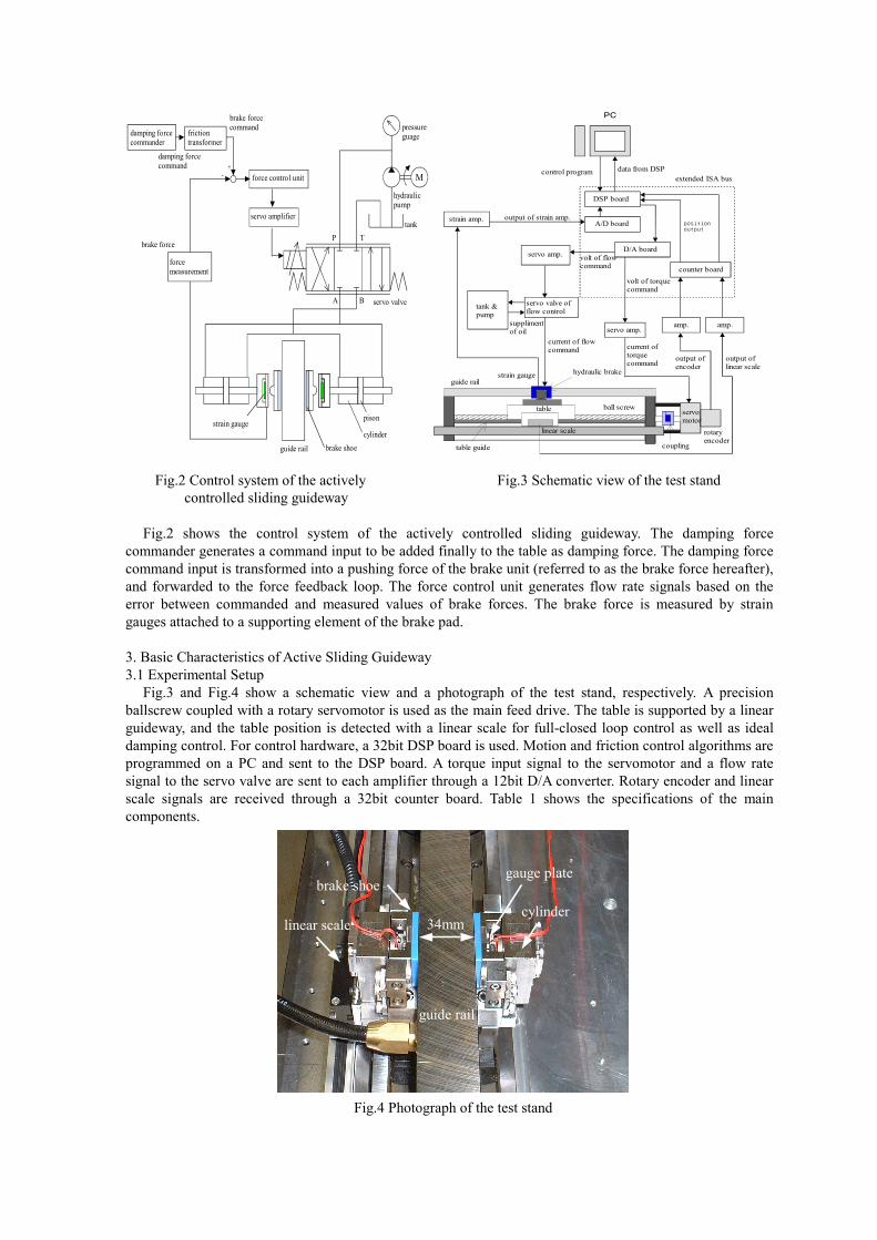
Fig.2 shows the control system of the actively controlled sliding guideway. The damping force commander generates a command input to be added finally to the table as damping force. The damping force command input is transformed into a pushing force of the brake unit (referred to as the brake force hereafter), and forwarded to the force feedback loop. The force control unit generates flow rate signals based on the error between commanded and measured values of brake forces. The brake force is measured by strain gauges attached to a supporting element of the brake pad.
3. Basic Characteristics of Active Sliding Guideway 3.1 Experimental Setup
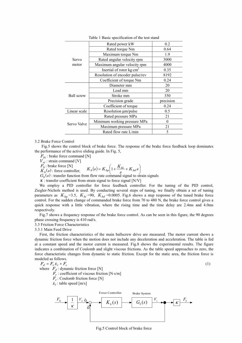
Fig.3 and Fig.4 show a schematic view and a photograph of the test stand, respectively. A precision ballscrew coupled with a rotary servomotor is used as the main feed drive. The table is supported by a linear guideway, and the table position is detected with a linear scale for full-closed loop control as well as ideal damping control. For control hardware, a 32bit DSP board is used. Motion and friction control algorithms are programmed on a PC and sent to the DSP board. A torque input signal to the servomotor and a flow rate signal to the servo valve are sent to each amplifier through a 12bit D/A converter. Rotary encoder and linear scale signals are received through a 32bit counter board. Table 1 shows the specifications of the main components.
Mforce control unit
damping forcecommand
brake forcecommand
servo amplifier
forcemeasurement
hydraulicpump
tank
pressureguage
servo valve
guide rail
pison
cylinderstrain gauge
brake shoe
+-
P T
A B
brake force
frictiontransformer
damping forcecommander
PC
control program data from DSP
counter board
servo amp.amp.
DSP board
D/A board
A/D board
servo amp.
servo valve offlow control
tank & pump
volt of torquecommand
volt of flowcommand
output ofencoder
position output
supplimentof oil
strain amp.
extended ISA bus
output of strain amp.
amp.
output of linear scale
current of torquecommand
servomotor
hydraulic brake
table
rotaryencoder
ball screw
guide rail
linear scale
table guide coupling
strain gauge
current of flowcommand
Fig.2 Control system of the actively Fig.3 Schematic view of the test stand
controlled sliding guideway
Fig.4 Photograph of the test stand
brake shoe
linear scale
guide rail
34mmcylinder
gauge plate
3.2 Brake Force Control Fig.5 shows the control block of brake force. The response of the brake force feedback loop dominates
the performance of the active sliding guide. In Fig. 5, biF : brake force command [N] siV : strain command [V] bF : brake force [N]
)(sK b : force controller, )(sGb : transfer function from flow rate command signal to strain signals
κ : transfer coefficient from strain signal to force signal [N/V] We employ a PID controller for force feedback controller. For the tuning of the PID control,
Ziegler-Nichols method is used. By conducting several steps of tuning, we finally obtain a set of tuning parameters as bpK =3.5, biK =90, bdK =0.0005. Fig.6 shows a step response of the tuned brake force control. For the sudden change of commanded brake force from 70 to 480 N, the brake force control gives a quick response with a little vibration, where the rising time and the time delay are 2.4ms and 4.0ms respectively.
Fig.7 shows a frequency response of the brake force control. As can be seen in this figure, the 90 degrees phase crossing frequency is 410 rad/s. 3.3 Friction Force Characteristics 3.3.1 Main Feed Drive
First, the friction characteristics of the main ballscrew drive are measured. The motor current shows a dynamic friction force when the motion does not include any deceleration and acceleration. The table is fed at a constant speed and the motor current is measured. Fig.8 shows the experimental results. The figure indicates a combination of Coulomb and slight viscous frictions. As the table speed approaches to zero, the force characteristic changes from dynamic to static friction. Except for the static area, the friction force is modeled as follows.
ctvd FxFF += � (1) where dF : dynamic friction force [N] vF : coefficient of viscous friction [N⋅s/m] cF : Coulomb friction force [N] tx� : table speed [m/s]
)(sKb
Force Controller
κ1
Brake System
κ)(sGbbiF siV sV bF+
-
Fig.5 Control block of brake force
( ) ��
���
� ++= sKsKKsK bd
bibpb 1
Table 1 Basic specification of the test stand Rated power kW 0.2 Rated torque Nm 0.64
Maximum torque Nm 1.9 Rated angular velocity rpm 3000
Maximum angular velocity rpm 4000 Inertial of rotor kg⋅cm2 0.35
Resolution of encoder pulse/rev 8192
Servo motor
Coefficient of torque Nm 0.24 Diameter mm 20
Lead mm 20 Stroke mm 350
Precision grade precision Ball screw
Coefficient of torque 0.24 Linear scale Resolution µm/pulse 0.5
Rated pressure MPa 21 Minimum working pressure MPa 0
Maximum pressure MPa 21 Servo Valve
Rated flow rate L/min 5

To identify the static friction force, another experiment is conducted. The torque command for servomotor is gradually increased, and the motor current at the moment when the table is started moving is measured, which is regarded as the static friction force sF . From several experiments, sF is identified as 41 N. 3.3.2 Sliding Guideway
Second, the relationship between the break force and friction increment in a feed direction must be investigated. In this paper, this friction increment is assumed to be a function of table speed and brake force:
( )btd F,xgF �=∆ (2) The same experiments as shown in Section 3.3.1 are conducted, and the friction increment by brake is
estimated by subtracting the motor torque without brake force from the one with a constant brake force at a constant speed.
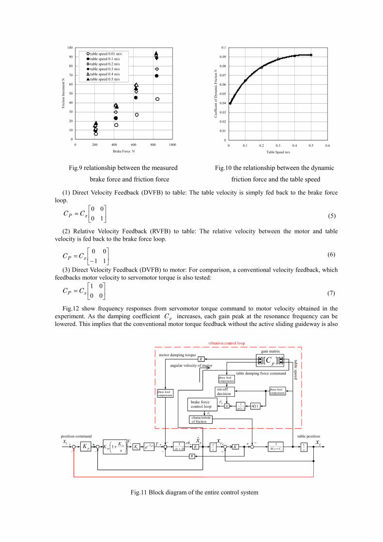
Fig.9 shows the relationship between the measured brake force and friction force. As seen in Fig.9, this relationship can be linearly modeled at each table speed. That is, Eq.(2) can be
written as : btd FxF )( �µ∆ = (3)
where )( tx�µ is the dynamic friction coefficient. By identifying each slope of the linear relationship in Fig.9, the relationship between the dynamic friction
force and the table speed is obtained as shown in Fig.10. This relationship can be modeled as a 4th order polynomial : 03650361099604919850 234 .....)( ++−+= ttttt xxxxx �����µ (4) 4. Experiments of Damping Control
In order to examine the influence of active sliding guideway to the dynamics of main feed drive, damping control is attempted on the test stand. Fig.11 shows the block diagram of the entire control system, which consists of a servo loop for main drive and a damping control block with the active sliding guideway. The main servo loop employs a conventional velocity (PI) and position (P) feedback loops. The damping control block is designed based on velocity feedback control. The motor velocity and table velocity are fed back to the servomotor and the brake force loop of siding guideway with 2x2 gain matrix pC . By selecting pC , various damping control laws can be realized. In this paper, the following velocity feedback laws are attempted.
-50
-40
-30
-20
-10
0
10
20
30
40
50
-0.1 -0.08 -0.06 -0.04 -0.02 0 0.02 0.04 0.06 0.08 0.1
Table velocity m/s
Fric
tion
forc
e N
Fig.8 Control block of pushing force of the brake
0 0.05 0.1 0.15 0.2 0.25 0.30
100
200
300
400
500
600
700
Time s
Bra
ke fo
rce
N
100
101
102
103
-10
-5
0
5
10
Gai
n dB
Frequency rad/s
100
101
102
103
-400
-300
-200
-100
0
100
Phas
e
Frequency rad/s
°
Fig.6 Step response of the tuned brake force control Fig.7 Frequency response of the brake force control
solid: command inputdash dotted: measured
(1) Direct Velocity Feedback (DVFB) to table: The table velocity is simply fed back to the brake force loop.
(5)
(2) Relative Velocity Feedback (RVFB) to table: The relative velocity between the motor and table
velocity is fed back to the brake force loop.
(6)
(3) Direct Velocity Feedback (DVFB) to motor: For comparison, a conventional velocity feedback, which feedbacks motor velocity to servomotor torque is also tested:
(7)
Fig.12 show frequency responses from servomotor torque command to motor velocity obtained in the
experiment. As the damping coefficient zC increases, each gain peak at the resonance frequency can be lowered. This implies that the conventional motor torque feedback without the active sliding guideway is also
0
10
20
30
40
50
60
70
80
90
100
0 200 400 600 800 1000
Brake Force N
Fric
tion
Incr
emen
t N
table speed 0.01 m/stable speed 0.1 m/stable speed 0.2 m/stable speed 0.3 m/stable speed 0.4 m/stable speed 0.5 m/s
0
0.01
0.02
0.03
0.04
0.05
0.06
0.07
0.08
0.09
0.1
0 0.1 0.2 0.3 0.4 0.5 0.6
Table Speed m/s
Coe
ffice
nt o
f Dyn
amic
Fric
tion
N
Fig.9 relationship between the measured Fig.10 the relationship between the dynamic
brake force and friction force friction force and the table speed
DJs +1
Rs1 K
tt CsM +1
s1+
−
+
−
T txmsθ rx
R
][][][ pCR
− −+
angular velocity of motor
table speed
motor damping torque
table damping force command
vibration control loop
gain matrix
phase leadcompensator
× ( )tx�µ1
|AbsbiF
phase leadcompensator
phase leadcompensator
on-offdecision
brake forcecontrol loop
bFcharacteristicof friction
tK sTde−rx�iV
��
���
� +sKK vi
vp 1−
+
position command table position
pK +
−
+ix
Fig.11 Block diagram of the entire control system
��
���
�=
1000
zP CC
��
���
�
−=
1100
zP CC
��
���
�=
0001
zP CC
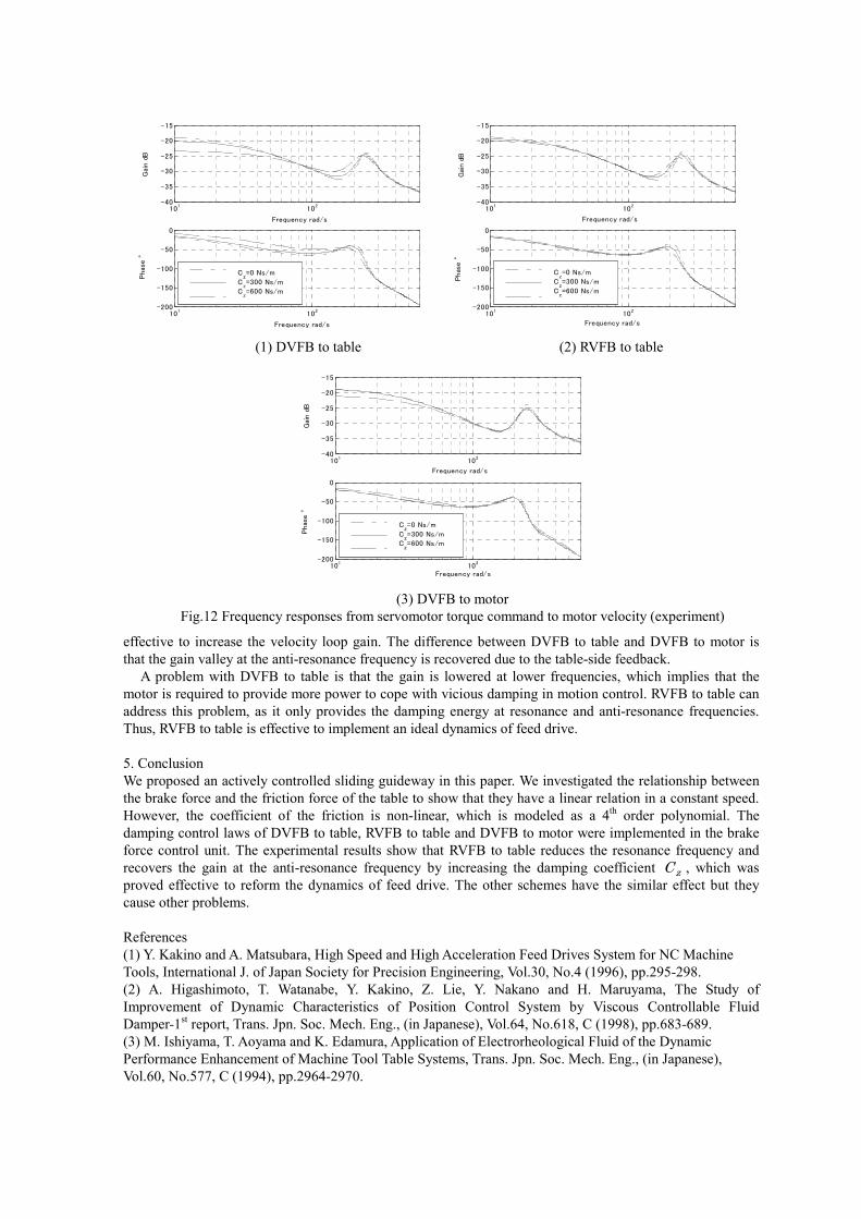
effective to increase the velocity loop gain. The difference between DVFB to table and DVFB to motor is that the gain valley at the anti-resonance frequency is recovered due to the table-side feedback.
A problem with DVFB to table is that the gain is lowered at lower frequencies, which implies that the motor is required to provide more power to cope with vicious damping in motion control. RVFB to table can address this problem, as it only provides the damping energy at resonance and anti-resonance frequencies. Thus, RVFB to table is effective to implement an ideal dynamics of feed drive. 5. Conclusion We proposed an actively controlled sliding guideway in this paper. We investigated the relationship between the brake force and the friction force of the table to show that they have a linear relation in a constant speed. However, the coefficient of the friction is non-linear, which is modeled as a 4th order polynomial. The damping control laws of DVFB to table, RVFB to table and DVFB to motor were implemented in the brake force control unit. The experimental results show that RVFB to table reduces the resonance frequency and recovers the gain at the anti-resonance frequency by increasing the damping coefficient zC , which was proved effective to reform the dynamics of feed drive. The other schemes have the similar effect but they cause other problems. References (1) Y. Kakino and A. Matsubara, High Speed and High Acceleration Feed Drives System for NC Machine Tools, International J. of Japan Society for Precision Engineering, Vol.30, No.4 (1996), pp.295-298. (2) A. Higashimoto, T. Watanabe, Y. Kakino, Z. Lie, Y. Nakano and H. Maruyama, The Study of Improvement of Dynamic Characteristics of Position Control System by Viscous Controllable Fluid Damper-1st report, Trans. Jpn. Soc. Mech. Eng., (in Japanese), Vol.64, No.618, C (1998), pp.683-689. (3) M. Ishiyama, T. Aoyama and K. Edamura, Application of Electrorheological Fluid of the Dynamic Performance Enhancement of Machine Tool Table Systems, Trans. Jpn. Soc. Mech. Eng., (in Japanese), Vol.60, No.577, C (1994), pp.2964-2970.
101
102
-40
-35
-30
-25
-20
-15
Gai
n d
B
Frequency rad/s
101
102
-200
-150
-100
-50
0
Phas
e °
Frequency rad/s
Cz=0 Ns/m
Cz=300 Ns/m
Cz=600 Ns/m
101
102
-40
-35
-30
-25
-20
-15
Gai
n d
B
Frequency rad/s
101
102
-200
-150
-100
-50
0
Phas
e °
Frequency rad/s
Cz=0 Ns/m
Cz=300 Ns/m
Cz=600 Ns/m
(1) DVFB to table (2) RVFB to table
101
102
-40
-35
-30
-25
-20
-15
Gai
n d
B
Frequency rad/s
101
102
-200
-150
-100
-50
0
Phas
e °
Frequency rad/s
Cz=0 Ns/m
Cz=300 Ns/m
Cz=600 Ns/m
(3) DVFB to motor
Fig.12 Frequency responses from servomotor torque command to motor velocity (experiment)