Dynamic Article LinksC<Energy &Environmental Science
Cite this: Energy Environ. Sci., 2012, 5, 7042
www.rsc.org/ees PAPER
Dow
nloa
ded
by I
owa
Stat
e U
nive
rsity
on
02 M
ay 2
012
Publ
ishe
d on
23
Febr
uary
201
2 on
http
://pu
bs.r
sc.o
rg |
doi:1
0.10
39/C
2EE
0347
8FView Online / Journal Homepage / Table of Contents for this issue
Enhanced charge separation in organic photovoltaic films doped withferroelectric dipoles†
Kanwar S. Nalwa,a John A. Carr,a Rakesh C. Mahadevapuram,b Hari K. Kodali,c Sayantan Bose,d
Yuqing Chen,a Jacob W. Petrich,e Baskar Ganapathysubramanianc and Sumit Chaudhary*ab
Received 15th December 2011, Accepted 22nd February 2012
DOI: 10.1039/c2ee03478f
A key requirement for realizing efficient organic photovoltaic (OPV) cells is the dissociation of
photogenerated electron-hole pairs (singlet-excitons) in the donor polymer, and charge-transfer-
excitons at the donor–acceptor interface. However, in modern OPVs, these excitons are typically not
sufficiently harnessed due to their high binding energy. Here, we show that doping the OPV active-
layers with a ferroelectric polymer leads to localized enhancements of electric field, which in turn leads
to more efficient dissociation of singlet-excitons and charge-transfer-excitons. Bulk-heterojunction
OPVs based on poly(3-hexylthiophene):[6,6]-phenyl-C61-butyric acid methyl ester are fabricated.
Upon incorporating a ferroelectric polymer as additive in the active-layer, power conversion efficiencies
increase by nearly 50%, and internal quantum efficiencies approach 100% – indicating complete exciton
dissociation at certain photon energies. Similar enhancements in bilayer-heterojunctions, and direct
influence of ferroelectric poling on device behavior show that improved dissociation is due to
ferroelectric dipoles rather than any morphological change. Enhanced singlet-exciton dissociation is
also revealed by photoluminescence lifetime measurements, and predicted by simulations using
a numerical device model.
aDepartment of Electrical and Computer Engineering, Iowa StateUniversity, Ames, IA, USA. E-mail: [email protected]; Tel: +1 515294 0606bDepartment of Materials Science and Engineering, Iowa State University,Ames, IA, USAcDepartment of Mechanical Engineering, Iowa State University, Ames, IA,USAdAmes Laboratory-USDOE, Iowa State University, Ames, IA, USAeDepartment of Chemistry, Iowa State University, Ames, IA, USA
† Electronic supplementary information (ESI) available: AFM images,simulation methodogy, Raman spectra of photovoltaic films afteraddition of PVDF-TrFE, Ferroelectric poling results for bilayerdevices. See DOI: 10.1039/c2ee03478f
Broader context
Organic photovoltaics are making rapid progress, with their solar-
digits. State-of-the-art organic photovoltaic devices still suffer fro
recombination of photogenerated electron-hole pairs (singlet excito
donor–acceptor interface. In this paper, we present a strategy to m
active layers with small amounts of ferroelectric material. Dipoles
electric field, which in turn lead to more efficient dissociation of s
conversion efficiencies. We believe that in addition to directly impac
for investigating more synergies between ferroelectric and conjugat
conjugated polymers for new paradigms of hybrid piezoelectric, py
multiple sources.
7042 | Energy Environ. Sci., 2012, 5, 7042–7049
Introduction
Organic photovoltaic (OPV) cells with polymer-fullerene bulk-
heterojunction (BHJ) architecture are attracting considerable
interest owing to their promise for low-cost solar-electric
conversion. Recent progress in power conversion efficiencies
of BHJ cells has primarily resulted from the development of
materials with tailored energy levels,1–3 and utilization
of annealing and solvent additives to control nano-
morphology.4–9 BHJ cells have now attained power conversion
efficiencies of 7–8%, which are impressive, albeit, still lower
than the Shockley-Queisser theoretical limit of 21%.10 This
electric power conversion efficiencies now approaching double
m several losses or bottlenecks – a major one of them being
ns) within the donor material, or charge-transfer-excitons at the
itigate this problem – doping the bulk of organic photovoltaic
within the ferroelectric material lead to local enhancements of
inglet and charge transfer excitons, thus improving the power
ting the area of organic solar cells, our study also opens the door
ed organics – for example, fusion of ferroelectric polymers and
roelectric, and photovoltaic devices for energy harvesting from
This journal is ª The Royal Society of Chemistry 2012
Dow
nloa
ded
by I
owa
Stat
e U
nive
rsity
on
02 M
ay 2
012
Publ
ishe
d on
23
Febr
uary
201
2 on
http
://pu
bs.r
sc.o
rg |
doi:1
0.10
39/C
2EE
0347
8F
View Online
performance gap is primarily due to losses incurred by
insufficient light trapping, parasitic absorption in layers other
than the OPV active-layer, singlet-exciton (SE) recombination
due to low exciton diffusion lengths, charge-transfer-exciton
(CTE) recombination, and low carrier mobilities.10 Kirchartz
et al. estimated that among all loss pathways, SE recombination
accounts for nearly 12% efficiency loss, and CTE recombination
(geminate and non-geminate) accounts for more than 32%
efficiency loss.10
In this work, we show that by incorporating ferroelectric
dipoles as additives in OPV active layers, both SEs and CTEs
can be dissociated more efficiently, leading to enhanced power
conversion efficiencies. We used two different OPV structures
(BHJ and bilayer) based on a poly(3-hexylthiophene):[6,6]-
phenyl-C61-butyric acid methyl ester (P3HT:PCBM) material
system to investigate the effect of the ferroelectric co-polymer
additive poly(vinylidenefluoride-co-trifluoroethylene) (PVDF-
TrFE). We show that the addition of ferroelectric dipoles can
significantly improve photovoltaic performance, resulting in
�52% and �60% enhancement of overall power conversion
efficiency for BHJ and bilayer cells, respectively. Ruling out
other mechanisms using optoelectronic and photophysical
characterizations, we show that the performance improvement
is due to exciton dissociation being enhanced by the local
electric field of ferroelectric dipoles. The efficiency of the BHJ
cells improved from 2.5% (for the reference device) to 3.9%
upon incorporating PVDF-TrFE additives. The efficiency of
our reference device is lower than the best P3HT:PCBM cell
efficiencies reported in literature because blend solutions
utilized for device fabrication consisted of a low-boiling-point
solvent tetrahydrofuran (THF) (25% by volume, 75% being
ortho-dicholorbenzene). THF was included because it is
a good solvent for PVDF-TrFE, however it is typically not
preferred in OPVs due to its fast evaporation rate which
leads to suboptimal BHJ morphologies.11 We expect that
exploration of other good or latent solvents of PVDF-TrFE
will lead to even higher efficiencies than achieved in this
study. Nevertheless, our results unambiguously show that
ferroelectric additives (a) lead to improved SE dissociation in
morphologies that are otherwise suboptimal in this regard,
and (b) also reduce CTE recombination, as evident from
internal quantum efficiencies approaching 100% in our BHJ
cells.
Recently, Yaun et al. utilized PVDF-TrFE as a buffer layer
at the interface of the OPV active-layer and Al cathode, and
efficiency enhancement was observed.12 However, Asadi et al.
demonstrated that the performance improvement was insenstive
to ferroelectric polarization direction, and was primarily due to
increase in open-circuit-voltage (Voc) caused by the improvement
of the Al cathode - similar to the effect of alkaline-fluoride buffer
layers at the organic/cathode interfaces.13 In contrast, our report
is the first use of a ferroelectric as a helpful additive within the
bulk of OPV active-layer. In our ferroelectric doped devices,
device performance is clearly influenced by the ferroelectric
polarization direction. Also, the performance improvement in
our devices is not due to increase in Voc or improvement of the
cathode, but rather due to higher short-circuit-current and fill
factor resulting from enhanced SE and CTE dissociation, as
characterized and discussed below.
This journal is ª The Royal Society of Chemistry 2012
Results and discussion
At the outset, we hypothesized that a ferroelectric material
embedded in an OPV active-layer can possibly reduce one or
more of the aforementioned losses. First, the mismatch of host
material’s refractive index and the embedded ferroelectric’s
refractive index can lead to light scattering sites advantageous for
optical absorption.14 Second, the permanent electrical polariza-
tion of ferroelectric dipoles can generate localized enhancements
of electric field within the active-layer, affecting carrier drift or
exciton dissociation or both. According to the modified Braun
model15 (eqn (1)), the probability of ionizing an exciton is
a function of electric field strength (E) and binding energy (EB).
fðEÞ ¼ 1
1þ u0
FðEÞ eEBkT
(1)
where F(E) is a function of e3E/8p303k2T 2. Binding energies of
SE and CTE states have been estimated to be in the range of
0.4–0.7 eV and 0.2–0.3 eV, respectively.16,17 Both energies are
an order of magnitude higher than kT at room temperature
(�0.026 eV), making the exponential term in eqn (1) very large.
SE excitons that are able to reach the donor–acceptor interface,
do indeed decay into a CTE state due to the offset between the
lowest unoccupied molecular orbitals of donors and acceptors.
However, SEs that do not reach the interface, and CTEs them-
selves, are still the loss mechanisms, which can be minimized by
increased ionization enabled by higher E (eqn (1)). This thought
is supported by various studies which show that photocurrent in
BHJ OPVs saturates only under a large (>10 V) external reverse
bias.18,19 This implies that complete exciton fission (i.e. all SEs
and CTEs) requires an internal electric field of �50–70 V mm�1,
which is much higher than the field generated by difference in the
work-functions of electrodes (typically 1–10 V mm�1). Hence, we
expected that ferroelectric dipoles embedded in an OPV active-
layer might help in this regard due to their inherent electric
field.
We chose PVDF-TrFE for our investigations because it is
solution processable, and exhibits a net dipole moment at room
temperature.20 Also, its dielectric constant (n� 11) is higher than
that of organic semiconductors (n � 2), and thus suitable to test
our hypothesis regarding scattering assisted optical absorption.
Further, using the classical dipole-field model,21
E ¼ 4p
3sf (2)
where 3 is the relative permittivity of PVDF-TrFE, s is
the pyroinduced surface charge density (�6 mC cm�2 for
PVDF-TrFE)22 and f is the volume fraction occupied by the
dipoles, we estimated a theoretical enhancement to the device’s
local internal field to be �8*103*f V mm�1. A small volume
fraction of �0.03, for example, corresponds to electric field of
�240 V mm�1, which is expected to sufficiently dissociate SEs
and CTEs.
Four P3HT:PCBM based BHJ cells were fabricated with
different amounts of PVDF-TrFE additive (0%, 5%, 10%, and
20% PVDF-TrFE by weight of P3HT). For appropriate
comparisons, the final concentration of P3HT:PCBM was kept
same (10 mg ml�1) in all four solutions, and each solution had the
Energy Environ. Sci., 2012, 5, 7042–7049 | 7043

Table 1 Effect of PVDF-TrFE concentration on the photovoltaicparameters of BHJ OPVs
Jsc (mA cm�2) Voc (V) FF Efficiency
0% PVDF-TrFE 9.6 0.55 48 2.5%5% PVDF-TrFE 10.4 0.55 54 3.1%10% PVDF-TrFE 11.3 0.57 60 3.9%20% PVDF-TrFE 10.2 0.57 55 3.2%
Dow
nloa
ded
by I
owa
Stat
e U
nive
rsity
on
02 M
ay 2
012
Publ
ishe
d on
23
Febr
uary
201
2 on
http
://pu
bs.r
sc.o
rg |
doi:1
0.10
39/C
2EE
0347
8F
View Online
same ratio of THF (good solvent for PVDF-TrFE) and ortho-
dicholorobenzene (ODCB) (1 : 3). On completing the devices, we
annealed them at 150 �C to improve the crystallinity of P3HT
and PVDF-TrFE. Fig. 1a and Table 1 show the performance of
our devices. We observed that short-circuit-current (Jsc) and fill
factor (FF) increase upon the addition of PVDF-TrFE up to 10%
concentration, while the Voc of all devices was quite similar.
Next, we set out to test our aforementioned hypotheses and
determine the cause(s) behind performance improvement. As
shown in Fig. 1b, performance increased as PVDF-TrFE
concentration increased from 0% to 5% to 10%. But 20%
concentration failed to improve the performance further. We
suspected that this was due to aggregation of PVDF-TrFE
dipoles. Above some threshold concentration of dipoles, inter-
dipole interaction energy increases and leads to aggregation,21
shielding the electrostatic fields of individual dipoles. Supple-
mentary Fig. S1 shows evidence of this aggregation in the form of
PVDF-TrFE agglomerates of size �100–200 nm. Fig. 1c also
shows an indirect evidence in the form of increased light
absorption, that can arise from scattering of light due to
refractive index mismatch between PVDF-TrFE agglomerates
and P3HT:PCBM. Films with 5% and 10% PVDF-TrFE showed
lower light absorption than the films with 20% concentration due
to less or no scattering. They also showed less absorption than
the film with 0% concentration because part of their active-layer
is occupied by wide bandgap PVDF-TrFE, which does not
absorb visible light. Thus, improved performance in devices with
5% and 10% PVDF-TrFE cannot be attributed to optical effects.
Fig. 1 Effect of PVDF-TrFE dipole addition on the performance of the BH
PVDF-TrFE. (b) photocurrent density versus voltage curves, and (c) absorp
current, (e) open circuit voltage, and (f) fill factor of OPVs with and without
7044 | Energy Environ. Sci., 2012, 5, 7042–7049
Using the model presented in eqn (2), we estimated internal
electric field enhancement to be �150 V mm�1 and �300 V mm�1
for the devices with 5% and 10% PVDF-TrFE concentration. To
investigate the effect of the dipoles’ field direction on charge
transport, we measured J–V characteristics after poling the
ferroelectric (Fig. 1d–f). A 20 V pulse of 10 ms duration was
applied on the ITO electrode with both positive and negative
polarities, and J–V characteristics were measured again. The
applied field (� �110 MV m�1) correlates well with the PVDF-
TrFE polarization vs. electric field data reported in literature;
coercive field of �50 MV m�1 and a saturation field (i.e. 100%
polarization) of�100MVm�1 are generally reported.23,24For the
control devices without PVDF-TrFE, J–V curves did not change
after applying a pulse of either polarity, as expected. Devices with
20% PVDF-TrFE also showed no effect of poling, offering
another evidence of dipole-aggregation discussed above.
In contrast, for the devices with 5% and 10% PVDF-TrFE,
a negative 20 V pulse (negative poling) significantly reduced Voc
J OPVs. (a) schematic of BHJ cells in which active layer is doped with
tion of the photoactive blend layer. Effect of poling on (d) short-circuit
PVDF-TrFE additives.
This journal is ª The Royal Society of Chemistry 2012

Dow
nloa
ded
by I
owa
Stat
e U
nive
rsity
on
02 M
ay 2
012
Publ
ishe
d on
23
Febr
uary
201
2 on
http
://pu
bs.r
sc.o
rg |
doi:1
0.10
39/C
2EE
0347
8F
View Online
and FF, and to some extent Jsc, while a subsequent positive pulse
(positive poling) restored the original performance. Positively
poled device, however, showed the same performance as the
unpoled device. One should note that positively poled dipoles
have electric field in the same direction as built-in field due to the
difference in electrodes’ work-functions. Above observations
enable the following deductions: (i) since the device performance
degrades in case of negative poling, the efficiency enhancing
mechanism in positively poled or unpoled devices must be
operative in the bulk of the active-layer rather than at the
organic-electrode interface. If the case was latter, polarization
direction will not have any effect on the device as demonstrated
by Asadi et al.;13 (ii) either the efficiency enhancing mechanism is
equally strong for random dipoles and positively poled dipoles,
or the dipoles are already aligned favorably in the unpoled
device; (iii) efficiency enhancement is not due to improved charge
transport alone because positive poling does not improve the
unpoled device, and the negative poling degrades the device
performance too severely. Considering that PVDF-TrFE dipoles
occupy as low as 5% volume fraction in the active-layer, it is
highly unlikely that such a severe degradation will originate from
reduced charge transport alone. Thus, the efficiency enhance-
ment in 5% and 10% PVDF-TrFE devices seems to be more likely
a result of enhanced exciton (SE or CTE or both) dissociation, as
the increased electric field around the dipoles can assist electron-
hole separation even in an unpoled device with randomly-
oriented dipoles.
Simulations using a one-dimensional device model support the
above argument about additive dipoles enhancing exciton
dissociation. For these simulations, we assumed a dipole of
length 10 nm placed at the center of a 100 nm thick active-layer,
with positive and negative charges concentrated at opposite ends
(see supplementary information for detailed simulation meth-
odology). Computations reveal the effect of dipole addition on
the voltage and electric field profiles inside the active-layer, at
short circuit condition (Fig. 2). The case of ‘Dipole orientation
�1’– which represents negatively poled ferroelectric – exhibits
a decrease in the slope of voltage profile, thus lowering of electric
field in the region surrounding the dipole. The decrease in electric
field reduced the exciton dissociation rate constant (kd) by �9%
(averaged across the active-layer thickness) (Fig. 2c), according
to the equation:
Fig. 2 Simulated effect of a dipole additive on voltage (a), electric field (b), a
conditions: no dipole, dipole orientation�1 i.e. dipole vector from cathode to
This journal is ª The Royal Society of Chemistry 2012
kd ¼ 3R
4pa3e�EB=kBT
�1þ bþ b2=3þ :::::
�(3)
where b ¼ e3E/8p303k2T2. Lower kd implies lower probability of
exciton dissociation, resulting in loss of carriers, and causing
partial decrease in Voc and FF as seen in the negatively poled
devices. However, in the case of ‘Dipole orientation +1’, the
slope of voltage profile and thus the electric field in the active
layer increased, thereby enhancing kd by 12%.
To experimentally validate the exciton dissociation aspect, we
measured external quantum efficiency (EQE) of our devices for
the wavelength range of 400 nm–800 nm (Fig. 3a). Trends are the
same as in J–V curves, as expected. However, since the active-
layers of our devices exhibited significant variation in optical
absorption, EQE cannot be considered representative of
enhanced exciton dissociation. Hence, internal quantum
efficiency (IQE) was calculated using the method detailed by
Burkhard et al.,25 and is shown in (Fig. 3b). The IQE curves are
not flat because excitons generated at different photon energies
are not harnessed equally efficiently. Harnessing of PCBM
excitons has been reported to be quite inefficient,26 which
explains the lower IQE at lower wavelengths, where PCBM is the
dominant light absorber. For devices with 10% PVDF-TrFE,
IQE approached 100% at higher wavelengths, implying almost
complete dissociation of SEs and CTEs. It also indicates that SEs
unable to reach the P3HT:PCBM interface also undergo disso-
ciation due to local field of dipoles. We further probed exciton
dynamics of the active-layers using photoluminescence (PL)
lifetime measurements. As shown in Fig. 3c, the PL lifetimes were
found to be 100 ps, 95 ps, 73 ps and 122 ps for the active-layers
with 0%, 5%, 10% and 20% PVDF-TrFE. Clearly, the active-
layer with 5% and 10% PVDF-TrFE exhibit shortened PL life-
times, indicative of higher SE dissociation. PL lifetime of the
active-layer with 20% PVDF-TrFE, however, was higher than
the control. AFM images (Fig. S4) show a coarser morphology
of the films with 20% PVDF-TrFE in areas not containig any
PVDF agglomerates. This could result from bigger P3HT
domains in the active-layer, indicating that donor–acceptor
morphology can be altered by the inroduction of the ferroelec-
tric. This raises an important question: could it be that active-
layers with 5% and 10% PVDF-TrFE somehow have a more
favorable phase separation that is leading to more efficient SE
quenching and better PV performance?
nd exciton dissociation contant kd (c) at short-circuit condition, for three
anode and dipole orientation +1 i.e. dipole vector from anode to cathode.
Energy Environ. Sci., 2012, 5, 7042–7049 | 7045

Fig. 3 External quantum efficiency (EQE) (d), internal quantum efficiency (IQE) (e), and photoluminescence lifetime (f) plots of P3HT:PCBM BHJ
devices with PVDF-TrFE additives. Arrow shows order of decreasing lifetimes (20% > 0% > 5% > 10%).
Dow
nloa
ded
by I
owa
Stat
e U
nive
rsity
on
02 M
ay 2
012
Publ
ishe
d on
23
Febr
uary
201
2 on
http
://pu
bs.r
sc.o
rg |
doi:1
0.10
39/C
2EE
0347
8F
View Online
AFM images did not reveal any distinct differences between
the morphologies of active-layers with 0%, 5% and 10% PVDF-
TrFE. Raman spectra also did not show any change in P3HT
crystallinity upon adding PVDF-TrFE (Fig. S5). However, for
more certain elucidation, we decided to use bilayer-hetero-
junction device architecture as a vehicle to eliminate the possible
effects of morphology. We investigated the effect of PVDF-TrFE
on bilayer devices with P3HT and PCBM as adjacent layers
deposited from orthogonal solvents. We examined three types of
bilayer P3HT:PCBM OPV devices (Fig. 4a–c): (i) control –
a bilayer P3HT:PCBM device; (ii) mixture – a bilayer
P3HT:PCBM device with 10 wt% PVDF-TrFE additive in the
P3HT layer, and (iii) interfacial – technically a tri-layer device,
that included a thin PVDF-TrFE layer sandwiched between
P3HT and PCBM layers. These three structures allowed us to
investigate where the ferroelectric dipoles are most beneficial – in
the P3HT domains, or at P3HT:PCBM interface. The perfor-
mance characteristics of these cells showed distinct differences
(Fig. 4d and Table 2). With 10% PVDF-TrFE additive in the
P3HT layer of P3HT:PCBM bilayer cells, we again observed 42%
and 15% increase in Jsc and FF, respectively, compared to the
control bilayer cell without PVDF-TrFE (Fig. 4 and Table 2).
Though the bilayer morphologies cannot be considered truly
bilayer due to the evidence of interdiffusion reported in litera-
ture,27 nevertheless, it cannot be expected that the bilayer device
with PVDF-TrFE mixed in P3HT will have a more BHJ-type
nature than the control. In fact, it should be quite to the contrary
because the presence of PVDF-TrFE sites should reduce the
intercalation of PCBM into P3HT domains. Thus, it can be
confidently asserted that a better nanomorphology is not the
reason behind better performance of the bilayer devices with
PVDF-TrFE additives, and the enhanced exciton dissociation
and performance improvement is indeed due to local ferroelectric
fields. Similar claim can then be extended to BHJ devices as well,
as absorption and transport have already been ruled out as
performance enhancing mechanisms.
The interfacial device exhibited 16% decrease and 25% increase
in Jsc and Voc, respectively, compared with the control device.
Both changes in the interfacial device can be imputed to the
presence of ferroelectric interfacial layer acting as a barrier that
reduces the electronic coupling between P3HT and PCBM. This
in turn (a) reduces the reverse saturation current and increases
7046 | Energy Environ. Sci., 2012, 5, 7042–7049
Voc,28 and (b) impedes charge transfer from P3HT to PCBM,
thus decreasing Jsc. These results and the improvements observed
in BHJ cells indicate that for BHJ cells also, ferroelectric dipoles
must be primarily in the P3HT domains rather than at the
P3HT-PCBM interface. Some dipoles in PCBMdomains are also
possible. Fig. 4e shows that the mixture device displayed
approximately 60%–100% improvement in EQE in the
wavelength range 425 nm–625 nm, as compared with the control.
We also investigated the dependence of EQE on reverse bias. In
OPVs, reverse bias improves carrier transport as well as exciton
dissociation. Fig. 3f shows the EQE ratio of unbiased devices to
biased devices (at �1V) for all three bilayer OPVs. One can see
that the control device exhibited the highest improvement during
a �1 V biasing (nearing 1.5) while the mixture device displayed
the lowest (nearing 1.2). This implies that at short-circuit
condition, the control device exhibits poorer SE quenching due
to insufficient internal field in the P3HT phase, while the mixture
device already has more efficient SE quenching due to the
local field of ferroelectric dipoles. This shows that ferroelectric
alleviates OPVs’ performance dependence on exciton diffusion
length, when introduced as additive in donor polymers.
We also probed the exciton dynamics of bilayer structures
using PL lifetime measurements, and they clearly show enhanced
SE dissociation upon incorporating PVDF-TrFE (Fig. 3g). The
normalized PL lifetimes were found to be 144 ps, 122 ps, and 66
ps for the control, mixture, and interfacial devices respectively.
The mixture device exhibited a �15% decrease in PL lifetime
when compared with the control device, showing less radiative
recombination of SEs. Previous reports have shown evidence of
field-assisted dissociation of the SE in organic films, where
fluorescence quenching increased as a function of applied field
strength.29 Using eqn (2), we estimate an increment in electric
field as high as 600 V mm�1 in the mixture device. Surprisingly,
the interfacial structure exhibited a much larger reduction in PL
lifetime (�54% over the control, and even more than the BHJ
structures). The reason for this is not yet clear. Presently, we
speculate that there is a higher density of radiatively decaying
SEs near the surface of P3HT films, while in the bulk more SEs
decay non-radiatively due to microcrystalline lamellar stacking
or concentration quenching. PL lifetime measurements only
reflect the fate of radiatively decaying SEs, which, according to
the above speculation, will be more severely affected in the
This journal is ª The Royal Society of Chemistry 2012
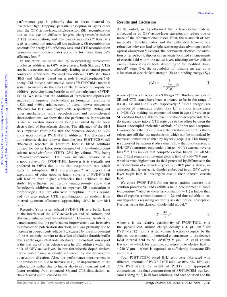
Fig. 4 Performance of P3HT:PCBM bilayer OPVs with PVDF-TrFE as additive in P3HT layer and as an interfacial layer between P3HT and PCBM
layers. (a–c), schematic diagrams of three types of devices fabricated. (d) Photocurrents of P3HT:PCBMbilayer control cells, and cells with PVDF-TrFE
as interfacial layer (interface device) and as additive in the P3HT layer (mixture device). Also shown for these three types of devices are: (e) External
quantum efficiency (EQE) as a function of wavelength; (f) Ratio of EQE at �1 V and 0V bias. (g) PL lifetime plots for the three types of structures.
Arrow shows order of decreasing lifetimes (control > mixture > interface).
Table 2 Effect of PVDF-TrFE placement on the photovoltaic param-eters of bilayer OPVs
Jsc (mA cm�2) Voc (V) FF Efficiency
Control bilayer 5 0.4 39 0.8%Mixture bilayer 7.1 0.4 45 1.3%Interface bilayer 4.2 0.5 35 0.7%
Dow
nloa
ded
by I
owa
Stat
e U
nive
rsity
on
02 M
ay 2
012
Publ
ishe
d on
23
Febr
uary
201
2 on
http
://pu
bs.r
sc.o
rg |
doi:1
0.10
39/C
2EE
0347
8F
View Online
interfacial case than in the mixture case. If the above speculation
is true, we can confidently say that in the mixture device and BHJ
devices, ferroelectric dipoles help to harness both types of SEs,
ones that will otherwise decay radiatively, or non-radiatively.
This journal is ª The Royal Society of Chemistry 2012
Conclusions
In summary, we showed that a ferroelectric additive in the bulk
of OPV active-layers leads to better device performance due to
higher photocurrent and fill-factor. Optical absorption, and
dependence of device performance on ferroelectric-poling
revealed that the optical effects and improved charge transport,
respectively, are not the improvement mechanisms. Upon addi-
tion of PVDF-TrFE, IQE of BHJ devices approached 100% for
some wavelengths, which meant near complete exciton (SE and
CTE) harvesting at these photon energies. Enhanced SE disso-
ciation was also predicted by device simulations and verified by
PL lifetime measurements. Efficiency and exciton-dissociation
Energy Environ. Sci., 2012, 5, 7042–7049 | 7047
Dow
nloa
ded
by I
owa
Stat
e U
nive
rsity
on
02 M
ay 2
012
Publ
ishe
d on
23
Febr
uary
201
2 on
http
://pu
bs.r
sc.o
rg |
doi:1
0.10
39/C
2EE
0347
8F
View Online
enhancement was also observed for bilayer OPVs with PVDF-
TrFE additive in the P3HT layer, which showed that observed
enhancements do not have their origin in morphological changes.
Thus, our investigations show that utilizing ferroelectrics as
additives is a promising methodology for alleviating the depen-
dence of OPV performance on short SE diffusion lengths, and
CTE recombination.
Experimental
Anode preparation
Indium-doped tin oxide (ITO; Delta Technologies) coated
glass slides were cleaned by sonication in isopropanol,
acetone, detergent, ethanol, methanol, and deionized water.
The ITO substrates were then blown dry with nitrogen
and exposed to air plasma (Harrick Scientific) for 5 min.
A poly(ethylenedioxythiophene):poly(styrenesulfonic acid)
(PEDOT:PSS; H C Stark) film was spin-coated (3,000 rpm for
60 s) onto the treated substrates, and the casted films were
annealed on a hot plate at 120 �C for 10 min.
Fabrication of BHJ OPVs
Three solutions were prepared of PVDF-TrFE copolymer
(70 : 30 mol%; PiezoTech) in tetrahydrofuran (THF; Sigma-
Aldrich) with concentrations 2mg ml�1, 4mg ml�1 and 8mg ml�1.
The donor–acceptor blend with 1 : 1 weight ratio (P3HT:PCBM;
NANO C, Inc.) and 13.33 mg ml�1 concentration in ortho-
Dichlorobenzene (ODCB; Sigma-Aldrich) was used. 0.25 ml of
pure THF and 3 PVDF-TrFE solutions (2, 4 and 8mg ml�1) in
THF were mixed with 0.75 ml of blend solution to get 4 solutions
with 0, 5, 10 and 20% PVDF by weight of P3HT. This allowed to
have final concentration of P3HT:PCBM same (10mg ml�1) in all
4 solutions, with each solution having same ratio of THF and
ODCB solvents (1 : 3) to ensure appropriate comparison. The
solvent mixtures was required because PVDF-TrFE does not
dissolve in ODCB, and hence was dissolved in THF and then
mixed with the blend solution in 3 different concentrations. The
solutions were magnetically stirred for several hours at 45 �C.The solutions were then spin coated at 600 rpm for 40 s over
PEDOT:PSS layer and dried at room temperature under a petri
dish. Finally, Al (100 nm) cathode was deposited by thermal
evaporation, and devices were annealed at 150 �C for 2 min.
Fabrication of bilayer OPVs
First, two solutions (PS1 and PS2) were prepared (for subsequent
use in making a next set of solutions) in an argon atmosphere:
PS1 consisted of P3HT in ODCB at a concentration of 26.67 mg
ml�1 and PS2 comprised PVDF-TrFE in THF at a concentration
of 8mg mL�1. Next, four film solutions (FS1, FS2, FS3 and FS4)
were made (for depositing OPV layers). FS1 consisted 0.75 ml of
PS1 mixed with 0.25 ml of PS2 to give a P3HT(ODCB):PVDF-
TrFE(THF) ratio of 20 : 2. FS2 comprised of 0.75 ml of PS1
mixed with 0.25ml THF to give 20 mg mL�1 P3HT:(ODCB +
THF). FS3 contained PCBM in dicholoromethane at a concen-
tration of 10 mg mL�1. FS4 included PVDF in dimethylforma-
mide at a concentration of 2mg mL�1. FS1/FS2, FS3 and FS4
were heated to 45 �C, 0 �C and 65 �C, respectively, and
7048 | Energy Environ. Sci., 2012, 5, 7042–7049
magnetically stirred for several hours. After being cooled to
room temperature, the P3HT solutions (FS1 and FS2) were then
filtered and spin-cast at 1,000 rpm for 90 s onto the dried
PEDOT:PSS coated ITO films, producing a film thickness of
�115 nm. For the three devices presented here, (i) the control
device, (ii) the mixture device and (iii) the interface device, FS2,
FS1 and FS2 solutions were casted, respectively. The films were
then covered with a petri dish and allowed to dry for $ 10 min.
FS4 was then filtered and spun at 4,000 rpm for 60 s onto the
P3HT:(ODCB + THF) layer of the interface device, producing
an interfacial film thickness of <10 nm. This film was then
annealed on at 150 �C for 1 min. The device was again covered
and the interface film was allowed to cool. FS3 was then filtered
and spin-cast (4,000 rpm for 10 s) to a thickness of �34 nm onto
all three devices and was immediately annealed at 150 �C for
1 min. After allowing the films to cool, a �100 nm thick Al
cathode was evaporated on all devices at a rate <5 �A s�1.
Photovoltaic characterization
J–V characterization was done using ELH Quartzline halogen
lamp, the intensity of which was calibrated using a crystalline Si
cell with a KG-5 filter. EQE measurements were also done using
this lamp and a monochromator with a lock-in amplifier. The
reference was a calibrated Si photodiode with known EQE
spectra. To calculate IQE of the BHJ devices, all the films for
absorption measurement were spun cast on glass substrates. The
absorption spectra were measured in Varian Cary 5000 UV-Vis-
NIR spectrophotometer.
Time resolved photoluminescence experiments
Excited-state PL-lifetime measurements were performed using
the set-up described elsewhere.30 Briefly, a homebuilt mode-
locked Ti:sapphire oscillator pumped by a Nd:VO4 laser
(Millennia, Spectra Physics) producing femtosecond pulses
tunable from 780 to 900 nm with a repetition rate of 82 MHz was
used as the laser source. The fundamental wavelength at 814 nm
from the Ti:sapphire oscillator was modulated by a Pockels cell
(Model 350-160, Conoptics Inc.) to reduce the repetition rate to
approximately 8.8 MHz and was subsequently frequency-
doubled by using a harmonic generator (Model TP- 2000B,
U-Oplaz Technologies). The resulting blue light, which had
a central wavelength of 407 nm, provided the excitation source,
and emission (l > 505 nm) was collected in front face geometry
from solid films using appropriate filters to eliminate possible
interference from scattered light. The full width at half-maximum
of the instrument response function was �35 ps. All of the
measurements were made in a 3.33 ns time window with a total of
1024 channels. A total of 65530 counts were collected at the peak
channel for all of the lifetime measurements.
Acknowledgements
This work was supported by National Science Foundation
(Award # ECCS-1055930), Iowa Power Fund and Institute of
Physical Research and Technology, Iowa State University. PL
lifetime studies were supported by the U.S. Department of
Energy, Office of Basic Energy Sciences, through the Ames
Laboratory. The Ames Laboratory is operated for the U.S.
This journal is ª The Royal Society of Chemistry 2012

Dow
nloa
ded
by I
owa
Stat
e U
nive
rsity
on
02 M
ay 2
012
Publ
ishe
d on
23
Febr
uary
201
2 on
http
://pu
bs.r
sc.o
rg |
doi:1
0.10
39/C
2EE
0347
8F
View Online
Department of Energy by Iowa State University under Contract
No. DE-AC02-07CH11358
Notes and references
1 H. Y. Chen, J. H. Hou, S. Q. Zhang, Y. Y. Liang, G. W. Yang,Y. Yang, L. P. Yu, Y.Wu andG. Li,Nat. Photonics, 2009, 3, 649–653.
2 Y. Y. Liang, Z. Xu, J. B. Xia, S. T. Tsai, Y. Wu, G. Li, C. Ray andL. P. Yu, Adv. Mater., 2010, 22, E135–E138.
3 S. H. Park, A. Roy, S. Beaupre, S. Cho, N. Coates, J. S. Moon,D. Moses, M. Leclerc, K. Lee and A. J. Heeger, Nat. Photonics,2009, 3, 297–U295.
4 G. Li, V. Shrotriya, J. S. Huang, Y. Yao, T. Moriarty, K. Emery andY. Yang, Nat. Mater., 2005, 4, 864–868.
5 G. Li, Y. Yao, H. Yang, V. Shrotriya, G. Yang and Y. Yang, Adv.Funct. Mater., 2007, 17, 1636–1644.
6 W. L. Ma, C. Y. Yang, X. Gong, K. Lee and A. J. Heeger,Adv. Funct.Mater., 2005, 15, 1617–1622.
7 J. Peet, J. Y. Kim, N. E. Coates, W. L. Ma, D. Moses, A. J. Heegerand G. C. Bazan, Nat. Mater., 2007, 6, 497–500.
8 Y. Yao, J. H. Hou, Z. Xu, G. Li and Y. Yang, Adv. Funct. Mater.,2008, 18, 1783–1789.
9 S. Miller, G. Fanchini, Y. Y. Lin, C. Li, C. W. Chen, W. F. Su andM. Chhowalla, J. Mater. Chem., 2008, 18, 306–312.
10 T. Kirchartz, K. Taretto and U. Rau, J. Phys. Chem. C, 2009, 113,17958–17966.
11 J. Liu, Y. J. Shi and Y. Yang, Adv. Funct. Mater., 2001, 11, 420–424.12 Y. B. Yuan, T. J. Reece, P. Sharma, S. Poddar, S. Ducharme,
A.Gruverman,Y.YangandJ. S.Huang,Nat.Mater., 2011,10, 296–302.13 K. Asadi, P. de Bruyn, P. W. M. Blom and D. M. de Leeuw, Appl.
Phys. Lett., 2011, 98, 183301.
This journal is ª The Royal Society of Chemistry 2012
14 Z. Zhou, R. Shinar, A. J. Allison and J. Shinar, Adv. Funct. Mater.,2007, 17, 3530–3537.
15 M. Wojcik and M. Tachiya, J. Chem. Phys., 2009, 130, 104107.16 C. Deibel, D. Mack, J. Gorenflot, A. Scholl, S. Krause, F. Reinert,
D. Rauh and V. Dyakonov, Phys Rev B, 2010, 81.17 X. Y. Zhu, Q. Yang and M. Muntwiler, Acc. Chem. Res., 2009, 42,
1779–1787.18 V. D. Mihailetchi, L. J. A. Koster, J. C. Hummelen and
P. W. M. Blom, Phys. Rev. Lett., 2004, 93, 216601.19 P. Peumans, A. Yakimov and S. R. Forrest, J. Appl. Phys., 2003, 93,
3693–3723.20 Z. Y. Cheng and Q. M. Zhang, MRS Bull., 2008, 33, 183–187.21 D. Shvydka and V. G. Karpov, Appl. Phys. Lett., 2008, 92,
053507.22 K. H. Lee, G. Lee, K. Lee, M. S. Oh, S. Im and S. M. Yoon, Adv.
Mater., 2009, 21, 4287–4291.23 M. Wegener, Rev. Sci. Instrum., 2008, 79, 106103.24 R. Naber, B. De Boer, P. Blom and D. De Leeuw, Appl. Phys. Lett.,
2005, 87, 203509.25 G. F. Burkhard, E. T. Hoke and M. D. McGehee, Adv. Mater., 2010,
22, 3293–3297.26 G. F. Burkhard, E. T. Hoke, S. R. Scully and M. D. McGehee, Nano
Lett., 2009, 9, 4037–4041.27 K. H. Lee, P. E. Schwenn, A. R. G. Smith, H. Cavaye, P. E. Shaw,
M. James, K. B. Krueger, I. R. Gentle, P. Meredith and P. L. Burn,Adv. Mater., 2011, 23, 766.
28 K. Vandewal, K. Tvingstedt, A. Gadisa, O. Inganas and J. V. Manca,Nat. Mater., 2009, 8, 904–909.
29 M. I. Khan, G. C. Bazan and Z. D. Popovic, Chem. Phys. Lett., 1998,298, 309–314.
30 S. Bose, R. Adhikary, P. Mukherjee, X. Y. Song and J. W. Petrich, J.Phys. Chem. B, 2009, 113, 11061–11068.
Energy Environ. Sci., 2012, 5, 7042–7049 | 7049


![Characteristics of ZnO-based semiconductor ceramics doped ... · ferromagnetic and ferroelectric materials [7]. The outer electronic structure of germanium is the same as silicon,](https://static.cupdf.com/doc/110x72/5f2f12b9a1d1cb2992198a07/characteristics-of-zno-based-semiconductor-ceramics-doped-ferromagnetic-and.jpg)