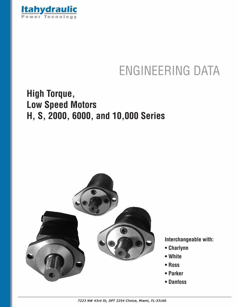
High Torque, Low Speed MotorsH, S, 2000, 6000, and 10,000 Series
Interchangeable with:
• Charlynn
• White
• Ross
• Parker
• Danfoss
ENGINEERING DATA

Technical Data Summary:
Model Distributor Displacement Maximum Speedtype Operating Pressure RPM
in3/rev cm3/rev PSI BAR
H Series Axial 3-23 50-400 2400 163 30-800
S Series Axial 3-23 50-375 3000 200 30-970
2000 Series Disc 5-23 80-375 3250 225 30-800
6000 Series Disc 10-49 160-800 3400 240 30-705
10,000 Series Disc 19-49 315- 800 4000 280 10-446
HIGH TORQUE, LOW SPEED MOTORS
Extensive range of multiple displacement Low Speed – High Torque (LSHT) hydraulic motors are form fit and function interchangeable with many of the common motor products from Parker, White, Charlynn and Danfoss.Both Geroter and Geroler technologies are incorporated in the “H” Series, “S” series, “2000” series,“6000” series and “10,000” series.
These motors are manufactured with ISO 9001:2000 documented quality standards which results inproduct which consistently meets or exceeds the life and performance expectations of similar products. The product is built to perform in even the harsh environments where rugged mobile equipment is ex-pected to operate. For optimal life the following guidelines are recommended:
1) Motors should be operated at less than 30% of full rated performance for the first hour of operation
2) During normal sustained operations, oil temperature should be between 70 to 150 degrees F (20 to 60 degrees C)
3) Maximum operating temperature should not exceed 190 degrees F (90 degrees C)
4) ISO oil cleanliness level should be 18/13 or cleaner. Normally this is achieved with Beta 10=100 full flow return line filtration.
5) High grade petroleum based hydraulic oil must be used
6) Minimum oil viscosity should be 100 SUS
7) Simultaneous maximum torque and maximum speed is not recommend for this design of motor

H-SERIESThe -101 (H) Geroter™ gear set, spool valve flow distribution, hydraulic motors are a compact, highly efficient, low speed-high torque design which can be used in either parallel or series systems. These low weight advanced construction designmotors are manufactured in accordance with the requirements of the ISO 9001:2000 quality system.
Technical Specifications
Continuous = maximum of continuous operationIntermittent = maximum operating range for 6 seconds per minute
HIGH TORQUE, LOW SPEED MOTORS
101 H SERIES
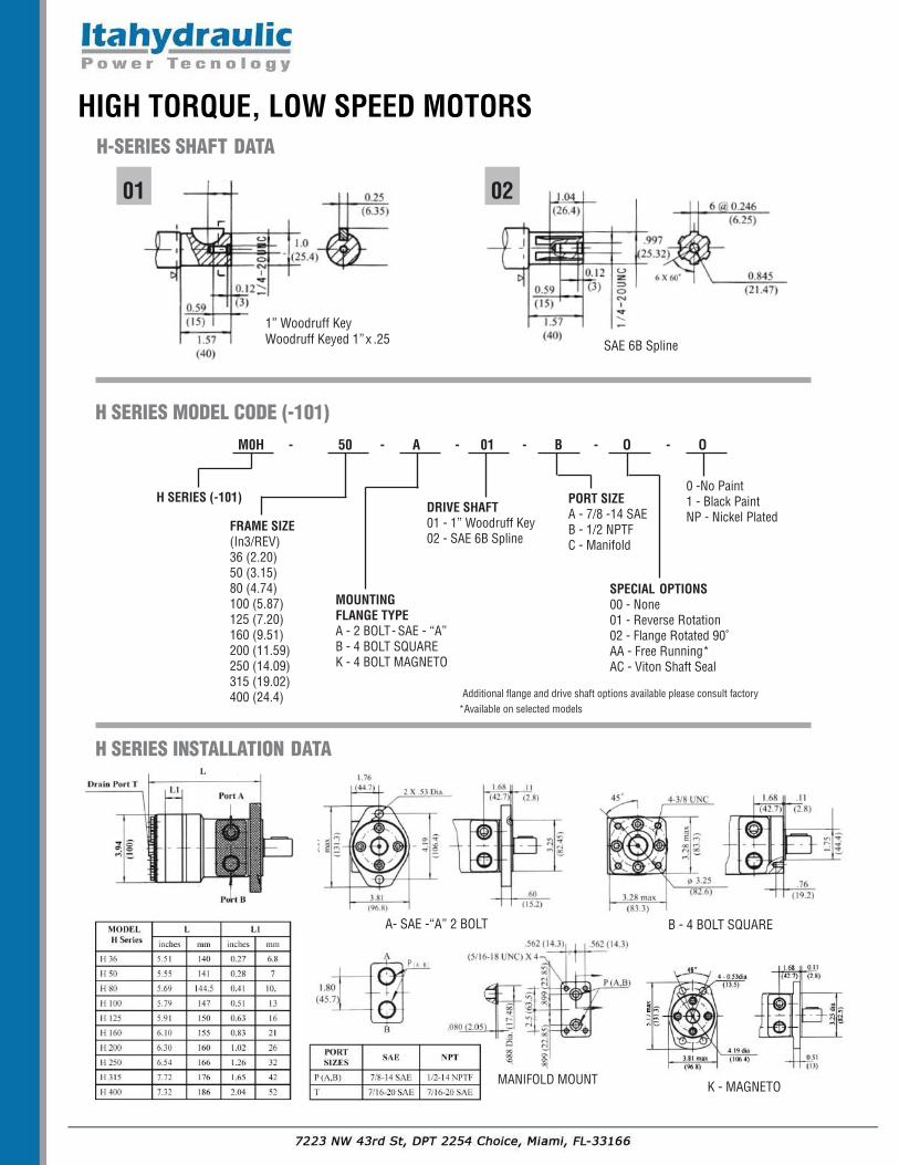
M0H - 50 - A - 01 - B - O - O
H SERIES (-101)
FRAME SIZE(In3/REV)36 (2.20)50 (3.15)80 (4.74)100 (5.87)125 (7.20)160 (9.51)200 (11.59)250 (14.09)315 (19.02)400 (24.4)
H SERIES MODEL CODE (-101)
MOUNTINGFLANGE TYPEA - 2 BOLT- SAE - “A” B - 4 BOLT SQUAREK - 4 BOLT MAGNETO
DRIVE SHAFT01 - 1” Woodruff Key02 - SAE 6B Spline
PORT SIZEA - 7/8 -14 SAEB - 1/2 NPTFC - Manifold
SPECIAL OPTIONS00 - None01 - Reverse Rotation02 - Flange Rotated 90˚AA - Free Running*AC - Viton Shaft Seal
0 -No Paint 1 - Black PaintNP - Nickel Plated
Additional flange and drive shaft options available please consult factory*Available on selected models
K - MAGNETOMANIFOLD MOUNT
H-SERIES SHAFT DATA
A- SAE -“A” 2 BOLT B - 4 BOLT SQUARE
SAE 6B Spline
01 02
1” Woodruff KeyWoodruff Keyed 1”x .25
H SERIES INSTALLATION DATA
HIGH TORQUE, LOW SPEED MOTORS
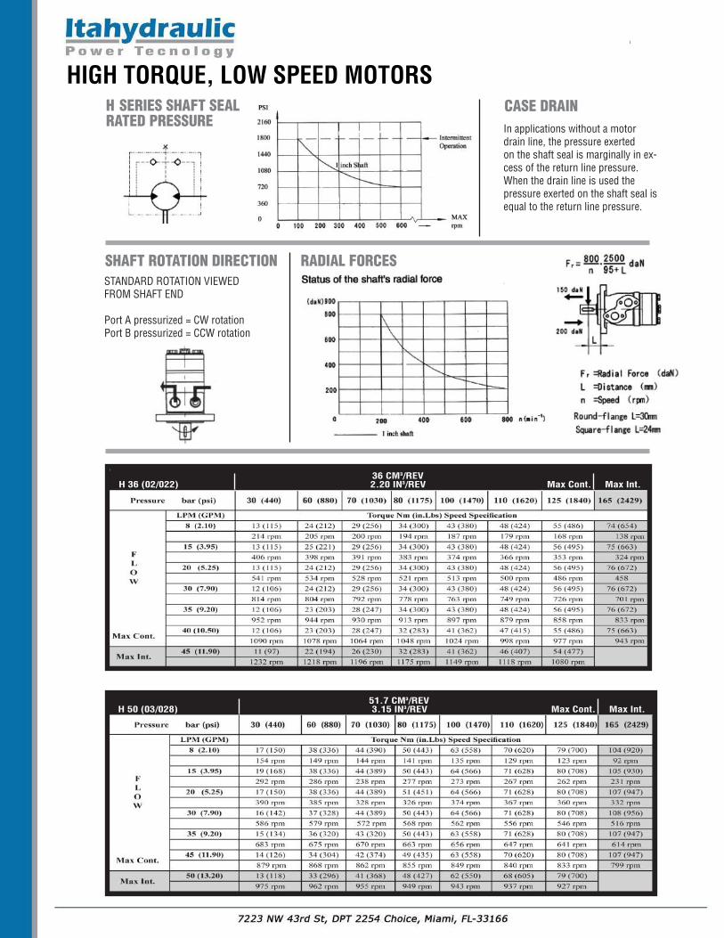
CASE DRAINIn applications without a motordrain line, the pressure exerted on the shaft seal is marginally in ex-cess of the return line pressure.When the drain line is used thepressure exerted on the shaft seal isequal to the return line pressure.
SHAFT ROTATION DIRECTION RADIAL FORCESSTANDARD ROTATION VIEWED FROM SHAFT END
Port A pressurized = CW rotationPort B pressurized = CCW rotation
36 CM3/REVH 36 (02/022) 2.20 IN3/REV Max Cont. Max Int.
51.7 CM3/REVH 50 (03/028) 3.15 IN3/REV Max Cont. Max Int.
H SERIES SHAFT SEAL RATED PRESSURE
HIGH TORQUE, LOW SPEED MOTORS
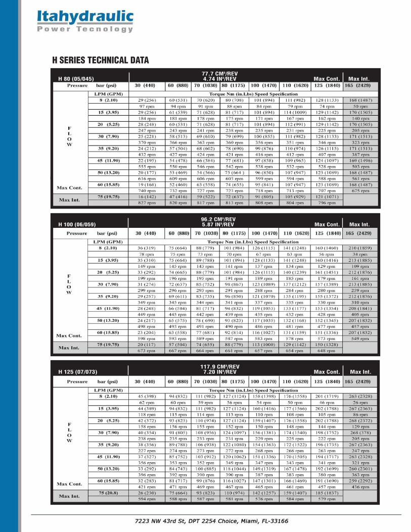
77.7 CM3/REVH 80 (05/045) 4.74 IN3/REV Max Cont. Max Int.
96.2 CM3/REVH 100 (06/059) 5.87 IN3/REV Max Cont. Max Int.
117.9 CM3/REVH 125 (07/073) 7.20 IN3/REV Max Cont. Max Int.
H SERIES TECHNICAL DATA
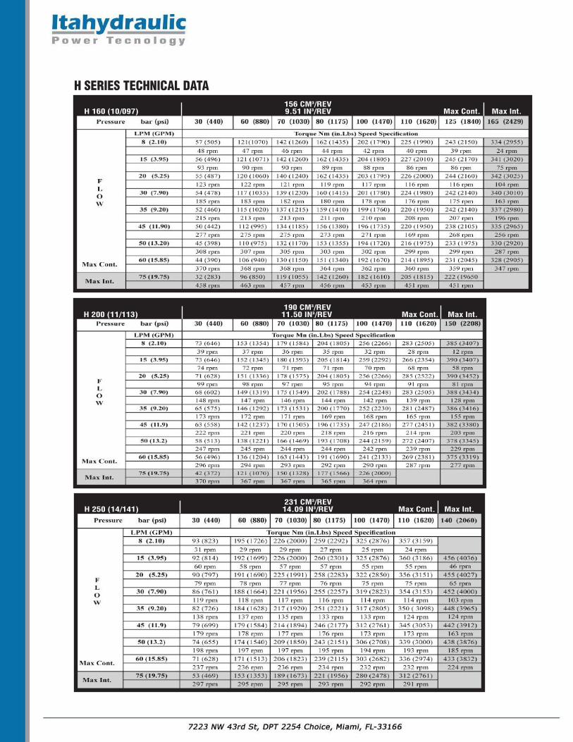
156 CM3/REVH 160 (10/097) 9.51 IN3/REV Max Cont. Max Int.
190 CM3/REVH 200 (11/113) 11.50 IN3/REV Max Cont. Max Int.
231 CM3/REVH 250 (14/141) 14.09 IN3/REV Max Cont. Max Int.
H SERIES TECHNICAL DATA

312 CM3/REVH 315 (18/179) 19.03 IN3/REV Max Cont. Max Int.
387 CM3/REVH 400 (23/226) 23.61 IN3/REV Max Cont. Max Int.
H SERIES TECHNICAL DATA
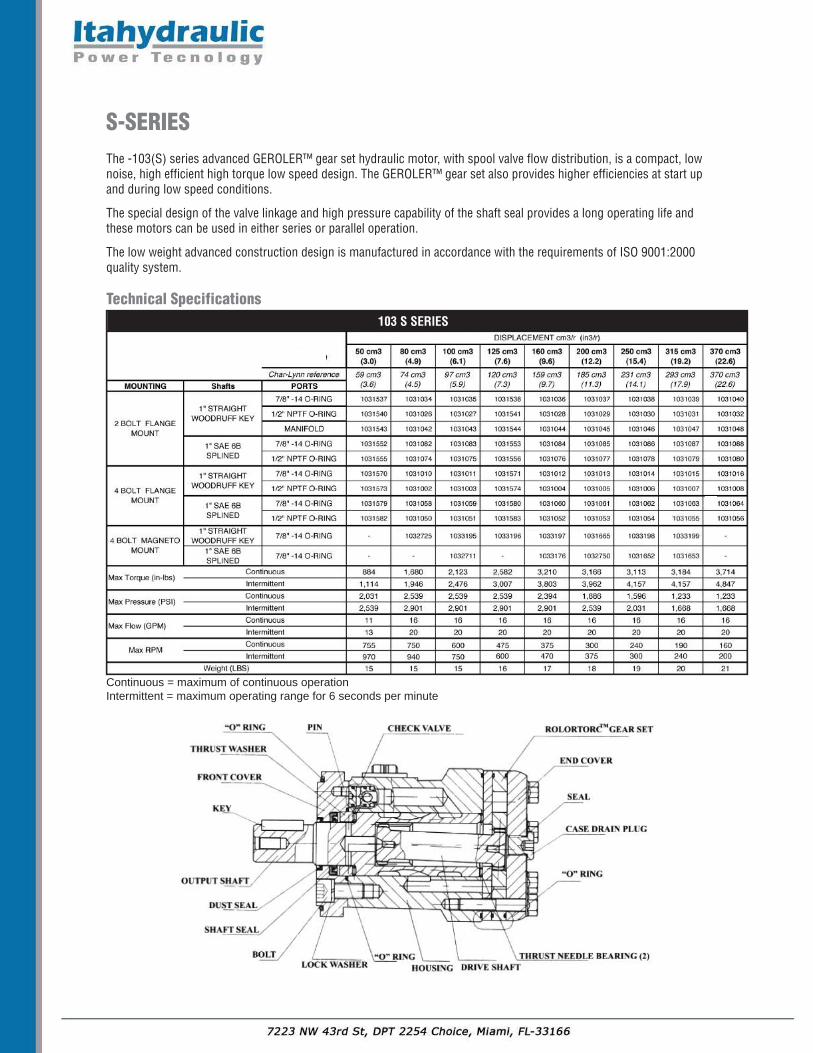
S-SERIESThe -103(S) series advanced GEROLER™ gear set hydraulic motor, with spool valve flow distribution, is a compact, lownoise, high efficient high torque low speed design. The GEROLER™ gear set also provides higher efficiencies at start upand during low speed conditions.
The special design of the valve linkage and high pressure capability of the shaft seal provides a long operating life andthese motors can be used in either series or parallel operation.
The low weight advanced construction design is manufactured in accordance with the requirements of ISO 9001:2000quality system.
Technical Specifications
Continuous = maximum of continuous operationIntermittent = maximum operating range for 6 seconds per minute
103 S SERIES
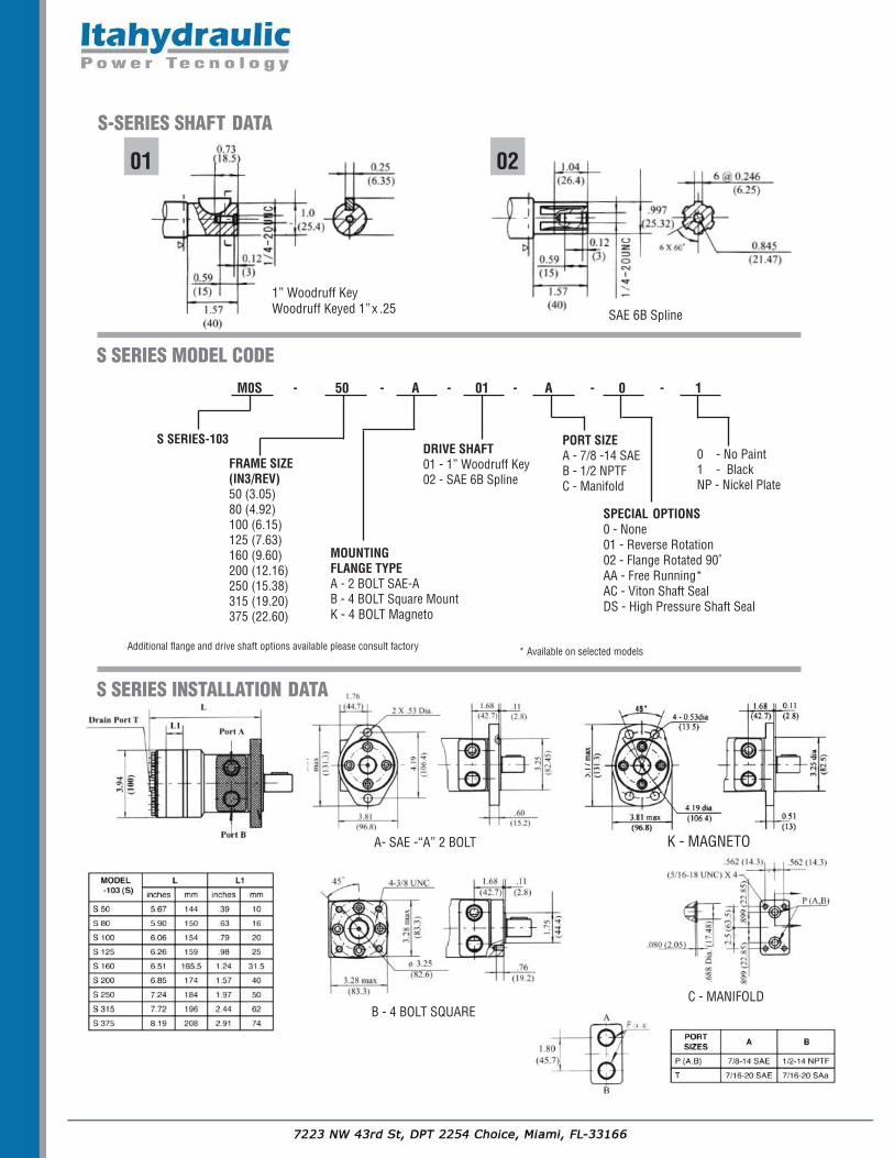
M0S - 50 - A - 01 - A - 0 - 1
S SERIES-103
FRAME SIZE(IN3/REV)50 (3.05)80 (4.92)100 (6.15)125 (7.63)160 (9.60)200 (12.16)250 (15.38)315 (19.20)375 (22.60)
S SERIES MODEL CODE
MOUNTINGFLANGE TYPEA - 2 BOLT SAE-AB - 4 BOLT Square MountK - 4 BOLT Magneto
DRIVE SHAFT01 - 1” Woodruff Key02 - SAE 6B Spline
PORT SIZEA - 7/8 -14 SAEB - 1/2 NPTFC - Manifold
0 - No Paint1 - BlackNP - Nickel Plate
SPECIAL OPTIONS0 - None01 - Reverse Rotation02 - Flange Rotated 90˚AA - Free Running*AC - Viton Shaft SealDS - High Pressure Shaft Seal
Additional flange and drive shaft options available please consult factory
SAE 6B Spline
01 02
* Available on selected models
S-SERIES SHAFT DATA
A- SAE -“A” 2 BOLT K - MAGNETO
B - 4 BOLT SQUAREC - MANIFOLD
S SERIES INSTALLATION DATA
1” Woodruff KeyWoodruff Keyed 1”x .25
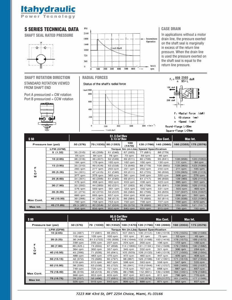
S SERIES TECHNICAL DATA CASE DRAINIn applications without a motordrain line, the pressure exertedon the shaft seal is marginallyin excess of the return linepressure. When the drain lineis used the pressure exerted onthe shaft seal is equal to the return line pressure.
SHAFT ROTATION DIRECTION RADIAL FORCESSTANDARD ROTATION VIEWED FROM SHAFT END
Port A pressurized = CW rotationPort B pressurized = CCW rotation
SHAFT SEAL RATED PRESSURE
51.3 Cm3/Rev S 50 3.13 in3/Rev Max Cont. Max Int.
80.6 Cm3/Rev S 80 4.9 in3/Rev Max Cont. Max Int.
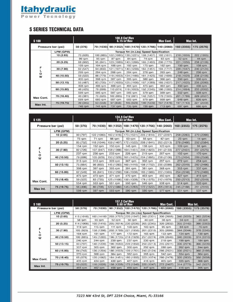
100.8 Cm3/Rev S 100 6.15 in3/Rev Max Cont. Max Int.
124.9 Cm3/Rev S 125 7.63 in3/Rev Max Cont. Max Int.
157.2 Cm3/Rev S 160 9.60 in3/Rev Max Cont. Max Int.
S SERIES TECHNICAL DATA
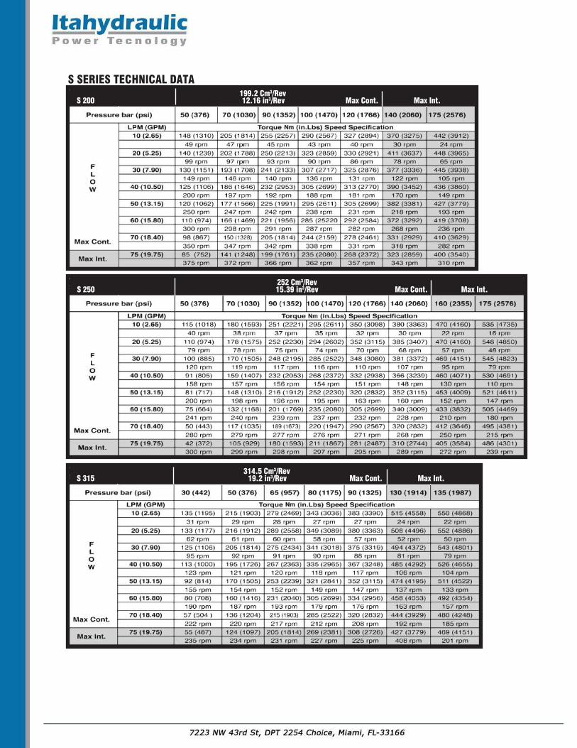
199.2 Cm3/Rev S 200 12.16 in3/Rev Max Cont. Max Int.
314.5 Cm3/Rev S 315 19.2 in3/Rev Max Cont. Max Int.
252 Cm3/Rev S 250 15.39 in3/Rev Max Cont. Max Int.
S SERIES TECHNICAL DATA
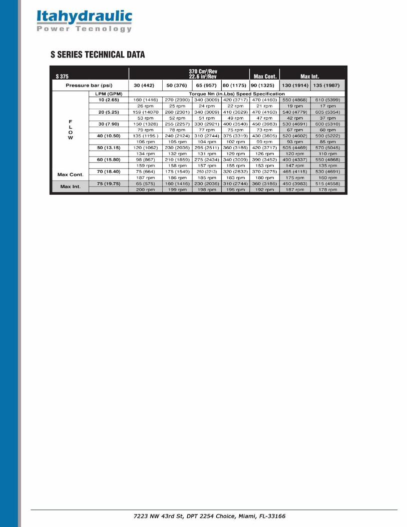
370 Cm3/Rev S 375 22.6 in3/Rev Max Cont. Max Int.
S SERIES TECHNICAL DATA

2000-SERIESThe 2000 series motor adapts the advanced Geroler™ gear set design with DISC flow distribution and high pressure. The output shaft tapered roller bearings permit high axial and radial forces offering a smooth operation during low pressure start up and high pressure operation. These low weight advanced construction design motors are manufactured in accordance with the requirements of the ISO 9001:2000 quality system.
Technical Specifications
Continuous = maximum of continuous operationIntermittent = maximum operating range for 6 seconds per minute
104 2000 SERIES

M02 - 200 - AC - 01 - AG - 1 - O
2000 SERIES(-104)
FRAME SIZE(IN3/REV)80 (4.90)100 (6.20)125 (7.20)160 (9.59)200 (12.20)250 (15.40)315 (19.20)400 (24.04)475 (28.98)
MODEL CODE - 2000 SERIES
MOUNTINGFLANGE TYPEAC - SAE -“A” 2 BOLTAB - 4 BOLT WheelAF - SAE - “B” 2 BOLTAH - 4 BOLT SquareAJ - 4 BOLT MagnetoAD - 4 BOLT Bearingless
DRIVE SHAFT01 - 1” Woodruff Key02 - 1-1/4” Parallel Key03 - 1-1/4" Tappered Shaft SAE J50104 - 1-1/4" 14 Tooth Spline05 - 1” SAE 6B Spline07 - 7/8" 13 Tooth 16/32 DP
PORT SIZEAA - 7/8” -14 SAE O-RingAB - ManifoldAF - 1 1/16”-12 SAE O-Ring 180˚ ApartAG - G-1/2 BSPAP - All Port (7/8”-14, 1-1/16”-12,
2x3/8” UNC Thread)
0 - No Paint 1 - BlackNP - Nickel Plate
SPECIAL OPTIONS0 -None01 - Viton Seals03 - Free Running*31 - Dual Cross Port Reliefs41 - High Pressure Shaft Seal*B - Reverse Rotation
Additional flange and drive shaft options available please consult factory
01 02
03 04
*Available on selected models
2000-SERIES SHAFT DATA
Shaft 01: 1” woodruff keyedWoodruff key Ø25.4x6.35
Shaft 03: 1-1/4” TaperedParallel key .31x.31x1.0Tightening torque: 200±10Nm
Shaft 04: 1-1/4” 14 Tooth Spline12/24 DP
05 07
Shaft 05: 1” SAE 6B Spline Shaft 07: 7/8”-13 Tooth Spline16/32 DP
Shaft 02: 1-1/4 KeyedParallel key .31x.31x1.25

[INCHES] MILLIMETERS
MODEL L L1 L L180 [6.93] [0.63] 176 16100 [7.09] [0.79] 180 20125 [7.28] [0.98] 185 25160 [7.36] [1.06] 187 27200 [7.64] [1.34] 194 34250 [7.95] [1.65] 202 42315 [8.43] [2.13] 214 54400 [9.02] [2.72] 229 69475 [9.57] [3.27] 243 83
Rear Housing Drain Port
Porting 180˚
[INCHES] MILLIMETERS
MODEL L L1 L2 L L1 L280 [6.81] [.51] [4.95] 173 13 125.7100 [6.97] [.67] [5.11] 177 17 129.7125 [7.17] [.87] [5.30] 182 22 134.7160 [7.38] [1.08] [5.52] 187.5 27.5 140.2200 [7.68] [1.38] [5.81] 195 35.1 147.7250 [8.15] [1.85] [6.29] 207 47 159.7315 [8.62] [2.32] [6.76] 219 59 171.7375 [9.09] [2.80] [7.23] 231 71 183.7
180° APART PORT MOUNTING DATA
DRAIN ON REAR HOUSING
2000 SERIES INSTALLATION DATA
[INCHES] MILLIMETERS
MODEL L L1 L2 L L1 L280 [6.74] [.52] [4.85] 171 13 123.2100 [6.89] [.67] [5.01] 175 17 127.2125 [7.09] [.87] [5.21] 180 22 132.2160 [7.27] [1.09] [5.43] 184.5 27.5 137.7200 [7.60] [1.39] [5.72] 193 35.1 145.2250 [8.07] [1.85] [6.19] 205 47 157.2315 [8.55] [2.33] [6.67] 217 59 169.2375 [9.02] [2.80] [7.14] 229 71 181.2
AB - MANIFOLD
AP - ALL PORTS
ORDER� CODE AG� � � � � Depth AA� � � � � � � � Depth AF� � � � � � � � � � � � Depth
PORTS� -� A� AND� BG 1/2 18 mm M22x1.5 18 mm 7/8-14 O-ring 18 mm
TANK� PORT� -� T G 1/4 12 mm M14x1.5 12 mm 7/16-20 UNF 12 mm
PORT� &� DRAIN� PORT� ORDERING� CODES
ORDER� CODE AF� � � � � � � � � � � � DEPTHPorts 11/16-12 18mmA and B O-Ring
Tank Port -T 7/16-20 UNF 12mm

AF - SAE “B” 2 BOLT AC - SAE “A” 2 BOLT
AH - 4 BOLT SQUARE AJ - 4 BOLT MAGNETO
AB - 4 BOLT WHEEL MOUNT
2000 SERIES INSTALLATION DATA
1.83 (46.5)
CASE DRAIN
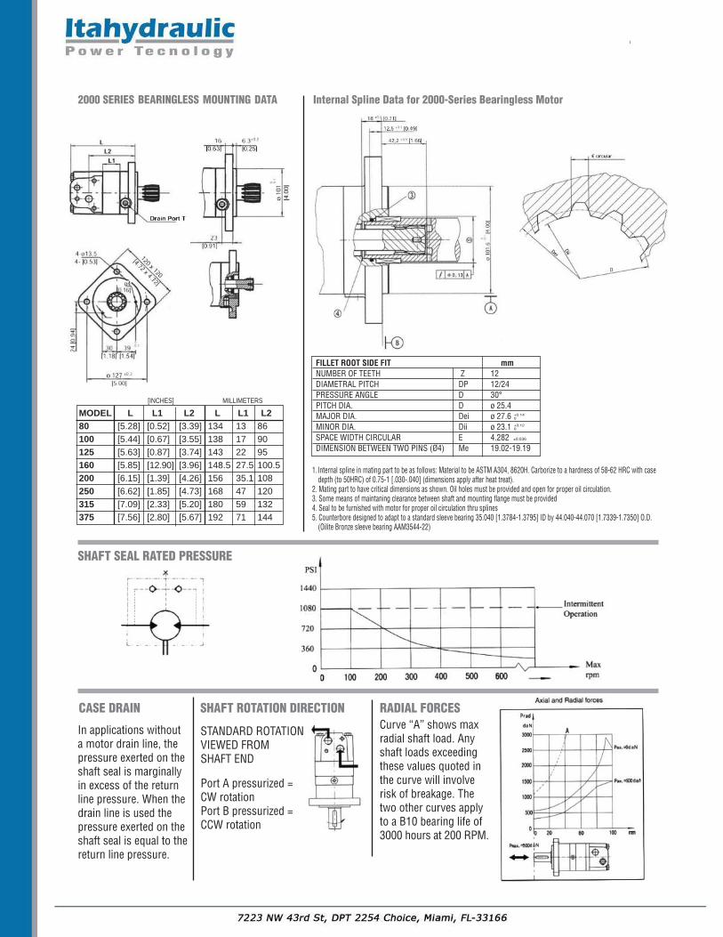
In applications withouta motor drain line, thepressure exerted on theshaft seal is marginallyin excess of the returnline pressure. When thedrain line is used thepressure exerted on theshaft seal is equal to thereturn line pressure.
SHAFT ROTATION DIRECTION RADIAL FORCES
STANDARD ROTATION VIEWED FROM SHAFT END
Port A pressurized =CW rotationPort B pressurized =CCW rotation
Curve “A” shows maxradial shaft load. Anyshaft loads exceedingthese values quoted inthe curve will involve risk of breakage. Thetwo other curves applyto a B10 bearing life of3000 hours at 200 RPM.
SHAFT SEAL RATED PRESSURE
MODEL L L1 L2 L L1 L280 [5.28] [0.52] [3.39] 134 13 86100 [5.44] [0.67] [3.55] 138 17 90125 [5.63] [0.87] [3.74] 143 22 95160 [5.85] [12.90] [3.96] 148.5 27.5 100.5200 [6.15] [1.39] [4.26] 156 35.1 108250 [6.62] [1.85] [4.73] 168 47 120315 [7.09] [2.33] [5.20] 180 59 132375 [7.56] [2.80] [5.67] 192 71 144
[INCHES] MILLIMETERS
2000 SERIES BEARINGLESS MOUNTING DATA Internal Spline Data for 2000-Series Bearingless Motor
FILLET ROOT SIDE FIT mmNUMBER OF TEETH Z 12DIAMETRAL PITCH DP 12/24PRESSURE ANGLE D 30°PITCH DIA. D ø 25.4MAJOR DIA. Dei ø 27.6MINOR DIA. Dii ø 23.1SPACE WIDTH CIRCULAR E 4.282 ±0.036
DIMENSION BETWEEN TWO PINS (Ø4) Me 19.02-19.19
+0.140
+0.120
1. Internal spline in mating part to be as follows: Material to be ASTM A304, 8620H. Carborize to a hardness of 58-62 HRC with casedepth (to 50HRC) of 0.75-1 [.030-.040] (dimensions apply after heat treat).
2. Mating part to have critical dimensions as shown. Oil holes must be provided and open for proper oil circulation.3. Some means of maintaning clearance between shaft and mounting flange must be provided4. Seal to be furnished with motor for proper oil circulation thru splines5. Counterbore designed to adapt to a standard sleeve bearing 35.040 [1.3784-1.3795] ID by 44.040-44.070 [1.7339-1.7350] O.D.
(Oilite Bronze sleeve bearing AAM3544-22)

125 Cm3/Rev 2000 SERIES 125 7.65 in3/Rev Max Cont. Max Int.
2000 SERIES TECHNICAL DATA
100.8 Cm3/Rev 2000 SERIES 100 6.15 in3/Rev Max Cont. Max Int.
80.6 Cm3/Rev 2000 SERIES 80 4.92 in3/Rev Max Cont. Max Int.

2000 SERIES TECHNICAL DATA
243 Cm3/Rev 2000 SERIES 250 14.8 in3/Rev Max Cont. Max Int.
200 Cm3/Rev 2000 SERIES 200 12.2 in3/Rev Max Cont. Max Int.
154 Cm3/Rev 2000 SERIES 160 9.39 in3/Rev Max Cont. Max Int.

2000 SERIES TECHNICAL DATA
475 Cm3/Rev 2000 SERIES 475 28.9 in3/Rev Max Cont. Max Int.
394 Cm3/Rev 2000 SERIES 400 24 in3/Rev Max Cont. Max Int.
311 Cm3/Rev 2000 SERIES 315 18.9 in3/Rev Max Cont. Max Int.

6000-SERIESThe 6000 series motor is a large volume, disc valve, high pressure motor, with a radial ball-bearing design. They are capable ofhandling greater loads and higher torque applications. The advance design in disc distribution flow provides improved perform-ance at low speed. The disc valve compensates for wear providing volumetric efficiencies. The double taper roller bearings allowfor high radial loads making these motors ideal for heavier vehicles in traction drive applications.These low weight advanced construction design motors are manufactured in accordance with the requirements of the ISO9001:2000 quality system.
Technical Specifications
Continuous = maximum of continuous operationIntermittent = maximum operating range for 6 seconds per minute
112 6000 SERIES
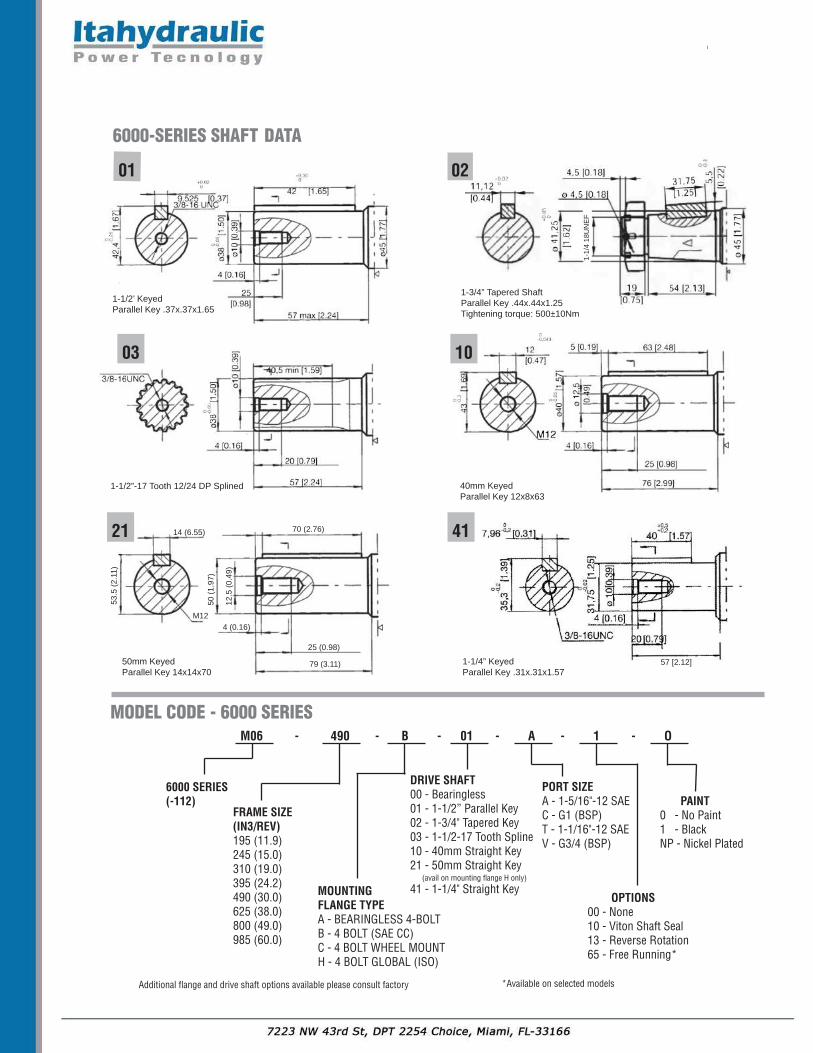
1-1/2’ KeyedParallel Key .37x.37x1.65
M06 - 490 - B - 01 - A - 1 - O
6000 SERIES(-112)
FRAME SIZE(IN3/REV)195 (11.9)245 (15.0)310 (19.0)395 (24.2)490 (30.0)625 (38.0)800 (49.0)985 (60.0)
MODEL CODE - 6000 SERIES
MOUNTINGFLANGE TYPEA - BEARINGLESS 4-BOLTB - 4 BOLT (SAE CC)C - 4 BOLT WHEEL MOUNTH - 4 BOLT GLOBAL (ISO)
DRIVE SHAFT00 - Bearingless01 - 1-1/2” Parallel Key02 - 1-3/4" Tapered Key03 - 1-1/2-17 Tooth Spline10 - 40mm Straight Key21 - 50mm Straight Key
(avail on mounting flange H only)
41 - 1-1/4" Straight Key
PORT SIZEA - 1-5/16"-12 SAEC - G1 (BSP)T - 1-1/16"-12 SAEV - G3/4 (BSP)
PAINT0 - No Paint 1 - BlackNP - Nickel Plated
OPTIONS00 - None10 - Viton Shaft Seal13 - Reverse Rotation65 - Free Running*
Additional flange and drive shaft options available please consult factory
01
*Available on selected models
6000-SERIES SHAFT DATA
02
1-1/2”-17 Tooth 12/24 DP Splined 40mm KeyedParallel Key 12x8x63
03 10
50mm KeyedParallel Key 14x14x70
21
1-1/4” KeyedParallel Key .31x.31x1.57
4170 (2.76)
25 (0.98)
79 (3.11) 57 [2.12]
50 (1.97)
12.5 (0.49)
53.5 (2.11)
M12
14 (6.55)
4 (0.16)
1-3/4” Tapered ShaftParallel Key .44x.44x1.25Tightening torque: 500±10Nm
1-1/4 18UNEF

CASE DRAIN
In applications without amotor drain line, the pressureexerted on the shaft seal ismarginally in excess of the re-turn line pressure. When thedrain line is used the pressureexerted on the shaft seal isequal to the return line pres-sure.
SHAFT ROTATION DIRECTION
STANDARD ROTATION VIEWED FROM SHAFT END
Port A pressurized= CW rotationPort B pressurized= CCW rotation
SHAFT SEAL RATED PRESSURE
BEARINGLESS MOTOR
6000 SERIES INSTALLATION DATA
RADIAL FORCES
H-Global (ISO) Mount
C-Wheel Mount
B-Std SAE CC Mount
G
L1
L5
Ø 160
-0.0
43-0
.063
Ø 127
-0.0
03-0
.008
88 20
13.2 24.5
Ø 127
-0.0
03-0
.008
165 Max4x1/2-13UNC
104
104
147x147
137x137
147x147
178x178
4-Ø18
4-Ø14
4-Ø14.5
4-R12
Ø162
35
38
12.
Dmax
L
Drain
Drain
Ø200
Ø162
pilothigh 13.2
Ø127 -0.003-0.008
pilothigh 9
Ø127 -0-0.1
pilothigh 9
Ø127 -0-0.13
Ø 127
-0 -0.1
3
pilothigh 8
Ø160 -0.043-0.063
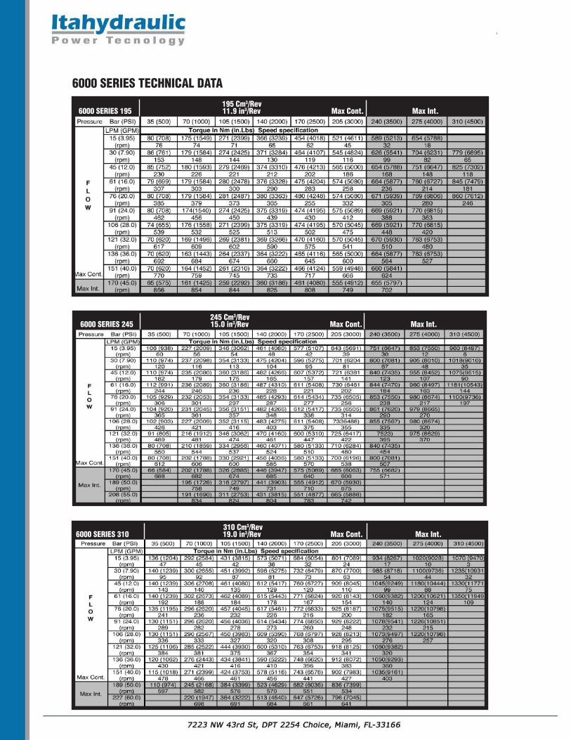
6000 SERIES TECHNICAL DATA
245 Cm3/Rev 6000 SERIES 245 15.0 in3/Rev Max Cont. Max Int.
195 Cm3/Rev 6000 SERIES 195 11.9 in3/Rev Max Cont. Max Int.
310 Cm3/Rev 6000 SERIES 310 19.0 in3/Rev Max Cont. Max Int.

6000 SERIES TECHNICAL DATA
395 Cm3/Rev 6000 SERIES 395 24.17 in3/Rev Max Cont. Max Int.
490 Cm3/Rev 6000 SERIES 490 30.0 in3/Rev Max Cont. Max Int.
625 Cm3/Rev 6000 SERIES 625 38.0 in3/Rev Max Cont. Max Int.

6000 SERIES TECHNICAL DATA
985 Cm3/Rev 6000 SERIES 985 60.0 in3/Rev Max Cont. Max Int.
800 Cm3/Rev 6000 SERIES 800 49.0 in3/Rev Max Cont. Max Int.
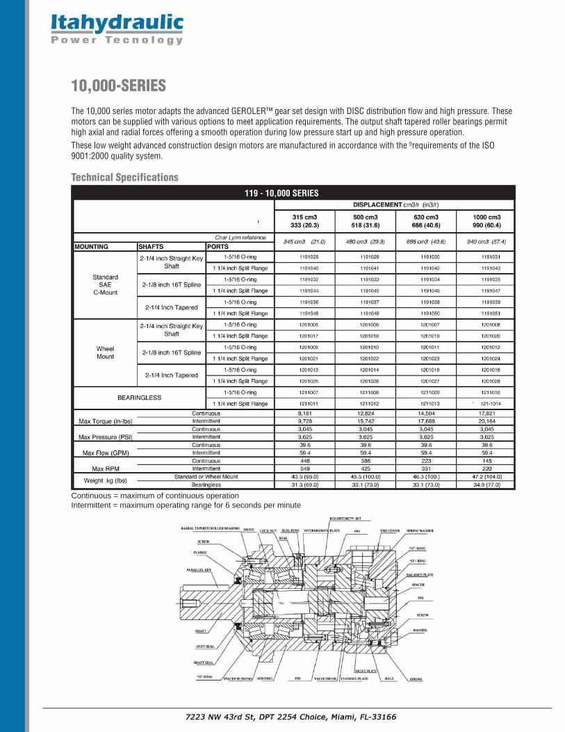
10,000-SERIESThe 10,000 series motor adapts the advanced GEROLER™ gear set design with DISC distribution flow and high pressure. Thesemotors can be supplied with various options to meet application requirements. The output shaft tapered roller bearings permithigh axial and radial forces offering a smooth operation during low pressure start up and high pressure operation.These low weight advanced construction design motors are manufactured in accordance with the º requirements of the ISO9001:2000 quality system.
Technical Specifications
Continuous = maximum of continuous operationIntermittent = maximum operating range for 6 seconds per minute
119 - 10,000 SERIES

M10 - 500 - A - 03 - A - 1 - O
10,000 SERIES
FRAME SIZE(IN3/REV)315 (20.32)500 (31.61)630 (40.64)1000 (60.4)
MODEL CODE - 10,000 SERIES
MOUNTINGFLANGE TYPEA - 4 BOLT SAE CC MountB - 4 BOLT Wheel Mount
DRIVE SHAFT01 - 2-1/4” Parallel Key02 - 2-1/4” Tapered03 - 2-1/8” 16 Tooth Spline
PORT SIZEA - 1-5/16 -12 SAEB - 1-1/4" Split Flange
0 - No Paint A - Black
NP - Nickel Plate
SPECIAL OPTIONS00 - None01 - Free Running*03 - Reverse Rotation
Additional flange and drive shaft options available please consult factory
01 02
*Available on selected models
10,000-SERIES SHAFT DATA
03
2-1/4” Parallel Key 2-1/4” Tapered
2-1/8” 16 Tooth Spline 8/16 DP 30º FRSF
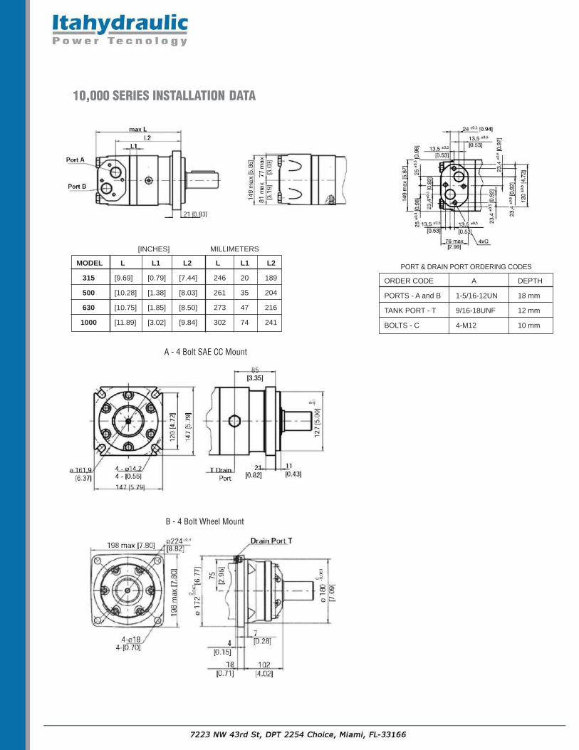
10,000 SERIES INSTALLATION DATA
[INCHES] MILLIMETERS
ORDER CODE A DEPTH
PORTS - A and B 1-5/16-12UN 18 mm
TANK PORT - T 9/16-18UNF 12 mm
BOLTS - C 4-M12 10 mm
PORT & DRAIN PORT ORDERING CODESMODEL� L� L1� L2� L� L1� L2
315� [9.69] [0.79] [7.44] 246 20 189
500� [10.28] [1.38] [8.03] 261 35 204
630 [10.75] [1.85] [8.50] 273 47 216
1000� [11.89] [3.02] [9.84] 302 74 241
A - 4 Bolt SAE CC Mount
B - 4 Bolt Wheel Mount
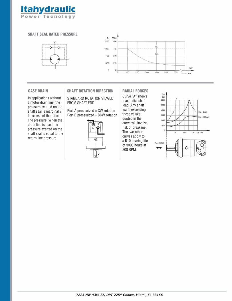
CASE DRAIN
In applications withouta motor drain line, thepressure exerted on theshaft seal is marginallyin excess of the returnline pressure. When thedrain line is used thepressure exerted on theshaft seal is equal to thereturn line pressure.
SHAFT ROTATION DIRECTION RADIAL FORCES
STANDARD ROTATION VIEWED FROM SHAFT END
Port A pressurized = CW rotationPort B pressurized = CCW rotation
SHAFT SEAL RATED PRESSURE
Curve “A” showsmax radial shaftload. Any shaftloads exceedingthese valuesquoted in thecurve will involve risk of breakage.The two othercurves apply to a B10 bearing lifeof 3000 hours at200 RPM.
10,000 SERIES TECHNICAL DATA
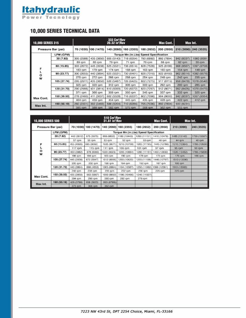
518 Cm3/Rev 10,000 SERIES 500 31.61 in3/Rev Max Cont. Max Int.
333 Cm3/Rev 10,000 SERIES 315 20.32 in3/Rev Max Cont. Max Int.
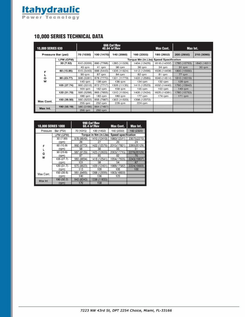
990 Cm3/Rev 10,000 SERIES 1000 60.4 in3/Rev Max Cont. Max Int.
666 Cm3/Rev 10,000 SERIES 630 40.64 in3/Rev Max Cont. Max Int.
10,000 SERIES TECHNICAL DATA