


FA M I LY O V E R V I E W
EncoderSolutions&TechnicalInnovations
■Increment al Encoders
■Absolute Encoders
■Leng th Measur ing Systems

DiscoverSICK|STEGMANN
We are driven to apply new technologies that bring immediate and measurable benefits to our customers.
Quality DesignSICK|STEGMANN products are designed and developed using the most modern methods to ensure performance targets are met. Before and during manufacturing, they are subjected to the most stringent quality controls, using state-of-the-art techniques, and high-precision measuring equipment. SICK|STEGMANN manufacturing plants are ISO 900�:2000 certified, ensuring that customer expectations are met in quotation, order entry, engineering, manufacturing, and after-sale service.
Customer Focused SolutionsFor over 50 years Stegmann has played a vital role as a partner to industry, providing customer-focused solutions. Founded in �956 by the late Max Stegmann, Stegmann was acquired by SICK in 2002. Today SICK|STEGMANN is involved in the design, development, and manufacturing of a diverse range of products. Our expertise, continuous innovation and high standards for precision and quality translate into outstanding performance benefits for our customers.
InnovativeProductsforaWideVarietyofApplications
Technical Innovation Yields Customer Benefits
At SICK|STEGMANN, we are driven to apply new technologies that bring immediate and measurable benefits to our customers. For example:
■ DFS Technology provides higher resolution (up to 65,536 pulses per revolution), metal code disc for improved shock and vibration tolerance, customer programmability of ppr, zero set function and electrical interface, and wider bearing spacing for higher shaft loads and rpms.
■ SSI interface for absolute encoders allows high-resolution, noise-immune feedback with a minimum of wiring expense.
■ CoreTech® factory-configurable incremental and absolute encoders allow 2-3 day shipment of any resolution, as well as high resolution in small packages.
■ CoreTech® customer programmable incremental encoders also are available in 2-3 day delivery times.
These are just a few of the many SICK|STEGMANN product innovations that have become industry standards. In addition, our state-of-the-art production facilities allow superior performance levels to be achieved at reduced costs. This is true in both industrial scale production and customized applications. The result is a competitive cost-performance ratio that translates to added value for our customers.

�SICK|STEGMANN • Ph: 800-8��-9��0 • www.stegmann.com
Application DiversitySICK|STEGMANN encoders are found in a wide range of applications including:
■ Wind power
■ Wind turbines
■ Solar panels
■ Servo motors
■ Packaging machines
■ Machine tools
■ Conveyors
■ Automated storage/retrieval systems
■ Elevators
■ Sheet and web offset presses
■ Medical equipment
■ Robotic systems
■ Food handling equipment
■ Valves/flow metering
■ Overhead cranes
■ Process monitoring equipment
■ Steel making/foundry equipment
■ Textile machinery
■ Tire making equipment
■ Test stands
■ Construction equipment
■ Transportation
page
Encoder Technology 4-6
Incremental Encoders 7-�3Use an incremental encoder when retention of absolute position upon power loss is not required. Examples include velocity control and simple point-to-point applications.
New! DFS Incremental Solutions 8-9
Selection Guide 7, �0-�3
Absolute Encoders �4-�5Use absolute encoders when position data must be retained after loss of power. Examples include robotics, lead/ball screws, overhead cranes, and rack and pinion applications.
Selection Guide �4-�5
page
Linear Encoders &Wire Draw Systems �6-�9Use linear encoders and wire-draw systems to measure incremental or absolute position along any axis. SICK|STEGMANN linear encoders can be used in applications up to �.7 kilometers long!
Selection Guide �8-�9
HIPERFACE® Adapters 20
Accessories 2�
Use our website www.stegmann.com for complete up-to-date information:
■ Product specifications■ Installation guides■ Application examples■ 2D and 3D configurable drawings
Or call one of our application engineers toll-free:
800-811-9110
We look forward to working with you!
TableofContents

2 SICK|STEGMANN • Ph: 800-8��-9��0 • www.stegmann.com
SICK|STEGMANN—YourQualityPartner
At SICK|STEGMANN we define quality as “the value provided to customers and partners through the products and services we offer.”
Supplier of ChoiceSuccessful relationships between customers and suppliers result from the creation of value, trust, and ease of cooperation. Therefore we appreciate any input related to expectations or improvements, and we welcome Customer Audits of our operations. In addition SICK|STEGMANN provides a variety of tools that allow customers easy access to product information, efficient and convenient communication, and direct access to sales and technical support professionals. Our website, www.stegmann.com, not only serves as a comprehensive resource for product information, data sheets, 2D and 3D drawings, installation guides, shipment tracking, and application support, but also features a section exclusively dedicated to quality.
The customer’s perception of value is key, and this perception is shaped by the total experience with SICK|STEGMANN’s performance. This is why we put
great effort into familiarizing our entire organization with the expectations and needs of our customers. In order to ensure that customers’ expectations are met and exceeded, SICK|STEGMANN has adopted a pragmatic approach, where quality is an integral part of all business processes.
Since the introduction of ISO 9000 standards, quality in many organizations has taken on an identity that is detached from other business functions. Similar to our innovative product designs, SICK|STEGMANN’s Management Systems go beyond the conventional scope of typical quality systems. Comprehensive IT tools and controls are employed throughout the entire organization in order to effectively and efficiently manage information, services, design processes, and operations. Thus, customer focus is an integral part of every business aspect — be it product or service.
As visible evidence to our customers, SICK|STEGMANN maintains ongoing registration to ISO 900�:2000.
Customers have direct access to ISO Certificates and our Quality Policy, which outlines the commitment to our customers. The Vision Statement describes how we see the future of the markets we serve, the products we sell, and the organization that delivers them. Our Mission Statement documents what we strive to accomplish through our day-to-day activities. Finally, our Ethics Statement serves as the conscience of the organization. Each statement is supported by measurable objectives, and performance is monitored continuously.
Ultimately our customers decide where they can find the best value. SICK|STEGMANN’s objective is to be their Supplier of Choice.
ComprehensiveServiceandSupport
3SICK|STEGMANN • Ph: 800-8��-9��0 • www.stegmann.com
Information ManagementA management system must be an effective tool for communication. At the core of the SICK|STEGMANN Management Systems are well-defined data process-ing and communication tools that capture, evaluate, and instantly distribute internal and external information throughout the organization, as well as to suppliers and customers. SICK|STEGMANN utilizes the power of elec-tronic technology to docu-ment, manage, and com-plete processes. Digital information exchange in near real-time allows us to generate the valuable feed-back necessary to quickly recognize and respond to critical situations. Custom-ers can transmit any design information directly to our on-site sales and engineering departments, where it be-comes a part of electronically managed and documented design and sales processes.
Environmental ProgramSICK|STEGMANN recognizes and acts on its obligation to preserve and improve our environment through responsible organizational activities. In addition to programs that reduce the waste stream from our manufacturing processes, we have re-designed many of our existing products to comply with RoHS directives. All new product designs will be RoHS compliant.
Quality AssuranceProduct quality begins with proper design. Sound design principles combined with state-of-the-art design tools and years of experience allow us to create products that will perform in unique product applications and harsh environments. Automated calibration and test equipment is considered an integral part of new product designs and is developed exclusively for our products. New product designs benefit from Failure Mode and Effect Analysis and rigorous testing. Customer or internal requirements for First Article Inspection and Production Part Approval will be the
minimum requirement for product acceptance. Products undergo 100% Test and Inspection before they are shipped. Because dependable shipping is important, we continuously monitor and evaluate our on-time delivery performance according to our customers’ ship date requirements.
The SICK|STEGMANN Supplier Management Program improves the quality and delivery of purchased items, and assists our suppliers in developing practical operating procedures for their own organizations.
After-Sale ServiceAll SICK|STEGMANN products are guaranteed against defects in material and workmanship. All products are �00% tested prior to shipment. Individual encoder test reports are recorded and can be supplied if requested by customers. In the unlikely event that you have trouble with our products, many problems can be resolved over the phone. In other situations, we will provide a prompt repair or replacement.
In the event that products are damaged during operation or handling, SICK|STEGMANN maintains a Service Center that will diagnose the problem, inform the customer about the findings, and perform repairs. This process is integrated into our information management tools.
Continual ImprovementNo Management System is ever perfect. At SICK|STEGMANN we understand that there is the need to continuously strive to identify, develop, and implement improvements in order to increase efficiency, product quality, and customer service. We hold ourselves accountable to a high level of performance with the intent of setting the standard for our industry.
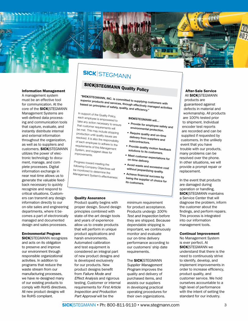
SICK|STEGMANN Quality Policy“SICK|STEGMANN, INC. is committed to supplying customers with superior products and services, through effectively managed activities based on principles of safety, quality, and efficiency.”
In support of the Quality Policy, each employee is empowered to take any action necessary to ensure that customer requirements will be met. This may include stopping production until quality issues are resolved. It is also the responsibility of each employee to adhere to the requirements of this Management System, and suggest ideas for improvements.
Progress toward meeting the following Company Objectives will be monitored to determine the Management System’s effectiveness:
SICK|STEGMANN will…• Provide for employee safety and environmental protection.
• Require quality and on-time delivery from suppliers and subcontractors.• Provide quality motion feedback solutions to its customers.
• Meet customer expectations for on-time delivery.• Avoid waste and excessive cost without jeopardizing quality.
• Achieve financial success by being the supplier of choice for its customers.

4 SICK|STEGMANN • Ph: 800-8��-9��0 • www.stegmann.com
SICK|STEGMANN manufactures various types and sizes of incremental and absolute encoders. Technical information regarding both are provided on the next three pages, as well as an explanation of when to use an incremental versus an absolute encoder.
Electronics board(Signal conditioning)
LED light source
Stationary mask
Photodetector
Rotatingencoder disk
IncrementalEncodersUse an incremental encoder when retention of absolute position upon power loss is not required. Examples include velocity control and simple point-to-point applications.
TechnicalOverviewandDifferencesofIncrementalandAbsoluteEncoders
A Channel
B Channel
QuadratureSignal
The basic structure of an incremental encoder with conventional code disk.
A
A
B
B
As the code disk rotates in front of the stationary mask, it shutters light from the LED. The light that passes through the mask is received by the photodetector, which produces pulses in the form of a quasi-sine wave. The encoder electronics convert the sine wave into a square signal, ready for transmission to a counter.
Conventional Code DisksConventional incremental code disks contain a fixed number of equally spaced opaque lines that produce a corresponding number of pulses per revolution (PPR). Each line count requires a unique code disk. The position and spacing of the lines on the disk requires a high degree of precision. Physical limitations determine the maximum number of lines that can be created on a code disk of a given size.
However, with new technology created by SICK|STEGMANN, our new DFS family will allow up to 65,536 lines and certain versions of the encoder will allow the customer to program it and reprogram it to various line counts, as needed.
Basic Operation of Optical Rotary Incremental EncodersOptical rotary incremental encoders have five main components:
■ LED light source■ Rotating code disk■ Stationary mask
Tachometer EncodersA single channel (e.g. A) incremental encoder, or tachometer, is used in systems that operate in only one direction and require simple velocity information. Velocity can be determined from the time interval between pulses, or by the number of pulses within a given time period.
Quadrature EncodersQuadrature encoders have dual channels, A and B, which are electrically phased 90° apart. Thus, direction of rotation can be determined by monitoring the phase relationship between the two channels. In addition, with a dual-channel encoder, a four times multiplication of resolution can be achieved by externally counting the rising and falling edges of each channel (A and B). For example, an encoder that produces 2,500 pulses per revolution can generate �0,000 counts after quadrature.
Differential OutputsCorrect position information can depend on eliminating false signals caused by external electrical noise. An encoder with complemented outputs, in combination with a control that uses differential operational-amplifiers, can minimize noise problems. When channel A goes high, its complement channel A goes low. Electrical noise will affect both channels in the same way, and can thus be ignored by the differential op-amps.
Marker PulseThe zero, or marker pulse is a rectangular pulse that is transmitted once per revolution. It is used as a reference to a defined mechanical position, mainly during commissioning or start-up after power loss.
Bandwidth ConsiderationsEncoder resolution and shaft speed determine the frequency of the output signals. Careful consideration of the application requirements and the encoder capabilities is required.
■ Photodetector(s)■ Amplifying/squaring
electronics
For detailed information:Incremental Encoders ................. see pages 7-�3Absolute Encoders .......................see pages �4-�5
EncoderTechnology

5SICK|STEGMANN • Ph: 800-8��-9��0 • www.stegmann.com
Photodetector
Stationary mask
LED Light source
RotatingEncoder Disk
Typical disk pattern showing radial scanning method used to read position
Absolute rotary encoder with conventional code disk.
Conventional Optical Absolute Encoder DisksA conventional absolute encoder disk features a series of concentric tracks, each consisting of a pattern of transparent and opaque segments. These independent tracks provide a unique combination of absolute values for each resolvable position. One track is needed for each “bit” of position information that is
output as either a serial or parallel data “word.”The preferred code format is Gray Code, in which only one bit of information changes between adjacent positions on the disk. This limits the position error from the track sensors to plus or minus one count. Other available codes, such as Natural Binary or Binary Coded Decimal (BCD), may have several bits change between adjacent positions.
Position
Tracks
AbsoluteEncoders—Single&Multi-TurnUse absolute encoders when position data must be retained after loss of power. Examples include robotics, lead/ball screws, overhead cranes, and rack and pinion applications.
Basic Operation of Optical Rotary Absolute EncodersAs with incremental encoders, absolute optical rotary encoders use a rotating disk to interrupt the light path to a photodetector, which produces an output signal. However, absolute encoders read uniquely coded tracks to generate position information. No two adjacent positions are alike. Therefore, absolute encoders do not lose position data when power is lost. True position is available as soon as power is restored.
Magnetic Absolute EncodersMany applications require resistance to extremely high shock and vibration, wide temperature variations, or high humidity with condensation. SICK|STEGMANN magnetic absolute encoders meet these unique challenges.
Magnetic field strength of a proprietary 32-pole magnetic ring is measured using two strategically spaced magneto-resistors that pick up variation of the magnetic field intensity along the circumference of the ring. The resulting 32 sine/cosine signals per turn (5-bit) are then enhanced by 8-bit interpolation. A single north-
south pole magnet, read by a Hall effect sensor, is used to assign absolute values to individual sine/cosine cycles. Thus, the 32-pole magnetic ring is calibrated for a �3-bit single-turn absolute position feedback. Additional software is used to compensate for temperature variation and resulting differential thermal expansion to insure data integrity.
Electronic Zero Position TeachWith all SICK|STEGMANN absolute encoders, the zero position is electronically assigned by the user to the current mechanical position by activation of a pushbutton or set line. No mechanical detachment or rotation of the encoder is necessary.

6 SICK|STEGMANN • Ph: 800-8��-9��0 • www.stegmann.com
■ Non-Volatile Memory. Absolute encoders are non-volatile position verification devices. True position is not lost if the power fails. Continuous reading of position is not required.
Serial TransmissionSICK|STEGMANN developed SSI (Synchronous Serial Interface) to offer a cost-effective solution for long cable runs. The encoder produces serial data which is transmitted using only six wires, regardless of encoder resolution. This is ideal for transmission at high speed over long distances — up to 3000 feet. Superior noise immunity is achieved using differential clock and data signals.
Single and Multi-Turn Absolute EncodersUse single turn encoders when the full range of motion in the application occurs within one full revolution (360°) of the encoder shaft. Multi-turn encoders are recommended for applications involving multiple revolutions of the encoder shaft.
In SICK|STEGMANN multi-turn encoders, a high precision, miniaturized gear train, with a magnet on each gear stage, is used to mechanically store position information over as many as 8,�92 turns. The position of each gear stage is determined with a pair of Hall sensors. This eliminates the need for costly and often unreliable counters and battery back up systems. Also, position changes that occur while the power is off are automatically tracked.
Serial to Parallel Conversion ModuleThe AD-SSI-PA converter module can be used with our SSI absolute encoders to convert the transmitted data from serial to parallel format. These devices can be used if the control does not directly accept the SSI format.
Fieldbus SystemsSICK|STEGMANN absolute encoders can also be supplied with popular fieldbus interfaces including DeviceNet, Profibus, and CanOpen.
AdvantagesofAbsoluteEncoders
■ Protection. In some applications, a loss
of position could result in damage to the machinery or injury to the operator. An absolute encoder provides position verification the moment power is applied without requiring movement to a reference position.
■ Noise Immunity. Absolute encoders determine position by continually reading a coded signal. Stray pulses will not accumulate and accurate position is available again on the next reading.
AbsoluteEncoders—Single&Multi-Turn (continued)
EncoderTechnology

7SICK|STEGMANN • Ph: 800-8��-9��0 • www.stegmann.com
2D and 3D Downloadable CAD Drawings
available at www.stegmann.com
We’re proud to introduce new technology
for incremental encoders —
DFS Family of Encoders by SICK|STEGMANN.
DFS 60 DFS 60 DFS 60
Blind Hollow Shaft
Through Hollow Shaft
Heavy Duty Shaft
Resolution �...65,536 ppr �...65,536 ppr �...65,536 ppr
DiameterSize 60 mm 60 mm 60 mm
Interface TTL/RS 422, HTL TTL/RS 422, HTL TTL/RS 422, HTL
SupplyVoltage 5 V or �0...32 V 5 V or �0...32 V 5 V or �0...32 V
ShaftSize/Bore 0.375 in, 0.5 in, or �0, �2, �4 and �5 mm
0.375 in, 0.5 in, or �0, �2, �4 and �5 mm
6 mm or �0 mm
Mounting Integral flex mount Integral flex mount Servo mount or face mount
ProtectionClass IP 65 IP 65 IP 65
ElectricalConnections
M23 or M�2 connectors; shielded cable
M23 or M�2 connectors; shielded cable
M23 or M�2 connectors; shielded cable
OptionalCustomerProgrammability
Pulses per revolution, zero pulse set & electrical interface
Pulses per revolution, zero pluse set & electrical interface
Pulses per revolution, zero pulse set & electrical interface
Incremental Encoders are continued on page �0.
Accessoriessee www.stegmann.com
■ Adapters■ Cable Assemblies■ Collets ■ Couplings■ Connection Systems■ Programming Tools■ Wire Draw Mechanism
Accessories
Heavy Duty Encoders
DFS 60 HEAVY DUTY INCREMENTAL ENCODERSNEW!
IncrementalEncodersSelectionGuide
IncrementalEncoders
For information on the new DFS technology ................... see page 8-9For detailed information on other incremental encoders ......see pages �0-�3
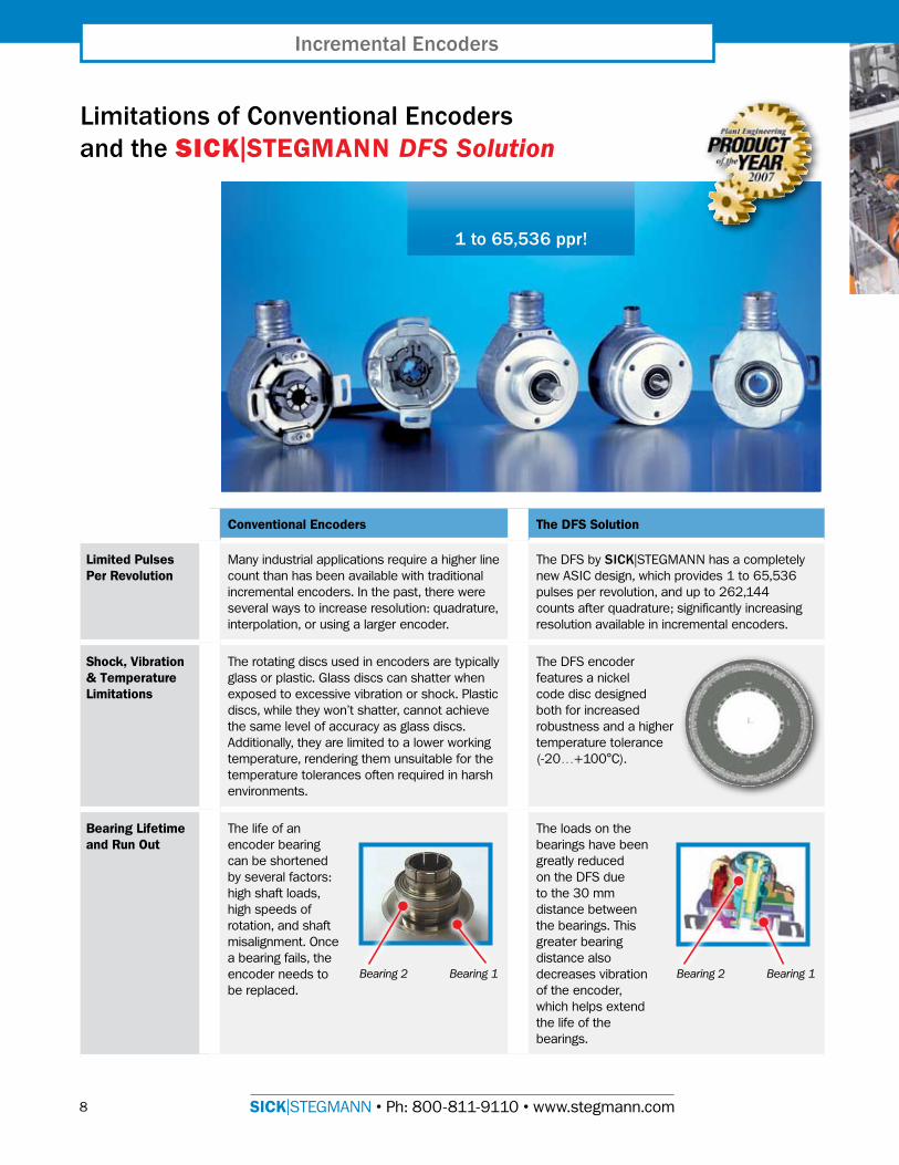
While rotary encoders are used in most applications without incident, there are inherent limitations in current encoder designs. The new DFS encoder by SICK|STEGMANN addresses these limitations with all new technology.
3RoHS2002/95/EC
3RoHS2002/95/EC
3RoHS2002/95/EC
8 SICK|STEGMANN • Ph: 800-8��-9��0 • www.stegmann.com
Conventional Encoders The DFS Solution
Limited Pulses Per Revolution
Many industrial applications require a higher line count than has been available with traditional incremental encoders. In the past, there were several ways to increase resolution: quadrature, interpolation, or using a larger encoder.
The DFS by SICK|STEGMANN has a completely new ASIC design, which provides � to 65,536 pulses per revolution, and up to 262,�44 counts after quadrature; significantly increasing resolution available in incremental encoders.
Shock, Vibration & Temperature Limitations
The rotating discs used in encoders are typically glass or plastic. Glass discs can shatter when exposed to excessive vibration or shock. Plastic discs, while they won’t shatter, cannot achieve the same level of accuracy as glass discs. Additionally, they are limited to a lower working temperature, rendering them unsuitable for the temperature tolerances often required in harsh environments.
The DFS encoder features a nickel code disc designed both for increased robustness and a higher temperature tolerance (-20…+�00°C).
Bearing Lifetime and Run Out
The life of an encoder bearing can be shortened by several factors: high shaft loads, high speeds of rotation, and shaft misalignment. Once a bearing fails, the encoder needs to be replaced.
The loads on the bearings have been greatly reduced on the DFS due to the 30 mm distance between the bearings. This greater bearing distance also decreases vibration of the encoder, which helps extend the life of the bearings.
1to65,536ppr!
IncrementalEncoders
Bearing 2 Bearing 1 Bearing 2 Bearing 1
LimitationsofConventionalEncodersandtheSICK|STEGMANN DFS Solution

9SICK|STEGMANN • Ph: 800-8��-9��0 • www.stegmann.com
Conventional Encoders The DFS Solution
Programmability Typical encoders are shipped by the manufacturer with the customers’ desired line count, pulse and electrical interface preset and unchangeable. This means that if customers need several encoders with various line counts and/or electrical interfaces, they will need to have several encoders for backup in inventory.
The programmable versions of the DFS allow the user to program the encoder to the line count desired and reprogram it, as needed.
Additionally, zero set and electrical interface (to either TTL or HTL) can be programmed.
A simple programming tool connected to a PC with a USB cable is used for all programming functions.
Axial and Radial Cable Outlets
Currently, when users require cable outlets for their encoders, they have the choice of a radial or axial outlet. It is possible they will need encoders with both in the same environment requiring additional inventory. Also, if the cable is somehow damaged, the encoder has to be returned to the manufacturer who will repair the encoder by replacing the cable.
The DFS encoders are available with a pluggable outlet that can be used in either a radial or axial direction which requires less installation depth. Since it is detachable, if the cable is damaged, no repair is necessary by the manufacturer. The customer can simply order a new cable and plug it into the encoder. Various cable lengths and connectors at the end of the cable are also available.
3RoHS2002/95/EC
■ RoHS compliant
■ High frequency response
■ IP 65 protection class
■ Excellent concentricity
■ High shaft loading
■ High operating speed
■ Programmable versions come with diagnostic function that reads shaft position
OtherFeatures
oftheDFS
�0 SICK|STEGMANN • Ph: 800-8��-9��0 • www.stegmann.com
Accessoriessee www.stegmann.com
■ Adapters■ Cable Assemblies■ Collets ■ Couplings■ Connection Systems■ Programming Tools■ Wire Draw Mechanism
Accessories
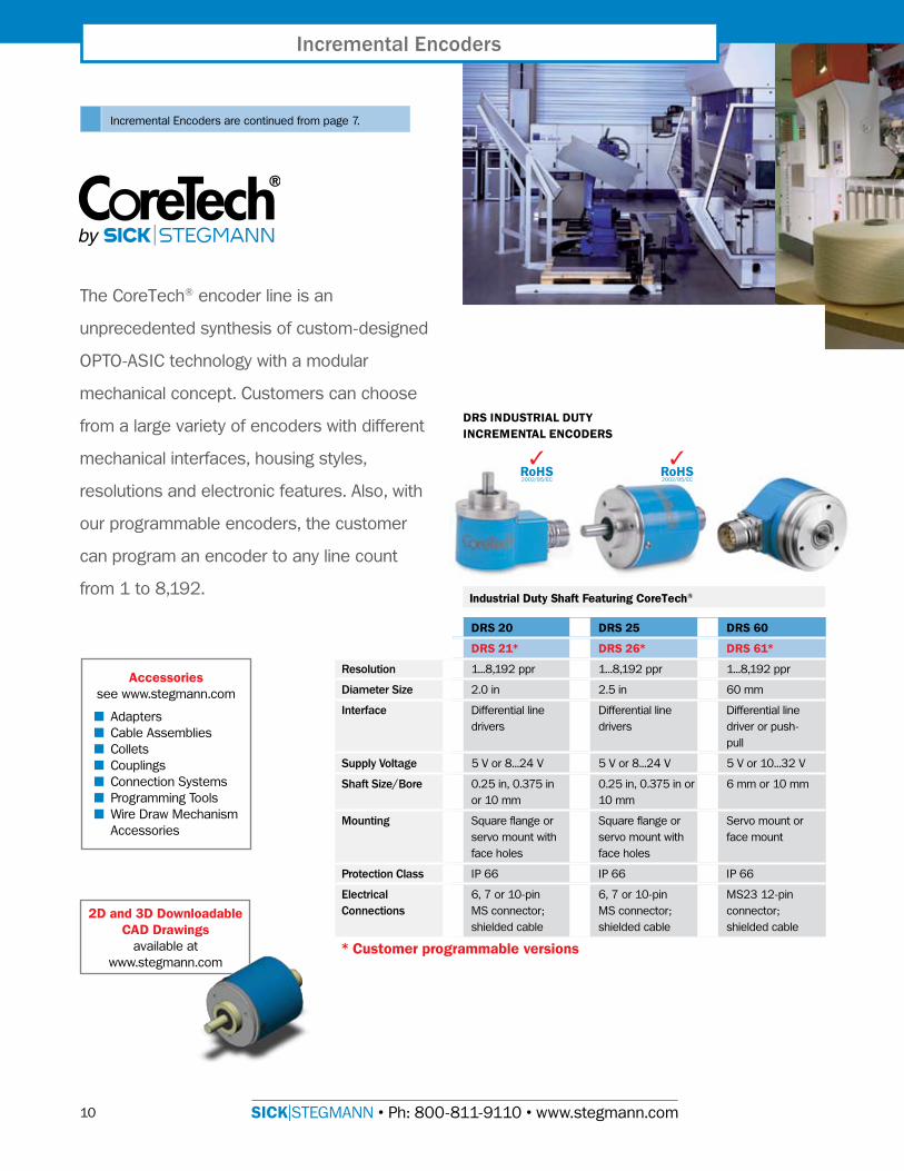
The CoreTech® encoder line is an
unprecedented synthesis of custom-designed
OPTO-ASIC technology with a modular
mechanical concept. Customers can choose
from a large variety of encoders with different
mechanical interfaces, housing styles,
resolutions and electronic features. Also, with
our programmable encoders, the customer
can program an encoder to any line count
from � to 8,�92.
DRS 20 DRS 25 DRS 60
DRS 21* DRS 26* DRS 61*
Resolution �...8,�92 ppr �...8,�92 ppr �...8,�92 ppr
DiameterSize 2.0 in 2.5 in 60 mm
Interface Differential line drivers
Differential line drivers
Differential line driver or push-pull
SupplyVoltage 5 V or 8...24 V 5 V or 8...24 V 5 V or �0...32 V
ShaftSize/Bore 0.25 in, 0.375 in or �0 mm
0.25 in, 0.375 in or �0 mm
6 mm or �0 mm
Mounting Square flange or servo mount with face holes
Square flange or servo mount with face holes
Servo mount or face mount
ProtectionClass IP 66 IP 66 IP 66
ElectricalConnections
6, 7 or �0-pin MS connector; shielded cable
6, 7 or �0-pin MS connector; shielded cable
MS23 �2-pin connector; shielded cable
* Customer programmable versions
IncrementalEncoders
2D and 3D Downloadable CAD Drawings
available at www.stegmann.com
Industrial Duty Shaft Featuring CoreTech®
DRS INDUSTRIAL DUTY INCREMENTAL ENCODERS
Incremental Encoders are continued from page 7.
3RoHS2002/95/EC
3RoHS2002/95/EC

��SICK|STEGMANN • Ph: 800-8��-9��0 • www.stegmann.com
Incremental Encoders are continued on the next page.
SICK|STEGMANN incremental encoders are used in a wide range of demanding industrial applications.
DGS 20 DGS 25 DGS 60
Resolution �...3,000 ppr �...5,000 ppr �00...�0,000 ppr
DiameterSize 2.0 in 2.5 in 60 mm
Interface Differential line drivers or open collector
Differential line drivers or open collector
TTL/RS 422, HTL push-pull
SupplyVoltage 5 V or 8...24 V 5 V or 8...24 V 5 V or �0...32 V
ShaftSize/Bore 0.25 in, 0.375 in or �0 mm
0.25 in, 0.375 in or �0 mm
6 mm or �0 mm
Mounting Square flange or servo mount with face holes
Square flange or servo mount with face holes
Servo mount or face mount
ProtectionClass IP 66 IP 66 IP 67
ElectricalConnections
6, 7 or �0-pin MS connector; shielded cable
6, 7 or �0-pin MS connector; shielded cable
MS23 �2-pin connector; shielded cable
Heavy Duty Shaft
DGS HEAVY DUTY INCREMENTAL ENCODERS
3RoHS2002/95/EC
3RoHS2002/95/EC
�2 SICK|STEGMANN • Ph: 800-8��-9��0 • www.stegmann.com
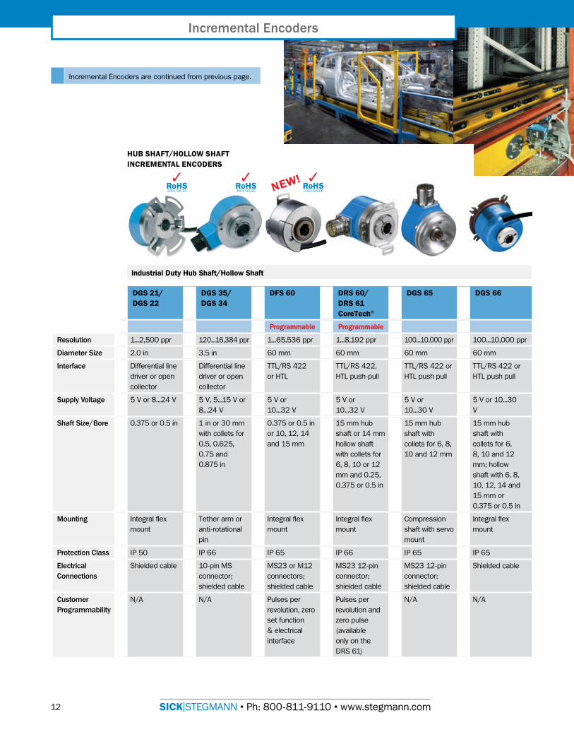
Incremental Encoders are continued from previous page.
Industrial Duty Hub Shaft/Hollow Shaft
HUB SHAFT/HOLLOW SHAFT INCREMENTAL ENCODERS
NEW!
DGS 21/DGS 22
DGS 35/DGS 34
DFS 60 DRS 60/DRS 61 CoreTech®
DGS 65 DGS 66
Programmable Programmable
Resolution �...2,500 ppr �20...�6,384 ppr �...65,536 ppr �...8,�92 ppr �00...�0,000 ppr �00...�0,000 ppr
DiameterSize 2.0 in 3.5 in 60 mm 60 mm 60 mm 60 mm
Interface Differential line driver or open collector
Differential line driver or open collector
TTL/RS 422 or HTL
TTL/RS 422, HTL push-pull
TTL/RS 422 or HTL push pull
TTL/RS 422 or HTL push pull
SupplyVoltage 5 V or 8...24 V 5 V, 5...�5 V or 8...24 V
5 V or �0...32 V
5 V or �0...32 V
5 V or �0...30 V
5 V or �0...30 V
ShaftSize/Bore 0.375 or 0.5 in � in or 30 mm with collets for 0.5, 0.625, 0.75 and 0.875 in
0.375 or 0.5 in or �0, �2, �4 and �5 mm
�5 mm hub shaft or �4 mm hollow shaft with collets for 6, 8, �0 or �2 mm and 0.25, 0.375 or 0.5 in
�5 mm hub shaft with collets for 6, 8, �0 and �2 mm
�5 mm hub shaft with collets for 6, 8, �0 and �2 mm; hollow shaft with 6, 8, �0, �2, �4 and �5 mm or 0.375 or 0.5 in
Mounting Integral flex mount
Tether arm or anti-rotational pin
Integral flex mount
Integral flex mount
Compression shaft with servo mount
Integral flex mount
ProtectionClass IP 50 IP 66 IP 65 IP 66 IP 65 IP 65
ElectricalConnections
Shielded cable �0-pin MS connector; shielded cable
MS23 or M�2 connectors; shielded cable
MS23 �2-pin connector; shielded cable
MS23 �2-pin connector; shielded cable
Shielded cable
CustomerProgrammability
N/A N/A Pulses per revolution, zero set function & electrical interface
Pulses per revolution and zero pulse (available only on the DRS 6�)
N/A N/A
IncrementalEncoders
3RoHS2002/95/EC
3RoHS2002/95/EC
3RoHS2002/95/EC
�3SICK|STEGMANN • Ph: 800-8��-9��0 • www.stegmann.com
Accessoriessee www.stegmann.com
■ Adapters■ Cable Assemblies■ Collets ■ Couplings■ Connection Systems■ Programming Tools■ Wire Draw Mechanism
Accessories
2D and 3D Downloadable CAD Drawings
available at www.stegmann.com
LD 20 DKS 40 HD 32 HD 52
Resolution �0...2,500 ppr �...�,024 ppr �0...2,500 ppr �0...2,500 ppr
DiameterSize 2.0 in 40 mm 3.25 in cube 3.25 in x 3.25 in x 5.7 in long
Interface Differential line driver or open collector
TTL/RS 422, HTL push-pull or open collector
Differential line driver or open collector
Differential line driver or open collector
SupplyVoltage 5 V or 8...24 V 5 V or �0...30 V 5 V or 8...24 V 5 V or 8...24 V
ShaftSize/Bore 0.25 in 8 mm 0.375 in single or double ended
0.375 in or 0.625 in
Mounting Face mount Face mount flange, servo flange
Foot mount or face mount
Face mount
ProtectionClass IP 50 IP 64 IP 65 IP 66
ElectricalConnections
Shielded cable Shielded cable 6 or �0-pin MS connector
7 or �4-pin MS connector
Special PurposeLight Duty Shaft
DKV 60 Measuring Wheel
(See page 19)
LIGHT DUTY AND SPECIAL PURPOSE INCREMENTAL ENCODERS
3RoHS2002/95/EC
3RoHS2002/95/EC
3RoHS2002/95/EC
�4 SICK|STEGMANN • Ph: 800-8��-9��0 • www.stegmann.com
Accessoriessee www.stegmann.com
■ Adapters■ Cable Assemblies■ Collets ■ Couplings■ Connection Systems■ Programming Tools■ Wire Draw Mechanism
Accessories
AbsoluteEncodersSelectionGuide
ARS 20 ARS 25 ARS 60
(CoreTech) (CoreTech) (CoreTech)
Resolution 2...32,768 cpr 2...32,768 cpr 2...32,768 cpr
DiameterSize 2.0 in 2.5 in 60 mm
Interface SSI, Push-pull, Open collector, TTL
SSI, Push-pull, Open collector, TTL
SSI or parallel
SupplyVoltage �0...30 V, 8...24 V, 5 V
�0...30 V, 8...24 V, 5 V
�0...32 V
OutputCodeFormats
Gray, Gray Excess, Natural Binary, Binary Coded Decimal
Gray, Gray Excess, Natural Binary, Binary Coded Decimal
Gray, Gray Excess, Natural Binary, Binary Coded Decimal
Bore/ShaftSizeandMounting
0.25 in, 0.375 in, �0 mm; Square flange, servo mount with face holes
0.25 in, 0.375 in, �0 mm; Square flange, servo mount with face holes
6 mm with servo mount or �0 mm with face mount; �5 mm hub shaft or �4 mm hollow shaft with integral flex mount and collets for 6, 8, �0 or �2 mm and 0.25, 0.375 or 0.5 in
ProtectionClass IP 66 IP 66 IP 66
ElectricalConnections
�7, �9 or 23-pin MS connector; MS23 �2-pin connector; shielded cable
�7, �9 or 23-pin MS connector; MS23 �2-pin connector; shielded cable
MS23 �2-pin connector; shielded cable
CoreTech® Single-Turn Encoders
AbsoluteEncoders
The CoreTech® concept uses a
minimum number of components to
achieve maximum variety: A proprietary
hybrid OPTO-ASIC, designed by
SICK|STEGMANN, and a small, unique
disk with a barcode track.
2D and 3D Downloadable CAD Drawings
available at www.stegmann.com
ARS INDUSTRIAL DUTY CORETECH® SINGLE-TURN ENCODERS
3RoHS2002/95/EC
3RoHS2002/95/EC

�5SICK|STEGMANN • Ph: 800-8��-9��0 • www.stegmann.com
ATM 90-A ATM 90-P ATM 60-A ATM 60-D ATM 60-C ATM 60-P
(SSI) (Profibus) (SSI) (DeviceNet) (CANopen) (Profibus)
Resolution �3 bits per turn x 8,�92 turns (26 bit max), programmable
�3 bits per turn x 8,�92 turns (26 bit max), programmable
�3 bits per turn x 8,�92 turns (26 bit max), programmable
�3 bits per turn x 8,�92 turns (26 bit max), programmable
�3 bits per turn x 8,�92 turns (26 bit max), programmable
�3 bits per turn x 8,�92 turns (26 bit max), programmable
DiameterSize 93 mm 93 mm 60 mm 60 mm 60 mm 60 mm
Interface SSI, RS 422 RS 485 bus coupling to Profibus DP specifications
SSI DeviceNet specification release 2.0
Communication Profile DS 30� V4.0; Device Profile DSP 406 V2.0
RS 485 bus coupling to Profibus DP specifications
SupplyVoltage �0...32 V �0...32 V �0...32 V �0...32 V �0...32 V �0...32 V
OutputCodeFormats
Gray or Natural Binary
Gray or Natural Binary
Gray or Natural Binary
Bore/ShaftSizeandMounting
�2 mm, �6 mm or 0.5 in hollow shaft with anti-rotational pin mount
�2 mm, �6 mm or 0.5 in hollow shaft with anti-rotational pin mount
6 mm with servo mount or �0 mm with face mount; �5 mm hub shaft with integral flex mount and collets for 6, 8, �0 or �2 mm and 0.25, 0.375 or 0.5 in
6 mm with servo mount or �0 mm with face mount; �5 mm hub shaft with integral flex mount and collets for 6, 8, �0 or �2 mm and 0.25, 0.375 or 0.5 in
6 mm with servo mount or �0 mm with face mount; �5 mm hub shaft with integral flex mount and collets for 6, 8, �0 or �2 mm and 0.25, 0.375 or 0.5 in
6 mm with servo mount or �0 mm with face mount; �5 mm hub shaft with integral flex mount and collets for 6, 8, �0 or �2 mm and 0.25, 0.375 or 0.5 in
ProtectionClass IP 65 IP 65 IP 67 IP 67 IP67 IP 67
ElectricalConnections
MS23 �2-pin connector
Three M�4 7-pin connectors or three PG cable glands
MS23 �2-pin connector; shielded cable
Separate bus connector with single or dual 5-pin micro connectors, or single or dual PG gland
Separate bus connector with one, two or three PG cable glands
Separate bus connector
Absolute Multi-Turn Encoders
ATM HEAVY DUTY ABSOLUTE MULTI-TURN ENCODERS
�6 SICK|STEGMANN • Ph: 800-8��-9��0 • www.stegmann.com
L 230 Magnetic (Lincoder®)The Lincoder® system supplied by SICK|STEGMANN consists of a magnetic tape and sensor head. The magnetic tape provides the scale for measuring systems up to 40 meters long. The absolute information is magnetized onto the tape in a �2-bit sequential code. This position information is enhanced by interpolation of sine/cosine signals provided by an additional incremental track that is magnetized on the tape. The magnetic tape is laminated onto a ferromagnetic steel strip, which is used both as a magnetic return path and a dimensionally stable mounting aid. The magnetic tape is supplied with an adhesive back for mounting by the user.
A non-contact magnetic sensor with integrated electronics is mounted to the apparatus whose position is to be measured. As the sensor moves over the measuring tape, its position is output with a resolution as low as � µm over a �6 meter range, or �0 µm over a 40 meter range. Position data is output via real-time compensated SSI (Synchronous Serial Interface), HIPERFACE®, or RS 485. The Lincoder is also programmable via RS 485, and a number of parameters such as offset, resolution and start points can be configured by the user.
LinearEncodersandWireDrawSystems
Use linear encoders to measure incremental or absolute position along any axis.
SICK|STEGMANN linear encoders can be used in applications up to �.7 kilometers long!
LengthMeasuringSystems
KH 53 (Pomux®) and Advanced KH 53 Long Distance Linear EncodersThis style of encoder is unique to SICK|STEGMANN and allows absolute measurement of up to �.7 kilometers! The KH 53 consists of two basic components: Omega Profile sections and the sensor head. Each Omega Profile section contains a number of powerful permanent magnets. The separation between each magnet is unique and never repeated. These unique separations build up a code over the complete measurement path. In a working system, several Omega Profile sections are placed end to end along the complete measurement path. The total length of the system determines the number of profiles required. Each profile section is labeled with an identification number indicating the order in which the sections should be mounted.
The sensor head moves over the Omega Profile sections without contact, and produces absolute positional data. The KH 53 allows a generous vertical tolerance of ±�0 mm around a 25 mm nominal value, and a horizontal tolerance of ±�0 mm around the centerline. The output is available in SSI, and Profibus. Other networks can be realized using commercially available I/O modules.
In addition, this modular system offers several benefits to the user. If the measurement length of the system needs to increase in the future, the user simply needs to mount the extra profiles required. If the Omega Profile become damaged, only the damaged sections need to be replaced.
The Advanced KH 53 has 54 m or 548 m measuring lengths, a positional/mounting tolerance to ±20 mm, and an operating temperature of -30 to 70°C. The Advanced KH 53 has the added advantage of requiring less installation time than the standard KH 53.
The new DKV 60 Measuring Wheel Encoder is designed specifically for use with conveyor systems (see page �9).

�7SICK|STEGMANN • Ph: 800-8��-9��0 • www.stegmann.com
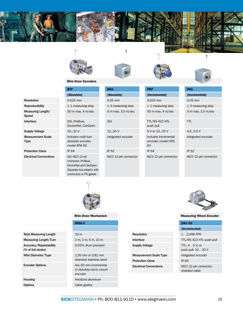
BTF/PRF Wire-Draw EncodersWire draw encoders are linear-to-rotational, industrial motion conversion modules, coupled with encoder feedback, to provide cost-effective linear position measurement solutions that precisely fit your requirements. These systems are housed in rugged industrial enclosures, and contain a stainless steel or thermoplastic composite cable wound on a precise, constant-diameter spool. The cable is attached to the apparatus whose position is being measured, and is extended and retracted as the apparatus moves. A spring on the spool maintains cable tension. Position feedback is provided by a standard incremental or absolute rotary shaft encoder.
These position transducers allow very flexible measuring paths, since the cable can be guided around obstacles using pulleys, etc. The heavy-duty enclosure of the encoder and spool housing provide excellent protection against contaminants, shock and other abuses.
Length measuring systems by SICK|STEGMANN are flexible enough for almost any orientation or measuring path.
BKS/PKS Wire-Draw EncodersIn these compact wire draw encoders, the encoder is integrated into the wire draw mechanism to minimize the size of the unit.
The number of drum rotations, which is proportional to the length being measured, is counted by an encoder and converted to a standard encoder output signal. This provides high-resolution position or distance information for linear measurement paths, even under difficult mounting conditions.
Precise linear guidance, as required for other length measurement systems, is not necessary.
The choice between absolute and incremental wire draw encoders manufactured by SICK|STEGMANN enables made-to-measure solutions for many applications: SSI interface for absolute wire draw encoders, TTL interface for incremental wire draw encoders. Both interfaces are common in automation technology and meet its exacting requirements.
The measuring lengths up to 5 m cover most of the possible applications, for example in:
Presses, punching and injection machines, storage technology, wood and sheet metal processing machines, constructionmachinery, medical technology and many other industries.
�8 SICK|STEGMANN • Ph: 800-8��-9��0 • www.stegmann.com
LengthMeasuringSystems
LinearEncodersandWireDrawSystemsSelectionGuide
You can rely on SICK|STEGMANN encoders to keep your operation up and running.
L 230 Lincoder®
Resolution For SSI: � micron with calibrated tape, �0 micron with uncalibrated tape; For Hiperface: �56.25 micron
Reproducibility ± �0 micron
MeasuringLength/Speed
40 m max, 6 m/sec
Interface SSI; Hiperface
SupplyVoltage SSI: �0...32 V; Hiperface: 7...�2 V
MeasurementScaleType
Stationary magnetic tape with or without glue
ProtectionClass IP 65
ElectricalConnections M23 �2-pin connector
KH 53 Pomux® KH 53 Pomux®
Advanced
Resolution 0.� mm 0.� mm
Reproducibility ± 0.3 mm ± �.00 mm
AccuracyWithinaMeasuringElement
± �000 + ME (Tu -25°C) TK micron
± 2000 + ME (Tu -25°C) TK micron
PositionalTolerance ± �0 mm ± 20 mm
OperatingTemperature -20° to 60°C -30° to 70°C
MeasuringLength/Speed
�700 m max, 6.6 m/sec
54 m or 548 m, 6.6 m/sec
Interface SSI, Profibus DP (07hex), Class 2
SSI, Profibus DP (07hex), Class 2
SupplyVoltage �0...32 V �0...32 V
MeasurementScaleType
Stationary Omega profiles with embedded magnets
Stationary Omega profiles with embedded magnets
ProtectionClass IP 66 IP 66
ElectricalConnections SSI: M23 �2-pin connectors; Profibus: 3 PG cable glands
SSI: M23 �2-pin connectors; Profibus: 3 PG cable glands
Linear Absolute Encoders
2D and 3D Downloadable CAD Drawings
available at www.stegmann.com
Accessoriessee www.stegmann.com
■ Adapters■ Cable Assemblies■ Collets ■ Couplings■ Connection Systems■ Programming Tools■ Wire Draw Mechanism
Accessories
�9SICK|STEGMANN • Ph: 800-8��-9��0 • www.stegmann.com
DKV 60
(Incremental)
Resolution �…2,048 PPR
Interface TTL/RS 422 HTL push-pull
SupplyVoltage TTL: 4…5 V; orpush pull: �0…30 V
MeasurementScaleType Integrated encoder
ProtectionClass IP 65
ElectricalConnections M23 �2-pin connector; shielded cable
MRA-F
TotalMeasuringLength �0 m
MeasuringLength/Turn 2 m, 3 m, 5 m, �0 m
Accuracy/Repeatability(%offullstroke)
0.05% drum precision
WireDiameter/Type �.35 mm or 0.8� mm stranded stainless steel
EncoderOptions Any 60 mm incremental or absolute servo mount encoder
Housing Anodized aluminum
Options Cable guides
BTF BKS PRF PKS
(Absolute) (Absolute) (Incremental) (Incremental)
Resolution 0.025 mm 0.05 mm 0.025 mm 0.05 mm
Reproducibility ± � measuring step ± 3 measuring step ± � measuring step ± 3 measuring step
MeasuringLength/Speed
50 m max, 4 m/sec 5 m max, 3.5 m/sec 50 m max, 4 m/sec 5 m max, 3.5 m/sec
Interface SSI, Profibus, DeviceNet, CanOpen
SSI TTL/RS 422 HTL push-pull
TTL
SupplyVoltage �0...32 V �2...30 V 5 V or �0...32 V 4.5...5.5 V
MeasurementScaleType
Includes multi-turn absolute encoder, model ATM 60
Integrated encoder Includes incremental encoder, model DRS 60
Integrated encoder
ProtectionClass IP 64 IP 52 IP 64 IP 52
ElectricalConnections SSI: M23 �2-pin connector; Profibus, DeviceNet and CanOpen: Separate bus adaptor with connectors or PG glands
M23 �2-pin connector M23 �2-pin connector M23 �2-pin connector
Wire-Draw Encoders
Wire-Draw Mechanism Measuring Wheel Encoder

20 SICK|STEGMANN • Ph: 800-8��-9��0 • www.stegmann.com
HIPERFACE®Adapters
Motor Feedback Meets Factory Automation
The HIPERFACE® interface adapter modules allow users to connect single-turn or multi-turn encoders that have the HIPERFACE® interface to systems using other communication protocols, opening up a variety of application options in all areas of automation technology.
Encoders with the HIPERFACE® interface are being designed as Motor Feedback systems for drive technology. This creates an extremely compact design.
In addition to encoders integrated into drives, stand-alone designs are also available. In conjunction with a HIPERFACE® interface adapter module, encoders can be used in a broad range of applications in automation technology. For example where:
■ High encoder resolutions are necessary — up to 262,000 counts per turn can be generated easily in the interface adapter via interpolation of the HIPERFACE® encoder signals.
■ Space is very limited.
■ Environmental conditions such as dirt, temperature, shock and/or vibration must be isolated from the electronics.
■ Customer-specific encoder flange and housing options are required, which must be realized quickly and at a low-cost.
At the output of the interface adapter modules, SSI, Profibus, DeviceNet and CANopen are available, using standard M�2 connectors. These interfaces fulfill the high requirements of automation technology. Further, the diverse range of possible combinations of interface adapter modules and encoders provides a high level of flexibility, coupled with low part replacement and stocking costs.
Protection Class Use with these HIPERFACE® Motor Feedback encoders*
HIPERFACE®SSIAdapter IP 64 SRS, SCK, SKS, SEK, SRM, SCL, SKM, L230
HIPERFACE®ProfibusAdapter IP 64 SRS, SCK, SKS, SEK, SRM, SCL, SKM, L230, XKS
HIPERFACE®DeviceNetAdapter IP 64 SRS, SCK, SKS, SEK, SRM, SCL, SKM, L230, XKS
HIPERFACE®CanopenAdapter IP 64 SRS, SCK, SKS, SEK, SRM, SCL, SKM, L230, XKS
*SICK|STEGMANN Motor Feedback Encoders are available on our Web Site at www.stegmann.com or in our Motor Feedback Systems Brochure.
HIPERFACEInterfaceAdapterModule
Out
In
ToPLC
®
Encoder withHIPERFACEInterface
®
HIPERFACE®Adapters
2�SICK|STEGMANN • Ph: 800-8��-9��0 • www.stegmann.com
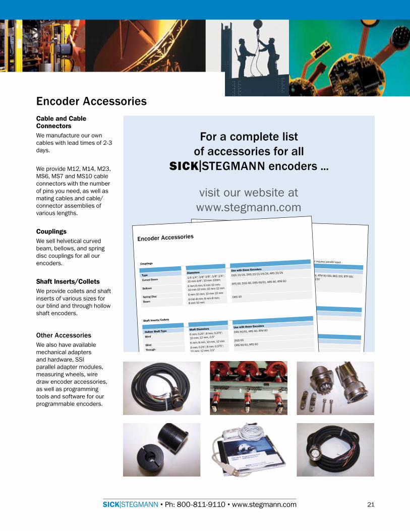
EncoderAccessoriesCable and Cable ConnectorsWe manufacture our own cables with lead times of 2-3 days.
We provide M�2, M�4, M23, MS6, MS7 and MS�0 cable connectors with the number of pins you need, as well as mating cables and cable/connector assemblies of various lengths.
CouplingsWe sell helvetical curved beam, bellows, and spring disc couplings for all our encoders.
Shaft Inserts/ColletsWe provide collets and shaft inserts of various sizes for our blind and through hollow shaft encoders.
OtherAccessoriesWe also have available mechanical adapters and hardware, SSI parallel adapter modules, measuring wheels, wire draw encoder accessories, as well as programming tools and software for our programmable encoders.
Foracompletelistofaccessoriesforall
SICK|STEGMANNencoders...
Measuring Wheel
Programming Tools and Software
SSI Parallel Adapter Modules
Wire Draw Encoder Accessories
Profibus Link Adapter
Housing Programmable Use with these EncodersNohousingorfrontplate no ARS 20/25/60, ATM 60-SSI, ATM 90-SSI, BKS-SSI, BTF-SSI, KH 53, KH 53 Advanced L 230Withplastichousingorfrontplate noNohousingorfrontplate yesWithfrontplate yes
An SSI parallel adapter will allow you to connect your encoder with SSI interface into any PLC or drive that requires parallel input.
Description Cable Glands Use with these EncodersKH53LinkAdapter 3 cable glands KH 53, KH 53 Advanced
Material Shaft Diameter/Circumference Use with these EncodersNeoprene 3/8” / �2” DGS 20/25, DRS 20/2�/25/26Plastic(Hytrel),wheelplastic �0 mm / 0.2 m or 0.5 m DFS 60, DGS 60, DRS 60/6�
Description Lengths Use with these EncodersWireguidingrollerforwiredrawmechanism
2, 5, �0, 20, 30 m BTF, PRF, MRA-F
Drawmechanism-assemblyfittings(clamps,screws,couplingandsealingrings)
N/A
MRA-Fwiredrawmechanismwithoutencoder
2, 5, �0, 20, 30, 50 m BTF, MRA-F
DescriptionUse with these EncodersSoftwaretoolforcustomerprogrammableCoreTech®Encoders DRS 2�/26/6�ProgrammingtoolforSSIinterfaceATM 60-SSI, ATM 90-SSI, KH 53, KH 53 AdvancedProgrammingtoolforserialparalleladapter ATM 60-SSI, ATM 90-SSI, KH 53, KH 53 Advanced, BTF, L 230ProgrammingtoolforL230L 230ProgrammingtoolandsoftwareforDFS60 DFS 60
Couplings
EncoderAccessories
Shaft Inserts/Collets
Mechanical Adapters / Mounting Hardware
TypeDiameters
Use with these Encoders
CurvedBeam�/4-�/4”; 3/8”-3/8”; 3/8”-�/4”;
�0 mm-3/8”; �0 mm-�0mm
DGS 20/25, DRS 20/2�/25/26, ARS 20/25
Bellows6 mm-6 mm; 6 mm-�0 mm;
�0 mm-�0 mm; �0 mm-�2 mm
DFS 60, DGS 60, DRS 60/6�, ARS 60, ATM 60
Spring-Disc6 mm-�0 mm; �0 mm-�0 mm
Beam6 mm-8 mm; 8 mm-8 mm;
8 mm-�0 mm
DKS 40
Hollow Shaft Type Shaft Diameters Use with these Encoders
Blind6 mm; 0.25”; 8 mm; 0.375”;
�0 mm; �2 mm, .0.5”
DRS 60/6�, ARS 60, ATM 60
Blind6 mm; 8 mm, �0 mm, �2 mm DGS 65
Through6 mm; 0.25”; 8 mm; 0.375”;
�0 mm; �2 mm; 0.5”
DRS 60/6�, ARS 60
Through6 mm; 8 mm, �0 mm, �2 mm,
0.5”, �4 mm, �5 mm
DGS 66
Blind&Through �/2”; 5/8”; 3/4”; 7/8” DGS 34/35
TypeDescription
Use with these Encoders
AdapterPlates Use to adapt an encoder with
one mounting style to a different
size, or style mount.
DFS 60, DGS 60, DRS 60/6�, ARS 60, ATM 60
ServoClamps Use for mounting encoders with
servo flanges.
DFS 60, DGS 60/65, DRS 60/6�, DKS 40, ARS 60, ATM 60
MountingBell Provides space between encoder
and machine surface, such as for
installing a coupling.
DFS 60, DGS 60, DKS 40, DRS 60/6�, ARS 60, ATM 60
MountingAngle Angle bracket for mounting face
mount encoders.
DFS 60, DGS 60/65/66, DRS 60/6�, DKV 40, ARS 60, ATM 60
SpacerSupport For elevation of KH 53 measuring
elements.
KH 53, KH 53 Advanced
FasteningClamp For mounting KH 53 measuring
elements.
KH 53, KH 53 Advanced
BearingBlock For very large radial and axial
shaft loads
DFS 60
visit our website at www.stegmann.com
SICK|STEGMANN • Ph: 800-8��-9��0 • www.stegmann.com
7028102
SICK STEGMANN,INC.7496 Webster Street, Dayton, OH 454�4Ph: 800-8��-9��0 or 937-454-�956 • Fax: 937-454-�955www.stegmann.com
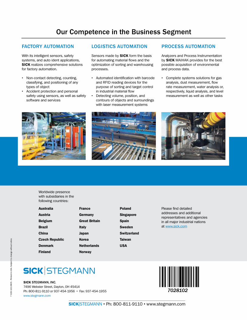
FACTORYAUTOMATION
With its intelligent sensors, safety systems, and auto ident applications, SICK realizes comprehensive solutions for factory automation.
• Non-contact detecting, counting, classifying, and positioning of any types of object
• Accident protection and personal safety using sensors, as well as safety software and services
LOGISTICSAUTOMATION
Sensors made by SICK form the basis for automating material flows and the optimization of sorting and warehousing processes.
• Automated identification with barcode and RFID reading devices for the purpose of sorting and target control in industrial material flow
• Detecting volume, position, and contours of objects and surroundings with laser measurement systems
PROCESSAUTOMATION
Analyzers and Process Instrumentation by SICK MAIHAK provides for the best possible acquisition of environmental and process data.
• Complete systems solutions for gas analysis, dust measurement, flow rate measurement, water analysis or, respectively, liquid analysis, and level measurement as well as other tasks
OurCompetenceintheBusinessSegment
Worldwide presence with subsidiaries in the following countries:
France
Germany
Great Britain
Italy
Japan
Korea
Netherlands
Norway
Australia
Austria
Belgium
Brazil
China
Czech Republic
Denmark
Finland
Poland
Singapore
Spain
Sweden
Switzerland
Taiwan
USA
Please find detailed addresses and additional representatives and agencies in all major industrial nations at www.sick.com
7 0
28
�0
2.0
80
5 .
Prin
ted
in U
SA
. Sub
ject
to c
hang
e w
ithou
t not
ice.


![Core Software Technologies [CoreTech]coretechit.com/CoreTech_Company_Profile1.0.pdfCore Software Technologies [CoreTech] Company Profile Core Software Technologies Company Profile](https://static.cupdf.com/doc/110x72/5aa333167f8b9a1f6d8e45d0/core-software-technologies-coretech-software-technologies-coretech-company-profile.jpg)


