g..b/esstmortoj.mjre/ttsptth ERJ
Engineering Research Journal
Faculty of Engineering
Menoufia University
ISSN: 1110-1180
DOI: 10.21608/erjm.2021.42713.1041
ERJ, PART 1, Mach. Eng., Vol. 44, No. 1, January 2021, pp. 11-20 11
Effect of Inlet and Geometrical Parameters on the Melting
of PCM Capsules of Elliptical Cross Section
Mohamed A. Sultan1*
, Hesham M. Mustafa2, Emad A. El-Negiry
3
and Ali M. El-Boz3
1 Mechanical. Eng. Dept, Future Institute of Engineering and Technology, Talkha, Egypt. 2Mechanical Eng. Dept., Higher Technological Institute, 10
th of Ramadan
3Mechanical Power Eng. Dept., Faculty of Eng, Mansoura University, Mansoura, Egypt.
*(Corresponding author:sultanaan@gmail .com)
Asharqia, Egypt.
ABSTRACT
This paper focuses on the melting of phase change material capsulated in the elliptical cross-section
horizontal cylinder under convective boundary conditions. Different parameters are discussed, namely,
the HTF inlet temperature and velocity and the axes ratio of the capsule cross-section. The effect of HTF
inlet temperature, inlet velocity, and the capsule axes ratio was studied using the CFD software FLUENT
6.3.26. A comparison between the numerical and experimental results was made for the system. The
experimental results matched well with the heat transfer model. It is shown that the inlet temperature of
the heat transfer fluid (HTF) has a great effect on the process of paraffin wax melting. The increase of
HTF inlet temperature increases the PCM liquid fraction at constant charging time and decreases at the
same time the total time of the capsulated paraffin wax melting. The geometry of the capsule cross-
section represented by its axes ratio has a sensible effect on the process of paraffin wax melting.
Increasing the axes ratio of the capsule, i.e. elongated the capsule in the perpendicular direction of flow
increasing the PCM liquid fraction at constant charging time and decreases the total time of the
capsulated paraffin wax melting. The increase of HTF inlet velocity has a weak effect on the process of
paraffin wax melting in the inlet velocity range 0.003-0.012 m/s.
Keywords: Encapsulated, PCM, Heat transfer, Melting time, Axes ratio, Elliptical cross-section.
1. Introduction
Because of their thermal properties, phase
change materials are extremely utilized in thermal
systems. These materials have the ability to absorb
and release great amounts of heat with a slight
temperature change and density (has a high rate of
fusion). This heat is called latent heat of fusion of
phase change material (PCM). PCM is utilized in
many disciplines for latent heat storage; for
example, solar based thermal energy [1] in
buildings heating [2], spacecraft heat, and pumps
[3]. Because of its low thermal conductivity, the
usage of PCM has been limited [4].
Research has been carried out on phase change
materials with an implementation in thermal
systems. Enclosures with diverse shapes and sizes
had been investigated experimentally and
analytically. Numerous researches were carried out
to examine the melting and solidification of PCM
filled inside cylindrical, tubular, rectangular and
spherical cross-section capsules are epitomized in
the next paragraphs.
It is reported that the capsules geometry had a
great impact on the heat transfer features. Wei et al.
[5] carried out experimental and numerical studies
on a number of geometries of PCMs capsules, such
as, plate, sphere, tube and cylinder to develop the
rate of heat transfer. It was concluded that the
spherical capsule usage increased the heat transfer
amount. The rate of heat transfer for other shapes
increased in the sequence of tube, plate and
cylinder. Siva et al. [6] analyzed different shapes of
constant volume filled with PCM, and reported that
the cylinder had an encapsulation best than the
sphere. The cylinder surface area was 38% higher
than that for the sphere, which caused 47%
decrease in the solidification total time. To
decrease the solidification time the cylinder
selected dimensions were such that the radius is not
large enough. So, the shape selection of the
capsules played a great effect on the thermal
energy storage (TES) systems.
In spite of a lot of numerical and experimental
searches were dedicated to a PCM melting for
various geometric shapes in convection field, a
specific interest was disposed to the melting

Mohamed A. Sultan, Hesham M. Mustafa, Emad A. El-Negiry and Ali M. El-Boz “Effect of Inlet
and Geometrical Parameters on the Meltingof PCM Capsules of Elliptical Cross Section”
ERJ, Menoufia University, Vol. 44, No. 1, January 2021 12
process inside a cylinder, placed in horizontal
position as a TES model [7-9]. Based on the
Boussinesq approximation, many analytical and
numerical investigations were accomplished as
attempts for melting phenomenon modeling in a
horizontal cylinder of circular cross section [10–
14]. Saitoh and Hirose [10] offered experiments to
indicate the concaved border at the lower portion of
liquid/solid border over melting. Experimental
studies were conducted by Rieger et al. [11], Ho
and Viskanta [12], and Yoo and Ro [13], on the
development of a liquid-solid interface through the
melting of PCM contained inside a horizontal
cylinder. A concaved liquid-solid interface was
shown experimentally and numerically at the lower
portion of solid phase. The unconstrained PCM
melting inside a horizontal cylinder under
isothermal condition was studied numerically by
Prasad and Sengupta [14]. The study estimated the
temporally, irregular shape of the solid-liquid
boundary. The study proved that the solid PCM
moving downward as a result of the difference in
densities between liquid and solid, and the liquid
phase free convection.
Agyenim et al. [15] stated that rectangular and
cylindrical models were the enclosure shapes that
usually used to augment the heat transfer between
the heat transfer fluid and the PCM.
A thermal model was developed by Palanisamy
and Niyas [16] to perform comparisons between
different geometrical shapes of latent heat storage
(LHS)/ sensible heat storage (SHS) capsules. The
numerical results showed that, the cylindrical
enclosure produced melting time lesser than that of
the spherical one having the same mass of storage
media. This was because the distance from the
capsule periphery to its center was lesser in
cylindrical shape than in spherical one.It was found
that the charging time increased with the decrease
of axes ratio for the cylindrical configuration.
Different methods for measuring the phase
change have been used in experiments using PCM.
Jones et al. [17] used a photographically method to
capture the change in phase and determine the
location of its boundary using digital image
processing techniques. Other methods include
weighing the PCM periodically [18-19] or
measuring the change in density of the PCM [20].
Sultan et al. [21] investigated the melting and
solidification of elliptical cross section capsules
filled with Paraffin wax with capsules axes ratio
less than one. The authors discussed the effect of
HTF inlet velocity and temperature besides the
axes ratio.
The aim of this study is to discuss the melting
processes of PCM elliptical cross-sections
cylindrical capsules in centimeter-scale having axes
ratio higher than one with a convective boundary
condition. Nominating the elliptical cross section is
due to the increase of its peripheral with the change
in the section axes ratio and consequently
increasing the surface area of the capsule under
constant PCM mass. Effect of axes ratio, inlet
temperature and inlet velocity of heat transfer
(HTF) on melting time and liquid fraction of
molten paraffin will be investigated.
2. Experimental test rig
An experimental setup was designed and
manufactured at the air conditioning laboratory -
Mechanical Power Engineering Department,
Faculty of Engineering, Mansoura University. This
setup was built to validate the numerical solution
for the melting of phase change materials (PCMs)
using the Fluent Computational Fluid Dynamics
(CFD) software.
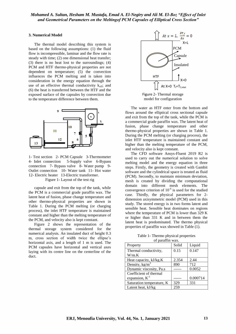
The test rig consists, as shown in Fig. 1, of a
cube tank (10) made of galvanized steel sheet with
a diameter of 30 cm and 30 cm height. The tank is
used to supply the test section with hot water (11)
at different temperatures. The tank is insulated with
glass wool insulation to decrease the heat loss from
hot water in the tank. The tank is equipped with a
1 kW electric heater (12) connected to the electrical
main supply with a voltage cutoff adapter that
provides a voltage variation from 0 to 220 V to
adjust the water temperature in the tank at a
predefined temperature. The reservoir is equipped
with a small 100-Watt pump (8) connected to the
tank bottom to supply the test section with hot
water required to heat the capsule at different
velocities using valve (7) which regulates the water
discharge rate to the test section (1).
The test section (1) is a rectangular cross
section channel of 8 cm by 10 cm cross section and
15 cm height. Hot water is brought to it by 1/2"
pipe diameter (4) connected to the bottom of the
channel through the pump (8). To drain the water
into the hot water tank, a hole of 1/2" diameter is
used and a tube (9) of the same diameter is
connected to one side near the top of the channel to
return the water back to the hot water tank. The
inlet water temperature is measured using the
thermometer (3). The Pyrex glass capsule (2) filled
with PCM is placed in a horizontal position using a
1 mm diameter wire carrier. It has an elliptical
cross section, with axes dimensions of 6.2 and 2.6
cm. It is filled with the molten paraffin, then left to
cool and closed with its lid.
To facilitate the vision and image of the
capsule, the test section was made from Plexiglass.
In order to measure the average temperature of the
water before entering the channel, a thermometer
(3) is fixed inside the channel (1). The rate of hot
water passing through the test section is measured
by the amount of water collected at a given time
during the experiment. The camera of a mobile
model Samsung Galaxy j2 is used to take the
photos of the capsule during melting process.
Mohamed A. Sultan, Hesham M. Mustafa, Emad A. El-Negiry and Ali M. El-Boz “Effect of Inlet
and Geometrical Parameters on the Meltingof PCM Capsules of Elliptical Cross Section”
ERJ, Menoufia University, Vol. 44, No. 1, January 2021 13
X=0
X=L
At X=0 Tf=Tf,inlet
Insulated
wall
Capsule
wall
PCM
Capsule
wall wall
HTF
Figure 2- Thermal storage
model for configuration
numerical analysis
3. Numerical Model
The thermal model describing this system is
based on the following assumptions: (1) the fluid
flow is incompressible, laminar and the flow rate is
steady with time; (2) one dimensional heat transfer;
(3) there is no heat lost to the surroundings; (4)
PCM and HTF thermo-physical properties are not
dependent on temperature; (5) the convection
influences the PCM melting and is taken into
consideration in the energy equation through the
use of an effective thermal conductivity keff; and
(6) the heat is transferred between the HTF and the
exposed surface of the capsules by convection due
to the temperature difference between them.
1- Test section 2- PCM Capsule 3-Thermometer
4- Inlet connection 5-Supply valve 6-Bypass
connection 7- Bypass valve 8- Water pump 9-
Outlet connection 10- Water tank 11- Hot water
12- Electric heater 13-Electric transformer.
Figure 1- Layout of the test rig
capsule and exit from the top of the tank, while
the PCM is a commercial grade paraffin wax. The
latent heat of fusion, phase change temperature and
other thermo-physical properties are shown in
Table 1. During the PCM melting (or charging
process), the inlet HTF temperature is maintained
constant and higher than the melting temperature of
the PCM, and velocity also is kept constant. Figure 2 shows the representation of the
thermal storage system considered for the
numerical analysis. An insulated duct of height 0.3
m, cross section of width twice the ellipse’s
horizontal axis, and a length of 1 m is used. The
PCM capsules have horizontal and vertical axes
laying with its centre line on the centerline of the
duct.
The water as HTF enter from the bottom and
flows around the elliptical cross sectional capsule
and exit from the top of the tank, while the PCM is
a commercial grade paraffin wax. The latent heat of
fusion, phase change temperature and other
thermo-physical properties are shown in Table 1.
During the PCM melting (or charging process), the
inlet HTF temperature is maintained constant and
higher than the melting temperature of the PCM,
and velocity also is kept constant.
The CFD software Ansys-Fluent 2019 R2 is
used to carry out the numerical solution to solve
melting model and the energy equation in three
steps. Firstly, the geometry is created with Gambit
software and the cylindrical space is treated as fluid
(PCM). Secondly, to maintain minimum deviation,
mesh is created by dividing the computational
domain into different mesh elements. The
convergence criterion of 10-6
is used for the studied
case. Thirdly, the physical parameters for 2-
dimension axisymmetric model (PCM) used in this
study. The stored energy is in two forms latent and
sensible heat. Sensible heat dominates on regions
where the temperature of PCM is lower than 329 K
or higher than 331 K and in between them the
latent heat is predominated. The thermo physical
properties of paraffin wax showed in Table (1).
Table 1- Thermo physical properties
of paraffin wax.
Liquid Solid Property
0.147 0.15 Thermal conductivity,
W/m.K
2.44 2.354 Heat capacity, kJ/kg.K
712 890 Density, kg/m3
0.0052 ------ Dynamic viscosity, Pa.s
0.000714
------
Coefficient of thermal
expansion, K-1
331 329 Saturation temperature, K 259 Latent heat, kJ/kg
Mohamed A. Sultan, Hesham M. Mustafa, Emad A. El-Negiry and Ali M. El-Boz “Effect of Inlet
and Geometrical Parameters on the Meltingof PCM Capsules of Elliptical Cross Section”
ERJ, Menoufia University, Vol. 44, No. 1, January 2021 14
4. Governing Equations
Voller and Prakash [21] and Voller and
Swaminathan [22] formulated the enthalpy-
porosity model to simulate the process of phase
change. The solid-liquid mushy zone in this model
was considered as a porous medium where its
porosity was equal to the liquid fraction of the
molten PCM. The liquid fraction, , was specified
as the volume ratio of the molten PCM to its total
volume. The porosity and liquid fraction is ranged
from 0 at the beginning of the melting process to 1
at the complete melting of PCM. Based on the
enthalpy equilibrium the liquid fraction is
calculated at each step. The porosity of the material
becomes zero when it has fully solidified in the cell
that makes the velocities equal to zero. This
attitude of the interface as per Darcy’s law
damping mechanism is contained in the momentum
equation as a source term due to the phase change
effect on natural convection.
The summation of the sensible enthalpy, h, and
latent heat, ∆H, is the total enthalpy of the material:
H = h+ ∆H (1)
In terms of the material latent heat L, the heat
of fusion can be written as:
∆H = λ*L (2)
where ∆H varies from L (liquid) to zero (solid),
therefore, one can define the liquid fraction, λ as:
λ
(3-a)
λ
(3-b)
λ
(3-c)
Energy equation
The energy equation for the melting model is
written as, [22]:
𝜕
𝜕 ( ) ( ) ( ) (4)
The solution for temperature is principally an
iterative between the energy equation and the liquid
fraction equation.
Continuity equation
(5)
Momentum equation
The mushy zone is treated as a porous medium
in the enthalpy-porosity technique, and in
momentum equation, the porosity in every cell is
taken equal to the cell liquid fraction. The porosity
in fully solidified regions is equal to zero, which
vanish the velocities in these regions. The damping
term of the momentum sink that is added to the
momentum equation due to the phase change effect
on convection is, [22]:
( λ
)
(λ ) (6)
where λ is the liquid fraction, is the mushy zone
constant, it is a small number (0.001) to avoid
division by zero.
The momentum equation for the melting
problem is written as [23]:
(
( )) (7)
The elliptical section is drawn in the GAMBIT
software program so that the axes ratio can be
changed to any desired value, including an axes
ratio of 1 which represents the circular cross-
section.
5. Results and Discussion
Firstly, the mesh independence study is
performed to determine the suitable grid size
followed by a comparison between the
experimental and numerical results to validate the
numerical solution.
5.1 Grid independence study
To solve the numerical model a free triangular
mesh is chosen. In order to examine the numerical
results dependent on the mesh size a simulation is
run on a circular cylindrical capsule of 4 cm
diameter and 6 cm length. The capsule initial
temperature is equal to 300 K, while at any time
higher than zero, the heat transfer fluid is at 343 K.
The capsule liquid fraction and mean temperature
are compared for different mesh sizes and it is
shown from Figs. 3 and 4 that mesh size of 0.00035
m can be used to solve the numerical model
accurately.
Similarly, the grid independence study is
carried out for other configurations of the elliptical
capsules. Time step used in the analysis is 0.5 s
throughout all models.

Mohamed A. Sultan, Hesham M. Mustafa, Emad A. El-Negiry and Ali M. El-Boz “Effect of Inlet
and Geometrical Parameters on the Meltingof PCM Capsules of Elliptical Cross Section”
ERJ, Menoufia University, Vol. 44, No. 1, January 2021 15
Figure 3- Effect of mesh size on PCM liquid
fraction at constant HTF inlet temperature of 343 K
and velocity of 0.003 m/s
Figure 4- Effect of mesh size on PCM mean
temperature at constant HTF inlet temperature of
343 K and velocity of 0.003 m/s
5.2 Validation of numerical results
A comparison between the experimental results
of the elliptical cross section capsule of Ar = 2.6
with the numerical results of a capsule of the same
shape and dimensions, obtained from the numerical
model was made.
Fig. 5 illustrates as a contour the variation of
the liquid fraction of PCM melting with the
pictures that were captured during the experiments
for HTF initial velocity and temperature of 0.003
m/s and 340 K, respectively. It is shown from the
figure that there is a fair agreement between the
experimental and numerical results and the shape
of molten and solid paraffin.
Figure 5- Comparison between liquid fraction
contours and camera photos of paraffin wax
elliptical cross sectional capsule
The experimental results of liquid fraction are
calculated from the camera photos using two
programs, the first of which is an online photo
editor called “Photopea” at www.photopea.com
which is used to eliminate the elliptical capsule
from the photo. The second program is online
“Image Color Extract Tool” at
www.coolphptools.com/color_extract#demo wich
enables the determination of the percentage of the
solid “white color” and the liquid “gray color”.
Fig. 6 shows the relation between liquid
fraction and time for both experimental and
theoretical results for an oblate capsule of Ar = 2.61
at HTF inlet temperature of 340 K and a velocity of
0.003 m/s. It is seen from the figure that the two
results are in fair agreement.
Figure 6- Comparison between experimental and
theoretical PCM liquid fraction results of capsule
with axes ratio 2.61 at HTF inlet temperature of
340 K and velocity of 0.003 m/s
The fair agreement between the numerical and
experimental results ensures the numerical model
validity of and the accuracy of different paraffin
wax thermal properties.
Mohamed A. Sultan, Hesham M. Mustafa, Emad A. El-Negiry and Ali M. El-Boz “Effect of Inlet
and Geometrical Parameters on the Meltingof PCM Capsules of Elliptical Cross Section”
ERJ, Menoufia University, Vol. 44, No. 1, January 2021 16
5.3 Effect of discussed parameters
In the following section, the effect of the axes
ratio of the elliptical cross section-capsule, the inlet
temperature and velocity of the heat transfer fluid
(HTF) will be discussed.
Effect of axes ratio
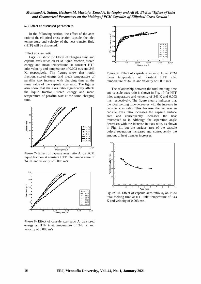
Figs. 7-9 show the Effect of charging time and
capsule axes ratios on PCM liquid fraction, stored
energy and mean temperature, at constant HTF
inlet velocity and temperature of 0.003 m/s and 343
K, respectively. The figures show that liquid
fraction, stored energy and mean temperature of
paraffin wax increase with charging time at the
same value of the capsule axes ratio. The figures
also show that the axes ratio significantly affects
the liquid fraction, stored energy and mean
temperature of paraffin wax at the same charging
time.
Figure 7- Effect of capsule axes ratio Ar on PCM
liquid fraction at constant HTF inlet temperature of
343 K and velocity of 0.003 m/s
Figure 8- Effect of capsule axes ratio Ar on stored
energy at HTF inlet temperature of 343 K and
velocity of 0.003 m/s
Figure 9. Effect of capsule axes ratio Ar on PCM
mean temperature at constant HTF inlet
temperature of 343 K and velocity of 0.003 m/s
The relationship between the total melting time
and capsule axes ratio is shown in Fig. 10 for HTF
inlet temperature and velocity of 343 K and 0.003
m/s, respectively. The figure clearly indicates that
the total melting time decreases with the increase in
capsule axes ratio. This because the increase in
capsule axes ratio increases the capsule surface
area and consequently increases the heat
transferred to it. Although the separation angle
decreases with the increase in axes ratio, as shown
in Fig. 11, but the surface area of the capsule
before separation increases and consequently the
amount of heat transfer increases.
Figure 10- Effect of capsule axes ratio Ar on PCM
total melting time at HTF inlet temperature of 343
K and velocity of 0.003 m/s.
Mohamed A. Sultan, Hesham M. Mustafa, Emad A. El-Negiry and Ali M. El-Boz “Effect of Inlet
and Geometrical Parameters on the Meltingof PCM Capsules of Elliptical Cross Section”
ERJ, Menoufia University, Vol. 44, No. 1, January 2021 17
Figure 11- Velocity contours for different aspect
ratios
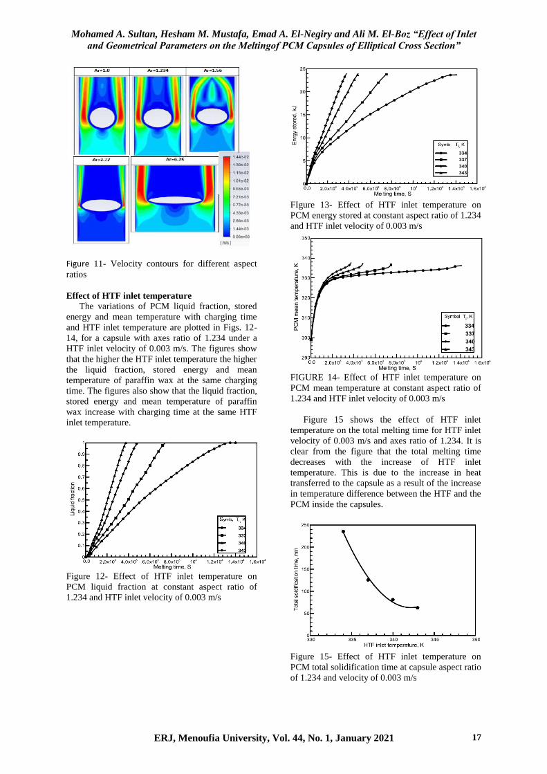
Effect of HTF inlet temperature
The variations of PCM liquid fraction, stored
energy and mean temperature with charging time
and HTF inlet temperature are plotted in Figs. 12-
14, for a capsule with axes ratio of 1.234 under a
HTF inlet velocity of 0.003 m/s. The figures show
that the higher the HTF inlet temperature the higher
the liquid fraction, stored energy and mean
temperature of paraffin wax at the same charging
time. The figures also show that the liquid fraction,
stored energy and mean temperature of paraffin
wax increase with charging time at the same HTF
inlet temperature.
Figure 12- Effect of HTF inlet temperature on
PCM liquid fraction at constant aspect ratio of
1.234 and HTF inlet velocity of 0.003 m/s
FIgure 13- Effect of HTF inlet temperature on
PCM energy stored at constant aspect ratio of 1.234
and HTF inlet velocity of 0.003 m/s
FIGURE 14- Effect of HTF inlet temperature on
PCM mean temperature at constant aspect ratio of
1.234 and HTF inlet velocity of 0.003 m/s
Figure 15 shows the effect of HTF inlet
temperature on the total melting time for HTF inlet
velocity of 0.003 m/s and axes ratio of 1.234. It is
clear from the figure that the total melting time
decreases with the increase of HTF inlet
temperature. This is due to the increase in heat
transferred to the capsule as a result of the increase
in temperature difference between the HTF and the
PCM inside the capsules.
Figure 15- Effect of HTF inlet temperature on
PCM total solidification time at capsule aspect ratio
of 1.234 and velocity of 0.003 m/s

Mohamed A. Sultan, Hesham M. Mustafa, Emad A. El-Negiry and Ali M. El-Boz “Effect of Inlet
and Geometrical Parameters on the Meltingof PCM Capsules of Elliptical Cross Section”
ERJ, Menoufia University, Vol. 44, No. 1, January 2021 18
Effect of HTF inlet velocity
PCM mean temperature and liquid fraction as a
function of melting time are plotted in Figs. 16-17.
The axes ratio and HTF inlet temperature are kept
constant at 1.234 and 343 K, respectively, while the
HTF inlet velocity is ranged from 0.003 to 0.012
m/s. The figures indicate that the liquid fraction
and mean temperature of paraffin wax increase
with charging time at the same HTF inlet velocity.
It is also shown from the figures that the liquid
fraction slightly increases whilethe mean
temperature of paraffin wax is kept nearly constant
with HTF inlet velocity at the same charging time.
Figure 16- Effect of HTF inlet temperature on
PCM liquid fraction at constant axes ratio of 1.234
and HTF inlet temperature of 343 K.
Figure 17- Effect of HTF inlet temperature on
PCM mean temperature at constant axes ratio of
1.234 and HTF inlet temperature of 343 K
Figure 18 illustrates the relationship between
total melting time and HTF inlet velocity for axes
ratio of 1.234 and HTF inlet temperature of 343 K.
It is seen from the figure that the total melting time
slightly increases with the decrease of HTF inlet
velocity. This is because increasing the HTF inlet
velocity decreases the heat transfer resistance by
only a small value while the other thermal
resistances of PCM is still very small compared to
it.
Figure 18. Effect of HTF inlet velocity on PCM
total melting time at capsule aspect ratio of 1.234
and HTF inlet temperature of 343 K.
6. Conclusions
From the above-discussed results of the process
of paraffin wax melting inside elliptical cross-
sectional capsules of different axes ratio under HTF
flowing with different inlet velocities and
temperatures, the following conclusions are made:
1- The increase of HTF inlet velocity has a
weak effect on the paraffin wax melting time in the
2- The geometry of the capsule cross-section
represented by its axes ratio has a remarkable effect
on the process of paraffin wax melting. Increasing
the axes ratio of the capsule, i.e. elongated the
capsule in the perpendicular direction of flow,
increases the PCM liquid fraction and decreases the
total time of melting of the capsulated paraffin wax
3-The inlet temperature of the heat transfer
fluid (HTF) has a great effect on the process of
paraffin wax melting. The increase of HTF inlet
temperatures increases the PCM liquid fraction and
decreases at the same time the total time of melting
of the capsulated paraffin wax.

Mohamed A. Sultan, Hesham M. Mustafa, Emad A. El-Negiry and Ali M. El-Boz “Effect of Inlet
and Geometrical Parameters on the Meltingof PCM Capsules of Elliptical Cross Section”
ERJ, Menoufia University, Vol. 44, No. 1, January 2021 19
7. Nomenclature
A: Surface area of test tube, m2
Cp: Specific heat at constant pressure, J/kg.K
D: Diameter, m
E: Total energy stored, kJ/kg
g: Acceleration of gravity, m/sec2
H: Total enthalpy, J/kg
h: Sensible enthalpy, J/kg
k: Thermal conductivity, W/m.K
L: Latent heat of fusion, J/kg
Q: Heat transfer rate, W
q: Heat flux, W/m2
: Source term
t: Time, s
: Velocity vector
Greek Symbols
: Volumetric expansion coefficient (K-1
)
∆H: Latent heat, J/kg
λ: Liquid fraction (%)
μ: Dynamic viscosity, kg/m.s
ρ: Density, kg/m3
Abbreviations
CFD: Computational Fluid Dynamics
EPCM: Encapsulated Phase Change Material
HTF: Heat Transfer Fluid
LHS: Latent Heat Storage
PCM: Phase Change Material
SHS: Sensible Heat Storage
TES: Thermal Energy Storage
8. References
[1] V. Kapsalis, and D. Karamanis, “Solar
thermal energy storage and heat pumps with
phase change materials,” Appl. Therm. Eng.
99(2016) 1212–1224.
[2] B. Zalba, J.M. Marin, L.F. Cabeza, and H.
Mehling, “Review on thermal energy storage
with phase change: materials, heat transfer
analysis and applications,” Appl. Therm. Eng.
23(2003) 251–283.
[3] A. Sharma, V.V. Tyagi, C.R. Chen, and D.
Buddhi, “Review on thermal energy storage
with phase change materials and
applications,” Renewable and Sustainable
Energy Reviews 13(2009) 318–345.
[4] J. Yang, L. Yang, C. Xu, and X. Du,
“Experimental study on enhancement of
thermal energy storage with phase-change
material,” Applied Energy 169(C)(2016)
164–176.
[5] J. Wei, Y. Kawaguchi, S. Hirano, and H.
Takeuchi, “Study on a PCM heat storage
system for rapid heat supply,” Appl. Therm.
Eng. 25(2005) 2903–2920.
[6] K. Siva, M.X. Lawrence, G.R.Kumaresh,
P.Rajagopalan, and H.Santhanam,
“Experimental and numerical investigation of
phase change materials with finned
encapsulation for energy efficient buildings,”
Journal of Building Performance
Simulation3(4)(2010) 245–254.
[7] S. Kalaiselvam, M. Veerappan, A. Arul
Aaron, and S. Iniyan, “Experimental and
analytical investigation of solidification and
melting characteristics of PCMs inside
cylindrical encapsulation,” Int. J. Therm. Sci.
47(2008) 858–874.
[8] A. Felix Regin, S.C. Solanki, and J.S. Saini,
“Latent heat thermal energy storage using
cylindrical capsule: numerical and
experimental investigations,” Renew. Energy
31(2006) 2025–2041.
[9] K. ElOmari, T. Kousksou, and Y. LeGuer,
“Impact of shape of container on natural
convection and melting inside enclosures
used for passive cooling of electronic
devices,” Appl. Therm. Eng. 31(2011)3022–
3035.
[10] T. Saitoh, and K. Hirose, “High Rayleigh
number solutions to problems of latent heat
thermal energy storage in a horizontal
cylinder capsule,”ASME J. Heat Transf.
104(1982) 545–553.
[11] H. Rieger, U. Projahn, M. Bareiss, and H.
Beer, “Heat transfer during melting inside a
horizontal tube,” ASME J. Heat Transf.
105(1983)226–234.
[12] C.J. Ho, and R. Viskanta, “Heat transfer
during inwardmelting in a horizontal tube,”
Int. J. Heat Mass Transf. 27(1984)705–716.
[13] H.S. Yoo, and S.T. Ro, “Numerical analysis
of the phase change processes by coordinate
transformations,” Trans. KSME 10(1986)
585–592.
[14] A. Prasad, and S. Sengupta, “Nusselt number
and melt time correlations for melting inside
a horizontal cylinder subjected to an
isothermal wall temperature condition,”
ASME J. Heat Tansf.110(1988) 340–345.
[15] F. Agyenim, N. Hewitt, P. Eames, and M.
Smyth, “A review of materials, heat transfer
and phase change problem formulation for
latent heat thermal energy storage systems
(LHTESS),” Renewable and Sustainable
Energy Reviews 14(2010) 615–628.
[16] M. Palanisamy, and H. Niyas, “Comparison
of thermal characteristics of sensible and latent
heat storage materials encapsulatedin different
capsule configurations.”In: Concentrated
Solar Thermal Energy Technologies, pp. 11–
20, Springer, Singapore, 2018.
[17] B.J. Jones, D. Sun, S. Krishnan, and S.V.
Garimella, “Experimental and numerical
study of melting in a cylinder,” Int. J. Heat
Mass Transf.49(2006) 2724–2738.

Mohamed A. Sultan, Hesham M. Mustafa, Emad A. El-Negiry and Ali M. El-Boz “Effect of Inlet
and Geometrical Parameters on the Meltingof PCM Capsules of Elliptical Cross Section”
20 ERJ, Menoufia University, Vol. 44, No. 1, January 2021
[18] E. Assis, L. Katsman, G. Ziskind, and R.
Letan, “Numerical and experimental study of
melting in a spherical shell,” Int. J. Heat
Mass Transf. 50(2007) 1790–1804.
[19] F.L. Tan, S.F. Hosseinizadeh,J.M.
Khodadadi, and L. Fan, “Experimental and
computational study of constrained melting
of phase change materials (PCM) inside a
spherical capsule,”Int. J. Heat Mass Transf.
52(2009)3464–3472.
[20] N. Sharifi, T.L. Bergman, M.J. Allen, and A.
Faghri, “Melting and solidification
enhancement using a combined heat pipe,
foil approach,” Int. J. Heat Mass Transf.
78(2014) 930–941.
[21] M.A. Sultan, E.A. El-Negiry, H.M. Mustafa,
and A.M. El-Boz, “Experimental and
computational study of melting of paraffin
wax inside a cylindrical capsules of elliptical
cross section,” Engineering Research
Journal 43(2)(2020) 99–108, Faculty of
Engineering, Menoufia University, Egypt.
[22] V.R. Voller, and C. Prakash, “A fixed grid
numerical modeling methodology for
convection-diffusion mushy region phase-
change problems,” Int. J. Heat Mass Transf.
30(8)(1987)1709–1719.
[23] V.R. Voller, and C.R. Swaminathan,
“General source-based method for
solidification phase change,” Numer. Heat
Transf. Part B Fundam. 19(2)(1991) 175–
189.