Joseph Ong Aug 2005 Company Confidential 1
Earthing / Grounding Issues
Reasons for Earthing and Bonding• Detect fault current and fast removal of
power source at fault• Prevent potential differences which may
cause electrocution or sparks• Minimise the effect of lightning strikes• Prevent build-up of ESD• Minimise the effect of electrical interferences• Meet Explosion-Proof apparatus safety
requirementsReference: MTL website
Joseph Ong Aug 2005 Company Confidential 2
Earthing / Grounding Issues
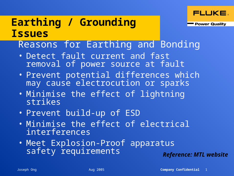
Ground / earth resistance and resistivity should be measured when:
• Installing new ground systems and electrical equipment
• Periodically testing of ground and lightning protection rods
• Prior to design of ground protection systems
Joseph Ong Aug 2005 Company Confidential 3
Earth Testing Methods
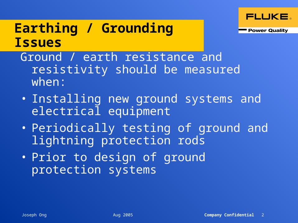
• Fall of Potential – 3 and 4 Pole Testing
• Resistivity
• Selective Testing
• Stakeless Testing
Joseph Ong Aug 2005 Company Confidential 4
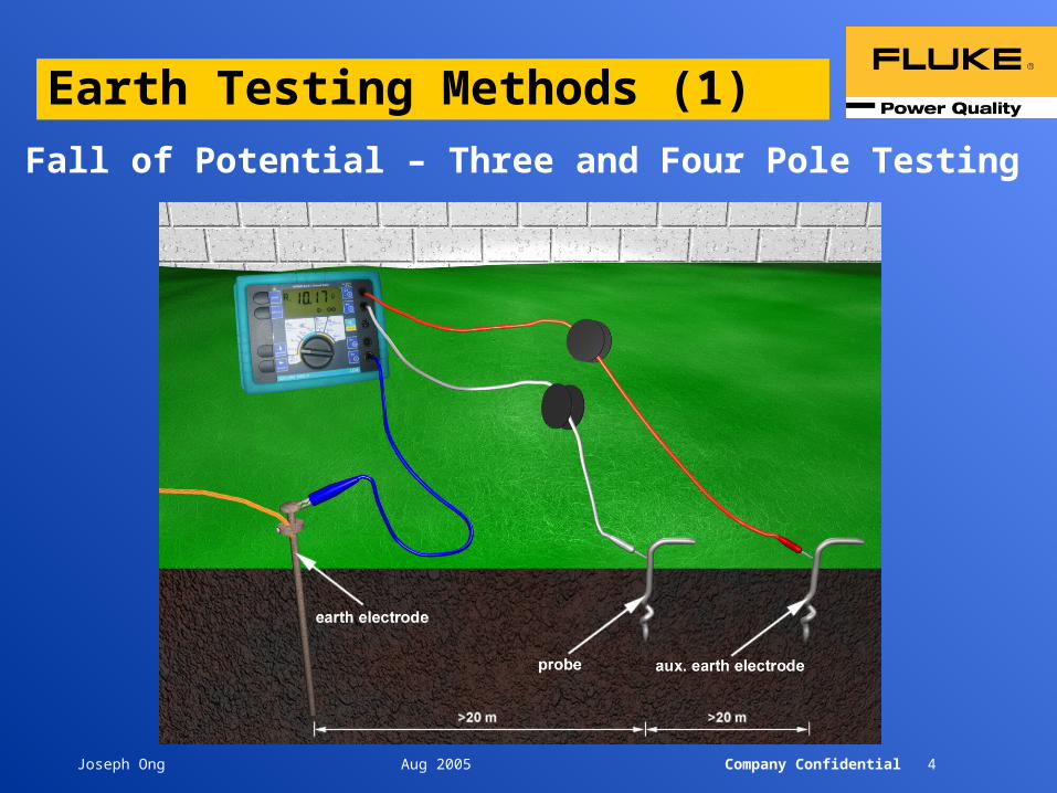
Earth Testing Methods (1)
Fall of Potential – Three and Four Pole Testing
Joseph Ong Aug 2005 Company Confidential 5
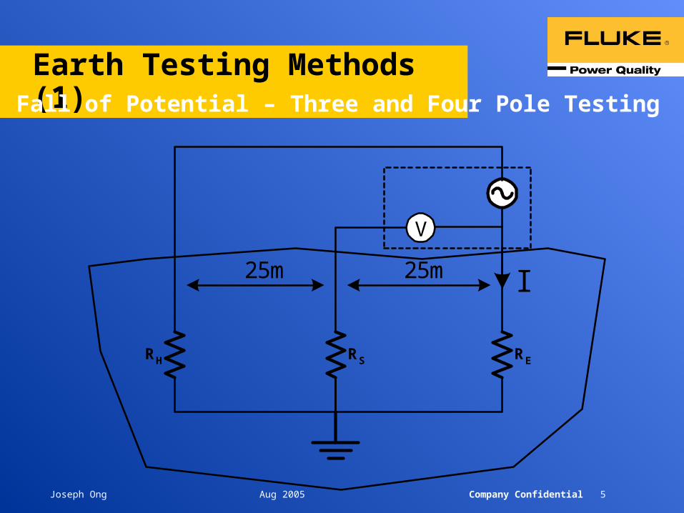
Earth Testing Methods (1)Fall of Potential – Three and Four Pole Testing
RH RS RE
V
25m 25m I
Joseph Ong Aug 2005 Company Confidential 6
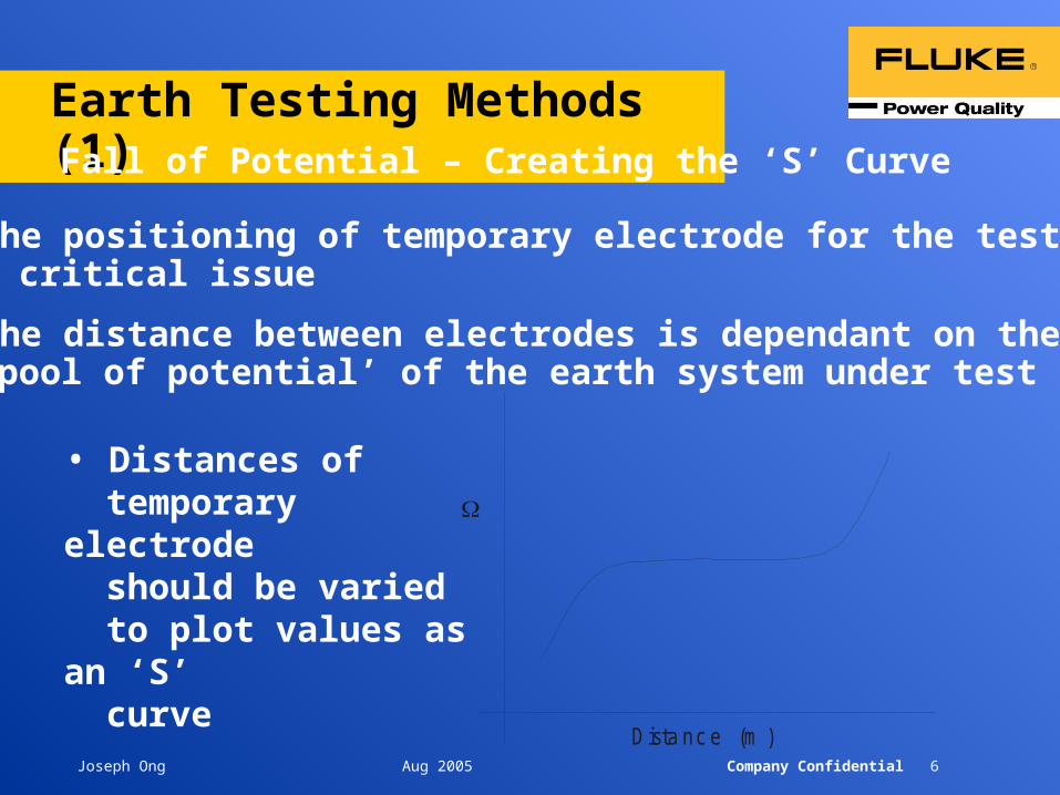
Earth Testing Methods (1)Fall of Potential – Creating the ‘S’ Curve
• The positioning of temporary electrode for the test is a critical issue
• The distance between electrodes is dependant on the ‘pool of potential’ of the earth system under test
Dista nc e (m )
• Distances of temporary electrode should be varied to plot values as an ‘S’ curve

Joseph Ong Aug 2005 Company Confidential 7
Earth Testing Methods (2)Resistivity Measurement
From the indicated resistance value RE, the soil resistivity calculates according to the equation :
E = 2 . a . R E
E ...... mean value of soil resistivity (.m)RE ...... measured resistance (a ...... probe distance (m)
Joseph Ong Aug 2005 Company Confidential 8
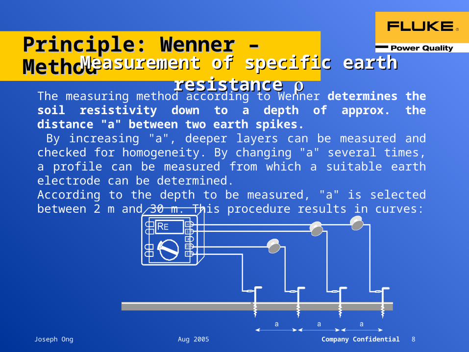
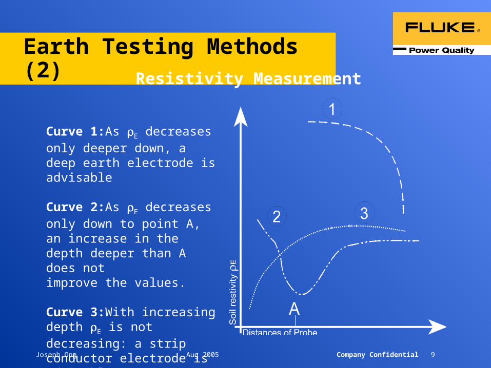
Principle: Wenner – MethodPrinciple: Wenner – MethodMeasurement of specific earth resistance Measurement of specific earth resistance
The measuring method according to Wenner determines the soil resistivity down to a depth of approx. the distance "a" between two earth spikes. By increasing "a", deeper layers can be measured and checked for homogeneity. By changing "a" several times, a profile can be measured from which a suitable earth electrode can be determined. According to the depth to be measured, "a" is selected between 2 m and 30 m. This procedure results in curves:
Joseph Ong Aug 2005 Company Confidential 9
Earth Testing Methods (2)
Curve 1:As E decreases only deeper down, a deep earth electrode is advisable
Curve 2:As E decreases only down to point A, an increase in the depth deeper than A does not improve the values.
Curve 3:With increasing depth E is not decreasing: a strip conductor electrode is advisable.
Resistivity Measurement
Joseph Ong Aug 2005 Company Confidential 10
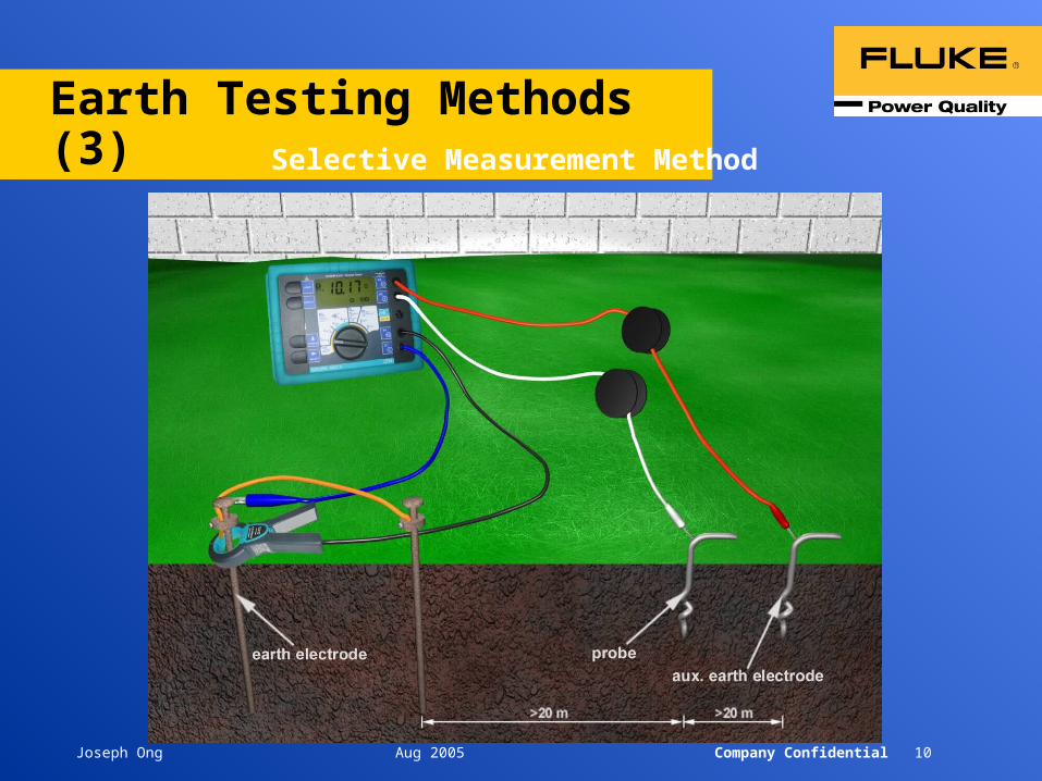
Earth Testing Methods (3)Selective Measurement Method
Joseph Ong Aug 2005 Company Confidential 11
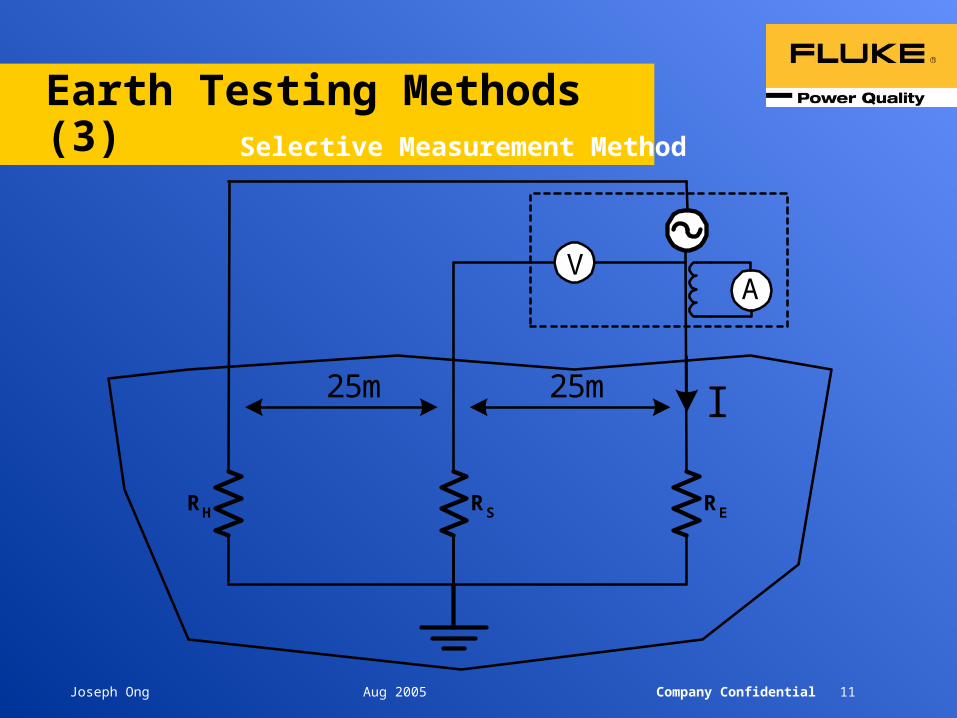
Earth Testing Methods (3)Selective Measurement Method
RH RS RE
V
25m 25m
A
I
Joseph Ong Aug 2005 Company Confidential 12
Earth Testing Methods (3)
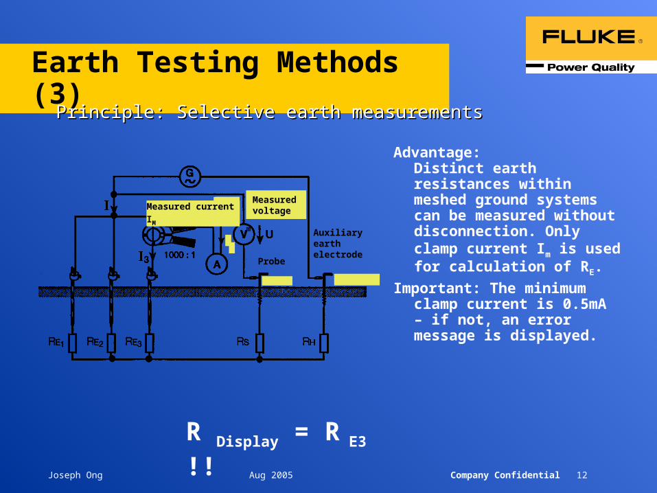
Principle: Selective earth measurementsPrinciple: Selective earth measurements
Advantage: Distinct earth resistances within meshed ground systems can be measured without disconnection. Only clamp current Im is used for calculation of RE.
Important: The minimum clamp current is 0.5mA – if not, an error message is displayed.
R Display = R E3 !!
Im
MeasuredvoltageMeasured current IM
Probe
Auxiliaryearthelectrode
Joseph Ong Aug 2005 Company Confidential 13
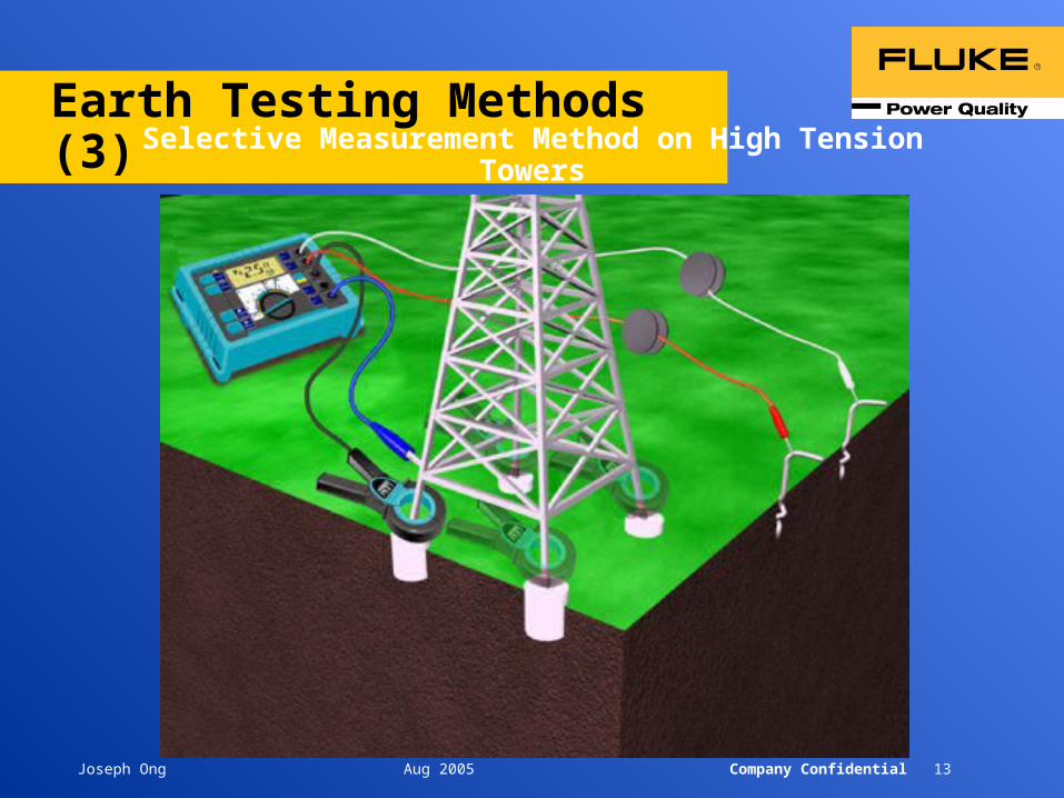
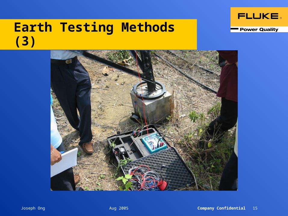
Earth Testing Methods (3)Selective Measurement Method on High Tension Towers

Joseph Ong Aug 2005 Company Confidential 14
Earth Testing Methods (3)Measurements on high tension towers
• Applicable for nearly all metal constructions!
• Example: Tower with four stands.
• Important: Do not move the current injection point (E) during test!
• All stands are tested in sequence with the split core transformer.
ring earthelectrode
split core transformer
Joseph Ong Aug 2005 Company Confidential 15
Earth Testing Methods (3)
Joseph Ong Aug 2005 Company Confidential 16
Earth Testing Methods (4)
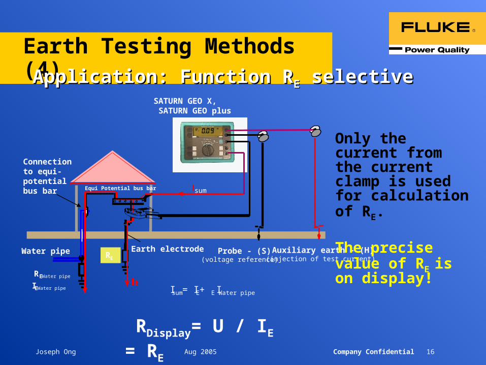
RDisplay= U / IE = RE
Connectionto equi-potentialbus bar Equi Potential bus bar
Water pipe Earth electrode
RE Water pipe
IE Water pipe Isum = IE + IE Water pipe
Probe - (S)(voltage reference)
Auxiliary earth - (H)(injection of test current)
Application: Function RApplication: Function REE selective selective
Only the current from the current clamp is used for calculation of RE.
The precise value of RE is on display!
RE
sum
SATURN GEO X, SATURN GEO plus

Joseph Ong Aug 2005 Company Confidential 17
Earth Testing Methods (4)Stakeless Measurement Method
Joseph Ong Aug 2005 Company Confidential 18
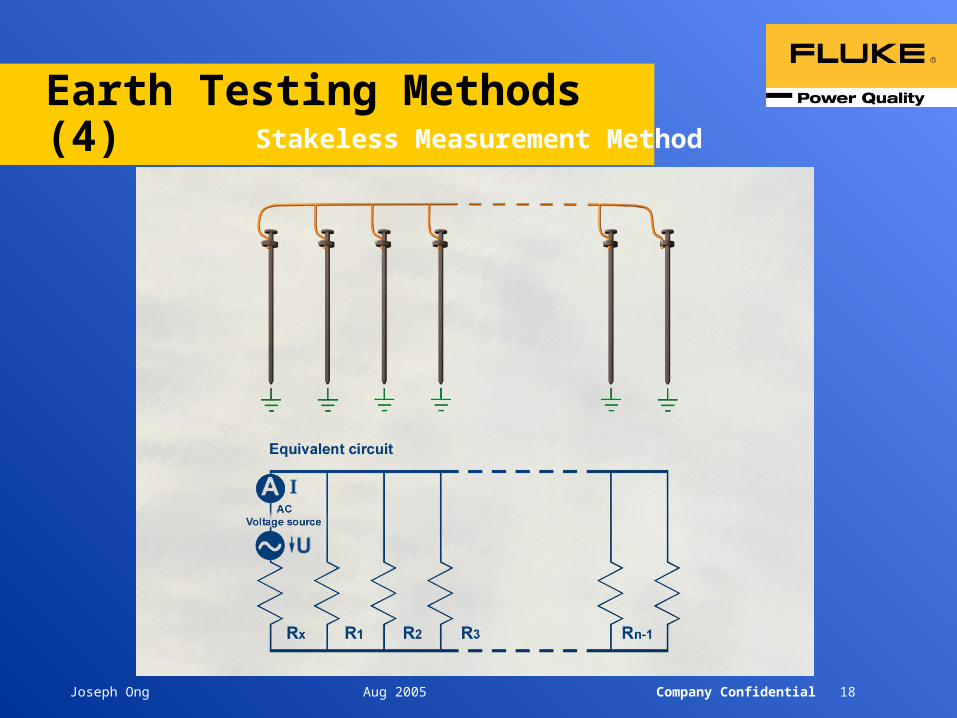
Earth Testing Methods (4)Stakeless Measurement Method
Joseph Ong Aug 2005 Company Confidential 19
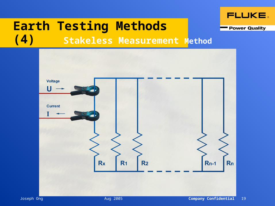
Earth Testing Methods (4)Stakeless Measurement Method
Joseph Ong Aug 2005 Company Confidential 20
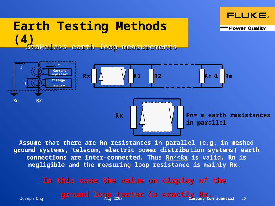
Earth Testing Methods (4)
Assume that there are Rn resistances in parallel (e.g. in meshed ground systems, telecom, electric power distribution systems) earth connections are inter-connected.
Thus Rn<<Rx is valid. Rn is negligible and the measuring loop resistance is mainly Rx.
In this case the value on display of the In this case the value on display of the
ground loop tester is exactly Rx.ground loop tester is exactly Rx.
Current amplifier
Voltage
source
II
RxRn
U
Stakeless earth loop measurementsStakeless earth loop measurements
Rx R1 R2 Rm-1 Rm
Rx
Rx R1 R2 Rm-1 Rm
Rx Rn= m earth resistances in parallel

Joseph Ong Aug 2005 Company Confidential 21
Earth Testing Methods (4)Principle: Stakeless earth measurementsPrinciple: Stakeless earth measurements
Erder
black
red
• For all applications with at least two earth electrodes...e.g. high tension towers, meshed grounding systems,
• telecom-cables ......
Simply put both clamps around conductor, cable, pipe etc.
Clamps with a large variety of openings are available.
> 10cm
Earth electrode
Adapter – for GEO X only
Joseph Ong Aug 2005 Company Confidential 22
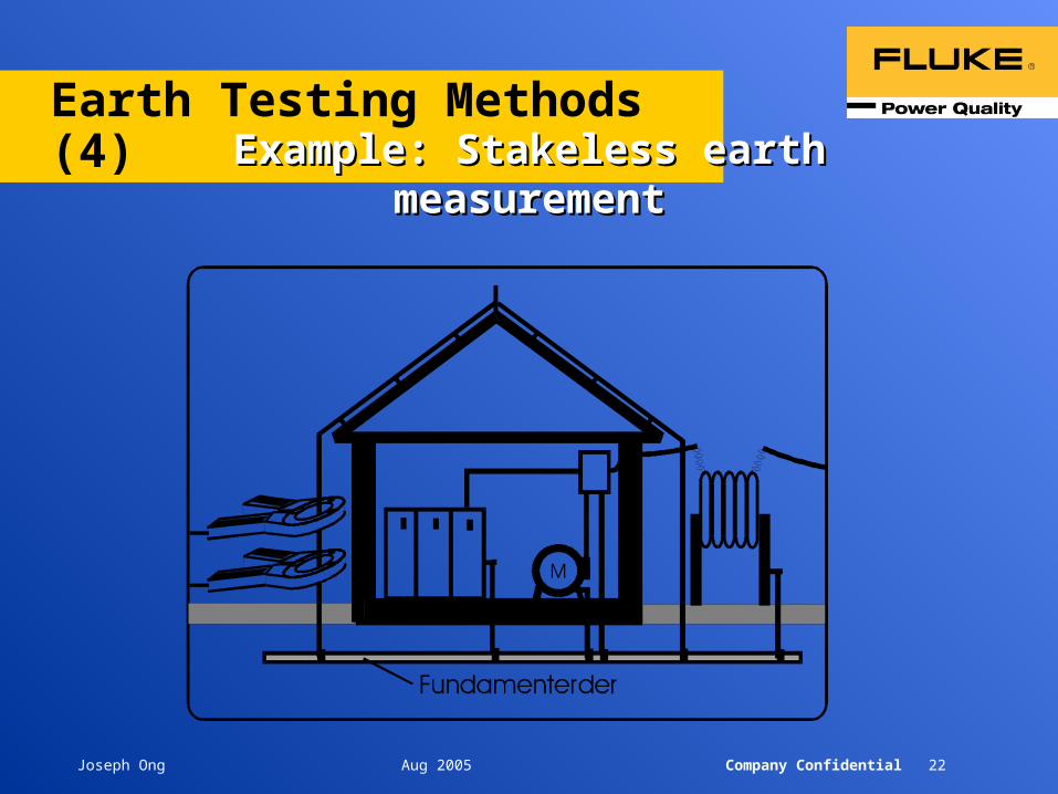
Earth Testing Methods (4)
Example: Stakeless earth measurementExample: Stakeless earth measurement


![Metric References Grounding & Earthing Solutions - … · Grounding & Earthing Solutions GroundingSuperstore TM The METRIC VERSION (TXLYDOHQW 0HWULF 6L]H JLYHQ LQ > @ 0HWULF VL]HV](https://static.cupdf.com/doc/110x72/5b79fa717f8b9a7f378ecbd4/metric-references-grounding-earthing-solutions-grounding-earthing-solutions.jpg)


![Metric References Grounding & Earthing Solutions · 2018-05-14 · Metric References Grounding & Earthing Solutions GroundingSuperstore TM The METRIC VERSION (TXLYDOHQW 0HWULF 6L]H](https://static.cupdf.com/doc/110x72/5e9b4bfe4c5e500c47698ce7/metric-references-grounding-earthing-solutions-2018-05-14-metric-references.jpg)